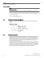
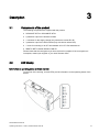
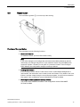
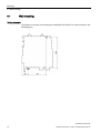
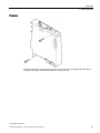
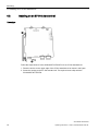
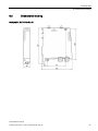
1
SCALANCE W770/W730
1
___________________
Information on the Internet
2
___________________
Introduction
SIMATIC NET
Industrial Wireless LAN
SCALANCE W770/W730
Operating Instructions
3
___________________
Description
4
___________________
Mounting
5
___________________
Connection
6
___________________
Technical data
7
___________________
Approvals
11/2014
C79000-G8976-C325-04
Legal information
Warning notice system
This manual contains notices you have to observe in order to ensure your personal safety, as well as to prevent
damage to property. The notices referring to your personal safety are highlighted in the manual by a safety alert
symbol, notices referring only to property damage have no safety alert symbol. These notices shown below are
graded according to the degree of danger.
DANGER
indicates that death or severe personal injury will result if proper precautions are not taken.
WARNING
indicates that death or severe personal injury may result if proper precautions are not taken.
CAUTION
indicates that minor personal injury can result if proper precautions are not taken.
NOTICE
indicates that property damage can result if proper precautions are not taken.
If more than one degree of danger is present, the warning notice representing the highest degree of danger will
be used. A notice warning of injury to persons with a safety alert symbol may also include a warning relating to
property damage.
Qualified Personnel
The product/system described in this documentation may be operated only by personnel qualified for the specific
task in accordance with the relevant documentation, in particular its warning notices and safety instructions.
Qualified personnel are those who, based on their training and experience, are capable of identifying risks and
avoiding potential hazards when working with these products/systems.
Proper use of Siemens products
Note the following:
WARNING
Siemens products may only be used for the applications described in the catalog and in the relevant technical
documentation. If products and components from other manufacturers are used, these must be recommended
or approved by Siemens. Proper transport, storage, installation, assembly, commissioning, operation and
maintenance are required to ensure that the products operate safely and without any problems. The permissible
ambient conditions must be complied with. The information in the relevant documentation must be observed.
Trademarks
All names identified by ® are registered trademarks of Siemens AG. The remaining trademarks in this publication
may be trademarks whose use by third parties for their own purposes could violate the rights of the owner.
Disclaimer of Liability
We have reviewed the contents of this publication to ensure consistency with the hardware and software
described. Since variance cannot be precluded entirely, we cannot guarantee full consistency. However, the
information in this publication is reviewed regularly and any necessary corrections are included in subsequent
editions.
Siemens AG
Division Process Industries and Drives
Postfach 48 48
90026 NÜRNBERG
GERMANY
C79000-G8976-C325-04
Ⓟ 11/2014 Subject to change
Copyright © Siemens AG 2013 - 2014.
All rights reserved
Contents
1
Information on the Internet ...................................................................................................................... 5
2
Introduction ............................................................................................................................................. 7
3
4
5
6
7
2.1
Information on the Operating Instructions ................................................................................ 7
2.2
Structure of the type designation .............................................................................................. 8
2.3
Security information .................................................................................................................. 8
Description .............................................................................................................................................. 9
3.1
Components of the product ...................................................................................................... 9
3.2
LED display ............................................................................................................................... 9
3.3
Reset button ............................................................................................................................11
Mounting ............................................................................................................................................... 13
4.1
Wall mounting .........................................................................................................................14
4.2
Installing on an S7-300 standard rail ......................................................................................16
4.3
Installing on an S7-1500 standard rail ....................................................................................17
4.4
Installing on a DIN rail / removing ...........................................................................................18
Connection ........................................................................................................................................... 21
5.1
Lightning protection, power supply and grounding .................................................................21
5.2
Power supply ..........................................................................................................................25
5.3
Ethernet ..................................................................................................................................28
5.4
Suitable cables for power supply and Ethernet ......................................................................29
5.5
Antenna connectors ................................................................................................................30
5.6
Suitable antenna cables and antennas...................................................................................31
5.7
Replacing the PLUG (C-PLUG or KEY-PLUG) ......................................................................32
Technical data ...................................................................................................................................... 35
6.1
Mechanical and electrical data ...............................................................................................35
6.2
Dimensional drawing...............................................................................................................37
Approvals.............................................................................................................................................. 41
Index..................................................................................................................................................... 43
SCALANCE W770/W730
Operating Instructions, 11/2014, C79000-G8976-C325-04
3
Contents
SCALANCE W770/W730
4
Operating Instructions, 11/2014, C79000-G8976-C325-04
Information on the Internet
1
Bitte beachten Sie die Warnhinweise und zusätzlichen Informationen in der
Kompaktbetriebsanleitung in Ihrer Sprache im Internet:
http://support.automation.siemens.com/ww/view/at/10806097
http://support.automation.siemens.com/ww/view/ch/10806097
http://support.automation.siemens.com/ww/view/de/10806097
http://support.automation.siemens.com/ww/view/li/10806097
http://support.automation.siemens.com/ww/view/lu/10806097
Please observe the warnings and additional information in the compact operating
instructions in your language in the Internet:
http://support.automation.siemens.com/ww/view/au/10806097
http://support.automation.siemens.com/ww/view/ca/10806097
http://support.automation.siemens.com/ww/view/gb/10806097
http://support.automation.siemens.com/ww/view/ie/10806097
http://support.automation.siemens.com/ww/view/us/10806097
http://support.automation.siemens.com/ww/view/za/10806097
Veuillez tenir compte des avertissements et informations supplémentaires de la notice de
service dans votre langue sur Internet:
http://support.automation.siemens.com/ww/view/be/10806097
http://support.automation.siemens.com/ww/view/ch/10806097
http://support.automation.siemens.com/ww/view/fr/10806097
http://support.automation.siemens.com/ww/view/lu/10806097
Si prega di tenere conto delle avvertenze e ulteriori informazioni nell’istruzione operativa
compatta nella relativa lingua in Internet:
http://support.automation.siemens.com/ww/view/it/10806097
Se ruega tener en cuenta las advertencias y las informaciones complementarias contenidas
en las instrucciones de servicio (resumen) en español en Internet:
http://support.automation.siemens.com/ww/view/cl/10806097
http://support.automation.siemens.com/ww/view/es/10806097
Dbejte prosím na výstražné pokyny a doplňkové informace v kompaktním návodu k obsluze
ve vašem jazyce na internetu:
http://support.automation.siemens.com/ww/view/cz/10806097
Vær venligst opmærksom på de advarselsanvisninger og ekstra informationer der findes på
dit sprog i kompaktdriftsvejledningen på internettet:
http://support.automation.siemens.com/ww/view/dk/10806097
Noudata lyhyen käyttöoppaan sisältämiä varoituksia ja huomio sen muutkin tiedot. Oman
kielisesi käyttöoppaan löydät internetistä osoitteesta:
http://support.automation.siemens.com/ww/view/fi/10806097
Λάβετε υπόψη τις υποδείξεις προειδοποίησης και τις πρόσθετες πληροφορίες των
συνοπτικών οδηγιών χρήσης που παρέχονται στη γλώσσα σας στο Διαδίκτυο:
http://support.automation.siemens.com/ww/view/gr/10806097
SCALANCE W770/W730
Operating Instructions, 11/2014, C79000-G8976-C325-04
5
Information on the Internet
请注意互联网上精编版操作说明相应语言版本中的警告提示和附加信息:
http://support.automation.siemens.com/ww/view/cn/10806097
http://support.automation.siemens.com/ww/view/hk/10806097
http://support.automation.siemens.com/ww/view/sg/10806097
Kérjük, vegye figyelembe az interneten található, az Ön anyanyelvén íródott kompakt
használati útmutatóban található figyelmeztetéseket és további információkat:
http://support.automation.siemens.com/ww/view/hu/10806097
Skoðið vel viðvaranir og aðrar upplýsingar í notkunarleiðbeiningunum á ykkar tungumáli á
internetinu:
http://support.automation.siemens.com/ww/view/is/10806097
インターネットサイトにある各言語の注意事項および追加情報を参照してください:
http://support.automation.siemens.com/ww/view/jp/10806097
사이트에 있는 귀하의 언어로 된 콤팩트 사용 설명서에 명시된 경고 지침 및 추가 정보를
준수하십시오:
http://support.automation.siemens.com/ww/view/kr/10806097
http://support.automation.siemens.com/ww/view/kw/10806097
Neem goed nota van de waarschuwingen en extra informatie in de compacte
gebruiksaanwijzing in uw taal op internet:
http://support.automation.siemens.com/ww/view/be/10806097
http://support.automation.siemens.com/ww/view/nl/10806097
Vennligst følg advarslene og annen informasjon i den kompakte bruksanvisningen, som du
finner på ditt språk på internett:
http://support.automation.siemens.com/ww/view/no/10806097
Proszę zwrócić uwagę na ostrzeżenia oraz dodatkowe informacje w kompaktowej instrukcji
obsługi, dostępnej w odpowiednim języku w internecie:
http://support.automation.siemens.com/ww/view/po/10806097
Observera varningshänvisningarna och extrainformationerna i kompaktbruksanvisningen
som finns på ditt språk på internet:
http://support.automation.siemens.com/ww/view/se/10806097
İnternette kendi dilinizdeki kompakt işletim kılavuzunda yer alan uyarı notlarına ve ek
bilgilere lütfen dikkat edin:
http://support.automation.siemens.com/ww/view/tr/10806097
SCALANCE W770/W730
6
Operating Instructions, 11/2014, C79000-G8976-C325-04
2
Introduction
2.1
Information on the Operating Instructions
Validity of the Operating Instructions
These operating instructions cover the following products:
Article no. of the RoW version
Article no. of the US version
SCALANCE W774-1 RJ-45
6GK5774-1FX00-0AA0
6GK5774-1FX00-0AB0
SCALANCE W774-1 M12 EEC
6GK5774-1FY00-0TA0
6GK5774-1FY00-0TB0
6GK5734-1FX00-0AA0
6GK5734-1FX00-0AB0
Access points
Ethernet client module
SCALANCE W734-1 RJ-45
These operating instructions apply to the following software version:
● SCALANCE W774/W734 with firmware as of version 5.00
Purpose of the Operating Instructions
Based on the operating instructions, you will be able to install and connect up the
SCALANCE W774/W734 correctly. The configuration and the integration of the device in a
WLAN are not described in these instructions.
Documentation on the accompanying CD
You will find detailed information about configuration in the SCALANCE W700 configuration
manuals on the accompanying SIMATIC NET IWLAN CD under the file name:
PH_SCALANCE-W770-W730-WBM_76.pdf and PH_SCALANCE-W770-W730-CLI_76.pdf
Note
Make sure that you read the explanations and instructions in the readme.htm file
SCALANCE W770/W730
Operating Instructions, 11/2014, C79000-G8976-C325-04
7
Introduction
2.2 Structure of the type designation
License conditions
Note
Open source software
Read the license conditions for open source software carefully before using the product.
You will find license conditions in the following documents on the supplied data medium:
● DOC_License_74.pdf
● DOC_LicenseScalanceW_76.htm
2.2
Structure of the type designation
The type designation of the device is made up of several parts that have the following
meaning:
2.3
Security information
Siemens provides automation and drive products with industrial security functions that
support the secure operation of plants or machines. They are an important component in a
holistic industrial security concept. With this in mind, our products undergo continuous
development. We therefore recommend that you keep yourself informed with respect to our
product updates. Please find further information and newsletters on this subject at:
http://support.automation.siemens.com.
To ensure the secure operation of a plant or machine it is also necessary to take suitable
preventive action (e.g. cell protection concept) and to integrate the automation and drive
components into a state-of-the-art holistic industrial security concept for the entire plant or
machine. Any third-party products that may be in use must also be taken into account.
Please find further information at: http://www.siemens.com/industrialsecurity
SCALANCE W770/W730
8
Operating Instructions, 11/2014, C79000-G8976-C325-04
Description
3.1
3
Components of the product
The following components are supplied with the product:
● SCALANCE W774 or SCALANCE W734
● 2 protective caps for the antenna sockets
● 1 connector for the supply voltage (only with device variant RJ-45)
● 3 protective caps for the M12 sockets (only with device variant M12)
● 1 screw for mounting on an S7-300 standard rail or S7-1500 standard rail
● SIMATIC NET Industrial Wireless LAN CD
Please check that the consignment you have received is complete. If the consignment is
incomplete, contact your supplier or your local Siemens office.
3.2
LED display
Information on operating status and data transfer
On the front of the housing, several LEDs provide information on the operating status of the
device:
SCALANCE W770/W730
Operating Instructions, 11/2014, C79000-G8976-C325-04
9
Description
3.2 LED display
LED
Color
Meaning
L1
Green
Power supply L1.
L2
Green
Power supply L2.
PoE
Green
Power supply using Power over Ethernet.
P1
Green
There is a connection via the first Ethernet interface (Link).
Green and yellow flashing
alternately
Data transfer via the first Ethernet interface.
Green
There is a connection via the second Ethernet interface (Link).
Green and yellow flashing
alternately
Data transfer via the second Ethernet interface.
P2
R1
Green
SCALANCE W774 in access point mode:
The WLAN interface is initialized and ready for operation.
SCALANCE W774 in client mode or SCALANCE W734:
There is a connection via the WLAN interface.
Green and yellow flashing
alternately
Green
flashing briefly
Data transfer over the WLAN interface.
SCALANCE W774 in access point mode:
With 802.11h, the channel is scanned for one minute for primary users
before the channel can be used for data traffic.
SCALANCE W774 in client mode or SCALANCE W734:
The client waits for the MAC address due to the setting "Automatic" for
the "MAC mode" parameter and is connected to no access point.
F
P1
R1
Green
flashing 3 x
short, 1 x long
SCALANCE W774 in client mode or SCALANCE W734:
Red
An error occurred during operation with the device.
Red
R1 flashing yellow at the same
time
A primary user was found on all enabled channels.
Flashing yellow
"Flashing" enabled using SIMATIC NET Primary Setup Tool (PST).
The client waits for the MAC address due to the setting "Automatic" for
the "MAC mode" parameter and is connected to an access point.
Note
Primary user (radar) on all enabled channels
If the device detects a primary user (for example radar signals) on all enabled channels of
the WLAN interface, the LED F is lit and R1 flashes. No data traffic is then possible for the
next 30 minutes. After this time, the device runs the scan again and checks whether a
primary user still exists. If no primary user is detected, data traffic is possible again.
The wait time of 30 minutes is necessary due to legal requirements and cannot be shortened
even by restarting the device.
SCALANCE W770/W730
10
Operating Instructions, 11/2014, C79000-G8976-C325-04
Description
3.3 Reset button
3.3
Reset button
The reset button (position ①) is on the top of the housing:
Functions of the reset button
The reset button has the following functions:
● Restart of the device
To restart the device, press the Reset button briefly.
Note
If you make changes to the configuration and restart immediately afterwards with the
reset button, the changes may be lost. If you restart the device using the WBM (menu
command "System > Restart") or using the CLI (command "restart" in the Privileged
EXEC Modus), the configuration changes are always retained.
● Loading new firmware
If the normal procedure with the "Load & Save" menu of Web Based Management is
unsuccessful, the reset button can be used to load new firmware. This situation can occur
if there is a power outage during the normal firmware update. You will find more detailed
information in the configuration manual SCALANCE W770/W730 WBM.
● Restoring the default parameters (factory defaults)
You will find more detailed information in the configuration manual SCALANCE
W770/W730 WBM.
SCALANCE W770/W730
Operating Instructions, 11/2014, C79000-G8976-C325-04
11
Description
3.3 Reset button
SCALANCE W770/W730
12
Operating Instructions, 11/2014, C79000-G8976-C325-04
4
Mounting
CAUTION
Minimum distance to antennas
Fit the device so that there is a minimum clearance of 20 cm between antennas and
persons.
WARNING
If a device is operated in an ambient temperature of more than 50 °C, the temperature of
the device housing may be higher than 70 °C. The device must therefore be installed so
that it is only accessible to service personnel or users that are aware of the reason for
restricted access and the required safety measures at an ambient temperature higher than
50 °C.
WARNING
When used in hazardous environments corresponding to Class I, Division 2 or Class I,
Zone 2, the device must be installed in a cabinet or a suitable enclosure.
General notes on use according to ATEX and IECEx
WARNING
To comply with EC Directive 94/9 (ATEX95) or the conditions of IECEx, this enclosure or
cabinet must meet the requirements of at least IP54 in compliance with EN 60529.
SCALANCE W770/W730
Operating Instructions, 11/2014, C79000-G8976-C325-04
13
Mounting
4.1 Wall mounting
4.1
Wall mounting
Drilling template
The location of the holes for mounting the SCALANCE W774/W734 on a wall is shown in the
following figure:
SCALANCE W770/W730
14
Operating Instructions, 11/2014, C79000-G8976-C325-04
Mounting
4.1 Wall mounting
Procedure
Secure the device to the wall with two screws. The screws are not supplied with the device.
The type and length of the screws depend on the type of wall.
SCALANCE W770/W730
Operating Instructions, 11/2014, C79000-G8976-C325-04
15
Mounting
4.2 Installing on an S7-300 standard rail
4.2
Installing on an S7-300 standard rail
Procedure
Follow the steps below to fit the SCALANCE W774/W734 to an S7-300 standard rail:
1. Place the device on the upper edge of the S7-300 standard rail as shown in the figure.
2. Screw the housing to the S7-300 standard rail. The required screw ships with the
SCALANCE W774/W734.
SCALANCE W770/W730
16
Operating Instructions, 11/2014, C79000-G8976-C325-04
Mounting
4.3 Installing on an S7-1500 standard rail
4.3
Installing on an S7-1500 standard rail
Procedure
Follow the steps below to fit the SCALANCE W774/W734 to an S7-1500 standard rail:
1. Place the device on the upper edge of the S7-1500 standard rail as shown in the figure.
2. Screw the housing to the S7-1500 standard rail. The required screw ships with the
device.
SCALANCE W770/W730
Operating Instructions, 11/2014, C79000-G8976-C325-04
17
Mounting
4.4 Installing on a DIN rail / removing
4.4
Installing on a DIN rail / removing
Procedure for installation
Follow the steps below to fit the SCALANCE W774/W734 to a DIN rail:
1. Place the device on the upper edge of the DIN rail as shown in the figure.
2. Press the device against the DIN rail until the DIN rail slider catch locks in place.
SCALANCE W770/W730
18
Operating Instructions, 11/2014, C79000-G8976-C325-04
Mounting
4.4 Installing on a DIN rail / removing
Procedure when removing
Follow the steps below to remove the SCALANCE W774/W734 from a DIN rail:
1. Pull the DIN rail slider down with a screwdriver.
2. Tilt the SCALANCE W774/W734 forward and remove the device from the DIN rail.
SCALANCE W770/W730
Operating Instructions, 11/2014, C79000-G8976-C325-04
19
Mounting
4.4 Installing on a DIN rail / removing
SCALANCE W770/W730
20
Operating Instructions, 11/2014, C79000-G8976-C325-04
5
Connection
5.1
Lightning protection, power supply and grounding
Notes on lightning protection
WARNING
Danger due to lightning strikes
Antennas installed outdoors must be within the area covered by a lightning protection
system. Make sure that all conducting systems entering from outdoors can be protected by
a lightning protection potential equalization system.
When implementing your lightning protection concept, make sure you adhere to the VDE
0182 or IEC 62305 standard.
Suitable lightning protectors are available in the range of accessories of SIMATIC NET
Industrial WLAN:
● Lightning protector LP798-1N (order no. 6GK5798-2LP00-2AA6)
● Lightning protector LP798-2N (order no. 6GK5798-2LP10-2AA6)
SCALANCE W770/W730
Operating Instructions, 11/2014, C79000-G8976-C325-04
21
Connection
5.1 Lightning protection, power supply and grounding
Note
We recommend that you use the maintenance-free lightning protector LP798-2N.
Exception: When there is also DC power supplied via the antenna cable. In this case, only
the lightning protector LP798-1N can be used.
WARNING
Danger due to lightning strikes
Installing this lightning protector between an antenna and a SCALANCE W700 is not
adequate protection against a lightning strike. The LP798-1N lightening protector only
works within the framework of a comprehensive lightning protection concept. If you have
questions, ask a qualified specialist company.
Note
The requirements of EN61000-4-5, surge immunity tests on power supply lines, are met only
when a Blitzductor is used with 24 VDC:
BVT AVD 24
type no. 918 422
Manufacturer: DEHN+SÖHNE GmbH+Co.KG, Hans Dehn Str. 1, Postfach 1640, D 92306 Neumarkt, Germany
Safety extra low voltage
WARNING
Danger to life from overvoltage, fire hazard
SCALANCE W700 devices are designed for operation with a directly connectable safety
extra-low voltage or with the power supply adapters available as accessories (available
only for the SCALANCE W786 device). Therefore only safety extra-low voltage (SELV) with
limited power source (LPS) complying with IEC950/EN60950/VDE0805 may be connected
to the power supply terminals.
Take measures to prevent transient voltage surges of more than 40% of the rated voltage.
This is the case if you only operate devices with SELV (safety extra-low voltage).
The power supply unit to supply the SCALANCE W700 must comply with NEC Class 2
(requirements of class 2 for power supply units of the "National Electrical Code, table 11
(b)") or SELV with LPS (Limited Power Source) EN 60950-1. If the power supply is
designed redundantly (two separate power supplies), both power supplies must meet these
requirements.
Exception:
Power supply with PELV (according to VDE 0100-410 or IEC 60364-4-41) is also possible if
the generated rated voltage does not exceed the voltage limits 25 VAC or 60 VDC.
SCALANCE W770/W730
22
Operating Instructions, 11/2014, C79000-G8976-C325-04
Connection
5.1 Lightning protection, power supply and grounding
Grounding
WARNING
Danger to life from overvoltage, fire hazard
When using outdoor antennas, the shared or even grounded pin of the circuit must be
connected to the shield of the coaxial cable and with all touchable conductive parts and
circuits. Otherwise, in the event of a fault there may be illegally high voltages on touchable
parts.
NOTICE
Damage to the device due to potential differences
To fully eliminate the influence of electromagnetic interference, the device must be
grounded. There must be no potential difference between the following parts, otherwise the
device or other connected device could be severely damaged:
• Housing of the SCALANCE W700 and the ground potential of the antenna.
• Housing of the SCALANCE W700 and the ground potential of a device connected over
Ethernet.
• Housing of the SCALANCE W700 and the shield contact of the connected Ethernet
cable.
Connect both grounds to the same foundation earth or use an equipotential bonding cable.
WARNING
EXPLOSION HAZARD
SUBSTITUTION OF COMPONENTS MAY IMPAIR SUITABILITY FOR CLASS I, DIVISION
2 OR ZONE 2.
WARNING
EXPLOSION HAZARD
DO NOT OPEN WHEN ENERGIZED.
SCALANCE W770/W730
Operating Instructions, 11/2014, C79000-G8976-C325-04
23
Connection
5.1 Lightning protection, power supply and grounding
General notes on use according to ATEX and IECEx
WARNING
EXPLOSION HAZARD
DO NOT CONNECT OR DISCONNECT EQUIPMENT WHEN A FLAMMABLE OR
COMBUSTIBLE ATMOSPHERE IS PRESENT.
General notes on use in hazardous areas according to UL-HazLoc
WARNING
EXPLOSION HAZARD
DO NOT DISCONNECT WHILE CIRCUIT IS LIVE UNLESS AREA IS KNOWN TO BE
NON-HAZARDOUS.
This equipment is suitable for use in Class I, Division 2, Groups A, B, C and D or nonhazardous locations only.
This equipment is suitable for use in Class I, Zone 2, Group IIC or non-hazardous locations
only.
SCALANCE W770/W730
24
Operating Instructions, 11/2014, C79000-G8976-C325-04
Connection
5.2 Power supply
5.2
Power supply
Note
Galvanic isolation of the power supply unit
To ensure dielectric strength according to IEEE 802.3, the supplying 24 V power supply unit
must be galvanically isolated with a dielectric strength of 1500 VAC. The galvanic isolation
must also not be bridged by other devices connected to the same power supply unit.
SCALANCE W774/W734 RJ-45
For the power supply, there are two options with the SCALANCE W774/W734:
● Direct feed in via the four-pin socket (position ①)
● Power over Ethernet via the RJ-45 Ethernet interface P2 (position ②). The other
Ethernet interface P1 is not capable of PoE.
The four-pin connecting socket has the following pin assignment:
Pin
Assignment
L1+
24 VDC
M1
Ground
M2
Ground
L2+
24 VDC
SCALANCE W770/W730
Operating Instructions, 11/2014, C79000-G8976-C325-04
25
Connection
5.2 Power supply
SCALANCE W774 M12 EEC
For the power supply, there are two options with the SCALANCE W774 M12 EEC:
● Direct feed in via the four-pin M12 socket (position ①)
● Power over Ethernet via the M12 Ethernet interface P2 (position ②). The other Ethernet
interface P1 is not capable of PoE.
The four-pin M12 socket has the following pin assignment:
Pin
Signal
Assignment
1
L1+
24 VDC
2
L2+
24 VDC
3
M
Ground
4
M
Ground
SCALANCE W770/W730
26
Operating Instructions, 11/2014, C79000-G8976-C325-04
Connection
5.2 Power supply
Power over Ethernet
The two following variants are available for power supply via an Ethernet cable:
● IEEE 802.3at type 1 (IEEE 802.3af)
On an 8-wire Fast Ethernet cable, the power is supplied via the free data wires 4, 5, 7
and 8. This corresponds to alternative B according to IEEE 802.3af.
● IEEE 802.3 at type 2
The power supply is known as phantom power via the wire pairs carrying signals (1/2 and
3/6).
The SCALANCE W774/W734 RJ-45 devices support the standards IEEE 802.3at type 1
(IEEE 802.3af ) and IEEE 802.3.at type 2.
Note
Disabling the PoE power supply
Before you pull a plug via which the device is supplied with power using PoE, disable the
relevant PoE power supply.
Note
"Phantom power" only with SCALANCE W774 M12 EEC
The SCALANCE W774 M12 EEC device only supports the standard IEEE 802.3 at type 2.
With this device, the attachment to Ethernet is only possible using four-wire cables. For this
reason, no PSE (Power Sourcing Equipment) can be used that only supplies the power via
the free wire pairs.
Ethernet cables with M12 connectors for the SCALANCE W788-x M12 (Gigabit Ethernet,
eight-wire) cannot be used for the SCALANCE W774 M12 EEC.
Note
No power sourcing equipment (PSE)
The SCALANCE W774/W734 devices cannot be used as a PoE power supply for other
devices.
SCALANCE W770/W730
Operating Instructions, 11/2014, C79000-G8976-C325-04
27
Connection
5.3 Ethernet
5.3
Ethernet
The SCALANCE W774/W734 devices have two Ethernet interfaces located on the underside
of the device. Depending on the version, either RJ-45 or M12 sockets are available.
SCALANCE W774/W734 RJ-45
①
②
Ethernet interface P1
Ethernet interface P2
The power can also be supplied via this interface (Power over Ethernet).
SCALANCE W774/W734 M12 EEC
①
②
Ethernet interface P1
Ethernet interface P2
The power can also be supplied via this interface (Power over Ethernet).
SCALANCE W770/W730
28
Operating Instructions, 11/2014, C79000-G8976-C325-04
Connection
5.4 Suitable cables for power supply and Ethernet
The four-pin connecting socket has the following pin assignment:
5.4
Pin
Assignment
1
TX
2
RX
3
TX
4
RX
Suitable cables for power supply and Ethernet
Cable specification
The following table lists the requirements for a cable depending on the application.
Application
Specification
Direct 24 VDC supply
•
Round cable cross-section with
6 to 8 mm diameter.
Two-wire cable with 0.5 to 1.5 mm2 cross-section
per wire.
•
Permitted tensile load at least
100 N.
•
UL listing: Type PLTC or ITC
Ethernet
1. IE FC TP standard cable GP 2 x 2 (type A)
Order no.: 6XV1 840-2AH10
2. IE TP torsion cable 2 x 2 (type C)
Order no.: 6XV1 870-2F
3. IE FC TP trailing cable 2 x 2 (type C)
Order no.: 6XV1 840 3AH10
UL listing: Type PLTC or ITC (the three named types
have this approval)
SCALANCE W770/W730
Operating Instructions, 11/2014, C79000-G8976-C325-04
29
Connection
5.5 Antenna connectors
5.5
Antenna connectors
The SCALANCE W774/W734 has two antenna connectors of the type R-SMA located on the
top of the device.
①
②
Antenna connector R1 A1
Antenna connector R1 A2
Procedure
Follow the steps below to connect a cable for an external antenna to a SCALANCE
W774/734:
1. Insert the connector on the antenna cable into the R-SMA socket and tighten the sleeve
nut on the socket (key size SW8, tightening torque 0.6 Nm). If you only use one antenna,
you need to connect this to the device via antenna connector R1 A1 (position ①).
2. Screw a terminating resistor to the unused antenna socket R1 R2 (position ②) if you are
only using one antenna.
NOTICE
UL approval only for use in buildings
Within the area of authority of the NEC and CEC, the SCALANCE W770/W730 devices and
the antennas connected to them may only be used in a closed building. For this reason, do
not lead antennas into the outdoor area if you need to meet UL requirements.
SCALANCE W770/W730
30
Operating Instructions, 11/2014, C79000-G8976-C325-04
Connection
5.6 Suitable antenna cables and antennas
Note
Cabinet installation
When installing the SCALANCE W770/W730 in a cabinet, you need to use detached
antennas. Suitable connecting cable for a connection between SCALANCE W770/W730 and
a detached antenna are available from SIMATIC NET. You will find detailed information in
the following section.
5.6
Suitable antenna cables and antennas
N-Connect/R-SMA connecting cable
To connect an antenna with an N-Connector, the following cables are suitable:
Length
Order number
0.3 m
6XV1875-5CE30
1m
6XV1875-5CH10
2m
6XV1875-5CH20
5m
6XV1875-5CH50
10 m
6XV1875-5CN10
Suitable antennas
Note
When you select an antenna, keep in mind the national approvals for your device.
Type
Properties
Order number
ANT792-6MN
Omni antenna, mast/wall mounting, 6 dBi
2.4 GHz, N-Connect female
6GK5 792-6MN00-0AA6
ANT793-6MN
Omni antenna, mast/wall mounting, 5 dBi
5 GHz, N-Connect female
6GK5 793-6MN00-0AA6
ANT795-6DC
Wide angle antenna, mast/
wall mounting, 9 dBi
2.4 GHz and 5 GHz, N-Connect female
6GK5 795-6DC00-0AA0
ANT793-6DG
Wide angle antenna, mast/
wall mounting, 9 dBi
5 GHz, 2 x N-Connect female
6GK5 793-6DG00-0AA0
ANT795-6MN
Omni antenna, mounted on roof/vehicle,
6/8 dBi
2.4 GHz and 5 GHz, N-Connect female
6GK5 795-6MN10-0AA6
SCALANCE W770/W730
Operating Instructions, 11/2014, C79000-G8976-C325-04
31
Connection
5.7 Replacing the PLUG (C-PLUG or KEY-PLUG)
5.7
Type
Properties
Order number
ANT795-4MA
Omni antenna, 3/5 dBi
2.4 GHz and 5 GHz, IP30, R-SMA connector male for direct mounting on the
device, connector angle adjustable 0° to
180°.
6GK5 795-4MA00-0AA3
ANT792-4DN
RCoax helical antenna, circular polarization, 4 dBi, 2.4 GHz, N-connect female.
6GK5 792-4DN00-0AA6
ANT793-4MN
RCoax λ5/8 antenna with vertical polarization, 6 dBi, 5 GHz, N-connect female.
6GK5 793-4MN00-0AA6
IWLAN RCoax cable 2.4 Omni antenna, 0 dBi
GHz PE 1/2"
2.400 - 2.485 GHz, N-Connect female.
6XV1875-2A
IWLAN RCoax cable 5
GHz PE 1/2"
6XV1875-2D
Omni antenna, 0 dBi
5.150 - 5.875 GHz, N-Connect female.
Replacing the PLUG (C-PLUG or KEY-PLUG)
How it works
If a new C-PLUG or KEY-PLUG with a valid license is inserted in a SCALANCE W786, the
configuration stored locally on the device is saved on the PLUG.
If an incorrect PLUG, for example from another product or a damaged plug is inserted, the
device signals an error with the red LED. The user then has the choice of either removing
the PLUG again or selecting the option to reformat the PLUG.
In terms of the PLUG, the WLAN devices work in two modes:
● Without PLUG
The device stores the configuration in internal memory. This mode is active when no
PLUG is inserted.
● With PLUG
The configuration stored on the PLUG is displayed over the user interfaces. If changes
are made to the configuration, the device stores the configuration directly on the PLUG
and in the internal memory. This mode is active as soon as a PLUG is inserted. As soon
as the device is started with a PLUG inserted, the SCALANCE W700 starts up with the
configuration data on the PLUG.
SCALANCE W770/W730
32
Operating Instructions, 11/2014, C79000-G8976-C325-04
Connection
5.7 Replacing the PLUG (C-PLUG or KEY-PLUG)
NOTICE
Do not remove or insert a C-PLUG / KEY-PLUG during operation!
A PLUG may only be removed or inserted when the device is turned off.
The device checks whether or not a PLUG is inserted at one second intervals. If it is
detected that the PLUG was removed, there is a restart.
If a KEY-PLUG was inserted in the device, the device changes to a defined error state
following the restart. With SCALANCE W, the available wireless interfaces are deactivated
in this case.
Removing the PLUG
Figure 5-1
Position of the slot for PLUG on the top of the SCALANCE W774/734
Follow the steps below to remove a PLUG from the device:
1. Turn off the power to the device.
2. Release the screw slot cover (position ①) and swing the slot cover to the side (position
②).
3. Insert a screwdriver between the front edge of the PLUG (Position ③) and the slot and
release the PLUG.
4. Remove the PLUG from the slot.
5. Screw the cover back onto the device.
SCALANCE W770/W730
Operating Instructions, 11/2014, C79000-G8976-C325-04
33
Connection
5.7 Replacing the PLUG (C-PLUG or KEY-PLUG)
Inserting the PLUG
Follow the steps below to insert a PLUG in the device:
1. Turn off the power to the device.
2. Release the screw slot cover (position ①) and swing the slot cover to the side (position
②).
3. The housing of the PLUG has a protruding ridge on the long side (position ④). The slot
has a groove at this position. Insert the PLUG correctly oriented into the slot. The PLUG
is correctly inserted when it is completely inside the device and does not jut out of the
slot.
4. Close the slot cover (position ②).
5. Tighten the screw at position ① to secure the slot cover.
Licenses on the KEY-PLUG
A C-PLUG only stores information about the configuration of a device. In addition to the
configuration, a KEY-PLUG also contains a license with which you can enable special
functions, for example iFeatures:
Type
Order number
KEY-PLUG W780 iFeatures AP
6GK5907-8PA00
KEY-PLUG W740 iFeatures Client
6GK5907-4PA00
KEY-PLUG W700 Security
6GK5907-0PA00
SCALANCE W770/W730
34
Operating Instructions, 11/2014, C79000-G8976-C325-04
6
Technical data
6.1
Mechanical and electrical data
SCALANCE W774/W734 RJ-45 and SCALANCE W774 M12 EEC
Attachment to Industrial Ethernet
Quantity
2
Design
W774-1 RJ-45, W734-1 RJ-45
RJ-45 jack
W774-1 M12 EEC
M12 socket
Properties
10/100BASE-T, IEEE 802, half duplex/full duplex, autocrossover, autonegotiation,
autosensing, PoE, floating
Transmission speed
10 / 100 Mbps
Permitted cable lengths (Ethernet)
(Alternative combinations per length
range) *
0 ... 55 m
•
Max. 55 m IE TP Torsion Cable
with IE FC RJ45 Plug 180
•
Max. 45 m IE TP Torsion Cable
with IE FC RJ45 + 10 m TP Cord
via IE FC RJ45 Outlet
•
Max. 85 m IE FC TP Marine/Trailing/Flexible/FRNC/Festo
on/Food Cable with
IE FC RJ45 Plug 180
•
Max. 75 m IE FC TP Marine/Trailing/Flexible/FRNC/Festo
on/Food Cable + 10 m TP Cord
via IE FC RJ45 Outlet
•
Max. 100 m IE FC TP Standard
Cable with IE FC RJ45 Plug 180
•
Max. 90 m IE FC TP Standard
Cable + 10 m TP Cord via
IE FC RJ45 Outlet
0 ... 85 m
0 ... 100 m
Wireless interface
Antenna connector
Quantity
2
Design
R-SMA female
Impedance
50 Ω nominal
Frequency range
2412 ... 2480 MHz
4920 ... 5875 MHz
SCALANCE W770/W730
Operating Instructions, 11/2014, C79000-G8976-C325-04
35
Technical data
6.1 Mechanical and electrical data
SCALANCE W774/W734 RJ-45 and SCALANCE W774 M12 EEC
Electrical data
Power supply
Supply voltage from terminal
block/socket
24 VDC Safe Extra Low Voltage (SELV)
Permitted range
19.2 to 28.8 VDC
Version
W774-1 RJ-45, W734-1 RJ-45
Terminal block, 4 terminals
Version
W774-1 M12 EEC
M12 socket
Properties
Electrically isolated, redundant design
PoE to 24 VDC non-redundant design
Supply voltage from PoE
48 VDC
Permitted range
36 to 57 VDC
Fusing
2 A / 24 VDC
1 A / 48 V PoE
Current consumption
at 24 VDC / typical
250 mA
With power over Ethernet / typical
125 mA
at 24 VDC / typical
6W
With power over Ethernet / typical
6W
During operation with the rack installed horizontally
-20 ℃ to +60 ℃
During operation with the rack installed vertically
-20 ℃ to +60 ℃
During storage
-40 °C to +85 °C
During transportation
-40 °C to +85 °C
Relative humidity
During operation
≤ 95% at 25 °C, no condensation
Operating altitude
During operation
≤ 2,000 m above sea level at max. 60 °C
ambient temperature
Contaminant concentration
According to IEC 60721
Power loss at 24 VDC
Permitted ambient conditions
Ambient temperature
Design, dimensions and weight
Degree of protection
IP30
Weight
520 g
Dimensions (W x H x D)
26 x 156 x 127 mm
(height without antenna connector 147 mm)
Installation options
•
Wall mounting
•
Installation on a DIN rail
•
Installation on an S7-300 standard rail
•
Installation on an S7-1500 standard rail
SCALANCE W770/W730
36
Operating Instructions, 11/2014, C79000-G8976-C325-04
Technical data
6.2 Dimensional drawing
6.2
Dimensional drawing
SCALANCE W774/734 RJ-45
SCALANCE W770/W730
Operating Instructions, 11/2014, C79000-G8976-C325-04
37
Technical data
6.2 Dimensional drawing
SCALANCE W774 M12 EEC
SCALANCE W770/W730
38
Operating Instructions, 11/2014, C79000-G8976-C325-04
Technical data
6.2 Dimensional drawing
SCALANCE W770/W730
Operating Instructions, 11/2014, C79000-G8976-C325-04
39
7
Approvals
You will find the approvals of the products in the reference work "Approvals SCALANCE
W700 802.11n" on the Internet pages of Siemens Industry Online Support:
● Using the search function:
support.automation.siemens.com (http://support.automation.siemens.com/WW/view/en)
Enter the entry ID of the relevant manual as the search item.
● In the navigation panel on the left-hand side in the area "Industrial Communication":
Industrial communication
(http://support.automation.siemens.com/WW/view/en/10805878/133300)
Go to the required product group and make the following settings:
"Entry list" tab, Entry type "Manuals / Operating Instructions"
You will find the documentation for the SIMATIC NET products relevant here on the data
storage medium that ships with some products:
● Product CD / product DVD
● SIMATIC NET Manual Collection
● SIMATIC NET IWLAN CD
SCALANCE W770/W730
Operating Instructions, 11/2014, C79000-G8976-C325-04
41
Approvals
SCALANCE W770/W730
42
Operating Instructions, 11/2014, C79000-G8976-C325-04
Index
A
L
Antennas
Connectors, 30
Specification, 31
Article numbers, 7
Assembly
DIN rail, 18
S7-1500 standard rail, 17
S7-300 standard rail, 16
Wall mounting, 14
LED display, 9
Lightning protection, 21
Loading firmware, 11
P
Power over Ethernet, 25
Power supply, 25
Primary user (radar), 9
Protective caps, 9
C
Cables
Permitted lengths, 35
Specification, 29
Connectors, 9
C-PLUG, 32
D
Dimension drawing, 37
Documentation on the CD, 7
E
Ethernet
Connectors, 28
PoE, 25
R
Reset button, 11
Resetting the device, 11
Restart of the device, 11
S
Safety extra low voltage, 21, 22
Scope of delivery, 9
SELV, 21
T
Technical specifications, 35
Type designations, 8
G
Grounding, 23
I
Interfaces, 35
K
KEY-PLUG, 32
SCALANCE W770/W730
Operating Instructions, 11/2014, C79000-G8976-C325-04
43
Index
SCALANCE W770/W730
44
Operating Instructions, 11/2014, C79000-G8976-C325-04