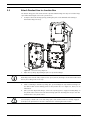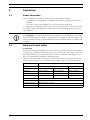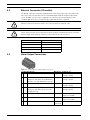
1
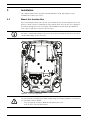
NEI-30 | VEI-30 Dinion Infrared Imager
NEI | VEI Series
en
Quick Install Guide
NEI-30 | VEI-30 Dinion Infrared Imager
Table of Contents | en
3
Table of Contents
1
Planning
4
1.1
Hardware Requirements
4
1.2
Pre-installation Checklist
5
2
Installation
6
2.1
Mount the Junction Box
6
2.2
Route Wires and Attach Connectors
7
2.3
Attach Pendant Arm to Junction Box
8
3
Connection
9
3.1
Power Connection
9
3.2
Video and Control Cables
3.3
Ethernet Connection (IP models)
10
3.4
Alarm Output Connections
10
4
Configuration
11
4.1
Accessing the Controls
11
4.2
Adjusting the Focus and Focal Length
12
4.3
Making Pan Adjustments
13
4.4
Making Tilt Adjustments
13
4.5
Adjusting the Variable Field Illumination
14
4.5.1
Adjusting the LED Tilt Angle
14
4.5.2
Adjusting the Illumination Beam Width
14
Index
16
Bosch Security Systems, Inc.
9
Quick Install Guide
F.01U.166.250 | 1.0 | 2011.04
4
1
en | Planning
NEI-30 | VEI-30 Dinion Infrared Imager
Planning
CAUTION!
CLASS 1 LED PRODUCT
IEC60825-1 Ed. 1.2 (2001)
WARNING!
IMPORTANT MOUNTING INSTRUCTIONS
This apparatus must be securely attached to the wall in accordance with these installation
instructions. Failure to follow installation instructions may result in injury or death.
CAUTION!
Ensure that the selected location is protected from falling objects, accidental contact with
moving objects, and unintentional interference from personnel. Follow all applicable building
codes.
Select a suitable location that protects the camera from accidental damage, tampering and
environmental conditions exceeding the specifications of the camera.
Follow these mounting guidelines:
1.
Locate the camera such that it cannot be easily interfered with, either intentionally or
accidentally.
2.
Select a smooth, flat mounting surface to ensure proper sealing. The surface must also
support the combined weight of the camera and mounting hardware under all expected
conditions of vibration and temperature. Recommended mounting height is at least 4 m
(13 ft); however, optimal conditions will vary with the specific installation environment.
1.1
Hardware Requirements
Tools Required
–
1x 5 mm (3/16) hex key; 1x 4 mm (5/32) hex key (supplied)
–
Small, straight-blade screwdriver - 2.5 mm (0.1 in.)
–
Socket wrench and 9/16 in. (14 mm) socket
–
Drill and 7/32 in. (5.5mm) drill bit
Hardware Requirements
–
VEI-30 or NEI-30 junction box
–
Four (4) lag bolts, 1/4-9 x 2 (M7-0.35 x 50) with 1/2 in. head (not supplied)
–
Four (4) 1/2 in. (12 mm) washers (not supplied)
–
Two (2) 3/4 in. (20 mm) NPS watertight pipe fittings OR 1/2 in. (15 mm) NPS watertight
pipe fittings (not supplied)
F.01U.166.250 | 1.0 | 2011.04
Quick Install Guide
Bosch Security Systems, Inc.
NEI-30 | VEI-30 Dinion Infrared Imager
1.2
Planning | en
5
Pre-installation Checklist
WARNING!
This installation must be made by a qualified service person and must conform to all local
codes.
WARNING!
CSA Certified / UL Listed CLASS 2 power adaptors or Certified PoE+ rated 42.5 VDC to
57 VDC, 600 mA, 34.20 W (max) power adaptor must be used in order to comply with
electrical safety standards.
1.
Determine the location and distance for the junction box based on its voltage and current
consumption.
See Section 3 Connection, page 9, for wiring information and distances.
2.
Use only UL-listed liquid tight strain reliefs for conduits to the junction box to ensure that
water cannot enter the box. You must use 3/4 in. (20 mm) NPS watertight conduits and
fittings (to meet NEMA 4X standards).
WARNING!
Power and I/O cabling must be routed separately inside different permanently earthed metal
conduits.
3.
Route all rough wiring including: power, control, video coax, alarms I/O, relay I/O, and
fiber optic cabling. See Section 3 Connection, page 9, for video and control protocol
methods.
WARNING!
Install external interconnecting cables in accordance with NEC, ANSI/NFPA70 (for US
application) and Canadian Electrical Code, Part I, CSA C22.1 (for CAN application) and in
accordance with local country codes for all other countries.
CSA Certified / UL Listed CLASS 2 power adaptors must be used in order to comply with
electrical safety standards.
Branch circuit protection incorporating a 20 A, 2-pole Listed Circuit Breaker or Branch Rated
Fuses are required as part of the building installation. A readily-accessible 2-pole disconnect
device with a contact separation of at least 3 mm must be incorporated.
4.
Select the appropriate mounting kit to use, depending on the location of the VEI-30 / NEI30 Series camera. The camera is intended to be mounted securely to a wall using the
mounting holes in the junction box.
CAUTION!
Select a rigid mounting location to prevent excessive vibration to the camera.
Bosch Security Systems, Inc.
Quick Install Guide
F.01U.166.250 | 1.0 | 2011.04
6
2
en | Installation
NEI-30 | VEI-30 Dinion Infrared Imager
Installation
This chapter details how to mount the VEI-30 / NEI-30 to a wall. Any variations to the
installation procedures are noted.
2.1
Mount the Junction Box
Before mounting the junction box, decide if you should wire the box through the holes in the
bottom or back of the box. If wiring the box through the back, move the two (2) seal plugs to
the bottom through-holes before mounting. This installation must be made by a qualified
service person and must conform to all local codes.
NOTICE!
Use 3/4 in. (20 mm) NPS fittings for the holes on the bottom and back of the box. Use 1/2 in.
(15 mm) NPS fittings for the side holes.
Figure 2.1
Junction Box Wall Mount
WARNING!
The camera has been evaluated for wall mounting using the following hardware secured into a
2 x 4 stud under 1/2 in. drywall:
–
Four (4) Lag bolts, 1/4-9 x 2 (M7-0.35 x 50) with 1/2 in. head
–
Four (4) 1/2 in. (12 mm) flat washers
F.01U.166.250 | 1.0 | 2011.04
Quick Install Guide
Bosch Security Systems, Inc.
NEI-30 | VEI-30 Dinion Infrared Imager
Installation | en
1.
Locate a stud in the wall and mark the outside edges of the stud.
2.
Using the wall mount bracket as a template, align the mounting hole with the center of
7
the stud.
3.
Mark the point on the wall in the center of the hole where the mounting bolt will be
positioned.
4.
Remove the wall mount bracket and drill a pilot hole at the marked point.
5.
Align the wall mount bracket mounting hole with the hole drilled in the wall.
6.
Using a 9/16 in. (14 mm) socket and driver, secure the wall mount bracket by screwing
the 1/4-9 x 2 (M7-0.35 x 50) lag bolt with 1/2 in. (12 mm) washer securely into the stud.
7.
8.
Follow this procedure to attach the three remaining lag bolts.
Attach 3/4 in. (20 mm) NPS watertight pipe fittings (not supplied) to the bottom or back
holes of the junction box through which you will run the power, video, and control data
wires.
NOTICE!
The camera has not been evaluated for safety requirements using other mounting kits.
2.2
Route Wires and Attach Connectors
Power wires must be routed to the right (front) side of the junction box through a separate
conduit. All video, control, and alarm wires must be routed through a second conduit to the
left side of the box.
WARNING!
External interconnecting cables are to be installed in accordance with NEC, ANSI/NFPA70 (for
US application) and Canadian Electrical Code, Part I, CSA C22.1 (for CAN application) and in
accordance with local country codes for all other countries.
1.
Route all video, control, and alarm wires through the conduit fitting on the left side of the
junction box. See Section 3 Connection, page 9 for coax, UTP, and fiber optic
specifications and distances.
2.
Route the 24 VAC / 12 VDC lines through the conduit fitting on the right side of the box.
3.
Cut and trim all wires with sufficient slack to reach their connector terminals in the box,
but not so long as to be pinched. See Figure 2.2, Page 8, above, for the connector
locations.
4.
Attach the supplied 2-pin Power Plug to the incoming power wires.
5.
Attach the supplied 7-pin relay output plug to the incoming relay wires.
6.
Attach a BNC connector to the incoming video coax cable. If using UTP for video or
installing an Ethernet model, attach an RJ45 plug to the incoming UTP cable. If installing
a Fiber Optic model, attach an ST fiber plug to the fiber optic cable. See
Section 3 Connection, page 9, for the different methods of transmitting video and for wire
specifications.
Bosch Security Systems, Inc.
Quick Install Guide
F.01U.166.250 | 1.0 | 2011.04
8
2.3
en | Installation
NEI-30 | VEI-30 Dinion Infrared Imager
Attach Pendant Arm to Junction Box
The bottom hinge pin of the Camera Arm is provided with a Hinge Pin Stop to hold the hinge
open while attaching the arm to the junction box.
1.
Compress the bottom hinge pin by pushing the pin lever downward and rotating it
behind the Hinge Pin Stop.
Figure 2.2
2.
Camera Box Hinge Alignment
Open the top hinge by pushing its pin lever up and holding it.
NOTICE!
Both Hinge Pins must be fully compressed to open (unlock) the hinges of the Camera Arm and
before proceeding to the next step.
3.
While continuing to hold the top hinge pin, open and align the top and bottom hinges of
the Camera Arm to their mating points on the junction box. See Figure 2.2, above, for an
illustration.
4.
Once you have aligned the hinges, release the top hinge pin to engage its mating hinge on
the junction box. Then release the bottom hinge pin from the Hinge Pin Stop to lock the
Camera Arm to the junction box.
WARNING!
Serious injury or death can occur if the hinge pins of the Camera Arm are not fully engaged
(locked) to the junction box. Exercise caution before releasing the Camera Arm.
F.01U.166.250 | 1.0 | 2011.04
Quick Install Guide
Bosch Security Systems, Inc.
NEI-30 | VEI-30 Dinion Infrared Imager
Connection | en
3
Connection
3.1
Power Connection
9
Connect power from a 12 VDC or 24 VAC class 2 power supply as follows:
–
Use AWG 16 to 22 stranded wire or AWG 16 to 26 solid wire; cut back 5 mm (0.2 in.) of
insulation.
–
Loosen the screws of the supplied 2-pole connector and insert the wires.
–
Tighten the screws and insert the 2-pole connector into the power socket of the camera.
If the input voltage is not within the required range, the voltage indicator LED (on the front
face) will flash.
NOTICE!
For a DC supply, the polarity is important. Incorrect polarity does not damage the camera, but
will not allow the camera to switch on. If input voltage is not within the specified range or has
incorrect polarity (DC only), a yellow LED indicator in the front window pulses to indicate this
condition.
3.2
Video and Control Cables
Coaxial Cable
Coaxial cable terminated with BNC connectors is the most common method for transmitting
composite video. Bilinx control data can also be sent over the same cable. Bilinx is a Bosch 2way communication protocol that allows remote control, configuration, and updates over a
video coax cable. Bilinx is available on all analog models.
VEI-30 models feature cable compensation or “Pre-Comp,” which extends the range of video
from the head end, but does not extend the range of Bilinx control (n/a on NEI-30 models).
Cable Compensation
Maximum Distances
Video Only
Bilinx Control
Cable Type
Pre-comp OFF
Pre-comp ON
Pre-comp ON or OFF
RG-59/U
300 m (1000 ft)
600 m (2000 ft)
300 m (1000 ft)
RG-6/U
450 m (1500 ft)
900 m (3000 ft)
450 m (1500 ft)
RG-11/U
600 m (2000 ft)
1200 m (4000 ft)
600 m (2000 ft)
Size
O.D. between 4.6 mm to 7.9 mm (0.181 in. to 0.312 in.)
Shield
Copper braid: 95%
Central Conductor
Standard copper center
Terminal Connector
BNC
Bosch Security Systems, Inc.
Quick Install Guide
F.01U.166.250 | 1.0 | 2011.04
10
3.3
en | Connection
NEI-30 | VEI-30 Dinion Infrared Imager
Ethernet Connection (IP models)
The NEI-30 connects to a 10 Base-T/100 Base-TX network either directly or via a hub. Both
video and control are transmitted over a standard TCP/IP network using the built-in web
server. In addition, power can be supplied to IP camera models via the Ethernet cable
compliant with the Power-over-Ethernet Plus (IEEE 802.3at PoE+) standard.
CAUTION!
Ethernet connections must be made to non-exposed (indoor) networks only.
WARNING!
The IP camera models can accept power from the 12 VDC / 24 VAC power input or from the
Ethernet input. Ensure that the camera receives power from only one source.
3.4
Cable Type
CAT-5E or CAT 6 Ethernet
Maximum Distance
100 m (328 ft)
Bandwidth
10/100 Base-T Fast Ethernet
PoE+
IEEE 802.3at standard
Terminal Connector
RJ45
Alarm Output Connections
Figure 3.1
Terminal Block for Alarm Output Connections
# Label Description
Wire Color Connects To...
1 D1
Illuminator on alarm output connection 1 Black
Pin 1 of terminal block CN10
2 D2
3 T1
4 T2
Illuminator on alarm output connection 2 Orange
on single channel
Pin 2 of terminal block CN10
Voltage free and either open (Illuminator
on single channel
off mode) or closed (Illuminator on mode)
Tamper alarm output connection 1
Brown
Tamper alarm output connection 2
Gray
Pin 1 of terminal block CN11
on single channel
Pin 2 of terminal block Cn11
on single channel
Voltage free and either open or closed
5 V1
(normally closed)
Camera alarm output connection 1
White
Pin 6 of terminal block X453
6 V2
Camera alarm output connection 2
Yellow
on processor PCBA
Pin 3 of terminal block X453
7 NC
Not connected
(not
on processor PCBA
connected)
F.01U.166.250 | 1.0 | 2011.04
Quick Install Guide
Bosch Security Systems, Inc.
NEI-30 | VEI-30 Dinion Infrared Imager
4
Configuration | en
11
Configuration
All VEI-30 camera settings (except lens focus, focal length, and LED tilt) can be adjusted
remotely using the Configuration Tool for Imaging Devices (CTFID) software application. Refer
to the Configuration Tool for Imaging Devices User Manual located on the Bosch Security
Systems website (www.boschsecurity.com).
To adjust the focal length, focus, and the LED tilt, use the controls located on the access
panel on the rear of the camera housing. An access panel also contains the camera keypad
buttons that you use to interact with the camera’s on-screen display (OSD) menu. This menu
provides advanced set-up options for getting the best results under special circumstances.
4.1
Accessing the Controls
1.
Unscrew the two (2) captive screws (item 1, below) of the access panel on the rear of
the camera housing.
2.
Remove the sealing plug on the bottom left corner.
3.
Open the access panel. Now you can adjust the focus, focal length, and LED tilt controls
Figure 4.1 Rear camera housing with access panel
(see Figure 4.2 below).
Note: Before you make any adjustments, you may need to connect the camera to a
monitor to view the changes to the picture. See Section 3 Connection, page 9 for details.
Refer to the complete installation manual (on CD) for details about advanced camera
setup using the keypad controls.
NOTICE!
Remember to replace the sealing plug and tighten the captive screws on the panel when you
finish the adjustments.
Bosch Security Systems, Inc.
Quick Install Guide
F.01U.166.250 | 1.0 | 2011.04
12
en | Configuration
NEI-30 | VEI-30 Dinion Infrared Imager
Figure 4.2
1
2
3
4
4.2
Camera and LED
Focal length adjustment
Focus adjustment (zoom)
Advanced camera setup controls - keypad
LED tilt control
Adjusting the Focus and Focal Length
1.
2.
Use the top set screw (item 1, Figure 4.2) to adjust the image focus:
–
Turn the set screw to the left to focus toward (N) (near) (zoom in).
–
Turn the set screw to the right to focus toward (F) (far) (zoom out).
Use the lower set screw (item 2, Figure 4.2) to adjust the focal length (tight or wide):
–
Turn the set screw to the left for a wider focal length
–
Turn the set screw to the right for a telephoto (tight) focal length.
Figure 4.3
F.01U.166.250 | 1.0 | 2011.04
Focus and Zoom graphic on the inside of the access panel on the rear of the camera
housing.
Quick Install Guide
Bosch Security Systems, Inc.
NEI-30 | VEI-30 Dinion Infrared Imager
4.3
Configuration | en
13
Making Pan Adjustments
1.
Using the 4 mm hex key, loosen the bolts at the base of the “u bracket” to make the
necessary pan adjustments.
4.4
2.
When loosened, adjust the camera to the desired pan angle.
3.
Tighten the bolt to secure in place.
Making Tilt Adjustments
1.
Unscrew the round caps (CCW) where the bracket attaches to the camera housing to
expose the bolts for tilt adjustment.
2.
Using the 4 mm hex key, loosen the bolts and make the necessary tilt adjustments.
3.
Tighten the bolts to secure the camera in place.
4.
Replace the round caps when you finish the adjustments.
Figure 4.4 Example orientation: Camera rotated 90 degrees left, pointing up 50 degrees
Figure 4.5 Example orientation: Camera rotated 90 degrees right, pointing down 50 degrees
Bosch Security Systems, Inc.
Quick Install Guide
F.01U.166.250 | 1.0 | 2011.04
14
en | Configuration
NEI-30 | VEI-30 Dinion Infrared Imager
4.5
Adjusting the Variable Field Illumination
4.5.1
Adjusting the LED Tilt Angle
You can orient the LED array tilted either up or down to maximize infrared coverage over the
field of view. On the rear of the camera housing is graphic for the LED tilt.
Figure 4.6
LED tilt scale
The “+” symbol indicates adjusting the LED tilt angle above the camera axis; and the “-”
symbol indicates adjusting the LED tilt angle below the camera axis.
As a general guideline, when the camera is pointed at a steeper angle down (usually at higher
installation heights or for shorter range applications), the LED tilt angle should be raised
above the camera axis to reduce the potential of overexposure in the foreground.
4.5.2
Adjusting the Illumination Beam Width
You can adjust the infrared beam width by adding or removing the 3D diffuser. The 3D diffuser
is recommended for wider field of view applications. With the 3D diffuser, a focal length of 6
mm provides a horizontal field of view of 43° to match the illumination pattern; the resulting
beam angle is 43° (H) x 10° (V). Without the 3D diffuser, a focal length of 27 mm (or greater)
provides a horizontal field of view of 10° (or less) to match the illumination pattern; the
resulting beam angle is 10° (H) x 10° (V). Each camera ships a 3D diffuser plate (already
installed in the camera.) and the 3D diffuser (not installed in the camera). When inserted, the
3D diffuser will be held in place by the diffuser plate.
To install the 3D diffuser:
1.
Unscrew the four (4) captive screws beneath the illuminator in the front of the unit
(circled in Figure 4.7, below).
Figure 4.7
3D Diffuser (area circled)
2.
Using the captive screws, remove the 3D diffuser plate.
3.
Insert the 3D diffuser into the slit in the gasket on the 3D diffuser plate.
IMPORTANT: Ensure that the diffuser is inserted into the camera housing with the sticker
side facing the LED array. It is important that the diffuser is oriented with the sticker side
surface facing the LED array or IR performance will be lost.
4.
Install the diffuser and plate assembly into the camera housing to secure and seal the
unit.
F.01U.166.250 | 1.0 | 2011.04
Quick Install Guide
Bosch Security Systems, Inc.
NEI-30 | VEI-30 Dinion Infrared Imager
Configuration | en
15
To remove the 3D diffuser:
1.
Remove the 3D diffuser and plate assembly as when installing the 3D diffuser.
2.
Remove the 3D diffuser from the diffuser plate.
3.
Install the diffuser plate into the camera housing to secure and seal the unit.
Bosch Security Systems, Inc.
Quick Install Guide
F.01U.166.250 | 1.0 | 2011.04
16
en | Index
NEI-30 | VEI-30 Dinion Infrared Imager
Index
A
accessing controls 11
adjusting LED tilt angle 14
attaching
pendant arm 8
B
Bilinx 9
BNC connector
with pendant arm, corner or mast mount 7
C
cable compensation 9
CAT-5E 10
CAT-6 10
coaxial cable 9
configuration 11
control data I/O plug 7
E
ethernet 10
F
fiber optic
with pendant arm, corner or mast mount 7
H
hardware requirements 4
I
IEE 802.3af 10
installation 6
M
maximum distances 9
mounting 4, 6
N
NEMA Certification
for pendant arm, corner or mast mount 5
P
pendant arm
attaching to power supply box 8
power supply box
attaching to pendant arm 8
installing with pendant arm, corner or mast mount 6
Pre-Comp 9
R
routing wires
for pendant arm, corner or mast mount 7
U
unshielded twisted pair
with pendant arm, corner or mast mount 7
UTP CAT-5 10
W
wiring
for pendant arm, corner or mast mount 5
F.01U.166.250 | 1.0 | 2011.04
Quick Install Guide
Bosch Security Systems, Inc.
NEI-30 | VEI-30 Dinion Infrared Imager
Bosch Security Systems, Inc.
Index | en
Quick Install Guide
17
F.01U.166.250 | 1.0 | 2011.04
18
en | Index
F.01U.166.250 | 1.0 | 2011.04
NEI-30 | VEI-30 Dinion Infrared Imager
Quick Install Guide
Bosch Security Systems, Inc.
Bosch Security Systems, Inc.
850 Greenfield Road
Lancaster, PA 17601
U.S.A.
www.boschsecurity.com
© Bosch Security Systems, Inc., 2011