1
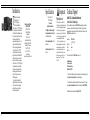
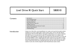
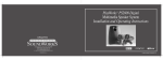
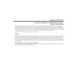
DeskTop Theater™5.1
DTT2500 Digital
Five Satellite/Subwoofer
Speaker System With Dolby Digital Processor
Installation and Operating Instructions
311 Needham Street, Newton, MA 02464
1-800-367-4434 Fax: 617-527-3194
www.hifi.com or e-mail us at [email protected]
Rev. A
0420000547
© 1999 Cambridge SoundWorks, Inc.
Safety & Regulatory Information
The following sections contain notices for various countries:
Notice for the USA
FCC Part 15: This equipment has been tested and
found to comply with the limits for a Class B digital
device, pursuant to Part 15 of the FCC Rules. These
limits are designed to provide reasonable protection
against harmful interference in a residential
installation. This equipment generates, uses, and can
radiate radio frequency energy and, if not installed
and used in accordance with the instructions, may
cause harmful interference to radio communications.
However, this notice is not a guarantee that
interference will not occur in a particular
installation. If this equipment does cause harmful
interference to radio or television reception, which
can be determined by turning the equipment off and
on, the user is encouraged to try one or more of the
following measures:
All cables used to connect the computer and peripherals
must be shielded and grounded. Operation with noncertified computers or non- shielded cables may result in
interference to radio or television reception.
Modifications
Any changes or modifications not expressly approved
by the grantee of this device could void the user’s
authority to operate the device.
Notice for Canada
Declaration of Conformity
According to the FCC96 208 and ET95-19
Name:
Address:
•
Creative Labs Inc.
1901 McCarthy Boulevard
Milpitas, CA. 95035
United States
Tel: (408) 428-6600
Directive 89/ 336/ EEC, 92/ 31/ EEC (EMC),
73/23/EEC (LVD)
declares under its sole responsibility that the product
This apparatus complies with the Class B limits for
radio interference as specified in the Canadian
Department of Communications Radio Interference
Regulations.
Trade Name:
Cet appareil est conforme aux normes de CLASSE “B”
d’interference radio tel que spe’cifie’ par le Ministère
Canadien des Communications dans les règlements
d’interfèrence radio.
has been tested according to the FCC / CISPR22/85
requirement for Class B devices and found compliant
with the following standards:
Model Number:
Creative Labs/
Cambridge SoundWorks
CSW3500
•
Reorient or relocate the receiving antenna.
•
Increase the distance between the equipment
and receiver.
This device complies with part 15 of the FCC Rules.
Operation is subject to the following two conditions:
•
Connect the equipment to an outlet on a
circuit different from that to which the
receiver is connected.
1. This device may not cause harmful interference,
and
•
Consult the dealer or an experienced
radio/ TV technician.
CAUTION: To comply with the limits for the Class
B digital device, pursuant to Part 15 of the FCC
Rules, this device must be installed with computer
equipment certified to comply with the Class B
limits.
Compliance
This product conforms to the following Council Directive:
EMI/ EMC: ANSI C63.4 1992, FCC Part 15 Subpart B
2. This device must accept any interference received,
including interference that may cause undesirable
operation.
Ce matériel est conforme à la section 15 des régles
FCC. Son fonctionnement est soumis aux deux
conditions suivantes:
WARNING: To prevent fire
or shock hazard, do not
expose this appliance to
rain or moisture.
1. Le matériel ne peut étre source d’interférences et
2. Doit accepter toutes les interférences reques, Y
compris celles pouvant provoquer un
fonctionnement indésirable.
Compliance Manager
Creative Labs, Inc.
March 4, 1999
Important Notice
The serial number for the DTT2500 Digital is
located on the Decoder Amplifier. Please write this
number down and keep it in a secure area. This is for
your security.
i
1-Year Limited Warranty
IMPORTANT SAFETY INSTRUCTIONS
READ INSTRUCTIONS - All safety and operating instructions should be read before the
DTT2500 Digital amplified subwoofer/satellite system is operated.
RETAIN INSTRUCTIONS - The safety and
operating instructions should be retained
for future reference.
HEED WARNINGS - All warnings on the
subwoofer and in the operating instructions should be adhered to.
FOLLOW INSTRUCTIONS - All operating
and use instructions should be followed.
CLEANING - Unplug the Power Supply
Adapter from the wall outlet or other power
source before cleaning. Do not use liquid
cleaners or aerosol cleaners. Use a damp
cloth for cleaning.
ATTACHMENTS - Do not use attachments
not recommended by Cambridge
SoundWorks as they may cause hazards.
WATER AND MOISTURE - Do not use the
Decoder Amplifier near water—for example, near a bath tub, wash bowl, kitchen
sink, or laundry tub; in a wet basement; or
near a swimming pool; and the like.
ACCESSORIES - Do not place the DTT2500
Digital Decoder Amplifier on an unstable
cart, stand, tripod, bracket, or table. The
Decoder Amplifier may fall, causing serious injury to a child or adult, and serious
damage to the product. Use only with a
cart, stand, tripod, bracket, or table recommended by Cambridge Sound-Works,
or sold with the product. Any mounting of
the satellites or subwoofer should follow
the manufacturer’s instructions, and
ii
should use a mounting accessory recommended by Cambridge SoundWorks.
VENTILATION - Slots and openings in the
Decoder Amplifier are provided for ventilation and to ensure reliable operation of
the Decoder Amplifier and to prevent it
from overheating. These openings must
not be blocked or covered. The openings
should never be blocked by placing the
product on a bed, sofa, rug, or other similar surface. The Decoder Amplifier should
not be placed in a built-in installation such
as a bookcase or rack unless proper ventilation is provided or Cambridge
SoundWorks’ instructions have been adhered to.
HEAT - The Decoder Amplifier should be
situated away from heat sources such as
radiators, heat registers, stoves, and other
products (including amplifiers) that produce heat.
POWER SOURCES - The Decoder Amplifier
should be operated only from the type of
power source indicated on the marking
label. If you are not sure of the type of
power supply to your home, consult your
product dealer or local power company.
For products intended to operate from
battery power, or other sources, refer to
the operating instructions.
POLARIZATION - The power supply may be
equipped with a polarized alternating-current line plug (a plug having one blade
wider than the other). This plug will fit into
the power outlet only one way. This is a
safety feature. If you are unable to insert
the plug fully into the outlet, try reversing
the plug. If the plug should still fail to fit,
contact your electrician to replace your
obsolete outlet. Do not defeat the safety
purpose of the polarized plug.
POWER-CORD PROTECTION - Power supply cords should be routed so that they are
not likely to be walked on or pinched by
items placed upon or against them, paying
particular attention to cords at plugs, convenience receptacles, and the point where
they exit from the Decoder Amplifier.
LIGHTNING - For added protection for the
DTT2500 Digital system during a lightning
storm, or when it is left unattended and
unused for long periods of time, unplug it
from the wall outlet. This will prevent damage to the Decoder Amplifier due to lightning and power-line surges.
OVERLOADING - Do not overload wall outlets, extension cords, or integral convenience receptacles as this can result in a
risk of fire or electric shock.
OBJECT AND LIQUID ENTRY - Never push
objects of any kind into the Decoder Amplifier through openings as they may touch
dangerous voltage points or short out parts
that could result in a fire or electric shock.
Never spill liquid of any kind on the speakers or the Decoder Amplifier.
SERVICING - Do not attempt to service the
any part of the DTT2500 Digital yourself
as opening or removing covers may expose you to dangerous voltage or other
hazards. Refer all servicing to qualified
service personnel.
DAMAGE REQUIRING SERVICE - Unplug
the power supply from the wall outlet or
other power source and refer servicing to
qualified service personnel under the following conditions:
a) When the power supply cord or plug is
damaged.
b) If liquid has been spilled, or objects
have fallen into the subwoofer.
c) If the Decoder Amplifier has been exposed to rain or water.
d) If the subwoofer does not operate normally by following the operating instructions; or exhibits a distinct change in performance.
e) If the product has been dropped or
damaged in any way.
REPLACEMENT PARTS - When replacement parts are required, be sure the service technician has used replacement
parts specified by Cambridge SoundWorks
or have the same characteristics as the
original parts. Unauthorized substitutions
may result in fire, electric shock, or other
hazards.
SAFETY CHECK - Upon completion of any
service or repairs to the DTT2500 Digital
system, ask the service technician to perform safety checks to determine that the
DeskTop Theater 5.1 system is in proper
operating condition.
WALL OR CEILING MOUNTING - The
DTT2500 Digital satellites should be
mounted to a wall or ceiling only as recommended by Cambridge SoundWorks.
Inside Asia
Creative Technology Ltd. Technical Support
31 International Business Park,
Creative Resource, Singapore 609921
Tel:
+65 8954100
Fax:
+65 8954999
BBS:
+65 776 2423
Operating Hours (Singapore Time)
Mon-Thu:
9am-6:30pm
Fri:
9am-6pm
Sat-Sun & Public Holidays:
Closed
o the original purchaser,
Cambridge SoundWorks, Inc.
(a division of Creative
Technologies, Ltd.) will
warrant the DeskTop Theater 5.1
DTT2500 Digital system to be free
of defects in material and
workmanship for a period of one
(1) year from date of purchase.
With respect to defects, Cambridge
SoundWorks will, at its option,
replace the product or repair the
defect in the product with no
charge to the original purchaser for
parts or labor.
This warranty does not extend to
any defect, malfunction or failure
caused by misuse, abuse, accident,
faulty hookup, defective associated
equipment or use of the speaker
with equipment for which it is not
intended.
T
This warranty is valid only when the
speaker is returned to the retailer that
sold the DeskTop Theater 5.1 DTT2500
Digital to the original purchaser.
This is the sole and express warranty.
This warranty is in lieu of all other
warranties, expressed or implied, of
merchantability, fitness for purpose or
otherwise. In no event shall Cambridge
SoundWorks be liable for incidental or
consequential damages or have any
liability with respect to defects other
than the obligations set forth as stated.
To ensure warranty coverage, it is
incumbent upon the original purchaser
of DeskTop Theater 5.1 DTT2500
Digital to inform the retailer of the
defect within the warranty period. The
only acceptable method of establishing
warranty status is
a copy of the original proof of purchase
indicating customers name and
purchase date.
© 1999 Cambridge SoundWorks, Inc. All rights reserved. Cambridge SoundWorks is a registered trademark, and PCWorks and DeskTop Theater are trademarks of Cambridge SoundWorks, Inc., Newton,
MA. The Creative logo and Sound Blaster logo are registered trademarks and the Environmental Audio logo and Creative Multi Speaker Surround are trademarks of Creative Technology Ltd. The Desktop
Theater 5.1 DTT2500 Digital Dolby Digital Decoder Amplifier is manufactured under the license from Dolby Laboratories. “Dolby”, “Pro Logic”, “AC-3”, and the Double-D symbol are trademarks of Dolby
Laboratories. Confidential unpublished works. Copyright 1992-1997 Dolby Laboratories, Inc. All rights reserved. Microsoft and DirectSound are registered trademarks of Microsoft Inc. All other brands and
product names are trademarks or registered trademarks of their respective holders. All specifications are subject to change without prior notice. Actual contents may differ slightly from those pictured.
20
Inside Europe
Creative Labs (Ireland) Ltd. Technical Support
Holland
Italy
Norway
Ballycoolin Business Park, Blanchardstown Dublin,
15 Ireland
Ireland
Tel:
Fax:
BBS:
Belgium
(for Benelux)
Tel:
Fax:
BBS:
Denmark
Tel:
BBS:
Finland
Tel:
BBS:
France
Tel:
Fax:
BBS:
Germany
(for Central and
Eastern Europe)
19
Minitel:
Tel:
Fax:
BBS:
+353 1 820 7555
+353 1 820 5052
+353 1 820 3784 (HST)
+353 1 820 3818 (ZyXEL)
+32 32300997 (French)
+32 32300998 (Dutch)
+32 3281 4631 (HST V.34)
+32 3281 4632 (V.34)
8001 7177 (Freephone)
+45 4824 4351 (HST V.34)
+45 4824 4361 (V.34)
08001 18052 (Freephone)
+45 4824 4351 (HST V.34)
+45 4824 4361 (ZyXEL 19,200)
+33 1 39 20 04 21
+33 1 39 20 90 10
+33 1 39 20 90 43 (HST)
+33 1 39 20 90 47 (V.32bis)
3615 CREATIVE and 3617 CREATIVE
+49 089 9579081
+49 089 9577453
+49 089 9577274
Scandinavia
Spain
Sweden
UK
Tel:
Tel:
Tel:
BBS:
+3115578244
+39 2 982 4 4100
800 11663 (Freephone)
+45 4824 4351 (HST V.34)
+45 4824 4361 (ZyTEL 19,200)
Tel:
Fax:
Tel:
Tel:
BBS:
+45 4824 4322
+45 4824 4323
900 953536 (Freephone)
020 791088 (Freephone)
+45 4824 4351 (HST V.34)
+45 4824 4361 (ZyTEL 19,200)
+44 01734 344 744
+44 01734 320 271
+44 01743 360 287
Tel:
Fax:
BBS:
Operating hours
Mon-Fri: Business Hours
Sat-Sun: Closed
Faxback is a facility that allows you to obtain product and technical information
through facsimile services. In Europe, use the following number: +353 1 820 3667.
DeskTop Theater 5.1
DTT2500 Digital
Contents
Declaration Of Conformity .................................................................................. i
Safety Precautions ............................................................................................ i, ii
Introduction ......................................................................................................... 1
Inspecting For Damage ........................................................................................ 2
Important Notes ................................................................................................... 2
Installation Sequence ........................................................................................... 3
Speaker Placement ............................................................................................... 3
Speaker Wire and Stand Installation ................................................................... 6
Attaching The Floor Stands ................................................................................. 7
Mounting The Speakers ....................................................................................... 7
Decoder Amplifier Functions .............................................................................. 8
Making Connections ............................................................................................ 8
Wiring Diagram ................................................................................................... 9
Connection to Sound Blaster Live! Via Digital DIN .......................................... 9
Decoder Amplifier Placement ........................................................................... 10
Surround Reference ........................................................................................... 12
Dolby Digital ................................................................................................. 12
Dolby Surround with Pro Logic .................................................................... 12
Creative Multi Speaker Surround .................................................................. 13
Audio Mode Selection ................................................................................... 13
Applications Guide ............................................................................................ 14
Specifications ..................................................................................................... 18
Important ............................................................................................................ 18
Technical Support .............................................................................................. 18
1-Year Limited Warranty .................................................................................. 20
iii
Introduction
hank you for purchasing
DeskTop Theater 5.1
DTT2500 Digital by
Cambridge SoundWorks.
DeskTop Theater 5.1 DTT2500 Digital
lets you experience the full potential
of Dolby Digital® multichannel sound
from your computer DVD player, with
a dynamic output that rivals a
component home theater system. It
processes both Dolby Digital and
Dolby Surround program material.
DeskTop Theater 5.1 DTT2500
Digital offers discreet four-channel
support for Microsoft® DirectSound® 3D
and its other derivatives. In some of
today’s best CD-based action games,
DeskTop Theater 5.1 DTT2500 Digital
can automatically decode the Dolby
Surround cut-scenes while offering
enveloping positional four channel
audio. It’s ready for the new era of
DVD-based games.
Also included is Creative Multi
Speaker Surround, which lets you hear
all of your favorite stereo program
material with a new and exciting
three-dimensional quality.
T
1
Specifications
Cambridge SoundWorks
1-800-FOR-HIFI
(1-800-367-4434),
8 AM to Midnight,
Eastern time
1 PM to 4 AM
Greenwich Mean Time
In Canada: 1-800-525-4434
Outside US or Canada:
Tel: 617-332-5936
Fax: 617-527-3194
www.hifi.com
or e-mail us at [email protected]
DeskTop Theater 5.1
DTT2500 Digital
Six-channel
Amplifier Specifications
Left, Right, Left Surround, Right
Surround amplifiers, each of four: 7
watts RMS per channel
Center Channel amplifier: 21 watts
per channel
Subwoofer amplifier: 20 watts per
channel
Important
Playback Levels
DDT2500 Digital is intended for
individual or small group listening and
will achieve surprisingly high output
levels. However, playing the system
continuously at overly loud, distorted
levels on heavy bass program material
may cause its internal fuse to blow.
The fuse can be replaced only by a
qualified representative. To avoid this
inconvenience and a possible nonwarranty repair charge, reduce the
playback volume when the system
shows obvious signs of stress, i.e. it
sounds “raspy,” “fuzzy,” and/or
“muddy.”
Technical Support
Inside U.S.A., Canada and Latin America
Creative Labs Inc. Technical Support
If you need technical assistance, call 405-742-6622. Technical support is available
seven days a week from 8:00 am to midnight, Central time. You can get the latest
program and driver updates from Creative Labs’ bulletin board, 24 hours a day. Call
405-742-6660; use modem settings:
Baud rate:
Data bits:
Parity:
Stop bits:
300 to 14400
(V.32/V.42 bis)
8
none
1
You can also send a FAX at 405-742-6633 or write us at:
Technical Support
Creative Labs, Inc.
1523 Cimarron Plaza
Stillwater, OK 74075
To reach Creative Technical support via the Internet, visit our technical support web
site at http://www.creativehelp.com, for troubleshooting help.
For information about this product and other Creative Labs’ products, visit Creative
Zone at http://www.soundblaster.com. Or, call Customer Service at 800-998-1000.
Faxback information is available by calling 405-372-5227.
18
Holder/Cap (2)
Satellites (5)
MUSI
MOVI
FOURPOIN STEREO
PRO LOGIC
DOLBY
DIGITA DIGITAL IN ANALOG IN LL
L
CREATIVE
MULTI SPEAKER
Supports (3)
R
DOLBY
AUDIO
MASTE
CENTE
SPEAKER
MUT
POWER
DTT 3500 DIGITAL
Quick Reference Guide
3 meter speaker wires (4)
SUBWOOFE
SURROUND
(5) Wall Mounting Hardware
Decoder Amplifier
Strips of 4 feet (5)
5 meter speaker wires (2)
SPDIF DIN Cable
RS
SUB
C
C
RS
SUB
LS
LS
R
L
L
R
Feet (3)
L
Examine each unit carefully for signs of
shipping damage. If there is any damage, do
not install the system. Consult the store
where you purchased the system or call the
appropriate Creative Technology, Ltd.
support group at the number listed at the
end of this publication. Save the shipping
carton and inserts in case you have to
transport the system later.
All the items shown in the illustration
should be included. If anything is missing,
notify the retailer.
R
Singing Karaoke on PC with SB
Live! only (with Creative
PlayCenter)
1. Connect your microphone to the
MIC IN of SB Live!.
2. Enable the Microphone source
in the Mixer.
3. Select one of the seven Karaoke
modes under Environment in
Creative Launcher.
4. Click the Audio Menu button on
the Creative PlayCenter to hear
only the music, i.e. with the
vocal portion masked out.
feet) long. Typically, the two satellites
with the longer cables will be used on
the surround channels, but the
satellites are otherwise identical. If
you need extra cable length for the
front channel satellites, use the pair
with the longer cables instead.
All the speakers are magnetically
shielded, but the subwoofer is not.
LS
Singing Karaoke on PC with SB
Live! and Creative PC-DVD
Decoder Card (with Creative
Navigator application)
1. Connect your microphone to the
MIC IN of SB Live!.
2. Enable the Microphone source
in the Mixer.
3. Select one of the seven Karaoke
modes under Environment in
Creative Launcher.
4. Press the AUDIO MODE button
of the DTT2500 Digital decoder
amplifier unit until you hear
only the music i.e. vocal
portion is masked out.
connection, to hear the clearest digital
audio available. Conventional 2channel sound cards such as Sound
Blaster 16 or the Sound Blaster AWE
series can also be used with DTT2500
Digital, but these cards will not
provide rear channel output when
playing games using DirectSound®3D
or its derivatives.
One pair of satellites has cables that
are 3 meters (9 feet) long. The other
pair has cables that are 5 meters (16
RS
Enjoying CD Audio on PC
Select the MUSIC mode by pressing
the Creative Multi Speaker Surround
(CMSS) button until the LED for
MUSIC mode lights up. This mode
creates an enveloping five-speaker
surround effect that enhances stereo
music.
These instructions assume you have
a DVD player with a coaxial Dolby
Digital (AC-3) output (for example, the
Creative Labs PC-DVD Encore).
These instructions also assume your
sound card supports processing of
DirectSound®3D, including front and
rear two-channel minijack line outputs
(like Creative Labs Sound Blaster PCI
series or Sound Blaster Live! series).
Sound Blaster Live! owners should
utilize the exclusive Digital DIN
SUB
Karaoke Music:
Important Notes
C
CD Audio Music:
Inspecting
For Damage
Tandem Audio Cable (Green and Black Miniplugs)
Support Extends (18)
17
Frames (2)
Desktop Stands for satellites (5)
Monitor Stand
SPDIF Cable (RCA to RCA)
Hook and Loop Fasteners (10)
Satellite Position Stickers
2
Installation Sequence
Speaker Placement
1. Read all of the instructions before
installing the speaker system.
2. Using the placement instructions as
a guide, position the satellites, the
center channel speaker and
subwoofer around your computer.
Install the Desktop Stands and
Floor Stands as appropriate. If you
wish to substitute a powered
subwoofer for the subwoofer that
comes with the DTT2500 Digital,
read Substituting a powered
subwoofer page 5.
3. Connect the satellite speakers,
center channel speaker, and
subwoofer to the back of the
Decoder Amplifier.
4. Connect the Dolby Digital output
of your digital program source
(typically a DVD player) to the
Dolby Digital input of the Decoder
Amplifier.
5. Connect your normal audio signal
sources via the Line In and Rear In
inputs. An owner of a Sound
Blaster Live! sound card with a
Digital DIN output should use the
supplied cable to connect it to the
Digital DIN input instead.
The Front Satellites. The left front
and right front satellites play stereo
music, the off-screen sounds of
video playback and the front
channels of four channel games.
These satellites should be placed
to the sides of your monitor (see
Diagram A). Be sure to have a clear
line of sight from your listening
position to these satellites. The
satellites intended for front
placement have 3 meters (9 feet) of
cable.
Install the satellite’s Desktop
Stands when using them on the
desktop (see page 6).
3
6. With the Decoder Amplifier’s
power switch “off”, connect the
power supply adaptor to the
Decoder Amplifier.
7. Turn on the power. Use the
SPEAKER TEST mode to position
and balance the speakers.
8. You may wish to experiment with
speaker placement briefly before
concealing the connecting cables
and making the installation more
permanent.
9. The unit is ready for you to enjoy.
Refer to the Quick Reference guide
for information about settings for
specific program sources like DVD,
CDs, Video CD and games.
The satellites may also be hung on the
wall behind the monitor using the screw
and wall anchors provided (see
“Mounting The Speakers”, page 7).
If you wish to save desktop space,
use the hook and loop fasteners to
attach the satellite speakers to the sides
of the computer monitor (see Diagram B).
The Center Channel Speaker. The
center channel speaker provides the onscreen effects and dialog in Dolby
Digital, Dolby Surround or Creative
Multi Speaker Surround modes. It
should be placed as close to the center
of your computer monitor as possible.
A
Playing Games:
Playing Multi-format DVD Games
These games have Dolby Digital or
Dolby Pro Logic movie clips mixed
with the actual game sequence.
Select the MUSIC or MOVIE mode
by pressing the Creative Multi
Speaker Surround (CMSS) button
until the LED for MUSIC or MOVIE
mode lights up.
Playing Microsoft DirectSound 3D
or Environmental Audio Games
1. Under CMSS on your DTT2500
Digital decoder amplifier, select
FOURPOINT to fully enjoy the
4-channel gaming experience
from Microsoft DirectSound3D
or Creative Environmental
Audio (EA) titles with a 4channel audio card.
2. For Sound Blaster Live! users,
enable the 4-Speaker configuration on your PC. Otherwise,
select FourPoint under CMSS on
your DTT2500 Digital decoder
amplifier unit.
Playing Conventional Games
Select MUSIC or MOVIE by pressing
the Creative Multi Speaker Surround
(CMSS) button until the LED for
MUSIC or MOVIE mode lights up.
B
MUSIC
MOVIE
FOURPOINT
STEREO
PRO LOGIC
DOLBY
DIGITAL DIGITAL IN ANALOG IN
CREATIVE
MULTI SPEAKER SURROUND
LL
RR
DOLBY SURROUND
AUDIO MODE
MASTER
CENTER
SPEAKER TEST
MUTE
POWER
DTT 3500 DIGITAL
SUBWOOFER
SURROUND
16
Playing VCD Movies:
Using PC-DVD player on PC
1. Disable the ‘Creative Multi
Speaker Surround’ (CMSS)
function by pressing the CMSS
button until all four LEDs are
off.
For VCD movies with Dolby
Surround-encoded stereo
program:
You can use the Dolby Pro
Logic decoder, by selecting PRO
LOGIC DIGITAL IN, to experience 5.1-channel movie
viewing.
For VCD movies:
You will have Digital 2.1
channel output. To enhance
the experience, enable the
Digital Pro Logic by pressing
the DOLBY SURROUND button
until the DIGITAL IN LED lights
up.
Using SoftMPEG player or
PlayCenter on PC
1. Select the MOVIE mode by
pressing the Creative Multi
Speaker Surround (CMSS)
button until the LED for MOVIE
mode lights up.
This mode lets you experience
the surround sound with 5.1channel output; all dialog and
central sounds will be heard
through the center speaker,
while music and off-stage
sounds are heard through the
other four satellites.
If you are using PlayCenter to play
the VCDs, disable all CMSS effects
in your PlayCenter - use only
DTT2500 Digital CMSS MOVIE
mode.
Using VCD player on TV
1. Connect Video Out of the VCD
player to Video Input of your
television.
2. Connect the Audio Out of the
VCD player to the Line In of
your DTT2500 Digital decoder
amplifier unit.
3. Select the MOVIE mode by
pressing the Creative Multi
Speaker Surround (CMSS)
button until the LED for MOVIE
mode lights up.
You can experience surround sound
instead of mono/stereo sound; all
dialog and central sounds will be
heard through the center speaker,
while music and off-stage sounds are
heard through the other four satellites.
There are many mounting
possibilities. The monitor stand can
be attached with hook and loop
fasteners to the top of the computer
monitor. It directs the sound down
towards the listener (see Diagram C).
If your computer monitor’s
construction directs the sound of the
center channel satellite towards you
without a stand, attach the satellite
directly to the top of the monitor,
using the hook and loop fasteners (see
C
D
Diagram D). Position the face of the
center channel so that it is as far
forward as possible.
Use a Desktop Stand to position a
center channel satellite in front of the
monitor. It directs the sound up
towards the listener (see Diagram E).
The Center Speaker may also be
hung on the wall behind the monitor
using the screw and wall anchors
provided (see “Mounting The
Speakers”, page 7).
The Rear Satellites. The rear
satellites provide the surround
effects in Dolby Digital, Dolby
Surround and Creative Multi
Speaker Surround modes. They also
provide the discreet rear sounds
produced in four channel gaming.
5 meters (16 feet) of cable is
provided with the two remaining small
satellites for more flexibility in rear
channel placement.
The rear satellites may be placed in
any convenient sites alongside the
listener, including sites slightly
forward of the listening location.
The rear satellites do not have to be
at exactly the same height, nor at the
E
F
15
same height as the front satellites.
If you have side walls close to your
listening position, excellent placement for the rear satellites is slightly
behind your listening position, slightly
above ear level (see Diagram F). The
satellites may be hung on the wall
using the screw and wall anchors
provided (see Mounting The
Speakers page 7).
Do not be concerned if this
placement is not practical. Any rear
satellite placement to the left and right
side of the listening position will
provide strong directional and
surround effects.
G
4
Applications Guide
The rear satellites may be installed on
their convenient floor stands. While
listening, the stands should be positioned
to the left and right of your listening
position (see Diagram G on the
previous page).
The Floor Stands are small enough
to be stowed underneath a desk when
not in use. See page 7 for floor stand
assembly instructions.
Larger work surfaces can accommodate both front and surround pairs of
satellites on their Desktop Stands. Try
the extreme corners of a desk using the
Desktop Stands (see Diagram H).
Also, you may attach the rear
satellites under a desktop or at the
sides of a desk using the hook and
loop fasteners (see Diagram I).
After you have positioned the rear
satellites, use the test sound to make
sure each speaker can be heard
clearly.
The Subwoofer. The subwoofer’s
optimum position is on the floor
against the wall under the computer
desk. The nearer the subwoofer is to
the corner of the room, the stronger
its maximum bass output will be. We
strongly recommend placing the
subwoofer on the floor (see Diagram J).
Leave at least 8 cm (3 inches) of
space between the subwoofer face
and a wall. Small objects in front of,
but not touching the subwoofer (table
legs, for instance) will have no effect
on its sound. If you have no
available floor space, the subwoofer
can be placed on a shelf, desktop or
other sites, but its maximum output
will be reduced. The subwoofer is not
magnetically shielded, so position it
at least 18 inches away from a
computer monitor.
Substituting a powered
subwoofer. You may substitute a
powered subwoofer for the subwoofer
that comes with the DTT2500 Digital.
Connect its line level input (typically
an RCA jack) to the dedicated
subwoofer output on the back of the
Decoder Amplifier, using a shielded
audio cable with RCA plugs on each
end. Refer to the powered
subwoofer’s User Manual for
adjustment procedures.
Playing DVD Movies:
Using PC-DVD player on PC
1. Disable the ‘Creative Multi
Speaker Surround’ (CMSS)
function by pressing the CMSS
button until all four LEDs are
off.
For movies with Dolby
Digital 5.1 (AC-3)
soundtracks:
This signal is detected automatically and the DOLBY
DIGITAL LED lights up. You
will experience Dolby Digital
5.1 channel output.
For two-channel movies
which are Dolby Surroundencoded carried within the
Dolby Digital compressed
bitstream:
The Dolby Pro Logic decoder
will automatically decode the
program for 5.1 channel movie
experience.
H
5
I
Using DVD player on TV
1. Connect Video Out of the DVD
player to Video Input of your
television.
2. Connect Dolby Digital compressed signal output from your
DVD player to the DOLBY
DIGITAL (AC-3) SPDIF IN of
your DTT2500 Digital decoder
amplifier unit.
3. Press the CMSS button until all
its three LEDs are off to disable
the Creative Multi Speaker
Surround (CMSS) function.
Digital
Audio
Analog
Audio
PC-DVD ROM Drive
MPC-to-MPC CD-Audio Cable
LINE IN
CD_IN
For movies with Dolby
Digital 5.1 (AC-3)
soundtracks:
This signal is detected automatically and the DOLBY
DIGITAL LED lights up. You
will experience Dolby Digital
5.1 channel output.
For two-channel DVD
movies which are Dolby
Surround-encoded:
The Dolby Pro Logic decoder
will automatically decode the
program for 5.1 channel movie
experience.
AUX_IN
MIC IN
LINE OUT
REAR OUT
4-Channel Sound Card
(e.g. Sound Blaster Live!)
Dolby Digital (AC-3)
SPDIF Out
DOLBY DIGITAL
(AC-3) SPDIF IN
LINE IN REAR IN DIGITAL
DIN
ANALOG
INPUT
SPEAKER OUTPUTS
C SUBWOOFER RS
LS
R
AUDIO_OUT
AUTO
15V
DC IN
L
Encore Dxr2 / PC-DVD MPEG2
Decoder Card (Luxsonar)
Connection Guide for DeskTop Theatre 5.1 DTT2500 Digital with Sound Blaster Live! and Creative PC-DVD system.
J
14
R
L
REAR
RIGHT
K
LS
LS
C
SUB
RS
R
DOLBY DIGITAL
(AC-3) SPDIF IN
C
SUB
LS
The Audio Mode selection feature
can only be used with the PCM digital
soundtrack of a Video CD or DVD
with a stereo soundtrack, not a DVD
encoded with Dolby Digital 5.1 sound
or Dolby Surround-encoded material.
If you have an analog program with
separate left and right channels (the
analog output of a CD ROM, or the
analog stereo output of a “software”
video CD, for instance), you will have
to use the balance control in your PC’s
audio software to mute the undesired
channel.
Diagram K: To connect the speaker
wire to each satellite, press one of the
spring-loaded tabs to expose the
connection hole. Insert the bare end of
the wire into the exposed hole, then
release the tab to lock the wire in place.
Connect wires with red bands to red tab
connectors, and unmarked wires to
black tab connectors.
Notes: Matching red wires to red
tabs and unmarked wires to black
tabs insures the speakers all play “in
phase”. “Out-of-phase” connections
will do no electrical harm, but the
overall sound quality will be greatly
reduced. You can substitute regular
18 gauge speaker wire to create
longer cables, if needed.
RS
The stereo soundtracks of some
movies on the Video CD (VCD
format) contain different languages.
For example, a two channel soundtrack
may contain Mandarin on the right
channel and English on the left
channel. The VCD program literature
should indicate the presence of duallanguage soundtracks. Similarly, some
movies in the DVD format will contain
dual-language soundtracks. DTT2500
Digital lets you select one of these
languages and play it through both the
Left and Right speakers.
If there is no indication of which
channel is which and you hear two
different language soundtracks during
stereo playback, select the “LL” and
“RR” settings until you find the
language soundtrack you want.
3. Remove the backing from the
remaining, longer “L” label and wrap
it around the opposite end of the
speaker cable near the RCA-type plug.
4. Place the satellite in the front left
position.
5. Repeat this process using another 3
meter cable for the front right satellite,
using the “R” labels.
6. Connect another 3 meter cable to a
satellite. Use the “C” (center) labels.
If used, the Monitor Stand attaches to
the satellite in the same manner as the
Desktop Stands, although it does not
have a hole for the speaker wire.
Route the wire to the left or right side
of the attachment strut. Position the
satellite.
7. If you wish to use the Floor Stands
with the rear satellites, assemble the
stand according to Attaching The
Floor Stand instructions on page 7.
Use the RS and LS labels (right and
left surround) and 5 meter cables.
8. Connect the subwoofer using the last 3
meter cable to the “SUB” labels.
SUB
Unlike Pro Logic decoding, CMSS
Music, Movie and Four Point modes
are appropriate for use with multicoded sources such as DVD games. In
some game titles, the movie sequences
may be encoded in Dolby Surround
but the game sequences may be in the
WAV format. CMSS Movie mode
supports 6-channel output for .WAV,
.AVI, .MIDI and other audio software
formats. Few, if any of these kinds of
formats are Dolby Surround encoded.
The FOURPOINT mode passes the
four discreet channel audio of fourchannel games direct to each satellite
channel. It does not synthesize rear
channel output, so stereo signal in this
mode will play just through the front
two speakers and subwoofer.
The STEREO mode plays the Left
and Right Front speakers and the
subwoofer. It also lets you hear the
stereo downmix from any DVD.
Typically, the 3 meter speaker
cables will connect the front and
center satellites to the Decoder
Amplifier and the 5 meter cables
will connect the rear satellites to
the Decoder Amplifier. A panel of
twelve self-adhesive labels is
provided to identify each satellite
and subwoofer and the opposite
end of the cable connected to a
satellite and subwoofer.
1. Identify a 3 meter cable. Most
often, a satellite will be used with a
desktop stand. In this case, thread
the bare wire end of a 3 meter cable
through the hole in the desktop
stand. Connect this end to a
satellite (as shown in Diagram K).
Carefully insert the desktop stand’s
attachment arm into the socket in
the back of the satellite, taking up
any slack in the cable as required.
2. To use this satellite in the front left
position, remove the backing from
the small, round “L” label and
apply it to the back of the satellite
(see Diagram K).
C
CMSS is a 2-channel to 5.1-channel
sound processor similar in some aspects
to a Dolby Surround with Pro Logic
processor.
CMSS Music mode creates a
convincing 5.1 channel surround
soundfield with typical stereo sources,
whether they are Dolby Surroundencoded or not. It works well with Dolby
Pro Logic, WAVE, AVI and MIDI
program material. In essence, CMSS
Music mode puts you “on the stage”
for the music’s performance, surrounding you with the performers.
In a similar manner, CMSS Movie
mode provides the sonic impression of
being front and center at a movie
screening. Dialog and all normally
centered sounds from a stereo program
are heard through the center speaker. Use
this mode whenever a music program has
sounds you want to blend with on-screen
action or dialog.
Audio Mode Selection
R
Creative Multi Speaker
Surround (CMSS)
RS
Speaker Wire and Stand Installation
LINE IN REAR IN
DIGITAL
DIN
ANALOG
AUTO
INPUT
SPEAKER OUTPUTS
C SUBWOOFER RS
LS
R
15V
DC IN
L
L
13
6
Attaching The Floor Stands
Mounting The Speakers
The rear satellites may be installed
in their floor stands.
1. Insert the support into the
support extend.
2. Insert one end of a support
extend to the support. There are
nine support extends for each
floor stand to enable you to adjust
to a suitable height.
3. Insert a rubber foot into each of
the bottom-most support
extends.
4. Insert the rear cable through the
back of the holder/cap.
5. Connect the frame to stabilise the
floor stand.
6. Connect the cable to the satellite
speaker and attach the satellite to
the holder/cap.
7. Tuck the cable neatly into the
grooves available on any of the
support extends.
Screw Mounting: The Satellite and
Center Channel speakers may be
hung on a wall using an M5 screw
and their keyhole openings.
First attach four self-adhesive feet
to the back of each satellite (see
Diagram P) insuring a vibration-free,
secure installation. Leave about 3/8 of
an inch of the screw-head exposed to
fit into the back of the speaker.
Plastic anchors may be needed to
Satellite
Holder/cap
Support
Support extend
secure the screws into particularly
hard or soft material. If so, drill the
appropriate sized holes in the wall
and tap the anchors into the holes
until they are flush with the wall.
Insert the screws into the anchors
until they protrude 3/8 inch from the
wall.
Frame
P
Surround Reference
Dolby Pro Logic
Dolby Digital
Dolby Digital (earlier called AC-3)
delivers five discreet full-range
channels (left front, center, right front,
left surround and right surround) plus a
separate Low Frequency Effects (LFE)
channel.
Many soundtracks on the latest
generation laser discs, DVDs and High
Definition Television (HDTV), are
encoded with Dolby Digital technology.
When a 5.1 channel Dolby Digital
program source is playing, such as
from a Creative PC-DVD player, the
Dolby Digital indicator light will
illuminate automatically.
Note: Not every section of a DVD
will be 5.1-channel encoded. On many
DVDs, only the main movie program
will be available in 5.1 channel sound.
Other supporting chapters (like a
“Director’s Comment” section) may be
in stereo or mono. These sections will
not light the Dolby Digital indicator
even though the sound will be properly
reproduced by the DTT2500 Digital.
When listening to DVD movies with
5.1 channel Dolby Digital sound, be
sure to listen only to the digital program
source. You can insure this by:
1) making sure your DVD
player’s stereo downmix is
not sent to your soundcard. For
example, disconnect any cable
link between the cards.
2) making sure all four CMSS
indicator lights are off
(MUSIC, MOVIE,FOURPOINT
and STEREO)
3) muting the “CD” input of
your computer’s software mixer/
volume control application.
When playing a DVD game with a
mix of Dolby Digital 5.1 sound (a
digital signal at the SPDIF input) and
soundcard wavetable output (a signal at
the analog input), be sure to engage the
FOURPOINT mode in the CMSS settings.
Dolby Surround is an earlier
surround sound standard which is
decoded with a Pro Logic processor in
the DT2500 Digital. The Pro Logic
steering circuitry derives separate
center and rear channels from encoded
stereo program sources.
Pro Logic processing provides a
convincing movie soundfield when the
material is specifically encoded for
Dolby Surround. Most older stereo
movie soundtracks will only be
encoded for Dolby Surround, even
though the program source may be a
DVD’s digital output. Most DVDs
containing Dolby Surround program
material will cause both the Dolby
Digital and Digital Pro Logic lights to
illuminate. DTT2500 Digital will
decode these digitally transferred
Dolby Surround programs through the
digital Pro Logic decoder automatically.
CD-ROMs and CD’s with Dolby
Surround encoding will feature
the Dolby Surround logo at the
beginning of the program or on the
packaging. Process these programs by
making sure all CMSS indicator lights
are off and selecting the Pro Logic
Analog Input setting of the Surround
Mode button.
Do not select a Pro Logic decoding
mode if the program material is not
encoded for Dolby Surround.
Excessive center channel output will
result, and most stereo effect will be
lost. Use CMSS “Movie” or “Music”
modes to upmix stereo programs to a
realistic 5.1 channel sound field.
Foot
7
12
Then make sure the speakers are
positioned so that the test sound can
be clearly heard.
Finally, adjust the front panel level
controls for the center, subwoofer and
rear speakers. Adjust each control so
its speaker achieves a balanced
output level with the left and right
satellites (which provide a fixed
“reference” output level).
All Decoder Amplifier functions
except for the level controls are
disabled while the test sound is
running.
MUSIC
The speaker level controls operate at
all times. If desired, you may adjust
these controls during program material
to fine-tune the balance.
9. Mute: Mutes all output from the
DTT2500 Digital. Press the button once
to mute. Press a second time to restore
audio output.
The CMSS, Dolby Surround, Audio
Mode and Speaker Test buttons are
operable during mute.
PRO LOGIC
DOLBY
DIGITAL DIGITAL IN ANALOG IN LL
MOVIE FOURPOINT STEREO
Hook and Loop Fasteners: When
mounting speakers with hook and
loop fasteners, make sure that all
surfaces are clean and free of dirt
and grease. Hard, flat, unpainted
surfaces work best with hook and
loop fasteners (see Diagram Q).
Attach the fastener first to a
speaker. Then remove the
remaining backing and adhere to
the chosen surface.
Decoder Amplifier Making Connections
Placement
The Decoder Amplifier can be placed on
the desktop, a shelf or any site that makes
the controls convenient (see Diagram R).
The Power Adapter cord must be
able to reach from the Decoder Amplifier
back panel to your AC power receptacle.
Place the Decoder Amplifier on a hard,
flat surface.
There are ventilation slots on the bottom
and top of the Decoder Amplifier’s
enclosure. Don’t block the ventilation slots
by placing material on top of or below the
Decoder Amplifier.
R
Q
5
4
6
DOLBY SURROUND
CREATIVE
MULTI SPEAKER SURROUND
7
AUDIO MODE
8
SPEAKER TEST
R
9
MUTE
MUSIC
MOVIE
FOURPOINT
STEREO
PRO LOGIC
DOLBY
DIGITAL DIGITAL IN ANALOG IN
LL
RR
MUSIC
CREATIVE
MULTI SPEAKER SURROUND
DOLBY SURROUND
AUDIO MODE
MASTER
CENTER
SPEAKER TEST
MOVIE
FOURPOINT
STEREO
PRO LOGIC
DOLBY
DIGITAL DIGITAL IN ANALOG IN
LL
RR
MUTE
CREATIVE
MULTI SPEAKER SURROUND
DOLBY SURROUND
AUDIO MODE
MASTER
CENTER
SPEAKER TEST
MUTE
POWER
DTT 3500 DIGITAL
SUBWOOFER
POWER
SURROUND
DTT 3500 DIGITAL
CAMBRIDGE
SOUNDWORKS
SUBWOOFER
SURROUND
Consult the Wiring Diagram on
the next page before making any
connections.
Speaker Connections. Insert one
satellite’s plug into the corresponding Speaker Output on the Decoder
Amplifier. Repeat this process for
the remaining satellites and
subwoofer. If substituting a
powered subwoofer, connect it to
the SUBWOOFER LINE OUT.
Signal Connections.
Dolby Digital. Connect the Dolby
Digital/SPDIF output of your
signal source to the Decoder
Amplifier’s Dolby Digital input
using the cable with the RCA
plugs at each end.
For Sound Blaster Live! sound
cards with a digital I/O card:
Connect its Digital DIN output to
the Digital DIN input with the
supplied Digital DIN cable (the
one with the red plugs at each
end). It is not necessary to connect
a cable to the Line In and Rear In
input in this instance. Refer to
Connection to Sound Blaster Live!
via Digital DIN (next page) for
more information about this
connection.
For all other sound cards: Use the
tandem audio signal cable. Connect
the green stereo miniplugs to the
Line Out minijack output of your
sound card and to the Line In
minijack output of the Decoder
Amplifier. Connect the black stereo
miniplugs to the Rear Out minijack
output of your sound card (if
present) and to the Rear In minijack
input of the Decoder Amplifier.)
Power Supply Adapter Connections. Confirm the power switch is
in the “OFF” position. Insert the
power supply’s AC plug into an
appropriate receptacle. Insert the
small DC connector into the “15V
DC IN” receptacle on the back of
the Decoder Amplifier.
POWER
1
MASTER
2
CENTER
SUBWOOFER
SURROUND
3
11
8
Connection to Sound Blaster
Live! via Digital DIN
Wiring Diagram
DVD OUTPUT
(EXAMPLE: CREATIVE LABS
PC-DVD ENCORE Dxr2)
SOUNDCARD OUTPUT
(EXAMPLE: SOUND BLASTER LIVE!)
DOLBY DIGITAL
(AC-3) SPDIF IN
REAR
OUT
LINE
OUT
If your Sound Blaster Live! sound
card includes a Digital I/O card,
you can take advantage of the
clear, distortion-free audio
available from its Digital DIN
output.
1. Insert on end of the SPDIF cable
into the Digital DIN output jack
on the Sound Blaster Live!
Digital I/O card. The position of
the Digital DIN connector on the
Digital I/O card may be different
from this diagram. The Digital
DIN connector is the only
connector with a 9-pin configuration.
2. Insert the other end of the SPDIF
cable into the Digital DIN input
on the decoder amplifier.
3. Use the following procedure to
configure the Sound Blaster Live!
sound card for four speakers:
BLACK
GREEN
DIGITAL
OUTPUT
LINE IN REAR IN
DIGITAL
DIN
ANALOG
AUTO
INPUT
SPEAKER OUTPUTS
C SUBWOOFER RS
LS
R
15V
DC IN
L
POWER
SUPPLY
ADAPTER
RIGHT SURROUND
SATELLITE
SUBWOOFER
LEFT SURROUND
SATELLITE
SPDIF CABLE
DOLBY DIGITAL
(AC-3) SPDIF IN
LINE IN REAR IN
DIGITAL
DIN
ANALOG
AUTO
INPUT
SPEAKER OUTPUTS
C SUBWOOFER RS
LS
RIGHT SATELLITE
CENTER CHANNEL
SPEAKER
R
• Bring your mouse pointer to the top
of the monitor screen to display the
Creative Launcher.
• Click on AudioHQ.
• Click on the Speaker tab.
The speaker dialog box will appear.
• On the configuration tabbed page,
select the “4 Speakers” option.
• A sofa icon (representing you)
appears in the center of the preview
box, with four speakers at the corners
of the box.
• In some versions of Sound Blaster
Live! software, you can select the
“four-speaker” output option in the
Environment deck of the Surround
Mixer application (located in the
Sound Blaster Live! program tab of
the Creative Launcher).
Note: When the Analog/Auto switch is
pushed towards the Auto side, the
signal at the Digital DIN input is given
priority and the signal at the Analog
Audio inputs will be ignored. To listen
to a sound source through the analog
audio inputs, push the switch to the
Analog side.
L
15V
DC IN
DIGITAL I/O CARD DIGITAL DIN
Digital DIN Connector
Decoder Amplifier Functions
When the power is switched
“ON”, the green indicator lights on
the face of the Decoder Amplifier
will sequentially light from the left
to the right. The CMSS Music light
will remain illuminated after startup. The indicator light for Dolby
Digital will illuminate automatically
if a Dolby Digital program is
playing.
1. ON/OFF: Switches DeskTop
Theater DTT2500 Digital power on
and off.
An indicator light signals the power
is on.
2. Master: Adjusts the volume of
the entire system.
3. Center, Subwoofer and
Surround: These controls adjust the
level of the indicated channels. Their
output level should be balanced with
the fixed output level of the Left and
Right front speakers.
Top Row
4. Creative Multi Speaker Surround: CMSS processes analog
program material. Repeated presses of
this button steps through five
different operation modes.
Music: Creates a 5.1 speaker
soundfield appropriate for music from
any analog sound source.
Movie: Creates a 5.1 speaker
soundfield appropriate for movie or
game enjoyment from an analog
sound source.
FourPoint: Use this mode for DVD
games having Dolby Digital
soundtracks with Environmental
Audio Extensions or Microsoft®
DirectSound®3D for real-time
positioning of sound effects.
Stereo: Use this mode when you want
to hear just stereo effects or the stereo
Dolby Digital downmix of a DVD.
A Quick Reference Guide
is provided separately.
Consult this guide for
advice about playing
different program sources.
Slip it underneath the
Decoder Amplifier for
future use.
No lights illuminated: Mutes any
analog stereo or CMSS output. Use
this setting if you wish to play an
analog stereo signal through the
Dolby Pro Logic processor.
For more information about
Creative Multi Speaker Surround,
see page 13.
5. Dolby Digital indicator light:
This light turns on whenever a
Dolby Digital signal is detected at
the SPDIF input of the DTT2500
Digital. For Dolby Digital 5.1
sound reproduction, make sure only
this light is illuminated.
6. Dolby Surround: This button
cycles between Dolby Pro Logic
processing of the digital signal,
then the analog input and no Pro
Logic processing.
7. Audio Mode: Use this button to
play just the left or right channels
of a stereo digital signal (PCM
from an audio CD, a Video CD or a
stereo signal from a DVD). Use
this when, for example, a Video CD
has different languages on the left
and right channels.
Repeated presses of the button
selects which channel is fed to both
the Left and Right front speakers.
LL-Left channel to both Left and
Right front speakers.
RR-Right channel program to both
Left and Right front speakers. See
“Audio Mode Selection”, page 13
for further information about this
feature.
8. Speaker Test: Press this button
to start the “test sound” generator.
Use this test sound to position all
the speakers and to balance their
relative output.
The test sound moves in sequence
from the left satellite, the center
speaker, the right satellite, then to
the right surround satellite, left
surround satellite and the
subwoofer. All of the indicator
lights will blink on and off while
the test sound generator is in
operation.
The test sound will operate for
three complete cycles and then stop.
You can terminate the sound at any
point by pressing the Speaker Test
button again.
First use the test sound to verify
that each speaker is operating.
LEFT SATELLITE
DTT3500 Digital Decoder Amplifier
9
10