1
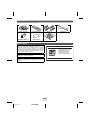
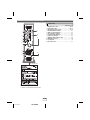
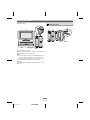
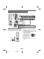
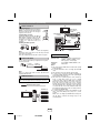
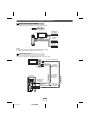
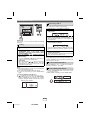
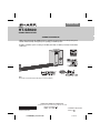
ENGLISH
MODEL
HT-SB600
SOUND BAR SYSTEM
OPERATION MANUAL
Thank you for purchasing this SHARP product. To obtain the best performance from this product, please
read this manual carefully. It will guide you in operating your SHARP product.
HT-SB600 Sound Bar system consisting of HT-SB600 (main unit), CP-SB600 (sound bar) and CP-SW600
(subwoofer).
TIMER
INPUT
HT-SB600
HDMI
ARC
3
2
1
TV
LINE
DIGITAL
2
1
2
1
TIMER
CLOCK
TUNER(BAND)
TUNING
DIMMER
MUTE
X-BASS
BASS/TREBLE
EQUALIZER
LEVEL
CENTER
LEVEL
SUBWOOFER
PRESET
VOL
VOL
PRESET
TV
VOL
INPUT
CHANNEL
Note:
This product is recommended for flat panel TV (LCD and plasma).
SHARP ELECTRONICS OF CANADA LTD.
335 Britannia Road East, Mississauga,Ontario L4Z 1W9
TINSEA363AWZZ
HT-SB600_Front EN.fm
PRINTED IN MALAYSIA
11E R KI 1
2011April18
Accessories
The following accessories are included.
AM Loop Aerial
Remote Control
Stand x 4
Wall Mount Angle x 2
Pattern Paper
Speaker Wire
FM Aerial
Special Notes
Manufactured under license under U.S. Patent Nos:
5,956,674; 5,974,380; 6,487,535 & other U.S. and
worldwide patents issued & pending. DTS, the Symbol,
& DTS and the Symbol together are registered
trademarks & DTS Digital Surround and the DTS logos
are trademarks of DTS, Inc. Product includes software.
© DTS, Inc. All Rights Reserved.
ENERGY STAR® Program Information
Products that have earned
the ENERGY STAR® are
designed to protect the
environment through
superior energy efficiency.
Manufactured under license from Dolby Laboratories.
Dolby, Pro Logic, and the double-D symbol are
trademarks of Dolby Laboratories.
HDMI, the HDMI Logo, and High-Definition Multimedia
Interface are trademarks or registered trademarks of
HDMI Licensing LLC in the United States and other
countries.
ENERGY STAR® is a U.S. registered mark.
1
2
3
4
5
6
7
1
9
E-1
2011 April 22
HT-SB600
Special Notes (continued)
VALID IN CANADA ONLY
LIMITED WARRANTY
Consumer Electronics Products
Congratulations on your purchase!
Sharp Electronics of Canada Ltd. (“Sharp”) warrants to the first purchaser for this Sharp brand product (“Product”), when shipped in its original container
and sold or distributed in Canada by Sharp or by an authorized Sharp dealer, that the Product will during the applicable warranty period, be free from
defects in material and workmanship, and will within the applicable warranty period, either repair the defective Product or provide the first purchaser a
replacement of the defective Product.
Conditions: This limited warranty shall not apply to:
(a) Any defects caused or repairs required as a result of abusive operation, negligence, accident, improper installation or inappropriate use as outlined
in the owner’s manual or other applicable Product documentation.
(b) Any defects caused or repairs required as a result of any Product that has been tampered with, modified, adjusted or repaired by any person other
than Sharp, a Sharp authorized service centre or a Sharp authorized servicing dealer.
(c) Any defects caused or repairs required as a result of the use of the Product with items not specified or approved by Sharp, including but not limited
to, head cleaning tapes and chemical cleaning agents.
(d) Any replacement of accessories, glassware, consumable or peripheral items required through normal use of the Product, including but not limited
to, earphones, remote controls, AC adapters, batteries, temperature probe, trays, filters, belts, ribbons, cables and paper.
(e) Any cosmetic damage to the Product surface or exterior that has been defaced or caused by normal wear and tear.
(f) Any defects caused or repairs required as a result of damage caused by any external or environmental conditions, including but not limited to,
transmission line/power line voltage or liquid spillage or acts of God.
(g) Warranty claims for Products returned with illegible or without appropriate model, serial number and CSA/cUL markings.
(h) Any Products used for rental or commercial purposes.
(i) Any installation, setup and/or programming charges.
How to get service: Warranty service may be obtained upon delivery of the Product, together with proof of purchase (including date of purchase) and a
copy of this limited warranty statement, to an authorized Sharp service centre or an authorized Sharp servicing dealer. In home warranty service may be
provided, at Sharp’s discretion, on any Sharp Television with the screen size of 40” or larger and on any Sharp Over-The-Range Microwave Oven or
Home Use Microwave Drawer. No other person (including any Sharp dealer or service centre) is authorized to extend, enlarge or transfer this warranty
on behalf of Sharp. The purchaser will be responsible for any and all removal, reinstallation, transportation and insurance costs incurred.
The express warranties in this limited warranty are, except for consumer purchasers domiciled in Quebec, in lieu of and, except to the extent prohibited
by applicable law, Sharp disclaims all other warranties and conditions, express or implied, whether arising by law, statute, by course of dealing or usage
of trade, including, without limitation, implied warranties or conditions of merchantability and/or quality, fitness for a particular use or purpose, and/or noninfringement. Limitations (not applicable to consumer purchasers domiciled in Quebec to the extent prohibited under Quebec law): (a) Sharp shall not
be liable for any incidental, special, consequential, economic, exemplary or indirect damages of any kind or nature (including lost profits or damages for
loss of time or loss of use or loss of data) arising from or in any connection with the use or performance of a Product or a failure of a Product, even if
Sharp is aware of or has been advised of the possibility of such damages; (b) the remedies described in this limited warranty constitute complete
fulfillment of all obligations and responsibilities of Sharp to the purchaser with respect to the Product and shall constitute full satisfaction of all claims,
whether based on contract, negligence, strict liability or otherwise. Some provinces may not allow the exclusion or limitation of certain damages, or limits
on the duration or voiding of implied warranties or conditions; in such provinces, the exclusions and limits herein may not apply. This limited warranty is,
except for consumer purchasers domiciled in Quebec, governed by the laws of the Province in Canada in which the purchaser has purchased the
Product. For consumer purchasers domiciled in Quebec this limited warranty is governed by the laws of Quebec.
WARRANTY PERIODS (calculated from the date of original purchase):
Parts & Labour (exceptions noted)
Audio Product
1 year
Blu-Ray Product
1 year
Projector
1 year
(lamp 90 days)
LCD TV
1 year
Microwave Oven
1 year
(magnetron component-4 additional years)
Air Purifier
1 year
Portable Air Conditioner
1 year
Plasmacluster Ion Generator
1 year
3D Glasses
1 year
Wirele ss LAN Adapter
1 year
To obtain the name and address of the nearest Authorized Sharp Service Centre or Dealer, or for more information on
this Limited Warranty, Sharp Extended Warranty Offers, Sharp Canada Products or Accessory Sales, please contact
Sharp:
By writing to Sharp Electronics Of Canada Ltd. at 335 Britannia Road East Mississauga, Ontario L4Z 1W9
Calling: at 905-568-7140
Visiting our Web site: www.sharp.ca
THIS LIMITED WARRANTY IS VALID ONLY IN CANADA
E-2
2011 April 22
HT-SB600
1
2
3
4
5
6
7
8
9
Precautions
General
Volume control
● Please ensure that the equipment is positioned in a
well-ventilated area and ensure that there is at least
10 cm (4") of free space along the sides, top and back
of the equipment.
10 cm (4") 10 cm (4")
10 cm (4")
The sound level at a given volume setting depends on
speaker efficiency, location, and various other factors. It is
advisable to avoid exposure to high volume levels. Do not
turn the volume on to full at switch on. Listen to music at
moderate levels.
Cooling fan
This unit is fitted with a cooling fan at the rear for improved
cooling. Do not cover the opening in this section with any
obstacles.
10 cm (4")
● Use the unit on a firm, level surface free from vibration.
● Keep the unit away from direct sunlight, strong
●
●
●
●
●
●
●
●
●
magnetic fields, excessive dust, humidity and
electronic/electrical equipment (home computers,
facsimiles, etc.) which generate electrical noise.
Do not place anything on top of the unit.
Do not expose the unit to moisture, to temperatures
higher than 60°C (140°F) or to extremely low
temperatures.
If your system does not work properly, disconnect the
AC power lead from the wall socket. Plug the AC power
lead back in, and then turn on your system.
In case of an electrical storm, unplug the unit for safety.
Hold the AC power plug by the head when removing it
from the wall socket, as pulling the lead can damage
internal wires.
The AC power plug is used as a disconnect device and
shall always remain readily operable.
Do not remove the outer cover, as this may result in
electric shock. Refer internal service to your local
SHARP service facility.
This unit should only be used within the range of 5°C 35°C (41°F - 95°F).
SHARP is not responsible for damage due to improper
use. Refer all servicing to a SHARP authorised service
centre.
Warning:
● The voltage used must be the same as that specified on
this unit. Using this product with a higher voltage other
than that which is specified is dangerous and may
result in a fire or other type of accident causing
damage. SHARP will not be held responsible for any
damage resulting from use of this unit with a voltage
other than that which is specified.
● To prevent fire or shock hazard, do not expose this
appliance to dripping or splashing. No object filled with
liquids, such as vases shall be placed on the apparatus.
E-3
2011 April 22
HT-SB600
Cooling fan
Caution:
● The unit will get warm whilst being used. Do not touch
the warm areas of the unit for prolonged periods to
avoid injuries.
● This unit is equipped with a special function which
protects the amplifier circuit from damages. When it is
activated, the sound switch is turned off. In this case,
set the unit to the stand-by mode and turn on again.
1
2
3
4
5
6
7
1
9
Controls and indicators
1
2
Front Panel
3
Reference page
1. Remote Sensor . . . . . . . . . . . . . . . . . . . . . . . . . . 15
2. Information Display . . . . . . . . . . . . . . . . . . . . . . . 16
3. Timer Indicator. . . . . . . . . . . . . . . . . . . . . . . . . . . 20
4. On/Stand-by Button. . . . . . . . . . . . . . . . . 16, 18, 22
5. Input Button . . . . . . . . . . . . . . . . . . . . . . . 12, 15, 17
6. Equaliser Button . . . . . . . . . . . . . . . . . . . . . . 16, 22
7. Volume Up/Down Button. . . . . . . . . . . . . . . . . . . 16
4
5
6
7
Display
1 2 3 4
5
AM FMST
X-BASS MUTING
7
8
AM FMST
X-BASS MUTING
DIGITAL
9
PL
6
10
DIGITAL
PL
Reference page
PCM
ARC
1. AM Indicator . . . . . . . . . . . . . . . . . . . . . . . . . . . .
2. FM Indicator . . . . . . . . . . . . . . . . . . . . . . . . . . . .
3. FM Stereo Indicator . . . . . . . . . . . . . . . . . . . . . .
4. FM Stereo Receiving Indicator . . . . . . . . . . . . . .
5. DTS Indicator . . . . . . . . . . . . . . . . . . . . . . . . . . .
6. PCM Indicator . . . . . . . . . . . . . . . . . . . . . . . . . . .
7. X-BASS Indicator . . . . . . . . . . . . . . . . . . . . . . . .
8. MUTING Indicator . . . . . . . . . . . . . . . . . . . . . . . .
9. Dolby Digital Indicator . . . . . . . . . . . . . . . . . . . .
10. Dolby Pro Logic II Indicator . . . . . . . . . . . . . . . .
11. Audio Return Channel Indicator . . . . . . . . . . . .
11
PCM
ARC
E-4
2011 April 22
HT-SB600
19
18
18
17
17
18
17
16
17
17
17
1
2
3
4
5
6
7
8
9
Controls and indicators (continued)
Rear Panel
Reference page
1. Digital Input Socket . . . . . . . . . . . . . . . . . . . . 13, 14
2. Line Input Socket . . . . . . . . . . . . . . . . . . . . . . 13, 14
3. FM 75 Ohms Aerial Socket . . . . . . . . . . . . . . 11, 12
4. AM Aerial Earth Terminal . . . . . . . . . . . . . . . . . . 11
5. AM Loop Aerial Terminal . . . . . . . . . . . . . . . . . . 11
6. Front Speaker Terminal . . . . . . . . . . . . . . . . . . . . 11
7. Centre Speaker Terminal. . . . . . . . . . . . . . . . . . . 11
8. Subwoofer Terminal. . . . . . . . . . . . . . . . . . . . . . . 11
9. HDMI (TV ARC) Output Socket . . . . . . . . . . . . . . 12
10. HDMI Input Socket . . . . . . . . . . . . . . . . . . . . . . . . 12
11. Cooling Fan . . . . . . . . . . . . . . . . . . . . . . . . . . . . . . 4
12. AC Power Lead. . . . . . . . . . . . . . . . . . . . . . . . . . . 11
9
1
2
3
4
10
11
5
6
7
12
8
The spec label (*)
1
2
3
4
5
6
7
1
9
The spec label illustration may be
different from the actual label used
(*) Label is located at the bottom of the unit
E-5
2011 April 22
HT-SB600
Controls and indicators (continued)
Sound Bar
FRONT VIEW
1
3
2
4
2
2
REAR VIEW
5
6
7
Reference page
5. Right Front Speaker terminal . . . . . . . . . . . . . . . 11
6. Centre Speaker terminal . . . . . . . . . . . . . . . . . . . 11
7. Left Front Speaker terminal . . . . . . . . . . . . . . . . 11
1. Left Front Speaker
2. Bass Reflex Duct
3. Right Front speaker
4. Centre Speaker
Subwoofer
FRONT VIEW
REAR VIEW
2
1
3
SUBWOOFER SYSTEM
Reference page
1. Bass Reflect Duct
2. Woofer
3. Speaker Terminals . . . . . . . . . . . . . . . . . . . . . . . . 11
E-6
2011 April 22
HT-SB600
1
2
3
4
5
6
7
8
9
Controls and indicators (continued)
Remote Control
1
Reference page
2
HDMI
ARC
3
1
2
1
2
1
CLOCK
TIMER
TV
4
DIGITAL
1. Remote Control Transmitter . . . . . . . . . . . . . . . . 15
2. On/Stand-by Button. . . . . . . . . . . . . . . . . . . . 16, 18
3. TV ARC Button. . . . . . . . . . . . . . . . . . . . . . . . 12, 17
4. DIGITAL 1-2 Button . . . . . . . . . . . . . . . . . . . . 15, 17
5. CLOCK Button . . . . . . . . . . . . . . . . . . . . . . . . 16, 19
6. TUNING Up/Down Button . . . . . . . . . . . . . . . . . . 18
7. Dimmer Button. . . . . . . . . . . . . . . . . . . . . . . . . . . 16
8. EQUALIZER Button . . . . . . . . . . . . . . . . . . . . . . . 16
9. X-BASS Button . . . . . . . . . . . . . . . . . . . . . . . . . . 17
10. Subwoofer Level Down Button. . . . . . . . . . . . . . 16
11. Subwoofer Level Up Button . . . . . . . . . . . . . . . . 16
12. Preset Up Button . . . . . . . . . . . . . . . . . . . . . . 18, 19
13. Volume Down Button. . . . . . . . . . . . . . . . . . . 16, 17
14. ENTER Button . . . . . . . . . . . . . . . . . . . . . 18, 19, 20
15. TV Operation Button . . . . . . . . . . . . . . . . . . . . 8, 20
16. HDMI 1-2-3 Button . . . . . . . . . . . . . . . . . . . . . 12, 17
17. Line 1-2 Button . . . . . . . . . . . . . . . . . . . . . . . 15, 17
18. TIMER Button. . . . . . . . . . . . . . . . . . . . . . . . . 19, 20
19. TUNER(BAND) Button . . . . . . . . . . . . . . . . . . 17, 18
20. MUTE/Speaker Output Selection Button . . . . . . 16
21. Bass/Treble Button . . . . . . . . . . . . . . . . . . . . . . . 17
22. Centre Speaker Level Up Button . . . . . . . . . . . . 17
23. Centre Speaker Level Down Button. . . . . . . . . . 17
24. Volume Up Button . . . . . . . . . . . . . . . . . . . . . 16, 17
25. Preset Down Button . . . . . . . . . . . . . . . . . . . 18, 19
16
3
LINE
17
2
5
18
6
DIMMER
TUNING
TUNER(BAND)
7
19
EQUALIZER
X-BASS BASS/TREBLE
MUTE
8
9
10
20
21
SUBWOOFER LEVEL
CENTER LEVEL
22
PRESET
11
23
12
VOL
VOL
24
13
25
14
PRESET
TV
15
INPUT
CHANNEL
VOL
TV Operation Buttons (Only SHARP TV):
On/Stand-by Sets the TV Input Select
Button
power to
Button (TV)
“ON” or
“STAND-BY”.
Volume Up
and Down
Buttons
1
2
3
4
5
6
7
1
9
Press the
button to
switch the
input source.
Turn up/down Channel Up Switch up/
the TV
and Down
down the TV
volume.
Buttons
channels.
Note:
Some models of SHARP TV may not be operable.
E-7
2011 April 22
HT-SB600
Speaker preparation
To mount the speaker on the wall
4 Screw the wall mount angle to the wall as shown in
Caution:
● Be very careful to prevent the speaker [ 2.0 kg (4.41 lbs.)]
from falling when mounting on the wall.
● Before mounting, check the wall strength. (Do not put
on the veneer plaster or whitewashed wall. The speaker
may fall.) If unsure, consult a qualified service
technician.
● Mounting screws are not supplied. Use appropriate
ones.
● Check all wall mount angle screws for looseness.
● Select a good location. If not, accidents may occur or
the speaker may get damaged.
● SHARP is not responsible for accidents resulting
from improper installation.
Driving screws
the illustration. (Total screw is 8 pieces)
Wall mount angle
Wall mount
angle
Wall
(screws x 4) surface
Wall surface
(screws x 4)
Wall
mount
angle
Wall surface
Note:
Make sure all screws are fully tightened. (screws are not
supplied)
Installing the speaker
SHARP designed the speakers so you may hang them on
the wall. Use proper screws (not supplied). See below for
size and type.
mount angle.
2 Slot the speaker into the wall mount angle.
3 Fix them securely.
3.2 mm (1/8")
5 mm
(3/16")
1 Align the wall mount slot at the speaker to the wall
9 mm (3/8")
Wall surface
Min. 22 mm (7/8")
Fixing wall mount angle
(Horizontal position)
1 Fix the pattern paper to the wall in horizontal
position as below.
509 mm
Wall surface 44 mm
29 mm
44 mm
29 mm
Falling prevention
Safety wires (not supplied) are useful to prevent the
speaker from falling off the table.
Pattern paper
2 Make a hole on the wall following the screw point
marks on the pattern paper by using a drill.
32 mm (1-1/4")
8-9 mm (3/8")
Wall surface
3 Fix a wall mount plug (not supplied) into the hole
using a hammer, until it is flush with the wall
surface.
32 mm (1-1/4")
8-9 mm (3/8")
Loop the safety wires (not supplied) into each hole as
shown and tie the safety wires to the LCD TV stand.
Wall surface
E-8
2011 April 22
HT-SB600
1
2
3
4
5
6
7
8
9
Placing the system
Installation image:
Placing the stand
Place the stand as shown.
TV
SUBWOOFER SYSTEM
SUBWOOFER
SYSTEM
Stand
SUBWOOFER SYSTEM
VCR
DVD player
Main Subwoofer
unit
Place the system as shown.
Remove the protective film covering the main unit and
subwoofer before turn on the system.
Notes:
● As the sound from the system is omni-directional, you can
place the speaker anywhere you like. However, it is
recommended to place it as close to the TV as possible.
● The front panel of the speaker is not removable.
Caution:
Do not change the installation direction when the unit is
turned on.
1
2
3
4
5
6
7
1
9
E-9
2011 April 22
HT-SB600
System connections
Make sure to unplug the AC power lead before making any connections.
Main unit
Subwoofer
FM aerial
Red
Green
White
AM loop
aerial
Sound Bar
Wall socket
AC 120 V ~ 60 Hz
SPEAKERS
–
+
FRONT
INPUT
CENTER
SUB
WOOFER
CAUTION:
TO PREVENT ELECTRIC SHOCK, MATCH WIDE BLADE OF PLUG TO
WIDE SLOT, FULLY INSERT.
Purple
Speaker and Subwoofer connection
Connect the wire without insulation tube to the minus (–)
terminal, and the wire with coloured insulation tube to the
plus (+) terminal. Make sure to match the coloured
insulation tube with terminal colour before connection.
Purple
INPUT
–
+
Caution
● Never mistake the FRONT, CENTER and the
SUBWOOFER terminals. The main unit or the
speakers may be damaged.
● If you use other speakers with an impedance lower than
that specified, the main unit may be damaged. Front
speakers: 4 ohms, Subwoofer: 4 ohms.
● Do not make a mistake when
SPEAKERS
connecting the right and the left
speakers. The right speaker is
R
the one on the right side when FRONT L
you face the unit.
CENTER
● Do not let the bare speaker SUBER
WOOF
wires touch each other.
INCORRECT
● Do not allow any objects to fall
into or to be placed in the bass
reflex duct.
● Do not stand or sit on the subwoofer/speakers. You may
be injured.
INPUT
E-10
2011 April 22
HT-SB600
1
2
3
4
5
6
7
8
9
System connections (continued)
TV
Aerial connection
Supplied FM aerial:
Connect the FM aerial wire to the FM 75
OHMS socket and position the FM aerial
wire in the direction where the strongest
signal can be received.
DVD, Blu-ray
disc player or
similar
FM
aerial
To HDMI (ARC) input
terminal
Supplied AM loop aerial:
Connect the AM loop aerial to the AM and
GND (Earth) terminals. Position the AM
loop aerial for optimum reception. Place
the AM loop on a shelf, etc., or attach it to
a stand or a wall with screws (not
supplied).
To HDMI output
terminal
To HDMI
output
terminal
Installing the AM loop aerial:
<Assembling> <Attaching to the wall>
To HDMI input
terminal
Screws (not supplied)
Wall
Note:
Placing the aerial on the unit or near the AC power lead
may cause noise pickup.
Place the aerial away from the unit for better reception.
Outdoor FM aerial
Use an outdoor FM aerial if you require better reception.
Consult your dealer.
75 ohms
Outdoor
coaxial cable FM aerial
HDMI cables are not supplied
To select HDMI 1, 2, 3 or TV ARC:
On main unit:
Press INPUT button repeatedly until
“HDMI1”, “HDMI2”, “HDMI3” or “TV
ARC” appears on the display.
On remote
Press HDMI1, HDMI2, HDMI3 or TV
control:
ARC button.
Notes:
● This unit supports HDMI which enables ARC (Audio
Return Channel).
● To enable ARC make sure to use High Speed HDMI
Note:
When an outdoor FM aerial is used, disconnect the
supplied FM aerial wire.
HDMI Connection
Caution:
Turn off all other equipment before making this connection.
The illustration below shows the flows of the signals.
Audio and Video signal
TV
DVD/Blu-ray
Game console
cable.
● This structure also needs TV that supports ARC.
● To listen to the sound from non-ARC-compatible TV,
connect the digital output from TV to this system digital
input terminal. (refer page 13)
● This unit can be operated (power on/off, volume up/
down or switch input source) via a TV or similar
component which supports HDMI CEC (Consumer
Electronics Control). If this does not work, it does not
mean this system is faulty. Refer to the operation
manual of the respective component on how to activate
the CEC. Example: Go to the Menu of the component
to search and turn on the CEC. Different brands may
have different naming for the CEC. For Sharp LCD TV,
it is named as AQUOS LINK.
● To watch 3D images, connect 3D-compatible TV and
video component (Blu-ray Disc player, etc.) to this
system.
Make sure to use High Speed HDMI cables and put on
the 3D glasses, otherwise 3D images may not be
viewed properly.
Digital tuner
E-11
2011 April 22
HT-SB600
1
2
3
4
5
6
7
1
9
Audio connections to TVs, DVD players, VCRs, etc.
Other connection (without HDMI)
The illustration below shows the flows of audio and video signals.
Audio signal
Video signal
TV
DVD/Blu-ray
Disc Player
VCR/Game
console
Digital tuner, etc.
Notes:
● Refer to the operation manual of the equipment to be connected.
● Fully insert the plugs to avoid fuzzy pictures or noises.
Connecting a TV, etc.
Connect to the TV using an optical digital audio cable or an audio cable.
TV
To audio output terminals
To optical
digital audio
output terminal
Main unit
To LINE IN 1 input
terminal
Optical digital
audio cable
(commercially
available)
Audio cable
(commercially
available)
To LINE IN 2 input terminals
E-12
2011 April 22
HT-SB600
Audio signal
To DIGITAL IN 1
(optical) input
terminal
Audio signal
To HEADPHONE
terminal
1
2
3
4
5
6
7
8
9
Audio connections to TVs, DVD players, VCRs, etc. (continued)
Connecting a DVD player, etc.
Connect to the DVD player with an optical digital audio cable or an audio cable.
To audio output
terminals
Blu-Ray/DVD Player/Digital tuner
To optical digital
audio output
terminal
To the TV (video)
Audio signal
Optical digital audio
cable (commercially
available)
Audio signal
To coaxial digital
audio output
terminal
Coaxial digital
audio cable
(commercially
available)
Main unit
To DIGITAL IN
1 (optical)
input terminal
To DIGITAL IN 2
(coaxial) terminal input
Audio cable
(commercially
available)
To LINE IN 2 input terminals
Note:
Connect the DVD video cable directly to the TV (refer to the operation manual for the DVD player).
Connecting a VCR, etc.
Connect to the VCR with an audio cable.
VCR
To audio output
terminals
To the TV
(video)
Main unit
Audio signal
To LINE IN 2
input terminal
Audio cable
(commercially
available)
Note:
Connect the VCR video cable directly to the TV (refer to the operation manual for the VCR player).
E-13
2011 April 22
HT-SB600
1
2
3
4
5
6
7
1
9
Remote Control (continued)
Audio connections to TVs, DVD
players, VCRs, etc. (continued)
To select DIGITAL IN 1 (optical input) or DIGITAL IN 2
(coaxial input) function:
On main unit: Press INPUT button repeatedly until
“DIGITAL 1” or “DIGITAL 2” appears on the
display.
On remote
Press the “DIGITAL 1” or “DIGITAL 2”
control:
button.
To select LINE IN 1 or LINE IN 2 function:
On main unit: Press INPUT button repeatedly until
“LINE 1” or “LINE 2” appears on the
display.
On remote
Press the “LINE 1” or “LINE 2” button.
control:
Notes concerning use:
● Replace the batteries if the operating distance is
reduced or if the operation becomes erratic.
● Periodically clean the transmitter on the remote control
and the sensor on the unit with a soft cloth.
● Exposing the sensor on the unit to strong light may
interfere with operation. Change the lighting or the
direction of the unit.
● Keep the remote control away from moisture, heat,
shock, and vibrations.
Test of the remote control
Point the remote control directly at the remote sensor on
the main unit.
The remote control can be used within the range
shown below:
Remote Control
Battery installation
Remote sensor
Use 2 “AAA” size batteries (UM/SUM-4, R3, HP-16 or
similar). Batteries are not included.
Plastic film covering can be removed or peeled off.
1 Open the battery cover.
2 Insert the batteries according to the direction
indicated in the battery compartment.
When inserting or removing the batteries, push them
towards the
battery terminals.
3 Close the battery cover.
HDMI
TV
E-14
HT-SB600
15° 15°
ARC
Caution:
● Replace all old batteries with new ones at the same
time.
● Do not mix old and new batteries.
● Remove the batteries if the unit will not be used for a
long period of time. This will prevent potential damage
due to battery leakage.
● Do not use rechargeable batteries (nickel-cadmium
battery, etc.).
● Installing the batteries incorrectly may cause the unit to
malfunction.
● Batteries (battery pack or batteries installed) shall not
be exposed to excessive heat such as sunshine, fire or
the like.
2011 April 22
8" - 20"
(0.2 m - 6 m)
1
2
3
1
2
3
4
5
6
7
8
9
General control
Volume control
Main unit operation:
Press the VOLUME + button to
increase the volume and the
0 1 2 ..... 99 100
VOLUME – button for
decreasing.
Remote control operation:
Press the VOL + button to increase the volume and the
VOL – button to decrease the volume.
HDMI
ARC
1
TV
2
DIGITAL
1
2
CLOCK
TIMER
DIMMER
EQUALIZER
3
LINE
1
TUNING
2
TUNER(BAND)
X-BASS BASS/TREBLE
SUBWOOFER LEVEL
MUTE
CENTER LEVEL
PRESET
VOL
VOL
VOL
Muting
VOL
To turn the power on
Press the ON/STAND-BY button on the main unit or the
remote control.
● The power turns on. If the power does not turn on,
check whether the AC power lead is plugged in
properly.
To set the unit to stand-by mode:
Press the ON/STAND-BY button again on the main unit or
the remote control.
The volume is muted temporarily
when pressing the MUTE button
on the remote control. Press again
to restore the volume.
Note:
When the unit is turned off and back on again, muting is
cancelled.
Equaliser
Press the EQ button on the main unit or EQUALIZER
button on the remote control repeatedly to select the
desired equaliser mode.
Display brightness control
Press the DIMMER button to adjust the brightness of the
display.
Dimmer 1
(Display is dim)
Dimmer 2
(Display gets dimmer)
Dimmer off
(Display is bright)
MUTING
MUSIC
(for standard sound effect)
CINEMA /GAME
(for cinema/game sound effect)
SPORT
(for sport broadcasting)
NEWS
(for news)
DOLBY VS
(Dolby Virtual Speaker)
Subwoofer level control
Clock display
Clock can be displayed
during power On or standby
mode.
Display clock:
Press the CLOCK button on
the remote control. The time
display will appear for about 5
seconds.
To cancel the time display manually press the clock
button again within 5 seconds.
Note:
If clock not previously set, “ADJUST” will be displayed for
a whilst. (Refer “Setting the clock” on page 18)
Volume auto fade-in
If you turn off and on the unit with the volume set to 80 or
higher, the volume starts at 40 and fades in to the last set
level.
The subwoofer level can be
adjusted.
To increase the level, press
-5 -4 ..... +4 +5
the SUBWOOFER LEVEL
+ button.
To decrease the level, press the SUBWOOFER LEVEL
– button.
Notes:
● When sound from the speaker is distorted, decrease
the subwoofer level.
● When changing the subwoofer level, the output level of
the Subwoofer is also changed.
Centre speaker level control
The centre speaker level can
be adjusted.
To increase the level, press
the CENTER LEVEL + button.
HT-SB600
-4 .....
+4 +5
To decrease the level, press the CENTER LEVEL –
button.
Speaker output selection (HDMI connection)
Press and hold MUTE button on the remote control until
“TV SPK” or “SB SPK” appear on the display to toggle
sound output between this unit or TV.
E-15
2011 April 22
-5
1
2
3
4
5
6
7
1
9
General control (continued)
Bass control
Audio Return Channel (ARC) (Audio
Return Channel submenu)
1. Press the BASS/TREBLE
button to select “BASS”.
2. Within 5 seconds, press the
VOLUME (+ or –) button to
adjust the bass.
The audio return channel (ARC) enables an HDMI ARCcapable TV to send the audio stream to the HDMI OUT
socket of the receiver. To use this function, you must select
the TV ARC input and your TV must supports the ARC.
Dolby Virtual Speaker (DVS) sound mode
Treble control
The Dolby Virtual Speaker (DVS) creates virtual surrounds
comparable to the 5.1ch sound produced by the 3.1ch
speaker.
1. Press the BASS/TREBLE
button to select “TREBLE”.
2. Within 5 seconds, press the
VOLUME (+ or –) button to
adjust the treble.
When setting DVS to “ON” for 2 channel stereo signals,
Dolby Pro Logic II brings out virtual sound effects through
the signals converted into 5.1ch.
X-Bass control
Notes:
● Monaural signals do not generate surround effects.
● DVS equaliser effect may not be obtained depending
on signal types (the Dolby Virtual Speaker indicator
blinks). In this case, set the DVS mode to OFF.
When the X-BASS button on the
remote control is pressed, the X-BASS
unit will enter the extra bass
X-BASS
mode which emphasises the
bass frequencies, and X-BASS
indicator will appear. To cancel
the extra bass mode, press the
X-BASS or BASS/TREBLE
button.
DVS
Function
HDMI 1
HDMI 2
HDMI 3
TV ARC
The Dolby Virtual Speaker creates multichannellike sound effects.
Compared with the cinema mode, the bass
sound level is slightly reduced.
The Dolby Pro Logic II indicator also lights up if
2ch sound signals are detected.
● The DVS can be turned OFF by selecting other preset
DIGITAL 1
equaliser modes.
This product incorporates decoders supporting the Dolby
Digital system and DTS system.
AM
FM
FM ST
LINE 2
LINE 1
DIGITAL 2
On the main unit:
When pressing the INPUT button, the input source will
change. Press the INPUT button repeatedly to select
desired input source.
On remote control:
Press the LINE 1 or 2 button to select LINE IN 1 input or
LINE IN 2 input.
Press the DIGITAL 1 or 2 button to select DIGITAL IN 1
input or DIGITAL IN 2 input.
Press the HDMI 1 or 2 or 3 to select HDMI input.
Press the TUNER(BAND) button repeatedly to select tuner
function (FM ST/FM Mono/AM).
Press TV ARC button to select TV ARC.
Note:
The backup function will protect the memorised function
mode for a few hours should there be a power failure or the
AC power lead becomes disconnected.
Auto power on function:
When you press any function button on the remote control,
the unit will turn on.
Auto power off function:
The unit will automatically go to stand-by mode if:
1. No signal is detected within 20 minutes.
2. No reception of tuner broadcast signal within 20
minutes.
E-16
2011 April 22
HT-SB600
DTS (Digital
Theatre
Systems)
One of the digital audio systems for
theatrical use. As the sound quality is
emphasised, you can enjoy the realistic
sound effect in the home theatre system.
Lights up when detecting DTS signal.
Dolby Digital One of the digital audio systems for
theatrical use. You can also enjoy the
stereophonic effect in the home theatre
system.
Lights up when detecting Dolby Digital
signal.
Dolby Pro
System expanding 2ch stereo sound to
Logic II
more spacious sound. When setting
Dolby Virtual speaker to “ON”, Dolby Pro
Logic II is activated to enjoy the stereo
sound effect.
Lights up when Dolby Pro Logic II is
activated.
PCM
This is a general term for digitally
(Pulse Code encoded audio signals on a CD or DVD.
Modulation) This unit lets you enjoy playback of digital
signals from sources such as CD or DVD.
The indicator lights up when a PCM
signal is detected.
1
2
3
4
5
6
7
8
9
Listening to the radio
Memorising a station
HDMI
ARC
1
2
1
2
1
CLOCK
TIMER
TV
DIGITAL
DIMMER
EQUALIZER
You can store 40 FM and AM stations in memory and recall
them at the push of a button. (Preset tuning)
3
LINE
TUNING
2
1 Perform steps 1 - 3 in “Tuning” on page 17.
TUNER(BAND)
X-BASS BASS/TREBLE
2 Press the ENTER button to enter the preset tuning
MUTE
saving mode.
TUNING
3 Within 5 seconds, press the PRESET (
or
)
buttons to select the preset channel number.
Store the stations in memory, in order, starting with
preset channel 1.
Note:
This product can receive FM stereo/FM monaural/AM
broadcasts.
4 Within 5 seconds, press the ENTER button to
store that station in memory.
Tuning
If the preset number indicators disappear before the
station is memorised, repeat the operation from step
2.
1 Press the ON/STAND-BY button to turn the power
on.
2 Press the INPUT button on the main unit or
5 Repeat steps 1 - 4 to set other stations, or to
TUNER(BAND) button on the remote control
repeatedly to select the desired frequency band
(FM Stereo/FM Mono/AM).
change a preset station.
When a new station is stored in memory, the station
previously memorised will be erased.
3 Press the (TUNING
or ) button to tune in to
the desired station.
Manual tuning:
Press the (TUNING
or ) button as many times as
required to tune in to the desired station.
Auto tuning:
When the (TUNING
or
) button is pressed for
more than 0.5 seconds, scanning will start
automatically and the tuner will stop at the first
receivable broadcast station.
Notes:
● When radio interference occurs, auto scan tuning may
stop automatically at that point.
● Auto scan tuning will skip weak signal stations.
● To stop the auto tuning, press the TUNING button
again.
Note:
The backup function protects the memorised stations for a
few hours should there be a power failure or the AC power
lead become disconnected.
To recall a memorised station
Press the PRESET (
or
) button for less than 0.5
seconds to select the desired station.
To erase entire preset memory
1. Hold the TUNER(BAND) button on the remote control
for 4 seconds or more.
2. Whilst “CLEAR” is flashing, press the ENTER button.
To receive an FM stereo transmission:
● “
” will appear when an FM broadcast is in stereo.
● If the FM reception is weak, press the TUNER(BAND)
button to extinguish the “ST” indicator. The reception
changes to monaural, and the sound becomes clearer.
FM stereo mode indicator
FMST
FM stereo receiving indicator
E-17
2011 April 22
HT-SB600
1
2
3
4
5
6
7
1
9
Setting the clock (Remote Control only)
Timer operation (Remote Control only)
By setting the unit to the correct time, you can use it not
only as a clock but also for timer.
Setting the timer
In this example, the clock is set for the 12-hour (AM 12:00)
display.
SUBWOOFER LEVEL
CENTER LEVEL
PRESET
1 Press the CLOCK button. If clock is not set
VOL
“ADJUST” will blink. Within 5 seconds, press the
ENTER button.
VOL
PRESET
TV
2 Press the
or
button to select 12-hour or
24-hour display and then press the ENTER button.
“AM 12:00”
“AM 0:00”
“0:00”
The 12-hour display will appear
(AM 12:00 - PM 11:59)
The 12-hour display will appear
(AM 0:00 - PM 11:59)
The 24-hour display will appear
(0:00 - 23:59)
You can use the unit as an alarm clock by setting the timer.
Before setting timer:
1. Set the unit to the correct time (page 18).
If it is not set, you cannot use the timer function.
2. Prepare the sound source for playback.
3. Store radio stations (page 17).
1 Turn the power on and press the TIMER button.
Set the unit to the correct time if “STANDBY” does not
appear.
3 Press the
or
button to adjust the
hour and then press the
ENTER button.
2 Within 10 seconds, press the
or
button to
select “TIMER SET”, and press the ENTER button.
● Press the
or
button once to advance the time
by 1 hour. Hold it down to advance continuously.
● When the 12-hour display is selected, “AM” will
change automatically to “PM”.
3 Press the
4 Press the
4 Press the
or
button to adjust the hour and
then press the ENTER button.
or
button to adjust the minutes
and then press the ENTER button.
or button
to adjust the minutes
and then press the
ENTER button.
● Press the
or
button once to advance the time by
1 minute. Hold it down to advance continuously (5
minutes interval).
● The hour will not advance even if minutes advance
from “59” to “00”.
● The clock starts from “0” second (seconds are not
displayed).
● The time display disappears after approx. 5 seconds.
The start time is set and the finish time (1 hour later)
will be displayed automatically.
5 Set the time to finish as in steps 3 and 4.
6 Switch input with the
or
buttons, and then
press the ENTER button.
To confirm the time display:
Press the CLOCK button. The time display will appear for
about 5 seconds.
Note:
“ADJUST” will appear or time will be displayed if the
CLOCK button is pressed when the AC power supply is
restored after a power failure or unplugging the unit. If
incorrect, readjust the clock as follows.
To readjust the clock:
Perform “Setting the clock” from step 1. If “ADJUST” does
not appear, step 2 (for selecting the 12-hour or 24-hour
display) will be skipped.
To change the 12-hour or 24-hour display:
1. Clear all the programmed contents. [Refer to “Factory
reset, clearing all memory” on page 21 for details.]
2. Perform “Setting the clock” from step 1 onwards.
HDMI 1
TUNER
HT-SB600
HDMI 3
LINE 2
TV ARC
DIGITAL 1
LINE 1 DIGITAL 2
● When you select the tuner, select a station by
pressing the
or
button, and then press the
ENTER button.
● If a station has not been programmed, “NOPRESET”
will be displayed.
7 Adjust the volume with the
or
button and
press the ENTER button.
Settings are displayed in order, and the unit will enter
the timer stand-by mode.
Caution:
This unit cannot set the timer of other equipment.
To perform the timer playback using other equipment, you
should also set the timer on the equipment separately.
E-18
2011 April 22
HDMI 2
1
2
3
4
5
6
7
8
9
Timer operation (Remote Control only) (continued)
After completing the setting
When the timer setting is
completed:
The unit is in the timer
playback stand-by mode.
TIMER
When the start time is
reached:
Unit starts automatically
and the volume
increases gradually.
The unit is operated by
the timer.
Timer LED indicator
flashes
When the finish time is reached:
The unit is set to the power stand-by mode
automatically.
To check the timer setting:
1. Whilst in the timer playback stand-by mode, press the TIMER
button.
2. Within 10 seconds, press the
or
button to select “TIMERCAL”,
and press the ENTER button.
The unit returns to the timer playback stand-by mode after the setting
contents are displayed in order.
Canceling the timer playback:
Timer playback is cancelled by turning the power on whilst in the timer
playback stand-by mode. The same operation can be performed in the
following procedure without turning the power on.
1. Press the TIMER button. “TIMEROFF” will appear.
2. Within 10 seconds, press the ENTER button. Timer playback will be
cancelled (the contents of the setting will not be cancelled.)
Reusing the timer:
Using the same setting;
The timer setting will be memorised once it is entered. To reuse the
same setting, perform the following operations.
1. Turn the power on and press the TIMER button. “STANDBY” will
appear. If it does not appear, set the unit to the correct time.
2. Within 10 seconds, press the ENTER button. After the setting
contents are displayed in order, the unit is set to the timer playback
stand-by mode.
Changing the setting;
Turn the power on, and repeat the operation from step 1 in “Setting
the timer” (page 18).
The timer setting is cancelled.
Operating the TV with the remote control
You can operate Sharp TVs with this system’s remote
control.
Other operable button
Input Select Button
Watching TV
Point the remote control at the TV.
1 Press the TV ON/STAND-BY button to turn on the
TV.
2 Pressing the TV CH
or
button enables TV
channel switching.
3 Press the TV VOL. + or - button to adjust the TV
volume.
E-19
2011 April 22
HT-SB600
1
2
3
4
5
6
7
1
9
Troubleshooting chart
Many potential problems can be resolved by the owner
without calling a service technician.
If something is wrong with this product, check the following
before calling your authorised SHARP dealer or service
centre.
Remote control
Symptom
● The remote control
does not operate
properly.
General
Symptom
● No sound is heard.
●
●
●
●
● The sound from
subwoofer is not well
balanced.
● Power turns off
suddenly.
● Are there any obstructions
turned on with the
remote control.
● Is the unit unplugged?
● The protection circuit may
from any computers or
mobile phones.
mode and then turn it back
on.
Symptom
● The radio makes
unusual noises
continuously.
TV or computer?
● Is the FM aerial or AM loop
Condensation
Sudden temperature changes, storage or operation in an
extremely humid environment may cause condensation
inside the cabinet or on the transmitter on the remote
control. Condensation can cause the unit to malfunction. If
this happens, leave the power on until normal playback is
possible (about 1 hour). Wipe off any condensation on the
transmitter with a soft cloth before operating the unit.
When this product is subject to strong external interference
(mechanical shock, excessive static electricity, abnormal
supply voltage due to lightning, etc.) or if it is operated
incorrectly, it may malfunction.
Video component, 3D
images may not be
displayed.
Check the operation
manual of the respective
component.
● HDMI cable not support 3D
image.
HT-SB600
Possible cause
● Is the unit placed near the
aerial placed properly?
Move the aerial away from
the AC power lead if it is
located nearby.
If such a problem occurs, do the following:
1. Set the unit to the stand-by mode and turn the power on
again.
2. If the unit is not restored in the previous operation,
unplug and plug in the unit again, and then turn the
power on.
E-20
2011 April 22
unit plugged in?
● Is the battery inserted?
If problem occurs during operation
be activated. Unplug and
plug in the power lead
again after 5 minutes or
more.
● Depending on the TV and
● Is the AC power lead of the
Tuner
connected correctly?
Connect the HDMI cable
correctly and then perform
the reset procedure.
● The power is not
displayed on the TV.
● The unit cannot be
● Is the HDMI cable
● Set the unit to the stand-by
● 3D images not
shining on the remote
sensor?
● Is the remote control for
another equipment used
simultaneously?
to the minimum or
maximum level?
● When a button is
turned on.
● Is there a strong light
● Is the subwoofer level set
● Move the speaker away
pressed, the unit
does not respond.
in front of the unit?
(selection) set properly?
Is the volume level set to
“0”?
Is muting activated?
Is HDMI compliant
equipment being used?
Is the HDMI cable
connected correctly?
Connect the HDMI cable
correctly and then perform
the reset procedure. (refer
page 22)
Do not connect or
disconnect an HDMI cable
whilst power is on. This
may lead to operation
problems.
● Noise is heard
during playback.
correct?
● Is the battery dead?
● Is the distance or angle
incorrect?
Possible cause
● Is the input signal
●
Possible cause
● Is the battery polarity
1
2
3
4
5
6
7
8
9
Troubleshooting chart (continued)
Error indicators and warnings
Factory reset, clearing all memory
Make sure to disconnect all output and input cables
attached to the unit before performing the factory reset.
1. Press the ON/STAND-BY button to enter the power
stand-by mode.
2. Whilst pressing the EQ button, press and hold the
ON/STAND-BY button until “RESET” appears.
When you fail to perform operations properly, the following
messages are displayed on the unit.
Display
Meaning
● Malfunction of the surround
circuit. Place the speaker
away from noise source and
plug the AC power lead into
another wall socket. (*)
or
or
or
Caution:
This operation will erase all data stored in memory
including clock, timer settings and tuner preset.
● When there is no input signal.
●
Maintenance
●
Cleaning the cabinet
or
Periodically wipe the cabinet with a soft cloth.
Caution:
● Do not use chemicals for cleaning (petrol, paint thinner,
etc.). It may damage the cabinet finish.
● Do not apply oil to the inside of each component. It may
cause malfunctions.
●
(Display blinks)
●
●
Play back the connected
equipment.
Non-standard signal. Cannot
be recognized.
Signals other than DOLBY
DIGITAL, DTS, Linear PCM
cannot be recognized.
Poor connection of the digital
audio input terminal.
Turn off the unit and check if
the cable is connected
properly.
When the protection circuit is
activated.
Timer indicator
(blinks red)
● The cooling fan at the rear of
(Shown for 2 seconds)
the unit does not run.
Unplug the AC power lead
and check if foreign objects
get caught around the cooling
fan. (*)
(*): Should the same message appear even if the speaker
is unplugged and plugged in, or is set to the stand-by
mode and on again, contact your local dealer where
you purchased the unit.
1
2
3
4
5
6
7
1
9
E-21
2011 April 22
HT-SB600
Specifications
As part of our policy of continuous improvement, SHARP
reserves the right to make design and specification
changes for product improvement without prior notice. The
performance specification figures indicated are nominal
values of production unit. There maybe some deviations
from these values in individual unit.
Main unit
Power source AC 120 V ~ 60 Hz
Power
88 W
consumption
Dimension
Width: 103 mm (4 - 1/2")
Height: 421 mm (16 - 9/16")
Depth: 395 mm (15 - 1/2")
Weight
5.6 kg (12.34 lbs)
Output power Front Left/Right:
RMS: 200 W (100 W + 100 W)
(10% T. H.D.)
RMS: 160 W (80 W + 80 W) (1% T.H.D.)
Centre:
RMS: 100 W (10% T. H.D.)
RMS: 80 W (1% T.H.D.)
Subwoofer:
RMS: 100 W (10% T. H.D.)
RMS: 80 W (1% T.H.D.)
Output
terminal
Input
terminal
Maximum
input power
Rated input
power
Impedance
Dimensions
Weight
Full Range speaker system
6.5 cm (2 -1/2") speaker
200 W
100 W
4 ohms
Width: 920 mm (36 - 1/4")
Height: 85mm (3 - 3/8")
Depth: 79 mm(3 - 1/8")
2.0 kg (4.41 lbs.)
Subwoofer
Type
Maximum
input power
Rated input
power
Impedance
Dimensions
Weight
Subwoofer system
16 cm (6 - 5/16") woofer
200 W
100W
4 ohms
Width: 114 mm (4 - 1/2")
Height: 421 mm (16 - 9/16")
Depth: 395 mm (15 - 1/2")
4.5 kg (9.92 lbs.)
1
2
3
4
5
6
7
8
9
FM: 87.5 - 108.0 MHz
AM: 530 - 1,710 kHz
E-22
2011 April 22
Type
HDMI™ output: (audio/video support up
to 1080p) x 1
Analogue input (LINE 1):
Stereo mini socket Ø 3.5 mm
100 mV / 47 kohms
Analogue input (LINE 2):
RCA type x 1pair (L/R)
500 mV / 47 kohms
Coaxial digital input (DIGITAL 2):
RCA type x 1
Optical digital input (DIGITAL 1):
Square type x 1
HDMI input: (audio/video support up to
1080p) x 3
Tuner
Frequency
range
Soundbar (Speaker Right / Centre / Left)
HT-SB600