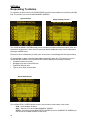
1
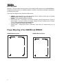
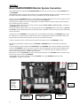
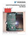
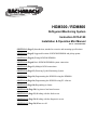
HGM300 / RDM800
Refrigerant Monitoring System
Instruction 3015-4149
Installation & Operation Mini Manual
Rev. 5 – November 2004
SECTION 1 (Page 2) Introduction, standard accessories and mounting specifications.
SECTION 2 (Page3) Suggested location of HGM300/RDM800 and pickup points.
SECTION 3 (Page 4) Wiring HGM300/RDM800.
SECTION 4 (Page6) Basic HGM300/RDM800 system connection.
SECTION 5 (Page 11) Multiple HGM connections.
SECTION 6 (Page 13) Powering Up the Monitoring System
SECTION 7 (Page 14) Programming the HGM300 using the RDM800.
SECTION 8 (Page 16) Programming the HGM300 using PC software.
SECTION 9 (Page 18) Responding to alarms.
SECTION 10 (Page 20) Log interval and trend screens.
SECTION 11 (Page 21) Working with the fault screen.
SECTION 12 (Page 24) Working with the diagnostic screen.
SECTION 13 (Page 26) Whom to call.
SECTION 1
Introduction
Welcome – This mini manual is an introduction to the installation and operation of the HGM300/RDM800
refrigerant monitoring system. For detailed installation / operation / maintenance information, please refer
to Instruction 3015-4148.
As you open the shipping carton locate the following items:
•
•
•
•
•
HGM300 – Manufactured to your order specifications, that is, number of zones, type of air sample
fittings and dual 4-20ma DC option (if ordered)
RDM800 – Remote Display Module (if ordered)
Charcoal filter with “T” bolt bracket; line end filter assembly (Quantity dependant on number of
zones ordered – for 4 zones, 5 filters; for 8 zones, 9 filters; 12 zones, 13 filters; and for 16 zones,
17 filters. Do not use a filter on the exhaust line)
Instruction manuals 3015-4148 and 3015-4149
Optional items – Audio/Visual alarms, visual alarm, audio alarm, air sample tubing, etc. as
ordered.
Proper Mounting of the HGM300 and RDM800
HGM300 Mounting Specs
RDM800 Mounting Specs
7.0"
7.0"
14.0"
9.0"
2
SECTION 2
HGM300 / RDM800 Refrigerant Gas Leak Monitor
Mechanical Room Placement
The HGM300 should be centrally located in the mechanical room and be readily accessible for easy
visual monitoring and servicing. Air sample tubing may be run in lengths up to 500 feet.
The fresh air purge line should draw from an area that does not contain any refrigerant gas and
cannot exceed 300 feet in length. The exhaust line should run to an out side location if possible.
The length of the exhaust line cannot exceed 300 feet.
Ideally, two to three pick up points spaced around each chiller will provide sufficient coverage. It may be
necessary to perform a “smoke” test of the mechanical room to determine the best locations. The smoke
test would provide the pattern of air currents present in the mechanical room.
Aux. Horn/Strobe
Remote Alarm
Exhaust Fan
Outside Hallway
Sample Inlet
Pickup Point
Machine Room
Picture of HGM300 alarm wiring)
Chiller
RDM800
Remote
Display
Module
HGM300
Halogen
Gas Monitor
Sample Inlet
The RDM800 should be mounted outside of the mechanical room, or at least just inside of a door to the
room. This is the “split architecture design” for safety of the operator. The RDM800 can be located up to
4500 feet from the HGM300. The RDM800 is the man machine interface by which you program the
HGM300, acknowledge alarms and observe conditions inside of the mechanical room. Note that there are
two additional alarm relay contacts in the RDM800 that can be programmed to alarm with “leak, spill,
evacuate, fault or monitor on”.
3
SECTION 3
Wiring the HGM300
AC Power (In / Out) -- RS485 -- 4-20 mAdc
Node Address
Switch
Dual 4-20 mAdc
Outputs
SIGNAL OUT
ONLY
On/Off Power
Switch
RS485
Main 120Volt Power
Auxiliary Power 120Volt
(Used to supply power for audio/visual alarms)
Dual 4-20 mA
Interface Board
P/N 3015-31333
Leak, Spill, Evacuate &
Fault alarm wiring block
4
Wiring the RDM800
HGM300 RS485
Connector
Terminator for
Building Automation
RS485 Connector
Building
Automation
System RS485
Connector
RDM800
relays
Main Power
Terminator for
HGM300 RS485
Connector
5
SECTION 4
Basic HGM300/RDM800 Monitor System Connection
Most applications for the Bacharach HGM300/RDM800 monitor systems will consist of a single HGM300 and a
single RDM800.
The HGM300 should be mounted in the mechanical room and the RDM800 should be located in a control room, on
an outside wall of the mechanical room or at least, just inside the door to the mechanical room.
Connect power to the HGM300 using the two-lead connector on the far right bottom of the power supply PC board.
Make the ground connection to the screw post provided on the HGM300 door.
Auxiliary power to supply 120 VAC for wiring alarms is available from the second two-lead connector located to
the left of the main power connector.
Connect any alarms required to the four-relay connector marked “LEAK, SPILL and EVACUATE”. Connect the
“SYSTEM FAULT” relay if used.
The dual 4-20mAdc output connector is located on the left side of the HGM300 main PC board. This is a SIGNAL
OUT ONLY function. Both loops must be wired if this option is installed. If only one loop is used, the unused loop
must be shorted out.
Connect power to the RDM800 by removing the four screws holding the front panel to the RDM800 chassis. Turn
the front panel over and locate the two-lead connector on the far right bottom of the PC board. Make the line and
neutral connections and attach the ground to the screw post provided on the panel.
Connect any alarms to the two-relay connector located on the bottom center of the RDM800 PC board.
The RS-485 communication wiring between the HGM300 and RDM800 must be connected in the following
manner –
Locate the RS-485 connector marked “TO MONITOR” on the RDM800. This connector should be on the far-left
bottom of the RDM800 PC board. Connect one lead of a twisted shielded pair to the “B” connection point (the far
left point), note the wire color. Connect the second wire to the “A” connection point (the middle), note the wire
color. Connect the ground to the “GND” connection point.
Make the wire run to the HGM300 and connect the twisted shielded pair to the HGM300 RS-485 connector using
the same color code as used on the RDM800.
NOTE: With a basic system consisting of a single HGM300 and a single RDM800 the position of the
“Terminators” switches is not critical.
NODE
ADDRESS
SWITCH
DUAL 420MADC
OUTPUT
SIGNAL
OUT ONLY
MAIN
POWER
RS-485
CONNECTOR
6
ALARM & FAULT
RELAYS
AUXILIARY
POWER
HGM300 WIRING SCHEMATIC
OPTIONAL
DUAL LOOP
4-20 MADC
COMMON
ALARM RELAYS
5 AMP, 240 VDC
MAIN
PWR
BKR
COMMON
LOOP 1 ZONE
LOOP 2 PPM
RS485
B
A
GND
LEAK
SPILL
EVACUATE SYS FAULT
1C NO NC 2C NO NC 3C NO NC 4C NO NC
L N
L N
AUX
PWR
MAIN
PWR
GND
SPECIAL NOTE: TO ESTABLISH THE RS485 COMMUNICATION LINK WITH THE RDM800 OR WITH A BUILDING
MANAGEMENT SYSTEM, USE #18 GAGE AWG, MULTI-STRANDED, SHIELDED AND TWISTED PAIR, INSTRUMENT CABLE.
ENSURE THAT THE DRAIN WIRE IS CONNECTED TO THE GND TERMINAL AT BOTH ENDS.
7
HGM300 Relay Connector
4
Relay
#4
NC
Relay
#3
NO
NC
NO
Relay
#2
COMMON
NC
NO
COMMON
Relay
#1
3
COMMON
2
Fault
NC
1
Alarm
NO
Alarm
COMMON
Alarm
Horn
Strobe
Neutral
Main Power
Line
Neutral
Line
Aux. Power
Jumper the ‘Neutral’ of the auxiliary power connector to the ‘Common’ on the relay block.
Connect one end of strobe or horn to the ‘NO’ of whichever level of alarm is appropriate for application.
The other end of strobe or horn is connected to a 120VAC power source, or to the ‘Line’ of the auxiliary
power connector.
8
RDM800 INTERIOR VIEW
MAIN
POWER
RS-485 TO
MONITOR
RS-485 TO
HOST
RDM800
EXTERNAL ALARM
RELAYS
9
RDM800 WIRING SCHEMATIC
AUXILIARY ALARM RELAYS
5 AMP, 240 VAC
USER DEFINABLE
RS485
TO
MONITORS
RS485
TO
HOST
L N
B A GND
B A GND
C NO NC C NO NC
MAIN
PWR
GND
SPECIAL NOTE: TO ESTABLISH THE RS485 COMMUNICATION LINK WITH THE RDM800 OR WITH A BUILDING
MANAGEMENT SYSTEM, USE #18 GAGE AWG, MULTI-STRANDED, SHIELDED AND TWISTED PAIR,
INSTRUMENT CABLE. INSURE THE DRAIN WIRE IS CONNECTED TO THE GND TERMINAL AT BOTH ENDS.
10
SECTION 5
Multiple HGM’S
TERMINATOR
“IN”
RMD800
MULTIPLE HGM300’S WITH RDM800
NOTE – THE LAST HGM300 OR RDM800 ON EITHER END OF THE
NETWORK MUST HAVE THE TERMINATOR IN THE “IN” POSITION AND ALL
OTHER UNITS MUST HAVE THEIR TERMINATORS IN THE “OUT” POSITION.
NOTE – TOTAL LENGTH OF RS-485 CABLE CANNOT EXCEED 1500m. (Use
instrument cable 20 gage multistrand shielded and twisted pair – similar or equal
to Beldon cable #8762.)
RS-485
HGM300
UNIT 1
NODE 1
TERMINATOR
“OUT”
RS-485 CONNECTIONS BETWEEN HGM300’s
THE RDM800 AND HGM300 UNIT 4 TERMINATOR MUST BE IN THE “IN”
POSITION. HGM300 UNITS 1, 2, & 3 MUST BE IN THE “OUT” POSITION.
HGM300
UNIT 2
NODE 2
HGM300
UNIT 3
NODE 3
TERMINATOR
“OUT”
TERMINATOR
“OUT”
HGM300
UNIT 4
NODE 4
TERMINATOR
“IN”
Connecting To A Building Automation System
The HGM300 may be connected to a building automation via the RS-485 connector. The node address
switch on each HGM300 may be set from “0” to “16” in order to conform to the building automation
system requirements. Units set to a “0” or “1” address both respond to messages from the RDM800 as
address “1” therefore you should not have a unit set to “0” and another set to “1” on the same network. If
the HGM300 network is connected directly to a building automation system it may not be connected to
the RDM800. However, the RDM800 has two communications ports, an “upstream” port (labeled TO
BMS) and a “downstream port (labeled TO MONITORS). A BMS node may be connected to the upstream
RDM800 port while the downstream RDM800port talks to the HGM300’s. In this case, the BMS is talking
“through” the RDM800 to the HGM300’s, but not physically on the HGM300/RDM800 network.
Note – If the HGM300 is not at the end of the line in a series connection, then the terminator on the HGM
must be set to “OUT.” Also, each end of the network must have the terminator set to “IN”.
TERMINATOR
“OUT”
BMS
HGM300
NODE 1
TERMINATOR
“IN”
HGM300
NODE 2
TERMINATOR
“OUT”
HGM300
NODE 3
TERMINATOR
“OUT”
HGM300
NODE 4
TERMINATOR
“IN”
11
Multiple HGM’s Connected to a Building Automation System – Daisy Chain Fashion
BUILDING
AUTOMATION
SYSTEM
RS-485
HGM300
UNIT 1
NODE 1
TERMINATOR “IN”
HGM300
UNIT 2
NODE 2
HGM300
UNIT 3
NODE 3
HGM300
UNIT 4
NODE 4
TERMINATOR
TERMINATOR
TERMINATOR
TERMINATOR
“OUT”
“OUT”
“OUT”
“IN”
Node address may be set from ‘0” to “16” to allow building automation system to integrate the monitor
system into its system. (Note: Units set for address “0” and address “1” will both respond to address “1”
messages. Therefore, there should not be an address “1” and an address “0” unit on the same network.
12
SECTION 6
Powering Up the Monitoring System
(Warm up time is 15 minutes)
Start up checkpoints:
• All buttons on RDM800 “chirp” when pressed. (Contact the factory if they do not “chirp”)
• DO NOT plug any unused zones. During start up the software will pull a vacuum test to verify the
number of zones and a plugged zone will give a false count
• Communication connection between HGM300 and RDM800
• Check node address for the HGM300 (or multiple HGM300”s)
• Terminator positions
13
SECTION 7
Programming the HGM300 Using the RDM800
1) From the System Screen on the RDM800, press the button adjacent to “ZONES”.
System Screen
Setup Screen #1
2) Press button adjacent to ZONE 1. NOTE: Press button adjacent to “LOCATION”. Then using the
keypad left/right buttons to move across and the up/down buttons to enter alphanumeric data, enter a
location for zone one (up to 12 characters). Press “ENTER” to lock in data and allow you to move to
the next function.
3) Press the button adjacent to “REFRIGERANT”. Using the up/down keys, select the proper refrigerant
gas for this zone; then press “ENTER”.
4) Press the “DISTANCE” button. Use the left/right keys to move across and the up/down keys to enter
the length of tubing for this zone; then press “ENTER”. NOTE: To disable a zone, set the distance
to “0”.
5) Press “AVE TEMP”. This function is used to ‘standardize’ the readings to ‘Standard Temperature and
Pressure’ (STP, which is 1 atmosphere and 25 degrees C). This function is rarely if ever used. The
PPM readings displayed are inversely related (i.e., as temperature goes up, PPMs decrease) to the
temperature of the sample (and thus the sample area). If the sample area temperature does not vary
from standard temperature (i.e., 25°C or 77°F) significantly the PPM reading will not be greatly
affected. A 10°C (18°F) change in the area/sample temperature will result in ~3.5% change in the
PPM reading. The Ave temp. parameter can be used to compensate the PPM reading as the
sample/sample area temperature varies from “standard” temperature (25°C or 77°F). The adjustment
range is from –50 to +70 degrees C.
6) Use the left/right and up/down keys to change the temperature, and the “ENTER” key to complete the
action.
7) “CURRENT PPM” – This function cannot be accessed.
8) Press the “LOG INTERVAL” button only if the interval is to be reduced from the 1440-minute (once
every 24 hours) factory setting to a lower setting. (At the 1440 minute setting the HGM300 will record
the observed PPM level once every 24 hours. This can be reset to lower numbers to trend a problem
in a given zone.)
9) Press “MORE”. This takes you to the second zone setup screen.
14
Setup Screen #2
10) Press “LEAK LEVEL” button. Use left/right keys to move across and up/down keys to readjust leak
alarm PPM level to desired PPM level.
11) Press “SPILL LEVEL” button. Repeat as in step 8.
12) Press “EVACUATE LEVEL” Button. Repeat as in step 8.
NOTE: The evacuate level must be greater than or equal to the spill level, which must be greater
than or equal to the leak level.
13) Press “RESET PEAK” button. Use the to clear the previous peak PPM displayed for this zone.
This key is used to clear the peak PPM for this zone, which is displayed at the top of this screen. The
peak PPM gives the PPM level, time and date of the highest refrigerant readings since the unit was
last cleared (or started, if the reading has never been cleared). The peak PPM reading along with the
TREND DATA can be a powerful diagnostic tool in detecting small leaks before they become large
leaks.
14) To move to the next zone setup screen, press the right keypad button. Use the “BACK” button to
move to the first zone set up screen. Repeat steps 2 thru 13 to program the second zone. Repeat as
necessary for all zones in monitor.
15) To return to the SYSTEM SCREEN, press “QUIT” then press “SYSTEM”.
15
SECTION 8
Programming the HGM300 Using PC Software
NOTE 1: There are two versions of software and firmware. Version 1.0 generally is found in HGM300
serial numbers beginning with AJ00 to serial numbers beginning with AF01 and version 1.40 from serial
numbers beginning with AF01 forward. If an RDM800 is connected to the unit the version of the firmware
can be obtained from the HGM300 Main screen.
NOTE 2: The PC software uses COM1 by default. Therefore, the interface cable should be connected to
the port configured as COM1 on the PC. Also, no other software drivers or devices in the PC may control
COM1 when the HGM300 software is in use.
The connection is made through a standard “straight through” serial port connection. A three-wire
connection is used (RXD, TXD, and GND). No hardware flow control is used. The HGM300 software
automatically configures COM1 to match the HGM300 RS-232 communications parameters.
NOTE 3: Occasionally the laptop connection will not connect properly and only two beeps are heard and
the program times out. The cure for this is to disconnect the RS-232 cable and cycle power on both the
HGM300 and the laptop. After both the HGM300 and the laptop are up and running connect the RS-232
cable and start the software program.
1) Turn on power to HGM300 and allow it to warm up.
2) Connect RS232 interface cable to PC and RS232 port on the HGM300.
3) Insert software disk into PC.
4) Open the HGM300 software using Windows Explorer.
5) Upon start up, the program will immediately attempt to download data from the HGM300. Several
beeps can be heard as the program communicates with the HGM300.
NOTE: To move through the screen use the ARROW keys to move up, down, left and right.
6) Use the ENTER key to select options and the ESC key to back out of a selection.
7) Using the arrow keys go to EDIT – press Enter key – the EDIT Menu DROPS DOWN – select
SYSTEM – press ENTER key. The HGM “LOCATION” becomes highlighted. Press ENTER key to
move to the HGM TAG area, use the BACKSPACE key to remove the existing tag, then enter in a
new tag. Press ENTER and you are returned to “LOCATION.” Use the ARROW key to select the
next item to be addressed. You CANNOT change the “SN” or “FIRMWARE” items. Press the
ESCAPE key to return to the menu bar.
8) Go to EDIT – press ENTER, select “ZONES” and press ENTER key. You may now select a specific
zone to identify and set parameters. When “REFRIGERANT” is selected use the ARROW keys to
move up and down through the gas library to locate the gas type for that zone – HIGHLIGHT the gas
type and press ENTER.
9) To set the ALARMS – select EVAC LEVEL first, press ENTER use the BACKSPACE key to clear
previous setting and type in the new PPM level. Use the same method to set the SPILL LEVEL and
LEAK LEVEL.
10) To close or bypass a zone, set the DISTANCE to 0 feet.
NOTE: It is very important that any time you modify a parameter (zone, system or calibration) and
send it to the HGM300, please wait for the PC software to indicate that the download is complete
before continuing with any edits.
Saving an HGM300 Program to a Disk or to the ‘C’ Drive
Go to “FILE” on the software program screen. Select “PATH” using the arrow keys then press ENTER.
Change the “CURRENT PATH” to the desired drive and location. Select “SAVE SETUP,” type in the title
such as HGM # 1, then press ENTER.
Sending a saved setup to the HGM300
Select “PATH,” then enter the correct path for the saved program. Select “OPEN SETUP” – path and
setup name is displayed. Use the arrow keys to go to HGM and select “SEND SETUP,” then press
ENTER. The saved program will be sent to the HGM300.
16
USB Type Laptops
Some of the newer laptops have USB ports and no RS-232 9-pin ports. You will be required to purchase
a PCMCIA card that converts the laptop to RS-232. We recommend the PCMCIA card manufactured by:
SEALEVEL SYSTEMS, INC.
155 TECHNOLOGY PLACE
P. O. BOX 830
LIBERTY, SC 29657
PHONE – 864-843-4343
www.sealevel.com
Part number: PC- SIO-232 PCMCIA CARD
A straight-through RS-232 cable and a DB25-to-DB9 adapter will be required to connect to the HGM300.
17
SECTION 9
Responding To Alarms
To respond to an alarm from the SYSTEM SCREEN, press the button adjacent to the blinking ALARM
field. This will take you to the ALARM SUMMARY SCREEN.
System Screen
Alarm Summary Screen
The ALARM SUMMARY SCREEN displays a list of all alarm conditions across the network. Each box
represents a single alarm. If there are more then eight alarms additional screens can be displayed by
pressing the MORE button.
Each active alarm is indicated by a blinking box. As an alarm is acknowledged the box stops blinking.
To acknowledge an alarm, press the button adjacent to the first alarm box. This will take you to the
ALARM DETAIL SCREEN. The ALARM DETAIL SCREEN displays the following information:
• Complete location information
• Refrigerant type and current PPM level
• Peak PPM and peak time
• Type of alarm, alarm time and date
Alarm Detail Screen
The ALARM DETAIL SCREEN allows access to three buttons on the bottom of the screen:
ACK – Acknowledges the alarm
QUIT – Returns you to the ALARM SUMMARY SCREEN
SETUP – Returns you to the ZONE SETUP SCREEN (From the ZONE SETUP SCREEN you
can access the TREND SCREEN for that zone.)
18
To acknowledge the alarm, press the button below ACK. You will be returned to the ALARM SUMMARY
SCREEN and the box associated with that alarm will no longer be blinking, indicating that the alarm has
been acknowledged. Repeat this procedure for each active alarm. When all alarms are acknowledged the
red alarm light will go out on the HGM300 and the alarm relays will de-activate. All pending alarms across
the entire network must be acknowledged before the RDM800 returns to normal operation. Once this
occurs, the RDM800 red alarm light will go out and its relays will de-activate.
NOTE: If there is still sufficient refrigerant gas present, the system will go back into alarm!
19
SECTION 10
Log Interval and Trend Screen
The HGM300 retains a data log of 100 measurements per zone, starting on the left and moving to the
right. The log interval is the number of minutes from 0 to 1440 (1440 minutes is once every 24 hours)
between each log point. This parameter can be changed from the ZONE SETUP SCREEN for each zone.
(When 0 minutes are set, the trend is recorded every time the zone is sampled.)
Zone Setup Screen #1
The LOG INTERVAL setting is a useful tool to determine what is occurring in a mechanical room over
time.
Trend Screen
From the ZONE SCREEN press the button adjacent to the zone that you wish to work with to go to the
ZONE SETUP SCREEN, press the button below TREND to get to the TREND screen for that zone.
The trend graph opens to the most current data point. Use the left/right keypad keys to move the cursor
across the screen. As you move across the screen the date and time of the reading and the PPM level
will be displayed. Use the ZOOM IN and ZOOM OUT buttons to adjust the vertical scale.
Trend data is first in, first out basis. After 100 trend values have been stored the 101st value will replace
the first stored value.
20
SECTION 11
Working with the Fault Screen
From the SYSTEM SCREEN press the button adjacent to FAULT. This takes you to the FAULT
SCREEN. The information displayed on this screen is broken onto two categories – CRITICAL FAULTS
and NON CRITICAL FAULTS.
Fault Screen
Critical Faults
•
•
•
•
•
NO FLOW ON ZONE – Go to SYSTEM SCREEN, the to ZONES. The zone screen will display a “NO
FLOW” message in each individual zone affected. Check for a blockage in the air sample line or at
the line end filter. Once the blockage has been cleared, the HGM300 will return to normal operation
after the zone has been sampled. Note - This can take some several minutes since it is dependent
upon how many zones there are and their lengths. The HGM300 will clear the fault the next time it
polls the effected zone and the RDM800 will return to normal operation the next time that it polls the
HGM300.
NO FLOW ON PURGE – Check the purge line for a blockage. Verify that the length of the purge line
and exhaust line do not exceed 300 feet in length.
NO FLOW DETECTED – Check for proper pump operation. Check the water trap – drain if
necessary.
CLIPPING FAULT – The detector voltage may be out of tolerance. Check the DIAGNOSTIC
SCREEN for the DET voltage, AVE voltage and ZERO voltage. Call the factory with this information
for farther instructions.
REZERO VOLT TOL – The detector output voltage is out of tolerance. Check the DIAGNOSTIC
SCREEN as in item 4 and contact the factory for assistance.
21
•
TRIGGER FAULT – No trigger from IR source pulser. Contact factory with all information from the
DIAGNOSTIC SCREEN for farther instructions.
Diagnostic Screen
To get to the DIAGNOSTIC SCREEN – From the SYSTEM SCREEN press the button adjacent to the
HGM300 that you wish to view, this takes you to the HGM SETUP SCREEN, from there press the button
adjacent DIAG.
Non Critical Faults
•
•
•
•
•
BOX TEMP FAULT – Internal – Enclosure temperature is outside normal range (or IR sensor has
failed). Check the installation to verify that the monitor is not being subjected to extreme
temperatures. Verify that the ventilation holes are not obstructed. Check the DIAGNOSTIC SCREEN
for the ZERO temperature, BNCH temperature and BOX temperature. Call the factory with this
information for farther instructions.
BENCH TEMP FAULT – Optical bench is outside of normal operating range (or sensor has failed).
Check the installation to verify that the monitor is not being subjected to extreme temperatures.
Check the DIAGNOSTIC SCREEN for the ZERO temperature, BNCH temperature and BOX
temperature. Call the factory with this information at for farther instructions.
PRESSURE SENSOR – Manifold pressure is outside normal operating range (or sensor has failed).
Check the DIAGNOSTIC SCREEN record ALL data and call the factory with this information
for further instructions.
LOOP FAULT – This would only be displayed if the dual 4-20mAdc option was installed and one or
both current loops are open. Check the wiring to load/monitoring circuit on both 4-20mA loops.
CONFIG FAULT – There is an error in the ZONE SETUP SCREEN, Number of zones field. Check to
verify that the actual number of zones installed in the monitor is equal to the number indicated in the
Zone Setup Screen. Check to insure that the manifold solenoid cable connector is securely fastened
to its terminal connector. Check for illegal parameter. Reset to factory default settings.
Reset to Factory Default Settings
NOTE: Performing this function wipes out all program parameters, alarms, faults, trends and log files.
Resetting the HGM300 – Hold down the left most button inside the HGM300 – cycle the power off then
on while holding that button down – listen for five beeps then release the button. Reprogram the
HGM300.
Resetting the RDM800 – Occasionally it will be necessary to rest the RDM800 to factory default settings.
From the System Screen, press and hold the button adjacent to the ALARM function, cycle power off then
on, listen for five beeps.
22
FAULT LOG SCREEN – From the FAULT SCREEN press the button under LOG. This screen lists the
last 20 fault conditions recorded by the system. Using the left/right keys on the keypad you can move
across the screen to view the time and date of the fault.
Fault Log Screen
23
SECTION 12
Working with the Diagnostic Screen
The Diagnostic Screen displays reference values for use by repair technicians. From the top level Zone
Screen press the SYSTEM key to go to the System Screen. Press the Diagnostic key to view the
reference values.
Diagnostic Screen Overview
The diagnostic screen contains sensor data and status information useful for trouble shooting various
fault conditions. An explanation of each line is given below along with normal operating ranges.
LINE 1: Detector Voltage – This is the peak to peak output of the IR sensor, in the absence of
refrigerant this value can range from 3.900V to 4.500V.
LINE 2: Average Detector Voltage – This is simply a running average of the values displayed in line 1.
LINE 3: Zero Voltage – This is the IR sensor output that was stored during the last purge cycle and
has the same range as line 1.
LINE 4: Noise – This is a 16 point running average of the noise portion of IR bench output. This
reading is valuable mainly when refrigerant is NOT present.
LINE 5: Average Absorbency – This is the optical absorbency computed from the values in lines 2
and 3. In the absence of refrigerant the absorbency is approximately 0.000AU. When sampling
refrigerants, its’ value varies proportionally with the refrigerant concentration.
LINE 6: uMoles/L – This is the absolute concentration in micromoles per liter of refrigerant base on
line 4 and the internal calibration. There are 2 figures given. The first (which is annotated by a B) is
the actual measurement at the IR bench. The second is the calculated value corrected to ambient
conditions (temperature + pressure).
24
LINE 7: PPM – Parts Per Million is the volume concentration referenced to standard temperature and
pressure and is computed from lines 5, 8 and 13. There are 2 figures given. The first (annotated by
a B) is the actual PPM at the IR branch. The second is a PPM reading normalized to standard
temperature and pressure.
LINE 8: Zero Temperature – This line contains the sensor and enclosure temperature measured and
stored during the last purge cycle in degrees C.
LINE 9: Bench Temperature – This is the current IR sensor temperature in degrees C as well as the
raw voltage coming from the temperature sensor itself. This value can range from ambient to
ambient +15 degrees C.
LINE 10: Box Temperature – This is the current internal enclosure temperature along with the raw
voltage from the temperature sensor, and has the same range as line 9.
LINE 11: Pressure – This is the current absolute manifold pressure in PSIA along with the output
voltage of the pressure sensor. This value should always be 0.2 to 1.0 PSIA below ambient (line 13).
LINE 12: Vacuum – The vacuum pressure is measured every purge cycle by closing all sample
valves. Its’ value is typically 2.5 to 4.0 PSIA below ambient (line 13).
LINE 13: Ambient – Ambient pressure is measured every purge cycle with the sample pump off and
the manifold open. Its’ value is weather and altitude dependent and can range from 10.0 to
15.5 PSIA.
25
SECTION 13
WHOM TO CALL AT THE FACTORY
FOR REFRIGERANT GAS LEAK
MONITOR ASSISTANCE
PHONE NUMBER: 800-850-0044
FAX NUMBER:
678/423-2479
E-MAIL:
Peter Pape: x2478, [email protected]
Bacharach, Inc., [email protected]
SHIPPING ADDRESS:
BACHARACH, INC.
C/O YOKOGAWA CORP. OF AMERICA
2 DART ROAD
NEWNAN, GA 30265
WARRANTY HIGHLIGHTS
¾ PLEASE REVIEW COMPLETE WARRANTY CONDITIONS.
¾ PARTS: 2 YEARS AFTER SHIPMENT FROM FACTORY UNLESS OTHERWISE
NEGOTIATED.
¾ LABOR: 90 DAYS AFTER SHIPMENT.
¾ DRILLING INTO THE TOP OF THE HGM300 OR RDM800 CASE VOIDS
WARRANTY.
¾ ANY WATER FOUND IN THE INFRARED DETECTING BENCH VOIDS
WARRANTY.
¾ ANY OBVIOUS DAMAGE VOIDS WARRANTY.
¾ CALL ANYONE LISTED ABOVE FOR WARRANTY QUESTIONS OR CLAIMS.
26