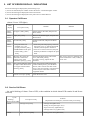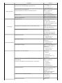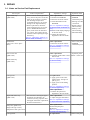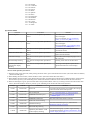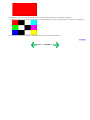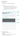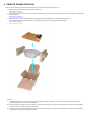
1
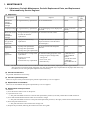
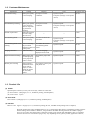
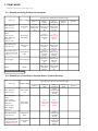
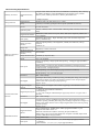
SELPHY DS810
SERVICE
MANUAL
Canon
Copyright 2005, Canon U.S.A. This technical publication is the proprietary and confidential information of Canon U.S.A. which
shall be retained for reference purposes by Authorized Service Facilities of Canon U.S.A. Its unauthorized use is prohibited.
SELPHY DS810
REFERENCE MANUAL
This reference manual describes differences from the base model, SELPHY DS 700.
When referring to the SELPHY DS700 Service Manual, Service Parts Number in it may be different
from SELPHY DS810 model. Please refer to the SELPHY DS810 Parts Catalog (QY8-9077-D0C).
QY8-13AE-000
COPYRIGHT©2005 CANON INC. CANON SELPHY DS810 082005XX 0.00-0
I. MANUAL OUTLINE
This manual consists of the following three parts to provide information necessary to service the SELPHY DS810:
Part 1: Maintenance
Information on maintenance and troubleshooting of the SELPHY DS810
Part 2: Technical Reference
New technology and technical information such as FAQ's (Frequently Asked Questions) of the SELPHY DS810
Part 3: Appendix
Block diagrams and pin layouts of the SELPHY DS810
Reference:
This manual does not provide sufficient information for disassembly and reassembly procedures. Refer to the graphics in the separate
Parts Catalog.
II. TABLE OF CONTENTS
Part 1: MAINTENANCE
1. MAINTENANCE
1-1. Adjustment, Periodic Maintenance, Periodic Replacement Parts, and Replacement Consumables by Service
Engineer
(1)
(2)
(3)
(4)
(5)
Adjustment
Periodic maintenance
Periodic replacement parts
Replacement consumables
Replacement of the print head
1-2. Customer Maintenance
1-3. Product Life
(1) Printer
(2) Print head
(3) Ink tank
1-4. Special Tools
1-5. Serial Number Location
2. LIST OF ERROR DISPLAY / INDICATIONS
2-1. Operator Call Errors
2-2. Service Call Errors
2-3. Warnings
2-4. Troubleshooting by Symptom
3. REPAIR
3-1. Notes on Service Part Replacement
3-2. Special Notes on Repair Servicing
(1) Flexible cable and harness wiring, connection
(2) Notes on disassembly and re-assembly
3-3. Adjustment / Settings
(1)
(2)
(3)
(4)
(5)
(6)
Paper feed motor adjustment
Pump unit adjustment
Grease application
Waste ink counter setting
User mode
Service mode
3-4. Verification Items
(1) Service test print
(2) EEPROM information print
4. PRINTER TRANSPORTATION
Part 2: TECHNICAL REFERENCE
1. NEW TECHNOLOGIES
(1) Main difference from DS700
2. CLEANING MODE AND AMOUNT OF INK PURGED
3. PRINT MODE
3-1. Resolution during Printing via Computer
3-2. Resolution in Card Direct / Camera Direct / Print Beam Printing
4. FAQ (Problems Specific to the SELPHY DS810 and Corrective Actions
Part 3: APPENDIX
1. BLOCK DIAGRAM
2. CONNECTOR LOCATION AND PIN LAYOUT
2-1. Logic Board Ass'y
2-2. Panel Board Ass'y
2-3. Card Board Unit
2-4. Front I/F Unit
2-5. Rear I/F Unit
3. SPECIFICATIONS
Part 1
MAINTENANCE
1. MAINTENANCE
1-1. Adjustment, Periodic Maintenance, Periodic Replacement Parts, and Replacement
Consumables by Service Engineer
(1) Adjustment
Adjustment
Destination
settings
(EEPROM
settings)
Timing
At logic board ass'y replacement
Purpose
Tool
Approx.
time
To set the destination.
None.
1 min.
To set the language to be displayed on
the LCD.
None. (in the user
mode)
1 min.
Waste ink counter - At logic board ass'y replacement To reset the waste ink counter.
resetting
- At waste ink absorber
(EEPROM
replacement
settings)
None.
1 min.
Paper feed motor
ass'y position
adjustment
- At paper feed motor ass'y
replacement
To adjust the belt tension. (Position the
paper feed motor so that the belt is
stretched tight.)
None.
2 min.
Pump unit
adjustment
- At pump unit replacement
To set an accurate ink absorption
function.
None.
2 min.
- At carriage unit / carriage shaft
replacement
- At access cover unit
replacement
To maintain sliding properties of the:
- carriage oil pad / carriage shaft,
carriage rail.
- access cover, and
1 min.
- At feed roller ass'y replacement
- feed roller ass'y.
- GREASE EU-1
- MOLYKOTE
PG641
- FLOIL KG-107A
- GREASE
ELECTRICITY IF20
Language settings At logic board ass'y replacement
- At purge tube replacement
- At pump drive gear replacement
Grease
application
Note: - DO NOT loosen the 2 red screws on both front sides of the main chassis, adjusting the head-to-paper distance.
- The red screws securing the paper feed motor ass'y may be loosened only at replacement of the paper feed motor ass'y.
- For DS810, access cover gear phase adjustment is not necessary.
(2) Periodic maintenance
No periodic maintenance is necessary.
(3) Periodic replacement parts
There are no parts in this printer that require periodic replacement by a service engineer.
(4) Replacement consumables
There are no consumables that require replacement by a service engineer.
(5) Replacement of the print head
Procedures:
1) Press the Power button to turn on the printer.
2) Open the access cover.
=> The print head holder will move to the ink tank replacement position (to the left), and the Power LED remains lit.
3) Press and hold the Resume/Cancel button for 2 seconds or longer.
=> The print head holder will move to the print head replacement position (to the right), and the Power LED remains lit.
4) Raise the print head lock lever.
=> The print head can be removed from the carriage unit.
5) Replace the print head, following the instructions in the user's guide.
1-2. Customer Maintenance
Adjustment
Timing
Purpose
Tool
Approx. time
Print head cleaning
When print quality
is not satisfying.
To improve nozzle
conditions.
- Operation panel
- Computer (settings via the printer
driver)
42 sec.
Print head deep cleaning
When print quality
is not satisfying,
and not improved
by print head
cleaning.
To improve nozzle
conditions.
- Operation panel
- Computer (settings via the printer
driver)
82 sec.
Ink tank replacement
When the ink tank
becomes empty.
(No ink error)
Print head alignment
When print quality
is not satisfying.
Print head alignment value
printing
2 min.
--To ensure accurate dot
placement.
--- Operation panel
- Computer (settings via the printer
driver)
1 min.
When confirming
To confirm the current
the print head
print head alignment
alignment values set values.
in the printer.
- Operation panel
25 sec.
Language selection
When necessary.
To set the language
displayed on the LCD.
- Operation panel
10 sec.
Paper feed roller cleaning
When paper does
not feed properly,
or the paper feed
roller is soiled.
To clean the paper feed
roller.
- Operation panel
2 min.
Bottom plate cleaning
After printing is
performed on the
wrong side of
paper, or rollers
inside the printer
are extremely
soiled.
To clean the bottom plate - Operation panel
and platen ribs.
40 sec.
1-3. Product Life
(1) Printer
Specified print volume (I) or the years of use (II), whichever comes first.
(I) Print volume: 2,000 pages (4" x 6", borderless printing, standard photo)
(II) Years of use: 5 years
(2) Print head
Print volume: 2,000 pages (4" x 6", borderless printing, standard photo)
(3) Ink tank
BCI-16 Color: Approx. 70 pages (4" x 6", borderless printing, PP-101, standard mode printing from a computer)
When do printing the Canon standard pattern on 4" x 6" Photo Paper Plus Glossy in borderless printing, with the
default settings in the Windows XPdriver, using Windows XP Photo Printing Wizard. The number of pages
above is an average value measured in continuous printing, using the ink tank immediately after it is unsealed
until the ink runs out. The number of pages may vary depending on text, photos printed, application software,
print mode, and type of paper used. Ink is consumed at power input and during printing to protect the print head
and keep print quality.
1-4. Special Tools
Name
Tool no.
Application
Remarks
MOLYKOTE
PG641
CK-0562-000
To be applied to the sliding portion of the
access cover arm.
In common with
other models.
FLOIL KG107A
QY9-0057-000
To be applied to the sliding portion of the
carriage guide rail.
In common with
other models.
EU-1
QY9-0037-000
To be applied to the carriage oil pad, and the In common with
sliding portion of the carriage shaft.
other models.
GREASE
CK-8006-000
ELECTRICITY
IF-20
To be applied to the sliding portion of the
feed roller ass'y.
In common with
other models.
1-5. Serial Number Location
On the bottom shield plate.
To the top
<Part 1: MAINTENANCE>
2. LIST OF ERROR DISPLAY / INDICATIONS
Errors and warnings are displayed by the following ways:
1) Errors are indicated by the number of times the Power / Alarm LED lights / blinks.
2) Errors and warnings are displayed on the LCD monitor.
3) Errors and warnings are displayed on the printer driver's Status Monitor.
2-1. Operator Call Errors
(Alarm / Power LED lights)
LED
display
Solution
Error [Error code]
Alarm
LED lit
No paper. (ASF) [1000]
Set the paper in the ASF, and press the
Reset button.
Alarm
LED lit
Paper jam. [1300]
Remove the jammed paper, and press the
Reset button.
Alarm
LED lit
No ink tank. [1662]
Install an ink tank, and press the Reset
button.
Alarm
LED lit
- The print head is not
installed, or it is not
properly installed. [1401]
- EEPROM data of the print
head is faulty. [1403 /
1405].
- Install the print head properly, and close
the access cover, or, with the print head
installed, turn the printer off and on.
- If the error is still not resolved, the print
head may be defective. Replace the print
head.
Alarm
LED lit
Warning: The waste ink
absorber is almost full
(approx. 95% of the
maximum capacity). [1700]
Pressing the Reset button will exit the
error, and enable printing.
In repair servicing, replace the ink
absorbers.
Alarm
LED lit
The connected digital camera
or digital video camera does
not support Camera Direct
Printing. [2001]
After removing the cable between the
camera and the printer, press the Reset
button, and re-connect the cable. If the
error is still not resolved, a non-supported
camera may be connected. Connect a
supported camera.
Access cover open. [1200]
Close the access cover.
Remarks
The service call error, indicating the
waste ink absorber is full, is likely to
occur soon.
2-2. Service Call Errors
(by cyclic blinking of Alarm / Power LED, or the condition in which Alarm LED remains lit and Power
LED off)
Cyclic
blinking :
Alarm / Power LED
2 times
Error [Error code]
Carriage error [5100]
Solution
(Replacement of listed parts, which are likely to be faulty)
- Carriage unit (QM2-3257)
- Timing slit strip film (QC1-5153)
- Logic board ass'y (QM2-2880)*1
- Carriage motor ass'y (QM2-1744)
3 times
Paper feed error [6000]
- Timing sensor unit (QM2-2894)
- Timing slit disk ass'y (QL2-0843)
- Paper feed motor ass'y (QM2-1746)
- Feed roller ass'y (QM2-1970)
- Platen (QC1-5176/5177)
4 times
Purge unit error [5C00]
- Logic board ass'y (QM2-2880)*1
- Purge unit (QM2-1975)
- Logic board ass'y (QM2-2880)*1
5 times
ASF cam sensor error [5700]
- Sheet feed unit (QM2-3264)
6 times
Internal temperature error [5400]
- Logic board ass'y (QM2-2880)*1
7 times
Waste ink absorber full [5B00]
- Ink absorber (QC1-5195 / 5196 / QY5-0162)
- After replacement of the ink absorber, reset the EEPROM
(waste ink amount value) on the logic board ass'y.
8 times
Print head temperature rise error
[5200]
- Print head (QY6-0056)
9 times
EEPROM error [6800]
- Logic board ass'y (QM2-2880)*1
Continuous
alternate blinking
ROM error
- Logic board ass'y (QM2-2880)*1
Alarm LED lit /
Power LED off
RAM error
- Logic board ass'y (QM2-2880)*1
- Logic board ass'y (QM2-2880)*1
*1: Before replacement of the logic board ass'y, check the waste ink amount (by service test print or EEPROM information
print). If the waste ink amount is 7% or more, also replace the ink absorbers (QC1-5195 / 5196 / QY5-0162 ) when
replacing the logic board ass'y.
[See Section 3-3. Adjustment / Settings, (6) Service mode, for details.]
2-3. Warnings
Printer (displayed via the Status Monitor or on the LCD monitor, no LED indication):
Displayed warning
Remarks
Ink low warning 1 (approx. half level)
The warning is displayed only when printer driver's Low Ink
Warning Setting is enabled.
Ink low warning 2 (low remaining ink, display of "!" in the
warning)
The warning is displayed only when printer driver's Low Ink
Warning Setting is enabled.
Ink low warning 3 (ink level unknown, display of "?" in the
warning)
The warning is displayed only when printer driver's Low Ink
Warning Setting is enabled.
Print head temperature rise
If the print head temperature is high when the access cover is
opened, the warning is displayed.*1
When the print head temperature falls below the specified
temperature, the warning is released.
Protection against excess rise of the print head temperature
If the print head temperature exceeds the specified limit, a
Wait is inserted during printing,
When the print head temperature falls below the specified
temperature, the warning is released.
*1: If the warning is displayed, the carriage does not move to the ink tank replacement position when the access cover is
opened.
2-4. Troubleshooting by Symptom
Symptom
The power does not turn on.
The power turns off immediately after power-on.
Solution
Replace the
- AC adapter, or
- logic board ass'y*1.
Faulty operation
The print head is not recognized.
The print head does not return to the home position.
Remove and re-install the print
head, or replace the
- print head, or
- logic board ass'y*1.
LCD display
Strange noise.
Remove foreign material, or
attach a removed part if any.
Printing stops mid-way.
Replace the logic board ass'y*1.
Display flickers.
Check images within the
memory card.
Or replace the LCD viewer
unit, the card board unit, or the
logic board ass'y.*1
No display (the whole black screen or whole white screen)
Replace the LCD viewer unit,
or the logic board ass'y*1.
Streaks are present in the LCD.
Check images within the
memory card.
Or replace the LCD viewer
unit or the card board unit.
Multiple sheets feed.
Replace the
- sheet feed unit, or
- output tray unit.
Paper does not feed.
Remove foreign material, or
replace the
- sheet feed unit, or
- output tray unit.
Paper feeds at an angle.
Remove foreign material, or
adjust the paper guide, or
replace the
- sheet feed unit, or
- output tray unit.
No printing, or no color ejected.
Replace the
- ink tank,
Paper feed problems
- print head*2,
- logic board ass'y*1, or
- purge unit.
Printing is faint, or white lines appear on printouts even after print
head cleaning.
Line(s) not included in the print data appears on printouts.
Remove and re-install the print
head, or replace the
- ink tank,
- print head*2,
- purge unit, or
- logic board ass'y*1.
Paper gets smeared.
Feed several sheets of paper,
perform bottom plate
cleaning*3, or
clean the paper path with
cotton swab or cloth.
A part of a line is missing on printouts.
Replace the
- ink tank, or
- print head*2.
Unsatisfactory print
Color hue is incorrect.
Replace the
- ink tank, or
quality
- print head*2, or
perform print head alignment.
Printing is incorrect.
Replace the logic board ass'y*1.
Non-ejection of ink.
Replace the
- ink tank, or
- print head*2.
Graphic or text is enlarged on printouts.
When enlarged in the carriage
movement direction, clean
grease or oil off the timing slit
strip film, or replace the
- timing slit strip film,
- carriage unit, or
- logic board ass'y*1.
When enlarged in the paper
feed direction, clean grease or
oil off the timing slit disk ass'y,
or replace the
- timing slit disk ass'y,
- timing sensor unit, or
- logic board ass'y*1.
*1: Before replacement of the logic board ass'y, check the waste ink amount (by service test print or EEPROM information
print). If the waste ink amount is 7% or more, also replace the ink absorbers (QC1-5195 / 5196 / QY5-0162 ) when
replacing the logic board ass'y.
[See Section 3-3. Adjustment / Settings, (6) Service mode, for details.]
*2: Replace the print head only after the print head deep cleaning is performed 2 times, and when the problem persists.
*3: To perform bottom plate cleaning, with the printer power turned on, use of operation panel buttons with the LCD monitor
(Menu -> Tool Box -> Maintenance). For details, see Section 3-3. Adjustment / Settings, (5) User mode.
To the top
<Part 1: 2. LIST OF ERROR DISPLAY / INDICATION>
3. REPAIR
3-1. Notes on Service Part Replacement
Notes on replacement*1
Adjustment / settings
Operation check
- Before removal of the logic board
ass'y, remove the power cord, and
allow for to sit approx. 1 minute
(for discharge of capacitor's
accumulated charges), to prevent
damage to the logic board ass'y.
- Before replacement, check the
waste ink amount (by service test
print or EEPROM information
print). If the waste ink amount is
7% or more, also replace the ink
absorbers when replacing the logic
board ass'y.
[See 3-3. Adjustment / Settings, (6)
Service mode, for details.]
After replacement:
1. Initialize the EEPROM.
2. Reset the waste ink counter.
3. Set the destination in the
EEPROM.
[See 3-3. Adjustment / Settings,
(6) Service mode, for details of 1
to 3]
4. Set the LCD display language
in the user mode.
5. Perform the print head
alignment in the user mode.
- Service test print
- EEPROM
information print
- Printing via USB
connection
- Digital Camera
Direct Printing
- Memory Card
Direct Printing
- Infrared Printing
Ink absorber
(QC1-5195 / 5196 / QY50162)
After replacement:
1. Reset the waste ink counter.
[See 3-3. Adjustment / Settings,
(6) Service mode.]
- Service test print
- EEPROM
information print
LCD viewer unit
- Operation panel
After replacement:
1. Operation panel button / LCD button / viewer test
monitor test
[See 3-3. Adjustment / Settings,
(6) Service mode.]
Service part
Logic board ass'y
(QM2-2880)
(QM2-3266)
Panel board ass'y
(QM2-3267)
Carriage unit
(QM2-3257)
Paper feed motor ass'y
(QM2-1746)
At replacement:
1. Apply grease to the entire
surface of the carriage oil
pads (2 pcs.).
2. Apply grease to the sliding
portions.
[See 3-3. Adjustment / Settings,
(3) Grease application.]
After replacement:
1. Perform the print head
alignment in the user mode.
- The red screws securing the paper
feed motor are allowed to be
loosened. (For any purposes other
than paper feed motor replacement,
DO NOT loosen them.)
- Service test print
- Service test print
After replacement:
1. Adjust the paper feed motor.
[See 3-3. Adjustment / Settings,
(1) Paper feed motor adjustment.]
- Service test print
Purge Tube (QC1-5555),
Pump Drive Gear (QC1-5253)
After replacement:
Perform the pump unit
adjustment.
[See 3-3. Adjustment / Settings,
(2) Pump unit adjustment.]
Carriage shaft
At replacement:
- Service test print
Pump unit (QM2-1979),
(QC1-5150)
Timing slit strip film
(QC1-5153)
Timing slit disk ass'y
(QL2-0843)
Print head
(QY6-0056)
1. Apply grease to the sliding
portions.
[See 3-3. Adjustment / Settings,
(3) Grease application.]
- Upon contact with the film, wipe the After replacement:
film with ethanol.
1. Perform the print head
- Confirm no grease is on the film.
alignment in the user mode.
(Wipe off any grease thoroughly
with ethanol.)
- Service test print
- Do not bend the film.
After replacement:
1. Perform the print head
alignment in the user mode.
- Service test print
*1: General notes:
- Make sure that the flexible cables and wires in the harness are in the proper position and connected correctly.
[See 3-2. Special Notes on Repair Servicing, (1) Flexible cable and harness wiring, connection, for details.]
- Do not drop the ferrite core, as it may damage the core.
- Protect electrical parts from damage due to static electricity.
- Before removing a unit, after removing the power cord, allow the printer to sit for approx. 1 minute (for capacitor
discharging to protect the logic board ass'y from damages).
- Do not touch the timing slit strip film and timing slit disk ass'y. No grease or abrasion is allowed.
- Protect the units from becoming soiled with ink.
- Protect the housing from scratches.
- Exercise caution with the red screws, as follows:
i. The red screws of the paper feed motor may be loosened only at replacement of the paper feed motor ass'y (DO
NOT loosen them in other cases).
ii. DO NOT loosen the red screws on both front sides of the main chassis, securing the carriage guide rail positioning
(they are not adjustable in servicing).
To the top
<Part 1: 3. REPAIR 1>
3-2. Special Notes on Repair Servicing
(1) Flexible cable and harness wiring, connection
Exercise care when handling the flexible cables and harness wiring. Improper wiring or connection may cause a short-circuit, and may
lead to ignition or emission of smoke.
(I) Panel board ass'y and front I/F unit wiring
(II) Logic board ass'y wiring
J301, J302, J303: Carriage Flat Flexible Cable (Carriage Unit) connectors
J401: DC Harness ass'y connector
J402: PE sensor and PG sensor connector
J403: Connected to the PF/ASF sensor inside the sheet feed unit
J404: Battery holder ass'y harness connector
J501: Card harness ass'y connector
J505: Panel cable unit connector
J601: Connected to the AP motor harness inside the sheet feed unit
J602: Carriage motor ass'y connector
J603:
J701:
J702:
J703:
Paper feed motor ass'y connector
USB harness ass'y connector
DSC harness ass'y connector
IR cable connector
(III) Printer unit wiring
<Enlarged View>
<Wiring of Logic Board Ass'y assembled in Bottom Case Ass'y>
(IV) Paper feed motor ass'y wiring
(V) Carriage motor ass'y and PE sensor harness wiring
(VI) Front I/F unit wiring
(VII) Rear I/F unit wiring
(VII) Panel cable unit wiring
<Wiring in Bottom Case Ass'y>
<Wiring in Access Panel Ass'y / Main Cover Ass'y>
To the top
<Part 1: 3. REPAIR (2)-1>
(2) Notes on disassembly and re-assembly
For DS810, only removal methods of external parts which are different from DS700 are described.
Since external parts of DS810 contains the mirror / coated parts, make sure not to scratch or smear them.
For notes on disassembly and re-assembly of parts other than the parts shown below, refer to DS700 Service Manual.
z
Access Sub Panel removal
From the rear side of the printer, remove the access sub panel by lifting it frontward using fingers.
(There are seven claws. Make sure not to break (not even whiten) them.)
z
Output Tray Unit removal
1) Release the left hook, pulling out the left side of the paper tray. (Release the left side first, then the right side.)
2) Release the hook, pushing the both sides of the paper output tray.
* After lifting the printer's left side, release the hook (the left hook first) with the paper output tray declined.
z
Front Cover removal
1) Remove the screw from the bottom face.
2) Release the two claws of the front cover from the lower right / left part of the main cover main cover. (Release the left claw first
and the right claw next.)
3) Release the two claws of the front cover from the lower right / left part of the bottom case.
(After lifting the printer's left side, release the left claw first with the paper output tray declined.)
z
Side Cover R removal
From the printer's bottom face, lift and remove the side cover R, using a flathead screwdriver or the like.
z
Side Cover L removal
Open the access panel cover and remove the side cover L by pushing its protruding portion from the printer's inside.
z
Access Panel / Access Panel Shield Plate removal
1) Remove the two screws from the upper portion of the access panel with the access panel cover closed.
2) With the access panel cover open, remove the two screws from the shield plate which is located behind the access panel.
3) Removing the hanging springs, detatch the access panel shield plate.
4) Remove the panel cable unit from the connector first, and from the access panel next.
5) Remove the the right / left hinges of the access cover from the main cover.
z
Main cover unit removal
1) Remove 2 screws from the left side and 2 screws from the right side.
<Right Side>
2) Release the two claws on the back side.
<Left Side>
3) Release the two claws located at the right / left side of the front side.
To the top
<Part 1: 3. REPAIR, (2)-2>
3-3. Adjustment / Settings
As the following adjustments / settings (excluding user mode and service mode) for DS810 are the same as those for DS700,
see DS700 Service Manual for details as a reference.
For DS810, access cover gear phase adjustment and grease application on the access cover are not necessary.
(1) Paper feed motor adjustment
(2) Pump unit adjustment
(3) Grease application
(4) Waste ink counter setting
(5) User mode
Function
Procedures
Remarks
Nozzle check pattern printing
Use of operation panel buttons with Available through the printer driver
utility functions as well
the LCD monitor
(Menu -> Tool box ->
Maintenance)
Print head cleaning
Use of operation panel buttons with Available through the printer driver
utility functions as well
the LCD monitor
(Menu -> Tool box ->
Maintenance)
Print head deep cleaning
Use of operation panel buttons with Available through the printer driver
utility functions as well
the LCD monitor
(Menu -> Tool box ->
Maintenance)
Print head alignment
Use of operation panel buttons with Available through the printer driver
utility functions as well
the LCD monitor
(Menu -> Tool box ->
Maintenance)
Print head alignment values
printing
Use of operation panel buttons with
the LCD monitor
(Menu -> Tool box ->
Maintenance)
Language selection*1
Use of operation panel buttons with
the LCD monitor
(Menu -> Tool box -> each setting)
Paper feed roller cleaning
Use of operation panel buttons with Set several sheets of 4" x 6" sized paper
with the non-print side facing up.
the LCD monitor
(Menu -> Tool box ->
Maintenance)
Bottom plate cleaning
Use of operation panel buttons with Set Canon genuine paper MP-101 4" x
6", GP-401 4" x 6", or GP-501 4" x 6"
the LCD monitor
in the auto sheet feeder.
(Menu -> Tool box ->
Maintenance)
LCD viewer contrast adjustment
Use of operation panel buttons with
the LCD monitor
(Menu -> Tool box -> each setting > other setting)
Print head friction prevention
Paper thickness lever: right side ->
left side
Print head replacement
Press and hold the Stop / Reset
button for more than two seconds at
the ink tank replacement position ->
moves to the print head replacement
position
*1: Selectable from among the following 15 languages in the user mode (through operation panel buttons with the LCD monitor):
LG = 01 Japanese
LG = 02 English
LG = 03 S. Chinese
LG = 04 German
LG = 05 French
LG = 06 Italian
LG = 07 Spanish
LG = 08 Dutch
LG = 09 Portuguese
LG = 0B Swedish
LG = 0E Russian
LG = 0F Czecho
LG = 10 Hungarian
LG = 11 Polish
(6) Service mode
Function
Procedures
Remarks
Service test print
See "Service mode operation procedures"
below.
Set a sheet of 4" x 6"(101.6 mm x 152.4
mm)-sized paper.
For a print sample, see 3-4. Verification
Items, (1) Service test print.
EEPROM information print
See "Service mode operation procedures"
below.
Set a sheet of 4" x 6"(101.6 mm x 152.4
mm)-sized paper.
For a print sample, 3-4. Verification Items,
(2) EEPROM information print.
EEPROM initialization
See "Service mode operation procedures"
below.
The following item is NOT initialized:
- Waste ink counter
Waste ink counter reset
See "Service mode operation procedures"
below.
If the waste ink amount is 7% or more,
replace the ink absorbers.
Destination settings
See "Service mode operation procedures"
below.
The LCD monitor display language is set in
the user mode.
Print head deep cleaning
See "Service mode operation procedures"
below.
Cleaning of all colors at the same time.
Operation panel buttons /
LCD monitor display
checking
See "Service mode operation procedures"
below.
Checking on the operation panel buttons
operation and the LCD viewer display
<Service mode operation procedures>
1) With the printer power turned off, while pressing the Reset button, press and hold the Power button. (DO NOT release the buttons.)
(The Power LED lights.)
2) While holding the Power button, release the Reset button. (DO NOT release the Power button.)
3) While holding the Power button, press the Reset button 2 times, and then release both the Power and Reset buttons. (Each time the
Reset button is pressed, cycles of blinking of the Alarm LED and Power LED start and a mode becomes the menu selection.)
4) When the LED lights in green, press the Reset button the specified number of time (s) according to the function listed in the table
below. (Each time the Reset button is pressed, cycles of blinking of the Alarm LED and Power LED start.)
Time(s)
LED lit
Function
Remarks
0 times
Power LED
Power off
Even when the print head is not installed, the carriage
returns and locks in the home position.
1 time
Alarm LED
Service test print
See 3-4. Verification Items, (1) Service test print.
2 times
Power LED
EEPROM information print
See 3-4. Verification Items, (2) EEPROM
information print.
3 times
Alarm LED
EEPROM initialization
The waste ink counter value is not reset.
4 times
Power LED
Waste ink counter resetting
5 times
Alarm LED
Destination settings
6 times
Power LED
Print head deep cleaning
11 times
Alarm LED
Operation panel buttons / LCD
monitor display checking
Proceed to the following step 5), and follow the
Destination settings procedures.
After the following step 5), follow signal switching
procedures through the operation panel buttons / LCD
monitor display checking.
7, 9 times:
7 to 10 times Alarm
More than 12 LED
times
8, 10, 12 times:
Power LED
Returns to the menu selection
5) After the function (menu) is selected, press the Power button. The Power LED lights, and the selected function is performed. (When
the operation completes, the printer returns to the menu selection mode automatically.)
Note: To exit the service mode, press the Power button.
<Destination settings procedures>
In the destination settings mode, press the Reset button the specified number of time(s) according to the destination listed in the table
below, and press the Power button.
After setting the destination, operate EEPROM initialization indicated in Service mode operation procedures above.
Time(s)
LED
Destination
Paper setting
0 times
Power LED
No destination change
-
1 time
Alarm LED
JPN
L
2 times
Power LED
KRN
4x6
3 times
Alarm LED
US
4x6
4 times
Power LED
EUR
4x6
5 times
Alarm LED
AU
4x6
6 times
Power LED
ASA
4x6
7 times
Alarm LED
CN
4x6
8 times
Power LED
TW
4x6
9 times or more
Power LED
Returns to the destination settings mode
-
Note: After setting the destination, confirm the settings in the service test print or EEPROM information print.
[See 3-4. Verification Items, (1) Service test print, or (2) EEPROM information print.]
<Operation panel buttons / LCD monitor display checking>
After a mode is shifted to the operation panel button / LCD monitor display, check the panel buttons operation and the LCD monitor
display by implementing
the following procedures.
1) When the Stop / Reset button was pressed one time, the entire LCD monitor screen is changed to blue.
(If an error occurs, the Alarm LED lights.)
2) When each button (excluding Power, Stop / Reset, and OK button) on the operation panel is pressed, a part of screen is changed to
red accordingly.
For the color change (blue -> red) in the screen by each button operation, see the diagram below.
3) When all buttons excluding the Power, Stop / Reset, and OK button are pressed, the entire screen is changed to red.
4) When the access cover is opened with the entire screen being red, the following color pattern is displayed.
When the access cover is opened without the entire screen becoming red in step 3), the following color pattern is not displayed.
5) When the Power button is pressed, a mode returns to the service mode menu selection.
To the top
<Part 1: 3. REPAIR 3>
3-4. Verification Items
(1) Service test print
After repair, perform service test print, and confirm the items below.
Note: Use a sheet of 4" x 6" (101.6 mm x 152.4 mm)-sized paper.
<Print check items>
On the service test print (sample below), confirm the following items:
- Check 1, top of form accuracy: The line shall not extend off the paper.
- Check 2, EEPROM information: Destination settings, waste ink amount, etc.
- Check 3, nozzle check pattern: Ink shall be ejected from all nozzles.
- Check 4, halftone: There shall be no remarkable streaks or unevenness.
- Check 5, vertical straight lines: The line shall not be broken.
<Service test print sample>
(2) EEPROM information print
<How to read the EEPROM information print>
Print sample:
1:01 2:DS810 3:V1.01 4:IF(USB=1) 5:D=010.7 6:ST=2005/06/23-08:57
7:ER(ER0=1000 ER1=0000) 8: LPT=2005/07/06-15:11
9: PC(M=0041 R=001 T=001 D=002 C=003)
10: CLT(2005/07/06-15:00)
11:CH=00001 12:CT=00003 13:IS(C=0 M=0 Y=0) 14:IC(C=00016 M=00016 Y=00016)
15:P_ON(S=00006 H=00005) 16:P_OFF(S=00005) 17:M_REG=0
18:UR(A(Coe)=-01 B(SCoe)=+01 C(CLbi)=000 D(SCLbi)=+01)
19:LG=01 Japanese 20:WP=0193 21:CDIN(LG=000 PB=000 OPB=000)
22:BTIN=0 23:MSD(020)
24:PAGE(All=00133 PP=00000 HR+MP=00021 PR+SP+SG=00108 GP=00004
PC=00000) 25:CDPAGE(All=00000) 26:EDGE=00000 27:L=00120
28:DCR=001 29:DCRC=00000 30:Head Temp=26.5
31:Env Temp=26.5 32:FF(80 00 05) 33:OPP=00000 34:BTPAGE=00025 35:PrnB=00000
36:Seal=00000 37:CardPaper=00039 38:CardIns(0030) 39:CardPrn(0077)
40:CDD-PR(L=005 PC=005) 41:CDD-SP(L=010 PC=017)
42:CDD-MP(L=008 PC=000) 43:DCD-PP(L=001 PC=000)
44:DCD-FPP(L=002 PC=000) 45:DCD-MPP(L=003 PC=000)
HDEEPROM
46:V0001 47: SN=0001-0D7B
48:LN(00000 00000 00000 00003 00013 00017 00015) 49:ID=05
50:IL=(C=000 M=000 Y=000)
Printed items:
1:
2:
3:
4:
Destination setting
Model name (same for the all destinations)
ROM version
USB I/F connection
Once the printer is connected via USB, "IF(USB=1)" is printed.
5: Waste ink amount (%) (D: Drain)
6: Installation date and time (ST: Set Time)
7: Operator call / service call error record (ER0 = latest error, ER1 = previous error)
8: Last printing time (last time before an error) (LPT: Last Print Time)
9: Purging count (PC: Purge Count) (M = manual cleaning, R = (Refreshing) deep cleaning, T = timer cleaning, D = cleaning by dot
count, C = cleaning at ink tank / print head )
10: Last cleaning time (CLT: Cleaning Time)
11: Print head replacement count (CH: Change Head)
12: Ink tank replacement count (CT: Change Tank)
13: Ink status (IS: Ink Status)
The number 0, 1, 2, or 3, corresponding to the Low Ink Warning level is printed.
14: Total ink consumption (IC: Ink Consumption) in mg
15: Power-on count (S = soft-power-on, H = hard-power-on)
16: Power-off count (S = soft-power-off)
17: Manual print head alignment by user (1 for performed, 0 for not performed)
18: User print head alignment value (UR: User Registration)
19: Language setting (LG: Language)
The specified language is printed.
LG=01 Japanese
LG=02 English
LG=03 S.Chinese
LG=04 German
LG=05 French
LG=06 Italian
LG=07 Spanish
LG=08 Dutch
LG=09 Portuguese
LG=0AB Swedish
LG=0E Russian
LG=0F Czecho
LG=10 Hungarian
LG=11 Polish
20: Wiping count (WP = Wiping)
21: Camera Direct Print-supported device connection record (CDIN: Camera Direct Insert)
LG = Legacy (Canon Bubble Jet Direct), PB = Canon PictBridge, OPB = Other PictBridge
22: Bluetooth-supported device connection record (BTIN = Bluetooth Insert)
23: Longest period of non-printing (MSD: Maximum Stop Date)
24: Number of pages fed (total, plain paper, High Resolution Paper & Matte Photo Paper, Photo Paper Pro & Photo Paper Plus Glossy
& Photo Paper Plus Semi-gloss, Glossy Photo Paper, postcard)
25: Camera Direct print pages in total (CDPAGE: Camera Direct PAGE)
26: Borderless print pages
27: L & 4x6 print pages
28: Number of times dot count is reset (DCR: Dot Count Reset)
The number of times ink counter reset is performed (OK is clicked) at Ink Low Warning 2 or 3.
29: Number of times dot count reset is cancelled (DCRC: Dot Count Reset Cancel)
The number of times ink counter reset is cancelled at Ink Low Warning 2 or 3.
30: Print head temperature
31: Inside temperature
32: Line inspection information (FF: Factory Function) (Not used in field service)
33: Other Photo Paper pages fed (Not used in field service, as the DS810 does not support Other Photo Paper.)
34: Bluetooth printing pages fed (BrnB=Print Beam) (not counted for Bluetooth printing only)
35: Print Beam printing pages fed (PrnB: Print Beam) (by IRDA & Bluetooth printing)
36: Photo Sticker pages fed
37: Name card- / Credit Card-sized paper pages fed
38: Number of times a memory card is used
39: Memory Card Direct print pages in total
40: Memory Card Direct print pages: Photo Paper Pro (L/4x6, Japanese postcard)
41: Memory Card Direct print pages: Photo Paper Plus Glossy (L/4x6, Japanese postcard)
42: Memory Card Direct print pages: Matte Photo Paper (L/4x6, Japanese postcard)
43: Camera Direct print pages: Photo Paper (L/4x6, Japanese postcard)
44: Camera Direct print pages: Fast Photo Paper (L/4x6, Japanese postcard)
45: Camera Direct print pages: Matte Photo Paper (L/4x6, Japanese postcard)
HDEEPROM
46: Version
47: Serial number
48: Lot number
49: Print head ID
50: Ink ejection level (C/M/Y)
To the top
<Part 1: 3. REPAIR 4>
4. PRINTER TRANSPORTATION
This section describes the procedures for transporting the printer for returning after repair, etc.
1) Keep the print head and ink tank installed in the carriage.
[See Caution 1 below.]
2) Turn off the printer to securely lock the carriage in the home position. (When the printer is turned off, the carriage is automatically
locked in place.)
[See Caution 2 below.]
3) Attach the left / right side packing and accessory packing to protect the printer, and set in the packing box.
Note: If the packing used when the box was opened is not available, use packing of the same grade.
[See Caution 3 below.]
Caution:
(1) If the print head is removed from the printer and left alone by itself, ink is likely to dry. For this reason, keep the print head
installed in the printer even during transportation.
(2) Securely lock the carriage in the home position, to prevent the carriage from moving and applying stress to the carriage flexible
cable or causing ink leakage during transportation.
(3) Attach the accessory and side packing to the printer when transporting it, to prevent the print head face surface from contacting
the purge base, and from scratching the nozzles.
Memo:
If the print head must be removed from the printer and transported alone, perform the following:
(1) Install the ink tank (to prevent the nozzles from drying).
(2) Attach the protective cap (used when the packing was opened) to the print head (to protect the print head face from damage due
to shocks).
To the top
<Part 1: 4. PRINTER TRANSPORTATION>
Part 2
TECHNICAL REFERENCE
1. NEW TECHNOLOGIES
< Main difference from DS700 >
DS810
DS700
(1) AC adapter
Multi-supported
AC100 - 240V 50/60Hz
AC100 - 120V 50/60Hz
AC220 - 240V 50/60Hz
(2) Memory card
images display
The mounted 2.5 color LCD monitor
(TV screen output: not supported)
TV screen
(3) Throughput
Camera Direct printing (standard photo
image)
PP-101/4x6/borderless printing
(Default): Approx. 63 sec.
Camera Direct printing (standard photo
image)
PP-101/4x6/borderless printing
(Default): Approx. 85 sec.
(4) Print mode
Card Direct printing (Photo Plus Glossy): Card Direct printing (Photo Plus Glossy):
High, Standard
Standard only
(5) Supported paper
size (max.)
Printing from a computer: 4 x 8
Card / Camera Direct printing: 4 x 6
Printing from a computer: 4 x 6
Card / Camera Direct printing: 4 x 6
Supported by using the optional BU-20.
(6) Bluetooth
Supported model:
A mobile phone / PDA incorporating
Bluetooth, compliant with OPP (Object
Push Profile) or BIP (Basic Imaging
Profile)
Printable data:
Image (JPEG only)
Not supported
Supported paper type:
As with Infrared printing
(7) Other
Additional function:
- Correction of images (a mobile phone)
- Red eye reduction
---
To the top
<Part 2: 1. NEW TECHNOLOGIES>
2. CLEANING MODE AND AMOUNT OF INK PURGED
To prevent printing problems due to bubbles, dust, or ink clogging, print head cleaning is performed before the start of printing,
except in the following cases:
- Cleaning on arrival: Performed when the access cover is closed.
- Cleaning by dot count: Performed after ejection of paper.
- Manual cleaning / deep cleaning: Performed manually.
<Cleaning mode list>
Color: C / M / Y
Condition
Details
Est. amount of ink used (g)
Est. required
time (sec.)
On arrival of the
printer
First cleaning after shipped from the
plant.
0.48
82
Dot count cleaning
When the specified number of dots are
printed since the previous cleaning.
0.16
42
Timer cleaning - 1
If 504 to 720 hours have elapsed since 0.16
the previous cleaning till the start of the
next printing.
42
Timer cleaning - 2
If more than 720 hours have elapsed
since the previous cleaning till the start
of the next printing.
0.32
62
At print head
replacement
When the print head is removed and
installed.
0.48
82
0.32
62
0.16
42
0.48
82
0.32
62
At ink tank
replacement
Head cleaning
- Via the printer button
- Via the printer driver
- Via the operation panel buttons on the
LCD monitor
Deep cleaning
- Via the printer driver
- Via the operation panel buttons on the
LCD monitor
If the print head has not
been capped for more
than 1 hour before
power-on
To the top
<Part 2: 2. CLEANING MODE>
3. PRINT MODE
* Changes from DS700 are described in red.
3-1. Resolution during Printing via Computer
Print direction, ink used, and resolution (dpi)
Paper type
Paper setting
Quality 1
Photo Paper Pro
(PR-101 4x6)
Photo Paper
Pro
Photo Paper Plus
Glossy
(PP-101 4x6)
Photo Paper Plus
Semi-gloss
(SG-101 4x6)
Photo Paper
Plus Glossy
Matte Photo Paper
(MP-101 4x6)
Matte Photo
Paper
Glossy Photo Paper
(GP-401 4x6/Credit
Card/GP-501 4x6)
Glossy Photo
Paper
Ink Jet Hagaki
Ink Jet Hagaki
Hagaki
16 passbidirectional
4800x1200
2pl
Hagaki
Quality 2
(High)
12 passbidirectional
1200x600
2pl
Quality 3
(Standard)
6 passbidirectional
1200x600
2pl/5pl
12 passbidirectional
1200x600
2pl
4 passbidirectional
1200x600
2pl/5pl
12 passbidirectional
1200x600
2pl
12 passbidirectional
1200x600
2pl/5pl
12 passbidirectional
1200x600
2pl
6 passbidirectional
1200x600
2pl/5pl
6 passbidirectional
1200x600
2pl/5pl
6 passbidirectional
1200x600
2pl/5pl
6 passbidirectional
1200x600
2pl/5pl
4 passbidirectional
1200x600
5pl
Quality 4
(Draft)
Quality 5
-
Default setting on the driver UI
3-2. Resolution in Card Direct / Camera Direct / Infrared Printing
Print direction, ink used, and resolution (dpi)
Paper type
Paper setting
Quality 1
Photo Paper Pro
(PR-101 4x6)
Photo Paper Plus
Glossy
(PP-101 4x6)
Photo Paper Plus
Semi-gloss
(SG-101 4x6)
Photo Stickers
Quality 2
(High)
Quality 3
(Standard)
6 passbidirectional
1200x600
2pl/5pl
8 passbidirectional
1200x600
2pl/5pl *2
4 passbidirectional
1200x600
2pl/5pl
Photo Paper
Pro
Photo Paper
Plus Glossy
(PS-101)*1
Matte Photo Paper
(MP-101 4x6)
Matte Photo
Paper
Glossy Photo Paper
(GP-401 4x6/Credit
Card/GP-501 4x6)
Glossy Photo
Paper
6 passbidirectional
1200x600
2pl/5pl
6 passbidirectional
1200x600
2pl/5pl
Quality 4
(Draft)
Quality 5
Notes on PictBridge supported digital camera:
1. Paper size and paper type settings in the camera
When Default is selected for the paper size and paper type in the camera, printing is performed according to the printer's paper size and
paper type settings.
(It is possible to select the same print mode as Card Direct Printing.)
2. When paper type (other than default) is set in the camera
Printing is performed in the following print mode:
- Fast Photo: Photo Paper Pro / Standard (Quality 3)
- Photo: Photo Paper Plus Glossy / Standard (Quality 3)
Notes on BubleJetDirect supported digital camera:
- Card#1 (4x6): Photo Paper Pro / Standard (Quality 3)
- Card#2 (4x6): Photo Paper Plus Glossy / Standard (Quality 3)
*1: In Print Studio, select Sticker print.
*2: Print Beam not supported.
To the top
<Part 2: 3. PRINT MODE>
4. FAQ (Problems Specific to the SELPHY DS810 and Corrective Actions)
No. *
1
2
3
4
B
B
B
B
Function
Condition
Soiling on the
back side of
paper (lines or
streaks parallel
to the paper
feed direction)
After continuous
borderless
printing of small
sized paper (such
as Credit Card),
when a larger
sized paper (such
as 4x6) is printed
In borderless
1. Perform Bottom plate cleaning (In - Paper gets
printing, printing
the LCD monitor, select Tool box
smeared.
is performed to the
-> Maintenance) up to 3 times. For - The back
size slightly larger
details, please refer to the user's
side of
than the paper size,
guide.
paper gets
and ink off the
smeared.
2. If soiling on the paper still remains
paper is absorbed
even after Bottom plate cleaning,
by the platen's ink
wipe protruding portion of the
absorber.
platen and their surroundings with
Absorbed ink may
a cotton swab. For details, please
attach to the platen
refer to the user's guide.
rib(s) after several
dozen sheets are
printed, causing
soiling at the
leading edge of
paper or on the
back side of paper.
Skewed paper
feeding with
Credit Cardsized paper
- In the high
temperature and
high humidity
environment
- In the low
temperature and
low humidity
environment
- With the
maximum 20
sheets loaded
As the paper may
be caught by the
ASF base corner,
and creased and
rotated.
With Credit
Card-sized
paper, the
leading edge of
paper contacts
the print head.
In the high
temperature and
high humidity
environment
Due to paper
- Set paper's curl straight.
swelling in the
- Increase the head-to-paper distance
high temperature
by setting the paper thickness lever
and high humidity
to the left.
environment.
Printing is
scratched.
The memory
card cannot be
removed from
the card slot.
When using the
memory card
(miniSD /
Memory Stick
Duo / xD-Picture
Card) which
needs the adapter.
A user inserts the
memory card
without using the
adapter.
- The memory
card
cannot be
removed.
- Data stored
in the
memory
card cannot
be read.
(Accessing
to the
memory
card is not
possible.)
Print
results
Paper
feeding
Print
results
Cause
Corrective Action
Possible call
or complaint
Phenomenon
Reduce the number of sheets loaded
(from 20 to 10, for example).
When the memory card cannot be
removed even after carrying out the
followings, repair is needed.
1) Tilt the printer's slot part
downward.
2) Pull out the memory card using
adhesion of removable tapes.
(See the photo.)
Operability
* When operating 1) and 2), be
sure to power off the printer and
disconnect it from a power source.
Paper feeds at
an angle.
5
6
B
The carriage
- When installing
error due to the
the print head
mis-installed
(When replacing
print head
the print head)
(5100)
When the print
When the print head cannot be
- Error (5100)
head lock lever is
removed even after carrying out the
occurred.
not pressed
followings, repair is needed.
- Cyclical
completely into
1) Disconnect the printer from a power blinking of
place at the print
source with the printer powered on
the Power
head installation,
when the carriage error is occurring.
LED and
the print head lock
the Alarm
lever contacts with 2) Pull out the carriage and press the
LED (2
print
headlock
lever
in
to
fix
it.
the main cover,
times)
due to its
incomplete
position. Which
causes the carriage
error, resulting in
the print head not
moving to the
center.
The bottom of When
the printer gets continuously
hot.
printing
Per the
No specific solution.
specifications.
In continuous
printing, the
bottom of the
printer becomes
hot, but
maintained within
the specified
range.
Operability
- Specifications
The bottom of
the printer
gets hot.
* Occurrence level:
A: The symptom is likely to occur frequently. (Caution required)
B: The symptom may occur under certain conditions, but likeliness is assumed very low in practical usage.
C: The symptom is unlikely to be recognized by the user, and no practical issues are assumed.
To the top
<Part 2: 4. FAQ>
Part 3
APPENDIX
3. SPECIFICATIONS
<Printer Specifications>
Type
Serial color ink jet printer
Paper feeding method
Auto sheet feed (ASF)
Resolution
4,800 x 1,200dpi (Max., when printing using a computer), 1200 x 600dpi (when performing Direct
Print)
Throughput
Camera Direct printing, PictBridge standard setting, Photo Paper Plus Glossy, borderless printing,
standard photo image, data of images equivalent to images of 5 million pixels taken with the Canon
compact digital camera (from start of printing to paper ejecting):
- Approx. 63 sec.
Printing direction
Bidirectional
Print width
Max. 101.6mm/4 inch (borderless printing)
Print yield*1
BCI-16 Color, PP-101 4" x 6", borderless printing, INC photo image:
- Approx. 70 pages
Receive buffer
42KB
Interface
USB 2.0 Full Speed, Camera Direct port, IrDA V1.2 (supports only JPEG files), Bluetooth (optional
BU-20)
ASF stacking capacity
Max. 20 sheets (PS-101: 1 sheet)
Detection functions
Access cover open, Presence of print head, Presence of ink tank, Remaining ink amount (dot count),
Paper presence, Paper end sensor, Waste ink amount, Internal temperature, Pick-up roller position,
Paper feed roller position, Carriage position, Supported camera direct printing device, Presence of
memory card, Supported paper size (in printing via the Print All button, or printing from a mobile
phone)
Acoustic noise
(Highest print quality)
Approx. 39dB (highest print quality settings)
Environmental
requirements
Power supply
During
operation
Temperature 5C to 35C (41F to 95F)
Non operation
Humidity
10%RH to 90%RH (no condensation)
Temperature 0C to 40C (32F to 104F)
Humidity
5%RH to 95%RH (no condensation)
Power supply voltage,
frequency
AC 100 to 240 V, 50/60 Hz
Power
consumption
Approx. 11 W
Standby
Power-off
Approx. 1.5 W
Approx. 0.7 W
External dimensions
Printer:
With the paper output tray and the viewer retracted: Approx. 220 (W) x 222 (D) x 99 (H) mm
With the paper output tray and the viewer extended: Approx. 220 (W) x 316 (D) x 146 (H) mm
Weight
Approx. 1.9 kg, not including the print head and optional units
Related standards
(Printer, Adapter)
Electromagnetic radiance:
VCCI, FCC, IC, CE Mark, C-Tick, CCC (EMC), GOST-R, SASO
Electrical safety:
Electrical Appliance and Material Safety Law (DENAN), UL, c-UL, CB Report, CE Mark, GS,
GOST-R, AS, SASO, CCC, SPRING
Environmental regulations:
RoHS (EU), WEEE (EU), Chemical Substances Control Law, Battery Recycle Law, Law on
Promoting Green Purchasing, Container and Packaging Recycling Law, Energy Star, Blue Angel
Serial number location
On the bottom shield plate of the printer
Remaining ink amount
detection
Available (automatic detection by dot count, enabled at default)
Print head alignment
- Not necessary at printer installation (when first purchased).
- Manual print head alignment is available in the Tool Box menu via the LCD monitor.
- Manual print head alignment is also available in the printer driver's Maintenance tab.
*1: When do printing the Canon standard pattern on 4" x 6" Photo Paper Plus Glossy in borderless printing, with the default settings in the
Windows XPdriver, using Windows XP Photo Printing Wizard. The print yield in the table above is an average value measured in
continuous printing, using the ink tank immediately after it is unsealed until the ink runs out. Ink yield may vary depending on text, photos
printed, application software, print mode, and type of paper used. Ink is consumed at power input and during printing to protect the print
head and keep print quality.
<Direct Printing Specifications>
Memory card drive
Supported memory
card
Compact Flash TYPE I/II, Microdrive, SmartMedia Card, Memory Stick, Memory
Stick PRO, SD Memory Card, MultiMediaCard, xD-Picture Card*, miniSD
Memory Card*, Memory Stick Duo*, Memory Stick PRO Duo*
* Adapter required
Storage function
Memory Card Direct
Print function
Supported OS
Windows 2000 / XP, Mac OS X 10.2.1 or later
Utility
- Memory Card Utility packaged with the printer (Read/Write function)
Viewer
2.5 inch color LCD
Operation panel
15 keys, 3 LED (3 colors: a Power LED. a Warning LED, a memory card access
LED)
Supported file format
JPEG (DCF, CIFF, Exif 2.21 or prior, JFIF), TIFF (Exif complaint), DPOF (Ver.
1.00 compliant)
Print quality
Photo Paper Plus Glossy: High / Standard, paper other than Photo Paper Plus
Glossy: Standard only
Image correction
function
APP (auto photo perfect)*, face brightener, VIVID, noise reduction, red eye
reduction
*Default: On
Image color
adjustment function
Brightness, Contrast, Color hue
Image processing
function
Not available
Image search function
Available (by exposure date)
DPOF
Ver. 1.00 compliant
One-by-one printing / image specification printing: 1 image per page (bordered /
borderless)
DPOF printing: 1 image per page (bordered / borderless), 24 images per page
Print layout
Credit Card size: 6 images per page
Layout printing: 2, 4, and 8 images per page (bordered / borderless)
Sticker printing: 2, 4, 9, 16 seals per page
Camera Direct Print
function
Resolution
Max. 1200 x 600dpi
Throughput
Photo Paper Plus Glossy, borderless printing, standard photo image, data of images
equivalent to images of 5 million pixels taken with the Canon compact digital
camera (from start of printing to paper ejecting):
Approx. 72 sec.
Supported digital
cameras
Digital cameras and digital video cameras supporting Canon Bubble Jet Direct or
PictBridge
- 1 image per page (bordered / borderless)
- Index printing
Supported print layout
- 2, 4, 9, and 16 images with bordered per page (only when 4" x 6" paper size is
selected)
Resolution
Max. 1200 x 600dpi
Throughput
Camera Direct printing, PictBridge standard setting, Photo Paper Plus Glossy,
borderless printing, standard photo image, data of images equivalent to images of 5
million pixels taken with the Canon compact digital camera (from start of printing
to paper ejecting):
Approx. 63 sec.
Supported mobile
phones
IrDA communication: Mobile phone / PDA equipped with IrDA 1.2 port,
compliant with IrMC version 1.1
Bluetooth communication (When connecting the optional BU-20):
Mobile phone / PDA incorporating Bluetooth, compliant with OPP (Object Push
Profile) or BIP (Basic Imaging Profile)
Printable data
Image (JPEG only)
Print layout
- Paper other than Photo Stickers: 1, 2, 4, and 8 images per page (bordered /
borderless)
- Photo Stickers: 1, 2, 4, 5, 6, 7, 9, 16 per page (bordered)
Print Beam function
<Print Head Specifications>
Type
Single head with 3 colors (C/M/Y)
Print head
Each color: 256 nozzles (128 nozzles each for 2pl and 5pl)
Total: 768 nozzles (600dpi)
Ink color
Cyan, magenta, yellow
Applicable ink tank
BCI-16 Color (dye-based), single tank with 3 colors (C/M/Y)
Weight (Net)
Approx. 27g (not including the ink tank, protective materials, and packing material)
Supply method
As a service part (not including the ink tank)
Part number
QY6-0056-000
To the top
<Part 3: 3. SPECIFICATIONS>