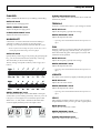
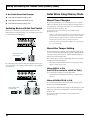
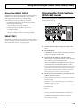
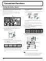
1
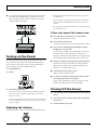
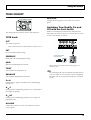
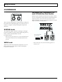
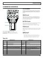
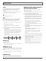
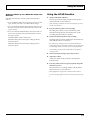
Owner’s Manual
Thank you, and congratulations on your choice of the BOSS ME-50 Guitar Multiple Effects.
Before using this unit, carefully read the sections entitled: “USING THE UNIT SAFELY” (page 2–3) and
“IMPORTANT NOTES” (page 4).
These sections provide important information concerning the proper operation of the unit. Additionally, in order to
feel assured that you have gained a good grasp of every feature provided by your new unit, owner’s manual should
be read in its entirety. The manual should be saved and kept on hand as a convenient reference.
Main features
Simple Operation—Works Like a
Compact Effects Processor
Each effect is controlled with a dedicated knob.
Intuitive operation, similar to that of compact effects
processors, lets you make changes to tones directly.
Multi-Function Expression Pedal
The ME-50 is equipped with an expression pedal that
gives you control over six different specialized pedal
effects. It can also be switched for use as a volume
pedal.
Powerful COSM Drive Sound
Memory Function
Roland’s original “COSM” modeling technology lets
you perform with a wide variety of powerful distortion
effects, from classic vintage sounds, to original
distortion sounds.
You can store up to 30 original tones you have created.
You can also use the pedals in “Memory mode” to call
up stored tones instantly.
COSM (Composite Object Sound Modeling)
Composite Object Sound Modeling (COSM) is Roland’s
innovative and powerful sound modeling technology.
COSM analyzes the many factors that make up the
original sound, such as the electrical and physical
characteristics of the original, and then produces a
digital model that can reproduce the same sound.
Copyright © 2002 BOSS CORPORATION
All rights reserved. No part of this publication
may be reproduced in any form without the
written permission of BOSS CORPORATION.
AUX IN Jack
The AUX IN jack makes it easy to practice along with
CDs, MDs, and other input.
Battery-Powered Operation
The ME-50 can be powered in two ways, with (6) AA
batteries or by using the AC adaptor (optional).
USING THE UNIT SAFELY
The
symbol alerts the user to important instructions
or warnings.The specific meaning of the symbol is
determined by the design contained within the
triangle. In the case of the symbol at left, it is used for
general cautions, warnings, or alerts to danger.
Used for instructions intended to alert
the user to the risk of death or severe
injury should the unit be used
improperly.
Used for instructions intended to alert
the user to the risk of injury or material
damage should the unit be used
improperly.
* Material damage refers
other adverse effects
respect to the home
furnishings, as well
animals or pets.
The
symbol alerts the user to items that must never
be carried out (are forbidden). The specific thing that
must not be done is indicated by the design contained
within the circle. In the case of the symbol at left, it
means that the unit must never be disassembled.
to damage or
caused with
and all its
to domestic
The ● symbol alerts the user to things that must be
carried out. The specific thing that must be done is
indicated by the design contained within the circle. In
the case of the symbol at left, it means that the powercord plug must be unplugged from the outlet.
001
009
• Before using this unit, make sure to read the
instructions below, and the Owner’s Manual.
• Do not excessively twist or bend the power cord,
nor place heavy objects on it. Doing so can
damage the cord, producing severed elements and
short circuits. Damaged cords are fire and shock
hazards!
..........................................................................................................
..........................................................................................................
002c
• Do not open (or modify in any way) the unit or its
AC adaptor.
..........................................................................................................
003
• Do not attempt to repair the unit, or replace parts
within it (except when this manual provides
specific instructions directing you to do so). Refer
all servicing to your retailer, the nearest Roland
Service Center, or an authorized Roland
distributor, as listed on the "Information" page.
..........................................................................................................
004
• Never use or store the unit in places that are:
• Subject to temperature extremes (e.g., direct
sunlight in an enclosed vehicle, near a heating
duct, on top of heat-generating equipment); or
are
• Damp (e.g., baths, washrooms, on wet floors);
or are
• Humid; or are
• Exposed to rain; or are
• Dusty; or are
• Subject to high levels of vibration.
..........................................................................................................
007
• Make sure you always have the unit placed so it is
level and sure to remain stable. Never place it on
stands that could wobble, or on inclined surfaces.
..........................................................................................................
008b
• Use only the specified AC adaptor (PSA series),
and make sure the line voltage at the installation
matches the input voltage specified on the AC
adaptor’s body. Other AC adaptors may use a
different polarity, or be designed for a different
voltage, so their use could result in damage,
malfunction, or electric shock.
..........................................................................................................
2
010
• This unit, either alone or in combination with an
amplifier and headphones or speakers, may be
capable of producing sound levels that could
cause permanent hearing loss. Do not operate for
a long period of time at a high volume level, or at
a level that is uncomfortable. If you experience
any hearing loss or ringing in the ears, you should
immediately stop using the unit, and consult an
audiologist.
..........................................................................................................
011
• Do not allow any objects (e.g., flammable material,
coins, pins); or liquids of any kind (water, soft
drinks, etc.) to penetrate the unit.
..........................................................................................................
012c
• Immediately turn the power off, remove the AC
adaptor from the outlet, and request servicing by
your retailer, the nearest Roland Service Center, or
an authorized Roland distributor, as listed on the
“Information” page when:
• The AC adaptor or the power-supply cord has
been damaged; or
• If smoke or unusual odor occurs
• Objects have fallen into, or liquid has been
spilled onto the unit; or
• The unit has been exposed to rain (or otherwise
has become wet); or
• The unit does not appear to operate normally or
exhibits a marked change in performance.
..........................................................................................................
013
107d
• In households with small children, an adult
should provide supervision until the child is
capable of following all the rules essential for the
safe operation of the unit.
..........................................................................................................
• Never handle the AC adaptor body, or its output
plugs, with wet hands when plugging into, or
unplugging from, an outlet or this unit.
..........................................................................................................
014
• Protect the unit from strong impact.
(Do not drop it!)
..........................................................................................................
015
• Do not force the unit’s power-supply cord to share
an outlet with an unreasonable number of other
devices. Be especially careful when using
extension cords—the total power used by all
devices you have connected to the extension
cord’s outlet must never exceed the power rating
(watts/amperes) for the extension cord. Excessive
loads can cause the insulation on the cord to heat
up and eventually melt through.
..........................................................................................................
016
• Before using the unit in a foreign country, consult
with your retailer, the nearest Roland Service
Center, or an authorized Roland distributor, as
listed on the “Information” sheet.
..........................................................................................................
019
• Batteries must never be recharged, heated, taken
apart, or thrown into fire or water.
108b
• Before moving the unit, disconnect the AC
adaptor and all cords coming from external
devices.
..........................................................................................................
109b
• Before cleaning the unit, turn off the power and
unplug the AC adaptor from the outlet.
..........................................................................................................
110b
• Whenever you suspect the possibility of lightning
in your area, disconnect the AC adaptor from the
outlet.
..........................................................................................................
111
• If used improperly, batteries may explode or leak
and cause damage or injury. In the interest of
safety, please read and observe the following
precautions (p. 6).
1
• Carefully follow the installation instructions for
batteries, and make sure you observe the correct
polarity.
2
• Avoid using new batteries together with used
ones. In addition, avoid mixing different types
of batteries.
3
• Remove the batteries whenever the unit is to
remain unused for an extended period of time.
..........................................................................................................
5
• If a battery has leaked, use a soft piece of cloth
or paper towel to wipe all remnants of the
discharge from the battery compartment. Then
install new batteries. To avoid inflammation of
the skin, make sure that none of the battery
discharge gets onto your hands or skin. Exercise
the utmost caution so that none of the discharge
gets near your eyes. Immediately rinse the
affected area with running water if any of the
discharge has entered the eyes.
101b
• The unit and the AC adaptor should be located so
their location or position does not interfere with
their proper ventilation.
..........................................................................................................
102d
• Always grasp only the output plug or the body of
the AC adaptor when plugging into, or
unplugging from, this unit or an outlet.
..........................................................................................................
103b
• Any accumulation of dust between the AC
adaptor and the power outlet can result in poor
insulation and lead to fire. Periodically wipe away
such dust with a dry cloth. Also, disconnect the
power plug from the power outlet whenever the
unit is to remain unused for an extended period of
time.
..........................................................................................................
6
• Never keep batteries together with metallic
objects such as ballpoint pens, necklaces,
hairpins, etc.
..........................................................................................................
112
• Used batteries must be disposed of in compliance
with whatever regulations for their safe disposal
that may be observed in the region in which you
live.
..........................................................................................................
104
• Try to prevent cords and cables from becoming
entangled. Also, all cords and cables should be
placed so they are out of the reach of children.
..........................................................................................................
106
• Never climb on top of, nor place heavy objects on
the unit.
..........................................................................................................
3
IMPORTANT NOTES
291a
In addition to the items listed under “USING THE UNIT SAFELY” on page 2–3, please read and observe the following:
Power Supply: Use of Batteries
Maintenance
301
401a
• Do not use this unit on the same power circuit with any
device that will generate line noise (such as an electric
motor or variable lighting system).
• For everyday cleaning wipe the unit with a soft, dry cloth
or one that has been slightly dampened with water. To
remove stubborn dirt, use a cloth impregnated with a
mild, non-abrasive detergent. Afterwards, be sure to wipe
the unit thoroughly with a soft, dry cloth.
302
• The AC adaptor will begin to generate heat after long
hours of consecutive use. This is normal, and is not a
cause for concern.
303a
• The use of an AC adaptor is recommended as the unit’s
power consumption is relatively high. Should you prefer
to use batteries, please use the alkaline type.
304a
• When installing or replacing batteries, always turn off the
power on this unit and disconnect any other devices you
may have connected. This way, you can prevent
malfunction and/or damage to speakers or other devices.
402
• Never use benzine, thinners, alcohol or solvents of any
kind, to avoid the possibility of discoloration and/or
deformation.
Additional Precautions
551
• Batteries are supplied with the unit. The life of these
batteries may be limited, however, since their primary
purpose was to enable testing.
• Please be aware that the contents of memory can be
irretrievably lost as a result of a malfunction, or the
improper operation of the unit. To protect yourself against
the risk of loosing important data, we recommend that
you periodically save a backup copy of important data
you have writed on the paper.
306b
307
552
• Before connecting this unit to other devices, turn off the
power to all units. This will help prevent malfunctions
and/or damage to speakers or other devices.
• Unfortunately, it may be impossible to restore the contents
of data that was stored in the unit’s memory once it has
been lost. Roland Corporation assumes no liability
concerning such loss of data.
Placement
553
351
• Using the unit near power amplifiers (or other equipment
containing large power transformers) may induce hum.
To alleviate the problem, change the orientation of this
unit; or move it farther away from the source of interference.
352a
• This device may interfere with radio and television
reception. Do not use this device in the vicinity of such
receivers.
352b
• Noise may be produced if wireless communications
devices, such as cell phones, are operated in the vicinity of
this unit. Such noise could occur when receiving or initiating a call, or while conversing. Should you experience
such problems, you should relocate such wireless devices
so they are at a greater distance from this unit, or switch
them off.
354a
• Do not expose the unit to direct sunlight, place it near
devices that radiate heat, leave it inside an enclosed
vehicle, or otherwise subject it to temperature extremes.
Excessive heat can deform or discolor the unit.
• Use a reasonable amount of care when using the unit’s
buttons, sliders, or other controls; and when using its jacks
and connectors. Rough handling can lead to malfunctions.
556
• When connecting / disconnecting all cables, grasp the
connector itself—never pull on the cable. This way you
will avoid causing shorts, or damage to the cable’s
internal elements.
558a
• To avoid disturbing your neighbors, try to keep the unit’s
volume at reasonable levels. You may prefer to use
headphones, so you do not need to be concerned about
those around you (especially when it is late at night).
559a
• When you need to transport the unit, package it in the box
(including padding) that it came in, if possible. Otherwise,
you will need to use equivalent packaging materials.
562
• Use a cable from Roland to make the connection. If using
some other make of connection cable, please note the
following precautions.
• Some connection cables contain resistors. Do not use
cables that incorporate resistors for connecting to this
unit. The use of such cables can cause the sound level
to be extremely low, or impossible to hear. For information on cable specifications, contact the manufacturer of the cable.
355b
• When moved from one location to another where the
temperature and/or humidity is very different, water
droplets (condensation) may form inside the unit. Damage
or malfunction may result if you attempt to use the unit in
this condition. Therefore, before using the unit, you must
allow it to stand for several hours, until the condensation
has completely evaporated.
4
988
• Security Slot ( )
http://www.kensington.com/
Contents
USING THE UNIT SAFELY ................... 2
Saving and Loading the
Created Tones (Memory Mode) ....... 20
IMPORTANT NOTES .......................... 4
Switching Between Manual and Memory Mode ....... 20
Playing Sounds ................................ 6
About the Patch....................................................... 20
Installing Batteries .................................................... 6
Write Procedure ...................................................... 21
Making the Connections........................................... 6
Calling Up and Using Stored Tones
(Patch Change) ........................................................ 21
Switching Numbers................................................... 21
Switching Banks......................................................... 21
Switching Banks with the Foot Switch ................... 22
Turning on the Power ............................................... 7
Adjusting the Volume................................................. 7
Turning Off the Power .............................................. 7
Using the Effects ............................... 8
About the Effect Connection Sequence.................. 8
TONE MODIFY ........................................................... 9
Switching Tone Modify On and Off
with the Foot Switch ................................................... 9
COMPRESSOR ........................................................ 10
Switching the Compressor On and Off
with the Foot Switch ................................................. 10
Notes When Using Memory Mode ......................... 22
About Tone Changes................................................. 22
About the Tempo Setting.......................................... 22
About the DELAY HOLD......................................... 23
DELAY TAP ............................................................. 23
Changing the Patch Settings
(Patch Edit mode).................................................... 23
Convenient Functions...................... 24
OVERDRIVE/DISTORTION...................................... 11
Tuning the Guitar (Tuner) ....................................... 24
MODULATION.......................................................... 12
Adding an Effect Synchronized to the
Performance Tempo .................................................. 14
Practicing Along with CDs and MDs (AUX IN)...... 25
DELAY ...................................................................... 15
Adding a Delay Synchronized to the
Performance Tempo .................................................. 16
Using the HOLD Function ....................................... 17
NS (Noise Suppressor) ........................................... 18
Appendices .................................... 26
Returning the ME-50 to Its Factory Settings
(Factory Reset) ........................................................ 26
Adjusting the Expression Pedal ............................ 26
Troubleshooting ...................................................... 27
Specifications .......................................................... 28
REVERB ................................................................... 18
Pedal......................................................................... 19
Using the Pedal as a Volume Pedal ........................ 19
Using the Pedal as an Expression Pedal................. 19
Patch List........................................ 29
Factory Settings.............................. 30
Blank Chart.................................... 32
Index ............................................. 34
Conversions Used in This Manual
●
Words in square brackets [ ] indicate panel buttons or knobs.
(Example)
●
[VARIATION]:
VARIATION button
[WRITE]:
WRITE button
(p. **) indicates a reference page.
5
Playing Sounds
Installing Batteries
* Batteries are supplied with the unit. The life of these batteries
may be limited, however, since their primary purpose was to
enable testing.
Insert the included batteries as shown in figure, being careful
to orient the batteries correctly.
fig.0010
Making the Connections
The ME-50 is not equipped with any internal amplifier or
speakers. To listen to sound with the ME-50, connect it to a
guitar amp, stereo headphones, or other such sound
equipment.
* To prevent malfunction and/or damage to speakers or other
devices, always turn down the volume, and turn off the power
on all devices before making any connections.
fig.0020
Stereo
Headphones
AC Adaptor
(PSA series: optional)
Electric Guitar
CD/MD
Player, etc.
• When turning the unit upside-down, get a bunch of
newspapers or magazines, and place them under the
four corners or at both ends to prevent damage to the
buttons and controls. Also, you should try to orient the
unit so no buttons or controls get damaged.
• When turning the unit upside-down, handle with care to
avoid dropping it, or allowing it to fall or tip over.
Guitar Amp
●
• Make sure the “+” and “-” ends of the batteries are
oriented correctly.
• When the batteries run down, the POWER indicator gets
dim. If this happens, replace with new batteries.
To prevent the inadvertent disruption of power to your
unit (should the plug be pulled out accidentally), and to
avoid applying undue stress to the AC adaptor jack,
anchor the power cord using the cord hook, as shown in
the illustration.
fig.0040
• When replacing the batteries, use six AA type.
• Avoid using new batteries together with used ones. In
addition, avoid mixing different types of batteries. Doing
so can result in fluid leakage.
• Battery life can vary depending on battery type.
Continuous usage time under battery power is about 12
hours with alkaline batteries and about 3.5 hours with
carbon batteries.
(This may vary according to usage conditions.)
6
●
When outputting monaurally, connect a cable only to the
OUTPUT L (MONO) jack.
●
Do not use a cable containing a resistor to connect CD or
MD players to the AUX IN jack.
●
When you use the LINE/PHONES jack, the built-in
guitar-amp simulator lets you enjoy impressive guitar
sound, even with headphones.
Playing Sounds
●
Use a special cable (the optional PCS-31) to send output
from the LINE/PHONES jack to equipment such as a
mixer. Using an ordinary cable will cause only the leftchannel sound to be output.
fig.0030
* Raising the MASTER LEVEL knob too much may result in
sound distortion.
* When the effects are all off, input and output are at the same
levels as when the MASTER LEVEL knob is at the center
position.
* The setting of the MASTER LEVEL knob is stored in memory
for each Patch (p. 20).
If There Is No Sound/If the Volume is Low
PCS-31
White
Red
(L)
(R)
●
Are connections to other devices correctly made?
Check the connections once more.
●
Is the volume turned down?
Check the volume levels on any connected amp or mixer.
●
If you can hear sounds, it may be that there is a short in
the cable used to connect the amp or other device, or
perhaps a mistake in an external device’s settings. Check
the connecting cables and external devices once more.
Turning on the Power
Once the connections have been completed, turn on power to
your various devices in the order specified. By turning on
devices in the wrong order, you risk causing malfunction
and/or damage to speakers and other devices.
Can you hear sound through the headphones when
headphones are connected?
●
Has the level been lowered with the expression pedal?
Sounds are not output when the toe of the expression
pedal is in the raised position while the pedal is set to
function as a volume pedal. (p. 19)
1. (CD/MD Player)
2. ME-50
●
Is the ME-50 in Tuner mode (p. 24)?
Output is muted in Tuner mode.
fig.0041
●
Is a cable containing a resistor being used to connect a
CD or MD player to the AUX IN jack?
Using a cable containing a resistor may prevent sound
from CD and MD players from being audible.
3. Guitar Amp / Stereo, Etc.
* Turn up the volume on amps and other equipment only after
all connections are completed and the power for connected
devices is turned on.
* This unit is equipped with a protection circuit. A brief interval
(several seconds) after power up is required before the unit will
operate normally.
Turning Off the Power
1. Turn down the volume of the ME-50 and any connected
device.
2. Turn off the power to Guitar Amp / Stereo, Multitrack
Recorder, etc.
3. Tuen the ME-50’s power off.
Adjusting the Volume
Adjust the ME-50’s volume with the MASTER LEVEL knob.
fig.0050
7
Using the Effects
When the power is turned on, the ME-50 always switches to Manual mode, and the OVERDRIVE/DISTORTION,
MODULATION, and DELAY are switched off.
* When the DELAY TYPE is set to HOLD, the DELAY indicator goes on, the DELAY pedal’s indicator flashes at a fixed interval,
indicating recording standby is enabled. (p. 17)
All product names mentioned in this document are trademarks or registered trademarks of their respective owners.
Those companies are not affiliated with BOSS and have not licenced or authorized BOSS’s ME-50. Their marks are used
solely to identify the equipment whose sound is simulated by BOSS’s ME-50.
About the Effect Connection Sequence
The ME-50 automatically selects the optimum sequence for connecting the effects according to the effect (p. 19) you select with the
expression pedal.
● When WAH, RING MOD, +1OCTAVE, or -1OCTAVE is Selected
fig.0060
TONE MODIFY
NS
EXPRESSION
VOLUME
(PEDAL)
COMPRESSOR
MODULATION
OVERDRIVE /
DISTORTION
DELAY
REVERB
● When RESONANCE and VOICE is Selected
fig.0070
TONE MODIFY
NS
COMPRESSOR
VOLUME
(PEDAL)
OVERDRIVE /
DISTORTION
MODULATION
EXPRESSION
DELAY
REVERB
Also, when the MODULATION type is TREMOLO or UNI-V, MODULATION is connected before OVERDRIVE/DISTORTION.
(Example) EXPRESSION: WAH; MODULATION: TREMOLO
fig.0080
TONE MODIFY
OVERDRIVE /
DISTORTION
8
WAH
(EXPRESSION)
NS
COMPRESSOR
VOLUME
(PEDAL)
TREMOLO
(MODULATION)
DELAY
REVERB
Using the Effects
TONE MODIFY
fig.0090
TONE MODIFY Indicator
ACOUSTIC
Changes the electric guitar’s tone to that of an acoustic
guitar.
Switching Tone Modify On and
Off with the Foot Switch
This changes the characteristics of the connected guitar.
TYPE knob
With a foot switch (the optional FS-5U) connected to the
FOOT SW jack on the rear panel, you can use the foot switch
to switch Tone Modify on and off.
fig.0100
OFF
The sound is bypassed.
* When switched OFF, the TONE MODIFY indicator goes out.
FAT
Fat tone with boosted mid range.
PRESENCE
Set the polarity switch
as shown below.
Bright tone with boosted high-mid range.
MILD
Mild tone with the high end cut back.
TIGHT
* When in Memory mode, the bank-switching function is
enabled (p. 22).
Tone with the low frequencies cut.
ENHANCE
Tone with the high frequencies boosted.
S
By connecting with a special cable (the optional PCS-31),
you can connect two foot switches, one for Tone Modify
ON/OFF, and one to switch the Compressor on and off
(p. 10).
H
Changes from a single-coil pickup tone to a humbucking
pickup tone.
H
S
Changes from a humbucking pickup tone to a mixed tone of
two single-coil pickups.
H
HF
Changes from a humbucking pickup tone to a single-coil
pickup half tone.
HOLLOW
Adds body resonance to create a tone like that of an fullacoustic guitar.
9
Using the Effects
COMPRESSOR
fig.0110
COMPRESSOR Indicator
Switching the Compressor On
and Off with the Foot Switch
With the special cable (the optional PCS-31) used to connect
two foot switches (the optional FS-5U) to the FOOT SW jack
on the rear panel, you can use one foot switch for Tone
Modify ON/OFF, and one to switch the Compressor on and
off (p. **). Connect as shown below.
This is an effect that produces a long sustain by evening out
the volume level of the input signal. You can also use it as a
“limiter” to suppress only the sound peaks and prevent
distortion.
fig.0120
SUSTAIN knob
This adjusts the depth of the effect. Turning it to the right
(clockwise) produces a longer sustain. When using this as a
limiter, turn the SUSTAIN knob to the left
(counterclockwise).
* When not using the Compressor, turn the SUSTAIN knob to
OFF. When switched OFF, the COMPRESSOR indicator
goes out.
LEVEL knob
Adjusts the volume level when the Compressor is on. Use
this in achieving a volume balance when switching the
Compressor on and off.
10
PCS-31
White
Red
Set the polarity switch
as shown below.
TONE MODIFY COMPRESSOR
On/Off
On/Off
* When in Memory mode, the bank-switching function is
enabled (p. 22).
Using the Effects
OVERDRIVE/DISTORTION
fig.0130
OVERDRIVE/DISTORTION Indicator
OD/DS pedal
Each time you press the pedal, the effect switches through
Overdrive/Distortion ON and OFF. When switched on, the
OVERDRIVE/DISTORTION indicator and pedal indicator
light up.
DRIVE knob
Adjusts the amount of distortion. Turning the knob to the
right (clockwise) creates a stronger distortion and increases
the volume. Turning this all the way to the TURBO range
increases the effect even more.
BOTTOM knob
Pedal Indicator
Adjusts the low frequency range. Turning the knob to the left
(counterclockwise) cuts the low end more; the low
frequencies are boosted as the knob is turned to the right.
OD/DS Pedal
TONE knob
Adjusts the tone. Turning the knob to the left creates a milder
sound; a sharper sound is produced as the knob is turned to
the right.
These are effects that distort the sound.
You can use the TYPE knob in combination with
[VARIATION] to get 22 different types of distortion.
LEVEL knob
Adjusts the volume.
* Noise may be mixed in if you turn the LEVEL knob up too
high. Adjust the LEVEL knob so that the apparent volume
level remains the same whether the effects are on or off.
Type List
[VARIATION] Off
[VARIATION] Lit
OD-1
Models the BOSS OD-1.
NATURAL
OD-2
Models the BOSS OD-2.
CRUNCH
BD-2
Models the BOSS BD-2.
LEAD
Models the BOSS DS-1.
DS-1
Models the BOSS MT-2.
MT-2
SCREAM Models the Ibanez TS-808 TUBESCREAMER.
LOUD
METAL
MODERN OD
DST+
Models the MXR DISTORTION+.
STACK
GUV
RAT
MUFF
FACE
Models the Marshall GUV’NOR.
Models the Proco RAT.
Models the Electro-Harmonix Big Muff π.
Models the FUZZFACE.
Hi GAIN
MODERN DS
SQUARE
OCT FUZZ
Overdrive that gives a more natural sounding distortion.
A lustrous crunch sound with an added element of
amp distortion.
Produces a distortion sound with both the smoothness of an overdrive along with a deep distortion.
A heavy distortion with a boosted low end.
An intense, radical distortion sound.
Overdrive with special mid range tone.
A fat sound with an added element of a stack
amp’s distortion.
Sound of Overdrive through a stack amp.
Sound of a large high gain amp.
Synth square wave sound.
Fuzz sound produced by octave harmonics.
11
Using the Effects
MODULATION
fig.0140
MODULATION Indicator
DEPTH/HARMONY knob
Adjusts the depth of modulation.
E.LEVEL/RESONANCE knob
Adjusts the volume of the chorus sound.
ST CHORUS 1
This is a stereo chorus effect that adds different chorus
sounds to L and R.
RATE/KEY knob
Adjusts the rate of modulation.
DEPTH/HARMONY knob
Adjusts the depth of modulation.
Pedal Indicator
E.LEVEL/RESONANCE knob
Adjusts the volume of the chorus sound.
MOD Pedal
ST CHORUS 2
This is a stereo chorus effect produced by synthesizing the
spatial characteristics of the direct sound and the effect
sound.
RATE/KEY knob
Adjusts the rate of modulation.
An effect that broadens sound and adds undulations is called
“modulation.”
DEPTH/HARMONY knob
The ME-50 comes with 11 different types of Modulation
effects. Select any one of these as the effect to be used.
E.LEVEL/RESONANCE knob
Adjusts the depth of modulation.
Adjusts the volume of the chorus sound.
MOD pedal
Depress the pedal to toggle Modulation on/off.
When switched on, the MODULATION indicator and pedal
indicator light up.
PHASER
By adding varied-phase portions to the direct sound, adds a
twisting “warp” effect to the sound.
RATE/KEY knob
TYPE knob
Select the effect to be used from the eleven effects available.
Adjusts the rate of phaser effect.
DEPTH/HARMONY knob.
Adjusts the depth of phaser effect.
CHORUS
E.LEVEL/RESONANCE knob
This chorus effect outputs the same sound from both L and
R.
Adjusts the amount of resonance.
“Chorus” adds a subtle sway to the guitar sound for a
beautiful sound featuring more breadth and fullness.
RATE/KEY knob
Adjusts the rate of modulation.
12
Using the Effects
FLANGER
E.LEVEL/RESONANCE knob
Adds a undulation like that of a jet ascending or decending.
Adjusts the volume balance between the direct sound and
the harmony sound.
RATE/KEY knob
Adjusts the rate of flanging effect.
TREMOLO
DEPTH/HARMONY knob
Tremolo is an effect that creates a cyclic change in volume.
Adjusts the depth of flanging effect.
RATE/KEY knob
E.LEVEL/RESONANCE knob
Adjusts the frequency (speed) of the change.
Adjusts the amount of resonance.
DEPTH/HARMONY knob
Adjusts the depth of the effect.
HARMONIST
“Harmonist” is an effect which the amount of shifting is
adjusted according to an analysis of the guitar input,
allowing you to create harmonics based on diatonic scales.
* Because of the need to analyze the pitch, chords (two or more
sounds played simultaneously) cannot be played.
RATE/KEY knob
Specify the key of the song you are playing. By specifying the
key, you can create harmonies that fit the key of the song.
* Operating the E.LEVEL/RESONANCE knob produces no
effect.
PAN
With the volume level of the left and right sides alternately
changing, when playing sound in stereo, you can get an
effect that makes the guitar sound appear to fly back and
forth between the speakers.
RATE/KEY knob
The selected key is shown in the display.
Adjusts the frequency (speed) of the change.
The key setting corresponds to the key of the song (#, b) as
follows.
DEPTH/HARMONY knob
fig.0150
Adjusts the depth of the effect.
* Operating the E.LEVEL/RESONANCE knob produces no
effect.
VIBRATO
This effect creates vibrato by slightly modulating the pitch.
RATE/KEY knob
Adjusts the rate of the vibrato.
DEPTH/HARMONY knob
Adjusts the depth of the vibrato.
DEPTH/HARMONY knob
This determines the pitch of the sound added to the input
sound, when you are making a harmony. It allows you to set
it by up to 1 octave higher or lower than the input sound.
When set to “0,” this yields a “detuned” effect that adds
sound of slightly different pitch to the input sound.
fig.0160
* Operating the E.LEVEL/RESONANCE knob produces no
effect.
UNI-V
Although this resembles a phaser effect, it also provides a
unique undulation that you can’t get with a regular phaser.
RATE/KEY knob
Adjusts the rate of the UNI-V effect.
DEPTH/HARMONY knob
Adjusts the depth of the UNI-V effect.
-1Octave
6th
Detune
+1 Octave
E.LEVEL/RESONANCE knob
Adjusts the volume of the UNI-V effect.
13
Using the Effects
ROTARY
Produces the effect of a rotary speaker.
RATE/KEY knob
Adjusts the speed of rotation for the speaker.
DEPTH/HARMONY knob
Adjusts the depth of the rotary effect.
E.LEVEL/RESONANCE knob
Adjusts the volume of the rotary effect.
Adding an Effect Synchronized to
the Performance Tempo
When any effect other than HARMONIST is selected, you
can set the tempo so you get an effect that is synchronized to
the performance tempo.
* The allowable rate cycles for the tempo settings range from 62
ms to 2000 ms.
1. Hold down the MOD pedal for at least two seconds.
• If the MOD pedal is pressed when the effect is on, the
pedal indicator goes out, and the effect is turned off.
• If the MOD pedal is pressed when the effect is off, the
pedal indicator turns red, and the effect is turned on.
When you continue to depress the pedal, after two
seconds the pedal’s indicator starts to flash, and the
tempo can then be set with the effect on.
Here, the tempo is indicated by the value set with the
RATE/KEY knob.
2. Press the MOD pedal in timing with the tempo more
than two times.
The tempo is set according to the time interval between
each press of the pedal. The pedal indicator flashes in
time with the tempo.
Setting the RATE near the desired tempo beforehand
allows you to make faster and more natural tempo
settings.
3. Hold down the MOD pedal for at least two seconds to
complete the tempo setting.
The effect goes on, and instead of flashing, the pedal
indicator will light.
* If you move the RATE/KEY knob after finishing this setting,
the rate corresponding to the knob position takes effect.
14
Using the Effects
DELAY
fig.0170
DELAY Indicator
0-30 ms
Delay sound of 0 to 30 ms delay time.
25-125 ms
Delay sound of 25 to 125 ms delay time.
100-500 ms
Delay sound of 100 to 500 ms delay time.
400-2000 ms
Delay sound of 400 to 2000 ms delay time.
ANALOG
Pedal Indicator
This gives a mild analog delay sound. The delay time can be
set within the range of 100 ms to 500 ms.
SLOW ECHO
DELAY Pedal
This produces an effect combining a volume-swell sound
with delay. The delay time can be set within the range of 200
ms to 1000 ms.
PAN
This effect adds delayed sound to the direct sound, giving
more body to the sound or creating special effects.
DELAY pedal
The Delay is switched on or off each time you press the
pedal. When switched on, the DELAY indicator and pedal
indicator light up.
* DELAY ON/OFF switches the Delay at the input to provide a
more natural effect. For this reason, if the FEEDBACK is
turned up when the Delay is turned off, the delay sound will
remain briefly.
TYPE knob
Sets the type of the delay
* When a setting other than HOLD is selected, you can use the
DELAY pedal to input the tempo, and set the delay time
synchronized to the performance tempo.
“TAP” (p. 16)
A panned delay in which the repeated sounds come
alternately from the left and right channels. The delay time
can be set within the range of 200 ms to 1000 ms.
* When using the ME-50 in mono, the panning delay is not
effective, even when PAN is selected.
SPACE PAN
This is a panning delay that gives an even wider spatial effect
than PAN. The delay time can be set within the range of 200
ms to 1000 ms.
* When using the ME-50 in mono, or when using headphones,
the panning delay is not effective, even when SPACE PAN is
selected.
REVERSE
This produces an effect where the sound is played back in
reverse.
You can get two different effects, “direct sound + effect
sound,” or “effect sound only,” depending on the position of
the E.LEVEL knob. When the E.LEVEL knob is turned up to
MAX, the unit switches to “effect sound only.”
The delay time can be set within the range of 400 ms to 2000
ms.
“Adding Synchronized Delay to the Performance Tempo”
(p. 16)
15
Using the Effects
HOLD
Up to 2 seconds of performance content is recorded, then
played back repeatedly. You can also layer this as you
perform something else, then record these together
(overdub).
You can keep the recorded content playing continuously as
backing and produce other special effects.
Adding a Delay Synchronized to
the Performance Tempo
Using tempo input, the delay time can be set within the
range of 62 ms to 2000 ms.
You can set this regardless of whether the effect is on or off.
1. Select the delay type. (except HOLD, TAP)
2. Hold down the DELAY pedal for at least two seconds.
“Using the HOLD Function”
TAP
This is a tempo delay that lets you set a dotted eighth note
delay time for the performance tempo by pressing the
DELAY pedal in time with the performance tempo.
* The delay time can be set within the range of 46.5 ms to 1500
ms.
1. Set the TYPE knob to ‘TAP”
The pedal indicator flashes in time with the current
tempo.
2. Press the DELAY pedal in timing with the tempo more
than two times.
The reference tempo is determined by the time interval
between each press of the pedal. The reference tempo is
calculated in terms of quarter notes, and the delay time
setting is the dotted eight note as referenced to the
reference tempo.
The pedal indicator flashes in time with the tempo.
fig.0180
Timing
Delay Sound
TIME knob
Adjuts the delay time.
* When the type is set to “HOLD” or “TAP ,” operating the
TIME knob produces no effect.
FEEDBACK knob
Adjusts the amount of feedback (number of repeats). Turning
the knob to the right increases the number of times the sound
repeats.
* When the type is set to ”HOLD,” operating the FEEDBACK
knob produces no effect.
E.LEVEL knob
Adjusts the volume of the delay sound. When TYPE is set to
REVERSE, this adjusts the balance of direct and effect sound.
16
• If the DELAY pedal is pressed when the effect is on, the
pedal indicator goes out, and the effect is turned off.
• If the DELAY pedal is pressed when the effect is off, the
pedal indicator turns red, and the effect is turned on.
When you continue to depress the pedal, after two
seconds the pedal’s indicator starts to flash, and the
tempo can then be set with the effect on.
Here, the delay time is indicated by the value set with
the TIME knob.
3. Press the DELAY pedal in timing with the tempo more
than two times.
The delay time is set according to the time interval
between each press of the pedal.
The pedal indicator flashes in time with the tempo.
* Press the pedal to set the tempo while no guitar sound is
playing.
* When the type is set to “PAN” or “SPACE PAN,” the delay
time is set to half the interval between the presses of the pedal.
4. Hold down the pedal switch for at least two seconds to
complete the tempo setting.
The effect goes on, and instead of flashing, the pedal
indicator will light.
* The tempo may become confused momentarily when you go
from Step 3 to Step 4.
* If you move the TIME knob after finishing this setting, the
delay time corresponding to the knob position takes effect.
Using the Effects
Write Procedures (p. 21) When the Tempo Has
Been Set
The delay time stored in a Patch (p. 20) is determined as
follows.
• If it is within the delay time range that can be set for the
type currently selected, it is stored without change.
• If it exceeds the maximum delay time that can be set for
the type currently selected, the maximum value for the
type is stored.
• If it is less than the minimum delay time that can be set
for the type currently selected, the minimum value for
the type is stored.
(Example) When TYPE is 100–500 ms
When the delay time for the tempo setting is 600 ms:
Stored as 500 ms.
When the delay time for the tempo setting is 80 ms:
Stored as 100 ms.
Using the HOLD Function
1. Set the TYPE knob to HOLD.
The unit goes into recording standby and the pedal’s
indicator flashes at a fixed interval.
* After switching to HOLD, wait two seconds before you carry
out the next operation.
2. Press the DELAY pedal to start recording.
Recording starts when you press the DELAY pedal.
Hold down the pedal switch for the duration of the
recording (the pedal indicator flashes).
3. Release the DELAY pedal to stop recording.
Playback of the recorded content begins simultaneously
(the CHECK indicator remains lit).
* The maximum recording time is 2 seconds. If the DELAY
pedal is held down for more than 2 seconds, the recording stops
automatically, and the recorded content is then played back.
* An oscillating sound may be audible with extremely short
recording times.
4. When layering recordings, repeat Steps 2 and 3.
5. Adjust the volume
Adjust the volume of the playback sound with the
E.LEVEL knob.
6. Press the pedal switch to stop the playback (the pedal
indicator goes out).
The unit returns to recording standby, and the pedal’s
indicator flashes at a fixed interval.
* When playback is stopped, the recorded content is erased.
* To start recording again, wait two seconds, then carry out step
2.
17
Using the Effects
NS (Noise Suppressor)
REVERB
fig.0190
fig.0200
NS Indicator
This effect reduces the noise and hum picked up by guitar
pickups. Since it suppresses the noise in synchronization
with the envelope of the guitar sound (the way in which the
guitar sound decays over time), it has very little effect on the
guitar sound, and does not harm the natural character of the
sound.
THRESHOLD knob
Adjust this parameter as appropriate for the volume of the
noise. If the noise level is high, a higher setting is
appropriate. If the noise level is low, a lower setting is
appropriate. Adjust this value until the decay of the guitar
sound is as natural as possible.
* Turn the knob to OFF when not using the noise suppressor.
When switched OFF, the NS indicator goes out.
* High settings for the threshold parameter may result in there
being no sound when you play with your guitar volume
turned down.
REVERB Indicator
This effect adds reverberation to the sound.
Use the knob to switch to any of four different reverb,
ROOM, HALL, SPRING, or MOD. You can adjust the
amount of effect applied according to the knob position.
* The panel markings for ROOM, HALL, SPRING, or MOD
are for approximate settings. Check the sound of the effects as
you make adjustments.
* The indicator is lit when Reverb is on, and goes off when
Reverb is turned off.
ROOM
This simulates the reverb sound of a smaller room.
HALL
This simulates the reverb sound of a larger hall.
SPRING
This simulates the sound of a guitar amp’s built-in spring
reverb.
MOD
This is a reverb that adds modulation to the hall reverb to
produce an extremely pleasant reverb sound.
18
Using the Effects
Pedal
You can select one of the following effects with the
expression pedal.
fig.0210
PEDAL MODE Indicator
WAH
The effect will function as a pedal wah.
RESONANCE
This completely original effect offers enhancements on the
characteristic resonances produced by analog synth filters.
You can make the setting that determines whether the ME50’s expression pedal functions as a volume pedal or as an
expression pedal. In addition, when using it as an expression
pedal, you can use it to control one of the special pedal
effects that you select.
Using the Pedal as a Volume Pedal
When using the expression pedal as a volume pedal, press
the expression pedal all the way forward and then give it a
stronger push, the PEDAL MODE indicator goes off.
fig.0220
Strongly pressing
Not Lit
Using the effect in combination with the OVERDRIVE/
DISTORTION TYPE set to “SQUARE” produces a sound like
a synthesizer.
And using it together with delay, chgorus, and reverb makes
them even more effective.
VOICE
A further advancement beyond the BOSS HUMANIZER, this
effect produces “talking” modulation sounds and realistic
human voice sounds.
RING MOD
This is an effect that crosses the ME-50’s internal oscillator
with the guitar source sound to change the sound to a
metallic sound devoid of any feeling of pitch.
Pressing the pedal down even more changes the internal
oscillator’s frequency, creating a particular undulation
sound.
* Because of the need to analyze the pitch, chords (two or more
sounds played simultaneously) cannot be played.
+1 OCTAVE
The volume decreases as the pedal’s toe is raised, and
increases when the pedal is pressed down.
Using the Pedal as an Expression Pedal
When using the pedal as an expression pedal, press the
expression pedal all the way forward and then give it a
stronger push, the PEDAL MODE indicator lights up.
fig.0230
Strongly pressing
Lit
Allows the pitch to be raised up to one octave above the
original guitar sound.
* Because of the need to analyze the pitch, chords (two or more
sounds played simultaneously) cannot be played.
-1 OCTAVE
Allows the pitch to be lowered up to one octave below the
original guitar sound.
* Because of the need to analyze the pitch, chords (two or more
sounds played simultaneously) cannot be played.
19
Saving and Loading the Created Tones (Memory Mode)
The ME-50 features a “Memory mode” that allows you to
store the various settings within the ME-50 itself, and then
call up and use the settings.
Switching Between Manual
and Memory Mode
The mode in which the tone produced reflects the panel
settings just as they are is called “Manual mode.” A dot
appears in the display when the ME-50 is in Manual mode.
fig.0240
About the Patch
When actually performing on a guitar, a variety of tones are
required to suit whatever the situation may be. The effects
that you may want to have turned on and parameter settings
for such effects vary according to the selected tone.
With the ME-50, you can set these parameters, volume levels,
and so on, store a number of the aggregate settings in
memory, and use the pedals to switch the stored settings,
allowing you to change tones instantly.
Such stored sets of settings are known as “Patches.” You can
create up to 30 Patches.
The thirty patches are divided into ten “banks,” each of
which contains three patches.
fig.0260
Bank 0
Lit
Bank 3
Bank 2
●
When switching from Manual mode to Memory mode,
press the No. 2 and No. 3 pedals simultaneously; this
causes the MEMORY indicator to light up (and the dot
in the display disappears).
fig.0250
Patch
Bank 1
Patch
Patch
Patch
Patch
Patch
* The setting for the MASTER LEVEL knob is also stored
individually for each patch.
Press simultaneously
Lit
●
Pressing the No. 2 and 3 pedals at the same time while
in Memory mode switches you to Manual mode.
* Manual mode is the power-up default mode of the ME-50.
20
Saving and Loading the Created Tones (Memory Mode)
Write Procedure
The “Write procedure” enables you to save the created tone
settings using the panel knobs and pedals, MASTER LEVEL
knob setting, and expression pedal settings to Patches.
* You can carry out the Write procedure in both Manual mode
and Memory mode.
* If the Write procedure is not carried out, then the tone you
have created is erased when the power is turned off or when
you switch to a different Patch.
Calling Up and Using Stored
Tones (Patch Change)
To switch patches, use BANK [
pedals (1–3).
][
] and the number
* Bank 1, Number 1 is always selected at first when Memory
mode is entered after the power is turned on.
Switching Numbers
fig.0270
2 1,3
When the number pedal (1) is pressed, the number indicator
(2) above the pedal lights up, the patch with that number in
the currently selected group and bank is called up, and the
tone is switched instantly.
fig.0280
(2)
2
1. Press [WRITE].
The MEMORY indicator flashes. At the same time, the
bank indication in the display and the pedal indicator
flash, and the currently selected Patch Bank and Number
are shown.
2. Select the Patch to be used as the save destination.
■
Press BANK [
■
Press a number pedal (1-3) to select the number.
][
] to select the bank.
* To stop the Write procedure, press [EDIT/EXIT], and return
to the previous mode.
3. Press [WRITE] once more.
The tone is stored, and Memory mode is then enabled
(the MEMORY indicator lights up).
(1)
(2)
(1)
(2)
(1)
Switching Banks
The bank is switched each time the BANK [
][
] (1)
is pressed. The currently selected bank flashes in the Display
(2). (At this time, tones are not yet switched.)
* You can switch among ten banks 1-0.
While in this state, if you press any of the number pedals (3),
the tone instantly switches to the sound of the patch at the
currently selected bank/number.
fig.0290
(1) (2)
* When a Write procedure is performed while the DELAY type
is set to “TAP” (p. 16) and DELAY is on, after the operation
the indicator for the number pedal where the tone was stored
flashes to indicate that you can input the tempo.
* When a Write procedure is carried out while the DELAY type
is set to “HOLD” (p. 16), after the operation the indicator for
the number pedal where the tone was stored flashes at a fixed
interval to indicate that recording standby is enabled.
The tone stored in the patch designated as the save
destination is erased once the Write procedure is
executed.
(3)
(3)
(3)
21
Saving and Loading the Created Tones (Memory Mode)
Notes When Using Memory Mode
If the Patch Does Not Change
●
Is the ME-50 in Manual mode (p. 20)?
●
Is the ME-50 in Patch Edit mode (p. 23)?
●
Is the ME-50 in Tuner mode (p. 24)?
About Tone Changes
Switching Banks with the Foot Switch
With a foot switch (the optional FS-5U) connected to the
FOOT SW jack on the rear panel, you can use the foot switch
to switch Banks (switching up).
fig.0300
By operating the knobs, you can change the tone of a patch
while it’s called up. Note, however, that the changed tone is
only temporary, and will be lost when you switch patches or
switch to the Tuner mode (p. 24).
If you want to store it in memory, carry out the Write
procedure (p. 21).
* If there is a discrepancy between the current knob position and
the parameter stored in the patch, the change in the parameter
begins at the point when the knob is moved past the position
matching the parameter value as stored in the patch.
* In Memory mode, you cannot switch effects on or off using the
No. 1, 2, and 3 pedals.
About the Tempo Setting
If you hold down the currently selected number pedal for at
least two seconds, the pedal indicator flashes, and the ME-50
switches to tempo setting mode, and the number pedal can
then be used to input the tempo.
Set the polarity switch
as shown below.
The unit functions as follows depending on the on/off status
of MODULATION and DELAY.
By connecting with a special cable (the optional PCS-31), you
can connect two foot switches, and use them to switch Banks
up and down.
fig.0310
* When DELAY and MODULATION are both off, you cannot
change to tempo setting mode.
When DELAY is ON
(but TYPE is not set to HOLD or TAP)
You can use the tap input to set the delay time.
* If both DELAY and MODULATION are on, only the delay
can be set.
PCS-31
When MODULATION is ON
You can set the RATE for the effect selected with the TYPE
knob (except for HARMONIST).
White
Red
Set the polarity switch
as shown below.
Bank up
22
Bank down
Note, however, that the tempo setting is only temporary, and
will be lost when you switch patches or switch to the Tuner
mode (p. 24).
If you want to store it in memory, carry out the Write
procedure (p. 21).
Saving and Loading the Created Tones (Memory Mode)
About the DELAY HOLD
When DELAY is ON and a Patch that has a TYPE setting of
HOLD is called up, the pedal indicator flashes slowly,
indicating that the ME-50 is in recording standby.
Afterwards, the following conditions are in effect.
• Holding down the number pedal: begins recording
Changing the Patch Settings
(Patch Edit mode)
Use the following procedure when editing the settings of a
Patch you have called up.
fig.0320
12 4
• Releasing the number pedal:
stops recording, starts Loop Playback
• Continuing to press the pedal over and over:
overdub recording
• Pressing the Pedal rapidly;
releases the HOLD, switches to recording standby
DELAY TAP
When DELAY is ON and a Patch that has a TYPE setting of
TAP is called up, the pedal indicator flashes, and you can
then set the delay time (p. 16) using tap input.
1
1. Switch to the Patch whose settings you want to edit
(p. 21).
2. Press [EDIT/EXIT].
The MEMORY indicator flashes, and editing of the Patch
settings is enabled (Patch Edit mode).
3. Use the knobs and pedals to change the settings.
When settings are changed, the indicator for the changed
effect flashes (except for MASTER LEVEL).
When the OVERDRIVE/DISTORTION type is changed
to VARIATION, the [VARIATION] indicator flashes.
* If there is a discrepancy between the current knob position and
the parameter stored in the patch, the change in the parameter
begins at the point when the knob is moved past the position
matching the parameter value as stored in the patch.
4. If you want to save the contents of your edit, carry out
the Write procedure. (p. 21)
* Pressing [EDIT/EXIT] switches you to Memory mode without
saving the settings.
* When the unit is not in Patch Edit mode, you cannot switch
the following effects on or off.
• OVERDRIVE/DISTORTION
• MODURATION
• DELAY
* Operating OVERDRIVE/DISTORTION [VARIATION]
does not make the tone change until the position of the
OVERDRIVE/DISTORTION TYPE knob matches the
settings stored in the patch.
23
Convenient Functions
Tuning the Guitar (Tuner)
The ME-50 features a built-in chromatic auto-tuner, which
allows you to tune your guitar easily, without any need to
change any of your connections.
Moreover, the sound output is muted in Tuner mode,
making it unnecessary for you to turn down your amp
volume each time you tune.
3. Play a single note on the string to be tuned; play the
string open.
The name of the note closest to the string that is played
appears in the Display.
fig.0350
fig.0330
27
Flash
* The dot (flash) in the lower right of the Display changes to a
sharp sign (#).
* Use your hand or other way to mute the other strings. You
may be unable to tune the string accurately if other strings are
vibrating during tuning.
4. First do a rough tuning so that the name of the note for
the string appears in the display.
1
1. Press the number 1and 2 pedals simultaneously to
switch to Tuner mode.
(General Tuning)
Regular
1/2 step Down
1 step Down
The TUNER indicator lights.
fig.0340
7th
B
A#
A
6th
E
D#
D
5th
A
G#
G
4th 3rd 2nd 1st
D
G
B
E
C# F# A# D#
C
F
A
D
5. Tune the instrument even more accurately until the
tuning meter’s center (green) indicator is lit.
Lit
fig.0360
Too High
2. Tune to the reference pitch.
You can change the reference pitch by pressing TUNER
PITCH [
][
] . The reference pitch can be set in
one-Hertz units in the range of 435-445 Hz.
Display
5–9
0
1.–5.
(dot flash)
Pitch (Hz)
435–439
440
441–445
Just Tuned
Too Low
* If changing the reference pitch, always be sure to exit Tuner
mode before turning off the power. The new setting is stored
upon exiting Tuner mode. If you turn off the power with the
ME-50 still in Tuner mode, the changed reference pitch is not
saved.
6. Repeat Steps 3–5 to tune the other strings.
One useful technique that makes tuning less confusing is
to start slightly under the target pitch and then tune
upwards little by little until the string is in tune.
24
Convenient Functions
* When tuning guitars equipped with tremolo arms, you may
find that after tuning one string, other strings may go out of
tune. In such instances, first do a rough tuning of each string
in order to get them close to their respective notes, then repeat
with the fine-tuning of each string.
7. Press [EDIT/EXIT] to return to the previous mode.
You can also return to the previous mode by pressing the
number 1and 2 pedals simultaneously.
Practicing Along with CDs
and MDs (AUX IN)
When playing CDs, MDs, tapes, or other such input, connect
the CD or MD player, tape recorder, or other device to the
AUX IN jack.
* AUX IN is a stereo mini jack.
fig.0370
MD/CD
Player, etc.
Sound input to the AUX IN jack is mixed in the ME-50 with
the guitar sounds, a convenient feature when using
headphones for home practice and other such situations.
* On the ME-50, you cannot adjust the volume level of the
sound input from the AUX IN jack. Adjust this on the
connected equipment.
* Do not use a cable containing a resistor to connect CD or MD
players to the AUX IN jack. If a cable incorporating resistance
is used, audio from CD and MD players may become
inaudible.
25
Appendices
Returning the ME-50 to Its
Factory Settings (Factory Reset)
You can restore all of the ME-50’s settings (thirty patches and
tuner reference pitch) to what they were at the time the unit
was shipped from the factory.
This is referred to as “Factory Reset.”
To perform Factory Reset, carry out the following steps.
fig.0380
1,2
2
3,4
Adjusting the Expression Pedal
Although the ME-50’s expression pedal has been set for
optimum operation at the factory, extended use and the
operating environment can result in the pedal going out of
adjustment.
If you encounter problems such as being unable to switch the
PEDAL MODE SW on or off or fully cut off the sound with
the volume pedal, you can use the following procedure to
readjust the pedal.
When you operate the expression pedal, please be
careful not to get your fingers pinched between the
movable part and the panel.
In households with small children, an adult should
provide supervision until the child is capable of
following all the rules essential for the safe
operation of the unit.
1. While simultaneously pressing BANK [
[WRITE], turn on the power.
1. Turn off the power.
2. While simultaneously pressing BANK [
[WRITE], turn on the power.
] and
“F” appears in the Display.
* To cancel Factory Reset, first turn off the power, and then turn
it on again.
3. Press [WRITE].
The MEMORY indicator flashes.
4. Press [WRITE] once more.
“F” flashes in the Display, and Factory Reset is executed.
] and
“P” appears in the Display, then changes to “U.”
2. Press the heel of the expression pedal to the base, press
[WRITE].
“d” appears in the Display.
3. Press the toe of the expression pedal to the base, press
[WRITE].
“5” appears in the Display.
4. Adjust the PEDAL MODE SW.
Press BANK [
][
] to set the value (1–9).
The smaller the value, the lighter is the depression force
needed to switch the pedal on or off.
Never turn off the power while Factory Reset is in
progress.
when Factory Reset is completed, the ME-50 returns to
Manual mode.
26
5. Press [WRITE].
Save the settings in memory, then return to Manual
mode.
* If the TUNING indicator flashes during steps 2 and 3, press
the pedal again, then press [WRITE].
Appendices
Troubleshooting
If there is no sound, or if it appears the ME-50 is not
functioning correctly, first check the points below.
If the following measures do not solve the problem, contact
your dealer or the nearest Roland Service Center.
No Sound/Volume is Low
●
Are connections to other devices correctly made?
Check the connections once more.
●
Is the volume turned down?
Check the volume levels on any connected amp or mixer.
●
Can you hear sound through the headphones when
headphones are connected?
If you can hear sound, it may be that there is a short in
the cable used to connect the amp or other device, or
perhaps a mistake in an external device’s settings. Check
the connecting cables and external devices once more.
●
Are volume-related parameters set to a low value?
Check “LEVEL” and other volume parameters to make
sure none is set too low.
●
Has the level been lowered with the expression pedal?
Sound is not output when the toe of the expression pedal
is in the raised position while the pedal is set to function
as a volume pedal.
●
Is the ME-50 in Tuner mode (p. 24)?
Output is muted in Tuner mode.
Patches Cannot Be Changed
●
Is the ME-50 in Manual mode (p. 20)?
●
Is the ME-50 in Patch Edit mode (p. 23)?
●
Is the ME-50 in Tuner mode (p. 24)?
27
Appendices
Specifications
ME-50: Guitar Multiple Effects
● AD Conversion
24 bit + AF method (*)
● DA Conversion
24 bit
● Sampling Frequency
44.1 kHz
● Patches
30 (user)
● Effects
Tone Modify
Compressor
Overdrive/Distortion
Chorus
Phaser
Flanger
Harmonist
Tremolo
Pan
Vibrato
UNI-V
Rotary
Delay
Reverb
Noise Suppressor
Effects for Expression Pedal
Foot Volume
● Display
7 segments, 1character LED
● Jacks
INPUT jack
GUITAR AMP jacks L(MONO)/R
AUX IN jack (Stereo Mini type)
PHONES/LINE OUT jack
AC Adaptor jack
● Power Supply
DC 9 V: Dry batteries (R6/LR6 (AA) type) x 6, AC
Adaptor (PSA series: Optional)
● Current Draw
120 mA
* Expected battery life under continuous use:
Carbon: 3.5 hours
Alkaline: 12 hours
These figures will vary depending on the actual
conditions of use.
● Dimensions
384 (W) x 225 (D) x 78 (H) mm
15-1/8 (W) x 8-7/8 (D) x 3-1/8 (H) inches
Maximum height:
384 (W) x 225 (D) x 102 (H) mm
15-1/8 (W) x 8-7/8 (D) x 4-1/16 (H) inches
● Weight
3.15 kg / 7 lbs (including batteries)
● Accessories
Wah
Owner’s Manual
Resonance
Dry Batteries (Alkaline: LR6 (AA) type) x 6
Voice
Roland Service (Information Sheet)
Ring Modulator
Bend (+1 OCTAVE, -1 OCTAVE)
● Nominal Input Level
● Options
AC Adaptor: BOSS PSA series
Foot Switch: BOSS FS-5U
INPUT: -10 dBu
AUX IN: -10 dBu
* 0 dBu = 0.775 Vrms
● Input Impedance
INPUT: 1 MΩ
AUX IN: 100 kΩ
● Nominal Output Level
In the interest of product improvement, the
specifications and/or appearance of this unit are subject
to change without prior notice.
-10 dBu
● Output Impedance
2 kΩ
28
(*) AF method (Adaptive Focus method)
This is a proprietary method from Roland that vastly
improves the signal-to-noise (S/N) ratio of the A/D and
D/A converters.
Patch List
BANK NO.
1
2
3
4
5
6
7
8
9
0
Description
1
Lead distortion sound with sustain.
2
Loud rock Patch effective with low sound.
3
Persistent twin lead sound.
1
Solid drive sound, perfect for lead.
2
Crunch sound with particularly rough distortion.
3
Organ style Patch that uses the ROTARY effect.
1
Patch with stack amp style distortion.
2
Clean sound effective when used with delay.
3
Patch that provides a wah effect when the pedal is used.
1
Mild lead sound resembling that of the BOSS OD-1.
2
Overdrive sound with particular midrange quality.
3
Patch that is just right for Blues.
1
Lead sound with smooth distortion.
2
Patch that is perfect for use with country music.
3
Jazz guitar sound. Effective when used with a front pickup.
1
Overdrive sound with deep distortion.
2
Patch combining crunch sound with spatial effects.
3
Wah sound that is perfect for rhythm cutting.
1
Sound with the depth of chorus added—good for lead.
2
The British rock sound of the ’60s.
3
A fantastic clean sound that uses a phaser effect.
1
Extreme distortion sound, perfect for heavy metal.
2
Patch using the UNI-V for a particularly heavy twisting effect.
3
Acoustic guitar sound.
1
Hard rock sound of the ‘70s.
2
Sound for rhythm cutting combining COMPRESSOR and PHASER.
3
Synth sound that uses square wave. Good for use with tapping.
1
‘60s surf rock sound.
2
Patch that lets you use the pedal to raise the pitch up to one octave.
3
Synth sound combining vibrato and slow echo.
29
Factory Settings
TONE MODIFY
Expression Pedal
COMPRESSOR
OVERDRIVE/DISTORTION
BANK NO.
TYPE
1
2
3
4
5
6
7
8
9
0
30
PEDAL MODE EXPRESSION SUSTAIN
LEVEL
TYPE
DRIVE
BOTTOM
TONE
LEVEL
1
OFF
VOLUME
WAH
OFF
MODERN DS
68
68
56
41
2
PRESENCE
VOLUME
WAH
OFF
LOUD
50
72
62
45
3
FAT
VOLUME
WAH
13
MODERN OD
100
62
62
41
1
FAT
VOLUME
WAH
OFF
RAT
84
72
62
41
2
OFF
VOLUME
WAH
5
DST+
29
68
62
50
3
OFF
VOLUME
WAH
OFF
OD-2
24
68
68
68
1
FAT
VOLUME
WAH
OFF
STACK
34
50
50
50
2
PRESENCE
VOLUME
WAH
24
LEAD
50
68
68
45
OD-1
68
62
68
45
34
50
41
Off
3
OFF
EXPRESSION WAH
OFF
1
OFF
VOLUME
WAH
29
2
OFF
VOLUME
WAH
OFF
MODERN OD
80
72
72
45
3
OFF
VOLUME
WAH
OFF
NATURAL
72
72
68
45
1
OFF
VOLUME
WAH
OFF
LEAD
62
72
56
50
2
TIGHT
VOLUME
WAH
OFF
OD-2
29
56
62
50
3
HOLLOW
VOLUME
WAH
5
1
OFF
VOLUME
WAH
OFF
OD-1
100
72
72
41
2
OFF
VOLUME
WAH
OFF
CRUNCH
29
72
72
50
3
OFF
EXPRESSION WAH
13
NATURAL
19
50
56
68
1
OFF
VOLUME
WAH
OFF
LEAD
72
77
62
45
2
OFF
VOLUME
WAH
OFF
CRUNCH
50
50
50
50
50
50
50
34
Off
3
PRESENCE
VOLUME
WAH
62
1
OFF
VOLUME
WAH
OFF
Off
MT-2
41
84
72
45
2
OFF
VOLUME
WAH
OFF
STACK
72
62
50
45
3
ACOUSTIC
VOLUME
WAH
3
62
Off
1
FAT
VOLUME
WAH
3
50
CRUNCH
62
68
50
56
2
TIGHT
VOLUME
WAH
24
50
NATURAL
8
50
50
68
3
MILD
VOLUME
RESONANCE
OFF
SQUARE
50
62
50
50
1
PRESENCE
VOLUME
WAH
OFF
BD-2
29
62
62
50
2
OFF
EXPRESSION +1 OCTAVE
OFF
Hi GAIN
62
62
50
45
3
OFF
EXPRESSION PRESENCE
OFF
OCT FUZZ
62
77
50
34
Factory Settings
MODULATION
TYPE
RATE
DEPTH
DELAY
E.LEVEL
TYPE
Off
100–500 ms
Off
Off
HARMONIST
40
30
FEEDBACK
19
LEVEL
56
REVERB
TYPE
THRESHOLD
MASTER
LEVEL LEVEL
20
Off
50
20
Off
50
100–500 ms
94
24
34
20
HALL
5
50
Off
100-500 ms
72
29
50
20
HALL
18
50
Off
Off
20
Off
20
SPRING
ROTARY
0
TIME
68
NS
50
80
50
50
Off
ST CHORUS 1 13
84
29
100-500ms
84
13
13
20
Off
CHORUS
68
100
100-500 ms
84
13
68
20
Off
100-500 ms
72
24
68
30
HALL
68
24
24
20
Off
50
20
Off
50
29
Off
ST CHORUS 1 24
62
24
400-2000 ms
CHORUS
19
29
Off
34
10
50
50
50
10
50
Off
100-500 ms
24
20
41
20
Off
Off
100-500 ms
77
24
41
30
HALL
Off
100-500 ms
3
29
62
20
Off
50
Off
100-500 ms
84
19
24
20
MOD
50
25-125 ms
68
34
50
30
Off
100-500 ms
90
24
50
20
HALL
20
50
20
ROOM
5
50
30
Off
20
SPRING
5
50
20
MOD
20
50
20
Off
50
HALL
8
50
20
HALL
5
50
20
ROOM
5
50
20
ROOM
8
50
50
HALL
10
50
18
50
Off
ST CHORUS 1 24
68
68
Off
Off
CHORUS
41
56
20
100-500 ms
TREMOLO
62
24
50
Off
PHASER
84
34
29
SLOW ECHO
CHORUS
34
50
13
Off
UNI-V
62
68
50
ANALOG
ST CHORUS 1 29
50
13
Off
CHORUS
29
24
19
100-500 ms
PHASER
50
50
0
Off
CHORUS
29
29
100
ANALOG
68
24
62
68
29
68
84
29
50
68
24
19
62
24
50
50
10
50
50
50
50
Off
Off
20
SPRING
Off
100-500 ms
84
13
50
50
Off
50
SLOW ECHO
13
50
84
50
Off
50
VIBRATO
56
56
50
31
Blank Chart
TONE MODIFY
Expression Pedal
COMPRESSOR
OVERDRIVE/DISTORTION
BANK NO.
TYPE
1
1
2
3
1
2
2
3
1
3
2
3
1
4
2
3
1
5
2
3
1
6
2
3
1
7
2
3
1
8
2
3
1
9
2
3
1
0
2
3
32
PEDAL MODE EXPRESSION SUSTAIN
LEVEL
TYPE
DRIVE
BOTTOM
TONE
LEVEL
Blank Chart
MODULATION
TYPE
RATE
DEPTH
DELAY
E.LEVEL
TYPE
TIME
FEEDBACK
NS
LEVEL
THRESHOLD
REVERB
TYPE
MASTER
LEVEL LEVEL
33
Index
Numerics
0-30 ms ..........................................
-1 OCTAVE ..................................
+1 OCTAVE .................................
100-500 ms ....................................
25-125 ms ......................................
400-2000 ms ..................................
15
19
19
15
15
15
A
ACOUSTIC ..................................... 9
ANALOG ..................................... 15
AUX IN ......................................... 25
B
BANK ............................................
Bank ...............................................
BD-2 ...............................................
BOTTOM ......................................
21
20
11
11
C
CHORUS ...................................... 12
COMPRESSOR ............................ 10
CRUNCH ...................................... 11
D
DELAY .......................................... 15
DEPTH/HARMONY ........... 12–14
DRIVE ........................................... 11
DS-1 ............................................... 11
DST+ .............................................. 11
E
E.LEVEL ........................................ 16
E.LEVEL/RESONANCE ...... 12–14
EDIT/EXIT ................................... 23
ENHANCE ..................................... 9
EXPRESSION ............................... 19
F
FACE ............................................. 11
Factory Reset ................................ 26
FAT .................................................. 9
FEEDBACK .................................. 16
FLANGER .................................... 13
FOOT SW ............................ 9–10, 22
G
GUV ............................................... 11
34
H
R
H HF ............................................. 9
H S ................................................. 9
HALL ............................................ 18
HARMONIST ............................... 13
Hi GAIN ....................................... 11
HOLD ...................... 8, 16–17, 21, 23
HOLLOW ....................................... 9
RAT ................................................ 11
RATE/KEY ............................. 12, 14
RATE/KEY knob ......................... 13
RESONANCE ............................... 19
REVERB ........................................ 18
REVERSE ...................................... 15
RING MOD ................................... 19
ROOM ........................................... 18
ROTARY ....................................... 14
L
LEAD ............................................. 11
LEVEL ..................................... 10–11
LINE/PHONES ............................. 7
LOUD ............................................ 11
M
Manual mode ............................... 20
MASTER LEVEL ...................... 7, 20
Memory mode .............................. 20
METAL .......................................... 11
MILD ............................................... 9
MOD ........................................ 12, 18
MODERN DS ............................... 11
MODERN OD .............................. 11
MODULATION ........................... 12
MT-2 .............................................. 11
MUFF ............................................ 11
N
NATURAL .................................... 11
NS .................................................. 18
Number Pedal .............................. 21
O
OCT FUZZ .................................... 11
OD/DS .......................................... 11
OD-1 .............................................. 11
OD-2 .............................................. 11
OFF .................................................. 9
P
PAN ......................................... 13, 15
Patch .............................................. 20
PEDAL MODE SW ...................... 19
PHASER ........................................ 12
PRESENCE ..................................... 9
S
S H ................................................. 9
SCREAM ....................................... 11
SLOW ECHO ................................ 15
SPACE PAN ................................. 15
SPRING ......................................... 18
SQUARE ....................................... 11
ST CHORUS 1 .............................. 12
ST CHORUS 2 .............................. 12
STACK ........................................... 11
SUSTAIN ...................................... 10
T
TAP ................................. 16, 21, 23
THRESHOLD ............................... 18
TIGHT ............................................. 9
TIME .............................................. 16
TONE ............................................. 11
TONE MODIFY ............................. 9
TREMOLO .................................... 13
TUNER .......................................... 24
Tuner mode .................................. 24
TYPE .............................. 9, 11–12, 15
U
UNI-V ............................................ 13
V
VARIATION ................................. 11
VIBRATO ...................................... 13
VOICE ........................................... 19
VOLUME ...................................... 19
W
WAH .............................................. 19
WRITE ........................................... 21
For EU Countries
This product complies with the requirements of European Directive 89/336/EEC.
For the USA
FEDERAL COMMUNICATIONS COMMISSION
RADIO FREQUENCY INTERFERENCE STATEMENT
This equipment has been tested and found to comply with the limits for a Class B digital device, pursuant to Part 15 of the
FCC Rules. These limits are designed to provide reasonable protection against harmful interference in a residential
installation. This equipment generates, uses, and can radiate radio frequency energy and, if not installed and used in
accordance with the instructions, may cause harmful interference to radio communications. However, there is no guarantee
that interference will not occur in a particular installation. If this equipment does cause harmful interference to radio or
television reception, which can be determined by turning the equipment off and on, the user is encouraged to try to correct the
interference by one or more of the following measures:
– Reorient or relocate the receiving antenna.
– Increase the separation between the equipment and receiver.
– Connect the equipment into an outlet on a circuit different from that to which the receiver is connected.
– Consult the dealer or an experienced radio/TV technician for help.
This device complies with Part 15 of the FCC Rules. Operation is subject to the following two conditions:
(1) This device may not cause harmful interference, and
(2) This device must accept any interference received, including interference that may cause undesired operation.
Unauthorized changes or modification to this system can void the users authority to operate this equipment.
This equipment requires shielded interface cables in order to meet FCC class B Limit.
For Canada
NOTICE
This Class B digital apparatus meets all requirements of the Canadian Interference-Causing Equipment Regulations.
AVIS
Cet appareil numérique de la classe B respecte toutes les exigences du Règlement sur le matériel brouilleur du Canada.
35
G6017362
**********