1
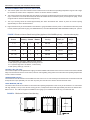
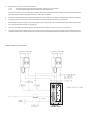
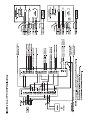
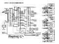
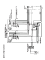
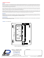
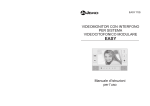
Innovations in Communications TM
since 1955
ENTERVIEWTM
VIDEO INTERCOM SYSTEM
INSTALLATION INSTRUCTIONS
VM-104 VIDEO MONITOR
HANDSET
DIRECTORY
4 INCH FLAT BRAUN TUBE
MONITOR BUTTON
CAMERA
FRAME
DOOR RELEASE BUTTON
SPEAKER
POWER ON LED
CONTRAST CONTROL
BRIGHTNESS CONTROL
CALL
BUTTONS
MICROPHONE
STAND BY SWITCH
VM-300/8T ENTRANCE PANEL
APPLICATION
The ENTERVIEWTM intercom system is a combination of an audio communication system with a video monitoring system.
This provides audio communication with the caller by the resident, as well as visual identification capability.
Audio communication is carried on by means of an amplified handset intercom system at the apartment and hands free loudspeaker
convenience at the entrance panel. Controlled entry is permitted by means of a push button actuated electric door release.
Optional equipment is available to provide additional features, including P.O. key door release and multiple monitors in the same suite.
Contact your LEE DAN® dealer for details.
PROCEDURE
1. Read installation instructions before proceeding.
3. Connect wires and install equipment.
2. Install housings and wiring.
4. Apply power and check operation.
SYSTEM COMPONENTS
MODEL
IH-357
IH-358
PS-250
PK-314A
PK-311
PK-320
PK-417
RS-075/2
VM-104
VM-300/4T
VB-004B
DESCRIPTION
Single Gang Ring for VM-104 (Mounts to drywall) or IH-358
Double Gang Box for IH-357 Ring
UL Transformer. 160 VA 16 VAC. One required per PK-314A control unit and PK-311 power supply.
Control Unit (Amplifier/Power Supply). One required per system.
Power Supply. (See system layout section for units required.)
Video distribution amplifier (4 outputs).
Dual Entrance Switcher. One required for each additional entrance panel (maximum is 3 entrances).
End-of-line Resistor. To be connected to last VM-104 on each riser run.
Video intercom monitor with amplified duplex handset.
4 Button Vandal-Resistant Entrance Camera Panel.
4 Button adder. Must be ordered with VM-300/4T for total required buttons.
800-231-1414 • 631-231-1414
155 Adams Avenue • Hauppauge, NY 11788-3699
Fax 631-231-1498 • www.LEEDAN.com
LEE DAN®
INTERCOMS • MAILBOXES • DIRECTORIES
NURSE-CALL • ANNUNCIATORS • WIRE & CABLE
With continuous product improvement, specifications are subject to change without notice.
EQUIPMENT LOCATION AND HOUSING INSTALLATION
ENTRANCE CAMERA PANEL (VM-300/4T) ENCLOSURE:
A. The entrance panel must not be located in areas of extreme heat or cold where the operating temperature range of 0-50 C might
be exceeded or where it will be subjected to moisture or adverse weather conditions.
B.
The entrance panel must be located away from direct sun exposure. Sufficient light must be provided to illuminate the caller at
night. A minimum of one 40 watt flourescent bulb should be installed above the entrance panel. (For best picture quality, source
of light should be directed to illuminate subjects face.)
C.
The top of housing should be located approximately 66" above the finished floor surface to place the camera opening
approximately 61" above the finished floor.
D.
Eight call buttons may be accomodated on the standard 1 gang VM-300/4T entrance panel. If a PO-202I Post Office lock panel
is used, minimum panel size is 2 gang. For additional buttons, consult the ENTRANCE PANEL HOUSING CHART (FIG. 1) below.
FIGURE 1 - Entrance Camera Panel Housing Chart (Applies to VAN-GUARD style only — ask about other styles)
Number of
Buttons
No. of modules
Directory Camera Button
1-8
1.
2.
3.
4.
Flush
Housing
Wall Opening
Width (A)*
Wall Opening
Height
1/2
1
1/2
BB-102
8-1/4"
10-1/4"
12 - 28
1
1
1
BB-103
12-1/4"
10-1/4"
32 - 60
1
1
1
BB-203
12-1/4"
16-1/4"
64 - 120
2
1
2
BB-205
20-1/4"
16-1/4"
124 - 136
3
1
2
BB-206
24-1/4"
16-1/4"
For postal option (PO-202I), additional panel required.
Wall opening height of BB-200 series housing is 16-1/4".
For systems larger than 136 buttons, contact factory.
Wall opening width (A)*, see FIG. 2.
CONTROL UNIT (PK-314A) :
The Control Unit (PK-314A Amplifier/Power Supply) should be installed inside the Entrance Panel. If the Control Unit must be installed
away from the Entrance Panel for some reason, observe notes regarding wiring and do not locate where the operating temperatures
of 0-40 C will be exceeded.
TRANSFORMER (PS-250) :
The transformer must be located in an accessible area near a source of 117 VAC and away from extreme heat. The transformer should
be kept at least 3' (but preferably not more than 50') away from the PK-314A. Observe all local electrical codes.
VIDEO MONITOR (VM-104) :
The video monitor must not be located in an area where the operating temperature of 0-40 C may be exceeded or in an environment
with high humidity. The top of the VM-104 housing (IH-357, IH-358) should be located approximately 66" above the finished floor.
Refer to FIG. 3 and VM-104 equipment installation notes (page 7) for installation of IH-357 ring or IH-358 back box.
FIGURE 2 - BB-Series Entrance Panel Housing
16 1/4"
16 1/4"
16 1/4"
FIGURE 3 - IH-357 & IH-358
Video Monitor Box Adapter Plate
VM-104
SYSTEM LAYOUT
A. Maximum number of VM-104 monitors per PK-314A is 50 units. Only one PK-314A control unit used per system.
B. Each additional 80 VM-104 monitors require a PK-311 control unit and PS-250 transformer. (See Figure 8 for PK-311 wiring and installation instructions.)
C. Up to three separate VM-300/4T entrance panels may be used per system, following the above guidelines for each entrance panel used. (See Figures
6 and 7 for wiring instructions.)
WIRING INSTRUCTIONS
Run wires according to WIRING LAYOUT DIAGRAM (FIG. 4) in conjunction with the following notes.
A.
Each VM-104 is supplied with a (CT-133) RG-59U connector board for RG-59U cable.
B.
The maximum number of VM-104 monitors per riser is 20. The maximum length of each riser is 200 feet.
C.
The back of VM-104 provides connecting terminals for the following. Terminals functions are as follows:
1 and 2
: Microphone for handset connects to 1,2 on PK-314A.
3 and 4
: Receiver for handset connects to 3,4 on PK-314A.
X
: Ring terminal. (Selective wire which connects to individual push button at entrance for ringing unit 1 KHz tone signal. Also detects
tone and turns monitor control circuits on for 1 minute.)
C.T.
: Control terminal. (When terminal X detects a tone, C.T. also goes high [approx. 10-12 VDC]). This system common connects to
C.T. at PK-314A which turns power on to camera via CP and CN.
+
: +17 VDC for connection to PK-314A terminal P.
: Ground for connection to PK-314A terminal N.
V
: Video Innput
G
: Video Ground
D.
E.
The CONTROL UNIT (PK-314A) provides connecting terminals with the following functions:
1 and 2
: Input from microphone of VM-104 handset. Balance input.
3 and 6
: Audio output to receiver on VM-104 handset.
M and G
: Microphone input located at entrance panel (VM-300/4T). Polarity sensitive.
Z
: 1 KHz OCS tone output for ringing monitors.
W
: Reset terminal for power supply. Shorting this terminal to - will interrupt +17 VDC for approx. 2 seconds.
S and C
: Audio output to speaker at entrance panel (VM-300/4T).
E
: Post office key lock input. Shorting to C terminal will give door strike output on L (16VAC).
L
: Door strike output 16 VAC 1 AMP.
N
: - Neg. for +17 VDC.
P
: +17 VDC output for monitors @ 3 amp maximum regulated.
T1 and T2
: 16 VAC input 160 VA
C.T.
: Control terminal common voltage coming from monitors C.T. terminal. Energizes relay for camera output voltage CP and CN.
CP
: +15 VDC output for camera. Voltage is only present when C.T. terminal has approximately 10-12 VDC.
CN
: Ground for camera voltage.
The DISTRIBUTION AMPLIFIER (PK-320) provides connecting terminals with the following functions:
A,G
: Termination resistor jumper (short if J102 is not feeding another PK-320) or (leave open if connecting to another PK-320)
J101
: Input terminal for connection from camera output.
J103
: Video output terminal for one riser.
B
: Common connection for turning system on. (Connects to PK-314A control unit terminal C.T.)
A
: Common connection for turning on PK-320. (Connects to all VM-104 monitors receiving video feed from PK320.
J102
: Video output terminal to other PK-320’s. (Comes directly from camera output.
J106, J107, J108 : Video output terminals for one riser each.
F.
Wire gauge sizes for common wires only are as follows:
+, -, CT
: Minimum 18 gauge for up to 50 monitors. Minimum 16 gauge for up to 100 monitors.
1,2,3,4
: Two twisted pair 22 gauge. Must be shielded pairs if not in metal conduit.
Intercom communication common wires must be routed away from flourescent lights and AC lines. For distances of greater than 500 feet use 20
gauge wire. Maximum distance from amplifier for communication wires is 1000 feet.
G.
Wire gauge size for selective wire (X): 22 gauge. Wire gauge size for camera wires (CP,CN): 18 gauge. Unless specified, all other wires: 22 gauge.
H.
Use 16 gauge wire to connect control unit to the transformer. If wire length is greater than 50 feet, use 14 gauge wire.
I.
For wire length of more than 100 feet, run all power supply wires (+ and -) directly to the control unit location (usually the entrance panel location).
For wire length greater than 200 feet, use 16 gauge wire.
J.
Use 2 cond., #18 cable for door release wiring. If release is located more than 50' from the control unit, use 16 gauge wire.
K.
The control unit (PK-314A) is rated for 3 amps at 17 VDC and may be used to supply power for up to 50 VM-104 (without instant-on feature). See
SYSTEM LAYOUT section for additional information. Microphone wiring must be shielded cable and the shield must be connected to terminal G.
FIGURE 4 WIRING LAYOUT DIAGRAM
PS-250
QuantumTM
Entrance Panel
WIRE CONNECTIONS AND EQUIPMENT INSTALLATION
Check all wires for shorts to each other and for grounds. Connect all wires (EXCEPT 117 VAC CONNECTIONS TO TRANSFORMERS) as shown in the
connecting diagram FIG. 5 and in accordance with the wiring instructions. Refer to FIG. 6 for dual entrance wiring.
ENTRANCE PANEL (VM-300/4T):
A. Install frame (OF-200 series) into housing (BB-200 series).
B. Connect all wires necessary as shown in connecting diagram FIGURE. 5. Refer to FIGURE. 6 for dual entrance wiring.
C. Connect coaxial video cable (RG-59U) to the camera cable connector on the back of the camera. Connect the remaining wires from the cable connector
to CN and CP to supply power.
D. Install the front panels into frame following the directions included with the directory panel.
VIDEO MONITOR (VM-104):
A. Connect all necessary wires as shown in the connecting diagram FIG. 5. Refer to FIG. 6 for dual entrance wiring. IH-357 and IH-358 housing includes
four knock-out holes for cable inlet.
B. Mount the VM-104 to the IH-357 and IH-358 ring housing using the adapter plate.
TRANSFORMER (PS-250):
A. Connect transformer 16 volt terminals to PK-314A, terminals T1 and T2. Connect transformer primary to 117 VAC observing all applicable electrical codes.
SYSTEM CHECK-OUT
Check entire system according to the operating instructions, turning each monitor on individually so that if a problem exists it may be easily identified. If the
system does not operate as indicated, refer to Trouble Shooting section.
OPERATING INSTRUCTIONS
A.
AT ENTRANCE PANEL (VM-300/4T Van-Guard ®, or QM-300/2 QuantumTM):
1. Momentarily press button corresponding to desired suite.
2. Reply in a normal voice when spoken to. Reply is hands-free.
3. When door release buzzes, enter through door.
B.
AT SUITE STATION (VM-104):
1. When call tone is heard, pick up intercom handset.
2. Adjust picture brightness and contrast as necessary using the slide control switches located just below lower right corner of video screen.
3. Identify caller on the video screen and converse with them.
4. The door may be opened by pressing the door release button marked "Door".
Each monitor stays on for approximately 1 minute when called. Picture is delayed approximately 3 to 5 seconds. When the door release is activated or when
a second caller rings another suite, the monitor will shut off.
Calls may also be initiated from the VM-104 by pressing the video monitor button marked "Monitor". This activates the camera and may be used to re- initiate
a call that has been canceled, or to monitor the entrance panel. The monitor will stay on for approximately 1 minute. Only 1 monitor at a time should be on
using video monitor button.
If standby control is switched ON, red LED will light and monitor will remain on standby, ready to operate when another call is placed from the entrance panel.
NOTE: Performance may vary with large or small installations. If no video contact with the entrance is desired or if a tenant is leaving the suite, the standby
switch may be turned OFF. Audio communication will still operate in the normal manner.
SYSTEM MAINTENANCE
ENTRANCE PANEL (VM-300/4T):
Directory panels are accessible by removing the self-tapping metal screw(s) located in the top L-channel just above each module. After removing screws,
lift L-channel away from frame. Panel can now be removed. Apply directory listings as desired and replace panels be reversing the above procedure.
CONTROL UNIT (PK-314A):
Each PK-314A has a 5 amp, 3AG fuse as an overload protection. Replace this fuse with same type and rating only. If this fuse continually opens, check
for wrong wiring or equipment failure.
TROUBLE SHOOTING
SYSTEM:
Check for 15-18 VDC on PK-314A terminals P and N. This voltage should also appear between the + and - terminals of all video monitors. NOTE: The
PK-314A has an electronic current limiter that will shut the unit off in the presence of a short circuit on the output terminals. When the short is removed, the
output should appear again. The current limiter will also act in case of an overload (too many monitors), which will cause the output to switch on and off rapidly.
This may be noticed only if all monitors are turned on.
If power supply function is satisfactory and if monitors turn on (screen lights up) but no picture is seen, the camera may be checked by connecting a monitor
directly. If the camera does not turn on check for 15 VDC on camera terminals CP and CN, then check for 10 VDC on PK-314A terminal CT (terminal N
is negative). Terminal CT voltage comes from the video distribution system (PK-320).
Problems with the video distribution system are usually due to wrong wiring. Make sure th CT terminal on each video monitor connects directly to the
distribution amplifier (PK-320) that is feeding the video signal to it. This is necessary because the PK-320 is turned on by the connection from the CT terminal
on the active monitor to PK-320 terminal 4. Terminal 3 on the PK-320 connects to PK-314A terminal CT to turn on the camera.
INTERCOM:
Wrong wiring is the cause of most intercom problems. The PK-314A may be checked by disconnecting the common wires and connecting a monitor directly
to and then checking communication. The telephone operation is independent of the video section and should operate even if the video does not. The use
of twisted pair wiring as shown on the connecting diagram FIG. 5 is essential for operation.
VIDEO MONITORS:
Video monitors are best checked by substitution. If red standby light is not illuminated when unit is turned on check if +17 VDC is present. If present replace
monitor, if not, trouble shoot wiring for +17 VDC.
FIGURE 9 - VM-104 REAR VIEW
LEE DAN®
VM-104
OVERALL DIMENSIONS: H: 8.25"; W: 7.38"; D: 2.25"
Toll-Free: 800-231-1414
Distributed by:
Phone: 631-231-1414
Fax: 631-231-1498
www.LEEDAN.com
155 Adams Avenue
Hauppauge, NY 11788-3699
With continuous product improvement, sizes and other specifications are subject to change without notice.
Printed in USA
© 1997-2002 LEE DAN® COMMUNICATIONS,