1
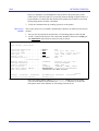
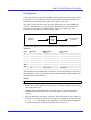
AXIS Network Print Server
Technical Reference
Serial
Parallel
Parallel
AXIS
570/670
NetWare
UNIX
OS/2
Windows
Macintosh
IBM
Lund - Boston - Tokyo - Hong Kong
The AXIS Network Print Server Technical Reference
Revision: 2.0, June 1996
© Axis Communications
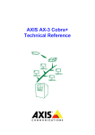
PREFACE
Thank you for purchasing an AXIS Network Print Server. Our goal in developing this
product is to enable you to connect your printers anywhere in your network, allowing
all network users access to shared printer resources.
ABOUT AXIS
Axis Communications, founded in 1984, is one of the world’s fastest growing
companies in the CD-ROM server, network print server and printer interface market.
The head quarters are located in Lund, Sweden, with subsidiaries in Boston, Tokyo,
and Hong Kong.
Axis Communications has a distributor network operating in more than 60 countries
world-wide, marketing three product lines:
Network CD-ROM Servers
Multiprotocol CD-ROM servers provide a flexible and cost-efficient solution for
sharing CD-ROMs across the network. They are available in Ethernet and Token Ring
versions, with or without a built in drive option.
Network Print Servers
These intelligent Ethernet and Token Ring print servers support a wide range of LAN
protocols. The AXIS NPS 530, 532, 550, AXIS 150, 152, AXIS 560, and 570 are
Ethernet print servers, while the AXIS NPS 630, 632, 650, AXIS 660, and 670 are
Token Ring print servers.
IBM Mainframe and S/3x – AS/400 Printer Interfaces
These products include a wide range of plug-in interfaces and free standing box
products such as the Cobra+ and the AFP IPDS-to-PostScript converter.
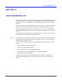
ABOUT THIS MANUAL
This manual contains a detailed technical description of the Axis print servers and how
to use them in network printing environment. If you are not familiar with the basic
functions of your Axis print server, please refer to the User’s Manual for each product
respectively.
The AXIS Network Print Server Technical Reference Revision 2.0
2
The Technical Reference is divided into four major parts:
• An introduction to networks in general, and the Ethernet and Token Ring networks
in particular - Sections 1 and 2.
• A general introduction to the Axis print server family and their internal functions Sections 3 and 4.
• How to set up and use the Axis print servers for network printing, and printing
related tasks - Sections 5 to 9.
• A description of the Axis print server parameters and how to edit them - Sections 10
and 11.
There is also a section on how to pin-point and solve problems that might occur during
the installation and operation of the Axis print server.
Every care has been taken in the preparation of this manual; if you detect any
inaccuracies or omissions, please inform us at our address - See “How To Contact
Axis” on page 280. Axis Communications AB cannot be held responsible for any
technical or typographical errors and reserves the right to make changes to the product
and manuals without prior notice.
EMISSION NOTICES
USA
This equipment generates, uses, and can radiate radio frequency energy and if not
installed and used in accordance with the instruction manual, may cause interference to
radio communications. It has been tested and found to comply with the limits for a
Class A computing device pursuant to Subpart B of Part 15 of FCC rules, which are
designed to provide reasonable protection against such interference when operated in a
commercial environment. Operation of this equipment in a residential area is likely to
cause interference in which case the user at his own expense will be required to take
whatever measures may be required to correct the interference. Shielded cables should
be used with this unit to ensure compliance with the Class A limits.
Europe
This digital equipment fulfils the requirements for radiated emission according to limit
B of EN55022/1987, and the requirements for immunity according to EN50082-1/1992
residential, commercial, and light industry. (Compliance is not valid for unshielded
network and printer cables.)
TRADEMARK ACKNOWLEDGEMENTS
AIX, Apple, AppleTalk, DEC, DOS, Ethernet, EtherTalk, Hewlett-Packard, HP, IBM,
LAN Manager, LAN Server, Lexmark, Macintosh, Microsoft, MVS, Novell, Novell
NetWare, OS/2, OS/400, PostScript, PS/2, SCO, SunOS, TokenTalk, Ultrix, Unix,
VM, VMS, VSE, Windows, are registered trademarks of the respective holders.
The AXIS Network Print Server Technical Reference Revision 2.0
3
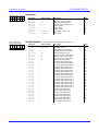
TABLE OF CONTENTS
TABLE OF CONTENTS
Section 1
INTRODUCTION TO LOCAL NETWORKS
Types of Local Networks
LAN Medium Access Techniques
Section 2
ETHERNET AND TOKEN RING NETWORKS
Ethernet Media
Ethernet Frame Formats
Token Ring Media
Token Ring Frame Formats
Repeaters
Bridges
Routers
Network Protocols
NetWare
Windows, LAN Server/LAN Manager
TCP/IP
Apple EtherTalk
System Network Architecture (SNA)
9
9
10
10
11
12
12
12
14
14
15
16
18
19
Section 3
AXIS PRINT SERVERS – INTRODUCTION
The NPS 530/630
The AXIS 150/152
The NPS 550/650
The AXIS 560/660
The AXIS 570/670
Axis Utility Software
21
21
22
22
23
24
25
Section 4
THEORY OF OPERATION
The Ethernet/Token Ring Controller
The Frame Handler
The NetWare Interface
The LAN Server/LAN Manager and Windows Interface
The TCP/IP Interface
The AppleTalk Interface
The SNA Interface
Logical Printers
26
27
27
28
29
30
31
32
34
Section 5
NETWORK PRINTING
NetWare
Windows, LAN Server/LAN Manager
Printing from IBM Hosts
TCP/IP
Printing from BSD-Type UNIX Systems
Printing from System V UNIX Systems
Printing from IBM AIX Systems
Printing from Other UNIX Systems
Printing from IBM MVS Systems
Printing from MS-DOS Systems
Apple EtherTalk
SNA
35
35
43
44
45
46
57
66
72
75
75
76
78
The AXIS Network Print Server Technical Reference Revision 2.0
7
7
8
4
TABLE OF CONTENTS
Section 6
IBM EXTENDED EMULATION MODE
The Extended Emulation Control Command
The Extended Emulation Data Format
Configuration Mode
Hex Transparency
Function Mode
User Defined Strings
String Substitutions
Bar Codes
Font Selection
85
85
86
86
88
90
91
93
95
98
Section 7
LOGICAL PRINTERS
AXIS NetPilot Logical Printer Property Page
Logical Printers - Theory of Operation
Physical Printer Port
Action at Printer Busy
Printer Information Read-Back
Character Set Conversion
Strings Before and After Print Jobs
String Substitutions
PostScript Functions
Hex Dump Mode
100
101
102
104
106
107
108
109
110
111
114
Section 8
FTP AND TELNET
Access Control
FTP Log-In
Telnet Log-In
Accounting
Status Logging
115
115
117
120
121
122
Section 9
NETWORK MANAGEMENT UNDER SNMP
System Requirements
The Axis MIB
124
124
125
Section 10
PARAMETER EDITING
NetWare, Windows and LAN Server/LAN Manager
TCP/IP
Apple EtherTalk
SNA
131
132
133
135
136
Section 11
THE PARAMETER LIST
Parameter Overview
Detailed Parameter Descriptions
137
138
149
Section 12
SOLVING PROBLEMS
Printer Communication
Network Communication
Support available on the WWW
Reporting Problems
Error Messages
231
231
233
234
235
236
The AXIS Network Print Server Technical Reference Revision 2.0
5
TABLE OF CONTENTS
APPENDIX A
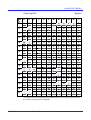
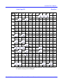
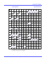
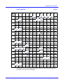
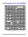
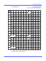
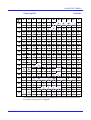
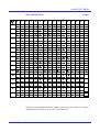
CHARACTER TABLES
237
APPENDIX B
INTERNAL PRINTOUTS
Error Messages
SNA Printing Error Messages
262
264
266
APPENDIX C
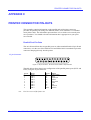
PRINTER CONNECTOR PIN-OUTS
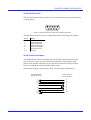
Parallel Port Pin-Outs
Parallel Ports Timing
Serial Port Pin-Outs
Serial Cable Description
271
271
272
273
273
APPENDIX D
IBM Printing Compatibility Considerations
Axis AX-3/AX-7 Cobra and Cobra+
Agile (6287 Ultra)
Andrew (Malibu)
Avatar (MainPrint CG)
I-Data (IDA 3270)
MPI (AT 02 and Rocky)
The MD-GRAPHTEXT Software
The FormsXpress Software
274
274
276
276
276
277
278
278
279
APPENDIX E
How To Contact Axis
Axis on-line service
280
280
INDEX
282
The AXIS Network Print Server Technical Reference Revision 2.0
6
INTRODUCTION TO LOCAL NETWORKS
SECTION 1
INTRODUCTION TO LOCAL NETWORKS
A local network is defined as follows:
A local network is a communications network that provides interconnection of a
variety of data communicating devices within a small area.
The need to interconnect equipment within a single building (or group of buildings) has
made local networks indispensable for business, government agencies, universities, and
other organizations.
Types of Local Networks
There are two basic types of local networks: circuit switching and packet broadcasting.
Circuit switching
The network consists of a central switch to which all devices attach. Two devices
communicate by setting up a circuit through the switch. The circuit consists of a path
and dedicated resources for transferring data between the two devices. The most
familiar example of a circuit-switching network is the private branch exchange (PBX),
used by common telephone nets.
Packet
Broadcasting
Devices share a communications network in which a transmission from any device is
heard by all other devices. Data to be transmitted are broken up into small blocks,
called packets. Packets include both user data and control information that indicate the
destination of the data. Each packet is sent onto a network and may be received by all
other devices on the network. Examples of packet broadcasting networks are Ethernet
and Token Ring.
The key to packet broadcasting is the use of a transmission medium shared by a number
of devices. An early example of this is the multi-drop line. The multi-drop line is used
for communication between one primary station (a host computer) and a number of
secondary stations (terminals and printers). For local networks, peer communication
among a number of cooperating devices is required. This type of network is referred to
as a local area network (LAN) and has the following key characteristics:
• A transmission medium is shared among the attached devices.
• Transmission is in the form of packets.
• A transmission from any station is received by all other stations hence the term
packet broadcasting.
• There is no master station – all stations cooperate to assure orderly use of the
transmission medium.
The AXIS Network Print Server Technical Reference Revision 2.0
7
INTRODUCTION TO LOCAL NETWORKS
LAN Medium Access Techniques
The two most common techniques are CSMA/CD (Carrier Sense Multiple Access with
Collision Detection) and Token Passing. The main commercial applications of these
techniques are Ethernet and Token Ring respectively.
Ethernet
The majority of installed LANs are based on Ethernet, which is a passive bus network
that utilizes CSMA/CD. The system was developed in 1976 by Metcalfe and Boggs of
Xerox. (The name Ethernet derives from the conception that space contained a
mysterious ‘ether’ medium without which light could not propagate. We now know
that this ether medium does not exist in space).
The basic function of Ethernet is quite simple:
1. If the medium is idle, transmit.
2. If the medium is busy, listen continuously until idle, then transmit immediately.
This method is very effective at light loads, but the risk of collisions (two stations
trying to transmit at the same time) increases rapidly with higher loads. This introduces
the need for the CD (collision detection) part of CSMA/CD:
3. If a collision is detected during transmission, immediately cease transmitting the
frame, and transmit a brief jamming signal to assure that all stations know that
there has been a collision.
4. Wait a random amount of time (with the mean value increasing exponentially at
each retry), then attempt to transmit again according to step 1 above.
Token Ring
Token Ring is the oldest ring control technique, originally proposed in 1969 by Olof
Söderblom. It is based on the use of a small frame (token) that circulates around the
ring when all stations are idle. This is the basic function of a Token Ring network:
1. Before a station can transmit data, it must wait until a token passes by. The station
then seizes the token and appends the fields needed to construct a frame.
2. There is now no token on the ring, so all other stations wishing to transmit must
wait.
3. The receiving station copies the data addressed to it, and generates a receipt.
4. When the frame has completed the round trip, the sending station removes the
frame and generates a free token.
5. An important implication of this technique is the inefficiency under light loads due
to the fact that a station must wait for the token before it can transmit. Under heavy
loads, however, it becomes relatively more efficient since no collisions occur.
The AXIS Network Print Server Technical Reference Revision 2.0
8
ETHERNET AND TOKEN RING NETWORKS
SECTION 2
ETHERNET AND TOKEN RING NETWORKS
This section describes the physical properties of the Ethernet and Token Ring
networks, and the different communications protocols used.
Ethernet Media
Until recently Ethernet has always been a 10 Mbit/s base band network (that’s what the
‘10base’ stands for in the descriptions below). There is now also a 100 Mbit/s Ethernet,
but since the great majority of Ethernet networks are 10 Mbit/s, the 100 Mbit/s system
is not included in this technical reference. However, there are at present three cabling
methods in use:
Thick-wire
Ethernet
(10base5)
This is the original ‘yellow cable’ Ethernet (the specifications, among many other
things actually specify the colour of the cable!). It is a thick coaxial cable (the 5 in its
name refers to the conductor spacing) to which devices are attached by mounting a
Transceiver on the cable itself, called a MAU (Media Attachment Unit). A needle
protruding from the MAU makes a connection to the inner core. The connection
between the MAU and the Ethernet device is made using a 15-pin DSUB, the interface
being known as an AUI (Attachment Unit Interface) connector. Today this type of
Ethernet is mostly used for backbones.
Thin-wire
Ethernet
(10base2)
Until not too long ago, this was the most used cabling type. It is a thin 50 ohm coaxial
cable, sometimes referred to as ‘Cheapernet’ (the 2 in its name refers to the conductor
spacing). The connection to different Ethernet devices is done using ‘T’ connectors to
tap into the network; the actual connector is a BNC type.
Twisted-pair
Ethernet
(10baseT)
Today, this is the most common cabling method for new installations. It is the cheapest
of the three cabling methods, and since the network cable does not have to pass by each
device, it is more reliable than the coaxial methods when using 10baseT. Each device
has its own cable, connected to a so-called hub, which can dynamically disconnect a
particular cable if there appears to be an error which would disrupt the entire network.
The physical connector is an RJ-45 type connector, which is similar to standard phone
plugs.
The twisted-pair cable (the T in its name refers to Twisted-pair) may be shielded (STP)
or unshielded (UTP). Shielded cables are required in Germany, and some other
countries, due to EMC (Electro Magnetic Compatibility) reasons.
The AXIS Network Print Server Technical Reference Revision 2.0
9
ETHERNET AND TOKEN RING NETWORKS
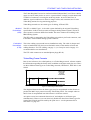
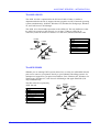
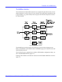
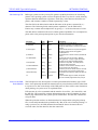
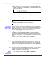
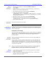
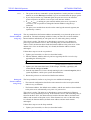
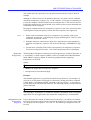
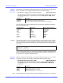
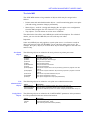
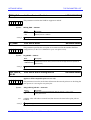
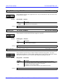
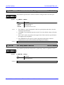
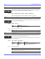
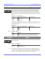
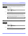
Ethernet Frame Formats
Data is sent in frames, also called packets, on an Ethernet network. A frame contains
the information regarding the frame itself, in addition to the data sent by the user. There
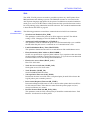
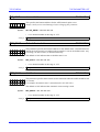
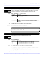
are four different frame types on Ethernet networks; Ethernet II, IEEE 802.3,
IEEE 802.3, and SNAP.
Names used
to describe
the frame
combinations
Ethernet II
Ethernet II
DIX
802.2
802.3
802.2
SNAP
SNAP
802.3
Figure 2-1 Ethernet Frame Formats
The diagram illustrates how the frame types may be encapsulated in other frames to
produce the MAC layer protocols used by LANs. For example when Ethernet II is
encapsulated in an 802.2 frame it is known as DIX.
Axis print servers have automatic detection of, and adaption to, all frame types
simultaneously. However you can selectively disable the detection of frame types for
some of the network protocols used by the print server - see the parameter list in
SECTION 11, page 137.
Ethernet Address
Each Ethernet station has a unique address consisting of 12 hexadecimal digits. The
Axis print server Ethernet address (same as the serial number) consists of two parts:
• The first 6 digits are always 00:40:8C, indicating Axis as the manufacturer.
• The remaining 6 digits are a running number unique for each Axis Ethernet print
server.
The Ethernet address is coded into the Axis print server hardware, but you may change
it to a Locally Administrated Address (LAA) as described on page 149.
Token Ring Media
Token Ring is either a 4 Mbit/s or 16 Mbit/s base band network. The units on a Token
Ring network are connected in a ring topology, meaning that the ‘last’ unit is connected
to the ‘first’ unit completing a closed loop where the token can circulate. However, the
ring topology is only signalwise and in practices not visible, since the units are
generally connected to a central MAU (Multistation Access Unit) forming a physical
star topology.
The AXIS Network Print Server Technical Reference Revision 2.0
10
ETHERNET AND TOKEN RING NETWORKS
The Token Ring MAU (not to be confused with the Ethernet MAU, see Ethernet Media
(page 9)) can be either passive or active. A passive MAU is simply a switch board with
a number of connectors accessing the small ring inside. An active MAU has, in
addition, signal conditioners to allow for longer cables, and sometimes one or more
Token Ring stations for ring monitoring purposes.
Token Ring networks use two main types of cabling, STP and UTP:
Shielded
Twisted-Pair
(STP)
The STP, or Media Type 1, is the cable system defined by the original Token Ring
specification. It allows for more units and longer cabling distances than UTP, but is
more expensive and more difficult to handle. The most common STP cabling is the
IBM Cabling System.
The STP cable is connected to the Token Ring unit with a 9-pin D-sub connector, and
to the MAU with an IBM Cabling System connector.
Unshielded
Twisted-Pair
(UTP)
This is the cabling system used in most installations today. The cable is cheaper and
easier to handle than STP, but is more limited in terms of the number of units and
cabling distances. For UTP cabling, category 3, 4, or 5 may be used. Category 5 is
recommended for new installations.
The UTP cable connectors are standard phone plugs (RJ-45).
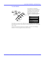
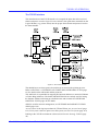
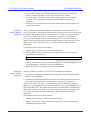
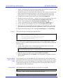
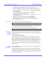
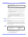
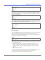
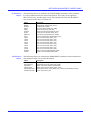
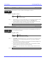
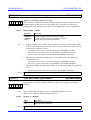
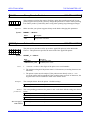
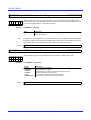
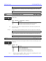
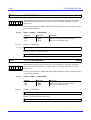
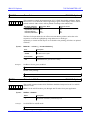
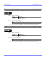
Token Ring Frame Formats
Data is sent in frames, also called packets, on a Token Ring network. A frame contains
the information regarding the frame itself, in addition to the data sent by the user. There
are three different frame types on Token Ring networks, IEEE 802.5, IEEE 802.2, and
SNAP.
Names used
to describe
the frame
combinations
802.5
802.2
802.2
SNAP
SNAP
Figure 2-2 Token RIng Frame Formats
The diagram illustrates how the frame types may be encapsulated in other frames to
produce the MAC layer protocols used by Token Ring LANs. For example when an
802.5 frame is encapsulated in an 802.2 frame it is known as 802.2.
Axis print servers have automatic detection of, and adaption to, all frame types
simultaneously. However you can selectively disable the detection of frame types for
some of the network protocols used by the print server - see the parameter list in
SECTION 11, page 137.
The AXIS Network Print Server Technical Reference Revision 2.0
11
ETHERNET AND TOKEN RING NETWORKS
Token Ring Node Address
Each Token Ring station has a unique address consisting of 12 hexadecimal digits. The
Axis print server Node address (same as the serial number) consists of two parts:
• The first 6 digits are always 00:02:31, indicating Axis as the manufacturer.
• The remaining 6 digits are a running number unique for each Axis Token Ring print
server.
The Node address is coded into the Axis print server hardware, but you may change it
to a Locally Administrated Address (LAA) as described on page 149.
Repeaters
A repeater is a signal amplifier and does not affect the logical network where it is
connected. It is used for connecting two network segments, and it can also connect
different types of Ethernet or Token Ring attachments together.
If you use 10base2, 10base5, STP or UTP media, repeaters are used if the cable length
exceeds the specified.
For 10BaseT the hubs are normally placed at reasonable distances from the network
devices, and repeaters are not used.
The use of a repeater does not require any adjustment to the Axis network print server
parameters.
Bridges
A bridge connects two segments of a network but only passing information that is
intended to travel from one segment to the other. Traffic passing between addresses
within one segment will not reach the other segment. Typically one replaces a repeater
with a bridge when it is necessary to separate network segments because of heavy load,
security, or other reasons. It can also be used for converting from Ethernet to Token
Ring, or for tunnelling one packet type into another. Typically the set-up of a bridge is
minimal - it configures itself by listening to the traffic.
The use of a bridge in an Ethernet network does not require any adjustment to the Axis
network print server parameters. For Token Ring networks, there is a parameter
controlling the source routing mode that in rare cases may need adjustment, as
described on page 151.
Routers
A router is a device for off-loading the traffic between networks. It separates two or
more logical networks (which have separate network addresses), and only passes the
traffic it is set up to pass between the networks. The main difference between bridges
and routers is that routers control the paths of the network traffic.
The AXIS Network Print Server Technical Reference Revision 2.0
12
ETHERNET AND TOKEN RING NETWORKS
There is also a device called brouter, which combines the functions of a bridge and a
router.
The Axis print servers automatically sense when the traffic is coming via a router.
However, the automatic router sensing is not a standard feature in all network
environments. If you experience problems with routed traffic, you may specify a
default router and a net mask in the Axis print server configuration.
The AXIS Network Print Server Technical Reference Revision 2.0
13
ETHERNET AND TOKEN RING NETWORKS
Network Protocols
This section provides an overview of the different protocols used for network
communications. Let’s start with a definition of the term protocol:
A protocol is a set of rules governing the communication and exchange of data between
devices in a communications system.
Communication over a network is far more complex than for example the serial
communication between a computer and a printer (where the RS-232 is a common
protocol). To make things a bit easier for us, the International Standards Organization
(ISO) has defined the OSI (Open Systems Interconnection) model, where the network
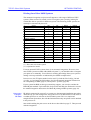
communication is divided into seven layers. The table below describes the function of
each layer:
The OSI model layers
Layer
7
Function
APPLICATION
6
PRESENTATION
5
SESSION
4
TRANSPORT
3
NETWORK
2
DATA LINK
1
PHYSICAL
Description
The top layer (i.e. closest to the user) provides services to the user
such as file server protocol and network management.
Performs transformations on data to provide a standardized
application interface and common communication services. Examples
are encryption, text compression, and reformatting.
Provides the control structure for communication between
applications; establishes, manages, and terminates connections
between cooperating applications.
Provides reliable and transparent transfer of data between end points,
end-to-end error recovery, and flow control.
Provides upper layers with independence from the data transmission
and switching technologies used to connect systems. Responsible for
establishing, maintaining, and terminating connections (X.25, layer 3).
Provides for the reliable transfer of data across the physical link, sends
blocks of data (frames) with the necessary synchronization, error
control, and flow control (HDLC, SDLC, BiSync).
Concerned with transmission of unstructured bit stream over the
physical link; involves such parameters as signal voltage swing and bit
duration; deals with mechanical, electrical, and procedural
characteristics to establish, maintain, and deactivate the physical link
(RS-232, RS-449, X.21).
NetWare
The following protocols make up the NetWare implementation of the OSI model:
The IPX Protocol
IPX (Internetwork Packet Exchange) is the NetWare network protocol. It corresponds
to the IP and UDP protocols in the TCP/IP environment (see below).
The NCP Protocol
NCP (NetWare Core Protocols) is the NetWare protocol covering the presentation,
session, and transport layers in the OSI model. The Axis print server must support NCP
in order to manage local printing using PSERVER - See “NetWare” on page 35.
The SPX Protocol
SPX (Sequenced Packet Exchange) is the normal NetWare transport layer protocol. An
Axis print server must support SPX in order to manage remote printing using
RPRINTER or NPRINTER - See “NetWare” on page 35.
The AXIS Network Print Server Technical Reference Revision 2.0
14
ETHERNET AND TOKEN RING NETWORKS
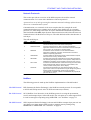
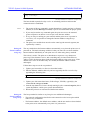
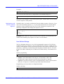
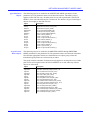
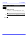
Windows, LAN Server/LAN Manager
The following protocols make up the Windows, LAN Server/LAN Manager
implementation of the OSI model:
The NetBIOS
Interface
NetBIOS (Network Basic Input/Output System) is the LAN Server/LAN Manager
session level protocol.
Applications can communicate using either sessions or datagrams. Sessions provides
reliable data transfer, while datagram communication (handled by the data link layer)
provides no guarantee of delivery.
The NetBEUI
Protocol
NetBEUI (NetBIOS Extended User Interface) is the LAN Server/LAN Manager
protocol covering the transport and network layers in the OSI model. It is optimized for
high performance in smaller LANs or LAN segments. The NetBEUI protocol is not
routable.
The LLC Protocol
LLC (Logical Link Control) is the LAN Server/LAN Manager data link layer protocol.
The Connectionless Service (IEEE 802.2 type 1) provides no guarantee of delivery,
while the Connection-oriented Service (IEEE 802.2 type 2) provides reliable data
transfer.
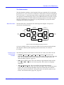
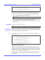
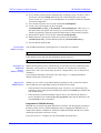
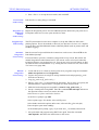
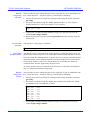
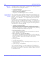
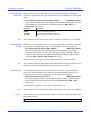
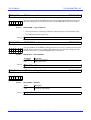
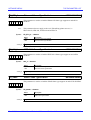
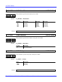
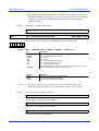
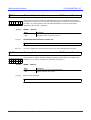
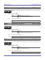
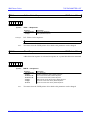
OSI Reference Model
Layer
Function
Protocol
7
Application
NDS
6
Presentation
NCP
5
Session
NetBIOS
NetBEUI
4
Transport
3
Network
2
Data Link
1
Physical
IPX
802.2
802.3
SPX
802.5
Figure 2-3 OSI model implementation in the NetWare and LAN Server/LAN Manager environments
The AXIS Network Print Server Technical Reference Revision 2.0
15
ETHERNET AND TOKEN RING NETWORKS
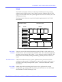
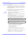
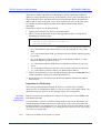
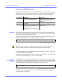
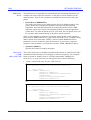
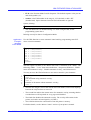
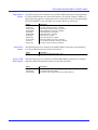
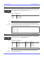
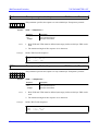
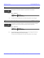
TCP/IP
The TCP/IP environment embraces a wide range of different protocols, generally
referred to as the TCP/IP protocol suite. When a system is claimed to have TCP/IP
support, this should be read as the system supports most, but not necessarily all, of the
TCP/IP protocol suite.
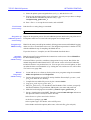
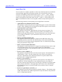
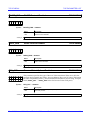
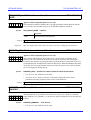
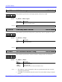
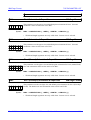
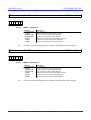
The diagram below illustrates a typical OSI model implementation in the TCP/IP
environment:
OSI Reference Model
Layer
TCP/IP Protocol Suite
Function
7
Application
6
Presentation
5
Session
4
Transport
Protocol
Telnet
FTP
LPD
SNMP
TCP
Others
UDP
ICMP
3
Network
2
Data Link
1
Physical
IP
Ethernet
ARP
Token Ring
Other Media
Figure 2-4 OSI model implementation in the TCP/IP environment
The Telnet
Protocol
The FTP Protocol
The SNMP
Protocol
Telnet is a protocol for terminal emulation (typically VT100 or 3270 traffic) over a
TCP/IP network. It does not handle the emulation itself – this is done by the application
program (on most systems called ‘telnet’ – just to add to the general confusion!). The
telnet protocol also includes printing functionality, generally referred to as Reverse
Telnet.
FTP (File Transfer Protocol) is a generic application level protocol used for file
exchange over the network. It is designed to run in interactive mode, is fairly easy to
use, and it is part of any existing TCP/IP system - or at least all those that we have
encountered.
SNMP (Simple Network Management Protocol) is an application for network
management, e.g. verifying traffic and planning of traffic load. See also NETWORK
MANAGEMENT UNDER SNMP (page 124).
The AXIS Network Print Server Technical Reference Revision 2.0
16
ETHERNET AND TOKEN RING NETWORKS
The LPD Protocol
The BOOTP
Protocol
The PROS
Protocol
LPD (Line Printer Daemon) is an application level protocol used for remote printing.
Its primary use is to send print data from one host to another. Two applications using
LPD are lpr and lpq.
BOOTP (Bootstrap Protocol) is an application level protocol used for reading operating
environment parameters (such as the Internet address) at power-up.
PROS (Patrik & Ricard Operating System) is an Axis proprietary application level
protocol, more printer oriented than the standard TCP/IP applications. In particular, it
supports bi-directional printing, featuring automatic logging of printer status and
feedback. PROS uses the TCP protocol for transport, which it accesses via Sockets
(Berkeley networking support).
The UNIX systems supported by Axis print servers are shown by the table on page 72
The PROS source code can be up-loaded from the Axis print server via ftp.
The TCP Protocol
TCP (Transmission Control Protocol) is the most important transport level protocol,
used by the Telnet and FTP application protocols. It is more advanced than UDP (see
below), in particular, it has end-to-end error recovery that ensures that data safely
arrives at the destination.
The UDP Protocol
UDP (User Datagram Protocol) is the other transport level protocol, used by Axis print
servers for SNMP and BOOTP only. Unlike TCP, UDP does not provide end-to-end
error recovery, and is therefore not classified as a reliable protocol. In practice, UDP
works fine for small networks, while the increased need for error recovery makes TCP
necessary in larger networks.
The IP Protocol
IP (Internet Protocol) represents the network layer in the OSI model. It is primarily
responsible for connecting devices over the network using the Internet Address.
The ICMP
Protocol
ICMP (Internet Control Message Protocol) cooperates with IP in the network layer to
control multiple network routing and similar tasks. It manifests itself to the user in the
form of the ping command, which is used to check IP communication.
The ARP Protocol
ARP (Address Resolution Protocol) is a low level transport layer protocol. Its purpose
is to map IP (Internet) to Ethernet addresses.
The RARP
Protocol
RARP (Reverse Address Resolution Protocol) is a low level transport layer protocol.
Its purpose is to read the Internet address at power-up.
The AXIS Network Print Server Technical Reference Revision 2.0
17
ETHERNET AND TOKEN RING NETWORKS
Apple EtherTalk
The following protocols make up the Apple EtherTalk implementation of the OSI
model:
The PAP Protocol
PAP (Printer Access Protocol) is an application layer protocol for print data
management. It compares to LPD in the TCP/IP protocol suite.
The ATP Protocol
ATP (AppleTalk Transaction Protocol) is a session and transport layer protocol,
corresponding to TCP in the TCP/IP protocol suite.
The DDP Protocol
DDP (Datagram Delivery Protocol) is a network layer protocol, comparable to IP in the
TCP/IP protocol suite.
The RTMP
Protocol
RTMP (Routing Table Maintenance Protocol) is a network layer protocol responsible
for routing information management. Together with ZIP and AEP (see below), it makes
up the Apple equivalent to ICMP in the TCP/IP protocol suite.
The ZIP Protocol
ZIP (Zone Information Protocol), is a protocol that handles the AppleTalk Zone
function. A zone is a segment of users forming a sub net of the Ethernet network. Zone
management is primarily used to organize long lists of entities.
The AEP Protocol
AEP (Apple Echo Protocol) is a protocol for verifying communication, similar to ping
in the TCP/IP suite ICMP protocol.
The AARP
Protocol
AARP (AppleTalk Address Resolution Protocol) is a network layer protocol
performing the same functions as ARP in the TCP/IP protocol suite.
The AXIS Network Print Server Technical Reference Revision 2.0
18
ETHERNET AND TOKEN RING NETWORKS
System Network Architecture (SNA)
Introduction
The SNA support enables printing from mainframes and mini computers using native
protocols and data streams. All protocol and data stream conversion is made in the Axis
570/670 print server, resulting in higher performance, reliability, and better control.
The host will see the Axis 570/670 as a LAN-attached control unit, as will be described
in more detail.
Nomenclature
and shortforms
• SNA: Systems Network Architecture
• LU: Logical Unit
• PU: Physical Unit
• NAU: Network Accessible Unit (PU or LU)
• LU-x: LU type x
• LU #x: LU address
Node type will be used instead of PU type, as a T2.1 node does not contain a PU.
SNA Protocols
SNA is really a set of different protocols, where each set is distinguished through PU
(node) types, and LU types. Different devices use different types of SNA. SNA can be
roughly mapped to the OSI model, but as SNA was designed before OSI, there is no
one-to-one mapping.
Layer
Function
1
Transaction Services
Provides application services such as distributed
database access and document interchange.
2
Presentation Services
Formats data for different presentation media and
coordinates the sharing of resources.
3
Data Flow Control
Synchronizes data flow, correlates exchanges of
data, and groups related data into units.
4
Transmission Control
Paces data exchanges to match processing
capacity and enciphers data if security is needed.
5
Path Control
Routes data between source and destination and
controls data traffic in the network.
6
Data Link Control
7
Physical Control
Transmits data between adjacent nodes.
Connects adjacent nodes physically and
electrically.
Figure 2-5 The SNA implementation
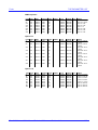
When discussing SNA it is easier and more appropriate to talk about node and LU
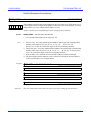
types. The following tables show the different node and LU types within SNA. Bold
type indicate the SNA protocols supported by Axis 570/670 products.
The AXIS Network Print Server Technical Reference Revision 2.0
19
ETHERNET AND TOKEN RING NETWORKS
SNA Node Types
The following node types are defined in SNA:
Node type 1 (PU-1)
Used by 5250 terminal controllers like the IBM 5294 and IBM 5394. LU types 4
and 7 can be used with PU-1.
Node type 2.0 (PU-2)
Used by 3270 cluster controllers like the IBM 3274 and the IBM 3174. LU
types 1, 2, 3, and 6.2 (dependent) can be used with PU-2.
Node type 2.1 (T2.1)
Used by PCs, workstations, intelligent controllers, etc. Serves as a base for
APPN (Advanced Peer-to-Peer Networking). LU type 6.2 (independent) can be
used with T2.1.
Node type 4 (PU-4)
Used by communications controllers like the 3745. Can handle any defined LU
type.
Node type 5 (PU-5)
Used by host nodes (mainframes). Can handle any defined LU type.
T2.1 is available in different flavours: Low-Entry Networking Node (LEN node), End
Node (EN) and Network Node (NN). APPN is IBM’s follow-up to SNA. The main
difference between APPN and traditional sub-area type SNA is that all nodes are equal
(peer-to-peer network) and traditional SNA is hierarchical in nature: PU-5 and PU-4
devices control all other devices in the network. APPN has the same purpose as
TCP/IP, but is in no way compatible.
The node types typically implemented by peripheral devices are either PU-1, PU-2 or
T2.1. PU-1 must be encapsulated in T2.1/LU-6.2 to be transported over a LAN. PU-2
and T2.1 are typically transported over IEEE 802.2 LLC, in the case of LANs.
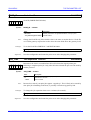
SNA LU Types
The following LU types are defined in SNA:
LU type 1 (LU-1)
Used by 3270 printers supporting the SCS and IPDS data streams
LU type 2 (LU-2)
Used by 3270 terminals
LU type 3 (LU-3)
Used by 3270 printers supporting the 3270 data stream
LU type 4 (LU-4)
Used by 5250 printers supporting the SCS or IPDS data streams
LU type 6.2 (LU-6.2)
Used by host nodes (including AS/400), PCs, workstations, as well as other
devices (including some IPDS printers).
LU type 7 (LU-7)
Used by 5250 terminals
Note that all printers used with mainframes today support both LU-1 and LU-3, with or
without support for IPDS.
The AXIS Network Print Server Technical Reference Revision 2.0
20
AXIS PRINT SERVERS – INTRODUCTION
SECTION 3
AXIS PRINT SERVERS – INTRODUCTION
This section gives a brief overview of the Axis network print server family. If you are
unfamiliar with your Axis print server and its functions, we recommend that you also
browse through the User’s Manual to get a general idea of its functions.
The Axis network print servers are multi-protocol stand-alone network print servers for
the Ethernet or Token Ring environment. Depending on model, the protocol support is
different, see below. A common feature however is the simultaneous handling of all the
supported protocols. Axis print servers make it possible to connect your printers
anywhere in an Ethernet or Token Ring network, allowing all network users access to
shared printer resources.
Because of their powerful built-in features they are extremely user-friendly to install
and use.
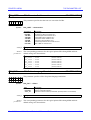
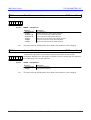
The NPS 530/630
The NPS 530/630 are pocket-sized plug-in network print servers for the Ethernet and
Token Ring networks respectively, that plugs directly info the printers parallel
(Centronics) port. The NPS 530 connection is via a twisted pair (10baseT), while the
NPS 532 uses a thin wire (10base2) cable. Otherwise the NPS 530 and the NPS 532 are
functionally equivalent.
The NPS 630 connects to the network via an UTP (Media Type 3) Token Ring cable
and NPS 632 via an STP (Media Type 1) Token Ring cable.
The supported network environments are
NetWare, LAN Server/LAN Manager,
Windows, TCP/IP, and Apple EtherTalk
(NPS 530 only). For NPS 530, TCP/IP
and Apple EtherTalk are available as
upgrades (software keys) from your
dealer.
Parallel
AXIS
530/630
NetWare
UNIX
NPS 530/630
NetWare
NetBIOS/NetBEUI
TCP/IP
Apple EtherTalk (NPS 530 only)
IBM SNA
Logical Printers
Parallel Printer Ports
Serial Printer Ports
OS/2
x
x
x
x
Windows
Macintosh
x
1
0
The AXIS Network Print Server Technical Reference Revision 2.0
21
AXIS PRINT SERVERS – INTRODUCTION
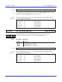
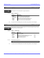
The AXIS 150/152
The AXIS 150/152 is optimized for the PC based LANs of today’s smaller or
departmentalized networks. It supports the most popular versions of network operating
systems simultaneously: NetWare, Windows NT, Windows for Workgroups, Windows
95, and LAN Server/LAN Manager.
The AXIS 152 is functionally equivalent to the AXIS 150. The only difference is that
the AXIS 150 connects to the network via a 10 base T Ethernet cable (RJ-45
connector), while the AXIS 152 connects via a thin wire (10base2) Ethernet cable.
AXIS 150/152
NetWare
NetBIOS/NetBEUI
TCP/IP
Apple EtherTalk
IBM SNA
Logical Printers
Parallel Printer Ports
Serial Printer Ports
Parallel
Parallel
AXIS 150
x
x
2
0
NetWare
OS/2
Windows
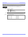
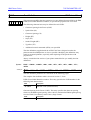
The NPS 550/650
Whether you are running UNIX systems, Macs, PCs or OS/2s, the AXIS NPS 550/650
print server connects your printers directly to your Ethernet/Token Ring network. Its
multiprotocol support lets you print from NetWare, Unix, Windows NT, Windows for
Workgroups, Windows 95, LAN Server/LAN Manager and Apple EtherTalk (550
only) simultaneously.
The NPS 550/650 is replaced by
AXIS 560/660.
Serial
Parallel
Parallel
NPS 550/650
NetWare
NetBIOS/NetBEUI
TCP/IP
Apple EtherTalk (NPS 550 only)
IBM SNA
Logical Printers
Parallel Printer Ports
Serial Printer Ports
x
x
x
x
AXIS
550/650
NetWare
x
UNIX
2
1
OS/2
Windows
Macintosh
The AXIS Network Print Server Technical Reference Revision 2.0
22
AXIS PRINT SERVERS – INTRODUCTION
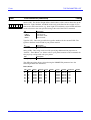
The AXIS 560/660
Serial
Parallel
Parallel
AXIS
560/660
NetWare
The AXIS 560 is a stand alone
network print server for the Ethernet
environment. It has two high-speed
parallel printer ports and one serial
printer port, and connects to the
network via a twisted-pair (10baseT)
or a thin-wire (10base2) Ethernet
cable.
UNIX
OS/2
Windows
Macintosh
AXIS 560/660
NetWare
NetBIOS/NetBEUI
TCP/IP
Apple EtherTalk (Axis 560 only)
IBM SNA
Logical Printers
Parallel Printer Ports
Serial Printer Ports
x
x
x
x
x
2
1
The AXIS 660 is identical to the AXIS 560 except it is designed for the Token Ring
environment and connects to the network via an STP (Media Type 1) or a UTP (Media
Type 3) cable.
The supported network environments are NetWare, LAN Server/ LAN Manager,
Windows, TCP/IP and Apple EtherTalk (AXIS 560 only).
The AXIS Network Print Server Technical Reference Revision 2.0
23
AXIS PRINT SERVERS – INTRODUCTION
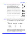
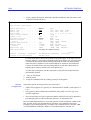
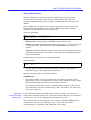
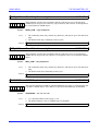
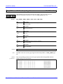
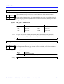
The AXIS 570/670
The AXIS 570 is a stand alone network print server for the Ethernet environment. It has
two high speed parallel printer ports and one serial port, and connects to the network
via a twisted pair (10baseT), or a thin wire (10base2) Ethernet cable.
The AXIS 670 is functionally equivalent to the AXIS 570 but is designed for the Token
Ring environment. Connection to the network is via an STP (Media Type 1) or a UTP
(Media Type 3) cable.
The supported network environments are IBM Mainframe, AS/400, NetWare,
LAN Server/ LAN Manager, Windows, TCP/IP, and Apple EtherTalk (AXIS 570
only). This means that users connected to a mainframe or AS/400 can share a printer
with LAN connected users.
The SNA support enables printing
from mainframes and mini
computers using native protocols and
data streams. All protocol and data
stream conversion is made in the
AXIS 570/670 print server, resulting
in higher performance, reliability,
and better control. The host will see
the AXIS 570/670 as a
LAN-attached control unit, as will be
described in more detail in the
following chapters.
Serial
Parallel
Parallel
AXIS
570/670
NetWare
UNIX
OS/2
Windows
Macintosh
AXIS 570/670
NetWare
NetBIOS/NetBEUI
TCP/IP
Apple EtherTalk (Axis 570 only)
IBM SNA
Logical Printers
Parallel Printer Ports
Serial Printer Ports
IBM
x
x
x
x
x
x
2
1
The AXIS Network Print Server Technical Reference Revision 2.0
24
AXIS PRINT SERVERS – INTRODUCTION
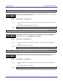
Axis Utility Software
Installation of the Axis network print servers and their integration into the network is
done using the Axis software; AXIS NetPilot, AXIS Print Utility for Windows, AXIS
Print Utility for OS/2, AXIS Installer for NetWare for and axinstall for Unix
environments.
AXIS NetPilot
AXIS Print Utility
for Windows
or OS/2
The AXIS NetPilot software
supplied with the Axis print servers
makes the job of installation and
configuration quick and convenient.
AXIS NetPilot runs on Windows
platforms and provides an
installation Wizard so that the print
servers are rapidly put to use. It also provides user friendly facilities to tune the
configuration.
The Axis Print Utility for Windows or OS/2
are dual purpose applications for network
printing in a Windows or OS/2 environment.
The functions performed are:
• Install and maintain Axis Print Server
printer ports as Windows/OS/2 printer
ports.
• Capture and monitor print jobs directed to Axis Print Servers
Axis Print Utility can run in both Peer-to-Peer and Client-Server mode.
axinstall for Unix
Installation of an Axis Print Server from a Unix workstation is carried out using the
auto installation script axinstall which is resident in the print server. The installation
procedure simply involves fetching the axinstall script using FTP and then executing
the script; the script guides you step by step through the installation.
More than 20 different Unix variants are supported by axinstall. If the Unix system is
not recognized a generic system is proposed.
AXCFG Print
Server
Configuration
Utility
This utility is supplied with the NPS series. It is a menu-driven package that fetches the
parameter values held in the print server, and then allows you to edit and download
them. It will run under DOS or Windows on a PC.
Axis Installer
for NetWare
This allows you to install the AXIS 150/152 into the NetWare environment - it runs
under Windows with a NetWare client installed. It allows you to configure NetWare by
adding new print queues and connecting them to one of the printers attached to the
AXIS 150/152 print server.
The AXIS Network Print Server Technical Reference Revision 2.0
25
THEORY OF OPERATION
SECTION 4
THEORY OF OPERATION
This section contains a technical description of the internal structure of the Axis
Network Print Servers, and the basic data and control flow. It is not necessary to read
this in order to use the print server functions and features (they are all described from
the user’s point of view in the following sections), but the information given here
should serve as a guide to understanding the relations and interactions between the
different functions within the print server.
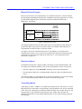
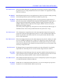
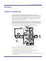
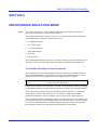
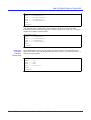
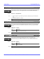
The block diagram below is a general schematic overview of the Axis print servers,
from the network attachment on the left to the printers on the right. This diagram may
include functions that are not present in your print server. You should consult your data
sheet or user’s manual to ascertain which functions are present in your print server.
The individual operations will be shown in more detail later in this section.
Figure 4-1 The Axis Network Print Server – a schematic overview
The following conventions apply to all diagrams in this section:
• The data flow is bi-directional unless otherwise indicated.
• Most of the control inputs are parameters (e.g. ‘NetWare protocol enable’
NETW_ENB enables or disables the NetWare Interface).
• Switches indicate the possibility to select a function block via the parameters held in
the config file.
The AXIS Network Print Server Technical Reference Revision 2.0
26
THEORY OF OPERATION
Note:
There is no logical printer support in NetWare for the NDS compatible series of print
servers, e.g. AXIS 560/660 and AXIS 570/670.
The Ethernet/Token Ring Controller
The Ethernet/Token Ring controller handles the receiving and transmitting of frames
on the Ethernet or Token Ring media. Together with the Frame Handler, it represents
the two lowest layers (the physical layer and the data link layer) of the OSI model. It is
controlled by the Node Address parameter (NODE_ADDR.) and in the case of Token
Ring print servers also by the Source Routing Mode parameter (S_ROUTE.).
The Frame Handler
The frame handler is responsible for passing frames (data packets) between the
Ethernet or Token Ring controller and the protocol interfaces. The actions of the frame
handler require no special considerations since the detection, transmission, and
encapsulation of frames is fully automatic. However it is possible to switch off the print
server’s response to one or more frame types by altering the appropriate parameters, for
example see the NetWare frame type parameters on page 167.
There are special conditions under which you may wish to disable the print servers
response to particular frame types. For example if your network has multiple sections
with different frame types on some of the sections, then it could happen that the print
server will log onto the wrong network section and adapt to a frame type not
compatible with the intended network section.
The AXIS Network Print Server Technical Reference Revision 2.0
27
THEORY OF OPERATION
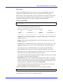
The NetWare Interface
The main function of the NetWare interface is to unpack the print data in the received
frames and pass it on to the Logical Printers block. It also packs data returned from the
Logical Printers (e.g. printer status) into the proper frame format and passes it back to
the frame handler.
Figure 4-2 The NetWare Interface
The shaded boxes are those protocols not directly involved in the printing process.
Refer to ETHERNET AND TOKEN RING NETWORKS (page 9) for details on the OSI
model and the protocols.
The NetPilot Interface communicates with the AXIS NetPilot configuration utility, see
also PARAMETER EDITING (page 131).
Printing in the NetWare environment is discussed in NETWORK PRINTING: NetWare
(page 35).
The AXIS Network Print Server Technical Reference Revision 2.0
28
THEORY OF OPERATION
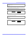
The LAN Server/LAN Manager and Windows Interface
The main function of the LAN Server/LAN Manager interface is to unpack the print
data in the received frames and pass it on to the Logical Printers block. It also packs
data returned from the Logical Printers (e.g. printer status) into the proper frame format
and passes it back to the frame handler.
Figure 4-3 The LAN Server/LAN Manager Interface
The shaded boxes are those protocols not directly involved in the printing process.
Refer to ETHERNET AND TOKEN RING NETWORKS (page 9) for details on the OSI
model and the protocols.
The NetPilot Interface communicates with the AXIS NetPilot configuration utility, see
also PARAMETER EDITING (page 131).
Printing in the LAN Server/LAN Manager environment is discussed in NETWORK
PRINTING: Windows, LAN Server/LAN Manager (page 43).
The AXIS Network Print Server Technical Reference Revision 2.0
29
THEORY OF OPERATION
The TCP/IP Interface
The main function of the TCP/IP interface is to unpack the print data in the received
frames and pass it on to the Logical Printers block. It also packs data returned from the
Logical Printers (e.g. printer status) into the proper frame format and passes it back to
the frame handler.
Figure 4-4 The TCP/IP Interface
The shaded boxes are those protocols not directly involved in the printing process.
Refer to SECTION 2 - ETHERNET AND TOKEN RING NETWORKS: TCP/IP (page
16) for details on the OSI model and the protocols.
The ARP block is responsible for mapping IP (Internet) addresses to network (Ethernet
or Token Ring) addresses. The RARP and BOOTP blocks are mainly used for setting
the Internet Address and setting up a default router and net mask. See NETWORK
PRINTING: TCP/IP (page 45) for details.
SNMP is used for network management, see NETWORK MANAGEMENT UNDER
SNMP (page 124).
Access Control is the log-in procedure for FTP and Telnet, see Access Control (page
115). File System is the Axis print server file system, see The File System (page 119).
Printing in the TCP/IP environment is discussed in Network Printing: TCP/IP (page
45).
The AXIS Network Print Server Technical Reference Revision 2.0
30
THEORY OF OPERATION
The AppleTalk Interface
The main function of the AppleTalk interface is to unpack the print data in the received
frames and pass it on to the Logical Printers block. It also packs data returned from the
Logical Printers (e.g. printer status and printer reverse data) into the proper frame
format and passes it back to the frame handler.
Figure 4-5 The AppleTalk Interface
Refer to Ethernet and Token Ring Networks: Apple EtherTalk (page 18) for details on
the OSI model and the protocols.
The Printer/Spooler Driver is the interface to the Apple Macintosh printing
environment, see Network Printing: Apple EtherTalk (page 76). The shaded boxes are
those protocols not directly involved in the printing process.
Printing in the Apple EtherTalk environment is discussed in Network Printing: Apple
EtherTalk (page 76).
The AXIS Network Print Server Technical Reference Revision 2.0
31
THEORY OF OPERATION
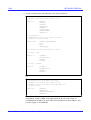
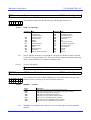
The SNA Interface
The SNA Interface emulates a LAN attached 3270-type controller (PU-2) with eight
logical units, LU1–LU8. The LUs are defined as 3270 printers. Print jobs complying to
LU-1 SCS and LU-3 3270 data stream will be accepted and converted to the selected
ASCII printer command language (PCL5, PCL4, IBM Proprinter, Epson FX or Epson
LQ), before being sent to a certain AXIS 570/670 physical port. The AXIS 570/670
also has a USER printer driver that gives you the possibility to specify the ASCII
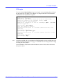
commands to be sent to your printer.
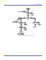
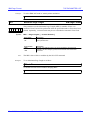
Data Flow Chart
The basic data flow is illustrated in the following block diagram. The protocol
conversion is described below.
LU-1/SCS
Control Codes
PU
NAU0
Frame
Handler
PathControl
(PU type 2.0) NAU1-8
LU-1/SCS
data
EBCDIC
to Axis
internal code
Axis Internal
Char. Codes
Printer
Control Sequences
Axis
internal code
to ASCII
Printer
Driver
String
Substitution
LU
LU-3/DSE
data
LU-1/SCS
Emulation
DBC
to Axis
internal code
LU-3/DSE
Control Codes
Logical
Printers
Extended
Emulation
LU-3/DSE
Emulation
Printer
Control Sequences
Figure 4-6 AXIS 570/670 IBM SNA interface Flow Chart
As soon as a buffer of data is received, the AXIS 570/670 starts processing the data.
The data takes different paths depending on the current mode, LU-1/SCS or
LU-3/DSE.
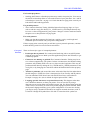
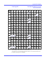
Character and
Control Code
Formats
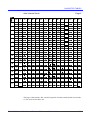
The following Character and Control Code formats are used by the AXIS 570/670:
• EBCDIC (Extended Binary Coded Decimal Interchange Code): This is the
character representation format used by LU-1/SCS mode. The codes are in the range
$40 - $FE, and depend on the System Language used by the IBM system. See
character tables, page 238 - page 253.
• DBC (Device Buffer Code): This is the character representation format used by
LU-3/DSE mode. The codes are in the range $08 - $BF, and are not language
dependent.
• AIC (Axis Internal Code): This is the AXIS 570/670 internal character
representation format. The codes are in the range $0000 - 02FF (divided into three
pages), and are not language dependent. Page one contains the most common
characters, where the codes $20 - $FF equals the PC 850 ASCII symbol set (see
below). See character tables, page 254 - page 256.
The AXIS Network Print Server Technical Reference Revision 2.0
32
THEORY OF OPERATION
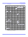
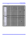
• ASCII (American Standard Code for Information Interchange): This is the
character representation format used by standard printers. The codes are in the range
$20 - $FF, and depend on the Symbol Set used by the printer. The AXIS 570/670
supports 5 pre-defined symbol sets: PC 850, Roman 8, PC 437, ECMA-94
(Latin-1), and US ASCII.
Control Codes are in the range $00 - $1F, and do not depend on the symbol set. The
codes used by AXIS 570/670 are $0A (Line Feed), $0C (Form Feed), $0D (Carriage
Return), and $1B (the Escape Character). See character tables, page 257 - page 261.
LU-1/SCS Data
Processing
The data is separated into SCS Control Codes ($00 - $3F), and EBCDIC Character
Codes ($40 - $FE).
The control codes are passed through the LU-1/SCS Emulation, which translates them
into printer control sequences.
The EBCDIC character codes are translated into Axis Internal Code (AIC) by the
EBCDIC to Axis Internal Code block for further processing. This block also performs
the basic page formatting – line breaks are inserted according to the Maximum Print
Position (MPP), and page breaks are inserted according to the Maximum Page Length
(MPL).
LU-3/DSE Data
Processing
The data is separated into LU-3/DSE Control Codes ($00 - $07), and DBC Character
Codes ($08 - $BF).
The control codes are passed through the LU-3/DSE Emulation, which translates them
into printer control sequences.
The DBC character codes are translated into Axis Internal Code (AIC) by the DBC to
Axis Internal Code block for further processing. This block also performs the basic
page formatting – line breaks are inserted according to the Maximum Print Position
(MPP), and page breaks are inserted according to the Maximum Page Length (MPL).
String
Substitutions
The String Substitution function searches the data stream for specified sequences of
characters, and replaces them with other sequences. See “String Substitutions” on
page 93.
Axis Internal
Code to ASCII
Character
Translation
This block translates the Axis Internal Code character codes to ASCII character codes
according to the current symbol set.
Extended
Emulation
The Extended Emulation block processes all non-IBM function references in the data
stream, such as Hex Transparency, Configuration Commands, and Function Calls. See
“The Extended Emulation Control Command” on page 85.
Printer Driver
The Printer Driver transfers the data to the logical printer.
The AXIS Network Print Server Technical Reference Revision 2.0
33
THEORY OF OPERATION
Logical Printers
For details of how the Logical printer function operates refer to SECTION 7 LOGICAL PRINTERS (page 100)
The AXIS Network Print Server Technical Reference Revision 2.0
34
NETWORK PRINTING
SECTION 5
NETWORK PRINTING
This section covers topics concerning network printing in general, and printing using
the Axis print servers in particular. It is organized according to each of the network
protocols as follows:
• NetWare
• Windows, LAN Server/LAN Manager
• TCP/IP
• Apple EtherTalk
• SNA
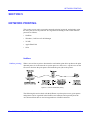
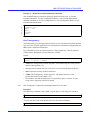
NetWare
NetWare printing
When a user wishes to print a document the workstation print driver produces the print
data and passes it via the network to a print queue on a file server. A print server on the
file server monitors the print queues and sends the print jobs to the printer:
Figure 5-1 Overview of NetWare printing
The following discussion deals with the different ways that print servers, print queues
and printers can be organized in the NetWare environment, and especially how the
Axis Network Print Server can be integrated into a NetWare network.
The AXIS Network Print Server Technical Reference Revision 2.0
35
NETWORK PRINTING
Printer location
The location of the printer is an important issue because it influences the efficiency of
both the network and the people using the network. For example if a busy printer is
connected to a workstation it will slow down the operation of the workstation because
of the time taken to service the printer.
In a NetWare environment the printers may be located as follows:
A Local Printer connected to a
File Server (or workstation) that
is running NetWare PSERVER
software.
A Remote Printer connected to
a workstation that is running
either NetWare’s NPRINTER
or RPRINTER software.
A Network Printer connected
through a network print server.
The use of an Axis network
print server will release work
load from NetWare File Servers
and/or Workstations, and at the
same time allow the convenient
siting of printers anywhere on
the NetWare network.
Figure 5-2 Printer locations in a NetWare Environment
The AXIS Network Print Server Technical Reference Revision 2.0
36
NETWORK PRINTING
Print Servers and
Print queues
In the simplest setup each print queue on the network has a single
printer connected to it. The illustration shows that the printers
connected to LPT1 and LPT2 are connected to two separate
queues, A and B. This is the way that printer ports and queues are
represented in the NetPilot Modify NetWare window.
But if a printer is found to be overloaded with print jobs it is
possible to connect two or more printers to the same queue. The
print server then selects the next available printer for each print
job in the queue.
On the other hand if a printer is under-used, it is possible to have
multiple print queues connected to it. Each queue may be given a
different level of priority so that the print server will search the
queues for print jobs from the highest priority queue down to the
lowest priority queue.
The print server can send jobs to multiple printers at the same time
as servicing multiple queues. The illustration on the right shows
both queue A and B connected to the printers on LPT1 and LPT2.
The Axis network print servers can be configured to work in any
of these ways except that queue priorities are not supported.
NDS & Non-NDS
Axis Network
Print Servers
Figure 5-3 Print queue
to printer relationships
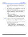
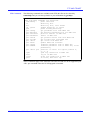
Since the introduction of NetWare 4.x, Axis print servers have been designed to
operate within NetWare’s Network Directory Services (NDS). But those print servers
designed before the release of NetWare 4.x cannot use NDS facilities unless they have
had their firmware updated.
If you want to take advantage of the superior facilities of NDS, you should firstly
determine whether your print server is NDS compatible or not.
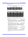
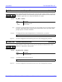
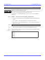
This is the NDS compatibility situation at the time of publishing this technical
reference:
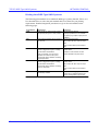
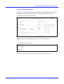
Print Server Model
Firmware Version
NDS Compatible?
AXIS 150/152
4.25
No
NPS 530/532
5.02
No
NPS 630/632
5.02
No
NPS 550/650
5.02
No
AXIS 560/660
5.10
Yes
AXIS 570/670
5.14
Yes
Axis has a policy of continuous advancement of the print server firmware, and as such
work is being done to produce firmware updates for NDS compatibility. However this
may not be possible for all of the older models. Your dealer will be able to advise you if
there has been a firmware update produced for your print server, or you can check the
Axis on-line service, see APPENDIX E Axis on-line service (page 280).
The AXIS Network Print Server Technical Reference Revision 2.0
37
NETWORK PRINTING
Because of the introduction of new versions of NetWare it is inevitable that there are
differences in the print server configuration procedures. However by using AXIS
NetPilot configuration software, these differences are easy to handle because of the
software’s ability to detect which version of NetWare is being used and which type of
print server is being configured.
If your print server is not NDS compatible you can use it with NetWare 4.x by using
the bindery emulation provided within NetWare 4.x. See “Login method for
‘Non-NDS’ Axis Print Servers on NetWare 4.x” on page 40.
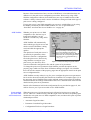
AXIS NetPilot
Whether your print server is NDS
compatible or not, the best way to
install and configure it on all
NetWare versions is by using AXIS
NetPilot.
AXIS NetPilot will automatically
detect which type of print server and
which version of NetWare is being
used, and offer the appropriate
options.
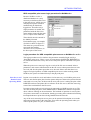
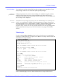
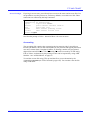
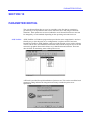
When you Enabling or Disabling the print
server in the NetWare environment by
clicking on this box and clicking OK, NetPilot
will then alter the corresponding parameter
in the print server’s configuration file, e.g.
NETW_ENB. : YES
The operation of each print server is
governed by its parameter values
which are stored in a configuration
file in the print server. However by
using NetPilot to configure your
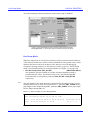
Figure 5-4 Parameter editing using AXIS NetPilot
print server you don’t have to be
concerned about the configuration file, and the syntax of its parameters.
To change the print server parameters with NetPilot you alter the options on the
property pages which are in the form of Windows dialogs (see figure 5-4). NetPilot
then converts the contents of the property pages into the appropriate entries in the print
server configuration file.
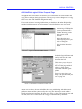
AXIS NetPilot not only makes it easy for you to configure the print server parameters
but it can also be used to modify the Network environments. For example, figure 5-5 on
the next page, shows NetPilot being used to add and connect print queues in NetWare.
NetPilot will alter the settings in the NetWare file server, and at the same time enter the
details into the print server parameters.
Details of the Parameters held in the configuration file are provided on page 165, this
will be of use to you if you are not able to use AXIS NetPilot.
Login methods
for ‘Non-NDS’
Axis Print Servers
When the print server is being powered up it will need to login to one or more file
servers. There are a number of ways that this login can be carried out, depending upon
whether the Axis print server is NDS compatible or not, and where the queue to printer
relationships are held:
• Automatic Login Procedure
• Parameter Controlled Login Procedure
• Configuration File Server Login Procedure
The AXIS Network Print Server Technical Reference Revision 2.0
38
NETWORK PRINTING
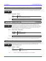
The Automatic Login Procedure (‘Non-NDS’ Print Servers)
This is the default login procedure for ‘Non-NDS’ Axis print servers. At start up the
print server logs in to every file server on the network; in this way the print server
gathers information about the print queue to printer connections.
Q: Are there any circumstances when I should disable the automatic login procedure?
A: Yes; if you have a large network this login method may take too long. In this case
you should consider using another login methods.
Q: How do I switch the automatic login on and off?
A: Simply click the Automatic Scanning box (under Print Server Mode and/or Remote
Printer Mode) as illustrated in the NetWare property page shown in figure 5-6.
The Parameter Controlled Login Procedure (‘Non-NDS’ Print Servers)
With this method the Axis print server holds the queue to printer information in its
login parameters. There are 16 of these parameters, so up to 16 sets of queue to printer
details can be held. Each parameter holds the name of a file server, a print queue and a
logical printer.
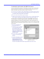
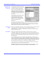
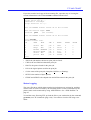
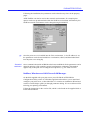
Q: How do I enter details into
these login parameters?
A: NetPilot does it for you. When
you use the Modify Network
Environments window (see
figure 5-5) to alter print queue
connections, NetPilot uses this
information to update the login
parameter details.
Q: How do I enable or disable the
parameter controlled login
method?
A: You don’t! The print server will
always use the information in
its login parameters, even if
Figure 5-5 Using NetPilot to inspect the queue to
other login methods have been
logical printer connections.
enabled. If more than 16 queues
are to be serviced then one of the other login methods must also be used.
The AXIS Network Print Server Technical Reference Revision 2.0
39
NETWORK PRINTING
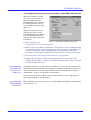
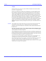
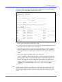
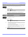
The Configuration File Server Login Procedure (‘Non-NDS’ Print Servers)
When this method is used the
print server gets its queue to
printer information from a
designated file server (known as
the Configuration File Server,
see the NetWare property page,
figure 5-6)
When the Axis print server is
powered-up it logs in to the
configuration file server named
in its CONFSERV parameter,
and reads the queue and printer
information.
Figure 5-6 - AXIS NetPilot’s NetWare Property Page
Q: When should I use the
Configuration File Server login method?
A: When you have more than 16 print queues - don’t bother to enter a configuration file
server name if you have 16 or less print queues. This is because as you assign queue
to printer connections, NetPilot automatically records the details in the login
parameters, so entering the configuration file server name as well is not necessary.
Q: How do I switch on the Configuration File Server login method?
A: Simply enter the file server name in the Configuration File Server box on the
NetWare Property Page - see figure 5-6. Make sure that the queues from 17 onwards
are located on this file server.
Login method for
‘Non-NDS’ Axis
Print Servers on
NetWare 4.x
Non-NDS print servers can only operate in NetWare 4.x systems if the contexts that
holds the print queues and print server objects have bindery emulation switched on. To
do this you will have to use one of the NetWare utilities, PCONSOLE or NetWare
Administrator - refer to your NetWare documentation.
Once you have done this, NetPilot can be used in the normal way to setup the print
server login methods as described above.
Login method for
NDS compatible
Print Servers
NDS compatible Axis print servers use one login method for NetWare 4.x and another
for NetWare 2.x/3.x.
The AXIS Network Print Server Technical Reference Revision 2.0
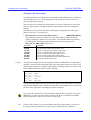
40
NETWORK PRINTING
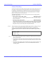
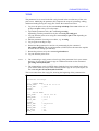
NDS compatible print server login procedure for NetWare 4.x
Because NetWare 4.x has a
distributed database it is only
necessary to define one file server
to the print server. All file servers
with physical queues will then
automatically be found and
logged into. Therefore only a
single parameter is needed; this
parameter holds the file server
name and the context for the print
server’s object in the NDS tree.
These details must be entered in
the Modify Network
Environments page, an example
of which is shown in figure 5-7.
The names are put in the boxes
seen under the heading:
NDS Print Server Definition, in
the lower part of the screen.
Figure 5-7 Print queue connections in NetWare NDS
Login procedure for NDS compatible print servers on NetWare 2.x or 3.x
The login procedure used is similar to the parameter controlled login used by a
‘Non-NDS’ print server. There is a set of 16 parameters (PSERVER_BINDERY1 to
16) which hold the names of any file servers with print queues connected to the print
server.
When the print server starts up it logs in to each of the file servers named in these
parameters, and extracts information from the file servers about queues that are to be
serviced, and also the printer ports that are to be used. Please note that there is no
support for logical printers on NDS compatible print servers when working within
NetWare; the queues are linked directly to the physical ports.
Print Server and
Remote Printer
Operating Modes
In print server mode the Axis unit behaves in the same way as a NetWare print server.
The Axis unit fetches print jobs from the queues and passes them to the printers that are
connected to its own ports. In this mode the Axis print server is taking the place of the
PSERVER software and printer driver software on the file server, therefore removing
some of the workload from the file server.
In remote printer mode an Axis unit port is connected to a NetWare print server. The
Axis unit is taking the place of the NPRINTER (or RPRINTER) software and printer
driver software running on the workstation. This method of operation is used in place
of a printer connected to a workstation, thereby preventing the workstation from being
interrupted whenever print data is being handled from the network.
Any of the Axis network print server ports can be operated in both print server mode
and remote printer mode at the same time. You select the operating mode when you
connect print queues to a port, as shown below.
The AXIS Network Print Server Technical Reference Revision 2.0
41
Novell NetWare: Print Methods
Connecting Print
Queues to Axis
print servers
NETWORK PRINTING
The print queue connections are made
in AXIS NetPilot by first selecting the
relevant port, and then clicking the
Connect... button - see figure 5-7 above.
The Connect NetWare Print Queues
dialog (shown on the right, figure 5-8)
is then used to select a print queue from
the NetWare Print Queue list shown in
the window.
The Print Queues shown in the window
will be those held on the resource
selected in the box at the top of the
screen. This may be a file server in a
NetWare 2.x or 3.x environment, or a
location in the NDS tree for
NetWare 4.x.
Figure 5-8 AXIS NetPilot’s Print Queue Setup Page
Having chosen the print queue that is to
be connected to the printer port, you should then select either Print Server Mode or
Remote Printer Mode. In the case of Remote Printer Mode you must also select the
NetWare print server that the port will be connected to.
Creating Print
Queues
In the case of ‘Non-NDS’ Axis print servers you can link the queue to one of the logical
printers by using !n in the name, where n = the logical printer number, e.g.
SALESDEPTQ!2. See “LOGICAL PRINTERS” on page 100. The default is logical
printer 1 connected to LPT1.
Print Methods
There are two different methods in NetWare to transfer a print job to a queue.
CAPTURE is the best choice when you want to print on a network printer from your
applications. NPRINT requires the additional step of creating a print file, but offers you
the choice between local and network printing at all times since it doesn’t occupy a
local printer port.
The CAPTURE program is used to capture output destined for a local printer and
redirect to a network print queue. When the CAPTURE command is issued, NETX (or
whichever shell you use) modifies DOS so that it lets the shell monitor the printer port
you are capturing. Any print data sent to that port by DOS or an application program is
intercepted and sent to the queue you named in the CAPTURE command.
If you later decide to stop capturing, issue the ENDCAP command. The shell stops
monitoring the printer port, and local printing resumes.
NPRINT is a replacement for (and an improvement on) the DOS PRINT command.
Use NPRINT when you want to print an existing file on a network printer.
The AXIS Network Print Server Technical Reference Revision 2.0
42
LAN Server/Lan Manager
NETWORK PRINTING
The table below shows a summary of the CAPTURE and NPRINT parameters:
Example:
Parameter
Short
Values
Default
CAPTURE
NPRINT
Show
Job=JobName
SH
J=
None
Default job
Yes
Yes
No
Yes
Queue= QueueName
Q=
Yes
S=
Yes
Yes
Local=n
Form=FormName (or = n)
L=
F=
Queue for
Spooler 0
Default
server
1
0
Yes
Server= ServerName
Yes
Yes
No
Yes
Create= Path
CR=
None
Yes
No
Copies=n
Timeout=n
Autoendcap
No Autoendcap
Keep
Tabs=n
No Tabs
Banner=BannerName
C=
TI=
A
NA
K
T=
NT
B=
1
8
On
Off
Off
8
Off
LST:
Yes
Yes
Yes
Yes
Yes
Yes
Yes
Yes
Yes
No
No
No
No
Yes
Yes
Yes
Name=Name
NAM=
Username
Yes
Yes
No Banner
Form Feed
No Form Feed
Notify
No Notify
Domain= DomainName
NB
FF
NFF
NOTI
NNOTI
DO=
Off
On
Off
Off
On
None
Yes
Yes
Yes
Yes
Yes
Yes
Yes
Yes
Yes
Yes
Yes
Yes
Delete
D
None
Any PRINTCON
job configuration
Any valid print
queue name
Any valid file
server name
1, 2, or 3
Any valid form
name or number
File name
including path
1-999
0-1000
None
None
None
0-18
None
Any string up to
12 characters
Any string up to
12 characters
None
None
None
None
None
Any valid NNS
domain name
None
Off
No
Yes
CAPTURE /L=1 /Q=DESKTOP /TI=30 /NT /NB /FF /NOTI
This command captures LPT1 print jobs and sends them to the queue DESKTOP with a
30 seconds time-out, no tab expansion, no banner page, appends a Form Feed, and
notifies when the printout is completed.
Windows, LAN Server/LAN Manager
The process of printing through a print server from within a LAN Server/LAN
Manager environment is managed by the AXIS Print Utility for OS/2. The AXIS Print
Utility for Windows manages the same process under a Windows environment. Both
utilities are delivered with your print server. Refer to the User’s Manual for instructions
on how to install and use these utilities.
The Axis print utilities are used to install the print servers on your network, and also to
show detailed information about each individual Axis print server port.
The AXIS Network Print Server Technical Reference Revision 2.0
43
Printing from IBM Hosts
NETWORK PRINTING
Under the AXIS Print Utility for OS/2, each Axis print server port is displayed as a
print queue and has a pipe name, e.g. \PIPE\AX110086_LP1. Print queue destinations
are referred to as devices in OS/2 version 1.x, and as ports in version 2.x and 3.x
(Warp). The Axis print server ports may be assigned as print queue destinations by
following the standard procedures under OS/2. These procedures are identical for LAN
Server/LAN Manager, but differs between OS/2 version 1.x and versions 2.x and 3.x
(Warp).
Print jobs can be sent indirectly through the file server from any MS-DOS, Windows or
OS/2 application. They can also be cancelled, held, etc., using standard procedures.
It is also possible to print directly from a workstation, given that it is running the AXIS
Print Utility for Windows or OS/2 software.
The following parameters control printing in this environment:
• LAN Server/LAN Manager Protocol Enabled (LSLM_ENB.)
This parameter switches the print server LAN Server/LAN Manager support on and
off. The default setting is YES. Changing to NO will disable the LAN Server/LAN
Manager support, and the printer ports will not appear in the AXIS Print Utility list.
• Printer 1 Name (LPRINT_1.)
This parameter specifies the name of the first network printer. The default name is
set to AX<nnnnnn>.LP1, where <nnnnnn> are the last six digits of the Axis print
server serial number. This may be changed to any name not exceeding 16
characters. The Printer 2 through Printer 8 names are specified by parameters:
LPRINT_2. to LPRINT_8.
• Printer 1 Logical Printer (LLOGIC_1.)
This parameter specifies the logical printer assigned to Printer 1. The default setting
is PR1. The Printer 2 through Printer 8 logical printers are specified by parameters:
LLOGIC_2. to LLOGIC_8.
Printing from IBM Hosts
The Axis print servers support printing from IBM hosts provided that the appropriate
software is installed on the server handling the host protocol (typically SNA) and the
IBM printer data streams. Examples of supported products are:
• IBM Communications Manager
• IBM PC Support
• IBM/Pennant PSF/2
Both IBM Communications Manager and IBM PC Support use standard OS/2 printer
drivers. Consequently, these products are able to generate almost any printer data
stream. PSF/2 enables distributed AFP printing but is limited to PCL and PPDS
printers, since it uses internal printer drivers.
Both PC Support and PSF/2 rely on Communications Manager for the host
communication.
The AXIS Network Print Server Technical Reference Revision 2.0
44
TCP/IP
NETWORK PRINTING
TCP/IP
Printing with the Axis print server in the TCP/IP environment can be done in either
interactive or integrated mode.
In Interactive Mode the Axis print server will appears as a host into which you may
login. Printing is performed as a host-to-host file transfer that uses FTP or Reverse
Telnet. The only preparation required is installing the print server on your network,
which includes finding a free Internet address and down-loading it to the print server.
When operating in Integrated Mode, the Axis print server is integrated into the host
printer spooler and therefore, the printer (or printers) will appear as directly connected
to the spooler. The installation procedure is initially the same as for the interactive
mode, but will additionally require that the print server is fully integrated into your host
spooler system. This may be performed either automatically or manually, whereby
automatic integration is done by running the axinstall script, as described in the User’s
Manual.
axinstall
The axinstall script is stored in the print server and is used to install it into the Unix
environment. Once the print server is installed into the Unix environment the
parameters can be down-loaded into a workstation, edited, and then loaded back into
the print server.
Due to the large number of hosts, Unix variation and print method combinations, there
will always be instances where axinstall will fail. For these cases, the following pages
contain guidelines for manual integration.
We recommend that you start by trying axinstall. However, should you experience any
problems during the integration, or if the test printout at the end of axinstall fails, then
the integration of the print server should be performed manually. The current version of
axinstall when this technical reference was produced was 1.8.
You can get a free axinstall update, or find out what the latest version number is, by
visiting the Axis on-line service. Refer to How To Contact Axis (page 280).
The installation and integration procedures are described individually for each type of
UNIX system (BSD, System V and IBM AIX) in this section. The installation
procedure is the same regardless of the print method, but you will have to select a print
method before carrying out the integration.
The AXIS Network Print Server Technical Reference Revision 2.0
45
TCP/IP: BSD-Type UNIX Systems
NETWORK PRINTING
Printing from BSD-Type UNIX Systems
The following print methods are available for BSD-type systems (Sun-OS, Ultrix, etc.).
Use the table below to select the print method that is best fitted for your printing
requirements. Detailed integration procedures are given for each method on the
following pages.
Print Method
Advantages
Limitations
LPD
Easy to set up – add a remote printer to
/etc/printcap using the rm and rp fields.
No printer status logging.
FTP
PROS A
Uses industry standard network software
on the host.
The communication with the Axis print
server is logged to a log file, including
printer status and feedback.
Easy to integrate – the print server
appears as a device to the system.
PROS B
All printcap options available, including
input/output filters.
The communication with the Axis print
server is logged to a log file, including
printer status and feedback.
All printcap options available, including
input or output filter.
Reverse Telnet
Easy to set up if Reverse Telnet drivers
are already installed.
The AXIS Network Print Server Technical Reference Revision 2.0
printcap capabilities are not available.
lpr options (e.g. multiple copies) are not
available.
No printer status logging.
May conflict with other input or output
filter.
Does not allow both input and output
filter.
A C compiler is required to build the
PROS drivers.
A daemon must be active for each
printer attached to the print server.
A C compiler is required to build the
PROS drivers.
May conflict with other input or output
filter.
Does not allow both input and output
filter.
No printer status logging.
Drivers are not supplied with the print
server. Existing drivers may be slow.
46
TCP/IP: BSD-Type UNIX Systems
The Printcap File
NETWORK PRINTING
BSD-type systems use the printcap file (printer capability data base) for describing
printers. The spooling system accesses the printcap file every time it is used, allowing
dynamic addition and deletion of printers. Each entry in the data base describes one
printer, and contains a number of fields separated by colons.
The first field is the abbreviation and the full name of the printer, separated by a ‘|’
character. The following fields contain printer capabilities, see the table below.
Entries may continue onto multiple lines by giving a ‘\’ as the last character of a line.
The table below summarizes the most common printer capabilities. For a complete list,
please refer to the printcap description in your Unix documentation.
Notes on the LPD
Print Method
Parameter
Type
Default
Description
ff= FormFeedStr
if= InputFilter
String
String
\f
NULL
lf= ErrorLogFile
String
NULL
lp=filename
String
/dev/lp
mx=MaxFileSize
Numeric
1000
of=OutputFilter
String
NULL
rm=RemoteMachine
String
NULL
rp=RemotePrinter
String
NULL
sd= SpoolDirectory
String
/usr/spool/lpd
sh
Boolean
FALSE
Specifies the Form Feed string.
Specifies an input filter. Print data passes
through this filter before it is written to the spool
directory.
Species the file where error reports are logged. If
this field is omitted, errors are logged to
/usr/adm/lpd-errs.
Specifies the file or device to which print data will
be sent.
Specifies the maximum file size in BUFSIZ
blocks (generally 1 kbyte). Larger files will be
truncated. mx=0 allows unlimited file sizes.
Specifies an output filter. Print data passes
through this filter at print-time.
Specifies a remote machine. Used by LPD as
the print server host name (alias).
Specifies a printer at a remote machine. Used by
LPD to specify an print server logical printer.
Specifies the spool directory where print jobs are
buffered.
Suppress header page. If omitted, the spooler
will insert a header page before each print job.
The LPD protocol was developed as a remote print method for Berkeley type UNIX
hosts. It was primarily intended for transmission of print jobs between hosts rather than
to a print server. Due to the design of the LPD protocol, there will be some limitations
when printing via a print server as explained below.
LPD operates by a few commands and the transfer of two files – the control file, and
the data file. The control file contains information such as user ID, number of copies,
banner page information, and system specific information. The data file contains the
raw print data.
When the print data reaches its destination host for interpretation using the printcap
file, it is normally intended to be printed locally. But, in the case of remote printing (i.e.
using a print server), the LPD daemon often transmits data to the remote host in
reversed order; first the data file, then the control file.
The AXIS Network Print Server Technical Reference Revision 2.0
47
TCP/IP: BSD-Type UNIX Systems
NETWORK PRINTING
If the remote host is a workstation or a mainframe, the reversed order poses no
problems; the actual printing will not start until both files are received and processed.
However, for a print server with it’s limited data storage capabilities, the reversed order
represents a major problem. Adding a hard disk or more memory is one possible
solution, but today’s large print jobs with hundreds of kilobytes per page would
generate unnecessary delays when the printing cannot start until all data is transferred.
There would also be a size limitation of the print jobs depending on the amount of
installed memory.
The Axis solution is to process the control file after the print job is done, thus
eliminating the delays and file size limitations. The drawback is that the banner page
will be printed after the print job itself, and that functions like multiple copies and
filters will not be supported. If you can do without these functions, the LPD print
method is recommended due to the simple integration procedure, otherwise choose one
of the other print methods.
Installation
Regardless of the printing mode you intend to use, the first step is to install the Axis
print server on your host. Please note that the installation and integration procedures
require that you have root privileges on the system.
Start with assigning an Internet Address and a host name (alias) to the print server by
adding the following line to your system host table (/etc/hosts):
Example:
192.36.253.96
salesdept
(192.36.253.96 and salesdept are examples only)
DO NOT use the default or example Internet address when installing your print server.
Always consult your network manager before assigning an Internet Address.
If applicable, update your alias name data bases (Yellow Pages, YP/NIS), typically by
the commands cd /var/yp and make.
The next step is to down-load the Internet Address to the print server. This can be done
in three ways, using either the arp, rarp, or bootp method.
Setting the
Internet Address
using arp
Enter the following commands to set the Internet Address. The alias (salesdept) must
match the one assigned above, and the Ethernet Address (here 00:40:8c:10:00:86)
should equal the serial number of your print server:
arp -s salesdept 00:40:8c:10:00:86 temp
ping salesdept
(salesdept and 00:40:8c:10:00:86 are examples only)
The host should respond ‘salesdept is alive’ or something similar to indicate that
communication is established.
Notes:
1. The syntax of the arp command is system dependent. Consult your host’s reference
manual (or use the man arp command) if you’re uncertain about the proper syntax.
The AXIS Network Print Server Technical Reference Revision 2.0
48
TCP/IP: BSD-Type UNIX Systems
NETWORK PRINTING
2. If you need to run the arp command again, the print server must be restarted
(power-off/power-on) before it can accept a new Internet Address.
3. If rarp or bootp is running on your network and the print server is present in
/etc/ethers, it is not possible to change the Internet Address using the arp
command.
4. The print server and the host must be on the same logical network segment (not
separated by a router).
Setting the
Internet Address
using rarp
The rarp method sets the Internet address automatically every time the Axis print
server is powered on. The main advantage with this is that you don’t have to down-load
the Internet address individually to each print server as when using the arp method.
This is how it works: The print server broadcasts a request to a rarp daemon at
power-up. If the daemon is active, and a matching entry is found in the Ethernet
Address Table, the daemon down-loads the Internet address to the print server. If the
daemon isn’t active or the table entry isn’t found, the Internet address remains
unchanged.
Follow these steps to use the rarp method:
1. Update your host table (/etc/hosts) as described earlier.
2. Edit the Ethernet Address table on your host (typically the file /etc/ethers) by
appending the following line:
00:40:8c:10:00:86
salesdept
(salesdept and 00:40:8c:10:00:86 are examples only)
3. Start the rarp daemon (if it isn’t already running) by the command rarpd -a (this is
system dependent, consult your system documentation).
4. Restart the print server to down-load the Internet address.
Setting the
Internet Address
using bootp
The bootp method is similar to rarp but gives two additional advantages:
• The network configuration data for the entire network can be in one place which
makes it easy to maintain.
• In addition to the Internet address, the default router address and the net mask are
down-loaded to the print server automatically every time it is powered on.
This is how it works: The print server broadcasts a request containing its Ethernet
address to a bootp daemon at power-up. If the daemon is active, and a matching entry is
found in the Boot Table, the daemon down-loads the Internet address, default router
address and net mask to the print server. If the daemon isn’t active or the table entry
isn’t found, the Internet address, default router address and net mask remains
unchanged.
Follow these steps to use the bootp method:
1. Update your host table (/etc/hosts) as described earlier.
2. Edit (or create) the boot table on your host (typically the file /etc/bootptab) by
appending the following entry:
The AXIS Network Print Server Technical Reference Revision 2.0
49
TCP/IP: BSD-Type UNIX Systems
NETWORK PRINTING
salesdept:ht=ether:vm=rfc1048:ha=00408c100086:\
:ip=192.36.253.96:sm=255.255.255.0:\
:gw=192.36.253.254
(salesdept and the ha, ip, sm, and gw fields are examples only)
• ht= is the Hardware Type field. Set this to ether for Ethernet, or tr for Token
Ring.
• vm= is the Vendor Magic field, specifying bootp report format. Should typically
be rfc1048.
• ha= is the Hardware Address field. Set this to the Ethernet address or Token
Ring node address of your print server.
• ip= is the Internet Address field. Set this to the Internet address of your print
server.
• sm= is the Subnet Mask field. Set this to the net mask value for your network.
• gw= is the Gateway field. Set this to your default router address.
3. Start the bootp daemon (if it isn’t already running) by the command bootpd (this is
system dependent, consult your system documentation).
4. Restart the print server to down-load the Internet address, default router address
and net mask.
Integration for LPD Printing
This is the recommended print method for BSD-type systems. It is easy to set up, but is
also fairly limited. The drawbacks are that printcap capabilities other than rm, rp, and
sd are not supported, neither are lpr options such as multiple copies available.
Automatic
Integration
(LPD Printing)
Manual
Integration
Run the axinstall script and follow the instructions on the screen. Choose LPD at the
Print Method prompt.
If axinstall fails to provide a satisfactory integration for any reason, then follow the
manual integration method shown below. The current version of axinstall when this
technical reference was produced was 1.8. You can get a free axinstall update, or find
out what the latest version number is, by visiting the Axis on-line service, refer to How
To Contact Axis (page 280).
1. Add the following line to your printcap file:
(LPD Printing)
sales_1|AXIS 560 LPT1 at salesdept:lp=:rm=salesdept:\
:rp=pr1:sd=/usr/spool/sales_1
• sales_1 is the short name for the printer
• AXIS 560 LPT1 at salesdept is the full printer name
• lp= doesn’t do anything, but is required by some systems
• rm=salesdept is the host name (alias) of your print server
• rp=pr1 specifies the logical printer for sales_1
• sd=/usr/spool/sales_1 is the spool directory
2. Create a spooling directory by the command mkdir /usr/spool/sales_1.
The AXIS Network Print Server Technical Reference Revision 2.0
50
TCP/IP: BSD-Type UNIX Systems
Test Printout
(LPD Printing)
Integration of
additional printers
(LPD Printing)
NETWORK PRINTING
Print the file test using the lpr command:
lpr -Psales_1 test
Repeat the integration process (automatically or manually) for each additional printer
attached to your print server. Each printer must have its own printcap entry as well as a
unique name and spool directory.
Integration for FTP Printing
The FTP print method is a bit more complex to set up than LPD, but offers more
printing options. This is the method to choose if you intend to use printcap capabilities
not available through LPD, but don’t need the additional features offered by PROS
(such as printer status logging).
Automatic
Integration
(FTP Printing)
Run the axinstall script and follow the instructions on the screen. Choose FTP at the
Print Method prompt.
If axinstall fails to provide a satisfactory integration for any reason, then follow the
manual integration method shown below. The current version of axinstall when this
technical reference was produced was 1.8. You can get a free axinstall update, or find
out what the latest version number is, by visiting the Axis on-line service, refer to How
To Contact Axis (page 280).
Note:
The automatic integration only provides basic printing functions (no banner page, etc.).
To get full control over the printcap capabilities, edit the printcap file after the
automatic integration or use the manual integration.
Manual
Integration
1. Login to the Axis print server using FTP, and up-load the files ftp_bsd and
printcap.ftp from the bsd directory.
2. Copy ftp_bsd to ftp_bsd-sales_1.
3. Edit ftp_bsd-sales_1 as described in the file header. This is where you specify the
Internet Address, Logical Printer, FTP path, user name and password.
4. Move the modified file to the directory where you keep your printer filters, and
make it executable by the command chmod +x ftp_bsd-sales_1.
5. Create a error log file by the command touch /usr/adm/sales_1-log.
6. Create a spool directory by the commands cd /usr/spool and mkdir sales_1.
7. Create a printer spooler dummy file by the command touch sales_1/null.
8. Edit printcap.ftp as described in the file header (see example below). This is the
point where you should tailor the printer capabilities to meet your specific needs.
9. Append the new printcap entry by the command cat printcap.ftp >> /etc/printcap.
(FTP Printing)
Example:
This is what the new printcap entry might look like:
The AXIS Network Print Server Technical Reference Revision 2.0
51
TCP/IP: BSD-Type UNIX Systems
NETWORK PRINTING
sales_1|AXIS 560 LPT1 at salesdept:\
:lp=/usr/spool/sales_1/null:\
:ff=\r\f:sh:lf=/usr/adm/sales_1-log:\
:of=/usr/local/lib/ftp_bsd-sales_1:\
:sd=/usr/spool/sales_1
It is not allowed to use input filters with the FTP print method. However, you may
combine the ftp_bsd filter with your own output filter by taking the following steps:
1. Create a script called newfilter containing the lines below in the /usr/local/lib
directory (or wherever you keep your printer filters).
#!/bin/sh
/usr/local/lib/myfilter | /usr/local/lib/ftp_bsd-sales_1
2. Make the script executable by the command chmod +x newfilter.
3. Replace ftp_bsd-sales_1 with newfilter in the output filter (of) field of your new
printcap entry.
Test Printout
Print the file test using the lpr command:
(FTP Printing)
lpr -Psales_1 test
Integration of
additional printers
(FTP Printing)
Example:
Repeat the integration process (automatically or manually) for each additional printer
attached to your print server. Each printer must have its own printcap entry and output
filter as well as a unique name and spool directory.
These are the two new printcap entries required when integrating two printers at the
salesdept print server:
sales_1|AXIS 560 LPT1 at salesdept:\
:lp=/usr/spool/sales_1/null:\
:ff=\r\f:sh:lf=/usr/adm/sales_1-log:\
:of=/usr/local/lib/ftp_bsd-sales_1:\
:sd=/usr/spool/sales_1
sales_2|AXIS 560 LPT2 at salesdept:\
:lp=/usr/spool/sales_2/null:\
:ff=\r\f:sh:lf=/usr/adm/sales_2-log:\
:of=/usr/local/lib/ftp_bsd-sales_2:\
:sd=/usr/spool/sales_2
Integration for PROS A Printing
PROS A is the most powerful print method, featuring full support of the printcap
capabilities as well as automatic logging of printer status and feedback. It is fairly easy
to integrate since the print server appears as a device (Named Pipe) to the system. The
drawbacks are that you must run a PROS daemon for each printer, and you also need a
C compiler on your host to make the PROS daemon.
If you don’t have a C compiler, use the FTP method described above. If you have a
compiler, but don’t want to run daemons on your system, use the almost as powerful
PROS B method.
The AXIS Network Print Server Technical Reference Revision 2.0
52
TCP/IP: BSD-Type UNIX Systems
Automatic
Integration
(PROS A Printing)
NETWORK PRINTING
Run the axinstall script and follow the instructions on the screen. Choose PROS A at
the Print Method prompt.
If axinstall fails to provide a satisfactory integration for any reason, then follow the
manual integration method shown below. The current version of axinstall when this
technical reference was produced was 1.8. You can get a free axinstall update, or find
out what the latest version number is, by visiting the Axis on-line service, refer to How
To Contact Axis (page 280).
Note:
The automatic integration only provides basic printing functions (no banner page, etc.).
To get full control over the printcap capabilities, edit the printcap file after the
automatic integration or use the manual integration.
Manual
Integration
1. Create and move to a directory for the print server daemon using the commands
mkdir /usr/local/lib/axis and cd /usr/local/lib/axis.
2. Login to the print server using FTP and up-load the files makefile and prosd.c from
the npipe directory.
3. Edit the makefile to fit your system requirements as described in the file header.
4. Use make to compile the PROS daemon.
5. Create a named pipe for the printer by the command mknod /dev/salesdept.pr1 p,
where salesdept is the alias for the print server, and pr1 is the logical printer.
6. To make the daemon start automatically when booting up your host, add the
following statement to one of the system start-up files (e.g. /etc/rc.local):
(PROS A Printing)
/usr/local/lib/axis/prosd myhost /dev/salesdept.pr1 salesdept
pr1 netprinter 2> /usr/adm/salesdept_pr1_log 1>&2 &
If you want to store the printer feedback data in a separate file, use this statement:
/usr/local/lib/axis/prosd myhost /dev/salesdept.pr1 salesdept
pr1 netprinter 2> /usr/adm/salesdept_pr1_log 1>>
/usr/adm/salesdept_pr1_pfb &
•
•
•
•
•
•
•
•
/usr/local/lib/axis/prosd is the path and file name of the PROS daemon
myhost is the name of the host where you are doing the integration
/dev/salesdept.pr1 is the path and file name of the named pipe
salesdept is the name of your print server
pr1 is the logical printer to be used
netprinter is the PROS protocol password
/usr/adm/salesdept_pr1_log is the path and file name of the error log file
/usr/adm/salesdept_pr1_pfb is the path and file name of the printer readback data
file.
7. Start the Bourne shell, if you’re not already there, by the command sh.
8. Start a daemon by the command nohup followed by one of the statements given at
step 6 above.
9. Create a spooler directory by the command mkdir /usr/spool/sales_1.
The AXIS Network Print Server Technical Reference Revision 2.0
53
TCP/IP: BSD-Type UNIX Systems
NETWORK PRINTING
10. Add a printcap entry for the printer to /etc/printcap. All printcap capabilities are
available, including both input and output filters. The printcap entry should contain
at least the following fields:
sales_1|AXIS 560 LPT1 at salesdept:\
:lp=/dev/salesdept.pr1:\
:sd=/usr/spool/sales_1
Note:
Test Printout
Ultrix systems may require an output filter to work properly. If you are not using a
filter, there is a straight-through dummy filter called xf that can be used by adding a
:of=xf: field to the printcap entry.
Test the PROS daemon by printing the file test using the cat command:
(PROS A Printing)
cat test > /dev/salesdept.pr1
If the daemon works, print the file through the spooler using lpr:
lpr -Psales_1 test
Integration of
additional printers
(PROS A Printing)
Repeat the integration process (automatically or manually) for each additional printer
attached to your print server. Each printer must have its own daemon, printcap entry, a
unique name and spool directory. If you integrate manually, note that the first three
steps (i.e. compiling the PROS daemon) need only to be done once.
Integration for PROS B Printing
PROS B uses an output filter rather than a daemon. The integration procedure is
therefore similar to FTP, with the additional step of compiling the PROS drivers. It
retains all the features of PROS A except the simultaneous use of both input and output
filters.
If you don’t have a C compiler, use the FTP method described above.
Automatic
Integration
(PROS B Printing)
Note:
Manual
Integration
Run the axinstall script and follow the instructions on the screen. Choose PROS B at
the Print Method prompt.
If axinstall fails to provide a satisfactory integration for any reason, then follow the
manual integration method shown below. The current version of axinstall when this
technical reference was produced was 1.8. You can get a free axinstall update, or find
out what the latest version number is, by visiting the Axis on-line service, refer to How
To Contact Axis (page 280).
The automatic integration only provides basic printing functions (no banner page, etc.).
To get full control over the printcap capabilities, edit the printcap file after the
automatic integration or use the manual integration.
1. Create a work directory by the command mkdir /usr/local/lib/axis.
(PROS B Printing)
The AXIS Network Print Server Technical Reference Revision 2.0
54
TCP/IP: BSD-Type UNIX Systems
NETWORK PRINTING
2. Login to the print server using FTP and up-load the files makepros, prosbsd.c, and
printcap.pro from the bsd directory to the work directory.
3. Edit the file makepros as described in the file header. This is where you specify the
name of the host to integrate the printer on, the alias for your print server, the
logical printer to use, output filter name, and printer feedback data destination.
4. Compile the executable prosbsd filter by the command sh makepros.
5. Rename prosbsd to prosbsd-sales_1 and move it the directory where you keep your
printer filters by the command. cp prosbsd /usr/local/lib/prosbsd-sales_1.
6. Create a error log file by the command touch /usr/adm/sales_1-log.
7. Create a spool directory by the commands cd /usr/spool and mkdir sales_1.
8. Create a printer spooler dummy file by the command touch sales_1/null.
9. Edit printcap.pro as described in the file header (see example below). This is the
point where you should tailor the printer capabilities to meet your specific needs.
10. Append the printcap entry by the command cat printcap.pro >> /etc/printcap.
Example:
This is what the new printcap entry might look like:
sales_1|AXIS 560 LPT1 at salesdept:\
:lp=/usr/spool/sales_1/null:\
:ff=\r\f:sh:lf=/usr/adm/sales_1-log:\
:of=/usr/local/lib/prosbsd-sales_1:\
:sd=/usr/spool/sales_1
It is not allowed to use both input and output filters with the PROS B print method.
However, you may combine the prosbsd filter with your own output filter by taking the
following steps:
1. Create a script called newfilter containing the lines below in the /usr/local/lib
directory (or wherever you keep your printer filters).
#!/bin/sh
/usr/local/lib/myfilter | /usr/local/lib/prosbsd-sales_1
2. Make the script executable by the command chmod +x newfilter.
3. Replace prosbsd-sales_1 with newfilter in the output filter (of) field of your new
printcap entry.
Using the PROS
driver as Input
Filter
Test Printout
We recommend you to use the PROS driver as output filter since this enables banner
pages and Form Feeds between jobs to be processed by the spooler. If you don’t require
these functions, you may install prosbsd as an input filter by replacing the :of= field by
an :if= field in the printcap entries. The main reason for using input filters is that the
user ID appears in the accounting list.
Test the PROS driver by printing the file test using the cat command:
cat test | /usr/local/lib/prosbsd-sales_1
If the driver works, print the file through the spooler using lpr:
lpr -Psales_1 test
The AXIS Network Print Server Technical Reference Revision 2.0
55
TCP/IP: BSD-Type UNIX Systems
Integration of
Additional
Printers
NETWORK PRINTING
Repeat the integration process (automatically or manually) for each additional printer
attached to your print server. Each printer must have its own printcap entry and output
filter as well as a unique name and spool directory.
(PROS B Printing)
Example:
These are the two new printcap entries required when integrating two printers at the
salesdept print server:
sales_1|AXIS 560 LPT1 at salesdept:\
:lp=/usr/spool/sales_1/null:\
:ff=\r\f:sh:lf=/usr/adm/sales_1-log:\
:of=/usr/local/lib/prosbsd-sales_1:\
:sd=/usr/spool/sales_1
sales_2|AXIS 560 LPT2 at salesdept:\
:lp=/usr/spool/sales_2/null:\
:ff=\r\f:sh:lf=/usr/adm/sales_2-log:\
:of=/usr/local/lib/prosbsd-sales_2:\
:sd=/usr/spool/sales_2
The AXIS Network Print Server Technical Reference Revision 2.0
56
TCP/IP: System V UNIX Systems
NETWORK PRINTING
Printing from System V UNIX Systems
The following print methods are available for System V systems (Solaris, HP-UX,
SCO UNIX, Interactive UNIX, etc.). Use the table below to select the print method that
is best fitted for your printing requirements. Detailed integration procedures are given
for each method on the following pages.
Print Method
Advantages
Limitations
FTP
Uses industry standard network software
on the host.
No printer status logging.
PROS A
The communication with the Axis print
server is logged to a log file, including
printer status and feedback.
Easy to integrate – the print server
appears as a device to the system.
PROS B
LPD
No filters or interface programs can be
used.
A C compiler is required to build the
PROS drivers.
A daemon must be active for each
printer attached to the print server.
Any filters and interface programs can
be used.
Fatal errors are mailed to the user that
initiated the print job.
A C compiler is required to build the
PROS drivers.
Easy to set up.
No filters or interface programs can be
used.
No printer status logging.
lp options are not available. No filters or
interface programs can be used.
Reverse Telnet
Installation
Easy to set up if Reverse Telnet drivers
are already installed.
Not available on all System V UNIX
systems.
No printer status logging.
Drivers are not supplied with the print
server. Existing drivers may be slow.
Regardless of the printing mode you intend to use, the first step is to install the Axis
print server on your host. Please note that the installation and integration procedures
require that you have root privileges on the system.
Start with assigning an Internet Address and a host name (alias) to the print server by
adding the following line to your system host table (/etc/hosts):
192.36.253.96
salesdept
(192.36.253.96 and salesdept are examples only)
DO NOT use the default or example Internet address when installing your print server.
Always consult your network manager before assigning an Internet Address.
If applicable, update your alias name data bases (Yellow Pages, YP/NIS), typically by
the commands cd /var/yp and make.
The next step is to down-load the Internet Address to the print server. This can be done
in three ways, using either the arp, rarp, or bootp method.
Setting the
Internet Address
using arp
Enter the following commands to set the Internet Address. The alias (salesdept) must
match the one assigned above, and the Ethernet Address (here 00:40:8c:10:00:86)
should equal the serial number of your print server:
The AXIS Network Print Server Technical Reference Revision 2.0
57
TCP/IP: System V UNIX Systems
NETWORK PRINTING
arp -s salesdept 00:40:8c:10:00:86 temp
ping salesdept
(salesdept and 00:40:8c:10:00:86 are examples only)
The host should respond salesdept is alive or something similar to indicate that
communication is established.
Notes:
Setting the
Internet Address
using rarp
1. The syntax of the arp command is system dependent. Consult your host’s reference
manual (or use the man arp command) if you’re uncertain about the proper syntax.
2. If you need to run the arp command again, the print server must be restarted
(power-off/power-on) before it can accept a new Internet Address.
3. If rarp or bootp is running on your network and the print server is present in
/etc/ethers, it is not possible to change the Internet Address using the arp
command.
4. The print server and the host must be on the same logical network segment (not
separated by a router).
The rarp method sets the Internet address automatically every time the print server is
powered on. The main advantage with this is that you don’t have to down-load the
Internet address individually to each print server as when using the arp method.
This is how it works: The print server broadcasts a request to a rarp daemon at
power-up. If the daemon is active, and a matching entry is found in the Ethernet
Address Table, the daemon down-loads the Internet address to the print server. If the
daemon isn’t active or the table entry isn’t found, the Internet address remains
unchanged.
Follow these steps to use the rarp method:
1. Update your host table (/etc/hosts) as described earlier.
2. Edit the Ethernet Address table on your host (typically the file /etc/ethers) by
appending the following line:
00:40:8c:10:00:86
salesdept
(salesdept and 00:40:8c:10:00:86 are examples only)
3. Update your alias name data bases (Yellow Pages, YP/NIS), typically by the
commands cd /var/yp and make.
4. Start the rarp daemon (if it isn’t already running) by the command rarpd -a (this is
system dependent, consult your system documentation).
5. Restart the print server to down-load the Internet address.
Setting the
Internet Address
using bootp
The bootp method is similar to rarp but gives two additional advantages:
• The network configuration data for the entire network can be in one place which
makes it easy to maintain.
• The Internet address, the default router address, and the net mask are down-loaded
to the print server automatically every time it is powered on.
The AXIS Network Print Server Technical Reference Revision 2.0
58
TCP/IP: System V UNIX Systems
NETWORK PRINTING
This is how it works: The print server broadcasts a request containing its Ethernet
address to a bootp daemon at power-up. If the daemon is active, and a matching entry is
found in the Boot Table, the daemon down-loads the Internet address, default router
address and net mask to the print server. If the daemon isn’t active or the table entry
isn’t found, the Internet address, default router address and net mask remains
unchanged.
Follow these steps to use the bootp method:
1. Update your host table (/etc/hosts) as described earlier.
2. Edit (or create) the boot table on your host (typically the file /etc/bootptab) by
appending the following entry:
salesdept:ht=ether:vm=rfc1048:ha=00408c100086:\
:ip=192.36.253.96:sm=255.255.255.0:\
:gw=192.36.253.254
(salesdept and the ha, ip, sm, and gw fields are examples only)
• ht= is the Hardware Type field. Set this to ether for Ethernet, or tr for Token
Ring.
• vm= is the Vendor Magic field, specifying bootp report format. Should typically
be rfc1048.
• ha= is the Hardware Address field. Set this to the Ethernet address or Token
Ring node address of your print server.
• ip= is the Internet Address field. Set this to the Internet address of your print
server.
• sm= is the Subnet Mask field. Set this to the net mask value for your network.
• gw= is the Gateway field. Set this to your default router address.
3. Start the bootp daemon (if it isn’t already running) by the command bootpd (this is
system dependent, consult your system documentation).
4. Restart the print server to down-load the Internet address, default router address
and net mask.
Integration for LPD Printing
This is the recommended print method for System V systems where available,
otherwise FTP is recommended. While it is easy to set up it is also rather limited. The
drawbacks are that lp options, such as multiple copies, are not supported.
Automatic
Integration
(LPD Printing)
Notes:
Run the axinstall script and follow the instructions on the screen. Choose LPD at the
Print Method prompt.
If axinstall fails to provide a satisfactory integration for any reason, then follow the
manual integration method shown below. The current version of axinstall when this
technical reference was produced was 1.8. You can get a free axinstall update, or find
out what the latest version number is, by visiting the Axis on-line service, refer to How
To Contact Axis (page 280).
LPD is not available on all System V systems.
The AXIS Network Print Server Technical Reference Revision 2.0
59
TCP/IP: System V UNIX Systems
Manual
Integration
(LPD Printing)
Test Printout
NETWORK PRINTING
1. Enter the Bourne shell by the commands sh, SHELL=/bin/sh, and
export SHELL.
2. Login to the print server using FTP, and up-load the file ftp_sysv from the sysv
directory to the interface program directory.
3. Turn off the LP printer service by the command /usr/lib/lpshut.
4. Create a new system printer by the command
/usr/lib/lpadmin -p sales_1 -s salesdept!pr1 -l “any”, where sales_1 is the name
of the new printer, and salesdept is the host name of your print server, pr1 specifies
the logical printer for sales_1.
5. Restart the LP printer service by the command /usr/lib/lpsched.
6. Enable requests for print jobs on the new printer by the command
/usr/lib/accept sales_1, and enable the printer by /usr/bin/enable sales_1.
7. Exit the Bourne shell by exit.
Print the file through the spooler using lp:
(LPD Printing)
lp -d sales_1 test
Integration of
additional printers
(LPD Printing)
Repeat the integration process (automatically or manually) for each additional printer
attached to your Axis print server. Each printer must have its own interface program as
well as a unique name.
Integration for FTP Printing
This is the recommended print method for System V systems if LPD is not available. It
does not require a C compiler and BSD socket-type networking supports as the PROS
methods do, but has the drawback of not supporting status logging and filters or
interface programs.
Automatic
Integration
(FTP Printing)
Note:
Manual
Integration
(FTP Printing)
Run the axinstall script and follow the instructions on the screen. Choose FTP at the
Print Method prompt.
If axinstall fails to provide a satisfactory integration for any reason, then follow the
manual integration method shown below. The current version of axinstall when this
technical reference was produced was 1.8. You can get a free axinstall update, or find
out what the latest version number is, by visiting the Axis on-line service, refer to How
To Contact Axis (page 280).
There is no real reason to integrate manually for FTP unless you want to modify the
interface program in some way. We recommend that you start with automatic
integration, and turn to manual only if axinstall for some reason fails.
1. Create a directory to keep the print server interface programs by the command
mkdir /usr/local/lib/axis.
2. Login to the print server using FTP, and up-load the file ftp_sysv from the sysv
directory to the interface program directory.
3. Copy ftp_sysv to ftp_sysv-sales_1.
The AXIS Network Print Server Technical Reference Revision 2.0
60
TCP/IP: System V UNIX Systems
NETWORK PRINTING
4. Edit ftp_sysv-sales_1 as described in the file header. This is where you specify the
Internet Address, Logical Printer, FTP path, user name and password.
5. Make the modified file executable by the command chmod +x ftp_sysv-sales_1.
6. Enter the Bourne shell (if not already there) by the commands sh, SHELL=/bin/sh,
and export SHELL.
7. Turn off the LP printer service by the command /usr/lib/lpshut.
8. Create a new system printer by the command
/usr/lib/lpadmin -p sales_1 -i ftp_sysv-sales_1 -v /dev/null, where sales_1 is the
name of the new printer.
9. Restart the LP printer service by the command /usr/lib/lpsched.
10. Enable requests for print jobs on the new printer by the command
/usr/lib/accept sales_1, and enable the printer by /usr/bin/enable sales_1.
11. Exit the Bourne shell by exit.
Test Printout
Start by printing the file test using the interface program:
ftp_sysv-sales_1 x x x 1 x test
The ‘x’ characters represent parameters required by the system. They must be present,
but the values are ignored. The ‘1’ is the number of copies.
If the interface program works, print the file through the spooler using lp:
lp -d sales_1 test
Integration of
Additional
Printers
Repeat the integration process (automatically or manually) for each additional printer
attached to your print server. Each printer must have its own interface program as well
as a unique name.
(FTP Printing)
Integration for PROS A Printing
PROS A is the most powerful print method, featuring automatic logging of printer
status and feedback as well as allowing you to use any existing filters or interface
programs. It is fairly easy to integrate since the print server appears as a device (Named
Pipe) to the system. The drawbacks are that you must run a PROS daemon for each
printer, and you also need a C compiler on your host to make the PROS daemon.
If you don’t have a C compiler, use the FTP method described above. If you have a
compiler, but don’t want to run daemons on your system, use the almost-as-powerful
PROS B method.
Automatic
Integration
(PROS A Printing)
Run the axinstall script and follow the instructions on the screen. Choose PROS A at
the Print Method prompt.
If axinstall fails to provide a satisfactory integration for any reason, then follow the
manual integration method shown below. The current version of axinstall when this
technical reference was produced was 1.8. You can get a free axinstall update, or find
out what the latest version number is, by visiting the Axis on-line service, refer to How
To Contact Axis (page 280).
The AXIS Network Print Server Technical Reference Revision 2.0
61
TCP/IP: System V UNIX Systems
Note:
Manual
Integration
(PROS A Printing)
Note:
NETWORK PRINTING
There is generally no real reason to integrate manually for PROS A. We recommend
that you start with automatic integration, and turn to manual only if you experience
problems with axinstall.
1. Create and move to a directory for the print server daemon using the commands
mkdir /usr/local/lib/axis and cd /usr/local/lib/axis.
2. Login to the print server using FTP and up-load the files makefile and prosd.c from
the npipe directory.
3. Edit makefile according to the instructions in the file header. (Some System V
systems require L1_OPTIONS and L2_OPTIONS modifications, which is one of
the reason that axinstall might fail).
4. Use make to compile the PROS daemon.
5. Create a named pipe for the printer by the command mknod /dev/salesdept.pr1 p,
where salesdept is the alias for the print server, and pr1 is the logical printer.
6. Make the pipe accessible from lp only by the commands
chown lp /dev/salesdept.pr1 and chmod 600 /dev/salesdept.pr1.
7. To make the daemon start automatically when booting up your host, add the
following statement to one of the system start-up files (e.g. /etc/inittab):
Some systems recreate /etc/inittab at boot-time. To make sure that your added
statement are not lost, you should also put the statements in a file named
/etc/conf/init.d/axis-init. (Any file name will do, as long as it is placed in the init.d
directory).
If you prefer to start the daemon manually, skip to step 9 below.
axis::respawn:/usr/local/lib/axis/prosd myhost
/dev/salesdept.pr1 salesdept pr1 netprinter 2>
/usr/adm/salesdept_pr1_log 1>&2
If you want to store the printer feedback data in a separate file, use this statement:
axis::respawn:/usr/local/lib/axis/prosd myhost
/dev/salesdept.pr1 salesdept pr1 netprinter 2>
/usr/adm/salesdept_pr1_log 1>> /usr/adm/salesdept_pr1_pfb
•
•
•
•
•
•
•
•
/usr/local/lib/axis/prosd is the path and file name of the PROS daemon
myhost is the name of the host where you are doing the integration
/dev/salesdept.pr1 is the path and file name of the named pipe
salesdept is the name of your print server
pr1 is the logical printer to be used
netprinter is the PROS protocol password
/usr/adm/salesdept_pr1_log is the path and file name of the error log file
/usr/adm/salesdept_pr1_pfb is the path and file name of the printer read-back
data file.
8. Start the daemon by the command telinit q.
9. Enter the Bourne shell (if not already there) by the commands sh, SHELL=/bin/sh,
and export SHELL.
The AXIS Network Print Server Technical Reference Revision 2.0
62
TCP/IP: System V UNIX Systems
NETWORK PRINTING
10. If you did not start the daemon automatically according to steps 7-8 above, start it
now by the command nohup followed by one of the statements given at step 7
(leave out the axis::respawn: part, and append a ‘&’ character to make the daemon
run in the background).
11. Turn off the LP printer service by the command /usr/lib/lpshut.
12. Create a new system printer by the command
/usr/lib/lpadmin -p sales_1 -m standard -v /dev/salesdept.pr1, where sales_1 is
the name of the new printer and salesdept.pr1 is the daemon. You may use any
interface program by replacing standard with the name of the interface program.
13. Restart the LP printer service by the command /usr/lib/lpsched.
14. Enable requests for print jobs on the new printer by the command
/usr/lib/accept sales_1, and enable the printer by /usr/bin/enable sales_1.
15. Exit the Bourne shell by exit.
Test Printout
Test the PROS daemon by printing the file test using the cat command:
(PROS A Printing)
cat test > /dev/salesdept.pr1
If the daemon works, print the file through the spooler using lpr:
lp -d sales_1 test
Integration of
Additional
Printers
(PROS A Printing)
Repeat the integration process (automatically or manually) for each additional printer
attached to your print server. Each printer must have its own daemon and system
printer entry. Also, each inittab entry must have a unique label (‘axis’ in the previous
examples).
If you integrate manually, note that the first four steps (i.e. compiling the PROS
daemon) need only to be done once.
Stopping the
PROS Daemon
Should you ever want to stop a PROS daemon running on your system, this must be
done in different ways depending on how the daemon was started.
• If the daemon was started automatically (steps 7-8 above), you should stop it by
replacing respawn with off in the inittab entry, and then run telinit q to initialize the
new inittab settings.
• If the daemon was started manually (step 10 above), first find out the daemon’s
process number by the command ps -elf | grep prosd, then stop the daemon by the
command kill -9 <process number>.
Integration for PROS B Printing
PROS B uses an interface program rather than a daemon. The integration procedure is
therefore similar to FTP, with the additional step of compiling the PROS drivers. It
retains all the features of PROS A, and has the additional benefit that the user will be
notified by mail when a fatal error occurs.
If you don’t have a C compiler, use the FTP method described above.
The AXIS Network Print Server Technical Reference Revision 2.0
63
TCP/IP: System V UNIX Systems
Automatic
Integration
(PROS B Printing)
Note:
Manual
Integration
(PROS B Printing)
Test Printout
NETWORK PRINTING
Run the axinstall script and follow the instructions on the screen. Choose PROS B at
the Print Method prompt.
If axinstall fails to provide a satisfactory integration for any reason, then follow the
manual integration method shown below. The current version of axinstall when this
technical reference was produced was 1.8. You can get a free axinstall update, or find
out what the latest version number is, by visiting the Axis on-line service, refer to How
To Contact Axis (page 280).
There is no real reason to integrate manually for PROS B unless you want to modify
the interface program in some way. We recommend that you start with automatic
integration, and turn to manual only if axinstall for some reason fails.
1. Create a work directory by the command mkdir /usr/local/lib/axis.
2. Login to the print server using FTP and up-load the files makepros and prossysv.c
from the sysv directory to the work directory.
3. Edit the file makepros as described in the file header. This is where you specify the
name of the host to integrate the printer on, the alias for your print server
(salesdept), the logical printer to use (pr1), interface program name
(prossysv-sales_1), and printer feedback data destination. (Some System V systems
require L1_OPTIONS and L2_OPTIONS modifications, which is one of the
reasons that axinstall might fail)
4. Compile the executable prossysv-sales_1 program by the command sh makepros.
5. Enter the Bourne shell (if not already there) by the commands sh, SHELL=/bin/sh,
and export SHELL.
6. Turn off the LP printer service by the command /usr/lib/lpshut.
7. Create a new system printer by the command
/usr/lib/lpadmin -p sales_1 -i prossysv-sales_1 -v /dev/null, where sales_1 is the
name of the new printer and prossysv-sales_1 is the interface program. If you want
to write printer feedback data to a file, replace /dev/null with a path and file name.
8. Restart the LP printer service by the command /usr/lib/lpsched.
9. Enable requests for print jobs on the new printer by the command
/usr/lib/accept sales_1, and enable the printer by /usr/bin/enable sales_1.
10. Exit the Bourne shell by exit.
Start by printing the file test using the interface program:
(PROS B Printing)
prossysv-sales_1 x x x 1 x test
The ‘x’ characters represent parameters required by the system. They must be present,
but the values are ignored. The ‘1’ is the number of copies.
If the interface program works, print the file through the spooler using lp:
lp -d sales_1 test
The AXIS Network Print Server Technical Reference Revision 2.0
64
TCP/IP: System V UNIX Systems
Integration of
Additional
Printers
NETWORK PRINTING
Repeat the integration process (automatically or manually) for each additional printer
attached to your print server. Each printer must have its own interface program as well
as a unique name.
(PROS B Printing)
The AXIS Network Print Server Technical Reference Revision 2.0
65
TCP/IP: IBM AIX Systems
NETWORK PRINTING
Printing from IBM AIX Systems
The following print methods are available for IBM AIX systems (RS/6000). Use the
table below to select the print method that is best fitted for your printing requirements.
Detailed integration procedures are given for each method on the following pages.
Print Method
Advantages
Limitations
LPD
Easy to set up – just install the Axis print
server as a remote queue in SMIT.
No printer status logging.
FTP
PROS
Uses industry standard network software
on the host.
The communication with the print server
is logged to a log file, including printer
status and feedback.
Spooler features such as banner pages,
filters, or multiple copies are not
available.
No printer status logging.
A C compiler is required to build the
PROS drivers.
Status information can be mailed back to
the user.
Installation
Regardless of the printing mode you intend to use, the first step is to install the print
server on your host. Please note that the installation and integration procedures require
that you have root privileges on the system.
Start with assigning an Internet Address and a host name (alias) to the print server by
adding the following line to your system host table (/etc/hosts):
192.36.253.96
salesdept
(192.36.253.96 and salesdept are examples only)
DO NOT use the default or example Internet address when installing your print server.
Always consult your network manager before assigning an Internet Address.
If applicable, update your alias name data bases (Yellow Pages, YP/NIS), typically by
the commands cd /var/yp and make.
The next step is to down-load the Internet Address to the print server. This can be done
in three ways, using either the arp, rarp, or bootp method.
Setting the
Internet Address
using arp
Enter the following commands to set the Internet Address. The ether argument applies
to Ethernet only. The Token Ring equivalent is 802.5. The alias (salesdept) must match
the one assigned above, and the Ethernet Address (Node Address for Token Ring), here
00:40:8c:10:00:86, should equal the serial number of your print server:
arp -s ether salesdept 00:40:8c:10:00:86 temp
ping salesdept
(salesdept and 00:40:8c:10:00:86 are examples only)
The host should respond salesdept is alive or something similar to indicate that
communication is established.
The AXIS Network Print Server Technical Reference Revision 2.0
66
TCP/IP: IBM AIX Systems
Notes:
Setting the
Internet Address
using rarp
NETWORK PRINTING
1. The syntax of the arp command is system dependent. Consult your host’s reference
manual (or use the man arp command) if you’re uncertain about the proper syntax.
2. If you need to run the arp command again, the print server must be restarted
(power-off/power-on) before it can accept a new Internet Address.
3. If rarp or bootp is running on your network and the print server is present in
/etc/ethers, it is not possible to change the Internet Address using the arp
command.
4. The print server and the host must be on the same logical network segment (not
separated by a router).
The rarp method sets the Internet address automatically every time the print server is
powered on. The main advantage with this is that you don’t have to down-load the
Internet address individually to each print server as when using the arp method.
This is how it works: The print server broadcasts a request to a rarp daemon at
power-up. If the daemon is active, and a matching entry is found in the Ethernet
Address Table, the daemon down-loads the Internet address to the print server. If the
daemon isn’t active or the table entry isn’t found, the Internet address remains
unchanged.
Follow these steps to use the rarp method:
1. Update your host table (/etc/hosts) as described earlier.
2. Edit the Ethernet Address table on your host (typically the file /etc/ethers) by
appending the following line:
00:40:8c:10:00:86
salesdept
(salesdept and 00:40:8c:10:00:86 are examples only)
3. Update your alias name data bases (Yellow Pages, YP/NIS), typically by the
commands cd /var/yp and make.
4. Start the rarp daemon (if it isn’t already running) by the command rarpd -a (this is
system dependent, consult your system documentation).
5. Restart the print server to down-load the Internet address.
Setting the
Internet Address
using bootp
The bootp method is similar to rarp but gives two additional advantages:
• The network configuration data for the entire network can be in one place which
makes it easy to maintain.
• The Internet address, the default router address, and the net mask are down-loaded
to the print server automatically every time it is powered on.
This is how it works: The print server broadcasts a request containing its Ethernet
address to a bootp daemon at power-up. If the daemon is active, and a matching entry is
found in the Boot Table, the daemon down-loads the Internet address, default router
address and net mask to the print server. If the daemon isn’t active or the table entry
isn’t found, the Internet address, default router address and net mask remains
unchanged.
Follow these steps to use the bootp method:
1. Update your host table (/etc/hosts) as described earlier.
The AXIS Network Print Server Technical Reference Revision 2.0
67
TCP/IP: IBM AIX Systems
NETWORK PRINTING
2. Edit (or create) the boot table on your host (typically the file /etc/bootptab) by
appending the following entry:
salesdept:ht=ether:vm=rfc1048:ha=00408c100086:\
:ip=192.36.253.96:sm=255.255.255.0:\
:gw=192.36.253.254
(salesdept and the ha, ip, sm, and gw fields are examples only)
• ht= is the Hardware Type field. Set this to ether for Ethernet, or tr for Token
Ring.
• vm= is the Vendor Magic field, specifying bootp report format. Should typically
be rfc1048.
• ha= is the Hardware Address field. Set this to the Ethernet address or Token
Ring node address of your print server.
• ip= is the Internet Address field. Set this to the Internet address of your print
server.
• sm= is the Subnet Mask field. Set this to the net mask value for your network.
• gw= is the Gateway field. Set this to your default router address.
3. Start the bootp daemon (if it isn’t already running) by the command bootpd (this is
system dependent, consult your system documentation).
4. Restart the print server to down-load the Internet address, default router address
and net mask.
Integration for
LPD Printing
Automatic
Integration
(LPD Printing)
Manual
Integration
(LPD Printing)
The LPD print method is easy to set up, but provides neither status logging nor spooler
features.
Run the axinstall script and follow the instructions on the screen. Choose LPD at the
Print Method prompt.
If axinstall fails to provide a satisfactory integration for any reason, then follow the
manual integration method shown below. The current version of axinstall when this
technical reference was produced was 1.8. You can get a free axinstall update, or find
out what the latest version number is, by visiting the Axis on-line service, refer to How
To Contact Axis (page 280).
1. Set up a queue and a spooler device for the print server using SMIT. Enter the
command smit mkrque and fill in the following fields (user entries in bold):
NAME of queue to add
DESTINATION HOST for remote jobs
... SHORT FORM FILTER ...
... LONG FORM FILTER ...
Name of QUEUE on remote printer
NAME of device to add
•
•
•
•
salesrq_1
salesdept
/usr/lpd/bsdshort
/usr/lpd/bsdlong
pr1
sales_1
salesrq_1 is the name of the new queue
salesdept is the host name (alias) of your print server
pr1 specifies the logical printer for sales_1
sales_1 is the name of the new device
The AXIS Network Print Server Technical Reference Revision 2.0
68
TCP/IP: IBM AIX Systems
NETWORK PRINTING
2. Press <Enter> to accept the new entries, and exit SMIT.
Test Printout
Print the file test using the qprt command:
(LPD Printing)
qprt -Psales_1 test
Integration of
Additional
Printers
Repeat the integration process for each additional printer attached to your print server.
Each printer must have its own queue and device name.
(LPD Printing)
Integration for
FTP Printing
Automatic
Integration
(FTP Printing)
Manual
Integration
(FTP Printing)
The FTP print method is a bit more complex to set up than LPD, but offers more
printing options. This is the method to choose if you don’t have access to a C compiler,
or if you don’t need the additional features offered by PROS (such as printer status and
feedback logging).
Run the axinstall script and follow the instructions on the screen. Choose FTP at the
Print Method prompt.
If axinstall fails to provide a satisfactory integration for any reason, then follow the
manual integration method shown below. The current version of axinstall when this
technical reference was produced was 1.8. You can get a free axinstall update, or find
out what the latest version number is, by visiting the Axis on-line service, refer to How
To Contact Axis (page 280).
1. Create and move to a directory for the print server programs using the commands
mkdir /usr/lpd/axis and cd /usr/lpd/axis.
2. Login to the print server using FTP and up-load the back-end program ftp_piobe
from the aix directory.
3. Copy ftp_piobe to ftp_piobe-sales_1.
4. Edit ftp_piobe-sales_1 as described in the file header. This is where you specify the
Internet Address, Logical Printer, FTP path, user name and password.
5. Make the back-end program executable by chmod +x ftp_piobe-sales_1.
6. Set up a virtual printer using SMIT. Enter the command smit mkvirprt and answer
the questions an the screen (user entries in bold):
Select Printer or plotter attached to the host.
At the Device prompt, type null.
Select a printer type. If in doubt, select ASCII printer.
Select header and trailer options (n for none, a for each file, g for each job).
Enter the print queue name: sales_1.
At the default queue prompt, type y if you want sales_1 as default, otherwise n.
7. Set up the back-end program using SMIT once again. Enter the command
smit chquedev and follow the instructions on the screen.
The AXIS Network Print Server Technical Reference Revision 2.0
69
TCP/IP: IBM AIX Systems
NETWORK PRINTING
8. Select the printer queue assigned above (sales_1), and the device null.
9. You are now presented with a screen of options – the only one you have to change
is the BACKEND PROGRAM pathname entry. Type
/usr/lpd/axis/ftp_piobe-sales_1.
10. Press <Enter> to accept the new entries, and exit SMIT.
Test Printout
Print the file test using the qprt command:
(FTP Printing)
qprt -Psales_1 test
Integration of
additional printers
Repeat the integration process for each additional printer attached to your print server.
Each printer must have its own back-end program and a unique name.
(FTP Printing)
Integration for
PROS Printing
PROS is the most powerful print method, offering printer status and feedback logging
either to a file or as mail back to the user. The integration procedure is similar to FTP,
with the additional step of compiling the PROS drivers.
If you don’t have a C compiler, use the FTP method described above.
Automatic
Integration
(PROS Printing)
Manual
Integration
(PROS Printing)
Run the axinstall script and follow the instructions on the screen. Choose PROS B at
the Print Method prompt.
If axinstall fails to provide a satisfactory integration for any reason, then follow the
manual integration method shown below. The current version of axinstall when this
technical reference was produced was 1.8. You can get a free axinstall update, or find
out what the latest version number is, by visiting the Axis on-line service, refer to How
To Contact Axis (page 280).
1. Create and move to a directory for the print server programs using the commands
mkdir /usr/lpd/axis and cd /usr/lpd/axis.
2. Login to the print server using FTP and up-load the files makefile, prosaix.c, and
pros_piobe from the aix directory.
3. Compile the executable file prosaix by the command make.
4. Copy pros_piobe to pros_piobe-sales_1.
5. Edit pros_piobe-sales_1 as described in the file header. This is where you specify
the Internet Address, Logical Printer, PROS path, user name and password.
6. Make the back-end program executable by chmod +x pros_piobe-sales_1.
7. Set up a virtual printer using SMIT. Enter the command smit mkvirprt and answer
the questions an the screen (user entries in bold):
Select Printer or plotter attached to the host.
At the Device prompt, type null.
Select a printer type. If in doubt, select ASCII printer.
Select header and trailer options (n for none, a for each file, g for each job).
The AXIS Network Print Server Technical Reference Revision 2.0
70
TCP/IP: IBM AIX Systems
NETWORK PRINTING
Enter the print queue name: sales_1.
At the default queue prompt, type y if you want sales_1 as default, otherwise n.
8. Set up the back-end program using SMIT once again. Enter the command
smit chquedev and follow the instructions on the screen.
9. Select the printer queue assigned above (sales_1), and the device null.
10. You are now presented with a screen of options – the only one you have to change
is the BACKEND PROGRAM pathname entry. Type
/usr/lpd/axis/pros_piobe-sales_1.
11. Press <Enter> to accept the new entries, and exit SMIT.
Test Printout
Print the file test using the qprt command:
(PROS Printing)
qprt -Psales_1 test
Integration of
additional printers
Repeat the integration process for each additional printer attached to your print server.
Each printer must have its own back-end program and a unique name.
(PROS Printing)
The AXIS Network Print Server Technical Reference Revision 2.0
71
TCP/IP: Other UNIX Systems
NETWORK PRINTING
Printing from Other UNIX Systems
The automatic integration script axinstall supports a wide range of different UNIX
systems. When axinstall is started, it tries to recognize your system by looking for
certain files that are specific for different systems. The following UNIX systems can
currently be automatically detected:
System
LPD
FTP
PROS A
PROS B
x
x
x
x
x
x
x
x
x
x
x
x
x
x
x
x
(*)
x
x
x
(*)
x
x
x
(*)
x
x
x
(*)
x
x
x
x
x
x
x
x
x
(**)
x
x
x
(*)
x
x
x
BSD Systems:
• BSD 4.2, 4.3, 4.4
• SunOS 4 (Solaris 1.x)
• DEC ULTRIX
• Free BSD 2.x
System V systems:
• System V R3, R4
• AT&T
• Interactive
• SCO V3
• Sun OS 5 (Solaris 2.x)
• HP-UX V9
• IBM AIX V3 and V4
• Silicon Graphics IRIX
• BULL (BOS, AIX)
x
x
x
x
(*) =Does not exist in the system
(**) =Optional to install
For more unusual UNIX systems, there is no automatic integration. However, since
most UNIX systems resemble either BSD or System V, you should be able to integrate
your print server manually. You will need a working knowledge about your system to
manage various peculiarities as indicated by the SINIX example below.
In most cases, the FTP print method can be used. Up-load the files /bsd/ftp_bsd and
/sysv/ftp_sysv and study the file headers. See also the manual integration instructions
for FTP printing on BSD (page 51) and System V systems (page 60).
If your system has BSD socket-type networking support, you can also consider the
PROS B print method. Up-load the file /bsd/prosbsd and study the file header. See also
the manual integration instructions for PROS B printing on BSD systems (page 54).
Integration
Example:
HP 9000
HP 9000 is supported by axinstall, so you may use the automatic installation procedure.
Alternatively, you can configure the Axis print server as an HP JetDirect card, which is
a standard print server selection on the HP 9000 system. This is a simple and
straight-forward procedure, but with the limitation that only one printer can be attached
to the print server.
Start with installing the print server on the host as described on page 57. Then proceed
with the integration:
The AXIS Network Print Server Technical Reference Revision 2.0
72
TCP/IP: Other UNIX Systems
Manual
Integration
(HP 9000)
NETWORK PRINTING
This procedure involves editing the print server config file. If you are unfamiliar with
this, consult Section 9 – Parameter Editing, TCP/IP before continuing.
1. Login to the print server using FTP, and up-load the config file by the command
get config.
2. Exit FTP, and edit the config file. Modify parameters Reverse Telnet Options
Enabled and Reverse Telnet port number for pr1 as below:
RTN_OPT : NO
RTEL_PR1 : 9100
3. Login again, and down-load the modified config file to the print server by the
command put config CONFIG.
4. Restart the print server by the command get hardreset, which will also close the
FTP session.
Test Printout
Print the file test using the lpr command:
(HP 9000)
lpr -Psales_1 test
Integration
Example: SINIX
The SINIX system is a derivate of the AT&T System V UNIX operating system. The
problem here is that the spooler is not compatible with the standard System V spooler.
However, unlike the standard System V spooler, there is a network connection feature
originally used to connect printers attached to Siemens-Nixdorf TACLAN Terminal
Servers to the spooler via the LAN. This method uses TCP/IP Reverse Telnet for
communication, which is supported by the print server.
As always, the first step is to install the Axis print server on the host as described on
page 57. Then proceed with the integration:
Manual
Integration
(SINIX)
This procedure involves editing the print server config file. If you are unfamiliar with
this, consult Section 9 – Parameter Editing, TCP/IP before continuing.
1. Login to the print server using FTP, and up-load the config file by the command
get config.
2. Exit FTP, and edit the config file. Modify the parameters for the Reverse Telnet
port numbers for pr1 through pr8, as below:
RTEL_PR1
RTEL_PR2
RTEL_PR3
RTEL_PR4
RTEL_PR5
RTEL_PR6
RTEL_PR7
RTEL_PR8
:
:
:
:
:
:
:
:
9001
9002
9003
9004
9005
9006
9007
9008
3. Login again, and down-load the modified config file to the print server by the
command put config CONFIG.
The AXIS Network Print Server Technical Reference Revision 2.0
73
TCP/IP: Other UNIX Systems
NETWORK PRINTING
4. Restart the print server by the command get hardreset, which will also close the
FTP session.
5. Edit the file /usr/spool/spooler/CONFIG, which is the SINIX spooler configuration
file. Add the following lines:
• Add a printer definition by the following line:
sales_1 '/opt/etc/interface -addr=salesdept -port=9001' /dev/null
• Set up a printer group by adding the following line to the printer groups section:
sales_1 ( sales_1 ) 'Printer attached to AXIS print server'
• Include the printer in the administrator section by adding sales_1 to any one of
the administrator lines.
6. Exit the editor, and convert the CONFIG file to binary format (CONFIG.bin) by the
command digest.
7. Restart the printer queue daemon by the command lpr -rr.
Test Printout
Print the file test using the lpr command:
(SINIX)
lpr -dru=sales_1 test
Integration of
Additional
Printers
Repeat the integration process for each additional printer attached to your print server.
Each printer must have its own printer definition and group entry as well as a unique
name.
(SINIX)
Notes:
1. You may use any back-end program instead of interface, e.g. lphplj for HP LaserJet
printers.
2. It is not necessary to use different Reverse Telnet port numbers for different print
servers. Since the servers have unique Internet addresses, there will be no conflict.
The AXIS Network Print Server Technical Reference Revision 2.0
74
TCP/IP: Other UNIX Systems
NETWORK PRINTING
Printing from IBM MVS Systems
Use the FTP method to print from an MVS mainframe. Up-load the sample JCL script
/mvs/jcl_ex from the Axis print server and follow the instructions in the file header.
Printing from MS-DOS Systems
Printing from MS-DOS systems is done by redirecting printer output using e.g.
PREDIR from FTP Software. PREDIR is supplied with the PC/TCP package from
version 2.05 patch level III. It uses the LPD protocol to transfer print jobs.
Up-load the file /pctcp/pc_tcp.cfg from the print server and follow the instructions.
The AXIS Network Print Server Technical Reference Revision 2.0
75
Apple EtherTalk
NETWORK PRINTING
Apple EtherTalk
The Axis print server makes it possible to connect any PostScript printer to an Ethernet
network running AppleTalk. By default, the print server will present itself to the
network as LaserWriter printers named AXIS<nnnnnn>_LPT<x>, where <nnnnnn>
are the last six digits of the print server serial number, and <x> is the number of the
printer (serial ports have the name AXIS<nnnnnn>_COM<x>). These printers will
appear in the Macintosh Chooser menu together with the locally attached printers, if
any.
The following parameters control printing in the AppleTalk environment:
• AppleTalk Protocol Enabled (ATLK_ENB.)
This parameter switches the print server AppleTalk support on and off. The default
setting is YES. Changing to NO will disable the AppleTalk support, and no network
printers will appear in the Chooser menu.
• AppleTalk Zone (ATK_ZONE.)
This parameter specifies the AppleTalk zone for the print server printers. The
default setting is <empty>, which will place the printers in the default zone as
defined on the Apple Internet Router. You may change this to any valid zone name
not exceeding 32 characters. If your network has only one zone, leave this
parameter empty.
• HP Zoner Enabled (ZONER_EN.)
This parameter switches the print server support for the HP Zoner utility (and
compatible products) on and off. The default setting is YES, which enables HP
Zoner users to move printers between AppleTalk zones. To disable this possibility,
change the parameter setting to NO.
• Binary Transfer Enabled (BINARY.)
This parameter switches the print server support for printing in binary mode on and
off. The default setting is NO. If your printer supports the Adobe Binary
Communication Protocol, large bitmapped images will print much faster with this
parameter set to YES.
• Printer 1 Name (APRINT_1.)
This parameter specifies the name of the first network printer. The default name is
AXIS<nnnnnn>_LPT1. You may change this to any name not exceeding 32
characters. Other Printers have identical parameters except the number in the
parameter name is changed appropriately.
• Printer 1 Type (ATYPE_1.)
This parameter specifies the type of the first network printer. The default type is
LaserWriter. You may change this to any valid printer type not exceeding 32
characters, but this requires that a driver for that type is installed. Leaving this field
empty will prevent Printer 1 from appearing in the Chooser menu. Other Printers
have identical parameters except the number in the parameter name is changed
appropriately.
• Printer 1 Logical Printer (ALOGIC_1.)
This parameter specifies the logical printer assigned to Printer 1. The default setting
is PR1. Other Printers have identical parameters except the number in the parameter
name is changed appropriately.
The AXIS Network Print Server Technical Reference Revision 2.0
76
Apple EtherTalk
NETWORK PRINTING
Print Methods
Printing in the Macintosh environment is a bi-directional operation – the printer
receives print jobs, and returns information about available fonts, available memory,
and printing progress back to the Mac. The print server can be configured for two
different print methods – Spooler Mode and Printer Mode. Spooler mode is the default
setting.
Spooler Mode
In spooler mode, print data is only sent in one direction between the print server and the
printer. No reverse data is read from the printer. This means that when the print server
acts as a standard LaserWriter printer, it simulates printer responses itself and sends
them back to the printer driver on the Macintosh host.
In order to guarantee correct printouts, the print server by default does not report any
printer resident PostScript fonts. This means that all fonts are down-loaded with each
print job, which can be time-consuming. If your printer contains the standard
PostScript fonts of the Adobe 35N set (which is true for all US and European
LaserWriters), you can avoid down-loading of these fonts by changing the following
parameter:
• PostScript Font Set (ATK_FONT.)
This parameter specifies which PostScript fonts that should be reported as resident
in the attached printer. The default setting is DEFAULT, meaning that no fonts are
resident. You may change this to 35N to avoid down-loading the standard
PostScript fonts. Set the parameter to ALL to tell the print server that all the fonts
are resident in the printer and therefore no fonts are to be downloaded.
Printer Mode
In printer mode reverse data is read from the printer and sent to the Macintosh host.
This method ensures that the correct responses are given to the Macintosh host. This
requires a serial printer, or a printer that accepts print data through the parallel port and
returns printer responses through the serial interface.
There is no explicit parameter for selecting printer mode – the mode is determined by
the Read-Back Port parameter for each logical printer. This is detailed for PR1 below,
but it also applies to each of the other logical printers:
• PR1 Read-Back Port (PR1_IN.)
This parameter specifies the port to be used for read back from the printer connected
to port PR1. The default setting is NONE, meaning that bi-directional printing is
disabled and the AppleTalk printer assigned to PR1 will therefore operate in spooler
mode. Changing to COM1 configures the serial port as the read-back data input, and
the print server then runs in printer mode.
The AXIS Network Print Server Technical Reference Revision 2.0
77
SNA
NETWORK PRINTING
SNA
The AXIS 570/670 print servers make it possible to print to any ASCII printer from
IBM mainframe and midrange systems. The IBM data streams are converted to the
ASCII printer language appropriate for the printer. In addition an extended emulation
mode gives access to all the features of the printer and also provides functions such as
bar code printing, string substitution and font selection. The extended emulation mode
is described in SECTION 6, page 85.
IBM Host
Communication
The following parameters control host communication in the SNA environment:
• SNA Protocol Enabled (SNA_ENB.)
This parameter switches the print server SNA support on and off. The default
setting is YES. Changing to NO will disable the SNA support.
• Automatic Link Establishment (AUTODIAL.)
This parameter controls whether the print server will automatically try to establish
the link when the print server is switched on or if communication is lost.
• Link Establishment Retry Time (DIALTIME.)
This parameter determines the time in seconds between link establishment retries.
• Host (destination) MAC Address (HOSTADDR.)
Set this to a specific host or gateway MAC address if you experience that more than
the desired host establishes a link to the print server, or if you do not want data with
broadcast address to be sent during link establishment.
• Host Service Access Point (HOST_SAP.)
Host LLC SAP value.
• Node Service Access Point (NODE_SAP.)
Node (print server) LLC SAP value.
• Node Identifier (NODE_ID.)
Node ID (IDBLK/IDNUM value).
• Job Separation Time-out (JOB_TIME.)
Determines the time in seconds after a completed print job until SNA releases the
logical printer port to another protocol.
• Intervention Required Time-out (IR_TIME.)
Intervention Required (IR) status is sent to the host when printer has been off-line
for this amount of time. Note that error status from the printer (paper end, etc.)
always has IR time of 1 minute.
• Bracket Protocol End Job (BR_END_JOB.)
This parameter controls if the current print job should be terminated when a “End
Bracket” is indicated in an SNA packet.
The AXIS Network Print Server Technical Reference Revision 2.0
78
SNA
NETWORK PRINTING
IBM Printer
Emulation
The AXIS 570/670 can emulate a number of IBM printers. The following parameters
control the characteristics of the printer emulation:
• System Language (SYSL.)
This parameter selects the system language to be used.
• IBM Printer Emulation (PREMUL.)
This parameter selects the IBM printer that is to be emulated
Page Format and
Computer Output
Reduction
There are a number of options that control the appearance of the printed pages. You
may set up the number of lines on a page, the number of characters on a printed line,
line density, characters per inch, and left and top margins. Please refer to “IBM Page
Format”, page 197 in SECTION 11, for a description of the parameters that control
these options.
In addition, there are options to automatically print in portrait or landscape mode
depending on the length and width of the page to be printed. If the printed area is too
large for the paper size, Computer Output Reduction, COR can automatically shrink
the printout to fit the paper if you are using a laser printer. The following parameters
control the automatic orientation and COR:
• Automatic Orientation (AUTORI.)
Automatic orientation is by default enabled. The AXIS 570/670 will calculate the
page size, and if it fits the paper it will print the page in portrait or landscape
orientation. If the page size is to large for the paper, the page will be printed using
COR and the orientation selected for the current paper bin.
• Line Density Scale Factor (LDSF.)
The line density scale factor determines how much the line density is reduced in
portrait-, landscape- and COR mode.
• Bin n Orientation and paper size (BIN1.–BIN6.)
These parameters control the page orientation and paper sizes for the input paper
bins. If the orientation is set to COR, computer output reduction will be used when
printing. COR printouts require a laser printer and have the following
characteristics:
• Landscape orientation.
• Vertically compressed to 70%
• Horizontally compressed by using a font with higher character density (see also
“Fonts” in section 11.
• Top and left margins of 0.5" by default.
There are also IBM 3270 options that control the appearance of coloured text, the
conversion of lower case to upper case characters, automatic insertion of linefeeds at
the end of lines and pages and so on. Please refer to “IBM 3270 Options” in section 11
for a detailed description.
The AXIS Network Print Server Technical Reference Revision 2.0
79
SNA
NETWORK PRINTING
IBM Printer
Driver
The printer driver is responsible for translating the print formatting information, for
example line feeds or paper bin selections, to the proper control sequences for the
attached printer. There is also a parameter specifying the character set used by the
printer.
• Printer Driver (PRDRIVER.)
The AXIS 570/670 has six pre-defined printer drivers for different printers. The
generic printer driver supports most printers, but offers only basic printing
capabilities. More advanced functions can be utilised with PCL5, PCL4, IBM
Proprinter, Epson LQ or Epson FX compatible printers by using the appropriate
printer driver. To tailor the printer driver to your needs, the User printer driver can
be selected to allow manual editing of all printer control sequences.
There is a large number of parameters storing the various printer control sequences.
Please refer to “IBM Printer Driver”, page 216 in SECTION 11, for a complete listing.
When a printer driver other than “USER” is selected, all the IBM Printer Driver
parameters are set to the default values for that driver. If you wish to assign new
sequences to the parameters, you must first select the “USER” IBM Printer Driver.
• Symbol Set (SBSET.)
Specifies the symbol set used by the printer.
Host set-up
- VTAM
(MVS, VM, VSE)
This section shows how to establish communication between an AXIS 570/670 and a
mainframe attached directly to LAN through a LAN-to-host gateway. The examples
below are based on samples given in “VTAM Customization” (IBM part no:
SC23-0112). To set-up your host you will typically have to do the following:
1. Create a Logon-mode entry for your AXIS 570/670:
*
* For application output of LU-1 SNA Character Stream (SCS)
*
TITLE ‘SCS670’
SCS670 MODEENT LOGMODE=SCS670,
FMPROF=X’03’,TSPROF=X’03’,
PRIPROT=X’B1’,SECPROT=X’B0’,COMPROT=X’3080’,
RUSIZES=X’8585’,
PSERVIC=X’014000010000000001000000’,
PSNDPAC=X’03’,SRCVPAC=X’03’
or:
*
* For application output of LU-3 3270 Data Stream (3270DS)
*
TITLE ‘DSC670’
DSC670 MODEENT LOGMODE=DSC670,
FMPROF=X’03’,TSPROF=X’03’,
PRIPROT=X’B1’,SECPROT=X’90’,COMPROT=X’3080’,
RUSIZES=X’8585’,
PSERVIC=X’030000000000185018507F00’,
PSNDPAC=X’03’,SRCVPAC=X’03’
The AXIS Network Print Server Technical Reference Revision 2.0
80
SNA
NETWORK PRINTING
2. Create switched major node definitions (PU, PATH, and LU):
* PU definition, LAN-to-host gateway
* E07nnnnn is the node ID set in AXIS 570/670.
*
PU6701 PU
ADDR=04,
PUTYPE=2,
IDBLK=E07,
IDNUM=nnnnn,
MAXPATH=1,
SSCPFM=USSSCS,
USSTAB=USSMAST,
VPACING=(0)
*
* Path definition
* xxxxxxxxxxxx is the 12 last digits of the MAC
* address of the AXIS 570/670
*
PA6701 PATH
DIALNO=0104xxxxxxxxxxxx,
GID=1,
PID=1,
GRPNM=gggggg
*
* LU definitions. Use either LU6701 or LU6703
*
* LU type 1 (SCS)
*
LU6701 LU
LOCADDR=1,
DLOGMOD=SCS670,
VPACING=7,
PACING=3
*
* LU type 3 (3270DS)
*
LU6703 LU
LOCADDR=1,
DLOGMOD=DSC670,
VPACING=7,
PACING=3
or:
*
* PU definition for 9370. PATH is not used.
* E07nnnnn is the node ID set in AXIS 570/670.
* xxxxxxxx is the 8 last digits of the MAC address of
* the AXIS 570/670.
*
PU6701 PU
IDBLK=E07,
IDNUM=nnnnn,
MACADDR=xxxxxxxxxxxx,
SAPADDR=04
In the PU definition, IDNUM should be set to the five last digits of the AXIS 570/670
node address, NODE_ADDR. In the path definition, the last twelve digits of
PATHDIALNO should be set to the AXIS 570/670 Ethernet or Node address. Also,
you must supply a valid GRPNM.
The AXIS Network Print Server Technical Reference Revision 2.0
81
SNA
NETWORK PRINTING
In the LU definition, LOCADDR directs the printout to the printer ports of the
AXIS 570/670. The first eight LU:s passes the printout through Logical Printer 1-8.
Logical Printer 5-8 filters the data stream before printing and cannot be used with
SNA printing unless the filter is disabled.
3. Verify the communication by sending a print job to the printer.
Host set-up
OS/400
This section show how to establish communication between an AXIS 570/670 and an
AS/400.
1. Set up a line description for the Ethernet or Token Ring adapter of the AS/400.
2. Create a controller description. The values that should be entered are in bold type.
The underlined values must be entered exactly as shown.
Create Ctl Desc (Remote WS) (CRTCTLRWS)
Type choices, press Enter.
Controller description . . . . .
Controller type . . . . . . . .
Controller model . . . . . . . .
Link type . . . . . . . . . . .
Online at IPL . . . . . . . . .
Switched line list . . . . . . .
+ for more values
Maximum frame size . . . . . . .
Exchange identifier . . . . . .
Initial connection . . . . . . .
Dial initiation . . . . . . . .
LAN remote adapter address . . .
Text 'description' . . . . . . .
F3=Exit
F4=Prompt
F5=Refresh
F13=How to use this display
>
>
>
>
CTL670
3174
0
*LAN
*YES
> ssssssss
Name
3174, 3274, 5251, 5294...
0, 1, 0001, 2, 0002, 12, 0012
*IDLC, *LAN, *NONE, *SDLC...
*YES, *NO
Name
*LINKTYPE
265-1994, 256, 261, 265...
00100000-FFFFFFFF
*DIAL
*DIAL, *ANS
*LINKTYPE
*LINKTYPE, *IMMED, *DELAY
xxxxxxxxxxxx 000000000001-FFFFFFFFFFFF
'Controller for AXIS 570/670'
F10=Additional parameters
F24=More keys
Bottom
F12=Cancel
The LAN remote adapter address (xxxxxxxxxxxx) should be set to the AXIS
570/670 Node address. Switched line list (ssssssss) should be set to the Line
description name of the Ethernet or Token Ring network in use.
The AXIS Network Print Server Technical Reference Revision 2.0
82
SNA
NETWORK PRINTING
3. Create a printer description. Attached Controller should have the same name as the
Controller Description above.
Create Device Desc (Printer) (CRTDEVPRT)
Type choices, press Enter.
Device description . .
Device class . . . . .
Device type . . . . .
Device model . . . . .
Local location address
Online at IPL . . . .
Attached controller .
Separator program . .
Library . . . . . .
Printer error message
Message queue . . . .
Library . . . . . .
Application type . . .
Text 'description' . .
.
.
.
.
.
.
.
.
.
.
.
.
.
.
.
.
.
.
.
.
.
.
.
.
.
.
.
.
.
.
.
.
.
.
.
.
.
.
.
.
.
.
.
.
.
.
.
.
.
.
.
.
.
.
.
.
.
.
.
.
.
.
.
.
.
.
.
.
.
.
F3=Exit
F4=Prompt
F5=Refresh
F13=How to use this display
>
>
>
>
>
PRT670
*RMT
3287
0
01
*YES
> CTL670
*NONE
Name
*LCL, *RMT, *VRT, *SNPT
3287, 3812, 4019, 4201...
0, 1, 2, 3, 4, 10, 13, 200...
00-FE
*YES, *NO
Name
Name, *NONE
Name, *LIBL, *CURLIB
*INQ
*INQ, *INFO
QSYSOPR
Name, QSYSOPR
*LIBL
Name, *LIBL, *CURLIB
*NONE
*NONE, *NRF, *DEVINIT...
'Printer for AXIS 570/670'
F10=Additional parameters
F24=More keys
Bottom
F12=Cancel
Local location address directs the printout to the printer ports of the AXIS 570/670.
The first eight LU:s passes the printout through Logical Printer 1-8. Logical Printer
5-8 filters the data stream before printing and cannot be used with SNA printing
unless the filter is disabled. Local location address 01 cannot be used with older
versions of OS/400. Please note that using address 02 will direct the printout to
logical printer 2 and by default to the LPT2 printer port.
A writer and a print queue with the same name as the printer description will be
automatically created.
4. “Vary on” the printer.
5. Start the writer
6. Verify the communication by sending a print job to the printer
Gateway
Configuration
Some hints specific to SNA gateways are given below.
• AXIS 570/670 appears to a gateway as a downstream PU (DSPU), with eight LU:s,
1 to 8.
• Only gateways that communicate with DSPUs using SNA over LLC type 2 are
currently supported.
• There are basically two types of gateways that the AXIS 570/670 can be attached to:
pass-through gateways and concentrator gateways, as described below.
Devices attached downstream to a pass-thru gateway will be completely visible to the
host. In other words, each downstream PU will have a PU definition on the host.
Examples of pass-through gateways are IBM 3745 Communications Controller, IBM
3174 Establishment Controller, IBM 3172 LAN Interconnect Controller, etc.
The AXIS Network Print Server Technical Reference Revision 2.0
83
SNA
NETWORK PRINTING
You need to set up at least one PU and LU definition for each AXIS 570/670 on the
host, as described in the VTAM section.
When attaching an AXIS 570/670 to a remote pass-through gateway, you need to set
the mapping of SDLC or sub-channel address to MAC address in the gateway.
A concentrator gateway will typically behave as one PU (or a few PUs) to the host,
even though a number of PUs may be available downstream. If it is an SDLC or
channel attached gateway, typically only one SDLC or sub-channel address will be
used. Examples of concentrator gateways are: IBM Communications Manager/2
(OS/2), Novell NetWare for SAA (NetWare 3.x or 4.x), Microsoft SNA Server
(Windows NT) etc.
When an AXIS 570/670 is attached to this type of gateway, you can map the chosen
AXIS 570/670 LU to any host LU you like. This way, several print servers may be
accessed through the same gateway.
Pooling of LU:s may not be used for AXIS 570/670.
The AXIS Network Print Server Technical Reference Revision 2.0
84
IBM EXTENDED EMULATION MODE
SECTION 6
IBM EXTENDED EMULATION MODE
NOTE:
This section only applies to Axis Network Print Servers that operate in the SNA
protocol environment, i.e. AXIS 570 and AXIS 670.
The Extended Emulation mode provides access to functions that are not available in
normal IBM printer emulation. Those functions are:
• Configuration Mode
• Hex Transparency
• User Defined Strings
• String Substitutions
• Bar Codes
• Font Selection.
The Extended Emulation functions are accessed by inserting special commands in your
documents. This section describes these commands and their associated functions.
The Extended Emulation Control Command
This command is used to enable/disable the features offered by Extended Emulation.
The Extended Emulation is controlled by inserting the Extended Emulation Control
Sequence (EECS) with a trailing plus or minus sign into your document:
%AXIS+
%AXIS-
(Enable Extended Emulation, and
Disable Extended Emulation.)
If required, the default control sequence (%AXIS) can be changed, either by setting up
the Extended Emulation Control Sequence parameter (EECS), or using AXIS NetPilot.
These commands will only change the emulation mode temporarily, i.e. the default
mode will be restored at the next power on. To enable or disable the extended
emulation permanently, see the examples given in Configuration Mode (page 86).
The Extended Emulation is enabled by default. You can generally leave it enabled even
if you do not use any Extended Emulation Functions. The only time you need to disable
it is when Extended Emulation commands appears in the data stream, and you want
them printed as normal text rather than being interpreted as commands.
The AXIS Network Print Server Technical Reference Revision 2.0
85
IBM EXTENDED EMULATION MODE
When evaluating or testing files in the Extended Emulation mode, it can be useful to set
the Warning Switch parameter (WARN) to 'ON' for debugging purposes. See Warning
Switch, page 207 and also APPENDIX B, page 266, SNA Printing Error Messages.
IMPORTANT: All Extended Emulation commands and parameter values are case
sensitive.
The Extended Emulation Data Format
When accessing Extended Emulation functions, the following format should be used
for entering data.
• Use $ or ¤ to precede hexadecimal values.
• Use either apostrophes ' or double quotes " around text strings. If apostrophes are
leading and following a text string, double quotes may be used within the string, and
vice versa.
• Hexadecimal values referring to Axis Internal Code (AIC), such as the
Transparency Lead-In Sequence, are in the range $000 to $2FF. See AIC character
tables, page 254 to page 256.
• Do not use proportional or typografic fonts in the Extended Emulation Mode.
• Use spaces instead of tabs to avoid positioning problems.
Syntax
descriptions
In the syntax descriptions on the following pages, the following special characters are
used:
<>
[]
Indicates that you must supply a value or a command etc. Do not
enter the brackets in your file.
Indicates that the enclosed commands etc. are optional.
Configuration Mode
The Configuration Mode provides a way to configure your Axis 570/670 from your
IBM system.
IBM Printing
Parameters
The parameters that control the IBM printing characteristics of the AXIS 570/670 can
be accessed by inserting the Configuration Control Command with a trailing plus or
minus sign into your document. Furthermore, if a password has been set up to restrict
access to the AXIS 570/670 settings, the password must be given after the first
Configuration Control Command:
%CONFIG+ <password> ;
%CONFIG-
Enter Configuration Mode.
Exit Configuration Mode.
The Configuration Mode is only available when the Extended Emulation Mode is
enabled. Any configuration commands received outside extended emulation will be
printed as normal text.
The AXIS Network Print Server Technical Reference Revision 2.0
86
IBM EXTENDED EMULATION MODE
Other Parameters
All other AXIS 570/670 parameters can also be set up in Configuration Mode. In order
to maintain backward compatibility with other Axis products and to prevent accidental
changes to vital parameters the command pair %CONFIG++ and %CONFIG-- must be
used to bracket configuration commands effecting these parameters.
Syntax:
%CONFIG+ <password> ;
[<IBM Printing Configuration Command>;] [ (Comment) ]
[<IBM Printing Configuration Command>;]
%CONFIG++
[<Configuration Command>;] [ (Comment) ]
[<Configuration Command>;]
%CONFIG-%CONFIG-
• A Configuration Command sets or modifies an Axis 570/670 parameter, see
SECTION 11 page 137, for a complete description of parameters. The IBM Printing
Parameters are clearly marked in the listing.
• Comments enclosed within brackets may be inserted anywhere between the
CONFIG+ and CONFIG- commands.
• The current print position is always maintained while in configuration mode. Spaces
and control codes (New Line, Form Feed, etc.) as well as comments are ignored.
• Any other data received while in configuration mode will cause an Illegal
Command error. See also Error Messages, APPENDIX B, page 266.
• The settings and commands will not become effective until the %CONFIGcommand is entered. Some settings concerning the entire page, such as orientation
and bin selection will not become effective until the following page break.
• The purpose of the Configuration Mode is to perform a basic configuration and
initialize all settings of the Axis 570/670. To make temporary changes, such as font
selection for a single document, it is recommended to use the Function Mode, see
page 90.
The following examples demonstrate how to enable and disable the Extended
Emulation permanently. The command XEMUL is described on page 207.
Example 1 – Enable Extended Emulation permanently
The commands below perform the following functions line-by-line: (1) Enable
Extended Emulation, (2) enter Configuration Mode, (3) Set Extended Emulation
enabled as default, (4) save the configuration, (5) exit Configuration Mode.
1:
2:
3:
4:
5:
%AXIS+
%CONFIG+ pass ;
XEMUL = ON;
SAVE;
%CONFIG-
The AXIS Network Print Server Technical Reference Revision 2.0
87
IBM EXTENDED EMULATION MODE
Example 2 – Disable Extended Emulation permanently
The commands below perform the following functions line-by-line: (1) Enable
Extended Emulation, (2) enter Configuration Mode, (3) Set Extended Emulation
disabled as default, (4) save the configuration, (5) exit Configuration Mode, (6) exit
Extended Emulation Mode.
1:
2:
3:
4:
5:
6:
%AXIS+
%CONFIG+ pass ;
XEMUL = OFF;
SAVE;
%CONFIG%AXIS-
Hex Transparency
The transparency (pass-through) function allows you to send data to the printer without
any conversion. Typical applications are ASCII printer commands not supported by the
IBM system, and down-loaded fonts.
It is controlled by a pair of control sequences: The Transparency Lead-In Sequence
(TLIS) and the Transparency Trailer Sequence (TTRS).
Syntax:
<TLIS> <##> [<##> … <##>] <TTRS>
<TLIS> " <chars> " <TTRS>
• TLIS is the Transparency Lead-In Sequence. The default sequence is the percent
and less-than symbols (%<).
• ## represents an ASCII character code given as two hexadecimal digits (00-FF).
• chars represents a string of ASCII characters.
• TTRS is the Transparency Trailer Sequence. The default sequence is the
greater-than and percent symbols (>%).
• Hex numbers and ASCII strings may be separated by spaces, commas, or Line
Feeds. These separators will not be printed.
Note:
Hex Transparency requires that Extended Emulation is activated
Examples:
The following command (<ESC>&a8L) sets the printer‘s left margin to column 8:
%<1B 26 61 38 4C>%
You may mix hex codes with quoted ASCII text for better readability:
%<1B,"&a8L">%
The AXIS Network Print Server Technical Reference Revision 2.0
88
IBM EXTENDED EMULATION MODE
The comma after 1B is optional, as are the spaces between the hex codes in the first
example.
Although it is allowed to move the printable characters of a printer control command
outside the transparency sequence (e.g. %<1B>%&a8L), we strongly recommend you
to keep the complete command inside as in the examples above. The reason is that if a
line break generated by the system should occur within a printer control command, that
command would be corrupted.
Keeping the command inside the transparency sequence is safe, since all control codes
occurring between the transparency lead-in and trailer sequences are suppressed.
Notes:
1. Printer control commands sent by hex transparency may interfere with system
commands. In particular, avoid changing any page formatting (LPI, CPI, etc.) when
Automatic Orientation is active.
2. Printable characters other than hex digits (0-F) and quoted text will immediately
terminate a transparency sequence. See also Error Messages, APPENDIX B, page
266.
3. All characters (including TLIS, TTRS, and separators) in transparency sequences
will increase the position counter, even if the actual print position is unchanged.
Single Byte
Transparency
The Single Byte Transparency function passes through one byte of data to the printer. It
is activated by a control sequence (SBTS), which is available in Extended Emulation
Mode. SBTS is empty by default. It must be programmed before single byte
transparency can be used.
Syntax:
<SBTS> <##>
• SBTS is the Single Byte Transparency Sequence.
• ## represents two hexadecimal digits.
Example:
The standard application is to generate the ASCII Escape character. An example is if
you want to set the printer's left margin to column 8 by sending the printer command
(<ESC>&a8L). Assuming that SBTS is defined as the "logical not" (¬), the sequence
1B will generate the ASCII Escape character. The following sequence will generate the
printer command:
¬1B&a8L
The Single Byte Transparency is included to maintain compatibility with existing host
applications. For new applications, the normal Hex Transparency is recommended.
Redefinition of the
Transparency
Sequences
If your documents are written for other protocol converters, you will have to redefine
the lead-in and trailer sequences before printing through the Axis 570/670. Some other
Axis products use the sequences ‘%%’ and ‘%’. The following configuration file can
be used:
The AXIS Network Print Server Technical Reference Revision 2.0
89
IBM EXTENDED EMULATION MODE
%CONFIG+ pass ;
TLIS = "%%";
TTRS = "%";
SAVE;
%CONFIG-
Before using the Single Byte Transparency, The Single Byte Transparency Sequence
(SBTS) must be programmed. To set the lead-in character to the logical not symbol (¬),
use the following example:
%CONFIG+ pass ;
SBTS = "¬";
SAVE;
%CONFIG-
The sequences can alternatively be specified in hexadecimal notation. The hexadecimal
codes are taken from the Axis Internal Code, Page 0 table in APPENDIX A, page 237
($25 is the percent sign, and $AA is the logical not).
%CONFIG+ pass ;
TLIS = $25,$25;
TTRS = $25;
SBTS = $AA;
SAVE;
%CONFIG-
Function Mode
The Function Mode feature allows you to redefine and activate Axis 570/670 functions
such as User Defined Strings, font selections, and printer control sequences. A
Function Mode sequence begins with a Function Lead-In Sequence (FLIS) followed by
a function call, and ends with a semi-colon.
Syntax:
<FLIS> <FN> <ARG> [, ARG] ;
<FLIS> <PCS> ;
• FLIS is the Function Mode Lead-In Sequence. The default sequence is the percent
and slash symbols (%/).
• FN is a function identifier. The AXIS 570/670 has built-in functions for user
definable strings, font selection and bar codes as will be described later in this
section. The function identifiers, UDS, FONT, and BAR are used to invoke the
functions.
• ARG is a function argument.
• PCS is a Printer Control Sequence, such as FFS for Form Feed Sequence etc. See
section 11, the Parameter list for available Printer Control Sequences.
Function Mode requires that Extended Emulation is activated
The AXIS Network Print Server Technical Reference Revision 2.0
90
IBM EXTENDED EMULATION MODE
Examples:
%/FONT 11;%/UDS 5;
This will select the font FGID 11, and print the User Defined String no. 5.
%/GRNS;Print in green%/BLKS;
The Green Color Sequence is activated to print in green, and then black is restored (this
of course requires a color printer).
Redefinition of the
Function Lead-In
Sequence
Normally, there is no need to redefine the Function Mode sequences. However, if you
want to use the default sequence, %/, in your printed document, the Function Mode
sequences can be redefined in the same way as the Transparency sequences. The
following configuration file changes the sequence to ‘&!’:
%CONFIG+ pass ;
FLIS = "&!";
SAVE;
%CONFIG-
IMPORTANT: Make sure that FLIS and TLIS are different. You should always be
careful when redefining any sequences in order to avoid conflicts.
User Defined Strings
The User Definable Strings are a set of 256 programmable sequences. The UDS are
useful for storing long sequences, such as printer function sequences, within the Axis
570/670. Each sequence can be activated by inserting a short control command in your
documents. A UDS may contain both printer language commands and text. The total
length of all UDS is limited by the available non-volatile memory. Its standard size is
2kB.
Syntax, programming:
UDS <number> = [<sequence>] ;
• number is the UDS number in the range 0 - 255 (decimal) or $00 - $FF
(hexadecimal). Space characters between UDS and number are ignored.
• sequence is the UDS contents, given as hexadecimal byte values or quoted ASCII
characters. If sequence is omitted, the specified UDS will be deleted.
Programming can only be done in Configuration Mode
Syntax, retrieving:
<FLIS> UDS <number> ;
The AXIS Network Print Server Technical Reference Revision 2.0
91
IBM EXTENDED EMULATION MODE
• FLIS is the Function Mode Lead-In Sequence. The default sequence is the percent
and slash symbols (%/).
• number is the UDS number in the range 0 - 255 (decimal) or $00 - $FF
(hexadecimal). Space characters between UDS and number are ignored.
Syntax, deleting:
UDS = DEL ;
• This will delete all User Defined Strings. To delete a single UDS, see the
programming syntax above.
Deleting can only be done in Configuration Mode
Application
Example:
Automatic
Letter Heads
Use the UDS function to create automatic letter heads by programming some PCL
macro control commands:
%CONFIG+ pass ;
UDS 0 = $1B,"&f0Y";
UDS 1 = $1B,"&f0X";
UDS 2 = $1B,"&f1X";
UDS 3 = $1B,"&f4X";
UDS 4 = $1B,"&f5X";
UDS 5 = $1B,"&f8X";
SAVE;
%CONFIG-
The first sequence (UDS 0) is the ‘Define macro ID 0’ command (<ESC>&f0Y). The
following (UDS 1 - 5) are: ‘Start macro definition’, ‘Stop macro definition’, ‘Enable
macro for automatic overlay’, ‘Disable automatic overlay’, and ‘Delete macro’.
You may now use the UDS references to use macro control in your document:
1:
2:
3:
4:
5:
6:
%/UDS 0;%/ UDS 1;{include macro definition here}%/UDS 2;
%/UDS 3;
{your document using automatic overlay}
%/UDS 4;
{reminder of document without automatic overlay}
%/UDS 5;
• The first line assigns a zero as the current macro ID number, and records anything
between the curly brackets as macro #0.
• The second line enables the current macro for automatic overlay, meaning that the
recorded macro will be printed on every page until disabled.
• The fourth line disables the automatic overlay. The overlay still remains in the
printer, and can be activated again by %/UDS 3;.
• The sixth line deletes the current macro from the printer’s memory.
For further details, see the ‘Macro Control’ section of your printer’s manual.
The AXIS Network Print Server Technical Reference Revision 2.0
92
IBM EXTENDED EMULATION MODE
String Substitutions
The String Substitution function searches the output data stream for specified
sequences of AIC characters (Match Strings), and substitutes them with other
sequences (Substitute Strings). Up to 128 pairs of Match/Substitute Strings may be
defined.
String substitutions take place after the character and control code conversion, but
before the Extended Emulation. This means that IBM Control Codes cannot be
substituted, but Extended Emulation sequences can.
Syntax, programming:
MSTR <number> = [<sequence>] ;
SSTR <number> = [<sequence>] ;
• MSTR indicates a Match String, and SSTR is the Substitute String.
• number is the Match/Substitute String number in the range 0 - 127 (decimal) or $00
- $7F (hexadecimal). Space characters between MSTR/SSTR and number are
ignored.
• sequence is the Match/Substitute String contents, given as hexadecimal byte values
or quoted ASCII characters. If sequence is omitted, the specified Match/Substitute
String will be deleted.
Programming can only be done in Configuration Mode
Syntax, deleting:
MSTR = DEL ;
SSTR = DEL ;
• This will delete all Match and Substitute Strings. To delete a single Match/
Substitute String, see the programming syntax above.
Deleting can only be done in Configuration Mode
IMPORTANT:
• The position counter is always incremented by the number of characters in the
Match String. If you are substituting text strings, and the Substitute String is longer
than the Match String, the current print line may be truncated.
• The substitution takes place as soon as a Match String is found in the data stream.
This means that if you have to Match Strings ‘ABC’ and ‘ABCD’, the latter string
will never be detected.
Application
Example: Printer
Replacement
If your documents contain embedded printer control commands, you will have to
modify these commands if the printer is replaced. Instead of changing your documents,
you can let the Axis 570/670 substitute the commands at run-time.
The commands below will configure the Axis 570/670 to substitute IBM Proprinter
commands for start and stop underlining (<ESC>-1 and <ESC>-0)with the
corresponding PCL commands (<ESC>&dD and <ESC>&d@):
The AXIS Network Print Server Technical Reference Revision 2.0
93
IBM EXTENDED EMULATION MODE
%CONFIG+
MSTR 0 =
SSTR 0 =
MSTR 1 =
SSTR 1 =
SAVE;
%CONFIG-
pass;
"%<1B2D31>%";
"%<1B266444>%";
"%<1B2D30>%";
"%<1B266440>%";
The example above assumes that your documents use the Axis 570/670 default
transparency lead-in an trailer sequences. If other sequences are used (e.g. %% and %),
modify the example as shown below:
%CONFIG+
MSTR 0 =
SSTR 0 =
MSTR 1 =
SSTR 1 =
SAVE;
%CONFIG-
Application
Example:
Character
Replacement
pass;
"%%1B2D31%";
"%<1B266444>%";
"%%1B2D30%";
"%<1B266440>%";
String Substitutions can be used to replace specific characters. The example below
replaces the dollar sign with the international currency sign (¤), and the logical not (¬)
with the escape character:
%CONFIG+
MSTR 0 =
SSTR 0 =
MSTR 1 =
SSTR 1 =
SAVE;
%CONFIG-
pass;
"$";
$CF;
$AA;
"%<1B>%";
The AXIS Network Print Server Technical Reference Revision 2.0
94
IBM EXTENDED EMULATION MODE
Bar Codes
The bar code function gives you easy access to a range of standard bar code types
resident in the AXIS 570/670. Bar codes can only be printed on PCL printers.
Before the bar codes can be printed, a bar code format has to be defined. This format
sets the type and size of the bar code to be printed. Up to 16 such formats can be
predefined. The definitions are made by setting up the BAR parameter.
Syntax, programming:
BAR <number>=<type>,<width>,<height>,<text mode>,
<check mode>;
• number is the bar code definition number in the range 0–15. This number is used to
refer to the definition when printing the bar code.
• type is the predefined bar code type. Valid values are:
Value
CODE39
UPCA
EAN8
EAN13
Description
Code 39
UPC version A
EAN-8
Value
CODE128
INT2OF5
CODEBAR
Description
Code 128
2 of 5 Interleaved
Codebar matrix
EAN-13
• width is the bar code module width in 1/1000 inch. Valid range is 1 to 1000. The
default value is 12.
• height is the bar code element height in 1/24 inch. Valid range is 1 to 500. The
default value is 12.
• text mode selects if human readable text is printed under the bar code or not. ‘YES’
or ‘ON’ will turn on text, ‘NO’ or ‘OFF’ will turn off text. The default mode is
‘ON’.
Bar Code types UPCA, EAN8 and EAN13 use the font specified for FGID 3
(OCR-B). Other Bar Code types use the font specified for FGID 19 (OCR-A).
Many printers do not support OCR fonts as standard. If no extra fonts are installed
in the printer, the text will be printed with Courier typeface.
You can also modify the Font Definition table for the Bar Code fonts as per all other
fonts. Refer to page 98 for more information.
• check mode selects if a check digit will be generated or not. ‘YES’ or ‘ON’ will
generate a check digit, ‘NO’ or ‘OFF’ will not generate a check digit. The default
mode is ‘ON’. The check digit will always be generated for bar code types UPCA,
EAN8 and EAN13, regardless of the setting of check mode.
The check digit will always be generated for Bar Code types UPCA, EAN8 and
EAN13 regardless of the setting of check mode.
The Bar Code definitions can be permanently saved by using the command:
SAVE;
Programming can only be done in Configuration Mode
The AXIS Network Print Server Technical Reference Revision 2.0
95
IBM EXTENDED EMULATION MODE
Syntax, retrieving:
<FLIS>BAR<number>,<sequence>;
• FLIS is the Function Lead-In Sequence. The default sequence is the percent and
slash symbols (%/).
• number is the Bar Code definition number in the range 0 - 15 (decimal) or $00 $0F (hexadecimal). Space characters between BAR and number are ignored.
• sequence is the text to be printed. It can be specified within double quotes (") or
apostrophes ('). Text can also be specified as decimal or hexadecimal values using
Axis Internal Codes (AIC).
When using Code 128 unprintable characters and functions can be reached by using
AIC according to the tables below.
Unprintable characters in Code 128 can be reached by using AIC:
Character
NUL
SOH
STX
ETX
EOT
ENQ
ACK
BEL
BS
HT
LF
VT
FF
CR
SO
SI
AIC
$00
$01
$02
$03
$04
$05
$06
$07
$08
$09
$0A
$0B
$0C
$0D
$0E
$0F
Character
DLE
DC1
DC2
DC3
DC4
NAK
SYN
ETB
CAN
EM
SUB
ESC
FS
GS
RS
US
AIC
$10
$11
$12
$13
$14
$15
$16
$17
$18
$19
$1A
$1B
$1C
$1D
$1E
$1F
Function codes in Code 128 can be reached by using AIC:
Function
FNC 1
FNC 2
FNC 3
FNC 4
AIC
$F1
$FD
$FC
$EF
Syntax, deleting:
BAR=DEL;
This will delete all Bar Code definitions.
Deleting can only be done in Configuration Mode
Application
Example
Configure Bar Codes of type EAN-8 with different heights:
Note that the check digit is always generated in EAN-8 and therefore not specified
here.
The AXIS Network Print Server Technical Reference Revision 2.0
96
IBM EXTENDED EMULATION MODE
%CONFIG+ pass;
BAR0=EAN8,12,4,ON;
BAR1=EAN8,12,8,ON;
%CONFIG-
Print Bar Codes defined in the example above. After one Bar Code is printed, the
current position will be the same as before it was printed. Just put in spaces or empty
lines in your document to make room for the Bar Codes.
%/BAR0,'0123456'; %/BAR1,"0123456";
Two Bar Codes with different heights will now be printed on the same line:
0123 4565
0123 4565
Redefine the height of Bar Code definition 0:
%CONFIG+
BAR0=,,20;
%CONFIG-
Resulting printout:
0123 4565
0123 4565
The AXIS Network Print Server Technical Reference Revision 2.0
97
IBM EXTENDED EMULATION MODE
Font Selection
Fonts can be indirectly selected by the IBM system using pitch selection (CPI). In order
to gain full access to the fonts the AXIS 570/670 offers an alternative font selection
command. Please note that matrix printers only support a few fonts.
The AXIS 570/670 does not contain any fonts. What it does is to take an IBM font
reference, and translate it into a font selection command that can be used with the
selected printer (PCL4, PCL5, IBM Proprinter, Epson Fx or Epson LQ). The
translation is controlled by the Font Definition Table:
Font
Definition
Table
IBM font
Reference
PCL font selection
command
By default, the AXIS 570/670 Font Definition Table contains the following font
definitions:
FGID
11
Pitch(CPI)
10
IBM Font Name
Courier 10
PCL font name
Courier
86
12
Prestige Elite
Courier
204
13.3
Gothic Text 13
Letter Gothic
230
15
Gothic Text 15
Letter Gothic
244
5
Courier 5
Courier
252
17.1
Courier 17
Courier
281
20
Gothic Text 20
Letter Gothic
290
26.7
Gothic Text 27
Letter Gothic
The Font Selection command makes it possible to select and modify any of the above
font definitions. A font is specified by an Font Global IDentifier (FGID) number, and
an optional Point Size parameter.
Syntax:
<FLIS> FONT <FGID> [,<PS>] ;
• FLIS is the Function Mode Lead-In Sequence. The default sequence is the percent
and slash symbols (%/).
• FGID is the Font Global Identifier. The valid range is 0 - 65535 (decimal) or
$0000-$FFFF (hexadecimal). Space characters between FONT and FGID are
ignored.
• PS is the Point Size, specified in 1/10 points. Fixed pitch fonts are not scalable. If a
Point Size is specified, it will be used to compress or expand the character spacing.
(%/FONT 11,105; will compress the 10 CPI font to 10.5 CPI without changing the
size of the characters). If omitted, the default size is 10 points.
The AXIS Network Print Server Technical Reference Revision 2.0
98
IBM EXTENDED EMULATION MODE
Font selection requires that Extended Emulation is activated
IMPORTANT: Function Mode font selections may cause conflicts with font setting
commands from the system. Selecting a large font may cause truncated lines and
incorrect page breaks.
Example:
The following example shows how to select the 10 CPI Courier (fixed pitch) font.
%/FONT 11;This is 10 CPI Courier
Resulting printout:
This is 10 CPI Courier
The AXIS Network Print Server Technical Reference Revision 2.0
99
LOGICAL PRINTERS
SECTION 7
LOGICAL PRINTERS
One of the most powerful features of the Axis print server is the Logical Printer
concept (The AXIS 150/152 models do not support logical printers). A logical printer
is an advanced device driver acting as an interface between the network and the
physical printer. The Axis print servers have eight logical printers that, together with
the multiple protocol support, provides excellent printing flexibility. Each logical
printer can be individually configured and connected to one of the physical printer
ports. The figure below illustrates the logical printer concept:
Logical Printers
Port 1
Physical printers
Port 2
Network
Connection
O
n
O
ff
Port 3
✓
✓
Character set conversion
String substitution
✗ ASCII to Postscript conversion
✗ Send control strings to printer
✓
Redirect output when printer is busy
2
Physical printer connection
Figure 7-1 Logical Printers – schematic overview
CAUTION:
If you are using the IBM Printer Emulation facilities of the AXIS 570 or AXIS 670 you
should be aware that the Logical Printers operate on the print data after the emulation
module. Thus some of the Logical Printer operations, such as the string substitution,
could interfere with IBM Printer Emulation. However, the only default settings in the
Logical Printers that will cause problems with emulation, are in Logical Printers 5 to 8
which add a carriage return to each line feed passing to the printer.
The AXIS Network Print Server Technical Reference Revision 2.0
100
LOGICAL PRINTERS
AXIS NetPilot Logical Printer Property Page
Throughout this section there are references to the alterations that can be made to the
config file to configure the logical printers. The easy way to make changes to the config
file is to use the AXIS NetPilot configuration utility.
If you need assistance in using NetPilot then you should use the online Help facility
provided with the program. A brief summary is provided below to get you started.
On entering AXIS Netpilot
you are presented with a
window showing you the
print servers on the
network.
Select the print server
whose logical printers you
wish to configure.
Next click the Properties
button.
Figure 7-2 AXIS NetPilot Main Window
Select the Logical Printers tab
and you will see the screen
shown on the left.
This allows you to choose a
logical printer, PR1 to PR8, at
the top of the page and then
alter any of the settings
associated with that logical
printer.
Press F1 at any time to get
help on the operation that you
are carrying out.
Figure 7-3 AXIS NetPilot Logical Printer Property Page
As you can see above, the use of NetPilot does away with dealing with abbreviated
parameter names and the syntax used by the config file. Instead you work within a
friendly windows environment, and when you change a value on the property page and
click OK, that value is entered in to the config file automatically by NetPilot.
The AXIS Network Print Server Technical Reference Revision 2.0
101
LOGICAL PRINTERS
Logical Printers - Theory of Operation
The Logical Printers block processes print data from the NetWare (not valid for print
servers with NDS support), NetBIOS/NetBEUI, TCP/IP, AppleTalk, and SNA
interfaces and passes it on to the physical printers. The data processing is handled by
five filters (Character Set Conversion through Hex Dump Mode).
The diagram below shows the first of eight logical printers (PR1). All logical printers
are identical except from the fact that they have individual sets of parameters governing
the function, see THE PARAMETER LIST (page 137).
Figure 7-4 The Logical Printers – PR1
The eight-position switch represents the selection of a logical printer (PR1 - PR8). This
selection is done in different ways depending on the protocol used, see Network
Printing, page 35.
The Job Control block handles the data flow – outbound print data and inbound port
status, printer feedback data, and accounting information. The status and account files
are discussed in FTP and Telnet, page 115.
The AXIS Network Print Server Technical Reference Revision 2.0
102
LOGICAL PRINTERS
The filters Character Set Conversion through Hex Dump Mode perform the print data
processing. The functions of each filter is described on the following pages. The filters
process data sequentially in the order indicated by the diagram above.
The LPT1, LPT2 and COM1 blocks represent the printer ports, where LPT1 and LPT2
are parallel (Centronics) and COM1 is serial. The printer port configuration depends on
the type of print server. The configuration shown would be correct for a three port print
server (e.g. the AXIS 560), while the pocket servers NPS 530, 532, 630 and 632 have
only one printer port (LPT1).
The switches represent the data flow control. As an example, the ASCII-to-PostScript
filter is invoked both by Printer Language Translation parameter (‘PR1_FILT’) and by
the filter itself (when set to AUTO_PS).
Note that the switches are not shown in their factory default position.
The AXIS Network Print Server Technical Reference Revision 2.0
103
Physical Printer Port
LOGICAL PRINTERS
Physical Printer Port
You can connect from one to three printers to your Axis print server depending on
which model you have - refer to the table below.
Physical Printer Ports available in each model:
Parallel ports
Serial ports
NPS 530/532 and
NPS 630/632
1
0
NPS 550/650
AXIS 560/660
AXIS 570/670
2
1
2
1
2
1
Each logical printer may be assigned to any one of the Axis print server’s physical
printer ports. The factory default configuration is:
Physical Printer Ports:
Logical Printer
PR1
PR2
PR3
PR4
PR5
PR6
PR7
PR8
NPS 530/532 and
NPS 630/632
LPT1
LPT1
LPT1
LPT1
LPT1
LPT1
LPT1
LPT1
NPS 550/650
AXIS 560/660
AXIS 570/670
LPT1
LPT2
COM1
COM1
LPT1
LPT2
COM1
COM1
LPT1
LPT2
COM1
COM1
LPT1
LPT2
COM1
COM1
LPT1
LPT2
COM1
COM1
LPT1
LPT2
COM1
COM1
The parameters below control the physical printer ports - they can be setup by using
one of the methods described in PARAMETER EDITING (page 131).
For full details on these parameters refer to SECTION 11 - THE PARAMETER LIST
(page 137).
• PR1 Physical Printer Port (PR1_OUT)
(PRINTER1 MENU)
This parameter specifies which port logical printer PR1 is attached to. PR2 through
PR8 ports are specified by parameters PR2_OUT to PR8_OUT. The default port
assignments are shown in the table above. Refer to Figure 7-3 to see how to set this
parameter using NetPilot.
• LPT1 Centronics Interface Timing (L1_CENTR)
(OUTPUT MENU)
This parameter controls the transfer rate for the LPT1 port. The default setting is
STNDRD (standard Centronics timing). If your printer supports high-speed
communication, you may change to FAST or HISPEED for higher performance.
The slower IBM_PC setting is intended for older printers that don’t support the
standard Centronics timing.
• LPT1 Busy Status Time-Out (L1_BSYTM)
(OUTPUT MENU)
This parameter specifies the waiting time before a printer busy status is reported for
LPT1. The default time-out is 60 seconds.
• COM1 Handshake Protocol (C1_HNDSH)
(OUTPUT MENU)
This parameter specifies the handshake protocol used by COM1. Both hardware
(Ready/Busy) and software (XON/XOFF) protocols are supported. The default
setting is BOTH protocols enabled. Make sure that this parameter matches your
printer set-up.
The AXIS Network Print Server Technical Reference Revision 2.0
104
Physical Printer Port
LOGICAL PRINTERS
• COM1 Baud Rate (C1_BAUDR)
(OUTPUT MENU)
This parameter specifies the baud rate for COM1. All standard baud rates from 300
to 115,200 baud are supported. The default setting is 9600 baud. Make sure that this
parameter matches your printer set-up.
• COM1 Stop Bits (C1_STOPB)
(OUTPUT MENU)
This parameter specifies the number of stop bits for COM1. One or two stop bits
may be used, where two is the default. Make sure that this parameter matches your
printer set-up.
• COM1 Parity (C1_PARIT)
(OUTPUT MENU)
This parameter specifies the parity check for COM1. None, odd, or even parity may
be used, where NONE is the default. Make sure that this parameter matches your
printer set-up.
• COM1 Word Length (C1_NBITS)
(OUTPUT MENU)
This parameter specifies the word length for COM1. Seven or eight bits may be
used, where eight is the default. Make sure that this parameter matches your printer
set-up.
• COM1 Busy Status Time-Out (C1_BSYTM)
(OUTPUT MENU)
This parameter specifies the waiting time before a printer busy status is reported for
COM1. The default time-out is 60 seconds.
• LPT2 Centronics Interface Timing (L2_CENTR)
(OUTPUT MENU)
This parameter controls the transfer rate for the LPT2 port, see also parameter
L1_CENTR above.
• LPT2 Busy Status Time-Out (L2_BSYTM)
(OUTPUT MENU)
This parameter specifies the waiting time before a printer busy status is reported for
LPT2. The default time-out is 60 seconds.
All of the printer port
parameters shown on the
previous pages can easily
be setup with AXIS
NetPilot.
After selecting the print
server to be configured,
you click the Properties
button on the tool bar and
then select Printer Ports,
as shown on the left in
figure 7-4.
Figure 7-5 AXIS NetPilot Printer Ports Property Page
The AXIS Network Print Server Technical Reference Revision 2.0
105
Action at Printer Busy
LOGICAL PRINTERS
Action at Printer Busy
If the printer attached to the addressed logical printer is busy when a print job arrives, a
busy status is reported to the host after the amount of time specified by parameters
L1_BSYTM, L2_BSYTM and C1_BSYTM (see above). If you have more than one
printer attached to your Axis print server, you may optionally specify a secondary
printer to which print jobs can be redirected.
The following parameters control the action at printer busy for each logical printer
(only PR1 is shown here):
• PR1 Secondary Printer (PR1_SCND)
(PRINTER1 MENU)
This parameter specifies a secondary logical printer for PR1. The default setting is
PR1 (no redirection).
• PR1 Wait on Busy (PR1_WAIT)
(PRINTER1 MENU)
This parameter specifies if a busy status should be returned to the host. The default
setting is YES (no attempt to use the secondary printer is made). When set to NO, the
printout is redirected to the logical printer specified by parameter PR1_SCND. If
this printer is busy as well, a busy status is returned to the host.
Example:
These parameters can be setup using the NetPilot option ‘Redirect on Busy to Logical
Printer:’ on the Logical Printers Property Page (see Figure 7-3 on page 101).
Alternatively you can edit the config file as shown in the example below. In this
example the PR1 print jobs are redirected to PR3 when the printer assigned to PR1 is
busy:
PR1_OUT
PR1_SCND
PR1_WAIT
PR3_OUT
Notes:
:
:
:
:
LPT1
PR3
NO
LPT2
1. The secondary logical printer must be assigned to a different printer port than the
primary logical printer.
2. Logical printer redirection cannot be nested. If the printer assigned to PR3 in the
example above is also busy, the print job will be held waiting even if PR3 is further
redirected.
3. The primary and secondary printers should have the same properties (Character Set
Conversion, String Substitutions, etc.) to avoid corrupted printouts from the
secondary printer.
The AXIS Network Print Server Technical Reference Revision 2.0
106
Printer Information Read-Back
LOGICAL PRINTERS
Printer Information Read-Back
The AXIS 550/650, AXIS 560/660 and the AXIS 570/670 all support bi-directional
printing with outgoing print data on either of the parallel ports (LPT1 or LPT2), and
incoming printer feedback data on the serial port (COM1). Reading back the printer
feedback information is handled differently depending on the protocol used. The
illustration below shows the principle for simple bi-directional printing using COM1
port only:
Figure 7-6 Bi-directional Printing using COM1 port only.
It is also possible to use a special arrangement where print data is sent to the printer on
one of the parallel ports and feedback data is returned on the serial port:
Figure 7-7 Bi-directional Printing using two ports.
Using the PROS
and AppleTalk
Protocols
Both the PROS and AppleTalk protocols supports automatic read-back of printer
information. This function is controlled by the following parameters:
• COM1 Printer Feedback Delay (C1_READT)
(OUTPUT MENU)
This parameter specifies how long the Axis print server should wait for COM1
printer feedback data after the printout is completed. The default time-out is
3 seconds.
• PR1 Read-Back Port (PR1_IN)
(PRINTER1 MENU)
This parameter specifies a printer port for read-back data. The default setting is
NONE (the read-back option is disabled). Change to COM1 to assign the serial
printer ports as feedback input. The PR2 through PR8 read-back ports are specified
by parameters PR2_IN to PR8_IN respectively.
If you are using AXIS NetPilot to setup these parameters the COM1 printer feedback
delay setting is found on the Printer Port Property Page (see Figure 7-5 on page 105),
and the Read-back port settings are on the Logical Printer Property Page (see Figure
7-3 on page 101).
The AXIS Network Print Server Technical Reference Revision 2.0
107
Character Set Conversion
LOGICAL PRINTERS
Character Set Conversion
A common problem in a multiple host environment is that different hosts use different
ASCII character sets. As a result, language specific characters (such as å ü ô ñ) are
sometimes printed incorrectly.
The Axis print server solution to this problem is to invoke a character set conversion
filter in a logical printer, and then assign this logical printer to the host causing the
problem.
The character set conversion function is individually configurable for each logical
printer (see Figure 7-3 on page 101):
• PR1 Character Set Conversion (PR1_CSET)
(PRINTER1 MENU)
This parameter specifies a character set conversion filter for PR1. The default
setting is NONE (no character set conversion). The selectable filters are shown in
the table below. The PR2 through PR8 filters are specified by parameters
PR2_CSET to PR8_CSET respectively.
Conversion
NONE
ISO>IBM
7UK>IBM
7SW>IBM
7GE>IBM
7FR>IBM
7ND>IBM
DEC>IBM
Example:
Description
No conversion (true binary transfer). This is the default setting.
Convert ISO 8859-2 ASCII codes to IBM PC Set 2.
Convert 7-bit UK English ASCII codes to IBM PC Set 2.
Convert 7-bit Swedish ASCII codes to IBM PC Set 2.
Convert 7-bit German ASCII codes to IBM PC Set 2.
Convert 7-bit French ASCII codes to IBM PC Set 2.
Convert 7-bit Norwegian/Danish ASCII codes to IBM PC Set 2.
Convert DEC codes to IBM PC Set 2.
Your network contains three hosts using the character sets IBM PC Set 2, ISO 8859-2,
and DEC. In order to direct their print jobs to the same printer (in this case LPT1), you
should assign each host to a separate logical printer, and install character set conversion
filters. Edit the following entries in your config file:
PR1_OUT
PR1_CSET
PR2_OUT
PR2_CSET
PR3_OUT
PR3_CSET
:
:
:
:
:
:
LPT1
NONE
LPT1
ISO>IBM
LPT1
DEC>IBM
The logical printer PR1 prints data transparently without conversion, PR2 converts ISO
8859-2 data to IBM PC Set 2, and PR3 converts DEC data to IBM PC Set 2. This will
produce correct printouts for all language specific characters.
Using any of the character set conversion filters requires that your printer is set up for
IBM PC Set 2. If this for some reason is impractical, there is an alternative method
using Strings Before and After Print Jobs, see page 109.
Note:
If none of the character set conversion filters match your requirements, you may use
the String Substitution function (see page 110) to translate specific characters.
The AXIS Network Print Server Technical Reference Revision 2.0
108
Strings Before and After Print Jobs
LOGICAL PRINTERS
Strings Before and After Print Jobs
These string functions are used to insert data (plain text or printer control commands)
before and after each print job. The strings are specified individually for each logical
printer:
• PR1 String Before Print Job (PR1_BEF)
(PRINTER1 MENU)
This parameter specifies a sequence of data to be inserted before each PR1 print job.
The default setting is <empty>. The PR2 through PR8 strings are specified by
parameters PR2_BEF to PR8_BEF respectively.
• PR1 String After Print Job (PR1_AFT)
(PRINTER1 MENU)
This parameter specifies a sequence of data to be appended after each PR1 print job.
The default setting is <empty>. The PR2 through PR8 strings are specified by
parameters PR2_AFT to PR8_AFT respectively.
Notes:
Example 1:
1.
2.
3.
4.
The strings must be entered as hexadecimal byte values.
The maximum length of each string is 255 bytes.
The string may continue onto multiple lines.
Spaces between the byte values are not required, but improve readability.
Assume that the logical printer PR5 is configured as a PostScript printer. To append the
PostScript End of File character (ctrl-D, hex 04) after each print job, edit the following
entry in your config file:
PR5_AFT
Example 2:
You have a HP LaserJet printer with dual input bins, and want to print on pre-printed
forms when using the logical printer PR4. The standard forms are taken from bin 1, and
the pre-printed forms are taken from bin 2. The strings before and after print jobs
should then contain commands to select bin 2 (EC &l4H) and bin 1 (EC&l1H)
respectively. Edit the following entries in your config file:
PR4_BEF
PR4_AFT
Example 3:
: 04
: 1B 26 6C 34 48
: 1B 26 6C 31 48
Your network hosts use the character sets PC-850 and ISO 8859-2, and your printer is
set up for PC-850. You can not use the character set conversion filters since the filter
output is always in PC Set 2. The solution is to direct the ISO 8859-2 print jobs to PR2,
and use the PR2 before and after strings to switch character sets in the printer. Edit the
following entries in your config file:
PR2_BEF
PR2_AFT
: 1B 28 32 4E
: 1B 28 31 32 55
These strings are PCL commands used by HP LaserJet printers. The first, EC(2N,
selects ISO 8859-2 before a PR2 print job, and the second, EC (12U, restores the PC-850
character set after the print job.
The AXIS Network Print Server Technical Reference Revision 2.0
109
String Substitutions
Example 4:
LOGICAL PRINTERS
A common task is to replace the UNIX New Line (hex 0A) with an ASCII New Line
(hex 0D 0A). The standard method is to use String Substitutions (see Example 1, next
page), but this can sometimes cause problems when printing graphics. An alternative
method is to make the printer take care of the UNIX New Line translation by sending a
control command before the print job. For HP LaserJet printers, make the following
changes to your config file:
PR2_BEF
PR2_AFT
: 1B 26 6B 32 47
: 1B 26 6B 30 47
These strings are PCL commands used by HP LaserJet printers. The first, EC&k2G,
makes the printer replace UNIX New Lines with ASCII New Lines, and the second,
E
C &k0G, restores the standard New Line interpretation.
Figure 7-8 Using AXIS NetPilot to enter Control Strings
Figure 7-8 shows how NetPilot is used to enter the control strings given in Example 4
above. In this case logical printer number 4 is being used - other logical printers can be
selected using the drop down list at the top of the property page.
String Substitutions
The string substitution function performs search-and-replace operations on the print
data. The primary application is to replace printer control commands. Up to 20 string
substitutions may be specified individually for each logical printer:
• PR1 String Substitutions (PR1_STR)
(PRINTER1 MENU)
This parameter specifies a number of search-and-replace operations for the PR1
print data. The default setting is <empty> for PR1 through PR4, and UNIX New
Line to ASCII New Line (see Example 1 below) for PR5 through PR8. The PR2
through PR8 strings are specified by parameters PR2_STR to PR8_STR.
respectively.
Notes:
1. The strings must be entered as hexadecimal byte values.
The AXIS Network Print Server Technical Reference Revision 2.0
110
PostScript Functions
LOGICAL PRINTERS
2. Each search and replace sub string must be preceded by a count byte indicating the
string length excluding the count byte.
3. Up to 20 search-and-replace sub string pairs may be specified for each logical
printer.
4. The maximum length of each string is 255 bytes.
5. The string may continue onto multiple lines.
6. Spaces between the byte values are not required, but improve readability.
Example 1:
To replace the UNIX New Line (hex 0A) with an ASCII NewLine (hex 0D 0A) for
logical printer PR1, edit the following entry in your config file (or use the NetPilot
logical printer property page, see Figure 7-8):
PR1_STR
: 01 0A 02 0D 0A
‘01’ is the match sub string count byte (length of the match string), ‘0A’ is the match
sub string, ‘02’ is the substitute count byte, and ‘0D 0A’ is the substitute sub string. All
occurrences of ‘0A’ in the print data will now be replaced by ‘0D 0A’. This is the
default setting for logical printers PR5 through PR8.
String Substitutions may cause problems when printing graphics. If you experience
corrupted graphics printouts when using the New Line replacement, use the method
described in Example 4 on the previous page.
Example 2:
To replace the UNIX New Line (hex 0A) with an ASCII NewLine (hex 0D 0A), and
the printer command ECG1 (hex 1B 47 31) with EC Y (hex 1B 59) for logical printer
PR2, edit the following entry in your config file:
PR2_STR
: 01 0A 02 0D 0A 03 1B 47 31 02 1B 59
↑
↑
↑
↑
The arrows above point to the sub string count bytes.
Note:
Extensive use of string substitutions may decrease the throughput rate of Axis print
servers.
PostScript Functions
The Axis print server can translate standard ASCII print data into PostScript format.
This makes it possible to print both ASCII and PostScript data on a PostScript printer
without having to switch language in the printer. The PostScript functions are
controlled by a number of parameters as described below.
The AXIS Network Print Server Technical Reference Revision 2.0
111
PostScript Functions
ASCII to
PostScript
Conversion
LOGICAL PRINTERS
This function is activated by invoking a filter that converts ASCII data into PostScript
format. The filter can be configured individually for each logical printer:
• PR1 Printer Language Translation (PR1_FILT)
(PRINTER1 MENU)
This parameter specifies printer language translation mode for PR1 print data. The
PR2 through PR8 strings are specified by parameters PR2_FILT to PR8_FILT
respectively.
Conversion
NONE
POSTSCR
AUTO_PS
Description
No conversion (true binary transfer). This is the default setting.
Print data is always converted to PostScript format.
Non-PostScript data is converted, PostScript data remains unchanged.
The table below shows the recommended conversion settings for different print data
formats and printer modes:
Print Data Format
ASCII
PostScript
Mixed
ASCII
PostScript
Mixed
ASCII
PostScript
Mixed
Example:
Printer Mode
ASCII
ASCII
ASCII
PostScript
PostScript
PostScript
Auto-Switching
Auto-Switching
Auto-Switching
Recommended Conversion
NONE
Not applicable
Not applicable
POSTSCR
NONE
AUTO_PS
NONE
NONE
NONE
The following entries in your config file will activate pass-through (no filter) for PR1,
ASCII to PostScript conversion for PR2. On PR3 the incoming data will be searched,
ASCII data will be converted to PostScript, PostScript data will pass-through without
conversion:
PR1_FILT : NONE
PR2_FILT : POSTSCR
PR3_FILT : AUTO_PS
Use this configuration when print jobs directed to PR1 are already in PostScript format,
print jobs directed to PR2 are in ASCII format and direct print jobs to PR3 when you
are not sure if it is ASCII or PostScript format.
PostScript
Page Size
When the ASCII to PostScript filter is invoked, the PostScript page size is specified by
a parameter. The page size may be set individually for each logical printer:
• PR1 PostScript Page Size (PR1_SIZE)
(PRINTER1 MENU)
This parameter specifies the PostScript page size for PR1 print data. The PR2
through PR8 page sizes are specified by parameters PR2_SIZE to PR8_SIZE
respectively.
Page Size
A4
LETTER
LEGAL
EXECUT
Note:
Description
A4 size paper (European), 210 × 297 mm. This is the default setting.
Letter size paper (US), 8.5 × 11 inches.
Legal size paper (US), 8.5 × 14 inches.
Executive size paper (US), 7.25 × 10.5 inches.
This parameter has no function when ASCII to PostScript Conversion is set to NONE.
The AXIS Network Print Server Technical Reference Revision 2.0
112
PostScript Functions
PostScript Page
Orientation
LOGICAL PRINTERS
When the ASCII to PostScript filter is invoked, the PostScript page orientation is
specified by a parameter. The page orientation may be set individually for each logical
printer:
• PR1 PostScript Page Orientation (PR1_ORNT)
(PRINTER1 MENU)
This parameter specifies the PostScript page orientation for PR1 print data. The PR2
through PR8 page orientations are specified by parameters PR2_ORNT to
PR8_ORNT respectively.
Orientation
PORTR
LANDS
R_PORTR
R_LANDS
Description
Portrait orientation. This is the default setting.
Landscape orientation (rotated 90°).
Reverse portrait orientation (rotated 180°).
Reverse landscape orientation (rotated 270°).
Note:
This parameter has no function when ASCII to PostScript Conversion is set to NONE.
PostScript Page
Format
When the ASCII to PostScript filter is invoked, the PostScript page format is specified
by a parameter. The page format may be set individually for each logical printer:
• PR1 PostScript Page Format (PR1_FORM)
(PRINTER1 MENU)
This parameter specifies the PostScript page format (maximum page length,
maximum print position, characters per inch, lines per inch, left margin, and top
margin) for PR1 print data. The PR2 through PR8 page formats are specified by
parameters PR2_FORM to PR8_FORM respectively.
See The Parameter List, page 188, for a detailed description of this parameter.
Note:
PostScript Font
This parameter affects the page length in hex dump mode (see below), otherwise it has
no function when the ASCII to PostScript Conversion is set to NONE.
You may specify a PostScript font to be used when the ASCII to PostScript filter is
active. The specified font must be available in the attached PostScript printer. An
invalid font name may cause a PostScript error and terminate the printout.
• PR1 PostScript Font (PR1_FONT)
(PRINTER1 MENU)
This parameter specifies the PostScript font for PR1 print data. The PR2 through
PR8 PostScript fonts are specified by parameters PR2_FONT to PR8_FONT
respectively.
If no font name is specified, Courier (fixed pitch) will be used.
Note:
This parameter has no function when ASCII to PostScript Conversion is set to NONE.
Example:
The following entry in your config file will select the Helvetica proportional font as the
PR2 PostScript font:
PR2_FONT : Helvetica
The AXIS Network Print Server Technical Reference Revision 2.0
113
Hex Dump Mode
LOGICAL PRINTERS
All of the PostScript Function parameters can be easily setup via NetPilot:
Figure 7-9 Using AXIS NetPilot to enter PostScript Page Format Parameters.
Click ‘Page Format...’ on the Property Page to access the dialog shown above.
Hex Dump Mode
When hex dump mode is activated, the print data will be printed as hexadecimal byte
values rather than characters. Printer control commands are also printed as byte values,
and have therefore no effect on the printer. This function is used for debugging
corrupted or missing printouts, see also Solving Problems, page 231. The hex dump
mode is invoked individually for each logical printer (see Figure 7-3 on page 101):
• PR1 Hex Dump Mode (PR1_DUMP)
(PRINTER1 MENU)
This parameter specifies whether or not PR1 print data should be printed as
hexadecimal byte values. The default setting is NO. The PR2 through PR8
PostScript fonts are specified by parameters PR2_DUMP to PR8_DUMP
respectively.
Note:
The page length for hex dump printouts is determined by the Maximum Page Length
setting of the PostScript Page Format parameter, i.e. parameter PR1_FORM sets the
page length for hex dumps through PR1, parameter PR2_FORM sets the page length
for hex dumps through PR2, etc.
Below is a short example of a hex dump printout:
AXIS 560 Printer Server V5.10 Jan 25 1996
00000
00010
23 21 2F 62 69 6E 2F 73 68 0D 0A 65 63
68 6F 20 2D 6E 20 07 0D 0A
The AXIS Network Print Server Technical Reference Revision 2.0
#!/bin/sh--#--ec
ho -n ------
114
FTP AND TELNET
SECTION 8
FTP AND TELNET
This section describes how to log in to the Axis print server, the file system, and how to
print interactively using FTP. The print server appears as a host with its own file
system on your network. To log in, enter the command ftp <hostname> or telnet
<hostname> (the hostname is assumed to be salesdept in this section).
Access Control
When you log in to the Axis print server, you will be prompted for a user ID and a
password.
You must log in as root to have full access to the file system (all users may up-load
files, but only root is allowed to edit the parameter list).
The flow chart on the next page shows the log-in procedure. The following notes
explain the different options in more detail:
• If the Root Password (parameter ROOT_PWD) is empty, all users will have root
privileges and the password prompt is bypassed.
• If you log in as root, you will be prompted for the root password. If the password is
correct (according to parameter ROOT_PWD) you will get root privileges,
otherwise access is denied.
• If you log in using Telnet as any other user, you will get restricted (non-root) access,
see Telnet Log-In (page 120). In the case of FTP, access depends on the User
Authority and Printer Access (parameter USERS). If this parameter is empty, you
will get restricted (non-root) access as described in FTP Log-In (page 117).
• If USER parameter contains authority properties (see The Parameter List, page 137
for a description on this parameter), an authority check is made. If your user ID and
password is valid, you will get restricted (non-root) access as described in the FTP
Log-In section below, otherwise access is denied.
The AXIS Network Print Server Technical Reference Revision 2.0
115
FTP AND TELNET
Figure 8-1 Axis Network Print Server Access Control
The AXIS Network Print Server Technical Reference Revision 2.0
116
FTP AND TELNET
FTP Log-In
Use the command ftp salesdept to log in to the print server (assuming that salesdept is
the host name for your print server). Below is a sample AXIS 560 FTP session that
demonstrates how to print the config file:
> ftp salesdept
Connected to salesdept.
220 AXIS 560 FTP Printer Server V5.10 Nov 24 1995 ready.
Userid for logging in on salesdept (matsl)? root
331 User name ok, need password
(not visible)
Password for logging is as root on salesdept? pass
230 User logged in
ftp:salesdept> get config
local file (default config):
Transferred 37241 bytes in 7 seconds (42561 bits/sec, 5320
bytes/sec)
226 Transfer complete.
ftp:salesdept> put config pr1
Transferred 37255 bytes in 1 seconds (298040 bits/sec, 37255
bytes/sec)
226 Transfer complete.
ftp:salesdept> bye
>
Note:
If you have an NPS 530 or 532 without the TCP/IP upgrade, you can up-load the config
file but not print it using the put config pr1 command. You can always print the config
file using the TEST button:
Press and hold the TEST button until the indicator starts to flash, release the button,
then press it twice.
The AXIS Network Print Server Technical Reference Revision 2.0
117
FTP AND TELNET
FTP Commands
The following commands are available under FTP (this file can be viewed by
remotehelp, and you can also up-load it to your workstation by get help):
214 - AXIS 560 FTP Printer Server.
The following commands are supported.
remotehelp
print this list
ls
directory list
dir
directory list, full format
cd <path>
change directory to <path>
pwd
print working directory
get config
get parameter file from AXIS 560
get defaults
get default parameter list for AXIS 560
get softreset
protocol restart of AXIS 560
get hardreset
reboot of AXIS 560
get status
get printer status file from AXIS 560
get account
get account file from AXIS 560
get <file>
get <file> from AXIS 560
put flash
update AXIS 560 software
put config
transfer parameter file to AXIS 560
put CONFIG
transfer parameter file to AXIS 560, store
permanently
put <file> prx printout of <file> on logical printer x,
x = 1..8
open
open ftp connection to AXIS 560
user
log in on AXIS 560
close
close ftp connection to AXIS 560
quit
as close, then exit ftp
These commands apply to the AXIS 560. The NPS 530 and 532 do not support the put
<file> prx command unless the TCP/IP upgrade is installed.
The AXIS Network Print Server Technical Reference Revision 2.0
118
FTP AND TELNET
The File System
Below is an extract from the Axis print server file system:
account
aix/
ftp_piobe
makefile
pros_piobe
prosaix.c
axinstall
bsd/
ftp_bsd
makepros
printcap.ftp
printcap.lpd
printcap.pro
prosbsd.c
config
defaults
help
mvs/
jcl_ex
npipe/
makefile
prosd.c
pctcp/
pc_tcp.cfg
prX (X = 1..8)
snmp/
axis.mib
status
sysv/
ftp_sysv
makepros
prossysv.c
The accounting file, see page 121.
A directory containing files used in the integration process for IBM
AIX systems, see page 66.
The back-end program for FTP printing.
The makefile for creating the PROS driver.
The back-end program for PROS printing.
The source code for the PROS driver.
The automatic integration script, see page 45.
A directory containing files used in the integration process for
BSD-type UNIX systems, see page 46.
An output filter template for FTP printing.
The makefile for creating the PROS B driver.
A printcap entry template for FTP printing.
A printcap entry template for LPD printing.
A printcap entry template for PROS printing.
The source code for the PROS B driver.
The parameter list containing the current configuration. See page
133 on how to edit this file.
A parameter list file containing the factory default settings for all
parameters except the Internet address.
A text file with help on FTP commands, see page 117.
A directory containing files used in the integration process for IBM
MVS systems, see page 75.
A sample JCL script for FTP printing.
A directory containing files used for creating a PROS daemon, see
page 53 (BSD) and page 62 (System V).
The makefile for creating the PROS daemon.
The source code for the PROS daemon.
A directory containing files used for printing from MS-DOS
systems, see page 75.
A PC/TCP configuration file template.
pr1 through pr8 are logical printer output devices (write-only) used
for interactive FTP printing. The example on page 117 shows
how to print the read.me file to a logical printer device (pr1)
using the put command.
A directory containing SNMP related files, see page 124.
The AXIS MIB.
status is the status file, also described later in this section.
A directory containing files used in the integration process for
System V UNIX systems, see page 57.
An interface program template for FTP printing.
The makefile for creating the PROS B driver.
The source code for the PROS B driver.
The AXIS Network Print Server Technical Reference Revision 2.0
119
FTP AND TELNET
Access Privileges
You can always read and up-load files from the Axis print server regardless of your
user privileges. There are two areas that require special privileges:
Editing the
parameter list
Editing the parameter list involves down-loading of a modified config file, and this
requires root privileges. If you try to down-load the config file as non-root, the
command will be ignored and the messages ‘transfer failed’ and ‘530 Not logged in for
put of config’ will be displayed.
Interactive
printing
The printer access privileges as non-root user are determined by User Authority and
Printer Access (parameter ‘USERS’). When this parameter is empty, all users have
unrestricted printer access. If the parameter ‘USERS’ contains authority properties, no
users other than the ones specified will have printing privileges. (An authority
properties’ entry consists of a user id, password, and an access code specifying which
logical printers the user may access. See The Parameter List, page 137 for further
details).
Telnet Log-In
Use the command telnet salesdept to log in to the Axis print server (assuming that
salesdept is the host name for your print server). Below is a sample Telnet session that
demonstrates the help command:
> telnet salesdept
Trying 192.36.253.96 ...
Connected to salesdept.
Escape character is '^]'.
AXIS 560 TELNET Printer Server V5.10 Nov 24 1995
AXIS 560 network login: root
Password: pass
(not visible)
AXIS 560 TELNET Printer Server V5.10 Nov 24 1995
Root> help
Commands may be abbreviated:
logout
logout from TELNET
version
print current software version
help
print this list
status
show current printing status
account
show current account file
softreset
protocol restart of the print server
hardreset
reboot of the print server
defaults
set default parameters in the print server
Root> logout
Goodbye!
Connection closed by foreign host.
>
These commands apply to all Axis Network Print Servers except AXIS 150/152.
The AXIS Network Print Server Technical Reference Revision 2.0
120
FTP AND TELNET
Access Privileges
If you log in as non-root, you will only have access to the status and account files. It is
not possible to reset the print server, set factory defaults, or read the com1 file. These
restrictions are reflected by the help command:
Telnet> help
Commands may be abbreviated:
logout
logout from TELNET
version
print current software version
help
print this list
status
show current printing status
account
show current account file
Telnet> logout
Note that the prompt is Telnet> instead of Root> for non-root users.
Accounting
The accounting file contains data concerning the last ten print jobs. It specifies an
internal job number, the user that initiated the job, the protocol and logical printer that
was used, current status (Completed, Offline, or Printing), number of bytes printed,
elapsed time and off-line time. The accounting file can be accessed by TCP/IP using
FTP or Telnet, or alternatively the printing account can be inspected by using AXIS
NetPilot - See “AXIS NetPilot” on page 25.
To read the account file using FTP, up-load the file to your workstation by the
command get account (see FTP Commands (page 118)). You can then view the file
using a text editor.
The AXIS Network Print Server Technical Reference Revision 2.0
121
FTP AND TELNET
If you don’t need a local copy of the accounting file, a quicker way of viewing the
account information is the Telnet account command shown below:
> telnet salesdept
Trying 192.36.253.96 ...
Connected to salesdept.
Escape character is '^]'.
AXIS 560 TELNET Printer Server V5.10 Nov 24 1995
AXIS 560 network login: root
Password: pass
(not visible)
AXIS 560 TELNET Printer Server V5.10 Nov 24 1995
Root> account
Current account file:
JOB
USER
PROT
1
2
3
4
5
6
Root>
thomas
bengt
RICARD
MacUser
thomas
patrik
FTP
LPD
NETWARE
APPLE
FTP
PROS
LPR
S
BYTES
ETIME
OTIME
pr2
pr1
pr2
pr1
pr2
pr5
C
C
C
C
C
P
1885
23074
43004
6717
36955
832081
2
4
5
2
3
9
0
0
0
0
0
0
• JOB is the job number; the last ten print jobs are listed.
• USER is the user ID that initiated the print job.
• PROT is the protocol used for the print job.
• LPR is the logical printer used for the print job
• S is the status of the print job (Completed, Off-line, or Printing).
• BYTES is the number of bytes printed.
• ETIME and OTIME is the elapsed time and off-line time for the print job.
Status Logging
The status file shows which printer port the logical printers are assigned to, and their
current status. It can be accessed by TCP/IP using FTP or Telnet, or alternatively the
printer status can be monitored by using AXIS NetPilot - See “AXIS NetPilot” on
page 25.
To read the status file using FTP, up-load the file to your workstation by the command
get status (see FTP Commands (page 118)). You can then view the file using a text
editor.
The AXIS Network Print Server Technical Reference Revision 2.0
122
FTP AND TELNET
If you don’t need a local copy of the status file, a quicker way of viewing the status
information is the Telnet status command shown below:
> telnet salesdept
Trying 192.36.253.96 ...
Connected to salesdept.
Escape character is '^]'.
AXIS 560 TELNET Printer Server V5.10 Nov 24 1995
AXIS 560 network login: root
Password: pass
(not visible)
AXIS 560 TELNET Printer Server V5.10 Nov 24 1995
Root> status
Current printout
Printer
Port
pr1
LPT1
pr2
LPT2
pr3
COM1
pr4
COM1
pr5
LPT1
pr6
LPT2
pr7
COM1
pr8
COM1
status:
Status
Occupied
Available
Available
Available
Printing
Available
Available
Available
Bytes printed
20916
Comments
Ready
Busy
Out of paper
Busy
Busy
Ready
Busy
Out of paper
Busy
Busy
Root>
• Printer is the logical printer number (pr1 - pr8).
• Port is the printer port assigned to the logical printer. The pocket-sized print servers
(NPS 530/532/630/632) have only one port (LPT1).
• Status reflects the printer port status for each logical printer. Available means that
the port is ready to receive a print job, Printing means that the port is currently in
use, and Occupied means that the port is currently used by one of the other logical
printers.
• Bytes printed shows the number of bytes sent to the printer.
• Comments reflect the current printer status for each logical printer. Ready means
that the printer is ready to receive print data, and Busy means that the printer is out
of paper, off-line, or not connected. The out of paper and off-line conditions are
shown in the comments field, see example above. Note that out of paper is the
normal condition for a parallel port (LPT1 or LPT2) with no printer connected to it.
The serial port (COM1) may appear either ready or busy when no printer is
connected.
Note:
The ‘Bytes printed’ number may differ between the status and accounting files. The
accounting file reflects the number of bytes received from the network (before any
filters have been invoked), and the status file shows the number of bytes sent to the
printer.
The AXIS Network Print Server Technical Reference Revision 2.0
123
NETWORK MANAGEMENT UNDER SNMP
SECTION 9
NETWORK MANAGEMENT UNDER SNMP
This section deals with network management concerning the Axis network print server
under the SNMP protocol (Simple Network Management Protocol). SNMP actually
refers to a set of standards for network management, including a protocol, a data base
structure specification, and a set of data objects.
The Axis print server SNMP implementation runs under the UDP protocol in the
TCP/IP environment.
The actual management is handled by a NMS (Network Management Station) software
running on a host on your network. The NMS software communicates with network
devices by the means of messages, which are references to one or more objects. An
object can be a question or an instruction to a device, or an alarm triggered by a specific
event. Objects are contained in data bases called MIBs (Management Information
Base), where MIB-II is a standard data base.
The Axis print servers support all relevant parts of MIB-II. They also include a private
enterprise MIB (the Axis MIB described later in this section) that gives additional
functionality in the following areas:
• Configuration of the Axis print server from within the NMS software
• Monitoring of print server print jobs
• Alarms at error conditions
System Requirements
The following requirements must be fulfilled in order to make full use of the Axis print
server SNMP support:
• An NMS software that allows you to install private enterprise MIBs.
• A host that supports FTP
Follow these steps to add the Axis MIB to your NMS software:
1. Log in to the print server using FTP as described in FTP and Telnet: FTP Log-In
(page 117).
2. Up-load the MIB file /snmp/axis.mib to the FTP host.
3. Install the Axis MIB according to instructions in your NMS software
documentation.
The AXIS Network Print Server Technical Reference Revision 2.0
124
NETWORK MANAGEMENT UNDER SNMP
The Axis MIB
The AXIS MIB contains a large number of objects which may be categorised as
follows:
• Printer status and unit administration objects - used for monitoring print server print
jobs and storing parameter changes permanently.
• Menu objects - used for viewing and changing the Axis print server configuration
from the NMS program. See The Parameter List, page 137.
• Trap objects - used for alarms at various error conditions.
The tables below lists all the Axis MIB objects with brief descriptions. For technical
details, you can view the MIB file (axis.mib) with any text editor.
Important:
Some Axis MIB objects only applies to certain print servers. A reference to such an
object will result in a NO SUCH OBJECT error code from other print servers. For
example, the tcpKey object (see TCP/IP Menu Objects below) applies to the NPS 530
and 532 only.
Port Status
Objects
The following objects are related to the Axis print server printer port status.
Object
portNumber
portIndex
portDescr
portOnLine
portBusy
portEndOfForms
portFault
portOutputBytes
portInputBytes
portPrintouts
portAvailable
portIsInput
Unit
Administration
Objects
Config Menu
Objects
Description
The total number of ports
The index referencing a port
The port descriptor, name and type
The port’s On-Line status
The port’s Busy status
The port’s End-of-Forms status
The port’s Fault status
The number of bytes sent out on the port during a printout in progress or the last
printout
The number of bytes received on the port during a printout in progress or the last
printout
The number of printouts started on the port
If the port is assigned for a printout
If the port is assigned as an input port (bidirectional)
The following objects are related to Axis print server administration tasks.
Object
adminUnitStatus
adminConfigStatus
adminOldIntAddr
Description
The print server operational status (also used to restart the unit)
The print server configuration status (read or change configuration)
The Internet Address at power-on or before change by RARP, BOOTP or ’arp -s’
The following objects are related to the CONFIG MENU parameters in the parameter
list. The parameter names are enclosed in brackets.
Object
ethAddr
rootPwd
users
Description
Node Address (NODE_ADDR)
Root Password (ROOT_PWD)
User Authority and Printer Access (USERS)
The AXIS Network Print Server Technical Reference Revision 2.0
125
NETWORK MANAGEMENT UNDER SNMP
TCP/IP Menu
Objects
The following objects are related to the TCP/IP MENU parameters in the parameter
list. The parameter names are enclosed in brackets. The tcpKey object applies to
NPS 530/532 only. All other print servers will respond with a NO SUCH OBJECT
error code when this object is referenced.
Object
intAddr
defRout
netMask
tcpEnb
tcpKey
prosPwd
prosPrt
lpdBanner
rtnOpt
rTelPr1
rTelPr2
rTelPr3
rTelPr4
rTelPr5
rTelPr6
rTelPr7
rTelPr8
bootpEnb
rarpEnb
SNMP Menu
Objects
Description
Internet Address (INT_ADDR)
Default Router Address (DEF_ROUT)
Net Mask (NET_MASK)
TCP/IP Protocol Enabled (TCP_ENB)
TCP/IP Protocol Key (TCP_KEY)
PROS Protocol Password (PROS_PWD)
PROS TCP Port Number (PROS_PRT)
LPD Banner Page Enabled (LPD_BANN)
Reverse Telnet Options Enabled (RTN_OPT)
PR1 TCP Port Number (RTEL_PR1)
PR2 TCP Port Number (RTEL_PR2)
PR3 TCP Port Number (RTEL_PR3)
PR4 TCP Port Number (RTEL_PR4)
PR5 TCP Port Number (RTEL_PR5)
PR6 TCP Port Number (RTEL_PR6)
PR7 TCP Port Number (RTEL_PR7)
PR8 TCP Port Number (RTEL_PR8)
BOOTP Protocol Enabled (BOOTP_ENB)
RARP Protocol Enabled (RARP_ENB)
The following objects are related to the SNMP MENU parameters in the parameter list.
The parameter names are enclosed in brackets.
Object
readCommunity
writeCommunity
trapAddress
trapCommunity
enableAuthenTraps
enablePrinterTraps
Description
Read-Only Community Name (READ_COM)
Read-Write Community Name (WRT_COM)
SNMP Trap Internet Address (TRAPADDR)
SNMP Trap Community Name (TRAP_COM)
Authentication Failure Traps (SNMP_AUT) = MIB-II snmpEnableAuthenTraps
Printer Traps (TRAP_PRT)
The AXIS Network Print Server Technical Reference Revision 2.0
126
NETWORK MANAGEMENT UNDER SNMP
NetWare Menu
Objects
The following objects are related to the NETWARE MENU parameters in the
parameter list. The parameter names are enclosed in brackets.
Object
netwEnb
psName
confServ
psPoll
autoScan
fr-802-3
fr-eth-2
fr-802-2
fr-snap
login1
login2
login3
login4
login5
login6
login7
login8
login9
login10
login11
login12
login13
login14
login15
login16
rprinter1
rprinter2
rprinter3
rprinter4
rprinter5
rprinter6
rprinter7
rprinter8
LAN Server/LAN
Manager Menu
Objects
Description
NetWare Protocol Enabled (NETW_ENB)
Print Server Name (PS_NAME)
Configuration File Server Name (CONFSERV)
NetWare Queue Polling Interval (PS_POLL)
Automatic File Server Login (AUTO_SCAN)
IEEE 802.3 Frame Type Enabled (FR_802_3)
Ethernet II Frame Type Enabled (FR_ETH_2)
IEEE 802.2 Frame Type Enabled (FR_802_2)
SNAP Frame Type Enabled (FR_SNAP)
Print Server Queue Attachment 1 (LOGIN1)
Print Server Queue Attachment 2 (LOGIN2)
Print Server Queue Attachment 3 (LOGIN3)
Print Server Queue Attachment 4 (LOGIN4)
Print Server Queue Attachment 5 (LOGIN5)
Print Server Queue Attachment 6 (LOGIN6)
Print Server Queue Attachment 7 (LOGIN7)
Print Server Queue Attachment 8 (LOGIN8)
Print Server Queue Attachment 9 (LOGIN9)
Print Server Queue Attachment 10 (LOGIN10)
Print Server Queue Attachment 11 (LOGIN11)
Print Server Queue Attachment 12 (LOGIN12)
Print Server Queue Attachment 13 (LOGIN13)
Print Server Queue Attachment 14 (LOGIN14)
Print Server Queue Attachment 15 (LOGIN15)
Print Server Queue Attachment 16 (LOGIN16)
Remote Printer Attachment 1 (RPRINT1)
Remote Printer Attachment 2 (RPRINT2)
Remote Printer Attachment 3 (RPRINT3)
Remote Printer Attachment 4 (RPRINT4)
Remote Printer Attachment 5 (RPRINT5)
Remote Printer Attachment 6 (RPRINT6)
Remote Printer Attachment 7 (RPRINT7)
Remote Printer Attachment 8 (RPRINT8)
The following objects are related to the LAN SERVER/LAN MANAGER MENU
parameters in the parameter list. The parameter names are enclosed in brackets.
Object
lslmEnb
lslmFrameType
lPrint1
lLogic1
lPrint2
lLogic2
lPrint3
lLogic3
lPrint4
lLogic4
lPrint5
lLogic5
lPrint6
lLogic6
lPrint7
lLogic7
lPrint8
lLogic8
Description
LAN Server/LAN Manager Protocol Enabled (LSLM_ENB)
NetBios Frame Type Selection (NB_FR_TYPE)
Printer 1 Name (LPRINT_1)
Printer 1 Logical Printer (LLOGIC_1)
Printer 2 Name (LPRINT_2)
Printer 2 Logical Printer (LLOGIC_2)
Printer 3 Name (LPRINT_3)
Printer 3 Logical Printer (LLOGIC_3)
Printer 4 Name (LPRINT_4)
Printer 4 Logical Printer (LLOGIC_4)
Printer 5 Name (LPRINT_5)
Printer 5 Logical Printer (LLOGIC_5)
Printer 6 Name (LPRINT_6)
Printer 6 Logical Printer (LLOGIC_6)
Printer 7 Name (LPRINT_7)
Printer 7 Logical Printer (LLOGIC_7)
Printer 8 Name (LPRINT_8)
Printer 8 Logical Printer (LLOGIC_8)
The AXIS Network Print Server Technical Reference Revision 2.0
127
NETWORK MANAGEMENT UNDER SNMP
AppleTalk Menu
Objects
The following objects are related to the APPLETALK MENU parameters in the
parameter list. The parameter names are enclosed in brackets. The atlkKey object
applies to NPS 530/532 only. All other print servers will respond with a NO SUCH
OBJECT error code when this object is referenced. The aPrint3, aType3, and aLogic3
objects do not apply to the NPS 530/532.
Object
atlkEnb
atlkKey
atlkZone
atlkHPZoner
atlkFont
atlkBinary
aPrint1
aType1
aLogic1
aPrint2
aType2
aLogic2
aPrint3
aType3
aLogic3
Logical Printer
Menu Objects
Description
AppleTalk Protocol Enabled (ATLK_ENB)
AppleTalk Protocol Key (ATLK_KEY)
AppleTalk Zone (ATLK_ZONE)
HP Zoner Enabled (ZONER_EN)
PostScript Font Set (ATK_FONT)
Binary Transfer Enabled (BINARY)
Printer 1 Name (APRINT_1)
Printer 1 Type (ATYPE_1)
Printer 1 Logical Printer (ALOGIC_1)
Printer 2 Name (APRINT_2)
Printer 2 Type (ATYPE_2)
Printer 2 Logical Printer (ALOGIC_2)
Printer 3 Name (APRINT_3)
Printer 3 Type (ATYPE_3)
Printer 3 Logical Printer (ALOGIC_3)
The following objects are related to the PRINTER1 MENU through PRINTER8
MENU parameters in the parameter list. The parameter names are enclosed in brackets.
Note that the eight printer menus are combined into one object group, where the
individual logical printers are referenced by an index.
This group contains a number of objects that only applies to certain print servers. Other
print servers will respond with a NO SUCH OBJECT error code when any of those
objects are referenced.
Object
logPrNumber
logPrIndex
logPrOut
logPrScnd
logPrWait
logPrIn
logPrBef
logPrStr
logPrCset
logPrFilt
logPrAft
logPrDump
logPrSize
logPrOrnt
logPrForm
logPrFont
Description
The total number of logical printers
The index referencing a logical printer (1-8)
PR1 Physical Printer Port (PR1_OUT)
PR1 Secondary Printer (PR1_SCND)
PR1 Wait on Busy (PR1_WAIT)
PR1 Read-Back Port (PR1_IN)
PR1 String Before Print Job (PR1_BEF)
PR1 String Substitutions (PR1_STR)
PR1 Character Set Conversion (PR1_CSET)
PR1 Printer Language Translation (PR1_FILT)
PR1 String After Print Job (PR1_AFT)
PR1 Hex Dump Mode (PR1_DUMP)
PR1 PostScript Page Size (PR1_SIZE)
PR1 PostScript Page Orientation (PR1_ORNT)
PR1 PostScript Page Format (PR1_FORM)
PR1 PostScript Font (PR1_FONT)
The AXIS Network Print Server Technical Reference Revision 2.0
128
NETWORK MANAGEMENT UNDER SNMP
Output Menu
Objects
The following objects are related to the OUTPUT MENU parameters in the parameter
list. The parameter names are enclosed in brackets. This group contains a number of
objects that only applies to certain print servers. Other print servers will respond with a
NO SUCH OBJECT error code when any of those objects are referenced.
Object
centrLPT1
bsyTimLPT1
readTimCOM1
handshCOM1
baudrCOM1
stopBitsCOM1
parityCOM1
noBitsCOM1
bsyTimCOM1
centrLPT2
bsyTimLPT2
Panel Menu
Objects
The following objects are related to the PANEL MENU parameters in the parameter
list. The parameter names are enclosed in brackets.
Object
defOut
Netware NDS
Menu Objects
Description
LPT1 Centronics Interface Timing (L1_CENTR)
LPT1 Busy Status Time-Out (L1_BSYTM)
COM1 Printer Feedback Delay (C1_READT)
COM1 Handshake Protocol (C1_HNDSH)
COM1 Baud Rate (C1_BAUDR)
COM1 Stop Bits (C1_STOPB)
COM1 Parity (C1_PARIT)
COM1 Word Length (C1_NBITS)
COM1 Busy Status Time-Out (C1_BSYTM)
LPT2 Centronics Interface Timing (L2_CENTR)
LPT2 Busy Status Time-Out (L2_BSYTM)
Description
Internal Printout Destination (DEF_OUT)
The following objects are related to the NETWARE MENU parameters for products
supporting NDS. The parameter names are enclosed in brackets.
Object
Nds-netwEnb
nds-psName
jobCheckDelay
Description
NetWare Protocol Enabled (NETW_ENB)
Print Server Name (PS_NAME)
Print Server Queue Polling Interval (JOB_CHECK_DELAY)
The AXIS Network Print Server Technical Reference Revision 2.0
129
NETWORK MANAGEMENT UNDER SNMP
confCheckDelay
nds-fr-802-3
nds-fr-eth-2
nds-fr-802-2
nds-fr-snap
pserverNDS
pserverBindery1
pserverBindery2
pserverBindery3
pserverBindery4
pserverBindery5
pserverBindery6
pserverBindery7
pserverBindery8
pserverBindery9
pserverBindery10
pserverBindery11
pserverBindery12
pserverBindery13
pserverBindery14
pserverBindery15
pserverBindery16
nprinter1
nprinter2
nprinter3
nprinter4
nprinter5
nprinter6
nprinter7
nprinter8
Standard Trap
Objects
Private Enterprise
Trap Objects
Interval between Automatic Configuration Checks (CONF_CHECK_DELAY)
IEEE 802.3 Frame Type Enabled (FR_802_3)
Ethernet II Frame Type Enabled (FR_ETH_2)
IEEE 802.2 Frame Type Enabled (FR_802_2)
SNAP Frame Type Enabled (FR_SNAP)
File Server and Name of Print Server (PSERVER_NDS)
Bindery File Server Name 1 (PSERVER_BINDERY1)
Bindery File Server Name 2 (PSERVER_BINDERY2)
Bindery File Server Name 3 (PSERVER_BINDERY3)
Bindery File Server Name 4 (PSERVER_BINDERY4)
Bindery File Server Name 5 (PSERVER_BINDERY5)
Bindery File Server Name 6 (PSERVER_BINDERY6)
Bindery File Server Name 7 (PSERVER_BINDERY7)
Bindery File Server Name 8 (PSERVER_BINDERY8)
Bindery File Server Name 9 (PSERVER_BINDERY9)
Bindery File Server Name 10 (PSERVER_BINDERY10)
Bindery File Server Name 11 (PSERVER_BINDERY11)
Bindery File Server Name 12 (PSERVER_BINDERY12)
Bindery File Server Name 13 (PSERVER_BINDERY13)
Bindery File Server Name 14 (PSERVER_BINDERY14)
Bindery File Server Name 15 (PSERVER_BINDERY15)
Bindery File Server Name 16 (PSERVER_BINDERY16)
Remote Printer Attachment 1 (NPRINTER1)
Remote Printer Attachment 2 (NPRINTER2)
Remote Printer Attachment 3 (NPRINTER3)
Remote Printer Attachment 4 (NPRINTER4)
Remote Printer Attachment 5 (NPRINTER5)
Remote Printer Attachment 6 (NPRINTER6)
Remote Printer Attachment 7 (NPRINTER7)
Remote Printer Attachment 8 (NPRINTER8)
The following objects are related to standard SNMP traps.
Object
coldStart
authenticationFailure
Description
The sending device is reinitializing itself (its configuration may be altered)
The sending device received a message that is not properly authenticated
The following objects are related to AXIS private enterprise SNMP traps.
Object
trapPrinter
trapNewIPaddr
Description
A printer error has occurred
The IP address has been changed by RARP, BOOTP or an ’arp -s'
The AXIS Network Print Server Technical Reference Revision 2.0
130
PARAMETER EDITING
SECTION 10
PARAMETER EDITING
The Axis Network Print Server owes its versatility to the fact that its operation is
governed by a set of parameters that can be altered to suit a wide range of network
situations. These parameters are stored within the Axis Network Print Server and can
be changed by several methods depending on the operating environment in use.
AXIS NetPilot
AXIS NetPilot is a Windows program that provides the most comprehensive and user
friendly way to alter the print server configuration; it replaces AXCFG and Axis
Installer for NetWare. AXIS NetPilot can be used with all print servers with a software
version 5.00 or later. The NetPilot main window shows all the Axis print servers on the
network in graphical form which allows easy identification and selection. There are
also facilities for monitoring status of the print servers.
A Wizard is provided for rapid installation of print servers. This carries out all the basic
parameter setting and network integration necessary to make the print server
operational.
The AXIS Network Print Server Technical Reference Revision 2.0
131
PARAMETER EDITING
Following the installation, the parameters can be altered at any time via the property
pages.
AXIS NetPilot can also be used to alter network environments, for example print
queues can be set up and attached within the NetWare environment. Alternatively the
NetWare network environment can be changed using PCONSOLE
ftp
Extended
emulation
Once the print server is installed into the Unix environment, i.e. the IP address is set,
the parameters can be down-loaded into a workstation, edited, and then loaded back
into the print server using ftp.
Once communication with an IBM host has been established, all the parameters can be
edited by printing a file containing special configuration commands. This method
applies only to the print servers using the SNA protocol, e.g. the AXIS 570/670.
NetWare, Windows and LAN Server/LAN Manager
On the disk supplied with your print server you will find the AXIS NetPilot
Configuration Utility, which is a Windows application that allows you to install and
configure your print server, as described above. It contains an installation Wizard and
extensive on-line help to guide you through parameter editing. It is an excellent tool for
tailoring your printing environment.
Follow the instructions in the read.me file, which is also found on the supplied disk, to
install AXIS NetPilot.
The AXIS Network Print Server Technical Reference Revision 2.0
132
PARAMETER EDITING
TCP/IP
The parameter list is stored in the file config located in the root directory of the Axis
print server. Modifying the parameter list comprises the steps of up-loading, editing,
and down-loading/saving the config file. Follow the instructions below:
1. Log in to the print server by the command ftp salesdept. Enter root at the user id
prompt and pass at the password prompt.
2. Up-load the parameter list by the command get config.
Optionally print the parameter list by the command put config pr1.
3. Log out from the print server using the command bye, quit or exit depending on
your FTP version.
4. Edit the parameter list using a text editor, e.g. vi config.
5. Log in again according to step 1.
6. Down-load the parameter list and save it permanently by the command
put config CONFIG. The second argument (CONFIG) must be entered as capitals
in order to save settings permanently.
7. Restart the print server by the command get hardreset.
8. Log out from the print server.
Notes:
1. The command get config creates a local copy of the parameter list in your current
directory. If you want to create a copy at a different location use the command
get config /usr/mydir/myfile.
2. The command put config CONFIG down-loads the local copy named config from
your current directory. If you want to down-load the copy in /usr/mydir/myfile, use
the command put /usr/mydir/myfile CONFIG.
This is an extract from the config file, showing the beginning of the parameter list:
AXIS 560 Printer Server V5.10 Nov 24 1994
Parameter settings:
--- CONFIG MENU
NODE_ADDR.
: 00 40 8C 01 05 70
ROOT_PWD.
: pass
USERS.
:
--- TCP/IP MENU
INT_ADDR.
: 192 36 253 80
DEF_ROUT.
: 0 0 0 0
NET_MASK.
: 0 0 0 0
ROOT_PWD.
: pass
USERS.
:
PROS_PWD.
: netprinter
PROS_PRT.
: 35
TFTP_ENB.
: NO
TN_PORT.
: 23
RTN_OPT.
: YES
The AXIS Network Print Server Technical Reference Revision 2.0
133
PARAMETER EDITING
Each line beginning with a parameter name immediately followed by a period is
interpreted as a parameter entry. All other lines are considered as comments, which are
ignored by the print server.
Parameter entry
syntax:
Syntax control:
<name>.
: <value>
• name is the parameter name. It must be immediately followed by a period (.).
• value is the parameter value; either of numerical, enumerated, boolean,
hexadecimal string, or text string type. It must be preceded by a colon (:). Refer
to Section 10 for the syntax of the individual parameters.
The parameter list syntax check of the print server is fairly limited – type mismatches
(such as setting the internet address to YES) will be detected, but no validity or range
check is performed on the parameter values.
If a syntax error is detected during the down-load operation, the following error
message will be displayed:
Illegal value:<name>.
When this happens, all parameters preceding the faulty parameter entry will be
updated, and the rest of the parameter entries (including the faulty one) will be ignored.
Programming
Hints
It is not necessary to down-load the complete parameter list. You can create
customized files for different purposes, where each file contains only the parameters
needed for a specific task.
Example:
You have a number of already configured print servers on your network, and want to
change to letter page size without changing any other parameters.
Create a file letter containing the following lines:
File: letter
Change page size to LETTER for PR1 - PR3
PR1_SIZE. : LETTER
PR2_SIZE. : LETTER
PR3_SIZE. : LETTER
Log in to each print server and down-load the file by the command
put letter CONFIG. This will update the page size for PR1, PR2 and PR3 without
affecting any other parameter settings.
If you have a large number of print servers installed, you may want to automate the
process. This is done by creating a script that performs the following tasks:
1.
2.
3.
4.
5.
Get the first host name from your system host table (/etc/hosts).
Log in to the host
Find out whether it is an print server. If not, skip to step 5.
Down-load the file letter.
Log out.
The AXIS Network Print Server Technical Reference Revision 2.0
134
PARAMETER EDITING
6. Get the next host name from the system host table. If there are no more entries, exit
the script.
7. Loop to step 2.
Factory Defaults
There are two ways of restoring the print server to factory default settings: the Telnet
defaults command, and the FTP file transfer method.
To use the Telnet defaults command, follow these steps:
1. Log in to the print server by the command telnet salesdept. Enter root at the user
id prompt and pass at the password prompt.
2. Restore the parameters by the command defaults.
3. Restart salesdept by the command hardreset (this will also close the Telnet
session).
To use the FTP file transfer method, follow these steps:
1. Log in to the print server by the command ftp salesdept. Enter root at the user id
prompt as pass at the password prompt.
2. Up-load the default parameter list by the command get defaults.
3. Down-load the parameter list and save it permanently by the command
put defaults CONFIG.
4. Restart salesdept by the command get hardreset (this will also close the FTP
session).
You can also reset the print server to the factory defaults by using the TEST button.
This procedure involves firstly switching the print server off and on. Unplug the power
cord to switch off the print server .
1. Switch off the print server .
2. Press and hold the TEST button while you switch on the print server. Keep the
TEST button pressed for at least 20 seconds until the Network indicator flashes
with one second intervals.
3. Release the TEST button and wait at least five seconds (five indicator flashes).
4. Press and hold the TEST button for at least five seconds until the Network indicator
remains constantly lit.
The print server is now reset to factory default settings. Restart the print server by
switching it off and on.
Note
The Internet and Node addresses (parameters INT_ADDR and NODE_ADDR) remain
unchanged, but all other parameters are reset.
Apple EtherTalk
In an EtherTalk-only environment you will need a Macintosh utility that supports ftp
(e.g. MacTCP) to access the config file from a Macintosh. Proceed as described for
TCP/IP above.
If you have a NetWare, LAN Server/LAN Manager or UNIX host in your network, we
recommend that you configure the print server from that host instead.
The AXIS Network Print Server Technical Reference Revision 2.0
135
PARAMETER EDITING
SNA
This section only applies to print servers using the SNA protocol, e.g. the AXIS
570/670.
Once communication with an IBM host has been established, all the parameters can be
edited by printing a file containing special configuration commands. To start the
configuration, the command %CONFIG+ is entered in the file. To protect your settings, a
password must be provided. By default, the password is pass. When all parameters are
set, the command SAVE is used to store the parameters permanently. The command
%CONFIG- leaves the configuration mode and resumes normal printing. The syntax for
the file to print is:
%CONFIG+ <password>;
IBM_PRINTING_PARAMETER_NAME = VALUE;
SAVE;
%CONFIG-
In order to maintain backward compatibility and increase security, most parameters
that are not related to the IBM printing operation have to be preceded by the %CONFIG++
command. When all parameters are set, enter %CONFIG--. The IBM printing parameters
requiring only a %CONFIG+ are marked in the parameter listing on the following pages.
%CONFIG+ <password>;
IBM_PRINTING_PARAMETER_NAME = VALUE;
%CONFIG++
PARAMETER_NAME = VALUE;
%CONFIG-SAVE;
%CONFIG-
Example:
Select the PCL5 printer driver and disable the NetWare protocol:
%CONFIG+ pass; (If you have not changed the default
PRBANK = PCL5; password (pass), the password is optional.)
%CONFIG++
NETW_ENB = NO;
%CONFIG-SAVE;
%CONFIG-
Note:
For parameters requiring more than one value, the values should be separated using a
comma.
The AXIS Network Print Server Technical Reference Revision 2.0
136
THE PARAMETER LIST
SECTION 11
THE PARAMETER LIST
This section contains an overview (the first six pages) and a complete description of all
Axis network print server parameters. Each parameter contains a string or a value that
the print server uses to determine how it should behave towards the printers and the
network.
These parameters are held in the config file in the Axis print server. They can be edited
from your workstation as described in SECTION 10 - Parameter Editing, page 131.
The listings contains the parameters used in all the Axis print servers. You should use
the small table alongside each parameter to determine if it is appropriate to your print
server.
Some parameters have different values for different print servers; these are indicated in
the detailed description part of this parameter listing.
Important:
Most parameters will take effect in the print server for the next incoming print job after
being changed. Some parameters however requires the print server to be restarted to
make the new settings take effect.
For print server software versions 5.00 and higher, the following parameters requires
restart:
• NODE_ADDR. in the CONFIG MENU
• S_ROUTE. in the CONFIG MENU
• NCP_BURST_MODE. in the NETWARE MENU
• NB_FR_TYPE. in the LAN SERVER/LAN MANAGER MENU
• All parameters in the SNA MENU
For print server software versions older than 5.00, the parameters marked with ‘†’
require that the configuration is saved and the NPS print server is restarted to take
effect.
The AXIS Network Print Server Technical Reference Revision 2.0
137
Parameter Overview
THE PARAMETER LIST
Parameter Overview
CONFIG MENU
150 530 630 550 560 570
152 532 632 650 660 670
x
x
x
x
x
x
†
†
Parameter
NODE_ADDR.
ROOT_PWD.
USERS.
S_ROUTE.
Factory default
: 00 40 8C 10 00 86
: ROOT
:
: AUTO
Description
Node Address
Root Password
User Authority and Printer Access
Token Ring Source Routing Mode
- Token Ring models only
Page
149
150
150
151
Description
SNA Protocol Enabled
Automatic Link Establishment
Link Establishment Retry Time
Host (destination) MAC Address
Host Service Access Point
Node Service Access Point
Node Identifier
Job Separation Time-out
Intervention Required Time-out
Bracket Protocol End Job
Page
152
152
153
153
154
154
155
155
156
156
SNA MENU
150 530 630 550 560 570
152 532 632 650 660 670
x
†
†
†
†
†
†
†
†
†
†
Parameter
Factory default
SNA_ENB.
: YES
AUTODIAL.
: NO
DIALTIME.
: 20
HOSTADDR. : FF FF FF FF FF FF
HOST_SAP.
: $4
NODE_SAP.
: $4
NODE_ID.
: E0 70 00 86
JOB_TIME.
: 3
IR_TIME.
: 10
BP_END_JOB.
: YES
TCP/IP MENU
150 530 630 550 560 570
152 532 632 650 660 670
x
x
x
x
x
†
†
†
†
†
†
†
†
†
†
†
†
†
†
†
Parameter
INT_ADDR.
DEF_ROUT.
NET_MASK.
TCP_ENB.
TCP_KEY.
PROS_PWD.
PROS_PRT.
LPD_BANN.
BOOTP_ENB.
RARP_ENB.
RTN_OPT.
RTEL_PR1.
RTEL_PR2.
RTEL_PR3.
RTEL_PR4.
RTEL_PR5.
RTEL_PR6.
RTEL_PR7.
RTEL_PR8.
:
:
:
:
:
:
:
:
:
:
:
:
:
:
:
:
:
:
:
Factory default
192 36 253 80
0 0 0 0
0 0 0 0
YES
netprinter
35
YES
YES
YES
YES
0
0
0
0
0
0
0
0
Description
Page
Internet Address
157
Default Router Address
157
Net Mask
157
TCP/IP Protocol Enabled
158
TCP/IP Protocol Key - NPS 530/532/630/632 only 158
PROS Protocol Password
159
PROS TCP Port Number
159
LPD Banner Page Enabled
159
BOOTP Protocol Enabled
160
RARP Protocol Enabled
160
Reverse Telnet Options Enabled
160
PR1 TCP Port Number
161
PR2 TCP Port Number
161
PR3 TCP Port Number
161
PR4 TCP Port Number
161
PR5 TCP Port Number
161
PR6 TCP Port Number
161
PR7 TCP Port Number
161
PR8 TCP Port Number
161
The AXIS Network Print Server Technical Reference Revision 2.0
138
Parameter Overview
THE PARAMETER LIST
SNMP MENU
150 530 630 550 560 570
152 532 632 650 660 670
x
x
x
x
x
These parameters
apply to print servers:
150 530 630 550 560 570
152 532 632 650 660 670
x
x
x
x
Parameter
READ_COM.
WRT_COM.
TRAPADDR.
TRAP_COM.
SYS_CONT.
SYS_NAME.
SYS_LOC.
SNMP_AUT.
TRAP_PRT.
:
:
:
:
:
:
:
:
:
Factory default
public
pass
0 0 0 0
public
DISABLED
DISABLED
Description
Read-Only Community Name
Read-Write Community Name
SNMP Trap Internet Address
SNMP Trap Community Name
System Contact
System Name
System Location
Authentication Failure Traps
Printer Traps
Page
162
162
162
163
163
163
164
164
164
NETWARE MENU for non-NDS print servers (NetWare 2.x and 3.x)
†
†
†
†
†
†
†
†
†
†
†
†
†
†
†
†
†
†
†
†
†
†
†
†
†
†
†
†
†
†
†
†
†
Parameter
NETW_ENB.
PS_NAME.
CONFSERV.
PS_POLL.
AUTO_SCAN.
FR_802_3.
FR_ETH_2.
FR_802_2.
FR_SNAP .
LOGIN1.
LOGIN2.
LOGIN3.
LOGIN4.
LOGIN5.
LOGIN6.
LOGIN7.
LOGIN8.
LOGIN9.
LOGIN10.
LOGIN11.
LOGIN12.
LOGIN13.
LOGIN14.
LOGIN15.
LOGIN16.
RPRINT1.
RPRINT2.
RPRINT3.
RPRINT4.
RPRINT5.
RPRINT6.
RPRINT7.
RPRINT8.
:
:
:
:
:
:
:
:
:
:
:
:
:
:
:
:
:
:
:
:
:
:
:
:
:
:
:
:
:
:
:
:
:
Factory default
YES
AXIS100086
15
BOTH
YES
YES
YES
YES
Description
NetWare Protocol Enabled
Print Server Name
Configuration File Server Name
NetWare Queue Polling Interval
Automatic File Server Login
IEEE 802.3 Frame Type Enabled
Ethernet II Frame Type Enabled
IEEE 802.2 Frame Type Enabled
SNAP Frame Type Enabled
Print Server Queue Attachment 1
Print Server Queue Attachment 2
Print Server Queue Attachment 3
Print Server Queue Attachment 4
Print Server Queue Attachment 5
Print Server Queue Attachment 6
Print Server Queue Attachment 7
Print Server Queue Attachment 8
Print Server Queue Attachment 9
Print Server Queue Attachment 10
Print Server Queue Attachment 11
Print Server Queue Attachment 12
Print Server Queue Attachment 13
Print Server Queue Attachment 14
Print Server Queue Attachment 15
Print Server Queue Attachment 16
Remote Printer Attachment 1
Remote Printer Attachment 2
Remote Printer Attachment 3
Remote Printer Attachment 4
Remote Printer Attachment 5
Remote Printer Attachment 6
Remote Printer Attachment 7
Remote Printer Attachment 8
The AXIS Network Print Server Technical Reference Revision 2.0
Page
165
165
165
166
167
167
168
168
168
169
169
169
169
169
169
169
169
169
169
169
169
169
169
169
169
170
170
170
170
170
170
170
170
139
Parameter Overview
THE PARAMETER LIST
NETWARE MENU for print servers with NDS (NetWare 4.x)
150 530 630 550 560 570
152 532 632 650 660 670
x
x
†
†
†
†
†
†
†
†
†
†
†
†
†
†
†
†
†
†
†
†
†
†
†
†
†
†
†
†
†
†
†
†
†
†
Parameter
Factory default
NETW_ENB.
: YES
PS_NAME.
: AXIS100086
JOB_CHECK_DELAY. : 5
CONF_CHECK_DELAY. : 300
FR_802_3.
: YES
FR_ETH_2.
: YES
FR_802_2.
: YES
FR_SNAP.
: YES
NCP_BURST_MODE.
: YES
PSERVER_NDS.
:
PSERVER_BINDERY1. :
PSERVER_BINDERY2. :
PSERVER_BINDERY3. :
PSERVER_BINDERY4. :
PSERVER_BINDERY5. :
PSERVER_BINDERY6. :
PSERVER_BINDERY7. :
PSERVER_BINDERY8. :
PSERVER_BINDERY9. :
PSERVER_BINDERY10.:
PSERVER_BINDERY11.:
PSERVER_BINDERY12.:
PSERVER_BINDERY13.:
PSERVER_BINDERY14.:
PSERVER_BINDERY15.:
PSERVER_BINDERY16.:
NPRINTER1.
:
NPRINTER2.
:
NPRINTER3.
:
NPRINTER4.
:
NPRINTER5.
:
NPRINTER6.
:
NPRINTER7.
:
NPRINTER8.
:
Description
NetWare Protocol Enabled
Print Server Name
Print Server Queue Polling Interval
Interval between Automatic Configuration Checks
IEEE 802.3 Frame Type Enabled
Ethernet II Frame Type Enabled
IEEE 802.2 Frame Type Enabled
SNAP Frame Type Enabled
NCP Data Transfer Burst Mode
File Server and Name of Print Server
Bindery File Server Name 1
Bindery File Server Name 2
Bindery File Server Name 3
Bindery File Server Name 4
Bindery File Server Name 5
Bindery File Server Name 6
Bindery File Server Name 7
Bindery File Server Name 8
Bindery File Server Name 9
Bindery File Server Name 10
Bindery File Server Name 11
Bindery File Server Name 12
Bindery File Server Name 13
Bindery File Server Name 14
Bindery File Server Name 15
Bindery File Server Name 16
Remote Printer Attachment 1
Remote Printer Attachment 2
Remote Printer Attachment 3
Remote Printer Attachment 4
Remote Printer Attachment 5
Remote Printer Attachment 6
Remote Printer Attachment 7
Remote Printer Attachment 8
The AXIS Network Print Server Technical Reference Revision 2.0
Page
165
165
165
166
167
168
168
168
168
168
169
169
169
169
169
169
169
169
169
169
169
169
169
169
169
169
170
170
170
170
170
170
170
170
140
Parameter Overview
THE PARAMETER LIST
LAN SERVER/LAN MANAGER MENU
150 530 630 550 560 570
152 532 632 650 660 670
x see note x
x
x
Parameters marked with ‘§’ do not apply to the NPS 530/532 & 630/632
Default values depend upon the print server model - see detailed parameter list
†
†
†
†
†
†
†
†
†
†
†§
†§
†§
†§
†§
†§
†§
†§
150 530 550 560 570
152 532
x
x
x
x
Parameter
LSLM_ENB.
NB_FR_TYPE.
LPRINT_1.
LLOGIC_1.
LPRINT_2.
LLOGIC_2.
LPRINT_3.
LLOGIC_3.
LPRINT_4.
LLOGIC_4.
LPRINT_5.
LLOGIC_5.
LPRINT_6.
LLOGIC_6.
LPRINT_7.
LLOGIC_7.
LPRINT_8.
LLOGIC_8.
:
:
:
:
:
:
:
:
:
:
:
:
:
:
:
:
:
:
Factory default
YES
FR_AUTO
AX100086.LP1
PR1
AX100086.LP2
PR2
AX100086.CM1
PR3
PR4
PR5
PR6
PR7
PR8
Description
LAN Server/LAN Manager Protocol Enabled
NetBEUI Frame Type
Printer 1 Name
Printer 1 Logical Printer
Printer 2 Name
Printer 2 Logical Printer
Printer 3 Name
Printer 3 Logical Printer
Printer 4 Name
Printer 4 Logical Printer
Printer 5 Name
Printer 5 Logical Printer
Printer 6 Name
Printer 6 Logical Printer
Printer 7 Name
Printer 7 Logical Printer
Printer 8 Name
Printer 8 Logical Printer
Page
173
173
173
174
173
174
173
174
173
174
173
174
173
174
173
174
173
174
APPLETALK MENU (Not applicable to Token Ring print servers)
Parameters marked with ‘§’ do not apply to the NPS 530/532
†
†
†
†
†
†
†
†
†
†
†
†
†§
†§
†§
Parameter
ATLK_ENB.
ATLK_KEY.
ATK_ZONE.
ZONER_EN.
ATK_FONT.
BINARY.
APRINT_1.
ATYPE_1.
ALOGIC_1.
APRINT_2.
ATYPE_2.
ALOGIC_2.
APRINT_3.
ATYPE_3.
ALOGIC_3.
:
:
:
:
:
:
:
:
:
:
:
:
:
:
:
Factory default
YES
YES
DEFAULT
NO
AXIS100086_LPT1
LaserWriter
PR1
AXIS100086_LPT2
LaserWriter
PR2
AXIS100086_COM1
LaserWriter
PR3
Description
AppleTalk Protocol Enabled
AppleTalk Protocol Key - NPS 530/532 only
AppleTalk Zone
HP Zoner Enabled
PostScript Font Set
Binary Tranfer Enabled
Printer 1 Name
Printer 1 Type
Printer 1 Logical Printer
Printer 2 Name
Printer 2 Type
Printer 2 Logical Printer
Printer 3 Name
Printer 3 Type
Printer 3 Logical Printer
The AXIS Network Print Server Technical Reference Revision 2.0
Page
175
175
176
176
176
177
177
178
179
177
178
179
177
178
179
141
Parameter Overview
THE PARAMETER LIST
PRINTER1 MENU
150 530 630 550 560 570
152 532 632 650 660 670
see note x
x
x
Parameters marked with ‘§’ do not apply to the NPS 530/532 & NPS 630/632
§
§
§
Parameter
PR1_OUT.
PR1_SCND.
PR1_WAIT.
PR1_IN.
PR1_BEF.
PR1_STR.
PR1_CSET
PR1_FILT.
PR1_AFT.
PR1_DUMP.
PR1_SIZE.
PR1_ORNT.
PR1_FORM.
PR1_FONT.
:
:
:
:
:
:
:
:
:
:
:
:
:
:
Factory default
LPT1
PR1
YES
NONE
Description
PR1 Physical Printer Port
PR1 Secondary Printer
PR1 Wait on Busy
PR1 Read-Back Port
PR1 String Before Print Job
PR1 String Substitutions
PR1 Character Set Conversion
NONE
PR1 Printer Language Translation
NONE
PR1 String After Print Job
PR1 Hex Dump Mode
NO
PR1 PostScript Page Size
A4
PR1 PostScript Page Orientation
PORTR
66 0 100 60 30 50 PR1 PostScript Page Format
PR1 PostScript Font
Page
180
180
181
182
182
183
184
184
185
185
186
187
188
189
PRINTER2 MENU
150 530 630 550 560 570
152 532 632 650 660 670
see note x
x
x
Parameters marked with ‘§’ do not apply to the NPS 530/532 & NPS 630/632
§
§
§
Parameter
PR2_OUT.
PR2_SCND.
PR2_WAIT.
PR2_IN .
PR2_BEF.
PR2_STR.
PR2_CSET.
PR2_FILT.
PR2_AFT.
PR2_DUMP.
PR2_SIZE.
PR2_ORNT.
PR2_FORM.
PR2_FONT.
:
:
:
:
:
:
:
:
:
:
:
:
:
:
Factory default
LPT2
PR2
YES
NONE
Description
PR2 Physical Printer Port
PR2 Secondary Printer
PR2 Wait on Busy
PR2 Read-Back Port
PR2 String Before Print Job
PR2 String Substitutions
PR2 Character Set Conversion
NONE
PR2 Printer Language Translation
NONE
PR2 String After Print Job
PR2 Hex Dump Mode
NO
PR2 PostScript Page Size
A4
PR2 PostScript Page Orientation
PORTR
66 0 100 60 30 50 PR2 PostScript Page Format
PR2 PostScript Font
The AXIS Network Print Server Technical Reference Revision 2.0
Page
180
180
181
182
182
183
184
184
185
185
186
187
188
189
142
Parameter Overview
THE PARAMETER LIST
PRINTER3 MENU
150 530 630 550 560 570
152 532 632 650 660 670
see note x
x
x
Parameters marked with ‘§’ do not apply to the NPS 530/532 & NPS 630/632
§
§
§
Parameter
PR3_OUT.
PR3_SCND.
PR3_WAIT.
PR3_IN.
PR3_BEF.
PR3_STR.
PR3_CSET.
PR3_FILT.
PR3_AFT.
PR3_DUMP.
PR3_SIZE.
PR3_ORNT.
PR3_FORM.
PR3_FONT.
:
:
:
:
:
:
:
:
:
:
:
:
:
:
Factory default
COM1
PR3
YES
NONE
Description
PR3 Physical Printer Port
PR3 Secondary Printer
PR3 Wait on Busy
PR3 Read-Back Port
PR3 String Before Print Job
PR3 String Substitutions
PR3 Character Set Conversion
NONE
PR3 Printer Language Translation
NONE
PR3 String After Print Job
PR3 Hex Dump Mode
NO
PR3 PostScript Page Size
A4
PR3 PostScript Page Orientation
PORTR
66 0 100 60 30 50 PR3 PostScript Page Format
PR3 PostScript Font
Page
180
180
181
182
182
183
184
184
185
185
186
187
188
189
PRINTER4 MENU
150 530 630 550 560 570
152 532 632 650 660 670
see note x
x
x
Parameters marked with ‘§’ do not apply to the NPS 530/532 & NPS 630/632
§
§
§
Parameter
PR4_OUT.
PR4_SCND.
PR4_WAIT.
PR4_IN.
PR4_BEF.
PR4_STR.
PR4_CSET.
PR4_FILT.
PR4_AFT.
PR4_DUMP.
PR4_SIZE.
PR4_ORNT.
PR4_FORM.
PR4_FONT.
:
:
:
:
:
:
:
:
:
:
:
:
:
:
Factory default
COM1
PR4
YES
NONE
Description
PR4 Physical Printer Port
PR4 Secondary Printer
PR4 Wait on Busy
PR4 Read-Back Port
PR4 String Before Print Job
PR4 String Substitutions
PR4 Character Set Conversion
NONE
PR4 Printer Language Translation
NONE
PR4 String After Print Job
PR4 Hex Dump Mode
NO
PR4 PostScript Page Size
A4
PR4 PostScript Page Orientation
PORTR
66 0 100 60 30 50 PR4 PostScript Page Format
PR4 PostScript Font
The AXIS Network Print Server Technical Reference Revision 2.0
Page
180
180
181
182
182
183
184
184
185
185
186
187
188
189
143
Parameter Overview
THE PARAMETER LIST
PRINTER5 MENU
150 530 630 550 560 570
152 532 632 650 660 670
see note x
x
x
Parameters marked with ‘§’ do not apply to the NPS 530/532 & NPS 630/632
§
§
§
Parameter
PR5_OUT.
PR5_SCND.
PR5_WAIT
PR5_IN.
PR5_BEF.
PR5_STR.
PR5_CSET.
PR5_FILT.
PR5_AFT.
PR5_DUMP.
PR5_SIZE.
PR5_ORNT.
PR5_FORM.
PR5_FONT.
:
:
:
:
:
:
:
:
:
:
:
:
:
:
Factory default
LPT1
PR5
YES
NONE
Description
PR5 Physical Printer Port
PR5 Secondary Printer
PR5 Wait on Busy
PR5 Read-Back Port
PR5 String Before Print Job
PR5 String Substitutions
010A020D0A
PR5 Character Set Conversion
NONE
PR5 Printer Language Translation
NONE
PR5 String After Print Job
PR5 Hex Dump Mode
NO
PR5 PostScript Page Size
A4
PR5 PostScript Page Orientation
PORTR
66 0 100 60 30 50 PR5 PostScript Page Format
PR5 PostScript Font
Page
180
180
181
182
182
183
184
184
185
185
186
187
188
189
PRINTER6 MENU
150 530 630 550 560 570
152 532 632 650 660 670
see note x
x
x
Parameters marked with ‘§’ do not apply to the NPS 530/532 & NPS 630/632
§
§
§
Parameter
PR6_OUT.
PR6_SCND.
PR6_WAIT.
PR6_IN.
PR6_BEF.
PR6_STR.
PR6_CSET.
PR6_FILT.
PR6_AFT.
PR6_DUMP.
PR6_SIZE.
PR6_ORNT.
PR6_FORM.
PR6_FONT.
:
:
:
:
:
:
:
:
:
:
:
:
:
:
Factory default
LPT2
PR6
YES
NONE
Description
PR6 Physical Printer Port
PR6 Secondary Printer
PR6 Wait on Busy
PR6 Read-Back Port
PR6 String Before Print Job
PR6 String Substitutions
010A020D0A
PR6 Character Set Conversion
NONE
PR6 Printer Language Translation
NONE
PR6 String After Print Job
PR6 Hex Dump Mode
NO
PR6 PostScript Page Size
A4
PR6 PostScript Page Orientation
PORTR
66 0 100 60 30 50 PR6 PostScript Page Format
PR6 PostScript Font
The AXIS Network Print Server Technical Reference Revision 2.0
Page
180
180
181
182
182
183
184
184
185
185
186
187
188
189
144
Parameter Overview
THE PARAMETER LIST
PRINTER7 MENU
150 530 630 550 560 570
152 532 632 650 660 670
see note x
x
x
Parameters marked with ‘§’ do not apply to the NPS 530/532 & NPS 630/632
§
§
§
Parameter
PR7_OUT.
PR7_SCND.
PR7_WAIT.
PR7_IN.
PR7_BEF.
PR7_STR.
PR7_CSET.
PR7_FILT.
PR7_AFT.
PR7_DUMP.
PR7_SIZE.
PR7_ORNT.
PR7_FORM.
PR7_FONT.
:
:
:
:
:
:
:
:
:
:
:
:
:
:
Factory default
COM1
PR7
YES
NONE
Description
PR7 Physical Printer Port
PR7 Secondary Printer
PR7 Wait on Busy
PR7 Read-Back Port
PR7 String Before Print Job
PR7 String Substitutions
010A020D0A
PR7 Character Set Conversion
NONE
PR7 Printer Language Translation
NONE
PR7 String After Print Job
PR7 Hex Dump Mode
NO
PR7 PostScript Page Size
A4
PR7 PostScript Page Orientation
PORTR
66 0 100 60 30 50 PR7 PostScript Page Format
PR7 PostScript Font
Page
180
180
181
182
182
183
184
184
185
185
186
187
188
189
PRINTER8 MENU
150 530 630 550 560 570
152 532 632 650 660 670
see note x
x
x
Parameters marked with ‘§’ do not apply to the NPS 530/532 & NPS 630/632
§
§
§
Parameter
PR8_OUT.
PR8_SCND.
PR8_WAIT.
PR8_IN.
PR8_BEF.
PR8_STR.
PR8_CSET.
PR8_FILT.
PR8_AFT.
PR8_DUMP.
PR8_SIZE.
PR8_ORNT.
PR8_FORM.
PR8_FONT.
:
:
:
:
:
:
:
:
:
:
:
:
:
:
Factory default
COM1
PR8
YES
NONE
Description
PR8 Physical Printer Port
PR8 Secondary Printer
PR8 Wait on Busy
PR8 Read-Back Port
PR8 String Before Print Job
PR8 String Substitutions
010A020D0A
PR8 Character Set Conversion
NONE
PR8 Printer Language Translation
NONE
PR8 String After Print Job
PR8 Hex Dump Mode
NO
PR8 PostScript Page Size
A4
PR8 PostScript Page Orientation
PORTR
66 0 100 60 30 50 PR8 PostScript Page Format
PR8 PostScript Font
The AXIS Network Print Server Technical Reference Revision 2.0
Page
180
180
181
182
182
183
184
184
185
185
186
187
188
189
145
Parameter Overview
THE PARAMETER LIST
OUTPUT MENU
150 530 630 550 560 570
152 532 632 650 660 670
see note
x
x
x
Notes:
†
†
†
†
†
†
†
AXIS 150/152: No COM1 parameters.
NPS 530/532 & 630/632: LPT1 parameters only.
Parameter
L1_CENTR.
L1_BSYTM.
C1_READT.
C1_HNDSH.
C1_BAUDR.
C1_STOPB.
C1_PARIT.
C1_NBITS.
C1_BSYTM.
L2_CENTR.
L2_BSYTM.
:
:
:
:
:
:
:
:
:
:
:
Factory default
STNDRD
60
3
ROBUST-BOTH
9600
2
NONE
8
60
STNDRD
60
Description
LPT1 Centronics Interface Timing
LPT1 Busy Status Time-Out
COM1 Printer Feedback Delay
COM1 Handshake Protocol
COM1 Baud Rate
COM1 Stop Bits
COM1 Parity
COM1 Word Length
COM1 Busy Status Time-Out
LPT2 Centronics Interface Timing
LPT2 Busy Status Time-Out
Page
190
190
191
191
192
192
192
193
193
193
194
PANEL MENU
150 530 630 550 560 570
152 532 632 650 660 670
x
x
x
x see note
The parameter marked with ‘§’ does not apply to the AXIS 560/660 and AXIS 570/670.
§
Parameter
DEF_OUT.
LOCK_KEY.
Factory default
: PR1
: NO
Description
Internal Printout Destination
Lock Test Button
Page
195
195
IBM BASIC CONFIGURATION
150 530 630 550 560 570
152 532 632 650 660 670
x
Parameter
Factory default
Description
SYSL.
: 37 (37,260,273,274,275, System Language
277,278,280,281,282,284,
285,286,287,288,289,293,
500,871,297,361,892,893)
PREMUL. : 3816
(3287,3268,3262, IBM Printer Emulation
4214,4224,4230,
3812,3816S,3816)
The AXIS Network Print Server Technical Reference Revision 2.0
Page
196
196
146
Parameter Overview
THE PARAMETER LIST
IBM PAGE FORMAT
150 530 630 550 560 570
152 532 632 650 660 670
x
Parameter
MPL.
MPP.
LPI.
CPI.
AUTORI.
LM.
:
:
:
:
:
:
TM.
: 26, 26, 74
LDSF.
: 94, 94, 70
DEFBIN.
: BIN1 (BIN1, BIN2,
BIN4, BIN5,
: COR, LETTER, 0, 0
: COR, LETTER, 0, 0
: COR, LETTER, 0, 0
: COR, LETTER, 0, 0
: COR, LETTER, 0, 0
: COR, LETTER, 0, 0
: YES
BIN1.
BIN2.
BIN3.
BIN4.
BIN5.
BIN6.
SIMBF.
Factory default
66, ENA
132, ENA
6
(3,4,6,8)
10
(5,10,12,15,17)
YES
(YES,NO)
0, 0, 48
Description
Maximum Page Length
Maximum Print Position
Lines Per Inch
Characters Per Inch
Automatic Orientation
Left Margin (Portrait-, Landscape- and
COR-mode)
Top Margin (Portrait-, Landscape- and
COR-mode)
Line Density Scale Factor (Portrait-,
Landscape- and COR-mode)
BIN3, Default Input Bin
BIN6)
Bin 1 Orientation and Paper Size
Bin 2 Orientation and Paper Size
Bin 3 Orientation and Paper Size
Bin 4 Orientation and Paper Size
Bin 5 Orientation and Paper Size
Bin 6 Orientation and Paper Size
Simulate Boldface
Page
197
198
198
199
199
200
200
201
201
202
203
203
203
203
204
204
FONTS
150 530 630 550 560 570
152 532 632 650 660 670
x
Parameter
Factory default
CPI5.
: 244, 204
CPI10.
: 11, 204
CPI12.
: 86, 230
CPI15.
: 230, 281
CPI17.
: 252, 290
Description
5 CPI FGID Definition (Portrait-/Landscape- and
COR-mode)
10 CPI FGID Definition (Portrait-/Landscape- and
COR-mode)
12 CPI FGID Definition (Portrait-/Landscape- and
COR-mode)
15 CPI FGID Definition (Portrait-/Landscape- and
COR-mode)
17 CPI FGID Definition (Portrait-/Landscape- and
COR-mode)
Page
204
205
205
206
206
IBM EXTENDED EMULATION
150 530 630 550 560 570
152 532 632 650 660 670
x
Parameter
XEMUL.
WARN.
SSUBST.
SBTS.
TLIS.
TTRS.
FLIS.
EECS.
COBXEM.
:
:
:
:
:
:
:
:
:
Factory default
CCLIS.
: 025 050
YES
NO
YES
025 03C
03E 025
025 02F
025 041
SETALL
Description
Extended Emulation Status
Warning Switch.
Extended Emulation String Substitution
Single Byte Transparency Sequence
Transparency Lead-in Sequence
Transparency Trailer Sequence
Function Mode Lead-in Sequence
Extended Emulation Mode Control Sequence
058 049 053
(OFF, SETESC, Cobra Extended Emulation Mode
SETALL)
Cobra Config Lead-in Sequence
The AXIS Network Print Server Technical Reference Revision 2.0
Page
207
207
208
208
209
209
210
210
211
211
147
Parameter Overview
THE PARAMETER LIST
IBM JOB CONTROL
150 530 630 550 560 570
152 532 632 650 660 670
x
Parameter
SOJS.
:
EOJS.
:
Factory default
Description
Start of Job Sequence
End of Job Sequence
Page
212
212
IBM 3270 OPTIONS
150 530 630 550 560 570
152 532 632 650 660 670
x
Parameter
CASE.
BASCOL.
XSTRN.
AUTNL.
ADDNL.
FFWPB.
FFEOPB.
NULSUP.
FFCPOS.
AFEOPB.
:
:
:
:
:
:
:
:
:
:
Factory default
Description
DUAL
(DUAL, MONO) Case
Base Color
BLACK, ENA
Extended SCS Transparency
0
Automatic New Line at MPP+1
1
Additional New Line at MPP+1
1
Form Feed within Print Buffer
0
Form Feed at End of Print Buffer
1
Null Supression
0
Form Feed Command Position
0
Auto Func after End of Print Buffer
0
Page
212
213
213
214
214
214
215
215
215
216
IBM PRINTER DRIVER
150 530 630 550 560 570
152 532 632 650 660 670
x
Parameter
PRDRIVER.
BACKSPS.
CRS.
LFS.
NLS.
FFS.
BLKS.
GRNS.
BLUS.
REDS.
MAGS.
CYNS.
YELS.
BIN1S.
BIN2S.
BIN3S.
BIN4S.
BIN5S.
BIN6S.
CSIZS.
JOGS.
SBSET.
FONT.
Factory default
: GENERIC (USER, GENERIC,
PCL4, PCL5,IBM_PRO,
EPSON_FX, EPSON_LQ)
: 08
: 0D
: 0A
: 0D 0A
: 0C
:
:
:
:
:
:
:
:
:
:
:
:
:
:
:
: PC850
(PC850, ROMAN8,
PC437, ECMA94,
USASCII)
Description
Printer Bank Selection
Page
216
Backspace Sequence
Carrige Return Sequence
Line Feed Sequence
New Line Sequence
Form Feed Sequence
Black Color Sequence
Green Color Sequence
Blue Color Sequence
Red Color Sequence
Magenta Color Sequence
Cyan Color Sequence
Yellow Color Sequence
Bin 1 Select Sequence
Bin 2 Select Sequence
Bin 3 Select Sequence
Bin 4 Select Sequence
Bin 5 Select Sequence
Bin 6 Select Sequence
Custom Size Sequence
Jog Sequence
Symbol Set
217
217
217
218
218
219
219
220
220
221
221
222
222
223
223
224
224
225
225
226
226
Font definitions:
FGID, CSSF, SBSET, Spacing, Pitch,
Height, Style, Stroke, Typeface, String.
227
to
229
The AXIS Network Print Server Technical Reference Revision 2.0
148
CONFIG MENU
THE PARAMETER LIST
Detailed Parameter Descriptions
NODE_ADDR
150 530 630 550 560 570
152 532 632 650 660 670
x
x
x
x
x
x
Node Address
CONFIG MENU
This parameter specifies the Node Address for the Axis print server. Each print server
is preconfigured with a unique Node Address (identical to the serial number). You may
change this to a Locally Administrated Address (LAA).
Always consult your network manager before changing this parameter.
Syntax:
NODE_ADDR. : <n> <n> <n> <n> <n> <n>
• n is a hexadecimal number in the range 00 - FF
Notes:
Examples:
1. Ethernet only: A Locally Administrated Address must begin with a hexadecimal
number in the range 02, 06, 0A, 0E, 12, 16, 1A, 1E, ..., F2, F6, FA, FE
(binary xxxx xx10). No restrictions apply to the five remaining numbers.
2. Token Ring only: A Locally Administrated Address must begin with a hexadecimal
number in the range 40, 50, 60, 70, 41, 51, 61, 71, ..., 4F, 5F, 6F, 7F (binary 01xx
xxxx). No restrictions apply to the five remaining numbers.
3. If an invalid LAA is entered, the current Node Address remains unchanged.
4. The preconfigured Node Address can be restored by entering an all-zero address
(or the serial number), see example below.
NODE_ADDR. : 00 40 8C 10 00 86
(sample preconfigured Node Address, Ethernet)
NODE_ADDR. : 00 02 31 48 00 61
(sample preconfigured Node Address, Token Ring)
NODE_ADDR. : 4A CF 08 74 04 D0
(sample Locally Administrated Address, Ethernet)
NODE_ADDR. : 4B CF 08 74 04 D0
(sample Locally Administrated Address, Token Ring)
NODE_ADDR. : 00 00 00 00 00 00
(restoring the preconfigured Ethernet Address)
Important:
Save the configuration and restart the print server after changing this parameter.
The AXIS Network Print Server Technical Reference Revision 2.0
149
CONFIG MENU
ROOT_PWD
150 530 630 550 560 570
152 532 632 650 660 670
x
x
x
x
x
x
Syntax:
THE PARAMETER LIST
Root Password
CONFIG MENU
This is the root password, which must be given before you can modify the config file in
ftp. If the root password is empty, there will be no log in password check for any user.
ROOT_PWD. : <any sequence>
• The password may contain any characters, and may be up to 255 characters long.
• The default password is pass.
• When the config file is up-loaded using FTP as a non-root user, this parameter entry
will be omitted.
Example:
USERS
ROOT_PWD. : pass
User Authority and Printer Access
150 530 630 550 560 570
152 532 632 650 660 670
x
x
x
x
x
CONFIG MENU
This string parameter sets the authority properties for any number of users. It is only
valid for FTP log in; access using other protocols is not governed by this parameter.
A name, a password, and an access code may be provided for each user.
If this parameter is empty, no authority check is made (anyone may use any logical
printer).
Syntax:
USERS. : u:<user_1>:p:<pswd1>:a:<ac1>[:u:<user_n>:p:<pswd_n>:a:<ac_n>]
• user_1 is the name of the first user. Any number of users may be specified.
• pswd_1 is the password for user_1. If the password is omitted, no password is
required for this user.
• ac_1 is the access code (see table below) specifying which logical printers user_1
may use. If the access code is omitted, all logical printers may be accessed.
The access code is bit-weighted as follows:
Bit 0 (hex 01): access
Bit 1 (hex 02): access
Bit 2 (hex 04): access
Bit 3 (hex 08): access
Example:
to PR1
to PR2
to PR3
to PR4
Bit 4 (hex 10): access to PR5
Bit 5 (hex 20): access to PR6
Bit 6 (hex 40): access to PR7
Bit 7 (hex 80): access to PR8
USERS. : u:sales:p:xyz:a:39:u:test:p:abc:u:anonymous:a:12
This means that the user sales with password xyz has access to the logical printers PR1,
PR4, PR5, and PR6, the user test with password abc has access to all logical printers,
and the user anonymous (no password required) has access to logical printers PR2 and
PR5.
Note:
Root access is set by ROOT_PWD, and may not be set or altered by this parameter.
The AXIS Network Print Server Technical Reference Revision 2.0
150
CONFIG MENU
S_ROUTE
THE PARAMETER LIST
Token Ring Source Routing Mode
150 530 630 550 560 570
152 532 632 650 660 670
x
see note
CONFIG MENU
This parameter specifies the type of source routing broadcast information in outgoing
frames. It is used when the print server needs to send data (such as status information)
to another Token Ring station that is not present in the source routing table.
The print server maintains a source routing table of up to 16 stations, where an entry is
kept for 20 seconds. If the receiving station is found in this table, the source routing
information is taken from there.
Always consult your network manager before changing this parameter.
Note:
Syntax:
Applies to Token Ring models only.
S_ROUTE. : <Mode>
MODE
OFF
SINGLE
ALL
AUTO
Example:
Important:
S_ROUTE.
Description
No source routing information. This is useful in strictly ‘transparent bridge’
environments, or when using old equipment that does not support source routing.
Single route broadcast mode. This is useful where there are no ‘transparent bridges’,
and a spanning tree protocol is successfully used by the Token Ring bridges.
All routes broadcast mode. Use this mode when the spanning tree offers an
unsatisfactory route, or when a spanning tree is not constructed.
Cycle OFF-SINGLE-ALL modes. This is the default setting, and is useful in most
environments. However, under certain circumstances (such as extremely heavy
network load, network source routing policies, etc.) you might need to switch to one of
the settings above.
: AUTO
Save the configuration and restart the print server after changing this parameter.
The AXIS Network Print Server Technical Reference Revision 2.0
151
SNA MENU
THE PARAMETER LIST
SNA_ENABLE
SNA Protocol Enabled
SNA MENU
This parameter is used to switch the SNA support on and off.
150 530 630 550 560 570
152 532 632 650 660 670
x
Syntax:
SNA_ENB. : <Status>
Status
* YES
NO
Example:
Important:
AUTODIAL
150 530 630 550 560 570
152 532 632 650 660 670
x
Syntax:
SNA_ENB. : YES
Save the configuration and restart the print server after changing this parameter.
Automatic Link Establishment
Example:
Important:
SNA MENU
Controls whether the print server will automatically try to establish the link if
communication is lost.
AUTODIAL. : <Status>
Status
ON
* OFF
Note:
Description
SNA protocol is enabled.
SNA protocol is disabled.
Description
Automatic link establishment.
Host initiated link establishment.
Set AUTODIAL ‘Off’ if your host makes continuous link establishment retries on its
own.
AUTODIAL. : ON
Save the configuration and restart the print server after changing this parameter.
The AXIS Network Print Server Technical Reference Revision 2.0
152
SNA MENU
THE PARAMETER LIST
DIALTIME
Link Establishment Retry Time
150 530 630 550 560 570
152 532 632 650 660 670
x
Syntax:
Determines the time in seconds between link establishment retries. Only active if
AUTODIAL is set ‘On’.
DIALTIME. : <Delay>
Delay
* 60
1-1000
Note:
Example:
SNA MENU
Description
Default time in seconds between link establishment retries
Time in seconds between link establishment retries.
To avoid network congestion, the DIALTIME delay period must be sufficiently long
delay. This is specially important if HOSTADDR is set to FFFFFFFFFFFF, as a
broadcast will then be sent for each retry.
To select a 2 minutes (120 seconds) delay between link establishment retries:
DIALTIME. : 120
Important:
HOSTADDR
Save the configuration and restart the print server after changing this parameter.
Host MAC Address
SNA MENU
Host (destination) MAC address.
150 530 630 550 560 570
152 532 632 650 660 670
x
Syntax:
HOSTADDR. : <Address>
Address
* FFFFFFFFFFFF
<any other MAC address>
Note:
Example:
Description
Any host will be accepted. If AUTODIAL is set to ON, link
establishment will be made using a broadcast message.
Only a host with this MAC address will be accepted
Set this to a specific hosts MAC address if you experience that more than the desired
host establishes a link to the print server, or you don’t want data with broadcast address
be sent during link establishment.
To hook up to e.g. a 3174 pass-through gateway with MAC address 400031740001:
HOSTADDR. : 400031740001
Important:
Save the configuration and restart the print server after changing this parameter.
The AXIS Network Print Server Technical Reference Revision 2.0
153
SNA MENU
THE PARAMETER LIST
HOST_SAP
Host Service Access Point
SNA MENU
Host LLC SAP value.
150 530 630 550 560 570
152 532 632 650 660 670
x
Syntax:
HOST_SAP. : <Value>
Value
*4
4,8,12, etc
Note:
Example:
Description
Default Host LLC SAP value
Host LLC SAP value from 4 and upwards in steps of 4.
It is unlikely that you need to change this value. Be careful not to use a SAP value that
is used by any standard protocol.
To change the Host SAP to 8:
HOST_SAP. : 8
Important:
NODE_SAP
Save the configuration and restart the print server after changing this parameter.
Node Service Access Point
SNA MENU
Node (print server) LLC SAP value.
150 530 630 550 560 570
152 532 632 650 660 670
x
Syntax:
NODE_SAP. : <Value>
Value
*4
4,8,12, etc
Note:
Syntax:Example:
Description
Default Node LLC SAP value
Node LLC SAP value from 4 and upwards in steps of 4.
It is unlikely that you need to change this value. Be careful not to use a SAP value that
is used by any standard protocol.
To change the Node SAP to 12:
NODE_SAP. : 12
Important:
Save the configuration and restart the print server after changing this parameter.
The AXIS Network Print Server Technical Reference Revision 2.0
154
SNA MENU
THE PARAMETER LIST
NODE_ID
Node Identifier
SNA MENU
Node ID (IDBLK/IDNUM value).
150 530 630 550 560 570
152 532 632 650 660 670
x
Syntax:
NODE_ID. : <Value>
Value
* E07xxxxx
<any other 8 digit hex value>
Note:
Example:
Description
‘xxxxx’ are the last 5 digits of the product serial number (and the MAC
address). IDBLK ‘E07’ is registered at IBM for use only by Axis.
Desired node ID
Change the Node ID only if the default value is the same as another device’s Node ID
or if a SNA gateway requires the node to have the same Node ID as the gateway itself.
To set the Node ID to IDBLK 017 and IDNUM 00001:
NODE_ID. : 01 70 00 00 01
Important:
JOB_TIME
150 530 630 550 560 570
152 532 632 650 660 670
x
Syntax:
Save the configuration and restart the print server after changing this parameter.
Job Separation Time-out
Determines the time in seconds before SNA will release the logical printer port
following a completed print job. Only after SNA has released the port can it be used by
another protocol.
JOB_TIME. : <Value>
Value
0
*3
1-1000
Note:
Example:
SNA MENU
Description
Job separation is shut off (logical printer port will not be released)
Default time in seconds
time in seconds
Increase this value if your print jobs appear “copped-up”. This is likely to be caused by
slow print job scheduling on the host, or possibly a slow host-tp-gateway link.
To change the job separation time-out to 1 minute (60 seconds):
JOB_TIME. : 60
Important:
Save the configuration and restart the print server after changing this parameter.
The AXIS Network Print Server Technical Reference Revision 2.0
155
SNA MENU
THE PARAMETER LIST
IR_TIME
Intervention Required Time-out
150 530 630 550 560 570
152 532 632 650 660 670
x
Syntax:
Intervention Required (IR) status is sent to the host when “printer off-line” prevails for
longer than the amount of time defined by this parameter. Note that an error status from
the printer (“paper end”, etc.) always has IR time of 1 minute.
IR_TIME. : <Value>
Value
0
* 10
1-1000
Note:
Example:
SNA MENU
Description
IR is shut off (including for printer error status)
Default time in minutes
time in minutes
If you have a plotter attached to the print server the default time of 10 minutes might be
too short. On the other hand, you may wish to decrease this value if you want a more
prompt response to off-line conditions.
To change the Intervention Required time to 30 minutes for e.g. a plotter:
IR_TIME. : 30
Important:
BP_END_JOB
150 530 630 550 560 570
152 532 632 650 660 670
x
Syntax:
Save the configuration and restart the print server after changing this parameter.
Bracket Protocol End Job
This parameter controls if the current print job should be terminated when a "End
Bracket" is indicated in a SNA packet.
BP_END_JOB. : <Status>
Status
* YES
NO
Example:
SNA MENU
Description
End Bracket terminates print job
End Bracket ignored
To disable Bracket Protocol End Job:
BP_END_JOB. : NO
Important:
Save the configuration and restart the print server after changing this parameter.
The AXIS Network Print Server Technical Reference Revision 2.0
156
TCP/IP MENU
INT_ADDR
THE PARAMETER LIST
Internet Address
TCP/IP MENU
This specifies the Internet Address for the AXIS network print server.
150 530 630 550 560 570
152 532 632 650 660 670
x
x
x
x
x
Syntax:
Always consult your network manager before changing this parameter.
001. INT_ADDR. : <n> <n> <n> <n>
• n is a decimal number in the range 0 - 255
Example:
DEF_ROUT
150 530 630 550 560 570
152 532 632 650 660 670
x
x
x
x
x
INT_ADDR. : 192 36 253 80
Default Router Address
TCP/IP MENU
This parameter specifies the Internet address for the default router. All traffic directed
outside the local network (according to the net mask) is sent to the default router. Any
re-routing (via other routers) is done automatically.
The default 0.0.0.0 indicates that no default router is set.
Syntax:
DEF_ROUT. : <n> <n> <n> <n>
• n is a decimal number in the range 0 - 255
Example:
NET_MASK
150 530 630 550 560 570
152 532 632 650 660 670
x
x
x
x
x
DEF_ROUT. : 0 0 0 0
Net Mask
TCP/IP MENU
This parameter specifies the net mask used to determine when the traffic should be sent
via a router.
For example, the normal class C network mask is 255.255.255.0.
The default 0.0.0.0 indicates that automatic router sensing is used.
Syntax:
NET_MASK. : <n> <n> <n> <n>
• n is a decimal number in the range 0 - 255
Example:
NET_MASK. : 0 0 0 0
The AXIS Network Print Server Technical Reference Revision 2.0
157
TCP/IP MENU
TCP_ENB
THE PARAMETER LIST
TCP/IP Protocol Enabled
TCP/IP MENU
This parameter is used to switch the TCP/IP support on and off.
150 530 630 550 560 570
152 532 632 650 660 670
x
x
x
x
x
Syntax:
TCP_ENB. : <Status>
Status
* YES
NO
Notes:
Example:
TCP_KEY
150 530 630 550 560 570
152 532 632 650 660 670
x
Syntax:
1. This parameter is set to ‘NO’ in NPS 530/532. It is automatically changed to ‘YES’
when you upgrade to TPC/IP protocol support, see ‘TCP_KEY’ below.
2. A limited FTP file transfer is possible even if TCP/IP is disabled. You can copy
files to and from your print server, but printing is not possible.
TCP_ENB. : YES
TCP/IP Protocol Key
Example:
TCP/IP MENU
Enter the TCP/IP software key into this parameter when upgrading your NPS 530 or
532 to TCP/IP protocol support.
TCP_KEY. : <Key>
Key
<nnnnnn>
* <empty>
Notes:
Description
TCP/IP protocol is enabled.
TCP/IP protocol is disabled.
Description
TCP/IP protocol support is available.
TCP/IP protocol support is not available.
1. ‘TCP_ENB’ will automatically be set to ‘YES’ when the correct software key has
been provided. You can change this parameter later if you want to disable the
TCP/IP protocol.
2. If you enter an incorrect software key, the parameter will remain unchanged. You
must restart the print server before trying again.
3. In order to prevent accidental loss of software keys, it is not possible to edit this
parameter further once the correct key has been entered.
4. This parameter is not affected by a factory defaults setting or software revision
upgrade.
TCP_KEY. : 6A31FC
The AXIS Network Print Server Technical Reference Revision 2.0
158
TCP/IP MENU
PROS_PWD
150 530 630 550 560 570
152 532 632 650 660 670
x
x
x
x
x
Syntax:
THE PARAMETER LIST
PROS Protocol Password
TCP/IP MENU
This is the password for the PROS protocol. If you change the default password, you
must also change the password entry in the corresponding PROS driver on the host.
PROS_PWD. : <any sequence>
• The password may contain any characters, and may be up to 255 characters long.
• The default password is netprinter.
Example:
PROS_PRT
150 530 630 550 560 570
152 532 632 650 660 670
x
x
x
x
x
Syntax:
PROS_PWD. : netprinter
PROS TCP Port Number
TCP port number for the PROS printing protocol. Port 35 is by convention reserved for
TCP/IP Printer Servers. If you change this parameter, you must also change the Port
Number entry in the corresponding PROS driver on the host.
PROS_PRT. : <Port Number>
Port Number
0 - 65535
* 35
Example:
LPD_BANN
TCP/IP MENU
Description
PROS TCP port number.
Factory default value.
PROS_PRT. : 35
LPD Banner Page Enabled
TCP/IP MENU
150 530 630 550 560 570
152 532 632 650 660 670
x
x
x
x
x
Syntax:
LPD_BANN. : <Status>
Status
* YES
NO
Example:
Description
LPD Banner Page enabled (default) .
LPD Banner Page disabled.
LDP_BANN. : YES
The AXIS Network Print Server Technical Reference Revision 2.0
159
TCP/IP MENU
BOOTP_ENB
THE PARAMETER LIST
BOOTP Protocol Enabled
TCP/IP MENU
150 530 630 550 560 570
152 532 632 650 660 670
x
x
x
x
x
Syntax:
BOOTP_ENB. : <Status>
Status
* YES
NO
Example:
RARP_ENB
Description
BOOTP Protocol enabled (default) .
BOOTP Protocol disabled.
BOOTP_ENB. : YES
RARP Protocol Enabled
TCP/IP MENU
150 530 630 550 560 570
152 532 632 650 660 670
x
x
x
x
x
Syntax:
RARP_ENB. : <Status>
Status
* YES
NO
Example:
RTN_OPT
150 530 630 550 560 570
152 532 632 650 660 670
x
x
x
x
x
Syntax:
RARP_ENB. : YES
Reverse Telnet Options Enabled
TCP/IP MENU
This parameter specifies the type of Reverse Telnet emulation. When set to NO, the
protocol used is actually not Telnet – the port behaves like a raw TCP port. This option
provides compatibility with e.g. the Hewlett-Packard JetDirect drivers using TCP port
9100 (‘RTEL_PR1’ - ‘RTEL_PR8’ below for Reverse Telnet TCP ports).
RTN_OPT. : <Status>
Status
* YES
NO
Example:
Description
RARP Protocol enabled (default).
RARP Protocol disabled.
Description
Telnet IAC codes are interpreted (default).
True binary transfer.
RTN_OPT. : YES
The AXIS Network Print Server Technical Reference Revision 2.0
160
TCP/IP MENU
RTEL_PR1
150 530 630 550 560 570
152 532 632 650 660 670
x
x
x
x
x
Syntax:
THE PARAMETER LIST
PR1 TCP Port Number
This parameter specifies which Reverse Telnet port logical printer 1 is attached to. See
also ‘RTN_OPT’ for Reverse Telnet options.
RTEL_PR1. : <Port>
Port
1 - 65535
*0
Example:
Related
parameters:
TCP/IP MENU
Description
Reverse telnet port number.
Reversed telnet for PR1 is disabled (default).
601. RTEL_PR1 : 0
The corresponding parameters for the logical printers PR2 through PR8, are shown
below with their default settings:
RTEL_PR1.
RTEL_PR2.
RTEL_PR3.
RTEL_PR4.
RTEL_PR5.
RTEL_PR6.
RTEL_PR7.
:
:
:
:
:
:
:
0
0
0
0
0
0
0
The AXIS Network Print Server Technical Reference Revision 2.0
161
SNMP MENU
READ_COM
150 530 630 550 560 570
152 532 632 650 660 670
x
x
x
x
x
Syntax:
Notes:
Example:
WRT_COM
150 530 630 550 560 570
152 532 632 650 660 670
x
x
x
x
x
Syntax:
Notes:
Example:
TRAPADDR
150 530 630 550 560 570
152 532 632 650 660 670
x
x
x
x
x
Syntax:
Notes:
THE PARAMETER LIST
Read-Only Community Name
SNMP MENU
This parameter specifies the community that has read-only access to all supported
SNMP objects except writeCommunity, trapCommunity and rootPwd. It corresponds to
the readCommunity SNMP object.
READ_COM. : <any sequence>
1. The community name may contain any characters, and may be up to 254 characters
long.
2. The default read-only community name is public.
READ_COM. : public
Read-Write Community Name
SNMP MENU
This parameter specifies the community that has read-write access to all supported
SNMP objects except read-only objects. It corresponds to the writeCommunity SNMP
object.
WRT_COM. : <any sequence>
1. The community name may contain any characters, and may be up to 254 characters
long.
2. The default read-write community name is pass.
WRT_COM. : pass
SNMP Trap Internet Address
SNMP MENU
This specifies the Internet Address which SNMP traps are sent to. It corresponds to the
trapAddress SNMP object. If no address is specified, all SNMP traps are disabled.
TRAPADDR. : <n> <n> <n> <n>
1. n is a decimal number in the range 0 - 255
2. The default address is 0 0 0 0 (SNMP traps are disabled)
Example:
TRAPADDR. : 192 36 253 210
The AXIS Network Print Server Technical Reference Revision 2.0
162
SNMP MENU
TRAP_COM
150 530 630 550 560 570
152 532 632 650 660 670
x
x
x
x
x
Syntax:
Notes:
Example:
SYS_CONT
150 530 630 550 560 570
152 532 632 650 660 670
x
x
x
x
x
Syntax:
Notes:
Example:
SYS_NAME
150 530 630 550 560 570
152 532 632 650 660 670
x
x
x
x
x
Syntax:
Notes:
THE PARAMETER LIST
SNMP Trap Community Name
SNMP MENU
This parameter specifies the community for all generated SNMP traps. It corresponds
to the trapCommunity SNMP object.
TRAP_COM. : <any sequence>
1. The community name may contain any characters, and may be up to 254 characters
long.
2. The default trap community name is public.
TRAP_COM. : public
System Contact
SNMP MENU
This parameter contains a plain text string that may be used to show the name of the
system (the print server) contact person. It corresponds to the sysContact MIB-II
SNMP object. See also ‘SYS_NAME’ and ‘SYS_LOC’.
SYS_CONT. : <any sequence>
1. The text sequence may contain any characters, and may be up to 254 characters
long.
2. The default sequence is <empty>.
SYS_CONT. : Jane Doe, System Manager
System Name
SNMP MENU
This parameter contains a plain text string that may be used to show the name of the
system (the print server). It corresponds to the sysName MIB-II SNMP object.
SYS_NAME. : <any sequence>
1. The text sequence may contain any characters, and may be up to 254 characters
long.
2. The default sequence is <empty>.
Example:
SYS_NAME. : Jane Doe’s NPS 532
The AXIS Network Print Server Technical Reference Revision 2.0
163
SNMP MENU
SYS_LOC
150 530 630 550 560 570
152 532 632 650 660 670
x
x
x
x
x
Syntax:
Notes:
Example:
SNMP_AUT
150 530 630 550 560 570
152 532 632 650 660 670
x
x
x
x
x
Syntax:
THE PARAMETER LIST
System Location
This parameter contains a plain text string that may be used to show the location of the
system (the print server). It corresponds to the sysLocation MIB-II SNMP object.
SYS_LOC. : <any sequence>
1. The text sequence may contain any characters, and may be up to 254 characters
long.
2. The default sequence is <empty>.
SYS_LOC. : Jane Doe’s office
Authentication Failure Traps
TRAP_PRT
150 530 630 550 560 570
152 532 632 650 660 670
x
x
x
x
x
Syntax:
SNMP_AUT. : <Status>
Description
Authentication failure traps disabled (default) .
Authentication failure traps enabled.
SNMP_AUT. : DISABLE
Printer Traps
SNMP MENU
This parameter enables/disables SNMP printer traps. It corresponds to the
enableAuthenTraps (Axis MIB) and EnablePrinterTraps (MIB-II) SNMP objects.
TRAP_PRT. : <Status>
Port
* DISABLE
ENABLE
Example:
SNMP MENU
This parameter enables/disables SNMP authentication failure traps. It corresponds to
the enableAuthenTraps (Axis MIB) and snmpEnableAuthenTraps (MIB-II) SNMP
objects.
Port
* DISABLE
ENABLE
Example:
SNMP MENU
Description
Printer traps disabled (default).
Printer traps enabled.
TRAP_PRT. : DISABLE
The AXIS Network Print Server Technical Reference Revision 2.0
164
NETWARE MENU
NETW_ENB
THE PARAMETER LIST
NetWare Protocol Enabled
NETWARE MENU
This parameter switches the NetWare support on and off.
150 530 630 550 560 570
152 532 632 650 660 670
x
x
x
x
x
x
Syntax:
NETW_ENB. : <Status>
Status
* YES
NO
Example:
PS_NAME
Description
NetWare protocol is enabled.
NetWare protocol is disabled.
NETW_ENB. : YES
Print Server Name
150 530 630 550 560 570
152 532 632 650 660 670
x
x
x
x
x
x
Syntax:
NETWARE MENU
This parameter specifies the Axis print server name used in the standard NetWare
configuration (see the User’s Manual for your Axis print server).
PS_NAME. : <Name>
Name
<any seq.>
Description
Any valid print server name.
The default print server name (nnnnnn are the six last digits of the Axis print server
* AXIS<nnnnnn>
serial number).
Example:
JOB_CHECK_
DELAY
PS_NAME. : SALESDEPT
Print Server Queue Polling Interval
NETWARE MENU
Applies to NDS compatible print servers only.
150 530 630 550 560 570
152 532 632 650 660 670
x
x
Syntax:
This parameter is used to set the interval between the network print server checking the
print queues it is serving for new print jobs.
JOB_CHECK_DELAY. : <Interval>
Interval
1 to 255
*5
Note:
Example:
Description
Polling interval in seconds. Maximum interval = 255 sec = 4 min. 15 sec.
Factory default value.
A higher value will reduce network load, but increase the time before print jobs are
initiated.
JOB_CHECK_DELAY. : 10
The AXIS Network Print Server Technical Reference Revision 2.0
165
NETWARE MENU
THE PARAMETER LIST
CONF_CHECK_ Interval between Automatic Configuration Checks
DELAY
NETWARE MENU
Applies to NDS compatible print servers only.
150 530 630 550 560 570
152 532 632 650 660 670
x
x
Syntax:
This parameter is used to set the interval between the network print server checking the
configuration held on the file server.
CONF_CHECK_DELAY. : <Interval>
Interval
1 to 32767
* 300
Example:
CONFSERV
Description
Polling interval in seconds. Maximum interval = 32767 sec. = 9 hr 6 min.
Factory default value.
CONF_CHECK_DELAY. : 45
Configuration File Server Name
NETWARE MENU
Applies to ’Non-NDS’ print servers only.
150 530 630 550 560 570
152 532 632 650 660 670
x
x
x
x
Syntax:
This parameter specifies the file server where queue and printer information should be
stored. When a file server is specified, you will also have to run AXIS NetPilot to
configure queues and printers (see SECTION 5 - NETWORK PRINTING).
CONFSERV. : <Name>
Name
<any seq.>
* <empty>
Example:
PS_POLL
Description
Any valid file server name.
The Axis print server will log in to all available file servers at power-up.
CONFSERV. : MAINSERVER
NetWare Queue Polling Interval
NETWARE MENU
Applies to ’Non-NDS’ print servers only.
150 530 630 550 560 570
152 532 632 650 660 670
x
x
x
x
Syntax:
NetWare print jobs are queued at the file server, and print servers poll the queues
regularly for pending print jobs. This parameter specifies the polling interval in
seconds.
PS_POLL. : <Interval>
Interval
1 - 60
* 15
Note:
Description
Polling interval in seconds.
Factory default value.
A higher value will reduce network load, but increase the time before print jobs are
initiated.
The AXIS Network Print Server Technical Reference Revision 2.0
166
NETWARE MENU
AUTO_SCAN
THE PARAMETER LIST
Automatic File Server Login
NETWARE MENU
Applies to ’Non-NDS’ print servers only.
150 530 630 550 560 570
152 532 632 650 660 670
x
x
x
x
Syntax:
This parameter controls the automatic NetWare mode (Print Server/Remote Printer)
login procedures for the print server. By default, the Axis print server will log in
automatically using the print server mode to all available file servers on the network.
AUTO_SCAN. : <Mode>
Destination
OFF
PSERVER
RPRINTER
* BOTH
Notes:
Description
Automatic login procedures are disabled.
Automatic NetWare Print Server Mode login is enabled.
Automatic NetWare Remote Printer Mode login is enabled.
Both automatic login procedures are enabled.
1. If this parameter is set to ‘OFF’, the Axis print server can be accessed from AXIS
NetPilot, but it will not log in any file servers or Novell print servers unless one of
the following conditions are true:
• A Configuration File Server is specified by the CONFSERV parameter.
• Print Server Queue Attachments are specified by the LOGIN parameters.
• Remote Printer Attachments are specified by the RPRINT parameters.
2. The automatic Print Server Mode login is over-ridden if one of the following
conditions are true:
• A Configuration File Server is specified by the CONFSERV parameter.
• Print Server Queue Attachments are specified by the LOGIN parameters.
3. The automatic Remote Printer Mode login is over-ridden if the following condition
is true:
• Remote Printer Attachments are specified by the RPRINT parameters.
Example:
FR_802_3
AUTO_SCAN. : PSERVER
IEEE 802.3 Frame Type Enabled
150 530 630 550 560 570
152 532 632 650 660 670
x
x
see note
Note:
Syntax:
This parameter is used to switch the IEEE 802.3 frame type support on and off for
NetWare.
This parameter does not apply to the Axis Token Ring printer servers, i.e.
NPS 630/632, NPS 650, AXIS 660 and AXIS 670.
FR_802_3. : <Status>
Status
* YES
NO
Example:
NETWARE MENU
Description
IEEE 802.3 frame type enabled.
IEEE 802.3 frame type disabled.
FR_802_3. : YES
The AXIS Network Print Server Technical Reference Revision 2.0
167
NETWARE MENU
FR_ETH_2
150 530 630 550 560 570
152 532 632 650 660 670
x
x
see note
Note:
Syntax:
THE PARAMETER LIST
Ethernet II Frame Type Enabled
This parameter is used to switch the Ethernet II frame type support on and off for
NetWare.
This parameter does not apply to the Axis Token Ring printer servers, i.e.
NPS 630/632, NPS 650, AXIS 660 and AXIS 670.
FR_ETH_2. : <Status>
Status
* YES
NO
Example:
FR_802_2
150 530 630 550 560 570
152 532 632 650 660 670
x
x
x
x
x
x
Syntax:
FR_SNAP
Description
Ethernet II frame type enabled.
Ethernet II frame type disabled.
FR_ETH_2. : YES
IEEE 802.2 Frame Type Enabled
NETWARE MENU
This parameter is used to switch the IEEE 802.2 frame type support on and off for
NetWare.
802_2. : <Status>
Status
* YES
NO
Example:
NETWARE MENU
Description
IEEE 802.2 frame type enabled.
IEEE 802.2 frame type disabled.
FR_802_2. : YES
SNAP Frame Type Enabled
NETWARE MENU
This parameter is used to switch the SNAP frame type support on and off for NetWare.
150 530 630 550 560 570
152 532 632 650 660 670
x
x
x
x
x
x
Syntax:
FR_SNAP. : <Status>
Status
* YES
NO
Example:
Description
SNAP frame type enabled.
SNAP frame type disabled.
FR_SNAP. : YES
The AXIS Network Print Server Technical Reference Revision 2.0
168
NETWARE MENU
NCP_BURST_
MODE
THE PARAMETER LIST
NCP Data Transfer Burst Mode
NETWARE MENU
Applies to NDS compatible print servers only.
150 530 630 550 560 570
152 532 632 650 660 670
x
x
Syntax:
This parameter enables or disables the very high speed data transfer between the file
server and the Axis network print server. It should normally be turned on.
NCP_BURST_MODE. : <Status>.
NO
* YES
Example:
Important:
Description
NCP Burst Mode is disabled.
NCP Burst Mode is enabled (Default).
NCP_BURST_MODE. : YES
Save the configuration and restart the print server after changing this parameter
PSERVER_NDS File Server and Name of Print Server
NETWARE MENU
Applies to NDS compatible print servers only.
150 530 630 550 560 570
152 532 632 650 660 670
x
x
Syntax:
This parameter identifies the Axis print server’s object within a container in the
directory tree. The context for the print server must be entered in full showing the
location of the container by giving the names of the branches from the leaf to the root,
as illustrated by the example below. Because NDS uses a distributed database the name
of any file server on your network can be used. The Axis print server will use this file
server for logging in during start up.
PSERVER_NDS. : <File Server><Axis Print Server Name and Context>
• File Server is any valid file server name.
• Axis Print Server Name and Context is the name of the print server whose
parameters are being adjusted and its context in the NDS tree.
Example:
PSERVER_
BINDERY1
150 530 630 550 560 570
152 532 632 650 660 670
x
x
Syntax:
PSERVER_NDS. : MAINSERVER SALESDEPT.EXPORTS.WIZARDS_JAPAN
Bindery File Server Name
NETWARE MENU
These parameters are provided so that if the Axis print server is used on a network
using NetWare 2.x or NetWare 3.x, the user can specify which file server the unit will
login to.
PSERVER_BINDERY1. : <File Server>
• File Server is any valid file server name.
The AXIS Network Print Server Technical Reference Revision 2.0
169
NETWARE MENU
Example:
Related
parameters:
THE PARAMETER LIST
PSERVER_BINDERY1. : SALESSERVER
The corresponding parameters for the print queue attachments PSERVER_BINDERY2
through PSERVER_BINDERY16 are shown below:
PSERVER_BINDERY2.
PSERVER_BINDERY3.
PSERVER_BINDERY4.
PSERVER_BINDERY5.
PSERVER_BINDERY6.
PSERVER_BINDERY7.
PSERVER_BINDERY8.
PSERVER_BINDERY9.
PSERVER_BINDERY10.
PSERVER_BINDERY11.
PSERVER_BINDERY12.
PSERVER_BINDERY13.
PSERVER_BINDERY14.
PSERVER_BINDERY15.
PSERVER_BINDERY16.
NPRINTER1
:
:
:
:
:
:
:
:
:
:
:
:
:
:
:
Remote Printer Attachment 1
NETWARE MENU
Applies to NDS compatible print servers only.
150 530 630 550 560 570
152 532 632 650 660 670
x
x
Syntax:
This parameter is used when the Axis print server is being used in remote printer mode.
The NetWare print server name is entered with the printer number (also known as the
printer slot).
NPRINTER1. : <NetWare Print Server> <Printer Number>
• Print Server is the NetWare print server (PSERVER.NLM or PSERVER.EXE) for
logging in.
• Printer Number is one of the 256 printers (0 - 255) configured in NetWare.
Example:
Notes:
Related
parameters:
NPRINTER1. : ADMIN 12
1. Only one printer assignment can be made with each RPRINT parameter.
The corresponding parameters for the remote printer attachments NPRINTER2 through
NPRINTER8 are shown below:
NPRINTER2.
NPRINTER3.
NPRINTER4.
NPRINTER5.
NPRINTER6.
NPRINTER7.
NPRINTER8.
:
:
:
:
:
:
:
The AXIS Network Print Server Technical Reference Revision 2.0
170
NETWARE MENU
LOGIN1
THE PARAMETER LIST
Print Server Queue Attachment 1
NETWARE MENU
Applies to ’Non-NDS’ print servers only.
150 530 630 550 560 570
152 532 632 650 660 670
x
x
x
x
This parameter specifies an explicit link between a print queue at a specified file server
and a logical printer. The Axis print server emulates a NetWare print server when
servicing queues specified by the LOGIN parameters.
See SECTION 5 - NETWORK PRINTING – NetWare, on how to use the LOGIN
parameters.
Syntax:
LOGIN1. : <File Server> <Print Queue> <Logical Printer>
• File Server is any valid file server name.
• Print Queue is the name of a print queue at the specified file server.
• Logical Printer is one of the logical printers 1 - 8.
Example:
Notes:
Related
parameters:
LOGIN1. : MAINSERVER SALESQ 1
1. Only one printer attachment can be made with each LOGIN parameter.
The corresponding parameters for the print queue attachments LOGIN2 through
LOGIN16 are shown below:
LOGIN2.
LOGIN3.
LOGIN4.
LOGIN5.
LOGIN6.
LOGIN7.
LOGIN8.
LOGIN9.
LOGIN10.
LOGIN11.
LOGIN12.
LOGIN13.
LOGIN14.
LOGIN15.
LOGIN16.
:
:
:
:
:
:
:
:
:
:
:
:
:
:
:
The AXIS Network Print Server Technical Reference Revision 2.0
171
NETWARE MENU
RPRINT1
THE PARAMETER LIST
Remote Printer Attachment 1
NETWARE MENU
Applies to ’Non-NDS’ print servers only.
150 530 630 550 560 570
152 532 632 650 660 670
x
x
x
x
This parameter specifies a printer number at a NetWare print server to which the Axis
print server is attached when working in remote printer mode.
See SECTION 5 - NETWORK PRINTING – NetWare, on how to use the RPRINT
parameters.
Syntax:
RPRINT1. : <Print Server> <Printer Number> <Logical Printer>
• Print Server is the NetWare print server (PSERVER.NLM or PSERVER.EXE) to
log in to.
• Printer Number is one of the 16 printers (0 - 15) configured in NetWare.
• Logical Printer is one of the logical printers 1 - 8. If not specified, logical printer 1
will be used as default.
Example:
Notes:
Related
parameters:
RPRINT1. : ADMIN 12 4
1. Only one printer assignment can be made with each RPRINT parameter.
The corresponding parameters for the remote printer attachments RPRINT2 through
RPRINT8 are shown below:
RPRINT2.
RPRINT3.
RPRINT4.
RPRINT5.
RPRINT6.
RPRINT7.
RPRINT8.
:
:
:
:
:
:
:
The AXIS Network Print Server Technical Reference Revision 2.0
172
LS/LM MENU
LSLM_ENB
THE PARAMETER LIST
LAN Server/LAN Manager Protocol Enabled
LS/LM MENU
This parameter is used to switch the LAN Server/LAN Manager support on and off.
150 530 630 550 560 570
152 532 632 650 660 670
x
x
x
x
x
x
Syntax:
LSLM_ENB. : <Status>
Status
* YES
NO
Example:
NB_FR_TYPE
150 530 630 550 560 570
152 532 632 650 660 670
x
x
x
x
x
x
Syntax:
LSLM_ENB. : YES
NetBEUI Frame Type
Important:
LPRINT_1
150 530 630 550 560 570
152 532 632 650 660 670
x
x
x
x
x
x
Syntax:
NB_FR_TYPE. : <Frame Type>
Description
Frame type is set automatically.
FR 802.2 frame type is used.
FR DIX frame type is used.
LSLM_ENB. : FR_AUTO
Save the configuration and restart the print server after changing this parameter
Printer 1 Name
LS/LM MENU
The print server presents itself as up to eight LAN Server/LAN Manager printers in the
LAN Manager printer list. This parameter specifies the name of the first LAN
Server/LAN Manager printer.
LPRINT_1. : <Name>
Name
<any seq.>
* AX<nnnnnn>.LP1
Notes:
LS/LM MENU
This parameter is used to set which frame type is to be used. The default setting
(FR_AUTO) will cause the print server to scan the network using FR_802_2 and
FR_DIX frame types to determine which type is to be used. If you wish to prevent this
automatic sequence you can force the print server to use one of the frame types by
entering either FR_802_2 or FR_DIX into this parameter.
Frame Type
* FR_AUTO
FR_802_2
FR_DIX
Example:
Description
LAN Server/LAN Manager protocol is enabled.
LAN Server/LAN Manager protocol is disabled.
Description
Any valid printer name equal to any valid NetBIOS name.
The default printer 1 name.
1. <nnnnnn> are the six last digits of the print server serial number.
The AXIS Network Print Server Technical Reference Revision 2.0
173
LS/LM MENU
THE PARAMETER LIST
2. The maximum length of the printer name is 16 characters (exceeding characters are
truncated).
Examples:
The examples below show the printer 1 default settings:
LPRINT_1. : AX100086.LP1
Related
parameters:
The corresponding parameters for printer 2 through printer 8 and their default settings
are shown below:
LPRINT_2. :
LPRINT_2. : AX100086.LP2
(NPS 530/532/630/632)
(AXIS 150/152, NPS 550/650, AXIS 560/660/570/670)
LPRINT_3. :
LPRINT_3. : AX100086.CM1
(AXIS 150/152, NPS 530/532/630/632)
(NPS 550/650, AXIS 560/660/570/670)
LPRINT_4. :
LLOGIC_1
LPRINT_5. :
(Does not apply to AXIS 150/152 and NPS 530/532/630/632)
LPRINT_6. :
(Does not apply to AXIS 150/152 and NPS 530/532/630/632)
LPRINT_7. :
(Does not apply to AXIS 150/152 and NPS 530/532/630/632)
LPRINT_8. :
(Does not apply to AXIS 150/152 and NPS 530/532/630/632)
Printer 1 Logical Printer
150 530 630 550 560 570
152 532 632 650 660 670
x
x
x
x
x
x
Syntax:
Note:
Example:
Related
parameters:
LS/LM MENU
This parameter specifies the logical printer attached to the first LAN Server/
LAN Manager printer.
LLOGIC_1. : <Logical Printer>
<Logical Printer> is one of the logical printers ‘PR1’ through ‘PR8’.
LLOGIC_1. : PR1
(AXIS 150/152 default value = LPT1)
The corresponding parameters for printer 2 through printer 8 and their default settings
are shown below:
LLOGIC_2.
LLOGIC_3.
LLOGIC_4.
LLOGIC_5.
LLOGIC_6.
LLOGIC_7.
LLOGIC_8.
:
:
:
:
:
:
:
PR2
PR3
PR4
PR5
PR6
PR7
PR8
(AXIS 150/152 default value = LPT2)
(AXIS 150/152 default value = LPT1)
(AXIS 150/152 default value = LPT2)
(Does not apply to AXIS 150/152 and NPS 530/532/630/632)
(Does not apply to AXIS 150/152 and NPS 530/532/630/632)
(Does not apply to AXIS 150/152 and NPS 530/532/630/632)
(Does not apply to AXIS 150/152 and NPS 530/532/630/632)
The AXIS Network Print Server Technical Reference Revision 2.0
174
APPLETALK MENU
ATLK_ENB
THE PARAMETER LIST
AppleTalk Protocol Enabled
APPLETALK MENU
This parameter is used to switch the AppleTalk support on and off.
150 530 550 560 570
152 532
x
x
x
x
Syntax:
ATLK_ENB. : <Status>
Status
* YES
NO
Note:
Example:
ATLK_KEY
150 530 550 560 570
152 532
x
Syntax:
This parameter is set to ‘NO’ in NPS 530/532. It is automatically changed to ‘YES’
when you upgrade to AppleTalk protocol support, see AppleTalk Software Key.
ATLK_ENB. : YES
AppleTalk Protocol Key
Example:
APPLETALK MENU
Enter the AppleTalk software key into this parameter when upgrading your NPS 530 or
532 to AppleTalk protocol support.
ATLK_KEY. : <Key>
Key
<nnnnnn>
* <empty>
Notes:
Description
AppleTalk protocol is enabled.
AppleTalk protocol is disabled.
Description
AppleTalk protocol support is available.
AppleTalk protocol support is not available.
1. Parameter AppleTalk Protocol Enabled will automatically be set to ‘YES’ when the
correct software key has been provided. You can change this parameter later if you
want to disable the AppleTalk protocol.
2. If you enter an incorrect software key, the parameter will remain unchanged. You
must restart the print server before trying again.
3. In order to prevent accidental loss of software keys, it is not possible to edit this
parameter further once the correct key has been entered.
4. This parameter is not affected by a factory defaults setting or software revision
upgrade.
ATLK_KEY. : 36A44E
The AXIS Network Print Server Technical Reference Revision 2.0
175
APPLETALK MENU
ATK_ZONE
150 530 550 560 570
152 532
x
x
x
x
Syntax:
THE PARAMETER LIST
AppleTalk Zone
This parameter specifies the AppleTalk zone. If your network has only one zone, leave
this parameter empty.
ATK_ZONE. : <Name>
Name
* <any seq.>
<empty>
Example:
ZONER_EN
APPLETALK MENU
Description
Any valid AppleTalk zone name.
The default zone is used (default) .
ATK_ZONE. :
HP Zoner Enabled
APPLETALK MENU
This parameter switches the HP Zoner support on and off.
150 530 550 560 570
152 532
x
x
x
x
Syntax:
ZONER_EN. : <Status>
Status
* YES
NO
Example:
ATK_FONT
150 530 550 560 570
152 532
x
x
x
x
Syntax:
ZONER_EN. : YES
PostScript Font Set
APPLETALK MENU
This parameter specifies the set fonts resident in the Postscript printer. You may
change this parameter to 35N to reduce printing time if your printer contains the Adobe
35N font set (which is true for all US and European PostScript printers).
ATK_FONT. : <Font Set>
Font Set
* DEFAULT
35N
ALL
Example:
Description
HP Zoner support is enabled.
HP Zoner support is disabled.
Description
All PostScript fonts are down-loaded to the printer with each print job (default) .
Fonts within the Adobe 35N set are assumed to be resident in the printer. The only
fonts down-loaded are those not present in the 35N set.
LaserWriter 7: Same function as 35N.
LaserWriter 8: All fonts used are assumed to be resident in the printer.
ATK_FONT. : 35N
The AXIS Network Print Server Technical Reference Revision 2.0
176
APPLETALK MENU
BINARY
THE PARAMETER LIST
Binary Transfer Enabled
150 530 550 560 570
152 532
x
x
x
x
Important:
Syntax:
This parameter switches the support for binary print data transfer on and off. If your
printer supports binary mode, you may change this parameter to YES to reduce printing
time. Binary mode is particularly time saving when printing large bitmapped images.
Make sure that your printer supports binary mode before changing this parameter.
BINARY. : <Status>
Status
YES
* NO
APRINT_1
150 530 550 560 570
152 532
x
x
x
x
Syntax:
Description
Binary transfer is enabled.
Binary transfer is disabled.
Printer 1 Name
Examples:
APPLETALK MENU
The print server presents itself as up to three AppleTalk printers in the Macintosh
Chooser. This parameter specifies the name of the first AppleTalk printer.
APRINT_1. : <Name>
Name
<any seq.>
* AXIS<nnnnnn>_LPT1
Notes:
APPLETALK MENU
Description
Any valid printer name.
The default printer 1 name.
1. <nnnnnn> are the six last digits of the print server serial number.
2. The maximum length of the printer name is 32 characters (exceeding characters are
truncated).
3. The printer names must be unique. If the printer name already exists, a <-nn>
(nn=0-99) suffix will be appended. If the resulting name exceeds 32 characters, the
original name will be truncated to make room for the suffix.
The examples below show the printer 1 default settings:
APRINT_1. : AXIS110086_LPT1
Related
parameters:
The corresponding parameters for printer 2 and 3 with their default settings are shown
below:
APRINT_2. : AXIS110086_LPT2
APRINT_2. : AXIS110086_2
Does not apply to
NPS 530/532
(NPS 530/532)
APRINT_3. : AXIS110086_COM1
The AXIS Network Print Server Technical Reference Revision 2.0
177
APPLETALK MENU
ATYPE_1
THE PARAMETER LIST
Printer 1 Type
150 530 550 560 570
152 532
x
x
x
x
Syntax:
This parameter specifies the type of first AppleTalk printer. It must match the driver
name used by the Macintosh printer driver.
ATYPE_1. : <Type>
Type
<any seq.>
<empty>
* LaserWriter
Notes:
Example:
Related
parameters:
APPLETALK MENU
Description
Any valid printer type (must match the type appearing in the Chooser menu).
This printer will not appear in the Chooser.
Default printer 1 type.
1. The maximum length of the printer type is 32 characters (exceeding characters are
truncated).
2. To prevent a printer from appearing in the Chooser menu, leave the Type parameter
empty.
ATYPE_1. : LaserWriter
The corresponding parameters for printer 2 through printer 4 and their default settings
are shown below:
ATYPE_2. : LaserWriter
ATYPE_2. :
Does not apply to
NPS 530/532
(NPS 530/532)
ATYPE_3. : LaserWriter
The AXIS Network Print Server Technical Reference Revision 2.0
178
APPLETALK MENU
ALOGIC_1
THE PARAMETER LIST
Printer 1 Logical Printer
APPLETALK MENU
This parameter specifies the logical printer attached to the first AppleTalk printer.
150 530 550 560 570
152 532
x
x
x
x
Syntax:
Note:
Example:
Related
parameters:
ALOGIC_1. : <Logical Printer>
<Logical Printer> is one of the logical printers ‘PR1’ through ‘PR8’, or one of the
physical printers: ‘LPT1’, ‘LPT2’ or ‘COM1’. However ‘LPT1’, ‘LPT2’ and ‘COM1’
are not available options in the NPS 530/532
ALOGIC_1. : PR1
The corresponding parameters for printer 2 through printer 4 and their default settings
are shown below:
ALOGIC_2. : PR2
Does not apply to
NPS 530/532
ALOGIC_3. : PR3
The AXIS Network Print Server Technical Reference Revision 2.0
179
PRINTER1 MENU
PR1_OUT
150 530 630 550 560 570
152 532 632 650 660 670
x
x
x
Syntax:
THE PARAMETER LIST
PR1 Physical Printer Port
This parameter specifies the physical printer port for the logical printer PR1 (Note that
several logical printers may use the same physical port).
PR1_OUT. : <Printer Port>
Printer Port
NONE
* LPT1
COM1
LPT2
Example:
Related
parameters:
150 530 630 550 560 570
152 532 632 650 660 670
x
x
x
Syntax:
The corresponding parameters for the logical printers PR2 through PR8 and their
default settings for the multi-port print servers are shown below. In the single port print
servers the default setting is LPT1 for all logical printers.
Related
parameters:
:
:
:
:
:
:
:
LPT2
COM1
COM1
LPT1
LPT2
COM1
COM1
PR1 Secondary Printer
PRINTER1 MENU
This parameter specifies a secondary logical printer for PR1. The secondary printer is
used when PR1 is busy, see also PR1_WAIT, page 181.
PR1_SCND. : <Destination>
Destination
* PR1
PR2
PR3
PR4
PR5
PR6
Example:
Description
PR1 is disabled.
PR1 prints to LPT1.
PR1 prints to COM1.
PR1 prints to LPT2.
PR1_OUT. : LPT1
PR2_OUT.
PR3_OUT.
PR4_OUT.
PR5_OUT.
PR6_OUT.
PR7_OUT.
PR8_OUT.
PR1_SCND
PRINTER1 MENU
Description
Print to PR1
Print to PR2
Print to PR3
Print to PR4
Print to PR5
Print to PR6
Destination
PR7
PR8
LPT1
LPT2
COM1
Description
Print to PR7
Print to PR8
Print to LPT1
Print to LPT2
Print to COM1
PR1_SCND. : PR1
The corresponding parameters for the logical printers PR2 through PR8 and their
default settings are shown below:
The AXIS Network Print Server Technical Reference Revision 2.0
180
PRINTER1 MENU
THE PARAMETER LIST
PR2_SCND.
PR3_SCND.
PR4_SCND.
PR5_SCND.
PR6_SCND.
PR7_SCND.
PR8_SCND.
PR1_WAIT
:
:
:
:
:
:
:
PR2
PR3
PR4
PR5
PR6
PR7
PR8
(Printer2 Menu)
(Printer3 Menu)
(Printer4 Menu)
(Printer5 Menu)
(Printer6 Menu)
(Printer7 Menu)
(Printer8 Menu)
PR1 Wait on Busy
PRINTER1 MENU
This parameter specifies the action to be taken when PR1 is busy.
150 530 630 550 560 570
152 532 632 650 660 670
x
x
x
x
x
Syntax:
PR1_WAIT. : <Status>
Status
Description
The print server returns a BUSY status to the host, and waits until the printer becomes
available. No attempt to use the secondary printer is done. See also PR1_SCND, page
180.
The print server tries to use the secondary printer. If that one is also busy (or not
specified), a BUSY status is returned to the host. Depending on the protocol used, the
print job might be lost (see table below).
* YES
NO
The table below describes the actions for different protocols when PR1_WAIT is set to
NO, and both the primary and secondary logical printers are busy:
Protocol
FTP/TFTP
PROS
Description
A BUSY message is returned to the user. The print job will not be accepted.
A BUSY message is returned to the host PROS driver. The print job will be partly or
completely lost without notification.
A No space to receive file message is returned to the host. This message can be read
by the lpc stat command. The host will try to print the job again after a few minutes.
The print job will be partly or completely lost without notification.
LPD
Reverse Telnet
Example:
Related
parameters:
PR1_WAIT. : YES
The corresponding parameters for the logical printers PR2 through PR8 and their
default settings are shown below:
PR2_WAIT.
PR3_WAIT.
PR4_WAIT.
PR5_WAIT.
PR6_WAIT.
PR7_WAIT.
PR8_WAIT.
:
:
:
:
:
:
:
YES
YES
YES
YES
YES
YES
YES
(Printer2 Menu)
(Printer3 Menu)
(Printer4 Menu)
(Printer5 Menu)
(Printer6 Menu)
(Printer7 Menu)
(Printer8 Menu)
The AXIS Network Print Server Technical Reference Revision 2.0
181
PRINTER1 MENU
PR1_IN
THE PARAMETER LIST
PR1 Read-Back Port
150 530 630 550 560 570
152 532 632 650 660 670
x
x
x
Syntax:
This parameter specifies from which port PR1 printer read-back information should be
read. It also governs the AppleTalk print method (spooler mode or printer mode, see
page 77).
PR1_IN. : <Port>
Port
* NONE
COM1
Example:
Related
parameters:
150 530 630 550 560 570
152 532 632 650 660 670
x
x
x
x
x
Syntax:
The corresponding parameters for the logical printers PR2 through PR8 and their
default settings are shown below:
:
:
:
:
:
:
:
NONE
NONE
NONE
NONE
NONE
NONE
NONE
(Printer2 Menu)
(Printer3 Menu)
(Printer4 Menu)
(Printer5 Menu)
(Printer6 Menu)
(Printer7 Menu)
(Printer8 Menu)
PR1 String Before Print Job
PRINTER1 MENU
This parameter specifies a sequence to be sent before each PR1 print job. The sequence
must be entered as hexadecimal byte values.
085. PR1_BEF : <Hex Bytes>
Hex Bytes
<any seq.>
* <empty>
Example:
Description
No read-back data is read. AppleTalk: printing in spooler mode.
Read-back data is read from COM1. AppleTalk: printing in printer mode.
PR1_IN. : NONE
PR2_IN.
PR3_IN.
PR4_IN.
PR5_IN.
PR6_IN.
PR7_IN.
PR8_IN.
PR1_BEF
PRINTER1 MENU
Description
Sequence to be sent before each PR1 print job.
Nothing is sent before PR1 print jobs.
PR1_BEF. : 1B 26 6C 34 48
This HP PCL sequence selects bin 2 as input source.
The spaces between the byte values may be omitted. The sequence may continue on
several consecutive lines.
Related
parameters:
The corresponding parameters for the logical printers PR2 through PR8 and their
default settings are shown below:
The AXIS Network Print Server Technical Reference Revision 2.0
182
PRINTER1 MENU
THE PARAMETER LIST
PR2_BEF.
PR3_BEF.
PR4_BEF.
PR5_BEF.
PR6_BEF.
PR7_BEF.
PR8_BEF.
PR1_STR
(Printer2 Menu)
(Printer3 Menu)
(Printer4 Menu)
(Printer5 Menu)
(Printer6 Menu)
(Printer7 Menu)
(Printer8 Menu)
:
:
:
:
:
:
:
PR1 String Substitutions
PRINTER1 MENU
This parameter specifies up to 20 match string/substitute string pairs for PR1.
150 530 630 550 560 570
152 532 632 650 660 670
x
x
x
x
x
Syntax:
PR1_STR. : <Hex Bytes>
Hex Bytes
<any seq.>
* <empty>
Match/Substitute
sequence syntax:
Description
Match/substitute string pairs for PR1 print jobs.
Nothing is substituted for PR1 print jobs.
<count byte> <match string> <count byte> <substitute string>
The count byte range is 01 - FF (1 - 255). The match and substitute strings must be
entered as hexadecimal byte values, and may optionally be separated by spaces. The
sequence may continue on several consecutive lines.
Example:
PR1_STR. : 01 0A 02 0D 0A
This sequence replaces all Unix line feeds (hex 0A) with ASCII line feeds
(hex 0D 0A).
Related
parameters:
The corresponding parameters for the logical printers PR2 through PR8 and their
default settings are shown below:
PR2_STR.
PR3_STR.
PR4_STR.
PR5_STR.
PR6_STR.
PR7_STR.
PR8_STR.
:
:
:
:
:
:
:
01
01
01
01
0A
0A
0A
0A
02
02
02
02
0D
0D
0D
0D
0A
0A
0A
0A
The AXIS Network Print Server Technical Reference Revision 2.0
(Printer2 Menu)
(Printer3 Menu)
(Printer4 Menu)
(Printer5 Menu)
(Printer6 Menu)
(Printer7 Menu)
(Printer8 Menu)
183
PRINTER1 MENU
PR1_CSET
THE PARAMETER LIST
PR1 Character Set Conversion
PRINTER1 MENU
This parameter specifies the character set conversion for PR1.
150 530 630 550 560 570
152 532 632 650 660 670
x
x
x
x
x
Syntax:
PR1_CSET. : <Conversion>
Conversion
* NONE
ISO>IBM
7UK>IBM
7SW>IBM
7GE>IBM
7FR>IBM
7ND>IBM
DEC>IBM
Example:
Related
parameters:
PR1_CSET. : NONE
The corresponding parameters for the logical printers PR2 through PR8 and their
default settings are shown below:
PR2_CSET.
PR3_CSET.
PR4_CSET.
PR5_CSET.
PR6_CSET.
PR7_CSET.
PR8_CSET.
PR1_FILT
Description
True binary transfer
ISO 8859-2 to IBM PC character set 2
7 bit UK English ASCII to IBM PC set 2
7 bit Swedish ASCII to IBM PC set 2
7 bit German ASCII to IBM PC set 2
7 bit French ASCII to IBM PC set 2
7 bit Norwegian/Danish ASCII to IBM PC set 2
DEC to IBM PC character set 2
:
:
:
:
:
:
:
NONE
NONE
NONE
NONE
NONE
NONE
NONE
(Printer2 Menu)
(Printer3 Menu)
(Printer4 Menu)
(Printer5 Menu)
(Printer6 Menu)
(Printer7 Menu)
(Printer8 Menu)
PR1 Printer Language Translation
PRINTER1 MENU
This parameter specifies a filter for printer language translation.
150 530 630 550 560 570
152 532 632 650 660 670
x
x
x
x
x
Syntax:
PR1_FILT. : <Filter>
Filter
* NONE
POSTSCR
AUTO_PS
Example:
Related
parameters:
Description
No language translation.
ASCII-to-PostScript translation.
Auto-sense ASCII-to-PostScript translation (PostScript data is not translated).
PR1_FILT. : NONE
The corresponding parameters for the logical printers PR2 through PR8 and their
default settings are shown below:
The AXIS Network Print Server Technical Reference Revision 2.0
184
PRINTER1 MENU
THE PARAMETER LIST
PR2_FILT.
PR3_FILT.
PR4_FILT.
PR5_FILT.
PR6_FILT.
PR7_FILT.
PR8_FILT.
PR1_AFT
150 530 630 550 560 570
152 532 632 650 660 670
x
x
x
x
x
Syntax:
:
:
:
:
:
:
:
PR1 String After Print Job
PRINTER1 MENU
This parameter specifies a sequence to be sent after each PR1 print job. The sequence
must be entered as hexadecimal byte values.
PR1_AFT. : <Hex Bytes>
Hex Bytes
<any seq.>
* <empty>
Example:
(Printer2 Menu)
(Printer3 Menu)
(Printer4 Menu)
(Printer5 Menu)
(Printer6 Menu)
(Printer7 Menu)
(Printer8 Menu)
NONE
NONE
NONE
NONE
NONE
NONE
NONE
Description
Sequence to be sent after each PR1 print job.
Nothing is sent after PR1 print jobs.
PR1_AFT. : 1B 26 6C 31 48
This is a HP PCL sequence that selects bin 1 as paper source after the print job (see also
PRF_BEF, page 182).
The spaces between the byte values may be omitted. The sequence may continue on
several consecutive lines.
Related
parameters:
The corresponding parameters for the logical printers PR2 through PR8 and their
default settings are shown below:
PR2_AFT.
PR3_AFT.
PR4_AFT.
PR5_AFT.
PR6_AFT.
PR7_AFT.
PR8_AFT.
PR1_DUMP
(Printer2 Menu)
(Printer3 Menu)
(Printer4 Menu)
(Printer5 Menu)
(Printer6 Menu)
(Printer7 Menu)
(Printer8 Menu)
:
:
:
:
:
:
:
PR1 Hex Dump Mode
PRINTER1 MENU
This parameter switches hex dump mode on and off.
150 530 630 550 560 570
152 532 632 650 660 670
x
x
x
x
x
Syntax:
PR1_DUMP. : <Status>
Status
YES
* NO
Description
Hex Dump Mode. Input data is printed as hexadecimal byte values.
Normal print mode.
The AXIS Network Print Server Technical Reference Revision 2.0
185
PRINTER1 MENU
Example:
Note:
Related
parameters:
THE PARAMETER LIST
PR1_DUMP. : NO
The page length in hex dump mode is determined by PR1_FORM (page 188), even if
the PostScript filter (PR1_FILT, page 184) isn’t used.
The corresponding parameters for the logical printers PR2 through PR8 and their
default settings are shown below:
PR2_DUMP.
PR3_DUMP.
PR4_DUMP.
PR5_DUMP.
PR6_DUMP.
PR7_DUMP.
PR8_DUMP.
PR1_SIZE
150 530 630 550 560 570
152 532 632 650 660 670
x
x
x
x
x
Syntax:
:
:
:
:
:
:
:
Related
parameters:
(Printer2 Menu)
(Printer3 Menu)
(Printer4 Menu)
(Printer5 Menu)
(Printer6 Menu)
(Printer7 Menu)
(Printer8 Menu)
PR1 PostScript Page Size
PRINTER1 MENU
This parameter specifies the PostScript page size. It is used only when the
ASCII-to-PostScript translation is active, see PR1_FILT, page 184.
PR1_SIZE. : <Page Size>
Page Size
* A4
LETTER
LEGAL
EXECUT
Example:
NO
NO
NO
NO
NO
NO
NO
Description
European size A4, 210 × 297 mm.
Letter size paper, 8.5 × 11 inches.
Legal size paper, 8.5 × 14 inches.
Executive size paper, 7.25 × 10.5 inches.
PR1_SIZE. : A4
The corresponding parameters for the logical printers PR2 through PR8 and their
default settings are shown below:
PR2_SIZE.
PR3_SIZE.
PR4_SIZE.
PR5_SIZE.
PR6_SIZE.
PR7_SIZE.
PR8_SIZE.
:
:
:
:
:
:
:
A4
A4
A4
A4
A4
A4
A4
(Printer2 Menu)
(Printer3 Menu)
(Printer4 Menu)
(Printer5 Menu)
(Printer6 Menu)
(Printer7 Menu)
(Printer8 Menu)
The AXIS Network Print Server Technical Reference Revision 2.0
186
PRINTER1 MENU
PR1_ORNT
150 530 630 550 560 570
152 532 632 650 660 670
x
x
x
x
x
Syntax:
THE PARAMETER LIST
PR1 PostScript Page Orientation
This parameter specifies the PostScript page orientation. It is used only when the
ASCII-to-PostScript translation is active, see PR1_FILT, page 184.
PR1_ORNT. : <Orientation>
Orientation
* PORTR
LANDS
R_PORTR
R_LANDS
Example:
Related
parameters:
PRINTER1 MENU
Description
Portrait orientation.
Landscape orientation.
Reversed portrait orientation.
Reversed landscape orientation.
PR1_ORNT. : PORTR
The corresponding parameters for the logical printers PR2 through PR8 and their
default settings are shown below:
PR2_ORNT
PR3_ORNT
PR4_ORNT
PR5_ORNT
PR6_ORNT
PR7_ORNT
PR8_ORNT
:
:
:
:
:
:
:
PORTR
PORTR
PORTR
PORTR
PORTR
PORTR
PORTR
(Printer2 Menu)
(Printer3 Menu)
(Printer4 Menu)
(Printer5 Menu)
(Printer6 Menu)
(Printer7 Menu)
(Printer8 Menu)
The AXIS Network Print Server Technical Reference Revision 2.0
187
PRINTER1 MENU
PR1_FORM
150 530 630 550 560 570
152 532 632 650 660 670
x
x
x
x
x
Syntax:
Example:
Note:
Related
parameters:
THE PARAMETER LIST
PR1 PostScript Page Format
PRINTER1 MENU
This parameter specifies the PostScript page format. It is used only when the
ASCII-to-PostScript translation is active, see PR1_FILT, page 184.
PR1_FORM : <MPL> <MPP> <CPI> <LPI> <LM> <TM>
MPL
0 - 255
* 66
Description
Maximum Page Length (lines per page).
66 lines per page.
MPP
0 - 255
*0
Description
Maximum Print Position (characters per line).
Don't insert line wraps.
CPI
0 - 255
* 100
Description
Characters per inch (measured in tenths of an inch).
10.0 CPI.
LPI
0 - 255
* 60
Description
Lines per inch (measured in tenths of an inch).
6.0 CPI.
LM
0 - 255
* 30
Description
Left margin (measured in tenths of a millimeter).
3.0 mm left margin.
TM
0 - 255
* 50
Description
Top margin (measured in tenths of a millimeter).
5.0 mm top margin.
PR1_FORM. : 66 0 100 60 30 50
The MPL value also sets the page length for Hex Dump Mode, see PR1_DUMP, page
185.
The corresponding parameters for the logical printers PR2 through PR8 and their
default settings are shown below:
PR2_FORM.
PR3_FORM.
PR4_FORM.
PR5_FORM.
PR6_FORM.
PR7_FORM.
PR8_FORM.
:
:
:
:
:
:
:
66
66
66
66
66
66
66
0
0
0
0
0
0
0
100
100
100
100
100
100
100
60
60
60
60
60
60
60
30
30
30
30
30
30
30
50
50
50
50
50
50
50
The AXIS Network Print Server Technical Reference Revision 2.0
(Printer2 Menu)
(Printer3 Menu)
(Printer4 Menu)
(Printer5 Menu)
(Printer6 Menu)
(Printer7 Menu)
(Printer8 Menu)
188
PRINTER1 MENU
PR1_FONT
150 530 630 550 560 570
152 532 632 650 660 670
x
x
x
x
x
Syntax:
THE PARAMETER LIST
PR1 PostScript Font
This parameter specifies the name of the PostScript font to be used. It is used only
when the ASCII-to-PostScript translation is active, see PR1_FILT, page 184.
If no font name is specified, Courier (fixed pitch) will be used. The specified font must
be resident in the attached PostScript printer.
PR1_FONT. : <Font>
Font
<PS Font.>
* <empty>
Example:
Related
parameters:
PRINTER1 MENU
Description
Any valid PostScript font name.
Courier will be used.
PR1_FONT. : Helvetica
The corresponding parameters for the logical printers PR2 through PR8 and their
default settings are shown below:
PR2_FONT.
PR3_FONT.
PR4_FONT.
PR5_FONT.
PR6_FONT.
PR7_FONT.
PR8_FONT.
:
:
:
:
:
:
:
(Printer2 Menu)
(Printer3 Menu)
(Printer4 Menu)
(Printer5 Menu)
(Printer6 Menu)
(Printer7 Menu)
(Printer8 Menu)
The AXIS Network Print Server Technical Reference Revision 2.0
189
OUTPUT MENU
L1_CENTR
THE PARAMETER LIST
LPT1 Centronics Interface Timing
OUTPUT MENU
This parameter specifies the Centronics interface timing mode for the LPT1 port.
150 530 630 550 560 570
152 532 632 650 660 670
x
x
x
x
x
x
Syntax:
L1_CENTR. : <Mode>
Mode
IBM_PC
STNDRD
FAST
* HISPEED
Notes:
Example:
L1_BSYTM
Description
Low transfer rate.
Standard transfer rate.
High transfer rate.
High-speed Centronics mode.
1. The ‘IBM_PC’ mode is designed for old, low-speed printers that don’t meet the
Centronics specifications.
2. ‘STNDRD’ is the standard Centronics mode. This is the default setting in all print
servers.
3. The ‘FAST’ mode corresponds to the upper limit of the Centronics specifications.
Not supported by all printers.
4. The ‘HISPEED’ mode requires a printer supporting high-speed Centronics
communication (such as Hewlett-Packard in High Speed mode).
L1_CENTR. : STNDRD
LPT1 Busy Status Time-Out
OUTPUT MENU
This parameter specifies the delay before a printer busy status is reported for LPT1.
150 530 630 550 560 570
152 532 632 650 660 670
x
x
x
x
x
x
Syntax:
L1_BSYTM. : <Delay>
Delay
0 - 255
* 60
Example:
Description
Time-out value in seconds.
Factory default value.
L1_BSYTM. : 60
The AXIS Network Print Server Technical Reference Revision 2.0
190
OUTPUT MENU
C1_READT
150 530 630 550 560 570
152 532 632 650 660 670
x
x
x
Syntax:
COM1 Printer Feedback Delay
When a print job is sent to a logical printer set up for bi-directional communication,
this parameter specifies the time from the end-of-job until the communication is closed
(i.e. no more printer data is returned to the host).
C1_READT. : <Delay>
Delay
0 - 255
*3
Note:
Example:
C1_HNDSH
OUTPUT MENU
Description
Time-out value in seconds.
Factory default value.
For print servers with software version earlier than 5.00, any printer data received after
this delay will be stored in the serial input buffer, and may be retrieved by the FTP get
com1 command or the COM1 button in the Advanced menu of AXCFG.
C1_READT. : 3
COM1 Handshake Protocol
OUTPUT MENU
This parameter specifies the handshake protocol for the COM1 printer port.
150 530 630 550 560 570
152 532 632 650 660 670
x
x
x
Syntax:
C1_HNDSH. : <Protocol>
Protocol
NONE
XON/XOFF
ROBUST
RDY/BSY
BOTH
* ROBUST-BOTH
Example:
Description
Handshake protocols disabled.
XON/XOFF protocol enabled.
XON/XOFF protocol enabled, XON is sent before each print job.
Hardware handshake protocol enabled.
Both XON/XOFF and hardware handshake enabled.
Same as both, but XON is sent before each print job.
C1_HNDSH. : ROBUST-BOTH
The AXIS Network Print Server Technical Reference Revision 2.0
191
OUTPUT MENU
C1_BAUDR
COM1 Baud Rate
OUTPUT MENU
This parameter specifies the baud rate for COM1.
150 530 630 550 560 570
152 532 632 650 660 670
x
x
x
Syntax:
C1_BAUDR. : <Baud Rate>
Baud Rate
300
600
1200
2400
4800
Example:
C1_STOPB
Description
300 baud
600 baud
1200 baud
2400 baud
4800 baud
Baud Rate
* 9600
19200
38400
57600
115200
Description
9600 baud
19200 baud
38400 baud
57600 baud
115200 baud
C1_BAUDR. : 9600
COM1 Stop Bits
OUTPUT MENU
This parameter specifies the number of stop bits for COM1.
150 530 630 550 560 570
152 532 632 650 660 670
x
x
x
Syntax:
C1_STOPB. : <Stop Bits>
Stop Bits
1
*2
C1_PARIT
Description
One stop bit.
Two stop bits (default) .
COM1 Parity
OUTPUT MENU
This parameter specifies the parity setting for COM1.
150 530 630 550 560 570
152 532 632 650 660 670
x
x
x
Syntax:
C1_PARIT. : <Parity>
Parity
* NONE
ODD
EVEN
Example:
Description
No parity (default).
Odd parity.
Even parity.
C1_PARIT. : NONE
The AXIS Network Print Server Technical Reference Revision 2.0
192
OUTPUT MENU
C1_NBITS
COM1 Word Length
OUTPUT MENU
This parameter specifies the word length (number of bits) for COM1.
150 530 630 550 560 570
152 532 632 650 660 670
x
x
x
Syntax:
C1_NBITS. : <Word Length>
Word Length
7
*8
Example:
C1_BSYTM
Description
Seven bits word length.
Eight bits word length (default).
C1_NBITS. : 8
COM1 Busy Status Time-Out
OUTPUT MENU
This parameter specifies the delay before a printer busy status is reported for COM1.
150 530 630 550 560 570
152 532 632 650 660 670
x
x
x
Syntax:
C1_BSYTM. : <Delay>
Delay
0 - 255
* 60
Example:
L2_CENTR
Description
Time-out value in seconds.
Factory default value.
C1_BSYTM. : 60
LPT2 Centronics Interface Timing
OUTPUT MENU
This parameter specifies the Centronics interface timing mode for the LPT2 port.
150 530 630 550 560 570
152 532 632 650 660 670
x
x
x
x
Syntax:
L2_CENTR. : <Mode>
Mode
IBM_PC
STNDRD
FAST
* HISPEED
Notes:
Description
Low transfer rate.
Standard transfer rate.
High transfer rate.
High-speed Centronics mode (not available for AX-5).
1. The ‘IBM_PC’ mode is designed for old, low-speed printers that don’t meet the
Centronics specifications.
2. ‘STNDRD’ is the standard Centronics mode. This is the default setting in all print
servers.
The AXIS Network Print Server Technical Reference Revision 2.0
193
OUTPUT MENU
3. The ‘FAST’ mode corresponds to the upper limit of the Centronics specifications.
Not supported by all printers.
4. The ‘HISPEED’ mode requires a printer supporting high-speed Centronics
communication (such as Hewlett-Packard in High Speed mode).
Example:
L2_BSYTM
L2_CENTR. : STNDRD
LPT2 Busy Status Time-Out
OUTPUT MENU
This parameter specifies the delay before a printer busy status is reported for LPT2.
150 530 630 550 560 570
152 532 632 650 660 670
x
x
x
x
Syntax:
L2_BSYTM. : <Delay>
Delay
0 - 255
* 60
Example:
Description
Time-out value in seconds.
Factory default value.
L2_BSYTM. : 60
The AXIS Network Print Server Technical Reference Revision 2.0
194
PANEL MENU
DEF_OUT
150 530 630 550 560 570
152 532 632 650 660 670
see x
x
x
x
x
note
Syntax:
Internal Printout Destination
This parameter specifies a logical or physical printer to which internal printouts
(parameter lists, test printouts, etc.) shall be directed.
If the preferred printer is busy, the printout will be sent to the first available logical
printer (logical printers assigned to LPT1 or LPT2 are tried first, then logical printers
assigned to COM1).
DEF_OUT. : <Destination>
Destination
* PR1
PR2
PR3
PR4
PR5
PR6
Notes:
Example:
LOCK_KEY
150 530 630 550 560 570
152 532 632 650 660 670
x
x
x
x
Syntax:
Description
Print to PR1
Print to PR2
Print to PR3
Print to PR4
Print to PR5
Print to PR6
Destination
PR7
PR8
LPT1
LPT2
COM1
Description
Print to PR7
Print to PR8
Print to LPT1
Print to LPT2
Print to COM1
For print servers not including the logical printers function, the only parameters
available will be the physical printer port, e.g. LPT1 and LPT2 in AXIS 150/152.
DEF_OUT. : PR1
Lock Test Button
PANEL MENU
This parameter may be used to lock the front panel test button to prevent unauthorized
internal printouts. The test page printout is always available, even if the test button is
locked.
LOCK_KEY. : <Status>
Status
YES
* NO
Example:
PANEL MENU
Description
The test button is locked.
The test button is unlocked (default).
LOCK_KEY : NO
The AXIS Network Print Server Technical Reference Revision 2.0
195
IBM Basic Configuration
SYSL
THE PARAMETER LIST
System Language
IBM Basic Configuration
This parameter defines the default code page and language character set.
150 530 630 550 560 570
152 532 632 650 660 670
x
Syntax:
SYSL. :<Code Page>
Code Page
* 37
260
273
274
275
277
278
280
281
282
284
Note:
Example:
Title
US English (default)
Portuguese Alt,
Canadian Bilingual
Canadian French
Austrian/German
Belgian
Brazilian
Danish/Norwegian
Swedish/Finnish
Italian
Japanese English
Portuguese
Spanish, Spanish Speaking
Code Page
285
286
287
288
289
293
297
361
500
871
892
893
Title
UK English
Austrian/German Alt
Danish/Norwegian Alt
Finnish/Swedish Alt
Spanish Alt
APL
French/French Azerty
International Typographic
International Set 5,
Swiss Bilingual
Icelandic
OCR-A
OCR-B
The US English, Portuguese, and Canadian code pages are identical, and are selected
by the same code page number (37). This is also true for Spanish and Spanish Speaking
(284), and International Set 5 and Swiss Bilingual (500).
To select US english:
SYSL. : 37
PREMUL
IBM Printer Emulation
150 530 630 550 560 570
152 532 632 650 660 670
x
Syntax:
This parameter selects the emulated IBM printer. All communication responses and
printouts will be according to the selected printer emulation.
PREMUL. : <Printer>
Printer
3812
* 3816
3287
3268
3262
4214
4224
4230
Note:
IBM Basic Configuration
Description
IBM 3812 mod 2 (3270 non-IPDS)Page printer emulation
IBM 3816 mod 01A and 01D (3270 non-IPDS) Page printer emulation
IBM 3287 mod 2CMatrix printer emulation
IBM 3268 mod 2C Matrix printer emulation
IBM 3262 mod 3 and 13 Matrix printer emulation
IBM 4214 mod 1 (3270)Matrix printer emulation
IBM 4224 mod 2 (non-IPDS)Matrix printer emulation
IBM 4230 mod 201 (3270)Matrix printer emulation
The IBM 3287 and IBM 3268 emulations do not include support for Programmable
Symbols.
The AXIS Network Print Server Technical Reference Revision 2.0
196
IBM Page Format
Example:
THE PARAMETER LIST
To select IBM 3287 mod 2C matrix printer emulation:
PREMUL. : 3287
MPL
Maximum Page Length
150 530 630 550 560 570
152 532 632 650 660 670
x
Syntax:
This parameter sets the Maximum Page Length (MPL) in number of lines. An
automatic Form Feed will be performed when the specified number of lines have been
printed. Optionally, a control switch may be set to disable the automatic Form Feed.
MPL. : <Page Length> [ , <Control Switch> ]
Page Length
0 - 255
* 66
Description
MPL setting in number of lines.
Factory default value.
Control Switch
* ENA
Description
Enabled. The initial MPL value is set, but is overridden by host command.
Disabled. The MPL setting is ignored, and no automatic Form Feed will be
performed.
DIS
Note:
Examples:
IBM Page Format
The MPL value will be overridden by the SCS SVF command
To set Maximum Page Length to 48 lines:
MPL. : 48
To disable auto Form Feed without changing MPL:
MPL. : , DIS
The AXIS Network Print Server Technical Reference Revision 2.0
197
IBM Page Format
MPP
THE PARAMETER LIST
Maximum Print Position
150 530 630 550 560 570
152 532 632 650 660 670
x
Syntax:
This parameter sets the Maximum Print Position (MPP), or page width, in number of
characters. An automatic New Line will be performed when MPP has been reached.
Optionally, a control switch may be set to disable the automatic New Line.
MPP. : <Page Width> [ , <Control Switch> ]
Page Width
0 - 255
* 32
Description
MPP setting in number of characters.
Factory default value.
Control Switch
* ENA
Description
Enabled. The initial MPP value is set, but is overridden by host command.
Disabled. The MPP setting is ignored, and no automatic New Line will be
performed.
DIS
Note:
Examples:
IBM Page Format
The MPP value will be overridden by the SCS SHF command.
To set Maximum Print Position to 132 characters:
MPP. : 132
Disable auto NL without changing MPP:
MPP. : , DIS
LPI
Lines Per Inch
IBM Page Format
This parameter sets the Lines Per Inch (LPI), or line spacing.
150 530 630 550 560 570
152 532 632 650 660 670
x
Syntax:
LPI. : <Line Spacing>
Line Spacing
3
4
*6
8
Notes:
Example:
Description
3 LPI in portrait and
4 LPI in portrait and
6 LPI in portrait and
8 LPI in portrait and
landscape mode (4.29 LPI in COR mode).
landscape mode (5.72 LPI in COR mode).
landscape mode (8.57 LPI in COR mode).
landscape mode (11.43 LPI in COR mode).
1. The LPI value will be overridden by the SCS/SLD command.
2. This parameter emulates a combination of two IBM printer front panel switches:
Lines Per Inch and Line Spacing.
3. The line spacing can be adjusted by the LDSF command.
Set 8 Lines Per Inch
The AXIS Network Print Server Technical Reference Revision 2.0
198
IBM Page Format
THE PARAMETER LIST
LPI. : 8
CPI
Characters Per Inch
IBM Page Format
This parameter sets the Characters Per Inch (CPI), or character spacing.
150 530 630 550 560 570
152 532 632 650 660 670
x
Syntax:
CPI. : <Chr. Spacing>
Chr. Spacing
5
* 10
12
15
17
Notes:
Example:
Description
5 CPI in portrait and landscape mode. (5250/Twinax mode only)
10 CPI in portrait and landscape mode (13.3 CPI in COR mode).
12 CPI in portrait and landscape mode (15 CPI in COR mode).
15 CPI in portrait and landscape mode (20 CPI in COR mode).
17 CPI in portrait and landscape mode (27 CPI in COR mode).
1. The CPI value will be overridden by the SCS/SPD command.
2. The character spacing can be adjusted (for each font separately) by the FONT
command.
Set 15 Characters Per Inch:
CPI. : 15
AUTORI
Automatic Orientation
150 530 630 550 560 570
152 532 632 650 660 670
x
Syntax:
This parameter defines if the page orientation is determined by the current page format
(automatic) or by the current bin orientation selection. This parameter only works with
laser printers
AUTORI. : <Value>
Value
* YES
NO
Notes:
Example:
IBM Page Format
Description
Use the current page format to determine the page orientation.
Use the current bin orientation selection.
1. If Automatic Orientation is selected, the MPL and MPP control switches must all
be set to ‘Enabled’ to obtain correct page orientation.
2. This parameter emulates an IBM printer front panel switch: Automatic Print
Orientation.
Disable automatic orientation:
AUTORI. : NO
The AXIS Network Print Server Technical Reference Revision 2.0
199
IBM Page Format
LM
THE PARAMETER LIST
Left Margin
150 530 630 550 560 570
152 532 632 650 660 670
x
Syntax:
This parameter sets the Left Margin for portrait, landscape, and reduction orientations
relative to the printer’s origin.
LM. : <Margin, Portrait> [ , <Margin, Landscape> [ , <Margin, COR> ] ]
Margin
-999 – 999
*0
* 48
Notes:
Examples:
IBM Page Format
Description
Left margin in units of 1/100".
Factory default value (portrait and landscape orientations).
Factory default value (COR mode).
1. Positive values move the Left Margin to the right relative to the printer’s origin,
negative values move to the left.
2. Setting an incorrect Left Margin may result in loss of print data at the paper edges.
Set Left Margin to zero in portrait and landscape, and 0.5" in COR mode:
LM. : 0 , 0 , 50
Set Left Margin to 0.25" in landscape mode, without changing portrait and COR left
margins:
LM. : , 25
TM
Top Margin
150 530 630 550 560 570
152 532 632 650 660 670
x
Syntax:
This parameter sets the Top Margin for portrait, landscape, and reduction orientations
relative to the printer’s origin.
TM. : <Margin, Portrait> [ , <Margin, Landscape> [ , <Margin, COR> ] ]
Margin
-999 – 999
* 26
* 74
Notes:
Examples
IBM Page Format
Description
Top margin in units of 1/100".
Factory default value (portrait and landscape orientations).
Factory default value (COR mode).
1. Positive values move the Top Margin downwards relative to the printer’s origin,
negative values move upwards.
2. Setting an incorrect Top Margin may result in loss of print data at the paper edges.
3. If Maximum Page Length is disabled (MPL. : ,DIS), Top Margin setting is
ignored.
Set Top Margin to zero in portrait and landscape, and 0.5" in COR mode:
The AXIS Network Print Server Technical Reference Revision 2.0
200
IBM Page Format
THE PARAMETER LIST
TM. : 0 , 0 , 50
Set Top Margin to 0.25" in landscape mode, without changing portrait and COR top
margins:
TM. : , 25
LDSF
Line Density Scale Factor
150 530 630 550 560 570
152 532 632 650 660 670
x
Syntax:
This parameter sets the Line Density Scale Factor for portrait, landscape, and reduction
(COR) modes.
LDSF. : <Portrait> [ , <Landscape> [ , <COR> ] ]
Value
0 - 255
* 94
* 70
Note:
Examples:
IBM Page Format
Description
Line Density Scale Factor in percent.
Default value for portrait and landscape modes (94% compression).
Default value for reduction (COR) mode (70% compression).
Values below 100 results in compression, and above 100 results in expansion of the
current line density.
Set no scaling in portrait and landscape modes, and 70% compression in COR mode:
LDSF. : 100 , 100 , 70
Set 95% compression in landscape mode, without changing portrait and COR scale
factors:
LDSF. : , 95
DEFBIN
Default Input Bin
150 530 630 550 560 570
152 532 632 650 660 670
x
Syntax:
This parameter determines which input bin shall be selected as the default paper source
at power-up.
DEFBIN. : <Bin>
Bin
* BIN1
BIN2
BIN3
BIN4
BIN5
BIN6
Notes:
IBM Page Format
Description
Use Bin 1 as default paper source.
Use Bin 2 as default paper source.
Use Bin 3 as default paper source.
Use Bin 4 (Manual feed) as default paper source.
Use Bin 5 (Envelope feeder) as default paper source.
Use Bin 6 (Continuous forms) as default paper source.
1. When one of the values BIN1 - BIN6 is selected, the corresponding printer control
sequence (BIN1S - BIN6S) is sent at power-up.
The AXIS Network Print Server Technical Reference Revision 2.0
201
IBM Page Format
THE PARAMETER LIST
2. By changing the contents of the BIN1S - BIN6S you can change the result of the
DEFBIN command. For example, if you want the bin selection to be controlled by
transparency and not by the AXIS NPS, empty the printer control sequences
(BIN1S - BIN6S).
Example:
Select bin 1 as default paper source:
DEFBIN. : BIN1
BIN1
Bin 1 Orientation & Paper Size
IBM Page Format
This parameter sets the paper size and default print orientation for bin 1.
150 530 630 550 560 570
152 532 632 650 660 670
x
Syntax:
BIN1. : <ORIENTATION> [ , <SIZE> [ , <WIDTH> , <LENGTH> ] ]
Size
EXEC
* LETTER
LEGAL
A4
MON
C10
DL
CUSTOM
Orientation
* COR
PORT
LAND
Notes:
Examples:
Description
7.25 × 10.5 inches
8.5 × 11 inches (default for US version)
8.5 × 14 inches
210 × 297 mm
3.8 × 7.5 inches (Monarch envelopes)
4.1 × 9.4 inches (COM-10 envelopes)
4.3 × 8.6 inches (DL envelopes)
User defined size, width × length in 1/100 inches, the valid range is 0 - 1999. The
Custom Size Sequence will also be sent to the printer.
Description
Computer Output Reduction (COR) is enabled.
Use portrait as default print orientation.
Use landscape as default print orientation.
1. An incorrect paper size may result in loss of print data at the paper edges.
2. Width and length arguments are only valid when ‘Custom’ size is selected.
Select A4 without changing orientation
BIN1. : , A4
Select letter size with landscape orientation
BIN1. : LAND , LETTER
Select 8.5" × 12" custom size with COR
BIN1. : COR , CUSTOM , 850 , 1200
Select portrait without changing size
The AXIS Network Print Server Technical Reference Revision 2.0
202
IBM Page Format
THE PARAMETER LIST
BIN1. : PORT
BIN2
Bin 2 Orientation & Paper Size
150 530 630 550 560 570
152 532 632 650 660 670
x
Syntax:
IBM Page Format
This parameter sets the paper size and default print orientation for bin 2. Size and
orientation values are the same as for Bin 1.
BIN2. : <ORIENTATION> [ , <SIZE> [ , <WIDTH> , <LENGTH> ] ] ;
• Width and length arguments are only valid when ‘Custom’ size is selected.
BIN3
Bin 3 Orientation & Paper Size
150 530 630 550 560 570
152 532 632 650 660 670
x
Syntax:
IBM Page Format
This parameter sets the paper size and default print orientation for bin 3. Size and
orientation values are the same as for bin 1.
BIN3. : <ORIENTATION> [ , <SIZE> [ , <WIDTH> , <LENGTH> ] ]
• Width and length arguments are only valid when ‘Custom’ size is selected.
BIN4
Bin 4 (Manual) Orientation & Paper Size
150 530 630 550 560 570
152 532 632 650 660 670
x
Syntax:
IBM Page Format
This parameter sets the paper size and default print orientation for bin 4 (manual feed).
Size and orientation values are the same as for Bin 1.
BIN4. : <ORIENTATION> [ , <SIZE> [ , <WIDTH> , <LENGTH> ] ]
• Width and length arguments are only valid when ‘Custom’ size is selected.
BIN5
Bin 5 (Envelope) Orientation & Paper Size
150 530 630 550 560 570
152 532 632 650 660 670
x
Syntax:
IBM Page Format
This parameter sets the envelope size and default print orientation for bin 5 (Envelope
feeder). The default size and orientation values are DL and COR.
BIN5. : <ORIENTATION> [ , <SIZE> [ , <WIDTH> , <LENGTH> ] ]
• Width and length arguments are only valid when ‘Custom’ size is selected.
The AXIS Network Print Server Technical Reference Revision 2.0
203
Fonts
THE PARAMETER LIST
BIN6
Bin 6 (Continuous) Orientation & Paper Size
150 530 630 550 560 570
152 532 632 650 660 670
x
Syntax:
IBM Page Format
This parameter sets the paper size and default print orientation for bin 6 (continuous
forms). Size and orientation values are the same as for Bin 1.
BIN6. : <ORIENTATION> [ , <SIZE> [ , <WIDTH> , <LENGTH> ] ]
Width and length arguments are only valid when ‘Custom’ size is selected.
SIMBF
Simulated Boldface
150 530 630 550 560 570
152 532 632 650 660 670
x
Syntax:
This switch controls multiple strike simulation. All horizontal reverse movements on
the same line cause horizontal offset.
SIMBF. : <Status>
Status
NO
* YES
Example:
Example:
CPI5
IBM Page Format
Description
Disable multiple strike simulation
Enable multiple strike simulation (default)
Enable multiple strike simulation:
SIMBF. : YES
5 CPI FGID Definition
150 530 630 550 560 570
152 532 632 650 660 670
x
Syntax:
This parameter assigns a pair of fonts to be used as default 5 CPI fonts for normal
(portrait/landscape) and reduction (COR) modes.
Fonts are specified by the IBM FGID (Font Global Identifier) number in either decimal
or hexadecimal format.
CPI5. : <FGID> [ , <COR FGID> ]
FGID (dec)
0 - 65535
* 244
* 204
Examples:
Fonts
FGID (hex)
$0 - $FFFF
$00F4
$00CC
Description
IBM FGID number
Default 5 CPI FGID (portrait and landscape)
Default 5 CPI FGID (COR mode)
Default 5 CPI FGIDs:
CPI5. : 244 , 204
Change 5 CPI/COR to 10 pitch Courier:
CPI5. : , 11
The AXIS Network Print Server Technical Reference Revision 2.0
204
Fonts
THE PARAMETER LIST
CPI10
10 CPI FGID Definition
150 530 630 550 560 570
152 532 632 650 660 670
x
Fonts
This parameter assigns a pair of fonts to be used as default 10 CPI fonts for normal
(portrait/landscape) and reduction (COR) modes. The default COR font is 13.3 CPI
Gothic Text.
Fonts are specified by the IBM FGID (Font Global Identifier) number in either decimal
or hexadecimal format.
Syntax:
CPI10. : <FGID> [ , <COR FGID> ]
FGID (dec)
0 - 65535
* 11
* 204
Examples:
FGID (hex)
$0 - $FFFF
$000B
$00CC
Description
IBM FGID number
Default 10 CPI FGID (portrait and landscape)
Default 10 CPI FGID (COR mode)
Default 10 CPI FGIDs:
CPI10. : 11 , 204
Change 10 CPI to 13 pitch Gothic Text:
CPI10. : 204
CPI12
12 CPI FGID Definition
150 530 630 550 560 570
152 532 632 650 660 670
x
Fonts
This parameter assigns a pair of fonts to be used as default 12 CPI fonts for normal
(portrait/landscape) and reduction (COR) modes. The default COR font is 15 CPI
Gothic Text.
Fonts are specified by the IBM FGID (Font Global Identifier) number in either decimal
or hexadecimal format.
Syntax:
CPI12. : <FGID> [ , <COR FGID> ]
FGID (dec)
0 - 65535
* 86
* 230
FGID (hex)
$0 - $FFFF
$0056
$00E6
Description
IBM FGID number
Default 12 CPI FGID (portrait and landscape)
Default 12 CPI FGID (COR mode)
Examples:
Default 12 CPI FGIDs:
Examples:
CPI12. :86 , 230
Change 12 CPI to 13 pitch Gothic Text:
CPI12. :204
The AXIS Network Print Server Technical Reference Revision 2.0
205
Fonts
THE PARAMETER LIST
CPI15
15 CPI FGID Definition
150 530 630 550 560 570
152 532 632 650 660 670
x
Fonts
This parameter assigns a pair of fonts to be used as default 15 CPI fonts for normal
(portrait/landscape) and reduction (COR) modes. The default COR font is 20 CPI
Gothic Text.
Fonts are specified by the IBM FGID (Font Global Identifier) number in either decimal
or hexadecimal format.
Syntax:
CPI15. : <FGID> [ , <COR FGID> ]
FGID (dec)
0 - 65535
* 230
* 281
Examples:
Examples:
FGID (hex)
$0 - $FFFF
$00E6
$0119
Description
IBM FGID number
Default 15 CPI FGID (portrait and landscape)
Default 15 CPI FGID (COR mode)
Default 15 CPI FGIDs:
CPI15. : 230 , 281
Change 15 CPI to 17.1 pitch Courier:
CPI15. : 252
CPI17
17 CPI FGID Definition
150 530 630 550 560 570
152 532 632 650 660 670
x
Fonts
This parameter assigns a pair of fonts to be used as default 17 CPI fonts for normal
(portrait/landscape) and reduction (COR) modes. The default COR font is 27 CPI
Gothic Text.
Fonts are specified by the IBM FGID (Font Global Identifier) number in either decimal
or hexadecimal format.
Syntax:
17CPI. : <FGID> [ , <COR FGID> ]
FGID (dec)
0 - 65535
* 252
* 290
Examples:
FGID (hex)
$0 - $FFFF
$00FC
$0122
Description
IBM FGID number
Default 17 CPI FGID (portrait and landscape)
Default 17 CPI FGID (COR mode)
Default 17 CPI FGIDs:
CPI17. : 252 , 290
Change 17 CPI to 20 pitch Gothic Text:
CPI17. : 281
The AXIS Network Print Server Technical Reference Revision 2.0
206
IBM Extended Emulation
XEMUL
THE PARAMETER LIST
Extended Emulation Status
150 530 630 550 560 570
152 532 632 650 660 670
x
Syntax:
This parameter sets the initial Extended Emulation status. If enabled, the Extended
Emulation is enabled at power-up, thus eliminating the need for the Control Sequence
(%AXIS+) in your documents. The Extended Emulation can still be temporarily
disabled by the %AXIS- command.
XEMUL. : <Status>
Status
* ON
OFF
Example:
IBM Extended Emulation
Description
Extended Emulation is enabled at power-up (default)
Extended Emulation is disabled at power-up
Disable Extended Emulation at power-up:
XEMUL. : OFF
Important:
WARN
Save the configuration and restart the print server after changing this parameter.
Warning Switch
150 530 630 550 560 570
152 532 632 650 660 670
x
Syntax:
This parameter controls whether warnings should be printed when recoverable error
conditions occur. These warnings are described in Section 12.
WARN. : <Status>
Status
* OFF
ON
Example:
IBM Extended Emulation
Description
Disabled. Warnings will be suppressed (default)
Enabled. Warnings will be printed
Print warning messages
WARN. : ON
The AXIS Network Print Server Technical Reference Revision 2.0
207
IBM Extended Emulation
SSUBST
THE PARAMETER LIST
Extended Emulation String Substitution IBM Extended Emulation
This parameter controls string substitution.
150 530 630 550 560 570
152 532 632 650 660 670
x
Syntax:
SSUBST. : <Status>
Status
* YES
NO
Example:
Description
String substitution is active
String substitution is disabled
Disable string substitution:
SSUBST. : NO
SBTS
Single Byte TRN Sequence
150 530 630 550 560 570
152 532 632 650 660 670
x
Syntax:
This parameter specifies the sequence to activate the Single Byte Transparency
function.
SBTS. : " <Sequence> "
Sequence
<any sequence>
* <empty>
Notes:
Example:
IBM Extended Emulation
Description
Single Byte TRN Sequence
Single Byte TRN disabled (default)
1. It is not recommended to use single byte transparency to send ASCII escape
sequences. Use the multi-byte transparency whenever possible.
2. The maximum length of this sequence is 16 characters.
Define Single Byte TRN Sequence:
SBTS. : "%" or
SBTS. : 37 or
SBTS. : $25
The AXIS Network Print Server Technical Reference Revision 2.0
208
IBM Extended Emulation
TLIS
THE PARAMETER LIST
Transparency Lead-In Sequence
IBM Extended Emulation
This parameter specifies the sequence to start a Multi-byte Transparency transfer.
150 530 630 550 560 570
152 532 632 650 660 670
x
Syntax:
TLIS. : " <Sequence> "
Sequence
<any sequence>
* %<
<empty>
Notes:
Example:
Description
TRN Lead-In Sequence
Factory default sequence
Multi-Byte TRN disabled
1. Both TLIS and TTRS must be defined (non-empty) before multi-byte TRN can be
used.
2. The maximum length of this sequence is 16 characters.
Define TRN Lead-In Sequence:
TLIS. : "%<" or
TLIS. : 37 , 60 or
TLIS. : $25 , $3C
TTRS
Transparency Trailer Sequence
IBM Extended Emulation
This parameter specifies the sequence to stop a Multi-byte Transparency transfer.
150 530 630 550 560 570
152 532 632 650 660 670
x
Syntax:
TTRS. : " <Sequence> "
Sequence
<any sequence>
* >%
<empty>
Notes:
Example:
Description
TRN Trailer Sequence
Factory default sequence
Multi-Byte TRN disabled
1. Both TLIS and TTRS must be defined (non-empty) before multi-byte TRN can be
used.
2. The maximum length of this sequence is 16 characters.
Define TRN Trailer Sequence:
TTRS. : ">%" or
TTRS. : 37 , 62 or
TTRS. : $25 , $3E
The AXIS Network Print Server Technical Reference Revision 2.0
209
IBM Extended Emulation
FLIS
THE PARAMETER LIST
Function Mode Lead-In Sequence
IBM Extended Emulation
This parameter specifies the sequence to enter Function Mode.
150 530 630 550 560 570
152 532 632 650 660 670
x
Syntax:
FLIS = " <Sequence> "
Sequence
<any sequence>
* %/
<empty>
Note:
Example:
Description
Function Mode Lead-In Sequence
Factory default sequence
Function Mode disabled
The maximum length of this sequence is 16 characters.
Define Function Mode Lead-In Sequence:
FLIS = "%/" or
FLIS = 37 , 47 or
FLIS = $25 , $2F
EECS
Control Sequence
150 530 630 550 560 570
152 532 632 650 660 670
x
Syntax:
This parameter specifies the Extended Emulation Control Sequence. The default
sequence is %AXIS.
A plus sign is always used for entering (and a minus sign for exiting) Extended
Emulation mode, regardless of the Control Sequence.
EECS. : " <Sequence> "
Sequence
<any sequence>
* %AXIS
<empty>
Notes:
Example:
IBM Extended Emulation
Description
Extended Emulation Control Sequence
Factory default sequence
Extended Emulation control disabled
1. If this sequence is empty, it is not possible to enter/exit Extended Emulation mode
by printing configuration commands from your IBM host.
2. The maximum length of this sequence is 16 characters.
Define Ext. Emul. Control Sequence:
EECS. : "%AXIS" or
EECS. : 37 , 65 , 88 , 73 , 83 or
EECS. : $25 , $41 , $58 , $49 , $53
The AXIS Network Print Server Technical Reference Revision 2.0
210
IBM Extended Emulation
COBXEM
THE PARAMETER LIST
Cobra Extended Emulation Mode
150 530 630 550 560 570
152 532 632 650 660 670
x
IBM Extended Emulation
This parameter handles AXIS 570/670 compatibility with the AXIS Cobra range of
protocol converters. The parameter controls how the AXIS Cobra ‘Enter Extended
Emulation Mode’ sequence is to be interpreted when encountered in the print data
stream. The Cobra ‘Enter Extended Emulation Mode’ sequence is &&??, followed by
three characters that set up the SBTS, TLIS, TTRS and CCLIS parameters as described
below:
&&??<Char1><Char2><Char3>
Parameter
SBTS
TLIS
TTRS
CCLIS
New Value (COBXEM=SETALL)
<Char1>
<Char1><Char2>
<Char1>
<Char1><Char3>
Example: &&??%%P
%
%%
%
%P
In order to provide compatibility with other protocol converters, COBXEM can also be
set up to make the AXIS 570/670 accept the ‘Enter Extended Mode Sequence’ with a
single trailing character:
&&??<Char1>
Parameter
SBTS
TLIS
TTRS
CCLIS
Syntax:
Description
Axis Cobra compatibility disabled
Expect a single character after Enter Extended Emulation Mode Sequence.
Expect three characters after Enter Extended Emulation Mode Sequence.
Cobra Config Lead-in Sequence
150 530 630 550 560 570
152 532 632 650 660 670
x
Syntax:
IBM Extended Emulation
This parameter defines the lead in sequence for AXIS Cobra compatible configuration
of the AXIS 570/670.
CCLIS. : " <Sequence> "
Sequence
<any sequence>
* %P
Note:
Example: &&??#
#
#
#
#
COBXEM. : <Mode>
Mode
OFF
SETESC
* SETALL
CCLIS
New Value (COBXEM=SETESC)
<Char1>
<Char1>
<Char1>
<Char1>
Description
Extended Emulation Control Sequence
Factory default sequence
The AXIS Cobra uses numbers to specify parameters. Only AXIS Cobra parameters
that can be directly translated to one or more AXIS 570/670 parameters can be set up.
If you try to set up an AXIS Cobra parameter that has no corresponding AXIS 570/670
parameter a warning message will be printed if the parameter WARN is on.
The AXIS Network Print Server Technical Reference Revision 2.0
211
IBM Job Control
SOJS
THE PARAMETER LIST
Start of Job Sequence
150 530 630 550 560 570
152 532 632 650 660 670
x
Syntax:
The start of job sequence is sent to the printer when a print job is received from the
IBM host. The sequence can be used to configure the printer if a special set-up is
required for IBM print jobs.
SOJS. : " <Sequence> "
Sequence
<any sequence>
<empty>
EOJS
Description
Start of Job Sequence
Factory default sequence
End of Job Sequence
150 530 630 550 560 570
152 532 632 650 660 670
x
Syntax:
IBM Job Control
The End of Job Sequence is sent to the printer after a print job from the IBM host is
completed. The sequence can be used to configure the printer if a special set-up is
required for IBM print jobs.
EOJS. : " <Sequence> "
Sequence
<any sequence>
<empty>
CASE
IBM Job Control
Description
End of Job Sequence
Factory default sequence
Case
IBM 3270 Options
This switch controls if characters should be printed in mono or dual case.
150 530 630 550 560 570
152 532 632 650 660 670
x
Syntax:
CASE. : <Mode>
Mode
* DUAL
MONO
Example:
Description
Print upper and lower case characters (default)
Convert lower case characters to upper case
Print all characters in upper case:
CASE. : MONO
Important:
Save the configuration and restart the print server after changing this parameter to
allow the Control Unit to read the new setting.
The AXIS Network Print Server Technical Reference Revision 2.0
212
IBM 3270 Options
BASCOL
150 530 630 550 560 570
152 532 632 650 660 670
x
THE PARAMETER LIST
Base Color
IBM 3270 Options
This parameter controls the interpretation of LU-3/DSE base buffer attributes. When
Base Color is set to BLACK, all text appearing in green on the display station will be
printed in black. Other colors will be printed according to the table below:
Base Buffer Attributes
Unprotected, Normal
Unprotected, Intensified
Protected, Normal
Protected, Intensified
Base Color: Black
Black
Red
Blue
Green
Base Color: Green
Green
Red
Blue
Black
The Base Color parameter has no effect on monochrome printers, unless the color
sequences are used for highlighting using underscore or bold type.
Optionally, a control switch may be set to disable color printing (all colors are printed
as black).
Syntax:
Examples:
BASCOL. : <Color> [ , <Control Switch> ]
Color
* BLACK
GREEN
Description
Set Base Color to black
Set Base Color to green
Control Switch
* ENA
DIS
Description
Enable Base Color
Disable Base Color (print all colors in black)
Set Base Color to green, enabled:
BASCOL. : GREEN , ENA
Disable color printing:
BASCOL. : , DIS
XSTRN
Extended SCS Transparency
150 530 630 550 560 570
152 532 632 650 660 670
x
Syntax:
This switch controls whether SCS TRN data should be interpreted as SCS or ASCII
character codes.
Hint: Use the ASCII mode to pass through ASCII codes from your application.
XSTRN. : <Status>
Status
*0
1
Example:
IBM 3270 Options
Description
SCS Mode. TRN data is translated into ASCII (default)
ASCII Mode. TRN data is passed through as is
Set SCS TRN to ASCII mode:
XSTRN. : 1
The AXIS Network Print Server Technical Reference Revision 2.0
213
IBM 3270 Options
AUTNL
THE PARAMETER LIST
Automatic New Line at MPP+1
150 530 630 550 560 570
152 532 632 650 660 670
x
Syntax:
This switch controls the automatic insertion of a New Line after a Carriage Return at
MPP+1.
AUTNL. : <Status>
Status
0
*1
Example:
IBM 3270 Options
Description
Do not insert a New Line after CR at MPP+1
Always insert a New Line after CR at MPP+1 (default)
Insert NL after CR at MPP+1:
AUTNL. : 1
ADDNL
Additional New Line at MPP+1
IBM 3270 Options
This switch controls the automatic insertion of a New Line after a New Line at MPP+1.
150 530 630 550 560 570
152 532 632 650 660 670
x
Syntax:
ADDNL. : <Status>
Status
0
*1
Example:
Example:
FFWPB
Description
Do not insert a New Line after NL at MPP+1
Always insert a New Line after NL at MPP+1 (default)
Insert NL after NL at MPP+1:
ADDNL. : 1
Form Feed within Print Buffer
IBM 3270 Options
This switch controls the automatic insertion of a Space character after a Form Feed.
150 530 630 550 560 570
152 532 632 650 660 670
x
Syntax:
FFWPB. : <Status>
Status
*0
1
Example:
Description
Insert a space after Form Feed (default)
Do not insert a space after Form Feed
Insert a space after FormFeed:
FFWPB. : 1
The AXIS Network Print Server Technical Reference Revision 2.0
214
IBM 3270 Options
FFEOPB
150 530 630 550 560 570
152 532 632 650 660 670
x
Syntax:
THE PARAMETER LIST
Form Feed at End of Print Buffer
This switch controls the automatic insertion of a New Line after a Print Buffer that ends
with a Form Feed.
FFEOPB. : <Status>
Status
0
*1
Example:
IBM 3270 Options
Description
Do not insert a New Line after Form Feed at End of Buffer
Insert a New Line after Form Feed at End of Buffer(default)
Insert a NL after FF at End of Buffer:
FFEOPB. : 1
NULSUP
Null Suppression
IBM 3270 Options
This switch controls the handling of the Null control code.
150 530 630 550 560 570
152 532 632 650 660 670
x
Syntax:
NULSUP. : <Status>
Status
*0
1
Example:
Description
Suppress Nulls in formatted mode(default)
Print Nulls as spaces in formatted mode
Suppress Nulls:
NULSUP. : 0
FFCPOS
Form Feed Command Position
IBM 3270 Options
This switch controls at which print position the Form Feed parameter is valid.
150 530 630 550 560 570
152 532 632 650 660 670
x
Syntax:
FFCPOS. : <Status>
Status
*0
1
Example:
Description
Form Feed is valid at print position 1 and MPP+1 only(default)
Form Feed is valid anywhere it occurs
FF valid at print pos. 1 and MPP+1:
FFCPOS. : 0
The AXIS Network Print Server Technical Reference Revision 2.0
215
IBM Printer Driver
AFEOPB
THE PARAMETER LIST
Auto Func after End of Print Buffer
150 530 630 550 560 570
152 532 632 650 660 670
x
Syntax:
IBM 3270 Options
This switch controls the automatic insertion of a New Line or Form Feed at the end of
the print buffer.
AFEOPB. : <Status>
Status
*0
1
Description
A New Line is inserted at End of Print Buffer(default)
A Form Feed is inserted unless already in Top of Form position
Example:
Insert a Form Feed unless already at TOF:
AFEOPB. : 1
PRDRIVER
150 530 630 550 560 570
152 532 632 650 660 670
x
Syntax:
ASCII Printer Driver
This parameter should match the printer type you have connected to your AXIS
570/670.
PRDRIVER. : <Printer>
Printer
* GENERIC
PCL5
PCL4
IBM_PRO
EPSON_FX
EPSON_LQ
USER
Note:
Example:
IBM Printer Driver
Description
Generic Printer Driver
PCL5 printer
PCL4 printer
IBM Proprinter
Epson FX
Epson LQ
Editable Printer Driver.
You must select the USER printer driver before any of the other IBM printer driver
parameters listed below can be changed.
Select the USER printer driver before changing any other IBM Printer Driver
Parameter:
PRDRIVER. : USER
The AXIS Network Print Server Technical Reference Revision 2.0
216
IBM Printer Driver
BACKSP
THE PARAMETER LIST
Backspace Sequence
IBM Printer Driver
This sequence is activated in response to a system Backspace command.
150 530 630 550 560 570
152 532 632 650 660 670
x
Syntax:
BACKSP. : <Sequence>
Sequence
<any sequence>
08
Note:
CRS
Description
Backspace Sequence
Factory default sequence
You must select the USER printer driver before this parameter can be changed.
Carriage Return Sequence
IBM Printer Driver
This sequence is activated in response to a system Carriage Return command
150 530 630 550 560 570
152 532 632 650 660 670
x
Syntax:
CRS. : <Sequence>
Sequence
<any sequence>
0D
Note:
LFS
Description
Carriage Return Sequence
Factory default sequence
You must select the USER printer driver before this parameter can be changed.
Line Feed Sequence
150 530 630 550 560 570
152 532 632 650 660 670
x
Syntax:
This sequence is activated in response to a system Line Feed command. If empty, the
New Line Sequence, NLS, and space characters will be sent.
LFS. : <Sequence>
Sequence
<any sequence>
0A
0A
0A
<empty>
<empty>
<empty>
Note:
IBM Printer Driver
Description
Line Feed Sequence
Generic Printer Driver factory default sequence
PCL4 Printer Driver factory default sequence
PCL5 Printer Driver factory default sequence
IBM Proprinter Printer Driver factory default sequence
Epson FX Printer Driver factory default sequence
Epson LQ Printer Driver factory default sequence
You must select the USER printer driver before this parameter can be changed.
The AXIS Network Print Server Technical Reference Revision 2.0
217
IBM Printer Driver
NLS
THE PARAMETER LIST
New Line Sequence
IBM Printer Driver
This sequence is activated in response to a system New Line command.
150 530 630 550 560 570
152 532 632 650 660 670
x
Syntax:
NLS. : <Sequence>
Sequence
<any sequence>
0D 0A
Note:
FFS
Description
New Line Sequence
Factory default sequence
You must select the USER printer driver before this parameter can be changed.
Form Feed Sequence
150 530 630 550 560 570
152 532 632 650 660 670
x
Syntax:
This sequence is activated in response to a system Form Feed parameter, and upon
completion of the print line specified by Maximum Page Length (MPL).
FFS. : <Sequence>
Sequence
<any sequence>
0C
Notes:
IBM Printer Driver
Description
Form Feed Sequence
Factory default sequence
To avoid empty pages generated from the system, you can change the Form Feed
Sequence to the sequence for ejecting to next page.
You must select the USER printer driver before this parameter can be changed.
The AXIS Network Print Server Technical Reference Revision 2.0
218
IBM Printer Driver
BLKS
THE PARAMETER LIST
Black Color Sequence
150 530 630 550 560 570
152 532 632 650 660 670
x
Syntax:
A Color sequence is activated in response to a system Color selection command. They
are all empty by default. To enable color printing, the sequences have to be
programmed to suit the connected printer. The examples below show the sequences for
a PCL color printer.
BLKS. : <Sequence>
Sequence
<any sequence>
<empty>
Example:
IBM Printer Driver
Description
Black Color Sequence
Factory default sequence
PCL Black Color Sequence:
BLKS. : $1B , "*v1i1S"
Notes:
You must select the USER printer driver before this parameter can be changed.
Before using color selection commands with a PCL printer, an initialization string must
be sent to the printer. This is most easily done by editing the Power On Sequence. The
following sequence enables PCL color printing.
PWRONS. : $1B,$45,$1B,"*r0F",$1B,"*v6W",$00,$01,$01,$03,
$03,$03,$1B,"v7b1i1S"
GRNS
Green Color Sequence
IBM Printer Driver
150 530 630 550 560 570
152 532 632 650 660 670
x
Syntax:
GRNS. : <Sequence>
Sequence
<any sequence>
<empty>
Example:
Description
Green Color Sequence
Factory default sequence
PCL Green Color Sequence:
GRNS. : $1B , "*v7b1i1S"
Note:
You must select the USER printer driver before this parameter can be changed.
The AXIS Network Print Server Technical Reference Revision 2.0
219
IBM Printer Driver
BLUS
THE PARAMETER LIST
Blue Color Sequence
IBM Printer Driver
150 530 630 550 560 570
152 532 632 650 660 670
x
Syntax:
BLUS. : <Sequence>
Sequence
<any sequence>
<empty>
Example:
Description
Blue Color Sequence
Factory default sequence
PCL Blue Color Sequence:
BLUS. : $1B , "*v7c1i1S"
Note:
REDS
You must select the USER printer driver before this parameter can be changed.
Red Color Sequence
IBM Printer Driver
150 530 630 550 560 570
152 532 632 650 660 670
x
Syntax:
REDS. : <Sequence>
Sequence
<any sequence>
<empty>
Example:
Description
Red Color Sequence
Factory default sequence
PCL Red Color Sequence:
REDS. : $1B , "*v7a1i1S"
Note:
You must select the USER printer driver before this parameter can be changed.
The AXIS Network Print Server Technical Reference Revision 2.0
220
IBM Printer Driver
MAGS
THE PARAMETER LIST
Magenta Color Sequence
IBM Printer Driver
150 530 630 550 560 570
152 532 632 650 660 670
x
Syntax:
MAGS. : <Sequence>
Sequence
<any sequence>
<empty>
Example:
Description
Magenta Color Sequence
Factory default sequence
PCL Magenta Color Sequence:
MAGS. : $1B , "*v7a7c1i1S"
Note:
CYNS
You must select the USER printer driver before this parameter can be changed.
Cyan Color Sequence
IBM Printer Driver
150 530 630 550 560 570
152 532 632 650 660 670
x
Syntax:
CYNS. : <Sequence>
Sequence
<any sequence>
<empty>
Example:
Description
Cyan Color Sequence
Factory default sequence
PCL Cyan Color Sequence:
CYNS. : $1B , "*v7b7c1i1S"
Note:
You must select the USER printer driver before this parameter can be changed.
The AXIS Network Print Server Technical Reference Revision 2.0
221
IBM Printer Driver
YELS
THE PARAMETER LIST
Yellow Color Sequence
IBM Printer Driver
150 530 630 550 560 570
152 532 632 650 660 670
x
Syntax:
YELS. : <Sequence>
Sequence
<any sequence>
<empty>
Example:
Description
Yellow Color Sequence
Factory default sequence
PCL Yellow Color Sequence:
YELS. : $1B , "*v7a7b1i1S"
Note:
BIN1S
You must select the USER printer driver before this parameter can be changed.
Bin 1 Sequence
IBM Printer Driver
A Bin Selection sequence is activated in response to a system Bin Selection command.
150 530 630 550 560 570
152 532 632 650 660 670
x
Syntax:
BIN1S. : <Sequence>
Sequence
<any sequence>
<empty>
1B 26 6C 31 48
1B 26 6C 31 48
<empty>
<empty>
1B 19 30
Note:
Description
Bin 1 Sequence
Generic Printer Driver factory default sequence
PCL4 Printer Driver factory default sequence
PCL5 Printer Driver factory default sequence
IBM Proprinter Printer Driver factory default sequence
Epson FX Printer Driver factory default sequence
Epson LQ Printer Driver factory default sequence
You must select the USER printer driver before this parameter can be changed.
The AXIS Network Print Server Technical Reference Revision 2.0
222
IBM Printer Driver
BIN2S
THE PARAMETER LIST
Bin 2 Sequence
IBM Printer Driver
150 530 630 550 560 570
152 532 632 650 660 670
x
Syntax:
BIN2S. : <Sequence>
Sequence
<any sequence>
<empty>
1B 26 6C 34 48
1B 26 6C 34 48
<empty>
<empty>
1B 19 34
Note:
BIN3S
Description
Bin 2 Sequence
Generic Printer Driver factory default sequence
PCL4 Printer Driver factory default sequence
PCL5 Printer Driver factory default sequence
IBM Proprinter Printer Driver factory default sequence
Epson FX Printer Driver factory default sequence
Epson LQ Printer Driver factory default sequence
You must select the USER printer driver before this parameter can be changed.
Bin 3 Sequence
IBM Printer Driver
150 530 630 550 560 570
152 532 632 650 660 670
x
Syntax:
BIN3S. : <Sequence>
Sequence
<any sequence>
<empty>
1B 26 6C 31 48
1B 26 6C 31 48
<empty>
<empty>
<empty>
Note:
Description
Bin 3 Sequence
Generic Printer Driver factory default sequence
PCL4 Printer Driver factory default sequence
PCL5 Printer Driver factory default sequence
IBM Proprinter Printer Driver factory default sequence
Epson FX Printer Driver factory default sequence
Epson LQ Printer Driver factory default sequence
You must select the USER printer driver before this parameter can be changed.
The AXIS Network Print Server Technical Reference Revision 2.0
223
IBM Printer Driver
BIN4S
THE PARAMETER LIST
Bin 4 (Manual) Sequence
IBM Printer Driver
150 530 630 550 560 570
152 532 632 650 660 670
x
Syntax:
BIN4S. : <Sequence>
Sequence
<any sequence>
<empty>
1B 26 6C 32 48
1B 26 6C 32 48
<empty>
<empty>
<empty>
Note:
BIN5S
Description
Bin 4 Sequence
Generic Printer Driver factory default sequence
PCL4 Printer Driver factory default sequence
PCL5 Printer Driver factory default sequence
IBM Proprinter Printer Driver factory default sequence
Epson FX Printer Driver factory default sequence
Epson LQ Printer Driver factory default sequence
You must select the USER printer driver before this parameter can be changed.
Bin 5 (Envelope) Sequence
IBM Printer Driver
150 530 630 550 560 570
152 532 632 650 660 670
x
Syntax:
BIN5S. : <Sequence>
Sequence
<any sequence>
<empty>
1B 26 6C 36 48
1B 26 6C 36 48
<empty>
<empty>
<empty>
Note:
Description
Bin 5 Sequence
Generic Printer Driver factory default sequence
PCL4 Printer Driver factory default sequence
PCL5 Printer Driver factory default sequence
IBM Proprinter Printer Driver factory default sequence
Epson FX Printer Driver factory default sequence
Epson LQ Printer Driver factory default sequence
You must select the USER printer driver before this parameter can be changed.
The AXIS Network Print Server Technical Reference Revision 2.0
224
IBM Printer Driver
BIN6S
THE PARAMETER LIST
Bin 6 (Continuous) Sequence
IBM Printer Driver
150 530 630 550 560 570
152 532 632 650 660 670
x
Syntax:
BIN6S. : <Sequence>
Sequence
<any sequence>
<empty>
1B 26 6C 31 48
1B 26 6C 31 48
<empty>
<empty>
<empty>
Note:
CSIZS
Description
Bin 6 Sequence
Generic Printer Driver factory default sequence
PCL4 Printer Driver factory default sequence
PCL5 Printer Driver factory default sequence
IBM Proprinter Printer Driver factory default sequence
Epson FX Printer Driver factory default sequence
Epson LQ Printer Driver factory default sequence
You must select the USER printer driver before this parameter can be changed.
Custom Size Sequence
150 530 630 550 560 570
152 532 632 650 660 670
x
Syntax:
A Custom Size Sequence is sent when Custom is selected for the current Bin
Orientation and Page Size. This makes it possible to enter a custom page size sequence
if available page sizes are not sufficient.
CSIZS. : <Sequence>
Sequence
<any sequence>
<empty>
Note:
IBM Printer Driver
Description
Custom Size Sequence
Factory default sequence
You must select the USER printer driver before this parameter can be changed.
The AXIS Network Print Server Technical Reference Revision 2.0
225
IBM Printer Driver
JOGS
THE PARAMETER LIST
Jog Sequence
150 530 630 550 560 570
152 532 632 650 660 670
x
Syntax:
This sequence is sent to the printer to jog the output tray.
JOGS. : <Sequence>
Sequence
<any sequence>
<empty>
1B 26 6C 31 54
1B 26 6C 31 54
<empty>
<empty>
<empty>
Note:
SBSET
IBM Printer Driver
Description
Jog Sequence
Generic Printer Driver factory default sequence
PCL4 Printer Driver factory default sequence
PCL5 Printer Driver factory default sequence
IBM Proprinter Printer Driver factory default sequence
Epson FX Printer Driver factory default sequence
Epson LQ Printer Driver factory default sequence
You must select the USER printer driver before this parameter can be changed.
Symbol Set
150 530 630 550 560 570
152 532 632 650 660 670
x
Syntax:
This parameter specifies the default symbol set. See also the symbol set entry in Font
Definitions on the following pages.
SBSET. : <Symbol Set>
Symbol Set
* PC850
ROMAN8
* PC437
ECMA94
USASCII
Example:
IBM Printer Driver
Description
Use the PC 850 symbol set (Default for Generic, PCL4 and
PCL5 printer drivers)
Use the Roman 8 symbol set
Use the PC 437 symbol set (Default for IBM Proprinter,
Epson FX and Epson FX printer drivers)
Use the ECMA-94 symbol set
Use the US ASCII symbol set
(8-bit)
(8-bit)
(8-bit)
(8-bit)
(7-bit)
Select Roman 8 symbol set
SBSET. : ROMAN8
Note:
You must select the USER printer driver before this parameter can be changed.
The AXIS Network Print Server Technical Reference Revision 2.0
226
IBM Printer Driver
FONT
THE PARAMETER LIST
Font Definitions
150 530 630 550 560 570
152 532 632 650 660 670
x
IBM Printer Driver
This parameter modifies the font properties for a pre-defined font specified by the IBM
FGID (Font Global Identifier) number, or specifies the properties for a new font.
The following characteristics may be defined for each FGID:
• Character Spacing Scale Factor (CSSF)
• Symbol Set (SS)
• Character Spacing (CS)
• Height (HT)
• Style (ST)
• Stroke Weight (SW)
• Typeface (TF)
• Additional control commands (STR), user specified
The font definitions supplied with the AXIS 570/670 are designed to make the
printouts match an IBM printer as close as possible. Modifying the definitions may
result in corrupted printouts, especially when replacing fixed-spaced fonts with
proportional.
Always consult the font section of your printer manual before you modify the font
definitions.
Syntax:
Example:
FONT. : <FGID> , <CSSF> , <SS> , <CS> , <PT> , <HT> , <ST> , <SW> , <TF> ,
<STR>
FONT. : 18 , 98 , PC850 , FIXED , 102 , 0, ITALIC , LIGHT , 3
The font definition parameters are described on the following pages.
The complete font definition table is shown in Section 7, Fonts.
FGID (Font Global Identifier) number: This entry specifies the FGID number for the
following font characteristics.
FGID
0 - 65535
$0 - $FFFF
Description
IBM FGID number (decimal value).
IBM FGID number (hexadecimal value).
Character Spacing Scale Factor (CSSF): This entry specifies the character spacing
relative to the IBM original spacing. Select 100% to maintain the IBM original spacing.
See also LDSF (Line Density Scale Factor), Page Format.
CSSF
0 - 255
Description
Character Spacing Scale Factor in percent
The AXIS Network Print Server Technical Reference Revision 2.0
227
Fonts
FONT
150 530 630 550 560 570
152 532 632 650 660 670
x
THE PARAMETER LIST
Font Definitions (continued)
Fonts
Symbol Set (SS): This entry specifies symbol set to be used for the current FGID. If
DEFAULT is selected, the symbol set is determined by the SBSET setting. See also
SBSET (Symbol Set) and SECTION 5, page 78.
SS
DEFAULT
PC850
ROMAN8
PC437
ECMA94
USASCII
Description
Use the default symbol set
Use the PC 850 symbol set
Use the Roman 8 symbol set
Use the PC 437 symbol set
Use the ECMA-94 symbol set
Use the US ASCII symbol set
(8-bit)
(8-bit)
(8-bit)
(8-bit)
(7-bit)
Character Spacing (CS): Selects fixed or proportional character spacing. If NONE is
selected, you must include a character spacing selection in the user specified string at
the end of the FONT command.
CS
NONE
FIXED
PROP
Description
No selection
Use fixed character spacing
Use proportional character spacing
Pitch (PT): The number of characters per inch. Pitch only applies to fixed-spaced fonts,
so select ‘0’ for proportional fonts.
PT
0
1 - 65535
Description
No selection
Pitch value in 10 × characters per inch
Height (HT): Character height or point size. This value is ignored for fixed-spaced
fonts. If 0 is specified for a scalable font, the height is determined by the system setting
(5250/Twinax page printer emulations only).
HT
0
1 - 65535
Description
No selection
Height in 10 × point size
Style (ST): The style entry specifies the width and structure of the characters. Upright
and italic are the only pre-defined styles. If you want to use some other style, e.g.
Outline or Shadowed, select NONE and add a style selection in the user specified string
at the end of the FONT command.
ST
NONE
UPRIGHT
ITALIC
Description
No selection
Use upright style
Use italic style
The AXIS Network Print Server Technical Reference Revision 2.0
228
Fonts
FONT
150 530 630 550 560 570
152 532 632 650 660 670
x
THE PARAMETER LIST
Font Definitions (continued)
Fonts
Stroke (SW): The Stroke Weight defines the thickness of the strokes that make up the
characters. Light, Medium, and Bold are the only pre-defined stroke weights. If you
want to use some other stroke, e.g. Semi Light or Extra Black, select NONE and add a
stroke selection in the user specified string at the end of the FONT command.
SW
NONE
LIGHT
MEDIUM
BOLD
Description
No selection
Use light stroke
Use medium stroke
Use bold stroke
Typeface (TF): This entry specifies the typeface number for the current FGID. The
typeface numbers can be found in your printer manual.
TF
0 - 65535
Description
Typeface number
String (STR): This string can be used for specifying additional font properties as
‘Outline’, ‘Extra Black’, etc. Please refer to your printer manual on the commands for
font property settings used with your printer.
STR
<any string>
Description
Additional font property definitions
The different printer drivers selected using the PRDRIVER parameter have the
following default font definitions:
PCL4, PCL5:
FGID
CSSF
11
86
204
230
244
252
281
290
98
98
98
98
98
98
98
98
SBSET
DEFAULT
DEFAULT
DEFAULT
DEFAULT
DEFAULT
DEFAULT
DEFAULT
DEFAULT
SPACING
PITCH
HEIGHT
FIXED
FIXED
FIXED
FIXED
FIXED
FIXED
FIXED
FIXED
100
120
167
180
100
171
233
300
0
0
0
0
0
0
0
0
STYLE
STROKE
UPRIGHT
UPRIGHT
UPRIGHT
UPRIGHT
UPRIGHT
UPRIGHT
UPRIGHT
UPRIGHT
MEDIUM
MEDIUM
MEDIUM
MEDIUM
MEDIUM
MEDIUM
MEDIUM
MEDIUM
The AXIS Network Print Server Technical Reference Revision 2.0
TYPEFACE
STRING
4099
4099
4102
4102
4099
4099
4102
4102
229
Fonts
THE PARAMETER LIST
IBM Proprinter:
FGID
11
86
204
230
244
252
281
290
CSSF
100
100
100
100
100
100
100
100
SBSET
DEFAULT
DEFAULT
DEFAULT
DEFAULT
DEFAULT
DEFAULT
DEFAULT
DEFAULT
SPACING
FIXED
FIXED
FIXED
FIXED
FIXED
FIXED
FIXED
FIXED
PITCH
100
120
150
150
50
167
167
167
HEIGHT
0
0
0
0
0
0
0
0
STYLE
UPRIGHT
UPRIGHT
UPRIGHT
UPRIGHT
UPRIGHT
UPRIGHT
UPRIGHT
UPRIGHT
STROKE
MEDIUM
MEDIUM
MEDIUM
MEDIUM
MEDIUM
MEDIUM
MEDIUM
MEDIUM
TYP.
0
0
0
0
0
0
0
0
STRING
1B 57 30 12
1B 57 30 12 1B 3A
1B 57 30 12 0F
1B 57 30 12 0F
1B 57 31 12
1B 57 30 12 0F
1B 57 30 12 0F
1B 57 30 12 0F
Epson FX:
FGID CSSF SBSET
SPACING PITCH HEIGHT STYLE
STROKE TYP. STRING
11
100
DEFAULT FIXED
100
0
UPRIGHT MEDIUM 0
1B 20 00 12 1B 57
30 1B 50
86
100
DEFAULT FIXED
120
0
UPRIGHT MEDIUM 0
1B 20 00 12 1B 57
30 1B 4D
204
100
DEFAULT FIXED
150
0
UPRIGHT MEDIUM 0
1B 20 00 0F 1B 57
30 1B 50
230
100
DEFAULT FIXED
150
0
UPRIGHT MEDIUM 0
1B 20 00 0F 1B 57
30 1B 50
244
100
DEFAULT FIXED
50
0
UPRIGHT MEDIUM 0
1B 20 00 12 1B 57
31 1B 50
252
100
DEFAULT FIXED
167
0
UPRIGHT MEDIUM 0
1B 20 00 0F 1B 57
30 1B 50
281
100
DEFAULT FIXED
167
0
UPRIGHT MEDIUM 0
1B 20 00 0F 1B 57
30 1B 50
290
100
DEFAULT FIXED
167
0
UPRIGHT MEDIUM 0
1B 20 00 0F 1B 57
30 1B 50
Epson LQ:
FGID
11
86
204
230
244
252
281
290
CSSF
100
100
100
100
100
100
100
100
SBSET
DEFAULT
DEFAULT
DEFAULT
DEFAULT
DEFAULT
DEFAULT
DEFAULT
DEFAULT
SPACING
FIXED
FIXED
FIXED
FIXED
FIXED
FIXED
FIXED
FIXED
PITCH
100
120
150
150
50
167
167
167
HEIGHT
0
0
0
0
0
0
0
0
STYLE
UPRIGHT
UPRIGHT
UPRIGHT
UPRIGHT
UPRIGHT
UPRIGHT
UPRIGHT
UPRIGHT
The AXIS Network Print Server Technical Reference Revision 2.0
STROKE
MEDIUM
MEDIUM
MEDIUM
MEDIUM
MEDIUM
MEDIUM
MEDIUM
MEDIUM
TYP.
0
0
0
0
0
0
0
0
STRING
12 1B 57 30 1B 50
12 1B 57 30 1B 4D
12 1B 57 30 1B 67
12 1B 57 30 1B 67
12 1B 57 31 1B 50
1B 57 30 1B 50 0F
1B 57 30 1B 50 0F
1B 57 30 1B 50 0F
230
SOLVING PROBLEMS
SECTION 12
SOLVING PROBLEMS
This section contains guidelines to help you solve problems that may occur when
installing or using your NPS print server. There are two major areas of difficulty:
• Printer communication
• Network communication
Use the check lists provided under each section to pinpoint the fault. If your problems
continue, please contact your dealer or distributor - See “Reporting Problems” on
page 235.
Before continuing with the communications trouble-shooting you should make sure
that your Axis print server functions properly:
• The POWER indicator should be lit. Make sure that the power adaptor is properly
connected and functional.
• One of the indicators (e.g. the NETWORK indicator on the AXIS 560/660 and
570/670).should flash during the power-up self test (this may last for 30 seconds).
However, if the indicator continues to flash, an internal error has occurred - See
“Error Messages” on page 236. Contact your dealer or distributor.
• The PACKET/NETWORK indicator should flash occasionally to signify the flow
of network traffic. Make sure that the NPS print server is properly connected to the
network.
NPS 550 (early models): Make sure that the media type switch (10base2/10baseT)
on the back panel is set in the correct position.
Token Ring Models: Make sure that the RING SPEED switch (4/16 Mbit/s) is set in
the correct position.
Printer Communication
Printer communication problems can result in either missing or corrupted printouts.
Missing Printouts
If you don’t get any printouts, you should start verifying the printer communication by
printing the print server test page. Press the TEST button on the print server until the
STATUS (PACKET/NETWORK) indicator starts to flash. If no printout appears,
check the following:
• Make sure that the printer is properly connected and that an Axis cable or a high
quality cable is used (AWG#28 with connector equivalent to AMP type, level 2 and
gold plated).
• Make sure that the printer is on-line (ready).
The AXIS Network Print Server Technical Reference Revision 2.0
231
SOLVING PROBLEMS
For PostScript printers:
• Sending ASCII data to a PostScript printer may result in lost print jobs. You can use
the ASCII-to-PostScript filter to convert the format of your print data - See “ASCII
to PostScript Conversion” on page 112. Check that the test page prints correctly on
both ASCII and PostScript printers.
For parallel printers:
• The Centronics Interface Timing (NetPilot Printer Port Property Page, or if you
wish to edit the config file directly: L1_CENTR and L2_CENTR parameters) may
be set to a value not supported by your printer. Change to a slower mode and restart
the print server, then print the test page again.
For serial printers:
• Make sure that the parameters for baud rate, stop bits, parity, word length and
handshake protocol match with your printer configuration.
If the test page prints correctly and you still don’t get any network printouts, continue
trouble-shooting with Network Communication below.
Corrupted
Printouts
There are four major types of corrupted printouts:
• PostScript data is printed: You cannot print PostScript jobs on an ASCII printer
using the Axis print server. Make your host application print in ASCII format, or get
a PostScript printer.
• Characters are missing or garbled: The Centronics Interface Timing may be set
to a value not supported by your printer. In these circumstances, the interface t iming
parameter will probably need to be set to a slower mode of operation. This may be
performed either directly editing the L1_CENTR and L2_CENTR parameters in the
config file, or by changing the value from within the NetPilot Printer Port property
page.
• ‘Staircase’ printouts: (the second line starts at the end of the first line rather than at
the left margin) A UNIX New Line is interpreted as a Line Feed by ASCII printers.
You can substitute UNIX New Lines with ASCII New Lines as described in
Example 1 on page 111 (this is default for logical printers PR5 - PR8).
• Language specific characters are printed incorrectly: This happens when host
uses a different character set than your printer. You can cure this by using a
character set conversion filter as described on page 108. For SNA printing using the
AXIS 570/670, most likely an incorrect System Language has been selected. Select
the System Language matching your system configuration. If accents are missing
you may be using a Symbol Set that does not support accented characters, such as
US ASCII. Change the Symbol Set to PC-850 or some other 8-bit symbol set.
The AXIS Network Print Server Technical Reference Revision 2.0
232
SOLVING PROBLEMS
Network Communication
The appropriate trouble shooting procedure for any given communication failure, is
dependent upon the type of network environment in which the failure occurred.
NetWare
If NetWare printing fails, check the following:
• Make sure that the print server and the print queue are defined on the file server, that
they are linked together, and that the print server is attached to the file server. Use
PCONSOLE or NetWare Administrator to verify this. Refer to the NetWare section
of your User’s Manual for details.
• Use AXIS NetPilot to make sure that the print server parameters concerning
NetWare have the correct settings.
• If you have more than one printer connected to the Axis print server, make sure that
the printer queue names end with LPT1, LPT2, COM1. If you are using logical
printers, that they end with !1, !2, etc. (Only valid for the NPS series, i.e.
NPS 530/630 and NPS 550/650).
• If your network contains sections using different frame types, you might have to
disable the support for one or more of these types. See the frame type parameters on
page 167.
Windows,
LAN Server/
LAN Manager
If LAN Server/LAN Manager printing fails, check the following:
• Make sure that there is communication between the Axis print server and the Axis
Print Utility. NetBIOS must be activated, and the Requester service must be
running.
• Make sure that the Axis print server ports appear in the Axis Print Utility list. Use
the Axis Print Utility Install option to install the Axis print server.
• Make sure that Axis print server parameters concerning LAN Server/LAN Manager
have the correct settings.
• Check the Axis Print Utility Logfile.
TCP/IP
If TCP/IP printing fails, start by verifying the communication using either the ping
<unit> or telnet <unit> command, where <unit> is the Axis print server Internet
address or the alias specified in your host table. If you don’t get a positive response
from ping, or if the Telnet login fails, check the following:
• Make sure that you have specified a unique NPS print server Internet address. See
the TCP/IP section of your User’s Manual and Network Printing, page 45, or
consult your network manager.
• If you are using an alias instead of the Internet address, make sure that your host
table (/etc/hosts) and Yellow Pages (YP/NIS) are updated.
• If your network has routers, make sure that the NPS print server is attached to the
correct network segment, and that the Default Router Address and Net Mask
parameters are set to proper values.
The AXIS Network Print Server Technical Reference Revision 2.0
233
SOLVING PROBLEMS
When communication is established, and printing in integrated mode still doesn’t work,
the next thing to do is try interactive printing using FTP. Log in to the Axis print server
using FTP, and print a file by the put <file> pr1 command. If this works, the print
server might not be properly integrated to the spooler. Verify the integration for your
selected print method, see the Network Printing: TCP/IP section, page 45 and onward.
Apple EtherTalk
Because of the simple and straight-forward installation in the Apple EtherTalk
environment, it is less likely that printing problems occur on the protocol level. There
are however some application related areas that can cause problems:
• Enabling binary transfer mode (BINARY parameter) can cause problems in the
following cases:
• Your printer does not support binary mode.
• Some non-Apple laser printers don’t recognize the binary mode query from
LaserWriter 8.
• Selecting a specific printer type in your application may cause problems since the
Axis print server isn’t aware of your printer’s capabilities. Change to Generic
Printer in your application to work around this (this applies to printing in spooler
mode only). See “Apple EtherTalk” on page 76.
Finally, if you are printing in feedback mode (i.e. using the COM1 port to read back
printer information) using a parallel port for print data, make sure to disable the
XON/XOFF handshaking. An XON character may cause the printer to switch to serial
communication, which has the effect that the printer cannot receive data on the parallel
port.
Support available on the WWW
More information can be found under the Support section of the Axis WWW Home
Page at http://www.axis.se/ or http://www.axisinc.com/. Both FAQ (Frequently
Asked Questions) and forms to fill-out when reporting problems are available. All
information and support is free of charge.
The AXIS Network Print Server Technical Reference Revision 2.0
234
SOLVING PROBLEMS
Reporting Problems
If you run into problems that you can’t solve on your own, it is important that you
report the problem to your dealer and distributor. This report should include:
• The model and software revision of your Axis print server
• The type of network attachment you are using
• The operating environment (NetWare, LAN Server/LAN Manager, TCP/IP or
Apple EtherTalk)
• A printout of the parameter list (the config file)
• A detailed description of the problem
• A description of your network topology (preferably a diagram) including all
relevant components such as network segments, routers, bridges, etc.
Additional information for NetWare (when applicable):
• The PCONSOLE version
• The NetWare version
• The AXIS NetPilot version
• The print method (CAPTURE, NPRINT) including all parameters
Additional information for LAN Server/LAN Manager (when applicable):
• The OS/2 version
• The LAN Server/LAN Manager version
• The printer driver and print method
• A printout from the AXIS Print Utility log file (NPSMAN.LOG)
Additional information for TCP/IP (when applicable):
• The host type/types, operating systems, and applications
• The print method (LPD, FTP, PROS, Reverse Telnet, etc.)
Additional information for Apple EtherTalk (when applicable):
• The printer driver type and version
• The print method (spooler mode, printer mode)
• The applications you are trying to print from
Additional information for SNA (when applicable):
• A printout with a description of the errors
• A correct printout (whenever possible)
You may also report problems and get on-line support from the support department at
Axis Communications, Sweden. See “Axis on-line service” on page 280.
The AXIS Network Print Server Technical Reference Revision 2.0
235
SOLVING PROBLEMS
Error Messages
If the STATUS (PACKET/NETWORK) indicator continues to flash after the power-up
self test, an internal error has occurred (with one exception, see below). If you have an
NPS 550 or 650, the PACKET/NETWORK and PRINTER indicators show the type of
error:
The STATUS indicator flashes, whilst the PACKET/NETWORK indicator is OFF and
the PRINTER indicator is ON. This means that a parameter list mismatch has occurred.
This is normal when you have upgraded the NPS 550 or 650 software, and doesn’t
necessarily indicate an error condition.
• Restart the NPS print server. If the message doesn’t appear again, the parameter list
has been updated according to the default settings of your new software revision.
• If message appears again after restarting, an error has occurred. Contact your dealer
or distributor.
If any other error message is displayed (i.e. any PACKET/PRINTER indicator
combination other than OFF/ON), contact your dealer or distributor.
NPS 630/632: If the NETWORK indicator continues to flash rapidly after the self test,
an incorrect ring speed setting has been detected. Change the RING SPEED switch
position and restart the print server.
NPS 650: If the STATUS remains on and the NETWORK indicator continues to flash
rapidly after the self test, an incorrect ring speed setting has been detected. Change the
RING SPEED switch position and restart the print server.
Printed Messages
Error messages will also be printed on the test page. See INTERNAL PRINTOUTS
(page 262) on how to print the test page and a list of possible error messages.
The AXIS Network Print Server Technical Reference Revision 2.0
236
CHARACTER TABLES
APPENDIX A
CHARACTER TABLES
This appendix applies only to the AXIS 570/670. The following character tables are
listed:
Notes:
Code Page (System Language) Character Tables
US English, Canadian Bilingual
37
New Spanish Word Processing
256
Canadian French
260
Austrian/German
273
Belgian
274
Brazilian
275
277
Danish/Norwegian
278
Swedish/Finnish
280
Italian
281
Japanese English
282
Portuguese
284
Spanish, Spanish Speaking
285
UK English
297
French
500
International Set 5, New Swiss French
871
Icelandic
Page
238
239
240
241
242
243
244
245
246
247
248
249
250
251
252
253
Axis Internal Code Character Tables
Page 0
Page 1
Page 2
Page
254
255
256
ASCII Symbol Set Character Tables
PC-850
Roman-8
PC-437 (PC Set 2)
ECMA-97 (Latin 1)
US ASCII (7-bit)
Page
257
258
259
260
261
1. The AXIS 570/670 supports a number of seldom used Code Pages not shown here.
Please refer to the appropriate IBM documentation for further information.
2. The numbers printed below each character in the tables are the IBM reference
number for the character.
The AXIS Network Print Server Technical Reference Revision 2.0
237
CHARACTER TABLES
Code Page 37
+H[ 'LJ LW V
→
↓
VW 6-
US English
Canadian Bilingual
4-
5-
7-
8-
9-
A-
B-
C-
D-
E-
F-
&
-
ø
Ø
°
µ
ˆ
{
}
\
0
63 60 63 / 2 / 2 60 60 6' 60 60 60 1' é
/
É
a
j
£
A
J
÷
1
63 / ( 63 / ( / $ / - 6' 6& / $ / - 6$ 1' â
ê
Â
Ê
b
k
s
¥
B
K
S
2
/ $ / ( / $ / ( / % / . / 6 6& / % / . / 6 1' ä
ë
Ä
Ë
c
l
t
·
C
L
T
3
/ $ / ( / $ / ( / & / / / 7 6' / & / / / 7 1' à
è
À
È
d
m
u
©
D
M
U
4
/ $ / ( / $ / ( / ' / 0 / 8 60 / ' / 0 / 8 1' á
í
Á
Í
e
n
v
§
E
N
V
5
/ $ / , / $ / , 6( / 1 / 9 60 / ( / 1 / 9 1' ã
î
Ã
Î
f
o
w
¶
F
O
W
6
/ $ / , / $ / , / ) / 2 / : 60 / ) / 2 / : 1' å
ï
Å
Ï
g
p
x
¼
G
P
X
7
/ $ / , / $ / / / * / 3 / ; 1) / * / 3 *1 1' ç
ì
Ç
Ì
h
q
y
½
H
Q
Y
8
/ & / , / & / , / + / 4 / < 1) / + / 4 / < 1' ñ
ß
Ñ
`
i
r
z
¾
I
R
Z
9
/ 1 / 6 / 1 6' / , / 5 / = 1) / , / 5 / = 1' ¢
!
¦
:
«
ª
¡
[
-
¹
²
³
6& 63 60 63 63 60 63 60 63 1' 1' 1' .
$
,
#
»
º
¿
]
ô
û
Ô
Û
63 6& 63 60 63 60 63 60 / 2 / 8 / 2 / 8 QG -0
-1
-2
-3
-4
-5
-6
-7
-8
-9
-A
-B
-C
-D
-E
-F
~
<
*
%
@
ð
æ
Ð
¯
ö
ü
Ö
Ü
6$ 60 60 60 / ' / $ / ' 60 / 2 / 8 / 2 / 8 (
)
_
'
ý
¸
Ý
¨
ò
ù
Ò
Ù
63 63 63 63 / < 6' / < 6' / 2 / 8 / 2 / 8 +
;
>
=
þ
Æ
Þ
´
ó
ú
Ó
Ú
6$ 63 6$ 6$ / 7 / $ / 7 6' / 2 / 8 / 2 / 8 |
¬
?
"
±
¤
®
×
õ
ÿ
Õ
-
60 60 63 63 6$ 6& 60 6$ / 2 / < / 2 63 This is the default code page for both 3270/Coax and 5250/Twinax mode.
The shaded areas contain language dependant characters that have different positions
for different code pages. Characters in non-shaded areas have the positions for all code
pages.
The AXIS Network Print Server Technical Reference Revision 2.0
238
CHARACTER TABLES
Code Page 256
+H[ 'LJ LW V
VW →
↓
4-
New Spanish Word Processing
International Set 1
5-
6-
7-
8-
9-
A-
B-
C-
D-
E-
F-
&
-
ø
Ø
°
µ
¢
{
}
\
0
60 63 / 2 / 2 60 60 6& 60 60 60 1' £
A
J
6& / $ / - QG -0
63 -1
63 -2
-3
-4
-5
-6
-7
-8
-9
-A
-B
-C
-D
-E
-F
é
/
É
a
j
/ ( 63 / ( / $ / - ~
6' 1
63 1' â
ê
Â
Ê
b
k
s
¥
B
K
S
2
/ $ / ( / $ / ( / % / . / 6 6& / % / . / 6 1' ä
ë
Ä
Ë
c
l
t
3WV
C
L
T
3
/ $ / ( / $ / ( / & / / / 7 6& / & / / / 7 1' à
è
À
È
d
m
u
ƒ
D
M
U
4
/ $ / ( / $ / ( / ' / 0 / 8 6& / ' / 0 / 8 1' á
í
Á
Í
e
n
v
§
E
N
V
5
/ $ / , / $ / , 6( / 1 / 9 60 / ( / 1 / 9 1' ã
î
Ã
Î
f
o
w
¶
F
O
W
6
/ $ / , / $ / , / ) / 2 / : 60 / ) / 2 / : 1' å
ï
Å
Ï
g
p
x
¼
G
P
/ $ / , / $ / / / * / 3 / ; 1) / * / 3 X
*1 7
1' ç
ì
Ç
Ì
h
q
y
½
H
Q
Y
8
/ & / , / & / , / + / 4 / < 1) / + / 4 / < 1' ñ
ß
Ñ
`
i
r
z
¾
I
R
Z
9
/ 1 / 6 / 1 6' / , / 5 / = 1) / , / 5 / = 1' [
]
¦
:
«
ª
¡
¬
-
¹
²
³
60 60 60 63 63 60 63 60 63 1' 1' 1' .
$
,
#
»
º
¿
|
ô
û
Ô
Û
63 6& 63 60 63 60 63 60 / 2 / 8 / 2 / 8 <
*
%
@
ð
æ
Ð
¯
ö
ü
Ö
Ü
6$ 60 60 60 / ' / $ / ' 60 / 2 / 8 / 2 / 8 (
)
_
'
ý
¸
Ý
¨
ò
ù
Ò
Ù
63 63 63 63 / < 6' / < 6' / 2 / 8 / 2 / 8 +
;
>
=
þ
Æ
Þ
´
ó
ú
Ó
Ú
6$ 63 6$ 6$ / 7 / $ / 7 6' / 2 / 8 / 2 / 8 !
ˆ
?
"
±
¤
®
_
õ
ÿ
Õ
-
63 6' 63 63 6$ 6& 60 60 / 2 / < / 2 63 This code page is only available in 5250/Twinax mode.
The shaded areas contain language dependant characters. Their positions differ from
the default code page (037 US English).
The AXIS Network Print Server Technical Reference Revision 2.0
239
CHARACTER TABLES
Code Page 260
+H[ 'L J LW V
→
↓
VW 4-
Canadian French
5-
6-
7-
8-
9-
A-
B-
C-
D-
E-
F-
&
-
ø
Ø
°
µ
¢
é
è
¸
0
60 63 / 2 / 2 60 60 6& / ( / ( 6' 1' é
/
É
a
j
¨
£
A
J
÷
1
63 / ( 63 / ( / $ / - 6' 6& / $ / - 6$ 1' â
ê
Â
Ê
b
k
s
¥
B
K
S
2
/ $ / ( / $ / ( / % / . / 6 6& / % / . / 6 1' ä
ë
Ä
Ë
c
l
t
·
C
L
T
3
/ $ / ( / $ / ( / & / / / 7 6' / & / / / 7 1' à
è
À
È
d
m
u
©
D
M
U
4
/ $ / ( / $ / ( / ' / 0 / 8 60 / ' / 0 / 8 1' á
í
Á
Í
e
n
v
§
E
N
V
5
/ $ / , / $ / , 6( / 1 / 9 60 / ( / 1 / 9 1' ã
î
Ã
Î
f
o
w
¶
F
O
W
6
/ $ / , / $ / , / ) / 2 / : 60 / ) / 2 / : 1' å
ï
Å
Ï
g
p
x
¼
G
P
X
7
/ $ / , / $ / / / * / 3 / ; 1) / * / 3 *1 1' ç
ì
Ç
Ì
h
q
y
½
H
Q
Y
8
/ & / , / & / , / + / 4 / < 1) / + / 4 / < 1' ñ
ß
Ñ
`
i
r
z
¾
I
R
Z
9
/ 1 / 6 / 1 6' / , / 5 / = 1) / , / 5 / = 1' à
´
ù
:
«
ª
¡
¬
-
¹
²
³
/ $ 6' 68 63 63 60 63 60 63 1' 1' 1' .
$
,
#
»
º
¿
|
ô
û
Ô
Û
63 6& 63 60 63 60 63 60 / 2 / 8 / 2 / 8 <
*
%
@
ð
æ
Ð
¯
ö
ü
Ö
Ü
6$ 60 60 60 / ' / $ / ' 60 / 2 / 8 / 2 / 8 (
)
_
'
ý
¸
Ý
¨
ò
ù
Ò
Ù
63 63 63 63 / < 6' / < 6' / 2 / 8 / 2 / 8 QG -0
63 -1
-2
-3
-4
-5
-6
-7
-8
-9
-A
-B
-C
-D
-E
-F
+
;
>
=
þ
Æ
Þ
´
ó
ú
Ó
Ú
6$ 63 6$ 6$ / 7 / $ / 7 6' / 2 / 8 / 2 / 8 !
ˆ
?
"
±
¤
®
×
õ
ÿ
Õ
-
63 6' 63 63 6$ 6& 60 6$ / 2 / < / 2 63 This code page is only available in 3270/Coax mode.
The shaded areas contain language dependant characters. Their positions differ from
the default code page (037 US English).
The AXIS Network Print Server Technical Reference Revision 2.0
240
CHARACTER TABLES
Code Page 273
+H[ 'L J LW V
→
↓
VW 4-
Austrian/German
5-
6-
7-
8-
9-
A-
B-
C-
D-
E-
F-
&
-
ø
Ø
°
µ
¢
ä
ü
Ö
0
60 63 / 2 / 2 60 60 6& / $ / 8 / 2 1' é
/
É
a
j
ß
n
A
J
÷
1
63 / ( 63 / ( / $ / - / 6 6& / $ / - 6$ 1' â
ê
Â
Ê
b
k
s
¥
B
K
S
2
/ $ / ( / $ / ( / % / . / 6 6& / % / . / 6 1' {
ë
[
Ë
c
l
t
·
C
L
T
3
60 / ( 60 / ( / & / / / 7 6' / & / / / 7 1' à
è
À
È
d
m
u
©
D
M
U
4
/ $ / ( / $ / ( / ' / 0 / 8 60 / ' / 0 / 8 1' á
í
Á
Í
e
n
v
@
E
N
V
5
/ $ / , / $ / , 6( / 1 / 9 60 / ( / 1 / 9 1' ã
î
Ã
Î
f
o
w
¶
F
O
W
6
/ $ / , / $ / , / ) / 2 / : 60 / ) / 2 / : 1' å
ï
Å
Ï
g
p
x
¼
G
P
X
7
/ $ / , / $ / / / * / 3 / ; 1) / * / 3 *1 1' ç
ì
Ç
Ì
h
q
y
½
H
Q
Y
8
/ & / , / & / , / + / 4 / < 1) / + / 4 / < 1' Ñ
`
i
r
z
¾
I
R
Z
9
QG -0
63 -1
-2
-3
-4
-5
-6
-7
-8
-9
-A
-B
-C
-D
-E
-F
ñ
~
/ 1 6' / 1 6' / , / 5 / = 1) / , / 5 / = 1' Ä
Ü
ö
:
«
ª
¡
¬
-
¹
²
³
/ $ / 8 / 2 63 63 60 63 60 63 1' 1' 1' .
$
,
#
»
º
¿
|
ô
û
Ô
Û
63 6& 63 60 63 60 63 60 / 2 / 8 / 2 / 8 <
*
%
§
ð
æ
Ð
¯
¦
}
\
]
6$ 60 60 60 / ' / $ / ' 60 06 60 60 60 (
)
_
'
ý
¸
Ý
¨
ò
ù
Ò
Ù
63 63 63 63 / < 6' / < 6' / 2 / 8 / 2 / 8 +
;
>
=
þ
Æ
Þ
´
ó
ú
Ó
Ú
6$ 63 6$ 6$ / 7 / $ / 7 6' / 2 / 8 / 2 / 8 !
ˆ
?
"
±
¤
®
×
õ
ÿ
Õ
-
63 6' 63 63 6$ 6& 60 6$ / 2 / < / 2 63 The shaded areas contain language dependant characters. Their positions differ from
the default code page (037 US English).
The AXIS Network Print Server Technical Reference Revision 2.0
241
CHARACTER TABLES
Code Page 274
+H[ 'L J LW V
→
↓
VW 4-
Belgian
5-
6-
7-
8-
9-
A-
B-
C-
D-
E-
F-
&
-
ø
Ø
°
µ
¢
é
è
ç
0
60 63 / 2 / 2 60 60 6& / ( / ( / & 1' {
/
É
a
j
¨
£
A
J
÷
1
63 60 63 / ( / $ / - 6' 6& / $ / - 6$ 1' â
ê
Â
Ê
b
k
s
¥
B
K
S
2
/ $ / ( / $ / ( / % / . / 6 6& / % / . / 6 1' ä
ë
Ä
Ë
c
l
t
·
C
L
T
3
/ $ / ( / $ / ( / & / / / 7 6' / & / / / 7 1' @
}
À
È
d
m
u
©
D
M
U
4
60 60 / $ / ( / ' / 0 / 8 60 / ' / 0 / 8 1' á
í
Á
Í
e
n
v
§
E
N
V
5
/ $ / , / $ / , 6( / 1 / 9 60 / ( / 1 / 9 1' ã
î
Ã
Î
f
o
w
¶
F
O
W
6
/ $ / , / $ / , / ) / 2 / : 60 / ) / 2 / : 1' å
ï
Å
Ï
g
p
x
¼
G
P
X
7
/ $ / , / $ / / / * / 3 / ; 1) / * / 3 *1 1' \
ì
Ç
Ì
h
q
y
½
H
Q
Y
8
60 / , / & / , / + / 4 / < 1) / + / 4 / < 1' ñ
ß
Ñ
`
i
r
z
¾
I
R
Z
9
/ 1 / 6 / 1 6' / , / 5 / = 1) / , / 5 / = 1' [
]
ù
:
«
ª
¡
¬
-
¹
²
³
60 60 / 8 63 63 60 63 60 63 1' 1' 1' QG -0
63 -1
-2
-3
-4
-5
-6
-7
-8
-9
-A
-B
-C
-D
-E
-F
.
$
,
#
»
º
¿
|
ô
û
Ô
Û
63 6& 63 60 63 60 63 60 / 2 / 8 / 2 / 8 <
*
%
à
ð
æ
Ð
¯
ö
ü
Ö
Ü
6$ 60 60 / $ / ' / $ / ' 60 / 2 / 8 / 2 / 8 (
)
_
'
ý
¸
Ý
63 63 63 63 / < 6' / < ~
6' ò
¦
Ò
Ù
/ 2 60 / 2 / 8 +
;
>
=
þ
Æ
Þ
´
ó
ú
Ó
Ú
6$ 63 6$ 6$ / 7 / $ / 7 6' / 2 / 8 / 2 / 8 !
ˆ
?
"
±
¤
®
×
õ
ÿ
Õ
-
63 6' 63 63 6$ 6& 60 6$ / 2 / < / 2 63 The shaded areas contain language dependant characters. Their positions differ from
the default code page (037 US English)
The AXIS Network Print Server Technical Reference Revision 2.0
242
CHARACTER TABLES
Code Page 275
+H[ 'LJ LW V
→
↓
VW 6-
Brazilian
4-
5-
7-
8-
9-
A-
B-
C-
D-
E-
F-
&
-
ø
Ø
°
µ
¢
õ
é
\
0
63 60 63 / 2 / 2 60 60 6& / 2 / ( 60 1' }
/
[
a
j
60 63 60 / $ / - QG -0
-1
63 -2
-3
-4
-5
-6
-7
-8
-9
-A
-B
-C
-D
-E
-F
~
6' £
A
J
÷
1
6& / $ / - 6$ 1' â
ê
Â
Ê
b
k
s
¥
B
K
S
2
/ $ / ( / $ / ( / % / . / 6 6& / % / . / 6 1' ä
ë
Ä
Ë
c
l
t
·
C
L
T
3
/ $ / ( / $ / ( / & / / / 7 6' / & / / / 7 1' à
è
À
È
d
m
u
©
D
M
U
4
/ $ / ( / $ / ( / ' / 0 / 8 60 / ' / 0 / 8 1' á
í
Á
Í
e
n
v
§
E
N
V
5
/ $ / , / $ / , 6( / 1 / 9 60 / ( / 1 / 9 1' `
î
@
Î
f
o
w
¶
F
O
W
6
6' / , 60 / , / ) / 2 / : 60 / ) / 2 / : 1' å
ï
Å
Ï
g
p
x
¼
G
P
X
7
/ $ / , / $ / / / * / 3 / ; 1) / * / 3 *1 1' ¦
ì
]
Ì
h
q
y
½
H
Q
Y
8
60 / , 60 / , / + / 4 / < 1) / + / 4 / < 1' ñ
ß
Ñ
ã
i
r
z
¾
I
R
Z
9
/ 1 / 6 / 1 / $ / , / 5 / = 1) / , / 5 / = 1' É
$
ç
:
«
ª
¡
¬
-
¹
²
³
/ ( 6& / & 63 63 60 63 60 63 1' 1' 1' .
Ç
,
Õ
»
º
¿
|
ô
û
Ô
Û
63 / & 63 / 2 63 60 63 60 / 2 / 8 / 2 / 8 <
*
%
Ã
ð
æ
Ð
¯
ö
ü
Ö
Ü
6$ 60 60 / $ / ' / $ / ' 60 / 2 / 8 / 2 / 8 (
)
_
'
ý
¸
Ý
¨
ò
ù
Ò
Ù
63 63 63 63 / < 6' / < 6' / 2 / 8 / 2 / 8 +
;
>
=
þ
Æ
Þ
´
ó
ú
Ó
Ú
6$ 63 6$ 6$ / 7 / $ / 7 6' / 2 / 8 / 2 / 8 !
ˆ
?
"
±
¤
®
×
{
ÿ
#
-
63 6' 63 63 6$ 6& 60 6$ 60 / < 60 63 The shaded areas contain language dependant characters. Their positions differ from
the default code page (037 US English).
The AXIS Network Print Server Technical Reference Revision 2.0
243
CHARACTER TABLES
Code Page 277
+H[ 'LJ LW V
→
↓
VW 6-
Danish/Norwegian
4-
5-
7-
8-
9-
A-
B-
C-
D-
E-
F-
&
-
¦
@
°
µ
¢
æ
å
\
0
63 60 63 60 60 60 60 6& / $ / $ 60 1' é
/
É
a
j
ü
£
A
J
÷
1
63 / ( 63 / ( / $ / - / 8 6& / $ / - 6$ 1' QG -0
-1
-2
-3
-4
-5
-6
-7
-8
-9
-A
-B
-C
-D
-E
-F
â
ê
Â
Ê
b
k
s
¥
B
K
S
2
/ $ / ( / $ / ( / % / . / 6 6& / % / . / 6 1' ä
ë
Ä
Ë
c
l
t
·
C
L
T
3
/ $ / ( / $ / ( / & / / / 7 6' / & / / / 7 1' à
è
À
È
d
m
u
©
D
M
U
4
/ $ / ( / $ / ( / ' / 0 / 8 60 / ' / 0 / 8 1' á
í
Á
Í
e
n
v
§
E
N
V
5
/ $ / , / $ / , 6( / 1 / 9 60 / ( / 1 / 9 1' ã
î
Ã
Î
f
o
w
¶
F
O
W
6
/ $ / , / $ / , / ) / 2 / : 60 / ) / 2 / : 1' }
ï
$
Ï
g
p
x
¼
G
P
X
7
60 / , 6& / / / * / 3 / ; 1) / * / 3 *1 1' ç
ì
Ç
Ì
h
q
y
½
H
Q
Y
8
/ & / , / & / , / + / 4 / < 1) / + / 4 / < 1' ñ
ß
Ñ
`
i
r
z
¾
I
R
Z
9
/ 1 / 6 / 1 6' / , / 5 / = 1) / , / 5 / = 1' #
¤
ø
:
«
ª
¡
¬
-
¹
²
³
60 6& / 2 63 63 60 63 60 63 1' 1' 1' .
Å
,
Æ
»
º
¿
|
ô
û
Ô
Û
63 / $ 63 / $ 63 60 63 60 / 2 / 8 / 2 / 8 Ö
Ü
/ 2 / 8 <
*
%
Ø
ð
{
Ð
¯
ö
6$ 60 60 / 2 / ' 60 / ' 60 / 2 ~
6' (
)
_
'
ý
¸
Ý
¨
ò
ù
Ò
Ù
63 63 63 63 / < 6' / < 6' / 2 / 8 / 2 / 8 +
;
>
=
þ
[
Þ
´
ó
ú
Ó
Ú
6$ 63 6$ 6$ / 7 60 / 7 6' / 2 / 8 / 2 / 8 !
ˆ
?
"
±
]
®
×
õ
ÿ
Õ
-
63 6' 63 63 6$ 60 60 6$ / 2 / < / 2 63 The shaded areas contain language dependant characters. Their positions differ from
the default code page (037 US English).
The AXIS Network Print Server Technical Reference Revision 2.0
244
CHARACTER TABLES
Code Page 278
+H[ 'L J LW V
→
↓
VW 6-
Swedish/Finnish
4-
5-
7-
8-
9-
A-
B-
C-
D-
E-
F-
&
-
ø
Ø
°
µ
¢
ä
å
É
0
63 60 63 / 2 / 2 60 60 6& / $ / $ / ( 1' `
/
\
a
j
ü
£
A
J
÷
1
63 6' 63 60 / $ / - / 8 6& / $ / - 6$ 1' QG -0
-1
-2
-3
-4
-5
-6
-7
-8
-9
-A
-B
-C
-D
-E
-F
â
ê
Â
Ê
b
k
s
¥
B
K
S
2
/ $ / ( / $ / ( / % / . / 6 6& / % / . / 6 1' {
ë
#
Ë
c
l
t
·
C
L
T
3
60 / ( 60 / ( / & / / / 7 6' / & / / / 7 1' à
è
À
È
d
m
u
©
D
M
U
4
/ $ / ( / $ / ( / ' / 0 / 8 60 / ' / 0 / 8 1' á
í
Á
Í
e
n
v
[
E
N
V
5
/ $ / , / $ / , 6( / 1 / 9 60 / ( / 1 / 9 1' ã
î
Ã
Î
f
o
w
¶
F
O
W
6
/ $ / , / $ / , / ) / 2 / : 60 / ) / 2 / : 1' }
ï
$
Ï
g
p
x
¼
G
P
X
7
60 / , 6& / / / * / 3 / ; 1) / * / 3 *1 1' ç
ì
Ç
Ì
h
q
y
½
H
Q
Y
8
/ & / , / & / , / + / 4 / < 1) / + / 4 / < 1' ñ
ß
Ñ
é
i
r
z
¾
I
R
Z
9
/ 1 / 6 / 1 / ( / , / 5 / = 1) / , / 5 / = 1' §
¤
ö
:
«
ª
¡
¬
-
¹
²
³
60 6& / 2 63 63 60 63 60 63 1' 1' 1' .
Å
,
Ä
»
º
¿
|
ô
û
Ô
Û
63 / $ 63 / $ 63 60 63 60 / 2 / 8 / 2 / 8 @
Ü
~
<
*
%
Ö
ð
æ
Ð
¯
¦
6$ 60 60 / 2 / ' / $ / ' 60 60 6' 60 / 8 (
)
_
'
ý
¸
Ý
¨
ò
ù
Ò
Ù
63 63 63 63 / < 6' / < 6' / 2 / 8 / 2 / 8 +
;
>
=
þ
Æ
Þ
´
ó
ú
Ó
Ú
6$ 63 6$ 6$ / 7 / $ / 7 6' / 2 / 8 / 2 / 8 !
ˆ
?
"
±
]
®
×
õ
ÿ
Õ
-
63 6' 63 63 6$ 60 60 6$ / 2 / < / 2 63 The shaded areas contain language dependant characters. Their positions differ from
the default code page (037 US English).
The AXIS Network Print Server Technical Reference Revision 2.0
245
CHARACTER TABLES
Code Page 280
+H[ 'L J LW V
→
↓
VW 4-
Italian
5-
6-
7-
8-
9-
A-
B-
C-
D-
E-
F-
&
-
ø
Ø
[
µ
¢
à
è
ç
0
60 63 / 2 / 2 60 60 6& / $ / ( / & 1' ]
/
É
a
j
ì
#
A
J
÷
1
63 60 63 / ( / $ / - / , 60 / $ / - 6$ 1' â
ê
Â
Ê
b
k
s
¥
B
K
S
2
/ $ / ( / $ / ( / % / . / 6 6& / % / . / 6 1' ä
ë
Ä
Ë
c
l
t
·
C
L
T
3
/ $ / ( / $ / ( / & / / / 7 6' / & / / / 7 1' {
}
À
È
d
m
u
©
D
M
U
4
60 60 / $ / ( / ' / 0 / 8 60 / ' / 0 / 8 1' á
í
Á
Í
e
n
v
@
E
N
V
5
/ $ / , / $ / , 6( / 1 / 9 60 / ( / 1 / 9 1' ã
î
Ã
Î
f
o
w
¶
F
O
W
6
/ $ / , / $ / , / ) / 2 / : 60 / ) / 2 / : 1' å
ï
Å
Ï
g
p
x
¼
G
P
X
7
/ $ / , / $ / / / * / 3 / ; 1) / * / 3 *1 1' Ç
Ì
h
q
y
½
H
Q
Y
8
QG -0
63 -1
-2
-3
-4
-5
-6
-7
-8
-9
-A
-B
-C
-D
-E
-F
\
~
60 6' / & / , / + / 4 / < 1) / + / 4 / < 1' ñ
ß
Ñ
ù
i
r
z
¾
I
R
Z
9
/ 1 / 6 / 1 / 8 / , / 5 / = 1) / , / 5 / = 1' °
é
ò
:
«
ª
¡
¬
-
¹
²
³
60 / ( / 2 63 63 60 63 60 63 1' 1' 1' .
$
,
£
»
º
¿
|
ô
û
Ô
Û
63 6& 63 6& 63 60 63 60 / 2 / 8 / 2 / 8 <
*
%
§
ð
æ
Ð
¯
ö
ü
Ö
Ü
6$ 60 60 60 / ' / $ / ' 60 / 2 / 8 / 2 / 8 (
)
_
'
ý
¸
Ý
¨
¦
`
Ò
Ù
63 63 63 63 / < 6' / < 6' 60 6' / 2 / 8 +
;
>
=
þ
Æ
Þ
´
ó
ú
Ó
Ú
6$ 63 6$ 6$ / 7 / $ / 7 6' / 2 / 8 / 2 / 8 !
ˆ
?
"
±
¤
®
×
õ
ÿ
Õ
-
63 6' 63 63 6$ 6& 60 6$ / 2 / < / 2 63 The shaded areas contain language dependant characters. Their positions differ from
the default code page (037 US English).
The AXIS Network Print Server Technical Reference Revision 2.0
246
CHARACTER TABLES
Code Page 281
+H[ 'LJ LW V
→
↓
VW 4-
Japanese English
5-
6-
7-
8-
9-
A-
B-
C-
D-
E-
F-
&
-
ø
Ø
°
µ
¢
{
}
$
0
60 63 / 2 / 2 60 60 6& 60 60 6& 1' é
/
É
a
j
¯
[
A
J
÷
1
63 / ( 63 / ( / $ / - 60 60 / $ / - 6$ 1' â
ê
Â
Ê
b
k
s
\
B
K
S
2
/ $ / ( / $ / ( / % / . / 6 60 / % / . / 6 1' ä
ë
Ä
Ë
c
l
t
·
C
L
T
3
/ $ / ( / $ / ( / & / / / 7 6' / & / / / 7 1' à
è
À
È
d
m
u
©
D
M
U
4
/ $ / ( / $ / ( / ' / 0 / 8 60 / ' / 0 / 8 1' á
í
Á
Í
e
n
v
§
E
N
V
5
/ $ / , / $ / , 6( / 1 / 9 60 / ( / 1 / 9 1' ã
î
Ã
Î
f
o
w
¶
F
O
W
6
/ $ / , / $ / , / ) / 2 / : 60 / ) / 2 / : 1' å
ï
Å
Ï
g
p
x
¼
G
P
X
7
/ $ / , / $ / / / * / 3 / ; 1) / * / 3 *1 1' QG -0
63 -1
-2
-3
-4
-5
-6
-7
-8
-9
-A
-B
-C
-D
-E
-F
ç
ì
Ç
Ì
h
q
y
½
H
Q
Y
8
/ & / , / & / , / + / 4 / < 1) / + / 4 / < 1' ñ
ß
Ñ
`
i
r
z
¾
I
R
Z
9
/ 1 / 6 / 1 6' / , / 5 / = 1) / , / 5 / = 1' £
!
¦
:
«
ª
¡
ˆ
-
¹
²
³
6& 63 60 63 63 60 63 6' 63 1' 1' 1' .
¥
,
#
»
º
¿
]
ô
û
Ô
Û
63 6& 63 60 63 60 63 60 / 2 / 8 / 2 / 8 <
*
%
@
ð
æ
Ð
6$ 60 60 60 / ' / $ / ' ~
6' ö
ü
Ö
Ü
/ 2 / 8 / 2 / 8 (
)
_
'
ý
¸
Ý
¨
ò
ù
Ò
Ù
63 63 63 63 / < 6' / < 6' / 2 / 8 / 2 / 8 +
;
>
=
þ
Æ
Þ
´
ó
ú
Ó
Ú
6$ 63 6$ 6$ / 7 / $ / 7 6' / 2 / 8 / 2 / 8 |
¬
?
"
±
¤
®
×
õ
ÿ
Õ
-
60 60 63 63 6$ 6& 60 6$ / 2 / < / 2 63 The shaded areas contain language dependant characters. Their positions differ from
the default code page (037 US English).
The AXIS Network Print Server Technical Reference Revision 2.0
247
CHARACTER TABLES
Code Page 282
+H[ 'L J LW V
→
↓
VW 6-
Portuguese
4-
5-
7-
8-
9-
A-
B-
C-
D-
E-
F-
&
-
ø
Ø
°
µ
¢
ã
´
Ç
0
63 60 63 / 2 / 2 60 60 6& / $ 6' / & 1' é
/
É
a
j
ç
£
A
J
÷
1
63 / ( 63 / ( / $ / - / & 6& / $ / - 6$ 1' QG -0
-1
-2
-3
-4
-5
-6
-7
-8
-9
-A
-B
-C
-D
-E
-F
â
ê
Â
Ê
b
k
s
¥
B
K
S
2
/ $ / ( / $ / ( / % / . / 6 6& / % / . / 6 1' ä
ë
Ä
Ë
c
l
t
·
C
L
T
3
/ $ / ( / $ / ( / & / / / 7 6' / & / / / 7 1' à
è
À
È
d
m
u
©
D
M
U
4
/ $ / ( / $ / ( / ' / 0 / 8 60 / ' / 0 / 8 1' á
í
Á
Í
e
n
v
§
E
N
V
5
/ $ / , / $ / , 6( / 1 / 9 60 / ( / 1 / 9 1' {
î
#
Î
f
o
w
¶
F
O
W
6
60 / , 60 / , / ) / 2 / : 60 / ) / 2 / : 1' å
ï
Å
Ï
g
p
x
¼
G
P
X
7
/ $ / , / $ / / / * / 3 / ; 1) / * / 3 *1 1' ì
\
Ì
h
q
y
½
H
Q
Y
8
6' / , 60 / , / + / 4 / < 1) / + / 4 / < 1' ñ
ß
Ñ
`
i
r
z
¾
I
R
Z
9
/ 1 / 6 / 1 6' / , / 5 / = 1) / , / 5 / = 1' [
]
õ
:
«
ª
¡
¬
-
¹
²
³
60 60 / 2 63 63 60 63 60 63 1' 1' 1' .
$
,
Ã
»
º
¿
|
ô
û
Ô
Û
63 6& 63 / $ 63 60 63 60 / 2 / 8 / 2 / 8 <
*
%
Õ
ð
æ
Ð
¯
ö
ü
Ö
Ü
6$ 60 60 / 2 / ' / $ / ' 60 / 2 / 8 / 2 / 8 (
)
_
'
ý
¸
Ý
¨
ò
ù
Ò
Ù
63 63 63 63 / < 6' / < 6' / 2 / 8 / 2 / 8 +
;
>
=
þ
Æ
Þ
}
ó
ú
Ó
Ú
6$ 63 6$ 6$ / 7 / $ / 7 60 / 2 / 8 / 2 / 8 !
ˆ
?
"
±
¤
®
×
¦
ÿ
@
-
63 6' 63 63 6$ 6& 60 6$ 60 / < 60 63 ~
The shaded areas contain language dependant characters. Their positions differ from
the default code page (037 US English).
The AXIS Network Print Server Technical Reference Revision 2.0
248
CHARACTER TABLES
Code Page 284
+H[ 'L J LW V
→
↓
VW 4-
Spanish
Spanish Speaking
5-
6-
7-
8-
9-
A-
B-
C-
D-
E-
F-
&
-
ø
Ø
°
µ
¢
{
}
\
0
60 63 / 2 / 2 60 60 6& 60 60 60 1' é
/
É
a
j
¨
£
A
J
÷
1
63 / ( 63 / ( / $ / - 6' 6& / $ / - 6$ 1' â
ê
Â
Ê
b
k
s
¥
B
K
S
2
/ $ / ( / $ / ( / % / . / 6 6& / % / . / 6 1' ä
ë
Ä
Ë
c
l
t
·
C
L
T
3
/ $ / ( / $ / ( / & / / / 7 6' / & / / / 7 1' à
è
À
È
d
m
u
©
D
M
U
4
/ $ / ( / $ / ( / ' / 0 / 8 60 / ' / 0 / 8 1' á
í
Á
Í
e
n
v
§
E
N
V
5
/ $ / , / $ / , 6( / 1 / 9 60 / ( / 1 / 9 1' ã
î
Ã
Î
f
o
w
¶
F
O
W
6
/ $ / , / $ / , / ) / 2 / : 60 / ) / 2 / : 1' QG -0
63 -1
-2
-3
-4
-5
-6
-7
-8
-9
-A
-B
-C
-D
-E
-F
å
ï
Å
Ï
g
p
x
¼
G
P
X
7
/ $ / , / $ / / / * / 3 / ; 1) / * / 3 *1 1' ç
ì
Ç
Ì
h
q
y
½
H
Q
Y
8
/ & / , / & / , / + / 4 / < 1) / + / 4 / < 1' ¦
ß
#
`
i
r
z
¾
I
R
Z
9
60 / 6 60 6' / , / 5 / = 1) / , / 5 / = 1' [
]
ñ
:
«
ª
¡
ˆ
-
¹
²
³
60 60 / 1 63 63 60 63 6' 63 1' 1' 1' .
$
,
Ñ
»
º
¿
!
ô
û
Ô
Û
63 6& 63 / 1 63 60 63 63 / 2 / 8 / 2 / 8 <
*
%
@
ð
æ
Ð
¯
ö
ü
Ö
Ü
6$ 60 60 60 / ' / $ / ' 60 / 2 / 8 / 2 / 8 (
)
_
'
ý
¸
Ý
63 63 63 63 / < 6' / < ~
6' ò
ù
Ò
Ù
/ 2 / 8 / 2 / 8 +
;
>
=
þ
Æ
Þ
´
ó
ú
Ó
Ú
6$ 63 6$ 6$ / 7 / $ / 7 6' / 2 / 8 / 2 / 8 |
¬
?
"
±
¤
®
×
õ
ÿ
Õ
-
60 60 63 63 6$ 6& 60 6$ / 2 / < / 2 63 The shaded areas contain language dependant characters. Their positions differ from
the default code page (037 US English).
The AXIS Network Print Server Technical Reference Revision 2.0
249
CHARACTER TABLES
Code Page 285
+H[ 'L J LW V
→
↓
VW 4-
UK English
5-
6-
7-
8-
9-
A-
B-
C-
D-
E-
F-
&
-
ø
Ø
°
µ
¢
{
}
\
0
60 63 / 2 / 2 60 60 6& 60 60 60 1' é
/
É
a
j
¯
[
A
J
÷
1
63 / ( 63 / ( / $ / - 60 60 / $ / - 6$ 1' â
ê
Â
Ê
b
k
s
¥
B
K
S
2
/ $ / ( / $ / ( / % / . / 6 6& / % / . / 6 1' ä
ë
Ä
Ë
c
l
t
·
C
L
T
3
/ $ / ( / $ / ( / & / / / 7 6' / & / / / 7 1' à
è
À
È
d
m
u
©
D
M
U
4
/ $ / ( / $ / ( / ' / 0 / 8 60 / ' / 0 / 8 1' á
í
Á
Í
e
n
v
§
E
N
V
5
/ $ / , / $ / , 6( / 1 / 9 60 / ( / 1 / 9 1' ã
î
Ã
Î
f
o
w
¶
F
O
W
6
/ $ / , / $ / , / ) / 2 / : 60 / ) / 2 / : 1' å
ï
Å
Ï
g
p
x
¼
G
P
X
7
/ $ / , / $ / / / * / 3 / ; 1) / * / 3 *1 1' ç
ì
Ç
Ì
h
q
y
½
H
Q
Y
8
/ & / , / & / , / + / 4 / < 1) / + / 4 / < 1' ñ
ß
Ñ
`
i
r
z
¾
I
R
Z
9
/ 1 / 6 / 1 6' / , / 5 / = 1) / , / 5 / = 1' $
!
¦
:
«
ª
¡
ˆ
-
¹
²
³
6& 63 60 63 63 60 63 6' 63 1' 1' 1' QG -0
63 -1
-2
-3
-4
-5
-6
-7
-8
-9
-A
-B
-C
-D
-E
-F
.
£
,
#
»
º
¿
]
ô
û
Ô
Û
63 6& 63 60 63 60 63 60 / 2 / 8 / 2 / 8 <
*
%
@
ð
æ
Ð
6$ 60 60 60 / ' / $ / ' ~
6' ö
ü
Ö
Ü
/ 2 / 8 / 2 / 8 (
)
_
'
ý
¸
Ý
¨
ò
ù
Ò
Ù
63 63 63 63 / < 6' / < 6' / 2 / 8 / 2 / 8 +
;
>
=
þ
Æ
Þ
´
ó
ú
Ó
Ú
6$ 63 6$ 6$ / 7 / $ / 7 6' / 2 / 8 / 2 / 8 |
¬
?
"
±
¤
®
×
õ
ÿ
Õ
-
60 60 63 63 6$ 6& 60 6$ / 2 / < / 2 63 The shaded areas contain language dependant characters. Their positions differ from
the default code page (037 US English).
The AXIS Network Print Server Technical Reference Revision 2.0
250
CHARACTER TABLES
Code Page 297
+H[ 'L J LW V
→
↓
VW 4-
French
5-
6-
7-
8-
9-
A-
B-
C-
D-
E-
F-
&
-
ø
Ø
[
`
¢
é
è
ç
0
60 63 / 2 / 2 60 6' 6& / ( / ( / & 1' {
/
É
a
j
¨
#
A
J
÷
1
63 60 63 / ( / $ / - 6' 60 / $ / - 6$ 1' â
ê
Â
Ê
b
k
s
¥
B
K
S
2
/ $ / ( / $ / ( / % / . / 6 6& / % / . / 6 1' ä
ë
Ä
Ë
c
l
t
·
C
L
T
3
/ $ / ( / $ / ( / & / / / 7 6' / & / / / 7 1' @
}
À
È
d
m
u
©
D
M
U
4
60 60 / $ / ( / ' / 0 / 8 60 / ' / 0 / 8 1' á
í
Á
Í
e
n
v
]
E
N
V
5
/ $ / , / $ / , 6( / 1 / 9 60 / ( / 1 / 9 1' ã
î
Ã
Î
f
o
w
¶
F
O
W
6
/ $ / , / $ / , / ) / 2 / : 60 / ) / 2 / : 1' å
ï
Å
Ï
g
p
x
¼
G
P
X
7
/ $ / , / $ / / / * / 3 / ; 1) / * / 3 *1 1' \
ì
Ç
Ì
h
q
y
½
H
Q
Y
8
60 / , / & / , / + / 4 / < 1) / + / 4 / < 1' ñ
ß
Ñ
µ
i
r
z
¾
I
R
Z
9
/ 1 / 6 / 1 60 / , / 5 / = 1) / , / 5 / = 1' °
§
ù
:
«
ª
¡
¬
-
¹
²
³
60 60 / 8 63 63 60 63 60 63 1' 1' 1' QG -0
63 -1
-2
-3
-4
-5
-6
-7
-8
-9
-A
-B
-C
-D
-E
-F
.
$
,
£
»
º
¿
|
ô
û
Ô
Û
63 6& 63 6& 63 60 63 60 / 2 / 8 / 2 / 8 <
*
%
à
ð
æ
Ð
¯
ö
ü
Ö
Ü
6$ 60 60 / $ / ' / $ / ' 60 / 2 / 8 / 2 / 8 (
)
_
'
ý
¸
Ý
63 63 63 63 / < 6' / < ~
6' ò
¦
Ò
Ù
/ 2 60 / 2 / 8 +
;
>
=
þ
Æ
Þ
´
ó
ú
Ó
Ú
6$ 63 6$ 6$ / 7 / $ / 7 6' / 2 / 8 / 2 / 8 !
ˆ
?
"
±
¤
®
×
õ
ÿ
Õ
-
63 6' 63 63 6$ 6& 60 6$ / 2 / < / 2 63 The shaded areas contain language dependant characters. Their positions differ from
the default code page (037 US English).
The AXIS Network Print Server Technical Reference Revision 2.0
251
CHARACTER TABLES
Code Page 500
+H['L JL W V
→
↓
VW 4-
International Set 5,
New Swiss French, and Belgian
5-
6-
7-
8-
9-
A-
B-
C-
D-
E-
F-
&
-
ø
Ø
°
µ
¢
{
}
\
0
60 63 / 2 / 2 60 60 6& 60 60 60 1' £
A
J
÷
1
QG -0
63 é
/
É
a
j
63 / ( 63 / ( / $ / - 6' 6& / $ / - 6$ 1' â
ê
Â
Ê
b
k
s
¥
B
K
S
2
/ $ / ( / $ / ( / % / . / 6 6& / % / . / 6 1' ä
ë
Ä
Ë
c
l
t
·
C
L
T
3
/ $ / ( / $ / ( / & / / / 7 6' / & / / / 7 1' à
è
À
È
d
m
u
©
D
M
U
4
/ $ / ( / $ / ( / ' / 0 / 8 60 / ' / 0 / 8 1' á
í
Á
Í
e
n
v
§
E
N
V
5
/ $ / , / $ / , 6( / 1 / 9 60 / ( / 1 / 9 1' ã
î
Ã
Î
f
o
w
¶
F
O
W
6
/ $ / , / $ / , / ) / 2 / : 60 / ) / 2 / : 1' å
ï
Å
Ï
g
p
x
¼
G
P
X
7
/ $ / , / $ / / / * / 3 / ; 1) / * / 3 *1 1' ç
ì
Ç
Ì
h
q
y
½
H
Q
Y
8
/ & / , / & / , / + / 4 / < 1) / + / 4 / < 1' ñ
ß
Ñ
`
i
r
z
¾
I
R
Z
9
/ 1 / 6 / 1 6' / , / 5 / = 1) / , / 5 / = 1' [
]
¦
:
«
ª
¡
¬
-
¹
²
³
60 60 60 63 63 60 63 60 63 1' 1' 1' .
$
,
#
»
º
¿
|
ô
û
Ô
Û
63 6& 63 60 63 60 63 60 / 2 / 8 / 2 / 8 <
*
%
@
ð
æ
Ð
¯
ö
ü
Ö
Ü
6$ 60 60 60 / ' / $ / ' 60 / 2 / 8 / 2 / 8 (
)
_
'
ý
¸
Ý
¨
ò
ù
Ò
Ù
63 63 63 63 / < 6' / < 6' / 2 / 8 / 2 / 8 +
;
>
=
þ
Æ
Þ
´
ó
ú
Ó
Ú
6$ 63 6$ 6$ / 7 / $ / 7 6' / 2 / 8 / 2 / 8 !
ˆ
?
"
±
¤
®
×
õ
ÿ
Õ
-
63 6' 63 63 6$ 6& 60 6$ / 2 / < / 2 63 -1
-2
-3
-4
-5
-6
-7
-8
-9
-A
-B
-C
-D
-E
-F
~
The shaded areas contain language dependant characters. Their positions differ from
the default code page (037 US English)
The AXIS Network Print Server Technical Reference Revision 2.0
252
CHARACTER TABLES
Code Page 871
+H[ 'LJ LW V
→
↓
VW 6-
Icelandic
4-
5-
7-
8-
9-
A-
B-
C-
D-
E-
F-
&
-
ø
Ø
°
µ
¢
þ
æ
´
0
63 60 63 / 2 / 2 60 60 6& / 7 / $ 6' 1' é
/
É
a
j
ö
£
A
J
÷
1
63 / ( 63 / ( / $ / - / 2 6& / $ / - 6$ 1' QG -0
-1
-2
-3
-4
-5
-6
-7
-8
-9
-A
-B
-C
-D
-E
-F
â
ê
Â
Ê
b
k
s
¥
B
K
S
2
/ $ / ( / $ / ( / % / . / 6 6& / % / . / 6 1' ä
ë
Ä
Ë
c
l
t
·
C
L
T
3
/ $ / ( / $ / ( / & / / / 7 6' / & / / / 7 1' à
è
À
È
d
m
u
©
D
M
U
4
/ $ / ( / $ / ( / ' / 0 / 8 60 / ' / 0 / 8 1' á
í
Á
Í
e
n
v
§
E
N
V
5
/ $ / , / $ / , 6( / 1 / 9 60 / ( / 1 / 9 1' ã
î
Ã
Î
f
o
w
¶
F
O
W
6
/ $ / , / $ / , / ) / 2 / : 60 / ) / 2 / : 1' å
ï
Å
Ï
g
p
x
¼
G
P
X
7
/ $ / , / $ / / / * / 3 / ; 1) / * / 3 *1 1' ç
ì
Ç
Ì
h
q
y
½
H
Q
Y
8
/ & / , / & / , / + / 4 / < 1) / + / 4 / < 1' ñ
ß
Ñ
ð
i
r
z
¾
I
R
Z
9
/ 1 / 6 / 1 / ' / , / 5 / = 1) / , / 5 / = 1' Þ
Æ
¦
:
«
ª
¡
¬
-
¹
²
³
/ 7 / $ 60 63 63 60 63 60 63 1' 1' 1' .
$
,
#
»
º
¿
|
ô
û
Ô
Û
63 6& 63 60 63 60 63 60 / 2 / 8 / 2 / 8 ü
ˆ
Ü
/ 8 6' / 8 <
*
%
Ð
`
}
@
¯
6$ 60 60 / ' 6' 60 60 60 ~
6' (
)
_
'
ý
¸
Ý
¨
ò
ù
Ò
Ù
63 63 63 63 / < 6' / < 6' / 2 / 8 / 2 / 8 +
;
>
=
{
]
[
\
ó
ú
Ó
Ú
6$ 63 6$ 6$ 60 60 60 60 / 2 / 8 / 2 / 8 !
Ö
?
"
±
¤
®
×
õ
ÿ
Õ
-
63 / 2 63 63 6$ 6& 60 6$ / 2 / < / 2 63 The shaded areas contain language dependant characters. Their positions differ from
the default code page (037 US English).
The AXIS Network Print Server Technical Reference Revision 2.0
253
CHARACTER TABLES
Axis Internal Code
+H['L JLW V
→
↓
VW 0-
1-
18/
.3 63 .$ 63 .= 63 .; ≤
[
6$ .< 4-
5-
Page 0
2-
3-
6-
7-
8-
9-
A-
B-
C-
D-
E-
F-
0
@
P
`
p
Ç
É
á
ã
º
ð
Ó
-
63 1' 60 / 3 6' / 3 / & / ( / $ 6) 6) / ' / 2 63 QG -0
O
-1
_
-2
G
-3
-4
-5
-6
-7
-8
B
≥
H
6$ .= ≠
X
6$ .6 •
]
60 .( 4
1' -9
5
1' -A
6
1' -B
-C
-D
-E
-F
7
Y
.6 !
1
A
Q
a
q
ü
æ
í
å
¿
Ð
ß
±
63 1' / $ / 4 / $ / 4 / 8 / $ / , 6) 6) / ' / 6 6$ "
2
B
R
b
r
é
Æ
ó
ä
¾
Ê
Ô
63 1' / % / 5 / % / 5 / ( / $ / 2 6) 6) / ( / 2 60 #
3
C
S
c
s
â
ô
ú
·
¼
Ë
Ò
¾
60 1' / & / 6 / & / 6 / $ / 2 / 8 6) 6) / ( / 2 1) $
4
D
T
d
t
ä
ö
ñ
½
¶
È
õ
¶
6& 1' / ' / 7 / ' / 7 / $ / 2 / 1 6) 6) / ( / 60 Õ
§
/ 2 60 %
5
E
U
e
u
à
ò
Ñ
Á
À
|
60 1' / ( / 8 / ( / 8 / $ / 2 / 1 / $ 6) / , &
6
F
V
f
v
å
û
ª
Â
ã
Í
µ
÷
60 1' / ) / 9 / ) / 9 / $ / 8 60 / $ / $ / , *0 6$ '
7
G
W
g
w
ç
ù
º
À
Ã
Î
þ
¸
63 1' / * / : / * / : / & / 8 60 / $ / $ / , / 7 6' (
8
H
X
h
x
ê
ÿ
¿
©
Ë
Ï
Þ
°
63 1' / + / ; / + / ; / ( / < 63 60 6) / , / 7 60 )
9
I
Y
i
y
ë
Ö
®
Ô
Å
»
Ú
¨
63 1' / , / < / , / < / ( / 2 60 6) 6) 6) / 8 6' *
:
J
Z
j
z
è
Ü
¬
Â
Ú
¸
Û
·
60 63 / - / = / - / = / ( / 8 60 6) 6) 6) / 8 6' ;
K
[
k
{
ï
ø
½
È
×
à
Ù
¹
63 / . 60 / . 60 / , / 2 1) 6) 6) 6) / 8 1' W
.& ;
*
+
1' 6$ 8
∨
1' 6' 9
o
-
=
M
]
m
}
ì
Ø
¡
¢
Á
¦
Ý
²
1' / 2 63 6$ / 0 60 / 0 60 / , / 2 63 6& 6) 60 / < 1' 0
3WV
.
>
N
^
n
1 6& 63 6$ / 1 6' / 1 K
/
?
O
_
o
./ 1' 63 63 / 2 63 / 2 ,
<
L
\
l
|
î
£
¼
Î
Ñ
ß
ý
³
63 6$ / / 60 / / 60 / , 6& 1) 6) 6) 6) / < 1' ~
6'
60 Ä
×
«
¥
Ý
Ì
¯
/ $ 6$ 63 6& 6) / , 60 60 Å
ƒ
»
¹
¤
Þ
´
/ $ 6& 63 6) 6& 6) 6' 63 This page contains most of the normal characters. The positions $01 - $1F contain
special symbols and cyrillic characters. $20 - $FF is identical to the PC-850 symbol set.
The AXIS Network Print Server Technical Reference Revision 2.0
254
CHARACTER TABLES
Axis Internal Code
+H['L JLW V
→
↓
VW 0-
1-
ª
¨
.' .& 2-
QG -0
-1
-2
-3
-4
-5
-6
-7
-8
-9
-A
-B
-C
-D
-E
-F
Í
J
.* .. 63 3-
4-
5-
6-
7-
8-
Æ
n
E
S
Ì
š
.3 .' / ( / 6 60 - Å
- 66 60 «
Ç
.( .8 66 60 ¯
©
♥
!
./ .* 66 63 °
}
♦
¶
.1 .8 60 60 ±
a
♣
§
.& .% 66 60 L
à
.$ ., / 8 / & / / / 5 ω
f
J
G
¡
Ø
û
¯
Ö
Θ
∆
ϑ
σ
.= .. / * 6' / 5 / 8 6' 6) *7 *' *7 *6 Ω
Λ
ι
υ
*2 */ *, *8 b
S
.9 .8 {
.; 60 .6 §
l
.1 .1 *8 *2 60 .0 *= η
.) ./ 6$ *( .* k
*7 / 1 w
¦
6) Φ
s
./ / 1 *) ²
.( υ
Õ
.= j
*8 ζ
6) ↑
¢
** √
ª
60 .. 6$ τ
/ 6 •
.* *6 Ù
õ
60 i
6) n
/ 2 .' Á
60 Ò
.8 Ð
υ
/ 1 g
.- γ
Æ
¡
⋅
/ & •
.' σ
H
d
-
Ø
/ + Ó
., l
Ä
.< 1
F-
.- -
60 E-
q
60 z
|
60 D-
.7 ♠
60 C-
n
66 .* / 7 È
u
.8 B-
t
U
.& c
A-
I
i
O
/ 6 9-
~
.. Z
Page 1
.( c
J
/ - g
Ê
Œ
•
þ
Ê
/ ( / 6 / 7 / 7 6) Ù
À
Þ
É
δ
Ξ
κ
χ
/ 7 6) *' *; *. *+ C
_
h
G
Ï
¿
Õ
3WV
Ã
∞
Π
λ
ψ
/ * / ' / = / 2 6& 6) 6$ *3 */ *3 ¹
Å
²
Û
Ä
ϕ
Ψ
ν
ω
/ + / $ / / 6' / 8 60 6) *) *3 *1 *2 ¯
ã
Ò
Ü
ε
Α
ξ
ι
/ = / $ 6) 6) *( *$ *; *, Ó
Û
∩
Ε
ρ
υ
6) 6) 6$ *( *5 *8 c
/ & s
/ 6 u
ì
/ ( l
/ / 6' / 5 / * / & / 8 ⋅
/ & è
ò
•
/ & / 1 / = g
/ * Ç
á
≡
Η
α
Θ
6) 6) 6$ *( *$ *7 O
→
x
60 60 .6 ←
v
h
ê
ø
•
Ã
Æ
â
≥
Ι
ε
**
60 60 .& / + / ( / 5 / = / $ 6) 6) 6$ *, *( ù
œ
•
Í
α
≤
Ο
η
**
/ 8 / 6 / = / * 6) *$ 6$ *2 *( °
‚
Ì
Γ
⌠
Υ
ι
**
_
H
/ ' 6' 6' 6) ** 66 *8 *, å
³
Ñ
″
Ï
π
Ω
ι
**
.% / + / / / / / 1 6' 6) *3 66 *2 *, V
C
¥
ñ
Š
º
Ð
Σ
≈
β
ο
**
.& / & / $ / 1 / 6 / 6 6) *6 6$ *% *2 <
60 60 6$ y
.8 ↔
^
60 .8 B
60 60 ¤
60 69 / 8 g
/ * j
/ - æ
ð
Ÿ
/ & / ' / = d
£
/ / I
/ , G
⌡
This page contains additional special symbols, greek and cyrillic characters. Positions
marked with two asterisks (**) are reserved for future use.
The AXIS Network Print Server Technical Reference Revision 2.0
255
CHARACTER TABLES
Axis Internal Code
+H['LJL WV
VW
→
↓
0-
4-
5-
Page 2
1-
2-
3-
6-
7-
8-
9-
’
ο
〉
62 63 63 *2 6$ 66 ‰
“
62 60 63 60 6$ -
”
62 6$ 63 60 60 LM
„
/ , 63 A-
B-
C-
D-
E-
F-
O
|
66 62 / 2 6) 6/ / $ / . / 8 6$ 60 6' 6/ 60 / . / 8 ∂
A
Q
66 6$ / $ / 4 6/ / ( / / / 8 ∼
B
R
/ % / 5 6/ C
S
n
/ ( / / / 8 / & / 6 / 1 D
T
/ ( / / / 8 °
/ ' / 7 6/ E
U
/ ( / / / 8 ≠
∆
66 / ( / 8 6/ 6/ 66 / * / 1 / : F
V
66 / ) / 9 6/ 6/ 60 / * / 1 / : / , / 1 / < / , / 1 / < / , / 2 69 / , / 2 69 / , / 5 69 / , / 5 69 / 7 69 QG -0
∧
66 -1
:
66 -2
g
66 -3
L
66 -4
66 -5
c/o
66 -7
()
66 -9
-A
-B
-C
62 Œ
5/8
62 / 2 1) Ÿ
7/8
/ < 1) 6$ (
∴
⊗
4
∝
G
W
63 6$ 6$ 1' 6$ / * / : ➚
″
5
≅
H
X
60 60 1' 6$ / + / ; ∼
I
Y
6$ / , / < ∧
60 II
/ ) œ
,
**
IIO
63 / ) ∈
**
‡
6$ 60 **
†
60 60 62
_
ü
**
IL
/ ) **
IO
/ ) **
’
63 +
6$ ⊂
6$ 6$ ⊃
60 1' 6$ 1) 62 6$ 0
60 / 2 -F
∪
6$ 66 62 Σ
66 6$ 3/8
66 -E
63 1/3
—
.
66 ″
1
1' 60 60 2
6$ 1' ⊕
3
6$ 1' ➘
¯
6
60 60 60 1' )
∨
7
J
Z
63 6$ 66 1' 62 / - / = -
∧
8
|
K
| |
6$ 6$ 66 1' 62 / . 6) L
¯¯
/ / 6) 6$ 63 6$ ||
⊥
9
6$ 6$ 1' ∠
♦
6$ 60 66 〈
∇
6$ 66 6/
62 M
62 / 0 N
62 / 1 Λ
P
/ 3 1) 63 -D
′
_
/ ) a/c
66 -8
IIL
H
66 -6
62 R
≅
**
6/ **
Ν
6/ **
**
6/ **
6/ 6/ 0
6/ 6/ 6/ 1' ◊
4
6/ 1' 5
6/ 6/ 6/ 6/ 1' ι
6
6/ 1' ε
7
6/ 1' []
6/ 6/ 8
1' 9
,6/ |
6) **
|
6) 6/ 6/ 6/ 1' / , **
/ $ / . / 7 This page contains math, APL, and OCR symbols. Positions marked with two asterisks
(**) are reserved for future use.
The AXIS Network Print Server Technical Reference Revision 2.0
256
CHARACTER TABLES
PC-850
0-
1-
2-
-0
-1
ASCII Symbol Set
3-
4-
5-
6-
7-
8-
9-
A-
B-
C-
D-
E-
F-
0
@
P
`
p
Ç
É
á
ã
º
ð
Ó
-
Ð
ß
±
!
1
A
Q
a
q
ü
æ
í
å
¿
"
2
B
R
b
r
é
Æ
ó
ä
Ê
Ô
#
3
C
S
c
s
â
ô
ú
·
Ë
Ò
¾
$
4
D
T
d
t
ä
ö
ñ
½
È
õ
¶
|
Õ
§
-2
-3
-4
-5
¾
¼
¶
%
5
E
U
e
u
à
ò
Ñ
Á
À
&
6
F
V
f
v
å
û
ª
Â
ã
Í
µ
÷
'
7
G
W
g
w
ç
ù
º
À
Ã
Î
þ
¸
(
8
H
X
h
x
ê
ÿ
¿
©
Ë
Ï
Þ
°
)
9
I
Y
i
y
ë
Ö
®
Ô
Ú
¨
*
:
J
Z
j
z
è
Ü
¬
Â
Ú
¸
Û
·
-6
-7
-8
-9
-A
-B
Å
+
;
K
[
k
{
ï
ø
½
È
×
»
à
Ù
¹
ý
³
¦
Ý
²
Ì
¯
,
<
L
\
l
|
î
£
¼
Î
-
=
M
]
m
}
ì
Ø
¡
¢
Á
.
>
N
^
n
Ä
×
«
¥
Ý
/
?
O
_
o
¤
Þ
-C
-D
-E
-F
~
Å
ƒ
»
¹
The AXIS Network Print Server Technical Reference Revision 2.0
Ñ
ß
´
257
CHARACTER TABLES
Roman-8
0-
1-
2-
3-
4-
5-
0
@
P
‘
p
!
1
A
Q
a
q
"
2
B
R
b
r
-0
-1
-2
-3
ASCII Symbol Set
6-
7-
#
3
C
S
c
s
$
4
D
T
d
t
%
5
E
U
e
u
5
&
6
F
V
f
v
’
7
G
W
g
w
(
8
H
X
h
x
)
9
I
Y
i
y
*
:
J
Z
j
z
+
;
K
[
k
{
-4
-5
-6
-7
-8
-9
-A
-B
-C
,
<
L
\
l
|
-
=
M
]
m
}
.
>
N
^
n
~
/
?
O
_
-D
-E
-F
8-
9-
A-
B¯
â
Å
Á
Þ
À
Ý
ê
î
Ã
þ
Â
ý
ô
Ø
ã
·
È
°
û
Æ
Ð
µ
C-
D-
E-
F-
Ê
Ç
á
å
ð
¶
Ë
ç
é
í
Í
¾
Î
¡
ó
ø
Ì
–
Ï
Ñ
ú
æ
Ó
¼
´
ñ
à
Ä
Ò
½
`
¿
è
ì
Õ
ª
^
¤
ò
Ö
õ
º
¨
£
ù
Ü
Š
«
¥
ä
É
š
~
Ù
§
ë
ï
Ú
»
Û
ƒ
ö
ß
o
å
£
¢
ü
Ô
ÿ
The AXIS Network Print Server Technical Reference Revision 2.0
Y
±
258
CHARACTER TABLES
PC-437 (PC Set 2)
0-
1-
2-
-0
ASCII Symbol Set
3-
4-
5-
6-
7-
8-
9-
A-
B-
C-
D-
E-
F-
0
@
P
`
p
Ç
É
á
ã
º
Ù
α
≡
!
1
A
Q
a
q
ü
æ
í
å
β
±
"
2
B
R
b
r
é
Æ
ó
ä
Γ
≥
#
3
C
S
c
s
â
ô
ú
·
π
≤
$
4
D
T
d
t
ä
ö
ñ
½
Σ
⌠
%
5
E
U
e
u
à
ò
Ñ
Ò
σ
⌡
µ
÷
τ
≈
-1
-2
-3
-4
-5
-6
-7
-8
-9
&
6
F
V
f
v
å
û
ª
Ó
'
7
G
W
g
w
ç
ù
º
Ç
(
8
H
X
h
x
ê
ÿ
¿
Æ
)
9
I
Y
i
y
ë
Ö
¾
¼
¶
À
Ï
Ð
Õ
Ö
Ê
É
Ã
Ä
Ü
Û
Φ
°
Ô
Å
»
θ
·
Ë
*
:
J
Z
j
z
è
Ü
¬
Â
Ú
¸
Ω
·
+
;
K
[
k
{
ï
¢
½
È
×
à
δ
√
,
<
L
\
l
|
î
£
¼
Î
∞
n
φ
²
∈
-A
-B
-C
¿
-
=
M
]
m
}
ì
¥
¡
Í
.
>
N
^
n
Ä
3W
«
Ì
-D
-E
-F
~
Ñ
Á
Ý
ß
á
â
?
O
_
o
Å
ƒ
»
¹
/
Þ
∩
The AXIS Network Print Server Technical Reference Revision 2.0
Ø
259
CHARACTER TABLES
ECMA-97 (Latin 1)
0-
1-
2-
-0
-1
ASCII Symbol Set
3-
4-
5-
6-
7-
0
@
P
‘
p
!
1
A
Q
a
q
"
2
B
R
b
r
#
3
C
S
c
s
$
4
D
T
d
t
%
5
E
U
e
u
&
6
F
V
f
v
'
7
G
W
g
w
(
8
H
X
h
x
)
9
I
Y
i
y
*
:
J
Z
j
z
+
;
K
[
k
{
,
<
L
\
l
|
-2
-3
-4
-5
-6
-7
-8
-9
-A
-B
-C
B-
C-
D-
E-
F-
°
À
Ð
à
ð
¡
±
Á
Ñ
á
ñ
¢
²
Â
Ò
â
ò
£
³
Ã
Ó
ã
ó
¤
´
Ä
Ô
ä
ô
¥
µ
Å
Õ
å
õ
¦
¶
Æ
Ö
æ
ö
§
·
Ç
×
ç
÷
¨
¸
È
Ø
è
ø
©
¹
É
Ù
é
ù
ª
º
Ê
Ú
ê
ú
«
»
Ë
Û
ë
û
¬
¼
Ì
Ü
ì
ü
-
½
Í
Ý
í
ý
®
¾
Î
Þ
î
þ
¯
¿
Ï
ß
ï
ÿ
-
=
M
]
m
}
.
>
N
^
n
~
/
?
O
_
o
å
-F
A-
-E
9-
-D
8-
The AXIS Network Print Server Technical Reference Revision 2.0
260
CHARACTER TABLES
US ASCII (7-bit)
0-
1-
2-
-0
-1
ASCII Symbol Set
3-
4-
5-
6-
7-
0
@
P
‘
p
!
1
A
Q
a
q
"
2
B
R
b
r
#
3
C
S
c
s
$
4
D
T
d
t
-2
-3
-4
-5
%
5
E
U
e
u
&
6
F
V
f
v
’
7
G
W
g
w
(
8
H
X
h
x
)
9
I
Y
i
y
-6
-7
-8
-9
*
:
J
Z
j
z
+
;
K
[
k
{
,
<
L
\
l
|
-
=
M
]
m
}
-A
-B
-C
-D
-E
9-
A-
B-
C-
D-
E-
F-
.
>
N
^
n
~
/
?
O
_
o
å
-F
8-
The AXIS Network Print Server Technical Reference Revision 2.0
261
INTERNAL PRINTOUTS
APPENDIX B
INTERNAL PRINTOUTS
The TEST button of an Axis network print server facilitates the generation of both a
test page and parameter list. These reports, that are generated internally within the print
server, are output to the LPT1 port.
The Test Page
The test page (sample shown on the following page) shows the software revision and
the basic configuration of the print server.
To print the test page simply press the TEST button once.
The Parameter
List
The parameter list (or the config file) shows the complete print server configuration.
See Section 11 (page 137) for a description of the individual parameters.
To print the parameter list, press the TEST button twice.
The AXIS Network Print Server Technical Reference Revision 2.0
262
The AXIS Print Server Test Page
INTERNAL PRINTOUTS
**************************************************************************
** AXIS 560 Printer Server V5.17 Apr 15 1996 S/N: 00408C1A0027
**
**
**
** AXIS 560 Print server Test Page
**
**
**
** Power-on time: 4 days, 7 hours, 15 minutes.
**
** Node address: 00:40:8C:1A:00:27
**
**
**
** TCP/IP: enabled
**
** Internet address Default router Net mask
**
** 192.168.4.40
192.168.4.1
255.255.255.0
**
**
**
** NetWare: enabled
**
** Print server name NPSMKV-1
**
**
**
** Microsoft Networks and LAN Server/LAN Manager: disabled
**
** Printer name: AX1A0027.LP1
Port: LPT1
**
**
AX1A0027.LP2
LPT2
**
**
AX1A0027.CM1
COM1
**
**
**
** Apple EtherTalk: enabled
**
** Printer name
Printer type
Port Mode
**
** AXIS1A0027_LPT1
LaserWriter
LPT1 Spooler
**
** AXIS1A0027_LPT2
LaserWriter
LPT2 Spooler
**
** AXIS1A0027_COM1
LaserWriter
COM1 Spooler
**
**
**
** For more information, use the TEST button:
**
** First press the TEST button until STATUS starts flashing, release
**
** the button, then press once to print the PARAMETER LIST.
**
**
**
** For assistance, contact your local dealer/distributor.
**
** Axis Communications can be contacted at:
**
**
**
** North & Central America:
Asia except Japan:
**
** ----------------------------------------**
** Phone: (617) 938-1188
Phone +852 2836 0813
**
** Fax:
(617) 938-6161
Fax: +852 2573 5935
**
** email: [email protected]
email: [email protected]
**
**
**
** Japan:
Other countries:
**
** --------------------**
** Phone: +81 33663 8801
Phone +46 46 191800
**
** Fax:
+81 33663 8802
Fax: +46 46 136130
**
** email: [email protected]
email: [email protected]
**
**
**
** Visit our WWW server at http://www.axis.se
**
**
**
**************************************************************************
END OF TEST PAGE
Figure 12-1 The AXIS 560 Test Page
The AXIS Network Print Server Technical Reference Revision 2.0
263
Error Messages
INTERNAL PRINTOUTS
Error Messages
If the power-up self test fails, an error message is printed.
Example:
**
** NVRAM E4 : Updated parameter structure
**
**
The following error messages may be printed:
** NVRAM E1 : An NVRAM checksum error was detected
** NVRAM E2 : An NVRAM checksum error was detected
These messages does not necessarily indicate a permanent error condition. Restart the
print server, and print the test page again. If the error condition remains, contact your
dealer/distributor.
** NVRAM E3 : NVRAM hardware failure
This is a fatal error condition. Contact your dealer/distributor.
** NVRAM E4 : Updated parameter structure
This message is normal after a print server software upgrade. Restart the print server,
and print the test page again. If the message appears again, contact your
dealer/distributor.
** ETHER E6 : No factory default Ethernet address
The Ethernet address has been corrupted. Contact your dealer/distributor.
** ERROR E6 : No factory default node address
The Token Ring node address has been corrupted. Contact your dealer/distributor.
** COMM E8 : Communication hardware failure
This is a fatal error condition. Contact your dealer/distributor.
** COMM E9 : Wrong Token-Ring speed set
The AXIS Network Print Server Technical Reference Revision 2.0
264
Error Messages
INTERNAL PRINTOUTS
An incorrect ring speed setting has been detected. Change the RING SPEED switch
position and restart the print server.
** EErom Hardware Failure : Size is 0
This is a fatal error condition. Contact your dealer/distributor.
** EErom Hardware Failure : Read Failure
This is a fatal error condition. Contact your dealer/distributor.
** Illegal or Invalid Serial Number : Read Failure
The parameter storage has been corrupted. Return the unit to your dealer for
reconfiguration.
The AXIS Network Print Server Technical Reference Revision 2.0
265
SNA Printing Error Messages
INTERNAL PRINTOUTS
SNA Printing Error Messages
This section applies to the AXIS 570/670 only.
This section deals with errors that may occur when using Extended Emulation
functions. The error messages are intended to help you to locate syntax errors in Hex
Transparency sequences, Configuration Commands, and Function Mode Commands.
There are two levels of error conditions – unrecoverable (ERROR) and recoverable
(WARNING). Both types of messages will be printed as shown below. The warning
messages will only be printed if the Warning Switch (WARN) is set to ‘ON’, see
Section 11.
Errors:
Unrecoverable conditions will generate an error message, and the current mode
(Configuration, Transparency, or Function) will be terminated. The following error
conditions may occur:
ERROR <E01> TRANSPARENCY: TRAILER SEQUENCE NOT DEFINED
The Transparency Trailer Sequence (TTRS) is empty. Hex transparency cannot be used
unless both the lead-in and trailer sequences are defined.
ERROR <E02> TRANSPARENCY: UNEVEN NUMBER OF HEX DIGITS
Hex transparency data must be given as pairs of hexadecimal digits.
ERROR <E10> CONFIGURATION: MEMORY OVERFLOW
You are exceeding the 16 kbytes reserved for configuration storage. This can happen
when saving logos or similar. Remove some of the data and try again.
ERROR <E11> CONFIG/FUNCTION: ILLEGAL COMMAND OR FUNCTION
An illegal configuration command or function call is found. Make sure that all
commands are correctly spelled (see Section 11), and that all comments are enclosed
within brackets.
The AXIS Network Print Server Technical Reference Revision 2.0
266
SNA Printing Error Messages
Warnings:
INTERNAL PRINTOUTS
Error conditions that are fully or partially recoverable will generate a warning, and
printing will continue. The recovery action for each warning is described below:
All warning messages are suppressed unless the Warning Switch (WARN) is set to
‘ON’, see Section 11.
WARNING <W01> TRANSPARENCY: UNEXPECTED TERMINATION
A non-numeric character (other than 0-9, A-F) was found within a transparency
sequence.
Wrong:
%<1B25TEXT
Correct:
%<1B25>%TEXT
Recovery:
The transparency data before the non-numeric character will be
processed, the character will be printed, and transparency mode will be
terminated.
WARNING <W02> TRANSPARENCY: MISSING SINGLE BYTE TRN VALUE
The Single Byte Transparency Sequence (SBTS) was not followed by a hexadecimal
number.
Wrong:
¬TEXT
Correct:
¬B8TEXT
Recovery: SBTS as well as the following characters will be printed.
WARNING <W10> CONFIG/FUNCTION: MISSING OR TOO MANY PARAMETER
VALUES
Too many parameter values for this command.
Wrong:
10CPI=11,11,204;
Correct:
10CPI=11,204;
Recovery:
The current parameter values remain unchanged, and configuration
command processing will continue.
WARNING <W11> CONFIG/FUNCTION: PARAMETER VALUE OUT OF RANGE
A numeric parameter value is too large (or too small).
Wrong:
MPL=-48;
Correct:
MPL=48;
Recovery:
The current parameter value remains unchanged, and configuration
command processing will continue.
The AXIS Network Print Server Technical Reference Revision 2.0
267
SNA Printing Error Messages
INTERNAL PRINTOUTS
WARNING <W12> CONFIG/FUNCTION: PARAMETER TYPE CONFLICT
A numeric value is assigned to a non-numeric parameter (or vice versa).
Wrong:
SYSL=PC850;
Correct:
SYSL=284;
Recovery:
The current remains unchanged, and configuration command
processing will continue.
WARNING <W13> CONFIG/FUNCTION: ILLEGAL PARAMETER VALUE
An unrecognized non-numeric (or numeric list) parameter value is found.
Wrong:
DEFBIN=TRUE; and PREMUL=IBM4214;
Correct:
DEFBIN=BIN2; and PREMUL=4214;
Recovery:
The current parameter value remains unchanged, and configuration
command processing will continue.
WARNING <W14> CONFIG/FUNCTION: ILLEGAL SPACE IN COMMAND OR
FUNCTION
A space character is found in a configuration command or function call.
Wrong:
DEF BIN=BIN2; and %/ UDS2;
Correct:
DEFBIN=BIN2;
Recovery:
The current parameter value remains unchanged, and configuration
command processing will continue.
and %/UDS2;
WARNING <W15> CONFIG/FUNCTION: ILLEGAL EQUAL SIGN
A misplaced equal sign is found in a configuration command or function call.
Wrong:
LM=0=0=50;
Correct:
LM=0,0,50;
Recovery:
The current parameter value remains unchanged, and configuration
command processing will continue.
WARNING <W16> CONFIG/FUNCTION: MISSING EQUAL SIGN
The command ID and the parameter value(s) must be separated by an equal sign.
Wrong:
PREMUL 3816;
Correct:
PREMUL=3816;
Recovery:
The new parameter value will be accepted, and configuration
command processing will continue.
The AXIS Network Print Server Technical Reference Revision 2.0
268
SNA Printing Error Messages
INTERNAL PRINTOUTS
WARNING <W17> CONFIG/FUNCTION: ILLEGAL QUOTATION MARK
A misplaced quotation mark is found in a configuration command or function call.
Wrong:
BLKS=$1B"*v1i1S";
Correct:
BLKS=$1B,"*v1i1S";
Recovery:
The current parameter value remains unchanged, and configuration
command processing will continue.
WARNING <W18> CONFIG/FUNCTION: TOO MANY NESTED COMMENTS
Comments may be nested up to 255 levels.
Recovery:
Exceeding left brackets are ignored, and configuration command
processing will continue.
WARNING <W19> CONFIG/FUNCTION: TOO MANY COMMENT TERMINATORS ')
'The number of right brackets must match the number of left brackets.
Wrong:
(This is a comment))
Correct:
(This is a comment)
Recovery:
Exceeding right brackets are ignored, and configuration command
processing will continue.
WARNING <W20> CONFIG/FUNCTION: MISSING UDS NUMBER
A User Defined String number (0 - 255) must be specified.
Wrong:
%/UDS;
Correct:
%/UDS 12;
Recovery:
The function call is ignored, and configuration command processing
will continue.
WARNING <W21> CONFIG/FUNCTION: MISSING FONT FGID VALUE
This function requires one or more arguments.
Wrong:
%/FONT;
and
FONT ,,,,,,BOLD;
Correct:
%/FONT 11;
and
FONT 11,,,,,,BOLD;
Recovery:
The function call is ignored, and processing continues.
WARNING <W22> CONFIG/FUNCTION: SEQUENCE EXCEEDS 16 CHARACTERS
The EECS, SBTS, TLIS, TTRS, and FLIS sequences are limited to maximum 16
characters each.
Wrong:
SBTS="THIS_SEQUENCE_STARTS_TRANSPARENCY";
Correct:
SBTS="¬";
The AXIS Network Print Server Technical Reference Revision 2.0
269
SNA Printing Error Messages
INTERNAL PRINTOUTS
Recovery:
The current sequence remains unchanged, and configuration command
processing will continue.
WARNING <W50> FUNCTION: SPECIFIED UDS NUMBER IS EMPTY
The specified User Defined String has not been programmed.
Recovery:
The function call is ignored, and processing continues.
WARNING <W51> FUNCTION: BARCODE TYPE NOT SPECIFIED
Attempt to print a Bar Code where the type is not specified.
WARNING <W52> FUNCTION: INVALID BAR CODE DATA LENGTH
Wrong number of characters for the specified Bar Code type, or number of characters
exceeds 40.
WARNING <W70> CONFIG: MISSING MSTR OR SSTR NUMBER
A Match String/Substitute String number (0 - 127) must be specified.
Wrong:
MSTR=DEL;
Correct:
MSTR3=DEL;
Recovery:
The current sequence remains unchanged, and configuration command
processing will continue.
WARNING <W71> CONFIG: MSTR OR SSTR SEQUENCE EXCEEDS 256
CHARACTERS
The MSTR and SSTR sequences are limited to maximum 256 characters each.
Recovery:
The current sequence remains unchanged, and configuration command
processing will continue.
WARNING <W200> COBRA EXTENDED EMULATION: UNSUPPORTED OR
INVALID INPUT
In AXIS Cobra compatibility mode, only AXIS Cobra parameters that can be directly
translated to one or more AXIS 570/670 parameters can be set up. If you try to set up
an AXIS Cobra parameter that has no corresponding AXIS 570/670 parameter or if you
try to set an invalid value, this warning is printed.
Recovery:
The parameter set-up is ignored and configuration command
processing will continue.
The AXIS Network Print Server Technical Reference Revision 2.0
270
PRINTER CONNECTOR PIN-OUTS
APPENDIX C
PRINTER CONNECTOR PIN-OUTS
This appendix contains information on the parallel and serial printer connector
pin-outs, the parallel port timings for different modes, and a schematic of a standard
serial printer cable. The information presented here covers all the Axis network print
server products. You should select the information that is appropriate to your print
server model.
Parallel Port Pin-Outs
The Axis Network Print Servers parallel ports are either standard female 25-pin D-sub
connectors, or in the case of the NPS 530/532 and NPS 630/632 a standard 36 pin male
connector that plugs directly into the printer.
25 pin Connector
Figure C-1 25 pin connector - as seen from the outside of the print server
The table below shows the pin-out configuration of the parallel printer ports (LPT1 and
LPT2) using the 25 pin connector:
Note
Pin no.
Signal
Pin no.
Signal
1
2
3
4
5
6
7
8
9
Strobe
Data 0
Data 1
Data 2
Data 3
Data 4
Data 5
Data 6
Data 7
10
11
12
13
14
15
16
17
19-25
Acknowledge
Busy
Paper End
Select
Auto Feed
Fault
Init
Select In
Ground
Pin 18 is reserved for future use.
The AXIS Network Print Server Technical Reference Revision 2.0
271
PRINTER CONNECTOR PIN-OUTS
36 pin Connector
Figure C-2 36 pin connector - as seen from the outside of the print server
The table below shows the pin-out configuration of the parallel printer ports (LPT1 and
LPT2) using the 36 pin connector:
Pin no.
Signal
Pin no.
Signal
1
2
3
4
5
6
7
8
9
10
11
Strobe
Data 0
Data 1
Data 2
Data 3
Data 4
Data 5
Data 6
Data 7
Acknowledge
Busy
12
13
14
15-17
18
19-30
31
32
33
34-35
36
Paper End
Select
Auto Feed
no connection
+5v power in to print server
Ground
Initialise printer
Fault signal from printer
Flash load signal
no connection
Select In
Parallel Ports Timing
The diagram below illustrates the Centronics interface timing for the parallel ports
LPT1 and LPT2. The table shows the values for the different Centronics modes
(IBM PC, Standard, Fast).
Time
Description
IBM PC
Standard
Fastbyte
Hispeed
a
b
c
d
e
f
Data Setup (latch enable)
Strobe Active
Data Hold
Data Setup (printer ready)
Printer Ready after Strobe Inactive
Acknowledge
5 µs
5 µs
5 µs
5 µs
*
Not used
1.6 µs
1.6 µs
3.2 µs
1.6 µs
*
0.2 µs (min.)
0.5 µs
0.25 µs
0.25 µs
0.5 µs
*
0.2 µs (min.)
0.65 µs
0.65 µs
0.5 µs
0.65 µs
*
0.2 µs (min.)
* The ‘Printer Ready after Strobe Inactive’ time (e) depends on the attached printer.
The AXIS Network Print Server Technical Reference Revision 2.0
272
PRINTER CONNECTOR PIN-OUTS
Serial Port Pin-Outs
The Axis Network Print Server serial port uses a standard male 9-pin D-sub connector
as shown below.
Figure C-3 Serial connector pins as seen from outside the print server
The table below shows the pin-out configuration of the serial printer port (COM1):
Pin no.
Signal
1
2
3
4,7
5
6
8, 9
Not used
Receive Data (RXD)
Transmit Data (TXD)
Request to Send (RTS)
Signal Ground (GND)
Clear to Send (CTS)
Not used
Serial Cable Description
The diagram below shows the standard Axis serial printer cable for the Axis print
servers (part no. 13281). It can be used between the print server and most serial
printers. Note that the connections to pin 1 and 8 are not actually used by the print
server even though the connection in the cable is made.
Some printers require a special printer cable, see your printer documentation.
Axis NPS connector
9 pin female D-sub
1
2
3
4
5
7
6
8
The AXIS Network Print Server Technical Reference Revision 2.0
Printer connector
25 pin male D-sub
4
2
3
5
6
7
8
20
273
IBM Printing Compatibility Considerations
APPENDIX D
IBM Printing Compatibility Considerations
The AXIS 570/670 is designed to directly replace one of the emulated IBM printers.
When replacing other printers or protocol converters, problems will often arise when
these products diverge from the IBM specifications.
If the protocol converter to be replaced utilizes non-standard command code
interpretation, the printout from the AXIS 570/670 will look different. The only way to
solve this problem is to modify the host applications to fit the IBM specifications.
Another area of difficulties is when configuration commands are included in the
applications. Since all protocol converter manufacturers use their own configuration
method, the applications need to be modified also in this case. (This is a good cause for
using configuration files separated from your applications).
However, in most cases it is possible to replace other protocol converters. The AXIS
570/670 can emulate many different hex transparency formats, which is the most
common non-IBM function. You can also filter out configuration commands by using
the string substitution function.
The following pages show configuration file examples on how to achieve hex
transparency compatibility with a number of different protocol converters.
Axis AX-3/AX-7 Cobra and Cobra+
These products use the same Hex Transparency syntax as the AXIS 570/670. However,
the lead-in and trailer sequences are different, and the Cobra/Cobra+ Extended
Emulation is by default disabled. All Cobra/Cobra+ documents that use hex
transparency therefore contain a command (&&??%%P) to activate the Extended
Emulation and set up the lead-in and trailer sequences, and another command
(&&??000) to disable the Extended Emulation.
The following configuration file can be used to print Cobra/Cobra+ documents with the
AXIS 570/670:
%CONFIG+ pass;
SBTS = "%";
TLIS = "%%";
TTRS = "%";
MSTR 0 = "&&??%%P";
SSTR 0 = ;
MSTR 1 = "&&??000";
SSTR 1 = ;
SAVE;
%CONFIG-
The AXIS Network Print Server Technical Reference Revision 2.0
274
IBM Printing Compatibility Considerations
If your Cobra/Cobra+ documents contain configuration sequences, the recommended
procedure is the remove them and place them into two separate configuration files (one
for Cobra/Cobra+, and one for AXIS 570/670).
However, it is in most cases possible to substitute configuration commands using string
substitutions. Assuming your AX-7 Cobra+ document contains the following sequence
to set the page length to 66 lines and the pitch to 12 CPI:
&&??%%P %P=1,66=4,12=207,10=207,12% &&??000
The corresponding AXIS 570/670 sequence should be:
%CONFIG+ pass; MPL=66; CPI=12; SAVE; %CONFIG-
This substitution can be accomplished by adding the commands indicated below to
your configuration file:
%CONFIG+ pass;
SBTS = "%";
TLIS = "%%";
TTRS = "%";
MSTR 0 = "&&??%%P";
SSTR 0 = ;
MSTR 1 = "&&??000";
SSTR 1 = ;
add→ MSTR 2 = "%P=1,66=4,12=207,10=207,12%";
add→ SSTR 2 = "%CONFIG+ MPL=66; CPI=12; SAVE; %CONFIG-";
SAVE;
%CONFIG-
IMPORTANT:
The Match Strings (containing the Cobra/Cobra+ configuration commands) must be
typed in exactly as they appear in the data stream. An exact match (including space
characters, etc.) is required for a substitution to take place.
The AXIS Network Print Server Technical Reference Revision 2.0
275
IBM Printing Compatibility Considerations
Agile (6287 Ultra)
The 6287 Ultra uses two different hex transparency methods; the Cent Sign/Dollar Sign
method and the Cent Sign/Count Byte method.
Use the following configuration file to emulate the Cent Sign/Dollar Sign method:
%CONFIG+ pass;
TLIS = "¢$";
TTRS = ";";
SAVE;
%CONFIG-
The Cent Sign/Count byte method cannot be directly emulated by the AXIS 570/670.
However, if only a limited number of different Cent Sign/Count byte sequences are
used, then the String Substitute function can be used to trap these sequences.
Example:
The sequence '¢011B' is used to generate the ASCII escape character. To emulate this
function in the AXIS 570/670, add the marked lines to the configuration file above:
%CONFIG+ pass;
TLIS = "¢$";
TTRS = ";";
add→ MSTR 0 = "¢011B";
add→ SSTR 0 = "%<1B>%";
SAVE;
%CONFIG-
You must define string substitutions for all different Cent Sign/Count byte sequences
that occurs in your applications.
Andrew (Malibu)
This protocol converter uses I-Data transparency formats, see the IDA 3270 below.
Avatar (MainPrint CG)
The MainPrint CG has one hex transparency method, which is similar to the AXIS
570/670 multi-byte transparency. The default lead-in sequence is | ‘ (split vertical bar
and backward apostrophe), and the default trailer sequence is $ (dollar sign). Use the
following configuration file to emulate the MainPrint CG hex transparency:
%CONFIG+ pass;
TLIS = "|`";
TTRS = "$";
SAVE;
%CONFIG-
Note:
MainPrint CG supports different sequences in LU-1 (SCS) and DSC/DSE modes. This
can not be emulated by the AXIS 570/670.
The AXIS Network Print Server Technical Reference Revision 2.0
276
IBM Printing Compatibility Considerations
I-Data (IDA 3270)
IDA 3270 uses the same syntax for Single Byte and Multi-Byte transparency as the
AXIS 570/670. Assuming that the I-Data Escape Character is set to %, the following
configuration file will enable I-Data transparency:
%CONFIG+ pass;
SBTS = "%";
TLIS = "%%";
TTRS = "%";
SAVE;
%CONFIG-
The I-Data Define Temporary ESC Character (&&??%) command may by included in
the data stream. This is interpreted as normal text by the AXIS 570/670, so you can use
the String Substitution to prevent it from being printed. Add the commands indicated
below to your configuration file:
%CONFIG+ pass;
SBTS = "%";
TLIS = "%%";
TTRS = "%";
add→ MSTR 0 = "&&??%";
add→ SSTR 0 = ;
SAVE;
%CONFIG-
The AXIS Network Print Server Technical Reference Revision 2.0
277
IBM Printing Compatibility Considerations
MPI (AT 02 and Rocky)
AT 02 uses %% (two percent signs) both as transparency lead-in and trailer sequences,
while Rocky uses #< and >#.
AT 02 configuration file:
%CONFIG+ pass;
TLIS = "%%";
TTRS = "%%";
SAVE;
%CONFIG-
Rocky configuration file:
%CONFIG+ pass;
TLIS = "#<";
TTRS = ">#";
SAVE;
%CONFIG-
MPI uses two special sequences, which are also supported by the AXIS 570/670. These
are either %%-%% and %%+%% or #<-># and #<+># depending on software versions
of MPI AT02 and Rocky. All character and control codes between these sequences are
suppressed.
The MPI Simple Pass Through function is equal to the AXIS 570/670 Single Byte
Transparency.
The MD-GRAPHTEXT Software
MD-GRAFTEXT© is a software package from Maersk Data A/S, offering
DCF/SCRIPT users font selection and graphics capabilities.
To print MD-GRAFTEXT applications with the AXIS 570/670, you will have to define
the Single Byte Transparency Sequence (SBTS) according to the Escape Character
used by MD-GRAPHTEXT (backward apostrophe, `, by default). You should also
disable the Simulated Boldface function:
%CONFIG+ pass;
SBTS = "`";
SIMBF = NO;
SAVE;
%CONFIG-
Note:
The AXIS 570/670 configuration can also be made from within MD-GRAFTEXT
using the FIRSTL and LASTL entries in PRTGEN. Refer to the MD-GRAFTEXT
documentation for further details.
The AXIS Network Print Server Technical Reference Revision 2.0
278
IBM Printing Compatibility Considerations
The FormsXpress Software
FormsXpress© is a software package from XPOINT running on IBM AS/400. To print
FormsXpress applications with the AXIS 570/670, perform the following steps.
1. Configure the FormsXpress software:
9/10/93
8:24:52
FORMS XPRESS/400
Work with Output Queues
FX507A02
CHANGE
Output Queue . . . . . . . . . . . . PRT010104
Description
. . . . . . . . . . . . 3812/5219 ON 4019
Printer type . . . . . . . . . . . . HP
HP = HP-PCL Printers
IP = IPDS Printers
Model. . . . . . . . . . . . . . . . 4019
4019, 3812, 3825D, ...
Twinax Controller. . .(HP only). . . XPT
XPT, GBT, IOC
Duplex capable . . . . . . . . . . . N
Y=Yes, N=No
Vertex card installed (AFP only) . . N
Y=Yes, N=No
F3=Exit
F12=Cancel
(C) COPYRIGHT XPOINT CORP.1990, 1989.
Bolded parameters in the example above must be set exactly as shown.
2. Configure the AXIS 570/670:
%CONFIG+ pass;
SYSL = 37;
SBTS = $AA;
TLIS = $AA,$AA;
TTRS = $24;
WARN = OFF;
%CONFIG-
It may be necessary to adjust the printout by using TM, LDSF, LM, CSSF.
The AXIS Network Print Server Technical Reference Revision 2.0
279
How To Contact Axis
APPENDIX E
How To Contact Axis
Technical Support
If you need technical support, please contact your dealer. If they can’t help you, they
will forward your request to us.
Axis on-line service
Use the Axis on-line service at any time to retrieve electronically distributed items. The
material available includes the NPS Print Server Technical Reference, the Adobe
Acrobat Reader (required for all Axis on-line documentation), company and product
presentations, etc. All items are available on Internet by a WWW browser or FTP file
transfer, and on the Axis Bulletin Board.
Internet and
World Wide Web
If you are connected to Internet, have a look at the Axis WWW Home Page at
http://www.axis.se/. You can find information here about the company and our
products. You can also down-load on-line manuals, tools such as the Acrobat Reader
for different platforms, and the latest versions of the software utilities. You can also get
files and information through anonymous FTP: log in to ftp.axis.se and go to the
/pub/axis directory, or enter ftp://ftp.axis.se/pub/axis in your WWW browser.
If you want to receive regular information about new products and product updates by
e-mail, send and e-mail to [email protected] with SUBSCRIBE AXIS-NEWS in the
message body.
The Axis Bulletin
Board
The third way to access the Axis archive is through the Axis BBS. You will need a
high-speed modem, a VT100 or VT220 terminal emulator, and a Kermit or ZModem
compatible software. Dial +46 46 12 06 32 or +46 46 211 94 53 and log in as guest (no
password required).
The AXIS Network Print Server Technical Reference Revision 2.0
280
How To Contact Axis
The Axis Offices
To contact an Axis office, choose the one nearest to your region:
Europe,
Middle East,
South America,
Africa, Australia
Axis Communications AB
Scheelevägen 16
S-223 70 Lund, Sweden
Phone: +46 46 270 18 00
Fax: +46 46 13 61 30
Email: [email protected]
North &
Central America
Axis Communications Inc.
4 Constitution Way, Suite G, Woburn, MA 01801-1030, USA
Phone: 1-800-444-AXIS, (617) 938-1188
Fax: (617) 938-6161
Email: [email protected]
Japan
Hong Kong, Asia
(except Japan &
Middle East)
Axis Communications K.K.
8th Center Plaza 5F, 1-10-16 Nihombashi Horidome-cho,
Chuo-ku, Tokyo 103, Japan
Phone: +81 3 3663 8801
Fax: +81 3 3663 8802
Email: [email protected]
Axis Communications Ltd.
Rm 602, Asian House, 1 Hennessy Road, Wanchai, Hong Kong
Phone: +852 2836 0813
Fax: +852 2573 5935
Email: [email protected]
The AXIS Network Print Server Technical Reference Revision 2.0
281
INDEX
INDEX
A
AARP protocol 18
Access Control 30, 115
Accounting 119, 121
AEP protocol 18
ALOGIC_1 179
Anonymous FTP 280
Apple EtherTalk
- Communication Problems 234
- Parameter Editing 135
- Printing 76
AppleTalk
- Binary Transfer Enabled 76
- HP Zoner Enabled 76
- Printer 1 Logical Printer 76
- Printer 1 Name 76
- Printer 1 Type 76
- Protocol Enabled 76, 78
- Zone 18, 76
AppleTalk Interface 31
AppleTalk Menu
- AppleTalk Protocol Enabled 175
- AppleTalk Protocol Key 175
- AppleTalk Zone 176
- Binary Tranfer Enabled 177
- HP Zoner Enabled 176
- Logical Printer 179
- PostScript Font Set 176
- Printer Name 177
- Printer Type 178
AppleTalk Protocol Enabled 175
AppleTalk Protocol Key 175
AppleTalk Zone 176
APRINT_1 177
arp 48, 57, 66
ARP protocol 17, 30
ASCII, 33
ASCII-to-PostScript 112
ASCII-to-Postscript translation 184
ATK_FONT 176
ATK_ZONE 176
ATLK_ENB 175
ATLK_KEY 175
ATP protocol 18
ATYPE_1 178
Authentication Failure Traps 164
AUTO_SCAN 167, 169
Automatic File Server Login 167 , 169
axinstall 45, 72
Axis Internal Code, 32
AXIS NetPilot
- NetPilot 132
Axis Offices 281
Axis WWW Home Page 280
B
Baud Rate 105 , 192
Bi-directional Printing 107
Bin control 109
BINARY 177
Binary Tranfer Enabled 177
Binary Transfer Enabled 76
bootp 49, 58, 67
BOOTP protocol 17, 30
BOOTP Protocol Enabled 160
BOOTP_ENB 160
Bridges 12
Busy Status Time-Out 104, 190 , 193, 194
C
C1_BAUDR 105, 192
C1_BSYTM 105, 193
C1_HNDSH 104, 191
C1_NBITS 105, 193
C1_PARIT 105, 192
C1_READT 107 , 191
C1_STOPB 105 , 192
CAPTURE 42
Centronics Interface Timing 104, 190, 193, 232,
272
Character Set Conversion 108, 184
Characters per Inch 188
Circuit switching 7
Compatibility, 274
config 119, 137
Config Menu
- Node Address 149, 152, 153, 154, 155, 156
- Root Password 150
- Token Ring Source Routing Mode 151
- User Authority and Printer Access 150
Configuration File Server Name 165, 166
CONFSERV 165, 166
Controller description 82
Corrupted printouts 232
CPI 188
CSMA/CD 8
D
DBC, 32
DDP protocol 18
DEF_OUT 195
DEF_ROUT 157
Default Router Address 157
The AXIS Network Print Server Technical Reference Revision 2.0
282
INDEX
E
I
EBCDIC, 32
ENDCAP 42
Error Messages 236
Ethernet 8
Ethernet Address 10, 27
Ethernet Controller 27
Ethernet II Frame Type Enabled 168
ICMP protocol 17
IEEE 802.2 Frame Type Enabled 168
IEEE 802.3 Frame Type Enabled 167
Installation 48 , 57, 66
INT_ADDR 157
Integrated Mode 45
Integration
- FTP
- BSD-type Systems 51
- IBM AIX Systems 69
- System V Systems 59, 60
- LPD
- BSD-type Systems 50
- IBM AIX Systems 68
- PROS
- IBM AIX Systems 70
- Method A
- BSD-type Systems 52
- System V Systems 61
- Method B
- BSD-type Systems 54
- System V Systems 63
Interactive Mode 45
Interactive Printing 119
Internal Printout Destination 195
Internal Printouts 262
Internet 280
Internet Address 48, 57, 66, 157
Internet Axis Home Page 280
IP protocol 17
IPX protocol 14
F
Factory Defaults 135
File System 30, 119
Font 113, 189
FR_802_2 168
FR_802_3 167
FR_ETH_2 168
FR_SNAP 168
Frame Formats
- Ethernet 10
- Token Ring 11
FTP
- Access Privileges 120
- BSD-type Systems 51
- Commands 117
- IBM AIX Systems 69
- IBM MVS Systems 75
- Interactive Printing 119
- Log-In 117
- MS-DOS Systems 75
- System V Systems 59, 60
FTP protocol 16
H
Handshake Protocol 104, 191
Hex Dump Mode 114, 185
HP 9000 72
HP JetDirect 72
HP Zoner 76
HP Zoner Enabled 176
J
JetDirect 72
The AXIS Network Print Server Technical Reference Revision 2.0
283
INDEX
L
N
L1_BSYTM 104, 190
L1_CENTR 104, 190
L2_BSYTM 105, 194
L2_CENTR 105, 193
LAN Server/LAN Manager
- Communication Problems 233
- Printer 1 Logical Printer 44
- Printer 1 Name 44
- Protocol Enabled 44
LAN Server/LAN Manager Interface 29
LAN Server/LAN Manager Menu
- Logical Printer 174
- Printer Name 173
LAN Server/LAN Manager Protocol Enabled 173
Language specific characters 108, 232
Left Margin 188
Lines per Inch 188
LLC protocol 15
LLOGIC_1 174
LM 188
Local Networks 7
Lock 195
Lock Test Button 195
LOCK_KEY 195
Logical Printer 174, 179
Logical Printers 100, 102
Log-In
- FTP 117
- Telnet 120
LOGIN1 169, 171
LPD
- BSD-type Systems 50
- IBM AIX Systems 68
LPD Banner Page Enabled 159
LPD protocol 17
LPD_BANN 159
LPI 188
LPRINT_1 173
LSLM_ENB 173
NCP protocol 14
Net Mask 157
NET_MASK 157
NetBEUI Frame Type 173
NetBEUI protocol 15
NetBIOS protocol 15
NETW_ENB 165
NetWare Interface 28
NetWare Menu
- Automatic File Server Login 167, 169
- Configuration File Server Name 165, 166
- Ethernet II Frame Type Enabled 168
- IEEE 802.2 Frame Type Enabled 168
- IEEE 802.3 Frame Type Enabled 167
- NetWare Protocol Enabled 165
- NetWare Queue Polling Interval 166
- Print Server Name 165
- Print Server Queue Attachment 169, 171
- Remote Printer Attachment 170, 172
- SNAP Frame Type Enabled 168
NetWare Protocol Enabled 165
NetWare Queue Polling Interval 166
Network communication problems 233
Network Management 124
NIS 48, 57, 66
Node Address 12, 149 , 152, 153, 154, 155, 156
NODE_ADDR 149, 152
Novell NetWare
- Communication Problems 233
- Login Procedures 39
- Parameter Editing 132
NPRINT 42
NPRINTER 14
M
Maximum Page Length 188
Maximum Print Position 188
Media Type Switch 231
MIB 124
Missing characters 232
Missing Printouts 231
MPL 188
MPP 188
Multiple bins 109
O
OS/400 82
OSI model 14
Output Menu
- Baud Rate 192
- Busy Status Time-Out 190, 193, 194
- Centronics Interface Timing 190, 193
- Handshake Protocol 191
- Parity 192
- Printer Feedback Delay 191
- Stop Bits 192
- Word Length 193
The AXIS Network Print Server Technical Reference Revision 2.0
284
INDEX
P
Packet broadcasting 7
PACKET Indicator 231, 236
Page Format 113, 188
Page Orientation 113, 187
Page Size 112, 134, 186
Panel Menu
- Internal Printout Destination 195
- Lock Test Button 195
PAP protocol 18
Parallel Port Pin-Out 271, 272
Parallel Port Timing 272
Parameter Editing
- Apple EtherTalk 135
- Novell NetWare 132
- TCP/IP 133
Parameter List 137, 262
Parity 105, 192
Password 115
- Root 115
Physical Printer Port 104, 180
ping command 17
Pinouts
- Parallel Ports 271, 272
PostScript
- Font 113
- Page Format 113
- Page Orientation 113
- Page Size 112
- Printer Language Translation 112
PostScript Font 189
PostScript Font Set 77, 176
PostScript Page Format 188
PostScript Page Orientation 187
PostScript Page Size 186
POWER Indicator 231
PR1_AFT 109, 185
PR1_BEF 109, 182
PR1_CSET 108, 184
PR1_DUMP 114, 185
PR1_FILT 112, 184
PR1_FONT 113, 189
PR1_FORM 113, 188
PR1_IN 107, 182
PR1_ORNT 113, 187
PR1_OUT 104, 180
PR1_SCND 106, 180
PR1_SIZE 112 , 186
PR1_STR 110, 183
PR1_WAIT 106, 181
Print Methods
- Apple EtherTalk 77
- Novell NetWare 42
Print Server Name 165
Print Server Queue Attachment 169, 171
printcap 47
Printer 1 Logical Printer
- AppleTalk 76
- LAN Server/LAN Manager 44
Printer 1 Name
- AppleTalk 76
- LAN Server/LAN Manager 44
Printer 1 Type
- AppleTalk 76
Printer Busy
- Action at 106
Printer Cable 273
Printer comminication problems 231
Printer description 83
Printer Feedback Delay 107, 191
PRINTER Indicator 236
Printer Information Read-Back 107
Printer Language Translation 112, 184
Printer Name 173, 177
Printer Traps 164
Printer Type 178
Printer1 Menu
- Character Set Conversion 184
- Hex Dump Mode 185
- Physical Printer Port 180
- PostScript Font 189
- PostScript Page Format 188
- PostScript Page Orientation 187
- PostScript Page Size 186
- Printer Language Translation 184
- Read-Back Port 182
- Secondary Printer 180
- String After Print Job 185
- String Before Print Job 182
- String Substitutions 183
- Wait on Busy 181
Printing
- Apple EtherTalk 76
- FTP
- BSD-type Systems 51
- IBM AIX Systems 69
- IBM MVS Systems 75
- MS-DOS Systems 75
- System V Systems 59, 60
- LPD
- BSD-type Systems 50
- IBM AIX Systems 68
- Other UNIX Systems 72
- PROS
- IBM AIX Systems 70
- Method A
- BSD-type Systems 52
- System V Systems 61
The AXIS Network Print Server Technical Reference Revision 2.0
285
INDEX
- Method B
- BSD-type Systems 54
- System V Systems 63
- TCP/IP 45
PROS
- IBM AIX Systems 70
- Method A
- BSD-type Systems 52
- System V Systems 61
- Method B
- BSD-type Systems 54
- System V Systems 63
PROS protocol 17
PROS Protocol Password 159
PROS TCP Port Number 159
PROS_PRT 159
PROS_PWD 159
Protocols
- AARP 18
- AEP 18
- Apple EtherTalk
- AARP 18
- AEP 18
- ATP 18
- DDP 18
- PAP 18
- RTMP 18
- ZIP 18
- ARP 17
- ATP 18
- BOOTP 17
- DDP 18
- ICMP 17
- IP 17
- IPX 14
- LAN Server/LAN Manager 15
- LLC 15
- NetBEUI 15
- NetBIOS 15
- LLC 15
- LPD 17
- NCP 14, 16
- NetBEUI 15
- NetBIOS 15
- Network Protocols 14
- Novell NetWare 14
- Novell NetWareI
- IPX 14
- NCP 14
- PAP 18
- PROS 17
- RARP 17
- RTMP 18
- SNA 19
- SNMP 16
- SPX 14
- TCP 17
- TCP/IP 16
- TCP/IP Suite
- ARP 17
- BOOTP 17
- FTP 16
- ICMP 17
- IP 17
- LPD 17
- PROS 17
- RARP 17
- Reverse Telnet 16
- SNMP 16
- TCP 17
- UDP 17
- Telnet 16
- UDP 17
- ZIP 18
PS_NAME 165
PS_POLL 166
PSERVER 14
R
rarp 49 , 58, 67
RARP protocol 17, 30
RARP Protocol Enabled 160
RARP_ENB 160
read.me file 132
READ_COM 162
Read-Back Port 107, 182
- PR1 77
Read-Only Community Name 162
Read-Write Community Name 162
Remote Printer Attachment 170, 172
Repeaters 12
Reporting Problems 235
Reverse Telnet 16
Reverse Telnet Options Enabled 160
RING SPEED Switch 231
Root Password 150
ROOT_PWD 115, 150
Routers 12
RPRINT1 170, 172
RPRINTER 14
RTEL_PR1 161
RTMP protocol 18
RTN_OPT 160
The AXIS Network Print Server Technical Reference Revision 2.0
286
INDEX
S
T
S_ROUTE 151
Secondary Printer 106, 180, 181
Serial Printer Cable 273
SINIX 73
SNA protocol 19
SNAP Frame Type Enabled 168
SNMP Menu
- Authentication Failure Traps 164
- Printer Traps 164
- Read-Only Community Name 162
- Read-Write Community Name 162
- SNMP Trap Community Name 163
- SNMP Trap Internet Address 162
- System Contact 163
- System Location 164
- System Name 163
SNMP protocol 16, 30, 124
SNMP Trap Community Name 163
SNMP Trap Internet Address 162
SNMP_AUT 164
Solving Problems 231
SPX protocol 14
Status 119, 122
STATUS Indicator 231, 236
Stop Bits 105, 192
String After Print Job 109 , 185
String Before Print Job 109, 182
String Substitutions 110, 183
Symbol Set, 33
SYS_CONT 163
SYS_LOC 164
SYS_NAME 163
System Contact 163
System Language, 32
System Location 164
System Name 163
TCP Port Number 161
TCP protocol 17
TCP/IP 16
- Communication Problems 233
- Parameter Editing 133
- Printing 45
TCP/IP Interface 30
TCP/IP Menu
- BOOTP Protocol Enabled 160
- Default Router Address 157
- Internet Address 157
- LPD Banner Page Enabled 159
- Net Mask 157
- PROS Protocol Password 159
- PROS TCP Port Number 159
- RARP Protocol Enabled 160
- Reverse Telnet Options Enabled 160
- TCP Port Number 161
- TCP/IP Protocol Enabled 158
- TCP/IP Protocol Key 158
TCP/IP Protocol Enabled 158
TCP/IP Protocol Key 158
TCP_ENB 158
TCP_KEY 158
Technical Support 280
Telnet
- Access Privileges 121
- Commands 120
- Log-In 120
Telnet protocol 16
TEST Button 262
Test button 135
Test Page 262
Thick-wire 9
Thin-wire 9
Timing
- Parallel Ports 272
TM 188
Token Ring 8
Token Ring Source Routing Mode 151
Top Margin 188
TRAP_COM 163
TRAP_PRT 164
TRAPADDR 162
Twisted-pair 9
U
UDP protocol 17
User Authority and Printer Access 115, 150
USERS 115, 150
The AXIS Network Print Server Technical Reference Revision 2.0
287
INDEX
W
Wait on Busy 106, 181
Word Length 105 , 193
World Wide Web 280
WRT_COM 162
Y
Yellow Pages 48, 57, 66
YP 48, 57, 66
Z
ZIP protocol 18
ZONER_EN 176
The AXIS Network Print Server Technical Reference Revision 2.0
288