1
Command Reference
Digi One® and PortServer® TS Family
Digi One Family Products:
Digi One SP, Digi One SP IA, Digi One IA, Digi One IAP
PortServer TS Family Products:
PortServer TS Family (RS-232 only) Products:
PortServer TS 1/2/4 Family: PortServer TS 1, PortServer TS 2, PortServer TS 4,
PortServer TS 8/16 Family Products:
PortServer TS 8, PortServer TS 8 DC, PortServer TS 16, Port Server TS 16 Rack,
PortServer TS 16 Rack DC, PortServer TS 16 Enterprise
PortServer TS MEI Products:
PortServer TS 1 MEI, PortServer TS 2 MEI, PortServer TS 4 MEI,
PortServer TS 1 H MEI, PortServer TS 2 H MEI, PortServer TS 4 H MEI,
PortServer TS 1 Hcc MEI, PortServer TS 2 Hcc MEI, PortServer TS 4 Hcc MEI
PortServer TS 1 M MEI, PortServer TS 3 M MEI,
PortServer TS 1 P MEI, PortServer TS 2 P MEI, PortServer TS 4 P MEI,
PortServer TS 1 W MEI, PortServer TS 2 W MEI, PortServer TS 4 W MEI,
PortServer TS 8 MEI, PortServer TS 16 MEI
Digi Remote Power Manager (Digi RPM)
www.digi.com
92000304_N
© 2006 Digi International Inc. All Rights Reserved.
Digi, Digi International, the Digi logo, the Digi Connectware logo, the Making Device Networking Easy log, Digi One,
PortServer, and RealPort are trademarks or registered trademarks of Digi International, Inc. in the United States and other
countries worldwide. All other trademarks are the property of their respective owners.
Contents
Chapter 1 Command Line Configuration Tasks
Devices in the Digi One and PortServer TS Family...............................7
Quick Reference for Configuring Features ............................................9
Access the Command Line.................................................................. 14
Users and User Permissions ............................................................... 15
Configure RealPort .............................................................................. 16
Configure an IP Address .....................................................................16
Configure Serial Port Settings ............................................................. 17
Configure Port Logging........................................................................ 27
Configure Wireless Devices ................................................................ 27
Configure Network Settings................................................................. 28
Configure Security Features................................................................ 35
Configure Power Over Serial Ports ..................................................... 43
Configure User Attributes .................................................................... 43
Configure Embedded Modem..............................................................44
Configuration Management ................................................................. 45
Chapter 2 Command Descriptions
Basic Command Information ............................................................... 47
admin................................................................................................... 50
boot...................................................................................................... 51
close .................................................................................................... 54
connect ................................................................................................ 56
cpconf .................................................................................................. 58
display .................................................................................................59
display buffers ..................................................................................... 61
exit ....................................................................................................... 62
help...................................................................................................... 63
info....................................................................................................... 64
kill ........................................................................................................66
mode.................................................................................................... 67
newpass .............................................................................................. 69
ping...................................................................................................... 70
power................................................................................................... 72
Contents
3
quit....................................................................................................... 75
reconnect............................................................................................. 76
remove.................................................................................................77
revert ................................................................................................... 79
rlogin.................................................................................................... 83
send..................................................................................................... 85
set altip ................................................................................................ 87
set arp.................................................................................................. 89
set auth................................................................................................ 90
set buffer.............................................................................................. 93
set chat ................................................................................................ 95
set config ............................................................................................. 97
set consmenu .................................................................................... 102
set device .......................................................................................... 104
set dhcp ............................................................................................. 106
set embmodem.................................................................................. 108
set ethernet........................................................................................109
set filter .............................................................................................. 111
set flow .............................................................................................. 116
set forwarding .................................................................................... 120
set host .............................................................................................. 124
set ia .................................................................................................. 125
set ippool ........................................................................................... 146
set keys ............................................................................................. 147
set line ...............................................................................................149
set logins ........................................................................................... 152
set logport.......................................................................................... 155
set mei ...............................................................................................158
set menu............................................................................................ 159
set modem......................................................................................... 162
set netlogins ...................................................................................... 164
set netport.......................................................................................... 167
set pmodem....................................................................................... 168
set ports............................................................................................. 169
set powerunit ..................................................................................... 175
set profiles ......................................................................................... 178
set radius ........................................................................................... 181
set rloginoption .................................................................................. 184
set route............................................................................................. 185
set rpauth........................................................................................... 187
set script ............................................................................................ 188
set secureaccess............................................................................... 194
4
Contents
set service ......................................................................................... 196
set sharing ......................................................................................... 198
set snmp ............................................................................................ 201
set snmpauth ..................................................................................... 204
set sntp .............................................................................................. 206
set socketid........................................................................................208
set switches ....................................................................................... 210
set tcpip ............................................................................................. 214
set telnetip ......................................................................................... 217
set terms............................................................................................ 219
set time .............................................................................................. 221
set timezone ...................................................................................... 222
set trace............................................................................................. 224
set udpdest ........................................................................................225
set udpserial ...................................................................................... 227
set user.............................................................................................. 230
set web .............................................................................................. 243
set wlan ............................................................................................. 244
show .................................................................................................. 251
status ................................................................................................. 254
telnet.................................................................................................. 255
traceroute .......................................................................................... 257
uptime................................................................................................ 258
wan .................................................................................................... 259
who .................................................................................................... 261
Chapter 3 Modem Emulation Commands
What Is Modem Emulation? .............................................................. 263
Modem Emulation Cable Signals ...................................................... 263
Modes of Operation ........................................................................... 263
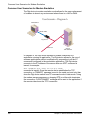
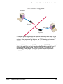
Common User Scenarios for Modem Emulation ............................... 264
Connection Scenarios for Modem Emulation .................................... 266
About the Commands in this Chapter................................................ 266
Accepted But Ignored AT Commands ............................................... 266
Modem Emulation AT Command Set ................................................ 267
S-Register Definitions........................................................................ 269
Result Codes ..................................................................................... 271
Index....................................................................................................... 273
Contents
5
6
Contents
Devices in the Digi One and PortServer TS Family
C o m m a n d L i n e C o n f i g u r a t i o n Ta s k s
Chapter 1
This chapter shows how to perform common device configuration tasks
from the command line.
Devices in the Digi One and PortServer TS Family
This manual uses “the Digi One and PortServer TS Family” to refer to all
devices in the family, and family names to refer to a group of devices. For
example, the command summaries in this chapter and the device-support
information for each command description.
Devices and family names included in the Digi One and PortServer TS
Family are:
Digi One Family
The Digi One Family of devices includes:
• Digi One SP
• Digi One SP IA
• Digi One IA
• Digi One IAP
PortServer TS Family
The term “PortServer TS Family” is used to refer to all PortServer TS
devices. Within this family are two major groupings of devices with different
firmware:
• PortServer TS Family (RS-232 only) devices
• PortServer TS MEI devices
PortServer TS Family (RS-232 only) Devices
The term “PortServer TS Family (RS-232 only) devices” refers to the
following device families:
PortServer TS 1/2/4 Family:
•
•
•
PortServer TS 1, formerly known as Digi One RealPort
PortServer TS 2
PortServer TS 4
PortServer TS 8/16 Family:
•
•
•
•
•
•
Chapter 1
PortServer TS 8
PortServer TS 8 DC
PortServer TS 16
PortServer TS 16 Rack
PortServer TS 16 Rack DC
PortServer TS 16 Enterprise
Command Line Configuration Tasks
7
Devices in the Digi One and PortServer TS Family
PortServer TS MEI devices
The term “PortServer TS MEI devices” refers to the following device
families:
PortServer TS MEI Family:
•
•
PortServer TS 1 MEI, formerly known as Digi One TS
PortServer TS 2 MEI
•
PortServer TS 4 MEI
PortServer TS H MEI Hardened Family:
•
•
•
PortServer TS 1 H MEI
PortServer TS 2 H MEI
PortServer TS 4 H MEI
•
PortServer TS 1 Hcc MEI
•
PortServer TS 2 Hcc MEI
•
PortServer TS 4 Hcc MEI
PortServer TS M MEI Modem Family:
•
•
PortServer TS 1 M MEI
PortServer TS 3 M MEI
PortServer TS P MEI Power Family:
•
•
•
PortServer TS 1 P MEI
PortServer TS 2 P MEI
PortServer TS 4 P MEI
PortServer TS W MEI Wireless Family:
•
•
•
PortServer TS 1 W MEI
PortServer TS 2 W MEI
PortServer TS 4 W MEI
PortServer TS 8/16 MEI Family:
•
•
8
PortServer TS 8 MEI
PortServer TS 16 MEI
Chapter 1 Command Line Configuration Tasks
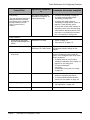
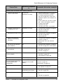
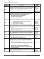
Quick Reference for Configuring Features
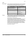
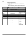
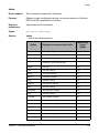
Quick Reference for Configuring Features
The following table shows common features that can be configured, the
Digi devices in which the features are supported, the commands used to
configure each feature, and where to find more information in this chapter.
Feature/Task
Autoconnection
Digi Devices supported
in
Commands, discussion, examples
All
• "Configure Autoconnection" on page 23
• "set ports" on page 169
• "set user" on page 230
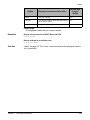
• Backup/Restore
configuration
All
• "cpconf" on page 58
• Upgrade firmware
All
"Upgrade Firmware" on page 45
• Copy configuration to and
from a remote host
All
• "Copy the Configuration to and from a
Remote Host (Backup/Restore)" on page
45
• "cpconf" on page 58
• Reset configuration to
defaults
All
• "Reset the Configuration to Defaults" on
page 45
• "revert" on page 79
Configuration management:
or:
• "boot" on page 51 (boot action=factory)
Domain Name Server (DNS)
All
• "Configure Domain Name System
(DNS)" on page 32
• "set config" on page 97
• "set host" on page 124
Embedded Modem
PortServer TS M MEI Family
• "Configure Embedded Modem" on page
44
• "set embmodem" on page 108
• "set ports" on page 169 (set ports - dev
option, where dev=min, mout, or mio)
Chapter 1
Command Line Configuration Tasks
9
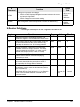
Quick Reference for Configuring Features
Feature/Task
Digi Devices supported
in
Commands, discussion, examples
Industrial Automation (IA):
• Protocol conversion
between Modbus, AllenBradley, and ASCII device
Digi One IAP
• Allen-Bradley Ethernet-toSerial Bridging
Digi One IAP
• Omron Hostlink Multi-Master
Digi One IAP
• Modbus Ethernet-to-Serial
Bridging
Digi One IA
Digi One IAP
PortServer TS Family
• Custom (user-defined)
Multi-Master Protocol
Digi One IAP
PortServer TS Family
IP routing
All
•
•
•
•
MEI
PortServer TS 8/16 ME
Family
• "set mei" on page 158
• "set switches" on page 210
Modem emulation
Digi One SP
Digi One IA
PortServer TS Family
• "Configure Modem Emulation" on page
22
• "set pmodem" on page 168
• "set ports" on page 169--dev=pm option
• AT commands: See Chapter 3, "Modem
Emulation Commands"
Point-to-Point Protocol (PPP)
connections
PortServer TS Family
• "Configure PPP Connections" on page
17
• "set ports" on page 169
• "set flow" on page 116
• "set user" on page 230
• "set filter" on page 111
• "set route" on page 185
• "set forwarding" on page 120
• "set device" on page 104
• "set ippool" on page 146
Port buffering
PortServer TS Family
• "display buffers" on page 61
• "set buffer" on page 93
Port logging
Digi One IAP
PortServer TS Family
• "Configure Port Logging" on page 27
• "set logport" on page 155
Port profiles
All devices that support the
default Web user interface
• "set profiles" on page 178
10
• "Configure Industrial Automation (IA)" on
page 22
• "set ia" on page 125
• For additional information on configuring
Industrial Automation, see this web site:
http://www.digi.com/applications/
industrialautomation/index.jsp
"Configure IP Routing" on page 28
"set route" on page 185
"set forwarding" on page 120
"set user" on page 230
Chapter 1 Command Line Configuration Tasks
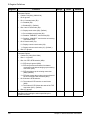
Quick Reference for Configuring Features
Feature/Task
Digi Devices supported
in
Commands, discussion, examples
All; console menu feature
available on PortServer TS
Family devices only.
• "Configure Port Sharing" on page 24
• To configure port-sharing options:
"set sharing" on page 198
• To display port-sharing options:
"set sharing" on page 198“or "show" on
page 251 (“show sharing” option
• To set up the console menu options, for
displaying current users, disconnecting
other sessions, displaying entries in the
port buffer, or accessing the command
line: "set consmenu" on page 102.
• Power through Integrated
Remote Power Management
(RPM)
PortServer TS Family
• "power" on page 72
• "set powerunit" on page 175
• Power Over Ethernet (POE)
Digi One IAP
PortServer TS P MEI Family
This is a hardware feature. There are no
configurable software settings for this
feature.
• Power Over Ports/Power
Over Serial
PortServer TS P MEI Family
This is a hardware feature. Enabling it
involves changing a jumper inside the
device. See "Configure Power Over Serial
Ports" on page 43
• To display status of circuit breaker:
“display circuitbreaker” (See "display" on
page 59) or “set config print”
• To reset circuitbreaker:
“set config
circuitbreaker=reset” (See "set config"
on page 97)
RealPort
All
• See also the RealPort Setup Guides for
details on configuring this feature.
• To configure RealPort authentication
options, see "set rpauth" on page 187.
Remote login (rlogin)
All
• "rlogin" on page 83
• "set rloginoption" on page 184
Revert configuration settings
All
"revert" on page 79
Port sharing
This is an advanced serial-port
setting that allows more than
one client to open a serial port
through RealPort, reverse
Telnet, reverse SSH, or
connect.
Power Features:
Chapter 1
Command Line Configuration Tasks
11
Quick Reference for Configuring Features
Feature/Task
Digi Devices supported
in
Commands, discussion, examples
Security, users, and access control features:
• Control user access to
configuration settings
All
• "Control Access to the Configuration" on
page 35
• "set user" on page 230
• Control user access to
inbound and outbound ports
All
• "Control Access to Inbound Ports" on
page 36
• "Control Access to Outbound Ports" on
page 37
• "set ports" on page 169 - "dev" option
• "set logins" on page 152
• "set user" on page 230
• Control user access to the
command line
All
• "Control User Access to the Command
Line" on page 37
• Through autoconnect by port: "set ports"
on page 169
• Through autoconnect by user: "set user"
on page 230
• Through menus: "set menu" on page
159
• Restrict access to outbound
ports
All
• "Restrict Access to Outbound Ports" on
page 37
• "set auth" on page 90
• Use CHAP authentication for
PPP users
All
• "Use CHAP Authentication for PPP
Users" on page 37
• "set user" on page 230
• Use RADIUS to authenticate
users
PortServer TS Family
• "Use RADIUS to Authenticate Users" on
page 38
• "set radius" on page 181
• "set filter" on page 111
• Issue user passwords
All
• "Issue User Passwords" on page 40
• To enable/disable password for a user:
"set user" on page 230
• To issue new password to user:
"newpass" on page 69
• "Configure User Attributes" on page 43
12
Chapter 1 Command Line Configuration Tasks
Quick Reference for Configuring Features
Feature/Task
Digi Devices supported
in
Commands, discussion, examples
Security, users, and access control features (continued):
• Configure SSH Version 2 for
secure communication
Digi One IAP
PortServer TS Family
• "Configure SSH Version 2 Encryption for
Secure Communication" on page 41
• To configure password protection:
"set user" on page 230 - "name" and
"password" options, and "newpass" on
page 69
• To use a public key: "set user" on page
230 - "name" and "loadkey" options
• To make reverse SSH
connections to ports:
“ssh base_port+ 500 + port_number”
• Configure a custom menu to
be displayed to a user
PortServer TS Family
• "Configure User Attributes" on page 43
• "set user" on page 230 “defaultaccess=menu”
• Automatically connect a user
All
• "Configure User Attributes" on page 43
• "set user" on page 230 "autoconnect=on"
• Delete a user definition
(Remove a user from the
user table)
All
• "Configure User Attributes" on page 43
• "remove" on page 77
• Note that the “root” user cannot be
deleted.
• Set common user features
(user attributes)
All
• "Configure User Attributes" on page 43
• "set user" on page 230 - "name" option
• Use a RADIUS server to set
user attributes
PortServer TS Family
• "Configure User Attributes" on page 43
• "set radius" on page 181
• "set filter" on page 111
Simple Network Management
Protocol (SNMP)
All
• "Configure SNMP" on page 33
• "set snmp" on page 201
• "set snmpauth" on page 204
TCP Socket Communication
All
"set tcpip" on page 214
Time-related features,
including Simple Network Time
Protocol (SNTP) client
configuration
PortServer TS 8/16 Family
PortServer TS 8/16 MEI
Family
"set sntp" on page 206
"set time" on page 221
"set timezone" on page 222
UDP Multicast Communication
All
• "set udpdest" on page 225
• "set udpserial" on page 227
Web interface
All devices that support the
default Web user interface
• "set netport" on page 167
• "set web" on page 243
Wireless devices
PortServer TS W MEI Family
• "Configure Wireless Devices" on page
27
• "set wlan" on page 244
Chapter 1
Command Line Configuration Tasks
13
Access the Command Line
Access the Command Line
To configure devices using commands, you must first access the command
line, either from a locally connected terminal or a Telnet session, and then
log on as root from the command line.
From a Locally-Connected Terminal
To access the command line and the configuration from a terminal
connected to one of the device server’s serial ports, follow these steps.
1. Connect a terminal or PC to a serial port on the device server. For a
Windows HyperTerminal connection, use the cable that came in the
package.
2. Configure the options of the terminal or terminal emulation software to
work with the Digi serial port. The default port settings are:
• VT 100 emulation
• 9600 baud
• 8-bit character
• 1 stop bit
• No parity
3. Log on as the “root” user. The default password is “dbps.”
From a Telnet Session
Use this procedure to access the command line and the configuration from
a Telnet session. This procedure assumes that you have configure the Digi
device with an IP address already. See "Configure an IP Address" on page
16.
1. To Telnet to the device server, enter the following command from a
command prompt on another networked device, such as a server:
#> telnet ip address
where ip address is the device server’s IP address. For example:
#> telnet 192.3.23.5
2. Log on as the “root” user. The default password is “dbps.”
If You Cannot Access the Command Line
If you cannot access the command line, your user access permissions may
be set to disable access to the command line. See "Control User Access to
the Command Line" on page 37.
14
Chapter 1 Command Line Configuration Tasks
Users and User Permissions
Users and User Permissions
Digi One and PortServer TS products have two types of users, with
different user permissions that influence the commands that the users can
issue.
The “root” User
A “root” user exists in all products. This root user has permissions to
execute all commands, except “admin,” which is used to give a normal user
temporary administrative privileges. The root user can configure settings
as well as display current settings. This root user definition cannot be
changed or deleted.
“Normal” Users
You can define additional users for your Digi products using the “set user”
command, known as “normal” or “customer-defined” users. These users
have limited user permissions for executing commands that cannot be
altered.
“Required Permissions” Statements in Command Descriptions
Each command description has a “Required permissions” statement that
defines which users can use the command, and how they can use it. For
example:
• “Root privileges are required to use this command” means that only the
root user can issue the command.
• “Anyone can use this command” means that root and normal users can
issue the command.
• For “set” commands that configure features, the root user can issue
commands to configure the features, but normal users can display
current settings for the feature only.
Increasing Security for Digi Device Users
As needed, you can enforce additional security for device users by either of
these methods:
• Custom menus: You can create a custom menu displayed to device
users at login that offers a limited subset of commands. The “set menu”
command is used to create custom menus. See "set menu" on page
159.
• Using the autoconnect feature, where after login the user is
automatically connected to another system without accessing the Digi
device’s command line and password requirements. You can configure
autoconnection by port or by user. See "Configure Autoconnection" on
page 23.
Chapter 1
Command Line Configuration Tasks
15
Configure RealPort
Configure RealPort
RealPort is a feature that allows network-based host systems to use the
ports of the device server as though they were the host system’s own ports,
appearing and behaving as local ports to the network-based host.
The “set rpauth” sets authentication options for RealPort. RealPort has a
challenge-authentication protocol that, if enabled, allows only hosts that
authenticate to use ports on the Digi device. This authentication protocol is
supported for both encrypted and unencrypted versions of RealPort.
In order to use RealPort authentication, it must be enabled in both the
driver and the Digi device.
For further configuration details, see "set rpauth" on page 187 and the Digi
One and PortServer TS Family User Guide’s chapter on setting up
RealPort.
Configure an IP Address
To configure an IP address, mask, and default gateway for the device
server’s Ethernet interface, use the “set config” command.
1. To ensure that the IP address you configure is permanent, turn DHCP
off by entering:
#> set config dhcp=off
2. Configure an IP address for the Ethernet interface by entering:
#> set config ip=ip address
where ip address is the IP address for the Ethernet interface. For
example:
#> set config ip=191.143.2.154
3. Configure a subnet mask by entering:
#> set config submask=mask
where mask is the subnet mask for this subnetwork. For example:
#> set config submask=255.255.255.0
4. To configure a default gateway, enter:
#> set config gateway=ip address
where ip address is the IP address of the default gateway. For example:
#> set config gateway=191.143.2.46
5. Reboot the Digi device at the prompt by entering:
#> boot action=reset
For more information, see "set config" on page 97 and "boot" on page 51.
Example
The two “set config” commands configure the Ethernet interface. The
“boot” command reboots the Digi device, which is required for the address
change to take effect.
#> set config ip=192.150.150.10 submask=255.255.255.0 dhcp=off
#> set config gateway=192.150.150.11
#> boot action=reset
16
Chapter 1 Command Line Configuration Tasks
Configure Serial Port Settings
Configure Serial Port Settings
Configuring serial port settings involves setting the following options for a
port:
• Point-to-Point (PPP) connections
• Industrial automation (IA)
• Modem emulation
• TCP socket communication
• UDP Multicast communication
• Autoconnection
• Port sharing
Configure PPP Connections
Configuring Point-to-Point Protocol (PPP) connections includes:
• Configuring inbound PPP connections
• Configuring outbound PPP connections
• Using filters on the PPP connections, as needed
Configure Inbound PPP Connections
To configure simple inbound PPP connections from the command line,
follow the steps below. Regarding inbound PPP connections:
• For information on fine-tuning PPP connections, see "set user" on page
230.
• CHAP authentication works between two Digi devices. CHAP will be
negotiated to PAP for all other connections
1. To configure the port for a modem, enter:
#> set ports range=range dev=device
where range is the port or ports and device is “min” for inbound-only
modem connections, or “mio” for bidirectional modem connections.
For example:
#> set ports range=3 device=min
2. To configure flow control for the ports, enter:
#> set flow range=range flow control scheme
where range is the port or ports and flow control scheme is the flow
control required for this connection.
There are several options for establishing a flow-control scheme on
“set flow.” Typically, for modem connections, RTS and CTS are on. The
following example shows a typical flow-control scheme for a modem:
#> set flow range=3 ixon=off ixoff=off rts=on cts=on
Chapter 1
Command Line Configuration Tasks
17
Configure Serial Port Settings
3. To configure the baud rate for this connection, enter:
#> set line range=range baud=bps
where range is the port or ports to configure and bps is the line speed in
bits-per-second. Typically, you can set this to 115000 bps for modem
connections. For example:
#> set line range=3 baud=115000
4. To create an inbound PPP user, enter:
#> set user name=name protocol=ppp netservice=on defaultaccess=netservice
where name is a name to assign to the PPP user. For example:
#> set user name=pppin protocol=ppp netservice=on defaultaccess=netservice
5. To configure an IP address for the remote PPP user, enter:
#> set user name=name ipaddr=ip address
where name is the user’s name, and ip address is one of the following:
• A standard IP address in dotted decimal format.
• 0.0.0.0, which means the remote user will supply the IP address.
• The keyword “ippool,” which means the user will be assigned an IP
address from an IP address pool. See "set ippool" on page 146.
For example:
#> set user name=pppin ipaddr=ippool
6. If you used the IP address pool option in the previous step, specify the
following subnetwork mask (a mask of 255.255.255.255 is required) by
entering:
#> set user ipmask=255.255.255.255
7. To configure an IP address for the local end of the PPP connection,
enter:
#> set user name=name localipaddr=ip address
where name is the user’s name and ip address is the IP address to
assign to the local end of the PPP connection. This address must be
unique. That is, no other user can be assigned this address and it
cannot be the IP address for the Ethernet interface. For example:
#> set user name=pppin localipadr=199.1.1.2
Example
This example shows a very simple PPP inbound configuration where:
• The port is set up for inbound connections (dev=min).
• RTS and CTS are used for flow control.
• The baud rate has been set to 115000 bps.
• The user has been configured to use an IP address pool.
#> set ports range=3 device=min
#> set flow range=3 ixon=off ixoff=off rts=on cts=on
#> set line range=3 baud=115000
#> set user name=pppin protocol=ppp netservice=on defaultaccess=netservice
#> set user name=pppin ipaddr=ippool
#> set user name=pppin localipadr=199.1.1.2
18
Chapter 1 Command Line Configuration Tasks
Configure Serial Port Settings
See also
For more information, see these command descriptions:
• "set ports" on page 169
• "set flow" on page 116
• "set line" on page 149
• "set user" on page 230
Configure Outbound PPP Connections with Filters
To configure outbound-only PPP connections with filters, or the outbound
portion of bidirectional connections with filters, follow the steps below.
Regarding outbound PPP connections:
• If you do not require filters for your outbound PPP connection, you may
use this procedure, but omit step 1. If there is no filter, when the dialout
connection is turned on, the device will automatically dial out.
• For dialout outbound connections to a non-Digi device, select a PPP
authentication type of none, using the “set user” option “pppauth=none.”
CHAP authentication works between two Digi devices.
• If you change a filter type after an initial configuration, existing PPP
sessions must be terminated and reestablished For the new filter
settings to take effect.
1. To set the filter for the outbound connection, enter:
#> set filter name=”filter name” s1=dst/ip address/subnetmask
See "set filter" on page 111 for more details on filters.
2. To set the flow control to hardware, enter:
#> set flow range=1 ixon=off ixoff=off rts=on cts=on
Note:
PortServer TS 1/3+Modem flow control default is Hardware.
3. To configure the user for the outbound PPP connection, enter:
#> set user name=”<username>” protocol=ppp
4. To set up the user for the PPP environment, including such items as the
local IP address, the devices, and telephone number, enter:
#> set user name=”<username>” ipaddr=negotiated ipmask=255.255.255.255
For a description of the options for specifying the IP address, see
"ipaddr=ip addr" on page 236 of the “set user” command description.
#> set user name=”username” defaultaccess=netservice autoport=513
password=on
#> set user name=”username” outgoing=on autoservice=default
#> set user name=”username” bringup=”filter name”
#> set user name=”username” device=”gendialer”
5. To assign the dialscript to which the port the modem is connected,
enter:
#> set device name=”gendialer” baud=no dialer=genmdm chat=no port=1
For more information on the configuring the port, see "set device" on
page 104.
Chapter 1
Command Line Configuration Tasks
19
Configure Serial Port Settings
6. To set up routing for the PPP connection, enter:
#> set forwarding state=active splithorizon=off poisonreverse=off
#> set route net=ip address mask=subnetmask metric=1 wanname=”username”
The value of the “wanname” option must match the value of the
“username” option in step 2.
7. To enable the new wan interface, enter:
#> set user name=”username” dialout=on
Example
The following example shows a simple outbound PPP configuration with
filters and the following properties:
• The port is set up for outbound connections.
• Flow control is set to Hardware (for the PortServer TS 1/3+Modem, the
default is Hardware).
• Default device and scripts are used.
#> set filter name=”filter name” s1=dst/ip address/subnetmask
#> set flow range=1 ixon=off ixoff=off rts=on cts=on
#> set user name=”username” protocol=ppp
#> set user name=”username” ipaddr=negotiated ipmask=255.255.255.255
#> set user name=”username” defaultaccess=netservice autoport=513 password=on
#> set user name=”username” outgoing=on autoservice=default
#> set user name=”username” bringup=”<filter name>”
#> set user name=”username” device=”gendialer”
#> set device name=”gendialer” baud=no dialer=genmdm chat=no port=1
#> set forwarding state=active splithorizon=off poisonreverse=off
#> set route net=ip address mask=subnetmask metric=1 wanname=”username”
#> set user name=”username” dialout=on
20
Chapter 1 Command Line Configuration Tasks
Configure Serial Port Settings
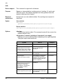
Filters for PPP Connections
Filters are used to manage and control Point-to-Point Protocol (PPP)
connections. You can design a filter to do any of the following:
• Bring up a connection.
• Allow certain types of packets to use the connection and keep certain
types of packets from using it.
•
•
Keep up a connection.
Send a message to the log file when a specified event occurs on the
connection.
For example, you might develop a filter that brings up a connection on an
outbound port only when device server handles a packet carrying a
particular destination IP address.
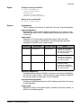
The “set user” command has options that define how a filter functions, that
is, whether it is the type of filter that accepts or blocks packets, brings up a
connection, keeps up a connection, or sends a message to the log file. The
following table describes each of the set user options related to filtering.
“set user”
Option
Description
Example
passpacket
Causes a packet to be
passed or blocked.
Filter causes incoming packets from
an IP address to be accepted and
packets from all other IP addresses
to be blocked.
keepup
Causes the idletimeout
timer to be reset and a
connection maintained.
Filter that causes the connection to
be maintained as long as there is
any packet traffic except RIP
packets.
bringup
Causes the Digi device to
establish a connection.
Filter that causes an outgoing
connection to be initiated whenever
a packet specifying a particular IP
address is handled.
logpacket
Causes the Digi device to
send a message to the
log file.
Filter that notifies the log anytime an
ICMP packet is handled.
When changes to filter definition settings take effect
The “set filter” command can be used at any time to change and display
filters. However, the results of any changes to filter definition settings take
effect on subsequent PPP connections only. Any PPP connections
established prior to a given filter change will continue to operate using the
previous filter definition settings. For the new filter settings to take effect,
existing PPP sessions must be terminated and reestablished.
More information on filters
For more information about using filters, see "set filter" on page 111, and
"set user" on page 230.
Chapter 1
Command Line Configuration Tasks
21
Configure Serial Port Settings
Configure Industrial Automation (IA)
To configure how devices in an industrial automation (IA) environment
communicate, use the “set ia” command.
See "set ia" on page 125 for command syntax, option descriptions, and
examples. The syntax for “set ia” varies according to the IA device being
configured: serial port-connected devices, network-based masters,
network-based slaves, and destination tables for forwarding messages.
The “set ia” command description shows these syntax variations, the
effects of the command options for each variation, and examples of
configuring several IA devices.
Protocols for IA Devices
IA devices can use various communication protocols, including Modbus
variations (Modbus/RTU, Modbus/ASCII, and Modbus/TCP), AB/DF1 FullDuplex and AB/DF1 Half-Duplex, Hostlink, AB/Ethernet (CSP), Ethernet/IP,
and a Custom (or “user-defined”) protocol.
Recommendations on Configuring Industrial Automation
Due to the flexibility involved, manual configuration of IA scenarios by
command line is recommended for advanced users only. New users are
encouraged to use the Industrial Automation Wizard under the Applications
section of the Web Browser interface.
Where to find more information on Industrial Automation
Besides the “set ia” command description, additional information on
configuring Industrial Automation is available at the following URL:
http://www.digi.com/applications/industrialautomation/index.jsp
Configure Modem Emulation
Modem emulation enables a system administrator to configure a
networked Digi device server to act as a modem.
See Chapter 3, "Modem Emulation Commands" for more information on
modem emulation.
Configure TCP Socket Communication
Transmission Control Protocol (TCP) socket communication enables serial
devices to communicate with each other over an Ethernet network as
though they were connected by a serial cable.
To configure TCP socket communications, use the “sockets” option on the
“set config” command. See "set config" on page 97.
Configure UDP Multicast Communications
User Datagram Protocol (UDP) multicast is used to send serial data over
an Ethernet cable to one or many hosts at the same time.
To configure UDP multicast communications, use the “set udpdest”
command. See "set udpdest" on page 225.
22
Chapter 1 Command Line Configuration Tasks
Configure Serial Port Settings
Configure Autoconnection
The autoconnection feature allows you to configure a user to access the
device server and then be automatically connected to a host on the LAN.
You can implement autoconnection in the following ways:
• By port, where all port users are automatically connected to the same
host. The device server is completely transparent to them.
•
By user, where a user is required to log on and may be required to
supply a password. Once the user is authenticated, an automatic
connection to a host is made.
To configure autoconnection, either by port or by user, use the following
commands:
• “set ports,” specifying the “auto,” “autoservice,” “dest,” “dev,” and “dport”
options. See "set ports" on page 169.
• “set user,” specifying the “name,” “autoconnect,” “autohost,” “autoport,”
and “defaultaccess” options. See "set user" on page 230.
Examples
Configure an autoconnect port
In this example, “set ports” configures the port so that all incoming users
are automatically connected via Telnet to the host specified on the “dest”
option. The port is also available for outgoing connections.
set ports range=1 auto=on dest=199.125.123.10 dev=mio dport=23
Configure an autoconnect user
In this example, “set user” configures user4 to be automatically connected
via Telnet to a host at address 199.193.150.10.
#> set user name=user4 autoconnect=on autohost=199.193.150.10 autoport=23
defaultaccess=autoconnect
Chapter 1
Command Line Configuration Tasks
23
Configure Serial Port Settings
Configure Port Sharing
A Digi device enabled for port sharing allows more than one client to open
a port through RealPort, reverse Telnet, reverse SSH, or connect. All
clients that share a port will read the same data from the serial port; the
data is duplicated and sent to each client. All clients that share a port will
have the data they write merged and sent out the serial port. The serial port
options, such as baud rate and flow control, can either be shared by all
clients or be controlled exclusively from the Digi device alone. If there is
only one client, then RealPort, reverse Telnet, reverse SSH, and connect
will work normally.
Device types that allow port sharing
Port sharing is only available for device types “rp,” “prn,” and “mout,” as
specified by the “set ports dev=device” option.
Configuring port sharing
Configuring port sharing involves specifying how many clients are allowed
to share the port, whether control should be shared by all clients or
controlled exclusively by the Digi device, and the flow control timeout.
These options can be configured independently for each port. The
command for configuring port sharing is set sharing (see "set sharing" on
page 198).
Configuring a console menu for use with port sharing
The Console Menu feature of the Digi PortServer TS allows you to see who
is already connected to a port, disconnect other sessions, display the last
entries of the port-buffer or branch out to the command line of the unit. The
console menu is configured using the “set consmenu” command. See
"set consmenu" on page 102.
Displaying port-sharing settings
Port-sharing settings are displayed by either of the following commands:
• “set sharing” - display variation (see "set sharing" on page 198)
• “show” - display variation (see "display" on page 59)
The port-sharing settings are displayed in four columns: “current clients,”
“max clients,” “control,” and “timeout.”
The “current clients” column shows how many clients are currently sharing
the port. The “max clients,” “control,” and “timeout” columns show the value
set with the “clients,” “control,” and “timeout” options.
24
Chapter 1 Command Line Configuration Tasks
Configure Serial Port Settings
When changes to port-sharing settings take effect
Some changes will not take effect until all clients have closed a port. If this
is the case, the “set sharing” command will print a warning message
saying:
“Warning: Some port sharing parameter changes will not take effect until all
clients have closed the port.”
Some changes take effect immediately, for example, changing the control,
changing the timeout value, or increasing the maximum number of clients
clients if the “clients” option is already larger than 1 (so that port sharing is
already on).
About flow control on shared ports
All open shared ports share the same underlying input data buffers, so they
must remain roughly in sync in the input data stream. For example, if one
client stops reading data, the other clients sharing that same physical port
can only read one buffer full of data ahead before they must wait for the
first client to catch up.
To overcome this limitation that all clients must remain roughly in sync
when reading data, a user-configurable timeout can be set by the
“set sharing timeout” option. If one client is waiting for the other clients to
read, it only has to wait until the timeout expires and then it will be allowed
to continue reading. The other clients, that is, ones that are not reading
data, will lose data from the time the timeout expires until they begin
reading again. This timeout will not be set by default.
Considerations and cautions for port sharing
There are several caveats when using port sharing:
• When clients send data to the ports, their data will be intermixed; that is,
there is no synchronization of the data. If two clients send data at the
same time, the data from one client might appear in the middle of the
other client's data.
• If one client stops reading data, the input will be flow-controlled for all
clients. Clients will only be able to read data at the rate of the slowest
client. (There is a timeout to override this, as described above.)
• Incoming opens, persistent opens, and immediate opens may not
behave as expected when multiple clients are opening the port at the
same time.
• The modem control lines are not dropped until all clients have closed
the port.
• When multiple clients share control of the serial port options, such as
baud rate, data size, parity, flow control, etc., the last options set will
take effect. The serial port options could be changed unexpectedly by
another client. This could leave the RealPort driver confused about the
correct serial port settings. Different RealPort drivers might react
differently to these unexpected changes in serial port settings.
Chapter 1
Command Line Configuration Tasks
25
Configure Serial Port Settings
•
•
•
•
•
When multiple clients share control of the serial port options, and a new
client opens a port, that new client might momentarily set the options to
default values before the application can set the options correctly. This
might momentarily disrupt communication with the other clients.
Depending on the operating system used by the client, it is possible to
set the default serial port options to match the options required by the
application. Then, there will be no disruption.
When multiple clients share control of the serial-port options, some
serial-port options, such as case conversion, carriage return, newline
mapping, etc., might be handled on the client system. Therefore, these
options would apply to the client that set these options only.
When the Digi device exclusively controls the serial port settings, any
attempt to change the serial port settings from a client will be silently
ignored. The client will believe the settings have been changed, when in
fact they have not. The only way to change the serial port settings is
through the command line on the Digi device or through the web UI.
With reverse Telnet, reverse SSH, and connect, it is possible for a
single client machine to open a single shared port multiple times by
using multiple telnet or ssh sessions.
However, with RealPort, it is not possible for a single client machine to
open the same RealPort multiple times and use port sharing. Windows
simply prevents one machine from opening a RealPort more than once.
Unix does allow a single machine to open a RealPort more than once,
but the sharing is happening on that Unix machine, not on the Digi
device.
Unix sharing does merge data written to the port and shares control of
the port. However, it does not duplicate the incoming data to all
programs that have opened the same RealPort. Instead, the incoming
data is arbitrarily divided among the programs.
It is possible for one machine to use port sharing with RealPort, but only
by configuring the RealPort driver multiple times for the same Digi
device.
Windows RealPort explicitly forces DTR and RTS to drop when it closes
a port. This could prevent other clients sharing that port from sending or
receiving data, depending on the configuration. If this is a problem, set
the shared port for exclusive control. Unix RealPort does not have this
problem.
Examples
The example "Display and change port-sharing settings" on page 199
shows how to use the “show sharing” and “set sharing” commands to
display current port-sharing settings, configure port-sharing settings, and
display the changed settings.
26
Chapter 1 Command Line Configuration Tasks
Configure Port Logging
Configure Port Logging
The port logging feature passively logs data going into or out of a serial
port. This means that you can be using a standard reverse or RealPort
session on a port, and all the data from that session can be sent to a
configurable server.
To configure port logging, use “set logport” command. See "set logport" on
page 155.
To revert the port-logging settings to defaults or to the latest configuration
stored in NVRAM, use the “revert logport” command. See "revert" on page
79.
Configure Wireless Devices
To configure wireless devices, use the “set wlan” command. See "set wlan"
on page 244. Configuring a wireless device involves specifying:
• The authentication used for the device.
• Whether the device automatically detects available Set Service
Identifiers (SSIDs).
• The country code for the device’s radio.
• The number of access points in the vicinity.
• The antenna choice for transmit and receive.
• Whether the device uses encryption, and if so, which kind.
• The encryption key, if encryption is used.
• The fragmentation boundary for directed messages.
• The number of bytes used for the RTS/CTS handshake.
• The desired SSID for the device.
Example
#> set wlan ssid=”homeBase” encryption_mode=128
encryption_key=ab1F793f01578ebf567afeb567
#> set wlan ssid=”homeBase” em=128 ek=ab1F793f01578ebf567afeb567
Chapter 1
Command Line Configuration Tasks
27
Configure Network Settings
Configure Network Settings
Configuring network settings involves setting network parameters,
configuring IP routing, setting up a Domain Name Server (DNS). and
setting up Simple Network Management Protocol (SNMP).
Configure Network Parameters
The "set config" command configures network parameter, and includes
several options for optimizing your network for better Ethernet/IP
performance. See "set config" on page 97.
The "set ethernet" command sets Ethernet options. See "set ethernet" on
page 109.
Configure IP Routing
Configuring IP routing involves these tasks:
• Configure static routes using the “set route” command (see "set route"
on page 185).
• Configure dynamic routes using the “set forwarding” command (see
"set forwarding" on page 120).
• Configure Proxy ARP using the “set forwarding” command.
Configure Static Routes
To configure a static route over a PPP link, enter:
set route net=addr mask=mask metric=hops wanname=interface
gateway=gateway
where:
• “net” is either the IP address of a system to be reached over this route
or the network address of the subnet that is to be reached on this route.
• “mask” is the mask to use for interpreting the IP address.
• “metric” is the number of hops to the destination.
• “wanname” is the interface to use for this route.
For routes over a PPP link, use the name of a PPP user that was
defined in a previously issued “set user” command, for example “ppp1”
or “link1.” (See "set user" on page 230 for information on and options
for defining PPP users.)
For routes over the Ethernet interface, use “ether.”
• “gateway” is the IP address of the device that is the next hop to the
destination. If there is no next hop destination, set the gateway to the
device IP address.
For more information on static routes, see "set route" on page 185.
28
Chapter 1 Command Line Configuration Tasks
Configure Network Settings
Example: Route Using the Ethernet Interface
In this example, a route to a subnet is created over the Ethernet interface.
Key features include the following:
• The address on the “net” option is a subnetwork address, not the IP
address of a specific device.
• The “wanname=ether” option, indicating that this route is over the
Ethernet interface.
• The “metric” option indicates that packets to this subnet will pass
through two routers.
• The “gateway” option indicates that all packets using this route are to be
forwarded to the device at IP address 191.21.21.2.
#> set route net=199.21.33.0 mask=255.255.255.0 metric=2 wannname=ether
gateway=199.21.21.2
Example: Route Using a PPP Link
In this example, a route to a subnet is created over a PPP interface. Key
features include the following:
• The address on the “net” option is IP address of a specific device, not a
subnetwork address.
• The “wanname” option is the name of a PPP use, indicating that this
route is over a PPP interface.
• The “metric” option indicates that packets to this subnet will pass
through two routers.
• The “gateway” option indicates that all packets using this route are to be
forwarded to the device at IP address 191.21.21.2.
#> set route net=199.21.33.44 mask=255.255.255.255 metric=2 wannname=ppp1
gateway=199.21.21.2
Chapter 1
Command Line Configuration Tasks
29
Configure Network Settings
Configure Dynamic Routes Using RIP
To configure the device server for dynamic routing using the Routing
Information Protocol (RIP), use the “set forwarding” command. See
"set forwarding" on page 120.
You should be signed on as “root” and have configured or will configure
modems, modem scripts, devices, and filters for routes that use serial
lines.
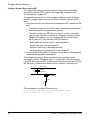
1. Configure the links over which routed packets and RIP updates will be
sent.
• To enable routing over the LAN to which device server is attached,
no routing-specific configuration is required.
• To enable routing over PPP links, be sure to use the “netrouting”
option on the “set user” command to configure how device server
handles RIP updates. You can configure the link so that device
server does any of the following with RIP updates:
- Both sends and receives them (“netrouting=both”)
- Sends them only (“netrouting=send”)
- Receives them only (“netrouting=receive”)
- Neither sends nor receives them (“netrouting=off”)
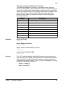
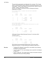
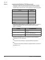
2. Configure the device server for dynamic routing with a “set forwarding”
command that specifies “state=active.”
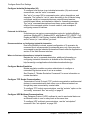
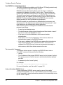
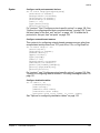
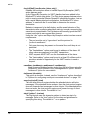
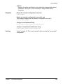
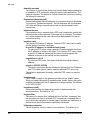
This example shows only those commands and command options
pertinent to routing. The device server is configured for dynamic routing
using RIP. But to prevent RIP updates from being sent across the PPP link,
the “set user” command that defines the link specifies “netrouting=off.”
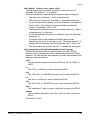
192.150.75.0
Router
187.100.46.9
Digi Device
PPP
The commands to configure this setup are:
#> set forwarding state=active poisonreverse=on splithorizon=on
#> set user name=link1...netrouting=off
30
Chapter 1 Command Line Configuration Tasks
Configure Network Settings
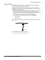
Configure Proxy ARP
To configure the device server for Proxy ARP, use the “set forwarding”
command. See "set forwarding" on page 120.
This procedure assumes that you have signed on as “root” and have
configured or will configure modems, modem scripts, devices, and filters
for routes that use serial lines.
1. Configure the links over which packets will be routed using a “set user”
command. This command must specify (on the “ipaddr” option) a
specific IP address for the remote system using the Proxy ARP service.
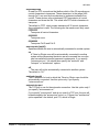
2. Configure the device server for Proxy ARP by supplying a
“set forwarding” command that specifies the following options:
• “state=passive”
• “proxyarp=on”
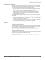
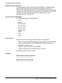
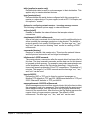
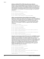
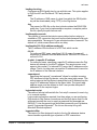
For example, the device server provides Proxy ARP services to a remote
host.
187.155.24.0
Digi Device
PPP
187.155.24.11
The commands to configure this setup are:
#> set user name=link1...ipaddr=187.155.24.11
#> set forwarding state=passive proxyarp=on
Chapter 1
Command Line Configuration Tasks
31
Configure Network Settings
Configure Domain Name System (DNS)
The domain name system (DNS) maps domain names to information
associated with these names, such as IP addresses. Configuring the DNS
involves the following tasks:
• Configure a DNS server
• Configure the host table
DNS components include:
• A distributed database consisting of domain names and associated
information.
• A hierarchical system of domain name servers that maintain the
database and use it to respond to requests for information about a
particular domain name, such as its IP address.
• Domain name resolvers that accept requests from users, satisfy
information requests by building and submitting properly formulated
queries to one or more name servers or by retrieving information from a
local host file, return information to users, and cache information for
future use.
There are two types of name servers in the domain name system. Local
servers maintain information for resources within a local zone. It is up to
individual network administrators to determine the scope of a local zone.
Root servers maintain information in higher-level domains than do local
servers.
Typically, when a user requires information about a domain name, the
resolver queries a local server. If local servers cannot provide the
information, root servers are queried next.
Each node in the domain name system has a globally unique domain name
that consists of its own name, which is called a label, and the labels of all
superior nodes.
Following is an example of a domain name. “mn07” is part of the higherlevel domain called “amalgamated.com.” Note that labels are separated by
periods:
#> mn07.amalgamated.com
Configure a DNS Server
To configure a DNS server, enter:
#> set config domain=domain myname=name dns=ip address
where:
• domain is the domain in which the device server will reside
• name is a DNS name for device server
• ip address is the IP address of a name server
For example:
#> set config domain=digi.com myname=poe dns=204.221.1.4
For more information, see "set config" on page 97.
32
Chapter 1 Command Line Configuration Tasks
Configure Network Settings
Configure the Host Table
To configure the host table, which maps IP addresses to host names, enter:
#> set host name=name ip=ip address
where:
• name is the name the host
• ip address is the IP address of the host
For example, the following commands configure three IP address-to-name
mappings:
#> set host name=poe ip=204.221.110.200
#> set host name=gary ip=204.221.110.202
#> set host name=toni ip=204.221.110.203
For more information, see "set host" on page 124.
Configure SNMP
Simple Network Management Protocol (SNMP) is the network
management protocol that governs the exchange between nodes and
stations.
The TCP/IP network management architecture contains the following
components:
• Managed nodes, such as host systems, routers, terminal and
communications servers (such as device server) and other network
devices.
• One or more network managers (also called network management
stations), which are the points from which the network is managed.
• Agents that reside on managed nodes and retrieve management
information and communicate this information to network managers.
• The network management protocol, SNMP, which governs the
exchange of information between the nodes and stations.
• Management information, which is the database of information about
managed objects. This database is called the management information
base (MIB).
Each managed node contains at least one agent—a component that
responds to requests from the network manager—that retrieves network
management information from its node and notifies the manager when
significant events occur.
A mechanism defined by SNMP is called a trap, which is a report or “alarm”
from a managed node to an SNMP manager that a significant event has
occurred.
Chapter 1
Command Line Configuration Tasks
33
Configure Network Settings
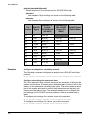
The SNMP management agent supports the following MIBs:
• Read-write for MIB II (RFC 1213), which is an Internet-standard MIB,
consisting of managed objects from the systems, interfaces, IP, ICMP,
TCP, UDP, transmission, and SNMP group
• Read-write for the character-stream devices using SMIv2 MIB (RFC
1658)
•
•
Read-write for the RS-232-like hardware devices MIB (RFC 1659)
Read-write for the device server IP Network Control Protocol of the
Point-to-Point Protocol MIB (RFC 1473)
The SNMP agent supports the “Set,” “Get,” “GetNext,” and “Trap”
messages as defined in RFC 1157. These messages are used as follows:
• “Set,” which means “set the value of a specific object from one of the
supported MIBs.”
• “Get,” which means “retrieve the value of a specific object form one of
the supported MIBs.”
• “GetNext,” which means “retrieve the value of the next object in the
MIB.”
• “Trap,” which means “send traps to the manager when a particular type
of significant event occurs.”
The SNMP agent can generate and send traps to a destination IP address
when any of the following occur:
• Authentication failures
• Login attempts
• Cold starts (when the Digi device initializes)
• Link up (when a network link comes up)
• For Digi devices connected to a Digi RPM power controller, when the
Digi RPM exceeds the current and temperature thresholds.
set snmp Command
To configure SNMP, use the “set snmp” command. For more information,
see "set snmp" on page 201.
For example, the following “set snmp” command configures SNMP with all
trap options:
#> set snmp run=on trap_dest=190.175.178.73 auth_trap=on
cold_start_trap=on link_up_trap=on curr_thresh_exc_trap=on
temp_thresh_exc_trap=on
34
Chapter 1 Command Line Configuration Tasks
Configure Security Features
Configure Security Features
From the command line, you can configure several security-related
features to do the following:
• Control access to the configuration.
• Control access to inbound ports.
• Control access to outbound ports.
• Restrict access to outbound ports.
• Use CHAP authentication for PPP users.
• Control user access to the command line.
• Use RADIUS to authenticate users.
• Issue user passwords.
• Configure SSH Version 2 for secure communication.
Control Access to the Configuration
User access to Digi device configuration settings can be controlled by
either of the following methods:
• Through user attributes configured by various “set user” command
options.
• Through network settings configured by the set user” “network” option.
Controlling access of the device server restricts access to the configuration
by defining the following types of users:
• The “root” user, who has unlimited access to device server commands.
This “root” user can view any configuration table and change any
configuration option. The root is identified by the user name “root” and
must supply a password to be authenticated. The default root password
is “dbps.” You should change this password immediately.
• Regular users, who have much more restricted access to device server
commands. Regular users can view some configuration tables and can
change some configuration options related to their own sessions and
passwords. For information on the limitations placed on regular users
for each command see "set user" on page 230.
Chapter 1
Command Line Configuration Tasks
35
Configure Security Features
Control Access to Inbound Ports
An inbound port is one defined on the “dev” option of the command for one
of the following device types:
• “term” for terminal connections.
• “min” for incoming modem connections.
• “mio” for bi-directional modem connections.
• “hdial” or “hio” for computer connections.
The default configuration for inbound ports is that a login and password are
required to access them.
The login and password requirement for inbound ports can be changed by
configuring either of the following:
• The port, so that it does not require a login and password. In this case,
no one is required to supply a login or password.
• Specific users, so that they do not require a password. In this case,
some users do not supply passwords and others are required.
For more information, see "set ports" on page 169.
Change a Port’s Access Requirements
To configure a port so that no one has to login or specify a password, enter:
#> set logins range=range login=off passwd=off
For example:
#> set logins range=1-2 login=off passwd=off
For more information, see "set logins" on page 152.
Change a User’s Access Requirements
To configure a user so that they do not have to specify a password when
accessing an inbound port, enter:
#> set user name=name password=off
where name is a name to identify the user.
For example:
#> set user name=user1 password=off
For more information, see "set user" on page 230.
36
Chapter 1 Command Line Configuration Tasks
Configure Security Features
Control Access to Outbound Ports
An outbound port is one defined on the “set ports” “dev” option, where
“dev” is set to one of the following device types:
• “prn” for printer connections.
• “mout” for outbound modem connections.
• “mio” for bi-directional modem connections.
• “host” for host connections.
• “ia” for industrial automation devices.
The default for outbound ports is unlimited access.
Restrict Access to Outbound Ports
Use the “set auth” command to restrict access to outbound ports. See
"set auth" on page 90.
Use CHAP Authentication for PPP Users
CHAP authentication can be used to restrict PPP user access to outbound
ports. For more information on CHAP configuration, see "set user" on page
230.
Control User Access to the Command Line
You can restrict user access to the device server command line through the
following methods:
• Using the autoconnection feature
• Using menus
Using the Autoconnection Feature
The autoconnection feature allows you to configure a user to access the
device server but then be automatically connected to a host on the LAN.
You can implement autoconnection in the following ways:
• By port, where all port users are automatically connected to the same
host. The device server is completely transparent to them. Use the
“set ports” command, with the “auto,” “autoservice,” “dest,” “dev,” and
“dport” options. See "set ports" on page 169.
• By user, where a user is required to login and may be required to supply
a password, but once the user is authenticated, an automatic
connection to a host is made. Use the “set user” command, with the
“name,” “autoconnect,” “autohost,” “autoport,” and “defaultaccess”
options. See "set user" on page 230.
Using Menus
Menus select destination systems without having to access the device
server command line. Menus are created using the set menu command.
For information on configuring menus, see "set menu" on page 159.
Chapter 1
Command Line Configuration Tasks
37
Configure Security Features
Use RADIUS to Authenticate Users
The RADIUS feature is available on all PortServer TS Family products only.
It is not supported on Digi One Family devices.
RADIUS (remote authentication dial-in user service) is a method of
maintaining a database of profiles of dial-in users. These profiles can
include login and password information, as well as other user attributes.
The device server can be configured to use RADIUS. Digi device and
terminal servers are capable of authenticating reverse Telnet users with
RADIUS. The Service-Type attribute of the RADIUS server must be
defined correctly for the Digi devices to grant access.
RADIUS requires two components: an authentication host server, and
client protocols. The device server implements the client protocol. A host
must implement the authentication server application.
When a device server is configured for RADIUS, the authentication
process is as follows:
• A user logs into device server.
• The device server collects login information and then checks to see if
the user is in the local database of users.
• If the user is in the local database, device server handles
authentication.
• If the user is not in the local database, device server submits an
authentication request to the RADIUS server.
• If the user is validated, the RADIUS server passes this information to
other devices and the user is permitted access. If the user is not
validated, the RADIUS server returns an access reject message to
device server, which then denies access to the user.
The “set radius” Command
To configure device server to function as a RADIUS client, enter a
“set radius” command that specifies the following:
• run=on
• The IP address of the primary RADIUS server (on the “primary” option).
The primary server is the first server to which authentication requests
are sent.
• A password (on the “secret” option)
For example:
#> set radius run=on primary=199.123.15.129 secret=J9CxegpP
For more information, see "set radius" on page 181.
Using a Secondary RADIUS Server
To use a secondary RADIUS server, supply a second “set radius”
command that specifies “run=on,” the IP address of the secondary server
(on the “secondary” option) and another password for the secondary server
(on the “secret” option).
38
Chapter 1 Command Line Configuration Tasks
Configure Security Features
RADIUS Table Key
The numbers in the following tables have the following meaning:
#
Meaning
0
This attribute must not be present.
0+
Zero or more instances of this attribute may be present.
0-1
Zero or one instance of this attribute may be present.
1
Exactly one instance of this attribute must be present.
RADIUS Attributes (RFC 2138) Supported
The following attributes are supported in the Digi device server RADIUS
client implementation.
Request
Accept
Reject
Challenge
#
Attribute
1
0
0
0
1
User-Name
0-1
0
0
0
2
User-Password
0-1
0
0
0
3
CHAP-Password
0-1
0
0
0
4
NAS-IP-Address
0-1
0
0
0
5
NAS-Port
0-1
0-1
0
0
6
Service-Type
0-1
0-1
0
0
7
Framed-Protocol
0-1
0-1
0
0
8
Framed-IP-Address
0-1
0-1
0
0
9
Framed-IP-Netmask
0
0-1
0
0
10
Framed-Routing
0
0+
0
0
11
Filter-Id
0
0-1
0
0
12
Framed-MTU
0+
0+
0
0
13
Framed Compression
0+
0+
0
0
14
Login-IP-Host
0
0-1
0
0
15
Login-Service
0
0-1
0
0
16
Login-TCP-Port
0
0-1
0
0-1
27
Session-Timeout
0
0-1
0
0-1
28
Idle-Timeout
Chapter 1
Command Line Configuration Tasks
39
Configure Security Features
RADIUS Accounting Attributes (RFC 2139)
The following RADIUS accounting attributes are supported in the Digi
device server.
#
Attribute
#
Attribute
0-1
User-Name
0-1
Login-TCP-Port
0
User-Password
0-1
Session-Timeout
0
CHAP-Password
0-1
Idle-Timeout
0-1
NAS-IP-Address
1
Acct-Status-Type
0-1
NAS-Port
0-1
Acct-Delay-Time
0-1
Service-Type
0-1
Acct-Input-Octets
0-1
Framed-Protocol
0-1
Acct-Output-Octets
0-1
Framed-IP-Address
1
Acct-Session-Id
0-1
Framed-IP-Netmask
0-1
Acct-Authentic
0-1
Framed-Routing
0-1
Acct-Session-Time
0+
Filter-Id
0-1
Acct-Input-Packets
0-1
Framed-MTU
0-1
Acct-Output-Packets
0+
Framed-Compression
0-1
Acct-Terminate-Cause
0+
Login-IP-Host
0-1
Port-Limit
0-1
Login Service
Issue User Passwords
To establish passwords for users, and issue them to users, use the
following commands:
• “set user” with the “password” option to require a password of a user.
See "set user" on page 230.
• “newpass” to create or change a user’s password. See "newpass" on
page 69.
This procedure assumes that you have signed on as “root” and already
used the “set user” command to configure the user to whom you will be
issuing a password.
1. Issue a “newpass” command that identifies the user (on the “name”
option) to whom this password will be issued.
2. When the system prompts you for a new password, type in the
password and then press Enter.
3. When the system prompts you to enter the new password again, type it
in and then press Enter.
40
Chapter 1 Command Line Configuration Tasks
Configure Security Features
Configure SSH Version 2 Encryption for Secure Communication
Users can be configured to use SSH version 2 encryption for secure
communication. SSH keys need to be generated from your SSH client.
SSH is supported in Digi One IAP and all PortServer TS Family products.
To configure simple password authentication for an SSH user, no SSHspecific configuration is required. Configure a user by entering:
#> set user name=name password=on
#> newpass name=name
where name is a user name. For example:
#> set user name=ssh-user1
#> newpass name=ssh-user1
For more information, see "set user" on page 230, and "newpass" on page
69.
Use a Public Key
To enable public key authentication and to associate a public key with a
user, enter:
#> set user name=name loadkey=host:key
where
• name is the name of a user
• host is either an IP address or DNS name of a host running TFTP that
holds
• key is the name of a file that contains the DSA public key. If your host’s
implementation requires a complete path to the file, specify the path
here as well. SSH keys need to be generated from your SSH client.
For example:
#> set user name=secure loadkey=192.168.2.34:ssh-file
See "set user" on page 230 for more information.
Make Reverse SSH Connections to Ports
The convention used to identify a port for a reverse SSH connection to a
Digi device is to use base_port+ 500 + port_number. The base_port is
pre-configured as 2000, so by default, the base_port value is 2500+port.
For example:
• Reverse SSH connection to Port 1: ssh 192.1.2.3 2501
• Reverse SSH connection to Port 4: ssh 192.1.2.3 2504
Chapter 1
Command Line Configuration Tasks
41
Configure Security Features
Control Access to Services
You can disable services, such as Telnet and Rlogin, for inbound users,
which means that users cannot access the Digi device using those
services. This feature allows you to turn off individual services or to specify
a security level, which means that all services not included in that level are
turned off. To control access to services for inbound users, see
"set secureaccess" on page 194.
Services that Can Be Disabled
The following services can be disabled:
• HTTP
• RealPort
• Reverse TCP
• Reverse Telnet
• Remote login
• Remote shell
• SNMP
• SSH
• Telnet
Service Levels
The service levels, or levels of secure access, are as follows:
• “secure” means that SSH is the only service available to inbound users.
• “high,” means that SSH, HTTP, SNMP, and RealPort services are
available to inbound users.
• “normal,” means all services are available.
• “custom,” means you can select services to turn off.
The default service level is “normal.”
Examples
Disable inbound Telnet connections
#> set secureaccess telnet=off
Disable all services except SSH
#> set secureaccess level=secure
42
Chapter 1 Command Line Configuration Tasks
Configure Power Over Serial Ports
Configure Power Over Serial Ports
Power over serial ports is only available for the PortServer TS P MEI
Family. Power over serial ports is a hardware feature. Enabling this feature
involves changing a jumper inside the device. See the Digi One and
PortServer TS Family User Guide’s chapter on power over ports for more
details.
Reset the Circuit Breaker
From the command line, the only power-related task you can perform is to
reset the circuit breaker.
1. Display the status of the circuit breaker by entering:
#> display circuitbreaker
or
#> set config print
2. Reset the circuit breaker by entering:
#> set configuration circuitbreaker=reset
For more information, see "display" on page 59, and "set config" on page
97.
Configure User Attributes
Although not required, a Digi device is often configured to accommodate
requirements of particular users. Typical configurable user attributes
include whether the user is required to supply a password; autoconnection
attributes, such as the system to which the user should be automatically
connected at login; the interface the device presents the user, such as a
menu or command line; and whether the user has access to outbound
ports.
User attributes are configured by the following commands:
To:
Use This Command:
Set common user-related features
set user
Common user-related features are
described in "Common Configurable
User Features" on page 44.
Assign a password to a user
newpass
Configure a menu to be automatically displayed for a user
set user defaultaccess=menu option
Automatically connect a user
set user - autoconnect, autohost,
autoport, autoservice options
Defines the number of outbound ports a user connected over the
LAN can access at one time.
set user - maxsessions option
Remove a user from the user table
remove
Use a RADIUS server to set user attributes
set radius
Chapter 1
Command Line Configuration Tasks
43
Configure Embedded Modem
Common Configurable User Features
Here are common user-related features configurable by “set user”
command options. For a complete list of features, see "set user" on page
230.
Feature
Description
“set user” Option
accesstime
Determines the times and days the user can access the
device server.
accesstime
autoconnect
Automatically connects the user to the host specified on the
“autohost” option using the service (TCP port) defined on the
“autoport” or “autoservice” options. Autoconnection can also
be implemented by port instead of by user.
autoconnect
autohost
autoport
autoservice
Default access
type
Defines the type of access the user is restricted to. Allowed
types are “menu,” “command line,” “autoconnect,” “outgoing,”
and “netservice.”
defaultaccess
Menu access
Defines the menu that is to be presented to a user with menu
access.
menu
Port access
Defines the number of outbound ports a user connected over
the LAN can access at one time.
maxsessions
PPP
Defines PPP-related options for the user.
There are too many
options to list here. See
the “set user” command
for more information.
Routing
updates
Defines whether RIP routing updates are forwarded over the
link to this user.
netrouting
Configure Embedded Modem
Configure the embedded modem with the set embmodem command. For
more information see "set embmodem" on page 108.
The embedded modem feature can be configured from the Web interface
(enter the IP address in the URL address bar of your browser, and log in
with user name root and password dbps).
44
Chapter 1 Command Line Configuration Tasks
Configuration Management
Configuration Management
Configuration management tasks performed from the command line
include:
• Upgrading firmware
• Copying the configuration to and from a remote host
• Resetting the configuration to defaults
Upgrade Firmware
To upgrade firmware, use the “boot” command. See "boot" on page 51.
Copy the Configuration to and from a Remote Host (Backup/Restore)
To use the command line to copy the configuration to and from a remote
host, use the “cpconf” command. See "cpconf" on page 58.
Reset the Configuration to Defaults
To reset the configuration to factory defaults or the latest version stored in
NVRAM, use the “revert” command:
#> revert all=factory
or:
#> revert all=nvram
Alternatively, you can use the “boot” command:
#> boot action=factory
The “revert” command allows you more control over which portion of the
configuration is restored. That is, you can also use the “revert” command’s
“range” option to define a range of ports with the “serial,” “port,” “line,”
“flow,” “keys,” and “login” options. For more details, see "revert" on page
79.
Chapter 1
Command Line Configuration Tasks
45
Configuration Management
46
Chapter 1 Command Line Configuration Tasks
Command Descriptions
Chapter 2
This chapter provides the following:
• Basic information that applies to all commands, including navigation
and editing keys, displaying online help, abbreviating commands, and
syntax conventions.
• A description of each command.
Basic Command Information
Navigation and Editing Keys
Use the keys listed in the table to navigate the command line and edit
commands:
Action
Keys
Move the cursor back one space
Ctrl b
Move the cursor forward one space
Ctrl f
Delete the character to the left of the cursor
Back space or Ctrl h
Delete the character under the cursor
Delete
Scroll back through commands
Ctrl p
Scroll forward through commands
Ctrl n
Execute the command
Enter
Displaying Online Help
Help is available for all commands. The table describes how to access it.
For information on...
All commands
A specific command
Type
? (with no additional parameters)
The command and then ? For example:
#> info ?
#> set user ?
Chapter 2
Command Descriptions
47
Basic Command Information
Verifying Device Support for Commands
For verification that a device supports a particular command, you can enter
several commands. For example:
• “help” displays all supported commands for a device.
• “?” displays all supported commands for a device.
• “set ?” displays the syntax and options for the “set” command. You can
use this to determine whether the device includes a particular “set”
command variant.
• “help set” displays syntax and options for the “set” command.
• “set service ?” displays the syntax and options for the “set service”
command.
• “help set service” displays the syntax and options for the “set service”
command.
Some options may become available in new firmware revisions or before
new documentation is released.
Some commands relate only to particular features unique to specific
devices. Other commands may have options that are specific to features
that are not available on all devices. These device-specific commands and
options are noted in the command descriptions.
Abbreviating Commands
All commands can be abbreviated by suppling enough letters to uniquely
identify the command.
Syntax Conventions
Presentation of command syntax in this manual follows these conventions:
• Brackets [ ] surround optional material.
• Braces { } surround entries that require you to chose one of several
options, which are separated by the vertical bar |.
• Non-italicized text indicates literal values, that is, options or values that
must be typed exactly as they appear. "yes" and "no" option values are
are examples of literals.
• Italicized text indicates that a type of information is required in that
option. For example, filename means that the name of a file is required
in the option.
48
Chapter 2 Command Descriptions
Basic Command Information
Entering Special Characters in String Values
Several commands have options that are string values. String values may
involve special characters or be subject to length limitations.
Escape Sequences for Special Characters
Special characters can be entered in strings using the following escape
sequences:
Escape
Sequence
Processed as:
\*
Match any character.
\a
Alert character.
\b
Backspace character.
\f
Form-feed character.
\n
New-line character.
\r
Carriage-return character.
\s
Acts as a separator between characters. This sequence allows you to
enter a string such as “\xB8\s4” where you want the B8 translated as
a hexadecimal character separate from the numeric character 4.
\t
Horizontal tab character.
\v
Vertical tab character.
\\
Backslash character ( \ ).
\xN
A hexadecimal number, where N is up to 20 hexadecimal digits. For
example: \x10\x2
\N
An octal byte, where N is up to 3 octal digits. For example: \2 or
\208
Length Limitations on String Vales
String values for certain command options have specific limitations on the
maximum total string value including special characters, and the maximum
parsed value (that is, the character-string length when any escape
sequences in the string are processed). The option descriptions note these
maximum lengths.
Chapter 2
Command Descriptions
49
admin
admin
Device support
This command is supported in all devices.
Purpose
Used to temporarily access commands reserved for administrators (root)
when logged in as a normal (non-root) user.
After issuing the "admin" command, the following occurs:
1. A prompt requesting the root password appears.
2. You enter the root password.
3. If the password is accepted, the device displays the root prompt,
indicating that you can issue commands reserved for administrators. If
the password is not accepted, the device displays the message,
“Incorrect password.”
Required
permissions
Only normal users can use the "admin" command.
Syntax
admin
Example
#> admin
See also
For information on ending temporary root sessions, see the following
commands:
• "exit" on page 62.
• "quit" on page 75.
50
Chapter 2 Command Descriptions
boot
boot
Device support
This command is supported in all devices.
Users of PortServer TS Family and Digi One IAP devices must be very
careful with the load option. If this operation fails and then you reboot the
device, the unit may not work. To ensure success, do the following:
1. Attempt to boot from a remote firmware image before issuing the
“boot load” command. See "set config" on page 97 for more
information.
2. After issuing the "boot load" command, ensure that you receive the
message “The image in flash now appears valid.” If you do not receive
this message, do not reboot. Contact Digi technical support for
instructions on what to do next.
Purpose
Performs the following functions:
• Reboots the device server.
• Restores the configuration to defaults.
• Loads new POST code from a TFTP server.
• Loads a new firmware into flash ROM from a TFTP host.
Required
permissions
Root privileges are required to use this command.
Syntax
Reboot the device server
boot action=reset
Restore configuration defaults
boot action={eewrite|factory|reset}
switch={factory|user}
Load new firmware from a TFTP host
boot load={h o st i p a dd r es s |h o st na me}:[lo a d f il e]
Load new POST code (Digi One and PortServer TS only)
boot load-post=t ft p s er v er i p :f i le na m e
Load new boot code (PortServer TS 8/16 only)
boot load-post=t ft p s er v er i p :f i le na m e
Chapter 2
Command Descriptions
51
boot
Options
action={eewrite|factory|reset}
The action to be performed.
eewrite
Resets all but the network-related parts of the configuration to
defaults. Ports, users, passwords, and most other features are reset.
This option does not apply to the PortServer TS 8/16.
factory
Resets the entire configuration to defaults. For PortServer TS 8/16,
this option also reverts to the factory EOS.
reset
Reboots the device.
load={host ip address|host name}:[load file]
The firmware to be loaded.
Windows users may need to download file tftpd.exe and put in the same
directory as the firmware. Execute this file before entering the "boot load"
command.
{host ip address|host name}
The IP address or host name of the TFTP server with new firmware
that is to be burned into flash ROM.
[load file]
The firmware file. The firmware must be renamed first by removing the
"_" (82000774e.bin).
load-post=tftp serverip:filename
The POST or boot code to be loaded.
tftp server ip
The IP address of a server running TFTP.
post file name
The file that holds the new POST or Boot code.
switch={factory|user}
Determines the firmware to use on reboot. This option applies to
PortServer TS 8/16 only.
factory
The firmware that shipped with the device.
user
The most recent firmware upgrade.
52
Chapter 2 Command Descriptions
boot
Examples
Reload firmware and reset configuration to defaults
#> boot action=factory
Reset all-but the network-related parts of the configuration to defaults
This example does not apply to PortServer TS 8/16.
#> boot action=eewrite
Reboot device and use current firmware and configuration
#> boot action=reset
Load firmware using a boot host
The command loads the firmware stored on the host into flash ROM. A
reboot is required to use the new firmware.
#> boot load=198.150.150.10:os-1
See also
•
•
Chapter 2
"cpconf" on page 58 for information on saving the current configuration
to a host prior to restoring the configuration to defaults.
"revert" on page 79 for information on restoring configuration defaults to
the latest configuration stored in NVRAM.
Command Descriptions
53
close
close
Device support
This command is supported in all devices.
Purpose
Closes active connect, Rlogin, and Telnet sessions; that is, sessions
opened by "connect," "rlogin," or "telnet" commands.
The "close" command is associated with the sessions displayed by the
"status" command. That is, you can only close sessions that are displayed
by the "status" command by issuing a "close" command, and not by the
"kill" command. A "close" command issued without options closes the
current connection.
To issue the “close” command, you must escape the active session. To do
this, press the escape key defined for your session type. The following
table lists default escape keys.
Session Type
Default Escape Keys
Connect
Ctrl [ Enter
Rlogin
~ Enter
Telnet
Ctrl ] Enter
Required
permissions
Anyone can use this command.
Syntax
close [{*|c o nn ec t io n n um b er }]
Options
*
Closes all active sessions.
connection number
Identifies the session to close by its session number.
Examples
Close a session identified by number
#> close 1
Close the current session
#> close
See also
•
•
•
•
•
•
•
54
"connect" on page 56.
"exit" on page 62.
"kill" on page 66. The kill command has a broader effect than “close,”
and lets you kill connections from the global list. That is, it is not limited
to sessions associated with the current connection.
"mode" on page 67.
"quit" on page 75.
"reconnect" on page 76.
"rlogin" on page 83.
Chapter 2 Command Descriptions
close
•
•
Chapter 2
•
•
•
"send" on page 85.
"set user" on page 230 for information on defining escape keys for
Telnet, Rlogin, and connect sessions.
"status" on page 254 to display status information on active sessions.
"rlogin" on page 83.
"telnet" on page 255.
•
"who" on page 261.
Command Descriptions
55
connect
connect
Device support
This command is supported in all devices.
Purpose
Initiates a local connection on a port.
There are several ways of using the "connect "command:
• To make multiple connections, issue multiple "connect" commands.
•
•
•
To temporarily suspend a connection, escape the active session by
pressing the escape character defined on the “set user” command. The
default escape character is Ctrl [ (Control key and left bracket).
To temporarily suspend a connection and return to the command line,
press the escape character and then the Enter key.
To switch between active sessions (without first escaping to the
command line), press the escape character and then the number of the
session you wish to enter. Pressing the connect escape character twice
causes the next session to appear, enabling you to easily page through
sessions.
Required
permissions
Anyone can use this command.
Syntax
connect {s e ri al _ po r t|h un t _g ro u p|i d n am e }
Options
serial_port
The number of the port on which to establish a connection.
hunt_group
Identifies a hunt group, which is defined by the "set ports group=group"
command.
id name
The name of the port, defined on the "set ports" command, on which to
establish a connection.
Example
The following command creates a connection to port 1:
#> connect 1
See also
•
•
•
•
•
•
•
•
56
"close" on page 54.
"exit" on page 62.
"kill" on page 66.
"mode" on page 67
"quit" on page 75.
"reconnect" on page 76 for information on reestablishing a port
connection.
"rlogin" on page 83.
"send" on page 85.
Chapter 2 Command Descriptions
connect
•
•
•
•
•
Chapter 2
"set user" on page 230 for information on defining an escape character.
"set ports" on page 169 for information on defining a hunt group.
"status" on page 254 to display status information on active sessions.
"telnet" on page 255.
"who" on page 261.
Command Descriptions
57
cpconf
cpconf
Device support
This command is supported in all devices.
Purpose
Used to:
• Copy a configuration to and from a remote host (backup/restore)
• Display the configuration on a terminal.
Required
permissions
Root privileges are required to use this command.
Syntax
cpconf {fromhost=h os t[:f i le ]|tohost={h o st [:fi l e]|term}}
Options
fromhost=host[:file]
Copies the configuration from the host and file specified. Be sure to:
• Identify the host by either its IP address or DNS name.
• Separate host and file options by colons.
If you do not specify a file name, the default file name, config.ps3, is used.
tohost={host[:file]
Copies the configuration to the host and file specified. Be sure to:
• Identify the host by either its IP address or DNS name.
• Separate the host and file information by a colon.
If the file name is not specified, the default file name, config.ps3, is used.
TFTP must be running on the host. For transfers to the Digi device, the
file must be in the TFTP directory and assigned read-write permissions
for all users.
term
Displays the configuration file on the terminal that issued the command.
Examples
Copy configuration from a host
#> cpconf fromhost=190.150.150.10:ps-cnfg1
Copy configuration to a host
#> cpconf tohost=190.150.150.10:ps-cnfg1
Copy configuration to a terminal
#> cpconf term
58
Chapter 2 Command Descriptions
display
display
Device support
This command is supported in all devices.
Purpose
Used to:
• Display the status of the EIA-232 signals on serial ports.
• Display a list of errors.
• Clear the errors list.
• Display information on Digi devices that use dip-switch settings to
enable multiple electrical interface (MEI) on serial ports.
• Display power information for the Digi devices that support the Power
Over Ethernet feature.
• Display the contents of a port buffer. This command variation is covered
separately; see "display buffers" on page 61.
Required
permissions
Anyone can use this command to display information. Root privileges are
required to clear the errors list.
Syntax
Display information
display {port
range=po rt - po rt |error|power|switches|circuitbreaker}
Clear errors
display error clear
Options
port
Displays signal state for the ports specified on the range option. There is
only one port on Digi One Family devices.
range=port-port
A range of ports. There is only one port on the Digi One Family devices.
error
Clears all errors from the errors list when the "clear" option is specified,
or displays a list of errors when the "clear" option is not specified.
power
Displays status of power sources for the Digi devices that support the
Power Over Ethernet option. This option applies to the PortServer TS P
MEI Family and Digi One IAP only.
switches
Displays dip switch settings for devices supporting MEI.
circuitbreaker
Displays status of the circuit breaker.
clear
When used with the "error" option, clears the errors list.
Chapter 2
Command Descriptions
59
display
Examples
Display configuration information on a port
#> display port range=1
Display configuration information on a range of ports
#> display port range=1-2
Display a list of errors
#> display error
Display information on dip switch settings
#> display switches
Display power information
#> display power
Clear errors
#> display error clear
See also
60
• "display buffers" on page 61 to display the contents of a port buffer.
The "display" command’s focus is on real-time information. In contrast, the
"info" command displays statistical information about a device over time,
while the "status" command displays the status of outgoing connections
(connections made by "connect," "rlogin," or "telnet" commands). For more
information, see these commands:
• "info" on page 64.
• "status" on page 254
Chapter 2 Command Descriptions
display buffers
display buffers
Device support
This command is supported in PortServer TS Family devices.
Purpose
Used to:
• Display the contents of a port buffer.
• Transfer the contents to a server running TFTP.
• Configure the screen parameters.
Required
permissions
Root privileges are required to use this command.
Syntax
display buffers [range=ra n ge ]
{screen [lines=n um b er ] [tail=n u mb er ]|tftp=se r ve r: f il en a me }
Options
range=range
The port or ports to which the command applies.
screen
Displays the contents of the port buffer on the screen.
lines=number
The number of lines of data to display at a time when the screen option
is specified. Use 0 to indicate continuous flow.
tail=number
The total number of lines in the buffer to be displayed. The number is
calculated from the end of the buffer counting back.
tftp=server:filename
server
The IP address or DNS name of a server running TFTP to which buffer
information should be transferred.
filename
The name to use for the file that will be transferred to the TFTP server.
Examples
Display port buffering information on the screen
#> display buffers range=2 screen lines=32 tail=30
Output buffering information to a TFTP server
#> display buffers range=2 tftp=stambrose:port_ouput
See also
•
•
"set buffer" on page 93
"set wlan" on page 244
Chapter 2
Command Descriptions
61
exit
exit
Device support
This command is supported in all devices.
Purpose
Used to terminate either of the following sessions:
• Your current session.
• A temporary root session. If you are in a root session, the "exit"
command returns you to a regular session.
Required
permissions
Anyone can use this command.
Syntax
exit
Example
#> exit
See also
•
•
•
•
•
•
•
•
•
•
•
•
62
"admin" on page 50 for information on starting a temporary root
session.
"close" on page 54.
"connect" on page 56.
"kill" on page 66.
"mode" on page 67.
"quit" on page 75 for an alternate method of ending a root session.
"reconnect" on page 76.
"rlogin" on page 83.
"send" on page 85.
"status" on page 254.
"telnet" on page 255.
"who" on page 261.
Chapter 2 Command Descriptions
help
help
Device support
This command is supported in all devices.
Purpose
Displays information on commands.
Required
permissions
Anyone can use this command.
Syntax
help
Example
#> help
See also
"Displaying Online Help" on page 47.
Chapter 2
Command Descriptions
63
info
info
Device support
This command is supported in all devices.
Purpose
Displays or clears statistics, including protocol, interface, IA, serial, and
UDP over serial. The statistics displayed are those gathered since the
statistics tables were last cleared.
Required
permissions
Normal users can view statistics tables. Root privileges are required to
clear them.
Syntax
Clear statistics
info clear
{pr o to c ol |network|serial:p or t|ia:p ro t oc ol |sou:ra n ge }
Display statistics
info {pr ot o co l |{network|serial:po rt |ia:pr o to c ol |sou:ra ng e }
Options
info clear
Clears all the statistics tables. This command resets all the counts in the
statistics tables to zero.
info {protocol | network | serial:port | ia:protocol | sou:range}
Displays one or more statistics tables, depending on the option specified.
The syntax options and results are:
.
Syntax
64
Result
Example
info clear
All statistics are cleared.
info clear
info protocol
where protocol is one of the
following: wlan, frame, modbus,
ip, icmp, ethernet tcp, or udp.
wlan, frame, modbus, ip, icmp,
tcp, or udp tables are
displayed.
info ip
info network
All network interface statistics
are displayed.
info network
info serial:port
where port the port number.
Port statistics are displayed.
For descriptions of these
statistics, see About the port
statistics displayed by "info
serial" on page 65.
info serial:1
info ia:protocol
where protocol is one of the
following: Compoway/F,
df1fullduplex, df1halfduplex,
fins, hostlink, modbus,
userdefined.
IA protocol statistics are
displayed.
info ia:modbus
info sou:range
where range is the port or ports.
Serial over UDP statistics
associated with a serial port
are displayed.
info sou:2
Chapter 2 Command Descriptions
info
About the port statistics displayed by "info serial"
The statistics displayed by "info serial" include data, event, and error
counts, described below. These statistics are useful in understanding how
the device is operating and can be helpful in finding problems. In particular,
if an error counter is found to be increasing, there may be a problem in the
device. The numbers on these statistics will only increase from their
previous counts, unless you set the count back to zero by issuing an
info clear command.
Statistic
Examples
Description
rbytes
The number of bytes received.
tbytes
The number of bytes transmitted.
sigchange
The number of times the signals have changed states.
norun
The number of times FIFO has overrun.
noflow
The number of times the Received buffer has overrun.
nframe
The number of framing errors detected.
nparity
The number of parity errors detected.
nbreak
The number of breaks detected.
Display the IP table
#> info ip
Display Modbus information
#> info ia:modbus
Display serial over UDP statistics for port 1
#> info sou:1
Clear all network statistics tables
#> info clear
See also
Chapter 2
The "info" command displays statistical information about a device over
time. In contrast, the "display" command’s focus is on real-time information,
while the "status" command displays the status of outgoing connections
(connections made by "connect," "rlogin," or "telnet" commands). For more
information, see these commands:
• "display" on page 59.
• "status" on page 254
Command Descriptions
65
kill
kill
Purpose
Clears or resets sessions on ports. The "kill" command is associated with
the connections displayed by the "who" command. That is, you can only
close connections that are displayed by the "who" command by issuing a
"kill" command, and not by the "close" command.
Device support
This command is supported in all devices.
Required
permissions
Root privileges are required to use this command.
Syntax
kill {tty=t t y nu m be r |tty=t ty ra n ge }|tt y n um b er |tt y r an g e}
Options
tty=tty number
A port on which to clear a session. Number = 1.
tty=tty range
A range of ports on which to clear sessions. Range = 1.
tty number
An alternate method of specifying the number of the port on which to
clear a session. Number = 1.
tty range
An alternate method of specifying a range of ports on which to clear
sessions. Range = 1.
Examples
Kill a session on a specific port
#> kill tty=1
Kill a session on a range of ports
#> kill tty=1-2
See also
66
•
•
•
•
•
•
•
•
•
•
•
"close" on page 54, to close sessions for the current connection.
session.
"connect" on page 56.
"mode" on page 67.
"quit" on page 75 for an alternate method of ending a root session.
"reconnect" on page 76.
"rlogin" on page 83.
"send" on page 85.
"status" on page 254.
"telnet" on page 255.
"who" on page 261, for information on determining current users.
Chapter 2 Command Descriptions
mode
mode
Device support
This command is supported in all devices.
Purpose
Changes or displays the operating options for a current Telnet session.
Required
permissions
Anyone can use this command.
Syntax
Change Telnet options
mode [bin={on|off}]
[crmod={on|off}]
[crlf={on|off}]
Display Telnet options
mode
Options
bin={on|off}
Specifies whether binary mode is enabled.
on
Turns on binary mode, which means that all transmitted and received
characters are converted to binary during this Telnet session.
off
Turns off binary mode off for this Telnet session. The default is "off."
crmod={on|off}
Specifies whether line feeds replace received carriage returns.
on
Specifies that line feeds replace received carriage returns.
off
Specifies that line feeds do not replace received carriage returns. The
default is "off."
crlf={on|off}
Specifies whether line feeds are added to transmitted carriage returns.
on
Specifies that line feed characters are added to transmitted carriage
returns.
off
Specifies that line feed characters are not added to transmitted
carriage returns. The default is "off."
Chapter 2
Command Descriptions
67
mode
Examples
Turn on binary mode
#> mode binary=on
Add line feed characters
#> mode crmod=on crlf=on
Display operating options
#> mode
See also
68
•
•
•
•
•
•
•
•
•
•
•
"close" on page 54.
"connect" on page 56.
"exit" on page 62.
"kill" on page 66.
"quit" on page 75.
"reconnect" on page 76.
"rlogin" on page 83.
"send" on page 85.
"status" on page 254
"telnet" on page 255.
"who" on page 261.
Chapter 2 Command Descriptions
newpass
newpass
Device support
This command is supported in all devices.
Purpose
Used to create or change your own password, if you are logged in under
your own name, the root password, or another user’s password, if you are
logged in as root.
When you enter the "newpass" command, a series of prompts guide you
through the process of changing a password.
Required
permissions
Any user can change their own password. Root privileges are required to
change someone else’s password or the root password.
Syntax
newpass [name=u se r na me ]
Option
name=username
The name of the user (configured with the "set user" command) whose
password will be created or changed. This option is available only if you
have root privileges.
Example
The following command initiates a dialog that changes the user’s
password:
#> newpass
See also
Chapter 2
"set user" on page 230 for information on configuring users.
Command Descriptions
69
ping
ping
Device support
This command is supported in all devices.
Purpose
Tests whether a host or other device is active and reachable.
Required
permissions
Anyone can use this command.
Syntax
ping [continuous]
[fill=ch ar ]
{ho s tn a me |i p ad d r}
[intv=ms ec ]
[loose_sroute=ip a d dr ,i p a dd r ...]
[npkts=nu m]
[pksiz=by te s ]
[record_route]
[strict_sroute=i p a dd r, i p ad d r...]
[verbose]
Options
continuous
Specifies that "ping" commands be sent continuously until stopped.
Press the interrupt keys to stop continuous pings. The default interrupt
keys are <Ctrl-C>.
fill=char
Specifies characters to include in the data portion of the echo reply.
hostname|ip addr
Identifies the target of the ping by an IP address or domain name.
intv=msec
The interval in milliseconds between pings. The range is -1 to 60,000.
The default is 1000 milliseconds (one second). A value of -1 means that
echoes will be continuously sent until the value in the "npkts" option is
reached.
loose_sroute=ip addr,ip addr...
Specifies that the "ping" command should pass through the routers
indicated on its way to the target host. These routers are identified by
their IP addresses.
npkts=num
The number of packets to include with each "ping" command. The range
is 1 to 30,000. The default is 1.
pksiz=bytes
The size of the ping packet in bytes. The range is 0 to 20000. The default
is 56.
70
Chapter 2 Command Descriptions
ping
record_route
Specifies that routers handling the "ping" command include their IP
addresses in the echo reply.
strict_sroute=ip addr,ip addr...
Specifies that the "ping" command should pass through the routers
indicated—and only those indicated—on its way to the target host.
Routers are identified by their IP addresses.
verbose
Specifies that echo replies include statistics associated with the "ping"
command, such as round-trip time and number of packets transmitted
and received.
Examples
Specify a simple ping
The "ping" command determines whether the specified host can be
reached.
#> ping 199.150.150.10
Specify loose source routing
The command specifies that the "ping" command must pass through the
routers identified on the "loose_sroute" option, but may pass through
additional routers as well.
#> ping 199.150.150.10 loose_sroute=199.150.160.10,190.150.161.10
Specify strict source routing
The command specifies that the "ping" command passes through the
routers identified on the "strict_sroute" option, and only those routers. If it
cannot reach the destination along this path, the destination is regarded as
unreachable.
#> ping 199.150.150.10 strict_sroute=199.150.160.10,190.150.161.10
Chapter 2
Command Descriptions
71
power
power
Device support
This command is supported in PortServer TS Family devices only.
Purpose
The "power" command is used to manage power controllers attached to the
PortServer TS device. It can control the power state of specific ports on
PortServer TS devices or devices connected to the ports, display the
power state of specific ports on the PortServer TS devices, and display the
status of a power unit. This command is context-sensitive. The action
specified will determine whether it applies to a power unit or a device
connected to a power unit.
Required
permissions
Root privileges, users with command-line access, or users with specific
menu access on ports are required to view or change states.
Syntax
power [action={clear|on|off|reboot|show}]
[range=po rt # ]
[outlet=ou t le t# ]
[id=po w er de v ic ei d ]
[group=gr ou p #]
An outlet can be specified either by entering an outlet number or by using
the "id" and/or "group" options.
Options
action={clear|on|off|reboot|show}
The action to be performed, used in conjunction with "range," "outlet,"
"id," or "group" options.
clear
Clears the maximum detect current parameter of the specified power
control unit.
on
The outlet or outlets configured to the device will receive power.
off
The outlet or outlets configured to the device will not receive power.
reboot
The outlet or outlets configured to the device will be power cycled with
a 10 second wait until the user is prompted again. This command only
works if the outlets are already receiving power.
show
Displays the status of the unit and/or devices connected for the
specified range.
range=port#
Performs the specified action on the power unit with the specified index.
outlet=outlet#
Performs the specified action on the device with specified index.
id=powerdeviceid
Performs the specified action on the device unit with the specified ID.
This option must be used with the "action" option.
72
Chapter 2 Command Descriptions
power
group=group#
Performs the specified action on an outlet with the specified group
number.
Examples
Display outlet status
This command displays the status of the outlets, including whether they are
on or off, their IDs, and the group number.
#> power action=show range=2 outlets=3
Or:
#> power range=2 outlet=3
Display power unit status
This example displays the status a power controller that is connected to a
Digi PortServer TS device but not fully configured yet. The items to be
displayed include:
• Remote Power Control Unit ID (or which port it is on)
• Average Power
• Apparent Power
• True RMS Voltage
• True RMS Current
• Maximum Current Detected
• Internal Temperature
• Outlet Circuit Breaker Status
• Alarm Threshold
#> power action=show
unit
status
unit
type
model
size
Circuit Breaker status
Voltage
RMS Current
Max Current Detected
Alarm Threshold
Temperature
: 1
: NOT CONFIGURED
:
:
:
:
- :
V
:
Amps:
Amps:
Amps:
C
:
2
digi_rpm
RPM10 (
10
Good
121.0
0.0
0.0
99.0
27.0
v1.0.0 )
Control power to a port
This example turns off the power to all outlets affiliated with group 3.
#> power group=3 action=off
Clear the maximum current detected
This example clears the maximum current detected variable for the power
unit on port 8.
#> power action=clear range=8
Chapter 2
Command Descriptions
73
power
Control a device with a device range
This example turns on the power to the device on the unit 2 connected to
the outlet 3.
#> power action=on range=2 outlet=3
Control a device with an ID
In this example, the power to all outlets affiliated with a device named
“Router” will be rebooted. This command will only work if the outlets are all
currently on.
#> power action=reboot id=Router
See also
74
•
•
"set powerunit" on page 175.
The Digi One and PortServer TS Family User’s Guide’s chapter on Digi
Remote Power Manager (Digi RPM).
Chapter 2 Command Descriptions
quit
quit
Device support
This command is supported in all devices.
Purpose
Ends the following types of sessions:
• The current session. If you are in a regular or root session, "quit" closes
the session.
•
A temporary root session. If you are in a root session started with the
"admin" command, "quit" returns you to a regular session.
Required
permissions
Anyone can use this command.
Syntax
quit
Example
#> quit
See also
•
•
•
•
•
•
•
•
•
•
•
•
Chapter 2
"admin" on page 50 for information on temporarily accessing
commands reserved for the administrator.
"close" on page 54.
"connect" on page 56.
"exit" on page 62.
"kill" on page 66.
"mode" on page 67.
"reconnect" on page 76.
"rlogin" on page 83.
"send" on page 85.
"status" on page 254
"telnet" on page 255.
"who" on page 261.
Command Descriptions
75
reconnect
reconnect
Device support
This command is supported in all devices.
Purpose
Reestablishes a previously established connection. This command applies
only to sessions that have been backed-out of, but not closed.
Required
permissions
Anyone can use this command.
Syntax
reconnect [{s er i al po rt |p=se r ia l p or t |s=s e ss i on}]
Options
serial port
The serial port to which this command applies.
p=serial port | s=session
The serial port or session to which this command applies.
Example
Reconnect to the last port used
#> reconnect
See also
•
•
•
•
•
•
•
•
•
•
•
76
"connect" on page 56 for information on establishing a connection on a
selected port.
"close" on page 54 for information on ending a connection.
"exit" on page 62.
"kill" on page 66.
"quit" on page 75.
"mode" on page 67.
"rlogin" on page 83.
"status" on page 254 for information on gathering status on current
connections.
"send" on page 85.
"telnet" on page 255.
"who" on page 261.
Chapter 2 Command Descriptions
remove
remove
Device support
This command is supported in all devices.
Purpose
Removes entries from configuration tables.
Required
permissions
Root privileges are required to use this command.
Syntax
remove ta bl e n am e {range=r an g e|name=n am e |ip=i p a dd r es s}
Options
table name
One of the following configuration table names:
• altip
• arp
• auth
• chat
• device
• filter
• host
• ippool
• menu
• powerunit
• route
• script
• service
• snmpauth
• telnetip
• term
• user
range=range
Removes entries from one of the device server configuration tables
based on the range of table index entries.
name=name
Removes an entry from a configuration table based on the name
specified. This form of the command works only on entries that can be
identified by name, such as entries in the user table.
ip=ip address
Removes an entry from a configuration table based on the IP address
specified. This form of the command works only on entries that can be
identified by an IP address, such as entries in the auth or altip tables.
Chapter 2
Command Descriptions
77
remove
Examples
Remove an entry from user table by name
#> remove user name=martymertz
Remove an entry from altip table by IP address
#> remove altip ip=192.168.2.120
Remove an entry from altip table by index number
#> remove altip range=3
See also
78
The "set" commands used to add or display values in the configuration
tables.
Chapter 2 Command Descriptions
revert
revert
Device support
This command is supported in all devices.
Purpose
Restores the configuration to defaults or to the latest configuration stored in
NVRAM. The revert command does not restore network-related parts of
the configuration to defaults.
Required
permissions
Root privileges are required to use this command.
Syntax
revert option={factory|nvram} [r a ng e]
Options
option={factory|nvram}
Sets one of the configuration options either to the factory defaults or to
the latest version of the configuration stored in NVRAM. A
“revert option=nvram” command is only useful if a “set conf save=off”
command was previously issued to the device. See the command
examples for more information. The following table lists the allowable
values for option, and their effect on the configuration.
option
Chapter 2
Reverts this part of the configuration:
all
Entire configuration, except network connectivity parameters.
altip
"set altip" configuration.
arp
"set arp" configuration.
auth
"set auth" configuration.
buffers
"set buffer" command.
chat
"set chat" configuration.
config
"set config" configuration.
consmenu
"set consmenu" configuration.
device
"set device" configuration.
dhcp
"set dhcp" configuration.
embmodem
"set embmodem" configuration.
ethernet
"set ethernet" configuration.
filter
"set filter" configuration.
flow
"set flow" configuration.
forwarding
"set forwarding" configuration.
host
"set host" configuration.
ia
"set ia master," "set ia serial," and "set ia table" configuration.
ippool
"set ippool" command.
Command Descriptions
79
revert
option
80
Reverts this part of the configuration:
keys
"set keys" configuration.
line
"set line" configuration.
login
"set login" configuration.
logport
"set logport" configuration.
menu
"set menu" configuration.
modem
"set modem" configuration.
netlogin
"set netlogins" configuration.
netport
"set netport" configuration.
network
altip, arp, host, route, snmp, tcpip, and telnetip configuration. Not
related to network connectivity.
pmodem
"set pmodem" configuration.
port
"set ports" configuration.
powerunit
"set powerunit" Applies to PortServer TS 8/16 Family devices only.
profiles
"set profiles" configuration.
radius
RADIUS configuration. Applies to PortServer TS 8/16 Family
devices only.
rloginoption
"set rloginoption" configuration.
route
"set route" configuration.
rpauth
“set rpauth” configuration
script
"set script" configuration.
secureaccess
"set secureaccess" configuration.
security
"set auth," "set logins," "set radius," and "set secureaccess"
configuration
serial
"set flow," "set line," and "set ports" configuration; "set powerunit"
configuration (PortServer TS 8/16 Family devices only).
service
"set service" configuration.
sharing
"set sharing" command.
snmp
SNMP configuration.
snmpauth
“set snmpauth” configuration: access permissions for SNMP sets
and gets in the snmpauth table.
sntp
“set sntp” configuration.
switches
"set switches" configuration.
system
"set config," "set ethernet," "set keys," "set menu," "set service,"
"set terms," "set trace," and "set user" configuration.
tcpip
"set tcpip" configuration.
Chapter 2 Command Descriptions
revert
option
Reverts this part of the configuration:
telnetip
"set telnetip" configuration.
terms
"set terms" configuration.
timezone
“set timezone” configuration.
trace
Trace settings configured by "set trace."
udpdest
"set udpdest" command.
udpserial
"set udpserial" command.
users
"set user" configuration.
wan
The configuration settings set by "set chat," "set device,"
"set ippool," "set modem," "set script," "set filter."
wlan
"set wlan" command.
webui
"set web" command.
range
A range of ports to which the command applies. This option is valid when
used with the following values for option:
• buffers
• flow
• keys
• line
• login
• port
• profiles
• serial
• sharing
• socketid
Chapter 2
Command Descriptions
81
revert
Examples
Reset the port configuration to defaults
#> revert port=factory range=1
Reset network-related settings
The configuration is reset to the latest user configuration saved in NVRAM.
1. First, turn off saving configuration changes to NVRAM:
#> set config save=off
2. Change the baud rate of port 8 to 115200:
#> set line baud=115200 ra=8
3. Run a test of serial port 8 at 115200 baud.
4. Once testing is complete, return port 8 to normal:
#> revert line=nvram
5. Turn on saving configuration changes:
#> set config save=on
See also
•
•
82
"boot" on page 51. Issuing a “boot action=factory” command resets the
configuration to factory defaults.
The “set” commands for which settings are being reverted.
Chapter 2 Command Descriptions
rlogin
rlogin
Device support
This command is supported in all devices.
Purpose
Performs a login to a remote system, also referred to as an rlogin.
Required
permissions
Anyone can use this command.
Syntax
rlogin [esc=c ha r ]
{ho s tn a me |h o st i p a d dr }
[{user=us er na me |-l us e r n am e}]
Options
esc=char
A different escape character than the ~ (tilde) character, which will be
used for the current rlogin session. This character is used for suspending
a session from the remote host to return to the device server command
line.
hostname|host ip addr
The name of a host or IP address to log into.
user=user name|-l user name
The user name to use on the remote system. If you do not specify a
name, your device server user name will be used. The “-l user name”
option is for compatibility with the UNIX “rlogin” command.
Examples
Remote login using a host name
#> rlogin host1
Remote login using an IP address
#> rlogin 192.192.150.28
Remote login using a host name and user name
The "rlogin" command establishes an Rlogin session using a host name.
The command also supplies the name that identifies the user on the host.
#> rlogin host1 user=fred
See also
Chapter 2
•
•
•
•
•
•
"set rloginoption" on page 184.
"close" on page 54.
"connect" on page 56.
"exit" on page 62.
"kill" on page 66.
"mode" on page 67.
•
•
•
•
"reconnect" on page 76.
"send" on page 85.
"status" on page 254
"telnet" on page 255.
Command Descriptions
83
rlogin
•
•
84
"set user" on page 230 for information on configuring a user-specific
Rlogin escape character.
"who" on page 261.
Chapter 2 Command Descriptions
send
send
Device support
This command is supported in all devices.
Purpose
Sends a control command to a the current escaped Telnet session.
Required
permissions
Anyone can use this command.
Syntax
send {ao|ayt|brk|ec|el|escape|ga|ip|nop|synch}
Options
ao
Sends the “abort output” signal to discard output buffered on the peer.
ayt
Sends the “are you there” signal to test whether a host is still active.
brk
Sends the “break” signal to interrupt the executing application.
ec
Sends the “erase character” to delete the previous character.
el
Sends the “erase line” signal to delete the entire current line.
escape
Sends the “escape” character.
ga
Sends the “go ahead” signal.
ip
Sends the “interrupt process” signal to terminate the program running on
the peer.
nop
Sends the “no option” signal to the peer.
synch
Sends the “synchronize process” signal to the peer.
Examples
Send an “interrupt process” signal
#> send ip
Send an “are you there” signal
#> send ayt
See also
•
•
•
•
•
"set rloginoption" on page 184.
"close" on page 54.
"connect" on page 56.
"exit" on page 62.
"kill" on page 66.
Chapter 2
Command Descriptions
85
send
•
•
•
•
•
86
"mode" on page 67.
"reconnect" on page 76.
"status" on page 254
"telnet" on page 255.
"who" on page 261.
Chapter 2 Command Descriptions
set altip
set altip
Device support
This command is supported in all devices.
Purpose
Configures a serial port or group of serial ports with an alternate IP
address, or displays current entries in the alternate IP address (altip) table.
Alternate IP addresses enable routing of traffic from the LAN to serial ports
or group of ports using IP addresses. By associating ports with IP
addresses, Telnet users on the LAN can use IP addresses, rather than port
numbers, to specify a port or range of ports in their Telnet calls.
Up to 64 alternate IP address entries are permitted.
Required
permissions
The root user can configure altip settings. Normal users can display altip
settings.
Syntax
Configure alternate IP address
set altip group={p or t# |g ro up # }
ip=ip a dd r
mode={raw|telnet|ssh}
Display altip table entries
set altip [range=range]
Options
group={port#|group#}
A port or group of ports.
ip=ip addr
Assigns an IP address to the ports or group of ports (hunt group)
specified on the "group" option.
mode={raw|telnet|ssh}
The type of connection.
raw
Raw socket connection.
telnet
Telnet connection.
ssh
SSH (encrypted) connection.
range=range
A range of index entries in the altip table.
Examples
Display entire altip table
#> set altip
Display several entries in altip table
#> set altip range=1-4
Configure an entry in altip table
#> set altip ip=198.150.150.10 group=65
Chapter 2
Command Descriptions
87
set altip
See also
•
•
•
88
"remove" on page 77 to remove values from the altip table.
"revert" on page 79. The “revert altip” option reverts the “set altip”
configuration.
"set config" on page 97. The “sockets” option configures the base TCP
socket service.
Chapter 2 Command Descriptions
set arp
set arp
Device support
This command is supported in all devices.
Purpose
Manually configures an entry in the Address Resolution Protocol (ARP)
table, or displays the contents of the ARP table.
The ARP table contains the Ethernet-to-IP address mappings of other
devices on the LAN, which is required to communicate with these devices.
The ARP protocol updates this table automatically, so manual modification
is seldom required.
Required
permissions
The root user can configure ARP table entries. Normal users can display
ARP table entries.
Syntax
Configure ARP table entries
set arp ether=e ta d dr ip=ip ad d r [tim2liv=ti m e]
Display ARP table entries
set arp [range=r an g e]
Options
ether=etaddr
The Ethernet address of a device.
ip=ipaddr
The IP address of a device.
range=range
A range of table entries, which are identified by the "index" option in the
ARP table.
tim2liv=time
The time, in seconds, to keep an entry in the ARP table. The range is 0
to 1200 seconds. The default is 0, which means the entry will never time
out.
Examples
Display a range of entries in ARP table
#> set arp range=1-4
Display all entries in ARP table
#> set arp
Configure an entry in ARP table
#> set arp ip=198.150.150.10 ether=08:00:20:05:0b:da tim2liv=900
See also
•
•
"remove" on page 77 to remove values from the arp table.
"revert" on page 79. The “revert arp” option reverts the “set arp”
configuration.
Chapter 2
Command Descriptions
89
set auth
set auth
Device support
This command is supported in PortServer TS Family devices only.
Purpose
Configures or displays access permissions to serial ports for LAN users.
The "set auth" command is a very powerful tool for limiting LAN users’
access to ports. To produce the intended configuration results, follow these
principles:
• The default access permission for a port is unrestricted access. This
means that all IP addresses have unrestricted access to a port unless
you use the "set auth" command to place restrictions on port use.
• You can configure a new default by removing the default entry in the
auth table (the entry that specifies an IP address of 0.0.0.0 and mask of
0.0.0.0). Then, the default becomes no access for any IP address. You
can then use the command to permit access for particular IP
addresses.
• In addition to unrestricted access, there are three types of restricted
access:
— Login access. The user of an IP address must log in before
access to the port is granted.
— RealPort access. Only the RealPort application can use the port.
— No access. The user of the IP address cannot access the port.
• The most reliable way to use the command for configuration is to
explicitly specify the type of access for each port on each command. In
the examples that follow, which use an 8-port device, the “right”
command accounts for all ports, and the “wrong” one does not:
Right:
set auth ip=192.10.10.10 realport=1-3 login=4-5
unrestricted=6-8
Wrong: set auth ip=192.10.10.10 realport=1-3 login=4-5
•
•
•
When the only option specified on the "set auth" command is an IP
address, that IP address loses all access rights to all outbound ports.
When you use the "set auth" command to change access permissions
for a particular IP address (or range of addresses), all other IP
addresses are unaffected by the command.
The "mask" option extends the scope of the "set auth" command to a
range of IP addresses. In each mask position that a binary 1 appears,
the incoming address must match perfectly with the address specified
on the "ip" option.
The auth table is limited to 20 entries.
Required
permissions
90
The root user can configure access permissions. Normal users can display
access permissions.
Chapter 2 Command Descriptions
set auth
Syntax
Configure access permissions
set auth ip=ip ad d re s s
[login={r a ng e|none}]
[mask=ma sk ]
[realport={r a ng e|none}]
[unrestricted={r an g e|none}]
Display access permissions
set auth [r a ng e=range]
Options
ip=ipaddress
The IP address of the device to which this "set auth" command applies.
login={range|none}
Requires that users of the IP address specified log in. A value of none
indicates that users of the IP address specified have login access to none
of the ports.
mask=mask
Specifies an IP mask used to extend the scope of this "set auth"
command to a range of IP addresses. The following table provides
examples of how the "mask" option works:
IP Address
Subnet Mask
"set auth" mask
Result
192.168.0.0
255.255.0.0
255.255.0.0.
All users on this class B
network are included in
the restrictions applied to
the outbound ports.
192.10.10.0
255.255.255.0
255.255.255.0
All users on this class C
network are included in
the restrictions applied to
the outbound ports.
192.10.10.0
255.255.255.240
255.255.255.240
All users on this
subnetted class C
network are included in
the restrictions applied to
the outbound ports.
realport={range|none}
Configures port access for RealPort running on the devices identified by
the "ip" and "mask" options. Use this option to grant access to RealPort
but restrict access to other users of the IP address.
unrestricted={range|none}
Configures unrestricted access for the IP address specified to the range
of ports specified.
range=range
Specifies a range of auth table entries, identified by an index number, to
which this command applies.
Chapter 2
Command Descriptions
91
set auth
Examples
Display entire auth table
#> set auth
Display a range of entries in auth table
#> set auth range=1-2
Configure no access for an IP address
#> set auth ip=199.150.10.12 mask=255.255.255.255 login=none realport=none
unrestricted=none
Configure mixed access
In this example, an 8-port device server is configured for mixed access.
#> set auth ip=199.150.10.12 mask=255.255.255.255 realport=1-4 login=5-6
unrestricted=7-8
Configure access for two IP addresses
This example requires three "set auth" commands:
• The first removes the default entry from the auth table, which changes
the default setting from unrestricted access to all 8 ports for all IP
addresses to no access to any ports for any IP addresses.
• The second and third commands restore unrestricted access to all ports
for the IP addresses specified.
#> set auth ip=0.0.0.0
#> set auth ip=199.22.33.4 realport=none login=none unrestricted=1-8
#> set auth ip=199.22.33.8 realport=none login=none unrestricted=1-8
Use the "mask" option to extend the command
In this example of a TCP/IP Class C network, the "set auth" commands
configure RealPort running on any host on network 199.150.150.0 with
access to ports 1 and 2. The other ports are not available to users of the IP
address specified.
#> set auth ip=199.150.150.10 mask=255.255.255.0 realport=1-2 logon=none
unrestricted=none
See also
92
•
•
"remove" on page 77 to remove values from the auth table.
"revert" on page 79. The “revert auth” option reverts the “set auth”
configuration.
•
•
"set ports" on page 169 for information on defining ports.
"set user" on page 230 for information on configuring a user for
outbound port access.
Chapter 2 Command Descriptions
set buffer
set buffer
Device support
This command is supported in PortServer TS Family devices only.
Purpose
Configures buffering parameters on a port, or displays the port-buffer
configuration on all ports.
Required
permissions
The root user can configure port buffering. Normal users can display
current settings.
Syntax
Configure port buffering
set buffer [clear]
[range=ra ng e }]
[size=kb yt e s]
[state={on|off|pause}]
Display the port buffering configuration
set buffer [range=range]
Options
clear
Clears the contents of the specified buffer.
range=range
The port or ports to which the command applies.
size=kbytes
The size in kilobytes to configure the buffer. Settings are configurable in
2-kilobyte increments. The maximum size is1024 kilobytes (1 Megabyte).
The default is 32 kilobytes.
state={on|off|pause}
The buffering state, which can be any of the following:
on
The data will be buffered.
off
The data will not be buffered and all data will be cleared from the
buffer.
pause
The data will not be buffered, but data in the buffer will not be cleared.
Examples
Display port buffer configuration for all ports
#> set buffer
Configure buffers
This example sets the buffer state for port 1 to “on” mode and the buffer
size to 64 kilobytes.
#> set buffer range=1 state=on size=64
Chapter 2
Command Descriptions
93
set buffer
See also
•
•
•
94
"display buffers" on page 61.
"revert" on page 79. The “revert buffers” option reverts the “set buffer”
configuration.
"set wlan" on page 244.
Chapter 2 Command Descriptions
set chat
set chat
Device support
This command is supported in PortServer TS Family devices only.
Purpose
Used to configure, display, remove, or rename entries in the chat table.
Chat table entries provide telephone number string translation and can be
accessed by any configured script. The chat table holds a maximum of 12
entries.
The “set chat” command is not related to the chat protocol supported under
the “set ia” command. See "set ia" on page 125 for details on configuring
the chat protocol.
Required
permissions
The root user can configure, remove, or rename chat table entries. Normal
users can display chat table entries.
Syntax
Configure chat table entries
set chat [delay=s tr i ng ]
[name=ch at na me ]
[newname=n e w na m e]
[range=ra n ge ]
[retry=nu mb e r]
[star=st ri n g]
[pound=st ri n g]
[wait=st ri n g]
Display chat table entries
set chat [range=r an g e]
Remove chat table entries
set chat {rmchat=on range=ra ng e |rmchat=c ha t na m e}
Rename a chat table entry
set chat name=n am e newname=n ew na me
Options
delay=string
A string of up to 24 characters to substitute into telephone numbers in
place of the delay character.
name=chat name
Configures a name for the chat table entry.
newname=new name
Used to change the chat name.
range=range
One of the following:
• A range of ports to which the chat table entry will apply. (For Digi
One products, the only value is 1.)
• A range of chat table index numbers, which identify chat table
entries.
Chapter 2
Command Descriptions
95
set chat
retry=number
The number of times to retry a call. The range is 0 to 99 times.
star=string
A string of characters that will replace the "*" character in the chat script.
pound=string
A string of characters that will replace the "#" character in the chat script.
wait=string
A string of up to 24 characters to substitute into telephone numbers in
place of the wait character.
rmchat=on range=range|rmchat=chatname
Removes the chat table entry specified on the "range" or "name" option.
Examples
Display entire chat table
#> set chat
Configure a chat table entry
#> set chat name=chat1 star=4452624
Remove an entry from chat table
#> set chat rmchat=chat1
Rename a chat table entry
#> set chat name=chat1 newname=chat2
See also
•
•
•
96
"remove" on page 77 to remove values from the chat table.
"revert" on page 79. The “revert chat” option reverts the “set chat”
configuration.
"set script" on page 188 for information on creating scripts that use
telephone string translation.
Chapter 2 Command Descriptions
set config
set config
Device support
This command is supported in all devices.
Purpose
Configures or displays network settings. These settings are stored in the
network parameters configuration table.
The “optimize={latency|throughput}” option can be used to optimize your
network for better Ethernet/IP performance.
Required
permissions
The root user can configure network parameters. Normal users can display
network parameters.
Syntax
Configure network parameters
set config [bootfile=fi l e]
[boothost=h o st i p ad d r]
[circuitbreaker=reset]
[dhcp={on|off}]
[dns1=ip a d dr ]
[dns2=ip a d dr ]
[dns3=ip a d dr ]
[domain=d o ma i n]
[gateway=i p a dd r ]
[hostname=n a me ]
[ip=ip ad dr ]
[nameserv=i p a dd r ]
[optimize={latency|throughput}]
[ping-arp={on|off}]
[rarp={on|off}
[realport=t c p po r t]
[redirect={listen|ignore}]
[rpkeepalives={on|off}]
[save={on|off}]
[securerealport=tcp port]
[sockets=s o ck et nu m ]
[submask=m a sk ]
[tbreak={std|any|none}]
[tftpboot={yes|no|smart}]
Display network parameters
set config
Chapter 2
Command Descriptions
97
set config
Options
bootfile=file
The name of a boot file on a TFTP host. Specify the full path to the file if
this is required to satisfy the host’s TFTP implementation. This option
does not apply to PortServer TS 8/16.
boothost=host ipaddr
The IP address of a host from which the device server can boot using
TFTP. This option does not apply to PortServer TS 8/16 devices.
circuitbreaker=reset
Resets the circuit breaker.
dhcp={on|off}
Enables or disables DHCP (Dynamic Host Configuration Protocol).
Turning DHCP on causes the device server to obtain an IP address from
a DHCP server. The default is "on."
dns1=ip addr
dns2=ip addr
dns3=ip addr
The IP address of the primary, secondary, and tertiary domain name
servers.
If “dhcp=on”, these DNS settings can be changed, but they will not persist
after the next reboot if the DHCP server provides these settings.
The secondary domain name server cannot be specified unless a
primary domain name server is specified, and the tertiary domain name
server cannot be specified unless a secondary domain name server is
specified. The primary domain name server cannot be removed (set to
0.0.0.0) if a secondary domain name server is specified, and the
secondary domain name server cannot be removed if a tertiary domain
name server is specified.
domain=domain
The name of device server’s domain.
gateway=ip addr
The IP address of the default gateway.
hostname=name
The device server’s DNS name. This option does not apply to Digi One
IA and SP devices.
ip=ip addr
The device server’s IP address.
nameserv=ip addr
The IP address of a name server in the device server’s domain. This
option does not apply to PortServer TS 8/16, Digi One IA, and
Digi One SP devices.
98
Chapter 2 Command Descriptions
set config
optimize={latency|throughput}
Configures how the Digi device handles network latency.
latency
Choose latency if the Digi device will handle delay-sensitive data.
throughput
Choose throughput if overall network throughput is more important
than latency. For Digi One IAP, the default is "latency." For all other
models, the default is "throughput."
ping-arp={on|off}
Enables or disables the ping-arp protocol to set the IP address.
rarp={on|off}
Enables or disables the RARP protocol to set the IP address.
realport=tcp port
The TCP port number used for RealPort connections. The default is 771.
redirect={listen|ignore}
Specifies how routing redirect messages should be handled.
listen
Accept ICMP routing redirect messages. Use this option only if you
have not configured the device server to forward RIP packets.
ignore
Discard ICMP routing redirect messages
The default is “ignore.”
rpkeepalives={on|off}
Enables or disables sending of RealPort keep-alives. RealPort keepalives are messages inside the RealPort protocol, sent approximately
every 10 seconds, to tell whoever is connected that the connection is still
alive. RealPort keep-alives are different from TCP keep-alives, which are
done at the TCP layer, and configurable.
As RealPort keep-alives generate additional traffic--several bytes every
10 seconds--this option allows you to turn them off. In situations such as
cellular/mobile wireless communications, when you are paying by the
byte, such additional traffic is undesirable when a TCP keep-alive can do
the same job, and only when the connection is idle.
If you want to have the RealPort keep-alive set to “off;” consider using a
TCP keep-alive instead. This is because if the link is not closed properly,
you could end up with your port being “locked up” with a dead TCP
session, which is why RealPort keep-alives were implemented in the first
place.
save={on|off}
Specifies whether configuration changes are saved. On saves
configuration changes to flash memory. Off means that changes will be
discarded when the device server is reset. The default is "on."
Chapter 2
Command Descriptions
99
set config
securerealport=tcp port
The TCP port number used for secure RealPort connections. The default
is 1027.
sockets=socket num
Sets the base TCP socket service. TCP socket communication enables
serial devices to communicate with each other over an Ethernet network
as though they were connected by a serial cable. Configuring TCP socket
communications involves configuring the Digi device for inbound
connections (connections initiated by the device on the other side of the
network) and outbound connections: connections initiated by the device
connected to the serial port.
The base TCP socket service is used in reverse Telnet, raw, SSH, and
SSL/TLS connections to identify the connection type (Telnet, raw, SSH,
or SSL/TLS) and a particular port. The base socket range varies by
device. Enter “set config ?” to see the base socket range for your device.
Once the base socket is set, the port accessed and the connection type
are determined by the command the user issues to access the port. The
formulas for issuing commands are as follows:
Connection Type
Formula
Telnet
base socket + port number
Raw
base socket + 100 + port number
SSH
base socket + 500 + port number
SSL/TLS
base socket + 600 + port number
The following examples illustrate how these formulas work.
.
Base
Socket
1000
1121
Example
Connection Established
telnet 192.168.1.1 1002
A Telnet connection to port 2
telnet 192.168.1.1 1102
A raw connection to port 2
ssh [email protected] -p 1502
An SSH connection to port 2
openssl s_client -connect
192.168.1.4:2604 1602
A SSL/TLS connection to port
2
telnet 192.168.1.1 1122
A Telnet connection to port 1
telnet 192.168.1.1 1222
A raw connection to port 1
ssh [email protected] -p 1622
An SSH connection to port 1
openssl s_client -connect
192.168.1.4:2604 1722
A SSL/TLS connection to port
1
submask=mask
The subnet mask for the subnetwork.
100
Chapter 2 Command Descriptions
set config
tbreak={std|any|none}
Sets the Telnet break keystroke (tbreak).
Once a Telnet connection is initiated, but before the connection is
established, the connection can be broken by entering a designated
keystroke. This keystroke is determined by these settings.
std
Configures tbreak so only the ^] (control right bracket) keystroke will
break a Telnet connection.
any
Configures tbreak so any keystroke will break a Telnet connection.
none
Configures tbreak so no keystroke will break a Telnet connection.
The default is "std."
tftpboot={yes|no|smart}
(This option does not apply to PortServer TS 8/16)
Specifies booting conditions for the device server.
yes
Always boot from the TFTP host identified on the "boothost" option.
smart
If the device server cannot boot from the TFTP host identified on the
"boothost" option, boot from the device server’s internal flash ROM
instead.
no
Boot the device server from internal flash ROM.
The default is no.
Example
Display the network parameter configuration table
#> set config
See also
•
•
Chapter 2
"revert" on page 79. The “revert config” option reverts the “set config”
configuration.
The Digi One and PortServer TS Family User’s Guide’s chapter on
latency tuning.
Command Descriptions
101
set consmenu
set consmenu
Device support
This command is supported PortServer TS Family devices only.
Purpose
Configures or displays console menu options.
The Digi PortServer TS device supports multiple connections to a port
simultaneously. The “set consmenu” command may be used with the port
sharing feature (see "Configure Port Sharing" on page 24 and "set sharing"
on page 198). When port sharing is enabled, it can be useful to see who
else is connected to a port before making a connection.
The Console Menu feature allows you to see who is already connected to a
port, disconnect other sessions, display the last entries of the port-buffer or
branch out to the command line of the unit.
When in the console menu, entering a ? character displays a help screen.
Required
permissions
The root user can configure console menu options. Normal users can
display console menu options.
Syntax
Configure console menu options
set consmenu [range=port#-port#]
[state={off|on|always}]
[break={standard|menu}]
Display console menu options
set consmenu
Options
range=port#-port#
The port or range of ports to which this command applies.
state={off|on|always}
Specifies whether and how the console menu is displayed.
off
No console menu is displayed.
on
The console menu is displayed upon connecting to the port if there is
at least one other active connection to the port open.
always
The console menu is displayed upon connecting to the port always.
break={standard|menu}
Specifies how breaks are handled.
standard
A break sent to the port will be sent as normal.
menu
Sending a break will invoke the menu (the break will not be sent to the
port). Breaks can be sent from the console menu.
102
Chapter 2 Command Descriptions
set consmenu
Examples
Following is a sample of a menu displayed upon connecting to a port using
reverse telnet, reverse SSH:
[Port 1 Console Menu] - <enter> to connect
Port 1 connected sessions:
TTY
user
connected from
9
root
10.49.1.1
10
10.49.1.12
(current connection)
console 1>
At this stage, you can execute console commands. For example:
<enter>
Connect to port
connect
Connect to port
exit|quit
Disconnect
who
List connections to the port
kill (range)
Kill connections to the port (admin)
break
Sends a break to the port (admin)
buffer (L)(N) Displays the last L lines of the port buffer N at a time (admin)
?
Display this help
console 1>
See also
•
•
•
•
Chapter 2
"Configure Port Sharing" on page 24 for more details on port sharing,
including the caveats involved.
"revert" on page 79. The “revert consmenu” option reverts the
“set consmenu” configuration.
"set sharing" on page 198 for details on configuring port sharing.
"show" on page 251. The “show sharing” command displays the current
port-sharing settings.
Command Descriptions
103
set device
set device
Device support
This command is supported in PortServer TS Family devices only.
Purpose
Configures devices used for outbound connections to use dialer scripts and
chat table entries; configures a different baud rate (line speed) for modems
and other devices used for outgoing connections than the rate defined on
the “set line” command; or displays the contents of the device table.
Required
permissions
The root user can configure devices. Normal users can display device table
entries.
Syntax
Configure devices
set device [baud={no|ra t e}]
[chat={no|i n de x n um |ch a t n am e}]
[dialer={no|in de x n u m|sc ri pt na m e}]
name=na me ports=ra n ge
[newname=n e wn am e ]
[p{1-9}]
[save={on|off}]
[show=on]
Display device table information
set device [{range=r an ge |name=na m e} ]
Options
baud={no|rate}
Specifies the baud rate for the device.
no
The baud rate specified on the "set line" command will be used.
rate
The baud rate (line speed) when this device is used. This option
overrides the baud rate for this device defined on the “set line”
command. The range is 300 to 115,200 bps.
The default is "no."
chat={no|index num|chat name}
Specifies whether a chat table entry is associated with this device.
no
A chat table entry is not associated with this device.
index num
A chat table entry (index number) associated with this device.
chat name
The name of a chat table entry.
The default is “no.”
104
Chapter 2 Command Descriptions
set device
dialer={no|index num|script name}
Specifies whether a dialer script is associated with this device.
no
A dialer script is not associated with this device.
index num
A script table entry (index number) associated with this device.
script name
The name of a script.
The default is “no.”
name=name
A user-defined name for the device.
ports=range
The port or range of ports available to this device.
newname=newname
A new name for a previously defined device.
p{1-9}
Integers that can be used in the variable options of login or dialer scripts.
save={on|off}
Determines if changes are saved into NVRAM.
show=on
Displays the current contents of the device table--the same operation as
entering “show device” or “set device” without options.
{range=range|name=name}
A device table entry or range of entries, identified by their index numbers.
Examples
Display entire device table
#> set device
Display a range of entries in the device table
#> set device range=4-7
Configure a device
This example configures a device to use a dialer script and override the
baud rate specified on the “set line” command.
#> set device name=OutDev ports=3-5 dialer=modemscp baud=19200
See also
•
•
•
•
•
•
Chapter 2
"remove" on page 77 to remove entries from the device table.
"revert" on page 79. The “revert device” option reverts the “set device”
configuration.
"set chat" on page 95.
"set line" on page 149.
"set script" on page 188.
"set user" on page 230.
Command Descriptions
105
set dhcp
set dhcp
Device support
This command is supported in all devices.
Purpose
Used to:
• Enable/disable DHCP (Dynamic Host Configuration Protocol). Enabling
DHCP causes the device server to obtain an IP address from the host
server. If DHCP is disabled, a static IP address must be defined for the
device server.
• Renew the IP address of the device server. This causes the device
server to discard its current IP address and obtain a new one from the
host server.
• Display the lease information for the current IP address.
Required
permissions
The root user can configure DHCP. Normal users can display DHCP
settings.
Syntax
Configure DHCP
set dhcp [client_fdqn={on|off}]
[client_identifier=s tr in g ]
[client_id_type=t yp e ]
[keepalive={accept|ignore}]
[run={on|off}]|[renew]
Display lease information for current IP address
Enter the "set dhcp" command with no parameters to display the lease
information for the current IP address.
set dhcp
Options
client_fdqn={on|off}
Used to turn on the DHCP option 81 titled Client FQDN (Fully Qualified
Domain Name). This option allows the device to send its host name and
domain name to the DHCP server when requesting network settings. The
intention is that the DHCP server will use this information to determine
the IP address that it will assign to the device. Use the
"set config hostname=string" option to set the host name that will be
passed to the DHCP server, and optionally use the
"set config domain=string" option to set the domain name that will be
passed to the server. If the "domain" part is not set, then only the host
name will be passed to the DHCP server.
client_identifier=string
A text string consisting of 30 or fewer characters, which must be
surrounded by quotation marks if it contains spaces. The default is an
empty string. To enter non-printable characters, use hexadecimal format,
which is \xn, where n is a hexadecimal value (0- F). To use the backslash
character as the string, use two consecutive backslashe characters (\\).
106
Chapter 2 Command Descriptions
set dhcp
client_id_type=type
A number between 0 and 255 that can be used to define the type of
information in the client_identifier string. For example, all routers could be
assigned 11 as the client_id_type.
keepalive={accept|ignore}
Determines which TCP keep-alive attributes are used, those set by the
DHCP server or those specified on the "set tcpip" command.
accept
The DHCP server settings are used, and the "set tcpip" settings are
not used.
ignore
The "set tcpip" settings are used, and the DHCP server settings are
ignored.
The default is accept. If the DHCP client feature is disabled, this setting
has no effect.
run={on|off}|[renew]
Turns DHCP on or off, and optionally renews the IP address of the device
server.
on
Turns DHCP on.
off
Turns DHCP on or off. The default is "on."
renew
Renews the IP address of the device server.
You must reboot the device server before this change takes affect.
Examples
Enable DHCP
#> set dhcp run=on
Renew the IP address
#> set dhcp renew
See also
•
•
•
Chapter 2
"revert" on page 79. The “revert dhcp” option reverts the “set dhcp”
configuration.
"set config" on page 97 for information on configuring the IP address
manually.
"set tcpip" on page 214.
Command Descriptions
107
set embmodem
set embmodem
Device support
This command is supported in PortServer TS M MEI devices only.
Purpose
Configures the embedded modem on PortServer TS M MEI devices, or
displays current embedded-modem settings.
Required
permissions
The root user can configure the embedded modem. Normal users can
display embedded modem settings.
Syntax
Configure embedded modem
set embmodem [reset]
[init_string=“ATcommand”]
Display current modem settings
set embmodem
Options
reset
Resets the modem, then sends the initialization string specified by the
"init_string" option, or an "init_string" that was set previously.
init_string=“ATcommand”
An AT command that is sent to the modem after it is reset. The string
must be enclosed in double quotes. The default parameter is “ATSO=1”
(autoanswer on).
Examples
Configure device with embedded modem for autoanswer on
#> set embmodem init_string=“ATSO=1”
Reset an embedded modem
The following command resets an embedded modem, and sends the
initialization string that was set in the previous command.
#> set embmodem reset
See also
•
•
108
"revert" on page 79. The “revert embmodem” reverts the
“set embmodem” command.
Chapter 3, "Modem Emulation Commands"
Chapter 2 Command Descriptions
set ethernet
set ethernet
Device support
This command is supported in all devices.
Purpose
Configures and adjusts Ethernet communications options, and displays
current Ethernet options.
Required
permissions
The root user can configure Ethernet options. Normal users can display
Ethernet options.
Syntax
Configure and adjust Ethernet communications parameters
set ethernet [duplex={half|full|auto}]
[speed={10|100|auto}]
Display current Ethernet parameter settings
set ethernet
Options
duplex={half|full|auto}
Determines the mode the Digi device uses to communicate on the
Ethernet network. Specify one of the following:
half
The device communicates in half-duplex mode.
full
The device communicates in full-duplex mode.
auto
The device senses the mode used on the network and adjusts
automatically.
The default is "half." The value you specify for this option must match
the option used by the peer. In other words, if the other side is using
auto (negotiating), this device must use "auto." If the other side is set for
half-duplex, this side must use "half."
speed={10|100|auto}
Configures the throughput rate the Digi device will use on the Ethernet
network. Specify an appropriate setting for your Ethernet network, which
can be one of the following:
10
The device operates at 10 megabits per second (Mbps) only.
100
The device operates at 100 Mbps only.
auto
The device senses the throughput rate of the network and adjust
automatically.
The default is "auto." The value you specify for this option must match
the option used by the peer. In other words, if the other side is using
auto (negotiating), this device must use "auto." If the other side is set for
100 Mbps, this side must use "100."
Chapter 2
Command Descriptions
109
set ethernet
Examples
Configure 100 Mbps throughput
#> set ethernet speed=100
Configure full-duplex mode
#> set ethernet duplex=full
See also
•
•
110
"revert" on page 79. The “revert ethernet” option reverts the
“set ethernet” configuration.
"set config" on page 97.
Chapter 2 Command Descriptions
set filter
set filter
Device support
This command is supported in PortServer TS Family products. Not
supported in Digi One Family products.
Purpose
Manages filters. Filters can be used with PPP and RADIUS.
• For PPP, filters can control and record traffic over PPP connections.
• When using RADIUS, the RADIUS server can send to the RADIUS
client (that is, a Digi product) a filter ID attribute, meaning a filter name
that is used in authenticating the connection. The “set radius” command
has an “ignorefilterid={on|off}” option. If “ignorefilterid=on,” the Digi
product ignores any filter names that are not defined, but will process
normally all filters that are defined. If “ignorefilterid=off,” the absence of
a filter that matches the RADIUS-provided filter ID results in
authentication failure.
With the “set filter” command, you can
• Create filters, which in turn creates entries in the filter table. The
maximum number of entries in the filter table varies by device. For
example, the maximum entries for PortServer TS Family devices is 8,
and the maximum entries for PortServer TS 8/16 Family devices is 16.
• Display entries in the filter table.
• Display the contents of a filter.
Uses for filters
Use filters to trigger the following actions on PPP connections:
• Block or pass packets.
• Bring up or reject connections.
• Reset the idle timeout timer.
• Send information to the log file.
Chapter 2
Command Descriptions
111
set filter
Rules for creating filters
When creating filters, follow these rules:
• The action a filter takes depends on the contents of the filter and on the
type of filter it is defined as on the "set user" command. If the filter is
referenced on the:
• "passpacket" option, it will allow packets that meet filter criteria to
pass through a serial port and block all others.
• "bringup" option, it will bring up a connection when the port handles
a packet that meets filter criteria.
• "keepup" option, it will reset the timer defined on the "set user"
"idletimeout" option when the port handles a packet that meets filter
criteria.
• "logpacket" option, it will send a message to the log file when the
port handles a packet that meets filter criteria.
• Filters are made up of 1 to 32 stanzas, each of which expresses filtering
criteria.
• Filter criteria are called tokens. Examples of tokens include IP
addresses, TCP or UDP port numbers, whether a packet is incoming or
outgoing, and several others.
• Tokens must be separated by slashes (/).
• Stanzas are processed in order. That is, first S1 (stanza 1) is processed
and then S2, and so on.
• As soon as a stanza’s criteria is completely satisfied, filtering action
occurs and subsequent stanzas are ignored. For example, if S1
specifies an IP address of 190.159.146.10 and an ICMP message type
7, a packet from that IP address carrying that ICMP message type will
trigger filtering action. Subsequent stanzas will not be processed.
Consequently, you must specify and relationships (all criteria must be
satisfied) in the same stanza and or relationships (any of the criterion
must be satisfied) in different stanzas.
• The exclamation mark (!) at the beginning of a stanza changes how the
filter acts. When a packet is encountered that meets stanza criteria, the
filter does not execute the filter function (for example, bringing up a
connection) and it does not process any more stanzas.
When changes to filter definition settings take effect
The "set filter" command can be used at any time to change and display
filters. However, the results of any changes to filter definition settings take
effect on subsequent PPP connections only. Any PPP connections
established prior to a given filter change will continue to operate using the
previous filter definition settings. For the new filter settings to take effect,
existing PPP sessions must be terminated and reestablished, for example,
by rebooting the PortServer reboot or by issuing the “kill tty" command.
112
Chapter 2 Command Descriptions
set filter
Required
permissions
The root user can configure filters. Normal users can display filter settings.
Syntax
Create filters, add stanzas, or rename filters
set filter name=n am e
[newname=n a me ]
[s#=to k en \to k en \t o ke n...]
Display filter table entries
set filter [range=r an ge ]
Display filter stanzas
set filter name=n am e
show={on|off}
Options
name=name
A name for the filter.
newname=name
A new name for a previously defined filter.
s#=token/token/token...
#
The number of a stanza, which can be from 1 to 32.
token/token/token...
1-32 tokens, which are the criteria by which filtering is accomplished.
Separate tokens by a forward slash (/). Tokens can consist of any of
the following:
Token Value
Chapter 2
Filter Criteria
servicename
A name in the service table that identifies a particular process,
such as Telnet (see set service on page 196).
hostname
The name of a host defined in the host table (see set host on
page 124).
protocol number
The number in an IP packet that identifies the protocol to which
IP should pass the packet. Use one of the following: 1 for ICMP,
2 for IGMP, 6 for TCP, and 17 for UDP.
ip addr
An IP address.
ip mask
An IP mask that modifies the meaning of the ip addr option.
port num
A TCP or UDP port number.
port num port num
A range of TCP or UDP port numbers.
rcv
Incoming packets.
send
Outgoing packets.
dst
Destination IP packet options within the IP packet, such as
destination IP addresses, ports, and host names.
Command Descriptions
113
set filter
Token Value
Filter Criteria
src
Source IP packet options, such as IP addresses, ports, or host
names.
syn
Start filtering when the start of a TCP data stream is
encountered. This option is always used with the "fin" option
and is used to trigger logging ("logpacket" option on the
"set user" command).
fin
Stop filtering when the end of a TCP data stream is
encountered. This value is always used with the "syn" option
and ends logging ("logpacket" option on the "set user"
command.).
tcp
TCP packets.
udp
UDP packets.
icmp
ICMP packets. You can also specify a type of ICMP packet. To
do so, specify "s1=type/icmp" where type is the identifier type
of ICMP packet, which can be any of the following identifiers:
•
•
•
•
•
•
•
•
•
•
•
! (exclamation)
Echo reply: 0
Destination unreachable: 3
Source quench: 4
Redirect: 5
Echo request: 8
Time exceeded for a datagram: 11
Parameter problem on a datagram: 12
Timestamp request: 13
Timestamp reply: 14
Address mask request: 17
Address mask reply: 18
When a packet is encountered that meets stanza criteria, the
filter does not execute the filter function (for example, bringing
up a connection) and it does not process any more stanzas.
range=range
An entry or range of entries in the filters table.
show={on|off}
on
Stanzas from the filter identified on the "name" option will be
displayed.
off
Stanzas from the filter identified on the "name" option will not be
displayed.
The default is "off."
114
Chapter 2 Command Descriptions
set filter
Examples
Display the filter table
#> set filter
Display filter stanzas
#> set filter name=filter1 show=on
Remove a filter from the filter table
#> set filter rmfilter=filter1
Create a filter on a Source IP Address
#> set filter name=filter1 s1=src/199.86.8.3
Create a filter on an ICMP packet type
In this example the “set filter” command creates a filter that uses an ICMP
type 13 packet (destination unreachable) as filter criterion.
#> set filter name=filter1 s1=13/icmp
See also
•
•
•
•
•
Chapter 2
"Filters for PPP Connections" on page 21.
"remove" on page 77 to remove entries from the filter table.
"revert" on page 79. The “revert filter” option reverts the “set filter”
configuration.
"set radius" on page 181 for information on using the “ignorefilterid”
option for connections with a RADIUS server.
"set user" on page 230 for information on associating a filter with a
particular user.
Command Descriptions
115
set flow
set flow
Device support
This command is supported in all devices.
Purpose
Configures or displays flow control options for the device server’s EIA-232
serial ports. Several options related to the RTS toggle feature are hidden
by default, and can be displayed by using the “show=rtstoggle” option.
Required
permissions
The root user can configure flow control options. Normal users can display
flow control options.
Syntax
Configure flow control options
set flow [aixon={on|off}]
[altpin={on|off}]
[cts={on|off}]
[dcd={on|off}]
[dsr={on|off}]
[dtr={on|off}]
[forcedcd={on|off}]
[itoss={on|off}]
[ixany={on|off}]
[ixoff={on|off}]
[ixon={on|off}]
[pre-delay=m i ll is e co nd s ]
[post-delay=m il l is e co nd s ]
[range=ra ng e ]
[ri={on|off|power}]
[rts={on|off|toggle}]
Display flow control options
set flow [range=r an g e]
Display hidden RTS toggle flow control options
set flow [range=r an g e] show=rtstoggle
Options
aixon={on|off}
Determines whether the auxiliary flow control characters defined on the
"set keys" command are used for output flow control:
on
Auxiliary flow control characters are used.
off
Auxiliary flow control characters are not used.
The default is "off."
116
Chapter 2 Command Descriptions
set flow
altpin={on|off}
Determines whether the altpin option, which swaps DCD with DSR so
that eight-wire RJ-45 cables can be used with modems, is used:
on
The altpin option is used.
off
The altpin option is not used.
The default is "off."
cts={on|off}
Determines whether CTS (clear to send) is used for output flow control:
on
CTS is used for output flow control.
off
CTS is not used for output flow control.
The default is "off."
dcd={on|off}
Determines whether DCD (data carrier detect) is used for output flow
control:
on
DCD is used for output flow control.
off
DCD is not used for output flow control.
The default is "off."
dsr={on|off}
Determines whether DSR (data set ready) is used for output flow control.
on
DSR (data set ready) is used for output flow control.
off
DSR is not used for output flow control.
The default is "off."
dtr={on|off}
Determines whether DTR (data terminal ready) is used for input flow
control.
on
DTR is used for input flow control.
off
DTR is not used for input flow control.
The default is "off."
Chapter 2
Command Descriptions
117
set flow
forcedcd={on|off}
Determines whether the port acts as though DCD were always high. The
primary implications is that autoconnections are launched as soon as the
Digi device completes booting when this option is on and an appropriate
incoming device type (see the "set ports" "dev" option) is defined for the
port. The default is "off."
itoss={on|off}
Used only with software flow control (XON\XOFF) and only if "ixany=on:"
on
The character that resumes output is discarded.
off
The character that resumes output is not discarded.
The default is "off."
ixany={on|off}
Used only with software flow control.
on
Any received character can restart output when output has been
stopped because of software flow control. Specify “on” only when
communicating with devices, such as printers and terminals that use
software flow control (XON\XOFF).
off
Output will resume only when the XON character is received.
The default is "off."
ixoff={on|off}
Determines whether to use input software flow control.
on
Use input software flow control.
off
Do not use input software flow control.
The default is "on."
ixon={on|off}
Determines whether to use output software flow control.
on
Use output software flow control.
off
Do not use output software flow control.
The default is "on."
pre-delay=milliseconds
Specifies the time in milliseconds to wait after the RTS signal is turned on
before sending data. The range is 0 to 5000 milliseconds, and the default
is 0. This option does not apply to PortServer TS 8/16 devices.
118
Chapter 2 Command Descriptions
set flow
post-delay=milliseconds
Specifies the time in milliseconds to wait after sending data before turning
off the RTS signal. The range is 0 to 5000 milliseconds, and the default
is 0. This option does not apply to PortServer TS 8/16 devices.
range=range
A port or range of ports to which this "set flow" command applies.
ri={on|off|power}
Determines whether RI (ring indicator) is used for output flow control:
on
Use RI for output flow control.
off
Do not use RI for output flow control.
power
This option is available on select Digi products. When used, the RI
signal is no longer used for ring indicator, but it is instead turned into
an output and a voltage is applied so that devices can be set up to
draw their power from that pin.
The default is "off."
rts={on|off|toggle}
Determines whether RTS (request to send) is used for output flow
control:
on
Use RTS for output flow control.
off
Do not use RTS for output flow control.
toggle
RTS is turned on when transmitting.
The default is "off."
show=rtstoggle
Displays settings related to the RTS toggle feature, which includes
information on "rts=toggle," "post-delay," and "predelay."
Examples
Display flow control settings
#> set flow range=1
Configure flow control settings
#> set flow range=1 cts=on rts=on ixoff=off ixon=off
See also
•
•
•
•
Chapter 2
"revert" on page 79. The “revert flow” option reverts the “set flow”
configuration.
"set keys" on page 147
"set line" on page 149
"set ports" on page 169
Command Descriptions
119
set forwarding
set forwarding
Device support
This command is supported in PortServer TS Family devices only.
Purpose
Configures or displays IP routing, or forwarding, options. The
“set forwarding” command can be used to configure a Digi device in the
following ways:
• To function as an IP router using Routing Information Protocol (RIP) to
dynamically maintain routes.
• To perform Proxy ARP services.
• To handle various ICMP-related functions.
Required
permissions
The root user can configure IP routing options. Normal users can display IP
routing options.
Syntax
Configure IP routing options
set forwarding [advertise=ti me ]
[breakoutsubnets={on|off}]
[icmpdiscovery={on|off}]
[icmpsendredirects={on|off}]
[icmpmaskserver={on|off}]
[poisonreverse={on|off}]
[proxyarp={on|off}]
[save={on|off}]
[state={off|passive|active}]
[splithorizon={on|off}]
[timeout=t i me ]
Display IP routing options
set forwarding
Options
advertise=time
The interval at which the device server advertises its routes. This option
is used only if "state=active." The range is 10 to 180 seconds. The default
is 30 seconds.
breakoutsubnets={on|off}
Controls how addresses are handled in the routing table when the Digi
device receives RIP routing information.
on
When the Digi device receives an RIP entry that describes a network
that is already subnetted in the routing table, do not add the entry.
off
When the Digi device receives an RIP entry that describes a network
that is already subnetted in the routing table, add the entry to the larger
network in the table, and keep the old, smaller subnet entry.
When leaking routes, and “breakoutsubnets” on, the Digi device sends
each known individual subnet. If “breakoutsubnets” is off, the Digi device
sends out a single entry for the larger network, rather than describing
each individual subnet route.
120
Chapter 2 Command Descriptions
set forwarding
icmpdiscovery={on|off}
on
Send and answer ICMP Router Discovery packets.
off
Do not send and answer ICMP Router Discovery packets.
The default is "off."
icmpsendredirects={on|off}
on
The device server sends ICMP redirect messages when it detects a
host is using a non-optimal route, such as when the host uses the
device server to route to a destination that can be reached more
efficiently using another router or when the destination host can be
reached directly (that is, without the services of any router).
off
Do not send ICMP redirect messages.
The default is "off."
icmpmaskserver={on|off}
on
Act as an ICMP mask server.
off
Do not act as an ICMP mask server.
The default is "off."
poisonreverse={on|off}
Specifies whether the "poisonreverse" option is on or off.
on
The "poisonreverse option is on. When this option is on, learned routes
are propagated over the same interface on which they are learned, but
the destination specified in those routes are advertised as
unreachable. The "splithorizon" option must be on if "poisonreverse" is
"on."
off
The "poisonreverse" option is "off."
The default is "off."
Chapter 2
Command Descriptions
121
set forwarding
proxyarp={on|off}
Specifies whether proxy ARP services are enabled. Proxy ARP is a
technique in which a router answers ARP requests intended for another
system. By pretending to be the other system, the router accepts
responsibility for forwarding packets to that system. Use proxy ARP to
route packets to and from serial routes on the same IP subnetwork as the
device server’s Ethernet interface.
on
Provide proxy ARP services.
off
Do not provide proxy ARP services.
The default is "off."
splithorizon={on|off}
Specifies whether the splithorizon option is enabled.
on
The "splithorizon" option is on. When this option is on, learned routes
are not propagated from the interface on which they are learned. Use
this option only if "state=active."
off
The "splithorizon" option is "off."
The default is "on."
save={on|off}
Specifies whether the configuration will be saved.
on
The configuration will be saved.
off
The configuration will not be saved, which means that configuration
changes will be lost the next time the device server re-initializes.
The default is "on."
state={off|passive|active}
The state of routing for the device server.
off
Limits routing to static routes defined in the route table. See "set route"
on page 185.
passive
Configures the Digi device to use the Routing Information Protocol
(RIP) to learn routes but not to propagate them.
active
Configures the device server to use RIP to both learn and propagate
routing information.
The default is "off."
122
Chapter 2 Command Descriptions
set forwarding
timeout=time
The time in which an entry in the routing table must be updated. If an
entry exceeds the value specified here, it will be discarded. This value
must be at least six times the advertise value.
The range is 60 to 1080 seconds. The default is 180 seconds.
Examples
Display the IP routing table
#> set forwarding
Configure proxy ARP
#> set forwarding proxyarp=on
Configure RIP
In this example, the "set forwarding" command configures device server to:
• Listen for and advertise RIP routing information every 45 seconds.
• Discard this route from the routing table if a routing update is not
received within 270 seconds. This value is derived from the value on
the "advertise" option. The timeout value must be at least 6 times the
"advertise" value. Since no timeout is specified, the default (6 times the
"advertise" value) is used.
• Implement split horizon.
#> set forwarding state=active advertise=45 splithorizon=on
See also
•
•
Chapter 2
"revert" on page 79. The “revert forwarding” command reverts the
“set forwarding” command.
"set route" on page 185 for information on creating static routes.
Command Descriptions
123
set host
set host
Device support
This command is supported in all devices.
Purpose
Configures or displays the host table, containing host name-to-IP address
mappings. The Digi device’s IP component can use the host table and a
DNS server to map host names to IP addresses. These mappings allow
users to identify hosts by user-friendly names, instead of IP addresses.
Using the host table is a convenience only. If you do not configure the host
table or DNS, users identify hosts by IP addresses. If the Digi device can
access a DNS server, there is no reason to configure the host table. The
PortServer TS 8/16 host table can hold up to 64 entries. The host table for
other devices can hold up to 20 entries.
You can configure either of the following:
• A host table and DNS, where the Digi device attempts to satisfy a
request by first searching the host table and then the DNS server.
• Either the host table or DNS.
Required
permissions
The root user can configure host table entries. Normal users can display
host table entries.
Syntax
Configure host table
set host ip=i p a dd r name=h os t n am e range=i nd e x# -i n de x#
Display host table entries
set host
Options
ip=ip addr
The IP address to map to the name specified on the “name” option.
name=host name
The name to map to the IP address specified on the “ip” option.
range=index#-index#
One or a range of index numbers that identify entries in the host table.
Examples
Display the entire host table
#> set host
Display an entry in the host table
#> set host range=1
Configure a name-to-IP address mapping
#> set host ip=190.150.150.10 name=server1
See also
•
•
•
124
"remove" on page 77 to remove entries from the host table.
"revert" on page 79. The “revert host” option reverts the “set host”
configuration.
"set config" on page 97 for configuring a Digi device to use a DNS
server.
Chapter 2 Command Descriptions
set ia
set ia
Device support
“set ia” is supported in the following Digi products. The extent of Industrial
Automation (IA) protocol support varies among products; for more details,
see "Communication protocols supported in devices" on page 126.
Protocol support
Purpose
Devices supported in
Protocol conversion between Modbus,
Allen-Bradley, and ASCII device
Digi One IAP
Allen-Bradley Ethernet-to-Serial Bridging
Digi One IAP
Omron Hostlink Multi-Master
Digi One IAP
Modbus Ethernet-to-Serial Bridging
Digi One IA
Digi One IAP
PortServer TS Family
Custom (user-defined) Multi-Master Protocol
Digi One IAP
PortServer TS Family
Configures Digi devices to support Industrial Automation (IA) protocols.
“set ia” can be used to configure serial port-connected devices, networkbased masters, destination tables, route entries within destination tables,
or control behavior of specific protocols.
Recommendations on configuring Industrial Automation
The manual configuration of Industrial Automation in the current firmware is
much more flexible than past versions, which also means that manual
configuration through the Command-Line interface is much more complex.
New users are advised to use the Web Browser interface to rough out your
configuration first, as documented in the Digi One and PortServer TS
Family User’s Guide, and then examine and fine-tune the configuration
from the Command Line if required. More specific details are available in
the IA application help available at this URL:
http://www.digi.com/support/ia
Chapter 2
Command Descriptions
125
set ia
Communication protocols supported in devices
IA devices can use various communication protocols, which vary by device.
See "Configure protocol-specific options" on page 128 and "Options for
configuring protocols" on page 136 for more information.
Protocol
Required
permissions
126
Devices supported in
Modbus/ASCII
Digi One IA
Digi One IAP
PortServer TS Family
Modbus/RTU
Digi One IA
Digi One IAP
PortServer TS Family
Modbus/TCP
Digi One IA
Digi One IAP
PortServer TS Family
Modbus Ethernet-to-Serial Bridging
Digi One IA
Digi One IAP
PortServer TS Family
Allen-Bradley/DF1 Full-Duplex
Digi One IAP
Allen-Bradley/DF1 Half-Duplex
Digi One IAP
Allen-Bradley Ethernet-to-Serial Bridging
(AB/Ethernet (CSP))
Digi One IAP
Hostlink (Omron Hostlink Multi-Master)
Digi One IAP
Ethernet/IP
Digi One IAP
Custom (user-defined) Multi-Master
Digi One IAP
PortServer TS Family
The root user can configure IA options. Normal users can display IA
options.
Chapter 2 Command Descriptions
set ia
Syntax
Configure serial port-connected devices
set ia serial range={port#|port#-port#}
[chartimeout=(3-65535ms)]
[messagetimeout=(10-65535ms)]
[slavetimeout=(10-65535ms)]
[lineturndelay=(0-65535ms)]
[table=(1..32)]
[type={master|slave}]
[protocol=p r ot oc o l]
For “protocol,” See "Configure protocol-specific options" on page 128. See
“Options for configuring serial port-connected devices” on page 130. To set
the baud rates for the port, see "set line" on page 149. To enable the IA
protocols for this port, see "set ports" on page 169.
Configure network-based masters
This syntax is for configuring network-based message sources other than
encapsulated serial protocols on TCP ports 20xx, 21xx, or Digi RealPort.
set ia master range=(1..32)
[active=(on|off)]
[chartimeout=(3-65535ms)]
[command=(destroy)]
[ipport=(0-65535)]
[type={tcp|udp}]
[table=(1..32)]
[messagetimeout=(10-65535ms)]
[idletimeout=(10-65535sec)]
[permit={all|readonly|rdwrdata}]
[priority={high|medium|low}}
[protocol=p r ot oc o l]
For “protocol,” see "Configure protocol-specific options" on page 128. See
"Options for configuring network masters – incoming message sources" on
page 131.
Configure destination tables
set ia table=(1..32)
[command={destroy}]
[name=(string)]
[addroute=(route index)]
[removeroute=(route index])
[moveroute=(f ro m _r ou t e_ in d ex , to _ ro ut e _i n de x)]
See "Options for configuring destination tables" on page 133.
Chapter 2
Command Descriptions
127
set ia
Configure route entries within destination tables
set ia table=(1..32) route=(1..128)
[active={on|off}]
[connect={active|passive}]
[protaddr=p r ot oc o l a dd re s s ra n ge ]
[type={discard|dns|ip|mapto|nopath|serial}]
[port=(serial port)]
[transport=(tcp|udp)]
[ipaddress=(ip address)]
[ipport=(ip port)]
[filterip=(on|off)]
[replaceip=(on|add|sub|off)]
[splitip=(on|off)]
[splitdivisor=(1-255)]
[splitbase=(0|1)]
[name=(dns name)]
[mapto=(protocol address)]
[messagetimeout=(10-65535 msec)]
[idletimeout=(0=disabled, 1-65535 seconds)]
[reconnecttimeout=(0-65535 seconds)]
[protocol=p r ot oc o l]
For “protocol,” see "Configure protocol-specific options" on page 128. See
"Options for configuring routes in destination tables" on page 133.
Configure protocol-specific options
These options configure behavior of specific protocols. To use, specify the
“protocol” option, for example, “protocol=modbusrtu,” and one or more
options. Descriptions are on page 136.
128
Chapter 2 Command Descriptions
set ia
Option
Applies to these protocols
acktimeout=10-65535
df1fullduplex, df1halfduplex, hostlink
acklimit=0-255
df1fullduplex, df1halfduplex, hostlink
addextfunc=N,M,…
modbusrtu, modbusascii, modbustcp
ansiescape={on|off}
custom
broadcast={on|off|replace}
modbusrtu, modbusascii, modbustcp
buffer
custom
checksum={bcc|crc}
df1fullduplex, df1halfduplex
class={ucmm|cm3}
ethernetip
connpath=”pa th ”
ethernetip
dontecho={on|off}
chat
duplex={half|rcv_only|xmt_only}
custom, ascii_import
duplicatedetection={on|off}
df1fullduplex, df1halfduplex
end=”pa t te r n”
custom, ascii_import, chat
eoln_form={auto|cr|nl|crnl|nlcr|
time|pattern}
ascii_import
errorresponse={on|off}
modbusrtu, modbusascii, modbustcp, df1fullduplex,
df1halfduplex, abethernet
exttimeout={10-65535}
modbusrtu, modbusascii, modbustcp
fixedaddress={auto|1-255}
modbusrtu, modbusascii, modbustcp
mapping=”{string}”
df1fullduplex, df1halfduplex, abcsp, ethernetip
naklimit=0-255
df1fullduplex
packing={direct|swap|ch_pad|pad_ch}
ascii_import
pad_char={none|0-255|\\x00-\\xFF}
ascii_import
prewrite1=”pa tt e rn ”
ascii_importi
prewrite2=”pa tt e rn ”
ascii_import
polltimeout=10-65535
df1halfduplex
polllimit=0-255
df1halfduplex
rmextfunc=N,M,…
modbusrtu, modbusascii, modbustcp
srvecho={on|off}
chat
start=”pa t te rn ”
custom
target={cif,slc5,plc5}
df1fullduplex, df1halfduplex, abethernet, ethernetip
Chapter 2
Command Descriptions
129
set ia
Display current IA settings
To display current IA settings, the "show" command is recommended
instead of a "set ia" command with no options:
show ia all
Options for configuring serial port-connected devices
The following command options apply to configuring serial port-connected
devices.
chartimeout=3-65535 milliseconds (applies to master or slave)
After a first byte is received, this is the time to wait for additional bytes to
either consider the message complete or to be aborted. The default is
protocol-specific, but usually 50 milliseconds. The time tags “ms,” “sec,”
and “min” can be used, so entering “5sec” results in a setting of 5000
milliseconds.
Note: the effective settings here are affected by the hardware model and
the baud rate. Setting this option to too low of a value on a busy device
could cause premature timeouts.
• Single-port products, such as Digi One IA, and Digi One IAP, can
handle very low values such as 3-5 msec.
• Multi-port products, such as the PortServer TS2 and PortServer
TS4, will not effectively handle times shorter than 10 msec.
• The large-port products, such as the PortServer TS8 and PortServer
TS16, need this value to be 75 msec or higher.
lineturndelay=0-65535 milliseconds (applies to slave only)
For slave devices that turn their serial port from transmit to receive slowly,
this parameter forces a delay between receipt of the last byte of previous
response from slave and the first byte of next request to slave. The
default is 0 (disabled). The range is 0 to 65535 milliseconds and the time
tags “ms,” “sec,” and “min” can be used.
messagetimeout=10-65535 milliseconds (applies to master only)
When messages are received from remote clients, this is the time to allow
the message to wait to be answered. This includes both the queuing and
slave response delays, and this should be set to slightly less than the
timeout of the remote client. After this time, the Digi device assumes the
remote client no longer wants a response. The default is 2500
milliseconds. The range is 10 to 65535 milliseconds and the time tags
“ms,” “sec,” and “min” can be used.
range (applies to master or slave)
The port to which the device is connected. If a range is used, then the
settings apply to the range of ports. The default is port 1.
slavetimeout=10-65535 milliseconds (applies to slave only)
After all bytes of the message have been sent to the slave device, this is
the time to wait for the first byte of a response. Note that the serial shift
times are not included within this timeout. The default is 1000
milliseconds. The range is 10 to 65535 milliseconds and the time tags
“ms,” “sec,” and “min” can be used.
130
Chapter 2 Command Descriptions
set ia
table (applies to master only)
Defines which table is used to route messages to their destination. This
applies only to master-attached devices.
type={master|slave}
Defines whether the serial device configured with this command is a
master or a slave device. For peer support, such as DF1 Full Duplex, set
this option to "master."
Options for configuring network masters – incoming message sources
The following command options apply to network listeners.
active={on|off}
Enables or disables the network listener that accepts network
connections.
chartimeout=3-65535 milliseconds
After a first byte is received, this is the time to wait for additional bytes to
either consider the message complete or to be aborted. The default is
protocol-specific, but usually 50 milliseconds. The time tags “ms,” “sec,”
and “min” can be used, so entering “5sec” results in a setting of 5000
milliseconds.
command={destroy}
Destroys, or deletes, this master entry. This stops the network listener
and the protocol connection will no longer be accepted.
idletimeout=1-65535 seconds
The master aborts a connection after the remote client has been idle for
this time. The time is saved in seconds, and the best use for this timeout
is to speed up fault recovery. For example, many wide-area networks can
suffer shutdowns without the Digi device detecting it. Using the idle
timeout will speed up detection of lost TCP connections. The default is 5
minutes. The range is 1 to 65535 seconds and the time tags “ms,” “sec,”
and “min” can be used.
ipport=0-65535
Defines the UDP or TCP port to listen for protocol messages on.
Modbus/TCP defaults to TCP port 502. AB/Ethernet defaults to TCP port
2222. Ethernet/IP defaults to TCP port 44818.
messagetimeout=10-65535 milliseconds
When messages are received from remote clients, this is the time to allow
the message to wait to be answered. This includes both the queuing and
slave response delays, and this should be set to slightly less than the
timeout of the remote client. After this time, the Digi device assumes the
remote client no longer wants a response. The default is 2500
milliseconds. The time tags “ms,” “sec,” and “min” can be used.
Chapter 2
Command Descriptions
131
set ia
permit={all|readonly|rdwrdata} (Modbus only)
Allows the Digi device to block or allow specific Modbus commands.
Since more than one Modbus master can be defined, you can use
standard network firewalls to enable “safe” incoming Modbus/TCP paths
that cannot modify device memory.
all
Allows all commands through the Digi device. Nothing is blocked.
readonly
Only commands that read normal operational data are allowed
through the Digi device. All writes or special commands are blocked.
Only Modbus commands 1-4 are allowed.
rdwrdata
Only commands that read or write normal operational data are allowed
through the Digi device. All special commands are blocked. Only
Modbus commands 1-6, 15, and 16 are allowed.
The default is "all."
priority={high|medium|low}
Enables a serial master to have adequate bandwidth, which is critical if a
Digi device is added in pass-through mode to share serial devices
between a serial master and network masters. Since up to 64 network
masters could compete with a single serial master, without a priority
setting, the serial master could get less than 2 percent of the bandwidth.
For example, set the serial master to “high” and the network masters to
“medium.”
high
A high-priority master can get up to 50 percent of the bandwidth–of
course you cannot have too many high-priority masters. All highpriority masters get one message serviced before any low or medium
priority masters get any service.
medium
If a high-priority master exists, then one medium-priority master gets
one message serviced before all the high-priority masters are serviced
again. If only medium-priority masters exist (which is the default
setting), then all masters are serviced in a round-robin manner.
low
Low-priority masters only get service when no high- or medium-priority
master has messages to service.
The default is "medium."
range
The slot in the table of masters. Used to select one or a range of master
entries to display or configure.
table (applies to master only)
Defines which table is used to route messages to their destination. This
applies only to master-attached devices.
132
Chapter 2 Command Descriptions
set ia
type={tcp|udp}
Defines whether the incoming connection is TCP (connected) or UDP
(unconnected). The default is "tcp."
Options for configuring destination tables
The following command options are used to configure destination tables:
addroute=N
Creates a new route in this entry in the table.
command={destroy}
Destroys, or deletes, this master entry. This stops the network listener
and the protocol connection will no longer be accepted.
moveroute=N,M
Move the destination route from slot N to slot M.
name=string
A useful name for the destination table. Default names are “table1,”
“table2,” etc. This option gives you the option to rename the table for
convenience. Note that tables are still handled internally by number.
removeroute=N
Destroys this entry in the table.
Options for configuring routes in destination tables
The following command options are used to configure destination tables:
active={on|off}
Enables or disables the route in the table.
connect={active|passive}
Defines whether the Digi device attempts immediately to connect to a
remote device ("active"), or waits and only connects on demand
("passive"). The default is "active."
filterip={on|off}
Valid for destination entries of type “ip.” The default is “off.” When
“filterip=on,” the Digi device’s IP is used to fill in any zero octets in the
remote IP.
idletimeout=1-65535 seconds
The master aborts a connection after the remote client has been idle for
this time. The time is saved in seconds. The best use for this timeout is
to speed up fault recovery. For example, many wide-area networks can
suffer shutdowns without the Digi device detecting it. Using the idle
timeout will speed up detection of lost TCP connections. The default is 5
minutes. The range is 1 to 65535 seconds. The time tags “ms,” “sec,” and
“min” can be used.
ipaddress
The destination IP address of the entry.
Chapter 2
Command Descriptions
133
set ia
ipport=0-65535
The UDP or TCP port on which to listen for protocol messages.
Modbus/TCP defaults to TCP port 502. AB/Ethernet defaults to TCP port
2222. Ethernet/IP defaults to TCP port 44818.
mapto=N
Used for destination entries of type "mapto." This option defines the
protocol address for which to reevaluate this message.
messagetimeout=10-65535 milliseconds
When messages are received from remote clients, this is the time to wait
to allow the message to be answered. This time includes both the
queuing and slave response delays, and this should be set to slightly less
than the timeout of the remote client. After this time, the Digi device
assumes the remote client no longer wants a response. The default is
2500 milliseconds. The time tags "ms," "sec," and "min" can be used.
name=string
Used to set a useful name for this entry. Default names are "route1,"
"route2," etc. This name gives you the option to rename the entries for
convenience. This name is also used as the DNS name when
appropriate.
port={N}
Defines the serial port for a destination entry type "serial."
protaddr={N|N-M}
Defines the protocol address(es) that will be forwarded to this destination
entry in the table.
reconnecttimeout=10-65535 milliseconds
If the connection to the remote node fails, this reconnect time is used to
delay attempts to reconnect. The default is 2500 milliseconds. The time
tags "ms," "sec," and "min" can be used.
replaceip={on|off|add|sub}
This option is valid for destination entries of type "ip." The default is "off."
When "on," the protocol address is used to replace the last octet of the IP
address. For example, if the table IP is 192.168.1.75 and the protocol
address of this message is 23, the message will be forwarded to the
remote IP 192.168.1.23. If the "add" or "sub" value is set, the protocol
address is added or subtracted from the final octet of the IP address. In
the above example, the result would be 192.168.1.98 or 192.168.1.52,
respectively.
134
Chapter 2 Command Descriptions
set ia
splitip={on|off}
splitdivisor=(1-255)
splitbase=(0|1)
These settings enable a message forwarding scheme similar to the
Modicon BM-85.
splitip={on|off}
Enables or disables this message forwarding mode.
splitdivisor=(1-255)
Defines how the protocol address is split.
splitbase=(0|1)
Defines whether or not the result is incremented by 1.
For example, suppose a destination route entry exists for protocol
addresses 100 to 255, with a split divisor of 10, a split base of 0, and a
remote IP address of 192.168.1.0. A message for slave 171 would be
forwarded to IP address 192.168.1.17 to slave address 1. A message for
slave 176 would be forwarded to IP address 192.168.1.17 to slave
address 6. A message for slave 211 would be forwarded to IP address
192.168.1.21 to slave address 1.
transport={tcp|udp}
Defines whether the outgoing connection is TCP (connected) or UDP
(unconnected). The default is "tcp."
type={discard|dns|ip|mapto|nopath|serial}
Defines the type of destination for this route.
discard
Messages destined for this route entry are discarded without error.
dns
Messages destined for this route entry are forwarded to the entered
DNS name.
ip
Messages destined for this route entry are forwarded to the entered IP
address. If you enter the IP address as 0.0.0.0, the Digi device’s IP
address is used to fill in the IP address, and the “replaceip” function is
applied. For example, if the IP is 0.0.0.0, the Digi device’s IP address
is 192.168.23.199, and the protocol address of the message is 45,
then the remote IP address used will be 192.168.23.45.
mapto
Messages destined for this route entry are reevaluated as-if having the
protocol address configured within this entry.
nopath
Messages destined for this route entry are returned to sender with a
protocol-defined error message.
serial
Messages destined for this route entry are forwarded to a serial port.
Chapter 2
Command Descriptions
135
set ia
Options for configuring protocols
These options apply to specific protocols and are not available on all
products. The protocols are noted in parentheses after the option name.
protocol=protocol
Specifies which protocol is being used. One of the following protocol
names or short names may be specified:
protocol value
Short
Name
abethernet
abcsp
Allen-Bradley (AB)/Client-Server
Protocol; older port 2222 protocol.
Digi One IAP
ascii_import
ascii
ASCII devices.
Digi One IAP
chat
Multi-client Telnet.
PortServer TS 8/16 Family
PortServer TS 8/16 MEI Family
custom
User-defined protocol.
Digi One IAP
PortServer TS Family
Description
Digi Devices Supported in
df1fullduplex
df1fd
AB/DF1 Full Duplex.
Digi One IAP
df1halfduplex
df1hd
AB/DF1 Half Duplex.
Digi One IAP
ethernetip
eip
ODVA Ethernet/IP for PCCC encap.
Digi One IAP
Hostlink protocol.
Digi One IAP
hostlink
modbusascii
mbasc
Modbus/ASCII.
Digi One IA
Digi One IAP
PortServer TS Family
modbusrtu
mbrtu
Modbus/RTU.
Digi One IA
Digi One IAP
PortServer TS Family
modbustcp
mbtcp
Modbus/TCP.
Digi One IA
Digi One IAP
PortServer TS Family
136
Chapter 2 Command Descriptions
set ia
Protocol-specific options
acktimeout (df1fullduplex, df1halfduplex, hostlink)
The period to wait for an acknowledgment from the connected device
after sending a message. When this period is exceeded, the Digi device
re-sends the message. The range is 0 to 65535 milliseconds. The default
is 250 milliseconds.
acklimit (df1fullduplex, df1halfduplex, hostlink)
The number of times that the "acktimeout" timer can expire before the
Digi device discards a message as undeliverable. The range is 0 to 255.
The default is 3.
addextfunc (modbusrtu, modbusascii, modbustcp)
Used to add Modbus function codes to the list that will use the
"exttimeout" instead of the messagetimeout. See the "exttimeout" option
for more details.
ansiescape=(on|off) (custom)
Indicates the protocol uses an ANSI escape character as the first
character in the end pattern (see the "end" option).
The typical example is a protocol with a start pattern of 0x10 0x02, an end
string of 0x10 0x03, and an escape sequence of 0x10 0x10, used to
specify a single 0x10 data byte. If a request is: 0x10 0x02 0x10 0x10 0x03
0x10 0x03 with “ansiescape=on,” this message would get recognized
correctly. With the “ansiescape=off,” (0x10 0x2 0x10 0x10 0x3) would be
incorrectly recognized as the message, and the rest of the message
would be thrown away. This happens because the 0x10 0x3 end string is
found in the message body and accidentally recognized as the end of the
message.
broadcast={on|off|replace} (modbusrtu, modbusascii, modbustcp)
Specifies how to handle incoming requests with a slave address set to
the broadcast value. For Modbus, this is 0. The default is to replace 0 with
1, which was selected to overcome the fact that most Modbus/TCP
clients default to send requests to unit ID zero (0) when not sending a
broadcast.
on
Tells the Digi device to send requests as broadcast to the destination
device(s) and not expect any response message.
off
Tells the Digi device to throw away the broadcast request.
replace
Changes a broadcast request to a normal request by replacing the unit
ID 0 with a value of 1.
buffer={32-8190} (custom)
Allows tuning the allocated buffer size.
Chapter 2
Command Descriptions
137
set ia
checksum={bcc|crc} (df1fullduplex, df1halfduplex)
Selects the checksum or error-detection method used by the attached
device. DF1 supports both a 16-bit CRC (“crc”) and an 8-bit Block Check
Code (“bcc”). Rockwell ‘C*Logix’ processors default to “bcc,” while
MicroLogix and other PLC families tend to default to “crc.” The Digi
device default is “crc.”
class={ucmm|cm3} (ethernetip)
Selects either Unconnected ("ucmm") or Connected Class 3 ("cm3")
explicit messaging for client (ODVA ‘Originator’) connections to remote
slaves (ODVA ‘Targets’).
Since only PCCC messages are currently supported, the CIP service
Exec_PCCC (0x4B) is used to the Rockwell PCCC Object. To
communicate to a ControlLogix, this option must be set to "cm3," and the
"connpath" option must be set. The default is "cm3. "
connpath=”path” (ethernetip)
Defines an optional ForwardOpen connection path for client (ODVA
‘Originator’) connections to remote slaves (ODVA ‘Targets’). To
communicate to a ControlLogix processor, you will need to enter the slot
number the form “sN”, where N is the number such as “s0” or “s7”. The
default is no path or “”.
dontecho={on|off} (chat)
Tells the Digi device to echo ("on") or not echo ("off") bytes directly to
attached Telnet clients. This compensates for the fact that most systems
rely on the attached serial device to echo data, but since within the CHAT
protocol, it holds all client bytes until the end-of-line is detected. The
default is "off."
duplex={half|rcv_only|xmt_only} (custom, ascii_import)
Defines message behavior per the port to the server device.
half
Specifies poll/response behavior. A poll is sent and the Digi device
waits strictly for a response from the slave device.
rcv_only
The Digi device only receives data from the attached device. No data
is transmitted and any received for transmit is discarded.
xmt_only
The Digi device only send data to the attached device. Any data
received is discarded.
The default is "half."
duplicatedetection={on|off} (df1fullduplex, df1halfduplex)
Filters out consecutive requests that have identical command, source,
and TNS bytes. This behavior is necessary for compliance with the DF1
specification. The default is "on."
138
Chapter 2 Command Descriptions
set ia
end="pattern" (custom, ascii_import, chat)
The Digi device uses this character pattern to detect an end of a
message. The default is "" or no pattern.
Rules and guidelines for specifying this character pattern string are:
• The string can be between 1 and 4 characters long.
• The string can be made up of printable or unprintable characters.
• To use an unprintable character, enter the character in hexadecimal
format, that is, \xhh, where hh is replaced with a hexadecimal
number. For example: \x03 or \x7E.
• These special characters can be entered using a shortcut: \t (tab), \r
(carriage return), \n (line feed).
• To use the backslash character as a delimiter, enter two backslash
characters (\\).
• To indicate that the last character should be ignored when
determining the end of a message, use a \* (backslash asterisk). To
indicate that two characters should be ignored, use \*\* and so on.
• The quote marks are optional, but use “” to disable the end pattern.
eoln_form={auto|cr|nl|crnl|nlcr|time|pattern} (ascii_import)
Defines how the chat protocol engine detects end-of-line (EOLN)
behavior. Client messages are only forwarded after behavior EOLN is
detected. The chat protocol also attempts to correct mismatched EOLN
between clients and servers.
auto
The Digi device attempts to detect the EOLN as CR, NL, CRNL, or
NLCR.
cr
The <CR> or \x0D byte is used to detect the EOLN.
crnl
The <CR><NL> or \x0D\x0A byte pair is used to detect the EOLN.
nl
The <NL> or \x0A byte is used to detect the EOLN.
nlcr
The <NL><CR> or \x0A\x0D byte pair is used to detect the EOLN.
time
The "chartimeout" option is used to detect a time-gap as the EOLN.
pattern
The end pattern specified on the "end" option is used to detect the
EOLN.
The default is "auto."
Chapter 2
Command Descriptions
139
set ia
errorresponse={on|off} (modbusrtu, modbusascii, modbustcp,
df1fullduplex, df1halfduplex, abcsp)
Controls behavior for common run-time errors such as no response from
the slave device. By default, “errorresponse=on,” which means return an
error response – except for Modbus/RTU and ASCII protocols, where by
default, “errorresponse” should be “off.” This option exists because
different clients handle error response and no response differently. In the
case of Modbus, “errorreponse=on” causes return of exception codes
0x0A and 0x0B, which most Modbus serial masters do not understand.
exttimeout={10-65535} (modbusrtu, modbusascii, modbustcp)
Allows an alternative messagetimeout setting for selected Modbus
commands, such as vendor specific commands. The "addextfunc" and
"rmextfunc" options are used to add and remove from the list of Modbus
functions that will use the exttimeout setting. The default setting is
15,000ms.
fixedaddress={auto|1-255} (modbusrtu, modbusascii, modbustcp)
Used to override the Modbus protocol address (unit ID) with a fixed
address.
auto
When set to "auto," the protocol address will not be overwritten.
1-255
Setting it to a fixed number from 1-255 forces this value to be used for
all Modbus requests.
The default setting is "auto."
mapping=”{string}” (df1fullduplex, df1halfduplex, abcsp, ethernetip)
Normally Allen-Bradley PLC data file types are assumed from the access
method, so a bit read assumes binary type and word read assumes
integer type. Thus, a bit read to N9 will be rejected by the AB PLC, while
a word read will succeed. To override this behavior, enter a string such
as “N9,B13,L20,F210,” which instructs the Digi One IAP to always (as
example) treat file 9 as integer regardless of the access command, and
so forth. Supported types are B for 16-bit Binary, N for 16-bit integer, L
for 32-bit integer, and F for 32-bit floating point.
naklimit (df1fullduplex)
The number of negative acknowledgments (Naks) the Digi device can
receive from the device connected to the serial port before discarding the
message as undeliverable. The range is 0 to 255. The default is 3.
140
Chapter 2 Command Descriptions
set ia
packing={ch_pad|direct|swap|pad_ch} (ascii_import)
Defines how ASCII characters are packed into word registers.
ch_pad
One character is placed into the low-byte of each register, with a pad
byte placed in the high-byte. How this appears within the protocol is
protocol-specific. Use "pad_ch" if this sequence is wrong.
direct
Characters are packed directly into the registers exactly as received.
How this appears within the protocol is protocol-specific. Use "swap" if
this sequence is wrong.
swap
Characters are swapped as packed into the registers. How this
appears within the protocol is protocol-specific. Use "direct" if this
sequence is wrong.
pad_ch
One character is placed into the high-byte of each register, with a pad
byte placed in the low-byte. How this appears within the protocol is
protocol-specific. Use "ch_pad" if this sequence is wrong.
pad_char={none|0-255|\\x00-\\xFF} (ascii_import)
Defines the characters used to pad registers when the ASCII message
does not fill the entire register space. This value is also used in the
"pad_ch" and "ch_pad" packing sequences.
prewrite1=”pattern” (ascii_import)
prewrite2=”pattern” (ascii_import)
Defines the string used to poll an ASCII device in half-duplex mode for
the first two buffers. The pattern is defined the same as for the "end"
option.
polltimeout (df1halfduplex)
The period a master waits for a response to a poll before either polling
again (see the “polllimit” option) or giving up on getting a response. The
range is 0 to 60000 milliseconds. The default is 250 milliseconds.
polllimit (df1halfduplex)
The number of polltimeouts allowed before the master gives up on getting
a response to a poll. The range is 0 to 255. The default is 3.
Chapter 2
Command Descriptions
141
set ia
rbx={off|half} (modbusrtu--(slave only))
Enables the serial slave driver to handle Report-By-Exception (XMIT)
writes between polls.
A pilot Report-By-Exception (or XMIT) handler has been added to the
Modbus/RTU serial slave driver. The Digi device pauses between slave
polls to receive potential “Master Requests” initiated by the slave. Just as
with a serial Master-attached configuration, the Modbus/RTU “slave
address” is used with the IA route table to determine the remote
destination.
Behavior is assumed to be half-duplex, and the exact behavior of the
slave device after a collision where both units try to send a request at the
same time is unpredictable. The Digi device will normally ignore the XMIT
request and treat its own request as a timeout.
Using the “rbx:” option and Report-by-Exception writes involves several
requirements:
• The port must be set to “type=slave” and the protocol to
“protocol=modbusrtu.”
• Only one slave may be present on the serial line; multi-drop is not
permitted.
• The “fixedaddress” option must be set to address of the slave. All
other values are assumed to be XMIT transactions.
• XMIT requests MUST NOT use the fixed address of the slave.
• The “lineturndelay” option must be set to at least 50 milliseconds to
provide a window of opportunity for the XMIT function to send a
request.
rmextfunc (modbusrtu, modbusascii, modbustcp)
Used to remove Modbus function codes from the list of those using the
"exttimeout" option instead of the "messagetimeout" option. See the
"exttimeout" option for more details.
rtutimeout (obsolete)
This option is obsolete. Instead, use the “chartimeout” option, described
in "Options for configuring serial port-connected devices" on page 130.
srvecho={on|off} (chat)
Tells the chat protocol engine whether the attached device will echo
messages. If the attached device echoes, then the chat protocol engine
does not forward client messages to other clients. If the attached device
does not echo, the chat protocol engine must forward a copy of client
messages to other clients. The default is "on."
start=”pattern” (custom)
The Digi device uses this character pattern to detect an start of a
message. Refer to the "end" option for the rules and guidelines for
specifying this string. The default is “” or no pattern.
142
Chapter 2 Command Descriptions
set ia
target={…} (df1fullduplex, df1halfduplex, abethernet, ethernetip)
Used in protocol conversion to select the format of protocol commands to
accommodate different processors. To understand and use protocol
conversion, refer to the IA support documentation at the following URL:
http://www.digi.com/support/ia.
cif
Uses PLC2/Common Interface File style Unprotected Read/Write PCCC/DF1 commands 1 and 8 (see Rockwell Publication 1770-6.5.16
pages 7-31 & 7-32).
slc5
Uses SLC500 style Protected Logical Read/Write with 3 Address
Fields - PCCC/DF1 functions 0xA2 and 0xAA (see Rockwell
Publication 1770-6.5.16 pages 7-17 & 7-18).
plc5
Uses PLC3/PLC5 style Word Range Read/Write - PCCC/DF1
functions 0x00 and 0x01 (see Rockwell Publication 1770-6.5.16 pages
7-34 & 7-35).
The default is "cif."
Examples
Following is an example of setting up Industrial Automation configurations.
It includes commands used to clear any existing settings before configuring
new settings.
Getting started
To fully clear all IA settings, issue the following command:
#> revert ia=factory
See "revert" on page 79.
The “revert” command clears all IA settings for serial ports, masters and
tables. This command also disables the IA engine. Therefore, to reenable
the IA engine on specific serial ports, issue the following command:
#> set ports ra=1 dev=ia
See "set ports" on page 169.
To set baud rate and other serial port settings, issue the following
command:
#> set line ra=1 baud=9600
See "set line" on page 149.
To enable RTS/CTS flow control for radio modems or half-duplex RS485
converters, use the command:
#> set flow ra=1 rts=toggle
See "set flow" on page 116.
Note that the pre-delay and post-delay settings for set flow can be used to
delay transmission after RTS rises and before RTS drops respectively.
Chapter 2
Command Descriptions
143
set ia
Setting up a Modbus/TCP to RTU bridge with slave(s) attached
Because of the increased flexibility of IA configuration in this firmware
release, creating a simple Modbus bridge by command line requires more
steps than previous firmware. This example defines the message source
(the ia master), a message destination (the ia serial), and how messages
are forwarded. In this example, all incoming messages are forwarded to
serial port 1.
#> set ports ra=1 dev=ia
#> set ia master=1 protocol=mbtcp active=on
#> set ia serial=1 protocol=mbrtu
#> set ia table=1 addroute=1 active=on
#> set ia table=1 route=1 type=serial port=1 protocol=mbrtu
Adding a second serial port with more Modbus slaves attached
Because the DigiOne IAP includes two serial ports, a second multi-drop of
serial slaves can be added. Because the messages can be “routed” to one
of the two ports, multiple masters can use both ports concurrently. To
define the first port as having slaves 1 to 8, the second port as having
slaves 9 to 14, and slaves 15-255 to be rejected, enter the following
commands:
#> set ports ra=1-2 dev=ia
#> set ia master=1 protocol=mbtcp active=on
#> set ia serial=1 protocol=mbrtu
#> set ia serial=2 protocol=mbrtu
#> set ia table=1 addroute=1 active=on
#> set ia table=1 route=1 type=serial port=1 protocol=mbrtu protaddr=1-8
#> set ia table=1 addroute=2 active=on
#> set ia table=1 route=2 type=serial port=1 protocol=mbrtu protaddr=9-14
#> set ia table=1 addroute=3 active=on
#> set ia table=1 route=3 type=nopath protaddr=15-255
Using the second serial port in Pass-Thru mode for a serial Modbus master
Another use for the DigiOne IAP’s second serial port is to allow a serial
master to share serial slaves 1-8 with the network. Because of the
destination table, the serial master can be allowed to access Modbus/TCP
network slaves. Since “route=2” has “ip=0.0.0.0,” this means DigiOne IAP
will use its own IP address and the slave address to construct an IP
address. So if the DigiOne IAP’s IP address is 192.168.1.37 and the
Modbus slave address is 99, then a remote Modbus/TCP slave at IP
address 192.168.1.99 will be accessed.
#> set ports ra=1-2 dev=ia
#> set ia master=1 protocol=mbtcp active=on
#> set ia serial=1 protocol=mbrtu
#> set ia serial=2 protocol=mbrtu type=master
#> set ia table=1 addroute=1 active=on
#> set ia table=1 route=1 type=serial port=1 protocol=mbrtu protaddr=1-8
#> set ia table=1 addroute=2 active=on
#> set ia table=1 route=2 type=ip protocol=mbtcp protaddr=9-255
ipaddress=0.0.0.0
144
Chapter 2 Command Descriptions
set ia
Setting up a AB/DF1 PLC with Pass-Thru for local HMI display
Suppose a simple AB PLC has a single serial port already attached to a
local Human Machine Interface (HMI). Using the DigiOne IAP Pass-Thru
port, we can network enable the PLC and still have our local HMI. This
configuration defines two message sources (the AB/Ethernet or CSP
protocol and the second serial port), one message destination (serial port
1), and the destination table that forwards all messages to serial port 1.
Because RSLinx doesn’t support setting the DST byte in DF1 or CSP, you
will not be able to access two PLCs by one Digi device.
#> set ports ra=1-2 dev=ia
#> set ia master=1 protocol=abethernet active=on
#> set ia serial=1 protocol=df1fd type=master
#> set ia serial=2 protocol=df1fd type=master
#> set ia table=1 addroute=1 active=on protaddr=0-255
#> set ia table=1 route=1 type=serial port=1 protocol=df1fd
Enabling outgoing MSG blocks in above AB PLC
Because DigiOne IAP now supports bi-direction messaging with
DF1 Full-Duplex, the PLC can be enabled to use MSG blocks to query
remote AB/CSP PLC such as PLC5E, SLC5/05, or more DigiOne IAP
devices. Since "route=2" has "ip=0.0.0.0," this means DigiOne IAP will use
its own IP address and the slave address to construct an IP address. So if
the DigiOne IAP’s IP address is 192.168.1.37 and the DF1 DST byte is 7,
then a remote CSP slave at IP address 192.168.1.7 will be accessed.
#> set ports ra=1-2 dev=ia
#> set ia master=1 protocol=abethernet active=on
#> set ia serial=1 protocol=df1fd type=master
#> set ia serial=2 protocol=df1fd type=master
#> set ia table=1 addroute=1 active=on
#> set ia table=1 route=1 type=serial port=1 protocol=df1fd protaddr=0-1
#> set ia table=1 addroute=2 active=on
#> set ia table=1 route=2 type=ip protocol=abcsp protaddr=2-255 ipaddress
=0.0.0.0
See also
•
•
•
•
•
•
•
•
Chapter 2
"set config" on page 97 to configure a Digi device to use a DNS server.
"revert" on page 79 for information on reverting IA configurations.
"set ports" on page 169.
"set line" on page 149.
"set flow" on page 116.
"show" on page 251 for displaying the current IA configuration settings.
The Web user interface’s help for IA configuration. Go to Applications
> Industrial Automation and click How to Configure Industrial
Automation.
For more detailed help on IA configurations, browse the following URL.
Rockwell users can also find the correct EDS files at this URL.
http://www.digi.com/support/ia
Command Descriptions
145
set ippool
set ippool
Device support
This command is supported in PortServer TS Family devices only.
Purpose
Creates a pool of IP addresses for serial ports, or displays the currently
defined pool of IP addresses. This command can be used for configuring IP
addresses for PPP connections.
Required
permissions
The root user can configure a pool of IP addresses. Normal users can
display the currently defined pool of IP addresses.
Syntax
Create a pool of IP addresses for serial ports
set ippool count=n um i p a d dr ip=fi rs t i p a dd r
Display currently defined pool of IP addresses
set ippool
Options
count=num ip addr
The number of IP addresses in the pool. The allowed range varies by
device. Enter “set ippool ?“ to see the allowed range for your device.
ip=first ip addr
The first IP address in the pool.
Example
In this example, the "set ippool" command configures a pool of four IP
addresses: 190.175.175.20, 190.175.175.21, 190.175.175.22, and
190.175.175.23.
#> set ippool ip=190.175.175.20 count=4
See also
•
•
•
•
146
"remove" on page 77 to remove entries from the ippool table.
"revert" on page 79. The “revert ippool” command reverts the
“set ippool” configuration.
"set user" on page 230 for information on linking a user to the IP
address pool.
"Configure Inbound PPP Connections" on page 17.
Chapter 2 Command Descriptions
set keys
set keys
Device support
This command is supported in all devices.
Purpose
Changes the key or key sequences used to generate certain characters
and command functions, or displays current key mappings for these
characters and functions.
Use the carat character (^) to indicate that the Ctrl key should be held while
pressing another key.
Required
permissions
The root user can configure key sequences. Normal users can display key
mappings.
Syntax
Configure key sequences
set keys function=keys
[range=ra ng e ]
Display current key mappings
set keys [range=r an g e]
Options
function=keys
One of the following characters or control functions (where ^ means
“press and hold the Ctrl key”):
backchar
The back character. The default is ^b.
eof
The end of file character. The default is ^d.
erase
The erase command. The default is ^h.
forwchar
The forward key (move cursor forward). The default is ^f.
intr
The interrupt command. The default is ^c.
kill
The kill character. The default is ^u.
lnext
The literal next character (interpret the next character literally). The
default is ^v.
nextcmd
Scroll forward through command history. The default is ^n.
prevcmd
Scroll backward through command history. The default is ^p.
xon
The XON character. The default is ^q.
Chapter 2
Command Descriptions
147
set keys
xoff
The XOFF character. The default is ^s.
xona
The auxiliary XON character. The default is ^q.
xoffa
The auxiliary XOFF character. The default is ^s.
range=range
A range of ports. If you issue the command from a Telnet session, you
must specify the "range" option. If you issue the command from an
attached terminal, the command will work for the port to which the
terminal is attached, unless you use the "range" option to specify a
different port.
Examples
Display the key table
In this example, the "set keys" command, issued from an attached
terminal, displays key-mapping information for the port on which the
terminal is attached.
#> set keys
Change a key
In this example, the "set keys" command changes the key that generates
an end of file character (eof) for port 1.
#> set keys eof=^h range=1
See also
148
"revert" on page 79. The “revert keys” option reverts the “set keys”
configuration.
Chapter 2 Command Descriptions
set line
set line
Device support
This command is supported in all devices.
Purpose
Configures or displays options associated with a serial line.
Required
permissions
The root user can configure line options. Normal users can display line
options.
Syntax
Configure line options
set line [baud=b ps ]
[break={ignore|send|escape}]
[csize={5|6|7|8}]
[error={ignore|null|parmrk|dos}]
[inpck={on|off}]
[istrip={on|off}]
[onlcr={on|off}]
[otab={on|off}]
[parity={o|e|n|m|s}]
[range=ra ng e ]
[stopb={1|2}]
Display line options
set line [range=r an g e]
Options
baud=bps
The line speed (bps) for this line. Use one of the following values: 50, 75,
110, 134, 150, 200, 300, 600, 1200, 1800, 2400, 4800, 9600, 14400,
19200, 28800, 38400, 57600, 115200, 230400. In addition,
PortServer TS 8/16 Family devices support 100, 3600, and 460800 bps.
The default is 9600.
break={ignore|send|escape}
Specifies how the Telnet break signal is handled.
ignore
The Telnet break signal is ignored.
send
Send the Telnet break signal on the serial line when the device server
receives a break signal.
escape
Send the escape sequence on the serial line when the device server
receives a break signal.
The default is "ignore."
csize={5|6|7|8}
The character size, which can be 5, 6, 7, or 8 bits. The default is 8.
Chapter 2
Command Descriptions
149
set line
error={ignore|null|parmrk|dos}
Determines how the device server handles parity errors on the line.
ignore
The device server ignores errors.
null
The device server changes the error character to a null character.
parmrk
The device server “marks” the error with FF (16450 error byte).
dos
The device server marks the error with an error character.
The default is "ignore."
inpck={on|off}
Specifies whether input parity checking is on or off.
on
Input parity checking is turned on.
off
Input parity checking is turned off.
The default is "off."
istrip={on|off}
Specifies handling of the high-order bit.
on
The high-order bit is stripped from each byte.
off
The high order bit is not stripped from each byte.
The default is "off."
onlcr={on|off}
Specifies handling of new-line characters.
on
New-line characters are mapped to carriage return/line feed
characters.
off
No mapping of new-line characters occurs.
The default is "off."
150
Chapter 2 Command Descriptions
set line
otab={on|off}
Specifies handling of output tabs.
on
means that output tabs are converted to eight spaces.
off
Output tabs are not converted.
The default is "off."
parity={o|e|n|m|s}
The parity used for the line.
o
Odd parity.
e
Even parity.
n
No parity.
m
Mark parity.
s
Space parity.
The default is "n" (no parity).
range=range
The port or range of ports to which this command applies.
stopb={1|2}
The number of stop bits per character to use on this line. The value used
here must match the setting on the device connected to this port. Use 1
or 2 stop bits.
The default is 1 stop bit.
For serial lines configured with 5 data bits (“csize=5”) and 2 stop bits
(“stopb=2”), a value of 1.5 stop bits is automatically used, and overrides
any other value entered for this option.
Examples
Display serial line options
#> set line
Configure baud, parity, and stop bits
#> set line range=1 baud=150 parity=e stopb=2 csize=6
See also
•
•
•
Chapter 2
"revert" on page 79. The “revert line” option reverts the “set line”
configuration.
"set ports" on page 169.
"set flow" on page 116.
Command Descriptions
151
set logins
set logins
Device support
This command is supported in all devices.
Purpose
Use the "set logins" command to:
• Configure the sequence of events that occurs when a user logs into a
port. This includes information the user supplies and prompts and
responses.
• Display current login settings.
Required
permissions
The root user can configure login sequences. Normal users can display
login settings.
Syntax
Configure login sequence
set logins [cmdprompt=st r in g]
[logprompt=s t ri ng ]
[login={on|off}]
[passwd={on|off}]
[passprompt=s tr i ng ]
[premessage=s tr i ng ]
[range=ra ng e ]
[rootprompt=s tr i ng ]
[verbose={on|off}]
[write={on|off}]
Display login settings
set logins [range=r an ge ]
Options
cmdprompt=string
The prompt displayed to a regular user who has logged in. The maximum
length is 31 characters. Enclose this string in quotation marks if it
includes spaces or colons.
The default is “digi>” for normal users, and “#>” for root users.
logprompt=string
The login prompt displayed. The maximum length is 10 characters.
Enclose this string in quotation marks if it includes spaces or colons. The
default login prompt is “login:”
login={on|off}
Specifies whether a user must log into the port.
on
A user must log into the port.
off
A user is not required to log into the port.
The default is on for inbound dev types. This option is disabled when the
port is configured as an auto port. See "set ports" on page 169 for more
information.
152
Chapter 2 Command Descriptions
set logins
passwd={on|off}
Specifies whether users are required to supply a password to access the
ports specified by the "range" option.
on
Users are required to supply a password to access the ports specified
by the "range" option.
off
Users do not supply a password.
The default is “on.” This option is disabled when the port is configured as
an auto port (see "set ports" on page 169).
passprompt=string
The password prompt displayed. The maximum length is 10 characters.
Enclose this string in quotation marks if it includes spaces or colons. The
default is “password:”.
premessage=string
A message string that precedes any action, such as a login prompt or
autoconnect. The string can contain escape characters. The maximum
length after string processing is 63 characters. The default is no
message.
range=range
The range of ports addressed by this "set logins" command. When the
"set logins" command is issued from a Telnet session, "range" is required
in order to identify the port to which it applies. When "set logins" is issued
from an attached terminal, the command applies to the port which the
terminal is attached, unless the "range" option is used to specify another
port.
rootprompt=string (PortServer TS 8/16 Family only)
The prompt displayed to the root user who has logged in. The maximum
length is 31 characters. Enclose this string in quotation marks if it
includes spaces or colons. The default is “#>”.
verbose={on|off}
Specifies whether the device server displays connection status
messages to users before the login prompt.
on
The device server displays connection status messages before the
login prompt.
off
The device server does not display connection status messages
before the login prompt.
The default is "off."
Chapter 2
Command Descriptions
153
set logins
write={on|off}
Specifies whether configuration changes made by regular users can be
saved and used for subsequent sessions by that user.
on
Configuration changes made by regular users can be saved.
off
Configuration changes made by regular users are not saved.
Examples
Display login information on all ports
#> set logins
Display login information on a range of ports
#> set logins range=1
Configure a port for user configuration
In this example, the "set logins" command configures a port so that users
can save their login-related configuration changes and use them in future
sessions:
#> set logins write=on range=1
Configure the command prompt
In this example, the “set logins” command configures the command
prompt. Since there are spaces and a colon in the new command prompt,
the entry is enclosed in quotation marks.
#> set logins cmdprompt=”Ent Cmd:” range=1
See also
154
"revert" on page 79. The “revert login” option reverts the “set logins”
configuration.
Chapter 2 Command Descriptions
set logport
set logport
Device support
This command is supported by all devices except Digi One IA and
Digi One SP.
Purpose
Configures or displays the port-logging feature, also known as logport. The
port-logging feature passively logs data going into, out of, or both on a
serial port. This means that you can be using a standard reverse or
RealPort session on a port, and all the data from that session can be sent
to a configurable server.
Required
permissions
The root user can configure port logging. Normal users can display port
logging settings.
Syntax
Configure port-logging feature
set logport [range=port#-port#]
[state={off|rx|tx|both}]
[mode={raw|syslog}]
[pri=0-65535]
[ipaddress=i p ad dr e ss ]
[udpport=1-65535]
[rtime=0-65535]
[rmax=1-65535]
[stripdelimiter={on|off}]
[delimiter=s t ri ng ]
Display current port-logging settings
set logport
Options
range=port#-port#
A range of port numbers to which to apply the settings. For example:
"range=1-16"
state={off|rx|tx|both}
Specifies how data should be handled.
off
Do not send port logging data.
rx
Send data received on the serial port.
tx
Send data transmitted by the serial port.
both
Send data received and transmitted (rx+tx).
The default is "off."
Chapter 2
Command Descriptions
155
set logport
mode={raw|syslog}
Specifies whether the data is sent as raw data or in syslog format.
raw
Sends data to the server as it is seen on the port.
syslog
The serial data is encapsulated in syslog format.
The default is "syslog."
pri=0-65535
The syslog priority, which instructs the syslog server how to prioritize this
packet. This option applies only if "mode=syslog."
ipaddress=ipaddress
The IP address to which packets are sent.
udpport=1-65535
The UDP port to which packets are sent. The default is 514 (syslog).
rtime=0-65535
The time in milliseconds to wait before sending out a packet, if there is
data. The default is 0, which means that this "rtime" option is ignored.
rmax=1-65535
The amount of data to collect before sending a packet. The default is
1024.
stripdelimiter={on|off}
Specifies whether delimiters encountered in the data stream are sent
as-is to the server or stripped from the data before sending.
off
If a delimiter is encountered in the stream, it is sent to the server.
on
If a delimiter is encountered in the data, it is removed before the data
is sent.
The default is "off."
156
Chapter 2 Command Descriptions
set logport
delimiter=string
The string in the serial data that tells the Digi device that the message is
complete and should be forwarded to the destination. If you do not
specify a delimiter, the Digi device will forward a message based on the
number of bytes accumulated in the buffer (specified by the "rmax"
option) and on the period to wait for the buffer to fill (specified by the
"rtime" option).
Rules and guidelines for specifying this string are as follows:
• The string can be between 1 and 4 characters long.
• The string can be made up of printable or unprintable characters.
• To use an unprintable character, enter the character in hexadecimal
format, that is, \xhh, where hh is replaced with a hexadecimal
number.
• There are several unprintable characters that can be entered using
a shortcut, enabling you to avoid entering hexadecimal digits. They
are: \t (tab), \r (carriage return), \n (line feed).
• To use the backslash character as a delimiter, enter two backslash
characters (\\).
There is no default delimiter.
Examples
To enable logging to a syslog server (in the receive and transmit
directions):
#> set logport range=1-16 state=both mode=syslog ipaddress=190.175.175.20
udpport=514
To enable logging to a UDP server for receive direction only:
#> set logport range=1-16 state=rx mode=raw ipaddress=190.175.175.20
udpport=514
See also
Chapter 2
"revert" on page 79. The “revert logport” command reverts to the portlogging settings to defaults or to the latest configuration stored in NVRAM.
Command Descriptions
157
set mei
set mei
Device support
This command is supported in PortServer TS 8/16 MEI Family devices
only.
Purpose
Controls global Multiple Electrical Interface (MEI) configuration settings.
The system configuration MEI settings for baud rate range are only valid for
EIA-422/485 ports when automatic transmitter control is active.
Required
permissions
The root user can configure MEI settings. Normal users can display MEI
settings.
Syntax
Configure global MEI settings
set mei {[minbaud=b au dr a te ]|[maxbaud=b a ud ra t e]}
[allenables={on|off}]
Display current configuration settings
set mei
Options
About the baud rate options
The MEI baud rate settings are only valid for EIA-422/485 multi-drop ports.
Supported baud rates for EIA-422/485 with automatic transmitter control
are limited. The “minbaud” and “maxbaud” options allow you to adjust the
range to your requirements. Select the minimum or maximum required
baud rate to adjust the window; defaults for “minbaud” and “maxbaud”
allow you to select any baud rate between 3600 and 230400. Only
“minbaud” or “maxbaud” should be specified, but not both. Whichever
baud-rate option is specified automatically computes the other. The
relationship of “minbaud” to “maxbaud” is: “minbaud” * 64 = “maxbaud.”
minbaud=baudrate
The minimum baud rate. The default is 3600.
maxbaud=baudrate
The maximum baud rate. The default is 230400.
allenables={on|off}
Enables or disables serial-port transmitters.
on
Enables serial-port transmitters.
off
Disables serial-port transmitters.
The default is "on."
Examples
#> set mei allenables=on
See also
•
•
158
"revert" on page 79. The “revert mei” command reverts the MEI
configuration settings.
"set switches" on page 210. That command configures MEI settings on
a per-port basis.
Chapter 2 Command Descriptions
set menu
set menu
Device support
This command is supported in PortServer TS Family devices only.
Purpose
The "set menu" command is used to create and modify custom menus.
Use the "set menu" command to:
• Create menus for users.
• Display menu table entries.
• Display lines of a menu.
• Remove a line from a menu.
Required
permissions
The root user can configure menus. Normal users can display menu
settings.
Syntax
Create a menu
set menu [c#=command]
[m#=string]
[range=range]
[t#=string]
[name=st ri n g]
Display menu table entries
set menu [range=range]
Display lines of a menu
set menu range=range [show={on|off}]
Remove a line from a menu
set menu range=range rmentry=line num
Options
c#=command
A command that is executed when a user selects this menu line, where:
c
Specifies that this is a command that is executed when a user selects
this menu line.
#
A line number. Lines appear in numeric order on the menu.
command
Any command. Enclose commands containing spaces in quotation
marks.
Chapter 2
Command Descriptions
159
set menu
m#=string
A text or informational line for the menu, where:
m
Specifies that this is a text or informational line.
#
A line number for the menu. Lines appear in numeric order on the
menu.
string
A text string. Enclose strings with spaces in quotation marks.
range=range
A port or range of ports.
t#=string
A title line for the menu, where:
t
Means that this is a title line.
#
A line number for the menu. Each menu can have two title lines (t1 and
t2).
string
A text string. Enclose strings with spaces in quotation marks.
name=string
A name for the menu. If this parameter is not used, menus are named
"menuX," where X is the index number of the menu specified on the
"range" option.
Names may be up to 16 characters long. Enclose names containing
spaces in quotation marks.
rmentry=line num
Removes the specified line from the menu.
show={on|off}
Displays (on) or hides (off) menu entries identified on the “range” option.
160
Chapter 2 Command Descriptions
set menu
Examples
Create a menu
In this example, "set menu" commands create a menu with active fields
that enable users to start connections to hosts named "server1" and
"server2."
#> set menu range=4 t1=”Welcome to the Communications Server”
#> set menu range=4 t2=”Make Selection”
#> set menu range=4 m1=”Connect to Server1” c1=”connect 1”
#> set menu range=4 m2=”Connect to Server2” c2=”connect 2”
Display the menu table
#> set menu
Display the contents of a menu
#> set menu ra=1 show=on
See also
•
•
•
Chapter 2
"remove" on page 77 to remove entries from the menu table.
"revert" on page 79. The “revert menu” option reverts the “set menu”
configuration.
"set user" on page 230 (the “menu” and “defaultaccess” options) for
information on setting up a user to use a menu.
Command Descriptions
161
set modem
set modem
Device support
This command is supported in PortServer TS Family devices only.
Purpose
Use the "set modem" command to:
• Configure an association between a port and modem test and
initialization scripts.
•
•
Display the modem table.
Clear the association between ports and modem test and initialization
scripts.
Required
permissions
The root user can configure modem settings. Normal users can display
modem settings.
Syntax
Configure association between a port and test/initialization scripts
set modem [init={s cr ip t |in de x n u m| no}]
[range=ra ng e ]
[test={sc ri p t|i nd e x nu m |no}]
Clear association between ports and test/initialization scripts
set modem [init=no] [test=no]
Display modem table entries
set modem [range=r an ge ]
Options
init={|script|index num|no}
One of the following:
script
The name of an initialization script, created with the "set scripts"
command.
index num
The index number of an initialization script in the scripts table.
no
Clears an association between a port and an initialization script.
range=range
The range of ports to which this command applies.
test={script|index num|no}
One of the following:
script
The name of a test script, created with the "set scripts" command.
index num
The index number of a test script in the scripts table.
no
Clears an association between a port and a test script.
162
Chapter 2 Command Descriptions
set modem
Examples
Display the current port’s scripts
In this example, the "set modem" command displays the script table for the
current port.
#> set modem
Display names of scripts associated with a range of ports
#> set modem range=1-16
Configure an association between a port and test and initialization scripts
#> set modem test=test1 range=1 init=init1
Clear association between a port and test and initialization scripts
#> set modem range=1 test=no init=no
See also
•
•
Chapter 2
"revert" on page 79. The “revert modem” option reverts the
“set modem” configuration.
"set script" on page 188 for more information on creating modem
scripts.
Command Descriptions
163
set netlogins
set netlogins
Device support
This command is supported on the PortServer TS 8/16 Family devices
only.
Purpose
Use the "set netlogins" command to:
• Configure the sequence of events that occur when a user logs into a
server over the network (netlogin).
• Display current netlogin settings.
Required
permissions
The root user can configure netlogins. Normal users can display netlogin
settings.
Syntax
Configure netlogin
set netlogins [cmdprompt=st ri n g]
[login={on|off}]
[logprompt=s t ri ng ]
[passprompt=s tr i ng ]
[passwd={on|off}]
[premessage=s tr i ng ]
[rootprompt=s tr i ng ]
[verbose={on|off}]
[write={on|off}]
Display current netlogin settings
set netlogins
Options
cmdprompt=string
The prompt displayed to a regular user who has logged in. The maximum
length is 31 characters. Enclose this string in quotation marks if it
includes spaces. The default is digi> for normal users, and #> for root
users.
login={on|off}
Specifies whether a user must log into the port.
on
A user must log into the port.
off
A user is not required to log into the port.
The default is “on” for inbound device types. This option is disabled when
the port is configured as an auto port. See "set ports" on page 169 for
more information.
logprompt=string
The login prompt displayed. The maximum length is 10 characters.
Enclose this string in quotation marks if it includes spaces. The default is
login:
164
Chapter 2 Command Descriptions
set netlogins
passprompt=string
The password prompt displayed. The maximum length is 10 characters.
Enclose this string in quotation marks if it includes spaces. The default is
password:
passwd={on|off}
Specifies whether users are required to supply a password to access the
ports specified by the "range" option.
on
Users are required to supply a password.
off
Users do not supply a password.
The default is “on.” This option is disabled when the port is configured as
an auto port (see "set ports" on page 169).
premessage=string
A message string that precedes any action, such as a login prompt or
autoconnect. The string can contain escape characters. The maximum
length after string processing is 63 characters. The default is no
message.
rootprompt=string
The prompt displayed to the root user who has logged in. The maximum
length is 31 characters. Enclose this string in quotation marks if it
includes spaces.
The default is #>
verbose={on|off}
Specifies whether the device server displays connection status
messages to users before the login prompt.
on
The device server displays connection status messages to users
before the login prompt.
off
The device server does not display connection status messages to
users before the login prompt.
The default is "off."
write={on|off}
Specifies whether configuration changes made by regular users can be
saved and used for subsequent sessions by that user.
on
Configuration changes made by regular users can be saved.
off
Configuration changes made by regular users are not saved.
Chapter 2
Command Descriptions
165
set netlogins
Examples
Display network login information on all ports
#> set netlogins
Display network login information on a range of ports
#> set netlogins range=1-2
Configure a port for user configuration
In this example, the "set netlogins" command configures a port so that
users can save their login-related configuration changes and use them in
future sessions:
#> set netlogins write=on range=1
Configure the command prompt
In this example, the "set netlogins" command configures the command
prompt. Since there are spaces in the new command prompt, the entry is
enclosed in quotation marks.
#> set netlogins cmdprompt=”Ent Cmd:” range=1
See also
•
•
166
"revert" on page 79. The “revert netlogin” option reverts the
“set netlogins” configuration.
"set logins" on page 152.
Chapter 2 Command Descriptions
set netport
set netport
Device support
This command is supported by all devices.
Purpose
Changes the netport, or port number used for the webserver (HTTP)
service to a different port than the default, which is 80. The new port must
not already be in use by another service.
Required
permissions
The root user can configure the netport for the webserver service. Normal
users can display the current netport number.
Syntax
Change the port number for the webserver service
set netport [http=p or t n um be r ]
Display current port number for the webserver service
set netport
Options
http=port number
The port number used for the webserver (HTTP) service. The port must
not already be in use by another service, for example, RealPort on port
771.
Examples
#> set netport http=82
See also
"revert" on page 79. The “revert netport” command reverts the “set netport”
configuration.
Chapter 2
Command Descriptions
167
set pmodem
set pmodem
Device support
This command is supported in the following devices:
• Digi One SP
• Digi One IA
• All PortServer TS Family products
Purpose
Used to configure options for modem emulation over TCP/IP, or display
current modem-emulation settings.
Required
permissions
The root user can configure modem emulation settings. Normal users can
display modem emulation settings.
Syntax
Configure modem emulation settings
set pmodem [pmtelnet={on|off}]
[range=range]
[sN=value]
Display modem emulation settings
set pmodem
Options
pmtelnet={on|off}
on
Disables the standard Telnet command-line interface for the device.
This means that the device connects to a pmodem pool of serial ports,
and will connect to the first of these serial port that has pmodem
enabled.
Setting this option to “on” means that the device has no command-line
interface. To enable the Telnet command-line interface, you must
reset the device configuration.
off
Enables the standard Telnet command-line interface for the device.
range=range
The range of serial ports to which this command applies.
sN=value
An S-register value, where sN is s-register, ranging from s0 to a
maximum number. S-register values are described in the Modem
Emulation Commands chapter.
See also
168
•
•
"set ports" on page 169
Chapter 3, "Modem Emulation Commands"
Chapter 2 Command Descriptions
set ports
set ports
Device support
This command is supported in all devices.
Purpose
Configures or displays a port’s operating parameters.
Required
permissions
The root user can configure port parameters. Normal users can display
port parameters.
Syntax
Configure operating parameters of a port
set ports [auto={on|off}]
[autoservice={default|raw|rlogin|telnet}]
[bin={on|off}]
[dest={ip a d r|none]
[dev=de vi c e]
[dport={t c p p or t|none}]
[flushstchar={default|on |off}]
[group={none|g ro u p}]
[id={id n a me |none}]
[idletime=0-60000]
[keepalive={on|off}]
[nlines=0-10]
[p[1-9]=sc r ip t p ar a m]
[range=ra ng e ]
[scriptname=n am e ]
[sess=se ss i on s ]
[show={autoconnect|i d|s cr i pt }]
[termtype=t y pe ]
[uid={id |none}]
Display operating parameters of a port
set ports [range=r an ge ]
[show={sc ri p t|i d|autoconnect}]
Options
auto={on|off}
Determines whether users of the port will bypass device server’s login
and password sequence and be automatically connected to the
destination defined on the "dest" option.
on
Users are automatically connected to a destination.
off
Users are not automatically connected to a destination.
The default is "off."
Chapter 2
Command Descriptions
169
set ports
autoservice={default|raw|rlogin|telnet}
Specifies the autoconnection service for this port, which is only used if
"auto=on." Choose one of the following:
default
Normally means the Digi device uses the Telnet service. The
exception is if the "dport" option is 0 or 513. In that case, "rlogin" is
used.
raw
Data is passed between the serial port and the TCP stream without
modification.
rlogin
The Digi device uses the remote login (rlogin) service.
telnet
The Digi device uses the Telnet service.
bin={on|off}
Determines whether Telnet users of the port are provided with Telnet
binary connections.
on
Telnet users are provided with Telnet binary connections.
off
Telnet users are provided with normal (ASCII) connections.
The default is "off."
dest={ip adr|none
The IP address of the destination system to which port users will be
routed if "auto=on." To disable this option, specify "none."
dev=device
The device type, which defines the device connected to the port.
Typically, you can use the following to define the devices listed. The
default is “term.”
For most:
170
Use this dev=device value
Power units
dev=power
Most printers
dev=prn
Most dumb terminals
dev=term
Most incoming modem connections
dev=min
Most outgoing modem connections
dev=mout
Most bidirectional modem connections
dev=mio
Most RealPort connections
dev=rp
Most reverse Telnet connections
dev=prn
Modem emulation
dev=pm
Industrial Automation (IA)
dev=ia
Chapter 2 Command Descriptions
set ports
If the device you are configuring does not fit into the device types listed
in the previous table, or requires unusual flow control attributes, use the
information in the following table to define a device type.
Note that for “mio,” “mout,” “min,” “host,” and “hdial” device types, the
device lowers DTR at disconnect and holds it low for two seconds to
ensure a clean disconnection.
Device Type
Use for Devices with These Attributes
hdial
•
•
•
•
•
The device generates a login when carrier is detected (DCD high) and data is received.
The device closes the port at carrier loss (DCD low).
DTR and RTS are low when the connection is idle.
This type does not support reverse Telnet or RealPort.
This type requires 10-pin cables with DCD and DTR cross-connected or an altpin cable.
hio
•
•
•
•
The device generates a login when carrier is detected (DCD high) and data is received.
The device closes the port at carrier loss (DCD low).
DTR and RTS are low when the connection is idle.
This type requires 10-pin cables with DCD and DTR cross-connected or an altpin cable.
host
•
•
•
•
•
The device does not generate a login.
The device opens the port at DCD high and closes the port at carrier loss (DCD low).
DTR and RTS are low when the connection is idle.
This type supports reverse Telnet and RealPort.
This type requires a cable that supports carrier detect (DCD).
ia
•
•
The device never generates a login.
This type usually requires cable support for transmit, receive, and ground only, which
means a 3-wire crossover cable will work. Six, eight, and ten wire crossover cables work
as well.
Specifying “dev=ia” enables port support for industrial automation. See "set ia" on page
125.
•
min
•
•
•
•
•
The device server generates a login when carrier is detected (DCD high).
The device server closes the port at carrier loss (DCD low).
DTR and RTS are high when the connection is idle.
This type requires a 10-pin straight-through cable or an altpin cable.
Do not use "dev=min" for RealPort and reverse Telnet connections.
mio
•
•
•
•
The device generates a login when carrier is detected (DCD high).
The device closes the port at carrier loss (DCD low).
DTR and RTS are high when the connection is idle.
This type requires a 10-pin straight-through cable or an altpin cable.
mout
•
•
•
•
•
The device never generates a login.
The device closes the port at carrier loss (DCD low).
DTR and RTS are low when the connection is idle.
This type requires a 10-pin straight-through cable or an altpin cable.
dev=mout supports RealPort and reverse Telnet.
Chapter 2
Command Descriptions
171
set ports
Device Type
Use for Devices with These Attributes
pm
•
•
•
•
The device never generates a login.
This device’s characteristics are specific to modem emulation settings for a given port.
DTR and RTS are low when the connection is idle.
Use dev=pm when initiating communication with the device.
power
(PortServer
TS 8/16 only)
•
•
•
•
•
The device never generates a login.
This device’s characteristics are specific to power management settings for a given port.
DTR and RTS are low when the connection is idle.
Use dev=power when initiating communication with the power device.
Change from dev=power to other device name to stop communication with power unit.
prn
•
•
•
•
The device never generates a login.
device server ignores carrier.
DTR and RTS are low when the connection is idle.
This type usually requires cable support for transmit, receive, and ground only, which
means a 3-wire crossover cable will work. 6-, 8-, and 10-wire crossover cables work as
well.
Use dev=prn for reverse Telnet connections.
•
rp
•
•
•
•
•
term
•
•
•
•
•
The device never generates a login.
The device ignores carrier.
DTR and RTS are low when the connection is idle.
This type usually requires cable support for transmit, receive, and ground only, which
means a 3-wire crossover cable will work. 6-, 8-, and 10-wire crossover cables work as
well.
Use dev=rp for RealPort connections.
The device generates a login when it receives data.
The device ignores loss of carrier (DCD low).
DTR and RTS are high when the connection is idle.
This type usually requires cable support for transmit, receive, and ground only, which
means a 3-wire crossover cable will work. 6-, 8-, and 10-wire crossover cables work as
well.
Do not use dev=term for RealPort and reverse Telnet connections.
dport={tcp port|none}
The TCP port for users of autoconnect ports, which is one of the
following:
• For Telnet, use 23.
• For Rlogin, use 513.
• For a physical port on the device server, use the base TCP socket
number and then the port number. For example (if you use the
default base TCP socket number), to indicate an autoconnect Telnet
connection to port 12, specify dport=2012. Similarly, to indicate an
autoconnect raw connection to port 12, specify dport=2112. If you
specify 0, Rlogin is used.
• None, which disables the option.
The default is 0.
172
Chapter 2 Command Descriptions
set ports
flushstchar={default|on|off}
Determines whether the first character of an autoconnection is discarded.
If you specify "flushstchar=default," the first character will be discarded
for Telnet and Rlogin connections and will not be discarded for raw
connections.
group={none|group}
Assigns a group number to this port, which means that this port is part of
a hunt group. Outgoing calls specifying this hunt group can then use any
available port in the group. Use numbers that will not cause conflicts with
regular port numbers. For example, on a four-port device, use numbers
5 to 99. The default is "none."
id={id name|none}
Specifies a character string for the port, which can be used in console
management applications to identify the device connected to the port. If
there are spaces in the string, enclose this string in quotation marks.
idletime=0-60000
This option allows users to override how and when serial data received
is sent over the network. The value is in milliseconds.
If set to 0, then Digi’s standard algorithm is used; which is designed to
lower data latency by sending smaller packets more frequently.
If set from 1 to 60000, then the serial port driver waits for at least the
configured milliseconds with no more data received before sending the
data on the network. This increases the probability (but does not
guarantee) complete serial messages get sent as a single network
packet.
The buffered data is always processed when it reaches the defined
maximum, which defaults to 1024 bytes (1K).
There are several caveats to using this timeout option:
• Setting this option to a non-zero value adds to CPU load, so only
use if required.
• Setting this option adds the value set (that is, the milliseconds
specified in the 1-60000 range) plus an extra 1 to 2 milliseconds to
every serial response due to the measuring of this idle time. As a
result, a setting of 1 millisecond can cause a 7- or 8-millisecond
latency, not 1 millisecond. The actual latency varies by product and
the number of serial ports involved. That is, the added latency for a
Digi One SP will differ from a PortServer TS 16.
keepalive={on|off}
Determines whether the keep-alive function is implemented with
autoconnections. The default is "off."
nlines=0-10
The number of lines of serial data to be displayed at a time.
Chapter 2
Command Descriptions
173
set ports
p[1-9]=script param
Letters and numbers that can be used in the variable fields of login or
dialer scripts. This option is used only when the port-based autoconnect
feature is on. (See the "dest" option.)
range=range
The port or range of ports to which this command applies.
scriptname=name
The name of a script (defined with the "set script" command) to use with
auto connections to automatically log on to a host or run a script on a
host.
sess=sessions
The maximum number of sessions any user can run through this port.
The range is 1-9. The default is 4.
show={autoconnect|id|script}
Displays autoconnect and script configuration information for the port
specified and information on who is using the port.
termtype=type
The type of terminal assigned to the port. This information is used during
multiscreen and multisession operations and is passed to the host during
Telnet negotiations. Use a terminal type that is valid with the host
operating system.
uid={id|none}
An index number in the user table that identifies a particular user for this
port. If you use this option, calls from others attempting to use this port
will be rejected. Specify "none" to disable the option.
Examples
Display attributes of the current port
#> set ports
Display attributes for a range of ports
#> set ports range=1
Configure an autoconnect port
In this example, the "set ports" command configures the port so that all
incoming users are automatically connected via Telnet to the host specified
on the "dest" option. The port is also available for outgoing connections.
#> set ports range=1 auto=on dest=199.125.123.10 dev=mio dport=23
See also
•
•
•
•
•
•
174
"revert" on page 79. The “revert port” option reverts the “set ports”
configuration.
"set line" on page 149.
"set flow" on page 116.
"set keys" on page 147.
"set logins" on page 152.
"set powerunit" on page 175.
Chapter 2 Command Descriptions
set powerunit
set powerunit
Device support
This command is supported PortServer TS Family devices only.
Purpose
Configures or displays power management options. This command is used
to configure Digi RPM power controllers for use with a PortServer TS
device to manage power for other connected devices.
Required
permissions
The root user can configure power-management options. Normal users
can display power-management options.
Syntax
Configure power management
set powerunit
[alarm1=a l ar m _t hr e sh ol d .. .alarm4=a la r m_ th r es h ol d]
[group=gr ou p #]
[id=device_id]
[outlet=o u tl e t#]
[range=po rt ]
[size=nu mb e r_ of _ ou t le ts ]
[temp1threshold=threshold...temp4threshold=threshold]
[type={baytech|digi_rpm}]
[users=us er _ in de x -u s er _i n de x# ]
Display power management configuration
set powerunit [range=port][range=port group=group]
[range=port id=id][range=port outlet=outlet]
Options
alarm1=alarm_threshold...alarm4=alarm_threshold
Configures electrical current thresholds at which alarms will be
generated. You can set up to four thresholds, depending on the number
of current sensors on the power control unit. Alarm1 corresponds to the
first sensor on the power control unit, alarm2 to the second, and so on. If
the threshold is exceeded, the power unit will emit an audible alarm and
an SNMP trap will be generated (if the SNMP agent is configured for this
feature). Specify thresholds in tenth of an Amp increments.
This option sets the current alarm thresholds only. To actually generate
an SNMP trap when a current alarm threshold is exceeded, SNMP must
be configured to generate the trap, using the “set snmp” command option
“curr_thresh_exc_trap=on.”
group=group#
A group number, used to assign several power control devices or several
outlets to a group that can then be managed as a single entity. Use group
numbers 1 through 8.
id=device_id
A text string that can be used to identify individual managed devices (for
example, a server or a router) or a group of devices. If you give the same
id to multiple devices, they can be managed as a single entity.
outlet=outlet#
A particular outlet or range of outlets on the power control unit.
Chapter 2
Command Descriptions
175
set powerunit
range=port
Identifies the port or ports to which the specified power control unit is
connected. You can specify ports using an individual port number, a list
of ports separated by commas, or a range of ports using a dash. See the
examples that follow.
For:
range value
An individual port
range=2
A list of ports
range=1,3,5
A range of ports
range=1-5
size=number_of_outlets
The number of outlets on the power control unit.
tempthreshold1=threshold, ... tempthreshold4=threshold
Configures temperature thresholds at which SNMP traps will be
generated. You can set up to four thresholds, depending on the number
of temperature sensors on the power control unit. tempthreshold1
corresponds to the first sensor on the power control unit, tempthreshold2
to the second, and so on. If the threshold is exceeded, an SNMP trap will
be generated (if the SNMP agent is configured for this feature). Specify
thresholds in tenths of a degree Celsius.
This option sets the temperature thresholds only. To actually generate an
SNMP trap when a temperature threshold is exceeded, SNMP must be
configured to generate the trap, using the “set snmp” command option
“temp_thresh_exc_trap=on.”
type={baytech|digi_rpm}
Specifies the manufacturer of the power unit.
users=user_index-user_index#
Used to assign a user permission to control the outlet. Use the user index
number to assign a user to the outlet.
Examples
Display entire power management configuration
This example displays the entire power-management configuration.
#> set powerunit
Display power management configuration for a port
This example displays the power-management configuration for port 7.
#> set powerunit range=7
Display configuration for an outlet
This example displays user permissions for outlet 6.
#> set powerunit range=7 outlet=3
Configure remote power control device (basic)
This example produces a simple power-management configuration.
#> set powerunit range=8 type=baytech size=10
176
Chapter 2 Command Descriptions
set powerunit
Configure a current threshold
This example configures the current threshold for 15 Amps.
#> set powerunit range=8 alarm1=15
Configure a temperature threshold
This example configures the temperature threshold for 32 degrees C.
#> set powerunit range=8 temp1threshold=32
Configure an ID
In this example, all the devices connected to outlets 1-4 are assigned an
ID, allowing them to be managed as a single unit.
#> set powerunit range=8 outlet=1-4 id=Routers
Configure a group
#> set powerunit range=8 outlet=1-4 group=3
See also
•
•
•
•
•
Chapter 2
"power" on page 72 for information on managing power-management
devices.
"remove" on page 77 to remove entries from the powerunit table.
"revert" on page 79. The “revert powerunit” option reverts the
“set powerconfig” configuration.
"set snmp" on page 201 to enable the SNMP traps for current and
temperature thresholds being exceeded.
The Digi One and PortServer TS Family User’s Guide’s chapter on Digi
Remote Power Manager (Digi RPM).
Command Descriptions
177
set profiles
set profiles
Device support
This command is supported in all devices that support the default Web user
interface.
Purpose
Sets the particular port configuration profile for a serial port.
The “set profiles” command may be used for two purposes:
• Used with the default Web interface to set the particular profile for a
serial port.
• Used to set the default parameters for a specific profile. When the
profile is changed, the serial settings are reverted to their defaults and
the profile-specific defaults are set (these defaults depend on the
profile). The "set profiles" command allows CLI users to quickly set up
serial ports.
Devices in the Digi One and PortServer TS Family support several port
profiles. The set of available profiles depends on each device. The help for
the “set profiles” command, displayed by entering “set profiles ?“ displays
the list of supported profiles. The complete set of profiles is:
• Console Management profile: Allows you to access a device’s console
port over a network connection.
• Industrial Automation (IA) profile: Configures the serial port for use in an
Industrial Automation (IA) environment.
• Modem Emulation profile: Allows you to configure the serial port to act
as a modem.
• Modem profile: Allows you to connect a modem to the serial port to
establish or receive connections from other systems and modems.
• Power Management profile: Allows you to control and manage a power
controller to turn on and off outlets and devices.
• Printer profile: Allows you to connect a printer to the serial port.
• RealPort profile: Allows you to map a COM or TTY port to the serial
port.
• TCP Sockets profile: Allows a serial device to communicate over a
Transmission Control Protocol (TCP) network.
• Terminal profile: Allows you to connect a terminal to the serial port.
• Tunneling profile, also known as the Serial Bridge profile: Configures
one side of a serial bridge. A serial bridge connects two serial devices
over the network, as if they were connected with a serial cable.
• UDP Sockets profile: Allows a serial device to communicate using the
Universal Datagram Protocol (UDP).
• Custom protocol: An advanced option to allow full configuration of the
serial port. This profile allows you to view all settings associated with
the serial port.
178
Chapter 2 Command Descriptions
set profiles
•
•
Internal Modem (or Embedded Modem) profile: Configures the internal
modem of this device. The Internal Modem Profile is used for serial
ports that contain an internal modem to configure both the serial port
and the modem.
Chat profile: Allows multiple clients to simultaneously connect and
manage a server connected to a serial port. Use this profile if multiple
clients need to share a single server/slave resource. This profile acts
similar to a typical chat room, where each client is able to send a
message to the server and all other clients are able to view the
message as well as the server's response. This is useful when multiple
clients or systems need to cooperatively control a device or when an
external system wants to monitor and log all client data accessing the
serial device.
Required
permissions
The root user can configure port profiles. Normal users can display port
profile settings.
Syntax
Configure a profile for a port
set profiles range=range
profile={console|ia|modem_emulation|modem|power|printer|
realport|tcpsockets|terminal|tunneling|udpsockets|custom|
modem_embedded|chat}
Display current profile settings
set profiles
Options
range=range
The serial port number or range of serial ports associated with the port
profile. Required when configuring port profiles.
profile={console|ia|modem_emulation|modem|power|printer|
realport|tcpsockets|terminal|tunneling|udpsockets|custom|
modem_embedded|chat}
The port profile to use for the serial port. Required when configuring port
profiles. Choosing a particular port profile causes the serial port’s
configuration to be reset to defaults, and then for the default settings for
that port profile to take effect.
Depending on the choices available for the device, the value of "profile"
can be one of the following:
console
Associates the Console Management port profile with the port.
ia
Associates the Industrial Automation port profile with the port.
modem_emulation
Associates the Modem Emulation port profile with the port.
modem
Associates the Modem port profile with the port.
Chapter 2
Command Descriptions
179
set profiles
power
Associates the Power port profile with the port.
printer
Associates the Printer port profile with the port.
realport
Associates the RealPort port profile with the port.
tcpsockets
Associates the TCP Sockets port profile with the port.
terminal
Associates the Terminal port profile with the port.
tunneling
Associates the Tunneling (Serial Bridge) port profile with the port.
udpsockets
Associates the UDP Sockets port profile with the port.
custom
Associates the Custom port profile with the port.
modem_embedded
Associates the Embedded Modem port profile with the port.
chat
Associates the Chat port profile with the port.
Examples
Configure a profile for a port
This "set profile" command configures the first serial port for console
management by allowing serial access to the console device attached to
the first serial port.
#> set profile range=1 profile=console
See also
•
•
•
•
180
"revert" on page 79. The “revert profiles” reverts all profiles to their
default settings.
"set ports" on page 169: the settings on this command typically
correlate to the default settings for various profiles.
"set line" on page 149: the settings on this command typically correlate
to the default settings for various profiles.
"set flow" on page 116: the settings on this command typically correlate
to the default settings for various profiles.
Chapter 2 Command Descriptions
set radius
set radius
Device support
This command is supported in PortServer TS Family products only. Not
supported in Digi One Family devices.
Purpose
Use the "set radius" command to:
• Configure a Digi device to use one or more RADIUS (Remote
Authentication Dial-In User Service) servers to authenticate and
maintain user profiles on dial-in users.
• Display current RADIUS configuration options.
When device server uses a RADIUS server, it authenticates users by first
searching its own user table, and then, if the user is not found, searching
the RADIUS server.
Required
permissions
The root user can configure RADIUS settings. Normal users can display
RADIUS settings.
Syntax
Configure Use of RADIUS Servers
set radius [accountingsocket=tcp port]
[authsocket=tcp port]
[ignorefilterid={on|off}]
[primary=i p a dr ]
[run={on|off}]
[secondary=i p a dr ]
[secret=p a ss w or d]
[tolerant={on|off}]
Display RADIUS Configuration Status
set radius
Options
accountingsocket=tcp port
The TCP port to use for accounting communication. The default is 1813.
The primary and secondary servers are not required to use the same
TCP port. However, if they are different, you must issue two "set radius"
commands: one to configure the TCP port for the primary RADIUS
server, and one to configure the secondary server.
authsocket=tcp port
The TCP port to use for authentication communication. The default is
1812. The primary and the secondary servers are not required to use the
same TCP port. However, if they are different, you must issue two
"set radius" commands: one to configure the TCP port for the primary
RADIUS server, and one to configure the secondary server.
Chapter 2
Command Descriptions
181
set radius
ignorefilterid={on|off}
Specifies handling of unknown Filter ID attributes.
Setting this field to “on” can pose security issues on the Digi device.
on
Ignore Filter ID attributes that are not found in the list of filters on the
Digi device. If a Filter ID attribute matches a filter on the Digi device, it
is processed normally.
off
Filter ID attributes which do not find a matching filter on the Digi device
cause an authentication failure.
primary=ip adr
The IP address of the primary RADIUS server. This is the server that the
device server queries first. If this server is down or busy, the device
server queries the secondary server (if there is one).
run={on|off}
Specifies whether RADIUS authentication is enabled or disabled.
on
Enables RADIUS authentication.
off
Disables RADIUS authentication.
The default is "off."
secondary=ip adr
The IP address of a secondary RADIUS server.
secret=password
A password used for encryption of messages between the RADIUS
server and the device server. The server and device server must use the
same password. The primary and the secondary servers are not required
to use the same password. If they are different, however, you must issue
two "set radius" commands, one to configure the primary RADIUS server
and one to configure the secondary server. See the command example
"Configure to RADIUS servers" for more information.
tolerant={on|off}
Specifies handling of unrecognized RADIUS attributes.
on
Ignore unrecognized RADIUS attributes.
off
The connection is denied if unrecognized RADIUS attributes are
present.
182
Chapter 2 Command Descriptions
set radius
Examples
Display status of the current RADIUS configuration
#> set radius
Configure device server to use a primary RADIUS server
#> set radius run=on primary=199.150.150.10 secret=xyyzzz
Configure two RADIUS servers
In this example, the first "set radius" command configures the primary
RADIUS server. The second "set radius" command configures the
secondary server. Two commands are required because the two servers
use different passwords ("secret" option).
#> set radius run=on primary=199.150.150.10 secret=xyyzzz
#> set radius run=on secondary=199.150.150.22 secret=abbccc
See also
•
•
Chapter 2
"revert" on page 79. The “revert radius” option reverts the “set radius”
configuration.
"set filter" on page 111 for information on configuring filters to operate in
conjunction with the Filter ID attribute.
Command Descriptions
183
set rloginoption
set rloginoption
Device support
This command is supported in all devices.
Purpose
For remote login (rlogin) sessions, "set rloginoption" allows or disallows the
enabling or disabling of flow control by the rlogin application.
Required
permissions
The root user can configure rlogin flow control. Normal users can display
rlogin flow-control settings.
Syntax
Configure flow control by rlogin application
set rloginoption [flowChngDisabled={on|off}]
Display current rlogin flow-control settings
set rloginoption
Options
flowChngDisabled={on|off}
Allows or disallows the enabling or disabling of flow control by the rlogin
application.
flowChngDisabled=on
Attempts to enable and disable flow control from the rlogin application
are ignored.
flowChngDisabled=off
Attempts to enable and disable flow control from the rlogin application
are honored.
The default is "off."
Examples
Ignore disables and enables of flow control from the rlogin application
#> set rloginoption flowChngDisabled=on
See also
•
•
184
"revert" on page 79. The “revert rloginoption” command reverts the
“set rloginoption” configuration.
"rlogin" on page 83.
Chapter 2 Command Descriptions
set route
set route
Device support
This command is supported in all devices.
Purpose
The "set route" command is an advanced feature that is intended to be
used by experienced device and network users. Use the "set route"
command to
• Manually configure IP routes. The route table holds up to 50 entries.
• Remove routes from the route table.
• Display the contents of the route table.
Required
permissions
The root user can configure IP route settings. Normal users can display
route table entries.
Syntax
Configure or remove IP routes
set route gateway=i p ad r
wanname=n a me
mask=ma sk
metric=ho ps
net=ne t a dr
range=ra ng e
Display route table
set route
Options
gateway=ip adr
The IP address of the router that is the next hop to the destination
network defined on the "net" option. Use this option if this router is on the
LAN. You can specify any gateway, as long as the IP address for the
gateway is not 0.0.0.0.
wanname=name
The interface to use for this route, which is one of the following:
• For routes over a PPP link: The user name in a previously issued
“set user” command that defines a PPP user.
• For routes over the Ethernet interface: the keyword "ether."
mask=mask
The subnet mask used by the destination network.
metric=hops
The number of routers through which a datagram must pass before
reaching the destination network defined on the "net" option.
net=net adr
The IP network address of the destination network.
range=range
The index number of the route you wish to modify or view.
Chapter 2
Command Descriptions
185
set route
Examples
Display entire route table
#> set route
Display a range of route table entries
#> set route range=3-5
Remove an entry from the route table
#> set route rmroute=on range=2
Configure a route over a WAN connection
#> set route net=199.150.144.8 mask=255.255.255.0 metric=3 wanname=user998
gateway=199.150.100.2
See also
•
•
•
•
186
"remove" on page 77 to remove entries from the route table.
"revert" on page 79. The “revert route” option reverts the “set route”
configuration.
"set forwarding" on page 120 for information on configuring device
server to use dynamic IP routes maintained by the Routing Information
Protocol (RIP).
"set user" on page 230 for information on and options for defining PPP
users.
Chapter 2 Command Descriptions
set rpauth
set rpauth
Device support
This command is supported in all devices.
Purpose
Sets authentication options for RealPort. RealPort has a challengeauthentication protocol that, if enabled, allows only hosts that authenticate
to use ports on the Digi device. This authentication protocol is supported
for both encrypted and unencrypted versions of RealPort.
In order to use RealPort authentication, it must be enabled in both the
driver and the Digi device.
Required
permissions
The root user can configure authentication options. Normal users can
display authentication options.
Syntax
Configure Realport authentication options
set rpauth state={enabled|disabled} secret=”sh ar e d s ec re t ”
Display RealPort authentication options
set rpauth
Options
state={enabled|disabled}
Specifies whether a host must authenticate before using the port on the
Digi device.
secret=”shared secret”
A password that is entered on both the Digi device and in the RealPort
driver.
Examples
set rpauth state=enabled secret=”password”
See also
•
Chapter 2
Command Descriptions
"revert" on page 79. The “revert rpauth” option reverts the “set rpauth”
configuration.
187
set script
set script
Device support
This command is supported in PortServer TS Family devices only.
Purpose
Use the "set script" command to:
• Define a modem or login script.
• Display entries in the script table.
• Display all stanzas of a script.
• Delete a script from the script table.
Required
permissions
The root user can configure, edit, or delete scripts. Normal users can
display script settings.
Syntax
Configure or edit a modem or login script
set script [name=n am e]
[newname=ne w n am e ]
s{1-24}=”s t an za co n te nt ”
The stanza_content value is enclosed in quotation marks.
Display entries in script table
set script range=r an ge
Display stanzas of a script
set script name=n am e show=on
Delete a script
There are three ways to delete a script:
set script {rmscript={on|na me } name=na m e|rmscript=na me }
That is:
set script rmscript=on range=r a ng e
set script rmscript=on name=n a me
set script rmscript=na m e
Options
name=name
The name of the script.
newname=new name
A new name for the script, identified either by its old name (on the name
option) or by an index number in the script table (on the range option).
s {1-24}=stanza content
The number of a script stanza (1 through 24) and the contents of the
stanza. The contents of the “stanza content” option must be enclosed in
quotation marks. The contents can include any of the commands listed in
the following table:
188
Chapter 2 Command Descriptions
set script
Command
Description
Example
Anp
Sets the following:
• Character size to n, which can be either 7 or 8 bits.
• Parity to p, which can be one of the following values: 0=no
parity, 1=odd 2=even 3=mark
s1=”A70”
Bn
Transmits a break signal n milliseconds long. If n is not specified,
the length is 250 milliseconds.
s7=”B100”
Cn
Sets carrier loss detection. If n is:
• 0: carrier loss is not detected.
• 1: the modem hangs up if the port loses DCD.
S2=”C1”
D+m
Raises a modem signal. If m is:
• 1: DTR is raised.
• 2: RTS is raised.
D-m
Lowers a modem signal. If m is:
• 1: DTR is dropped.
• 2: RTS is dropped.
E{string}
Writes the string either to:
• A user terminal, if running interactively.
• To a trace buffer, if running in the background.
S10=”E{Please Log In}”
This string can include any of the escape commands listed in
“Script Escape Commands”, which follows this discussion.
Fn
Pauses for n seconds and flushes input data. The default is 0.
s1=”F10”
Gs
Immediately does one of the following, depending on the value of s.
If s is:
• The number of a stanza: Control is passed to that stanza.
• + (plus): The script is exited with a success message from the
E string.
• - (minus): The script is exited with a failure message from the E
string.
s2=”G7”
Hs
Sets the carrier-lost (hang-up) recovery to stanza s, which is the
number identifying another stanza or one of the following:
• + (plus): Exit, indicating success.
• - (minus): Exit, indicating a general failure.
• * (star): Indicate that the remote system is busy.
• = (equal): Indicate that the remote system is down.
s2=”H+”
M{string}
Writes string to a modem.
This string can include any of the escape commands listed in
"Script Escape Sequences" on page 191.
s2=”M{at&f\c}”
Nb
Changes the baud rate. The range is 50 to 115,200. Rates under
110 bps should be used only on expansion ports.
s4=”N19200”
Pn
Pauses for n seconds. If you do not specify a value for n, the default
is 1 second.
s5=”P2”
Chapter 2
Command Descriptions
189
set script
Command
Description
Example
Qn
Sets software flow control. If n is:
• 0: Flow control is disabled.
• 1: Flow control is enabled.
s5=”Q0”
Sn
Defines the time to wait (timeout), in seconds, for a modem signal
or input data.
s2=”S5”
Ts
Defines the timeout recovery state. If this timeout is exceeded,
control is passed to this stanza.
s2=”T8”
Un
Immediately executes the text of stanza n, as if it were inserted to
replace this command. You can nest this command, up to a
maximum of 10.
s2=”U4”
W+m
Waits for a modem signal to go high. If m is:
• 1: Wait for DCD to go high.
• 2: Wait for CTS to go high.
s6=”W+1”
W-m
Waits for a modem signal to go low. If m is:
• 1: Wait for DCD to go low.
• 2: Wait for CTS to go low.
s6=”W-1”
[string]s
Defines the string and the stanza to jump to when the string is
received on a communications line.
This string can include any of the escape commands listed in
"Script Escape Sequences" on page 191.
s7=”[abort]s22”
190
Chapter 2 Command Descriptions
set script
Script Escape Sequences
The following table describes the escape sequences you can use in E, M,
and [ ] command strings in script commands.
Escape
Sequence
Description
^c
This is the character transmitted by an ASCII keyboard when the
CTRL key is held down and the c key is pressed.
\b
Backspace
\f
Form feed
\t
Tab
\n
New line
\r
Return
\\
Backslash
\nnn
Octal byte value nnn
\xhh
Hexadecimal byte value hh
%n
A variable, where n is either a telephone number whose value comes
from the "nn" option on the "set user" command, or one of the
following special characters:
• * (star): Generates a tone equivalent to dialing * on a touch-tone
phone.
• # (pound): Generates a tone equivalent to dialing # on a touchtone phone.
• =: Causes a pause of 2 seconds.
• w: causes a wait for a secondary dial tone.
• - (minus): Completely ignored and not passed to the modem.
%p
Is a variable, where p is an integer from 1 to 9. For login scripts, the
value of p comes from the "pn" field on the "set user" command. For
dialer scripts, options come from the "pn" field of the "set device"
command.
range=range
An index number in the script table (for display).
rmscript={on|name}
Specifies that script removal is enabled, or removes the specified script.
Chapter 2
Command Descriptions
191
set script
Examples
Configure a login script
This example defines a login script that waits for a login prompt and then
supplies a login name, and waits for a password prompt and then supplies
a password. The commands to define the login script are:
#> set script name=log1 s1=”P2[ogin:]2 S10 T4”
#> set script name=log1 s2=”P1 M{user-ejm\r} S1 [sword:]3 T4”
#> set script name=log1 s3=”M{my-p-word\r} G5”
#> set script name=log1 s4=”E{login failed} G-”
#> set script name=log1 s5=”E{login complete} G+”
Actions performed by the script:
• In stanza S1:
— P2 means “pause for 2 seconds before executing the rest of the
script.”
— [ogin:] indicates the string to wait for.
— 2 is the stanza to jump to when the string is received.
— S10 T4 means “wait up to 10 seconds for the string “ogin:” . If the
string does not appear in that time, jump to stanza 4.”
• In stanza S2:
— P1 means “pause for 1 second.”
— M means “write the string that follows.”
— {user-ejm\r}is the string to supply, which is a user name, followed
by a carriage return (\r).
— S1 means “wait 1 second for additional input, which is a
password prompt.”
— [password:] 3 is the string to wait for and the number of the
stanza to jump to when the string is received.
— T4 means “jump to stanza 4 if the S1 period is exceeded.”
• In stanza S3:
•
•
192
— M{my-p-word\r} is the string to write, which is a password,
followed by a carriage return.
— G5 means “jump to stanza 5.”
Stanza S4 is the “failure” path for the script.
— E{login failed} is the string to write to either a terminal or a trace
buffer.
— G- means “exit the script and send a failure message to the user
interface.”
Stanza S5 is the “success” path for the script.
— E{login complete} is the string to write to either a terminal or a
trace buffer.
— G+ means “exit the script and send a success message to the
user interface.”
Chapter 2 Command Descriptions
set script
Configure a dialer script
In this example, a telephone number is passed to the modem.
#> set script name=dialer1 s1=”M{atdt9524452624\r}”
Display entire script table
#> set script
Display an entry in the script table
#> set script range=4
Display all stanzas in a script
In this example, the "set script" command displays all stanzas of the
specified script:
#> set script name=testmodem show=on
See also
•
•
•
•
Chapter 2
"Filters for PPP Connections" on page 21 for information on using filters
for PPP connections.
"revert" on page 79. The “revert script” option reverts the “set script”
configuration.
"set user" on page 230 for information on assigning a login script to a
user.
"set chat" on page 95 for information on telephone number string
translation.
Command Descriptions
193
set secureaccess
set secureaccess
Device support
This command is supported in PortServer TS Family devices only.
Purpose
Sets secure access for Digi devices by disabling them for users of inbound
connections.
Required
permissions
The root user can configure secure access. Normal users can display
current secure-access settings.
Syntax
Set secure access/disable device servers
set secureaccess level={secure|high|normal}
se r vi c e={on|off}
Display current secure-access settings
set secureaccess
Options
level={secure|high|normal}
Determines which group of services are on, or available, for inbound
users. Specify one of the following:
secure
SSH is the only service available to inbound users.
high
SSH, HTTP, HTTPS, SNMP, RealPort, Secure RealPort, and SSL
services are available to inbound users.
normal
All services are available.
The default is "normal," which means that all services are available.
194
Chapter 2 Command Descriptions
set secureaccess
service={on|off}
Turns a service on or off. service can be any of the services listed:
If you specify...
Examples
This service is turned on or off...
http
HTTP
https
HTTPS
lpd
Line Printer Daemon (LPD)
realport
RealPort
reversessh
Reverse SSH
reversetcp
Reverse TCP
reversetelnet
Reverse Telnet
rlogin
Remote login
rsh
Remote shell
securerealport or srp
Secure RealPort
securesockets or ssl
Secure Socket Layer (SSL)
snmp
SNMP
ssh
SSH
ssh-keyauth
The Secure Shell (SSH) keyauth configuration that
allows public key authentication. The ssh-keyauth
and ssh-pwdauth services can be set in any
combination. However, if they are both off, SSH will
be unusable to access the device.
ssh-pwdauth
The Secure Shell (SSH) pwdauth configuration that
allows password authentication.
telnet
Telnet
Disable inbound Telnet connections
#> set secureaccess telnet=off
Disable all services except SSH
#> set secureaccess level=secure
Display secure access settings
#> set secureaccess
See also
•
•
Chapter 2
"revert" on page 79. The “revert secureaccess” option reverts the
“set secureaccess” configuration.
"set service" on page 196.
Command Descriptions
195
set service
set service
Device support
This command is supported in all devices.
Purpose
Use the "set service" command to
• Configure, or associate, names with TCP and UDP service ports for use
in filters.
•
•
Display entries in the service table.
Remove entries from the service table.
Required
permissions
The root user can configure or remove service table entries. Normal users
can display service table entries.
Syntax
Configure/associate names with TCP and UDP service ports
set service name=n am e
port={udp:p o rt |tcp:po rt }
Display entries in service table
set service [range=r an ge ]
Remove entries from the service table
While this command variation removes service table entries, the “remove”
command is also available.
set service [rmservice=na m e|rmservice=on]
Options
name=name
The name to assign the service.
port={udp:port|tcp:port}
The TCP or UDP port number for the service.
range=range
A range of entries in the service table, which is used to identify entries to
display or delete.
{rmservice=name|rmservice=on}
Removes a service from the service table.
name
The name of a service to be removed from the service table.
on
Remove the service or services from the service table identified on the
"range" option.
196
Chapter 2 Command Descriptions
set service
Factory
Defaults for
Service Names
and Port
Numbers
The following table lists the factory default service names, and the port
numbers to which they are assigned. Other service names than these can
be added through the “set service” command.
Service
Examples
Port Number
FTP
21
NNTP
119
RIP
520
Login
513
Shell
514
SMTP
25
Telnet
23
TFTP
69
Display the service table
#> set service
Display a range of entries in the service table
#> set service range=2-4
Configure an entry in the service table
In this example, the “set service” command configures a name for HTTP.
#> set service name=http port=tcp:80
See also
Chapter 2
•
•
"remove" on page 77 to remove entries from the service table.
"revert" on page 79. The “revert service” option reverts the “set service”
configuration.
•
"set filter" on page 111 for information on configuring filters.
Command Descriptions
197
set sharing
set sharing
Device support
This command is supported in all Digi One Family and PortServer TS
Family devices.
Purpose
Configures or displays the port sharing feature. A Digi device enabled for
port sharing allows more than one client to open a serial port through
RealPort, reverse Telnet, reverse SSH, or connect.
All clients that share a port will read the same data from the serial port; the
data is duplicated and sent to each client. All clients that share a port will
have the data they write merged and sent out the serial port.
The serial port parameters, such as baud rate and flow control, can either
be shared by all clients or be controlled exclusively from the Digi device
alone.
If there is only one client, then RealPort, reverse Telnet, reverse SSH, and
connect will work normally.
Required
permissions
The root user can configure port sharing. Normal users can display portsharing settings.
Syntax
Configure port sharing
set sharing [range=r an ge ]
[clients=c l ie nt s ]
[control={shared|exclusive}]
[timeout=t i me ou t ]
[wrpolicy={all|first}]
Display current port-sharing settings
set sharing [range=r an ge ]
Or:
show sharing [range=ra n ge ]
Options
range=range
The range of ports to which the command applies. This parameter is
required when configuring port-sharing parameters, and optional when
displaying parameters. If it is not specified when displaying port-sharing
parameters, the settings for all ports are displayed.
clients=clients
The maximum number of clients that are allowed to share the port.
Setting this value to 1 means that port sharing is off; that is, only one
client can open the port. Setting this value to 2 means that port sharing is
on; that is, the port is enabled to be shared.The maximum value allowed
is 4.
There is a slight performance penalty if port sharing is on, even if only one
client is using ports. Therefore, this value should be set to 1, unless port
sharing is needed.
The default is 1.
198
Chapter 2 Command Descriptions
set sharing
control={shared|exclusive}
Specifies whether control should be shared by all clients, or controlled
exclusively by the Digi device.
shared
All clients share control of the serial-port parameters, such as baud
rate, data bits, parity, flow control, etc. Any changes made to these
parameters by one client will affect all clients.
exclusive
The serial port parameters can only be set from the command line or
web UI of the device itself. Any attempt by the clients to change serialport parameters through RealPort will be silently ignored.
The default is "shared."
timeout=timeout
The flow-control timeout, specified in 1/10ths of a second. This
parameter specifies how long a fast client will wait for a slower client that
has flow-controlled the port (see "About flow control on shared ports" on
page 25 for more information). After this timeout expires, the faster client
will be allowed to read ahead in the data stream, and the slower client will
begin to lose data.
A value of 0 means there is no timeout; the faster client will wait forever
if necessary for the slower client and never timeout. A value of 1 means
the faster client will wait only 1/10 of a second for a slower client; which
means essentially no waiting. The maximum value is 6000. The default
is 0.
wrpolicy={all|first}
Specifies who can transmit on a serial port.
all
Everyone can transmit on the serial port.
first
Only the first module to open the port is allowed to write to the device.
Examples
Display and change port-sharing settings
This example shows how to use the “show sharing” and “set sharing”
commands to first display current port-sharing settings, configure portsharing settings, and display the changed settings.
#> show sharing
Chapter 2
current
max
tty
clients
clients
control
timeout
1
2
2
shared
100
2
0
1
shared
0
3
0
1
shared
0
4
0
1
shared
0
Command Descriptions
199
set sharing
The port-sharing parameters are displayed in four columns. The "current
clients" column shows how many clients are currently sharing the port. The
"max clients," "control," and "timeout" columns show the value set with the
"clients," "control," and "timeout" options.
Now, the "set sharing" command is issued to change port-sharing
parameters, as follows:
#> set sharing range=2,4 clients=4 control=exclusive timeout=600
#> show sharing
current
max
tty
clients
clients
1
2
2
shared
100
2
0
4
exclusive
600
3
0
1
shared
0
4
0
4
exclusive
600
control
timeout
#> set sharing range=1 clients=1
Warning: Some changes will not take effect until the ports are closed.
#> set sharing range=1-2
current
max
tty
clients
clients
control
timeout
1
2
1
shared
100
2
0
4
exclusive
600
At this point, the two clients disconnect from port 1 and a new client
connects to port 2.
#> show sharing range=1-2
current
max
tty
clients
clients
1
0
1
shared
100
2
1
4
exclusive
600
control
timeout
Note that the warning message indicates that until the two clients
disconnect from port 1, the max clients value cannot be reduced to 1.
See also
•
"Configure Port Sharing" on page 24 for more details on port sharing,
including the caveats involved.
•
"revert" on page 79. The “revert sharing” option reverts the “set sharing”
configuration.
"show" on page 251. The “show sharing” variant of the show command
displays the current port-sharing settings.
•
200
Chapter 2 Command Descriptions
set snmp
set snmp
Device support
This command is supported in all devices.
Purpose
Configures, enables, and disables a device server’s Simple Network
Management Protocol (SNMP) agent, and displays current SNMP settings.
Required
permissions
The root user can configure SNMP. Normal users can display SNMP
settings.
Syntax
Configure SNMP agent
set snmp [auth_trap={on|off}]
[cold_start_trap={on|off}
[contact=a d mi ni s tr a to r]
[curr_thresh_exc_trap={on|off}]
[get_request=c om m un i ty ]
[link_up_trap={on|off}]
[location=l o ca ti o n s tr in g ]
[login_trap={on|off}]
[name=na me st ri n g]
[run={off|on}]
[set_request]
[temp_thresh_exc_trap={on|off}]
[trap_dest=i p ad dr e ss ]
Display current SNMP settings
set snmp
Options
auth_trap={on|off}
Determines whether an SNMP trap is sent when an authentication error
occurs.
on
The agent sends an authentication trap to the SNMP manager when
an authentication error occurs.
off
The agent silently ignores SNMP requests that fail authentication.
The default is "off."
cold_start_trap={on|off}
Determines whether an SNMP trap is sent to the SNMP manager when
a reboot occurs.
on
The agent sends a trap when a reboot occurs.
off
A trap is not sent when a reboot occurs.
The default is "off."
Chapter 2
Command Descriptions
201
set snmp
contact=administrator
A text string that identifies a contact person, usually an administrator. If
there are spaces in the text, the entry must be surrounded by quotation
marks.
curr_thresh_exc_trap={on|off}
Determines whether an SNMP trap is sent to the SNMP manager when
the electrical current threshold on a power control device is exceeded.
on
The agent sends a trap when the threshold is exceeded.
off
A trap is not sent when the threshold is exceeded.
The default is “off.”
get_request=community
The password required to read device server SNMP managed objects.
The default is “public”.
link_up_trap={on|off}
Determines whether an SNMP trap is sent to the SNMP manager when
a network link comes up.
on
The agent sends a trap when the link comes up.
off
A trap is not sent when the link comes up.
The default is "off."
location=location string
A text string that describes device server’s location. If there are spaces
in the text, the string must be surrounded by quotation marks.
name=name string
A text string that identifies device server. If there are spaces in the text,
the string must be surrounded by quotation marks.
login_trap={on|off}
Determines whether the device server sends a trap each time someone
attempts to log into the system.
on
Send a trap at each attempt to log in.
off
Do not send a trap each time someone attempts to log in.
The default is "off."
202
Chapter 2 Command Descriptions
set snmp
run={on|off}
Specifies whether the SNMP daemon is started.
on
Starts the SNMP daemon.
off
The SNMP daemon will not start.
The default is "off."
set_request
Displays a prompt of a password required to write to device server SNMP
managed objects. The default is private.
trap_dest=ipaddress
The IP address of the system to which the agent should send traps.
temp_thresh_exc_trap={on|off}
Determines whether an SNMP trap is sent to the SNMP manager when
the temperature threshold on a power control device is exceeded.
on
The agent sends a trap when the threshold is exceeded.
off
A trap is not sent when the threshold is exceeded.
The default is "off."
Examples
Display SNMP configuration
#> set snmp
Configure all trap options
#> set snmp run=on trap_dest=190.175.178.73 auth_trap=on cold_start_trap=on
link_up_trap=on curr_thresh_exc_trap=on temp_thresh_exc_trap=on
See also
•
•
•
Chapter 2
"revert" on page 79. The “revert snmp” option reverts the “set snmp”
configuration.
"set powerunit" on page 175. This command configures a Digi RPM
power controller, including temperature and current thresholds
associated with the temperature and current threshold traps set by this
command.
"set snmpauth" on page 204 for configuring or displaying access
permissions for SNMP sets and gets.
Command Descriptions
203
set snmpauth
set snmpauth
Device support
This command is supported in all devices.
Purpose
Configures or displays access permissions for Simple Network
Management Protocol (SNMP) sets and gets.
To produce the intended configuration results, follow these principles:
• The default for SNMP is unlimited access (assuming a valid SNMP
community).
• You can configure a new default by removing the default entry in the
snmpauth table (the entry that specifies an IP address of 0.0.0.0 and
mask of 0.0.0.0). Then, the default becomes no access for any IP
address. You can then use the command to permit access for particular
IP addresses.
• To limit SNMP access to a single IP address, specify that IP address
with “mask=255.255.255.255.”
• To specify a range of IP addresses, specify an IP address that is in that
range, and a mask that has a binary 1 for every bit of the IP address
that must match perfectly with the address specified in the “ip” option.
The snmpauth table is limited to 20 entries.
Required
privileges
Normal users can display information. Root privileges are required to
change snmpauth table entries.
Syntax
Configure SNMP access permissions
set snmpauth ip=ip-addr [mask=mask]
Display SNMP access permissions
set snmpauth [range=range]
Options
ip
The IP address of the device to which this “set snmpauth” command
applies.
mask
Specifies an IP mask used to extend the scope of this set snmpauth
command to a range of IP addresses.
Examples
Display entire snmpauth table
set snmpauth
Display a range of entries in snmpauth table
set snmpauth range=1-2
204
Chapter 2 Command Descriptions
set snmpauth
Configure access for two IP addresses
This example requires three commands:
• The first removes the default entry from the snmpauth table, which
changes the default setting from unrestricted access to no access.
• The second and third commands restore access for the IP addresses
specified. Note that if “mask” is not specified with “ip,” the mask defaults
to 255.255.255.255.
remove snmpauth range=1
set snmpauth ip=199.22.33.4
set snmpauth ip=199.22.33.8
Use the mask field to extend the command
In this example, the command allows access for all IP addresses in the
range of 199.150.150.1 to 199.150.150.255
set snmpauth ip=199.150.150.33 mask=255.255.255.0
See also
•
•
•
Chapter 2
"set snmpauth" on page 204 for information on setting snmp
communities.
"remove" on page 77. The “remove snmpauth” command removes an
an snmpauth table entry.
"revert" on page 79. The “revert network” command reverts the settings
configured by this command.
Command Descriptions
205
set sntp
set sntp
Device support
This command is supported in PortServer TS 8/16 Family and PortServer
TS 8/16 MEI Family devices only.
Purpose
Configures a Simple Network Time Protocol (SNTP) client. The purpose of
the SNTP client is to get the current time from a Network Time Protocol
(NTP) server and set the device’s clock with this time.
Required
permissions
The root user can configure SNTP. Normal users can display SNTP
settings.
Syntax
Configure SNTP client
set sntp [state={on|off}]
[mode={unicast|anycast|multicast}]
[polltime={10-100000 seconds}]
[primary={i p a dd r es s |s e rv e r ho s tn am e}]
[secondary={i p a dd r es s|s e rv er ho s tn am e }]
Display SNTP client settings
set sntp
Options
state={on|off}
Enables or disables the SNTP client.
mode={unicast|anycast|multicast}
Indicates how the SNTP client is expected to get the time from a NTP
server.
unicast
The SNTP client sends a request to a designated unicast server and
expects a reply.
anycast
The SNTP client sends a request to a broadcast address and expects
a reply from one or more servers. Upon receiving the first reply, the
client will establish unicast communication with the server that sent the
reply and ignore responses from all other servers.
multicast
The SNTP client sends no request and waits for a broadcast from a
server.
polltime={10-100000 seconds}
Specifies how often an SNTP client will query a server for a time update.
primary={ip address|server hostname}
The IP address or hostname of the primary NTP server.
secondary={ip address|server hostname}
The IP address or hostname of the secondary NTP server.
206
Chapter 2 Command Descriptions
set sntp
Examples
Display SNTP configuration
#> set sntp
Configure SNTP options
#> set sntp state=on primary=192.168.0.15
See also
•
•
•
"revert" on page 79
"set time" on page 221
"set timezone" on page 222
Chapter 2
Command Descriptions
207
set socketid
set socketid
Device support
This command is supported in all devices.
Purpose
Configures the serial port socket ID feature. Device servers support
reverse Telnet and raw reverse Telnet connections, which enable remote
users and applications to manage serial devices connected to device
server ports. A socket ID is a text string that is sent at the start of a
connection between a Digi device’s serial port and a remote host. This
feature enables easier identification of the managed device.
Required
permissions
The root user can configure the serial port socket ID feature. Normal users
can display serial port socket ID settings.
Syntax
Configure serial port socket ID feature
set socketid range=r an ge
[state={on|off}
[string=”c h ar ac t er st ri n g”]
Display serial port socket ID settings
set socketid [range=ra n ge ] [verbose]
Options
range=range
The port or ports configured with this command.
state={on|off}
Turns the serial port socket ID feature on or off for the specified port. The
default is "off."
string=”character string”
An identification string, where character string is made up of ASCII
characters, surrounded by quotation marks. This string can be 1 to 256
bytes long.
Characters can also be embedded in the string by using escape
sequences, as described in the following table:
Embedded character
208
Escape sequence
Backspace
\b
Form feed
\f
Tab
\t
New line
\n
Return
\r
Backslash
\\
Hexadecimal byte value hh
\xhh
Chapter 2 Command Descriptions
set socketid
verbose
Displays the entire identification string when the string exceeds twenty
characters. This option is not necessary for strings under twenty
characters.
Examples
Display the socketid configuration for all ports
#> set socketid
Display the socketid configuration for a specific port
This example displays the "set socketid" configuration for port 2:
#> set socketid range=2
Configure an identification string
#> set socketid range=1 state=on string=”\fDevice 54”
Configure a hexadecimal identification string
#> set socketid range=1 state=on string=”\xae”
See also
Chapter 2
"revert" on page 79. The “revert socketid” option reverts the “set socketid”
configuration.
Command Descriptions
209
set switches
set switches
Device support
This command is supported in PortServer TS 8/16 MEI Family devices
only.
Purpose
Configures Multiple Electrical Interface (MEI) settings on a per-port basis,
and displays current MEI settings.
Required
permissions
The root user can configure MEI settings. Normal users can display MEI
settings.
Syntax
Configure MEI settings
set switches [range=ra n ge ]
[mode={232|485}]
[txcontrol={alwayson|auto}]
[wires={two|four}]
[termination={on|off}]
[enable={on|off}]
[pinout={standard|alternate}]
Display current MEI settings
set switches
Options
range=range
The port or range of ports to which this command applies.
mode={232|485}
Specifies the electrical interface of the serial port.
232
The serial port uses electrical interface EIA-232. This interface uses
independent wires to transmit and receive data, which allows data to
be sent and received between devices simultaneously.
485
The serial port uses electrical interface EIA-485. This mode can also
be used for EIA-422 connections. This interface uses two wires to both
transmit and receive data. This interface also allows for multiple
transmitters and receivers to be easily connected together.
Several other command options specifically apply to serial ports in
EIA-485 mode: "txcontrol," "wires," "termination," and "pinout."
The default is "232."
210
Chapter 2 Command Descriptions
set switches
txcontrol={alwayson|auto}
Specifies how the 422/485 drivers should be connected to the lines. As
the drivers support Tri-state mode, this option can be set so that
transmitter is always on, or actively driving the line, or only on if data is to
be transmitted.
This option is only valid for four-wire configurations; that is, if the "wires"
option is set to "four." In two-wire configurations, the PortServer TS MEI
always uses "auto."
alwayson
The transmitter is always actively driving the line. Set this option to
"alwayson" if this device is the only one transmitting on a one-wire pair,
such as a single master in a master-slave configuration, or if only two
devices are attached.
auto
The transmitter is only active when data is sent; otherwise, it is
switched to high-impedance mode. Set this option to "auto" if multiple
devices need to share the bus in a dual master scenario or if the device
is acting as slave in a multidrop environment.
The default for four-wire settings is "alwayson."
wires={two|four}
Applies when the serial port is running in 485 mode only. Specifies the
manner in which the transmit and receive wires are connected.
two
The serial port operates in two-wire mode. This value implies that the
"txcontrol" option is set to "auto" at all times.
four
The serial port operates in four-wire mode.
The default is "four." For a detailed description of the pinouts for an
asynchronous port, see the alternate 8-pin settings for the "pinout"
option.
termination={on|off}
Applies when the serial port is running in 485 mode only. Determines
whether termination resistance is enabled across the lines.
on
Termination resistance is enabled across the lines.
off
Termination resistance is disabled across the lines.
The default is "off."
enable={on|off}
Enables or disables a serial port’s transmitter.
on
Enables a serial port’s transmitter.
off
Disables a serial port’s transmitter.
The default is "on."
Chapter 2
Command Descriptions
211
set switches
pinout={standard|alternate}
Allows selection of four-wire pinouts for EIA-422/485 mode.
standard
Use standard 10-pin settings, as shown in the following table.
alternate
Use alternate 8-pin settings, as shown in the following table.
.
Pin
Number
EIA-232
Signal
Standard 10Pin EIA422/485 Signal
(4/8 Wire)
Optional 8 pin
EIA-422/485
Signal (Alt4Wire)
EIA-485 Signal
(2-Wire Mode)
01
RI
TXD- (B)
02
DSR
RxD- (B)
RxD- (B)
03
RTS
RTS+ (A)
TxD+ (A)
04
CGND
CGND
CGND
CGND
05
/TxD
TxD+ (A)
06
/RxD
RxD+ (A)
RxD+ (A)
Data+ (A)
07
SGND
SGND
SGND
SGND
08
CTS
CTS+
09
DTR
RTS- (B)
10
DCD
CTS- (B)
Data- (B)
TxD- (B)
The default is "standard."
Examples
Configure an endpoint on a multidrop network
The following command configures an endpoint on a EIA-485 multi-drop
network:
#> set switches ra=2 mode=485 txcontrol=auto wires=2 termination=on enable=on
Configure port settings for master and slave
On a four-wire multi-drop network, there are two scenarios of devices: the
master and the slave. A master gets a dedicated pair of wires to talk to the
slaves, so the transmitter can always be active. The slaves share a return
pair to the master and need to control their transmitters so that only one
device uses that pair at once. This example shows how to configure the
port settings for an EIA-485 four-wire scenario, both as a master and a
slave.
To configure port settings for a master, issue this command:
#> set switches range=<x> mode=485 txcontrol=alwayson wires=four
To configure port settings for a slave, issue this command:
#> set switches range=<x> mode=485 txcontrol=auto wires=four
212
Chapter 2 Command Descriptions
set switches
See also
•
•
•
Chapter 2
"display" on page 59. The “display switches” command displays the
current switch settings that were set by “set switches.”
"revert" on page 79. The “revert switches” command reverts the
“set switches” configuration.
"set mei" on page 158. The “set mei allenables” command performs
much the same action as “set switches enable={on|off}”.
Command Descriptions
213
set tcpip
set tcpip
Device support
This command is supported in all devices.
Purpose
Configures or displays operating characteristics of the Transmission
Control Protocol (TCP) for the Digi device, including the TCP port used by
RealPort, the interval TCP waits before retransmitting an unacknowledged
segment, how TCP handles idle connections, and socket service values for
reverse Telnet connections. The command options “garp” and “rto_min”
can be used to optimize for latency.
Required
permissions
The root user can configure TCP/IP settings. Normal users can display
TCP/IP settings.
Syntax
Configure or change TCP options
set tcpip [arp_ttl=30-1200]
[garp=30-3600]
[ip_ttl=h o ps]
[keepalive_active={on|off}]
[keepalive_byte={on|off}]
[keepalive_idle=h ou r s: mi n ut es : se c on ds ]
[probe_count=p ro b e c ou nt # ]
[probe_interval=p ro b e in t er va l #]
[rto_min=30-1000]
[rto_max=1-240]
[tcp_ttl=h o ps ]
Display TCP settings
set tcpip
Options
arp_ttl=30-1200
The initial value of the ARP time-to-live variable. When an ARP cache
entry first populated, the ARP time-to-live variable is set to this value.
When the entry has existed in the table for this long without being
updated, another ARP cache request is performed to make sure that
there is not a new a new device at that IP.
garp=30-3600
The frequency of Gratuitous ARP (GARP) announcements. A
Gratuitous ARP is a broadcast announcement to the network of a
device’s MAC address and the IP address being used for it. This
allows the network to update its ARP cache tables without performing
an ARP request on the network.
Gratuitous ARP announcements can affect latency in a limited way,
because some systems stall or dispose of data that is transmitted
during an ARP cache refresh. If this happens, setting the
Gratuitous ARP frequency to be more often than the problem system’s
time-to-live variable can cause it to refresh the cache without needing
to perform a request.
214
Chapter 2 Command Descriptions
set tcpip
ip_ttl=hops
Sets the initial value of the IP time-to-live variable, which defines the
maximum number of hops that a packet can survive before being
discarded. The default is 64.
keepalive_active={on|off}
Enables or disables the keep-alive function.
on
Enables the keep-alive function.
off
Disables the keep-alive function.
The default is "off." However, the keep-alive function can be turned on by
an application regardless of this setting. When you change this setting,
you must reboot the device server.
keepalive_byte={on|off}
Specifies whether the device server sends a “garbage” byte of data,
known as a keep-alive byte, to force the device at the other end of the
connection to respond to the keep-alive packet.
on
The device server sends a keep-alive byte of data.
off
The device server does not send a keep-alive byte of data.
The default is "off." When you change this setting, you must reboot the
device server.
keepalive_idle=hours:minutes:seconds
Determines the period a TCP connection has to be idle before the
keep-alive option is activated. The range is 10 seconds to 24 hours. The
default is 2 hours.
probe_count=probe count#
The number of times TCP probes the other connection to determine if it
is alive after the keep-alive option has been activated. The valid range for
"probe_count" is 5-30. The default is 10.
Digi recommends that the "probe_count" default not be changed unless
there is a good reason to change it. Changing the value can adversely
affect Telnet connections.
probe_interval=probe interval#
The time in seconds between each keep-alive probe. The range is 10-75
seconds. The default is 75 seconds.
Digi recommends that the “probe_interval” default value not be changed
unless there is a good reason. Changing the value can adversely affect
Telnet connections.
Chapter 2
Command Descriptions
215
set tcpip
rto_min=30-1000
The TCP maximum retransmission time out (RTO), in milliseconds.
TCP uses progressively larger retransmit values, starting at a minimum
value that is calculated from a sliding window of ACK response round-trip
times that is bounded at the bottom by “rto_min.” So, essentially,
“rto_min” is not necessarily the timeout that will be used as the starting
retransmit timeout, but it is the smallest such value that could be used.
This affects latency, because lowering “rto_min” ensures that retransmits
take place in less time if they occur. By occurring sooner, the network is
able to recover the lost data in less time at the expense of possibly
retransmitting data that is still in-flight or successfully received by the
other side, but unacknowledged due to a “delayed ACK” mechanism or
something similar.
rto_max=1-240
The TCP maximum retransmission time out (RTO), in seconds. When
one side of a TCP connection sends a packet and does not receive an
acknowledgment from the other side within the timeout period, the
sending station retransmits the packet and sets an exponential backoff
timeout. This is done for each successive retransmit until the maximum
retransmission timeout is reached. Then, the TCP connection resets.
tcp_ttl=hops
The initial value of the TCP time-to-live variable, which defines the
maximum number of hops that a packet can survive before being
discarded. The default is 64.
Examples
Configure keep-alive options
In this example, the device server TCP component is configured to begin
sending keep-alive probes after a TCP connection has been idle for 10
minutes, send up to 15 probes, and send a probe every 50 seconds.
#> set tcpip keepalive_active=on keepalive_idle=0:10:0 probe_count=15
Configure TCP maximum retransmission timeout value
In this example, the device server TCP component is configured to attempt
to reconnect a dormant connection for up to 100 seconds.
#> set tcpip rto_max=100
See also
•
•
216
"revert" on page 79. The “revert tcpip” option reverts the “set tcpip”
configuration.
The Digi One and PortServer TS Family User’s Guide’s chapter on
latency tuning.
Chapter 2 Command Descriptions
set telnetip
set telnetip
Device support
This command is supported in all devices.
Purpose
Creates and displays entries in the Telnet IP address table. "set telnetip"
creates configuration profiles for Telnet communication with particular
devices. That is, "set telnetip" links an IP address to particular Telnet
operating options. You can also use "set telnetip" to display current Telnet
IP address table entries.
Before removing Telnet table entries using the "remove" command, it may
be helpful to use "set telnetip" without any options to display the existing
Telnet table entries and their corresponding index numbers.
Required
permissions
The root user can configure Telnet IP settings. Normal users can display
Telnet IP settings.
Syntax
Add an entry to Telnet table
Use this form of the "set telnetip" command to add an entry to the Telnet
table. The table can hold up to 30 entries.
set telnetip ip=i p a dd r range=i nd ex
[mask=ma sk ]
[mode={none|crbin|telprnt|striplf}]
Display current Telnet values for device server
set telnetip
Options
ip=ip addr
The IP address to add to the Telnet table.
range=index
The range of index entries to remove.
mask=mask
The value of the mask to use for the IP address entered. The default is
255.255.255.255.
mode={none|crbin|telprnt|striplf}
The Telnet mode.
none
No special Telnet mode is set.
crbin
Sets a Telnet binary connection where carriage returns are added with
line feeds.
telprnt
Used for a Telnet print connection.
striplf
Strip line feeds.
The default is “none.”
Chapter 2
Command Descriptions
217
set telnetip
Examples
Display Telnet table entries
#> set telnet
Add an entry to Telnet table
#> set telnet ip=199.86.5.56 mask=255.255.255.0 mode=none
See also
218
•
•
"remove" on page 77 to remove entries from the Telnet table.
"revert" on page 79. The “revert telnetip” option reverts the “set telnetip”
configuration.
Chapter 2 Command Descriptions
set terms
set terms
Device support
This command is supported in all devices.
Purpose
Use the "set terms" command to:
• Define terminal types and the escape sequence a terminal uses when
initiating and maintaining multiple sessions.
• Display entries in the term table.
The "set terms" command configures a Digi device to handle terminals that
are not connected over a network.
Required
permissions
The root user can configure terminal settings. Normal users can display
terminal settings.
Syntax
Configure terminals
set terms [clrseq=e sc ap e s eq ]
[npages=p a ge s]
[swtseq=S e ss N um Se q ue nc e]
termtype=t y pe
If users are to use the Ctrl key in a key sequence defined by this command,
use a carat character (^) in place of the Ctrl key when you configure the
sequence.
Display entries in the term table
set terms [range=r an ge ]
Options
clrseq=escape seq
The escape sequence that clears the terminal’s current screen. This
escape sequence should be the one specified by your terminal’s
manufacturer.
npages=pages
The number of sessions available to this terminal type. This number
should be the same as the number of pages of screen memory available
on the terminal. The range is 1-9.
swtseq=SessNumSequence
A number that identifies the session and the escape sequence used to
access that session. This number should be the sequence specified by
your terminal’s manufacturer.
There are no spaces between the number identifying the session and the
key sequence used to access that session.
termtype=type
A name for the terminal type. This name must match the name specified
on the “termtype” option of the “set ports” command, and used by hosts
on your network for this type of terminal. See "set ports" on page 169.
The device server provides two default terminal types: wy60 and wy60-e.
Use the "set terms" command to display options associated with these
types of terminals.
Chapter 2
Command Descriptions
219
set terms
range=range
The range of term table entries to display or remove.
Examples
Display entire term table
#> set terms
Display a range of entries in the term table
#> set terms range=4-6
Configure a terminal type
#> set terms termtype=Jet npages=4 clrseq=^! swtseq=1^] swtseq=2^[swtseq=3^}
swtseq=4^{
See also
220
•
•
"remove" on page 77 to remove entries from the terms table.
"revert" on page 79. The “revert terms” option reverts the “set terms”
configuration.
Chapter 2 Command Descriptions
set time
set time
Device support
This command is supported in PortServer TS 8/16 Family and PortServer
TS 8/16 MEI Family devices only.
Purpose
Configures or displays the time and date in a device.
Required
permissions
The root user can configure the time and date. Normal users can display
the current time and date.
Syntax
Configure time and date
set time [{am|pm}]
[date=mn .da y .yr ]
[hrmode={12|24}]
[time=hr :mn :s ec ]
Display current time and date
set time
Options
{am|pm}
The period of the day when "hrmode=12."
date=mn.day.yr
The month (expressed numerically), day, and year (use only two digits for
the year), separated by periods.
hrmode={12|24}
Either 12 or 24.
time=hr:mn:sec
The hour (24-hour clock), minute, and second, separated by colons.
Examples
Display the current time and date
#> set time
Set the time and date
#> set time time=17:05:00 date=12.25.97
See also
•
•
•
"revert" on page 79.
"set sntp" on page 206.
"set timezone" on page 222.
Chapter 2
Command Descriptions
221
set timezone
set timezone
Device support
This command is supported in PortServer TS 8/16 Family and PortServer
TS 8/16 MEI Family devices only.
Purpose
Sets the time zone information for the device. It is necessary to set the time
zone information when daylight saving is desired or when the device is
using Simple Network Time Protocol (SNTP). Failure to set time zone when
using SNTP will result in time always being set to the UTC/GMT time and
not the local time.
You can set the time zone by either using the rules for a given region or
city, or by manually entering time-zone offsets and rules. Using the rules for
a given region or city is the simpler method.
Required
permissions
The root user can configure time zone settings. Normal users can display
time zone settings.
Syntax
Display a list of all of the time-zone regions that can be specified
set timezone name
Configure time zone by using rules for a given region or city
set timezone [name=r eg io n /ci ty |name=ci t y]
Configure time zone by manually entering time-zone offsets and rules
set timezone [std_offset=[-]h h :mm :ss ]
[dst_offset=[-]h h:m m :s s]
[dst_rule=d a te [/ti m e],d at e [/t i me ]]
Display time zone settings
set timezone
Options
name=region/city|name=city
The “name” option is provided as a way to automatically fill in the time
zone offsets and rules for a given region/city. For example, to set time
zone for North America central time zone, you would specify
“name=Chicago”. To display a list of all of the time-zone regions that can
be specified, enter the command “set timezone name ?“
std_offset=[-]hh:mm:ss
The offset relative to UTC or GMT time when standard time is in effect.
For example, for the North America Central time zone, enter
“std_offset=-6”
dst_offset=[-]hh:mm:ss
The offset relative to UTC or GMT time when day light saving time is in
effect. For example, for the North America Central time zone, use
“dst_offset=-5”
222
Chapter 2 Command Descriptions
set timezone
dst_rule=date[/time],date[/time]
The dates on which Daylight Saving Time (DST) occurs for a given time
zone. The “time” and “date” values are specified as follows:
time
The time at which DST occurs. The time is specified as “hh:[mm[:ss]]”
and defaults to 02:00.
date
The date at which DST occurs. The date can be specified using any of
the following forms:
Jn (1<=n <=365)
Where January 1=1 and December 31=365, and February 29 is not
included in the day count.
n (0<=n <=365)
Where January 1=0 and December 31=365, and February 29 is
included in the day count.
Mm .n .d (0[Sunday]<=d<=6[Saturday], 1<=n <=5,
1<=m <=12)
Specifies a particular day of the week, d, in week n of month m of
the year, where week 1 is the first week in which day d appears. 5
stands for the last week in which day d appears (which may be
either the 4th or 5th week).
Examples
Configure time zone by using rules for a given region or city
#> set timezone name=Chicago
See also
•
•
•
"revert" on page 79.
"set sntp" on page 206.
"set time" on page 221.
Chapter 2
Command Descriptions
223
set trace
set trace
Device support
This command is supported in all devices.
Purpose
Configures a device server for tracing, or displays tracing information.
This command is intended to be used in cooperation with Digi Technical
Support.
Required
permissions
The root user can configure trace settings. Normal users can display trace
settings.
Syntax
The syntax and available options for "set trace" may vary by product
release. Enter the following command to view the current list of options:
set trace ?
Options
See the results of the “set trace ?“ command for available options. Consult
Digi Technical Support on recommendations for using the options.
See also
"revert" on page 79. The “revert trace” option reverts the “set trace”
configuration.
224
Chapter 2 Command Descriptions
set udpdest
set udpdest
Device support
This command is supported in all devices.
Purpose
Configures destinations for serial over User Datagram Protocol (UDP)
communication. These destinations are stored in the UDP destination
table.
The Digi One and PortServer TS devices are devices capable of UDP
multicast. UDP multicast is used to send serial data over an Ethernet cable
to one or many hosts at the same time. UDP is a connectionless protocol,
meaning this type of communication is not controlled by a higher-layer
application, but sends data without any form of acknowledgement or error
correction.
The number of entries allowed in the UDP destination table varies by
product.
The number of devices that can receive a UDP multicast varies by product.
• PortServer TS 8/16 Family: up to 16 devices can receive a UDP
multicast at one time.
• All other products, including the Digi One Family and
PortServer TS 1/2/4: up to 64 devices can receive a UDP multicast at
one time.
Both the transmitting and receiving devices must be configured properly for
UDP multicast to work.
Configuring UDP multicast communications involves configuring the Digi
device for the following types of connections:
• Inbound connections: connections initiated by the device on the other
side of the network.
• Outbound connections: connections initiated by the device connected
to the serial port.
Required
permissions
The root user can configure or remove UDP destinations. Normal users
can display UDP destinations.
Syntax
Configure UDP destinations
set udpdest [description=”st ri n g”]
[ipaddress=d e st i p ]
[ipport=p o rt]
port=se ri a l p or t
range=in de x
Remove UDP destinations
set udpdest rmudp=on range=i n de x port=s er i al po rt
Display UDP destinations
set udpdest [port=s er ia l p or t range=i n de x]
Chapter 2
Command Descriptions
225
set udpdest
Options
description=”string”
A description of the destination, used for easy identification. This
description can be up to 16 characters long. If it includes spaces,
surround the entire string in quotation marks.
ipaddress=dest ip
The destination’s IP address.
ipport=port
The UDP port number that will be used for communication with the
destination.
port=serial port
The port or ports on which the serial device or devices reside. Enter this
information in any of the following ways:
port=1
port=1-2
port=1,2
port=1,2-4
range=index
The index number or numbers that identify entries in the UDP destination
table. Enter this information in any of the following ways:
range=1
range=1-2
range=1,2
range=1,3-4
rmudp=on
Removes the entries from the UDP destination table identified on the
"port" and "range" options.
Examples
Display entries in the UDP destination table
#> set udpdest port=1-2 range=1,2-4,6
Remove entries from the UDP destination table
#> set udpdest rmudp=on port=1-2 range=1,2-4,6
Configure entries in the UDP destination table
In this example, two entries are configured for the UDP destination table.
#> set udpdest port=1 range=1,2 ipaddress=192.2.2.2 ipport=50
Change an entry in the UDP destination table
In this example, one of the entries configured in the previous example is
changed, that is, a different UDP port number is assigned one of the
destinations.
#> set udpdest port=1 range=2 ipport=51
See also
•
•
226
"revert" on page 79. The “revert udpdest” option reverts the
“set udpdest” configuration.
"set udpserial" on page 227.
Chapter 2 Command Descriptions
set udpserial
set udpserial
Device support
This command is supported in all devices.
Purpose
Configures operating options for serial over User Datagram Protocol (UDP)
communication, and displays current serial over UDP communication
options.
Required
permissions
The root user can configure serial over UDP options. Normal users can
display serial over UDP options.
Syntax
Configure serial over UDP communication options
set udpserial range=po r ts
[closetime=0-66635 milliseconds]
[delimiters=s tr i ng ]
[overflowpolicy={forward|flush}]
[rmax=ma x]
[rtime=ti me ]
[stripdelimiters={on|off}]
Display current serial over UDP communication options
set udpserial
Options
range=ports
The serial port or serial ports to which this command applies. Enter this
information in any of the following ways:
port=1
port=1-2
port=1,2
port=1,2-4
closetime=0-66635 milliseconds
The time the serial port will remain in an idle state for use by serial over
UDP communication before the port can be closed and made available.
This option is helpful when a serial port is used for several purposes.
Unlike TCP serial, UDP serial does not automatically detect when the
other side has completed the session. Setting this “closetime” option
means that the serial port will not remain in an idle state waiting to
continue serial over UDP communications indefinitely.
Chapter 2
Command Descriptions
227
set udpserial
delimiters=string
The string in the serial data that tells the Digi device that the message is
complete and should be forwarded to the destination. If you do not
specify a delimiter, the Digi device will forward a message based on the
number of bytes accumulated in the buffer (the "rmax" option.) and on the
period to wait for the buffer to fill (the "rtime" option.).
Rules and guidelines for specifying this string are as follows:
• The string can be between 1 and 4 characters long.
• The string can be made up of printable or unprintable characters.
• To use an unprintable character, enter the character in hexadecimal
format, that is, "\xhh," where "hh" is replaced with a hexadecimal
number.
• There are several unprintable characters that can be entered using
a shortcut, enabling you to avoid entering hexadecimal digits. They
are: \t (tab), \r (carriage return), \n (line feed).
• To use the backslash character as a delimiter, enter two backslash
characters (\\).
There is no default delimiter.
overflowpolicy={forward|flush}
Determines how the Digi device responds when the buffer that holds the
serial data overflows. Choose one of the following:
forward
Forwards the buffer’s contents to the destination.
flush
Discards the buffer’s content.
The default is "forward" (forward the data).
rmax=max
The maximum number of bytes the buffer can accumulate before the Digi
device forwards the contents to the destination. The range is 1 to 65,535
bytes. The default is 1024 bytes.
rtime=time
The period to wait for the buffer to fill before forwarding it to its
destination. The range is 1 to 60,000 milliseconds. The default is 100
milliseconds.
stripdelimiters={on|off}
Determines whether the Digi device strips the delimiter string from the
message before sending the message to the destination.
228
Chapter 2 Command Descriptions
set udpserial
Examples
Discard the message when the buffer fills
In this example, the serial message will be forwarded to the destination
when two consecutive tab characters are encountered in the data stream. If
the buffer fills before this delimiter string is encountered, the message is
discarded.
#> set udpserial range=1 delimiter=\t\t overflowpolicy=flush
Configure the wait period
In this example, the time to wait for the end of a message is configured for
200 milliseconds, which doubles the default value.
#> set udpserial range=1 rtime=200
See also
•
•
Chapter 2
"revert" on page 79. The “revert udpserial” option reverts the
“set udpserial” configuration.
"set udpdest" on page 225.
Command Descriptions
229
set user
set user
Device support
This command is supported in all devices. However, the number of entries
that can be stored in the user table varies by device:
• The user table for PortServer TS 8/16 Family devices holds up to 64
entries. To accommodate additional users, PortServer TS 8/16 Family
devices can use a RADIUS server.
•
The user table for Digi One Family and PortServer TS Family devices
holds up to 9 users.
Purpose
Configures and displays user options. The "set user" command configures
a range of options associated with users, such as whether the user
automatically connects to a host or is required to supply a password.
"set user" also displays configuration attributes stored in the user table,
such as whether a user must supply a password.
The user option SSH version 2 encryption for secure communication
(SSH2) is supported on the server version only, and not on the client
version.
Required
permissions
The root user can configure user options. Normal users can display user
options.
Syntax
Configure user attributes
set user [accesstime=ti m e]
[addrcompress={on|off}]
[asyncmap=m a p]
[autoconnect={on|off}]
[autohost=i p a dd r ]
[autoport=t c p po r t]
[autoservice={default|telnet|rlogin|raw}]
[bringup=f i lt er ]
[chapid=i d]
[chapkey=k e y]
[commandline={on|off}]
[compression={vj|none}]
[connectesc={off|e sc c h ar}]
[defaultaccess=s er v ic e]
[device=d e vi c e na m e]
[dialout={on|off}]
[downdly=s e co nd s ]
[flushstchar={default|on|off}]
[idletimeout=t im e ]
[ipaddr=i p a d dr ]
[ipmask=m a sk]
[keepalive={on|off}
[keepup=f i lt e r]
[killescchar=c ha r ac t er ]
[loadkey=h o st :k e y]
[localbusydly=s ec o nd s ]
[localipaddr={0.0.0.0|ip ad dr | unnumbered}]
[loginscript=s cr i pt ]
[logpacket=f i lt er ]
230
Chapter 2 Command Descriptions
set user
[maxsessions=n um b er ]
[menu={off|i n de x n um }]
[mtu=by te s ]
[n1, n2=p h on e n um b er ]
[name=na me ]
[netrouting={off|send|rec|both}]
[netservice={on|off}]
[network]
[newname=s t ri ng ]
[outgoing={on|off}]
[p1,p2...=s c ri pt pa r m]
[papid=id ]
[pappasswd=p a ss wo r d]
[passive={on|off}]
[passpacket=f il t er ]
[password={on|off}]
[ports=po rt s ]
[pppauth={none|pap|chap|both}]
[protocol=ppp]
[protocompress={on|off}]
[range=ra ng e ]
[rloginesc=c h ar ]
[rmkey={on|off}]
[rmtbusydly=s ec o nd s ]
[sessiontimeout=s ec o nd s]
[sshbreak=s t ri ng ]
[telnetesc=c h ar ac t er ]
[vjslots=n u mb er ]
Display a list of users
set user
Display non-network user settings
set user {name=name|range=range}
Display network user settings
set user {name=name|range=range} network}
Remove entry from user table
set user [range=r an g e] [rmuser={on|n a me }]
Chapter 2
Command Descriptions
231
set user
Options
accesstime=time (PortServer TS 8/16 devices only)
The period in which the user can access the device server. Use the
"accesstime" option to restrict the user’s access to the time specified.
To specify day or days and hours, use the keywords in the following table:
Period
Keyword
Working week (Monday-Friday)
wk
Sunday
su
Monday
mo
Tuesday
tu
Wednesday
we
Thursday
th
Friday
fr
Saturday
sa
Specify hour ranges in the form: "hr:min-hr:min" or "hr-hr." Use spaces to
separate keywords and then enclose the entire string in quotation
marks. For example:
Example
Provides access...
accesstime=wk9:00-17:00
Monday through Friday from 9:00 a.m. until
5:00 p.m.
accesstime=”wk9:00-17:00 su0-23”
Monday through Friday from 9:00 a.m. until
5:00 p.m. and all day Sunday.
accesstime=”su mo fr”
All day Sunday, Monday, and Friday.
addrcompress={on|off}
Specifies whether the device server attempts to negotiate address
compression on PPP connections.
on
The device server attempts to negotiate address compression.
off
The device server does not attempt to negotiate address compression.
The default is "on."
232
Chapter 2 Command Descriptions
set user
asyncmap=map
A mask for PPP connections that defines which of the 32 asynchronous
control characters to transpose. These characters, in the range 0x00
through 0x1f, are used by some devices to implement software flow
control. These devices may misinterpret PPP transmission of control
characters and close the link. This mask tells PPP which characters to
transpose.
The default is FFFF, which means transpose all 32 control characters.
Any combination is valid. The following are the masks most likely used:
FFFFFFFF
Transpose all control characters.
00000000
Transpose none.
000A0000
Transpose Ctrl-Q and Ctrl-S.
autoconnect={on|off}
Specifies whether the user is automatically connected to another system.
on
A Telnet or Rlogin user will be automatically connected to another
system without accessing the device server command line once the
user has satisfied login and password requirements. If you specify
"autoconnect=on," you should also specify the "autohost" and
"autoport" or "autoservice" options.
off
The user will not be automatically connected to another system.
The default is "off."
autohost=ip addr
The IP address of a host to which this Telnet or Rlogin user should be
automatically connected. Use this option only if you specify
"autoconnect=on."
autoport=tcp port
The TCP port to use for the automatic connection. Use this option only if
you specify "autoconnect=on."
If you specify "autoconnect" and do not specify a TCP port, the port will
be determined by the "autoservice" option, or—if there is no "autoservice"
option specified—the default, port 513, which is Rlogin.
Chapter 2
Command Descriptions
233
set user
autoservice={default|telnet|rlogin|raw}
An alternate way to specify a TCP port for an autoconnect user (see the
"autoport" option). Use this option only if you specify "autoconnect=on."
Specify one of the following services:
default
Normally means the Digi device uses Telnet. The exception is if the
"autoport" option is 0 or 513. In that case, rlogin is used.
telnet
Telnet connection.
rlogin
Remote login (rlogin) connection.
raw
Raw socket connection, which means that data is passed between the
serial port and the TCP stream without modification.
The default is the value of the "autoport" option.
bringup=filter
The name of a filter, defined on the "set filter" command, that the device
server uses to initiate a remote connection to a PPP user. If you do not
use a bringup filter, the PPP connection will always be up. If you use a
bringup filter, you should also use a keepup filter to ensure that the
connection is not closed prematurely. This filter must have been created
before you can reference it on this option.
chapid=id
A character string that identifies the outbound PPP user using CHAP
authentication. This is equivalent to a user or login name. The string must
be 16 or fewer characters and must be recognized by the peer.
chapkey=key
A character string that authenticates the outbound PPP user using CHAP
authentication. This is equivalent to a password. The string must be 16
or fewer characters and must be recognized by the peer.
commandline={on|off}
Specifies whether a user can access the device server command line to
issue commands.
on
A Telnet, Rlogin, PPP user can access the device server command
line to issue commands.
off
A user cannot access the command line and cannot issue commands.
The default is "on."
234
Chapter 2 Command Descriptions
set user
compression={vj|none}
Specifies whether compression is used on PPP connections.
vj
Van Jacobsen header compression is used on PPP connections.
none
Header compression is not used on PPP connections.
The default is "vj."
connectesc={off|esc char}
The escape character for users using the connect command. The default
escape character is Ctrl [(Control key and left bracket).
defaultaccess=service
Restricts the service accessible to the user. The options for service are:
commandline
The device server command line is displayed to the user.
menu
A menu is displayed to the user. If you specify this option, you must
also specify a menu number on the "menu" option.
autoconnect
The device server automatically connects the user to the destination
specified on the "autohost" option.
netservice
Starts Peer to Peer Protocol (PPP) services. Use this value for PPP
users.
outgoing
This user is limited to outgoing connections.
The default is "commandline."
device=device name
The name of a device or a device pool, defined with the "set device"
command, used for outbound PPP connections.
dialout={on|off}
Specifies whether an outbound PPP connection is started.
on
Starts an outbound PPP connection. A dialer script requires this option
to be on to initiate outbound connections.
off
Disconnects an outbound PPP connection.
The default is "off."
Chapter 2
Command Descriptions
235
set user
downdly=seconds
The number of seconds the dialer script should delay before attempting
to establish a PPP connection with a previously inaccessible host. The
range is unlimited. The default is 0, which means do not delay in making
the attempt to reconnect.
flushstchar={default|on|off}
Determines whether the first character of an autoconnection is discarded.
If you specify "flushstchar=default," the first character will be discarded
for Telnet and Rlogin connections and will not be discarded for raw
connections.
idletimeout=time
The maximum time in seconds that a PPP user’s connection can be idle
before the user is disconnected. The range is 0 to unlimited. The default
is 0, which means that the user will never be disconnected for lack of
connection activity.
ipaddr=ip addr
The remote PPP user’s IP address. Outbound PPP users can normally
use the default. Possible values are:
A specific IP address, in dotted decimal format
For inbound PPP users, using a specific IP address means that this is
the IP address to assign to the client. For outbound PPP users, using
a specific IP address means that the server must recognize this
address as its own or the call will not be completed.
negotiated or 0.0.0.0
For inbound PPP users, this means that the client will provide an
address.
ippool or 255.255.255.254
The device server provides an address for the peer from its IP address
pool. This value (ippool) can be used by inbound PPP users only.
The default is negotiated. Normally, outbound PPP users can use the
default.
ipmask=mask
The IP mask to apply to the address specified on the "ipaddr" option.
When you specify a specific IP address on the "ipaddr" option, this option
modifies the meaning of the IP address for routing purposes. The default
is 255.255.255.255.
keepalive={on|off}
Determines whether the keep-alive function is implemented with
autoconnections. The default is "off."
keepup=filter
The name of a keepup filter, defined with the "set filter" command, that
the device server uses to maintain PPP connections. A keepup filter is
one in which the reception of certain types of packets are indications to
device server that the connection should be maintained.
killescchar=character
The kill character, which is used to close sessions. The default is ^u.
236
Chapter 2 Command Descriptions
set user
loadkey=host:key
Configures an SSH2 public key for use with this user. This option applies
to Digi One IAP and PortServer TS Family devices.
host
The IP address or DNS name of a host from which the SSH2 public
key will be downloaded (using TFTP) to the Digi device.
key
The name of a DSA file on the host, which contains the SSH2 DSA
public key. If your host’s implementation requires a complete path to
this file, specify the path here as well.
localbusydly=seconds
The number of seconds that device server delays before retrying to
establish a PPP connection that could not be made because local ports
were unavailable. The range is 0 to an unlimited number of seconds. The
default is 0, which means there will be no delay.
localipaddr={0.0.0.0|ip addr|unnumbered}
The IP address of the local end of a PPP link, which can be:
0.0.0.0
For outbound PPP users, specifying 0.0.0.0 means the user will
request an IP address from the remote server. Inbound PPP users do
not use 0.0.0.0.
ip addr - A specific IP address
For outbound users, specifying a specific IP address means the Digi
device will attempt to use this IP address. The remote server must
agree to this request. For inbound PPP users, this IP address must be
unique. That is, no other user can use this IP address and it cannot be
the IP address of the Ethernet interface.
unnumbered
Specifying the keyword "unnumbered" allows for multiple incoming
PPP sessions into the Digi device, using the same login names. This
setting instructs the Digi device to assign the local IP address from the
range of IP addresses defined in the ippool table. The ippool table
address range must be defined so that it can provide adequate IP
addresses for the required logins.
loginscript=script
The name of a script, defined with the "set script" command, to use to log
in to a remote system.
Login scripts are seldom required. Use them when you are configuring
Digi-device-to-Digi Device connections and the Digi device that is to be
accessed requires the user to supply a password and does not use
RADIUS. To use the generic login script that comes with your Digi device,
specify "loginscript=loginscript." Do not use this script to log into
Microsoft Windows systems.
logpacket=filter
The name of a filter designed to write to the log file whenever device
server handles a particular type of packet on PPP connections.
Chapter 2
Command Descriptions
237
set user
maxsessions=number
The maximum number of ports that a Telnet or Rlogin user can be logged
into at the same time. A value of 0 means that the user can be
simultaneously logged into all ports specified on the "ports" option.
menu={off|index num}
Specifies whether a menu is presented to the user, and if so, which
menu.
off and 0 (zero)
No menu is presented to the user.
index num
The menu, identified by an index number in the menu table, that will
be presented to this user.
The default is "off."
mtu=bytes
The maximum transmission unit (frame size in bytes) to use for this PPP
connection. For PPP connections, the MTU is negotiated, so enter 1500,
the largest size device server will permit the remote host to send. For
PPP users, the range is 128 to 1500 bytes, and the default is 1500 bytes.
n1,n2...=phone number
Up to 10 phone numbers to dial to request a PPP outgoing connection,
which dialer scripts reference. If you enter more than one phone number,
when the device server encounters a busy signal, it tries these numbers
in the order specified on this option. A phone number is required for
outbound PPP connections that use modems. You can enter phone
numbers as digits only, with dashes (-) separating digits, or with commas.
name=name
The name that identifies this user.
netrouting={off|send|rec|both}
Specifies how Routing Information Protocol (RIP) routing updates are
handled on connections to this PPP user. Use this option only if the user
is an IP router.
off
This user is not included in RIP updates.
send
Propagate RIP updates to this user, but do not accept RIP updates
from this user.
receive
Accept RIP updates from this user, but do not send RIP updates to this
user.
both
RIP updates will be sent to and received from this user.
The default is "off."
238
Chapter 2 Command Descriptions
set user
netservice={on|off}
Specifies whether PPP connections are allowed.
on
Allows PPP connections for the user.
off
Allows no PPP connections for the user.
To configure inbound PPP users, you must specify "netservice=on."
network
Displays network-related options associated with the user specified on
the "name" option.
newname=string
A new name for a previously defined user.
outgoing={on|off}
Specifies whether the user can initiate outgoing serial connections.
on
The user can initiate outgoing serial connections. For outbound users,
"outgoing=on" is required.
off
The user cannot initiate outgoing connections
p1, p2 ...=script parm
Letters and numbers that can be used in the variable options of login or
dialer scripts. "p1" is typically used to supply user names and "p2"
passwords.
papid=id
A character string that identifies the outbound PPP user using PAP
authentication. This option is equivalent to a user name or login name.
The string must be 16 or fewer characters and must be recognized by the
peer.
pappasswd=password
A character string that authenticates the outbound PPP user using PAP
authentication. This is equivalent to a password. The string must be 16
or fewer characters and must be recognized by the peer.
passive={on|off}
Specifies whether the device server waits for the remote system to begin
PPP negotiations, or can initiate PPP negotiations on its own.
on
The device server waits for the remote system to begin PPP
negotiations.
off
The device server may initiate PPP negotiations.
The default is "off."
Do not set both sides of a PPP connection to "passive=on."
Chapter 2
Command Descriptions
239
set user
passpacket=filter
The name of a filter designed to allow packets meeting filter criteria to
pass through device server serial ports on PPP connections.
password={on|off}
Specifies whether a device server password is required of this user.
on
A device server password is required of this user.
off
A password is not required of this user.
The default is "on."
ports=ports
A port or range of ports that this user can access.
pppauth={none|pap|chap|both}
Determines whether authentication is required for inbound PPP
connections and, if so, what kind.
none
The remote user does not require PPP authentication.
chap
CHAP authentication is required.
pap
PAP authentication is required.
both
Both CHAP and PAP authentication are required.
The default is "none."
CHAP authentication works between two Digi devices. CHAP will be
negotiated to PAP for all other connections.
protocompress={on|off}
Specifies whether the device server attempts to negotiate protocol
compression on PPP connections.
on
The device server attempts to negotiate protocol compression on PPP
connections.
off
The device server will not negotiate protocol compression.
The default is "on."
protocol=ppp
Specifies that this is a PPP user. This setting is required for all PPP
users.
240
Chapter 2 Command Descriptions
set user
range=range
Identifies an entry or range of entries in the user table to display or
remove.
rloginesc=char
A different escape character than the ~ (tilde) character. This character
is used for disconnecting from the remote host.
rmkey={on|off}
Enables or disables the SSH2 public key defined on the "loadkey" option.
on
Enables the SSH2 public key defined on the "loadkey" option.
off
Disables the SSH2 public key defined on the "loadkey" option.
The default is "on."
rmtbusydly=seconds
The number of seconds that device server delays before reattempting a
connection to a remote system that was previously inaccessible. The
range is 0 to an unlimited number of seconds. The default is 0, which
means no delay.
sessiontimeout=seconds
The maximum time in seconds that a user may be connected. The range
is 0 to an unlimited number of seconds. The default is 0, which means
that there is no limit.
sshbreak=string
The Secure Shell (SSH) escape character or string for this user.
telnetesc=character
The Telnet escape character for this user. Use this option to define a
character to escape (shell-out) of a Telnet session without killing the
session. The default is ^] (Ctrl and right bracket).
vjslots=number
The number of slots used for Van Jacobsen header compression. The
number of slots you configure should correspond to the expected
maximum number of simultaneous connections using Van Jacobson
header compression on this WAN interface. To avoid excessive
processor usage, configure only the number you will need.
The default is 16 and the range is 4 through 255.
Chapter 2
Command Descriptions
241
set user
Examples
Display entire user table
#> set user
Display a range of entries in the user table
#> set user range=2-7
Display a single user
#> set user ra=1
Configure an autoconnect user
#> set user name=user4 autoconnect=on autohost=199.193.150.10 autoport=23
defaultaccess=autoconnect
Configure an inbound PPP user
#> set user name=pppin protocol=ppp defaultaccess=netservice netservice=on
#> set user name=pppin ippaddr=ippool localipaddr=192.168.3.4
Configure an outbound PPP user
#> set user name=pppout protocol=ppp papid=pppout pappasswd
#> set user name=pppout device=genmdm localipaddr=0.0.0.0 outgoing=on
n1=4452624
See also
242
•
•
"remove" on page 77 to remove entries from the user table.
"revert" on page 79. The “revert users” option reverts the “set user”
configuration.
Chapter 2 Command Descriptions
set web
set web
Device support
This command is supported in all devices that support the default Web user
interface.
Purpose
Controls the timeout period for Web UI connections, or resets an active
Web UI connection.
The timeout period refers to an inactivity timeout, a configurable period
after which a user will be logged out of the Web UI. The timeout is reset
every time the user views a page. Inactivity timeouts are useful for security
purposes, to ensure that a connection is not left open if a user forgets to log
out. Connections can also be manually closed by using the
"command=reset" option to cause the current connection to be
automatically logged out. This is useful if the current connection was not
properly logged out.
Required
permissions
Root privileges are required to use this command.
Syntax
The “set web” options must be used individually and not combined in a
single command.
Set the timeout period for a logged-in session on the Web UI
set web [timeout=0-65534]
Reset active connection
set web [command=reset]
Options
timeout=0–65534
The timeout period for Web UI connections. Setting the timeout to 0
means that no timeout should be used. In this instance, a Web UI
connection will never time out. That means that the only way to close a
connection is to either manually log out, or use the
“set web command=reset” option. Setting the time to anything over 0
means that after the connection has been idle for the specified seconds,
the connection is closed and the user will be forced to log in again. The
default value is 600 seconds (5 minutes).
command=reset
Used to force the active connection to be closed and require the user, or
any other user, to log in. This is a useful function when a user forgets to
log out.
Examples
Set a timeout period of 5 minutes
#> set web timeout=600
Close the currently logged-in session
#> set web command=reset
See also
Chapter 2
"revert" on page 79. The “revert web” command reverts the “set web”
settings to their default values.
Command Descriptions
243
set wlan
set wlan
Device support
This command is available in PortServer TS W MEI Family devices only.
Purpose
Configures options for wireless devices and displays the status of wireless
devices, by displaying entries in the wireless LAN (wlan) configuration
table.
Required
permissions
The root user can configure wireless options. Normal users can display the
status of wireless devices.
Syntax
Configure wireless options
set wlan [authentication={open_system|shared_key}]
[auto_ssid={on|off}]
[country_code={United_States|other_country_code_string}]
[density={low|medium|high}]
[diversity={primary|secondary|tx_pri_rx_div}]
[encryption_key1=key]
[encryption_key2=key]
[encryption_key3=key]
[encryption_key4=key]
[encryption_mode={none|64_bit|128_bit|wpa_psk|wpa_auth}]
[fragmentation_threshold=threshold]
[key_id=1-4]
[psk=string]
[rts_threshold=threshold]
[ssid=id string]
[username=string]
[password=string]
Display status of wireless devices / Display entries in the wlan table
set wlan
or:
show wlan
Options
authentication={open_system|shared_key}
Specifies the authentication used for the wireless device.
open_system
The wireless device uses open system authentication.
shared_key
The wireless device uses shared key authentication. If "authentication"
is changed to "shared_key" and the encryption key length is zero, the
user is warned. Authentication is unaffected by the setting for
"encryption_mode."
The default is "open_system."
244
Chapter 2 Command Descriptions
set wlan
auto_ssid={on|off}
Specifies whether the wireless device automatically detects available Set
Service Identifiers (SSIDs) or uses a configured SSID.
on
The wireless device automatically detects available SSIDs in its
neighborhood, and arbitrarily selects an SSID. If the arbitrarily chosen
SSID is using encryption that does not match the current encryption
mode and encryption key, the device will be unable to associate with
an access point.
off
The wireless device will use the configured SSID. Setting
“auto_ssid=off” is not allowed if SSID is not set to some value other
than “”.
The default is "on."
country_code={United_States|other_country_code_string}
The country code for the device’s radio. The default is United States.
Enter “set wlan ?” at the command line to get the list of country codes
supported by the firmware release in your device.
density={low|medium|high}
The number of access points in the vicinity.
low
One wireless access point is in the vicinity.
medium
Two wireless access points are in the vicinity.
high
Three wireless access points are in the vicinity.
The default is "low."
diversity={primary|secondary|tx_pri_rx_div}
The antenna choice for transmit and receive.
primary
Use the primary antenna for transmit and receive.
secondary
Use the secondary antenna for transmit and receive.
tx_pri_rx_div
Use the primary antenna for transmit and both antennae for receive.
The default is "tx_pri_rx_div."
Chapter 2
Command Descriptions
245
set wlan
encryption_key1=key]
encryption_key2=key]
encryption_key3=key]
encryption_key4=key]
A zero, ten, or 26 digit (depending on encryption mode) hexadecimal
encryption key. Ignored if "encryption_mode=none."
Enter either zero digits (““), 10 digits, or 26 digits. No other lengths are
accepted. If the key does not have the right number of digits for the
current “encryption_mode,” or if the encryption key length is changed to
zero and “authentication=shared_key,” a warning is displayed.
Authentication is not affected by the setting for "encryption_mode." The
"encryption key" option is a read-only option; it cannot be displayed.
encryption_mode={none|64_bit|128_bit|wpa_psk|wpa_auth}
The encryption mode, which can be one of the following:
none
The device does not encrypt data packets.
64_bit
The device uses WEP 64 encryption. This option requires a 5-byte
(10-digit) encryption key.
128_bit
The device uses WEP 128 encryption. This option requires a 13-byte
(26-digit) encryption key.
wpa_psk
The Wi-Fi Protected Access (WPA) protocol is used with a pre-shared
key (PSK) that you specify to establish a connection with the access
point and encrypt the wireless link.
wpa_auth
The WPA protocol and IEEE 802.1x authentication (EAP) is used to
establish a connection with an authentication server or access point.
Encryption keys are dynamically generated to encrypt data over the
wireless link.
The default is "none."
If "encryption_mode" is changed to 64 or 128, and the encryption key is
not of the correct length, the user is warned.
fragmentation_threshold=threshold
The number of bytes used for the fragmentation boundary for directed
messages. The range is 256 to 2346 (even numbers only). The default is
2346.
key_id=1-4
Specifies which of the four encryption keys ("encryption_key1" through
"encryption_key4") will be used. The default is 1.
psk=string
Used when the "encryption_mode" option is set to "wpa_psk." This option
specifies a string that is converted into a pre-shared key (PSK) that is
used for encryption.
246
Chapter 2 Command Descriptions
set wlan
rts_threshold=threshold
The number of bytes used for the RTS/CTS handshake boundary. The
range is 0 through 3000. The default is 1600.
ssid=id string
The desired Set Service Identifier (SSID) for the wireless device. The
SSID is an ASCII printable character string ranging from 1 through 32
bytes in length (excludes the backslash character “\”). Specifying ssid=””
causes the "ssid" option to be cleared and "auto_ssid" to be set to "on,"
unless "auto_ssid" is also specified in the same "set wlan" command.
Specifying any string other than “” causes "auto_ssid" to be set to "off,"
unless "auto_ssid" is also specified in the same "set wlan" command. Not
used by the wlan device if "auto_ssid=on." The default is “digi."
username=string
Used when the "encryption_mode" option is set to "wpa_auth." This
option specifies the user name to be used during authentication.
password=string
Used when the "encryption_mode" option is set to "wpa_auth." This
option specifies the password to be used during authentication.
Information displayed by "set wlan" and "show wlan"
When using "set wlan" or "show wlan" to display the status of wireless
devices, the following information is displayed:
• The current settings for all of the configuration options except
"encryption_key" (which cannot be read)
• Current link status
• Current channel
• Current SSID
• Radio firmware version and hardware ID
• Receive signal strength
• Current transmit power
• Current transmit speed
• A list of visible networks, including BSSIDs of access points and their
associated SSIDs.
The access point with which the radio is currently associated is displayed
with asterisks to the left of the information.
Chapter 2
Command Descriptions
247
set wlan
In addition to the configurable options and their current settings, "set wlan"
displays the following information about the wireless device:
access_points
A list of detected access points including the following information for
each: Channel, SSID, bssid, average noise level, average signal level.
current_channel
Indicates which channel is currently being used in the wireless device.
current_link_status
Indicates the current status for the link between the radio and the access
point.
current_ssid
Indicates which SSID is currently being used by the wireless device. This
may be different than the SSID requested in the "set ssid" command.
current_transmit_speed
The current transmit speed for the radio. Can be 1, 2, 5.5, or 11 MB.
radio_firmware_version
The version of the firmware in the radio. It is displayed in the form x.xx,
where x is the major revision and xx is the minor revision.
radio_hardware_revision
The hardware revision of the radio. It is displayed in the form n, where n
is a digit indicating the revision.
receive_signal_strength
The current receive signal strength as reported by the radio. The signal
strength is specified as a number ranging from 0 through 100. The value
displayed indicates the signal strength as follows:
Value Range
Examples
Receive Signal Strength
0-25
Very Low
26-49
Low
50-74
Strong
75-100
Excellent
Configure wireless devices
#> set wlan ssid=”homeBase” encryption_mode=128
encryption_key=ab1F793f01578ebf567afeb567
#> set wlan ssid=”homeBase” em=128 ek=ab1F793f01578ebf567afeb567
248
Chapter 2 Command Descriptions
set wlan
Display current settings for a wireless device
#> set wlan
The Wireless LAN is:
Not Activated
Diversity
: tx_primary_rx_div
Country Code
: United States
RTS Threshold
: 1600
Fragmentation Threshold
: 2346
Authentication
: open_system
Density
: low
Auto SSID
: Off
Desired SSID
: “latency”
Current SSID
: “latency”
Encryption Mode
: none
Current Channel
: 1
Current Link Status
: Associated
Receive Signal Strength
: 55
Current Transmit Speed
: 11 Mb
Radio Hardware Revision
: 1
Radio Firmware Revision
: 3.70
Visible Networks:
Chapter 2
SSID
:
“beethoven”
BSSID
:
00:90:d1:08:9c:54
Channel
:
11
Average Noise Level
:
0
Average Signal Level
:
49
SSID
:
“beethoven”
BSSID
:
00:a0:f8:9e:90:e4
Channel
:
8
Average Noise Level
:
0
Average Signal Level
:
16
SSID
:
“beethoven”
BSSID
:
00:40:96:a0:a5:95
Channel
:
5
Average Noise Level
:
0
Average Signal Level
:
60
*SSID
:
“latency”
*BSSID
:
00:02:2d:7f:a7:a9
*Channel
:
1
*Average Noise Level
:
0
*Average Signal Level
:
59
Command Descriptions
249
set wlan
See also
•
•
250
"revert" on page 79. The “revert wlan” command reverts the “set wlan”
configuration.
"show" on page 251.
Chapter 2 Command Descriptions
show
show
Device support
This command is supported in all devices
Purpose
Displays current configuration settings, and current versions of the Boot,
POST, and OS components for a device.
Required
permissions
Anyone can use this command.
Syntax
show option [range=range]
Options
option
One of the following options:
Displays events associated with...
Works with
"range"
Option
altip
"set altip" setting
yes
arp
"set arp" settings
yes
auth
"set auth" settings
yes
boot
The boot version. This option applies to
PortServer TS 8/16 devices only.
no
buffers
"set buffer."
yes
chat
"set chat" settings
yes
config
"set config" settings
no
device
"set device" settings
yes
dhcp
"set dhcp" setting
no
ethernet
"set ethernet" settings
no
flow
"set flow" settings
yes
forwarding
"set forwarding" settings
no
host
"set host" settings
yes
ia master
"set ia master" settings
no
ia serial
"set ia serial" settings
yes
ia table
"set ia table" settings
no
ia all
All "set ia" Industrial Automation settings.
no
ippool
"set ippool" settings
no
keys
"set keys" settings
yes
line
"set line" settings
yes
Option
Chapter 2
Command Descriptions
251
show
Displays events associated with...
Works with
"range"
Option
logins
"set logins" settings
yes
menu
"set menu" settings
yes
modem
"set modem" settings
yes
netlogins
"set netlogins" settings
no
netports
"set netport" settings
no
pmodem
"set pmodem" settings
yes
ports
"set ports" settings
yes
powerunit
"set powerunit" settings
yes
profiles
"set profiles" settings
yes
radius
"set radius" settings
no
rloginoption
"set rloginoption" settings
no
route
"set route" settings
yes
script
"set script" settings
yes
secureaccess
"set secureaccess" settings
no
service
"set service" settings
yes
sharing
Port-sharing settings configured by
"set sharing" command.
yes
snmp
"set snmp" settings
no
sntp
“set sntp” settings
no
socketid
"set socketid" settings. This option does not
apply to PortServer TS 8/16 devices.
yes
strings
This keyword is used for debugging
purposes.
switches
"set switches" settings
yes
tcpip
"set tcpip" settings
no
telnetip
"set telnetip" settings
yes
terms
"set terms" settings
yes
time
"set time" settings. This option applies to
PortServer TS 8/16 devices only.
no
timezone
“set timezone” settings
no
trace
"set trace" settings
no
udpdest
"set udpdest" settings
yes
udpserial
"set udpserial" settings
yes
Option
252
Chapter 2 Command Descriptions
show
Displays events associated with...
Works with
"range"
Option
users
"set user" settings
yes
versions
The version of POST, Boot, and EOS running
on the device server.
no
wlan
"set wlan" settings
no
Option
range=range
A configuration table entry or range of entries.
Examples
Display current versions of POST, Boot and EOS
#> show version
Display settings for a particular user
#> show user range=3
See also
Chapter 2
"revert" on page 79. The “revert” command reverts the settings of various
“set” commands.
Command Descriptions
253
status
status
Device support
This command is supported in all devices.
Purpose
Displays the current list of sessions. This includes any session that was
created by a "connect," "rlogin," or "telnet" command. Typically, the "status"
command is used to determine which sessions to close.
Required
permissions
Anyone can use this command.
Syntax
status
Example
In this example, the "status" command provides information on the user’s
current Telnet session.
#> status
See also
254
• "close" on page 54, for information on ending a connection.
• "connect" on page 56.
• "exit" on page 62.
• "kill" on page 66.
• "mode" on page 67.
• "quit" on page 75.
• "reconnect" on page 76
• "rlogin" on page 83.
• "send" on page 85.
• "status" on page 254.
• "telnet" on page 255.
• "who" on page 261.
The “status” command displays the status of outgoing connections
(connections made by “connect,” “rlogin,” or “telnet” commands). In
contrast, the “display” command displays real-time information about a
device, while the “info” command displays statistical information about a
device over time. For more information, see these commands:
• "display" on page 59
• "info" on page 64.
Chapter 2 Command Descriptions
telnet
telnet
Device support
This command is supported in all devices.
Purpose
Establishes a Telnet session with a remote system.
To establish a character sequence to escape or shell-out of a Telnet
session without killing the session, use the “set user” command’s
“telnetesc=character” option. The default Telnet escape character
sequence is ^] (Ctrl and right bracket).
Required
permissions
Anyone can use this command.
Syntax
telnet {h o st n am e|h o st i p a dd r } [tc p p or t ]
Options
hostname
The name of the host to which you want a Telnet session. DNS must be
configured on the device server to use this option.
host ip addr
The IP address of the host to which you want a Telnet session.
tcp port
The TCP port assigned the Telnet application on the remote system. The
default is 23, the port typically used for Telnet.
Examples
Establish a Telnet session using a host name
In this example, the "telnet" command establishes a Telnet session using a
host name. The default TCP port (23) is used.
#> telnet host1
Establish a Telnet session using an IP Address
In this example, the telnet command establishes a Telnet session using an
IP address. The default TCP port (23) is used.
#> telnet 192.192.150.28
Establish a Telnet session to a device server port from the LAN
In this example, a user on the LAN initiates a Telnet connection to port 4 on
a device server named host-1.
#> telnet host-1 2004
See also
•
•
•
•
•
•
•
"close" on page 54.
"connect" on page 56.
"exit" on page 62.
"kill" on page 66.
"mode" on page 67.
"quit" on page 75.
"reconnect" on page 76.
Chapter 2
Command Descriptions
255
telnet
•
•
•
•
•
256
"rlogin" on page 83.
"send" on page 85.
"set user" on page 230. The “telnetesc=character” option sets a Telnet
escape character sequence.
"status" on page 254.
"who" on page 261.
Chapter 2 Command Descriptions
traceroute
traceroute
Device support
This command is supported in all devices.
Purpose
Displays a list of routers through which an IP packet passes on its way to a
particular destination.
Required
permissions
Anyone can use this command.
Syntax
traceroute i p a dd r |na me
Option
ip addr | name
Either the IP address or the DNS name of the host to which you want a
route traced.
Examples
Trace a route using an IP address
#> traceroute 199.150.150.74
Trace a route to a host using a host name
#> traceroute poe
Chapter 2
Command Descriptions
257
uptime
uptime
Device support
This command is supported in all devices.
Purpose
Displays the amount of elapsed time since the last reboot.
Required
permissions
Anyone can use this command.
Syntax
uptime
Example
#> uptime
Time since last reboot: 36 days, 04:08:54
258
Chapter 2 Command Descriptions
wan
wan
Device support
This command is supported in PortServer TS Family devices only.
Purpose
Initiates and controls wide-area network (WAN) connections, or displays
the status of current WAN connections.
Only incorrectly configured WAN interfaces produce a message in
response to this command. If WAN interfaces are configured correctly, no
message is returned.
Required
permissions
Anyone can display the status of WAN connections. Root privileges are
required to initiate or control WAN connections.
Syntax
Initiate and control WAN connections
wan [close=u s er n a me ]
[initmodem=r a ng e]
[start=us er na me ]
[testmodem=r a ng e]
[verify={all|u se r n a me }]
Display status of WAN connections
wan [range=r a ng e]
Options
close=user name
Closes an outbound connection. The connection is identified by a user
name.
initmodem=range
Executes the modem initialization script associated with the port or ports
specified, where range specifies either a port or range of ports.
start=user name
Places the connection in the start-up condition. The connection is
identified by a user.
testmodem=range
Executes the modem test script associated with the port or ports
specified. See "set modem" on page 162 for information on test scripts.
verify={all|user name}
The verification performed by the command.
all
Verifies that all connections are associated with real users, that is,
users that are defined in the configuration.
wanname
Verifies that the user has been defined in the configuration.
Chapter 2
Command Descriptions
259
wan
Examples
Initiate a WAN connection
#> wan start=user-ppp01
Close a WAN connection
#> wan close=user-ppp01
Display WAN status information
In this example, the wan command displays the status of the connection on
port 2.
#> wan range=2
See also
260
•
•
"set modem" on page 162.
"set filter" on page 111.
Chapter 2 Command Descriptions
who
who
Device support
This command is supported in all devices.
Purpose
Displays a list of current users of the Digi device. For each user,
information displayed includes from where the user is connected from
(“Connected from”), the services to which they are connected
(“Connected to”), and the number of connections open.
Required
permissions
Anyone can use this command.
Syntax
who [mode={name|numeric}] [range=t ty - tt y ]
Options
mode={name|numeric}
How to display the current users in the “Connected from” field. This
setting has no effect for users logged in via serial ports.
name
Displays the “Connected from” field as a host name, for example
“fred.company.com.”
numeric
Displays the “Connected from” field as a host IP address, for example,
“192.168.4.17.”
range=tty-tty
Either a tty connection or a range of connections identified by TTY
connection number.
Examples
Display a list of all current users
#> who
Display a range of users
#> who range=5-10
See also
•
•
•
•
•
•
•
•
•
•
•
Chapter 2
"close" on page 54.
"connect" on page 56.
"exit" on page 62.
"kill" on page 66.
"mode" on page 67.
"quit" on page 75.
"reconnect" on page 76.
"rlogin" on page 83.
"send" on page 85.
"set user" on page 230. The “telnetesc=character” option sets a Telnet
escape character sequence.
"status" on page 254.
Command Descriptions
261
who
•
262
"telnet" on page 255.
Chapter 2 Command Descriptions
What Is Modem Emulation?
Modem Emulation Commands
Chapter 3
This chapter describes the commands that can be issued when Digi
devices are configured in modem emulation mode.
What Is Modem Emulation?
Modem emulation enables a system administrator to configure a
networked Digi device to act as a modem. The Digi device emulates
modem responses to a serial device and seamlessly sends and receives
data over an Ethernet network instead of a PSTN (Public Switched
Telephone Network). The advantage for a user is the ability to retain legacy
software applications without modification and use a less expensive
Ethernet network in place of public telephone lines.
As an aid in configuring modem emulation, the Digi Device Setup Wizard
and the default web interface have a serial port profile for modem
emulation.
Modem Emulation Cable Signals
Use the following signal assignments to make a cable connecting the Digi
device to a serial device.
DSR and DTR on the serial device side are connected to the DSR signal of
the Digi device.
Modes of Operation
There are two modes of operation in modem emulation:
• Command mode: Issuing AT commands to a Digi device.
• Data mode: After a network connection is established, the device
switches to data mode.
Chapter 3
Modem Emulation Commands
263
Common User Scenarios for Modem Emulation
Common User Scenarios for Modem Emulation
The Digi device in modem emulation mode allows for the easy replacement
of modems in almost any environment where there is a LAN or WAN.
User Scenario - Diagram A
Workstation
Serial cable
DIG
IO
NE
Digi device
Ethernet
Server
192.168.25.5
In Diagram A, the Digi device replaces a modem connected to a
workstation running an application. The Digi device allows for the use of
software applications without modification by responding to all the AT
commands configured in the workstation application. The Digi device
connects to the IP Address of the server when an ATDT command is
issued, for example:
ATDT ipaddress:port (ATDT 192.168.25.5:50001)
command is issued. Once the remote device establishes the TCP
connection, a CONNECT message is sent to the serial port and only then
does the Digi device switch from AT command mode to data mode. Using
the modem escape sequence or dropping DTR on either side terminates
the connection. A DISCONNECT message will be sent to the application if
the remote side closes the TCP connection.
264
Chapter 3 Modem Emulation Commands
Common User Scenarios for Modem Emulation
User Scenario - Diagram B
Workstation
Serial cable
DIG
IO
NE
Ethernet
Workstation
Digi device
Serial cable
DIG
IO
NE
Digi device
In Diagram B, two Digi devices will replace modems on both sides of the
connection. The initiation of the connection occurs with either of the Digi
devices. If both ends are Digi devices, the TCP listening port number is
50001 for port 1. An example of the connection command is:
ATDT 192.168.25.30:50001
Upon establishing a successful TCP connection, a CONNECT message is
sent to the serial port and only then does the Digi device switch from AT
command mode to data mode. After the CONNECT is received, the
transmission of data begins. Using the modem escape sequence or
dropping DTR on either side terminates the connection.
Chapter 3
Modem Emulation Commands
265
Connection Scenarios for Modem Emulation
Connection Scenarios for Modem Emulation
Modem emulation can involve the following types of connection scenarios:
Outgoing Modem Emulation Connection
In an outgoing modem emulation connection, a serial device sends an
ATDx.x.x.x:y command, which triggers the Digi device to establish a
connection to destination IP=x.x.x.x, port=y.
Incoming Modem Emulation Connection
In an incoming modem emulation connection, a device on the network
connects to port 50001 (50000+1 = 1st serial port). This incoming
connection triggers the Digi device to generate a RING on the serial port.
The device attached to the serial port will answer the RING and the
connection is established.
Modem Emulation Pooling
Modem emulation pooling is a combination of Incoming Modem Emulation
Connection and a hunt group. A device on the network connects to port
50000. The Digi device checks if a serial port configured for modem
emulation is available. If so, it connects to the port, otherwise returns an
error.
Modem Emulation Bridge
A modem emulation bridge is combination of Outgoing and Incoming
Modem Emulation Connections, in which both serial devices require to talk
to a modem. The first serial device connects to the second device using
ATDx.x.x.x:y, the second device gets a RING and accepts the incoming
connection.
About the Commands in this Chapter
This chapter describes the Digi-specific modem emulation commands that
have been implemented for Digi Connect devices. It is divided into several
sections:
• "Modem Emulation AT Command Set" on page 267. These are
commands to perform actions in a modem-emulation connection.
• "S-Register Definitions" on page 269.
• "Result Codes" on page 271, a description of the result codes for the
commands.
Accepted But Ignored AT Commands
Any other commands not described in this chapter but in the standard AT
command set are accepted but ignored and therefore have no effect. Such
commands are pertinent to actual modems, but not to modem emulation.
266
Chapter 3 Modem Emulation Commands
Modem Emulation AT Command Set
Modem Emulation AT Command Set
The following commands can be issued to perform actions in a modememulation configuration scenario.
AT
Command
Function
n+++n
When in data mode, this command causes the modem to switch to
command mode. The value of n corresponds to the required delay before
and after the escape sequence is entered. The delay can be changed by
modifying S-register 12. The escape character can be changed by
modifying S-register 2.
A/
Repeats the last command string.
AT?
Prints the value of the last-accessed S-register.
ATA
Answer command: Answers an incoming TCP connection and switches to
data mode.
Result
Code
Used to connect to a remote network device. This command directs the Digi
device to go on-line, dial according to the IP address entered as follows,
and attempt to establish a TCP connection.
Dial Modifiers. The valid dial string parameters are described below.
Punctuation characters may be used for clarity with parentheses, hyphen,
and spaces being ignored.
ATD
(ipaddress):
(ipport)
ATEn
•
0-9: DTMF digits 0 through 9.
•
. (period): Dot notation used for IP addresses. IP addresses are written
as four numbers separated by periods, where the first number is
between 1 and 255, and the other three numbers are between 0 and
255. Enter the IP address in the format xxx.xxx.xxx.xxx
•
: (colon): Colon notation used for the TCP port.
•
L: Redial the last number. The modem will reconnect to the last IP
address accessed. The L must immediately follow the D, and any
following characters are ignored.
•
P: This command is accepted but not acted on.
•
T: This command is accepted but not acted on.
•
R: This command is accepted but not acted on.
•
, (comma): This command is accepted but not acted on.
Command echo. The Digi device enables or disables the echo of characters
to the DTE according to the parameter supplied. The parameter value, if
valid, is written to S14 bit 1.
• E0: Disables command echo.
•
ATH
E1: Enables command echo.
Disconnect (Hang up) command.
H0, H1: Hangs up the TCP connection if a connection is active.
Identification command.
• I0, I1: Reports product name.
ATIn
Chapter 3
OK n=0 or 1
ERROR
Otherwise
•
I3: Reports product name and firmware revision.
•
I4: Reports product configuration.
•
I6: Reports network connection information.
Modem Emulation Commands
OK n=0 or 1
ERROR
Otherwise
OK n=0 or 9
ERROR
Otherwise
267
Modem Emulation AT Command Set
AT
Command
ATO
ATQn
Function
Result
Code
Return to on-line data mode. If the modem is in the on-line command mode,
the modem enters the on-line data mode. If the modem is in the off-line
command mode (no connection), ERROR is reported.
• O0, O1: If there is an active connection, switches the modem to data
mode.
OKn = 0 or 1
and a
connection
exists.
ERROR
Otherwise or if
not connected.
Quiet results codes control command. The command enables or disables
the sending of the result codes to the DTE according to the parameter
supplied. The parameter value, if valid, is written to S14 bit 2.
• Q0: Enables result code to the DTE (Default).
•
Q1: Disables result code to the DTE.
•
Q2: Disables “CONNECT” result codes.
•
Q3: Disables “CONNECT” result codes on incoming connections.
Read/Write to the specified S-Register.
• n
Establishes S-register n as the last register accessed.
ATSn
•
n=v Sets S-Register n to the value v.
•
n?
Reports the value of S-Register n.
OK n=0 or 1
ERROR
Otherwise
OK n=0 or 1
ERROR
Otherwise
See "S-Register Definitions" on page 269 for definitions of S-Registers.
ATVn
The verbose setting for result codes. This command selects the sending of
short-form or long-form codes to the DTE. The parameter, if valid, is written
to S14 bit 3.
• V0: Result codes are issued in numeric or short form. Line feeds are not
issued before a short-form result.
•
ATZ
AT&Cn
V1: Result codes are issued in text or long form. This is the default.
Load configuration. Reloads the S-register configuration from flash memory.
See "S-Register Definitions" on page 269 for definitions of S registers.
DCD option. The Digi device controls the DCD output in accordance with
the parameter supplied. The parameter value, if valid is written to S21 bit 5.
• &C0: DCD remains ON at all times.
•
OK n=0 or 1
ERROR
Otherwise
&C1: DCD follows the state of the connection.
OK n=0 or 1
ERROR
Otherwise
OK n=0 or 1
ERROR
Otherwise
DTR option. This command interprets the ON to OFF transition of the DTR
signal from the DTE in accordance with the parameter supplied. The
parameter value, if valid, is written to S21 bits 3 and 4. Also see S25.
• &D0: DTR drop is ignored (assumed ON).
AT&Dn
AT&F
268
•
&D1: DTR drop is interpreted by the modem as if the asynchronous
escape sequence had been entered. The modem returns to command
mode without disconnecting.
•
&D2: DTR drop causes the modem to hang up. (Default.)
•
&D3: DTR drop causes the modem to do a soft reset, as if the ATZ
command was executed.
Restore factory configuration. The device reloads the factory default Sregister configuration from flash memory. The factory defaults are identified
for each command and in the S-Register descriptions. A configuration
consists of a subset of S-Registers.
OK n=0 to 3
ERROR
Otherwise
OK n=0 or 1
ERROR
Otherwise
Chapter 3 Modem Emulation Commands
S-Register Definitions
AT
Command
AT&V
Displays current values and settings.
• AT&V0- AT&V5: Displays S-Register/command values for the current
and stored configuration.
•
AT&Wn
Result
Code
Function
AT&V6: Displays current network settings.
OK n=0 to 5
ERROR
Otherwise
OK n=0 or 1
ERROR
Otherwise
Store configuration. Stores the specified S-registers in flash memory.
S-Register Definitions
Following is a description of the S-registers that can be set.
Register
Function
Range
Units
Default
S0
Rings to Auto-Answer. Sets the number of rings required
before the Digi device automatically answers a call.
Setting this register to Zero disables auto-answer mode.
0-255
Rings
0
S1
Ring Counter. Specifies the current number of rings. S1
is incremented each time the modem detects a ring
signal on the telephone line. S1 is cleared when the
existing connection is established or dropped.
0-255
Rings
0
S2
Escape Character. S2 holds the value of the ASCII
character used as the escape character. The default
value corresponds to an ASCII "+." A value over 127
disables the escape process. That is, no escape
character will be recognized.
0-255
ASCII
43
S3
Carriage Return Character. Sets the value of the
carriage return character used when displaying
commands or results.
0-127
ASCII
13
S4
Line Feed Character. Sets the character recognized as
a line feed when displaying commands or results. If
verbose result codes are used, the Line Feed Character
is output after the Carriage Return Character.
0-127
ASCII
10
S5
Backspace Character. Sets the character recognized as
a backspace, used to erase the last character typed on
the command line.
0-32
ASCII
8
S12
Escape Prompt Delay. The amount of time required
before and after an escape sequence (+++) is entered in
order for the modem to transition from data mode to
command mode.
0-255
0.02
second, 20
ms
50
1 second
Chapter 3
Modem Emulation Commands
269
S-Register Definitions
Register
S14
Function
Range
Units
138 (8Ah)
General Options Status. Indicates the status of
command options.
• Default: 138 (8Ah) (10001010b)
•
Bit 0: Ignored.
•
Bit 1: Command echo (En):
Default
0 = Disabled (E0).
•
1 = Enabled (E1). (Default.)
Bits 2 and 4: Quiet mode (Qn):
0 = Display result codes (Q0). (Default.)
1 = Do not display result codes (Q1).
2 = Disables “CONNECT” result codes (Q2).
•
3 = Disables “CONNECT” result codes on incoming
connections (Q3).
Bit 3: Result codes (Vn):
0 = Display numeric result codes (V0).
•
S21
1 = Display verbose result codes (V1). (Default.)
Bits 5-7: Ignored.
General Options Status. Indicates the status of
command options.
• Default: 52 (34h) (00110100b)
•
Bits 0 - 2: Ignored.
•
Bits 3-4: DTE’s DTR behavior (&Dn):
-
-
52 (34h)
0-255
s or 0.01 s
5
0 = DTR drop is ignored (&D0).
1 = DTR drop causes a transition from data to
command mode without hanging up an existing
connection (&D1).
2 = DTR drop hangs up the existing connection
(&D2) (Default.)
•
3 = DTR drop causes the modem to do a soft reset if
the ATZ command was executed (&D3).
Bit 5: Modem’s DTR behavior:
0 = The modem’s DTR remains on at all times
(&C0).
•
S25
270
1 = The modem’s DTR follows the state of the TCP
connection (&C1). (Default.)
Bits 6-7: Ignored.
Delay to DTR Off. The amount of time that the modem
will delay before taking the action specified by the
AT&Dn command.
Chapter 3 Modem Emulation Commands
Result Codes
Result Codes
Following is a description of the return codes returned by modem
emulation commands.
Short
Long Form
Short
Long Form
0
OK
13
CONNECT
7200
84
CONNECT
33600
1
CONNECT
14
CONNECT
12000
91
CONNECT
31200
2
RING
15
CONNECT
14400
165
CONNECT
32000
3
NO CARRIER
16
CONNECT
19200
166
CONNECT
34000
4
ERROR
17
CONNECT
38400
167
CONNECT
36000
5
CONNECT
1200
18
CONNECT
57600
168
CONNECT
38000
6
NO DIALTONE
19
CONNECT
115200
169
CONNECT
40000
7
BUSY
20
CONNECT
230400
170
CONNECT
42000
8
NO ANSWER
59
CONNECT
16800
171
CONNECT
44000
9
CONNECT
0600
61
CONNECT
21600
172
CONNECT
46000
10
CONNECT
2400
62
CONNECT
24000
173
CONNECT
48000
11
CONNECT
4800
63
CONNECT
26400
174
CONNECT
50000
12
CONNECT
9600
64
CONNECT
28800
Chapter 3
Modem Emulation Commands
Short
Long Form
271
Result Codes
272
Chapter 3 Modem Emulation Commands
Index
A
AB/Client-Server Protocol 136
AB/DF1 Full Duplex 136
abbreviating commands 48
abcsp 136
abethernet 136
abort output signal 85
access control
See security features
access permissions
configuring 91
displaying 91
access time 232
add line feed characters 68
address compression 232
admin command
description 50
alert character 49
Allen-Bradley Client-Server Protocol
(abethernet) 136
Allen-Bradley/DF1 Full-Duplex Protocol
(df1fullduplex) 136
Allen-Bradley/DF1 Half-Duplex Protocol
(df1halfduplex) 136
alternate IP addresses 87
altip configuration
reverting settings 80
altip table
configuring entries in 87
displaying entries in 87
removing entries from 77
are you there signal 85
arp configuration
reverting settings 80
arp table
adding ethernet address 89
configuring entries in 89
displaying entries in 89
removing entries from 77
ASCII devices, protocol for 136
ascii_import protocol 136
async map 232
asynchronous control characters 233
AT commands 266, 267
auth table
configuring entries in 90
displaying entries in 90
removing entries from 77
authentication 240
for wireless devices 244
open system 244
shared key 244
autoconnect
configuring ports 169
configuring users 233
B
backslash character 49
backspace character 49
backup and restore configurations 45
Index
backup/restore configurations 58
baud rate, configuring 149
bidirectional modem connections 170
block or pass packets 111
boot command
description 51
boot version
displaying current settings 251
break signal 85
break signal handing 149
bring up or reject connections 111
bringup filter 21, 234
buffers 61, 93
C
carriage-return character 49
CHAP authentication 37, 234, 240
character size, configuring 149
chat protocol 136
chat scripts, configuring 95
chat table
configuring entries in 95
displaying entries in 95
how to configure 96
removing entries from 77, 95
renaming entries 95
circuit breaker 43, 59, 98
clear errors 59
clear statistics 64
clear the maximum current detected 73
Client FQDN (Fully Qualified Domain Name) 106
close command 54
description 54
closing a connection 54
closing a WAN connection 260
command line
accessing 14
configuring access to 37, 234
restricting user access to 235
command prompt 152
commands
abbreviating 48
descriptions 50–262
navigation and editing keys 47
online help for 47
syntax conventions 48
compression 235
configuration
displaying 58
configuration management
copying configuration to and from remote
host 45
copying to a remote host or terminal 58
displaying configuration 58
displaying current Boot, POST, and OS components for a device 251
overview 45
resetting configuration to defaults 45
restoring defaults 51
restoring from a remote host or terminal 58
273
upgrading firmware 45
configuration table
removing entries from 77
configure a device 105
configure access for two IP addresses 92
configure buffers 93
configure mixed access 92
configure no access for an IP Address 92
configuring outbound PPP user 19
connect command 235
description 56
relationship to close command 54
connect session status 254
connections 259
console menu 102
control a device with a device range 74
control a device with an ID 74
copying the configuration to a host or terminal 58
country code 245
cpconf command
description 58
create a menu 161
current time and date 221
Custom protocol
set ia command 125
custom protocol 136
D
date and time, setting 221
Daylight Saving Time (DST) 223
default gateway, configuring 98
default service for user 235
density 245
destination tables
configuring 127
configuring route entries within 128
destinations for serial over UDP
communication 225
device table
configuring entries in 104
displaying contents 104
removing entries from 77
device type
bidirectional modem connections 170
default on set ports command 170
dumb terminals 170
hdial 171
hio 171
host 171
ia 171
incoming modem connections 170
min 170, 171
mio 170, 171
modem emulation 170
mout 170, 171
outgoing modem connections 170
parameter on set ports command 170
pm 170, 172
power 170, 172
power units 170
printers 170
prn 170, 172
RealPort connections 170
reverse Telnet connections 170
rp 170, 172
term 170, 172
df1fd 136
df1fullduplex 136
274
df1halfduplex 136
df1hd 136
DHCP
See Dynamic Host Configuration Protocol
dialer script 193
dip switches 59
disable device servers 194
disabling inbound Telnet connections 195
disabling services 42, 195
display buffers command
description 61
display command
description 59
display configuration 58
display errors 59
display operating options 68
display outlet status 73
display power unit status 73
display statistics 64
displaying attributes ports 174
displaying Boot, POST, and OS components of a
device 251
displaying current device server users 261
displaying current secure-access settings 194
displaying device configuration settings 251
displaying login information for ports 154
displaying operating parameters of a port 169
displaying the current time and date 221
DNS
See domain name system
domain name system
configuring a host file 33
Domain Name System (DNS)
configuring a host file 33
dumb terminals 170
Dynamic Host Configuration Protocol (DHCP)
enabling/disabling 106
E
echo replies 70
EIA-232 210
EIA-485 210
eip 136
embedded modem
configuration 108
configuring 44
set embmodem command 108
encryption 41
encryption key 246
erase character 85
erase line signal 85
error handling on lines 150
errors
displaying and clearing 59
escape character 85
escape sequences for special characters in
strings 49
ethernet connection
configuring 97
set ethernet command 109
Ethernet interface
communications parameters 109
configuring 16
ethernetip 136
event tracing 224
exit command
description 62
Index
F
filter
bringup 21, 234
configuring 21, 111
criteria 21
displaying the filter table 111
for PPP connections 21
keepup 21, 236
logpacket 21
passpacket 240
using with TCP service ports 196
filter table
creating entries in 111
displaying entries in 111
removing entries from 77
filters
passpacket 21
flow control
configuring 116
displaying current parameters 116
form-feed character 49
forwarding 120
frame protocol 64
FTP service 197
G
go ahead signal 85
H
hdial device type 171
help 47
help command
description 63
hexadecimal numbers in strings 49
high-order bit handling 150
hio device type 171
horizontal tab character 49
host configuration
reverting settings 80
host connection, testing 70
host device type 171
host table
configuring 124
displaying entries in 124
removing entries from 77, 124
hostlink 136
Hostlink protocol 136
hunt group 87, 173
I
ia device type 170, 171
ICMP
configuring ICMP router discovery 121
mask server 121
routing redirect messages 99
idle timeout 236
inbound ports
configuring access to 36
incoming modem connections 170
Industrial Automation (IA)
Adding a second serial port with more Modbus
slaves attached 144
clearing all IA settings 143
displaying current settings 130
enabling RTS/CTS control for radio modems or
converters 143
setting baud rate and other serial-port
Index
settings 143
setting up a Modbus/TCP to RTU bridge 144
Setting up a PLC with Pass-Thru for local HMI
display 145
Using the second serial port in Pass-Thru mode
for a serial Modbus Master 144
industrial automation (IA)
configuring ports for 170
configuring protocol-specific behavior 128, 136
device type for 171
for destination tables 127, 133
for network-based masters 127, 131
for route entries within destination tables 128,
133
for serial port-connected devices 127, 130
set ia command 125
info command
description 64
initialization script 162
initiate a connection on a port 56
initiating a WAN connection 260
input parity checking 150
interrupt process signal 85
IP address
configuring 16
displaying lease information for 106
for a remote user 236
renewing 106
IP routing
configuring 28, 120
configuring or removing 185
displaying the routing table 120
static routes 185
IP routing table 123
ippool table
configuring entries in 146
removing entries from 77
K
keep-alive function 236
keepup filter 21, 236
keeput filter 236
key mappings 147
kill character 236
kill command
description 66
L
lease information for an IP address 106, 108
line options 149
line speed 149
line, configuring 149
load key 237
load new boot code 51
load new firmware from a TFTP host 51
load new POST code 51
logging on to a remote system 83
login prompt 152
login script 237
Login service 197
logins
configuring 152
displaying current settings 152
over a network (netlogin) 164
prompt for 152
scripts for 188
to remote system 83
logpacket filter 21
275
logport feature 155
loose source routing 71
M
match any character, escape sequence for 49
mbasc 136
mbrtu 136
mbtcp 136
MEI See Multiple Electrical Interface
menu table
configuring entries in 159
displaying entries in 159
removing entries from 77
menus
configuring 159
configuring for users 238
displaying 159
removing 159
min device type 170, 171
mio device type 170, 171
Modbus 136
Modbus protocol
displaying information for 65
set ia command 125
Modbus/ASCII protocol 136
Modbus/RTU protocol 136
Modbus/TCP protocol 136
modbusascii 136
modbusrtu 136
modbustcp 136
mode command
description 67
modem
connections for 170
scripts for 188
set modem command 162
test and initialization scripts for 162
modem emulation
AT commands for 266, 267
commands 263
configuring 22
device type for 170
result codes for commands 271
scenarios for 266
S-Register definitions 269
modem table
displaying entries in 162
mout device type 170, 171
Multi-client Telnet 136
Multiple Electrical Interface (MEI)
configuring global settings 158
configuring per-port settings 210
pinout details 212
set mei command 158
set switches command 210
N
network configuration
reverting settings 80
network configuration parameters
displaying 97
network login (netlogin) 164
network parameters
configuring 97
displaying 97, 239
network statistic tables 64
network statistics
clearing and displaying 64
276
network-based Masters, configuring 127
new-line character 49
new-line character handling 150
newpass command 40
description 69
NNTP service 197
no option signal 85
O
octal bytes in strings 49
ODVA Ethernet/IP for PCCC encap
(ethernetip) 136
older port 2222 protocol 136
online help 47, 63
open system authentication 244
operating system, updating 52
outbound ports
configuring access to 37
restricting access to 90
outgoing modem connections 170
output tab handling 151
P
PAP authentication 239, 240
parity 151
passpacket filter 21, 240
password
configuring for login prompt 153
creating 69
issuing 40
prompt for 153
requiring of a user 240
ping command
description 70
pm device type 170, 172
Point-to-Point Protocol (PPP)
configuring connections 17
configuring users 240
poison reverse, configuring 121
port sharing
configuring 198
configuring the console menu 102
displaying current settings for 252
set sharing command 198
port statistics displayed by info serial 65
ports
buffering 93
buffers 61
configuring 169
configuring device types 170
killing a session on 66
operating parameters for 169
reconnecting to 76
power
command 72
device type 170, 172
over serial ports 43
power-management configuration 175
units 170
power command
description 72
powerunit table
configuring entries in 175
displaying entries in 175
removing entries from 77
PPP
address compression 232
authentication 240
Index
closing connections 259
configuring 17
configuring connections by set user
command 230
configuring inbound PPP user 242
configuring outbound PPP user 242
enabling and disabling connections for
users 239
filters for connections 21
inbound connections for 17
initiating connections 259
negotiations 239
outbound connections for 19
protocol compression 240
users 17, 240
printers 170
prn device type 170, 172
protocol
statistics for 64
protocol compression 240
protocols
AB/Client-Server Protocol 136
AB/DF1 Full Duplex 136
Address Resolution Protocol (ARP) 89
ascii_import 136
chat (multi-client Telnet) 136
configuring behavior of specific in Industrial
Automation 128, 136
Dynamic Host Configuration Protocol
(DHCP) 98, 106
for ASCII devices 136
for industrial automation devices 125
frame 64
Hostlink 136
Modbus 125
Modbus/ASCII 136
Modbus/RTU 136
Modbus/TCP 136
multi-client Telnet 136
ODVA Ethernet/IP for PCCC encap 136
older port 2222 protocol 136
Point-to-Point protocol (PPP) 17, 240
Routing Information Protocol (RIP) 120
Simple Network Management Protocol
(SNMP) 33, 201
Simple Network Time Protocol (SNTP) 206
user-defined 125
user-defined (custom)
wlan 64
proxy ARP 31
configuring 122
services 120
Q
quit command
description 75
R
RADIUS
set radius command 38, 181
using 38
RADIUS configuration
reverting settings 80
RealPort
access to output ports 92
authentication options for 187
configuring 16
connections 170
Index
RealPort connections 170
rebooting
device server 51
time since last 258
reconnect command
description 76
remote login (rlogin) 83
remove command
description 77
reset network-related settings 82
reset the idle timeout timer 111
reset the port configuration to defaults 82
resetting the circuit breaker 43
restoring configuration
from a host or terminal 58
to defaults 51
restoring the configuration to defaults 79
restricting access to the device 231
reverse Telnet connections 170
revert command
description 79
revert entire configuration 79
RIP
See Routing Information Protocol
rlogin command
description 83
relationship to close command 54
root session
temporary 50
terminating 75
route configuration
reverting settings 80
route entries within destination tables 128
route table
configuring entries in 185
displaying contents of 185
removing entries from 77
removing routes from 185
routing
configuring dynamic routes 120
configuring static routes 185
tracing of 257
routing configuration
reverting settings 80
Routing Information Protocol (RIP)
configuring 120
configuring dynamic routes using 30
service number for 197
updating 238
rp device type 170, 172
S
script
assigning to ports 162
clearing association with ports 162
creating 188
deleting 188
dialer script 193
displaying 188
login 192, 237
removing from the scripts table 188
script table
configuring entries in 188
deleting scripts from 188
displaying entries in 188
removing entries from 77
secure access 194
secure communication 41
277
security configuration
reverting settings 80
security features
configuring 35
configuring SSH version 2 encryption 41
controlling access to command line 37
controlling access to inbound ports 36
controlling access to outbound ports 37
controlling access to services 42
controlling access to the configuration 35
issuing user passwords 40
restricting access to inbound ports 37
using CHAP authentication for PPP users 37
using RADIUS to authenticate users 38
send command
description 85
send information to the log file 111
separator between characters in escape
sequences 49
serial configuration
reverting settings 80
serial line options 149
serial over UDP communication
configuring 227
displaying statistics for 65
operating parameters for 227
serial port
configuring 149
local IP address 237
socket ID feature 208
serial port settings 17
serial port-connected devices, configuring 127
service table
configuring entries in 196
displaying entries in 196
removing entries from 77
services
FTP 197
Login 197
NNTP 197
RIP 197
set service command 196
Shell 197
SMTP 197
Telnet 197
TFTP 197
session
clearing 66
resetting 66
terminating 62, 75
session timeout 241
set altip command
description 87
displaying current settings 87, 251
reverting settings 79
set arp command 89
description 89
displaying current settings 89, 251
reverting settings 79
set auth command
description 90
displaying current settings 91, 251
reverting settings 79, 80
set buffer command
description 93
displaying current settings 93, 251
reverting settings 79
set chat command
278
description 95
displaying current settings
reverting settings 79, 81
set config command 101
description 97
displaying current settings
reverting settings 79, 80
set consmenu
displaying current settings
set consmenu command
description 102
reverting settings 79
set device command
description 104
displaying current settings
reverting settings 79, 81
set dhcp command
description 106
displaying current settings
reverting settings 79
set embmodem command
description 108
displaying current settings
reverting settings 79
set ethernet command
description 109
displaying current settings
reverting settings 79, 80
set filter command
description 111
displaying current settings
reverting settings 79, 81
set flow command 116
description 116
displaying current settings
reverting settings 79, 80
set forwarding command
description 120
displaying current settings
reverting settings 79
set host command
description 124
displaying current settings
reverting settings 79
set ia command
description 125
displaying current settings
reverting settings 79
set ippool command 146
description 146
displaying current settings
reverting settings 79, 81
set keys command
description 147
displaying current settings
reverting settings 80
set line command
description 149
displaying current settings
reverting settings 80
set login command
reverting settings 80
set logins command
description 152
displaying current settings
reverting settings 80
set logport command
description 155
95, 251
97, 251
102
104, 251
106, 251
108
109, 251
113
116, 251
120, 251
124, 251
130, 251
146, 251
147, 251
149, 251
152, 252
Index
displaying current settings
reverting settings 80
set mei command
description 158
displaying current settings
set menu command 159
description 159
displaying current settings
reverting settings 80
set modem command 162
description 162
displaying current settings
reverting settings 80, 81
set netlogins command
description 164
displaying current settings
reverting settings 80
set netport command
description 167
displaying current settings
reverting settings 80
set pmodem command
description 168
displaying current settings
reverting settings 80
set ports command
description 169
displaying current settings
reverting settings 80
set powerunit command
description 175
displaying current settings
reverting settings 80
set profiles command
description 178
displaying current settings
reverting settings 80
set radius command
description 181
displaying current settings
reverting settings 80
set rloginoption command
description 184
displaying current settings
reverting settings 80
set route command
description 185
displaying current settings
set rpauth
displaying current settings
set rpauth command
description 187
set script command
description 188
displaying current settings
reverting settings 80, 81
set secureaccess command
description 194
displaying current settings
reverting settings 80
set service command 196
description 196
displaying current settings
reverting settings 80
Set Service Identifier (SSID)
set sharing command
description 198
displaying current settings
Index
155
158
159, 162, 252
252
164, 252
167, 252
168, 252
169, 252
175, 252
252
181, 252
252
185, 252
187
188, 252
194, 252
196, 252
247
198, 252
reverting settings 80
set snmp command
description 201
displaying current settings 201, 252
set snmpauth command
description 204
reverting settings 80
set sntp command
description 206
display current settings 206
displaying current settings 252
reverting settings 80
set socketid command
description 208
displaying current settings 208, 252
set switches command
description 210
displaying current settings 210, 252
reverting settings 80
set tcpip command
description 214
displaying current settings 214, 252
reverting settings 80
set telnetip command
description 217
displaying current settings 217, 252
reverting settings 81
set terms command
description 219
displaying current settings 219, 252
reverting settings 80, 81
set time command
description 221
displaying current settings 221, 252
set timezone
reverting settings 81
set timezone command
description 222
display current settings 222
displaying current settings 252
set trace command
description 224
displaying current settings 252
reverting settings 80
set udpdest command
description 225
displaying current settings 225, 252
reverting settings 81
set udpserial command
description 227
displaying current settings 227, 252
reverting settings 81
set user command
description 230
displaying current settings 231, 253
reverting settings 80, 81
using filters with 21
set web command
description 243
reverting settings 81
set wlan command
description 244
displaying current settings 244, 253
reverting settings 81
shared key authentication 244
Shell service 197
show command 251
displaying Industrial Automation settings 130
279
show ia all command 251
Simple Network Management Protocol (SNMP)
configuring 201
set snmp command 201
Simple Network Time Protocol (SNTP) 206
simple ping 71
SMTP service 197
SNMP
See Simple Network Management Protocol
SNMP configuration
reverting access permission (snmpauth)
settings 80
reverting settings 80
snmpauth table
removing entries from 77
SNTP
See Simple Network Time Protocol
socket ID feature 208
split horizon, configuring 122
S-Register definitions 269
SSH version 2 encryption 41
SSIDs 245
start bits, configuring 149
statistics 64
status command
description 254
relationship to close command 54
stop bits, configuring 149, 151
strict source routing 71
string field values 49
strings
entering special characters in 49
length limitations in 49
synchronize process signal 85
syntax conventions 48
system configuration
reverting settings 80
T
TCP options 214
TCP service ports 196
TCP socket service 100
TCPIP configuration
reverting settings 80
Telnet
binary connections 170
changing options for a session 67
command 255
connection status 255
displaying options for a session 67
displaying status of current session 254
escape character for 241
establishing a connection 255
IP address table 217
sending control command to Telnet peer 85
service number for 197
telnet command
description 255
relationship to close command 54
Telnet IP configuration
reverting settings 80
telnetip table
configuring entries in 217
displaying entries in 217
removing entries from 77
temporary root session 50
temporary root session, initiating 50
term device type 170, 172
280
term table
configuring entries in 219
displaying 219
displaying entries in 219
removing entries 219
removing entries from 77
terminal types 219
terminals
configuring 219
configuring screen memory 219
escape sequences 219
test script 162
TFTP host, configuring 98
TFTP service 197
time
set sntp command 206
Simple Network Time Protocol (SNTP) 206
time and date, setting 221
trace settings
reverting 81
traceroute command
description 257
tracing a route 257
tracing, configuring 224
turn on binary mode 68
U
UDP destination table 225
configuring entries in 225
displaying entries in 225
removing entries from 225
uptime command
description 258
user attributes
configuring 43, 230
user table
configuring entries in 230
displaying entries in 230
removing entries from 77, 230
users
configuring 230
displaying 231
displaying current users 261
removing 231
V
Van Jacobsen header compression 235, 241
version information
displaying current settings 253
vertical tab character 49
W
wan command
description 259
WAN connections
closing 259
configuring routes over 186
initiating and controlling 259
WEP 128 encryption 246
WEP 64 encryption 246
who command
description 261
wide-area network (WAN) connections 259
wireless devices
configuring 27, 244
set wlan command 244
wireless LAN configuration table
configuring entries in 244
Index
displaying entries in 244
wlan protocol 64
Index
281