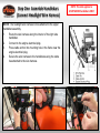
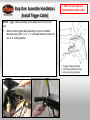
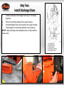
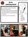
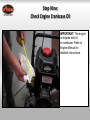
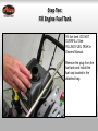
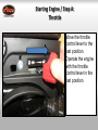
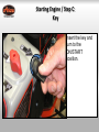
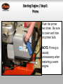
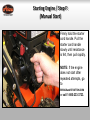
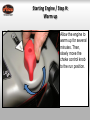
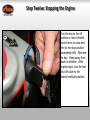
1
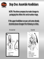
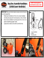
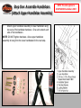
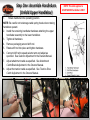
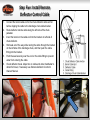
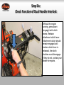
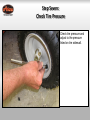
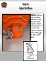
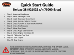
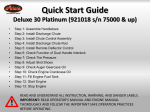
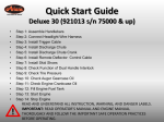
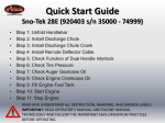
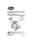
Quick Start Guide
Deluxe 24 Platinum (921017 s/n 75000 & up)
•
•
•
•
•
•
•
•
•
•
•
•
•
Step 1: Assemble Handlebars
Step 2: Install Discharge Chute
Step 3: Install Chute Control Assembly
Step 4: Install Discharge Chute Rod
Step 5: Install Remote Deflector Control
Step 6: Check Function of Dual Handle Interlock
Step 7: Check Tire Pressure
Step 8: Adjust Skid Shoes
Step 9: Check Auger Gearcase Oil
Step 10: Check Engine Crankcase Oil
Step 11: Fill Engine Fuel Tank
Step 12: Start Engine
Step 13: Stop Engine
READ AND UNDERSTAND ALL INSTRUCTION, WARNING, AND DANGER LABELS.
IMPORTANT: READ OPERATOR’S MANUAL AND ENGINE MANUAL
THOROUGHLY AND FOLLOW THE IMPORTANT SAFE OPERATION PRACTICES
BEFORE OPERATING.
Step One: Assemble Handlebars
NOTE: The Ariens company has made changes to
packaging that affects this serial number range.
If the upper handlebars on your unit came already
attached please disregard the following six slides.
Not attached
Attached
Step One: Assemble Handlebars
(Unfold Lower Handlebar)
IMPORTANT: Be sure to block wheels or secure unit so it does not
move during assembly.
1.
Rotate lower handlebar out from unit so lower handlebar
mounting holes align with mounting holes on the unit frame.
2.
Secure lower handlebar to unit using two 3/8 in x 3/4 in. hex
head serrated flange grade 5 bolts.
3.
Tighten all four bolts to 25-42 lbf-ft (33,9-56,9 N∙m)
NOTE: This slide applies to
UNATTACHED handlebars ONLY
Step One: Assemble Handlebars
(Attach Upper Handlebar Assembly)
1.
Attach upper handlebar assembly to lower handlebar using
two sets of the handlebar hardware. One set to attach each
side of the handlebars.
NOTE: DO NOT tighten hardware. Allow upper handlebar
assembly to hang from the lower handlebars for the next step.
NOTE: This slide applies to
UNATTACHED handlebars ONLY
Step One: Assemble Handlebars
(Attach Control Cables)
1.
Hook Spring end of attachment control cable to the clutch
arm.
2.
Hook spring end of the traction control cable to the cable
eyelet on back of frame.
NOTE: Make sure the cable remains in the groove of the pulley.
NOTE: This slide applies to
UNATTACHED handlebars ONLY
Step One: Assemble Handlebars
(Unfold Upper Handlebar)
Rotate handlebar into operating
position.
Assembly)
1.
NOTE: Be careful not to damage cable spring hooks when rotating
handlebar upward.
2. Install the remaining handlebar hardware attaching the upper
handlebar assembly to the lower handlebar.
3. Tighten all hardware.
4. Remove packaging around shift rod.
5. Rotate shift rod into place and tighten hardware.
6. Connect shift rod to speed selector arm and adjust as
specified. See Selector Adjustment in the Owners Manual.
7. Adjust attachment cable as specified. See Attachment
Clutch/Brake Adjustment in the Owners Manual.
8. Adjust the traction cable as specified. See Traction Drive
Clutch Adjustment in the Owners Manual.
NOTE: This slide applies to
UNATTACHED handlebars ONLY
Step One: Assemble Handlebars
(Connect Headlight Wire Harness)
NOTE: The headlight wire harness comes attached to the upper
handlebar assembly.
1.
Route the wire harness along the interior of the right side
handlebar.
2.
Connect to the engine electrical plug.
3.
Press cable anchor into mounting hole in the frame near the
engine electrical plug.
4.
Secure the wire harness to the handlebars using the cable
ties attached to the wire harness.
NOTE: This slide applies to
UNATTACHED handlebars ONLY
Step One: Assemble Handlebars
(Install Trigger Cable)
NOTE: Trigger cable assembly comes attached to the Sno-thro
unit.
1. Attach remote trigger cable assembly to upper handlebar
assembly using one ¼ in x 1- ½ oval head machine screw and
one ¼ in. locking washer.
NOTE: This slide applies to
UNATTACHED handlebars ONLY
Step One:
Assemble Handlebar
1.
Remove the lower and loosen the upper hardware on the
handlebar assembly.
2.
Loosen the hardware on the shift rod.
3.
Put the speed selector lever in the sixth forward position.
4.
Rotate the handlebar into operating position.
NOTE: Be careful not to damage cable spring hooks when rotating
handlebar upward.
5.
Install and tighten the hardware on the handlebar assembly
and shift rod.
NOTE: This slide applies to
ATTACHED handlebars ONLY
Step Two:
Install Discharge Chute
1.
Grease underside of discharge chute ring (if not already
greased).
2.
Remove mounting hardware from auger housing.
3.
Install discharge chute over opening in the auger housing.
Finger tighten the mounting hardware removed above.
NOTE: Leave discharge chute pedestal loose to help install the
chute crank.
Step Three: Install Chute Control
Assembly
1.
2.
Remove the gear cover from top of chute pedestal.
Release the lock teeth on the gear assembly with your finger
and rotate the discharge chute so it points straight ahead.
NOTE: Make sure alignment markers are lined up when discharge
chute is pointing straight ahead.
Step Three: Install Chute Control
Assembly Cont.
3.
4.
5.
Remove the rubber grommet from the control panel.
Make sure the chute control cable is routed between the lower
handlebar and the bottom of the control panel, insert control
assembly into slot in control panel from below and install
assembly into nylon bushing in control panel.
Reinstall rubber grommet over control assembly knob and into
control panel.
Step Four:
Install Discharge Chute Rod
NOTE: To ensure the discharge chute follows its full range of travel,
make sure the control lever is centered in the slot and pointing
straight up before installing the chute rod.
1. Insert chute rod end without ears into control lever and slide into
control panel until opposite end of rod clears the gear assembly.
2. Align end of chute rod with hex hole in gear assembly and insert
until ears hit gear.
3. Insert hairpin into hole in chute rod near gear assembly.
Step Four:
Install Discharge Chute Rod Cont.
4. Hook the chute control cable onto the chute rod.
IMPORTANT: The chute control cable hook will prevent the cable
from contacting the engine or muffler guard. Make sure the cable
stays connected while unit is in operation.
5. Check to make sure the chute control cable ends are properly
seated in control assembly and control arm.
6. Replace gear cover on top of chute pedestal.
7. Orient the chute and pedestal to its most vertical position and
tighten pedestal hardware to 15-31 lbf-ft (20-42 N∙m).
8. Make sure the discharge chute rotates left and right when you
push the discharge chute control lever left and right.
NOTE: If chute does not stay in position, adjust as directed in
Discharge Chute Control in Owner Manual.
Step Five: Install Remote
Deflector Control Cable
1.
2.
3.
4.
5.
6.
Connect the barrel cable end to the chute deflector cable anchor
before clipping the cable to the discharge chute cable bracket.
Route deflector remote cable along the left side of the chute
pedestal.
Insert the barrel on the cable end into the bracket on left side of
chute deflector.
Hold seal out of the way while routing the cable through the bracket
on the left side of the discharge chute, and then push the cable
fitting into the bracket.
Push the seal securely over the end on the cable fitting to prevent
water from entering the cable.
Check deflector travel. Adjust nut on cable end under handlebar to
obtain full travel, if necessary see Remote Deflector Control in
Owners Manual.
Step Six:
Check Function of Dual Handle Interlock
Without the engine
running, press down
(engage) both clutch
levers. Release
attachment clutch lever.
Attachment clutch should
remain engaged until
traction clutch lever is
released, then both
clutches must disengage.
If they do not, contact your
dealer for repairs.
Step Seven:
Check Tire Pressure
Check tire pressure and
adjust to the pressure
listed on tire sidewall.
Step Six:
Adjust Skid Shoes
IMPORTANT: Skid shoes
should be adjusted as
conditions require. Allow
1/8 in. (3mm) between
scraper blade and hard
smooth surfaces. Allow 7/8
in (22 mm) between
scraper blade and uneven
or gravel surfaces. (See
Skid Shoes in Owners
Manual).
Step Eight:
Check Auger Gearcase Oil
Check oil level in auger
gearcase
(see Check Auger
Gearcase in Owners
Manual).
Step Nine:
Check Engine Crankcase Oil
IMPORTANT: The engine
is shipped with oil
in crankcase. Refer to
Engine Manual for
detailed instructions.
Step Ten:
Fill Engine Fuel Tank
Fill fuel tank. DO NOT
OVERFILL! See
FILLING FUEL TANK in
Owners Manual.
Remove the plug from the
fuel tank and install the
fuel cap located in the
attached bag.
Step Eleven: Starting the Engine
Starting Engine / Step A:
Throttle
Move the throttle
control lever to the
fast position.
Operate the engine
with the throttle
control lever in the
fast position.
Starting Engine / Step B:
Fuel Valve
Turn the fuel shutoff valve to the ON
position.
Starting Engine / Step C:
Key
Insert the key and
turn to the
ON/START
position.
Starting Engine / Step D:
Choke
Turn the choke
control knob to the
choke position.
NOTE: Choke is
usually
unnecessary
when restarting a
warm engine.
Starting Engine / Step E:
Prime
Push the primer
two times. Be sure
to cover vent hole
on primer bulb.
NOTE: Priming is
usually
unnecessary when
restarting a warm
engine.
Starting Engine / Step F:
(Manual Start)
Firmly hold the starter
cord handle. Pull the
starter cord handle
slowly until resistance
is felt, then pull rapidly.
NOTE: If the engine
does not start after
repeated attempts, go
to
BRIGGSandSTRATTON.COM
or call 1-800-233-3723.
Starting Engine / Step F:
(Electric Start)
First connect the
extension cord to the
power cord receptacle
and then into a wall
receptacle. If an
additional extension
cord is required, make
sure it is a 3-wire
grounded extension
cord.
Starting Engine / Step G:
(Electric Start)
Depress the push
button. After you
start the engine,
first disconnect the
extension cord from
the wall receptacle
and then from the
power cord
receptacle.
Starting Engine / Step H:
Warm up
Allow the engine to
warm up for several
minutes. Then,
slowly move the
choke control knob
to the run position.
Step Twelve: Stopping the Engine
Turn the key to the off
position or move throttle
control lever to slow and
then to the stop position
(completely left). Remove
the key. Keep away from
reach of children. After
engine stops, turn the fuel
shut-off valve to the
closed (vertical) position.
Additional Resources
• Refer to Owners Manual and Engine Manual
• Contact Ariens Company
www.ariens.com
Phone: 920-756-4688
E-mail: [email protected]
• For issues concerning engine, please contact Briggs
and Stratton
www.BRIGGSandSTRATTON.com
Phone: 800-233-3723
2012 The Ariens Company. All rights reserved.