1
Netopia® Software User Guide
Firmware Version 7.4.2
for eircom broadband
Netopia® 3300 Series Gateways
February 2005
Copyright
Copyright © 2005 Netopia, Inc.
V 7.4.2-EIR
All rights reserved.
Netopia, Inc. Netopia and the Netopia logo are registered trademarks belonging to Netopia, Inc., registered U.S. Patent
and Trademark Office. Broadband Without Boundaries and 3-D Reach are trademarks belonging to Netopia, Inc. All other
trademarks are the property of their respective owners. All rights reserved.
Netopia, Inc. Part Number: 6161201-00-01
2
Table of Contents
Table of Contents
Copyright
Introduction
..........................................2
.................................. 7
Intended Audience
...................................7
About Netopia Documentation . . . . . . . . . . . . . . . . . . . . . . . . . .
Organization . . . . . . . . . . . . . . . . . . . . . . . . . . . . . . . . . . . . . . . .
A Word About Example Screens . . . . . . . . . . . . . . . . . . . . . . . .
Documentation Conventions . . . . . . . . . . . . . . . . . . . . . . . . . . .
CHAPTER 1
Overview of Major Capabilities . . . . . . . . . . . . . . . . . . 11
Wide Area Network Termination . . . . . . . . . . . . . . . . . . . . . . . .
Simplified Local Area Network Setup . . . . . . . . . . . . . . . . . . . .
Management
......................................
Security
..........................................
CHAPTER 2
7
8
8
9
12
14
15
17
Basic Mode Setup . . . . . . . . . . . . . . . . . . . . . . . . . . . . 23
Important Safety Instructions
Set up the Netopia Gateway
. . . . . . . . . . . . . . . . . . . . . . . . . . 24
. . . . . . . . . . . . . . . . . . . . . . . . . . 25
Configure the Netopia Gateway . . . . . . . . . . . . . . . . . . . . . . . .
Netopia Gateway Status Indicator Lights . . . . . . . . . . . . . . . . .
Accessing the Web User Interface . . . . . . . . . . . . . . . . . . . . . .
Links Bar
.........................................
Home . . . . . . . . . . . . . . . . . . . . . . . . . . . . . . . . . . . . . . . . . . . .
28
30
32
33
34
Firewall . . . . . . . . . . . . . . . . . . . . . . . . . . . . . . . . . . . . . . . . . . . . . . . .
Wireless. . . . . . . . . . . . . . . . . . . . . . . . . . . . . . . . . . . . . . . . . . . . . . . .
Gaming . . . . . . . . . . . . . . . . . . . . . . . . . . . . . . . . . . . . . . . . . . . . . . . .
Expert Mode . . . . . . . . . . . . . . . . . . . . . . . . . . . . . . . . . . . . . . . . . . . .
Troubleshoot . . . . . . . . . . . . . . . . . . . . . . . . . . . . . . . . . . . . . . . . . . . .
Access Control Login. . . . . . . . . . . . . . . . . . . . . . . . . . . . . . . . . . . . . .
35
39
51
57
58
63
3
Table of Contents
Help . . . . . . . . . . . . . . . . . . . . . . . . . . . . . . . . . . . . . . . . . . . . . . . . . . . 64
CHAPTER 3
Expert Mode . . . . . . . . . . . . . . . . . . . . . . . . . . . . . . . . . 65
Access the Expert Web Interface . . . . . . . . . . . . . . . . . . . . . . . 65
Links Bar . . . . . . . . . . . . . . . . . . . . . . . . . . . . . . . . . . . . . . . . . . 69
Configure . . . . . . . . . . . . . . . . . . . . . . . . . . . . . . . . . . . . . . . . . . . . . . . 70
Connection . . . . . . . . . . . . . . . . . . . . . . . . . . . . . . . . . . . . . . . . . . . . . . 71
Wireless . . . . . . . . . . . . . . . . . . . . . . . . . . . . . . . . . . . . . . . . . . . . . . . . 73
Access Control . . . . . . . . . . . . . . . . . . . . . . . . . . . . . . . . . . . . . . . . . . . 85
DHCP Server . . . . . . . . . . . . . . . . . . . . . . . . . . . . . . . . . . . . . . . . . . . . 96
IP Passthrough . . . . . . . . . . . . . . . . . . . . . . . . . . . . . . . . . . . . . . . . . . . 98
NAT. . . . . . . . . . . . . . . . . . . . . . . . . . . . . . . . . . . . . . . . . . . . . . . . . . . 100
Packet Filter . . . . . . . . . . . . . . . . . . . . . . . . . . . . . . . . . . . . . . . . . . . . 106
QoS. . . . . . . . . . . . . . . . . . . . . . . . . . . . . . . . . . . . . . . . . . . . . . . . . . . 135
Router Password . . . . . . . . . . . . . . . . . . . . . . . . . . . . . . . . . . . . . . . . 138
Time Zone. . . . . . . . . . . . . . . . . . . . . . . . . . . . . . . . . . . . . . . . . . . . . . 139
VLAN . . . . . . . . . . . . . . . . . . . . . . . . . . . . . . . . . . . . . . . . . . . . . . . . . 140
Statistics . . . . . . . . . . . . . . . . . . . . . . . . . . . . . . . . . . . . . . . . . . . . . . . 145
Diagnostics . . . . . . . . . . . . . . . . . . . . . . . . . . . . . . . . . . . . . . . . . . . . . 152
Remote Access. . . . . . . . . . . . . . . . . . . . . . . . . . . . . . . . . . . . . . . . . . 154
Update Router . . . . . . . . . . . . . . . . . . . . . . . . . . . . . . . . . . . . . . . . . . 155
Reset Router. . . . . . . . . . . . . . . . . . . . . . . . . . . . . . . . . . . . . . . . . . . . 157
Restart Router . . . . . . . . . . . . . . . . . . . . . . . . . . . . . . . . . . . . . . . . . . 158
Basic Mode . . . . . . . . . . . . . . . . . . . . . . . . . . . . . . . . . . . . . . . 159
Help
. . . . . . . . . . . . . . . . . . . . . . . . . . . . . . . . . . . . . . . . . . . . 160
CHAPTER 4
Basic Troubleshooting . . . . . . . . . . . . . . . . . . . . . . . . 161
Status Indicator Lights . . . . . . . . . . . . . . . . . . . . . . . . . . . . . . 162
Factory Reset Switch . . . . . . . . . . . . . . . . . . . . . . . . . . . . . . . 169
CHAPTER 5
Command Line Interface . . . . . . . . . . . . . . . . . . . . . . 171
Overview . . . . . . . . . . . . . . . . . . . . . . . . . . . . . . . . . . . . . . . . . 172
Starting and Ending a CLI Session . . . . . . . . . . . . . . . . . . . . . 174
Using the CLI Help Facility . . . . . . . . . . . . . . . . . . . . . . . . . . . 175
About SHELL Commands . . . . . . . . . . . . . . . . . . . . . . . . . . . . 175
4
Table of Contents
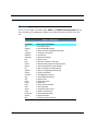
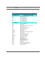
SHELL Commands . . . . . . . . . . . . . . . . . . . . . . . . . . . . . . . . . 176
About CONFIG Commands . . . . . . . . . . . . . . . . . . . . . . . . . . 187
CONFIG Commands . . . . . . . . . . . . . . . . . . . . . . . . . . . . . . . 191
CHAPTER 6
Glossary . . . . . . . . . . . . . . . . . . . . . . . . . . . . . . . . 247
CHAPTER 7
Technical Specifications and Safety Information . . . . 265
Description . . . . . . . . . . . . . . . . . . . . . . . . . . . . . . . . . . . . . . .
Agency approvals . . . . . . . . . . . . . . . . . . . . . . . . . . . . . . . . . .
Manufacturer’s Declaration of Conformance . . . . . . . . . . . . .
Important Safety Instructions . . . . . . . . . . . . . . . . . . . . . . . . .
47 CFR Part 68 Information . . . . . . . . . . . . . . . . . . . . . . . . . .
Electrical Safety Advisory . . . . . . . . . . . . . . . . . . . . . . . . . . . .
265
267
268
270
271
272
Index . . . . . . . . . . . . . . . . . . . . . . . . . . . . . . . . . . . . . . . . . . . . . 273
5
Table of Contents
6
Intended Audience
Introduction
Intended Audience
This guide is targeted primarily to residential service subscribers.
Advanced sections may also be of use to the support staffs of broadband service providers and advanced residential service subscribers. See “Expert Mode” on page 65.
About Netopia Documentation
Netopia, Inc. provides a suite of technical information for its 3300-series family of intelligent enterprise and consumer Gateways. It consists of:
• Software User Guide
• Dedicated Quickstart guides
• Specific White Papers
The documents are available in electronic form as Portable Document Format (PDF) files.
They are viewed (and printed) from Adobe Acrobat Reader, Exchange, or any other application that supports PDF files.
They are downloadable from Netopia’s website: http://www.netopia.com/
☛
NOTE:
This guide describes the wide variety of features and functionality of the Netopia Gateway, when used in Router mode. The Netopia Gateway may also be
delivered in Bridge mode. In Bridge mode, the Gateway acts as a pass-through
device and allows the workstations on your LAN to have public addresses
directly on the Internet.
Introduction
7
Introduction
Organization
This guide consists of six chapters, including a glossary, and an index. It is organized as
follows:
• “Introduction” — Describes the Netopia document suite, the purpose of, the audience
for, and structure of this guide. It gives a table of conventions.
• Chapter 1, “Overview of Major Capabilities” — Presents a product description sum•
•
•
•
•
•
•
mary.
Chapter 2, “Basic Mode Setup” — Describes how to get up and running with your
Netopia Gateway, and the Basic Mode Web-based user interface.
Chapter 3, “Expert Mode” — Focuses on the Expert Mode Web-based user interface
for advanced users. It is organized in the same way as the Web UI is organized. As you
go through each section, functions and procedures are discussed in detail.
Chapter 4, “Basic Troubleshooting” — Gives some simple suggestions for troubleshooting problems with your Gateway’s initial configuration.
Chapter 5, “Command Line Interface” — Describes all the current text-based commands for both the SHELL and CONFIG modes. A summary table and individual command examples for each mode is provided.
Chapter 6, “Glossary”
Chapter 7, “Technical Specifications and Safety Information”
Index
A Word About Example Screens
This manual contains many example screen illustrations. Since Netopia 3300 Series Gateways offer a wide variety of features and functionality, the example screens shown may not
appear exactly the same for your particular Gateway or setup as they appear in this manual. The example screens are for illustrative and explanatory purposes, and should not be
construed to represent your own unique environment.
8
Introduction
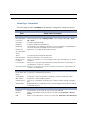
Documentation Conventions
Documentation Conventions
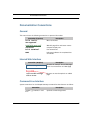
General
This manual uses the following conventions to present information:
Convention (Typeface)
Description
bold italic
monospaced
Menu commands
bold italic sans serif
Web GUI page links and button names
Computer display text
terminal
bold terminal
Italic
User-entered text
Italic type indicates the complete titles
of manuals.
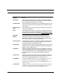
Internal Web Interface
Convention (Graphics)
Description
light blue rectangle or line
Denotes an “excerpt” from a Web page
or the visual truncation of a Web page
solid rounded rectangle
with an arrow
Denotes an area of emphasis on a Web
page
Command Line Interface
Syntax conventions for the Netopia Gateway command line interface are as follows:
Convention
straight ([ ]) brackets in cmd
line
Introduction
Description
Optional command arguments
9
Introduction
curly ({ }) brackets, with values Alternative values for an argument are
separated with vertical bars (|). presented in curly ({ }) brackets, with
values separated with vertical bars (|).
bold terminal type User-entered text
face
italic terminal
type face
10
Introduction
Variables for which you supply your own
values
CHAPTER 1
Overview of Major
Capabilities
The Netopia Gateway offers simplified setup and management features as well as
advanced broadband Gateway capabilities. The following are some of the main features of
the Netopia Gateway:
• “Wide Area Network Termination” on page 12
The Gateway combines an ADSL modem with an Internet Gateway. It translates protocols used on the Internet to protocols used by home personal computers and eliminates the need for special desktop software (i.e. PPPoE).
• “Simplified Local Area Network Setup” on page 14
Built-in DHCP and DNS proxy features minimize or eliminate the need to program any
network configuration into your home personal computer. UPnP™ feature allows ease of
connection with many compatible networked devices.
• “Management” on page 15
A Web server built into the Netopia Operating System makes setup and maintenance
easy using standard browsers. Diagnostic tools facilitate troubleshooting.
• “Security” on page 17
Network Address Translation (NAT), password protection, Stateful Inspection firewall
and other built-in security features prevent unauthorized remote access to your network.
NAT Games and other services, default server, and other features permit access to
computers on your home network that you can specify. VPN technology (standard VPN
Passthrough and optional IPSec tunnelling) enables telecommuters, mobile workforce
11
and branch offices to safely and affordably connect to a remote business network, for
effective communication and collaboration.
Wide Area Network Termination
PPPoE/PPPoA (Point-to-Point Protocol over Ethernet/ATM)
The PPPoE specification, incorporating the PPP and Ethernet standards, allows your computer(s) to connect to your Service Provider’s network through your Ethernet WAN connection. The 3300-series Gateway supports PPPoE, eliminating the need to install PPPoE
client software on any LAN computers.
Service Providers may require the use of PPP authentication protocols such as Challenge
Handshake Authentication Protocol (CHAP) or Password Authentication Protocol (PAP).
CHAP and PAP use a username and password pair to authenticate users with a PPP server.
A CHAP authentication process works as follows:
1.
2.
3.
The password is used to scramble a challenge string.
The password is a shared secret, known by both peers.
The unit sends the scrambled challenge back to the peer.
PAP, a less robust method of authentication, sends a username and password to a PPP
server to be authenticated. PAP’s username and password pair are not encrypted, and are
therefore sent “unscrambled”.
Instant-On PPP
You can configure your Gateway for one of two types of Internet connections:
• Always On
• Instant On
These selections provide either an uninterrupted Internet connection or an as-needed connection.
12
Wide Area Network Termination
While an Always On connection is convenient, it does leave your network permanently connected to the Internet, and therefore potentially vulnerable to attacks.
Netopia's Instant On technology furnishes almost all the benefits of an Always-On connection while providing two additional security benefits:
• Your network cannot be attacked when it is not connected.
• Your network may change address with each connection making it more difficult to
attack.
When you configure Instant On access, you can also configure an idle time-out value. Your
Gateway monitors traffic over the Internet link and when there has been no traffic for the
configured number of seconds, it disconnects the link.
When new traffic that is destined for the Internet arrives at the Gateway, the Gateway will
instantly re-establish the link.
Your service provider may be using a system that assigns the Internet address of your
Gateway out of a pool of many possible Internet addresses. The address assigned varies
with each connection attempt, which makes your network a moving target for any attacker.
13
Simplified Local Area Network Setup
DHCP (Dynamic Host Configuration Protocol) Server
DHCP Server functionality enables the Gateway to assign to your LAN computer(s) a “private” IP address and other parameters that allow network communication. The default
DHCP Server configuration of the Gateway supports up to 253 LAN IP addresses.
This feature simplifies network administration because the Gateway maintains a list of IP
address assignments. Additional computers can be added to your LAN without the hassle
of configuring an IP address.
DNS Proxy
Domain Name System (DNS) provides end users with the ability to look for devices or web
sites by typing their names, rather than IP addresses. For web surfers, this technology
allows you to enter the URL (Universal Resource Locator) as text to surf to a desired website.
The Netopia DNS Proxy feature allows the LAN-side IP address of the Gateway to be used
for proxying DNS requests from hosts on the LAN to the DNS Servers configured in the
gateway. This is accomplished by having the Gateway's LAN address handed out as the
“DNS Server” to the DHCP clients on the LAN.
☛
NOTE:
The Netopia DNS Proxy only proxies UDP DNS queries, not TCP DNS queries.
UPnP™
Universal Plug and Play (UPnP™) is a set of protocols that allows a PC to automatically discover other UPnP devices (anything from an internet gateway device to a light switch),
retrieve an XML description of the device and its services, control the device, and subscribe to real-time event notification. PCs using UPnP can retrieve the Gateway’s WAN IP
address, and automatically create NAT port maps. This means that applications that support UPnP, and are used with a UPnP-enabled Netopia Gateway, will not need application
layer gateway support on the Netopia Gateway to work through NAT. By default, UPnP is
enabled on the Netopia Gateway.
14
Management
Management
Embedded Web Server
There is no specialized software to install on your PC to configure, manage, or maintain
your Netopia Gateway. Web pages embedded in the operating system provide access to
the following Gateway operations:
• Setup
• System and security logs
• Diagnostics functions
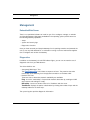
Once you have removed your Netopia Gateway from its packing container and powered the
unit up, use any LAN attached PC or workstation running a common web browser application to configure and monitor the Gateway.
Diagnostics
In addition to the Gateway’s visual LED indicator lights, you can run an extensive set of
diagnostic tools from your Web browser.
Two of the facilities are:
• Automated “Multi-Layer” Test
The Run Diagnostics link initiates a sequence of tests. They examine the entire
functionality of the Gateway, from the physical connections to the data traffic.
• Network Test Tools
Three test tools to determine network reachability are available:
Ping - tests the “reachability” of a particular network destination by sending an ICMP
echo request and waiting for a reply.
NSLookup - converts a domain name to its IP address and vice versa.
TraceRoute - displays the path to a destination by showing the number of hops and the
Gateway addresses of these hops.
The system log also provides diagnostic information.
15
☛
NOTE:
Your Service Provider may request information that you acquire from these various diagnostic tools. Individual tests may be performed at the command line.
(See “Command Line Interface” on page 171.).
16
Security
Security
Remote Access Control
You can determine whether or not an administrator or other authorized person has access
to configuring your Gateway. This access (either time-restricted or unlimited until the router
is rebooted) can be turned on or off in the Web interface. Additionally, permanent remote
access can be configured in the CLI.
Password Protection
Access to your Netopia device can be controlled through two access control accounts,
Admin or User.
• The Admin, or administrative user, performs all configuration, management or maintenance operations on the Gateway.
• The User account provides monitor capability only.
A user may NOT change the configuration, perform upgrades or invoke maintenance
functions.
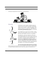
Network Address Translation (NAT)
The Netopia Gateway Network Address Translation (NAT) security feature lets you conceal
the topology of a hard-wired Ethernet or wireless network connected to its LAN interface
from Gateways on networks connected to its WAN interface. In other words, the end computer stations on your LAN are invisible from the Internet.
Only a single WAN IP address is required to provide this security support for your entire
LAN.
LAN sites that communicate through an Internet Service Provider typically enable NAT,
since they usually purchase only one IP address from the ISP.
• When NAT is ON, the Netopia Gateway “proxies” for the end computer stations on your
network by pretending to be the originating host for network communications from nonoriginating networks. The WAN interface address is the only IP address exposed.
The Netopia Gateway tracks which local hosts are communicating with which remote
hosts. It routes packets received from remote networks to the correct computer on the
LAN (Ethernet) interface.
17
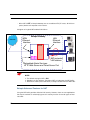
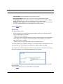
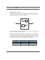
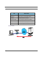
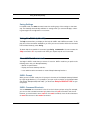
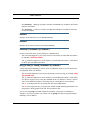
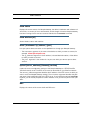
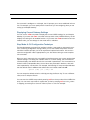
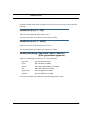
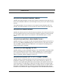
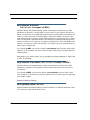
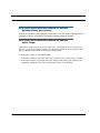
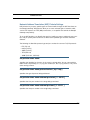
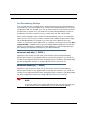
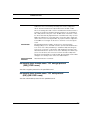
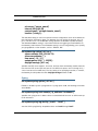
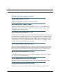
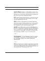
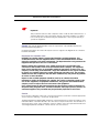
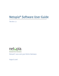
• When NAT is OFF, a Netopia Gateway acts as a traditional TCP/IP router, all LAN computers/devices are exposed to the Internet.
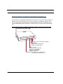
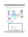
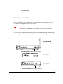
A diagram of a typical NAT-enabled LAN follows:
Netopia Gateway
WAN
Ethernet
Interface
Internet
LAN
Ethernet
Interface
NAT
NAT-protected
LAN stations
Embedded Admin Services:
HTTP-Web Server and Telnet Server Port
☛
NOTE:
1. The default setting for NAT is ON.
2. Netopia uses Port Address Translation (PAT) to implement the NAT facility.
3. NAT Pinhole traffic (discussed below) is always initiated from the WAN side.
Netopia Advanced Features for NAT
Using the NAT facility provides effective LAN security. However, there are user applications
that require methods to selectively by-pass this security function for certain types of Internet traffic.
18
Security
Netopia Gateways provide special gaming and other service configuration tools that enable
you to establish NAT-protected LAN layouts that still provide flexible by-pass capabilities.
Some of these rules require coordination with the unit’s embedded administration services: the internal Web (HTTP) Port (TCP 80) and the internal Telnet Server Port (TCP 23).
Internal Servers
The internal servers are the embedded Web and Telnet servers of the Gateway. You would
change the internal server ports for Web and Telnet of the Gateway if you wanted to have
these services on the LAN using pinholes or the Default server. Pinhole configuration rules
provide an internal port forwarding facility that enables you to eliminate conflicts with
embedded administrative ports 80 and 23.
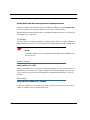
Default Server
This feature allows you to:
• Direct your Gateway to forward all externally initiated IP traffic (TCP and UDP protocols
only) to a default host on the LAN.
• Enable it for certain situations:
Where you cannot anticipate what port number or packet protocol an in-bound application might use.
For example, some network games select arbitrary port numbers when a connection is
opened.
When you want all unsolicited traffic to go to a specific LAN host.
Combination NAT Bypass Configuration
Specific Games and services and Default Server settings, each directed to different LAN
devices, can be used together.
☛
WARNING:
NAT Bypass configuration allows inbound access to the specified LAN station.
Contact your Network Administrator for LAN security questions.
19
IP-Passthrough
The Netopia Gateway now offers an IP passthrough feature. The IP passthrough feature
allows a single PC on the LAN to have the Gateway’s public address assigned to it. It also
provides PAT (NAPT) via the same public IP address for all other hosts on the private LAN
subnet.
VPN IPSec Pass Through
This Netopia service supports your independent VPN client software in a transparent manner. Netopia has implemented an Application Layer Gateway (ALG) to support multiple PCs
running IP Security protocols.
This feature has three elements:
1.
2.
3.
20
On power up or reset, the address mapping function (NAT) of the Gateway’s WAN configuration is turned on by default.
When you use your third-party VPN application, the Gateway recognizes the traffic
from your client and your unit. It allows the packets to pass through the NAT “protection layer” via the encrypted IPSec tunnel.
The encrypted IPSec tunnel is established “through” the Gateway.
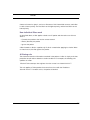
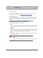
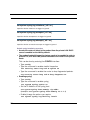
Security
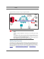
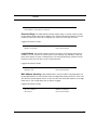
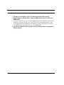
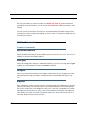
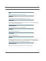
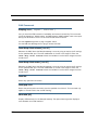
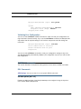
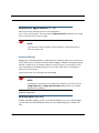
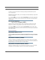
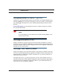
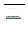
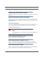
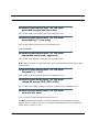
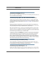
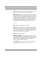
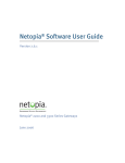
A typical VPN IPSec Tunnel pass through is diagrammed below:
Netopia
Gateway
☛
NOTE:
Typically, no special configuration is necessary to use the IPSec pass through
feature.
In the diagram, VPN PC clients are shown behind the Netopia Gateway and the
secure server is at Corporate Headquarters across the WAN. You cannot have
your secure server behind the Netopia Gateway.
When multiple PCs are starting IPSec sessions, they must be started one at a
time to allow the associations to be created and mapped.
VPN IPSec Tunnel Termination
This Netopia service supports termination of VPN IPsec tunnels at the Gateway. This permits tunnelling from the Gateway without the use of third-party VPN client software on your
client PCs. Currently one IPSec VPN tunnel is supported on Netopia 3300 Series Gateways. Unlike VPN Passthrough, IPsec VPN tunnel is a keyed feature that you can obtained
from Netopia. See “Software Feature Keys” on page 178 and “IPSec Settings” on
page 226.
21
Dynamic DNS
Dynamic DNS support allows you to use the free services of www.dyndns.org. Dynamic
DNS automatically directs any public Internet request for your computer's name to your current dynamically-assigned IP address. This allows you to get to the IP address assigned to
your Gateway, even though your actual IP address may change as a result of a PPPoE connection to the Internet. See “Dynamic DNS Settings” on page 197.
Stateful Inspection Firewall
Stateful inspection is a security feature that prevents unsolicited inbound access when
NAT is disabled. You can configure UDP and TCP “no-activity” periods that will also apply to
NAT time-outs if stateful inspection is enabled on the interface. Technical details are discussed in “Stateful Inspection” on page 220.
22
CHAPTER 2
Basic Mode Setup
Most users will find that the basic Quickstart configuration is all that they ever need to use.
This section may be all that you ever need to configure and use your Netopia Gateway. The
following instructions cover installation in Router Mode.
This section covers:
•
•
•
•
•
•
“Important Safety Instructions” on page 24
“Set up the Netopia Gateway” on page 25
“Configure the Netopia Gateway” on page 28
“Netopia Gateway Status Indicator Lights” on page 30
“Accessing the Web User Interface” on page 32
“Links Bar” on page 33
23
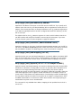
Important Safety Instructions
POWER SUPPLY INSTALLATION
Connect the power supply cord to the power jack on the Netopia Gateway. Plug the power
supply into an appropriate electrical outlet.
☛
CAUTION:
Depending on the power supply provided with the product, either the direct
plug-in power supply blades, power supply cord plug or the appliance coupler
serves as the mains power disconnect. It is important that the direct plug-in
power supply, socket-outlet or appliance coupler be located so it is readily
accessible.
CAUTION (North America Only): For use only with a CSA Certified or UL
Listed Limited Power Source or Class 2 power supply, rated 12Vdc, 1.5A.
(Sweden) Apparaten skall anslutas till jordat uttag när den ansluts till ett
nätverk
(Norway) Apparatet må kun tilkoples jordet stikkontakt.
USB-powered models: For Use with Listed I.T.E. Only
TELECOMMUNICATION INSTALLATION
When using your telephone equipment, basic safety precautions should always be followed
to reduce the risk of fire, electric shock and injury to persons, including the following:
• Do not use this product near water, for example, near a bathtub, wash bowl, kitchen
sink or laundry tub, in a wet basement or near a swimming pool.
• Avoid using a telephone (other than a cordless type) during an electrical storm. There
may be a remote risk of electrical shock from lightning.
• Do not use the telephone to report a gas leak in the vicinity of the leak.
SAVE THESE INSTRUCTIONS
24
Set up the Netopia Gateway
Set up the Netopia Gateway
Refer to your Quickstart Guide for instructions on how to connect your Netopia Gateway to
your power source, PC or local area network, and your Internet access point, whether it is a
dedicated DSL outlet or a DSL or cable modem. Different Netopia Gateway models are
supplied for any of these connections. Be sure to enable Dynamic Addressing on your PC.
Perform the following:
25
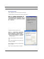
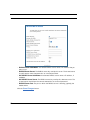
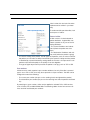
Microsoft Windows:
Step 1. Navigate to the TCP/IP Properties Control Panel.
a. Windows 98, ME. and 2000 versions follow a path like this:
Start menu -> Settings -> Control Panel -> Network (or Network and Dial-up Connections ->
Local Area Connection -> Properties) -> TCP/IP
[your_network_card] or Internet Protocol [TCP/
IP] -> Properties
b. Windows XP follows a path like this:
Start menu -> Control Panel -> Network and
Internet Connections -> Network Connections -> Local Area Connection -> Properties
-> Internet Protocol [TCP/IP] -> Properties
Then go to Step 2.
Step 2. Select Obtain an IP address automatically.
Step 3. Select Obtain DNS server address automatically, if available.
Step 4. Remove any previously configured Gateways, if available.
Step 5. OK the settings. Restart if prompted.
26
Set up the Netopia Gateway
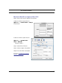
Macintosh MacOS 9 or higher or Mac OS X:
Step 1. Access the TCP/IP or Network control panel.
a. Mac OS 9 follows a path like this:
Apple Menu -> Control Panels -> TCP/IP
Control Panel
b. Mac OS X follows a path like this:
Apple Menu -> System Preferences -> Network
Then go to Step 2.
Step 2. Select Built-in Ethernet
Step 3. Select Configure Using DHCP
Step 4. Close and Save, if prompted.
Proceed to “Configure the Netopia
Gateway” on page 28.
27
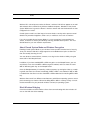
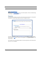
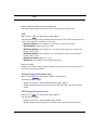
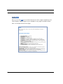
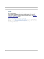
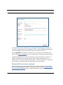
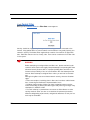
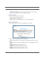
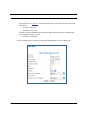
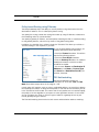
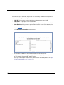
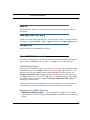
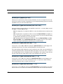
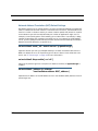
Configure the Netopia Gateway
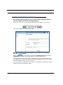
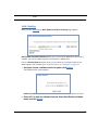
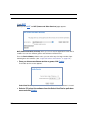
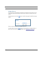
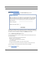
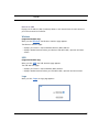
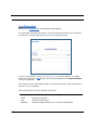
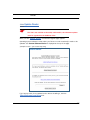
1.
Run your Web browser application, such as Firefox or Microsoft Internet Explorer,
from the computer connected to the Netopia Gateway.
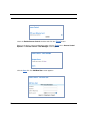
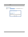
Enter http://192.168.1.254 in the URL Address text box. Press Enter or click Go.
The browser displays the Internet Login page.
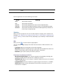
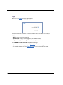
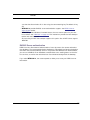
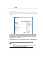
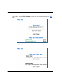
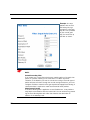
2.
28
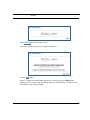
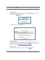
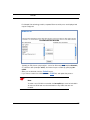
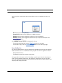
Enter the User Name and Password supplied by your Internet Service Provider.
Click the Connect button.
During Gateway boot-up, the default User Name: [email protected] and Password:
broadband1 will appear in the relevant fields. If not please type them in.
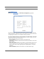
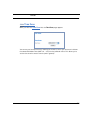
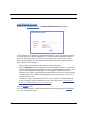
Once you enter your User Name and Password here, you will no longer need to enter
them whenever you access the Internet. The Netopia Gateway stores this information
and automatically connects you to the Internet.
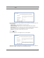
Once a connection is established, your browser is redirected to the Gateway’s homepage which shows the connection status.
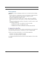
Configure the Netopia Gateway
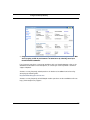
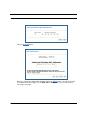
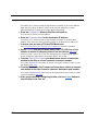
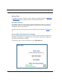
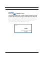
3.
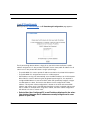
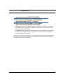
Congratulations! Your installation is complete. You can now surf to your favorite Web
sites by typing an URL in your browser’s location box or by selecting one of your
favorite Internet bookmarks.
If you have any questions or encounter problems with your Netopia Gateway, refer to the
detailed documentation on the Netopia CD, or contact your service provider’s technical
support helpdesk.
Answers to many frequently asked questions in relation to broadband can be found by
accessing the following URL:
http://broadbandsupport.eircom.net
Answers to many frequently asked Netopia modem questions are also available on-line at:
http://www.netopia.com/support.
29
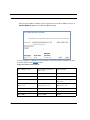
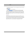
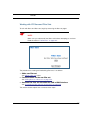
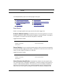
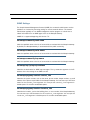
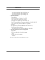
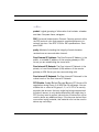
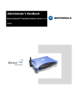
Netopia Gateway Status Indicator Lights
Colored LEDs on your Netopia Gateway indicate the status of various port activity. Different
Gateway models have different ports for your connections and different indicator LEDs.
The Quickstart Guide accompanying your Netopia Gateway describes the behavior of the
various indicator LEDs. Also, see “Basic Troubleshooting” on page 161 for more information.
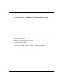
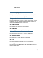
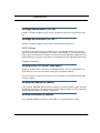
Netopia Gateway 3347W or WG/3357W or WG Wi-Fi Gateway series status indicator lights
3347W/3357W Front View
Power - Green when power is applied
DSL SYNC Flashes green when training
Solid green when trained
LAN 1, 2, 3, 4 Solid green when connected
to each port on the LAN.
Flash green when there is
activity on each port.
Wireless Link - Flashes green when there is
activity on the wireless LAN.
30
Netopia Gateway Status Indicator Lights
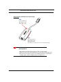
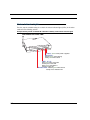
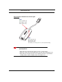
Netopia Gateway 3342/3352 status indicator lights
USB:
L
DS
US
B
Green, USB link up
Off, USB link down
Blink, USB activity
DSL:
Green, DSL link up
Off, DSL link down
Blink, DSL activity
Slow flash (1 second green 1 second off), DSL training
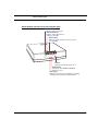
☛
Special patterns:
• Both LEDs are off during boot (power on boot or warm reboot).
• When the 3342/3352 successfully boots up, both LEDs flash green once.
• Both LEDs are off when the Host OS suspends the device, (e.g. Windows
standby/reboot, device disabled, driver uninstalled, etc.)
31
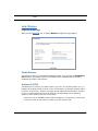
Accessing the Web User Interface
After you have performed the basic Quickstart configuration, any time you log in to your
Netopia Gateway you will access the Netopia Gateway Home page.
You access the Home Page by typing http://192.168.1.254 in your Web browser’s location box.
After entering your Administrative password, the Basic Mode Home Page appears.
The links in the left-hand column on this page allow you to manage or configure several features of your Gateway. Each link is described in its own section.
32
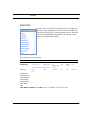
Links Bar
Links Bar
The Links Bar is the frame at the left-hand side of the
page containing the major navigation links. These
links are available from almost every page, allowing
you to move freely about the site. The headings in the
following table are hyperlinks. You can click on any
heading to read about that feature.
Home
Firewall
Wireless
Gaming
Expert Mode
Troubleshoot
Diagnostics
Statistics
Access Control (only appears if configured in
Login
Expert Mode)
Help
33
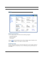
Home
Home Page Information
The Home page displays information about the following categories:
• Connection Information
• Router Information
• Local Network
Click the Help link in the left-hand column of links to display a page of explanatory information. Help is available for every page in the Web interface.
Home Page Links
The links in the left-hand column of the Home page access a series of pages to allow you
to monitor, diagnose, and update your router. The following sections give descriptions of
these pages.
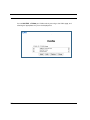
34
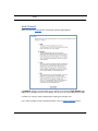
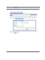
Home
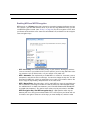
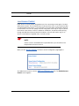
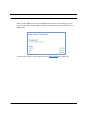
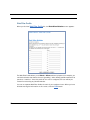
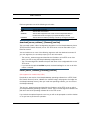
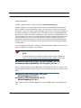
Link: Firewall
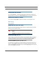
When you click the Firewall link, the Firewall selection page appears.
The Medium setting is recommended, but for special circumstances, High, Medium, and
Low levels of firewall protection are available. You can also turn all firewall protection Off.
Consider your security needs carefully before making any changes here.
If you select a different level of firewall protection, click the Save Changes button.
35
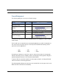
Firewall Background
The following table gives some tips for Firewall settings:
Application
Typical Internet usage
(browsing, e-mail)
Multi-player online
gaming
Going on vacation
Finished online use for the
day
Chatting online or using
instant messaging
Select this
Level
Medium
Low
High
High
Off
Other Considerations
Set up “Gaming” on page 51; once defined,
services will be active whenever Off is set.
Restore Medium when finished.
Protects your connection while you’re away.
This protects you instead of disconnecting
your Gateway connection.
Set up “Gaming” on page 51; once defined,
services will be active whenever Off is set.
Restore Medium when finished.
As a device on the Internet, a Netopia Gateway requires an IP address in order to send or
receive traffic.
The IP traffic sent or received have an associated application port which is dependent on
the nature of the connection request. In the IP protocol standard the following session
types are common applications:
• ICMP
• SNMP
• HTTP
• telnet
• FTP
• DHCP
By receiving a response to a scan from a port or series of ports (which is the expected
behavior according to the IP standard), hackers can identify an existing device and gain a
potential opening for access to an internet-connected device.
To protect LAN users and their network from these types of attacks, the Netopia Firewall
offers three levels of increasing protection.
The following tables indicate the state of ports associated with session types, both on the
WAN side and the LAN side of the Gateway.
36
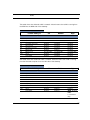
Home
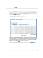
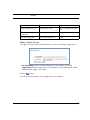
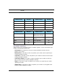
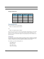
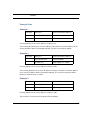
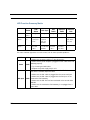
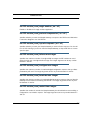
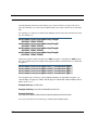
This table shows how inbound traffic is treated. Inbound means the traffic is coming from
the WAN into the WAN side of the Gateway.
Gateway: WAN Side
Firewall Setting >>
Port
20
21
23
23
80
80
67
68
161
Session Type
ftp data
ftp control
telnet external
telnet Netopia server
http external
http Netopia server
DHCP client
DHCP server
snmp
ping (ICMP)
Off
Medium
High
--------------Port State----------------------Enabled
Enabled
Enabled
Enabled
Enabled
Enabled
Enabled
Not Applicable
Enabled
Enabled
Disabled
Disabled
Disabled
Disabled
Disabled
Disabled
Enabled
Not Applicable
Disabled
Disabled
Disabled
Disabled
Disabled
Disabled
Disabled
Disabled
Disabled
Not Applicable
Disabled
Disabled
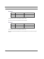
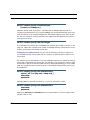
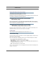
This table shows how outbound traffic is treated. Outbound means the traffic is coming
from the LAN-side computers into the LAN side of the Gateway.
Gateway: LAN Side
Firewall Setting >>
Port
20
21
23
23
80
80
67
68
161
Session Type
ftp data
ftp control
telnet external
telnet Netopia server
http external
http Netopia server
DHCP client
DHCP server
snmp
ping (ICMP)
Off
Medium
High
--------------Port State----------------------Enabled
Enabled
Enabled
Enabled
Enabled
Enabled
Not Applicable
Enabled
Enabled
Enabled
Enabled
Enabled
Enabled
Enabled
Enabled
Enabled
Not Applicable
Enabled
Enabled
Enabled
Disabled
Disabled
Disabled
Enabled
Disabled
Enabled
Not Applicable
Enabled
Enabled
WAN - Disabled
LAN Local Address
Only
37
☛
NOTES:
• The Gateway’s WAN DHCP client port in Medium mode is enabled. This feature allows end users to continue using DHCP-served IP addresses from their
Service Providers, while having no identifiable presence on the Internet.
• Increased Stateful Firewall features are configurable in the CLI. See “Stateful Inspection” on page 220 for more information.
38
Home
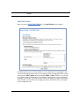
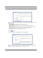
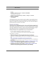
Link: Wireless
(supported models only)
When you click Wireless, the 3-D Reach Wireless configuration page appears.
Enable Wireless
The wireless function is automatically enabled by default. If you uncheck the Enable Wireless checkbox, the Wireless Options are disabled, and the Gateway will not provide or
broadcast any wireless LAN services.
Wireless ID (SSID)
The Wireless ID is preset to a number unique to your unit. You can either leave it as is, or
change it by entering a freeform name of up to 32 characters, for example “Hercule’s Wireless LAN”. On client PCs’ software, this might also be called the Network Name. The Wireless ID is used to identify this particular wireless LAN. Depending on their operating
system or client wireless card, users must either:
• select from a list of available wireless LANs that appear in a scanned list on their client
• or enter this name on their clients in order to join this wireless LAN.
39
Privacy
By default, Privacy is set to On - Manual. This setting uses a preconfigured encryption
key for your convenience.
IT IS STRONGLY RECOMMENDED THAT YOU NOT DISABLE PRIVACY. If you wish other
options than the default, you can access Advanced Configuration Options. See Advanced
Configuration Options (optional) below.
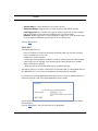
Advanced Configuration Options (optional)
When you click the Advanced Configuration Options button, the Advanced 802.11
Wireless screen appears. This screen varies its options depending on which form of wireless Privacy you have selected.
40
Home
Enable Multiple Wireless IDs
This feature allows you to add additional network identifiers (SSIDs or Network Names) for
your wireless network. To enable it, check the checkbox. The screen expands to allow you
to add up to two additional Wireless IDs.
41
These additional Wireless IDs are “Closed System Mode” Wireless IDs (see below) that
will not be shown by a client scan, and therefore must be manually configured at the client.
In addition, wireless bridging between clients is disabled for all members of these additional network IDs.
☛
NOTE:
The Gateway supports up to 3 different SSIDs:
• One SSID which is broadcast by default and has wireless bridging
enabled by default
• Two additional SSIDs which are in “Closed System Mode” and have
wireless bridging disabled.
These network IDs cannot be configured separately in terms of privacy and
MAC Address filtering. You cannot enable WEP and MAC Address filtering on
one SSID and disable them on another SSID.
Default Channel
(1 through 13, depending on your location) on which the network will broadcast. This is a
frequency range within the 2.4Ghz band. Channel selection depends on government regulated radio frequencies that vary from region to region. The widest range available is from
1 to 14. However, in North America only 1 to 11 may be selected. Europe, France, Spain
and Japan differ. Channel selection can have a significant impact on performance, depending on other wireless activity close to this Router. Channel selection is not necessary at
the client computers; the clients will scan the available channels seeking access points
using the same SSID as the client.
Enable Closed System Mode
If enabled, Closed System Mode hides the wireless network from the scanning features of
wireless client computers. Unless both the wireless clients and the Router share the same
42
Home
Wireless ID in Closed System mode, the Router’s wireless LAN will not appear as an available network when scanned for by wireless-enabled computers. Members of the Closed
System WLAN must log onto the Router’s wireless network with the identical SSID as that
configured in the router.
Closed System mode is an ideal way to increase wireless security and to prevent casual
detection by unwanted neighbors, office users, or malicious users such as hackers.
If you do not enable Closed System Mode, it is more convenient, but potentially less
secure, for clients to access your WLAN by scanning available access points. You must
decide based on your own network requirements.
About Closed System Mode and Wireless Encryption
Enabling Closed System Mode on your wireless Router provides another level of security,
since your wireless LAN will no longer appear as an available access point to client PCs
that are casually scanning for one.
Your own wireless network clients, however, must log into the wireless LAN by using the
exact SSID of the Netopia Router.
In addition, if you have enabled WEP or WPA encryption on the Netopia Router, your network clients must also have WEP or WPA encryption enabled, and must have the same
WEP or WPA encryption key as the Netopia Router.
Once the Netopia Gateway is located by a client computer, by setting the client to a matching SSID, the client can connect immediately if WEP or WPA is not enabled. If WEP or WPA
is enabled then the client must also have WEP or WPA enabled and a matching WEP or WPA
key.
Wireless client cards from different manufacturers and different operating systems accomplish connecting to a wireless LAN and enabling WEP or WPA in a variety of ways. Consult
the documentation for your particular wireless card and/or operating system.
Block Wireless Bridging
Check the checkbox to block wireless clients from communicating with other wireless clients on the LAN side of the Gateway.
43
Enabling WPA and WEP Encryption
WEP Security is a Privacy option that is based on encryption between the Router and any
PCs (“clients”) you have with wireless cards. If you are not using WPA-PSK Privacy, you can
use WEP Encryption instead. (See “Privacy” on page 40.) For this encryption to work, both
your Router and each client must share the same Wireless ID, and both must be using the
same encryption keys.
• OFF - No Privacy: This mode disables privacy on your network, allowing any wireless
users to connect to your wireless LAN. Use this option if you are using alternative security measures such as VPN tunnels, or if your network is for public use.
• WEP - Automatic: The simplest way to enable WEP is to select On - Automatic, enter a
passphrase, and click the link to make keys. You can also change the key size. This will
generate four WEP keys, which you would then set on each of your wireless clients. Be
sure to copy the keys exactly, and place them in the same slots!
• WEP - Manual Entry: Encryption Keys 1-4: For each WEP key, enter the specified number of characters consisting of numbers 0-9 and the letters A-F. Valid examples would
be “941BC12A21” for 40bit (10 characters), and “F12345678A0123456789ABCDEF”
for 128bit (26 characters). You need to enter at least one key and select it with Use
WEP Encryption Key. Use WEP encryption key (1 – 4) # specifies which key the
Gateway will use to encrypt transmitted traffic. This is the key that your Router will use
for wireless encryption. Select one of the keys you have already set, and then make
44
Home
sure that the client wireless PC is also using the same matching key. The default is key
#1.
• WPA-802.1x provides RADIUS server authentication support. See RADIUS Server
authentication below.
• WPA-PSK provides Wireless Protected Access, the most secure option for your wireless network. See “WPA-PSK” on page 47. This mechanism provides the best data protection and access control.
Be sure that your Wi-Fi client adapter supports this option. Not all Wi-Fi clients support
WPA-PSK.
RADIUS Server authentication
RADIUS servers allow external authentication of users by means of a remote authentication database. The remote authentication database is maintained by a Remote Authentication Dial-In User Service (RADIUS) server. In conjunction with Wireless User Authentication,
you can use a RADIUS server database to authenticate users seeking access to the wireless services, as well as the authorized user list maintained locally within the Gateway.
If you select WPA-802.1x, the screen expands to allow you to enter your RADIUS server
information.
45
• RADIUS Server Addr/Name: The default RADIUS server name or IP address that you
want to use.
• RADIUS Server Secret: The RADIUS secret key used by this server. The shared secret
should have the same characteristics as a normal password.
• Alt RADIUS Server Addr/Name: An alternate RADIUS server name or IP address, if
available.
• Alt RADIUS Server Secret: The RADIUS secret key used by this alternate server. The
shared secret should have the same characteristics as a normal password.
• RADIUS Server Port: The port on which the RADIUS server is listening, typically, the
default 1812.
Click the Save Changes button.
46
Home
WPA-PSK
One of the easiest ways to enable Privacy on your Wireless network is by selecting
WPA-PSK (Wi-Fi Protected Access) from the pull-down menu.
The screen expands to allow you to enter a Pre Shared Key. The key can be between 8
and 63 characters, but for best security it should be at least 20 characters. When you have
entered your key, click the Save Changes button.
Alternatively, you can enable WEP (Wired Equivalent Privacy) encryption by selecting
WEP-Automatic from the Privacy pull-down menu.
47
You can provide a level of data security by enabling WEP (Wired Equivalent Privacy) for
encryption of network data. You can enable 40-, 128-, or 256-bit WEP Encryption (depending on the capability of your client wireless card) for IP traffic on your LAN.
Enter a Passphrase. The number of characters to use is shown in the pull-down menu.
Click the click Save Changes button. This will generate an encryption key automatically.
Any WEP-enabled client must have an identical key of the same length as the Router, in
order to successfully receive and decrypt the traffic. Similarly, the client also has a
‘default’ key that it uses to encrypt its transmissions. In order for the Router to receive the
client’s data, it must likewise have the identical key of the same length.
Wireless MAC Authorization (optional)
MAC Authorization allows you to specify which client PCs are allowed to join the wireless
LAN by unique hardware (MAC) address. To enable this feature, click the Limit Wireless
Access by MAC Address button. The MAC Authorization screen appears.
48
Home
Select Enabled from the pull-down menu.
The screen expands to permit you to add MAC addresses.
Click the Add button.
Once it is enabled, only entered MAC addresses that have been set to Allow will be
accepted onto the wireless LAN. All unlisted addresses will be blocked, in addition to the
listed addresses with Allow disabled.
49
Click the Submit button.
When you are finished adding MAC addresses click the Done button. You will be returned
to the 802.11 Wireless page. You can Add, Edit, or Delete any of your entries later by
returning to this page.
50
Home
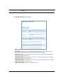
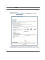
Link: Gaming
When you click Gaming, the NAT (Games and Other Services) page appears.
NAT (Games and Other Services) allows you to host internet applications when NAT is
enabled. You can host different games and software on different PCs.
From the Service Name pull-down menu, you can select any of a large number of predefined games and software. (See “Supported Games and Software” on page 52.)
1.
Once you choose a software service or game, click Enable.
The Enable Service screen appears.
Select Host Device specifies the machine on which the selected software is hosted.
2.
Select a PC to host the software from the Select Host Device pull-down
menu and click Enable.
51
Each time you enable a software service or game your entry will be added to the list of
Service Names displayed on the NAT Configuration page.
To remove a game or software from the hosted list, choose the game or software you want
to remove and click the Disable button.
Supported Games and Software
52
Age of Empires, v.1.0
Age of Empires: The Rise of
Rome, v.1.0
Age of Wonders
Asheron's Call
Baldur's Gate
Battlefield Communicator
Buddy Phone
Calista IP Phone
CART Precision Racing, v 1.0
Citrix Metaframe/ICA Client
Close Combat for Windows 1.0
Close Combat: A Bridge Too
Far, v 2.0
Close Combat III: The Russian
Front, v 1.0
Combat Flight Sim: WWII
Europe Series, v 1.0
Combat Flight Sim 2: WWII
Pacific Thr, v 1.0
Dark Reign
Delta Force (Client and Server)
Delta Force 2
Diablo II Server
Dialpad
DNS Server
Dune 2000
eDonkey 2000
eMule
Home
F-16, Mig 29
F-22, Lightning 3
Fighter Ace II
FTP
GNUtella
H.323 compliant (Netmeeting,
CUSeeME)
Half Life
Hellbender for Windows, v 1.0
Heretic II
Hexen II
Hotline Server
HTTP
HTTPS
ICQ 2001b
ICQ Old
IMAP Client
IMAP Client v.3
Internet Phone
IPSec
IPSec IKE
Jedi Knight II: Jedi Outcast
Kali
KazaA
LimeWire
Links LS 2000
Mech Warrior 3
Mech Warrior 4: Vengeance
Medal of Honor Allied Assault
Microsoft Flight Simulator 98
Microsoft Flight Simulator
2000
Microsoft Golf 1998 Edition, v
1.0
Microsoft Golf 1999 Edition
Microsoft Golf 2001 Edition
Midtown Madness, v 1.0
Monster Truck Madness, v 1.0
Monster Truck Madness 2, v
2.0
Motocross Madness 2, v 2.0
Motocross Madness, v 1.0
MSN Game Zone
MSN Game Zone (DX7 an 8
Play)
Need for Speed 3, Hot Pursuit
Need for Speed, Porsche
Net2Phone
NNTP
Operation FlashPoint
Outlaws
pcAnywhere (incoming)
POP-3
PPTP
Quake II
Quake III
Rainbow Six
RealAudio
Return to Castle Wolfenstein
Roger Wilco
Rogue Spear
ShoutCast Server
SMTP
SNMP
SSH server
StarCraft
Starfleet Command
StarLancer, v 1.0
Telnet
TFTP
Tiberian Sun: Command and
Conquer
53
Timbuktu
Total Annihilation
Ultima Online
Unreal Tournament Server
Urban Assault, v 1.0
VNC, Virtual Network Computing
Westwood Online, Command
and Conquer
Win2000 Terminal Server
XBox Live Games
Yahoo Messenger Chat
Yahoo Messenger Phone
ZNES
Define Custom Service
To configure a Custom Service, choose whether to use Port Forwarding or Trigger Ports.
• Port Forwarding forwards a range of WAN ports to an IP address on the LAN.
• Trigger Ports forwards a range of ports to an IP address on the LAN only after specific
outbound traffic “triggers” the feature.
Click the Next button.
If you chose Port Forwarding, the Port Range entry screen appears.
54
Home
Port Forwarding forwards a range of WAN ports to an IP address on the LAN. Enter the following information:
• Service Name: A unique identifier for the Custom Service.
• Global Port Range: Range of ports on which incoming traffic will be received.
• Base Host Port: The port number at the start of the port range your Router should use
when forwarding traffic of the specified type(s) to the internal IP address.
• Protocol: Protocol type of Internet traffic, TCP or UDP.
Click the Next button.
If you chose Trigger Ports, the Trigger Ports entry screen appears.
Trigger Ports forwards a range of ports to an IP address on the LAN only after specific outbound traffic “triggers” the feature. Enter the following information:
55
• Service Name: A unique identifier for the Custom Service.
• Global Port Range: Range of ports on which incoming traffic will be received.
• Local Trigger Port: Port number of the type of outbound traffic that needs to happen
(will be the trigger) to then allow the configured ports for inbound traffic.
Example: Set the trigger port to 21 and configure a range of 25 – 110. You would need
to do an outbound ftp before you were able to do an inbound smtp.
Click the Next button.
Static NAT
This feature allows you to:
• Direct your Router to forward all externally initiated IP traffic (TCP and UDP protocols
only) to a default host on the LAN.
• Enable it for certain situations:
– Where you cannot anticipate what port number or packet protocol an in-bound application might use. For example, some network games select arbitrary port numbers
when a connection is opened.
– When you want all unsolicited traffic to go to a specific LAN host.
This feature allows you to direct unsolicited or non-specific traffic to a designated LAN station. With NAT “On” in the Router, these packets normally would be discarded.
For instance, this could be application traffic where you don’t know (in advance) the port or
protocol that will be used. Some game applications fit this profile.
From the pull-down menu, select the address of the PC that you want to be your default
NAT destination.
Click the Next button, and your choice will be so designated.
56
Home
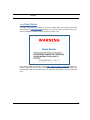
Link: Expert Mode
Expert Mode allows you to configure a wide variety of specific Router and networking settings. Expert Mode is for advanced users and system administrators, and most users will
not need to modify these settings. If you need to enter Expert Mode, and click the Expert
Mode link, you will be challenged to confirm your choice.
57
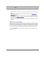
Link: Troubleshoot
When you click the Troubleshoot link, the Links Bar expands to offer two troubleshooting
sub-headings: Diagnostics and Statistics.
Diagnostics
This automated multi-layer test examines the functionality of the Router from the physical
connections to the data traffic being sent by users through the Router.
You enter a web address, such as tftp.netopia.com, or an IP address in the Web Address
field and click the Test button. Results will be displayed in the Progress Window as they
are generated.
This sequence of tests takes approximately one minute to generate results. Please wait for
the test to run to completion.
58
Home
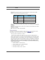
Each test generates one of the following result codes:
Result
* PASS:
Meaning
The test was successful.
* FAIL:
The test was unsuccessful.
* SKIPPED:
The test was skipped because a test on which it depended failed.
* PENDING:
The test timed out without producing a result. Try running Diagnostics again.
* WARNING:
The test was unsuccessful. The Service Provider equipment your Router connects to may not support this test.
Statistics
When you click the Statistics link, the Links Bar expands to display seven statistical subheadings: DSL, ATM, Ethernet (supported models only), IP, LAN, Wireless (supported models only), and Logs. These screens will vary depending on your Gateway’s model and traffic
activity.
DSL
When you click DSL, the DSL Statistics page appears.
The DSL Statistics page displays information about the Router's WAN connection to the
Internet.
• Line State: May be Up (connected) or Down (disconnected).
• Modulation: Method of regulating the DSL signal. DMT (Discrete MultiTone) allows connections to work better when certain radio transmitters are present.
• Data Path: Type of path used by the device's processor.
Downstream and Upstream statistics
• Max Allowed Speed (kbps): Your maximum speeds for downloading (receiving) and
uploading (sending) data on the DSL line, in kilobits per second.
• SN Margin (db): Signal to noise margin, in decibels. Reflects the amount of unwanted
“noise” on the DSL line.
• Line Attenuation: Amount of reduction in signal strength on the DSL line, in decibels.
• CRC Errors: Number of times data packets have had to be resent due to errors in
transmission or reception.
59
ATM
When you click ATM, the ATM Statistics page appears.
The ATM Statistics page displays detailed statistics about the upstream and downstream
data traffic handled by your Router. Displays the Virtual Circuit (VPI/VCI) settings as well as
information about your PPPoE session if operating in PPPoE mode. This information is useful for troubleshooting and when seeking technical support.
Ethernet (supported models only)
When you click Ethernet, the Ethernet Statistics page appears.
The Ethernet Statistics page:
• displays your Router's unique hardware (MAC) address.
• displays detailed statistics about your LAN data traffic, upstream and downstream.
IP
When you click IP, the IP Statistics page appears. The IP Statistics page displays the IP
interfaces and routing table information about your network.
General
• IP WAN Address: The public IP address of your Router, whether dynamically or statically assigned.
• IP Gateway: Your ISP's gateway router IP address
• Primary DNS: The IP address of the Primary Domain Name Server
• Primary DNS name: The name of the Primary Domain Name Server
• Secondary DNS: The IP address of the backup Domain Name Server (if any)
• Secondary DNS name: The name of the backup Domain Name Server (if any)
IP interfaces
• Address: Your Router's IP address as seen from your internal network (LAN), and from
the public Internet (WAN)
• Netmask: The subnet mask for the respective IP interfaces (LAN and WAN)
• Name: The name of each IP interface (example:Eth0, WAN1)
60
Home
Network Routing Table and Host Routing Table
The Routing tables display all of the IP routes currently known to your Router.
LAN
When you click LAN, the LAN Statistics page appears.
The LAN Statistics page displays detailed information about your LAN IP configuration and
names and IP addresses of devices on your LAN.
• Router IP Address: The IP address of your Router as seen from the LAN
• DHCP Netmask: Subnet mask of your LAN
• DHCP Start Address: First IP address in the range being served to your LAN by the
Router's DHCP server
• DHCP End Address: Last IP address in the range being served to your LAN by the
Router's DHCP server
• DHCP Server Status: May be On or Off
• DNS Server: The IP address of the default DNS server
Devices on LAN
Displays the IP Address, MAC (hardware) Address, and network Name for each device on
your LAN connected to the Router.
Wireless (supported models only)
When you click Wireless, the Wireless Statistics page appears.
The Wireless Statistics page:
• displays your Router's unique hardware Wireless (MAC) address.
• displays detailed statistics about your Wireless LAN data traffic, upstream and downstream.
USB (supported models only)
When you click USB, the USB Statistics page appears.
The USB Statistics page:
• displays your Router's unique hardware (MAC) address.
• displays detailed statistics about your LAN data traffic, upstream and downstream.
61
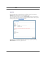
Logs
When you click Logs, the Logs page appears.
Select a log from the pull-down menu (the pull-down menu is available from every Log
page):
• All: Displays the entire system log.
• Connection: Displays events logged for the WAN connection.
• System: Displays events logged for the Router system configuration.
The CURRENT Router STATUS is displayed for all logs.
• To clear the individual logs, click the Clear Log button for that page.
• To clear all the logs, click the Clear All Logs button on the main Logs page.
62
Home
Link: Access Control Login
If you have configured the onboard Access Control feature (see “Access Control” on
page 85) your authorized users must log in to be able to use the Internet.
If you have not configured Access Control, this link does not appear in the Links Bar.
When you click Access Control Login, the Access Control Login page appears.
Users must select their Username from the pull-down menu, and enter their Password,
then click the Login button.
63
Link: Help
When you click the Help link in the left-hand column of links a page of explanatory information displays. Help (in English only) is available for every page in the Web interface.
Here is an example from the Home page:
64
Access the Expert Web Interface
CHAPTER 3
Expert Mode
Using the Web-based user interface for the Netopia 3300-series Gateway you can configure, troubleshoot, and monitor the status of your Gateway.
Access the Expert Web Interface
Open the Web Connection
Once your Gateway is powered up, you can use any recent version of the best-known web
browsers such as Netscape Navigator or Microsoft Internet Explorer from any LAN-attached
PC or workstation. The procedure is:
1.
2.
Enter the name or IP address of your Netopia Gateway in the Web browser's window
and press Return.
For example, you would enter http://192.168.1.254.
If an administrator or user password has been assigned to the Netopia Gateway,
enter Admin or User as the username and the appropriate password and click OK.
The Basic Mode Home Page opens.
65
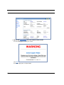
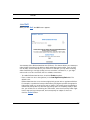
3.
Click on the Expert Mode link in the left-hand column of links.
You are challenged to confirm your choice.
Click OK.
The Home Page opens in Expert Mode.
66
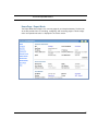
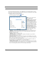
Access the Expert Web Interface
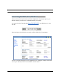
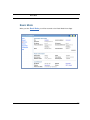
Home Page - Expert Mode
The Expert Mode Home Page is the summary page for your Netopia Gateway. The links bar
at the left provides links to controlling, configuring, and monitoring pages. Critical configuration and operational status is displayed in the center section.
67
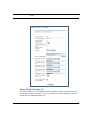
Home Page - Information
The Home Page contains a summary of the Gateway’s configuration settings and status.
Summary Information
Field
Status and/or Description
Connection Information
DSL/WAN Status
Connection
User Name
IP Address
IP Gateway
Primary and
Secondary DNS
Server
Speed
Line Attenuation
Restart Connection button
Connect button
Wide Area Network may be Waiting for DSL (or other waiting status), Up or Down
Up or Down
Your ISP-assigned Username
IP address assigned to the WAN port.
The IP address of the gateway to which the connection defaults. If doing DHCP, this
info will be acquired. If doing PPP, this info will be negotiated.
Address(es) of your ISP's Domain Name Server(s).
Your upstream and downstream data rates
amount of attenuation on your phone lines.
allows you to attempt to reconnect using the same login credentials as your current
connection.
allows you to reconnect using a different User Name and Password. This button is
only available if you are not connected.
Disconnect button allows you to disconnect your current connection. This button is only available if a
connection is established.
Router Information
Router Name and
Model
Serial Number
MAC Address
Software Version
Warranty Date
Your Router's manufacturing information
Your Router's unique serial number. Usually also printed on the Router's label.
Your Router's unique hardware address
The version of embedded operating system software currently running on the Gateway.
Original date when your Gateway is first connected and gets the time via the network,
for warranty purposes.
Local Network
IP Address
Ethernet
USB
68
The IP address of your Router as seen from your internal LAN
Status of your Ethernet network connection (if supported). Connected or Not Connected.
Status of your USB network connection (if supported). Connected or Not Connected.
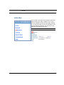
Links Bar
Links Bar
The Links Bar is the frame at the left-hand side of the page containing the major navigation links. These links are available from
every page, allowing you to move freely about the site. The headings in the following table are hyperlinks. You can click on any
heading to read about that feature.
This chapter covers the following:
Expert Mode
Configure
(Advanced)
Statistics
Connection
Access Control
Wireless
DHCP Server
Router Password
DSL
Logs
Time Zone
ATM
IP
NAT
Passthrough
VLAN
Ethernet
IP
Packet
Filter
QoS
LAN
Wireless
Diagnostics
Remote Access
Update Router
Reset Router
Restart Router
Basic Mode
Help
Note: Ethernet, Wireless, and USB links are only available on supported models.
69
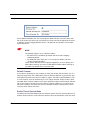
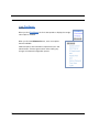
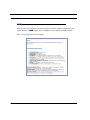
Link: Configure
When you click Configure, the Links bar expands to display the configuration options available.
When you click the Advanced button, even more options
become available.
Advanced options are intended for experienced users and
administrators. Exercise great caution when making any
changes to Advanced Configuration options.
70
Links Bar
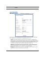
Link: Connection
When you click Connection, the Connection Configuration page appears.
Here you can set up or change the way you connect to your ISP. You should only change
these settings at your ISP's direction, or by agreement with your ISP.
• VPI/VCI: These values depend on the way your ISP's equipment is configured. The
default setting is 0/0, auto-detection. With this setting, the router will attempt to detect
what settings your ISP is using, with no input on your part. You probably would not need
to change this. 8/35 and 0/35 are also common virtual circuit pairs, but others are
sometimes used. Check with your ISP before making any changes here.
• Protocol: The authentication and encapsulation protocol is determined by your ISP,
often by the type of account that you have signed up for. Options here are PPPOE LLC,
PPPOE VCMUX, ETHER LLC, IP LLC, PPPOA LLC, and PPPOA VCMUX.
• Bridging: Your Router can be turned into a simple bridge, if desired. However, it will no
longer provide routing or security features in this mode.
71
• User ID and Password: Provided by your ISP.
• Confirm Password: Repeat your Password entry for confirmation
• Static IP Address: Your service provider may tell you that the WAN IP Address for your
•
•
•
•
•
Router is static. In this case, enter the IP Address from your Service Provider in the
appropriate field.
IP Gateway: The IP Address of the default gateway, or peer address if using PPP. This
is normally set to 0.0.0.0 for PPP connections.
Primary DNS Server: The IP Address of the Primary Domain Name Server
Secondary DNS Server: The IP Address of the backup Domain Name Server
Connection Type: If using PPPoE, this is a choice to have either an uninterrupted connection or an as-needed connection. The type of service you have signed up for with
your ISP. Options are On-Demand, Always ON, and Manual.
Always On: This setting provides convenience, but it leaves your network permanently
connected to the Internet.
On-Demand: Furnishes almost all the benefits of an Always On connection, but has
additional security benefits:
Your network cannot be attacked when it is not connected.
Your network may change address with each connection, making it more difficult to
attack.
Manual: This setting disables automatic connection attempts. The user must bring the
connection up and down via the Connect/Disconnect buttons.
UPnP: Universal Plug and Play (UPnP™) is a set of protocols that allows a PC to automatically discover other UPnP devices (anything from an internet gateway device to a
light switch), retrieve an XML description of the device and its services, control the
device, and subscribe to real-time event notification. By default, UPnP is enabled on the
Netopia Gateway.
For Windows XP users, the automatic discovery feature places an icon representing the
Netopia Gateway automatically in the “My Network Places” folder. Double-clicking this
icon opens the Gateway’s web UI.
PCs using UPnP can retrieve the Gateway’s WAN IP address, and automatically create
NAT port maps. This means that applications that support UPnP, and are used with a
UPnP-enabled Netopia Gateway, will not need application layer gateway support on the
Netopia Gateway to work through NAT.
You can disable UPnP, if you are not using any UPnP devices or applications. Uncheck
the UPnP Enabled checkbox.
When all of your entries are made, click the Save Changes button.
72
Links Bar
Link: Wireless
(supported models only)
When you click Wireless, the 3-D Reach Wireless configuration page appears.
Enable Wireless
The wireless function is automatically enabled by default. If you uncheck the Enable Wireless checkbox, the Wireless Options are disabled, and the Gateway will not provide or
broadcast any wireless LAN services.
Wireless ID (SSID)
The Wireless ID is preset to a number unique to your unit. You can either leave it as is, or
change it by entering a freeform name of up to 32 characters, for example “Hercule’s Wireless LAN”. On client PCs’ software, this might also be called the Network Name. The Wireless ID is used to identify this particular wireless LAN. Depending on their operating
system or client wireless card, users must either:
• select from a list of available wireless LANs that appear in a scanned list on their client
• or enter this name on their clients in order to join this wireless LAN.
73
Privacy
By default, Privacy is set to On - Manual. This setting uses a preconfigured encryption
key for your convenience.
IT IS STRONGLY RECOMMENDED THAT YOU NOT DISABLE PRIVACY. If you wish other
options than the default, you can access Advanced Configuration Options. See Advanced
Configuration Options (optional) below.
Advanced Configuration Options (optional)
When you click the Advanced Configuration Options button, the Advanced 802.11
Wireless screen appears. This screen varies its options depending on which form of wireless Privacy you have selected.
74
Links Bar
Enable Multiple Wireless IDs
This feature allows you to add additional network identifiers (SSIDs or Network Names) for
your wireless network. To enable it, check the checkbox. The screen expands to allow you
to add up to two additional Wireless IDs.
75
These additional Wireless IDs are “Closed System Mode” Wireless IDs (see below) that
will not be shown by a client scan, and therefore must be manually configured at the client.
In addition, wireless bridging between clients is disabled for all members of these additional network IDs.
☛
NOTE:
The Gateway supports up to 3 different SSIDs:
• One SSID which is broadcast by default and has wireless bridging
enabled by default
• Two additional SSIDs which are in “Closed System Mode” and have
wireless bridging disabled.
These network IDs cannot be configured separately in terms of privacy and
MAC Address filtering. You cannot enable WEP and MAC Address filtering on
one SSID and disable them on another SSID.
Default Channel
(1 through 13, depending on your location) on which the network will broadcast. This is a
frequency range within the 2.4Ghz band. Channel selection depends on government regulated radio frequencies that vary from region to region. The widest range available is from
1 to 14. However, in North America only 1 to 11 may be selected. Europe, France, Spain
and Japan differ. Channel selection can have a significant impact on performance, depending on other wireless activity close to this Router. Channel selection is not necessary at
the client computers; the clients will scan the available channels seeking access points
using the same SSID as the client.
Enable Closed System Mode
If enabled, Closed System Mode hides the wireless network from the scanning features of
wireless client computers. Unless both the wireless clients and the Router share the same
76
Links Bar
Wireless ID in Closed System mode, the Router’s wireless LAN will not appear as an available network when scanned for by wireless-enabled computers. Members of the Closed
System WLAN must log onto the Router’s wireless network with the identical SSID as that
configured in the router.
Closed System mode is an ideal way to increase wireless security and to prevent casual
detection by unwanted neighbors, office users, or malicious users such as hackers.
If you do not enable Closed System Mode, it is more convenient, but potentially less
secure, for clients to access your WLAN by scanning available access points. You must
decide based on your own network requirements.
About Closed System Mode and Wireless Encryption
Enabling Closed System Mode on your wireless Router provides another level of security,
since your wireless LAN will no longer appear as an available access point to client PCs
that are casually scanning for one.
Your own wireless network clients, however, must log into the wireless LAN by using the
exact SSID of the Netopia Router.
In addition, if you have enabled WEP or WPA encryption on the Netopia Router, your network clients must also have WEP or WPA encryption enabled, and must have the same
WEP or WPA encryption key as the Netopia Router.
Once the Netopia Gateway is located by a client computer, by setting the client to a matching SSID, the client can connect immediately if WEP or WPA is not enabled. If WEP or WPA
is enabled then the client must also have WEP or WPA enabled and a matching WEP or WPA
key.
Wireless client cards from different manufacturers and different operating systems accomplish connecting to a wireless LAN and enabling WEP or WPA in a variety of ways. Consult
the documentation for your particular wireless card and/or operating system.
Block Wireless Bridging
Check the checkbox to block wireless clients from communicating with other wireless clients on the LAN side of the Gateway.
77
Enabling WPA and WEP Encryption
WEP Security is a Privacy option that is based on encryption between the Router and any
PCs (“clients”) you have with wireless cards. If you are not using WPA-PSK Privacy, you can
use WEP Encryption instead. (See “Privacy” on page 74.) For this encryption to work, both
your Router and each client must share the same Wireless ID, and both must be using the
same encryption keys.
• OFF - No Privacy: This mode disables privacy on your network, allowing any wireless
users to connect to your wireless LAN. Use this option if you are using alternative security measures such as VPN tunnels, or if your network is for public use.
• WEP - Automatic: The simplest way to enable WEP is to select On - Automatic, enter a
passphrase, and click the link to make keys. You can also change the key size. This will
generate four WEP keys, which you would then set on each of your wireless clients. Be
sure to copy the keys exactly, and place them in the same slots!
• WEP - Manual Entry: Encryption Keys 1-4: For each WEP key, enter the specified number of characters consisting of numbers 0-9 and the letters A-F. Valid examples would
be “941BC12A21” for 40bit (10 characters), and “F12345678A0123456789ABCDEF”
for 128bit (26 characters). You need to enter at least one key and select it with Use
WEP Encryption Key. Use WEP encryption key (1 – 4) # specifies which key the
Gateway will use to encrypt transmitted traffic. This is the key that your Router will use
for wireless encryption. Select one of the keys you have already set, and then make
78
Links Bar
sure that the client wireless PC is also using the same matching key. The default is key
#1.
• WPA-802.1x provides RADIUS server authentication support. See RADIUS Server
authentication below.
• WPA-PSK provides Wireless Protected Access, the most secure option for your wireless network. See “WPA-PSK” on page 81. This mechanism provides the best data protection and access control.
Be sure that your Wi-Fi client adapter supports this option. Not all Wi-Fi clients support
WPA-PSK.
RADIUS Server authentication
RADIUS servers allow external authentication of users by means of a remote authentication database. The remote authentication database is maintained by a Remote Authentication Dial-In User Service (RADIUS) server. In conjunction with Wireless User Authentication,
you can use a RADIUS server database to authenticate users seeking access to the wireless services, as well as the authorized user list maintained locally within the Gateway.
If you select WPA-802.1x, the screen expands to allow you to enter your RADIUS server
information.
79
• RADIUS Server Addr/Name: The default RADIUS server name or IP address that you
want to use.
• RADIUS Server Secret: The RADIUS secret key used by this server. The shared secret
should have the same characteristics as a normal password.
• Alt RADIUS Server Addr/Name: An alternate RADIUS server name or IP address, if
available.
• Alt RADIUS Server Secret: The RADIUS secret key used by this alternate server. The
shared secret should have the same characteristics as a normal password.
• RADIUS Server Port: The port on which the RADIUS server is listening, typically, the
default 1812.
Click the Save Changes button.
80
Links Bar
WPA-PSK
One of the easiest ways to enable Privacy on your Wireless network is by selecting
WPA-PSK (Wi-Fi Protected Access) from the pull-down menu.
The screen expands to allow you to enter a Pre Shared Key. The key can be between 8
and 63 characters, but for best security it should be at least 20 characters. When you have
entered your key, click the Save Changes button.
Alternatively, you can enable WEP (Wired Equivalent Privacy) encryption by selecting
WEP-Automatic from the Privacy pull-down menu.
81
You can provide a level of data security by enabling WEP (Wired Equivalent Privacy) for
encryption of network data. You can enable 40-, 128-, or 256-bit WEP Encryption (depending on the capability of your client wireless card) for IP traffic on your LAN.
Enter a Passphrase. The number of characters to use is shown in the pull-down menu.
Click the click Save Changes button. This will generate an encryption key automatically.
Any WEP-enabled client must have an identical key of the same length as the Router, in
order to successfully receive and decrypt the traffic. Similarly, the client also has a
‘default’ key that it uses to encrypt its transmissions. In order for the Router to receive the
client’s data, it must likewise have the identical key of the same length.
Wireless MAC Authorization (optional)
MAC Authorization allows you to specify which client PCs are allowed to join the wireless
LAN by unique hardware (MAC) address. To enable this feature, click the Limit Wireless
Access by MAC Address button. The MAC Authorization screen appears.
82
Links Bar
Select Enabled from the pull-down menu.
The screen expands to permit you to add MAC addresses.
Click the Add button.
Once it is enabled, only entered MAC addresses that have been set to Allow will be
accepted onto the wireless LAN. All unlisted addresses will be blocked, in addition to the
listed addresses with Allow disabled.
83
Click the Submit button.
When you are finished adding MAC addresses click the Done button. You will be returned
to the 802.11 Wireless page. You can Add, Edit, or Delete any of your entries later by
returning to this page.
84
Links Bar
Link: Access Control
Basic Access Controls prevent designated users from accessing certain types of undesirable Internet content. You can define levels of maturity of the users on your network to filter
out objectionable web content or communications from potentially undesirable individuals
on the Internet. You can also specify the time of day when users may (or may not) access
the Internet. Once Access Control is enabled on a WAN link, all relevant traffic passing
through the WAN link will be monitored for violations. All users will need to sign on to
Access Control before using Web, chat, or e-mail services.
☛
NOTE:
Access Controls are disabled and superseded when you subscribe to the
Netopia Parental Control service.
When you click Access Control, the Access Control configuration page appears.
To enable Access Control, click the PPP over Ethernet vcc1 link. The Enable Access
Control screen appears.
85
Check the Enable Access Control checkbox and click the Submit button.
Return to the Access Control configuration page. Click the Setup link in Access Control
Options. The Access Control - User Manager screen appears.
Click the here link. The Add New User screen appears.
86
Links Bar
Here you can add the names and passwords of authorized users, and set their “Maturity
Level” from the pull-down menu. Available maturity levels are Child, Youth, Mature, and
Adult. Click the Next button. The Time of Day Settings screen appears. Maturity Level
only affects Time of Day Settings.
You can create up to a maximum of eight (8) users.
Here you can specify the time of day, day(s) of the week, and whether this user will be permitted or blocked from accessing the Internet at the specified times and days. If you need
to correct the Date and Time settings of your Gateway, you can go directly to the Time
Zone screen by clicking the here link at the top of the page.
When you have finished setting up the criteria for this user, click the Add User button.
87
After you have added your users and configured their access control settings, you can
return to the Access Control pages at any time to add more users, edit existing ones, or
delete them.
To edit a user’s access control settings, click the Edit Profile link for that user.
88
Links Bar
The Edit User Profiles screen appears.
• Manage Users – returns you to the previous screen.
• User Profile – takes you to the User Profile screen where you can change the user’s
password or maturity level setting, and time of day usage settings.
• Web Filter Profile – takes you to the Web Filter Profile screen where you can filter the
websites accessible to this user.
• Chat Filter Profile – takes you to the Chat Filter Profile screen where you can specify
allowable chat partners for this user.
• Email Filter Profile – takes you to the Email Filter Profile screen where you can specify
allowable email partners for this user.
• Delete User Profile – allows you to delete this user.
89
Web Filter Profile
When you click the Web Filter Profile link, the Block/Allow Websites screen appears.
The Web Filter Profile allows you to Block or Allow websites by keyword, for example, you
can block websites that feature the word “gambling,” while allowing specific websites that
pertain to “statistics.” Once this profile for this user is configured, the user will be prevented from accessing any blocked website.
You can set separate Web Filter Profiles for each of your configured users. When you have
finished entering the information on this screen, click the Save button.
90
Links Bar
Chat Filter Profile
When you click the Chat Filter Profile link, the Chat Filtering screen appears.
Chat Filtering allows you to choose whether or not the specified user may engage in Internet instant messaging (chat) by means of the popular instant messaging protocols used by
America Online (AOL), Yahoo, Microsoft Network (MSN), or ICQ. If allowed, you can specify a limited number of individuals by “Screen Name” with whom this user can exchange
messages. For example, if you want to limit a child to exchanging messages only with other
family members, you can allow the messaging service(s), but restrict them to messages
only from approved users.
91
• Messaging Privileges Selection – Choose whether or not this user may use any
instant messaging (chat) service. The default privilege is May not use any instant Messaging service. Click the appropriate radio button.
• Messaging Services – If a chat service is permitted, choose which one(s): AOL,
Yahoo!, MSN, or ICQ. You can choose more than one, but you must choose one at a
time. See below.
• Screen Names List Management –
• For each service, enter the screen name of the approved user in the New Screen
Name field and click the Add button. The Screen name will be added to the Screen
Names List.
• Choose a different Messaging Service by clicking its radio button, enter another
approved user in the New Screen Name field, and click the Add button. The Screen
name will be added to the Screen Names List.
• When you have finished adding approved Screen Names to the list of permitted chat
partners for this user, click the Save button.
92
Links Bar
Email Filter Profile
When you click the Email Filter Profile link, the Email Filtering screen appears.
Email Filtering allows you to choose whether or not the specified user may send or receive
email. If allowed, you can specify limitations on the sources of email this user can receive.
93
You can limit email sources to an approved list of email servers, such as those used by the
family, or further, to an approved list of individuals, such as relatives, with whom this user
will be permitted to correspond.
For example, if you want to limit a child to exchanging email only with other family members, you can allow the email server(s), but restrict them to messages only from approved
users.
• Email Privileges – Choose whether or not this user may use any e-mail service. The
default privilege is May not use any e-mail service. Click the appropriate radio button.
• Allowed E-mail Server Address List –
• If e-mail service is permitted, enter the e-mail address of this user on this service in
the E-mail Address field. Example: [email protected].
• Enter the Incoming POP E-mail Server Name in the field provided. Example:
mailserver.happyinternet.com.
• Enter the user’s Account Name on this service in the field provided. Example:
Angel219.
• Click the Add Address button. The information will be added to the
E-mail Server List. If this user has multiple e-mail accounts, repeat the previous steps
to add all of their accounts to the E-mail Server List.
• Allowed E-mail Address List –
• You can restrict e-mail correspondence with this user by creating an approved list of
correspondents, with whom e-mail may be exchanged. Enter the full E-mail Address of
the approved correspondent in the field provided. Example: [email protected]. Click
the Add button. The approved e-mail user will be added to the
E-mail Correspondents list.
• Repeat the previous step to add additional approved correspondents to the
E-mail Correspondents list.
• When you have finished adding approved e-mail addresses to the list of permitted correspondents for this user, click the Save button.
94
Links Bar
Delete User Profile
When you click the Delete User Profile link, the Confirm Deletion of User screen
appears.
95
Link: DHCP Server
When you click DHCP Server, the DHCP Server Configuration page appears.
This feature simplifies network administration because the Router maintains a list of IP
address assignments. Additional computers can be added to your LAN without the hassle
of configuring an IP address. This is the default mode for your Router.
The Server configuration determines the functionality of your DHCP Settings. This functionality enables the Router to assign your LAN computer(s) a “private” IP address and other
parameters that allow network communication.
• Router IP Address: Specifies the IP address of the Router itself.
• Subnet Mask: Specifies the subnet mask of the Router itself. Defaults to the common
Class C subnet.
• DHCP Start Address: Specifies the first address in the DHCP address range. You can
reserve a sequence of up to 253 IP addresses (including up to 64 IP addresses for
wireless clients) within a subnet, beginning with the specified address, for dynamic
assignment.
• DHCP End Address: Specifies the last address in the DHCP address range.
96
Links Bar
• DHCP Lease: Specifies the default length for DHCP leases issued by the Router. Enter
lease time in dd:hh:mm:ss (days/hours/minutes/seconds) format.
• DHCP Server Enable: Uncheck this setting if you already have a DHCP server on your
LAN. This enables the DHCP server in this Router.
If you make any changes, click the Save Changes button.
97
Link: IP Passthrough
When you click IP Passthrough, the IP Passthrough Configuration page appears.
The IP passthrough feature allows a single PC on the LAN to have the Router’s public
address assigned to it. It also provides PAT (NAPT) via the same public IP address for all
other hosts on the private LAN subnet. Using IP passthrough:
• The public WAN IP is used to provide IP address translation for private LAN computers.
• The public WAN IP is assigned and reused on a LAN computer.
• DHCP address serving can automatically serve the WAN IP address to a LAN computer.
When DHCP is used for addressing the designated passthrough PC, the acquired or
configured WAN address is passed to DHCP, which will dynamically configure a singleservable-address subnet, and reserve the address for the configured PC’s MAC
address. This dynamic subnet configuration is based on the local and remote WAN
address and subnet mask. If the WAN interface does not have a suitable subnet mask
that is usable, for example when using PPP or PPPoE, the DHCP subnet configuration
will default to a class C subnet mask.
1.
98
Select either User Configured PC or an IP address displayed in the selection window (these are the IP addresses currently being served to computers on your LAN.)
Links Bar
If you select “User Configured PC”, you must then configure a local PC to have the public WAN IP address.
2.
Click Enable.
You will be reminded to restart the Router.
3.
Click the Restart Router link and confirm the restart when prompted.
Once configured, the passthrough host's DHCP leases will be shortened to two minutes.
This allows for timely updates of the host's IP address, which will be a private IP address
before the WAN connection is established. After the WAN connection is established and
has an address, the passthrough host can renew its DHCP address binding to acquire the
WAN IP address.
A restriction
Since both the Router and the passthrough host will use the same IP address, new sessions that conflict with existing sessions will be rejected by the Router. For example, suppose you are a teleworker using an IPSec tunnel from the Router and from the passthrough
host. Both tunnels go to the same remote endpoint, such as the VPN access concentrator
at your employer’s office. In this case, the first one to start the IPSec traffic will be
allowed; the second one – since, from the WAN, it's indistinguishable – will fail.
99
Link: NAT
When you click NAT, the NAT (Games and Other Services) page appears.
NAT (Games and Other Services) allows you to host internet applications when NAT is
enabled. You can host different games and software on different PCs.
From the Service Name pull-down menu, you can select any of a large number of predefined games and software. (See “Supported Games and Software” on page 101.)
1.
Once you choose a software service or game, click Enable.
The Enable Service screen appears.
Select Host Device specifies the machine on which the selected software is hosted.
2.
100
Select a PC to host the software from the Select Host Device pull-down
menu and click Enable.
Links Bar
Each time you enable a software service or game your entry will be added to the list of
Service Names displayed on the NAT Configuration page.
To remove a game or software from the hosted list, choose the game or software you want
to remove and click the Disable button.
Supported Games and Software
Age of Empires, v.1.0
Age of Empires: The Rise of
Rome, v.1.0
Age of Wonders
Asheron's Call
Baldur's Gate
Battlefield Communicator
Buddy Phone
Calista IP Phone
CART Precision Racing, v 1.0
Citrix Metaframe/ICA Client
Close Combat for Windows 1.0
Close Combat: A Bridge Too
Far, v 2.0
Close Combat III: The Russian
Front, v 1.0
Combat Flight Sim: WWII
Europe Series, v 1.0
Combat Flight Sim 2: WWII
Pacific Thr, v 1.0
Dark Reign
Delta Force (Client and Server)
Delta Force 2
Diablo II Server
Dialpad
DNS Server
Dune 2000
eDonkey 2000
eMule
101
102
F-16, Mig 29
F-22, Lightning 3
Fighter Ace II
FTP
GNUtella
H.323 compliant (Netmeeting,
CUSeeME)
Half Life
Hellbender for Windows, v 1.0
Heretic II
Hexen II
Hotline Server
HTTP
HTTPS
ICQ 2001b
ICQ Old
IMAP Client
IMAP Client v.3
Internet Phone
IPSec
IPSec IKE
Jedi Knight II: Jedi Outcast
Kali
KazaA
LimeWire
Links LS 2000
Mech Warrior 3
Mech Warrior 4: Vengeance
Medal of Honor Allied Assault
Microsoft Flight Simulator 98
Microsoft Flight Simulator
2000
Microsoft Golf 1998 Edition, v
1.0
Microsoft Golf 1999 Edition
Microsoft Golf 2001 Edition
Midtown Madness, v 1.0
Monster Truck Madness, v 1.0
Monster Truck Madness 2, v
2.0
Motocross Madness 2, v 2.0
Motocross Madness, v 1.0
MSN Game Zone
MSN Game Zone (DX7 an 8
Play)
Need for Speed 3, Hot Pursuit
Need for Speed, Porsche
Net2Phone
NNTP
Operation FlashPoint
Outlaws
pcAnywhere (incoming)
POP-3
PPTP
Quake II
Quake III
Rainbow Six
RealAudio
Return to Castle Wolfenstein
Roger Wilco
Rogue Spear
ShoutCast Server
SMTP
SNMP
SSH server
StarCraft
Starfleet Command
StarLancer, v 1.0
Telnet
TFTP
Tiberian Sun: Command and
Conquer
Links Bar
Timbuktu
Total Annihilation
Ultima Online
Unreal Tournament Server
Urban Assault, v 1.0
VNC, Virtual Network Computing
Westwood Online, Command
and Conquer
Win2000 Terminal Server
XBox Live Games
Yahoo Messenger Chat
Yahoo Messenger Phone
ZNES
Define Custom Service
To configure a Custom Service, choose whether to use Port Forwarding or Trigger Ports.
• Port Forwarding forwards a range of WAN ports to an IP address on the LAN.
• Trigger Ports forwards a range of ports to an IP address on the LAN only after specific
outbound traffic “triggers” the feature.
Click the Next button.
If you chose Port Forwarding, the Port Range entry screen appears.
103
Port Forwarding forwards a range of WAN ports to an IP address on the LAN. Enter the following information:
• Service Name: A unique identifier for the Custom Service.
• Global Port Range: Range of ports on which incoming traffic will be received.
• Base Host Port: The port number at the start of the port range your Router should use
when forwarding traffic of the specified type(s) to the internal IP address.
• Protocol: Protocol type of Internet traffic, TCP or UDP.
Click the Next button.
If you chose Trigger Ports, the Trigger Ports entry screen appears.
Trigger Ports forwards a range of ports to an IP address on the LAN only after specific outbound traffic “triggers” the feature. Enter the following information:
104
Links Bar
• Service Name: A unique identifier for the Custom Service.
• Global Port Range: Range of ports on which incoming traffic will be received.
• Local Trigger Port: Port number of the type of outbound traffic that needs to happen
(will be the trigger) to then allow the configured ports for inbound traffic.
Example: Set the trigger port to 21 and configure a range of 25 – 110. You would need
to do an outbound ftp before you were able to do an inbound smtp.
Click the Next button.
Static NAT
This feature allows you to:
• Direct your Router to forward all externally initiated IP traffic (TCP and UDP protocols
only) to a default host on the LAN.
• Enable it for certain situations:
– Where you cannot anticipate what port number or packet protocol an in-bound application might use. For example, some network games select arbitrary port numbers
when a connection is opened.
– When you want all unsolicited traffic to go to a specific LAN host.
This feature allows you to direct unsolicited or non-specific traffic to a designated LAN station. With NAT “On” in the Router, these packets normally would be discarded.
For instance, this could be application traffic where you don’t know (in advance) the port or
protocol that will be used. Some game applications fit this profile.
From the pull-down menu, select the address of the PC that you want to be your default
NAT destination.
Click the Next button, and your choice will be so designated.
105
Link: Packet Filter
When you click Packet Filter, the Filter Sets screen appears.
Security should be a high priority for anyone administering a network connected to the
Internet. Using packet filters to control network communications can greatly improve your
network’s security. The Packet Filter engine allows creation of a maximum of eight Filter
Sets. Each Filter Set can consist of many rules. There can be a maximum of 32 filter rules
in the system.
☛
WARNING:
Before attempting to configure filters and filter sets, please read and understand this entire section thoroughly. Netopia Gateways incorporating NAT have
advanced security features built in. Improperly adding filters and filter sets
increases the possibility of loss of communication with the Gateway and the
Internet. Never attempt to configure filters unless you are local to the Gateway.
Although using filter sets can enhance network security, there are disadvantages:
• Filters are complex. Combining them in filter sets introduces subtle interactions, increasing the likelihood of implementation errors.
• Enabling a large number of filters can have a negative impact on performance. Processing of packets will take longer if they have to go through many
checkpoints in addition to NAT.
• Too much reliance on packet filters can cause too little reliance on other
security methods. Filter sets are not a substitute for password protection,
effective safeguarding of passwords, and general awareness of how your network may be vulnerable.
106
Links Bar
Netopia’s packet filters are designed to provide security for the Internet connections made
to and from your network. You can customize the Gateway’s filter sets for a variety of
packet filtering applications. Typically, you use filters to selectively admit or refuse TCP/IP
connections from certain remote networks and specific hosts. You will also use filters to
screen particular types of connections. This is commonly called firewalling your network.
Before creating filter sets, you should read the next few sections to learn more about how
these powerful security tools work.
What’s a filter and what’s a filter set?
A filter is a rule that lets you specify what sort of data can flow in and out of your network.
A particular filter can be either an input filter—one that is used on data (packets) coming in
to your network from the Internet—or an output filter—one that is used on data (packets)
going out from your network to the Internet.
A filter set is a group of filters that work together to check incoming or outgoing data. A filter set can consist of a combination of input and output filters.
How filter sets work
A filter set acts like a team of customs inspectors. Each filter is an inspector through which
incoming and outgoing packages must pass. The inspectors work as a team, but each
inspects every package individually.
Each inspector has a specific task. One inspector’s task may be to examine the destination address of all outgoing packages. That inspector looks for a certain destination—
which could be as specific as a street address or as broad as an entire country—and
checks each package’s destination address to see if it matches that destination.
107
A filter inspects data packets like a customs inspector scrutinizing packages.
TOR
INSPEC
ED
FROM:
ROV
APP
TO:
FROM:
FROM:
TO:
TO:
Filter priority
Continuing the customs inspectors analogy, imagine the
inspectors lined up to examine a package. If the package
matches the first inspector’s criteria, the package is either
rejected or passed on to its destination, depending on the
first inspector’s particular orders. In this case, the package
is never seen by the remaining inspectors.
packet
first
filter
match?
no
send
to next
filter
yes
forward
or
discard?
forward
to network
discard
(delete)
If the package does not match the first inspector’s criteria,
it goes to the second inspector, and so on. You can see that
the order of the inspectors in the line is very important.
For example, let’s say the first inspector’s orders are to
send along all packages that come from Rome, and the second inspector’s orders are to reject all packages that come
from France. If a package arrives from Rome, the first
inspector sends it along without allowing the second inspector to see it. A package from Paris is ignored by the first
inspector, rejected by the second inspector, and never seen
by the others. A package from London is ignored by the first
two inspectors, so it’s seen by the third inspector.
In the same way, filter sets apply their filters in a particular
order. The first filter applied can forward or discard a packet
before that packet ever reaches any of the other filters. If the first filter can neither forward
nor discard the packet (because it cannot match any criteria), the second filter has a
108
Links Bar
chance to forward or reject it, and so on. Because of this hierarchical structure, each filter
is said to have a priority. The first filter has the highest priority, and the last filter has the
lowest priority.
How individual filters work
As described above, a filter applies criteria to an IP packet and then takes one of three
actions:
• Forwards the packet to the local or remote network
• Blocks (discards) the packet
• Ignores the packet
A filter forwards or blocks a packet only if it finds a match after applying its criteria. When
no match occurs, the filter ignores the packet.
A filtering rule
The criteria are based on information contained in the packets. A filter is simply a rule that
prescribes certain actions based on certain conditions. For example, the following rule
qualifies as a filter:
“Block all Telnet attempts that originate from the remote host 199.211.211.17.”
This rule applies to Telnet packets that come from a host with the IP address
199.211.211.17. If a match occurs, the packet is blocked.
109
Here is what this rule looks like when
implemented as a filter in your Gateway:
To understand this particular filter, look
at the parts of a filter.
Parts of a filter
A filter consists of criteria based on
packet attributes. A typical filter can
match a packet on any one of the following attributes:
•The source IP address and subnet
mask (where the packet was sent
from)
•The destination IP address and subnet mask (where the packet is going)
• The TOS bit setting of the packet. Certain types of IP packets, such as voice or multimedia packets, are sensitive to delays introduced by the network. A delay-sensitive packet
is identified by a special low-latency setting called the TOS bit. It is important for such
packets to be received rapidly or the quality of service degrades.
• The type of higher-layer Internet protocol the packet is carrying, such as TCP or UDP
Port numbers
A filter can also match a packet’s port number attributes, but only if the filter’s protocol
type is set to TCP or UDP, since only those protocols use port numbers. The filter can be
configured to match the following:
• The source port number (the port on the sending host that originated the packet)
• The destination port number (the port on the receiving host that the packet is destined
for)
By matching on a port number, a filter can be applied to selected TCP or UDP services,
such as Telnet, FTP, and World Wide Web. The following tables show a few common services and their associated port numbers:
110
Links Bar
Internet service
FTP
TCP port
20/21
Internet service
TCP port
Finger
79
80
Telnet
23
World Wide Web
SMTP (mail)
25
News
144
Gopher
70
rlogin
513
Internet service
UDP port
Internet service
UDP port
Who Is
43
AppleTalk Routing
Maintenance (at-rtmp)
202
World Wide Web
80
AppleTalk Name Binding
(at-nbp)
202
SNMP
161
AURP (AppleTalk)
387
TFTP
69
who
513
Port number comparisons
A filter can also use a comparison option to evaluate a packet’s source or destination port
number. The comparison options are:
• No Compare: No comparison of the port number specified in the filter with the
packet’s port number.
• Not Equal To: For the filter to match, the packet’s port number cannot equal the port
•
•
•
•
number specified in the filter.
Less Than: For the filter to match, the packet’s port number must be less than the port
number specified in the filter.
Less Than or Equal: For the filter to match, the packet’s port number must be less
than or equal to the port number specified in the filter.
Equal: For the filter to match, the packet’s port number must equal the port number
specified in the filter.
Greater Than: For the filter to match, the packet’s port number must be greater than
the port number specified in the filter.
111
• Greater Than or Equal: For the filter to match, the packet’s port number must be
greater than or equal to the port number specified in the filter.
Other filter attributes
There are three other attributes to each filter:
• The filter’s order (i.e., priority) in the filter set
• Whether the filter is currently active
• Whether the filter is set to forward packets or to block (discard) packets
Putting the parts together
When you display a filter set, its filters are displayed as rows in a table:
The table’s columns correspond to each filter’s attributes:
• #: The filter’s priority in the set. Filter number 1, with the highest priority, is first in the
•
•
•
•
•
112
table.
Fwd: Shows whether the filter forwards (Yes) a packet or discards (No) it when there’s
a match.
Src-IP: The packet source IP address to match.
Src-Mask: The packet source subnet mask to match.
Dst-IP: The packet destination IP address to match.
Dst-Mask: The packet destination IP address to match.
Links Bar
• Protocol: The protocol to match. This can be entered as a number (see the table
below) or as TCP or UDP if those protocols are used.
Protocol
Number to use
Full name
N/A
0
Ignores protocol type
ICMP
1
Internet Control Message Protocol
TCP
6
Transmission Control Protocol
UDP
17
User Datagram Protocol
• Src Port: The source port to match. This is the port on the sending host that originated
the packet.
• Dst Port: The destination port to match. This is the port on the receiving host for which
the packet is intended.
• NC: Indicates No Compare, where specified.
Filtering example #1
Returning to our filtering rule example from above (see page 109), look at how a rule is
translated into a filter. Start with the rule, then fill in the filter’s attributes:
• The rule you want to implement as a filter is:
“Block all Telnet attempts that originate from the remote host 199.211.211.17.”
• The host 199.211.211.17 is the source of the Telnet packets you want to block, while
the destination address is any IP address. How these IP addresses are masked determines what the final match will be, although the mask is not displayed in the table that
displays the filter sets (you set it when you create the filter). In fact, since the mask for
the destination IP address is 0.0.0.0, the address for Destination IP address could
have been anything. The mask for Source IP address must be 255.255.255.255 since
an exact match is desired.
• Source IP Address = 199.211.211.17
•
Source IP address mask = 255.255.255.255
•
Destination IP Address = 0.0.0.0
•
Destination IP address mask = 0.0.0.0
113
• Using the tables on page 111, find the destination port and protocol numbers (the local
Telnet port):
• Protocol = TCP (or 6)
•
Destination Port = 23
• The filter should be enabled and instructed to block the Telnet packets containing the
source address shown in step 2:
• Forward = unchecked
This four-step process is how we produced the following filter from the original rule:
114
Links Bar
Filtering example #2
Suppose a filter is configured to block all incoming IP packets with the source IP address of
200.233.14.0, regardless of the type of connection or its destination. The filter would look
like this:
This filter blocks any packets coming from a remote network with the IP network address
200.233.14.0. The 0 at the end of the address signifies any host on the class C IP network 200.233.14.0. If, for example, the filter is applied to a packet with the source IP
address 200.233.14.5, it will block it.
In this case, the mask, must be set to 255.255.255.0. This way, all packets with a source
address of 200.233.14.x will be matched correctly, no matter what the final address byte
is.
☛
Note:
The protocol attribute for this filter is Any by default. This tells the filter to
ignore the IP protocol or type of IP packet.
115
Design guidelines
Careful thought must go into designing a new filter set. You should consider the following
guidelines:
• Be sure the filter set’s overall purpose is clear from the beginning. A vague purpose can
lead to a faulty set, and that can actually make your network less secure.
• Be sure each individual filter’s purpose is clear.
• Determine how filter priority will affect the set’s actions. Test the set (on paper) by
determining how the filters would respond to a number of different hypothetical packets.
• Consider the combined effect of the filters. If every filter in a set fails to match on a particular packet, the packet is:
• Forwarded if all the filters are configured to discard (not forward)
•
Discarded if all the filters are configured to forward
•
Discarded if the set contains a combination of forward and discard filters
An approach to using filters
The ultimate goal of network security is to prevent unauthorized access to the network without compromising authorized access. Using filter sets is part of reaching that goal.
Each filter set you design will be based on one of the following approaches:
• That which is not expressly prohibited is permitted.
• That which is not expressly permitted is prohibited.
It is strongly recommended that you take the latter, and safer, approach to all of your filter
set designs.
116
Links Bar
Working with IP Filters and Filter Sets
To work with filters and filter sets, begin by accessing the filter set pages.
☛
NOTE:
Make sure you understand how filters work before attempting to use them.
Read the section “Packet Filter” on page 106.
The procedure for creating and maintaining filter sets is as follows:
1.
Add a new filter set.
See Adding a filter set, below.
2.
Create the filters for the new filter set.
See “Adding filters to a filter set” on page 119.
3.
Associate the filter set with either the LAN or WAN interface.
See “Associating a Filter Set with an Interface” on page 124.
The sections below explain how to execute these steps.
117
Adding a filter set
You can create up to eight different custom filter sets. Each filter set can contain up to 16
output filters and up to 16 input filters. There can be a maximum of 32 filter rules in the
system.
To add a new filter set, click the Add button in the Filter Sets page. The Add Filter Set page
appears.
Enter new name for the filter set, for example Filter Set 1.
To save the filter set, click the Submit button. The saved filter set is empty (contains no
filters), but you can return to it later to add filters (see “Adding filters to a filter set”).
118
Links Bar
Adding filters to a filter set
There are two kinds of filters you can add to a filter set: input and output. Input filters
check packets received from the Internet, destined for your network. Output filters check
packets transmitted from your network to the Internet.
packet
WAN
input filter
LAN
packet
output filter
The Netopia Gateway
Packets in a Netopia Gateway pass through an input filter if they originate from the WAN and through
an output filter if they’re being sent out to the WAN.
The process for adding input and output filters is exactly the same. The main difference
between the two involves their reference to source and destination. From the perspective
of an input filter, your local network is the destination of the packets it checks, and the
remote network is their source. From the perspective of an output filter, your local network
is the source of the packets, and the remote network is their destination.
Type of filter
Source means
Destination means
Input filter
The remote network
The local network
Output filter
The local network
The remote network
119
To add a filter, select the Filter Set Name to which you will add a filter, and click the Edit
button.
The Filter Set page appears.
120
Links Bar
☛
Note:
There are two Add buttons in this page, one for input filters and one for output filters. In this section, you’ll learn how to add an input filter to a filter set.
Adding an output filter works exactly the same way, providing you keep the different source and destination perspectives in mind.
1.
To add a filter, click the Add button under Input Rules.
The Input Rule Entry page appears.
2.
If you want the filter to forward packets that match its criteria to the destination IP address, check the Forward checkbox.
If Forward is unchecked, packets matching the filter’s criteria will be discarded.
3.
Enter the Source IP address this filter will match on.
You can enter a subnet or a host address.
4.
Enter the Source Mask for the source IP address.
121
This allows you to further modify the way the filter will match on the source address.
Enter 0.0.0.0 to force the filter to match on all source IP addresses, or enter
255.255.255.255 to match the source IP address exclusively.
5.
Enter the Destination IP Address this filter will match on.
You can enter a subnet or a host address.
6.
Enter the Destination Mask for the destination IP address.
This allows you to further modify the way the filter will match on the destination
address. Enter 0.0.0.0 to force the filter to match on all destination IP addresses.
7.
If desired, you can enter a TOS and TOS Mask value.
See “Policy-based Routing using Filtersets” on page 133 for more information.
8.
Select Protocol from the pull-down menu: ICMP, TCP, UDP, Any, or the
number of another IP transport protocol (see the table on page 113).
If Protocol Type is set to TCP or UDP, the settings for port comparison will appear.
These settings only take effect if the Protocol Type is TCP or UDP.
9.
From the Source Port Compare pull-down menu, choose a comparison
method for the filter to use on a packet’s source port number.
Then select Source Port and enter the actual source port number to match on (see
the table on page 111).
10.
From the Destination Port Compare pull-down menu, choose a comparison method for the filter to use on a packet’s destination port number.
Then select Destination Port and enter the actual destination port number to match
on (see the table on page 111).
11.
122
When you are finished configuring the filter, click the Submit button to
save the filter in the filter set.
Links Bar
Viewing filters
To display the table of input or output filters, select the Filter Set Name in the Filter Set
page and click the Add or Edit button.
The table of filters in the filterset appears.
Modifying filters
To modify a filter, select a filter from the table and click the Edit button. The Rule Entry
page appears. The parameters in this page are set in the same way as the ones in the original Rule Entry page (see “Adding filters to a filter set” on page 119).
Deleting filters
To delete a filter, select a filter from the table and click the Delete button.
123
Moving filters
To reorganize the filters in a filter set, select a filter from the table and click the Move Up
or Move Down button to place the filter in the desired priority position.
Deleting a filter set
If you delete a filter set, all of the filters it contains are deleted as well. To reuse any of
these filters in another set, before deleting the current filter set you’ll have to note their
configuration and then recreate them.
To delete a filter set, select the filter set from the Filter Sets list and click the Delete button.
Associating a Filter Set with an Interface
Once you have created a filter set, you must associate it with an interface in order for it to
be effective. Depending on its application, you can associate it with either the WAN (usually the Internet) interface or the LAN.
To associate an filter set with the LAN, return to the Filter Sets page.
124
Links Bar
Click the Ethernet 100BT link.
The Ethernet 100BT page appears.
From the pull-down menu, select the filter
set to associate with this interface.
Click the Submit button.
You can repeat this process for both the
WAN and LAN interfaces, to associate
your filter sets.
When you return to the Filter Sets page, it will display your interface associations.
125
Firewall Tutorial
General firewall terms
☛
Note:
The basic Firewall (see “Firewall” on page 35) does not make use of the
packet filter support and can be used in addition to filtersets
Filter rule: A filter set is comprised of individual filter rules.
Filter set: A grouping of individual filter rules.
Firewall: A component or set of components that restrict access between a protected network and the Internet, or between two networks.
Host: A workstation on the network.
Packet: Unit of communication on the Internet.
Packet filter: Packet filters allow or deny packets based on source or destination IP
addresses, TCP or UDP ports.
Port: A number that defines a particular type of service.
Basic IP packet components
All IP packets contain the same basic header information, as follows:
126
Source IP Address
163.176.132.18
Destination IP Address
163.176.4.27
Source Port
2541
Destination Port
80
Links Bar
Protocol
TCP
DATA
User Data
This header information is what the packet filter uses to make filtering decisions. It is
important to note that a packet filter does not look into the IP data stream (the User Data
from above) to make filtering decisions.
Basic protocol types
TCP: Transmission Control Protocol. TCP provides reliable packet delivery and has a
retransmission mechanism (so packets are not lost). RFC 793 is the specification for TCP.
UDP: User Datagram Protocol. Unlike TCP, UDP does not guarantee reliable, sequenced
packet delivery. If data does not reach its destination, UDP does not retransmit the data.
RFC 768 is the specification for UDP.
There are many more ports defined in the Assigned Addresses RFC. The table that follows
shows some of these port assignments.
127
Example TCP/UDP Ports
TCP Port
Service
UDP Port
Service
20/21
FTP
161
SNMP
23
Telnet
69
TFTP
25
SMTP
387
AURP
80
WWW
144
News
Firewall design rules
There are two basic rules to firewall design:
• “What is not explicitly allowed is denied.”
and
• “What is not explicitly denied is allowed.”
The first rule is far more secure, and is the best approach to firewall design. It is far easier
(and more secure) to allow in or out only certain services and deny anything else. If the
other rule is used, you would have to figure out everything that you want to disallow, now
and in the future.
Firewall Logic
Firewall design is a test of logic, and filter rule ordering is critical. If a packet is forwarded
through a series of filter rules and then the packet matches a rule, the appropriate action
is taken. The packet will not forward through the remainder of the filter rules.
For example, if you had the following filter set...
Allow WWW access;
Allow FTP access;
Allow SMTP access;
Deny all other packets.
128
Links Bar
and a packet goes through these rules destined for FTP, the packet would forward through
the first rule (WWW), go through the second rule (FTP), and match this rule; the packet is
allowed through.
If you had this filter set for example....
Allow WWW access;
Allow FTP access;
Deny FTP access;
Deny all other packets.
and a packet goes through these rules destined for FTP, the packet would forward through
the first filter rule (WWW), match the second rule (FTP), and the packet is allowed through.
Even though the next rule is to deny all FTP traffic, the FTP packet will never make it to this
rule.
Implied rules
With a given set of filter rules, there is an Implied rule that may or may not be shown to the
user. The implied rule tells the filter set what to do with a packet that does not match any
of the filter rules. An example of implied rules is as follows:
Implied
Meaning
Y+Y+Y=N
If all filter rules are YES, the implied rule is NO.
N+N+N=Y
If all filter rules are NO, the implied rule is YES.
Y+N+Y=N
If a mix of YES and NO filters, the implied rule is NO.
Filter basics
In the source or destination IP address fields, the IP address that is entered must be the
network address of the subnet. A host address can be entered, but the applied subnet
mask must be 32 bits (255.255.255.255).
The Netopia Gateway has the ability to compare source and destination TCP or UDP ports.
These options are as follows:
129
Item
What it means
No Compare
Does not compare TCP or UDP port
Not Equal To
Matches any port other than what is defined
Less Than
Anything less than the port defined
Less Than or Equal
Any port less than or equal to the port defined
Equal
Matches only the port defined
Greater Than or Equal
Matches the port or any port greater
Greater Than
Matches anything greater than the port defined
Example network
Input Packet
Filter
Internet
IP 200.1.1.??
Data
130
Links Bar
Example filters
Example 1
Filter Rule:
200.1.1.0
(Source IP Network Address)
255.255.255.128
(Source IP Mask)
Forward = No
(What happens on match)
Incoming packet has the source address of 200.1.1.28
This incoming IP packet has a source IP address that matches the network address in the
Source IP Address field in the Netopia Gateway. This will not forward this packet.
Example 2
Filter Rule:
200.1.1.0
(Source IP Network Address)
255.255.255.128
(Source IP Mask)
Forward = No
(What happens on match)
Incoming packet has the source address of 200.1.1.184.
This incoming IP packet has a source IP address that does not match the network address
in the Source IP Address field in the Netopia Gateway. This rule will forward this packet
because the packet does not match.
Example 3
Filter Rule:
200.1.1.96
(Source IP Network Address)
255.255.255.240
(Source IP Mask)
Forward = No
(What happens on match)
Incoming packet has the source address of 200.1.1.184.
This rule does not match and this packet will be forwarded.
131
Example 4
Filter Rule:
200.1.1.96
(Source IP Network Address)
255.255.255.240
(Source IP Mask)
Forward = No
(What happens on match)
Incoming packet has the source address of 200.1.1.104.
This rule does match and this packet will not be forwarded.
Example 5
Filter Rule:
200.1.1.96
(Source IP Network Address)
255.255.255.255
(Source IP Mask)
Forward = No
(What happens on match)
Incoming packet has the source address of 200.1.1.96.
This rule does match and this packet will not be forwarded. This rule masks off a single IP
address.
132
Links Bar
Policy-based Routing using Filtersets
The Netopia Gateway offers the ability to route IP packets using criteria other than the
destination IP address. This is called policy-based routing.
You specify the routing criteria and routing information by using IP filtersets to determine
the forwarding action of a particular filter.
You specify a gateway IP address, and each packet matching the filter is routed according
to that gateway address, rather than by means of the global routing table.
In addition, the classifier list in a filter includes the TOS field. This allows you to filter on
TOS field settings in the IP packet, if you want.
To use the policy-based routing feature, you
create a filter that forwards the traffic.
•Check the Forward checkbox. This will display the Force Routing options.
•Check the Force Route checkbox.
•Enter the Gateway IP address in standard
dotted-quad notation to which the traffic
should be forwarded.
•You can enter Source and Destination IP
Address(es) and Mask(s), Protocol Type,
and Source and Destination Port ID(s) for
the filter, if desired.
TOS field matching
The Netopia Gateway includes two
parameters for an IP filter: TOS and TOS
Mask. Both fields accept values in the range 0 – 255.
Certain types of IP packets, such as voice or multimedia packets, are sensitive to latency
introduced by the network. A delay-sensitive packet is one that has the low-latency bit set
in the TOS field of the IP header. This means that if such packets are not received rapidly,
the quality of service degrades. If you expect to route significant amounts of such traffic
you can configure your router to route this type of traffic to a gateway other than your
normal gateway using this feature.
The TOS field matching check works for both source and destination address matching.
133
Example: You want
packets with the TOS
low latency bit to go
through VC 2 (via gateway 127.0.0.3) instead
of your normal gateway. You would set up
the filter as shown:
☛
NOTE:
Default Forwarding Filter
If you create one or more filters that have a matching action of forward, then
action on a packet matching none of the filters is to block any traffic.
Therefore, if the behavior you want is to force the routing of a certain type of
packet and pass all others through the normal routing mechanism, you must
configure one filter to match the first type of packet and apply Force Routing. A
subsequent filter is required to match and forward all other packets.
Management IP traffic
If the Force Routing filter is applied to source IP addresses, it may inadvertently block communication with the router itself. You can avoid this by preceding the Force Routing filter with a filter that matches the destination IP
address of the Gateway itself.
134
Links Bar
Link: QoS
When you click QoS, the QoS screen appears.
Your Gateway offers Differentiated Services (Diffserv). This feature allows your Gateway to
make Quality of Service (QoS) decisions about what path Internet traffic, such as Voice
over IP (VoIP), should travel across your network. For example, you may want streaming
video conferencing to use high quality, but more restrictive, connections, or, you might
want e-mail to use less restrictive, but less reliable, connections.
• To enable Differentiated Services, check the Enable checkbox.
• Enter a value from 60 to 100 (percent) in the Low-High Priority Ratio field. The
default is 92.
Differentiated Services uses the low-to-high priority queue ratio to regulate traffic flow.
For example, to provide the least possible latency and highest possible throughput for
high priority traffic, you could set the ratio to 100(%). This would cause the gateway to
forward low priority data only after the high priority queue is completely empty. In practice, you should set it to something less than 100%, since the low priority traffic might
have to wait too long to be passed, and consequently be subject to time-outs.
Click the Submit button.
135
You can then define Custom Flows. If your applications do not provide Quality of Service
(QoS) control, Custom Flows allows you to define streams for some protocols, port ranges,
and between specific end point addresses.
• To define a custom flow, click the Add button.
The Custom Flow Entry screen appears.
• Name – Enter a name in this
field to label the flow.
• Protocol – Select the protocol
from the pull-down menu: TCP
(default), UDP, ICMP, or Other.
“Other” is appropriate for setting
up flows on protocols with nonstandard port definitions. IPSEC
and PPTP are common examples.
• Numerical Protocol – If you
select “Other” protocol, this field
appears for you to provide its
actual protocol number, with a
range of 0 – 255.
• Direction – Choose Inbound (default), Outbound, or Both from the pull-down menu.
• Start Port – For TCP or UDP protocols, you can optionally specify a range of ports.
Enter the starting port here.
• End Port – Enter the ending port here.
• Inside IP Address – For outbound flows, specify an IP address on your LAN. For
inbound flows, this setting is ignored.
• Outside IP Address – If you want traffic destined for and originating from a certain
WAN IP address to be controlled, enter the IP address here. If you leave the default allzeroes, the outside address check is ignored.
For outbound flows, the outside address is the destination IP address for traffic; for
inbound packets, the outside address is the source IP address.
• Quality of Service (QoS) – This is the Quality of Service setting for the flow, based
on the TOS bit information. Select Expedite, Assure, or Off (default) from the pull-down
menu. The following table outlines the TOS bit settings and behavior:
136
Links Bar
QoS Setting
TOS Bit Value
Behavior
Off
TOS=000
This custom flow is disabled. You can activate
it by selecting one of the two settings below.
This setting allows you to pre-define flows without actually activating them.
Assure
TOS=001
Use normal queuing and throughput rules, but
do not drop packets if possible. Appropriate
for applications with no guaranteed delivery
mechanism.
Expedite
TOS=101
Use minimum delay. Appropriate for VoIP and
video applications.
137
Link: Router Password
When you click Router Password, the Router Password page appears.
By default, your Gateway requires no password to access the administrative web-based
user interface. If you wish to secure administrative access to your Gateway, you can optionally enable a password challenge by enabling a local Admin password login.
Check the Enable Local Admin Login checkbox.
Use the following procedure to create or change an Administrative (Admin) password for
your Netopia Gateway:
• Enter your new password in the New Password field.
Netopia’s rules for a Password are:
- It can have up to eight alphanumeric characters.
- It is case-sensitive.
• Enter your new password again in the Confirm Password field.
You confirm the new password to verify that you entered it correctly the first time.
Password changes are automatically saved, and take effect immediately.
Click the Save Changes button.
138
Links Bar
Link: Time Zone
When you click the Time Zone link, the Time Zone page appears.
You can set your local time zone by selecting the number of hours your time zone is distant
from Greenwich Mean Time (GMT +12 – -12) from the pull-down menu. This allows you to
set the time zone for access controls (and in general).
139
Link: VLAN
When you click VLAN, the VLANs page appears.
A Virtual Local Area Network (VLAN) is a network of computers that behave as if they are
connected to the same wire even though they may be physically located on different segments of a LAN. You set up VLANs by configuring the Gateway software rather than hardware. This makes VLANs very flexible. An important advantage of VLANs is that when a
computer is physically moved to another location, it can stay on the same VLAN without
hardware reconfiguration. VLANs behave like separate and independent networks.
If no VLANs are configured, the VLANs page displays no entries.
140
Links Bar
An example of multiple VLANs, using a Netopia Gateway with VGx managed switch technology, is shown below:
To create a VLAN, click the Add button.
The VLAN Entry page appears.
141
You can create up to 32 VLANs, and you can also restrict any VLAN, and the computers on
it, from administering the Gateway.
•
•
•
•
VLAN ID – This must be a unique identifying number between 1 and 4095.
VLAN Name – A descriptive name for the VLAN.
VLAN Protocol – This field is not editable; you can only associate ports with a VLAN.
Admin Restricted – If you want to prevent administrative access to the Gateway from
this VLAN, check the checkbox.
Click the Submit button.
The VLAN Port Configuration screen appears.
• Port interfaces available for this VLAN are listed in the left hand screen.
Displayed port interfaces vary depending on the kinds of physical ports on your Gateway, for example, Ethernet, USB, and/or wireless.
Also, if you have multiple wireless SSIDs defined, these may be displayed as well (See
“Enable Multiple Wireless IDs” on page 75.)
142
Links Bar
For Netopia VGx technology models, separate Ethernet switch ports are displayed and
may be configured.
To enable any of them on this VLAN, select one, and click the Add button.
Typically you will choose a physical port, such as an Ethernet port (example: ethernet1)
or a wireless SSID (example: ssid1), and make the port routable by specifying lanuplink.
• When you are finished, click the Submit button.
• If you want to create more VLANs, click the VLAN link, and repeat the process.
☛
Note:
To make a set of VLANs non-routable, the lan-uplink port must be included in
at least one VLAN and must be excluded from any VLANs that are nonroutable.
143
You can Add, Edit, or Delete your VLAN entries by returning to the VLANs page, and
selecting the appropriate entry from the displayed list.
144
Links Bar
Link: Statistics
DSL
When you click DSL, the DSL Statistics page appears.
The DSL Statistics page displays information about the Router's WAN connection to the
Internet.
• Line State: May be Up (connected) or Down (disconnected).
• Modulation: Method of regulating the DSL signal. DMT (Discrete MultiTone) allows connections to work better when certain radio transmitters are present.
• Data Path: Type of path used by the device's processor.
Downstream and Upstream statistics
• Max Allowed Speed (kbps): Your maximum speeds for downloading (receiving) and
uploading (sending) data on the DSL line, in kilobits per second.
• SN Margin (db): Signal to noise margin, in decibels. Reflects the amount of unwanted
“noise” on the DSL line.
• Line Attenuation: Amount of reduction in signal strength on the DSL line, in decibels.
• CRC Errors: Number of times data packets have had to be resent due to errors in
transmission or reception.
ATM
When you click ATM, the ATM Statistics page appears.
The ATM Statistics page displays detailed statistics about the upstream and downstream
data traffic handled by your Router. Displays the Virtual Circuit (VPI/VCI) settings as well as
information about your PPPoE session if operating in PPPoE mode. This information is useful for troubleshooting and when seeking technical support.
Ethernet
When you click Ethernet, the Ethernet Statistics page appears.
The Ethernet Statistics page:
• displays your Router's unique hardware (MAC) address.
• displays detailed statistics about your LAN data traffic, upstream and downstream.
145
IP
When you click IP, the IP Statistics page appears. The IP Statistics page displays the IP
interfaces and routing table information about your network.
General
• IP WAN Address: The public IP address of your Router, whether dynamically or statically assigned.
• IP Gateway: Your ISP's gateway router IP address
• Primary DNS: The IP address of the Primary Domain Name Server
• Primary DNS name: The name of the Primary Domain Name Server
• Secondary DNS: The IP address of the backup Domain Name Server (if any)
• Secondary DNS name: The name of the backup Domain Name Server (if any)
IP interfaces
• Address: Your Router's IP address as seen from your internal network (LAN), and from
the public Internet (WAN)
• Netmask: The subnet mask for the respective IP interfaces (LAN and WAN)
• Name: The name of each IP interface (example:Eth0, WAN2)
Network Routing Table and Host Routing Table
The Routing tables display all of the IP routes currently known to your Router.
LAN
When you click LAN, the LAN Statistics page appears.
The LAN Statistics page displays detailed information about your LAN IP configuration and
names and IP addresses of devices on your LAN.
• Router IP Address: The IP address of your Router as seen from the LAN
• DHCP Netmask: Subnet mask of your LAN
• DHCP Start Address: First IP address in the range being served to your LAN by the
Router's DHCP server
• DHCP End Address: Last IP address in the range being served to your LAN by the
Router's DHCP server
• DHCP Server Status: May be On or Off
• DNS Server: The IP address of the default DNS server
146
Links Bar
Devices on LAN
Displays the IP Address, MAC (hardware) Address, and network Name for each device on
your LAN connected to the Router.
Wireless
(supported models only)
When you click Wireless, the Wireless Statistics page appears.
The Wireless Statistics page:
• displays your Router's unique hardware Wireless (MAC) address.
• displays detailed statistics about your Wireless LAN data traffic, upstream and downstream.
USB
(supported models only)
When you click USB, the USB Statistics page appears.
The USB Statistics page:
• displays your Router's unique hardware (MAC) address.
• displays detailed statistics about your LAN data traffic, upstream and downstream.
Logs
When you click Logs, the Logs page appears.
147
Select a log from the pull-down menu (the pull-down menu is available from every Log
page):
•
•
•
•
All: Displays the entire system log.
Connection: Displays events logged for the WAN connection.
System: Displays events logged for the Router system configuration.
Security: Displays events logged for potential security compromise attempts. See
Security Monitor below.
The CURRENT Router STATUS is displayed for all logs.
• To clear the individual logs, click the Clear Log button for that page.
• To clear all the logs, click the Clear All Logs button on the main Logs page.
Security Monitor
The Security Monitor detects security related events including common types of malicious
attacks and writes them to a dedicated security log file. You view this log file from either:
• Netopia Web interface
• Text-based command line interface using telnet
The log provides information useful in identifying a specific type of attack and tracing its
origin. The log maintains 100 entries, and requires a manual reset once full. This preserves for troubleshooting purposes the acquired information about specific attacks, their
frequency and tracing information.
148
Links Bar
Your Netopia Gateway reports the following eight event types:
• IP Source Address Spoofing
• Source Routing
• Subnet Broadcast Amplification
• Illegal Packet Size (Ping of Death)
• Port Scan (TCP/UDP)
• Excessive Pings
• Login Failures
• MAC Address Spoofing
Event Details
Details on the eight specific event types and the information logged are:
IP Source Address Spoofing. The Gateway checks all incoming packets to see if the
IP address attached is valid for the interface the packet is received through. If the address
of the packet is not valid for the interface the packet is discarded.
Logged information includes:
• IP source address
• IP destination address
• Number of attempts
• Time at last attempt
• IP interface
Source Routing. IP source routing information packets will be received and accepted by
the Netopia Gateway. Logging of this activity is provided in the event the source route information has been forged, but appears as valid data.
Logged information includes:
• IP source address
• IP destination address
• Number of attempts
• Time at last attempt
• IP interface
Subnet Broadcast Amplification. Distributed DoS (Denial of Service) attacks often
use a technique known as broadcast amplification, in which the attacker sends packets to
a router’s subnet broadcast address. This causes the router to broadcast the packet to
each host on the subnet. These, in turn, become broadcast sources, thereby involving
many new hosts in the attack. The Netopia unit detects and discards any packets that
149
would otherwise be transmitted to a subnet broadcast address. The Security Monitoring
logs the event.
Logged information includes:
• IP source address
• IP destination address
• Number of attempts
• Time at last attempt
• IP broadcast address
Illegal Packet Size (Ping of Death). The maximum size of an IP packet is 64K bytes,
but large packets must usually be fragmented into smaller pieces to travel across a network. Each fragment contains some information that allows the recipient to reassemble all
of the fragments back into the original packet. However, the fragmentation information can
also be exploited to create an illegally sized packet. Unwary hosts will often crash when
the illegal fragment corrupts data outside of the “normal” packet bounds. The Netopia unit
will detect and discard illegal packet fragments, and the Security Monitoring software logs
the event.
Logged information includes:
• IP source address
• IP destination address
• Number of attempts
• Time at last attempt
• Illegal packer size
Port Scan. Port scanning is the technique of probing to determine the list of TCP or UDP
ports on which a host, or in our case, a Gateway is providing services. For example, the
HTTP service is usually available on TCP port 80. Once hackers have your port list, they
can refine their attack by focusing attention on these ports. According to the TCP/IP/UDP
standards, a host will return an ICMP (Internet Control Message Protocol) message stating
“port unreachable” on all inactive ports. The Security Monitoring software monitors these
circumstances, and will log an alert if it appears the cause is the result of someone running a port scan.
Logged information includes:
150
• Protocol type
• IP source address
• Time at last attempt
• Number of ports scanned
Links Bar
• Highest port
• Lowest port
• Port numbers of first 10 ports scanned
Excessive Pings. The PING (Packet InterNet Groper) Utility is used by hackers to identify prospective targets that can be attacked. The Security Monitoring software will record
instances where the router itself is pinged by the same host more than ten times.
Logged information includes:
• IP source address
• IP destination address
• Number of attempts
• Time at last attempt
Login Failures. The Netopia software provides the means for assigning passwords to
the Admin or User accounts to control access to the Gateway. Any attempts to login are
given three chances to enter a valid password. The Security Monitoring software records
instances where the user fails to enter a valid password.
Logged information includes:
• IP source address
• Number of attempts
• Attempt count
• Time at last attempt
MAC Address Spoofing. A MAC (Media Access Control) Address Spoofing Attack can
be identified based on the IP-interface where the illegitimate packet came from. If the interface that the spoofed packet arrives on does not have the same MAC address as the legitimate entry in the routing table, then an attack is logged.
Logged information includes:
• IP source address
• Number of attempts
• IP interface
• Time at last attempt
151
Link: Diagnostics
When you click Diagnostics, the Diagnostics page appears.
This automated multi-layer test examines the functionality of the Router from the physical
connections to the data traffic being sent by users through the Router.
You enter a web address, such as tftp.netopia.com, or a known IP address, in the Web
Address field and click the Test button. Results will be displayed in the Progress Window
as they are generated.
This sequence of tests takes approximately one minute to generate results. Please wait for
the test to run to completion.
Each test generates one of the following result codes:
Result
152
Meaning
* PASS:
The test was successful.
* FAIL:
The test was unsuccessful.
* SKIPPED:
The test was skipped because a test on which it depended failed.
Links Bar
Result
Meaning
* PENDING:
The test timed out without producing a result. Try running Diagnostics again.
* WARNING:
The test was unsuccessful. The Service Provider equipment your Router connects to may not support this test.
153
Link: Remote Access
When you click Remote Access, the Enable Remote Access page appears.
This link allows you to authorize a remotely-located person, such as a support technician,
to directly access your Netopia Gateway. This is useful for fixing configuration problems
when you need expert help. You can limit the amount of time such a person will have
access to your Gateway. This will prevent unauthorized individuals from gaining access
after the time limit has expired.
• Enter a temporary password for the person you want to authorize.
• Select a Timeout period for this password, from the pull-down menu (5 – 30 minutes,
or Unlimited). Remote Access authorization lasts for a selected period of inactivity, after
which it is automatically disabled again, to protect against unauthorized access
attempts to your Router. Selecting Unlimited will enable remote access until the Router
is rebooted. Be sure to tell the authorized person what the password is, and for how
long the time-out is set.
• “Permanent” remote access to the router (i.e. access which is not disabled after the
router is rebooted) may be configured in the CLI. See the command “set ip dsl vccn
restriction { admin-disabled | none }” on page 199.
Click the Enable button.
You can manually disable it, before the timeout period ends, by clicking the Disable button, or by restarting the Router.
154
Links Bar
Link: Update Router
☛
This link is not available on the 3342/3352 models, since firmware updates
must be upgraded via the USB host driver.
When you click Update Router, the Software Upgrade page appears.
Operating System Software is what makes your Router run and occasionally it needs to be
updated. Your Current Software Version is displayed at the top of the page.
(example screen – your screen may vary)
If you want to check for an updated version without installing it, click the
Check Software from Server link.
155
You can update your software in either of two ways:
From a Server
• If an updated version exists, click the Update Software from Server button, and a
new version will automatically be downloaded to your Router.
• When the download and installation is complete, you will be prompted to restart the
Router.
From your PC
To update your software from a file on your PC, you must first download the software from
the link that appears on your screen:
http://www.netopia.com/intl/european/ (for international users)
or
http://www.netopia.com/equipment/residential/ (for North American users)
1.
2.
3.
4.
156
Browse your computer for the operating system file you downloaded.
Click the Update Software from PC button.
The install may take a few minutes; wait for it to complete.
Restart your Router and your new operating system will be running.
Links Bar
Link: Reset Router
You might need to reset your Router to its factory default state, and clear all of your previous settings. The Reset Router link allows you to do that. When you click the link, you
will be challenged to confirm that this is what you want to do.
If you want to clear your settings, click the Yes, reset to factory settings button. The
Router configuration will be reset to the factory default. Any configuration information you
have entered will be lost and will have to be re-entered. The Router is restarted automatically.
157
Link: Restart Router
When the Gateway is restarted, it will disconnect all users, initialize all its interfaces, and
copy the Operating System Software and feature keys from its internal storage.
158
Basic Mode
Basic Mode
When you click Basic Mode, you will be returned to the Basic Mode Home Page.
159
Help
When you click the Help link in the left-hand column of links a page of explanatory information displays. Help (in English only) is available for every page in the Web interface.
Here is an example from the Home page:
160
CHAPTER 4
Basic Troubleshooting
This section gives some simple suggestions for troubleshooting problems with your Gateway’s initial configuration.
Before troubleshooting, make sure you have
• read the Quickstart Guide;
• plugged in all the necessary cables; and
• set your PC’s TCP/IP controls to obtain an IP address automatically.
161
Status Indicator Lights
The first step in troubleshooting is to check the status indicator lights (LEDs) in the order
outlined in the following section.
Netopia Gateway 3347W or WG/3357W or WG Wi-Fi Gateway series status indicator lights
3347W/3357W Front View
Power - Green when power is applied
DSL SYNC Flashes green when training
Solid green when trained
LAN 1, 2, 3, 4 Solid green when connected
to each port on the LAN.
Flash green when there is
activity on each port.
Wireless Link - Flashes green when there is
activity on the wireless LAN.
162
Status Indicator Lights
Netopia Gateway 3341/3351 series status indicator lights
Ethernet Link:
Solid green when connected
Ethernet Traffic:
Flashes green when there is
activity on the LAN
DSL Traffic:
D
SL
Po
w
er
A
ct
iv
e
U
SB
c
c
ffi
ffi
Tr
a
D
SL
nk
Li
Tr
a
et
et
rn
rn
he
he
Et
Et
Sy
nc
Blinks green when traffic is sent/received
over the WAN
Power:
Solid green when the power is on
USB Active:
Solid green when USB is connected
otherwise, not lit
DSL Sync:
Blinking green with no line attached or training,
solid green when trained with the DSL line.
163
Netopia Gateway 3346/3356 series status indicator lights
er
C
w
Po
4
N
SY
D
SL
3
N
LA
N
LA
1
N
LA
LA
N
2
3346/3356 Front View
Power Green when power is applied
DSL SYNC Flashes green when training
Solid green when trained
Flashes green for DSL traffic
LAN 1, 2, 3, 4 Solid green when connected
to each port on the LAN.
Flash green when there is
activity on each port.
164
Status Indicator Lights
Netopia Gateway 3342/3352 status indicator lights
USB:
L
DS
US
B
Green, USB link up
Off, USB link down
Blink, USB activity
DSL:
Green, DSL link up
Off, DSL link down
Blink, DSL activity
Slow flash (1 second green 1 second off), DSL training
☛
Special patterns:
• Both LEDs are off during boot (power on boot or warm reboot).
• When the 3342/3352 successfully boots up, both LEDs flash green once.
• Both LEDs are off when the Host OS suspends the device, (e.g. Windows
standby/reboot, device disabled, driver uninstalled, etc.)
165
LED Function Summary Matrix
Power
USB
Active
DSL Sync
DSL
Traffic
Ethernet
Traffic
Ethernet
Link
Unlit
No
power
No signal
No signal
No signal
No signal
No signal
Solid
Green
Power
on
USB port
connected
to PC
DSL line
synched
with the
DSLAM
N/A
N/A
Synched
with Ethernet card
Flashing
Green
N/A
Activity on
the USB
cable
Attempting
to train with
DSLAM
Activity on
the DSL
cable
Activity on
the Ethernet cable
N/A
If a status indicator light does not look correct, look for these possible problems:
166
LED
State
Power
Unlit
DSL Sync
Unlit
Possible problems
• Make sure the power switch is in the ON position.
• Make sure the power adapter is plugged into the 3300-series DSL
Gateway properly.
• Try a known good wall outlet.
• Replace the power supply and/or unit.
• Make sure the you are using the correct cable. The DSL cable is
the thinner standard telephone cable.
• Make sure the DSL cable is plugged into the correct wall jack.
• Make sure the DSL cable is plugged into the DSL port on the
3300-series DSL Gateway.
• Make sure the DSL line has been activated at the central office
DSLAM.
• Make sure the 3300-series DSL Gateway is not plugged into a
micro filter.
Status Indicator Lights
EN Link
Unlit
EN Traffic
Unlit
USB
Active
Unlit
DSL
Traffic
Unlit
Note: EN Link light is inactive if only using USB.
• Make sure the you are using the Ethernet cable, not the DSL
cable. The Ethernet cable is thicker than the standard telephone
cable.
• Make sure the Ethernet cable is securely plugged into the Ethernet jack on the PC.
• If plugging a 3300-series DSL Gateway into a hub the you may
need to plug into an uplink port on the hub, or use an Ethernet cross
over cable.
• Make sure the Ethernet cable is securely plugged into the Ethernet port on the 3300-series DSL Gateway.
• Try another Ethernet cable if you have one available.
• Make sure you have Ethernet drivers installed on the PC.
• Make sure the PC’s TCP/IP Properties for the Ethernet Network
Control Panel is set to obtain an IP address via DHCP.
• Make sure the PC has obtained an address in the 192.168.1.x
range. (You may have changed the subnet addressing.)
• Make sure the PC is configured to access the Internet over a LAN.
• Disable any installed network devices (Ethernet, HomePNA, wireless) that are not being used to connect to the 3300-series DSL
Gateway.
Note: USB Active light is inactive if only using Ethernet.
• Make sure you have USB drivers installed on the PC.
• Make sure the PC’s TCP/IP Properties for the USB Network Control Panel is set to obtain an IP address via DHCP.
• Make sure the PC has obtained an address in the 192.168.1.x
range. (You may have changed the subnet addressing.)
• Make sure the PC is configured to access the Internet over a LAN.
• Disable any installed network devices (Ethernet, HomePNA, wireless) that are not being used to connect to the 3300-series DSL
Gateway.
• Launch a browser and try to browse the Internet. If the DSL Active
light still does not flash, then proceed to Advanced Troubleshooting
below.
167
Wireless
Link
168
Unlit
• Make sure your client PC(s) have their wireless cards correctly
installed and configured.
• Check your client PC(s) TCP/IP settings to make sure they are
receiving an IP address from the wireless Router.
Factory Reset Switch
Factory Reset Switch
(optional on some models; 3342/3352 models do not have a reset switch)
Lose your password? This section shows how to reset the Netopia Gateway so that you
can access the configuration screens once again.
☛
NOTE: Keep in mind that all of your settings will need to be reconfigured.
If you don't have a password, the only way to access the Netopia Gateway is the following:
1.
Referring to the diagram below, find the round Reset Switch opening.
3347W/3357W
DSL
4
3
LAN
2
1
Power
Off / On
Factory Reset Switch: Push to clear all settings
3
Ethernet
4
USB
1
Power
2
DSL
On / Off
3341/3351
Factory Reset Switch: Push to clear all settings
4
3
LAN
2
1
Power
Off / On
DSL
3346/3356
Factory Reset Switch: Push to clear all settings
169
2.
3.
4.
170
Carefully insert the point of a pen or an unwound paperclip into the opening.
Hold the button in until the “Power” LED turns RED and then hold it in until it turns
GREEN again.
If you don't hold it this long, the normal configuration will be cleared, but not all the configuration info (default settings, etc.). This entire process takes approximately 10 seconds: approximately five seconds for the Gateway to reboot and the LED to turn RED;
then approximately three seconds for it to turn GREEN again.
This will reset the unit to factory defaults and you will now be able to reprogram the
Netopia Gateway.
CHAPTER 5
Command Line Interface
The Netopia Gateway operating software includes a command line interface (CLI) that lets
you access your Netopia Gateway over a telnet connection. You can use the command line
interface to enter and update the unit’s configuration settings, monitor its performance,
and restart it.
This chapter covers the following topics:
•
•
•
•
•
•
•
“Overview” on page 172
“Starting and Ending a CLI Session” on page 174
“Using the CLI Help Facility” on page 175
“About SHELL Commands” on page 175
“SHELL Commands” on page 176
“About CONFIG Commands” on page 187
“CONFIG Commands” on page 191
171
Overview
The CLI has two major command modes: SHELL and CONFIG. Summary tables that list
the commands are provided below. Details of the entire command set follow in this section.
SHELL Commands
Command
arp
atmping
clear
configure
diagnose
download
exit
help
install
license
log
loglevel
netstat
nslookup
ping
quit
reset
restart
show
start
status
telnet
traceroute
upload
who
172
Status and/or Description
to send ARP request
to send ATM OAM loopback
to erase all stored configuration information
to configure unit's options
to run self-test
to download config file
to quit this shell
to get more: “help all” or “help help”
to download and program an image into flash
to enter an upgrade key to add a feature
to add a message to the diagnostic log
to report or change diagnostic log level
to show IP information
to send DNS query for host
to send ICMP Echo request
to quit this shell
to reset subsystems
to restart unit
to show system information
to start subsystem
to show basic status of unit
to telnet to a remote host
to send traceroute probes
to upload config file
to show who is using the shell
Overview
CONFIG Commands
Command Verbs
delete
help
save
script
set
view
Status and/or Description
Delete configuration list data
Help command option
Save configuration data
Print configuration data
Set configuration data
View configuration data
Keywords
atm
bridge
dhcp
dmt
dns
ip
ethernet
ip-maps
nat-default
pinhole
ppp
pppoe
preferences
radius
security
servers
snmp
system
upnp
validate
vlan
wireless
ATM options (DSL only)
Bridge options
Dynamic Host Configuration Protocol options
DMT ADSL options
Domain Name System options
TCP/IP protocol options
Ethernet options
IPmaps options
Network Address Translation default options
Pinhole options
Peer-to-Peer Protocol options
PPP over Ethernet options
Shell environment settings
RADIUS Server options
Security options
Internal Server options
SNMP management options
Gateway’s system options
UPnP options
Validate configuration settings
VLAN (LAN segmentation) options
Wireless LAN options
173
Command Utilities
top
quit
exit
Go to top level of configuration mode
Exit from configuration mode; return to shell mode
Exit from configuration mode; return to shell mode
Starting and Ending a CLI Session
Open a telnet connection from a workstation on your network.
You initiate a telnet connection by issuing the following command from an IP host that supports telnet, for example, a personal computer running a telnet application such as NCSA
Telnet.
telnet <ip_address>
You must know the IP address of the Netopia Gateway before you can make a telnet connection to it. By default, your Netopia Gateway uses 192.168.1.254 as the IP address for
its LAN interface. You can use a Web browser to configure the Netopia Gateway IP address.
Logging In
The command line interface log-in process emulates the log-in process for a UNIX host. To
logon, enter the username (either admin or user), and your password.
• Entering the administrator password lets you display and update all Netopia Gateway
settings.
• Entering a user password lets you display (but not update) Netopia Gateway settings.
When you have logged in successfully, the command line interface lists the username and
the security level associated with the password you entered in the diagnostic log.
Ending a CLI Session
You end a command line interface session by typing quit from the SHELL node of the
command line interface hierarchy.
174
Using the CLI Help Facility
Saving Settings
In CONFIG mode, the save command saves the working copy of the settings to the Gateway. The Gateway automatically validates its settings when you save and displays a warning message if the configuration is not correct.
Using the CLI Help Facility
The help command lets you display on-line help for SHELL and CONFIG commands. To display a list of the commands available to you from your current location within the command
line interface hierarchy, enter help.
To obtain help for a specific CLI command, type help <command>. You can truncate the
help command to h or a question mark when you request help for a CLI command.
About SHELL Commands
You begin in SHELL mode when you start a CLI session. SHELL mode lets you perform the
following tasks with your Netopia Gateway:
• Monitor its performance
• Display and reset Gateway statistics
• Issue administrative commands to restart Netopia Gateway functions
SHELL Prompt
When you are in SHELL mode, the CLI prompt is the name of the Netopia Gateway followed
by a right angle bracket (>). For example, if you open a CLI connection to the Netopia Gateway named “Netopia-3000/9437188,” you would see Netopia-3000/9437188> as your
CLI prompt.
SHELL Command Shortcuts
You can truncate most commands in the CLI to their shortest unique string. For example,
you can use the truncated command q in place of the full quit command to exit the CLI.
However, you would need to enter rese for the reset command, since the first characters
of reset are common to the restart command.
175
The only commands you cannot truncate are restart and clear. To prevent accidental
interruption of communications, you must enter the restart and clear commands in their
entirety.
You can use the Up and Down arrow keys to scroll backward and forward through recent
commands you have entered. Alternatively, you can use the !! command to repeat the last
command you entered.
SHELL Commands
Common Commands
arp nnn.nnn.nnn.nnn
Sends an Address Resolution Protocol (ARP) request to match the nnn.nnn.nnn.nnn IP
address to an Ethernet hardware address.
clear [yes]
Clears the configuration settings in a Netopia Gateway. If you do not use the optional yes
qualifier, you are prompted to confirm the clear command.
configure
Puts the command line interface into Configure mode, which lets you configure your Netopia Gateway with Config commands. Config commands are described starting on page
173.
diagnose
Runs a diagnostic utility to conduct a series of internal checks and loopback tests to verify
network connectivity over each interface on your Netopia Gateway. The console displays
the results of each test as the diagnostic utility runs. If one test is dependent on another,
the diagnostic utility indents its entry in the console window. For example, the diagnostic
utility indents the Check IP connect to Ethernet (LAN) entry, since that test will not run if
the Check Ethernet LAN Connect test fails.
176
SHELL Commands
Each test generates one of the following result codes:
CODE
PASS
FAIL
SKIPPED
PENDING
Description
The test was successful.
The test was unsuccessful.
The test was skipped because a test on which it depended failed, or
because the test did not apply to your particular setup or model.
The test timed out without producing a result. Try running the test again.
download [server_address ] [filename] [confirm]
This command installs a file of configuration parameters into the Netopia Gateway from a
TFTP (Trivial File Transfer Protocol) server. The TFTP server must be accessible on your
Ethernet network.
You can include one or more of the following arguments with the download command. If
you omit arguments, the console prompts you for this information.
• The server_address argument identifies the IP address of the TFTP server from
which you want to copy the Netopia Gateway configuration file.
• The filename argument identifies the path and name of the configuration file on the
TFTP server.
• If you include the optional confirm keyword, the download begins as soon as all information is entered.
install [server_address] [filename] [confirm]
(Not supported on model 3342/3352)
Downloads a new version of the Netopia Gateway operating software from a TFTP (Trivial
File Transfer Protocol) server, validates the software image, and programs the image into
the Netopia Gateway memory. After you install new operating software, you must restart
the Netopia Gateway.
The server_address argument identifies the IP address of the TFTP server on which
your Netopia Gateway operating software is stored. The filename argument identifies the
path and name of the operating software file on the TFTP server.
If you include the optional keyword confirm, you will not be prompted to confirm whether
or not you want to perform the operation.
177
license [key]
This command installs a software upgrade key. An upgrade key is a purchased item, based
on the serial number of the gateway.
Software Feature Keys
You can obtain advanced product functionality by employing a Software Feature Key. Software feature keys are specific to a Gateway's serial number, and will not work on any other
device other than the intended one. Once the feature key is installed and the Gateway is
restarted, the new feature's functionality becomes enabled. An example of a feature key is
the Enterprise Class Upgrade – see “Enterprise Class Upgrade” on page 179.
Others include:
• SafeHarbour IPsec Tunnel
• BreakWater Basic Firewall
• Security Monitoring
Contact Netopia to acquire a Software Feature Key. Not all feature keys are available for all
models or regions. Check with Netopia or your service provider.
Information on obtaining upgrades can be found on the Netopia website at the following
URL:
http://www.netopia.com/equipment/purchase/upgrades1.html
Obtaining Software Feature Keys
Contact Netopia or your Service Provider to acquire a Software Feature Key. Not all feature
keys are available for all models or regions. Check with your service provider or directly
with Netopia.
Installing a Software Feature Key
With the appropriate feature keycode, use the steps listed below to enable a new function.
1.
In a terminal window, access the Command Line interface.
Type telnet 192.168.1.254
When prompted, enter your Admin username and password.
2.
178
Enter the license command and your Feature key keycode.
SHELL Commands
Example:
Netopia-3000/11171732> license Xf94J84bX
The Gateway will respond with:
3.
Feature Key Successfully stored, ready to restart.
Restart the Gateway.
Type restart.
The Gateway will restart and your feature key will be enabled. Using the Web interface or
the Command Line Interface, you can then configure your new feature’s parameters. For
details of CLI settings for the respective feature keys, refer to the section describing the
particular feature key commands in this chapter.
Enterprise Class Upgrade
The Enterprise Class Upgrade delivers routing, security, and VPN features designed for distributed enterprise and TeleSOHO applications. It offers built-in firewall and VPN features,
robust wireless security features, and a rich set of remote management options, including
menu-driven, SNMP, and CLI interfaces. It keeps remote offices and teleworkers secure,
while allowing remote access for management and trouble shooting purposes.
Enabling the Enterprise Class Upgrade feature key is a two-step process:
• First you enable the upgrade by installing the feature keycode;
• Then you install a new Enterprise Class Firmware file via the Web interface.
The procedure is as follows:
1.
Obtain the Enterprise Class Upgrade feature key from Netopia.
Information on obtaining upgrades can be found on the Netopia website at the following
URL:
http://www.netopia.com/equipment/purchase/upgrades1.html
The upgrade includes the Enterprise Class keycode and a new version of operating system firmware.
2.
3.
Follow the instructions in the section “Installing a Software Feature Key”
on page 178 to enable the upgrade installation on your Gateway.
Follow the instructions in the section “Update Router” on page 155 to
install the new operating system software on your Gateway.
179
☛
NOTE:
The new Enterprise Class operating system software changes the IP address
of your Gateway. It also removes the Web-based user interface and replaces it
with a menu-based UI that you access via telnet. You must then reconfigure all
of your Netopia Router settings. Previous settings are erased.
To access the Gateway’s menu interface from a terminal window, type:
telnet 192.168.1.1
Enterprise Class telnet menus are documented in a separate User Guide found on the
Netopia website at the following URL:
http://www.netopia.com/en-us/equipment/tech/doc_center.html#user
log message_string
Adds the message in the message_string argument to the Netopia Gateway diagnostic
log.
loglevel [level]
Displays or modifies the types of log messages you want the Netopia Gateway to record. If
you enter the loglevel command without the optional level argument, the command
line interface displays the current log level setting.
You can enter the loglevel command with the level argument to specify the types of
diagnostic messages you want to record. All messages with a level number equal to or
greater than the level you specify are recorded. For example, if you specify loglevel 3, the
diagnostic log will retain high-level informational messages (level 3), warnings (level 4),
and failure messages (level 5).
Use the following values for the level argument:
• 1 or low – Low-level informational messages or greater; includes trivial status messages.
• 2 or medium – Medium-level informational messages or greater; includes status messages that can help monitor network traffic.
• 3 or high – High-level informational messages or greater; includes status messages
that may be significant but do not constitute errors.
180
SHELL Commands
• 4 or warning – Warnings or greater; includes recoverable error conditions and useful
operator information.
• 5 or failure – Failures; includes messages describing error conditions that may
not be recoverable.
netstat -i
Displays the IP interfaces for your Netopia Gateway.
netstat -r
Displays the IP routes stored in your Netopia Gateway.
nslookup { hostname | ip_address }
Performs a domain name system lookup for a specified host.
• The hostname argument is the name of the host for which you want DNS information;
for example, nslookup klaatu.
• The ip_address argument is the IP address, in dotted decimal notation, of the device
for which you want DNS information.
ping [-s size] [-c count]{ hostname | ip_address }
Causes the Netopia Gateway to issue a series of ICMP Echo requests for the device with
the specified name or IP address.
• The hostname argument is the name of the device you want to ping; for example, ping
ftp.netopia.com.
• The ip_address argument is the IP address, in dotted decimal notation, of the device
you want to locate. If a host using the specified name or IP address is active, it returns
one or more ICMP Echo replies, confirming that it is accessible from your network.
• The -s size argument lets you specify the size of the ICMP packet.
• The -c count argument lets you specify the number of ICMP packets generated for the
ping request. Values greater than 250 are truncated to 250.
You can use the ping command to determine whether a hostname or IP address is
already in use on your network. You cannot use the ping command to ping the Netopia
Gateway’s own IP address.
181
quit
Exits the Netopia Gateway command line interface.
reset arp
Clears the Address Resolution Protocol (ARP) cache on your unit.
reset crash
Clears crash-dump information, which identifies the contents of the Netopia Gateway registers at the point of system malfunction.
reset dhcp server
Clears the DHCP lease table in the Netopia Gateway.
reset enet
Resets Ethernet statistics to zero
reset ipmap
Clears the IPMap table (NAT).
reset log
Rewinds the diagnostic log display to the top of the existing Netopia Gateway diagnostic
log. The reset log command does not clear the diagnostic log. The next show log command will display information from the beginning of the log file.
reset security-log
Clears the security monitoring log to make room to capture new entries.
182
SHELL Commands
reset wan-users [all | ip-address]
This function disconnects the specified WAN User to allow for other users to access the
WAN. This function is only available if the number of WAN Users is restricted and NAT is on.
Use the all parameter to disconnect all users. If you logon as Admin you can disconnect
any or all users. If you logon as User, you can only disconnect yourself.
restart [seconds]
Restarts your Netopia Gateway. If you include the optional seconds argument, your Netopia Gateway will restart when the specified number of seconds have elapsed. You must
enter the complete restart command to initiate a restart.
show bridge interfaces
Displays bridge interfaces maintained by the Netopia Gateway.
show bridge table
Displays the bridging table maintained by the Netopia Gateway.
show crash
Displays the most recent crash information, if any, for your Netopia Gateway.
show dhcp server leases
Displays the DHCP leases stored in RAM by your Netopia Gateway.
show ip arp
Displays the Ethernet address resolution table stored in your Netopia Gateway.
show ip igmp
Displays the contents of the IGMP Group Address table and the IGMP Report table maintained by your Netopia Gateway.
183
show ip interfaces
Displays the IP interfaces for your Netopia Gateway.
show ip ipsec
Displays IPSec Tunnel statistics.
show ip firewall
Displays firewall statistics.
show ip routes
Displays the IP routes stored in your Netopia Gateway.
show ip state-insp
Displays whether stateful inspection is enabled on an interface or not, exposed addresses
and blocked packet statistics because of stateful inspection.
show log
Displays blocks of information from the Netopia Gateway diagnostic log. To see the entire
log, you can repeat the show log command or you can enter show log all.
show memory [all]
Displays memory usage information for your Netopia Gateway. If you include the optional
all argument, your Netopia Gateway will display a more detailed set of memory statistics.
show pppoe
Displays status information for each PPP socket, such as the socket state, service names,
and host ID values.
184
SHELL Commands
show status
Displays the current status of a Netopia Gateway, the device's hardware and software revision levels, a summary of errors encountered, and the length of time the Netopia Gateway
has been running since it was last restarted. Identical to the status command.
show wireless [all]
Shows wireless status and statistics.
telnet { hostname | ip_address } [port]
Lets you open a telnet connection to the specified host through your Netopia Gateway.
• The hostname argument is the name of the device to which you want to connect; for
example, telnet ftp.netopia.com.
• The ip_address argument is the IP address, in dotted decimal notation, of the device
to which you want to connect.
• The port argument is the number of t he port over which you want to open a telnet
session.
upload [server_address] [filename] [confirm]
Copies the current configuration settings of the Netopia Gateway to a TFTP (Trivial File
Transfer Protocol) server. The TFTP server must be accessible on your Ethernet network.
The server_address argument identifies the IP address of the TFTP server on which you
want to store the Netopia Gateway settings. The filename argument identifies the path
and name of the configuration file on the TFTP server. If you include the optional confirm
keyword, you will not be prompted to confirm whether or not you want to perform the operation.
who
Displays the names of the current shell and PPP users.
185
WAN Commands
atmping vccn [ segment | end-to-end ]
Lets you check the ATM connection reachability and network connectivity. This command
sends five Operations, Administration, and Maintenance (OAM) loopback calls to the specified vpi/vci destination. There is a five second total timeout interval.
Use the segment argument to ping a neighbor switch.
Use the end-to-end argument to ping a remote end node.
reset dhcp client release [ vcc-id ]
Releases the DHCP lease the Netopia Gateway is currently using to acquire the IP settings
for the specified DSL port. The vcc-id identifier is a letter in the range B-I. Enter the
reset dhcp client release without the variable to see the letter assigned to each
virtual circuit.
reset dhcp client renew [ vcc-id ]
Releases the DHCP lease the Netopia Gateway is currently using to acquire the IP settings
for the specified DSL port. The vcc-id identifier is a letter in the range B-I. Enter the
reset dhcp client release without the variable to see the letter assigned to each
virtual circuit.
reset dsl
Resets any open DSL connection.
reset ppp vccn
Resets the point-to-point connection over the specified virtual circuit. This command only
applies to virtual circuits that use PPP framing.
show atm [all]
Displays ATM statistics for the Netopia Gateway. The optional all argument displays a
more detailed set of ATM statistics.
186
About CONFIG Commands
show dsl
Displays DSL port statistics, such as upstream and downstream connection rates and
noise levels.
show ppp [{ stats | lcp | ipcp }]
Displays information about open PPP links. You can display a subset of the PPP statistics
by including an optional stats, lcp, or ipcp argument for the show ppp command.
start ppp vccn
Opens a PPP link on the specified virtual circuit.
About CONFIG Commands
You reach the configuration mode of the command line interface by typing configure (or
any truncation of configure, such as con or config) at the CLI SHELL prompt.
CONFIG Mode Prompt
When you are in CONFIG mode, the CLI prompt consists of the name of the Netopia Gateway followed by your current node in the hierarchy and two right angle brackets (>>). For
example, when you enter CONFIG mode (by typing config at the SHELL prompt), the
Netopia-3000/9437188 (top)>> prompt reminds you that you are at the top of
the CONFIG hierarchy. If you move to the ip node in the CONFIG hierarchy (by typing ip at
the CONFIG prompt), the prompt changes to Netopia-3000/9437188 (ip)>> to
identify your current location.
Some CLI commands are not available until certain conditions are met. For example, you
must enable IP for an interface before you can enter IP settings for that interface.
Navigating the CONFIG Hierarchy
• Moving from CONFIG to SHELL — You can navigate from anywhere in the CONFIG
hierarchy back to the SHELL level by entering quit at the CONFIG prompt and pressing
RETURN.
187
Netopia-3000/9437188 (top)>> quit
Netopia-3000/9437188 >
• Moving from top to a subnode — You can navigate from the top node to a subnode
by entering the node name (or the significant letters of the node name) at the CONFIG
prompt and pressing RETURN. For example, you move to the IP subnode by entering ip
and pressing RETURN.
Netopia-3000/9437188 (top)>> ip
Netopia-3000/9437188 (ip)>>
As a shortcut, you can enter the significant letters of the node name in place of the full
node name at the CONFIG prompt. The significant characters of a node name are the letters that uniquely identify the node. For example, since no other CONFIG node starts with I,
you could enter one letter (“i”) to move to the IP node.
• Jumping down several nodes at once — You can jump down several levels in the
•
•
•
•
•
188
CONFIG hierarchy by entering the complete path to a node.
Moving up one node — You can move up through the CONFIG hierarchy one node at a
time by entering the up command.
Jumping to the top node — You can jump to the top level from anywhere in the CONFIG hierarchy by entering the top command.
Moving from one subnode to another — You can move from one subnode to another
by entering a partial path that identifies how far back to climb.
Moving from any subnode to any other subnode — You can move from any subnode
to any other subnode by entering a partial path that starts with a top-level CONFIG command.
Scrolling backward and forward through recent commands — You can use the Up
and Down arrow keys to scroll backward and forward through recent commands you
have entered. When the command you want appears, press Enter to execute it.
About CONFIG Commands
Entering Commands in CONFIG Mode
CONFIG commands consist of keywords and arguments. Keywords in a CONFIG command
specify the action you want to take or the entity on which you want to act. Arguments in a
CONFIG command specify the values appropriate to your site. For example, the CONFIG
command
set ip ethernet A ip_address
consists of two keywords (ip, and ethernet A) and one argument (ip_address).
When you use the command to configure your Gateway, you would replace the argument
with a value appropriate to your site.
For example:
set ip ethernet A 192.31.222.57
Guidelines: CONFIG Commands
The following table provides guidelines for entering and formatting CONFIG commands.
Command
component
Command verbs
Keywords
Argument Text
Numbers
IP addresses
Rules for entering CONFIG commands
CONFIG commands must start with a command verb (set, view, delete).
You can truncate CONFIG verbs to three characters (set, vie, del).
CONFIG verbs are case-insensitive. You can enter “SET,” “Set,” or “set.”
Keywords are case-insensitive. You can enter “Ethernet,” “ETHERNET,” or “ethernet” as a keyword without changing its meaning.
Keywords can be abbreviated to the length that they are differentiated from other
keywords.
Text strings can be as many as 64 characters long, unless otherwise specified.
In some cases they may be as long as 255 bytes.
Special characters are represented using backslash notation.
Text strings may be enclosed in double (“) or single (‘) quote marks. If the text
string includes an embedded space, it must be enclosed in quotes.
Special characters are represented using backslash notation.
Enter numbers as integers, or in hexadecimal, where so noted.
Enter IP addresses in dotted decimal notation (0 to 255).
189
If a command is ambiguous or miskeyed, the CLI prompts you to enter additional information. For example, you must specify which virtual circuit you are configuring when you are
setting up a Netopia Gateway.
Displaying Current Gateway Settings
You can use the view command to display the current CONFIG settings for your Netopia
Gateway. If you enter the view command at the top level of the CONFIG hierarchy, the CLI
displays the settings for all enabled functions. If you enter the view command at an intermediate node, you see settings for that node and its subnodes.
Step Mode: A CLI Configuration Technique
The Netopia Gateway command line interface includes a step mode to automate the process of entering configuration settings. When you use the CONFIG step mode, the command line interface prompts you for all required and optional information. You can then
enter the configuration values appropriate for your site without having to enter complete
CLI commands.
When you are in step mode, the command line interface prompts you to enter required and
optional settings. If a setting has a default value or a current setting, the command line
interface displays the default value for the command in parentheses. If a command has a
limited number of acceptable values, those values are presented in brackets, with each
value separated by a vertical line. For example, the following CLI step command indicates
that the default value is off and that valid entries are limited to on and off.
option (off) [on | off]:
on
You can accept the default value for a field by pressing the Return key. To use a different
value, enter it and press Return.
You can enter the CONFIG step mode by entering set from the top node of the CONFIG hierarchy. You can enter step mode for a particular service by entering set service_name.
In stepping set mode (press Control-X <Return/Enter> to exit. For example:
190
CONFIG Commands
Netopia-3000/9437188 (top)>> set system
...
system
name (“Netopia-3000/9437188”): Mycroft
Diagnostic Level (High): medium
Stepping mode ended.
Validating Your Configuration
You can use the validate CONFIG command to make sure that your configuration settings have been entered correctly. If you use the validate command, the Netopia Gateway verifies that all required settings for all services are present and that settings are
consistent.
Netopia-3000/9437188 (top)>> validate
Error: Subnet mask is incorrect
Global Validation did not pass
inspection!
You can use the validate command to verify your configuration settings at any time.
Your Netopia Gateway automatically validates your configuration any time you save a modified configuration.
CONFIG Commands
This section describes the keywords and arguments for the various CONFIG commands.
DSL Commands
ATM Settings. You can use the CLI to set up each ATM virtual circuit.
set atm option {on | off }
Enables the WAN interface of the Netopia Gateway to be configured using the Asynchronous Transfer Mode (ATM) protocol.
191
set atm [vcc n] option {on | off }
Selects the virtual circuit for which further parameters are set. Up to eight VCCs are supported; the maximum number is dependent on your Netopia Operating System tier and the
capabilities that your Service Provider offers.
set atm [vcc n] qos service-class { cbr | ubr | vbr }
Sets the Quality of Service class for the specified virtual circuit – Constant (cbr), Unspecified (ubr), or Variable (vbr) Bit Rate.
• ubr: No configuration is needed for UBR VCs. Leave the default value 0 (maximum line
rate).
• cbr: One parameter is required for CBR VCs. Enter the Peak Cell Rate that applies to
the VC. This value should be between 1 and the line rate. You set this value according
to specifications defined by your service provider.
• vbr: Three parameters are required for VBR VCs. Enter the Peak Cell Rate, the Sustained Cell Rate, and the Maximum Burst Size that apply to the VC. You set these
values according to specifications defined by your service provider.
set atm [vcc n] qos peak-cell-rate { 1 ...n }
If QoS class is set to cbr or vbr then specify the peak-cell-rate that should apply to the
specified virtual circuit. This value should be between 1 and the line rate.
The Peak Cell Rate (PCR) should be set to the maximum rate a PVC can oversubscribe its
Sustained Cell Rate (SCR). The Peak Cell Rate (see below) must be less than, or equal to
the raw WAN (DSL) bit rate. The Maximum Burst Size (MBS) is the number of cells that can
be sent at the PCR rate, after which the PVC must fall back to the SCR rate.
set atm [vcc n] qos sustained-cell-rate { 1 ...n }
If QoS class is set to vbr, then specify the sustained-cell-rate that should apply to the
specified virtual circuit. This value should be less than, or equal to the Peak Cell Rate,
which should be less than, or equal to the line rate.
set atm [vcc n] qos max-burst-size { 1 ...n }
If QoS class is set to vbr then specify the max-burst-size that should apply to the specified virtual circuit. This value is the maximum number of cells that can be transmitted at
192
CONFIG Commands
the Peak Cell Rate after which the ATM VC transmission rate must drop to the Sustained
Cell Rate.
set atm [vcc n] vpi { 0 ... 255 }
Select the virtual path identifier (vpi) for VCC n.
Your Service Provider will indicate the required vpi number.
set atm [vcc n] vci { 0 ... 65535 }
Select the virtual channel identifier (vci) for VCC n.
Your Service Provider will indicate the required vci number.
set atm [vccn] encap { ppp-vcmux | ppp-llc | ether-llc |
ip-llc | ppoe-vcmux | pppoe-llc }
Select the encapsulation mode for VCC n. The options are:
ppp-vcmux
PPP over ATM, VC-muxed
ppp-llc
PPP over ATM, LLC-SNAP
ether-llc
RFC-1483, bridged Ethernet, LLC-SNAP
ip-llc
RFC-1483, routed IP, LLC-SNAP
pppoe-vcmux
PPP over Ethernet, VC-muxed
pppoe-llc
PPP over Ethernet, LLC-SNAP
Your Service Provider will indicate the required encapsulation mode.
193
set atm [vccn] pppoe-sessions { 1 ... 8 }
Select the number of PPPoE sessions to be configured for
VCC 1, up to a total of eight. The total number of pppoe-sessions and PPPoE VCCs configured must be less than or equal to eight.
☛
NOTE:
The maximum number of PPPoE sessions default is 1 without a license to
allow for support of 8.
Bridging Settings
Bridging lets the Netopia Gateway use MAC (Ethernet hardware) addresses to forward nonTCP/IP traffic from one network to another. When bridging is enabled, the Netopia Gateway
maintains a table of up to 512 MAC addresses. Entries that are not used within 30 seconds are dropped. If the bridging table fills up, the oldest table entries are dropped to
make room for new entries.
Virtual circuits that use IP framing cannot be bridged.
☛
NOTE:
For bridging in the 3341 (or any model with a USB port), you cannot set the
bridge option off, or bridge ethernet option off; these are on by default
because of the USB port.
Common Commands
set bridge option {on | off }
Enables or disables bridging services in the Netopia Gateway. You must enable bridging
services within the Netopia Gateway before you can enable bridging for a specific interface.
194
CONFIG Commands
set bridge ethernet option { on | off }
Enables or disables bridging services for the specified virtual circuit using Ethernet framing.
set bridge dsl vccn option { on | off }
Enables or disables bridging services for the specified DSL virtual circuit.
DHCP Settings
As a Dynamic Host Control Protocol (DHCP) server, your Netopia Gateway can assign IP
addresses and provide configuration information to other devices on your network dynamically. A device that acquires its IP address and other TCP/IP configuration settings from the
Netopia Gateway can use the information for a fixed period of time (called the DHCP lease).
Common Commands
set dhcp option { off | server | relay-agent }
Enables or disables DHCP services in the Netopia Gateway. You must enable DHCP services before you can enter other DHCP settings for the Netopia Gateway.
If you turn off DHCP services and save the new configuration, the Netopia Gateway clears
its DHCP settings.
set dhcp start-address ip_address
If you selected server, specifies the first address in the DHCP address range. The Netopia Gateway can reserve a sequence of up to 253 IP addresses within a subnet, beginning
with the specified address for dynamic assignment.
set dhcp end-address ip_address
If you selected server, specifies the last address in the DHCP address range.
195
set dhcp lease-time lease-time
If you selected server, specifies the default length for DHCP leases issued by the
Netopia Gateway. Enter lease time in dd:hh:mm:ss (day/hour/minute/second) format.
set dhcp server-address ip_address
If you selected relay-agent, specifies the IP address of the relay agent server.
DMT Settings
DSL Commands
set dmt type [ lite | dmt | ansi | multi ]
Selects the type of Discrete Multitone (DMT) asynchronous digital subscriber line (ADSL)
protocol to use for the WAN interface.
☛
NOTE:
dmt type is not supported for Annex B (335x) platforms.
set dmt autoConfig [ off | on ]
Enables support for automatic VPI/VCI detection and configuration. When set to on (the
default), a pre-defined list of VPI/VCI pairs are searched to find a valid configuration for
your ADSL line. Entering a value for the VPI or VCI setting will disable this feature.
set dmt wiringMode [ auto | tip_ring | A_A1 ]
(not supported on all models) This command configures the wiring mode setting for your
ADSL line. Selecting auto (the default) causes the Gateway to detect which pair of wires
(inner or outer pair) are in use on your phone line. Specifying tip_ring forces the inner pair
to be used; and A_A1 the outer pair.
196
CONFIG Commands
Domain Name System Settings
Domain Name System (DNS) is an information service for TCP/IP networks that uses a
hierarchical naming system to identify network domains and the hosts associated with
them. You can identify a primary DNS server and one secondary server.
Common Commands
set dns domain-name domain-name
Specifies the default domain name for your network. When an application needs to resolve
a host name, it appends the default domain name to the host name and asks the DNS
server if it has an address for the “fully qualified host name.”
set dns primary-address ip_address
Specifies the IP address of the primary DNS name server.
set dns proxy-enable
This allows you to disable the default behavior of acting as a DNS proxy. The default is still
on.
set dns secondary-address ip_address
Specifies the IP address of the secondary DNS name server. Enter 0.0.0.0 if your network
does not have a secondary DNS name server.
Dynamic DNS Settings
These commands are supported beginning with Firmware Version 7.4.2.
Dynamic DNS support allows you to use the free services of www.dyndns.org. Dynamic
DNS automatically directs any public Internet request for your computer's name to your current dynamically-assigned IP address. This allows you to get to the IP address assigned to
your Gateway, even though your actual IP address may change as a result of a PPPoE connection to the Internet.
set dynamic-dns option [ off | dyndns.org ]
set dynamic-dns ddns-host-name myhostname.dyndns.org
set dynamic-dns ddns-user-name myusername
197
set dynamic-dns ddns-user-password myuserpassword
Enables or disables dynamic DNS services. The default is off. If you specify dyndns.org,
you must supply your hostname, username for the service, and password.
Because different dynamic DNS vendors use different proprietary protocols, currently only
www.dyndns.org is supported.
IP Settings
You can use the command line interface to specify whether TCP/IP is enabled, identify a
default Gateway, and to enter TCP/IP settings for the Netopia Gateway LAN and WAN ports.
☛
NOTE:
For the DSL platform you must identify the virtual PPP interface [vccn], a number from 1 to 8.
Common Settings
set ip option { on | off }
Enables or disables TCP/IP services in the Netopia Gateway. You must enable TCP/IP services before you can enter other TCP/IP settings for the Netopia Gateway. If you turn off
TCP/IP services and save the new configuration, the Netopia Gateway clears its TCP/IP
settings.
DSL Settings
set ip dsl vccn address ip_address
Assigns an IP address to the virtual circuit. Enter 0.0.0.0 if you want the virtual circuit to
obtain its IP address from a remote DHCP server.
198
CONFIG Commands
set ip dsl vccn broadcast broadcast_address
Specifies the broadcast address for the TCP/IP network connected to the virtual circuit. IP
hosts use the broadcast address to send messages to every host on your network simultaneously.
The broadcast address for most networks is the network number followed by 255. For
example, the broadcast address for the 192.168.1.0 network would be 192.168.1.255.
set ip dsl vccn netmask netmask
Specifies the subnet mask for the TCP/IP network connected to the virtual circuit. The subnet mask specifies which bits of the 32-bit binary IP address represents network information. The default subnet mask for most networks is 255.255.255.0 (Class C subnet
mask).
set ip dsl vccn restriction { admin-disabled | none }
Specifies restrictions on the types of traffic the Netopia Gateway accepts over the DSL virtual circuit. The admin-disabled argument means that access to the device via telnet,
web, and SNMP is disabled. RIP and ICMP traffic is still accepted. The none argument
means that all traffic is accepted.
set ip dsl vccn addr-mapping { on | off }
Specifies whether you want the Netopia Gateway to use network address translation (NAT)
when communicating with remote routers. Address mapping lets you conceal details of
your network from remote routers. It also permits all LAN devices to share a single IP
address. By default, address mapping is turned “On”.
set ip dsl vccn rip-send { off | v1 | v2 | v1-compat | v2-MD5 }
Specifies whether the Netopia Gateway should use Routing Information Protocol (RIP)
broadcasts to advertise its routing tables to other routers. RIP Version 2 (RIP-2) is an
extension of the original Routing Information Protocol (RIP-1) that expands the amount of
useful information in the RIP packets. While RIP-1 and RIP-2 share the same basic algorithms, RIP-2 supports several additional features, including inclusion of subnet masks in
RIP packets and implementation of multicasting instead of broadcasting (which reduces
the load on hosts which do not support routing protocols. RIP-2 with MD5 authentication is
199
an extension of RIP-2 that increases security by requiring an authentication key when
routes are advertised.
Depending on your network needs, you can configure your Netopia Gateway to support RIP1, RIP-2, or RIP-2MD5.
If you specify v2-MD5, you must also specify a rip-send-key. Keys are ASCII strings with a
maximum of 31 characters, and must match the other router(s) keys for proper operation
of MD5 support.
set ip dsl vccn rip-receive
{ off | v1 | v2 | v1-compat | v2-MD5 }
Specifies whether the Netopia Gateway should use Routing Information Protocol (RIP)
broadcasts to update its routing tables with information received from other routers.
If you specify v2-MD5, you must also specify a rip-receive-key. Keys are ASCII strings
with a maximum of 31 characters, and must match the other router(s) keys for proper operation of MD5 support.
Ethernet LAN Settings
set ip ethernet option { on | off }
Enables or disables communications through the designated Ethernet port in the Gateway.
You must enable TCP/IP functions for an Ethernet port before you can configure its network
settings.
set ip ethernet A address ip_address
Assigns an IP address to the Netopia Gateway on the local area network. The IP address
you assign to the local Ethernet interface must be unique on your network. By default, the
Netopia Gateway uses 192.168.1.254 as its LAN IP address.
set ip ethernet A broadcast broadcast_address
Specifies the broadcast address for the local Ethernet interface. IP hosts use the broadcast address to send messages to every host on your network simultaneously.
200
CONFIG Commands
The broadcast address for most networks is the network number followed by 255. For
example, the broadcast address for the 192.168.1.0 network would be 192.168.1.255.
set ip ethernet A netmask netmask
Specifies the subnet mask for the local Ethernet interface. The subnet mask specifies
which bits of the 32-bit binary IP address represent network information. The default subnet mask for most networks is 255.255.255.0 (Class C subnet mask).
set ip ethernet A restrictions { none | admin-disabled }
Specifies whether an administrator can open a telnet connection to a Netopia Gateway
over the Ethernet interface to monitor and configure the unit. The admin-disabled argument means that access to the device via telnet, web, and SNMP is disabled. On the WAN
port, you can enable or disable administrator access or specify that the WAN port can only
be used for administrative traffic. By default, administrative restrictions are off on the LAN,
but Admin-Disabled is set for the WAN, meaning an administrator can open a telnet connection.
201
set ip ethernet A rip-send
{ off | v1 | v2 | v1-compat | v2-MD5 }
Specifies whether the Netopia Gateway should use Routing Information Protocol (RIP)
broadcasts to advertise its routing tables to other routers on your network. RIP Version 2
(RIP-2) is an extension of the original Routing Information Protocol (RIP-1) that expands the
amount of useful information in the RIP packets. While RIP-1 and RIP-2 share the same
basic algorithms, RIP-2 supports several additional features, including inclusion of subnet
masks in RIP packets and implementation of multicasting instead of broadcasting (which
reduces the load on hosts which do not support routing protocols. RIP-2 with MD5 authentication is an extension of RIP-2 that increases security by requiring an authentication key
when routes are advertised.
If you specify v2-MD5, you must also specify a rip-send-key. Keys are ASCII strings with a
maximum of 31 characters, and must match the other router(s) keys for proper operation
of MD5 support.
Depending on your network needs, you can configure your Netopia Gateway to support RIP1, RIP-2, or RIP-2MD5.
set ip ethernet A rip-receive { off | v1 | v2 | v1-compat | v2-MD5 }
Specifies whether the Netopia Gateway should use Routing Information Protocol (RIP)
broadcasts to update its routing tables with information received from other routers on
your network.
If you specify v2-MD5, you must also specify a rip-receive-key. Keys are ASCII strings
with a maximum of 31 characters, and must match the other router(s) keys for proper operation of MD5 support.
Default IP Gateway Settings
set ip gateway option { on | off }
Specifies whether the Netopia Gateway should send packets to a default Gateway if it does
not know how to reach the destination host.
202
CONFIG Commands
set ip gateway interface { ip-address | ppp-vccn }
Specifies how the Netopia Gateway should route information to the default Gateway. If you
select ip-address, you must enter the IP address of a host on a local or remote network.
If you specify ppp, the Netopia unit uses the default gateway being used by the remote
PPP peer.
IP-over-PPP Settings. Use the following commands to configure settings for routing IP
over a virtual PPP interface.
☛
NOTE:
For a DSL platform you must identify the virtual PPP interface [vccn], a number from vcc1 to vcc8.
set ip ip-ppp [vccn] option { on | off }
Enables or disables IP routing through the virtual PPP interface. By default, IP routing is
turned off. You must enable IP routing before you can enter other IP routing settings for the
virtual PPP interface. If you turn off IP routing and save the new configuration, the Netopia
Gateway clears IP routing settings
set ip ip-ppp [vccn] address ip_address
Assigns an IP address to the virtual PPP interface. If you specify an IP address other than
0.0.0.0, your Netopia Gateway will not negotiate its IP address with the remote peer. If the
remote peer does not accept the IP address specified in the ip_address argument as
valid, the link will not come up.
The default value for the ip_address argument is 0.0.0.0, which indicates that the virtual PPP interface will use the IP address assigned to it by the remote peer. Note that the
remote peer must be configured to supply an IP address to your Netopia Gateway if you
enter 0.0.0.0 for the ip_address argument.
203
set ip ip-ppp [vccn] peer-address ip_address
Specifies the IP address of the peer on the other end of the PPP link. If you specify an IP
address other than 0.0.0.0, your Netopia Gateway will not negotiate the remote peer's IP
address. If the remote peer does not accept the address in the ip_address argument as
its IP address (typically because it has been configured with another IP address), the link
will not come up.
The default value for the ip_address argument is 0.0.0.0, which indicates that the virtual PPP interface will accept the IP address returned by the remote peer. If you enter
0.0.0.0, the peer system must be configured to supply this address.
set ip ip-ppp [vccn] restriction { admin-disabled | none }
Specifies restrictions on the types of traffic the Netopia Gateway accepts over the PPP virtual circuit. The admin-disabled argument means that access to the device, via telnet,
web and SNMP is disabled. The none argument means that all traffic is accepted.
set ip ip-ppp [vccn] addr-mapping { on | off }
Specifies whether you want the Netopia Gateway to use network address translation (NAT)
when communicating with remote routers. Network address translation lets you conceal
details of your network from remote routers. By default, address mapping is turned on.
set ip ip-ppp [vccn] rip-send { off | v1 | v2 | v1-compat | v2-MD5 }
Specifies whether the Netopia Gateway unit should use Routing Information Protocol (RIP)
broadcasts to advertise its routing tables to routers on the other side of the PPP link. An
extension of the original Routing Information Protocol (RIP-1), RIP Version 2 (RIP-2)
expands the amount of useful information in the packets. While RIP-1 and RIP-2 share the
same basic algorithms, RIP-2 supports several new features. For example, inclusion of
subnet masks in RIP packets and implementation of multicasting instead of broadcasting.
This last feature reduces the load on hosts which do not support routing protocols. RIP-2
with MD5 authentication is an extension of RIP-2 that increases security by requiring an
authentication key when routes are advertised.
This command is only available when address mapping for the specified virtual circuit is
turned “off”.
204
CONFIG Commands
If you specify v2-MD5, you must also specify a rip-send-key. Keys are ASCII strings with a
maximum of 31 characters, and must match the other router(s) keys for proper operation
of MD5 support.
set ip ip-ppp [vccn] rip-receive { off | v1 | v2 | v1-compat | v2-MD5 }
Specifies whether the Netopia Gateway should use Routing Information Protocol (RIP)
broadcasts to update its routing tables with information received from other routers on the
other side of the PPP link.
If you specify v2-MD5, you must also specify a rip-receive-key. Keys are ASCII strings
with a maximum of 31 characters, and must match the other router(s) keys for proper operation of MD5 support.
Static ARP Settings
Your Netopia Gateway maintains a dynamic Address Resolution Protocol (ARP) table to map
IP addresses to Ethernet (MAC) addresses. Your Netopia Gateway populates this ARP table
dynamically, by retrieving IP address/MAC address pairs only when it needs them. Optionally, you can define static ARP entries to map IP addresses to their corresponding Ethernet
MAC addresses. Unlike dynamic ARP table entries, static ARP table entries do not time
out.
You can configure as many as 16 static ARP table entries for a Netopia Gateway. Use the
following commands to add static ARP entries to the Netopia Gateway static ARP table:
set ip static-arp ip-address ip_address
Specifies the IP address for the static ARP entry. Enter an IP address in the ip_address
argument in dotted decimal format. The ip_address argument cannot be 0.0.0.0.
set ip static-arp ip-address ip_address hardware-address
MAC_address
Specifies the Ethernet hardware address for the static ARP entry. Enter an Ethernet hardware address in the MAC_address argument in nn.nn.nn.nn.nn.nn (hexadecimal) format.
205
IGMP Forwarding
set ip igmp-forwarding [ off | on ]
Turns IP IGMP forwarding off or on. The default is off.
IPsec Passthrough
set ip ipsec-passthrough [ off | on ]
Turns IPsec client passthrough off or on. The default is on.
IP Prioritization
set ip prioritize [ off | on ]
Allows you to support traffic that has the TOS bit set. This defaults to off.
Differentiated Services (DiffServ)
The commands in this section are supported beginning with Firmware Version 7.4.2.
set diffserv option [ off | on ]
Turns the DiffServ option off (default) or on. on enables the service and IP TOS bits are
used, even if no flows are defined. Consequently, if the end-point nodes provide TOS settings from an application that can be interpreted as one of the supported states, the Gateway will handle it as if it actively marked the TOS field itself.
☛
NOTE:
The Gateway itself will not override TOS bit settings made by the endpoints.
Support for source-provided IP TOS priorities within the Gateway is achieved
simply by turning the DiffServe option “on” and by setting the lohi-asymmetry
to adjust the behavior of the Gateway’s internal queues.
206
CONFIG Commands
set diffserv lohi-assymetry [ 60 - 100 percent ]
Sets a percentage between 60 and 100 used to regulate the level of packets allowed to be
pending in the low priority queue. The default is 92. It can be used in some degree to
adjust the relative throughput bandwidth for low- versus high-priority traffic.
207
set diffserv custom-flows name name
protocol [ TCP | UDP | ICMP | other ]
direction [ outbound | inbound | both ]
start-port [ 0 - 49151 ]
end-port [ 0 - 49151 ]
inside-ip inside-ip-addr
outside-ip outside-ip-addr
qos [ off | assure | expedite ]
Defines or edits a custom flow. Select a name for the custom-flow from the set command.
The CLI will step into the newly-named or previously-defined flow for editing.
• protocol – Allows you to choose the IP protocol for the stream: TCP, UDP, ICMP, or
•
•
•
•
•
208
other.
other is appropriate for setting up flows on protocols with non-standard port definitions,
for example, IPSEC or PPTP. If you select other, an additional field, numbered-protocol will appear with a range of 0–255. Choose the protocol number from this field.
direction – Allows you to choose whether to apply the marking and gateway queue
behavior for inbound packets, outbound packets, or to both. If the Gateway is used as
an “edge” gateway, its more important function is to mark the packets for high-priority
streams in the outbound direction.
start-port/end-port – Allows you to specify a range of ports to check for a particular
flow, if the protocol selection is TCP or UDP.
inside-ip – If you want packets originating from a certain LAN IP address to be marked,
enter the IP address here. If you leave the address equal to zero, this check is ignored
for outbound packets. The check is always ignored for inbound packets. The DiffServe
queuing function must be applied ahead of NAT; and, before NAT re-maps the inbound
packets, all inbound packets are destined for the Gateway's WAN IP address.
outside-ip – If you want packets destined for and originating from a certain WAN IP
address to be marked, enter this address here. If you leave the address equal to zero,
the outside address check is ignored. For outbound flows, the outside address is the
destination IP address for the packets. For inbound packets, the outside address is the
source IP address for the packets.
qos – Allows you to specify the Quality of Service for the flow: off, assure, or expedite.
These are used both to mark the IP TOS byte and to distribute packets into the queues
as if they were marked by the source.
CONFIG Commands
SIP Passthrough
set ip sip-passthrough [ on | off ]
Turns Session Initiation Protocol application layer gateway client passthrough on or off.
The default is on.
Session Initiation Protocol, is a signaling protocol for Internet conferencing, telephony,
presence, events notification and instant messaging.
Static Route Settings
A static route identifies a manually configured pathway to a remote network. Unlike
dynamic routes, which are acquired and confirmed periodically from other routers, static
routes do not time out. Consequently, static routes are useful when working with PPP,
since an intermittent PPP link may make maintenance of dynamic routes problematic.
You can configure as many as 32 static IP routes for a Netopia Gateway. Use the following
commands to maintain static routes to the Netopia Gateway routing table:
set ip static-routes destination-network net_address
Specifies the network address for the static route. Enter a network address in the
net_address argument in dotted decimal format. The net_address argument cannot
be 0.0.0.0.
set ip static-routes destination-network net_address
netmask netmask
Specifies the subnet mask for the IP network at the other end of the static route. Enter the
netmask argument in dotted decimal format. The subnet mask associated with the destination network must represent the same network class (A, B, or C) or a lower class (such
as a class C subnet mask for class B network number) to be valid.
set ip static-routes destination-network net_address
interface { ip-address | ppp-vccn }
Specifies the interface through which the static route is accessible.
209
set ip static-routes destination-network net_address
gateway-address gate_address
Specifies the IP address of the Gateway for the static route. The default Gateway must be
located on a network connected to the Netopia Gateway configured interface.
set ip static-routes destination-network net_address
metric integer
Specifies the metric (hop count) for the static route. The default metric is 1. Enter a number from 1 to 15 for the integer argument to indicate the number of routers (actual or best
guess) a packet must traverse to reach the remote network.
You can enter a metric of 1 to indicate either:
• The remote network is one router away and the static route is the best way to reach it;
• The remote network is more than one router away but the static route should not be
replaced by a dynamic route, even if the dynamic route is more efficient.
210
CONFIG Commands
set ip static-routes destination-network net_address
rip-advertise [ SplitHorizon | Always | Never ]
Specifies whether the gateway should use Routing Information Protocol (RIP) broadcasts to
advertise to other routers on your network and which mode to use. The default is SplitHorizon.
delete ip static-routes destination-network net_address
Deletes a static route. Deleting a static route removes all information associated with that
route.
IPMaps Settings
set ip-maps name <name> internal-ip <ip address>
Specifies the name and static ip address of the LAN device to be mapped.
set ip-maps name <name> external-ip <ip address>
Specifies the name and static ip address of the WAN device to be mapped.
Up to 8 mapped static IP addresses are supported.
211
Network Address Translation (NAT) Default Settings
NAT default settings let you specify whether you want your Netopia Gateway to forward NAT
traffic to a default server when it doesn’t know what else to do with it. The NAT default host
function is useful in situations where you cannot create a specific NAT pinhole for a traffic
stream because you cannot anticipate what port number an application might use. For
example, some network games select arbitrary port numbers when a connection is being
opened. By identifying your computer (or another host on your network) as a NAT default
server, you can specify that NAT traffic that would otherwise be discarded by the Netopia
Gateway should be directed to a specific hosts.
set nat-default mode [ off | default-server | ip-passthrough ]
Specifies whether you want your Netopia Gateway to forward unsolicited traffic from the
WAN to a default server or an IP passthrough host when it doesn’t know what else to do
with it. See “IP Passthrough” on page 98 for more information.
set nat-default dhcp-enable [ on | off ]
Allows the IP passthrough host to acquire its IP address via DHCP, if ip-passthrough is
enabled.
set nat-default { address ip_address |
host-hardware-address MAC_address }
Specifies the IP address of the NAT default server or the hardware (MAC) address of the IP
passthrough host.
212
CONFIG Commands
Network Address Translation (NAT) Pinhole Settings
NAT pinholes let you pass specific types of network traffic through the NAT interfaces on
the Netopia Gateway. NAT pinholes allow you to route selected types of network traffic,
such as FTP requests or HTTP (Web) connections, to a specific host behind the Netopia
Gateway transparently.
To set up NAT pinholes, you identify the type(s) of traffic you want to redirect by port number, and you specify the internal host to which each specified type of traffic should be
directed.
The following list identifies protocol type and port number for common TCP/IP protocols:
•
•
•
•
•
FTP (TCP 21)
telnet (TCP 23)
SMTP (TCP 25),
TFTP (UDP 69)
SNMP (TCP 161, UDP 161)
set pinhole name name
Specifies the identifier for the entry in the router's pinhole table. You can name pinhole
table entries sequentially (1, 2, 3), by port number (21, 80, 23), by protocol, or by some
other naming scheme.
set pinhole name name protocol-select { tcp | udp }
Specifies the type of protocol being redirected.
set pinhole name name external-port-start [ 0 - 49151 ]
Specifies the first port number in the range being translated.
set pinhole name name external-port-end [ 0 - 49151 ]
Specifies the last port number in the range being translated.
213
set pinhole name name internal-ip internal-ip
Specifies the IP address of the internal host to which traffic of the specified type should be
transferred.
set pinhole name name internal-port internal-port
Specifies the port number your Netopia Gateway should use when forwarding traffic of the
specified type. Under most circumstances, you would use the same number for the external and internal port.
PPPoE /PPPoA Settings
You can use the following commands to configure basic settings, port authentication settings, and peer authentication settings for PPP interfaces on your Netopia Gateway.
Configuring Basic PPP Settings.
☛
NOTE:
For the DSL platform you must identify the virtual PPP interface [vccn], a number from 1 to 8.
set PPP module [vccn] option { on | off }
Enables or disables PPP on the Netopia Gateway.
set PPP module [vccn] auto-connect { on | off }
Supports manual mode required for some vendors. The default on is not normally
changed. If auto-connect is disabled (off), you must manually start/stop a ppp connection.
set PPP module [vccn] mru integer
Specifies the Maximum Receive Unit (MRU) for the PPP interface. The integer argument
can be any number between 128 and 1492 for PPPoE; 1500 otherwise.
214
CONFIG Commands
set PPP module [vccn] magic-number { on | off }
Enables or disables LCP magic number negotiation.
set PPP module [vccn] protocol-compression { on | off }
Specifies whether you want the Netopia Gateway to compress the PPP Protocol field when
it transmits datagrams over the PPP link.
set PPP module [vccn] lcp-echo-requests { on | off }
Specifies whether you want your Netopia Gateway to send LCP echo requests. You should
turn off LCP echoing if you do not want the Netopia Gateway to drop a PPP link to a nonresponsive peer.
set PPP module [vccn] failures-max integer
Specifies the maximum number of Configure-NAK messages the PPP module can send
without having sent a Configure-ACK message. The integer argument can be any number
between 1 and 20.
set PPP module [vccn] configure-max integer
Specifies the maximum number of unacknowledged configuration requests that your Netopia Gateway will send. The integer argument can be any number between 1 and 10.
set PPP module [vccn] terminate-max integer
Specifies the maximum number of unacknowledged termination requests that your Netopia
Gateway will send before terminating the PPP link. The integer argument can be any number between 1 and 10.
set PPP module [vccn] restart-timer integer
Specifies the number of seconds the Netopia Gateway should wait before retransmitting a
configuration or termination request. The integer argument can be any number between 1
and 30.
215
set PPP module [vccn] connection-type
{ instant-on | always-on }
Specifies whether a PPP connection is maintained by the Netopia Gateway when it is
unused for extended periods. If you specify always-on, the Netopia Gateway never shuts
down the PPP link. If you specify instant-on, the Netopia Gateway shuts down the PPP
link after the number of seconds specified in the time-out setting (below) if no traffic is
moving over the circuit.
set PPP module [vccn] time-out integer
If you specified a connection type of instant-on, specifies the number of seconds, in the
range 30 - 3600, with a default value of 300, the Netopia Gateway should wait for communication activity before terminating the PPP link.
Configuring Port Authentication. You can use the following command to specify how
your Netopia Gateway should respond when it receives an authentication request from a
remote peer.
The settings for port authentication on the local Netopia Gateway must match the authentication that is expected by the remote peer. For example, if the remote peer requires CHAP
authentication and has a name and CHAP secret for the Netopia Gateway, you must enable
CHAP and specify the same name and secret on the Netopia Gateway before the link can
be established.
set PPP module [vccn] port-authentication
option [ off | on | pap-only | chap-only ]
username:
password:
Specifying on turns both PAP and CHAP on, or you can select PAP or CHAP.
set PPP module [vccn] port-authentication
username:
password:
Specify the username and password when port authentication is turned on (both CHAP
and PAP, CHAP or PAP.)
216
CONFIG Commands
The username argument is 1- 255 alphanumeric characters. The information you enter
must match the username configured in the PPP peer's authentication database.
The password argument is 1-32 alphanumeric characters. The information you enter must
match the password used by the PPP peer.
Authentication must be enabled before you can enter other information.
Ethernet Port Settings
set ethernet ethernet A mode { auto | 100M-full |
100M-half | 10M-full | 10M-half | 100M-full-fixed |
100M-half-fixed | 10M-full-fixed | 10M-half-fixed }
Allows mode setting for the ethernet port. Only supported on units without a LAN switch, or
dual ethernet products (338x). In the dual ethernet case, “ethernet B” would be specified
for the WAN port. The default is auto.
Command Line Interface Preference Settings
You can set command line interface preferences to customize your environment.
set preference verbose { on | off }
Specifies whether you want command help and prompting information displayed. By
default, the command line interface verbose preference is turned off. If you turn it on, the
command line interface displays help for a node when you navigate to that node.
set preference more lines
Specifies how many lines of information you want the command line interface to display at
one time. The lines argument specifies the number of lines you want to see at one time.
The range is 1-65535. By default, the command line interface shows you 22 lines of text
before displaying the prompt: More …[y|n] ?.
If you enter 100 for the lines argument, the command line interface displays information
as an uninterrupted stream (which is useful for capturing information to a text file).
217
Port Renumbering Settings
If you use NAT pinholes to forward HTTP or telnet traffic through your Netopia Gateway to
an internal host, you must change the port numbers the Netopia Gateway uses for its own
configuration traffic. For example, if you set up a NAT pinhole to forward network traffic on
Port 80 (HTTP) to another host, you would have to tell the Netopia Gateway to listen for
configuration connection requests on a port number other than 80, such as 6080.
After you have changed the port numbers the Netopia Gateway uses for its configuration
traffic, you must use those port numbers instead of the standard numbers when configuring the Netopia Gateway. For example, if you move the router's Web service to port
“6080” on a box with a system (DNS) name of “superbox”, you would enter the URL http:/
/superbox:6080 in a Web browser to open the Netopia Gateway graphical user interface.
Similarly, you would have to configure your telnet application to use the appropriate port
when opening a configuration connection to your Netopia Gateway.
set servers web-http [ 1 - 65534 ]
Specifies the port number for HTTP (web) communication with the Netopia Gateway.
Because port numbers in the range 0-1024 are used by other protocols, you should use
numbers in the range 1025-65534 when assigning new port numbers to the Netopia Gateway web configuration interface. A setting of 0 (zero) will turn the server off.
set servers telnet-tcp [ 1 - 65534 ]
Specifies the port number for telnet (CLI) communication with the Netopia Gateway.
Because port numbers in the range 0-1024 are used by other protocols, you should use
numbers in the range 1025-65534 when assigning new port numbers to the Netopia Gateway telnet configuration interface. A setting of 0 (zero) will turn the server off.
☛
NOTE:
You cannot specify a port setting of 0 (zero) for both the web and telnet ports
at the same time. This would prevent you from accessing the Gateway.
218
CONFIG Commands
Security Settings
Security settings include the Firewall, Stateful Inspection, and IPSec parameters. IPSec
security functionality is keyed. See “Software Feature Keys” on page 178.
Basic Firewall Settings
The Netopia Firewall delivers an easily selectable set of pre-configured firewall protection
levels. For simple implementation these settings (comprised of three levels) are readily
available.
set security firewall option [ low | medium | high ]
The Netopia Basic Firewall’s three settings are:
• low
The Netopia Basic Firewall’s default setting, supports both inbound and outbound traffic. It is the only basic firewall setting that fully interoperates with all other Netopia software features.
• medium
Using this level of firewall protection allows transmission of outbound traffic on pre-configured TCP/UDP ports. It disables any attempt for inbound traffic to identify the Gateway. This is the Internet equivalent of having an unlisted number.
• high
The third option available turns off all inbound and outbound traffic, isolating the LAN
and disabling all WAN traffic.
☛
NOTE:
The Basic Firewall operates independent of the NAT functionality on the Gateway.
219
Stateful Inspection
Stateful inspection options are accessed by the security state-insp tag.
Stateful inspection is a security feature that prevents unsolicited inbound access when
NAT is disabled. The Netopia Gateway monitors and maintains the state of any network
transaction. In terms of network request-and-reply, state consists of the source IP address,
destination IP address, communication ports, and data sequence. The Netopia Gateway
processes the stream of a network conversation, rather than just individual packets. It verifies that packets are sent from and received by the proper IP addresses along the proper
communication ports in the correct order and that no imposter packets interrupt the
packet flow. Packet filtering monitors only the ports involved, while the Netopia Gateway
analyzes the continuous conversation stream, preventing session hijacking and denial of
service attacks.
You can configure UDP and TCP “no-activity” periods that will also apply to NAT time-outs if
stateful inspection is enabled on the interface
☛
NOTE:
If Stateful Inspection is enabled on a WAN interface, 'Default Mapping to
Router' must be enabled to allow inbound VPN terminations to the router.
set security state-insp [ ip-ppp | dsl ] vccn option [ off | on ]
set security state-insp ethernet [ A | B ] option [ off | on ]
Sets the stateful inspection option off or on on the specified interface. This option is disabled by default. Stateful inspection prevents unsolicited inbound access when NAT is disabled.
set security state-insp [ ip-ppp | dsl ] vccn
default-mapping [ off | on ]
set security state-insp ethernet [ A | B ]
default-mapping [ off | on ]
Sets stateful inspection default mapping to router option off or on on the specified interface.
220
CONFIG Commands
set security state-insp [ ip-ppp | dsl ] vccn tcp-seq-diff
[ 0 - 65535 ]
set security state-insp ethernet [ A | B ] tcp-seq-diff
[ 0 - 65535 ]
Sets the acceptable TCP sequence difference on the specified interface. The TCP
sequence number difference maximum allowed value is 65535. If the value of tcp-seq-diff
is 0, it means that this check is disabled.
221
set security state-insp [ ip-ppp | dsl ] vccn
deny-fragments [ off | on ]
set security state-insp ethernet [ A | B ]
deny-fragments [ off | on ]
Sets whether fragmented packets are allowed to be received or not on the specified interface.
set security state-insp tcp-timeout [ 30 - 65535 ]
Sets the stateful inspection TCP timeout interval, in seconds.
set security state-insp udp-timeout [ 30 - 65535 ]
Sets the stateful inspection UDP timeout interval, in seconds.
set security state-insp xposed-addr exposed-address# "n"
Allows you to add an entry to the specified list, or, if the list does not exist, creates the list
for the stateful inspection feature. xposed-addr settings only apply if NAT is off.
Example:
set security state-insp xposed-addr exposed-address# (?): 32
32 has been added to the xposed-addr list.
Sets the exposed list address number.
set security state-insp xposed-addr
exposed-address# "n" start-ip ip_address
Sets the exposed list range starting IP address, in dotted quad format.
set security state-insp xposed-addr
exposed-address# "n" end-ip ip_address
Sets the exposed list range ending IP address, in dotted quad format.
222
CONFIG Commands
32 exposed addresses can be created. The range for exposed address numbers are from
1 through 32.
set security state-insp xposed-addr
exposed-address# "n" protocol [ tcp | udp | both | any ]
Sets the protocol for the stateful inspection feature for the exposed address list. Accepted
values for protocol are tcp, udp, both, or any.
If protocol is not any, you can set port ranges:
set security state-insp xposed-addr
exposed-address# "n" start-port [ 1 - 65535 ]
set security state-insp xposed-addr
exposed-address# "n" end-port [ 1 - 65535 ]
Stateful Inspection Examples:
Stateful inspection options are accessed by security state-insp tag in the config CLI.
Netopia-3000/10114104 (top)>> security state-insp
Netopia-3000/10114104 (security state-insp)>> view
===============================================
state-insp
udp-timeout 180
tcp-timeout 14400
ip-ppp vcc1
option on
router-access default-mapping on
tcp-seq-diff 0
deny-fragments off
Netopia-3000/10114104 (state-insp)>> set
state-insp
udp-timeout (182) [ 30 - 65535 ]:
tcp-timeout (14400) [ 30 - 65535 ]:
ip-ppp vcc1
option (on) [ off | on ]:
223
router-accessdefault-mapping (onoff) [ off | on ]:
tcp-seq-diff (0) [ 0 - 65535 ]:
deny-fragments (off) [ off | on ]:
For RFC1483 encapsulation the commands would be:
Netopia-3000/10114104 (state-insp)>> set
state-insp
udp-timeout (182) [ 30 - 65535 ]:
tcp-timeout (14400) [ 30 - 65535 ]:
dsl vcc1
option (on) [ off | on ]:
router-accessdefault-mapping (onoff) [ off | on ]:
tcp-seq-diff (0) [ 0 - 65535 ]:
deny-fragments (off) [ off | on ]:
For an Ethernet WAN Gateway, the commands would be:
Netopia-3000/10114104 (state-insp)>> set
state-insp
udp-timeout (182) [ 30 - 65535 ]:
tcp-timeout (14400) [ 30 - 65535 ]:
ethernet B
option (on) [ off | on ]:
router-accessdefault-mapping (onoff) [ off | on ]:
tcp-seq-diff (0) [ 0 - 65535 ]:
deny-fragments (off) [ off | on ]:
Netopia-3000/10114104 (top)>> security state-insp xposed-addr
Netopia-3000/10114104 (security state-insp xposed-addr)>>
view
===============================================
xposed-addr
exposed-address# "1"
start-ip 1.2.2.2
end-ip 1.2.2.2
protocol any
exposed-address# "3"
start-ip 1.3.4.5
end-ip 1.3.4.5
protocol any
224
CONFIG Commands
Netopia-3000/10114104 (xposed-addr)>> set
xposed-addr
(xposed-addr) node list ...
"1"
"3"
Select (exposed-address#) node to modify from the list, or enter a new (exposed-address#)
to create one.
xposed-addr exposed-address# (?): 32
(32) has been added to the (xposed-addr) list
exposed-address# "32"
start-ip (0.0.0.0):
end-ip (0.0.0.0):
protocol (any) [ tcp | udp | both | any ]:
If protocol is not any, the port range can be defined:
xposed-addr exposed-address# (?):
exposed-address# "1"
start-ip (1.1.1.1):
end-ip (1.1.2.1):
protocol (tcp) [ tcp | udp | both | any ]:
start-port (1111) [ 1 - 65535 ]:
end-port (1111) [ 1 - 65535 ]:
32 exposed addresses can be created. The range for exposed address numbers is from 1
through 32 .
225
IPSec Settings
IPSec VPN is a tunnel between the local network and another geographically dispersed network that is interconnected over the Internet. This VPN tunnel provides a secure, costeffective alternative to dedicated leased lines. Internet Protocol Security (IPsec) is a series
of services including encryption, authentication, integrity, and replay protection. Internet
Key Exchange (IKE) is the key management protocol of IPsec that establishes keys for
encryption and decryption. Because this VPN software implementation is built to these
standards, the other side of the tunnel can be either another Netopia unit or another
IPsec/IKE based security product. For VPN you can choose to have traffic authenticated,
encrypted, or both.
IPSec security functionality is keyed. See “Software Feature Keys” on page 178.
When connecting the Netopia unit in a telecommuting scenario, the corporate VPN settings
will dictate the settings to be used in the Netopia unit. If a parameter has not been specified from the other end of the tunnel, choose the default unless you fully understand the
ramifications of your parameter choice.
The Netopia Gateway supports one IPSec VPN tunnel. If one IPSec tunnel is not enough or
if IPSec is not the protocol of choice (for example, you might need PPTP VPN), IPSec
Passthrough is supported as a standard feature. See “IPsec Passthrough” on page 206
and “VPN IPSec Pass Through” on page 20.
set security ipsec option (off) {on | off}
Turns on the IPsec tunnel capability. Default is off.
set security ipsec tunnels name "123"
The name of the tunnel can be quoted to allow special characters and embedded spaces.
set security ipsec tunnels name "123" tun-enable (on) {on | off}
This enables this particular tunnel. Currently, one tunnel is supported.
set security ipsec tunnels name "123" dest-ext-address ip-address
Specifies the IP address of the destination gateway.
226
CONFIG Commands
set security ipsec tunnels name "123" dest-int-network ip-address
Specifies the IP address of the destination computer or internal network.
set security ipsec tunnels name "123" dest-int-netmask netmask
Specifies the subnet mask of the destination computer or internal network. The subnet
mask specifies which bits of the 32-bit IP address represents network information. The
default subnet mask for most networks is 255.255.255.0 (class C subnet mask).
Parameter Description
The following table describes parameters used for an IPSec VPN tunnel configuration:
Auth Protocol
Authentication Protocol for IP packet header. The three parameter values
are None, Encapsulating Security Payload (ESP) and Authentication
Header (AH)
DH Group
Diffie-Hellman is a public key algorithm used between two systems to
determine and deliver secret keys used for encryption. Groups 1, 2 and 5
are supported.
Encrypt Protocol
Encryption protocol for the tunnel session.
Parameter values supported include NONE or ESP.
Hard MBytes
Setting the Hard MBytes parameter forces the renegotiation of the IPSec
Security Associations (SAs) at the configured Hard MByte value.
The value can be configured between 1 and 1,000,000 MB and refers to
data traffic passed.
Hard Seconds
Setting the Hard Seconds parameter forces the renegotiation of the IPSec
Security Associations (SAs) at the configured Hard Seconds value. The
value can be configured between 60 and 1,000,000 seconds
Key Management
The Key Management algorithm manages the exchange of security keys
in the IPSec protocol architecture. IPSec VPN supports the standard Internet Key Exchange (IKE)
Peer External IP
Address
The Peer External IP Address is the public, or routable IP address of the
remote gateway or VPN server you are establishing the tunnel with.
Peer Internal IP
Network
The Peer Internal IP Network is the private, or Local Area Network (LAN)
address of the remote gateway or VPN Server you are communicating
with.
227
228
Peer Internal IP
Netmask
The Peer Internal IP Netmask is the subnet mask of the Peer Internal IP
Network.
PFS Enable
Perfect Forward Secrecy (PFS) is used during SA renegotiation. When
PFS is selected, a Diffie-Hellman key exchange is required. If enabled, the
PFS DH group follows the IKE phase 1 DH group.
Pre-Shared Key
The Pre-Shared Key is a parameter used for authenticating each side. The
value can be an ASCII or Hex and a maximum of 64 characters. ASCII is
case-sensitive.
Pre-Shared Key
Type
The Pre-Shared Key Type classifies the Pre-Shared Key. IPSec VPN supports ASCII or HEX types
Name
The Name parameter refers to the name of the configured tunnel. This is
mainly used as an identifier for the administrator. The Name parameter is
an ASCII value and is limited to 31characters. The tunnel name is the only
IPSec parameter that does not need to match the peer gateway.
Negotiation
Method
This parameter refers to the method used during the Phase I key
exchange, or IKE process. IPSec VPN supports Main or Aggressive
Mode. Main mode requires 3 two-way message exchanges while Aggressive mode only requires 3 total message exchanges.
SA Encrypt Type
SA Encryption Type refers to the symmetric encryption type. This encryption algorithm will be used to encrypt each data packet. SA Encryption
Type values supported include DES and 3DES.
SA Hash Type
SA Hash Type refers to the Authentication Hash algorithm used during SA
negotiation. Values supported include MD5 and SHA1. N/A will display if
NONE is chosen for Auth Protocol.
Soft MBytes
Setting the Soft MBytes parameter forces the renegotiation of the IPSec
Security Associations (SAs) at the configured Soft MByte value. The value
can be configured between 1 and 1,000,000 MB and refers to data traffic
passed. If this value is not achieved, the Hard MBytes parameter is
enforced.
Soft Seconds
Setting the Soft Seconds parameter forces the renegotiation of the IPSec
Security Associations (SAs) at the configured Soft Seconds value. The
value can be configured between 60 and 1,000,000 seconds.
Hard MBytes
Setting the Hard MBytes parameter forces the renegotiation of the IPSec
Security Associations (SAs) at the configured Hard MByte value.
The value can be configured between 1 and 1,000,000 MB and refers to
data traffic passed.
Hard Seconds
Setting the Hard Seconds parameter forces the renegotiation of the IPSec
Security Associations (SAs) at the configured Hard Seconds value. The
value can be configured between 60 and 1,000,000 seconds
CONFIG Commands
IPSec MTU
Some ISPs require a setting of e.g. 1492 (or other value). The default
1500 is the most common and you usually don’t need to change this
unless otherwise instructed. Accepted values are from 100 – 1500.
This is the starting value that is used for the MTU when the IPSec tunnel is
installed. It specifies the maximum IP packet length for the encapsulated
AH or ESP packets sent by the router. The MTU used on the IPSec connection will be automatically adjusted based on the MTU value in any received
ICMP can't fragment error messages that correspond to IPSec traffic initiated from the router. Normally the MTU only requires manual configuration
if the ICMP error messages are blocked or otherwise not received by the
router.
Xauth Enable
Extended Authentication (XAuth), an extension to the Internet Key
Exchange (IKE) protocol. The Xauth extension provides dual authentication
for a remote user’s Netopia Gateway to establish a VPN, authorizing network access to the user’s central office. IKE establishes the tunnel, and
Xauth authenticates the specific remote user's Gateway. Since NAT is supported over the tunnel, the remote user network can have multiple PCs
behind the client Gateway accessing the VPN. By using XAuth, network VPN
managers can centrally control remote user authentication.
Xauth Username/
Password
Xauth authentication credentials.
set security ipsec tunnels name "123" encrypt-protocol
(ESP) { ESP | none }
Sets the encryption protocol for the specified tunnel.
set security ipsec tunnels name "123" auth-protocol
(ESP) {AH | ESP | none}
Sets the authorization protocol for the specified tunnel.
229
set security ipsec tunnels name "123" IKE-mode
pre-shared-key-type (hex) {ascii | hex}
Sets the IKE mode pre-shared key type for the specified tunnel.
set security ipsec tunnels name "123" IKE-mode
pre-shared-key ("") {hex string}
Sets the IKE mode pre-shared key for the specified tunnel.
Example: 0x1234
set security ipsec tunnels name "123" IKE-mode
neg-method (main) {main | aggressive}
Sets the IKE mode negotiation method for the specified tunnel.
Note: Aggressive Mode is a little faster, but it does not provide identity protection for negotiations nodes.
set security ipsec tunnels name "123" IKE-mode
DH-group (1) { 1 | 2 | 5}
Sets the IKE mode Diffie-Hellman group for the specified tunnel.
set security ipsec tunnels name "123" IKE-mode
isakmp-SA-encrypt (DES) { DES | 3DES }
Sets the IKE mode ISAKMP Security Association encryption for the specified tunnel.
set security ipsec tunnels name "123" IKE-mode
ipsec-mtu mtu_value
This command is supported beginning with Version 7.4
The Maximum Transmission Unit is a link layer restriction on the maximum number of
bytes of data in a single transmission. The maximum allowable value (also the default) is
1500, and the minimum is 100.
230
CONFIG Commands
set security ipsec tunnels name "123" IKE-mode isakmp-SA-hash
(MD5) {MD5 | SHA1}
Sets the IKE mode ISAKMP Security Association hash for the specified tunnel.
set security ipsec tunnels name "123" IKE-mode PFS-enable
{ off | on }
Enables Perfect Forward Secrecy for the specified tunnel.
Xauth
set security ipsec tunnels name "123" xauth enable {off | on }
Enables or disables Xauth extensions to IPsec, when IKE-mode neg-method is set to
aggressive. Default is off.
set security ipsec tunnels name "123" xauth username username
Sets the Xauth username, if Xauth is enabled.
set security ipsec tunnels name "123" xauth password password
Sets the Xauth password, if Xauth is enabled.
set security ipsec tunnels name "123" nat-enable { on | off }
Enables or disables NAT on the specified IPsec tunnel. The default is off.
set security ipsec tunnels name "123" nat-pat-address ip-address
Specifies the NAT port address translation IP address for the specified IPsec tunnel.
set security ipsec tunnels name "123" local-id-type
{ IP-address | Subnet | Hostname | ASCII }
Specifies the NAT local ID type for the specified IPsec tunnel.
231
set security ipsec tunnels name "123" local-id id_value
Specifies the NAT local ID value as specified in the local-id-type for the specified IPsec
tunnel.
☛
Note: If subnet is selected, the following two values are used instead:
set security ipsec tunnels name "123" local-id-addr ip-address
set security ipsec tunnels name "123" local-id-mask ip-mask
set security ipsec tunnels name "123" remote-id-type
{ IP-address | Subnet | Hostname | ASCII }
Specifies the NAT remote ID type for the specified IPsec tunnel.
set security ipsec tunnels name "123" remote-id id_value
Specifies the NAT remote ID value as specified in the remote-id-type for the specified
IPsec tunnel.
☛
Note: If subnet is selected, the following two values are used instead:
set security ipsec tunnels name "123" remote-id-addr ip-address
set security ipsec tunnels name "123" remote-id-mask ip-mask
Internet Key Exchange (IKE) Settings
The following four IPsec parameters configure the rekeying event.
set security ipsec tunnels name "123" IKE-mode
ipsec-soft-mbytes (1000) {1-1000000}
set security ipsec tunnels name "123" IKE-mode
232
CONFIG Commands
ipsec-soft-seconds (82800) {60-1000000}
set security ipsec tunnels name "123" IKE-mode
ipsec-hard-mbytes (1200) {1-1000000}
set security ipsec tunnels name "123" IKE-mode
ipsec-hard-seconds (86400) {60-1000000}
• The soft parameters designate when the system negotiates a new key. For example,
after 82800 seconds (23 hours) or 1 Gbyte has been transferred (whichever comes
first) the key will be renegotiated.
• The hard parameters indicate that the renegotiation must be complete or the tunnel will
be disabled. For example, 86400 seconds (24 hours) means that the renegotiation
must be complete within one day.
Both ends of the tunnel set parameters, and typically they will be the same. If they are not
the same, the rekey event will happen when the longest time period expires or when the
largest amount of data has been sent.
233
SNMP Settings
The Simple Network Management Protocol (SNMP) lets a network administrator monitor
problems on a network by retrieving settings on remote network devices. The network
administrator typically runs an SNMP management station program on a local host to
obtain information from an SNMP agent such as the Netopia Gateway.
SNMP V3 is supported beginning with Version 7.4.
set snmp community read name
Adds the specified name to the list of communities associated with the Netopia Gateway.
By default, the Netopia Gateway is associated with the public community.
set snmp community write name
Adds the specified name to the list of communities associated with the Netopia Gateway.
set snmp community trap name
Adds the specified name to the list of communities associated with the Netopia Gateway.
set snmp trap ip-traps ip-address
Identifies the destination for SNMP trap messages. The ip-address argument is the IP
address of the host acting as an SNMP console.
set snmp sysgroup contact contact_info
Identifies the system contact, such as the name, phone number, beeper number, or email
address of the person responsible for the Netopia Gateway. You can enter up to 255 characters for the contact_info argument. You must put the contact_info argument in
double-quotes if it contains embedded spaces.
set snmp sysgroup location location_info
Identifies the location, such as the building, floor, or room number, of the Netopia Gateway.
You can enter up to 255 characters for the location_info argument. You must put the
location_info argument in double-quotes if it contains embedded spaces.
234
CONFIG Commands
SNMP Notify Type Settings
SNMP Notify Type is supported beginning with Firmware Version 7.4.2.
set snmp notify type [ v1-trap | v2-trap | inform ]
Sets the type of SNMP notifications that the system will generate:
• v1-trap – This selection will generate notifications containing an SNMPv1 Trap Protocol
Data Unit (PDU)
• v2-trap – This selection will generate notifications containing an SNMPv2 Trap PDU
• inform – This selection will generate notifications containing an SNMPv2 InformRequest PDU.
System Settings
You can configure system settings to assign a name to your Netopia Gateway and to specify what types of messages you want the diagnostic log to record.
set system name name
Specifies the name of your Netopia Gateway. Each Netopia Gateway is assigned a name as
part of its factory initialization. The default name for a Netopia Gateway consists of the
word “Netopia-3000/xxx” (where xxx is the serial number) and the serial number of the
device; for example, Netopia-3000/9437188. A system name can be 1-63 characters
long. Once you have assigned a name to your Netopia Gateway, you can enter that name in
the Address text field of your browser to open a connection to your Netopia Gateway.
☛
NOTE:
Some broadband cable-oriented Service Providers use the System Name as
an important identification and support parameter. If your Gateway is part of
this type of network, do NOT alter the System Name unless specifically
instructed by your Service Provider.
set system diagnostic-level
235
{ off | low | medium | high | alerts | failures }
Specifies the types of log messages you want the Netopia Gateway to record. All messages
with a level equal to or greater than the level you specify are recorded. For example, if you
specify set system diagnostic-level medium, the diagnostic log will retain medium-level
informational messages, alerts, and failure messages. Specifying off turns off logging.
Use the following guidelines:
• low - Low-level informational messages or greater; includes trivial status messages.
• medium - Medium-level informational messages or greater; includes status messages
that can help monitor network traffic.
• high - High-level informational messages or greater; includes status messages that
may be significant but do not constitute errors. This is the default.
• alerts - Warnings or greater; includes recoverable error conditions and useful operator information.
• failures - Failures; includes messages describing error conditions that may not be
recoverable.
set system password { admin | user }
Specifies the administrator or user password for a Netopia Gateway. When you enter the
set system password command, you are prompted to enter the old password (if
any) and new password. You are prompted to repeat the new password to verify that you
entered it correctly the first time. To prevent anyone from observing the password you
enter, characters in the old and new passwords are not displayed as you type them. For
security, you cannot use the “step” method to set the system password.
A password can be as many as 32 characters. Passwords are case-sensitive.
Passwords go into effect immediately. You do not have to restart the Netopia Gateway for
the password to take effect. Assigning an administrator or user password to a Netopia
Gateway does not affect communications through the device.
set system heartbeat { on | off }
protocol [ udp | tcp ]
port-client [ 1 - 65535 ]
ip-server ip_address
port-server [ 1 - 65535 ]
236
CONFIG Commands
url-server ("server_name")
interval (00:00:00:20)
contact-email ("string@domain_name")
location ("string"):
The heartbeat setting is used in conjunction with the configuration server to broadcast contact and location information about your Gateway. You can specify the protocol, port, IP-,
port-, and URL-server. The interval setting specifies the broadcast update frequency.
The contact-email setting is a quote-enclosed text string giving an email address for
the Gateway’s administrator. The location setting is a text string allowing you to specify
your geographical or other location, such as “Billerica, MA.”
set system ntp option [ off | on ]:
server-address (204.152.184.72)
alt-server-address (""):
time-zone [ -12 - 12 ]
update-period (60) [ 1 - 65535 ]:
daylight-savings [ off | on ]
Specifies the NTP server address, time zone, and how often the Gateway should check the
time from the NTP server. NTP time-zone of 0 is GMT time; options are -12 through 12 (+/1 hour increments from GMT time). The last setting is for specifying how often, in minutes,
the Gateway should update the clock. daylight-savings defaults to off.
Syslog
set system syslog option [ off | on ]
Enables or disables system syslog feature. If syslog option is on, the following commands
are available:
set system syslog host-nameip [ ip_address | hostname ]
Specifies the syslog server’s address either in dotted decimal format or as a DNS name up
to 64 characters.
set system syslog log-facility [ local0 ... local7 ]
Sets the UNIX syslog Facility. Acceptable values are local0 through local7.
237
set system syslog log-violations [ off | on ]
Specifies whether violations are logged or ignored.
set system syslog log-accepted [ off | on ]
Specifies whether acceptances are logged or ignored.
set system syslog log-attempts [ off | on ]
Specifies whether connection attempts are logged or ignored.
Default syslog installation procedure
1.
2.
Access the router via telnet to the product from the private LAN. DHCP
server is enabled on the LAN by default.
The product’s stateful inspection feature needs to be enabled in order to
prevent TCP, UDP and ICMP packets destined to the router or the private
hosts.
This can be done by entering the CONFIG interface.
• Type config
• Type the command to enable stateful inspection
set security state-insp eth B option on
• Type the command to enable the router to drop fragmented packets
3.
set security state-insp eth B deny-fragments on
Enabling syslog:
• Type config
• Type the command to enable syslog
set system syslog option on
• Set the IP Address of the syslog host
set system syslog host-nameip <ip-addr>
(example: set system syslog host-nameip 10.3.1.1)
• Enable/change the options you require
set system syslog log-facility local1
238
CONFIG Commands
4.
set system syslog log-violations on
set system syslog log-accepted on
set system syslog log-attempts on
Set NTP parameters
• Type config
• Set the time-zone – Default is 0 or GMT
set system ntp time-zone <zone>
(example: set system ntp time-zone –8)
• Set NTP server-address if necessary (default is 204.152.184.72)
set system ntp server-address <ip-addr>
(example:
set system ntp server-address 204.152.184.73)
• Set alternate server address
5.
set system ntp alt-server-address <ip-addr>
Type the command to save the configuration
• Type save
• Exit the configuration interface by typing
exit
• Restart the router by typing
restart
The router will reboot with the new configuration in effect.
239
Wireless Settings (supported models)
set wireless option ( on | off )
Administratively enables or disables the wireless interface.
set wireless ssid { network_name }
Specifies the wireless network id for the Gateway. A unique ssid is generated for each
Gateway. You must set your wireless clients to connect to this exact id, which can be
changed to any 32-character string.
set wireless default-channel { 1...14 }
Specifies the wireless 2.4GHz sub channel on which the wireless Gateway will operate. For
US operation, this is limited to channels 1–11. Other countries vary; for example, Japan is
channel 14 only. The default channel in the US is 6. Channel selection can have a significant impact on performance, depending on other wireless activity in proximity to this AP.
Channel selection is not necessary at the clients; clients will scan the available channels
and look for APs using the same ssid as the client.
set wireless closed-system { on | off }
When this setting is enabled, a client must know the ssid in order to connect or even see
the wireless access point. When disabled, a client may scan for available wireless access
points and will see this one. Enable this setting for greater security. The default is on.
set wireless multi-ssid option [ off | on ]
Turns the multiple ssid option on or off. The default is off. See “Enable Multiple Wireless
IDs” on page 75 for more information.
set wireless multi-ssid second-ssid string
Specifies a name for the second wireless SSID, when the multiple SSID option is on.
set wireless multi-ssid third-ssid string
Specifies a name for the third wireless SSID, when the multiple SSID option is on.
240
CONFIG Commands
set wireless no-bridging [ off | on ]
When set to on, this will block wireless clients from communicating with other wireless clients on the LAN side of the Gateway.
set wireless privacy option { off | WEP | WPA-PSK | WPA-802.1x }
Specifies the type of privacy enabled on the wireless LAN. off = no privacy; WEP = WEP
encryption; WPA-PSK = Wireless Protected Access/Pre-Shared Key; WPA-802.1x = Wireless
Protected Access/802.1x authentication. See “Wireless” on page 73 for a discussion of
these options.
WPA provides Wireless Protected Access, the most secure option for your wireless network. This mechanism provides the best data protection and access control. PSK requires
a Pre-Shared Key; 802.1x requires a RADIUS server for authentication.
WEP is Wired Equivalent Privacy, a method of encrypting data between the wireless Gateway and its clients. It is strongly recommended to turn this on as it is the primary way to
protect your network and data from intruders. Note that 40bit is the same as 64bit and will
work with either type of wireless client. The default is off.
A single key is selected (see default-key) for encryption of outbound/transmitted packets.
The WEP-enabled client must have the identical key, of the same length, in the identical
slot (1..4) as the wireless Gateway, in order to successfully receive and decrypt the
packet. Similarly, the client also has a ‘default’ key that it uses to encrypt its transmissions. In order for the wireless Gateway to receive the client’s data, it must likewise have
the identical key, of the same length, in the same slot. For simplicity, a wireless Gateway
and its clients need only enter, share, and use the first key.
set wireless privacy pre-shared-key string
The Pre Shared Key is a passphrase shared between the Router and the clients and is
used to generate dynamically changing keys. The passphrase can be 8 – 63 characters. It
is recommended to use at least 20 characters for best security.
set wireless privacy default-keyid { 1...4 }
Specifies which WEP encryption key (of 4) the wireless Gateway will use to transmit data.
The client must have an identical matching key, in the same numeric slot, in order to suc-
241
cessfully decode. Note that a client allows you to choose which of its keys it will use to
transmit. Therefore, you must have an identical key in the same numeric slot on the Gateway.
For simplicity, it is easiest to have both the Gateway and the client transmit with the same
key. The default is 1.
set wireless privacy encryption-key1-length
{40/64bit, 128bit, 256bit}
set wireless privacy encryption-key2-length
{40/64bit, 128bit, 256bit}
set wireless privacy encryption-key3-length
{40/64bit, 128bit, 256bit}
set wireless privacy encryption-key4-length
{40/64bit, 128bit, 256bit}
Selects the length of each encryption key. 40bit encryption is equivalent to 64bit encryption. The longer the key, the stronger the encryption and the more difficult it is to break the
encryption.
set wireless privacy encryption-key1 { hexadecimal digits }
set wireless privacy encryption-key2 { hexadecimal digits }
set wireless privacy encryption-key3 { hexadecimal digits }
set wireless privacy encryption-key4 { hexadecimal digits }
The encryption keys. Enter keys using hexadecimal digits. For 40/64bit encryption, you
need 10 digits; 26 digits for 128bit, and 58 digits for 256bit WEP. Valid hexadecimal characters are 0..9, a..f.
Example 40bit key: 02468ACE02.
Example 128bit key: 0123456789ABCDEF0123456789.
Example 256bit key:
592CA140F0A238B0C61AE162F592CA140F0A238B0C61AE162F21A09C.
You must set at least one of these keys, indicated by the default-keyid.
242
CONFIG Commands
Wireless MAC Address Authorization Settings
set wireless mac-auth option { on | off }
Enabling this feature limits the MAC addresses that are allowed to access the LAN as well
as the WAN to specified MAC (hardware) addresses.
set wireless mac-auth wrlss-MAC-list mac-address
MAC-address_string
Enters a new MAC address into the MAC address authorization table. The format for an
Ethernet MAC address is six hexadecimal values between 00 and FF inclusive separated by
colons or dashes (e.g., 00:00:C5:70:00:04).
set wireless mac-auth wrlss-MAC-list mac-address
“MAC-address_string” allow-access { on | off }
Designates whether the MAC address is enabled or not for wireless network access. Disabled MAC addresses cannot be used for access until enabled.
VLAN Settings
These settings are supported beginning with Firmware Version 7.4.2.
set vlan name string
Sets the descriptive name for the VLAN. If no name is specified, displays a selection list of
node names to select for editing.
Once a new VLAN name is specified, presents the list of VLAN characteristics to define:
• id – numerical range of possible IDs is 1 - 4096
• type [ by-port ] – currently the only selection is by-port
• admin-restricted [ off | on ] – default is off. If you select on, administrative access to
the Gateway is blocked from this VLAN.
• port – VLAN’s physical port or wireless SSID.
You must save the changes, exit out of configuration mode, and restart the Gateway for the
changes to take effect.
243
☛
Note:
To make a set of VLANs non-routable, the lan-uplink port must be included in
at least one VLAN and must be excluded from any VLANs that are nonroutable.
UPnP settings
set upnp option [ on | off ]
PCs using UPnP can retrieve the Gateway’s WAN IP address, and automatically create NAT
port maps. This means that applications that support UPnP, and are used with a UPnPenabled Netopia Gateway, will not need application layer gateway support on the Netopia
Gateway to work through NAT. The default is on.
You can disable UPnP, if you are not using any UPnP devices or applications.
244
CONFIG Commands
DSL Forum settings
TR-064 is a LAN-side DSL CPE configuration specification and TR-069 is a WAN-side DSL
CPE Management specification.
set dslf-lanmgmt option [ off | on ]
Turns TR-064 LAN side management services on or off. The default is on.
TR-064. DSL Forum LAN Side CPE Configuration (TR-064) is an extension of UPnP. It
defines more services to locally manage the Netopia Gateway. While UPnP allows open
access to configure the Gateway's features, TR-064 requires a password to execute any
command that changes the Gateway's configuration.
set dslf-cpewan option [ off | on ]
set dslf-cpewan acs-url "acs_url:port_number"
set dslf-cpewan acs-user-name “acs_username”
set dslf-cpewan acs-user-password “acs_password”
Turns TR-069 WAN side management services on or off. The default is off.
TR-069. DSL Forum CPE WAN Management Protocol (TR-069) provides services similar to
UPnP and TR-064. The communication between the Netopia Gateway and management
agent in UPnP and TR-064 is strictly over the LAN, whereas the communication in TR-069 is
over the WAN link for some features and over the LAN for others. TR-069 allows a remote
Auto-Config Server (ACS) to provision and manage the Netopia Gateway. TR-069 protects
sensitive data on the Gateway by not advertising its presence, and by password protection.
The auto-config server is specified by URL and port number. The format for the ACS URL is
as follows:
http://some_url.com:port_number
or
http://some_ip_address:port_number
A username and password must also be supplied, if TR-069 is enabled.
245
246
CHAPTER 6
Glossary
10Base-T. IEEE 802.3 specification for Ethernet that uses
unshielded twisted pair (UTP) wiring with RJ-45 eight-conductor
plugs at each end. Runs at 10 Mbps.
100Base-T. IEEE 802.3 specification for Ethernet that uses
unshielded twisted pair (UTP) wiring with RJ-45 eight-conductor
plugs at each end. Runs at 100 Mbps.
-----A----ACK. Acknowledgment. Message sent from one network device
to another to indicate that some event has occurred. See NAK.
access rate. Transmission speed, in bits per second, of the circuit between the end user and the network.
247
adapter. Board installed in a computer system to provide network communication capability to and from that computer system.
address mask. See subnet mask.
ADSL. Asymmetric Digital Subscriber Line. Modems attached
to twisted pair copper wiring that transmit 1.5-9 Mbps downstream (to the subscriber) and 16 -640 kbps upstream,
depending on line distance. (Downstream rates are usually
lower that 1.5Mbps in practice.)
AH. The Authentication Header provides data origin authentication, connectionless integrity, and anti-replay protection services. It protects all data in a datagram from tampering,
including the fields in the header that do not change in transit.
Does not provide confidentiality.
ANSI. American National Standards Institute.
ASCII. American Standard Code for Information Interchange
(pronounced ASK-ee). Code in which numbers from 0 to 255
represent individual characters, such as letters, numbers, and
punctuation marks; used in text representation and communication protocols.
asynchronous communication. Network system that allows
data to be sent at irregular intervals by preceding each octet
with a start bit and following it with a stop bit. Compare synchronous communication.
Auth Protocol. Authentication Protocol for IP packet header.
The three parameter values are None, Encapsulating Security
Payload (ESP) and Authentication Header (AH).
248
-----B----backbone. The segment of the network used as the primary
path for transporting traffic between network segments.
baud rate. Unit of signaling speed equal to the number of number of times per second a signal in a communications channel
varies between states. Baud is synonymous with bits per second (bps) if each signal represents one bit.
binary. Numbering system that uses only zeros and ones.
bps. Bits per second. A measure of data transmission speed.
BRI. Basic Rate Interface. ISDN standard for provision of lowspeed ISDN services (two B channels (64 kbps each) and one
D channel (16 kbps)) over a single wire pair.
bridge. Device that passes packets between two network segments according to the packets' destination address.
broadcast. Message sent to all nodes on a network.
broadcast address. Special IP address reserved for simultaneous broadcast to all network nodes.
buffer. Storage area used to hold data until it can be forwarded.
-----C----carrier. Signal suitable for transmission of information.
CCITT. Comité Consultatif International Télégraphique et
Téléphonique or Consultative Committee for International Tele-
249
graph and Telephone. An international organization responsible
for developing telecommunication standards.
CD. Carrier Detect.
CHAP. Challenge-Handshake Authentication Protocol. Security
protocol in PPP that prevents unauthorized access to network
services. See RFC 1334 for PAP specifications Compare PAP.
client. Network node that requests services from a server.
CPE. Customer Premises Equipment. Terminating equipment
such as terminals, telephones and modems that connects a
customer site to the telephone company network.
CO. Central Office. Typically a local telephone company facility
responsible for connecting all lines in an area.
compression. Operation performed on a data set that reduces
its size to improve storage or transmission rate.
crossover cable. Cable that lets you connect a port on one
Ethernet hub to a port on another Ethernet hub. You can order
an Ethernet crossover cable from Netopia, if needed.
CSU/DSU. Channel Service Unit/Data Service Unit. Device
responsible for connecting a digital circuit, such as a T1 link,
with a terminal or data communications device.
-----D----data bits. Number of bits used to make up a character.
datagram. Logical grouping of information sent as a networklayer unit. Compare frame, packet.
250
DCE. Digital Communication Equipment. Device that connects
the communication circuit to the network end node (DTE). A
modem and a CSU/DSU are examples of a DCE.
dedicated line. Communication circuit that is used exclusively
to connect two network devices. Compare dial on demand.
DES. Data Encryption Standard is a 56-bit encryption algorithm developed by the U.S. National Bureau of Standards (now
the National Institute of Standards and Technology).
3DES. Triple DES, with a 168 bit encryption key, is the most
accepted variant of DES.
DH Group. Diffie-Hellman is a public key algorithm used
between two systems to determine and deliver secret keys
used for encryption. Groups 1, 2 and 5 are supported. Also,
see Diffie-Hellman listing.
DHCP. Dynamic Host Configuration Protocol. A network configuration protocol that lets a router or other device assign IP
addresses and supply other network configuration information
to computers on your network.
dial on demand. Communication circuit opened over standard
telephone lines when a network connection is needed.
Diffie-Hellman. A group of key-agreement algorithms that let
two computers compute a key independently without exchanging the actual key. It can generate an unbiased secret key over
an insecure medium.
domain name. Name identifying an organization on the Internet. Domain names consists of sets of characters separated by
periods (dots). The last set of characters identifies the type of
251
organization (.GOV, .COM, .EDU) or geographical location (.US,
.SE).
domain name server. Network computer that matches host
names to IP addresses in response to Domain Name System
(DNS) requests.
Domain Name System (DNS). Standard method of identifying
computers by name rather than by numeric IP address.
DSL. Digital Subscriber Line. Modems on either end of a single
twisted pair wire that delivers ISDN Basic Rate Access.
DTE. Data Terminal Equipment. Network node that passes
information to a DCE (modem) for transmission. A computer or
router communicating through a modem is an example of a DTE
device.
DTR. Data Terminal Ready. Circuit activated to indicate to a
modem (or other DCE) that the computer (or other DTE) is ready
to send and receive data.
-----E----echo interval. Frequency with which the router sends out echo
requests.
Enable. This toggle button is used to enable/disable the configured tunnel.
encapsulation. Technique used to enclose information formatted for one protocol, such as AppleTalk, within a packet formatted for a different protocol, such as TCP/IP.
Encrypt Protocol. Encryption protocol for the tunnel session.
252
Parameter values supported include NONE or ESP.
encryption. The application of a specific algorithm to a data
set so that anyone without the encryption key cannot understand the information.
ESP. Encapsulation Security Payload (ESP) header provides
confidentiality, data origin authentication, connectionless integrity, anti-replay protection, and limited traffic flow confidentiality.
It encrypts the contents of the datagram as specified by the
Security Association. The ESP transformations encrypt and
decrypt portions of datagrams, wrapping or unwrapping the datagram within another IP datagram. Optionally, ESP transformations may perform data integrity validation and compute an
Integrity Check Value for the datagram being sent. The complete IP datagram is enclosed within the ESP payload.
Ethernet crossover cable. See crossover cable.
-----F----FCS. Frame Check Sequence. Data included in frames for error
control.
flow control. Technique using hardware circuits or control characters to regulate the transmission of data between a computer
(or other DTE) and a modem (or other DCE). Typically, the
modem has buffers to hold data; if the buffers approach capacity, the modem signals the computer to stop while it catches up
on processing the data in the buffer. See CTS, RTS, xon/xoff.
fragmentation. Process of breaking a packet into smaller units
so that they can be sent over a network medium that cannot
transmit the complete packet as a unit.
253
frame. Logical grouping of information sent as a link-layer unit.
Compare datagram, packet.
FTP. File Transfer Protocol. Application protocol that lets one IP
node transfer files to and from another node.
FTP server. Host on network from which clients can transfer
files.
-----H----Hard MBytes. Setting the Hard MBytes parameter forces the
renegotiation of the IPSec Security Associations (SAs) at the
configured Hard MByte value.
The value can be configured between 1 and 1,000,000 MB and
refers to data traffic passed.
Hard Seconds. Setting the Hard Seconds parameter forces
the renegotiation of the IPSec Security Associations (SAs) at
the configured Hard Seconds value. The value can be configured between 60 and 1,000,000 seconds.
A tunnel will start the process of renegotiation at the soft
threshold and renegotiation must happen by the hard limit or
traffic over the tunnel is terminated.
hardware handshake. Method of flow control using two control lines, usually Request to Send (RTS) and Clear to Send
(CTS).
header. The portion of a packet, preceding the actual data,
containing source and destination addresses and error-checking fields.
254
HMAC. Hash-based Message Authentication Code
hop. A unit for measuring the number of routers a packet has
passed through when traveling from one network to another.
hop count. Distance, measured in the number of routers to be
traversed, from a local router to a remote network. See metric.
hub. Another name for a repeater. The hub is a critical network
element that connects everything to one centralized point. A
hub is simply a box with multiple ports for network connections.
Each device on the network is attached to the hub via an Ethernet cable.
-----I----IKE. Internet Key Exchange protocol provides automated key
management and is a preferred alternative to manual key management as it provides better security. Manual key management is practical in a small, static environment of two or three
sites. Exchanging the key is done through manual means.
Because IKE provides automated key exchange, it is good for
larger, more dynamic environments.
INSPECTION. The best option for Internet communications
security is to have an SMLI firewall constantly inspecting the
flow of traffic: determining direction, limiting or eliminating
inbound access, and verifying down to the packet level that the
network traffic is only what the customer chooses. The Netopia
Gateway works like a network super traffic cop, inspecting and
filtering out undesired traffic based on your security policy and
resulting configuration.
interface. A connection between two devices or networks.
255
internet address. IP address. A 32-bit address used to route
packets on a TCP/IP network. In dotted decimal notation, each
eight bits of the 32-bit number are presented as a decimal number, with the four octets separated by periods.
IPCP. Internet Protocol Control Protocol. A network control protocol in PPP specifying how IP communications will be configured and operated over a PPP link.
IPSEC. A protocol suite defined by the Internet Engineering
Task Force to protect IP traffic at packet level. It can be used for
protecting the data transmitted by any service or application
that is based on IP, but is commonly used for VPNs.
ISAKMP. Internet Security Association and Key Management
Protocol is a framework for creating connection specific parameters. It is a protocol for establishing, negotiating, modifying,
and deleting SAs and provides a framework for authentication
and key exchange. ISAKMP is a part of the IKE protocol.
-----K----Key Management . The Key Management algorithm manages
the exchange of security keys in the IPSec protocol architecture. SafeHarbour supports the standard Internet Key
Exchange (IKE)
-----L----LCP. Link Control Protocol. Protocol responsible for negotiating
connection configuration parameters, authenticating peers on
the link, determining whether a link is functioning properly, and
terminating the link. Documented in RFC 1331.
256
LQM Link Quality Monitoring. Optional facility that lets PPP
make policy decisions based on the observed quality of the link
between peers. Documented in RFC 1333.
loopback test. Diagnostic procedure in which data is sent from
a devices's output channel and directed back to its input channel so that what was sent can be compared to what was
received.
-----M----magic number. Random number generated by a router and
included in packets it sends to other routers. If the router
receives a packet with the same magic number it is using, the
router sends and receives packets with new random numbers
to determine if it is talking to itself.
MD5. A 128-bit, message-digest, authentication algorithm used
to create digital signatures. It computes a secure, irreversible,
cryptographically strong hash value for a document. Less
secure than variant SHA-1.
metric. Distance, measured in the number of routers a packet
must traverse, that a packet must travel to go from a router to a
remote network. A route with a low metric is considered more
efficient, and therefore preferable, to a route with a high metric.
See hop count.
modem. Modulator/demodulator. Device used to convert a digital signal to an analog signal for transmission over standard
telephone lines. A modem at the other end of the connection
converts the analog signal back to a digital signal.
MRU. Maximum Receive Unit. The maximum packet size, in
bytes, that a network interface will accept.
257
MTU. Maximum Transmission Unit. The maximum packet size,
in bytes, that can be sent over a network interface.
MULTI-LAYER. The Open System Interconnection (OSI) model
divides network traffic into seven distinct levels, from the Physical (hardware) layer to the Application (software) layer. Those in
between are the Presentation, Session, Transport, Network,
and Data Link layers. Simple first and second generation firewall technologies inspect between 1 and 3 layers of the 7 layer
model, while our SMLI engine inspects layers 2 through 7.
-----N----NAK. Negative acknowledgment. See ACK.
Name. The Name parameter refers to the name of the configured tunnel. This is mainly used as an identifier for the administrator. The Name parameter is an ASCII and is limited to 31
characters. The tunnel name is the only IPSec parameter that
does not need to match the peer gateway.
NCP. Network Control Protocol.
Negotiation Method. This parameter refers to the method
used during the Phase I key exchange, or IKE process. SafeHarbour supports Main or Aggressive Mode. Main mode requires 3
two-way message exchanges while Aggressive mode only
requires 3 total message exchanges.
null modem. Cable or connection device used to connect two
computing devices directly rather than over a network.
258
-----P----packet. Logical grouping of information that includes a header
and data. Compare frame, datagram.
PAP. Password Authentication Protocol. Security protocol within
the PPP protocol suite that prevents unauthorized access to
network services. See RFC 1334 for PAP specifications. Compare CHAP.
parity. Method of checking the integrity of each character
received over a communication channel.
Peer External IP Address. The Peer External IP Address is the
public, or routable IP address of the remote gateway or VPN
server you are establishing the tunnel with.
Peer Internal IP Network. The Peer Internal IP Network is the
private, or Local Area Network (LAN) address of the remote
gateway or VPN Server you are communicating with.
Peer Internal IP Netmask. The Peer Internal IP Netmask is the
subnet mask of the Peer Internal IP Network.
PFS Enable. Enable Perfect Forward Secrecy. PFS forces a DH
negotiation during Phase II of IKE-IPSec SA exchange. You can
disable this or select a DH group 1, 2, or 5. PFS is a security
principle that ensures that any single key being compromised
will permit access to only data protected by that single key. In
PFS, the key used to protect transmission of data must not be
used to derive any additional keys. If the key was derived from
some other keying material, that material must not be used to
derive any more keys.
259
PING. Packet INternet Groper. Utility program that uses an
ICMP echo message and its reply to verify that one network
node can reach another. Often used to verify that two hosts can
communicate over a network.
PPP. Point-to-Point Protocol. Provides a method for transmitting
datagrams over serial router-to-router or host-to-network connections using synchronous or asynchronous circuits.
Pre-Shared Key. The Pre-Shared Key is a parameter used for
authenticating each side. The value can be an ASCII or Hex and
a maximum of 64 characters.
Pre-Shared Key Type. The Pre-Shared Key Type classifies the
Pre-Shared Key. SafeHarbour supports ASCII or HEX types
protocol. Formal set of rules and conventions that specify how
information can be exchanged over a network.
PSTN. Public Switched Telephone Network.
-----R----repeater. Device that regenerates and propagates electrical
signals between two network segments. Also known as a hub.
RFC. Request for Comment. Set of documents that specify the
conventions and standards for TCP/IP networking.
RIP. Routing Information Protocol. Protocol responsible for distributing information about available routes and networks from
one router to another.
RJ-11. Four-pin connector used for telephones.
260
RJ-45. Eight-pin connector used for 10BaseT (twisted pair
Ethernet) networks.
route. Path through a network from one node to another. A
large internetwork can have several alternate routes from a
source to a destination.
routing table. Table stored in a router or other networking
device that records available routes and distances for remote
network destinations.
-----S----SA Encrypt Type. SA Encryption Type refers to the symmetric
encryption type. This encryption algorithm will be used to
encrypt each data packet. SA Encryption Type values supported
include DES and 3DES.
SA Hash Type. SA Hash Type refers to the Authentication
Hash algorithm used during SA negotiation. Values supported
include MD5 SHA1. N/A will display if NONE is chose for Auth
Protocol.
Security Association. From the IPSEC point of view, an SA is
a data structure that describes which transformation is to be
applied to a datagram and how. The SA specifies:
• The authentication algorithm for AH and ESP
• The encryption algorithm for ESP
• The encryption and authentication keys
• Lifetime of encryption keys
• The lifetime of the SA
• Replay prevention sequence number and the replay bit table
261
An arbitrary 32-bit number called a Security Parameters Index
(SPI), as well as the destination host’s address and the IPSEC
protocol identifier, identify each SA. An SPI is assigned to an SA
when the SA is negotiated. The SA can be referred to by using
an SPI in AH and ESP transformations. SA is unidirectional. SAs
are commonly setup as bundles, because typically two SAs are
required for communications. SA management is always done
on bundles (setup, delete, relay).
serial communication. Method of data transmission in which
data bits are transmitted sequentially over a communication
channel
SHA-1. An implementation of the U.S. Government Secure
Hash Algorithm; a 160-bit authentication algorithm.
Soft MBytes. Setting the Soft MBytes parameter forces the
renegotiation of the IPSec Security Associations (SAs) at the
configured Soft MByte value. The value can be configured
between 1 and 1,000,000 MB and refers to data traffic passed.
If this value is not achieved, the Hard MBytes parameter is
enforced.
Soft Seconds. Setting the Soft Seconds parameter forces the
renegotiation of the IPSec Security Associations (SAs) at the
configured Soft Seconds value. The value can be configured
between 60 and 1,000,000 seconds.
SPI . The Security Parameter Index is an identifier for the
encryption and authentication algorithm and key. The SPI indicates to the remote firewall the algorithm and key being used to
encrypt and authenticate a packet. It should be a unique number greater than 255.
262
STATEFUL. The Netopia Gateway monitors and maintains the
state of any network transaction. In terms of network requestand-reply, state consists of the source IP address, destination
IP address, communication ports, and data sequence. The
Netopia Gateway processes the stream of a network conversation, rather than just individual packets. It verifies that packets
are sent from and received by the proper IP addresses along
the proper communication ports in the correct order and that
no imposter packets interrupt the packet flow. Packet filtering
monitors only the ports involved, while the Netopia Gateway
analyzes the continuous conversation stream, preventing session hijacking and denial of service attacks.
static route. Route entered manually in a routing table.
subnet mask. A 32-bit address mask that identifies which bits
of an IP address represent network address information and
which bits represent node identifier information.
synchronous communication. Method of data communication requiring the transmission of timing signals to keep peers
synchronized in sending and receiving blocks of data.
-----T----telnet. IP protocol that lets a user on one host establish and
use a virtual terminal connection to a remote host.
twisted pair. Cable consisting of two copper strands twisted
around each other. The twisting provides protection against
electromagnetic interference.
263
-----U----UTP. Unshielded twisted pair cable.
-----V----VJ. Van Jacobson. Abbreviation for a compression standard
documented in RFC 1144.
-----W----WAN. Wide Area Network. Private network facilities, usually
offered by public telephone companies but increasingly available from alternative access providers (sometimes called Competitive Access Providers, or CAPs), that link business network
nodes.
WWW. World Wide Web.
264
Description
CHAPTER 7
Technical Specifications and
Safety Information
Description
Dimensions:
Smart Modems: 13.5 cm (w) x 13.5 cm (d) x 3.5 cm (h); 5.25” (w) x 5.25” (d) x
1.375” (h)
Wireless Models: 19.5 cm (w) x 17.0 cm (d) x 4.0 cm (h); 7.6” (w) x 6.75” (d) x 1.5” (h)
3342/3352 Pocket Modems: 8.5 cm (w) x 4.5 cm (d) x 2 cm (h); 3.375” (w) x 1.75” (d) x .875” (h)
Communications interfaces: The Netopia 3300 Series Gateways have an RJ-11 jack for DSL
line connections or an RJ-45 jack for cable/DSL modem connections and 1 or 4–port 10/100Base-T
Ethernet switch for your LAN connections. Some models have a USB port that can be used to connect to your PC; in some cases, the USB port also serves as the power source. Some models contain an 802.11 wireless LAN transmitter.
Power requirements
• 12 VDC input
• 1.0 amps
• USB-powered models only: For Use with Listed I.T.E. Only
Environment
Operating temperature: 0° to +40° C
Storage temperature: 0° to +70° C
265
Relative storage humidity: 20 to 80% noncondensing
Software and protocols
Software media: Software preloaded on internal flash memory; field upgrades done via download
to internal flash memory via TFTP or web upload. (does not apply to 3342/3352)
Routing: TCP/IP Internet Protocol Suite, RIP
WAN support: PPPoE, DHCP, static IP address
Security: PAP, CHAP, UI password security, IPsec
Management/configuration methods: HTTP (Web server), Telnet, SNMP
Diagnostics: Ping, event logging, routing table displays, statistics counters, web-based
management
266
Agency approvals
Agency approvals
North America
Safety Approvals:
■
United States – UL 60950, Third Edition
■
Canada – CSA: CAN/CSA-C22.2 No. 60950-00
EMC:
■
United States – FCC Part 15 Class B
■
Canada – ICES-003
Telecom:
■
United States – 47 CFR Part 68
■
Canada – CS-03
International
Safety Approvals:
■
Low Voltage (European directive) 73/23
■
EN60950 (Europe)
EMI Compatibility:
■
89/336/EEC (European directive)
■
EN55022:1994
■
EN300 386 V1.2.1 (non-wireless products)
■
EN 301-489 (wireless products)
CISPR22 Class B
Regulatory notices
European Community. This Netopia product conforms to the European Community CE Mark
standard for the design and manufacturing of information technology equipment. This standard
covers a broad area of product design, including RF emissions and immunity from electrical
disturbances.
267
The Netopia 3300 Series complies with the following EU directives:
■
Low Voltage, 73/23/EEC
■
EMC Compatibility, 89/336/EEC, conforming to EN 55 022
Manufacturer’s Declaration of Conformance
☛
Warnings:
This is a Class B product. In a domestic environment this product may cause radio
interference, in which case the user may be required to take adequate measures. Adequate measures include increasing the physical distance between this product and
other electrical devices.
Changes or modifications to this unit not expressly approved by the party responsible
for compliance could void the user’s authority to operate the equipment.
United States. This equipment has been tested and found to comply with the limits for a Class B
digital device, pursuant to Part 15 of the FCC Rules. These limits are designed to provide reasonable
protection against harmful interference in a residential installation. This equipment generates, uses,
and can radiate radio frequency energy and, if not installed and used in accordance with the
instructions, may cause harmful interference to radio communications. However, there is no
guarantee that interference will not occur in a particular installation. If this equipment does cause
harmful interference to radio or television reception, which can be determined by turning the
equipment off and on, the user is encouraged to try to correct the interference by one or more of the
following measures:
■
Reorient or relocate the receiving antenna.
■
Increase the separation between the equipment and receiver.
■
Connect the equipment into an outlet on a circuit different from that to which the receiver is
connected.
■
Consult the dealer or an experienced radio TV technician for help.
Service requirements. In the event of equipment malfunction, all repairs should be performed by
our Company or an authorized agent. Under FCC rules, no customer is authorized to repair this
equipment. This restriction applies regardless of whether the equipment is in or our of warranty. It is
the responsibility of users requiring service to report the need for service to our Company or to one
of our authorized agents. Service can be obtained at Netopia, Inc., 6001 Shellmound Street,
Emeryville, California, 94608. Telephone: 510-597-5400.
268
Manufacturer’s Declaration of Conformance
☛
Important
This product was tested for FCC compliance under conditions that included the use of
shielded cables and connectors between system components. Changes or modifications to this product not authorized by the manufacturer could void your authority to
operate the equipment.
Canada. This Class B digital apparatus meets all requirements of the Canadian Interference Causing Equipment Regulations.
Cet appareil numérique de la classe B respecte toutes les exigences du Réglement sur le matériel
brouilleur du Canada.
Declaration for Canadian users
NOTICE: The Canadian Industry Canada label identifies certified equipment. This
certification means that the equipment meets certain telecommunications network
protective, operation, and safety requirements. The Department does not guarantee the
equipment will operate to the user’s satisfaction.
Before installing this equipment, users should ensure that it is permissible to be
connected to the facilities of the local telecommunications company. The equipment
must also be installed using an acceptable method of connection. In some cases, the
company’s inside wiring associated with a single line individual service may be extended
by means of a certified connector assembly (telephone extension cord). The customer
should be aware that compliance with the above conditions may not prevent degradation
of service in some situations.
Repairs to the certified equipment should be made by an authorized Canadian
maintenance facility designated by the supplier. Any repairs or alterations made by the
user to this equipment, or equipment malfunctions, may give the telecommunications
company cause to request the user to disconnect the equipment.
Users should ensure for their own protection that the electrical ground connections of
the power utility, telephone lines, and internal metallic water pipe system, if present, are
connected together. This precaution may be particularly important in rural areas.
Caution
Users should not attempt to make such connections themselves, but should contact the appropriate
electric inspection authority, or electrician, as appropriate.
The Ringer Equivalence Number (REN) assigned to each terminal device provides an indication of the
maximum number of terminals allowed to be connected to a telephone interface. The termination on
an interface may consist of any combination of devices subject only to the requirement that the sum
of the Ringer Equivalence Numbers of all the devices does not exceed 5.
269
Important Safety Instructions
Australian Safety Information
The following safety information is provided in conformance with Australian safety requirements:
Caution
DO NOT USE BEFORE READING THE INSTRUCTIONS: Do not connect the Ethernet ports to a carrier or
carriage service provider’s telecommunications network or facility unless: a) you have the written
consent of the network or facility manager, or b) the connection is in accordance with a connection
permit or connection rules.
Connection of the Ethernet ports may cause a hazard or damage to the telecommunication network
or facility, or persons, with consequential liability for substantial compensation.
Caution
■
The direct plug-in power supply serves as the main power disconnect; locate the direct plug-in
power supply near the product for easy access.
■
For use only with CSA Certified Class 2 power supply, rated 12VDC, 1.0A.
Telecommunication installation cautions
270
■
Never install telephone wiring during a lightning storm.
■
Never install telephone jacks in wet locations unless the jack is specifically designed for wet
locations.
■
Never touch uninsulated telephone wires or terminals unless the telephone line has been
disconnected at the network interface.
■
Use caution when installing or modifying telephone lines.
■
Avoid using a telephone (other than a cordless type) during an electrical storm. There may be a
remote risk of electric shock from lightning.
■
Do not use the telephone to report a gas leak in the vicinity of the leak.
47 CFR Part 68 Information
47 CFR Part 68 Information
FCC Requirements
1.
The Federal Communications Commission (FCC) has established Rules which permit this device
to be directly connected to the telephone network. Standardized jacks are used for these
connections. This equipment should not be used on party lines or coin phones.
2.
If this device is malfunctioning, it may also be causing harm to the telephone network; this
device should be disconnected until the source of the problem can be determined and until
repair has been made. If this is not done, the telephone company may temporarily disconnect
service.
3.
The telephone company may make changes in its technical operations and procedures; if such
changes affect the compatibility or use of this device, the telephone company is required to give
adequate notice of the changes. You will be advised of your right to file a complaint with the
FCC.
4.
If the telephone company requests information on what equipment is connected to their lines,
inform them of:
a. The telephone number to which this unit is connected.
b. The ringer equivalence number. [0.XB]
c. The USOC jack required. [RJ11C]
d. The FCC Registration Number. [XXXUSA-XXXXX-XX-E]
Items (b) and (d) are indicated on the label. The Ringer Equivalence Number (REN) is used to
determine how many devices can be connected to your telephone line. In most areas, the sum
of the REN's of all devices on any one line should not exceed five (5.0). If too many devices are
attached, they may not ring properly.
FCC Statements
a) This equipment complies with Part 68 of the FCC rules and the requirements adopted by the ACTA.
On the bottom of this equipment is a label that contains, among other information, a product
identifier in the format US:AAAEQ##TXXXX. If requested, this number must be provided to the
telephone company.
b) List all applicable certification jack Universal Service Order Codes (“USOC”) for the equipment:
RJ11.
c) A plug and jack used to connect this equipment to the premises wiring and telephone network
must comply with the applicable FCC Part 68 rules and requirements adopted by the ACTA. A
compliant telephone cord and modular plug is provided with this product. It is designed to be
connected to a compatible modular jack that is also compliant. See installation instructions for
details.
271
d) The REN is used to determine the number of devices that may be connected to a telephone line.
Excessive RENs on a telephone line may result in the devices not ringing in response to an incoming
call. In most but not all areas, the sum of RENs should not exceed five (5.0). To be certain of the
number of devices that may be connected to a line, as determined by the total RENs, contact the
local telephone company. For products approved after July 23, 2002, the REN for this product is part
of the product identifier that has the format US:AAAEQ##TXXXX. The digits represented by ## are the
REN without a decimal point (e.g., 03 is a REN of 0.3). For earlier products, the REN is separately
shown on the label.
e) If this equipment, the Netopia 3300 Series router, causes harm to the telephone network, the
telephone company will notify you in advance that temporary discontinuance of service may be
required. But if advance notice isn’t practical, the telephone company will notify the customer as
soon as possible. Also, you will be advised of your right to file a complaint with the FCC if you believe
it is necessary.
f) The telephone company may make changes in its facilities, equipment, operations or procedures
that could affect the operation of the equipment. If this happens the telephone company will provide
advance notice in order for you to make necessary modifications to maintain uninterrupted service.
g) If trouble is experienced with this equipment, the Netopia 3300 Series router, for repair or
warranty information, please contact:
Netopia Technical Support
510-597-5400
www.netopia.com.
If the equipment is causing harm to the telephone network, the telephone company may request that
you disconnect the equipment until the problem is resolved.
h) This equipment not intended to be repaired by the end user. In case of any problems, please refer
to the troubleshooting section of the Product User Manual before calling Netopia Technical Support.
i) Connection to party line service is subject to state tariffs. Contact the state public utility
commission, public service commission or corporation commission for information.
j) If your home has specially wired alarm equipment connected to the telephone line, ensure the
installation of this Netopia 3300 Series router does not disable your alarm equipment. If you have
questions about what will disable alarm equipment, consult your telephone company or qualified
installer.
RF Exposure Statement:
NOTE: Installation of the wireless models must maintain at least 20 cm between the wireless
router and any body part of the user to be in compliance with FCC RF exposure guidelines.
Electrical Safety Advisory
Telephone companies report that electrical surges, typically lightning transients, are very destructive
to customer terminal equipment connected to AC power sources. This has been identified as a major
nationwide problem. Therefore it is advised that this equipment be connected to AC power through
the use of a surge arrestor or similar protection device.
272
Index
Symbols
!! command 176
Numerics
3-D
Reach
Wireless
Configuration 39, 73
A
Access Control Login 63
Access Controls 85
Access the GUI 65
Address resolution table 183
Admin Login Failures 151
Administrative
restrictions 204
Administrator password 65,
174
Arguments, CLI 189
ARP
Command 176, 186
ATM 60, 145
Authentication 216
Authentication trap 234
B
Bridging 194
Broadcast address 199, 200
C
CLI 171
!! command 176
Arguments 189
Command shortcuts 175
Command truncation 188
Configuration mode 187
Keywords 189
Navigating 187
Prompt 175, 187
Restart command 176
SHELL mode 175
View command 190
Closed System Mode 42, 76
Command
ARP 176, 186
Ping 181
Telnet 185
Command line interface (see
CLI)
Community 234
Compression, protocol 215
CONFIG
Command List 173
Configuration mode 187
Connection 71
Custom Service 54, 103
D
D. port 113
Default IP address 65
denial of service 263
designing a new filter set 116
DHCP 195
DHCP lease table 182
DHCP Server 96
Diagnostic log 182, 184
273
Level 235
Diagnostics 15
DNS 197
DNS Proxy 14
Documentation
conventions 9
Domain
Name
System
(DNS) 197
DSL 59, 145
DSL Forum settings 245
Dynamic Addressing 25
E
Echo request 215
Embedded Web Server 15
Ethernet 60, 145
Ethernet address 194
Ethernet statistics 182
Excessive Pings 151
Expert Mode 57
defined 107
deleting 124
disadvantages 106
using 117
filtering example #1 113
filters
actions a filter can
take 109
adding to a filter set 120
defined 107
deleting 123
input 119
modifying 123
output 119
using 116, 117
viewing 123
Firewall 35, 219
firewall 184
FTP 212
G
F
Factory Reset Switch 169
Feature Keys
Obtaining 178
filter
parts 110
parts of 110
filter priority 108
filter set
adding 118
display 112
filter sets
adding 118
274
Gaming 51
H
Hardware address 194
hijacking 263
Home Page (Basic Mode) 32
Hop count 210
HTTP traffic 218
I
ICMP Echo 181
Illegal Packet Size (Ping of
Death) 150
IP 60, 146
IP address 198, 200
Default 65
IP interfaces 184
IP Passthrough 98
IP routes 184
IP
Source
Address
Spoofing 149
IPSec Tunnel 184
IPSec VPN 226
Multiple Wireless IDs 41, 75
N
Nameserver 197
NAT 17, 51, 204, 212
NAT Default Server 19
Netmask 201
Network
Address
Translation 17
Network Test Tools 15
NSLookup 15
K
Keywords, CLI 189
O
set upnp option 244
L
LAN 61, 146
latency 133
LCP echo request 215
LEDs 30, 162
Limit Wireless Access by MAC
Address 48, 82
Links Bar 33, 69
Local Area Network 14
Location, SNMP 234
Log 184
Logging in 174
Logs 62, 147
M
MAC Address Spoofing 151
Magic number 215
Maturity Level 87
Memory 184
Metric 210
P
Packet Filter 106
PAP 12
Password
Administrator 65, 174
User 65, 174
Ping 15
Ping command 181
Pinholes 212
policy-based routing 133
Port authentication 216
Port Forwarding 54, 103
Port forwarding 19
port number
comparisons 111
port numbers 110
Port renumbering 218
Port Scan 150
PPP 187
275
PPPoE 12
Primary nameserver 197
Prompt, CLI 175, 187
Protocol compression 215
Q
QoS 135
qos max-burst-size 192
qos peak-cell-rate 192
qos service-class 192
qos sustained-cell-rate 192
quality of service 110, 133
R
Restart 183
Restart command 176
Restart timer 215
Restrictions 204
RIP 199, 202
Router Password 138
Routing Information Protocol
(RIP) 199, 202
S
Safety Instructions 24
Secondary nameserver 197
security
filters 106–??
Security Monitoring 148
Set bncp command 191,
192, 193, 194
Set bridge commands 194
Set dns commands 197
Set
ip
static-routes
276
commands 209
Set ppp module port authentication command 216
Set
preference
more
command 217
Set
preference
verbose
command 217
set security state-insp 220
Set servers command 218
Set
servers
telnet-tcp
command 218
Set snmp sysgroup location
command 234
Set snmp traps authentification-traps
ip-address
command 234
Set system diagnostic-level
command 235
Set
system
heartbeat
command 236
Set
system
name
command 235
Set
system
NTP
command 237
Set
system
password
command 236
set system syslog 237
Set
wireless
option
command 240
Set wireless user-auth option
command 243
SHELL
Command Shortcuts 175
Commands 175
Prompt 175
SHELL level 187
SHELL mode 175
Show ppp 187
Simple Network Management
Protocol (SNMP) 234
SIP Passthrough 209
SMTP 212
SNMP 212, 234
SNMP
Notify
Type
settings 235
Source Routing 149
src. port
113
stateful inspection 184
Static NAT 56, 105
Static route 209
status indicator lights 162
Step mode 190
Subnet
Broadcast
Amplification 149
Subnet mask 201
Supported
Games
and
Software 52, 101
System contact, SNMP 234
System diagnostics 235
T
Telnet 174, 212
Telnet command 185
Telnet traffic 218
TFTP 212
TFTP server 177
Toolbar 33, 69
TOS bit 110, 133
TraceRoute 15
Trap 234
Trigger Ports 54, 103
Trivial
File
Transfer
Protocol 177
Truncation 188
U
UPnP 72
User name 174
User password 65, 174
V
set atm 192
View command 190
VLAN Settings 243
VPI/VCI 71
VPN
IPSec Pass Through 20
IPSec
Tunnel
Termination 21
W
Wide Area Network 12
Wi-Fi Protected Access 47,
81
Wired Equivalent Privacy 47,
81
Wireless
Configuration 39,
73
Wireless ID (SSID) 39, 73
277
278
Netopia 3300 series
Netopia, Inc.
6001 Shellmound Street
Emeryville, CA 94608
www.netopia.com
Netopia Europe
2 rue du Docteur Lombard
92130 Issy Les Moulineaux
FRANCE
Netopia Europe’s technical support:
> in English
+44 (0)20 7295 00 36
[email protected]
> in French
From France: 0825 06 2424 (0,125 Euros HT/min)
From Overseas:+33 (0)1 41 83 44 71
[email protected]
February, 2005