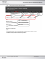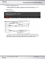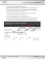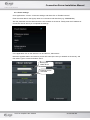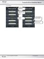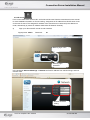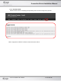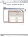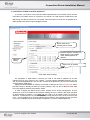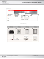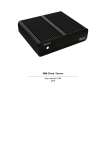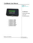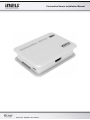
1
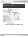
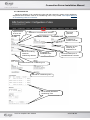
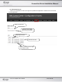
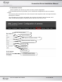
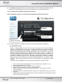
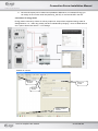
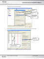
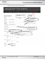
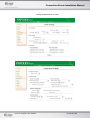
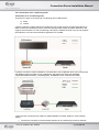
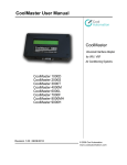
Connection Server Installation Manual Version 02‐ 039/2011 Rev.:091013 Connection Server Installation Manual Contents Contents .............................................................................................................................................................................. 2 1. Getting started ......................................................................................................................................................... 3 1.1. Putting Connection Server in run ................................................................................................................. 3 1.2. Basic settings................................................................................................................................................ 4 1.2.1. Change of password................................................................................................................................ 4 1.2.2. System restart and shutdown .................................................................................................................. 4 1.2.3. Setting static Connection Server IP address ........................................................................................... 5 2. Configuration in iMM Control Center..................................................................................................................... 6 2.1. iMM CC setting............................................................................................................................................ 6 2.1.1. Bookmark Server .................................................................................................................................... 6 2.1.2. Bookmark Configuration ........................................................................................................................ 6 2.1.3. Bookmark A/C ........................................................................................................................................ 8 2.1.4. Bookmark Rooms ................................................................................................................................... 9 2.1.5. Bookmark Cameras .............................................................................................................................. 10 2.1.6. Calling between individual devices and sound ..................................................................................... 11 2.1.7. Phone settings ....................................................................................................................................... 12 2.1.8. IP sound ............................................................................................................................................... 14 2.1.9. Bookmark Energy ................................................................................................................................. 15 2.1.10. Bookmark Audit .............................................................................................................................. 19 2.2. Heating ....................................................................................................................................................... 20 2.3. Connection of Miele household appliances................................................................................................ 21 3. Supplements .......................................................................................................................................................... 23 3.1. Export of configuration file to iMM........................................................................................................... 23 3.2. Third parties' devices ................................................................................................................................ 24 3.2.1. Supported Miele appliances.................................................................................................................. 24 3.2.2. Air conditioning unit CoolMaster ......................................................................................................... 26 3.2.3. Connection of air conditioning units .................................................................................................... 29 Verze 02‐ 039/2011 Rev.:091013 Stránka 2 z 31 Connection Server Installation Manual 1. Getting started Commands are given in purple, e.g.: sudo reboot Paths and links are given in red: imm/Pictures Notices are given in orange: No characters display when writing a password in terminal Tips and tricks are given in green: You do not want to run configuration via iMM CC at every server separately; as long as they are more, iMM CC can be enabled from any PC connected to local network… Commands are in italic Important configuration commands in Linux: Ifconfig - finding IP address of station/server, similar to IPCONFIG in Windows mount – command for connection of certain device CD-ROM, network drive, etc.) umount - command for disconnection of certain device 1.1. Putting Connection Server in run a) Once you unpack Connection server, let the device stabilize at room temperature. b) Insert attached SD card in the slot. c) Connect the cabling (do not connect the supply yet): Display HDMI device LAN cable for ethernet port! Keyboard to USB port. d) After connecting the power supply (adapter with micro USB connector), Connection Server will start automatically. e) When starting the system you can watch opening of individual services on the screen. Some services do not open, and display FAILD in red; in majority of cases it is not a problem; and has no influence whatsoever on the run of Connection Server. f) When start of services is completed, only one line requiring login name will appear on the screen. Alarmpi login: imm Password: imm123 No characters display when writing a password in terminal Verze 02‐ 039/2011 Rev.:091013 Stránka 3 z 31 Connection Server Installation Manual g) To find IP address after signup use command ifconfig h) Further settings are performed via web interface iMM Control Center. And display device or keyboard need not be connected for the rest of time. Power supply, SD card with system and application and connection to network is sufficient to run Connection Server. 1.2. Basic settings Setting in this chapter need not be carried out; it serves for potential problem solution and general assistance in the Linux system orientation. Majority of these settings is done already in the production but one should get familiarized with them and go back to them if a problem occurs. 1.2.1. Change of password a) Enter sudo passwd and confirm by Enter. b) You will be asked to enter the original password (default is “imm123“), and confirm by Enter. c) Then enter a new password, confirm by Enter; repeat the new password and confirm by Enter. No characters display when writing a password in terminal. 1.2.2. System restart and shutdown If you already know the IP address of Connection Server, the best way to restart or switch off is via iMMCC or remote access. By means of SSH e.g. in Putty software (free downloadable on internet). Sign up with the same data: Login: imm Password: imm123 Command for restart: sudo reboot Command for switching off: sudo shutdown If you begin with sudo command, Linux should always ask to enter the password. Verze 02‐ 039/2011 Rev.:091013 Stránka 4 z 31 Connection Server Installation Manual 1.2.3. Setting static Connection Server IP address IP address in sub-network which iMM server is connected to Mask setting Default gate a DNS server Network interface setting Button for complete shutdown Restart button In the System bookmark, you can reset parameters of network setting or restart, or use the “Shutdown” button to turn off Connection Server completely. IP address is usually set static to avoid its change in time. Verze 02‐ 039/2011 Rev.:091013 Stránka 5 z 31 Connection Server Installation Manual 2. Configuration in iMM Control Center IMM Control Center (the “iMMCC” hereinafter) is web interface serving for Connection Server setting. iMM CC is activated upon entering an address in your internet browser. 2.1. iMM CC setting 2.1.1.Bookmark Server Virtual server communicating with central unit Virtual server communicating with Miele Virtual server communicating with iHC applications This bookmark contains control to virtual servers necessary for communication with CU, applications and devices of third parties. Within diagnostics, the state of individual virtual servers can be revealed (button “Status”), suspend their run (button "Stop"), or turn them on (button "Start"). Servers are turned on automatically when Connection Server starts up. Verze 02‐ 039/2011 Rev.:091013 Stránka 6 z 31 Connection Server Installation Manual 2.1.2.Bookmark Configuration Central unit IP address iMM server IP address Application licence Update settings Find file “export.pub“ Upload file “export.pub“ There are units, events and variables from iNELS that are imported to iMM Save changes performed in the extract from file export.pub On this bookmark you can set IP address of central unit, IP address of server; in this case local address of Connection Server by entering 127.0.0.1! There you can also upload export.pub exported from central unit Verze 02‐ 039/2011 Rev.:091013 Stránka 7 z 31 Connection Server Installation Manual 2.1.3.Bookmark A/C Serves for definition of air conditioning units and their control by means of iHC application. Supported communication card for air conditioning units is LG je PI485. See chapter Wiring of Air Conditioning Units for connection. Optional name of inner unit Selection of communication interface Unit name (optional) IP address of RS232 converter Selection of UID same as you selected for air Serves for entering central air conditioning address IP address of RS485/Ethernet t t Communication port of RS485/Ethernet converter Creates defined air conditioning unit Central air conditioning unit List of already defined air Seznam již definovaných conditioning units klimatizačních jednotek Verze 02‐ 039/2011 Rev.:091013 Stránka 8 z 31 Connection Server Installation Manual 2.1.4.Bookmark Rooms Serves for configuration of file rooms.cfg which uploads iHC applications. Read more in the manual for iHC application. Name of new room Control of room will be protected by password Editing items in room Removal of room Password setting and change for access to room Verze 02‐ 039/2011 Rev.:091013 Stránka 9 z 31 Connection Server Installation Manual 2.1.5.Bookmark Cameras Serves for defining IP cameras you want to check by means of Application. HTTP and RTSP ports are only entered if your IP cameras are configured for access from external network. All cameras by Axis manufacturer with V2 and V3 protocol are supported, further we support the below listed types of cameras: AirLive-WL2600, AirLive AirCam OD-600HD, AirLive AirCam OD-325HD, Planet ICA-M220, ACTiACM, and the following types by company Vivotek: FD-8134, FD-7132, PZ-7132. Select any camera name Camera IP address User name for access to camera Access password for camera HTTP port RTSP port Camera type List of already defined cameras Verze 02‐ 039/2011 Rev.:091013 Stránka 10 z 31 Connection Server Installation Manual 2.1.6.Calling between individual devices and sound Set the following in the bookmark Intercoms: name, SIP name, password and videostream of device that you select beforehand for the device to call (sound, iMM client, phone), and add using the Add key. Copy Videostream from individual devices as long as they support it, e.g.: sounds from web interface, webcamera or any IP camera. For instance, for 2n sound it will be stream, e.g.: “rtsp://192.168.88.83“ which consists of “„ rtsp:// „ which is a kind of stream and sound IP address. Once you set all calling devices, save it by pressing Apply settings. Note: After clicking the Apply settings option, configuration files of asterisk server will overwrite. If you need own asterisk configuration, do not use "Apply settings", and modify configuration files manually. Add new contacts in iMMCC by filling in the contact and clicking the Add key. Entering SIP name Passwor d Video Stream Device name (optional) Verze 02‐ 039/2011 Rev.:091013 Stránka 11 z 31 Connection Server Installation Manual 2.1.7.Phone settings Go to applications menu intercom settings, and there click on "Enable intercom" Enter the same data for the signup name as on the server web interface (e.g. SAMSUNGS3) Also the password must be identical with the one entered on the server. Finally enter the IP address of Connection Server where you completed the settings. In the application click on the intercom icon and then on „Add contact“. Name the opposite station and enter its precise SIP name (the name you entered on the server), and then select Type of contact and select “Save”. Naming the called device Entering precise SIP name Verze 02‐ 039/2011 Rev.:091013 Stránka 12 z 31 Connection Server Installation Manual Sound settings: Naming the sound in the h SIP name same as the one on the server Sound IP address Login name web sound interface Password for web sound interface Verze 02‐ 039/2011 Rev.:091013 Stránka 13 z 31 Connection Server Installation Manual 2.1.8.IP sound For IP sound 2N® Helios a source DC 12V/2A should be used. See the manufacturer's user manual for more detailed information on IP sound wiring. Assignment of IP address from DHCP server is set on the new IP sound. The assigned IP address of the sound has to be ensured (in the abstract on router, alternatively by means of software 2N® Helios IP Network Scanner) a) Sign up to discovered IP sound via web interface. Signup name: admin Password: 2n Entering login name Entering login password In the bookmark AdvancedSettings -> Network set fixed IP address from relevant range, and subnetwork mask. Network interface setting Verze 02‐ 039/2011 Rev.:091013 Stránka 14 z 31 Connection Server Installation Manual b) The config.ini file generated from server web interface of a line where the added IP sound is located, has to be uploaded to IP sound via its web interface, in the following bookmark: Tools ->Configuration->Uploadconfigurationfile to device Before uploading config.ini to sound, the Network Settings field must be ticked off. Finding file config.ini Has to be ticked off before Upload Confirmation of selection and Upload For successful completion of installation the device must be restarted after the installation. 2.1.9.Bookmark Energy Directly in iMM Application the amount of energy consumption can be clearly displayed. Energy is recounted based on the amount of impulses that provide outputs from meters (gas-meters, electrometers, water-meters). Impulses are further processed in an optional input unit of system iNELS (IM2-140M, IM2-20/40/80B) in form of a counter. This value is by means of export.pub transferred to Connection Server where variable is in iMMCC on bookmark Energy assigned to Watter/Gas/Electrical. The setting of pulse conversion to unit of measure, selection of currency and setting the currency/unit is performed in iMMCC application in activated Energy module. The Energy module allows recording of consumed energy for a day, week, month and year. Data are saved in iMM Server – the data do not get lost even in case of power shutdown or power cut. Consumption can be displayed in a table or graph. Consumed energy is displayed not only in given quantity but also as financial value. 1. 2. 3. 4. 5. Click on the System Configuration button (icon of hammer and screwdriver – F11) Select bookmark System -> counters Add counter that you name by energy you want to measure Create a new action that you name e.g. upload electricity Add a command in the action which will be user action -> commands for counters -> increment counter 6. Select counter that corresponds with given action (e.g. for upload electricity you put counter electricity) 7. Add the action created as described above in system configuration to relevant binary input in action line when the input closes Verze 02‐ 039/2011 Rev.:091013 Stránka 15 z 31 Connection Server Installation Manual 8. Once the file export-pub is created and uploaded to iMM server, in bookmark Energy you can assign in the counter value line (electricity_VALUE). It must be VALUE in the line. Connection of energy meter Energy meter connects by means of a binary output unit. Output from supported energy meter is distinguished to + a -, that’s why polarity has to be maintained by bringing – minus to GND terminal and + plus to IN terminal. See 3.1.7. for settings. Creation of counter: Bookmark Counters Naming of counter Bookmark System Addition of further counters Verze 02‐ 039/2011 Rev.:091013 Stránka 16 z 31 Connection Server Installation Manual Creation of action “Counter incrementing": User action selection Select Increment counter Select uploading of required energy counter Action assignment to binary input where output from measuring instrument is connected. Add action Energy upload Input of binary input unit where output from measuring instrument is connected Verze 02‐ 039/2011 Rev.:091013 Stránka 17 z 31 Connection Server Installation Manual Assignment of counter value in iMM Control Center For hot water consumption measurement For cold water consumption measurement For gas consumption measurement Selection of counters from file export.pub For electricity consumption measurement (for up to 5 independent measurements Switching of basic unit Number of impulses for given unit Price of one impulse Currency setting Verze 02‐ 039/2011 Rev.:091013 Stránka 18 z 31 Connection Server Installation Manual 2.1.10. Bookmark Audit Bookmark Audit serves for displaying and uploading LOG of events for diagnostic purposes. When configuration in iMM CC is finished, restart Connection Server. Verze 02‐ 039/2011 Rev.:091013 Stránka 19 z 31 Connection Server Installation Manual 2.2. Heating Iin iHC application you can switch between individual heating modes within given temperature program (Minimum, Inhibition, Normal, Comfort, Auto). If you wish to control individual heating modes, you have to enable export of control and setting of heating program in IDM software. In time/weekly program administrator a part of export setting for visualisation. Enabling export of heating circuits for visualisation Verze 02‐ 039/2011 Rev.:091013 Stránka 20 z 31 Connection Server Installation Manual 2.3. Connection of Miele household appliances To connect, you need to have connected Gate-wayXGW 2000 in the network which receives information from Miele device on PowerLine, and sends it on LAN network to iMM server and iMM clients. All devices must be on one phase. Communication on power line is enabled by all Miele appliances that have logo miele@Connection. Name under which Gateway will be visible Network settings: IP address of Miele gateway, sub-network mask, default gateway IP address Network setting DNS server IP address XGW 2000 network setting For integration of XGW 2000 in network you need to set fixed IP address via its web interface from te given range of your network. On web interface Miele@Connection you can see all connected appliances. You can thus check that all appliances you use have sufficiently strong signal for XGW 2000. Setting the MieleGateWay IP address is recorded on iMM server in file /etc/imm/miele where the basic shape is already set within the factory settings, and only the IP address XGW 2000 has to be added in between the quotation marks. In order to display the Miele control screen, similarly as for energy management, an icon referring to it has to be added on the Floorplan. Adding the icon is ruled by the same principles as those advised in chapter 4.1 provided that you need to go for "Miele" option on the list of elements. To describe the icon it is NECESSARY to keep the same name as is the name of the room – for the appliance on the web interface (Room Name). Only appliances with the same room name sill display which serves better arrangement in Control of Miele appliances. Verze 02‐ 039/2011 Rev.:091013 Stránka 21 z 31 Connection Server Installation Manual Naming of appliances Room name Basic Miele wiring Verze 02‐ 039/2011 Rev.:091013 Stránka 22 z 31 Connection Server Installation Manual 3. Supplements 3.1. Export of configuration file to iMM In the iNELS Design Manager (iDM) environment in the window “General Settings” select by the picture. Export will be performed when the project is saved in the central unit! Two files Export.exp and Export.pub will be created in selected folder; the Export.pub is important for upload in iMM Control Centre. In case of large installation we recommend to use cutchoose program for export.pub. This program serves for trimming export pub only for useful and important elements, and thus easier searching of elements in iMM floorplan in configuration. If subtitles do not display correctly, subtitle encoding must be changed. The UNICODE encoding is set in the default. Verze 02‐ 039/2011 Rev.:091013 Stránka 23 z 31 Connection Server Installation Manual 3.2. Third parties' devices 3.2.1.Supported Miele appliances Washing machines W 5967 WPS AutoDos W 5000 WPS Supertronic W 2859i WPM Integrated steam ovens DG 5080 DGC 5080 XL DGC 5085 XL Glass ceramic cooking hotplates KM 6202 KM 6204 KM 6212 Driers T 4859 Ci T 8969 WP EcoComfort T 8001 WP Supertronic Dishwashers G 5930 SCi G 5935 SCi XXL G 5980 SCVi G 5985 SCVi XXL Coffee makers CVA 5060 CVA 5065 Verze 02‐ 039/2011 Rev.:091013 Stránka 24 z 31 Connection Server Installation Manual Integrated baking ovens H 5681 B H 5681 BP H 5681 BL/R H 5681 BPL/R H 5981 BP H 5081 B H 5081 BP H 5080 B Induction cooktops KM 5956 KM 6314 KM 6315 KM 6317 KM 6346 KM 6352 KM 6354 KM 6380 KM 6382 KM 6383 Kitchen aspirators DA 420-4 DA 420 V DA 424 V DA 430-4 DA 5000 D DA 5100 D DA 5294 D DA 5320 D DA 5330 D DA 5590 D DA 5620 D DA 6290 D DA 6590 D DA 6520 D DA 249-4 DA 289-4 DA 439 DA 489-4 DA 5190 W DA 5294 W DA 5320 W DA 5390 W DA 5590 W DA 5690 W DA 6000W DA 6290 W DA 6590 W Verze 02‐ 039/2011 Rev.:091013 Stránka 25 z 31 Connection Server Installation Manual 3.2.2.Air conditioning unit CoolMaster CoolMaster There are 8 different versions for individual air conditioning makers • CoolMaster Daikin 1000D • CoolMaster Sanyo 2000S • CoolMaster Toshiba3000T • CoolMaster Mitsubishi Electric 4000M • CoolMaster LG 6000L • CoolMaster Fujitsu 7000F • CoolMaster Mitsubishi Heavy 8000MH • CoolMaster Hitachi 9000H Step-by-step putting in operation: 1. Connect all by the attached wiring scheme 2. Set the RS232/ETHERNET converter 3. Set the central address on the wall air conditioning unit control 4. iMM communicates via converter Papouch GNOME RS232 and its IP address has to be entered in file /etc/imm/coolMaster.cfg together with the type of the CoolMaster control unit. If everything is set correctly, the CoolMaster display will not show U00 G00 but the typed address. For instance, U00 G01. Then everything goes via iMM client but the air conditioning unit can still be controlled via local control; they mutually synchronize. Illustrative putting in operation: Wiring scheme Connectors on unit Verze 02‐ 039/2011 Rev.:091013 Stránka 26 z 31 Connection Server Installation Manual Setting the RS232/ETH converter Verze 02‐ 039/2011 Rev.:091013 Stránka 27 z 31 Connection Server Installation Manual How to set Daikin central address Press and hold down for 5 seconds the TEST button Setting mode 00 shows in the middle, and GROUP and the number on the left. (GROUP should flash; if not press the Select the desired central address using the on/off key; then it should flash). time setting button Confirm by pressing the on/off button. Complete settings by TEST button. Verze 02‐ 039/2011 Rev.:091013 Stránka 28 z 31 Connection Server Installation Manual 3.2.3.Connection of air conditioning units Connection of air conditioning units There are two ways of connecting air conditioning units in iMM system: a) Direct b) Indirect a) Direct connection means that the air conditioning unit control protocol is implemented directly in iMM. Currently air conditioning units of LG brand are supported; others have been worked on. We support communication of LG air conditioning units which is marked as PI485. Any LG unit supports that interface; it can be interconnected to application iTP via iMM. b) Indirect connection means utilization of communication unit CoolMaster which can communicate with different types and makers of air conditioning units (http://www.inels.cz/media/PDFexport/download/Coolmaster_compatibility.pdf). CoolMaster is then controlled from iMM. Interconnection is performed by means of 485/ETHERNET converter. Steps for communication setting: 1. Connect the converter to communication interface of air conditioning unit and to ethernet. Verze 02‐ 039/2011 Rev.:091013 Stránka 29 z 31 Connection Server Installation Manual 2. Set central address on air conditioning unit using a remote control (see the air conditioning unit user manual). Example: RESET – hold down MODE – hold down Release RESET When 00 displays, release MODE Set the address inside the unit using buttons for temperature setting Press ON/OFF for directing to the inner unit Address displays on the unit To finish the setting, reset the control To check the address: RESET + PLASMA 3. Set the converter 4. Add the air conditioning unit in clims in iMM web interface (see 2.1.4.) 5. Add air conditioning units in rooms in iMM web interface (see 2.1.5.) 2.1.5.) Setting the 485/ethernet converter – bookmark Serial Settings Setting the 485/ethernet converter – bookmark Connection Verze 02‐ 039/2011 Rev.:091013 Stránka 30 z 31 Connection Server Installation Manual Verze 02‐ 039/2011 Rev.:091013 Stránka 31 z 31