1
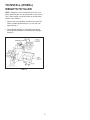
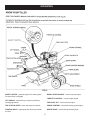
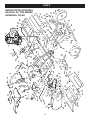
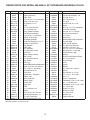
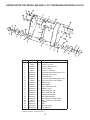
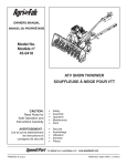
Owner's Manual
®
STOP
36" TOW-BEHIND
UNIVERSAL TILLER
Model No. 486.252444
CAUTION:
Before using this product, read
this manual and follow all Safety
Rules and Operating Instructions.
DO NOT RETURN TO STORE
For Missing Parts or Assembly
Questions Call 1-866-576-8388
• Safety
• Assembly
• Operation
• Maintenance
• Parts
Sears, Roebuck and Co., Hoffman Estates, IL 60179 U.S.A.
www.sears.com/craftsman
PRINTED IN U.S.A.
FORM NO. 49940 (04/24/08)
TABLE OF CONTENTS
SERVICE AND ADJUSTMENT...................................... 11
STORAGE...................................................................... 12
TROUBLESHOOTING.................................................... 13
REPAIR PARTS.............................................................. 14
PARTS ORDERING/SERVICE......................... Rear Cover
WARRANTY..................................................................... 2
SAFETY RULES............................................................... 3
ASSEMBLY....................................................................... 4
OPERATION..................................................................... 6
MAINTENANCE............................................................... 9
LIMITED WARRANTY ON CRAFTSMAN POWERED TRACTOR ATTACHMENTS
For one (1) year from the date of purchase, if this Craftsman Equipment is maintained, lubricated and tuned
up according to the instructions in the owner's manual, Sears will repair or replace free of charge any parts
found to be defective in material or workmanship. Warranty service is available free of charge by returning
your Craftsman equipment to your nearest Sears Service Center. In-home warranty service is available but a
trip charge will apply. This Warranty applies only while this product is in the United States.
This Warranty does not cover:
• Expendable items which become worn during normal use, such as spark plugs, air cleaners, belts, and oil
filters.
• Tire replacement or repair caused by punctures from outside objects, such as nails, thorns, stumps, or
glass.
• Repairs necessary because of operator abuse, including but not limited to, damage caused by impacting
objects that bend the frame or crankshaft, or over-speeding the engine.
• Repairs necessary because of operator negligence, including but not limited to, electrical and mechanical
damage caused by improper storage, failure to use the proper grade and amount of engine oil, or failure to
maintain the equipment according to the instructions contained in the owner's manual.
• Engine (fuel system) cleaning or repairs caused by fuel determined to be contaminated or oxidized (stale).
In general, fuel should be used within 30 days of its purchase date.
• Equipment used for commercial or rental purposes.
LIMITED WARRANTY ON BATTERY
For ninety (90) days from date of purchase, if any battery included with the equipment proves defective in
material or workmanship and our testing determines the battery will not hold a charge, Sears will replace the
battery at no charge. Warranty service is available free of charge by returning your Craftsman equipment to
your nearest Sears Service Center. In-home warranty service is available but a trip charge will apply. This
Warranty applies only while this product is in the United States.
TO LOCATE THE NEAREST SEARS SERVICE CENTER OR TO SCHEDULE SERVICE,
SIMPLY CONTACT SEARS AT 1-800-4-MY-HOME.
This warranty gives you specific legal rights, and you may also have other rights, which vary from state to
state.
PRODUCT SPECIFICATIONS
Record serial number and date of purchase in space
provided below.
GASOLINE TYPE
OIL TYPE
(API-SF/SG)
OIL CAPACITY:
SPARK PLUG
TILLING GROUND SPEED
TILLING WIDTH
TILLING TINE SPEED
MODEL
486.252444
NUMBER: ______________________________
SERIAL
NUMBER: ______________________________
DATE OF
PURCHASE: ____________________________
The model and serial numbers will be found on a
plate attached to the right hand chassis.
You should record both serial number and date of
purchase and keep in a safe place for future
reference.
2
REGULAR UNLEADED
SAE 30 (ABOVE 32° F)
SAE 5W-30 (BELOW 32° F)
20 OZ.
(GAP .030")
Approx. 2 MPH
36 INCHES
200 RPM
SAFETY
WARNING: This cutting machine is capable of amputating hands and feet and throwing objects. Failure to
observe the following safety instructions could result in serious injury or death.
IMPORTANT
•
Warnings, Cautions, and Notes are a means of attracting
attention to important or critical information in this
manual.
•
Look for this symbol to point out important
safety precautions. It means-Attention!
Become Alert! Your safety is involved.
•
•
TRAINING
•
•
•
•
Read opening and Service instructions carefully. Be
thoroughly familiar with the controls and the proper
use of the equipment.
Never allow children to operate the machine. Do not
allow adults to operate the machine without proper
instruction.
Keep the area of operation clear of all persons,
particularly small children and pets.
•
•
•
Stop engine and disconnect spark plug lead wire
before cleaning augers, removing obstacles, or
making adjustments, except for those which must
be done with the engine running.
Never place hands or feet under or into rotating
parts or concealed areas. Keep hands and feet
clearly away from auger elements, belts, pulleys,
etc. while engine is running.
Wear substantial shoes and eye protection while
using tiller.
Never attempt to make a maintenance adjustment
while engine is running, except on the carburetor.
Do not run the engine indoors; carbon monoxide
fumes are dangerous to inhale.
Never operate machine without proper guards,
plates, or other safety protective devices in place.
Disengage the Tine Clutch Lever, stop tiller and
tractor engines before getting off the tractor.
Disengage the Tine Clutch Lever and stop the tiller
engine during transportation to and from the work
area.
PREPARATION
MAINTENANCE AND STORAGE
•
•
•
•
Check the fuel and lubrication before starting the
engine. Do not fill the gasoline tank indoors when
the engine is running or while the engine is still hot.
Wipe off any spilled gasoline before starting the
engine.
Inspect the area to be tilled. Remove glass, wire,
metal objects, large sticks, and stones. Avoid
underground pipes and wiring. Have a complete working knowledge of your tractor
and know how to handle your tractor with a tiller or
other attachment attached.
•
•
•
OPERATION
•
•
•
•
•
Follow maintenance instructions as outlined in this
manual and your Engine Owner's Manual supplied
with the unit.
Disconnect spark plug wire before making
maintenance adjustment or repair.
Store gasoline in an approved metal container in a
cool, dry place.
Safety and performance levels can be assured only
by the use of specified replacement parts.
WARNING: This unit is equipped with an
internal combustion engine and should
not be used on or near any unimproved
forest-covered or grass-covered land
unless the engine's exhaust system is equipped with a
spark arrester meeting applicable local or state laws
(if any). If a spark arrester is used, it should be
maintained in effective working order by the operator.
In the state of California, the above law is required by
law (Section 4442 of the California Public Resources
Code). Other states may have similar laws. Federal
laws apply on Federal lands. A spark arrester for the
muffler is available through your nearest Sears
Authorized Service Center.
Give complete and undivided attention to the job at
hand. Operate the tiller in daylight or good artificial
light.
Personal injury may result from contact with the
augers or debris thrown by this machine. Therefore,
always stay a safe distance away from the augers.
Stop the tiller engine when leaving your tiller
unattended.
Check before each use for loose fasteners or parts.
Never store the equipment with gasoline in the tank
inside of a building where fumes may reach an open
flame or spark. Allow engine to cool before storing in
an enclosure.
3
ASSEMBLY
TO REMOVE UNIT FROM
CARTON
TO INSTALL THE TILLER
GAUGE WHEELS
• Cut from top to bottom all four corners of the carton
and lay panels flat. (See Fig. 1)
• Remove the lag screw that holds the floating hitch to
the packing skid.
• Disassemble and discard carton's wood top and side
supports.
• Remove four hex bolt, hex nuts and flat washer from
the hold down brackets at the rear of the carton.
• Remove and save the two Flat Washers and Cotter
Pins from the rear axle. Reuse when attaching gauge
wheels.
• Discard all other packing hardware and hold down
brackets.
• Assemble Gauge Wheels onto the Rear Axle with the
extended end of Hub facing inward. Secure with the
Flat Washers and Cotter Pins which you removed from
the axle during unpacking. (See fig. 2.)
FIG. 2
TO INSTALL THE TILLER TINE
ASSEMBLIES
• Attach the floating hitch to the tractor's draw bar.
(Refer to Operating Instructions on page 7.)
• Remove the preassembled 3/8" x 2" hex bolt and 3/8"
nylock nut from the L.H. Tine Assembly. Slide the tine
assembly onto the Transmission Axle on the left side
of the tiller and secure with the hex bolt and nylock
nut. (See fig. 3.) Repeat for the R.H. side.
FIG. 1
3/8" NYLOCK
NUT
• Right hand (RH) and left hand (LH) are determined
from the drivers position while seated on the tractor.
• We recommend that you remove the Mower Deck
before using the Tiller. Refer to your Tractor Owner's
Manual.
FIG. 3
4
TO INSTALL (WHEEL)
WEIGHTS TO TILLER
NOTE: Weights are not furnished with the Tiller. 30 lb.
tractor wheel weights may be purchased to mount to the
Tiller if extra weight is required. (Refer to the Operation
section of this manual.)
• Remove two Carriage Bolts and Nuts from each Tine
Shield, located approximately 3-1/2" from the front
edge. See fig. 4.
• Place (Wheel) Weights on Tine Shield and secure
with long Bolts and Nuts furnished with the Weights.
See fig. 4.
FIG. 4
5
OPERATION
FIG. 5
SAFETY SWITCH - prevents engine from starting while
tine clutch lever is engaged
RECOIL START HANDLE - used to start the engine
THROTTLE CONTROL - controls engine speed
LIFT HANDLE - selects tilling or transport position by
moving gage wheels
FUEL SHUT OFF - shuts of fuel to engine
TINE CLUTCH LEVER - starts and stops tine rotation
CHOKE CONTROL - used when starting a cold engine
FLOATING HITCH - telescoping hitch limits shock loads
to tractor
DEPTH STAKE - controls tilling/cultivating depth
6
The operation of any tiller can result in foreign objects thrown into the eyes, which can
result in severe eye damage. Always wear safety glasses or eye shields before starting
your tiller and while tilling. We recommend a wide vision safety mask for over the
spectacles or standard safety glasses.
HOW TO USE YOUR TILLER
•
BEFORE STARTING YOUR TILLER
•
FILL THE ENGINE WITH OIL! Your tiller engine is
shipped without oil or gasoline. Add oil and gas as
instructed in the separate engine manual.
Repeat instructions in two preceding paragraphs until
engine fires. When engine starts, move choke control
gradually to RUN position.
Allow engine to warm up for a few minutes before
engaging tines.
ATTACHING TILLER TO TRACTOR
(See Fig. 6)
WARNING: Never fill fuel tank indoors, or
with the engine running, or while the engine
is hot. Do not smoke while filling tank.
•
•
•
STOPPING YOUR TILLER
•
TINES
• Raise tiller to transport position.
• Pull forward on tine clutch lever.
Rear wheel weights and tire chains can be used on
tractor if additional traction is required for tilling.
Place Tiller on ground level and back up tractor to it.
Slide Floating Hitch of Tiller onto the tractor drawbar
so that the hitch pin holes line up.
Insert hitch pin until it extends through bottom of
Floating Hitch. Insert hair cotter pin into hitch pin.
ENGINE (Refer to separate engine manual.)
• Move throttle control to "STOP" position.
• Turn shut off to "OFF" position.
• Never use choke to stop engine.
STARTING YOUR TILLER
(Refer to separate engine manual.)
CAUTION: The muffler and adjacent
areas are hot!
•
•
•
•
•
•
•
•
Check oil and gas in Tiller engine.
Attach spark plug wire to spark plug.
Pull forward on tine clutch lever to disengage tines.
A safety switch prevents engine from starting while
tines are engaged.
Turn shut off to "ON" position.
Move choke lever on engine to CHOKE position.
(A warm engine may not require choking.)
Move throttle control lever on engine to FAST
position.
Grasp starter handle and pull rope out slowly until
engine reaches start of compression cycle (rope will
pull slightly harder at this point). Let the rope rewind
slowly.
Pull rope with a rapid, continuous, full arm stroke.
Keep a firm grip on starter handle. Let rope rewind
slowly. Do not let starter handle snap back against
starter.
FIG. 6
BREAKING IN YOUR TILLER
Break-in your belts, pulleys and the control before you
actually begin tilling.
• Start engine with tiller attached to tractor in transport
position. Engage Tine Clutch Lever to start tine
rotation. Allow tines to rotate for five minutes.
• Check tine operation and adjust if necessary. See
"TINE OPERATION CHECK" in the Service and
Adjustments section of this manual.
7
TRANSPORTING YOUR TILLER
AROUND THE YARD
• Pull forward on lift handle until it locks in the up,
transport position.
AROUND TOWN
• Disconnect spark plug wire.
• Drain fuel tank.
• Transport in upright position to prevent oil leakage.
8
MAINTENANCE
MAINTENANCE SCHEDULE
Fill in dates as you
complete regular service.
Check Engine Oil Level
Be
fore
eac
hu
se
Firs
t5
to 8
hrs
25
.
eve hrs.
ry s or
eas
50
on
h
eve rs.
ry s or
eas
on
1
ev0e0 hrs
ry s . or
eas
on
Yea
rly
Refer to the engine manual for instructions on engine maintenance.
X
Change Engine Oil
X
X*
Service air cleaner precleaner
X**
Service air cleaner cartridge
X**
Replace spark plug
X
Clean cooling system
X**
Check valve clearance
Check for loose fasteners
Service Dates
X
X
Lubricate Tiller
X
Lubricate Tiller Transmission
X
*Change oil every 25 hours when operating the engine under heavy load or in high temperatures.
**Clean more often under dusty conditions or when airborne debris is present. Replace air cleaner parts, if very dirty.
9
TILLER LUBRICATION
Check transmission oil level after first 5 hours of
operation. Remove Oil Fill Plug (Fig. 10). Oil Level must
be even with the Plug Hole (with Tiller level.) If necessary,
add Oil. Use SAE30 Non-Detergent Motor Oil. Replace
Oil Fill Plug.
Check transmission oil level after each 10 hours of
operation.
NOTE: It is not necessary to change the Oil in the Tiller
Transmission. If for any reason it must be changed, Oil
capacity is 22 oz.
ENGINE MAINTENANCE
WARNING: Always stop engine and
disconnect spark plug wire before cleaning,
lubricating or before performing any repairs
or maintenance.
•
•
•
•
Check oil level before each use and every 8 hours.
Maintain engine oil as instructed in the separate
engine manual.
Service air cleaner every 25 hours under normal
conditions. Clean every few hours under extremely
dusty conditions. Poor engine performance and
flooding usually indicates that the air cleaner should
be serviced. To service the air cleaner, refer to the
separate engine manual.
Spark plug replacement is recommended every 100
hours or yearly. Check the engine manual for correct
plug type and gap specifications.
10
SERVICE AND ADJUSTMENTS
WARNING: Shut off (disengage) the Tine
Clutch Lever, the Tiller Engine and the Tractor
Engine before making any repairs.
TO REPLACE V-BELT
Replace V-belt if it has been damaged considerably from
slipping under heavy loads or if it show cracks or frayed
edges. Refer to figures 11 and 12.
IMPORTANT: Do not move or remove the belt guide.
If the position of the belt guide is accidentally altered,
return it to the correct setting (6-1/2" above the tine shield
support plate).
•
•
•
•
•
Remove the screw from the top of the belt guard.
Remove the hex nut from the rear of the guard.
Remove the belt guard to allow access to drive belt.
Disengage tine clutch lever and remove belt.
Reverse above procedures for installation of new belt.
FIG. 12
FIG. 11
11
SPARE TINE DRIVE BOLTS
WARNING: Shut off (disengage) the Tine
Clutch Lever, the Tiller Engine and the Tractor
Engine before making any repairs.
•
The Tiller drive components are protected from
damage by (shearable) Grade 5 hex bolts in the
Tine Assemblies. The hex bolts drive the tines and
hold them in the proper location. Should the Tine
Assemblies strike or pick up a large hidden object
or become jammed, the hex bolts will break and the
drive components will not be damaged.
•
Two extra tine hex bolts and nuts are included with
the tiller. They are located in the Tiller Stake Support
Bracket on the rear of the Tiller.
•
The tine hex bolts are designed to be loose fit. Do not
attempt to use a bolt or pin that is larger or harder
than the original Grade 5 hex bolts.
TINE CARE
•
For best results--Tine Blades should be kept
reasonably sharp. The Tine Blade can be sharpened
on a grinding wheel. Do not attempt to sharpen Tines
while they are mounted to Tiller.
STORAGE
Immediately prepare your tiller for storage at the end of
the season or if the unit will not be used for 30 days or
more.
•
•
CAUTION: Never store the tiller with
gasoline in the tank inside a building,
where fumes may reach an open flame
or spark. Allow the engine to cool before
storing in any enclosure.
•
•
•
ENGINE
•
Follow the instructions in the "Service & Storage"
section of the Engine Manual.
WARNING: Never cover Tiller while
engine and exhaust areas are still warm.
TILLER
•
•
Lubricate as instructed in the Customer
Responsibilities section of this manual.
Be sure that all nuts, bolts and screws are securely
fastened. Inspect moving parts for damage, breakage
and wear. Replace if necessary.
Touch up all rusted or chipped paint surfaces; sand
lightly before painting.
If possible, store tiller indoors and cover it to protect
from dust and dirt.
Cover tiller with a suitable protective cover that does
not retain moisture. Do not use plastic. Plastic cannot
breathe, which allows condensation to form and will
cause your unit to rust.
Clean entire tiller (See "CLEANING" in the Customer
Responsibilities section of the manual).
Inspect and replace belts, if necessary (See belt
replacement instructions in the Service and Adjustments section of this manual.
12
TROUBLESHOOTING
Follow the instructions in the "Service & Storage" section of the
Engine Manual when performing any work on the Engine.
13
14
68
23
64
53
14
69
18
12
10
19
16
17
42
11
22
19 28
48
A
B
A
C
27
72
85
60
82
38
37
35
36
11
61 60
9
24
25
60
41
28
23
34
33
38
39
30
74
21
23
57
26
13
76
B
45
23
38
78
8
75
29
63
38
7
14
77
32
80
28
47
2
46
31
6
15
50
28
D
75
54
65 38
63
51
28
C
5 4 84
D
1
66
44
67
54
60
61
71
3
49
71
28
28
23
56
70
62
60
73
68
52
83
67
50
23
55
81
43
80
REPAIR PARTS FOR MODEL
486.25244 36" Tow-Behind
Universal Tiller
20
58
40
59
75
PARTS
REPAIR PARTS FOR MODEL 486.252444 36" Tow-Behind Universal Tiller
Ref.
1
2
3
4
5
6
7
8
9
10
11
12
13
14
15
16
17
18
19
20
21
22
23
24
25
26
27
28
29
30
31
32
33
34
35
36
37
38
39
40
41
42
43
Part No. Qty.
Description
Ref. Part No. Qty.
Description
40993
1 Engine (49 State)
44
HA20094
1 Tine & Hub Assembly - RH
40997
1 Engine (California)
45
HA20088
1 Tine & Hub Assembly - LH
48346
1 Guide - Belt
46
43054
4 Bolt, 3/8-16 x 2"
43085
4 Bolt, 5/16-18 x 1-1/2" Hex Head
47
47600
1 Bolt, Hex 5/16-24 x 1"
HA115321
1 Screw, 5/16-18 x 5/16"
48
HA5236
1 Pin, Hitch
HA11154
1 Key, Square 1/4" x 2"
49
43062
1 Hex Bolt, 3/8-16 x 1-1/2"
HA20176
1 Pulley
50
HA20918
2 Wheel
48733
1 Nut, 1/2-12 Nylock Jam
51 R74780828
1 Bolt, 1/2-13 x 1-3/4" Hex Head
HA124934
1 Nut, 1/2-12 Hex Jam
52
HA20670
1 Pivot Axle Assembly
HA19860
1 Spring, Depth Extension
53
43350
8 Bolt, 3/8-16 x 1" Carriage
64282
1 Hitch Bracket Assembly
54
HA20725
2 Strap Frame Extension
43063
5 Bolt, 5/16-18 x 1" Hex Head
55
HA3433
2 Pin, Clevis
43064
1 Locknut, 5/16-18 Hex
56
HA20690
1 Stake, Drag
64343
1 Lift Handle Assembly
57
HA20932
2 Wheel Weight Support Bracket
48840
3 Screw, Self-Tapping 1/4" x 1/2"
58
HA20940
1 Decal, Danger
43081
1 Washer, 5/16" Std. Wrt.
59
25830
1 Plate, Fender Support
HA20135
1 Ring, Retainer
60
47810
18 Nut, Hex 5/16-18 Nylock
HA20184
1 Pulley, Input
61
41576
5 Hex Bolt - 3/8-16 x 1-3/4"
HA20178
1 Bolt - Shoulder
62 R74760884
1 Bolt, 1/2-13 x 5-1/2" Hex Head
47189
6 Nut, Hex Nylock 1/4-20
63
44326
2 Bolt, 5/16-18 x 1" Carriage
24848
1 Clutch Rod
64
24849
1 Belt Guard (incl. #69)
HA23199
1 Switch, Safety Interlock
65
HA14306
1 Washer
24847
1 Lever, Clutch
66
HA20691
1 Strap-Frame Extension Brace
HA21362
19 Nut, Hex Nylock 3/8-16
67
712-3083
3 Nut, 1/2-13 Nylock
HA20170
1 Grip, Handle
68
HA20938
2 Decal, Danger
C-9M5732
2 Rivet, Pop
69
HA20942
1 Decal
HA20134
1 Bracket, Belt Guide & Idler Mounting 70
HA5713
1 Spacer
HA9131
4 Screw, 5/16-18 x 3/4" Self Tap
71
HA15200
2 Washer
43661
11 Bolt, 1/4-20 x 1" Hex Head
72
712-0261
1 Nut, Hex 5/18-11 Nylock
HA20185
1 Key, Woodruff No. 61
73
HA7974
2 Spacer
24863
1 Cover, Drive
74
48278
1 Bolt, Hex 5/8-11 x 7-1/2"
HA20119
1 Transmission - Complete
75
43010
6 Pin - 1/8" x 1-1/4" Cotter
24843
1 Chassis, Left
76
HA20688
1 Rod - Lift
HA20186
1 Spring, Extension
77
HA19649
1 Anchor - Adjustment
24844
1 Chassis, Right
78
HA120396
5 Flat Washer, 17/32" x 1-1/6" x .095"
24846
1 Bracket, Idler
79
HA124934
1 Nut - 1/2-20 Hex Jam
HA11496
1 Pulley, Idler
80
HA456151
4 Flat Washer, 13/16" x 1-1/2" x .134"
HA20187
1 V-Belt
81
HA20481
2 Pin - Hair Cotter
43013
7 Nut, 1/4-20 Hex Lock
82
HA22594
1 Shield, Tine (LH)
64284
1 Module
83
HA22595
1 Shield, Tine (RH)
43182
4 Bolt, 5/16-18 x 3/4" Hex Hd.
84
43178
1 Nut, Hex 1/4-20
HA20112
1 Rear Guard Assembly - LH
85 R19212113
1 Washer, 5/8"
714-0117
1 Pin - Hair Cotter 5/32"
49940
1 Owner's Manual
HA20113
1 Rear Guard Assembly - RH
*Standard Hardware - Purchase Locally
15
REPAIR PARTS FOR MODEL 486.252444 36" Tow-Behind Universal Tiller
Ref.
1
2
3
4
5
6
7
8
9
10
11
12
13
14
15
16
17
18
19
20
21
22
23
24
Part No.
HA20344
43064
HA20123
HA20122
43013
HA20120
HA20136
HA20127
HA20121
43866
HA20125
HA20124
HA20130
HA20129
HA20132
HA20128
HA20133
HA20131
HA20135
43012
HA20137
HA20145
HA20155
HA20138
Qty.
2
8
2
2
17
1
1
1
1
15
2
2
1
4
1
1
1
1
1
2
4
1
2
3
Description
Dust Cap
Locknut, 5/16-18 *
Flange & Bearing Assy
Gasket, Flange
Locknut, 1/4-20 Hex *
Drive Housing & Bearing Assy - LH
Gasket, Drive Housing
Tine Shaft Assy
Drive Housing & Bearing Assy - RH
Bolt, Hex 1/4-20 x 5/8" Grade 8
Washer, Felt
Seal, Rubber
Plug, Transmission Oil
Washer, Thrust
Chain Assembly #40
Chain Assembly #50
Input Shaft Assembly
Idler Shaft Assembly
Ring, Retainer 5/8" Dia. Shaft
Bolt - 1/4-20 x 3/4" Hex Head *
Bearing
Seal
Bearing, Flange
Cap, Bearing
*Standard Hardware - Purchased Locally
16
NOTES
17
NOTES
18
NOTES
19
Get it fixed, at your home or ours!
Your Home
For repair – in your home – of all major brand appliances,
lawn and garden equipment, or heating and cooling systems,
no matter who made it, no matter who sold it!
For the replacement parts, accessories and
owner’s manuals that you need to do-it-yourself.
For Sears professional installation of home appliances
and items like garage door openers and water heaters.
1-800-4-MY-HOME®
(1-800-469-4663)
Call anytime, day or night (U.S.A. and Canada)
www.sears.com
www.sears.ca
For expert home solutions advice: www.managemyhome.com
Our Home
For repair of carry-in items like vacuums, lawn equipment,
and electronics, call or go on-line for the location of your nearest
Sears Parts & Repair Service Center
1-800-488-1222 (U.S.A.)
1-800-469-4663 (Canada)
Call anytime, day or night
www.sears.com
www.sears.ca
To purchase a protection agreement on a product serviced by Sears:
1-800-827-6655 (U.S.A.)
1-800-361-6665 (Canada)
Para pedir servicio de reparación
a domicilio, y para ordenar piezas:
Au Canada pour service en français:
1-888-SU-HOGAR®
1-800-LE-FOYER MC
(1-888-784-6427)
® Registered Trademark / TM Trademark / SM Service Mark of Sears Brands, LLC
® Marca Registrada / TM Marca de Fábrica / SM Marca de Servicio de Sears Brands, LLC
MC
Marque de commerce / MD Marque déposée de Sears Brands, LLC
(1-800-533-6937)
www.sears.ca
© Sears Brands, LLC