1
!""#
$%&' (&)
!
DANGER
DANGER indicates an imminently hazardous situation that, if not avoided, will
result in death or serious injury.
DANGER is limited to the most extreme situations.
!
WARNING
WARNING indicates a potentially hazardous situation that, if not avoided, could
result in death or serious injury, and/or property damage.
!
CAUTION
CAUTION indicates a potentially hazardous situation that, if not avoided, could
result in minor or moderate injury, and/or damage to property.
CAUTION is also used for property-damage-only accidents.
Copyright 1995 by Siemens Energy & Automation, Inc.
All Rights Reserved — Printed in USA
Reproduction, transmission, or use of this document or contents is not permitted without express consent of
Siemens Energy & Automation, Inc. All rights, including rights created by patent grant or registration of a utility model or design, are
reserved.
Since Siemens Energy & Automation, Inc., does not possess full access to data concerning all of the uses and applications of
customer’s products, we do not assume responsibility either for customer product design or for any infringements of patents or rights
of others which may result from our assistance.
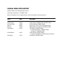
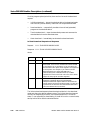
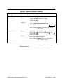
MANUAL PUBLICATION HISTORY
SIMATIC TIWAY I Series 500 NIM User Manual
Order Manual Number: PPX:TIWAY–8110
Refer to this history in all correspondence and/or discussion about this manual.
Event
Date
Description
Original Issue
Second Edition
Errata 1
Errata 2
Third Edition
02/84
04/86
06/86
07/86
02/87
Fourth Edition
10/87
Fifth Edition
11/95
Original Issue (2704516–0001; 2587872–0001)
Second Edition (2587872–0002)
Pages 5-13, 5-24, 5-28, 5-29 (2599154–0001)
History/Effective Pages, B-2 (2599154–0002)
Third Edition (2587872–0003)
Incorporates Errata 1 (2599154–0001)
and Errata 2 (2599154–0002)
Fourth Edition (2587872–0004)
Incorporates Release 3.0 NIM software updates
Fifth Edition (2587872–0005)
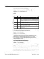
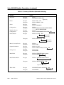
LIST OF EFFECTIVE PAGES
Pages
Cover/Copyright
History/Effective Pages
iii — x
1-1 — 1-7
2-1 — 2-16
3-1 — 3-18
4-1 — 4-64
A-1 — A-5
B-1 — B-6
C-1 — C-2
D-1 — D-2
E-1
F-1 — F-2
Registration
Description
Fifth
Fifth
Fifth
Fifth
Fifth
Fifth
Fifth
Fifth
Fifth
Fifth
Fifth
Fifth
Fifth
Fifth
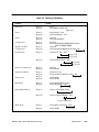
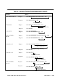
Pages
Description
Contents
Chapter 1
1.1
TIWAY I System Overview . . . . . . . . . . . . . . . . . . . . . . . . . . . . . . . . . . . . . . . . . . . . . . . . . . . . . . . .
1-2
TIWAY I Options . . . . . . . . . . . . . . . . . . . . . . . . . . . . . . . . . . . . . . . . . . . . . . . . . . . . . . . . . . . . . . . . .
System Block Diagram . . . . . . . . . . . . . . . . . . . . . . . . . . . . . . . . . . . . . . . . . . . . . . . . . . . . . . . . . .
TIWAY I Universal Command Language, UCL . . . . . . . . . . . . . . . . . . . . . . . . . . . . . . . . . . . . .
The Series 500 NIM . . . . . . . . . . . . . . . . . . . . . . . . . . . . . . . . . . . . . . . . . . . . . . . . . . . . . . . . . . . . . .
Series 500 NIM Features . . . . . . . . . . . . . . . . . . . . . . . . . . . . . . . . . . . . . . . . . . . . . . . . . . . . . . . . .
Series 500 NIM Software Releases . . . . . . . . . . . . . . . . . . . . . . . . . . . . . . . . . . . . . . . . . . . . . . . .
1-3
1-3
1-5
1-5
1-6
1-6
Chapter 2
2.1
TIWAY I Overview
Network Design Considerations
TIWAY I Network Configuration . . . . . . . . . . . . . . . . . . . . . . . . . . . . . . . . . . . . . . . . . . . . . . . . . . .
2-2
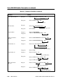
Communication Media . . . . . . . . . . . . . . . . . . . . . . . . . . . . . . . . . . . . . . . . . . . . . . . . . . . . . . . . .
NIM Block Diagram . . . . . . . . . . . . . . . . . . . . . . . . . . . . . . . . . . . . . . . . . . . . . . . . . . . . . . . . . . . . .
Timimg Considerations . . . . . . . . . . . . . . . . . . . . . . . . . . . . . . . . . . . . . . . . . . . . . . . . . . . . . . . . . .
2-2
2-3
2-4
2.2
RS-232-C Cable Installation . . . . . . . . . . . . . . . . . . . . . . . . . . . . . . . . . . . . . . . . . . . . . . . . . . . . .
2-5
2.3
Local Line Cable Installation . . . . . . . . . . . . . . . . . . . . . . . . . . . . . . . . . . . . . . . . . . . . . . . . . . . . .
2-6
Local Line Characteristics . . . . . . . . . . . . . . . . . . . . . . . . . . . . . . . . . . . . . . . . . . . . . . . . . . . . . . .
Network Cable . . . . . . . . . . . . . . . . . . . . . . . . . . . . . . . . . . . . . . . . . . . . . . . . . . . . . . . . . . . . . . . . .
Local Line Tap Housings . . . . . . . . . . . . . . . . . . . . . . . . . . . . . . . . . . . . . . . . . . . . . . . . . . . . . . . . .
Tap Housing Cable Connections . . . . . . . . . . . . . . . . . . . . . . . . . . . . . . . . . . . . . . . . . . . . . . . . .
Planning Considerations . . . . . . . . . . . . . . . . . . . . . . . . . . . . . . . . . . . . . . . . . . . . . . . . . . . . . . . . .
Local Line Tap Spacing . . . . . . . . . . . . . . . . . . . . . . . . . . . . . . . . . . . . . . . . . . . . . . . . . . . . . . . . . .
Cable Routing . . . . . . . . . . . . . . . . . . . . . . . . . . . . . . . . . . . . . . . . . . . . . . . . . . . . . . . . . . . . . . . . . .
Obstructions . . . . . . . . . . . . . . . . . . . . . . . . . . . . . . . . . . . . . . . . . . . . . . . . . . . . . . . . . . . . . . . . . . . .
2-6
2-7
2-8
2-9
2-10
2-10
2-12
2-13
Local Line Biasing . . . . . . . . . . . . . . . . . . . . . . . . . . . . . . . . . . . . . . . . . . . . . . . . . . . . . . . . . . . . . . .
2-14
Biasing Configurations . . . . . . . . . . . . . . . . . . . . . . . . . . . . . . . . . . . . . . . . . . . . . . . . . . . . . . . . . . .
Networks with only Self-biased Devices . . . . . . . . . . . . . . . . . . . . . . . . . . . . . . . . . . . . . . . . . . .
Networks with a Single Switch-biased Device . . . . . . . . . . . . . . . . . . . . . . . . . . . . . . . . . . . . .
Networks with Two or More Switch-biased Devices . . . . . . . . . . . . . . . . . . . . . . . . . . . . . . . .
Terminating the Local Line . . . . . . . . . . . . . . . . . . . . . . . . . . . . . . . . . . . . . . . . . . . . . . . . . . . . . . .
2-14
2-14
2-14
2-14
2-15
2.4
Chapter 3
Installation
3.1
General Requirements . . . . . . . . . . . . . . . . . . . . . . . . . . . . . . . . . . . . . . . . . . . . . . . . . . . . . . . . . .
3-2
3.2
Installing the NIM . . . . . . . . . . . . . . . . . . . . . . . . . . . . . . . . . . . . . . . . . . . . . . . . . . . . . . . . . . . . . . .
3-3
3.3
Inserting the Module into the Base . . . . . . . . . . . . . . . . . . . . . . . . . . . . . . . . . . . . . . . . . . . . . . .
3-4
3.4
Setting the Dipswitches . . . . . . . . . . . . . . . . . . . . . . . . . . . . . . . . . . . . . . . . . . . . . . . . . . . . . . . . . .
3-6
Selecting the Network Address . . . . . . . . . . . . . . . . . . . . . . . . . . . . . . . . . . . . . . . . . . . . . . . . . .
Selecting Network Configuration Parameters . . . . . . . . . . . . . . . . . . . . . . . . . . . . . . . . . . . . .
Other Switches . . . . . . . . . . . . . . . . . . . . . . . . . . . . . . . . . . . . . . . . . . . . . . . . . . . . . . . . . . . . . . . . .
3-6
3-7
3-11
Contents
iii
3.5
Series 500 NIM Self Tests . . . . . . . . . . . . . . . . . . . . . . . . . . . . . . . . . . . . . . . . . . . . . . . . . . . . . . . . .
3-14
Power-up Self-Test . . . . . . . . . . . . . . . . . . . . . . . . . . . . . . . . . . . . . . . . . . . . . . . . . . . . . . . . . . . . . .
Run-Time Self-Test . . . . . . . . . . . . . . . . . . . . . . . . . . . . . . . . . . . . . . . . . . . . . . . . . . . . . . . . . . . . . . .
User-Initiated Self-Test . . . . . . . . . . . . . . . . . . . . . . . . . . . . . . . . . . . . . . . . . . . . . . . . . . . . . . . . . . .
3-14
3-14
3-15
3.6
Module Login Verification . . . . . . . . . . . . . . . . . . . . . . . . . . . . . . . . . . . . . . . . . . . . . . . . . . . . . . .
3-17
3.7
Connecting the Network Cables . . . . . . . . . . . . . . . . . . . . . . . . . . . . . . . . . . . . . . . . . . . . . . . . .
3-18
Chapter 4
NIM Primitives
4.1
TIWAY I Primitives . . . . . . . . . . . . . . . . . . . . . . . . . . . . . . . . . . . . . . . . . . . . . . . . . . . . . . . . . . . . . . . .
4-2
4.2
Primitive Functions . . . . . . . . . . . . . . . . . . . . . . . . . . . . . . . . . . . . . . . . . . . . . . . . . . . . . . . . . . . . . .
4-3
4.3
Primitive Structure and Operation . . . . . . . . . . . . . . . . . . . . . . . . . . . . . . . . . . . . . . . . . . . . . . . .
4-4
Primitive Operation and Exceptions . . . . . . . . . . . . . . . . . . . . . . . . . . . . . . . . . . . . . . . . . . . . . .
Normal Operation Procedures . . . . . . . . . . . . . . . . . . . . . . . . . . . . . . . . . . . . . . . . . . . . . . . . . . .
Exception Procedures . . . . . . . . . . . . . . . . . . . . . . . . . . . . . . . . . . . . . . . . . . . . . . . . . . . . . . . . . . .
Program Transfer Procedures . . . . . . . . . . . . . . . . . . . . . . . . . . . . . . . . . . . . . . . . . . . . . . . . . . . .
4-6
4-6
4-6
4-7
Primitive Logical Groups . . . . . . . . . . . . . . . . . . . . . . . . . . . . . . . . . . . . . . . . . . . . . . . . . . . . . . . . .
4-9
Series 500 NIM Primitive Subset . . . . . . . . . . . . . . . . . . . . . . . . . . . . . . . . . . . . . . . . . . . . . . . . . . .
4-10
Primitive Field Definitions . . . . . . . . . . . . . . . . . . . . . . . . . . . . . . . . . . . . . . . . . . . . . . . . . . . . . . . .
4-11
Primitive Field Symbols . . . . . . . . . . . . . . . . . . . . . . . . . . . . . . . . . . . . . . . . . . . . . . . . . . . . . . . . . . .
Length Field – LLLL . . . . . . . . . . . . . . . . . . . . . . . . . . . . . . . . . . . . . . . . . . . . . . . . . . . . . . . . . . . . . .
Primitive Code Field – PP . . . . . . . . . . . . . . . . . . . . . . . . . . . . . . . . . . . . . . . . . . . . . . . . . . . . . . . .
Attached Device Status – HH . . . . . . . . . . . . . . . . . . . . . . . . . . . . . . . . . . . . . . . . . . . . . . . . . . . .
Descriptor Field . . . . . . . . . . . . . . . . . . . . . . . . . . . . . . . . . . . . . . . . . . . . . . . . . . . . . . . . . . . . . . . . .
Basic Data Unit – DDDD . . . . . . . . . . . . . . . . . . . . . . . . . . . . . . . . . . . . . . . . . . . . . . . . . . . . . . . . .
4-12
4-12
4-12
4-12
4-13
4-13
4.6
Data Element Types and Formats . . . . . . . . . . . . . . . . . . . . . . . . . . . . . . . . . . . . . . . . . . . . . . . .
4-14
4.7
Data Element Address Ranges . . . . . . . . . . . . . . . . . . . . . . . . . . . . . . . . . . . . . . . . . . . . . . . . . . .
4-24
4.8
Data Field Length Restrictions . . . . . . . . . . . . . . . . . . . . . . . . . . . . . . . . . . . . . . . . . . . . . . . . . . . .
4-26
4.9
Series 500 NIM Primitive Descriptions . . . . . . . . . . . . . . . . . . . . . . . . . . . . . . . . . . . . . . . . . . . . .
4-28
Exception Primitive – Code 00 . . . . . . . . . . . . . . . . . . . . . . . . . . . . . . . . . . . . . . . . . . . . . . . . . . .
Native Primitive – Code 01 . . . . . . . . . . . . . . . . . . . . . . . . . . . . . . . . . . . . . . . . . . . . . . . . . . . . . .
Status Primitive – Code 02 . . . . . . . . . . . . . . . . . . . . . . . . . . . . . . . . . . . . . . . . . . . . . . . . . . . . . . .
Configuration Primitive – Code 03 . . . . . . . . . . . . . . . . . . . . . . . . . . . . . . . . . . . . . . . . . . . . . . .
Primitive Format Configuration – Code 04 . . . . . . . . . . . . . . . . . . . . . . . . . . . . . . . . . . . . . . . .
Packed Native Primitive – Code 05 . . . . . . . . . . . . . . . . . . . . . . . . . . . . . . . . . . . . . . . . . . . . . .
Reset Secondary Device Mode – Code 06 . . . . . . . . . . . . . . . . . . . . . . . . . . . . . . . . . . . . . . .
Segment Definition – Code 07 . . . . . . . . . . . . . . . . . . . . . . . . . . . . . . . . . . . . . . . . . . . . . . . . . . .
Change State Primitive – Code 10 . . . . . . . . . . . . . . . . . . . . . . . . . . . . . . . . . . . . . . . . . . . . . . .
Read Block Primitive – Code 20 . . . . . . . . . . . . . . . . . . . . . . . . . . . . . . . . . . . . . . . . . . . . . . . . . .
Read Random Block Primitive – Code 21 . . . . . . . . . . . . . . . . . . . . . . . . . . . . . . . . . . . . . . . . .
4-28
4-30
4-31
4-32
4-33
4-34
4-34
4-35
4-36
4-37
4-38
4.4
4.5
iv
Contents
Write Block Primitive – Code 30 . . . . . . . . . . . . . . . . . . . . . . . . . . . . . . . . . . . . . . . . . . . . . . . . . .
Write Random Block Primitive – Code 31 . . . . . . . . . . . . . . . . . . . . . . . . . . . . . . . . . . . . . . . . .
Block Data Acquisition Primitive Codes 50, 51, and 52 . . . . . . . . . . . . . . . . . . . . . . . . . . . . .
Record Data Acquisition Primitive Codes 55, 56, and 57 . . . . . . . . . . . . . . . . . . . . . . . . . . .
Program Upload & Download Primitive Codes 58 and 59 . . . . . . . . . . . . . . . . . . . . . . . . . .
Summary of Primitives . . . . . . . . . . . . . . . . . . . . . . . . . . . . . . . . . . . . . . . . . . . . . . . . . . . . . . . . . . .
Appendix A
4-39
4-39
4-40
4-44
4-47
4-58
PM550 CIM Requirements
A.1
Introduction . . . . . . . . . . . . . . . . . . . . . . . . . . . . . . . . . . . . . . . . . . . . . . . . . . . . . . . . . . . . . . . . . . . .
A-2
A.2
Local Line Length . . . . . . . . . . . . . . . . . . . . . . . . . . . . . . . . . . . . . . . . . . . . . . . . . . . . . . . . . . . . . . .
A-3
A.3
Local Line Bias and Termination . . . . . . . . . . . . . . . . . . . . . . . . . . . . . . . . . . . . . . . . . . . . . . . . . .
A-4
Networks with Switch-biased Devices and CIMs . . . . . . . . . . . . . . . . . . . . . . . . . . . . . . . . . .
Networks with Only Self-biasing Devices and CIMs . . . . . . . . . . . . . . . . . . . . . . . . . . . . . . . .
A-4
A-4
Appendix B
Floating Point Numbers
B.1
Introduction . . . . . . . . . . . . . . . . . . . . . . . . . . . . . . . . . . . . . . . . . . . . . . . . . . . . . . . . . . . . . . . . . . . .
B-2
B.2
IBM Format . . . . . . . . . . . . . . . . . . . . . . . . . . . . . . . . . . . . . . . . . . . . . . . . . . . . . . . . . . . . . . . . . . . . .
B-3
B.3
IEEE Format . . . . . . . . . . . . . . . . . . . . . . . . . . . . . . . . . . . . . . . . . . . . . . . . . . . . . . . . . . . . . . . . . . . . .
B-5
Appendix C
Network Configuration Data Sheet
Appendix D
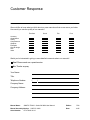
Network Evaluation Form
Appendix E
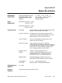
Specifications
Environmental Specifications . . . . . . . . . . . . . . . . . . . . . . . . . . . . . . . . . . . . . . . . . . . . . . . . . . . .
Power Requirements . . . . . . . . . . . . . . . . . . . . . . . . . . . . . . . . . . . . . . . . . . . . . . . . . . . . . . . . . . . .
Communications . . . . . . . . . . . . . . . . . . . . . . . . . . . . . . . . . . . . . . . . . . . . . . . . . . . . . . . . . . . . . . .
Certifications and Approvals . . . . . . . . . . . . . . . . . . . . . . . . . . . . . . . . . . . . . . . . . . . . . . . . . . . .
Technical Assistance . . . . . . . . . . . . . . . . . . . . . . . . . . . . . . . . . . . . . . . . . . . . . . . . . . . . . . . . . . . .
Appendix F
E-1
E-1
E-1
E-1
E-1
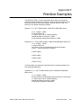
Primitive Examples
Contents
v
List of Figures
1-1 TIWAY I System Block Diagram . . . . . . . . . . . . . . . . . . . . . . . . . . . . . . . . . . . . . . . . . . . . . . . . . . . . . .
2-1
2-2
2-3
2-4
2-5
2-6
1-4
NIM Simplified Block Diagram . . . . . . . . . . . . . . . . . . . . . . . . . . . . . . . . . . . . . . . . . . . . . . . . . . . . . .
Number of Local Line Secondaries Versus Cable Length . . . . . . . . . . . . . . . . . . . . . . . . . . . . .
TIWAY I Tap Housing . . . . . . . . . . . . . . . . . . . . . . . . . . . . . . . . . . . . . . . . . . . . . . . . . . . . . . . . . . . . . . .
Tap Spacing Examples . . . . . . . . . . . . . . . . . . . . . . . . . . . . . . . . . . . . . . . . . . . . . . . . . . . . . . . . . . . .
Local Line with Two or More Switch-biased NIMs . . . . . . . . . . . . . . . . . . . . . . . . . . . . . . . . . . . .
Terminating the Local Line . . . . . . . . . . . . . . . . . . . . . . . . . . . . . . . . . . . . . . . . . . . . . . . . . . . . . . . . .
2-3
2-7
2-9
2-11
2-15
2-16
3-1 Keying the Series 500 NIM . . . . . . . . . . . . . . . . . . . . . . . . . . . . . . . . . . . . . . . . . . . . . . . . . . . . . . . . . .
3-2 Installing the NIM in the I/O Base . . . . . . . . . . . . . . . . . . . . . . . . . . . . . . . . . . . . . . . . . . . . . . . . . . .
3-3 NIM Switches and LEDs . . . . . . . . . . . . . . . . . . . . . . . . . . . . . . . . . . . . . . . . . . . . . . . . . . . . . . . . . . . .
3-4
3-5
3-8
4-1
4-2
4-3
4-4
4-5
4-6
4-7
4-8
4-9
4-10
4-11
4-12
4-13
4-14
4-15
Basic Primitive Structure . . . . . . . . . . . . . . . . . . . . . . . . . . . . . . . . . . . . . . . . . . . . . . . . . . . . . . . . . . .
Binary Weight of the Fields . . . . . . . . . . . . . . . . . . . . . . . . . . . . . . . . . . . . . . . . . . . . . . . . . . . . . . . . .
Primitive Request and Response Field Format . . . . . . . . . . . . . . . . . . . . . . . . . . . . . . . . . . . . . . .
Discrete Data Element Format . . . . . . . . . . . . . . . . . . . . . . . . . . . . . . . . . . . . . . . . . . . . . . . . . . . . .
Packed Discrete Data Element Format . . . . . . . . . . . . . . . . . . . . . . . . . . . . . . . . . . . . . . . . . . . . .
Forced Word Data Element Format . . . . . . . . . . . . . . . . . . . . . . . . . . . . . . . . . . . . . . . . . . . . . . . .
Forced Discrete and CR Data Element Format . . . . . . . . . . . . . . . . . . . . . . . . . . . . . . . . . . . . . .
Secondary System Status Data Element Format . . . . . . . . . . . . . . . . . . . . . . . . . . . . . . . . . . . . .
Loop Status Data Element Format . . . . . . . . . . . . . . . . . . . . . . . . . . . . . . . . . . . . . . . . . . . . . . . . . .
Loop Control Flag Data Element Format . . . . . . . . . . . . . . . . . . . . . . . . . . . . . . . . . . . . . . . . . . .
Ramp/Soak Status Data Element Format . . . . . . . . . . . . . . . . . . . . . . . . . . . . . . . . . . . . . . . . . .
Loop Mode Data Element Format . . . . . . . . . . . . . . . . . . . . . . . . . . . . . . . . . . . . . . . . . . . . . . . .
Ramp/Soak Step Data Element Format . . . . . . . . . . . . . . . . . . . . . . . . . . . . . . . . . . . . . . . . . . .
Analog Alarm Variable Flag Data Element Format . . . . . . . . . . . . . . . . . . . . . . . . . . . . . . . . .
Analog Alarm Control Flag Data Element Format . . . . . . . . . . . . . . . . . . . . . . . . . . . . . . . . . .
4-5
4-6
4-11
4-16
4-17
4-17
4-18
4-18
4-19
4-20
4-21
4-21
4-22
4-22
4-23
A-1 Local Line Bias and Termination . . . . . . . . . . . . . . . . . . . . . . . . . . . . . . . . . . . . . . . . . . . . . . . . . . . .
A-5
B-1 IBM Floating Point Representation . . . . . . . . . . . . . . . . . . . . . . . . . . . . . . . . . . . . . . . . . . . . . . . . . .
B-2 IEEE Floating Point Representation . . . . . . . . . . . . . . . . . . . . . . . . . . . . . . . . . . . . . . . . . . . . . . . . . .
B-4
B-6
vi
Contents
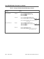
List of Tables
1-1 Primitive Support in NIM Software Releases . . . . . . . . . . . . . . . . . . . . . . . . . . . . . . . . . . . . . . . . . .
1-7
2-1 RS-232-C Connections . . . . . . . . . . . . . . . . . . . . . . . . . . . . . . . . . . . . . . . . . . . . . . . . . . . . . . . . . . . . .
2-2 Pin Assignments of Local Line Connectors . . . . . . . . . . . . . . . . . . . . . . . . . . . . . . . . . . . . . . . . . .
2-5
2-6
3-1 Network Address Selection . . . . . . . . . . . . . . . . . . . . . . . . . . . . . . . . . . . . . . . . . . . . . . . . . . . . . . . .
3-2 Address Examples . . . . . . . . . . . . . . . . . . . . . . . . . . . . . . . . . . . . . . . . . . . . . . . . . . . . . . . . . . . . . . . . .
3-3 Network Data Rate Switch Settings . . . . . . . . . . . . . . . . . . . . . . . . . . . . . . . . . . . . . . . . . . . . . . . . .
3-6
3-7
3-9
4-1
4-2
4-3
4-4
4-5
4-6
4-7
4-8
4-9
Logical Primitive Assignment . . . . . . . . . . . . . . . . . . . . . . . . . . . . . . . . . . . . . . . . . . . . . . . . . . . . . . .
Series 500 NIM Primitive Subset . . . . . . . . . . . . . . . . . . . . . . . . . . . . . . . . . . . . . . . . . . . . . . . . . . . . .
Summary of Primitive Field Symbols . . . . . . . . . . . . . . . . . . . . . . . . . . . . . . . . . . . . . . . . . . . . . . . . .
Data Element Types and Formats . . . . . . . . . . . . . . . . . . . . . . . . . . . . . . . . . . . . . . . . . . . . . . . . . .
Data Element Address Ranges . . . . . . . . . . . . . . . . . . . . . . . . . . . . . . . . . . . . . . . . . . . . . . . . . . . . .
Maximum Read Primitive Byte Length . . . . . . . . . . . . . . . . . . . . . . . . . . . . . . . . . . . . . . . . . . . . . .
Maximum Write Primitive Byte Length . . . . . . . . . . . . . . . . . . . . . . . . . . . . . . . . . . . . . . . . . . . . . . .
Summary of Primitives . . . . . . . . . . . . . . . . . . . . . . . . . . . . . . . . . . . . . . . . . . . . . . . . . . . . . . . . . . . . .
Summary of Primitives (Extended Addressing) . . . . . . . . . . . . . . . . . . . . . . . . . . . . . . . . . . . . . . .
4-9
4-10
4-12
4-14
4-25
4-26
4-27
4-59
4-62
B-1 IEEE Conversions . . . . . . . . . . . . . . . . . . . . . . . . . . . . . . . . . . . . . . . . . . . . . . . . . . . . . . . . . . . . . . . . . .
B-5
Contents
vii
Preface
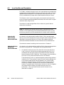
Manual Overview
Manual
Organization
This manual contains the information necessary to install and operate the
Series 500 Network Interface Module (NIM). The following information is
provided.
•
NIM specifications
•
Installation and testing procedures
•
Operating instructions and descriptions
•
SIMATIC TIWAY I primitive descriptions and examples
This manual is organized as follows:
•
CHAPTER 1 — TIWAY I OVERVIEW contains an overview of the
TIWAY I network and an explanation of how the Series 500 NIM
operates within this network. NIM specifications are also defined.
•
CHAPTER 2 — NETWORK DESIGN CONSIDERATIONS describes
possible network design configurations, and the use of modems with
TIWAY I. Local Line cabling, biasing, and termination are also
discussed.
•
CHAPTER 3 — INSTALLATION describes NIM installation and
diagnostic procedures.
•
CHAPTER 4 — NIM PRIMITIVES describes NIM operation and the
primitive subset supported by the NIM.
•
APPENDIX A — PM550 CIM REQUIREMENTS contains procedures
for Local Line biasing and termination for networks that contain a
mixture of Series 500 NIMs and SIMATIC PM550 Computer
Interface Modules (CIM).
•
APPENDIX B — FLOATING POINT NUMBERS defines floating point
representation used in the TIWAY network.
•
APPENDIX C — NETWORK CONFIGURATION DATA SHEET
contains a form that will help you plan your network.
•
APPENDIX D — NETWORK EVALUATION FORM contains a TIWAY
network evaluation form. You can submit the completed form to
Siemens for a free network evaluation.
SIMATIC TIWAY I Series 500 NIM User Manual
Preface
ix
Related
Publications
•
APPENDIX E — SPECIFICATIONS provides general specifications for
the Series 500 NIM.
•
APPENDIX F — PRIMITIVE EXAMPLES provides a simple primitive
example in normal and extended addressing modes.
The following publications contain additional information on TIWAY I and
TIWAY I compatible products. To order these publications, contact your
distributor or sales office. If you need assistance in contacting your
distributor or sales office in the United States, call 1–800–964–4114.
Manual Title
SIMATIC TIWAY I Systems Manual
TIWAY–8101
SIMATIC TIWAY I Host Adapter User Manual
TIWAY–8102
SIMATIC TIWAY I Host Software Programming Manual
TIWAY–8105
SIMATIC PM550 NIM User Manual
550–8110
SIMATIC 5TI NIM User Manual
5TI–8105
Unilink Host Adapter User Manual
x
Preface
Manual
Number
TIWAY–8121
SIMATIC TIWAY I Series 500 NIM User Manual
Chapter 1
TIWAY I Overview
1.1
TIWAY I System Overview . . . . . . . . . . . . . . . . . . . . . . . . . . . . . . . . . . . . . . . . . . . . . . . . . . . . . . . .
1-2
TIWAY I Options . . . . . . . . . . . . . . . . . . . . . . . . . . . . . . . . . . . . . . . . . . . . . . . . . . . . . . . . . . . . .
System Block Diagram . . . . . . . . . . . . . . . . . . . . . . . . . . . . . . . . . . . . . . . . . . . . . . . . . . . . . .
TIWAY I Universal Command Language, UCL . . . . . . . . . . . . . . . . . . . . . . . . . . . . . . . . .
The Series 500 NIM . . . . . . . . . . . . . . . . . . . . . . . . . . . . . . . . . . . . . . . . . . . . . . . . . . . . . . . . . .
Series 500 NIM Features . . . . . . . . . . . . . . . . . . . . . . . . . . . . . . . . . . . . . . . . . . . . . . . . . . . . .
Series 500 NIM Software Releases . . . . . . . . . . . . . . . . . . . . . . . . . . . . . . . . . . . . . . . . . . . .
1-3
1-3
1-5
1-5
1-6
1-6
SIMATIC TIWAY I Series 500 NIM User Manual
TIWAY I Overview
1-1
1.1
TIWAY I System Overview
TIWAY I is an industrial Local Area Network designed to satisfy today’s
factory and plant requirements for data acquisition and control of
manufacturing processes. It is a significant enhancement of the Siemens
“Local Line,” which has supported the PM550 Programmable Controllers
and DS 990 computer products since 1980.
The TIWAY I network provides a reliable and flexible communication
architecture. Two communication media options are available:
•
RS-232-C/423 — provides modem interface for large geographic
coverage.
•
Local Line — provides high noise immunity for networks up to 25,000
feet (7620 meters).
Redundancy is supported for either choice of media. TIWAY I uses
High-level Data Link Control (HDLC) protocol with CRC-16 error-checking
and message-length error-checking, providing reliable network
communication.
Throughout this manual, the following networking terms are used.
1-2
TIWAY I Overview
•
Primary — the HDLC network manager
•
Secondary — the device operating as an HDLC secondary slave (NIMs,
UNILINK Secondary Adapters)
•
Attached device — controller, robot, etc. (Siemens controller connected
to the NIM, robot connected to a UNILINK Secondary Adapter)
SIMATIC TIWAY I Series 500 NIM User Manual
TIWAY I Options
System Block
Diagram
TIWAY I network products provide a number of user-selectable options.
•
Baud rates are selectable from 110 baud to 115.2 K baud.
•
TIWAY I devices can operate with modems in either full or half duplex
mode, synchronously or asynchronously.
•
Both NRZ and NRZI data encoding are available.
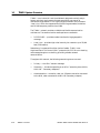
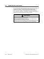
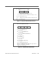
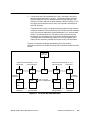
Figure 1-1 illustrates the basic system block diagram of a TIWAY I Network.
System components include:
•
Host System Interfaces (including Host Adapters, Gateways, and
Network Control Modules)
•
Siemens Programmable Controller Network Interface Modules (NIMs)
•
UNILINK Secondary Adapters for interfacing non-Siemens products
to the TIWAY I Network
SIMATIC TIWAY I Series 500 NIM User Manual
TIWAY I Overview
1-3
TIWAY I System Overview (continued)
!
Figure 1-1 TIWAY I System Block Diagram
1-4
TIWAY I Overview
SIMATIC TIWAY I Series 500 NIM User Manual
TIWAY I Universal
Command
Language, UCL
TIWAY I provides a Universal Command Language for all communication
on the network. The UCL consists of a set of high-level request/response
transactions known as Primitives. Primitives are used for:
•
Reading and writing data
•
Acquiring status of devices attached to the network
•
Performing control operations on attached devices
Host Systems (computers or other intelligent devices) issue requests
(Primitives) to Network Interface Modules and Secondary Adapters. The
secondary interfaces then perform the requested operation on their attached
device and return the appropriate response to the Host Devices to complete
the transaction. (See Figure 1-1.)
The Series 500 NIM
The Series 500 NIM is the TIWAY I Network Interface Module for the
Siemens Series 500 Programmable Controllers. See Chapter 3 for a specific
listing of controllers supported by the Series 500 NIM.
The Series 500 NIM, which occupies two slots of a Series 500 I/O base,
provides redundant TIWAY I communication ports. Each of the following
models supports a specific type of network communication media.
Part Number
Port A
Port B
PPX:500–5039
Local Line
Local Line
PPX:500–5040
RS-232-C/423
RS-232-C/423
The RS-232-C/423 media interface is configured as Data Terminal
Equipment (DTE) and is used to connect the NIM to Data Communication
Equipment (DCE) for operation with modems. This interface uses RS-423
drivers and receivers and operates at RS-423-A signal levels (+5 or –5 volts;
these levels are also RS-232-C compatible). The pin assignments for the
RS-232-C port are given in Table 2–1.
The Local Line interface is a differential line port for use with shielded
twisted pair cable. The Local Line interface provides line isolation and high
noise immunity for installations up to 10,000 feet (25,000 feet depending on
system loading and baud rate selection).
SIMATIC TIWAY I Series 500 NIM User Manual
TIWAY I Overview
1-5
TIWAY I System Overview (continued)
Series 500 NIM
Features
Series 500 NIM
Software Releases
The Series 500 NIM provides several features which ensure maximum
network signal integrity.
•
Each communication port is provided with a “jabberstop” circuit to
disable the port’s transmitter in the event of a communication port
failure. Such failures can cause continuous network transmission
which would dominate the communication channel.
•
Built–in self tests guard against failure of the NIM itself. Chapter 3
provides a complete description of these built-in tests.
To date there have been four releases of Series 500 NIM software.
Releases 2.1, 2.2, and 3.0 provide enhancements to release 1.1.
Release 1.1 — initial release that provides basic primitive and data type
support for 520 and 530 controllers. In this release, the data element range
configuration is fixed.
Release 2.1 — contains all capability of release 1.1 and adds the following:
•
Extended addressing
•
Automatic data element range configuration
•
Support for the 560/65 controllers
•
I/O force data types
Release 2.2 — contains all capability of release 2.1 and adds the following:
•
Support for CR force operations
Release 3.0 — contains all capability of release 2.2 and adds the following:
•
Program upload/download support
•
Allows data type 35 (loop mode) to be read or written
•
Minor software error corrections
If the product release level does not appear on the product I.D. label, call
the Siemens Technical Services Group at (423) 461–2501 for assistance.
They will need the unit serial number to determine the release level.
1-6
TIWAY I Overview
SIMATIC TIWAY I Series 500 NIM User Manual
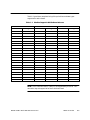
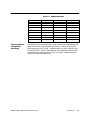
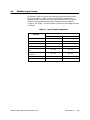
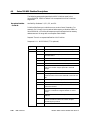
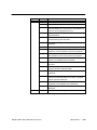
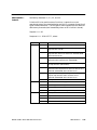
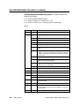
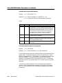
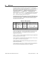
Table 1-1 provides a complete listing of the primitives and data types
supported in each release.
Table 1-1 Primitive Support in NIM Software Releases
Release 1.1
Releases 2.1 and 2.2
Release 3.0
Primitive
TT Types
Primitive
TT Types
Primitive
TT Types
0
0
0
0
A
0
0
A
1
1
1
1
B
1
1
B
2
3
2
2
C
2
2
C
3
4
3
3
D
3
3
D
4
5
4
4
E
4
4
E
10
6
5
5
F
5
5
F
20
7
10
6
10
6
6
10
30
8
20
7
11
7
7
11
50
9
21
8
12
10
8
12
51
A
30
9
17
20
9
17
52
E
31
20
4A
21
20
4A
F
50
60
6C
30
60
6C
10
51
70
74
31
70
74
11
52
76
7A
50
76
7A
12
55
7C
84
51
7C
84
56
87
8A
52
87
8A
57
55
56
57
58
59
NOTE: The Primitives listed in Table 1-1 are supported by the NIM. Your
controller may not support all of the Primitives listed.
SIMATIC TIWAY I Series 500 NIM User Manual
TIWAY I Overview
1-7
Chapter 2
Network Design Considerations
2.1
TIWAY I Network Configuration . . . . . . . . . . . . . . . . . . . . . . . . . . . . . . . . . . . . . . . . . . . . . . . . . . .
2-2
Communication Media . . . . . . . . . . . . . . . . . . . . . . . . . . . . . . . . . . . . . . . . . . . . . . . . . . . . .
NIM Block Diagram . . . . . . . . . . . . . . . . . . . . . . . . . . . . . . . . . . . . . . . . . . . . . . . . . . . . . . . . .
Timing Considerations . . . . . . . . . . . . . . . . . . . . . . . . . . . . . . . . . . . . . . . . . . . . . . . . . . . . . .
2-2
2-3
2-4
2.2
RS-232-C Cable Installation . . . . . . . . . . . . . . . . . . . . . . . . . . . . . . . . . . . . . . . . . . . . . . . . . . . . .
2-5
2.3
Local Line Cable Installation . . . . . . . . . . . . . . . . . . . . . . . . . . . . . . . . . . . . . . . . . . . . . . . . . . . . .
2-6
Local Line Characteristics . . . . . . . . . . . . . . . . . . . . . . . . . . . . . . . . . . . . . . . . . . . . . . . . . .
Network Cable . . . . . . . . . . . . . . . . . . . . . . . . . . . . . . . . . . . . . . . . . . . . . . . . . . . . . . . . . . . . .
Local Line Tap Housings . . . . . . . . . . . . . . . . . . . . . . . . . . . . . . . . . . . . . . . . . . . . . . . . . . . . .
Tap Housing Cable Connections . . . . . . . . . . . . . . . . . . . . . . . . . . . . . . . . . . . . . . . . . . . .
Planning Considerations . . . . . . . . . . . . . . . . . . . . . . . . . . . . . . . . . . . . . . . . . . . . . . . . . . . .
Local Line Tap Spacing . . . . . . . . . . . . . . . . . . . . . . . . . . . . . . . . . . . . . . . . . . . . . . . . . . . . .
Cable Routing . . . . . . . . . . . . . . . . . . . . . . . . . . . . . . . . . . . . . . . . . . . . . . . . . . . . . . . . . . . . .
Obstructions . . . . . . . . . . . . . . . . . . . . . . . . . . . . . . . . . . . . . . . . . . . . . . . . . . . . . . . . . . . . . . .
2-6
2–7
2–8
2–9
2–10
2–10
2–12
2–13
Local Line Biasing . . . . . . . . . . . . . . . . . . . . . . . . . . . . . . . . . . . . . . . . . . . . . . . . . . . . . . . . . . . . . . .
2-14
Biasing Configurations . . . . . . . . . . . . . . . . . . . . . . . . . . . . . . . . . . . . . . . . . . . . . . . . . . . . . .
Networks with only Self-biased Devices . . . . . . . . . . . . . . . . . . . . . . . . . . . . . . . . . . . . . .
Networks with a Single Switch-biased Device . . . . . . . . . . . . . . . . . . . . . . . . . . . . . . . . .
Networks with Two or More Switch-biased Devices . . . . . . . . . . . . . . . . . . . . . . . . . . .
Terminating the Local Line . . . . . . . . . . . . . . . . . . . . . . . . . . . . . . . . . . . . . . . . . . . . . . . . . .
2–14
2–14
2–14
2–14
2–15
2.4
SIMATIC TIWAY I Series 500 NIM User Manual
Network Design Considerations
2-1
2.1
TIWAY I Network Configuration
TIWAY I is a multi-drop communication network which consists of a main
trunk cable (the “spine”) and dropline cables. The network can connect up to
254 secondaries (e.g., Series 500 controllers) to a host computer. The Series
500 NIM provides the interface to the network host, enabling the host and
the controller to communicate with each other.
Communication
Media
The following signal-transmission media are supported by TIWAY I:
•
RS-232-C/423 dedicated lease-line modem interface in which no dial-up
is necessary, providing extended (cross-continental) geographic
coverage.
•
RF or short-haul modem link-ups (cross-plant or cross-town coverage).
•
Siemens Local Line (up to 25,000 feet).
NOTE: Media redundancy is supported for RS-232-C and Local Line NIMs.
TIWAY I does not, however, directly support dial-up modems which require
Modem Control Commands for communication switchover. This can be done,
but specific equipment is required to dial the remote number from the host
device.
In order to achieve true redundancy, you must have a completely redundant
network (network trunk lines and drop lines).
The selection of the network communication media depends primarily upon
the geographic distance to be spanned. The main TIWAY I trunk, called the
Local Line, can be up to 10,000 feet long (25,000 feet depending on system
loading and baud rate selection), and can have up to 254 droplines. Each
dropline can be up to 100 feet long. For distances exceeding 25,000 feet,
RS-232-C/423 media interfaces and modems should be used.
NOTE: The proper installation of a communication network requires careful
planning and design. If you need assistance, a free site survey is available
from Siemens. Simply fill out and return the enclosed “TIWAY I Network
Evaluation Form” (Appendix D).
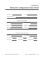
Also included with this manual is a “TIWAY I Network Configuration Data
Sheet” (Appendix C). This will assist you in maintaining a complete,
up-to-date record of the configuration of your network, which is particulary
important if you are using several different types of secondaries.
2-2
Network Design Considerations
SIMATIC TIWAY I Series 500 NIM User Manual
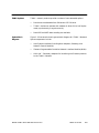
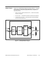
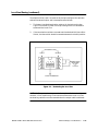
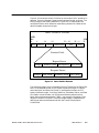
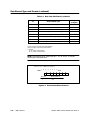
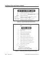
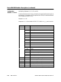
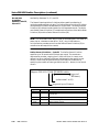
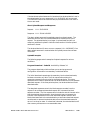
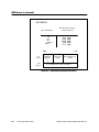
NIM Block Diagram
Figure 2-1 is a simplified block diagram of the Series 500 NIM. The media
interface blocks are intentionally left unlabeled because the type of media
interface depends on which NIM model you are using. The blocks are
described as follows.
•
Special Function Interface Controller (SFIC) — delivers and receives
controller commands.
•
NIM controller — translates the controller commands and responses.
•
Communications controller — supervises data transactions between
the NIM and the network host.
"#$%&
#"'"% ()"
%+
%#%)*
)"
%$"
#%
,%
-"
-(
"
)
'(#
%
#"'"
%#%)*
)"
%#%))"
" #%
"#$%&
%+
" Figure 2-1 NIM Simplified Block Diagram
SIMATIC TIWAY I Series 500 NIM User Manual
Network Design Considerations
2-3
TIWAY I Network Configuration (continued)
The basic difference in the NIM models is the configuration of the media
interface cards. Examples of the possible application of the different models
are as follows:
Timimg
Considerations
•
If you want media redundancy for a dedicated line (lease-line) modem,
or an RF (short-haul) modem, use PPX:500–5040 which supports
RS-232-C/423 on both Port A and Port B.
•
If you want media redundancy for a Local Line installation, use
PPX:500–5039 which supports Local Line on both ports.
If you use the Series 500 NIM with a dedicated short-haul RF modem, the
NIM has a one-second time-out between the transmission of its RS-232-C
Request to Send (RTS) and the RS-232-C Clear to Send (CTS) response.
This time-out value is set at one second to enable the RF device to switch
from receive to transmit without losing access to the transmission media.
NOTE: This extended time-out feature is an important consideration when
selecting a TIWAY I-compatible RF Modem. Transmitter/Receiver
turnaround time must be less than the one-second network time-out.
An additional half-second delay from Clear to Send (CTS) to start of
transmission can be added by setting the Keydelay Switch to the OPEN
(left) position. This may be required to allow the transmitter to reach full
power before start of transmission. There is also a one-second wait period
for DCD to turn off in a half-duplex modem.
2-4
Network Design Considerations
SIMATIC TIWAY I Series 500 NIM User Manual
2.2
RS-232-C Cable Installation
The physical layer in TIWAY I provides a modem interface for synchronous
or asynchronous modems at data transmission rates up to 115.2K bits per
second. The modem interface provides standard signals, as defined in
Table 2-1, for control of two-way alternate data transmission using both half
and full duplex modems. The modem interface is a standard “Type E” DTE
configuration as defined in Section 5 of EIA RS-232-C. This interface uses a
male (plug) 25-pin D-type connector on the communication cable. The
circuits and pin assignments for the RS-232-C connector are shown in
Table 2-1.
Table 2-1 RS-232-C Connections
Pin
ISO #
1
101
AA –
Protective Ground (chassis)
2
103
BA –
Transmitted Data
3
104
BB –
Received Data
4
105
CA –
Request to Send (RTS)
5
106
CB –
Clear to Send (CTS)
6
107
CC –
Data Set Ready (DSR)
7
102
AB –
Signal Ground
8
109
CF –
Received Line Signal Detector/
Data Carrier Detect (RLSD/DCD)
15
114
DB –
Transmitter Signal Element Timing
17
115
DD –
Receiver Signal Element Timing
20
108/2
CD –
Data Terminal Ready (DTR)
SIMATIC TIWAY I Series 500 NIM User Manual
RS–232-C Name – Function
Network Design Considerations
2-5
2.3
Local Line Cable Installation
The following paragraphs describe Local Line characteristics and
installation guidelines.
Local Line
Characteristics
The TIWAY I Local Line is a physical signaling technique (baseband,
differential current drive) which operates over shielded, twisted-pair
cabling. The Local Line cable may be up to 25,000 feet long, depending on
loading and baud rate selection. It uses tap housings to simplify the
addition of connections to TIWAY I. The Local Line is designed to operate
with shielded, twisted-pair cable which has a characteristic impedance of
124 ohms.
The interface is a male, 9-pin D-type receptacle with pin assignments as
shown in Table 2-2.
Table 2-2 Pin Assignments of Local Line Connectors
Pin
Name
Description
1
No connection
2
No connection
3
Shield
Cable shield and signal common
4
No connection
5
No connection
6
LLM+
Positive biased signal line
7
No connection
8
No connection
9
LLM–
Negative based signal line
NOTE: If you need Local Line cable redundancy, you will need one
PPX:500–5039 NIM, two separate twisted pair cables, and a T-Tap and
dropline for each port on the NIM. All taps and connectors are supplied with
the Local Line, but extras may be necessary for cable splicing. Suggested
routing procedures for redundant Local Line cabling are listed later in this
section.
2-6
Network Design Considerations
SIMATIC TIWAY I Series 500 NIM User Manual
Network Cable
The TIWAY I local line network cable consists of a main cable or spine with
droplines or taps for each Secondary. Interrelated network variables having
direct influence upon network performance are:
•
Maximum trunk cable length
•
Cable type
•
Tap length
•
Tap spacing
•
Number of Secondaries
•
Maximum baud rates
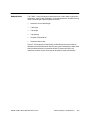
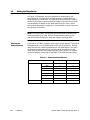
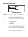
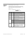
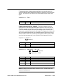
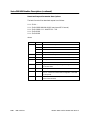
Figure 2-2 illustrates the relationship of cable distance to the number of
Secondaries for different baud rates for two types of twisted pair cable. Note
that the cable distance (in thousands of feet) is shown vertically; the
maximum number of units that may be attached is shown horizontally.
SIMATIC TIWAY I Series 500 NIM User Manual
Network Design Considerations
2-7
Figure 2-2 Number of Local Line Secondaries Versus Cable Length
2-8
Network Design Considerations
SIMATIC TIWAY I Series 500 NIM User Manual
Local Line Cable Installation (continued)
As shown in Figure 2-2, when you use Belden 9860 cable (or its
equivalent), up to 75 stations can be attached to a network operating at 38K
bps and having a spine length of 20,000 feet. At 115.2K bps, the maximum
length of a Local Line network having 254 stations is 10,000 feet.
Local Line Tap
Housings
The Local Line primarily consists of two items:
•
Twisted-pair cabling
•
Tap housings
Siemens recommends Belden 9860 twisted pair cabling, or its equivalent,
for use as the Local Line network spine. Belden 9271, or its equivalent,
should be used for the dropline. Brands other than those listed here will be
specified by Siemens upon request.
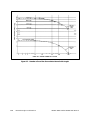
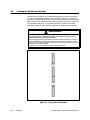
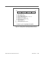
The tap housing, shown in Figure 2-3, is made by Siemens specifically for
its Local Line network. The tap housing can be mounted rigidly to a NEMA
panel or other enclosure. It could also be used to splice cables in a cable tray
without being rigidly mounted. The tap housing not only allows an orderly
connection to the TIWAY I network, but also contains terminating resistors,
resists moisture, relieves strain, and provides noise isolation for attached
cabling.
Tap housings are included for each Local Line port; however, extras may be
ordered from your distributor. Order part number PPX:500–5606.
SIMATIC TIWAY I Series 500 NIM User Manual
Network Design Considerations
2-9
Figure 2-3 TIWAY I Tap Housing
Tap Housing Cable
Connections
With the cover removed from the PPX:500–5606 Tap Housing, note that
there are three sets of terminals, and that each set is labelled G, W, and B.
(See Figure 2-3.) One set of these terminals is for the incoming Local Line
twisted pair; the center set is for the drop line; and the remaining set is
used to connect the Local Line to the following node, or to terminate the
Local Line if the Tap Housing is the last one on the network trunk.
For consistency in installation, always connect the LLM+ (Pin 6 of the Local
Line Connector) to the white strand of the twisted pair and to the terminal
marked “W” in the Tap Housing. Connect the blue strand to the LLM– (Pin
9 of the Local Line Connector) and to the terminal marked “B” in the Tap
Housing. The Cable Shield and Signal Common should be connected to Pin
3 of the Local Line connector and to terminal “G” inside the Tap Housing.
2-10
Network Design Considerations
SIMATIC TIWAY I Series 500 NIM User Manual
Local Line Cable Installation (continued)
Planning
Considerations
Local Line Tap
Spacing
Some major points to consider during the planning phase of a Local Line
network are as follows:
•
From the start, allow for system growth. This means making provisions
for the attachment of additional computing devices by routing cables
through all probable areas of future plant expansion.
•
Always make the network flexible enough to allow for rearrangement of
plant equipment.
•
Since network system noise is usually picked up by its interconnecting
wiring, steps should be taken at the outset to bypass or eliminate noise
sources such as large motor starters, high current switches, and
transformers.
•
If cable redundancy is desired, the two cables should never be routed
along the same path, since the environmental and other factors which
disable one cable will very likely disable the second.
•
A detailed record of design and routing should be created and
maintained. This record should be complete enough to enable a user to
trace and physically locate all cable paths and hardware components.
To calculate the the minimum distance between tap nodes, use the length of
the dropline at the last tap node. A tap node consists of either a single tap
on the TIWAY I trunk cable or a pair of taps separated by less than the
minimum tap node separation distance. The minimum distance between a
given tap node and the next tap node on the network is equal to one-half the
length of the longer drop line at the given node.
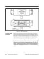
No limit is placed upon the number of NIMs that can be daisy-chained to
form a drop line off the main trunk as long as the resulting drop length is no
greater than 100 feet. Figure 2-4 illustrates three typical examples of tap
spacing.
SIMATIC TIWAY I Series 500 NIM User Manual
Network Design Considerations
2-11
Figure 2-4 Tap Spacing Examples
2-12
Network Design Considerations
SIMATIC TIWAY I Series 500 NIM User Manual
Local Line Cable Installation (continued)
Cable Routing
Cable routing should be planned as if the path between all stations on the
network were free of obstructions. Next, modify the first routing to account
for obstructions, then calculate the amount of cable needed.
!
CAUTION
All local and national electrical and fire codes should be observed when
installing wiring.
Failure to observe coding requirements could result in electrical or fire hazards.
In general, there are three types of network cabling routes:
•
Under-floor
•
In-ceiling
•
Surface ducting
Any choice of these three routes may be used on a single network. The
choice is often determined by whether the building (or buildings) in which
the network is being installed is new construction, or is an existing building.
The following paragraphs describe some of the advantages and
disadvantages of each type of cable routing.
Under-floor Routing. For under-floor routing, the cable can be enclosed
within ducts or, with raised flooring, in the “open air.” Under-floor systems
enclosed in ducts are usually expensive, and while they are better-protected
against unauthorized taps than are “open air” systems, they often make
future expansion of the network more difficult and expensive.
“Open air” under-floor cabling systems usually provide good access and
allow maximum network expansion and flexibility.
In-ceiling Routing. For in-ceiling routing, network cables are usually
supported in troughs or with hooks and clamps every 10 or 15 feet.
In-ceiling installations provide flexibility, usually cost less, and provide easy
access.
In-ceiling cable networks are not always practical. In-ceiling installations
can be difficult and sometimes dangerous in areas without drop ceilings (or
that have unusually high ceilings). Also, closed ceiling systems usually trap
dust and other debris, which makes cable maintenance difficult.
SIMATIC TIWAY I Series 500 NIM User Manual
Network Design Considerations
2-13
Surface Duct Routing. Surface ducting for network cabling is usually
installed along the baseboards or is attached to walls at desktop height.
While surface ducting protects cables from both physical and EMI effects, it
may also require that network computing devices be positioned near a wall.
Obstructions
Aside from physical obstructions such as posts, walls, and partitions,
electrical interference should also be avoided.
In general, network cabling should never come into direct contact with any
electrical conductor, and if cabling is installed inside a conduit, the conduit
should be grounded in accordance with applicable electrical codes. Keep at
least three feet between all network cabling and the following:
2-14
•
Power lines carrying 440 volts or greater
•
Generators
•
Electric motors
•
Transformers
•
Electric welders
•
Induction furnaces and heaters
•
Rectifiers
•
All sources of microwave radiation
•
Fluorescent lighting
•
Teletypes
Network Design Considerations
SIMATIC TIWAY I Series 500 NIM User Manual
2.4
Local Line Biasing
The TIWAY I Local Line is designed to operate with shielded, twisted-pair
cable which has a characteristic impedance of 124 ohms. In certain network
configurations, the Local Line must be biased to raise its noise immunity
and to prevent oscillations of receivers connected to the line.
In all configurations, the Local Line must be properly terminated at both
ends of the trunk to prevent an impedance mismatch which could result in
signal reflections on the line.
The need to apply a bias voltage to the Local Line depends upon the
interface configuration of your network.
Biasing
Configurations
Three different Local Line media interface combinations exist, based upon
the number and type of interface devices. Possible combinations are:
•
Installations consisting solely of self-biased devices.
•
Installations consisting of both switch-biased and self-biased devices.
•
Installations with PM550 CIMs.
NOTE: This section covers self-biased and switch-biased configurations only.
Appendix A discusses biasing and terminating a Local Line having all three
types of devices.
Networks with only
Self-biased
Devices
This configuration exists when all TIWAY I Devices on the network are
self-biasing (i.e., they do not have a bias switch). In this case, the position on
the line of the interface devices does not matter.
Networks with a
Single
Switch-biased
Device
This configuration exists when only one TIWAY I Device on the Local Line
has the bias switch, and all other devices are self-biasing. The position of
the switch-biased device on the line does not matter, but its bias switch
must be ON (downward position).
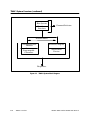
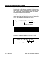
Networks with Two
or More
Switch-biased
Devices
This configuration exists when multiple switch-biased TIWAY I Devices are
attached to the network, and they should be positioned as described in the
following paragraphs.
If two or more devices having the bias switch are attached, place one at each
end of the Local Line, and turn on each bias switch.
All other devices having a bias switch can then be placed anywhere on the
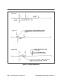
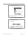
network, with the bias switches turned OFF. See Figure 2-5.
SIMATIC TIWAY I Series 500 NIM User Manual
Network Design Considerations
2-15
)%))
"
" %')%))
"
" %')%))
"
-
$
#%''
%))%#"
"% . "/
"
$
#*-
"
$
#*-
"
-
$
#%
-
$
#%
Figure 2-5 Local Line with Two or More Switch-biased NIMs
!
CAUTION
Excessive noise can enter the NIM if a switch-biased local line interface port is
unused, for instance in a case where no redundant local line is installed.
Turn on the bias switch on the unused port to prevent the entry of noise into the
NIM.
Terminating the
Local Line
The Siemens Local Line must be properly terminated at both ends of the
trunk to prevent a possible impedance mismatch which could result in
signal reflections back along the line. Termination is required regardless of
the number or type of devices attached to the network.
NOTE: In the special case of a PM550 using a CIM as its interface to the
network, see Appendix A for detailed line biasing and termination
instructions, which vary from those listed here.
2-16
Network Design Considerations
SIMATIC TIWAY I Series 500 NIM User Manual
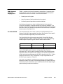
Local Line Biasing (continued)
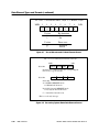
Termination of the Local Line must be at the tap housings at the extreme
ends of the network spine, and is accomplished as follows:
1.
The factory-installed termination resistors in the tap housing (see
Figure 2-6) are left in place in the tap housing which is to be used to
terminate the Local Line.
2.
If the termination resistors are used and the attached NIM has a Bias
Switch, the bias switch should be moved downward to the ON position.
"#$%&-)"
(#
%(#(#
0
$
0
-
$ 0
-
$
-
#"
#
%
"
#%
123
45
6,7$##
-)"#%% ()"
Figure 2-6 Terminating the Local Line
NOTE: All Siemens tap housings contain factory-installed terminating
resistors. If the Tap Housing is not used to terminate the Local Line, the
terminating resistors must be removed when the output cable is attached.
SIMATIC TIWAY I Series 500 NIM User Manual
Network Design Considerations
2-17
Chapter 3
Installation
3.1
General Requirements . . . . . . . . . . . . . . . . . . . . . . . . . . . . . . . . . . . . . . . . . . . . . . . . . . . . . . . . . .
3-2
3.2
Installing the NIM . . . . . . . . . . . . . . . . . . . . . . . . . . . . . . . . . . . . . . . . . . . . . . . . . . . . . . . . . . . . . . .
3-3
3.3
Inserting the Module into the Base . . . . . . . . . . . . . . . . . . . . . . . . . . . . . . . . . . . . . . . . . . . . . . .
3-4
3.4
Setting the Dipswitches . . . . . . . . . . . . . . . . . . . . . . . . . . . . . . . . . . . . . . . . . . . . . . . . . . . . . . . . . .
3-6
Selecting the Network Address . . . . . . . . . . . . . . . . . . . . . . . . . . . . . . . . . . . . . . . . . . . . . . . . . .
Selecting Network Configuration Parameters . . . . . . . . . . . . . . . . . . . . . . . . . . . . . . . . . . . . .
Other Switches . . . . . . . . . . . . . . . . . . . . . . . . . . . . . . . . . . . . . . . . . . . . . . . . . . . . . . . . . . . . . . . . .
3-6
3-7
3-11
Series 500 NIM Self Tests . . . . . . . . . . . . . . . . . . . . . . . . . . . . . . . . . . . . . . . . . . . . . . . . . . . . . . . . .
3-14
Power-up Self-Test . . . . . . . . . . . . . . . . . . . . . . . . . . . . . . . . . . . . . . . . . . . . . . . . . . . . . . . . . . . . . .
Run-Time Self-Test . . . . . . . . . . . . . . . . . . . . . . . . . . . . . . . . . . . . . . . . . . . . . . . . . . . . . . . . . . . . . . .
User-Initiated Self-Test . . . . . . . . . . . . . . . . . . . . . . . . . . . . . . . . . . . . . . . . . . . . . . . . . . . . . . . . . . .
3-14
3-14
3-15
3.6
Module Login Verification . . . . . . . . . . . . . . . . . . . . . . . . . . . . . . . . . . . . . . . . . . . . . . . . . . . . . . .
3-17
3.7
Connecting the Network Cables . . . . . . . . . . . . . . . . . . . . . . . . . . . . . . . . . . . . . . . . . . . . . . . . .
3-18
3.5
SIMATIC TIWAY I Series 500 NIM User Manual
Installation
3-1
3.1
General Requirements
The following requirements must be met in order to install and use a Series
500 NIM:
1.
2.
The appropriate NIM configuration should be selected.
•
500–5039 (LOCAL LINE/LOCAL LINE)
•
500–5040 (RS-232-C/RS-232-C)
The programmable controller in which the Series 500 NIM is to be
installed must be a model 520, 520C, 530, 530C, 560 or 565 with an I/O
base. For full NIM capabilities, the controller software release level
should be greater than (or equal to) the releases in the following list.
SIMATIC 520
Release 2.1
SIMATIC 530
Release 2.0
SIMATIC 520/530C
Release 2.6
SIMATIC 560/65
Release 1.1 (For the 565, you must have a NIM
with software Release 2.1 or greater. Release
3.0 NIM software is required for program
transfer operations with the 560 and 565.)
If you cannot determine whether your controller release is compatible
with the Series 500 NIM, contact Siemens technical services at
(423) 461–2501 for assistance.
3.
The communication configurations of all devices attached to the
network must match; i.e., they should each have the same data rate,
encoding, etc.
NOTE: After you reconfigure the memory size of a 560/565 controller, the
Series 500 NIM must be reset.
3-2
Installation
SIMATIC TIWAY I Series 500 NIM User Manual
3.2
Installing the NIM
This section describes how to mount the NIM in the Series 500 I/O base,
connect the communication cables to the NIM, and initialize the system for
operation. The programmable controller (P/C) and the programming device
should be in place before you install a NIM.
Before inserting the NIM into the I/O base, first determine which two
adjacent slots that the NIM will occupy. If necessary, it is possible to place
the NIM in the left end slot, although it will extend beyond the edge of the
I/O base.
!
WARNING
Do not insert or remove the NIM while power is applied to the base, since doing
this may cause personal injury, alter controller memory, cause a controller fatal
error, or damage the module.
Until you disconnect power to the I/O base, hazardous voltages are present.
Inserting or removing the NIM before disconnecting power to the base could
cause death or serious injury to personnel, and/or damage to equipment; it
could also alter CPU memory, cause a CPU fatal error, or damage the NIM.
Do not insert or remove the NIM while power is applied to the base.
Complete the following steps to install the NIM.
1.
Disconnect power to the I/O base.
2.
Insert the module into the two adjacent I/O base slots you have chosen.
3.
Set the configuration dipswitches.
4.
Power up the I/O base.
5.
Check the NIM indicator lights to be sure the module is operating
correctly.
6.
Use a programming device to verify that the NIM is logged into the
controller.
7.
Connect the network cables to the NIM.
The following paragraphs provide detailed information for each step.
SIMATIC TIWAY I Series 500 NIM User Manual
Installation
3-3
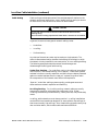
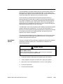
3.3
Inserting the Module into the Base
Before using the module, you should decide whether you want to protect it
by “keying” the module’s position in the I/O base. As shown in Figure 3-1,
keying is accomplished by placing the three keys provided in the right-hand
slot of the two slots occupied by the module so that they fit into the notches
on the module edge card. This prevents another I/O module from being
mistakenly inserted into the slots reserved for a communication module.
!
WARNING
Do not insert or remove the NIM (or keys) while power is applied to the base,
since doing this may cause personal injury, alter controller memory, cause a
controller fatal error, or damage the module.
Until you disconnect power to the I/O base, hazardous voltages are present. Inserting or
removing the NIM before disconnecting power to the base could cause death or serious
injury to personnel, and/or damage to equipment; it could also alter CPU memory, cause a
CPU fatal error, or damage the NIM.
Do not insert or remove the NIM while power is applied to the base.
Figure 3-1 Keying the Series 500 NIM
3-4
Installation
SIMATIC TIWAY I Series 500 NIM User Manual
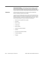
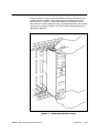
Once the keys are in place, orient the module so that the indicators are on
the top half of the module. Then, carefully push the module into the I/O
base as shown in Figure 3-2. When the module is fully seated in the I/O
base, tabs will hold the module in place. To remove the module, pull the tabs
away from the module and take it out of the I/O base, being careful not to
damage the edgecard.
Figure 3-2 Installing the NIM in the I/O Base
SIMATIC TIWAY I Series 500 NIM User Manual
Installation
3-5
3.4
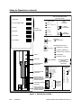
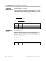
Setting the Dipswitches
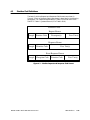
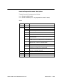
As Figure 3-3 illustrates, there are two blocks of dipswitches on the
Series 500 NIM. The lower block of eight switches is used to select the
NIM’s address on the network. The upper block of ten switches is used to
configure the network communication parameters. Note that the switches
are numbered from bottom to top. When setting up your NIM, use the
configuration data sheet in Appendix C of this manual to record important
configuration information.
NOTE: The configuration and address switch settings are read only once
following a power-up or reset. Be sure to reset the NIM following any
change in dipswitch settings or controller memory reconfiguration.
Selecting the
Network Address
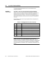
Each NIM on a TIWAY I Network must have a unique address. The range of
valid addresses is 1 to 254 (0000 0001 to 1111 1110 on switches 1–8 of the
lower switch block). Selecting addresses 0 or 255 (0000 0000 or 1111 1111)
on the address select switches will cause the NIM to initialize in a test
mode, and the NIM will fail to operate properly. See Table 3-1 for address
values (bit weight) of each switch and Table 3-2 for addressing examples.
Table 3-1 Network Address Selection
LSB
MSB
3-6
Installation
Open
Closed
SW8
1
0
SW7
2
0
SW6
4
0
SW5
8
0
SW4
16
0
SW3
32
0
SW2
64
0
SW1
128
0
SIMATIC TIWAY I Series 500 NIM User Manual
Table 3-2 Address Examples
Selecting Network
Configuration
Parameters
1
25
203
SW8
Open
Open
Open
SW7
Closed
Closed
Open
SW6
Closed
Closed
Closed
SW5
Closed
Open
Open
SW4
Closed
Open
Closed
SW3
Closed
Closed
Closed
SW2
Closed
Closed
Open
SW1
Closed
Closed
Open
The upper block of ten dipswitches is used in selecting the parameters that
define the network communication environment. There are two physical
media types over which TIWAY I communication can occur: Siemens Local
Line and RS-232-C. Several dipswitches on the configuration switch block
are ignored when operating on the Local Line media. These switches are
noted in the following descriptions.
SIMATIC TIWAY I Series 500 NIM User Manual
Installation
3-7
Setting the Dipswitches (continued)
$
#,
#%
"#
'
#
%
0%%
$
#
"##
0
#%
0%%
,
%0%%
,%0%%
68%"9
%",%''
%)
"
%)
"
##(
#%
""
/"
""
/"
#
#
:8;"%9
)%" ,%
#"#% "
#
#
#"#% "
""#
#%""#<
(""#
#%"'%")'#"#
")'#"#
"%/",$-)"
%"#)%%-&
")"#)%)%#%)
(""#
""#
(")'*#"#
")'#"#
)%),"%#"
)%),"%#"
8 %$,(9
6:
&". ").<6=.":=%
6
2
%'
0(#
%
$
#"
)%))
"-
$
#8%#D
""#%%"
%) "% ")9
"#$%&
$
#"
6
"%#"%#%)
8%)
"9
)%)%#%)
8%'')
"9
"
)%))
"-
$
#'%%#8""#%%"
%) "% ")9
)&-
#+6=.":=%
6=;
<:=;
6=>+?4<:=) 6='())<:=)'
6=.<:=.
6
-(
?
#"
7
")"#
2
)- *6
*?
*7
*2
*61
*A?
*17
-*6?2
"#$%&
"
8));"%
))%"
"
/)
""9
-( #"
")"#
27?6
@@@@
::::
:::6
::6:
::66
:6::
:6:6
:66:
:666
6:::
6::6
6:6:
6:66
66::
66:6
666:
6666
#"
@@@@
*
%#
*
("
*
*
* 66:
* 64:
* A::
* 1::
* 6?::
* ?7::
* 72::
* B1::
* 6B?::
* A27::
* 4C1::
* 664?::
Figure 3-3 NIM Switches and LEDs
3-8
Installation
SIMATIC TIWAY I Series 500 NIM User Manual
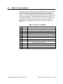
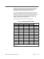
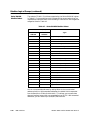
Configuration switches 1 through 4 (on the configuration switch bank)
select the data transmission rate. All devices on the network must be
configured to communicate at the same data rate. The data rates
corresponding to the switch settings are shown in Table 3-3.
For synchronous operation in RS-232-C communication, the rate of data
transmission is established by the modem. When setting switches one
through four, select a data rate which matches that of the modem exactly. If
this is not possible, select the next lower data rate below that of the
modems. Time-out values are determined by dipswitch settings, and
improper settings may cause erratic operation.
Synchronous operation is not valid for local line operation.
Table 3-3 Network Data Rate Switch Settings
Switch Settings
SW1
SW2
SW3
SW4
Data Rate
(BPS)
0
0
0
0
110
0
0
0
1
110
0
0
1
0
110
0
0
1
1
110
0
1
0
0
110
0
1
0
1
150
0
1
1
0
300
0
1
1
1
600
1
0
0
0
1200
1
0
0
1
2400
1
0
1
0
4800
1
0
1
1
9600
1
1
0
0
19,200
1
1
0
1
38,400
1
1
1
0
57,600
1
1
1
1
115,200
0 – closed = on
1 – open = off
SIMATIC TIWAY I Series 500 NIM User Manual
Installation
3-9
Setting the Dipswitches (continued)
Synchronous/Asynchronous Selection. Configuration switch 5 selects
synchronous or asynchronous operation for modems. For synchronous
modem communication, the NIM receives the transmit and receive timing
signals from the modem via transmit signal timing element (DB), and
receive signal timing element (DD). If the modem data rate does not match
a TIWAY data rate exactly, the data rate select switches should be set to a
rate that is the next lower data rate from the modem For example, if a
56,000 bps synchronous modem is used, a data rate of 38,400 bps should be
selected on the NIM.
For asynchronous operation, the transmit and receive timing elements are
generated within the NIM. When using the local line medium, this switch
must be in the asynchronous position (to the right, closed, indicates
asynchronous, to the left, open, is synchronous.)
Full/Half Duplex. Configuration switch 6 selects full or half duplex
operation when communicating over an RS-232-C data link. When half
duplex is selected (switch 6 = 0, closed, or to the right) the NIM waits for the
data carrier detect (DCD) control signal from the modem to go inactive
before activating the request to send (RTS) control signal. If full duplex
operation is selected, the timing relationship between DCD and RTS will be
ignored. When the local line communication media is used, this switch is
ignored since no externally supplied communication control signals are
supplied.
X.25/HDLC. Configuration switch 7 selects the communication protocol.
The HDLC protocol is activated when the switch is set to 0. The X.25
protocol is only activated when this switch is set to 1. The X.25 protocol is
not used with the TIWAY I or UNILINK Host Adapter, although it is an
option when communicating with any host supporting this protocol. For a
more detailed description of these protocols, see the SIMATIC TIWAY I
Systems Manual (TIWAY–8101).
NRZ/NRZI. Configuration switch 8 selects the method of data encoding
used on the physical communication medium. The NRZI method of data
encoding provides a mechanism for the proper decoding of received data in
an asynchronous communication environment. In fact, NRZ encoding will
not work satisfactorily except in the case of synchronous RS-232-C
communication. When using Local Line, or asynchronous RS-232-C , NRZI
encoding must be used. Either type of encoding may be used with
synchronous RS-232-C communication.
3-10
Installation
SIMATIC TIWAY I Series 500 NIM User Manual
Lockout/Enable. Configuration switch 9 enables the P/C to “lockout” the
NIM during time-critical operations. This function is not needed normally.
During lockout, the NIM will not communicate with the P/C. The actual
mechanism is as follows:
1.
The P/C “sees” the NIM as an 8 channel discrete output module on the
I/O portion of the scan.
2.
If the P/C is to “lockout” the NIM during a time critical scan, it can set
the image register address that corresponds to the 8th output of the
module. If switch 9 of the NIM is set to one (to the left with module
installed) the NIM will not communicate with the P/C as long as the
8th output is turned on. To compute the address (A) of the lockout bit
within the P/C’s I/O range, use the following equation:
A ={64 * (B – 1) + [(S – 1) *8]+ 8}
where:
B — base number – 8 module base (1 based, no base #0)
S — I/O module slot number in base (1 based, no slot #0)
NOTE: This is not necessarily true for 520C and 530C controllers with high
density I/O configurations. Consult 520C/530C Hardware Reference Guide
(530–8108) for additional information on high density I/O configurations.
3.
In your Relay Ladder Logic (RLL) program, re-enable NIM to controller
communication by turning the output off after the controller is able to
resume communication with the NIM.
Transmit Delay or Key Delay. Configuration switch 10 provides a delay
of 500 msec following the receipt of Clear to Send (CTS) from a modem. This
delay may be required in radio modem installations to permit the
transmitter to reach full power before transmitting data. This delay is
activated when the key delay switch is set to 1 (positioned to the left).
Other Switches
There are three switches which are located above the Dipswitch banks and
are labeled “Reset” “Self Test” and “Local/Remote”. (Also, some older NIMs
have Local Line bias select switches.) Their functions are described in the
following paragraphs.
Reset. This switch is a momentary contact switch which initializes the
NIM and initiates the power-up self-test. This switch causes all indicators to
be on for approximately 1 second. Then all indicators, with the exception of
the TEST indicator, are extinguished for approximately 5 seconds. During
this time, the NIM runs a series of diagnostic tests to verify the hardware
components of the NIM.
SIMATIC TIWAY I Series 500 NIM User Manual
Installation
3-11
Setting the Dipswitches (continued)
A successful completion of these tests will leave only the NIM GOOD and
PC/NIM COMM GOOD indicators on. If the TEST LED remains on, run the
User Initiated Self-Test to determine the source of the error.
The reset switch should always be pressed after you change the
configuration or address selection dipswitches. If a 560/565 is connected to
the NIM, you should reset the NIM whenever you reconfigure the controller.
This can be done by pressing the NIM reset switch, or by sending a
Secondary Disconnect command from the host (which causes a reset to
occur), followed by a Secondary Connect command.
Test. This switch will cause a series of user initiated diagnostic tests to be
executed IF the local/remote switch is in the local position. It is important to
remember to disconnect all communication cables and to install loopback
connectors on any RS-232-C communication ports before running these
diagnostics.
3-12
Installation
SIMATIC TIWAY I Series 500 NIM User Manual
Local/Remote. When set to remote, this two-position switch enables the
NIM to perform write operations to controller memory. In the local position,
the NIM cannot write to the controller. In either position, the NIM can
monitor P/C memory and mode of operation. The Local Mode will be
indicated (after the NIM is brought into the online state) by a flashing
Online LED indicator. The Remote Mode will be indicated by a continuously
illuminated online indicator.
Local Line Bias. For earlier NIMs supplied with Local Line media
interfaces, a toggle switch is provided which allows selection of bias or no
bias for the Local Line. This switch places a 100 millivolt potential between
each of the two active conductors in the cable. The Local Line must be
biased to prevent undesired oscillations at the receivers connected to the
line. Bias should be applied only by two units (one at each end of the cable)
in the network.
SIMATIC TIWAY I Series 500 NIM User Manual
Installation
3-13
3.5
Series 500 NIM Self Tests
The three levels of Series 500 NIM self tests available in the NIM are
described in the following paragraphs. They are:
Power-up Self-Test
•
Power-Up Self-Test
•
Run-Time Self-Test
•
User-Initiated Self-Test
The Series 500 executes a Power Up Self-Test in the following cases:
•
Immediately following the application of +5VDC from the I/O base
(power-up) as part of its initialization
•
Any time the Reset switch is pressed (See Figure 3-3)
•
Following a Disconnect Secondary command from the host
The Power-Up Self-Test exercises the processor, performs a test of on-board
RAM and ROM, and performs an internal loopback test of the
communication ports. At the start of execution, all NIM indicators (LEDs)
are turned on for approximately 1 second, then all except the Test Mode
indicator are turned off for approximately 5 seconds.
If the Power-Up Self-Test is successful, the NIM GOOD LED will be on, and
an attempt to establish communication with a Series 500 controller will be
made. If this is successful, the PC/NIM COMM GOOD LED will illuminate
and the NIM is ready for normal network operation.
Failure of the Power-Up Self-Test will cause the Test Mode LED to remain
on, and the NIM will not respond to any commmunications attempts.
If the Series 500 controller does not respond, the PC/NIM COMM GOOD
LED will remain extinguished, and the NIM will issue an Exception
Response with Error Code 1A (communication not established with attached
device) to any host computer initiating a controller interactive command to
this NIM.
Run-Time Self-Test
3-14
Installation
The Series 500 NIM monitors itself continuously during normal operation,
as follows:
•
The Operating System continuously performs a ROM integrity test as a
background operation.
•
The NIM periodically verifies that it is capable of communicating with
the Series 500 Sequencer.
•
A Watchdog Timer circuit in the NIM helps to guard against software
lockup.
SIMATIC TIWAY I Series 500 NIM User Manual
Failures detected in the ROM integrity test will cause the NIM GOOD LED
to extinguish, and force the NIM into a failed state. In this condition the
NIM goes to the Logically Disconnected State (LDS) and will always issue a
Disconnect Mode (DM) response to any commands received.
Once the NIM has reached the Normal Operating Mode and fails to
communicate with the controller, it reports this to the host computer with
an Exception Response. Error Code 0A (attached device failed to respond)
will be sent, and the PC/NIM COMM GOOD LED will be extinguished. If
communication is re-established, the NIM will return to Normal Mode and
the PC/NIM COMM GOOD LED will illuminate.
The Watchdog Timer circuit provides an extra measure of protection against
network lockup due to a failed NIM. This circuit will force a Reset if a
failure occurs that prevents the operating software from executing normally.
All indicators on the NIM will be extinguished, and the NIM will not
respond to any network commands.
The communication boards include a “jabberstop circuit” which will disable
the transmitter after 4096 state transitions on the line. This prevents a
network lockup should the NIM fail.
User-Initiated
Self-Test
The User-Initiated Self-Test performs a complete test of the NIM hardware,
including the communication ports. Test execution is detailed in the
following paragraphs.
!
CAUTION
Since this test includes the communication ports, be sure to disconnect the NIM
from the TIWAY I network.
Failure to disconnect the NIM from the TIWAY I network could cause unpredictable
process operation during the user-initiated self-test.
1.
Disconnect network cables from both network ports of the NIM.
2.
Install loopback connectors on the RS-232-C port(s) of the NIM.
3.
Make certain the Local/Remote switch is in the “Local” position.
4.
Press the reset switch.
5.
Press the self-test switch.
SIMATIC TIWAY I Series 500 NIM User Manual
Installation
3-15
Series 500 NIM Self Tests (continued)
Start of execution of the User-Initiated Self-Test will be signaled by the
illumination of the Test Mode LED, with all other LED indicators being
extinguished. Then, after approximately ten seconds, all LED indicators will
flash on and off for approximately two seconds. On completion of the test,
the Test LED will flash at a 2 HZ rate.
A PASS condition will be indicated by the following LED indicators
illuminating:
1.
NIM GOOD
2.
PC/NIM COMM GOOD
3.
RECEIVE
4.
TRANSMIT
5.
TEST (flashing)
FAILURE conditions will be indicated by the following:
1.
If the NIM GOOD LED indicator is extinguished, then a failure was
detected which is internal to the NIM.
2.
If the PC/NIM COMM GOOD LED indicator is extinguished, then a
problem was found in attempting to communicate with a Series 500
controller.
3.
If the RECEIVE LED indicator is extinguished, a failure was detected
on the top network port (Port A). This could be due to:
4.
•
A bad media interface
•
A missing loopback connector (RS-232-C ports only)
If the TRANSMIT LED indicator is extinguished, a failure was
detected on the bottom port (Port B). This could also be due to:
•
A bad media interface
•
A missing loopback connector (RS-232-C ports only)
Following successful execution of the Self-Test, the network cable(s) should
be connected to the NIM, the NIM Reset button should be pressed and the
local/remote switch should be returned to the correct setting (for your
situation). This will reinitialize the NIM, and it will return to normal
operation.
3-16
Installation
SIMATIC TIWAY I Series 500 NIM User Manual
3.6
Module Login Verification
After the NIM has been installed and configured, you should verify that the
NIM is logged into the controller I/O map. This is the first thing you should
do if the PC/NIM Comm Good LED is not on.
Connect a programming device to the controller to verify controller-module
communication.
To do this in a 520/530 P/C system with a VPU200–3102, enter AUX 43,
which checks all I/O points on a particular base. If you have a 520/530
system with a VPU200–3104, press F3 and use the CONFIO function.
If you have a 520/530C or 560/65 controller system with a VPU200–3104,
press F3 for the CONFIO function, then F2 for SHOW, and then F5 for
READ BASE. This sequence allows you to check all I/O points on the base
that the NIM is installed in.
Once you have entered the appropriate command, the controller will
respond with a chart listing all slots on the base and the inputs or outputs
associated with each slot. If a row on the chart is blank, then the
corresponding base slot does not contain a module.
To verify the installation, look in the chart for the slot number
corresponding to the right-most slot of the two slots occupied by the module.
If an “S” or “SF” (special function) and word memory locations appear on
this line, the module is registered in the controller memory and you can
proceed with the usual operations. If the line is blank or erroneous, you
should check the NIM to be sure it is firmly seated in the slots and enter the
appropriate command again. If you still cannot verify the installation, you
should contact your local distributor or the Siemens Technical Services
Group at 423–461–2501 for further assistance.
SIMATIC TIWAY I Series 500 NIM User Manual
Installation
3-17
3.7
Connecting the Network Cables
Network cabling should already be in place before NIM installation is
begun. If you need information concerning network cabling, see the
SIMATIC TIWAY I Systems Manual (TIWAY–8101).
There are two communication ports on the Series 500 NIM, one on the top of
the module (Port A) and one on the bottom (Port B). Depending on the
model you have, these ports accept either an RS-232-C or Local Line
connection. Plug the network interface cables into one of these two ports.
For media redundancy, both ports are used.
3-18
Installation
SIMATIC TIWAY I Series 500 NIM User Manual
Chapter 4
NIM Primitives
4.1
TIWAY I Primitives . . . . . . . . . . . . . . . . . . . . . . . . . . . . . . . . . . . . . . . . . . . . . . . . . . . . . . . . . . . . . . . .
4-2
4.2
Primitive Functions . . . . . . . . . . . . . . . . . . . . . . . . . . . . . . . . . . . . . . . . . . . . . . . . . . . . . . . . . . . . . .
4-3
4.3
Primitive Structure and Operation . . . . . . . . . . . . . . . . . . . . . . . . . . . . . . . . . . . . . . . . . . . . . . . .
4-4
Primitive Operation and Exceptions . . . . . . . . . . . . . . . . . . . . . . . . . . . . . . . . . . . . . . . . . . . . . .
Normal Operation Procedures . . . . . . . . . . . . . . . . . . . . . . . . . . . . . . . . . . . . . . . . . . . . . . . . . . .
Exception Procedures . . . . . . . . . . . . . . . . . . . . . . . . . . . . . . . . . . . . . . . . . . . . . . . . . . . . . . . . . . .
Program Transfer Procedures . . . . . . . . . . . . . . . . . . . . . . . . . . . . . . . . . . . . . . . . . . . . . . . . . . . .
4-6
4-6
4-6
4-7
Primitive Logical Groups . . . . . . . . . . . . . . . . . . . . . . . . . . . . . . . . . . . . . . . . . . . . . . . . . . . . . . . . .
4-9
Series 500 NIM Primitive Subset . . . . . . . . . . . . . . . . . . . . . . . . . . . . . . . . . . . . . . . . . . . . . . . . . . .
4-10
Primitive Field Definitions . . . . . . . . . . . . . . . . . . . . . . . . . . . . . . . . . . . . . . . . . . . . . . . . . . . . . . . .
4-11
Primitive Field Symbols . . . . . . . . . . . . . . . . . . . . . . . . . . . . . . . . . . . . . . . . . . . . . . . . . . . . . . . . . . .
Length Field – LLLL . . . . . . . . . . . . . . . . . . . . . . . . . . . . . . . . . . . . . . . . . . . . . . . . . . . . . . . . . . . . . .
Primitive Code Field – PP . . . . . . . . . . . . . . . . . . . . . . . . . . . . . . . . . . . . . . . . . . . . . . . . . . . . . . . .
Attached Device Status – HH . . . . . . . . . . . . . . . . . . . . . . . . . . . . . . . . . . . . . . . . . . . . . . . . . . . .
Descriptor Field . . . . . . . . . . . . . . . . . . . . . . . . . . . . . . . . . . . . . . . . . . . . . . . . . . . . . . . . . . . . . . . . .
Basic Data Unit – DDDD . . . . . . . . . . . . . . . . . . . . . . . . . . . . . . . . . . . . . . . . . . . . . . . . . . . . . . . . .
4-12
4-12
4-12
4-12
4-13
4-13
4.6
Data Element Types and Formats . . . . . . . . . . . . . . . . . . . . . . . . . . . . . . . . . . . . . . . . . . . . . . . .
4-14
4.7
Data Element Address Ranges . . . . . . . . . . . . . . . . . . . . . . . . . . . . . . . . . . . . . . . . . . . . . . . . . . .
4-24
4.8
Data Field Length Restrictions . . . . . . . . . . . . . . . . . . . . . . . . . . . . . . . . . . . . . . . . . . . . . . . . . . . .
4-26
4.9
Series 500 NIM Primitive Descriptions . . . . . . . . . . . . . . . . . . . . . . . . . . . . . . . . . . . . . . . . . . . . .
4-28
Exception Primitive – Code 00 . . . . . . . . . . . . . . . . . . . . . . . . . . . . . . . . . . . . . . . . . . . . . . . . . . .
Native Primitive – Code 01 . . . . . . . . . . . . . . . . . . . . . . . . . . . . . . . . . . . . . . . . . . . . . . . . . . . . . .
Status Primitive – Code 02 . . . . . . . . . . . . . . . . . . . . . . . . . . . . . . . . . . . . . . . . . . . . . . . . . . . . . . .
Configuration Primitive – Code 03 . . . . . . . . . . . . . . . . . . . . . . . . . . . . . . . . . . . . . . . . . . . . . . .
Primitive Format Configuration – Code 04 . . . . . . . . . . . . . . . . . . . . . . . . . . . . . . . . . . . . . . . .
Packed Native Primitive – Code 05 . . . . . . . . . . . . . . . . . . . . . . . . . . . . . . . . . . . . . . . . . . . . . .
Reset Secondary Device Mode – Code 06 . . . . . . . . . . . . . . . . . . . . . . . . . . . . . . . . . . . . . . .
Segment Definition – Code 07 . . . . . . . . . . . . . . . . . . . . . . . . . . . . . . . . . . . . . . . . . . . . . . . . . . .
Change State Primitive – Code 10 . . . . . . . . . . . . . . . . . . . . . . . . . . . . . . . . . . . . . . . . . . . . . . .
Read Block Primitive – Code 20 . . . . . . . . . . . . . . . . . . . . . . . . . . . . . . . . . . . . . . . . . . . . . . . . . .
Read Random Block Primitive – Code 21 . . . . . . . . . . . . . . . . . . . . . . . . . . . . . . . . . . . . . . . . .
Write Block Primitive – Code 30 . . . . . . . . . . . . . . . . . . . . . . . . . . . . . . . . . . . . . . . . . . . . . . . . . .
Write Random Block Primitive – Code 31 . . . . . . . . . . . . . . . . . . . . . . . . . . . . . . . . . . . . . . . . .
Block Data Acquisition Primitive Codes 50, 51, and 52 . . . . . . . . . . . . . . . . . . . . . . . . . . . . .
Record Data Acquisition Primitive Codes 55, 56, and 57 . . . . . . . . . . . . . . . . . . . . . . . . . . .
Program Upload & Download Primitive Codes 58 and 59 . . . . . . . . . . . . . . . . . . . . . . . . . .
Summary of Primitives . . . . . . . . . . . . . . . . . . . . . . . . . . . . . . . . . . . . . . . . . . . . . . . . . . . . . . . . . . .
4-28
4-30
4-31
4-32
4-33
4-34
4-34
4-35
4-36
4-37
4-38
4-39
4-39
4-40
4-44
4-47
4-58
4.4
4.5
SIMATIC TIWAY I Series 500 NIM User Manual
NIM Primitives
4-1
4.1
TIWAY I Primitives
Primitives are high-level commands that allow a user to access like data
types in all different Secondaries in the same manner. For example, a
Primary can access image register memory in a NIM-equipped 520, 530,
5TI, and PM550 controller with the same command. The purpose of the
Primitives is to remove as many differences as possible between the
controllers, so that applications programs at the Primary level may treat all
TIWAY I Secondaries in the same manner.
Primitives provide the following benefits.
4-2
NIM Primitives
•
Primitives reduce the amount of host computer software needed to
acquire data from the Secondaries.
•
Primitives provide a standard communication protocol that allow you to
communicate with different types of secondaries and attached devices
without custom software routines.
•
Primitives allow more efficient use of the available network bandwidth
by increasing the amount of data that is available in a single message.
For example, with a single programming peripheral Task Code, you
might be able to access no more than 15 words of data. With some
Primitives, up to 134 words can be accessed.
•
Primitives reduce total system loading. This is possible because the
NIMs can memorize data locations that are repeatedly accessed. Block
and Record Gather Primitives make it possible to access a block of data
previously defined and stored in the NIM.
SIMATIC TIWAY I Series 500 NIM User Manual
4.2
Primitive Functions
Primitives serve as the command structure that a TIWAY I Primary uses to
access (read or write) information in a TIWAY I Secondary. The Primitives
defined in the following paragraphs serve these basic functional needs:
•
To access and retrieve data
•
To ascertain the status and configuration of attached devices
•
To perform control operations on the attached device
SIMATIC TIWAY I Series 500 NIM User Manual
NIM Primitives
4-3
4.3
Primitive Structure and Operation
A Primitive consists of multiple fields that specify the Primitive’s length and
function, type and location of data to be accessed, and data to be
transferred. In TIWAY I, a Primitive forms the information field of an
HDLC Information frame (I) or Unnumbered Information frame (UI) if
HDLC operation is selected. If X.25 operation is selected, the Primitive is
contained in the User Data field of an X.25 Data Packet.
!
WARNING
When you write to memory, you may be directly affecting the process which is
under control by the programmable controller.
Unexpected alterations to process operation could cause death or serious
injury to personnel and/or damage to equipment.
Before you make changes in memory, be certain that the changes which result
in the controlled process will not endanger any personnel or equipment.
4-4
NIM Primitives
SIMATIC TIWAY I Series 500 NIM User Manual
Figure 4-1 illustrates the basic Primitive structure when HDLC operation is
selected. There is a Request Format and a Response Format, as shown. The
binary weight of the fields is detailed in Figure 4-2. All field lengths are
multiples of 8 bits, which allows for octet testing of data link frames at the
data link/media access control layer.
)
'(
'
)-
:
2
61
?7
*?7
*2
' '
'
!'
E'
)3
!
89
(89
'
)3 ,"
(89
Figure 4-1 Basic Primitive Structure
The maximum length of the Information field is 273 bytes for the Series 500
NIM. In the Request format, the 273 bytes include the Length, Primitive
code, Descriptor, and Data Unit fields. In the Response format, the 273
bytes include the Length, Primitive Code/Error, Secondary Status, and Data
Unit fields. In both formats, the 273 bytes exclude the protocol control
fields. Other devices connected to TIWAY I may support Information Field
lengths in excess of 273 bytes. The actual length support is dependent on
device type and must be ascertained with the Format Configuration
Primitive 04.
SIMATIC TIWAY I Series 500 NIM User Manual
NIM Primitives
4-5
Primitive Structure and Operation (continued)
'#-
'
"
)
)-
-
Figure 4-2 Binary Weight of the Fields
Primitive Operation
and Exceptions
Normal Primitive operation consists of a request and response sequence
without exceptions. Exceptions are errors found in the interpretation or
execution of a Primitive.
Normal Operation
Procedures
The normal operation of a Primitive is for the initiating (Host) station to
form a request Primitive and address it to a Secondary on the network. If
the request Primitive contains allowable data element types and data
element location ranges, a legal Primitive Code for the specific device–type
addressed, and the correct Length Field value, then the device addressed
will return a response Primitive of the proper format.
Exception
Procedures
An exception procedure is used when the addressed device finds fault with:
•
The value of the Length field
•
A Primitive format
•
A data element type
•
The execution of a Primitive
If a fault is found with the Length field, Primitive format, data element type
or in the execution of the Primitive, the exception reason is returned with
the Exception Primitive, which is Primitive Code 00. The procedure taken
depends on the Primitive used. There are two classes of procedures used for
handling exceptions:
4-6
NIM Primitives
1.
Procedures which are associated with reading data elements
2.
Procedures which are associated with writing data elements
SIMATIC TIWAY I Series 500 NIM User Manual
Exception when Reading. The device performing the Primitive operation
aborts execution of a Primitive when an exception condition is encountered,
and returns the reason for the exception. The device requesting the
Primitive should evaluate returned message, take appropriate corrective
measures, and attempt retransmission of the Primitive.
Exceptions when Writing. Exceptions concerning Primitive format,
contents, or device state when writing will abort the entire Primitive. Some
exceptions indicate an error during execution of the Primitive. In this case,
the data elements specified in the Primitive may or may not have been
modified. Therefore, when the exception condition is returned to the sender,
all data element locations specified by the failed Primitive should be
re-written. The station sending the Primitive should examine the exception
reason, take appropriate corrective measures, and try to send the Primitive
again.
Program Transfer
Procedures
The data needed to archive or restore the operating environment of a device
will vary from one device to the next. Relevant data may be Relay Ladder
Logic (RLL) programs and associated configuration parameters, controller
process control loop information, or a machine configuration list from a
UNILINK Secondary Adapter. To release the network host from having to
record the various and diverse data types associated with this information,
the program upload/download concept was developed. The program
upload/download Primitives allow the network host to archive or restore
operating environments from different types of network secondaries in a
standard (or generic) fashion.
To keep the transfer as device independent as possible, several unique
procedures have been defined to allow easier resource management:
•
Initialize Upload/Initialize Download — places the attached device
(controller, robot, CNC machine, etc.) in a safe, non-operational state,
and defines the types of data to be uploaded or downloaded.
•
Transfer Upload/Download data — transfers all operating environment
data. These transport utilities are managed in a sequential manner to
ensure proper sequencing of data frames.
•
Terminate Upload/Download — terminates all program
upload/download activity and returns the attached device to its original
operating condition (if possible).
Four Primitives have been developed to complete the above tasks. Primitive
07 allows you to query the attached device for the type of program segments
it contains. Primitives 58 and 59 provide data upload and download
capability. Primitive 06 allows you to terminate the program transfer and
return the attached device to its previous state.
SIMATIC TIWAY I Series 500 NIM User Manual
NIM Primitives
4-7
Primitive Structure and Operation (continued)
The upload and download formats will always be identical, i.e., data that is
received from an upload request will be sent unmodified (in the same order
and format) to the attached device during download.
You cannot write data or change the attached device operating mode during
an upload or download request; however, you can continue to read data. If
an attempt is made to write data or change the operating mode, an
exception code will be returned. Also, you cannot initiate another upload or
download request until the previous request is complete. The native and
packed native Primitives are not allowed in upload or download mode if
they contain a write command.
Program transfer procedures are slightly different from normal operations
in that the NIM and the controller must change operating states to
participate in the data transfer. Program upload and download are mutually
exclusive and cannot occur simultaneously. Only one generic load operation
may be executed at any given time.
4-8
NIM Primitives
SIMATIC TIWAY I Series 500 NIM User Manual
4.4
Primitive Logical Groups
All Siemens TIWAY Primitives fall into logical groups according to their
function, as shown in Table 4-1. Each Primitive has a request and a
response format. The device initiating the transaction formats a request
Primitive, and the device answering the request formats a response
Primitive. The TIWAY I Primitive subset is taken from the categories listed
in Table 4-1.
Table 4-1 Logical Primitive Assignment
Primitive Code (HEX)
Function
16-Bit Addressing
Extended Addressing
Exception and Status
00 — 0F
80 — 8F
Control
10 — 1F
90 — 9F
Read
20 — 2F
A0 — AF
Write
30 — 3F
B0 — BF
Program Modification
Aids
40 — 4F
C0 — CF
Data Acquisition
Primitives
50 — 6F
D0 —EF
Undefined
70 — 7E
F0 — FE
Expansion
7F
FF
SIMATIC TIWAY I Series 500 NIM User Manual
NIM Primitives
4-9
Primitive Logical Groups (continued)
Series 500 NIM
Primitive Subset
The subset of TIWAY I Primitives supported by the Series 500 NIM is given
in Table 4-2. Future additions to this subset will be announced as they are
implemented. Note that each of the following Primitives fits into the general
categories listed in Table 4-1.
Table 4-2 Series 500 NIM Primitive Subset
Primitive Code (HEX)
Type
Non-extended
Address
Extended
Address
00
80
Exception reporting
01
81
Native
02
82
Attached device status
03
83
Attached device type/confirmation
04
84
Primitive format configuration
05
85
Packed native
06
86
Reset secondary device mode
07
87
Segment definition
10
90
Change state
20
A0
Read block (single contiguous block)
21
A1
Read random block
30
B0
Write block (single contiguous block)
31
B1
Write random block
50
D0
Define blocks (up to 32 separate blocks)
51
D1
Gather defined blocks
52
D2
Write and gather defined blocks
55
D5
Define records (up to 32 records)
56
D6
Gather defined records
57
D7
Write and gather defined records
58
D8
Program upload
59
D9
Program download
You can use extended addresses by adding 80hex to the non-extended
address primitive. With extended addresses, the AAAA field is expanded
from sixteen bits to 32 bits (AAAAAAAA). This allows you to access data
element locations beyond the non–extended limit of 65,535. With extended
addresses, you can access up to 4,294,967,296 locations.
4-10
NIM Primitives
SIMATIC TIWAY I Series 500 NIM User Manual
4.5
Primitive Field Definitions
The basic Primitive Request and Response field formats are shown in
Figure 4-3. Each of the basic field types shown is described in the following
paragraphs. For a detailed explanation of TIWAY Primitives refer to the
SIMATIC TIWAY I Systems Manual (PPX:TIWAY–8101).
!'
E'
)3 !
89
(89
'
)3
!
(89
"'
)3
"F
!
(89
Figure 4-3 Primitive Request and Response Field Format
SIMATIC TIWAY I Series 500 NIM User Manual
NIM Primitives
4-11
Primitive Field Definitions (continued)
Primitive Field
Symbols
The symbols used in the remainder of this section to denote the different
types of Primitive fields are summarized in Table 4-3.
Table 4-3 Summary of Primitive Field Symbols
Symbol
Description
LLLL
Length field
PP
Primitive code
HH
Attached device status
TT
Data element types
NNNN
Number of data elements
AAAA or AAAA AAAA
Data element location
DDDD
Data unit(s)
XX
Number of user-derfined structures requested
CC
User-defined structure number
EEEE EEEE
User-defined structure mask
YYYY
Application sequence count
RRRR
Host reference number
MMMM
Attached device data segment definition
OOOO
Attached device time-out value
Length Field – LLLL
The Length Field (refer to Figure 4-3) is a 16-bit field that represents the
length (in bytes) of the Primitive, Descriptor(s), and Data Unit field(s). The
Length Field is initialized by the Primary in transmissions to the NIM. It is
also initialized by the NIM in transmissions to the Primary. (Example: the
Length Field for a Primitive 02 request would have a value of 1.)
Primitive Code
Field – PP
The Primitive Code Field (see Figure 4-3) is eight bits long, which allows for
256 unique Primitives. The most significant bit of the primitive field code is
used to designate that the extended addressing mode is in effect. In this
mode, the data element location descriptor is a 32-bit field rather than the
16-bit field associated with non-extended addressing.
The Series 500 NIM currently supports a subset of the Primitives: 00, 01,
02, 03, 04, 05, 06, 07, 10, 20, 21, 30, 31, 50, 51, 52, 55, 56, 57, 58, and 59.
The corresponding extended addressing codes are: 80, 81, 82, 83, 84, 85, 86,
87, 90, A0, A1, B0, B1, D0, D1, D2, D5, D6, D7, D8, and D9 (all values in
hexadecimal). These Primitive Codes are described in detail later in this
chapter.
Attached Device
Status – HH
4-12
NIM Primitives
The attached device status is updated by the NIM every four seconds. The
most recent attached device status is returned in most primitives.
SIMATIC TIWAY I Series 500 NIM User Manual
Descriptor Field
Within the Descriptor Field (see Figure 4-3) are different fields to define the
following: data element types, location or address of a data element, number
of data elements to access, and the status of the attached device. The
Descriptor Field may contain a single descriptor or multiple descriptors as
required by the various Primitives.
Data Element Types — The length of the data element type descriptor field
is eight bits. This field, labelled “TT”, is a code that corresponds to the
different types of data found in the attached device. See Table 4-4 for a list
of data element types.
Current Status of Attached Device — Current status is designated by “HH”.
Number of Data Elements to access — This 16-bit field is designated by
“NNNN”. A value of one is interpreted as one location to be accessed. The
length of a location is determined by the data element type. The number of
locations requested should not exceed the maximum allowed for that device
type (see Table 4-4 and Table 4-5).
Data Element Location — Data element types are accessed by a location
number, designated by “AAAA” or “AAAA AAAA”. In the Series 500 NIM,
the location descriptor is a 16-bit value (32 bits if extended addressing is
used in the primitive code field). The allowable values for the location
number are shown in Table 4-5.
The format of the AAAA field changes for these TT types are:
(1)
TT Type 12 (Drum Count Preset) The format is:
AAAA = DD SS, AAAA AAAA = DDDD SSSS (extended
addressing)
where
(2)
DD = Drum Number
SS = Step Number (1 – 10)
TT types (36–3B, 76–7A) (Ramp Soak) The format is:
AAAA = LL SS or AAAA AAAA = LLLL LL SS (extended
addressing)
where
Basic Data Unit –
DDDD
LL = Loop Number (1 – 40)
SS = Step Number (0 – FF)
The definition of the Basic Data Unit Field is dependent upon the data
element type specified in both the Descriptor Field and the Primitive format
definition. The Basic Data Unit is designated “DDDD” or “DD” in this
manual.
SIMATIC TIWAY I Series 500 NIM User Manual
NIM Primitives
4-13
4.6
Data Element Types and Formats
The data element types (TTs) and their length (in bytes) are defined in
Table 4-4. Figure 4-4 through Figure 4-15 show the format of the data
elements.
Table 4-4 Data Element Types and Formats
TT
Data Element Type
Length
(in bytes)
0
Instruction Memory (L)
2
1
Variable Memory (V)
2
2
Constant Memory (K)
2
3
Discrete Input (X)
1
4
Discrete Output (Y)
1
5
Control Register (CR)
1
6
Discrete Input Packed (X)
1
7
Discrete Output Packed (Y)
1
8
Control Register Packed (CR)
1
9
Word Input (WX)
2
A
Word Output (WY)
2
B
XY Force
1
C
CR Force
1
D
Word Force
3
E
Timer-Counter Preset (TCP)
2
F
Timer-Counter Current (TCC)
2
10
Drum Step Preset (DSP)
1
11
Drum Step Current (DSC)
1
12
Drum Count Preset (DCP)
2
17
Secondary System Status*
4
** 20 or 60
Loop Gain
4
** 21 or 61
Loop Reset
4
** 22 or 62
Loop Rate
4
** 23 or 63
Loop High Alarm
4
** 24 or 64
Loop Low Alarm
4
** 25 or 65
Loop Process Variable
4
* These TT types are read-only data elements.
# This TT type is a write-only data element.
** Format
2x, 3x, and 4x = IBM format
6x, 7x, and 8x = IEEE format
4-14
NIM Primitives
SIMATIC TIWAY I Series 500 NIM User Manual
Table 4-4 Basic Data Unit Format (continued)
TT
Data Element Type
Length
(in bytes)
** 26 or 66
Loop Process Variable High Limit
4
** 27 or 77
Loop Process Variable Low Limit
4
** 28 or 78
Loop Orange Deviation Alarm
4
** 29 or 79
Loop Yellow Deviation Alarm
4
** 2A or 6A
Loop Sample Rate
4
** 2B or 6B
Loop Remote Setpoint
4
** 2C or 6C
Loop Output
4
2D
Loop Status*
2
2E
Loop Control Flags
4
2F
Ramp/Soak Status*
2
**30 or 70
Loop Error*
4
**31 or 71
Loop Bias
4
** 32 or 72
Loop Process Variable High High Alarm
4
** 33 or 73
Loop Process Variable Low Low Alarm
4
** 34 or 74
Loop Rate of Change Alarm
4
# 35
Loop Mode
2
** 36 or 76
Ramp/Soak Step
13
** 37 or 77
Ramp Destination Setpoint
4
**38 or 78
Ramp Rate
4
** 39 or 79
Soak Time
4
**3A or 7A
Soak Deadband
4
3B
Ramp/Soak Event Status Bit
3
**3C or 7C
Analog Alarm P.V. High Alarm
4
** 3D or 7D
Analog Alarm P.V. Low Alarm
4
** 3E or 7E
Analog Alarm Process Variable
4
** 3F or 7F
Analog Alarm P.V. High Limit
4
** 40 or 80
Analog Alarm P.V. Low Limit
4
** 41 or 81
Analog Alarm Orange Deviation Alarm
4
** 42 or 82
Analog Alarm Yellow Deviation Alarm
4
* These TT types are read-only data elements.
# This TT type is a write-only data element.
** Format
2x, 3x, and 4x = IBM format
6x, 7x, and 8x = IEEE format
SIMATIC TIWAY I Series 500 NIM User Manual
NIM Primitives
4-15
Data Element Types and Formats (continued)
Table 4-4 Basic Data Unit Format (continued)
TT
Data Element Type
Length
(in bytes)
** 43 or 83
Analog Alarm Sample Rate
4
** 44 or 84
Analog Alarm Setpoint
4
45
Analog Alarm Variable Flag*
2
46
Analog Alarm Control Flag
4
** 47 or 87
Analog Alarm Error*
4
** 48 or 88
Analog Alarm P.V. High High Alarm
4
** 49 or 89
Analog Alarm P.V. Low Low Alarm
4
** 4A or 8A
Analog Alarm Rate of Change Alarm
4
* These TT types are read-only data elements.
# This TT type is a write-only data element.
** Format
2x, 3x, and 4x = IBM format
6x, 7x, and 8x = IEEE format
NOTE: See Appendix B for a definition of TT 2x, 3x, 4x, 6x, 7x, and 8x
floating point representation.
##=AD7D4= 869
6?A741C2
-):
:
:
:
:
:
:
>
>!-
:%
6%
Figure 4-4 Discrete Data Element Format
4-16
NIM Primitives
SIMATIC TIWAY I Series 500 NIM User Manual
##=1DCD2=869
6?A741C2
-)-
FE+
'+
/- :
6
%
%
3E!3D
3G+
Figure 4-5 Packed Discrete Data Element Format
##=-=$8A9
H
I
!
::
:6
'
(
'
<!''
+D3!3!
+
Figure 4-6 Forced Word Data Element Format
SIMATIC TIWAY I Series 500 NIM User Manual
NIM Primitives
4-17
Data Element Types and Formats (continued)
##=-D=-< D6<D6
-
6
?
.
:
A
7
4
1
C
2
:
:
:
:
:
>
>!
:
6
-
%
%
.!
:
6
'
(
'
)-
Figure 4-7 Forced Discrete and CR Data Element Format
##=6C=8?9J
$K6<
-
)"'0 L&) %
"3633
?+
$K?<
-
"'0 L&) %
=:
"%#"
=6
)%)
-=:,"%#"
=6,)%)
*8:9
J#3
Figure 4-8 Secondary System Status Data Element Format
4-18
NIM Primitives
SIMATIC TIWAY I Series 500 NIM User Manual
'<##=? =)89
)-
-
" ' 0 L
& ) % *)<
D3+
GD
3+
-*)<
D3+
GD3+
*" !<
D3!!+
GD3!!+
*/33<
D3!33
33+
GD3!3333
+
"*/3<
D3!33+
GD3!33+
'*/)<
D3!+
GD3!+
0*/))<
D3!
+
GD3!+
*.-<
D3!3+
GD3!3+
*%-<
D3!3+
GD3!3+
L */3<
D3/
3+
GD3/3
841:,4149+
& */-#<
D3/3
+
GD3/3!
841:,4149+
) *)%!<
D3!*
+
GD3!8
41:,4149+
*<G+
Figure 4-9 Loop Status Data Element Format
SIMATIC TIWAY I Series 500 NIM User Manual
NIM Primitives
4-19
Data Element Types and Formats (continued)
##=?"=)'89
)-
- "'0
L&)%
M#(/$> .;
* /?:5
- * #E/
* 0,)%$
* 0,
0,)%$*)%$
" * !
' * **3
0 * * (
3
* (
!3
L * & * !
) * "E
* "
* ),
% * )
* )
* "F'3+/+
* "F'3
# * 'G**
( * ,3
/ * %
$ * !
> * "!!
.* * 3'3F
36D3+
3:D3
+
Figure 4-10 Loop Control Flag Data Element Format
4-20
NIM Primitives
SIMATIC TIWAY I Series 500 NIM User Manual
##=?'=,89J
)-
- "'0
L&)%
*386=9
-*3+/+86=9
**(G
* * ,F8:*?449
J #3+
Figure 4-11 Ramp/Soak Status Data Element Format
##=A4=)89J
- "'0
L&)
%
=6*0()
:*
-=6*0(#%#
:*
=6*0)%" "
:*
=6*)
:*
"=6*)
:*
'=6*LF,
:*
0*=(8 :9
3D3
()D(#%#
D "+
J#3+
Figure 4-12 Loop Mode Data Element Format
SIMATIC TIWAY I Series 500 NIM User Manual
NIM Primitives
4-21
Data Element Types and Formats (continued)
##=A1=,86AD
"""N##C1
-9
:::&
##
""""
&
*
8:=D6=9
##
*
"!8:7=.D
:4=D9
"!
""""
*
*
*
<3
<3
<33
<3
Figure 4-13 Ramp/Soak Step Data Element Format
##=74=/'869J
-
)-
- "'0
*
"JJ
- *
JJ
*
*
L&)%
!3333
!33
" *
!
' *
!
0 *
!!
*
!!
*
!3
L
*
!
& *
)* *
!
(G
J
JJ#3
3D3+
3GD3+
Figure 4-14 Analog Alarm Variable Flag Data Element Format
4-22
NIM Primitives
SIMATIC TIWAY I Series 500 NIM User Manual
##=71='8?9
)-
- "'0
L&)%
#(/$>.
;
* /?:5
- * #E/
* 0,)%$
* 0*
0,)%$*)%$
" * !
' * **3
0 * * )=:
=6
*> * (G
.* * 6D3+
:D3+
Figure 4-15 Analog Alarm Control Flag Data Element Format
SIMATIC TIWAY I Series 500 NIM User Manual
NIM Primitives
4-23
4.7
Data Element Address Ranges
The maximum data element locations (AAAA field) for each data element
type / controller combination are provided in Table 4-5. All values in the
table are 1-based (first legal value is 1; not zero). Values of zero are not
supported.
4-24
NIM Primitives
SIMATIC TIWAY I Series 500 NIM User Manual
Table 4-5 Data Element Address Ranges
P/C Type
Data Type
520–
1101
530–
1102
530–
1104
530– 520C 520C 530C 530C 530C
1108 –1101 –1102 –1104 –1108 –1112
560–
1101
565–
1101
NOTE
L Instruction
TT = 00
1024
2048
4095
8191
*
1024
2048
4096
8192
12000 8192
8192
B
V Variable
TT = 01
512
1024
1024
2048
512
1024
2048
4096
5120
2048
2048
B
K Constant
TT = 02
0
0
0
0
0
0
0
0
0
0
0
A,B
Discrete I/O
X,Y,X&Y Packed
TT = 3,4,6,7
128
1023
1023
1023
1023
1023
1023
1023
1023
2048
2048
B
Control Register
CR, CR Packed
TT = 5,8
256
511
511
511
255
511
511
511
1023
2048
2048
B
Word I/O
WX, WY
TT = 9,A
128
1023
1023
1023
1023
1023
1023
1023
1023
2048
2048
B
Discrete Force
TT = 0B
128
1023
1023
1023
1023
1023
1023
1023
1023
2048
2048
B
CR Force
TT = 0C
256
511
511
511
255
511
511
511
1023
2048
2048
B
Word Force
TT = 0D
128
1023
1023
1023
1023
1023
1023
1023
1023
2048
2048
B
Timer/Counter
TCC/TCP
TT = E,F
128
255
255
255
60
256
256
256
400
1024
1024
B
Drum Step
DSP, DSC, DCP
TT = 10,11,12
10
30
30
30
15
30
30
30
30
128
128
B,D
System Status
TT = 17
1
1
1
1
1
1
1
1
1
1
1
B
Loop Data
TT = 20–35 and
60–75
0
0
0
0
0
0
0
0
0
0
64
A,B
Ramp/Soak Data
TT = 36–3B
0
0
0
0
0
0
0
0
0
0
255
B,C
Analog Alarm
TT = 3C–4A and
7C–8A
0
0
0
0
0
0
0
0
0
0
128
A,B
Notes:
A) Entry of zero is a non-supported or non-configured Data Type for the P/C.
B) 560 and 565 data sizes are default values for a minimal system configuration. All of these values (except loops, analog
alarms and system status) can be reconfigured.
C) There are 255 ramp/soak steps for each loop in a 565.
D) There are 16 steps for each event drum in a P/C.
*
Read only (L-memory in EPROM only).
SIMATIC TIWAY I Series 500 NIM User Manual
NIM Primitives
4-25
4.8
Data Field Length Restrictions
Table 4-6 and Table 4-7 delineate the maximum length of the data field, in
bytes, for Read and Write Primitives.
Table 4-6 Maximum Read Primitive Byte Length
!+
F
!E+
8$3F
9
?:
?6
46
4?
41
4C
?1B
?12
?14
?14
?12
?12
?1B
?12
?14
?14
?12
?12
!E38##9!E
83!:4D?6D46D4?D41D4C9!
!3E33+
#7*73D#7*4
+
4-26
NIM Primitives
SIMATIC TIWAY I Series 500 NIM User Manual
Table 4-7 Maximum Write Primitive Byte Length
$!
F
3
!
E+
8$3F
9
A:
A6
4?
4C
?1C
?14J
?1A
?14JJ
?14
?1AJ
?16
?1AJJ
Table 4-4 3 3 D Table 4-5 3F!+
J#33E+(3
33
<
<=?C:*84J#9
"F<=?C:*8CJ#9
3<
=F333
!E+
#=3!E+
JJ#33E+(3
3E<
=?11*D3<=3!+
"F<=?17*
SIMATIC TIWAY I Series 500 NIM User Manual
NIM Primitives
4-27
4.9
Series 500 NIM Primitive Descriptions
The following paragraphs describe the NIM Primitives used in the
Series 500 NIM. Refer to Table 4-2 for a complete list of the Primitives
supported.
Exception Primitive
– Code 00
Availability: Releases 1.1, 2.1, 2.2, and 3.0
Primitive 00 allows you to obtain an error status from a Secondary. For
example, if a Primary tries to read variable memory at location 0000 in a
Series 500 NIM, a Primitive 00 response would indicate that the memory
address was out of range with an exception field of 0002.
Request: There is no request defined for this Primitive.
Response: LLLL 00 PP DDDD (TT is optional)
Symbol
Value
PP
DDDD
4-28
NIM Primitives
Definition
Request primitive code that contains the exception
0
Primative code is not implemented.
1
Data type (specified by TT) is not defined on the
attached device.
2
Data element location (specified by TT) is out of range.
3
Primitive has excess data unit bytes.
4
Primitive has insufficient data unit bytes.
5
The number of information bytes received does not
match the number of bytes specified in the field
length.
6
Device is in wrong mode for primitive execution.
7
User program in the attached device has disabled
communication to the Series 500 NIM via the lock-out
bit.
A
Attached device fails to respond
E
Primitive not valid for the specified data type (TT).
10
The number of locations requested exceeds the
maximum allowed.
11
The number assigned to a data acquisition block or
record is not within the supported block or record
range.
12
The block or record number requested has not been
defined.
13
The number of data bytes in the requested blocks or
records exceeds the maximum number of bytes
allowed by the primitive.
15
Primitive not allowed while device is in local mode.
SIMATIC TIWAY I Series 500 NIM User Manual
Symbol
Value
DDDD
16
TT not programmed in attached device.
17
The attached device did not respond properly.
19
The resulting data element location formed by the
starting address, plus the number of data elements to
access is out of range specified by TT.
1A
Communication has not been established with the
atttached device.
1B
The store and forward buffer is full and the store and
forward message was discarded.
1C
Data element field (specified by TT) is improperly
formatted.
1D
The number of locations to access is zero (NNNN = 0).
23
The number of data blocks defined in a data
acquisition record exceeds the maximum supported.
24
An illegal IEEE floating point value (an IEEE NaN,
Not-a-Number) exists in a primitive write request.
25
The address value exceeds the structure format in the
request. Use extended structure format.
29
Store and forward mechanism is not allowed in this
primitive.
2B
The write request was refused, the device is in the
program upload or download mode.
2C
The upload or download command field, “CC” is not
supported.
2D
The upload or download primitive request was
refused. The attached device is currently in progress
with an upload or download.
2E
The upload request segments or programs are not
supported or the segments were not defined.
80DD
Exception generated in the attached device is not
identified.
TT
SIMATIC TIWAY I Series 500 NIM User Manual
Definition
Optional element data type.
NIM Primitives
4-29
Series 500 NIM Primitive Descriptions (continued)
Native Primitive –
Code 01
Availability: Releases 1.1, 2.1, 2.2 and 3.0
The native Primitive 01 allows access to an attached device by using a Task
Code which is unique to the specific device addressed. By using 01, a
programmer can embed a controller-unique Task Code and can access
anything in controller memory, for example, that a VPU can access.
Request: LLLL 01 DDDD, where DDDD is defined by the task codes of the
device being accessed.
Response: LLLL 01 HH DDDD, where DDDD is defined by the task codes of
the device type accessed.
Symbol
HH
DDDD
4-30
NIM Primitives
Value
Definition
Operational status
Defined by the type of device being accessed.
SIMATIC TIWAY I Series 500 NIM User Manual
Status Primitive –
Code 02
Availability: Releases 1.1, 2.1, 2.2, and 3.0
Primitive 02 is the machine status Primitive. It reports the current
operational state of the attached device and NIM in a common format for all
types of attached devices. The NIM gets a status update from the attached
device every 4 seconds (and immediately when an 02 Primitive is issued).
Request: LLLL 02
Response: LLLL 02 HH EE FF, where:
Symbol
Value
HH
Attached device operational status (mode)
00
Operational and performing instruction data type and
loop execution. (RUN)
01
Operational and performing instruction data type and
loop execution with a non-fatal error detected. (RUN
with non-fatal error)
02
Operational and not performing instruction data type
execution with loop execution. (PROGRAM)
03
Operational and not performing instruction data type
or loop execution. (PROGRAM)
04
Operational and not performing instruction data type
execution with loop execution and a non-fatal error is
detected. (PROGRAM with non-fatal error)
05
Operational and not performing instruction and data
type or loop execution and a non-fatal error is
detected. (PROGRAM with non-fatal error)
80
Not operational due to a fatal error condition.
EE
Attached device auxiliary power source status
00
Auxiliary power source good
01
Auxiliary power source status not available
80
Auxiliary power source not good
FF
SIMATIC TIWAY I Series 500 NIM User Manual
Definition
NIM operational status
00
Operational
01
Channel A is not functional
02
Channel B is not functional
NIM Primitives
4-31
Series 500 NIM Primitive Descriptions (continued)
Configuration
Primitive – Code 03
Availability: Releases 1.1, 2.1, 2.2, and 3.0
Primitive 03 allows the Primary to identify the types of devices that exist on
the network. For example, an 03 response from a 520 P/C would be different
from a response from a 5TI P/C.
Request: LLLL 03
Response: LLLL 03 HH DDDD EEEE FFFF GGGG IIII JJJJ KKKK KKKK
Symbol
Value
HH
Attached device operational status
DDDD
4-32
NIM Primitives
Definition
Device type
0000
5TI
0020
520
002C
520C
0030
530
003C
530C
0040
540
0050
550
0060
560
0065
565
007E
UNILINK Host Adapter
0080
PM550
0081
PM551
0100
UNILINK Secondary Adapter
0200
IT–111/121 Intelligent Tank Transmitter
0204
IT–150 Hydrostatic Tank Transmitter
0208
IT–160 Micro Remote Control Unit
EEEE
hex
Instruction data type memory size
FFFF
hex
Variable data type memory size
GGGG
hex
Constant data type memory size
IIII
hex
Local input/output memory size
JJJJ
hex
Global input/output memory size
KKKK
hex
Total memory size (excluding input and output)
SIMATIC TIWAY I Series 500 NIM User Manual
Primitive Format
Configuration –
Code 04
Availability: Releases 1.1, and 2.1, 2.2, and 3.0
Primitive 04 is the format Primitive that allows you to ascertain the
maximum length of the Primitive acceptable to the Network Interface
Module. The buffer length is returned in number of bytes.
Request: LLLL 04
Response: LLLL 04 NNNN MM EE FF GG BB ... BB
89
Symbol
Value
NNNN
Definition
Primitive descriptor(s) and data unit(s) field length
supported, in bytes (270 bytes is returned)
MM
Number of Data Acquisition Blocks supported by the
NIM (Primitives 50, 51, 52) (32 is already returned)
EE
Number of Data Acquisition Records supported by the
NIM (Primitives 55, 56, 57). Used with releases 2.1,
2.2, and 3.0 (32 is returned)
FF
Number of Data Type Definitions supported in each
defined record in the NIM (Primitives 55, 56, 57). Used
with releases 2.1, 2.2, and 3.0 (32 is returned)
GG
Floating Point Formats supported in the NIM. Used
with releases 2.0 and 3.0
BB
SIMATIC TIWAY I Series 500 NIM User Manual
00
No floating point support
01
IBM Excess 64 format support
02
IEEE Standard 754 format support
03
Both IBM and IEEE format support
Primitive support bit mask for the NIM. The first bit
represents Primitive 0. Primitive values increment by
1 for each bit position. A one in a bit position indicates
that the corresponding Primitive is supported. For
example, if bit 3 is set to 1, then Primitive 03 is
supported. For example, if bit 3 is set to 1, then
Primitive 03 is supported.
NIM Primitives
4-33
Series 500 NIM Primitive Descriptions (continued)
Packed Native
Primitive – Code 05
Availability: Releases 2.1, 2.2, and 3.0
Primitive 05 allows one or more device task codes to be executed. Execution
is aborted and an exception response returned if an exception occurs during
processing. If an exception occurs during execution of any native task code,
the error results are returned in the packed native response in the same
position as in a normal response. Execution continues in this situation.
Native task codes concerning “store” and “forward” are not supported.
Request: LLLL 05 CC DD ... DD
89
Response: LLLL 05 HH CC DD ... DD
89
Symbol
Reset Secondary
Device Mode –
Code 06
Value
Definition
HH
Attached device operational status
CC
Number of bytes in the task code field DD
DD
Task codes of the device type being accessed
Availability: Release 3.0
Primitive 06 returns the Secondary to its initial “ready” stated for program
upload/download operations (Primitives 58 and 59). Resetting the
secondary may affect the status of the attached device in some cases
(depending on the type of attached device and the relationship between the
attached device and Secondary).
Request: LLLL 06
Response: LLLL 06 HH
Symbol
HH
4-34
NIM Primitives
Value
Definition
Attached device operational status
SIMATIC TIWAY I Series 500 NIM User Manual
Segment Definition
– Code 07
Availability: Release 3.0
Primitive 07, used with the Program Upload and Download Primitives (58
and 59), obtains the attached device segment definition as an ASCII string.
The definitions contain the segment number they represent and relate
one-to-one with the MMMM descriptor (starting at bit P) defined in
Primitive 58. Primarily, this request determines a starting point from which
to obtain the definitions. This allows you to obtain ASCII strings that would
otherwise exceed the maximum returnable length.
Request: LLLL 07 VV SS
Symbol
Value
VV
Definition
Segment type
00
Generic segment definition
01
Secondary device segment definition
02
Program names definition
SS
Starting segment number (or program name) to be
returned
Response: LLLL 07 HH VV KK SS CC DD ... DD
(repeated)
Symbol
Value
Definition
HH
Attached device operational status
VV
Segment type
00
Generic segment definition
01
Secondary device segment definition
02
Program name definition
KK
Total number of segment or program definitions
SS
Segment number definition being returned
CC
Number of bytes in the ASCII DD field
DD
ASCII segment definition defined by the attahced
device. The first two DD descriptors contain the
MMMM (Bit Map) field for the program.
SIMATIC TIWAY I Series 500 NIM User Manual
NIM Primitives
4-35
Series 500 NIM Primitive Descriptions (continued)
Change State
Primitive – Code 10
Availability: Releases 1.1, 2.1, 2.2, and 3.0
This Primitive allows you to change the operational state of TIWAY I
Secondaries. For example, you may enter the Run or Program modes with
this Primitive.
Request: LLLL 10 DD, where
Symbol
Value
DD
Definition
Operational Status
00
Enter execution of instruction data type and execution
of loops state (RUN mode)
01
Enter non-execution of istruction data type and
execution of loop states (PROGRAM mode)
02
Enter non-execution of instruction data type and loop
state (PROGRAM mode)
Response: LLLL 10 HH
Symbol
HH
Value
Definition
Attached device operational status
NOTE: Issuing this command to enter the non-execution of instruction data
type will cause specific devices to turn off or freeze their output systems,
depending on the device. For an explanation of the modes of operation for a
specific controller, refer to the manual for that particular programmable
controller. The same execution response is obtained for DD values of 01 and
02 for all controllers except Series 500 controllers with process loop
capabilities.
4-36
NIM Primitives
SIMATIC TIWAY I Series 500 NIM User Manual
Read Block
Primitive – Code 20
Availability: Releases 1.1, 2.1, 2.2, and 3.0
Primitive 20 is a command to read a single contiguous block of data in the
Secondary device. Read Block will access contiguous data element locations
from a given data element location.
Request: LLLL 20 TT NNNN AAAA
Symbol
Value
TT
Definition
Data element type
NNNN
Number of locations
AAAA
Data element location
Response: LLLL 20 HH DD ... DD
(repeated)
Symbol
Value
Definition
HH
Attached device operational status
DD
Data
SIMATIC TIWAY I Series 500 NIM User Manual
NIM Primitives
4-37
Series 500 NIM Primitive Descriptions (continued)
Read Random
Block Primitive –
Code 21
Availability: Releases 2.1, 2.2, and 3.0
Primitive 21 is a command to read several random blocks of contiguous
memory.
Request: LLLL 21 TT NNNN AAAA
89
Symbol
Value
TT
Definition
Data element type
NNNN
Number of locations
AAAA
Data element location
Response: LLLL 21 HH XX BB DD ... DD
(repeated)
(repeated XX times)
Symbol
Value
Definition
HH
Attached device operational status
XX
Number of blocks not processed due to error
BB
Block numbers not processed due to error
DD
Data requested
The BB field contains a value only when the P/C is reporting a P/C error.
NOTE: No data will be returned for the blocks that were in error.
4-38
NIM Primitives
SIMATIC TIWAY I Series 500 NIM User Manual
Write Block
Primitive – Code 30
Availability: Releases 1.1, 2.1, 2.2, and 3.0
Primitive 30 is the Write Block Primitive, which will replace contiguous
data element locations from a given data element location with the data
specified in the Request.
Request: LLLL 30 TT AAAA DD ... DD
89
Symbol
Value
TT
Definition
Data element type
AAAA
Data element location
DD
Data
Response: LLLL 30 HH
Symbol
Value
HH
Write Random
Block Primitive –
Code 31
Definition
Attached device operational status
Availability: Releases 2.1, 2.2, and 3.0
Primitive 31 replaces the specified blocks of data element locations with the
data included in the request.
Request: LLLL 31 TT NNNN AAAA DD ... DD
(repeated)
Symbol
Value
TT
Definition
Data element type
NNNN
Number of locations
AAAA
Data element location
DD
Data
Response: LLLL 31 HH XX BB ... BB
(BB is repeated XX times)
SIMATIC TIWAY I Series 500 NIM User Manual
NIM Primitives
4-39
Series 500 NIM Primitive Descriptions (continued)
Symbol
Value
Definition
HH
Attached device operational status
XX
Number of block writes not completed due to error
BB
Block numbers not processed due to error
!
CAUTION
Blocks not processed due to error (specified by BB) may have been partially
written before a failure occurred. Valid blocks will complete without returning a
Primitive error.
Block Data
Acquisition
Primitive Codes 50,
51, and 52
Availability: Releases 1.1, 2.1, 2.2, and 3.0
The block data acquisition Primitives allow predefined blocks of different
data types to be accessed with a single Primitive without re-defining the
blocks in each transaction. The Define Block Primitive (50) allows the
random blocks to be specified. The Gather Block Primitive (51) collects the
data from specific blocks. The Write and Gather Block Primitive (52)
combines the functions of the Write Block Primitive (30) and the Gather
Block Primitive (51).
NOTE: The block definitions within the NIM are destroyed in the event of a
power loss or a hardware reset. This includes an HDLC DISC (disconnect
from Primary) command. Any initialization or reinitialization procedures
must use the Define Block Primitive to re-define the data acquisition blocks.
Define Block Primitive – Code 50. The define block Primitive specifies
up to 32 random blocks of data elements. Refer to Table 4-5 for the
allowable data element location (address) ranges. The blocks are referenced
by number, ranging from 1 to 20 (hex). A block, once defined, can be
re-defined to a different data element type and location by simply specifying
that block number, and then providing the required information for a new
block. A block can be restored to the initial state of “undefined” by setting
the NNNN field to zero.
Request: LLLL 50 CC TT NNNN AAAA
(repeated)
4-40
NIM Primitives
SIMATIC TIWAY I Series 500 NIM User Manual
Symbol
Value
Definition
CC
Block number (1–20 hex)
TT
Data element type
NNNN
Number of locations
AAAA
Data element location
Response: LLLL 50 HH
Symbol
Value
HH
Definition
Attached device operational status
Gather Block Primitive – Code 51. The Gather Block Primitive specifies
which blocks (as defined by the Define Block Primitive 50) will be read. The
blocks are specified through a 32-bit mask (EEEEEEEE).
Each bit position in the bit mask corresponds to a block that was defined
with Primitive 50, Define Block. A bit set to 1 indicates that the block is to
be returned. A bit set to 0 means that the block will not be returned. You
should not request more data than can be returned in a maximum length
Primitive frame. The response will return the data associated with the
requested blocks, beginning with the lowest block number and increasing to
the highest block number. A data block separator is not provided in the
response.
Request: LLLL 51 EEEEEEEE
where EEEEEEEE is 32 bits, defined as:
-
+++
+++
-683F9
)-
-
?:83F9
Response: LLLL 51 HH EEEEEEEE DD ... DD
(repeated)
SIMATIC TIWAY I Series 500 NIM User Manual
NIM Primitives
4-41
Series 500 NIM Primitive Descriptions (continued)
Symbol
HH
EEEEEEEE
DD
Value
Definition
Attached device operational status
EEEEEEEE is a mask as defined by the Request
Primtive and DDDD is defined by the data type being
accessed. The order of return of the blocks is from the
lowest numbered block to the highest. For example, if
blocks 2, 4, and A were requested, the first data block
in the response specifies data which is associated with
block 2, the next data block specifies data which is
associated with block 4, etc.
Data
Write and Gather Block Primitive – Code 52. The Write and Gather
Block Primitive specifies which blocks (as defined with Define Block
Primitive 50) will be read. It also allows a user to replace any contiguous
data element locations. The blocks are specified through a 32-bit mask
(EEEEEEEE).
In the bit mask position which corresponds to a block specified in Define
Primitive 50, a bit value of 1 indicates that the block is to be returned. A bit
value of 0 means that the block will not be returned.
You should not request more data than can be returned in a maximum
length Primitive frame. Following the mask are the descriptors associated
with the write function, which is performed before the gather operation.
The response will return the data associated with the requested blocks,
beginning with the lowest block number and increasing to the highest block
number. A data block separator is not provided in the response.
Request: LLLL 52 EEEEEEEE TT AAAA DD ... DD
(repeated)
where EEEEEEEE is 32 bits defined as:
-
)-
+++
+++
-683F9
4-42
NIM Primitives
-
?:83F9
SIMATIC TIWAY I Series 500 NIM User Manual
Symbol
Value
TT
Definition
Data element type
AAAA
Data element location
DD
Data
Response: LLLL 52 HH EEEEEEEE DD ... DD
(repeated)
Symbol
HH
EEEEEEEE
DD
SIMATIC TIWAY I Series 500 NIM User Manual
Value
Definition
Attached device operational status
EEEEEEEE is a mask as defined by the Request
Primitive and DDDD is defined by the data type being
accessed. The order of return of the blocks is from the
lowest numbered block to the highest. For example, if
blocks 2, 4, and A were requested, the first data block
in the response specifies data which is associated with
block 2, the next data block specifies data which is
associated with block 4, etc. This field can be set to
zero if you want to perform a write function without
reading a block.
Data
NIM Primitives
4-43
Series 500 NIM Primitive Descriptions (continued)
Record Data
Acquisition
Primitive Codes 55,
56, and 57
Availability: Releases 2.1, 2.2, and 3.0
The Record Data Acquisition Primitives allow repetitive collection of
multiple predefined blocks of data. The Define Record Primitive (55) allows
multiple blocks of data to be defined as a single record. The Gather Record
Primitive (56) collects the data blocks for the requested records. The Write
and Gather Record Primitive (57) combines the functions of the Write Block
Primitive (30) and the Gather Record Primitive (56).
NOTE: The record definitions within the NIM are destroyed in the event of a
power loss or a hardware reset (HDLC DISC). Any initialization or
re-initialization procedures must use the Define Record Primitive (55) to
re-define the data acquisition records.
Define Record Primitive – Code 55. The Define Record Primitive
specifies up to 32 records with 32 blocks per record. The records are
referenced by number, ranging from 1 (hex) to 20 (hex). A record, once
defined, can be re–defined to different data element types and for a new
record. A record may be restored to the initial state of “undefined” by
specifying the number of Data type Definitions (DD – blocks) in the record
as zero.
E<))))44
##
8
9
8!6A?9
8A?9
Symbol
NIM Primitives
Definition
CC
Number assigned to the record. The allowable range is
1 to 20 hex.
DD
Number of data type definitions (blocks) for the record.
TT
Data element type
AAAA
4-44
Value
Data element location
SIMATIC TIWAY I Series 500 NIM User Manual
The total byte count of data elements defined by the record(s) must not
cause the Gather Record Response to exceed the maximum Primitive frame
length. See Table 4-5 and Table 4-6 for the number of bytes in each data
type.
Response: LLLL 55 HH
Symbol
Value
HH
Definition
Attached device operational status
Gather Record Primitive – Code 56. The Gather Record Primitive
specifies which records (as defined by define Record Primitive 55) will be
read. The records are specified by record numbers from 1 (hex) to 20 (hex).
The total number of bytes returned by the record(s) must not cause the
response to exceed the maximum frame length. The Response Primitive will
return the data associated with the requested records, beginning with the
lowest number record and increasing to the highest number record. A data
record or data type separator is not provided in the Response Primitive.
Request: LLLL 56 XX CC
(repeated)
Symbol
Value
Definition
XX
Number of records requested
CC
Record numbers requested
Response: LLLL 56 HH XX CC ... DD ... DD
(repeated)
(repeated XX times)
Symbol
Value
Definition
HH
Attached device operational status
XX
Number of records in error
CC
Record numbers in error
DD
Data records returned without errors
NOTE: No data will be returned for records in error. Invalid records will
cause a Primitive error.
SIMATIC TIWAY I Series 500 NIM User Manual
NIM Primitives
4-45
Series 500 NIM Primitive Descriptions (continued)
Write and Gather Record Primitive – Code 57. The Write and Gather
Record Primitive specifies which records (as defined with Define Record
Primitive 55) will be read. It also allows you to replace any contiguous data
element locations. The Records are specified by record numbers from 1 to 20
(hex). The total number of bytes returned by the record(s) must not cause
the response to exceed the maximum frame length.
Following the record numbers are the descriptors associated with the write
function. The write function is performed before the gather operation. The
response returns the data associated with the requested records by starting
with the lowest number record and increasing to the highest record. A data
record or data type separator is not provided in the response.
E<))))4C>>##
+++
89
8>>9
Symbol
Value
Definition
XX
Number of records requested
CC
Record numbers requested
TT
Data element type
AAAA
DD
Data element location
Data
Maximum DD ranges may vary depending on the number of records
specified for the read function.
<))))4C>>
8>>9
4-46
NIM Primitives
+++
89
SIMATIC TIWAY I Series 500 NIM User Manual
Symbol
Value
Definition
XX
Number of records in error
CC
Record numbers in error
DD
Data records returned without errors
NOTE: An exception will be returned if the write portion of this Primitive
fails. No data will be returned for records in error or invalid read defintions.
Program Upload &
Download Primitive
Codes 58 and 59
Availability: Release 3.0
Primitives 58 and 59 transfer various types of program or configuration
data to and from a secondary.
All data is transferred by data blocks. The blocks are numbered
sequentially, starting from 0. The sequence number is contained within the
primitive, and incremented each time a data block is returned.
A reference field, used by the host to identify and control attached device
programs, is also defined in the Upload and Download Primitives. The
reference field is returned to the host within the the primitive response, but
is not modified by the attached device.
The attached device program definition is divided into segments. The Series
500 NIM supports program segments (which contain executable structures)
and variable segments (which contain program variables). The segments
can be requested by using a bit mask with Primitive 58.
The attached device also has a programmable time-out value. This value is
used to determine whether the device should be removed from an upload or
download if it does not receive the next upload or download request within
the time-out period.
Attached Device States during Upload and Download. An attached
device can be in one of three states in relation to an upload or download
operation.
•
Not uploading or downloading (neutral)
•
In upload
•
In download
SIMATIC TIWAY I Series 500 NIM User Manual
NIM Primitives
4-47
Series 500 NIM Primitive Descriptions (continued)
Table 4-8 provides a state diagram for the various command/state
combinations.
Program Load Exception Guidelines. If you receive a data block that is
not the block you expect (the sequence number is returned in the primitive
response), it is recommended that you try to access the block again. If a
sequence error is detected, the host can try to request the data as far back
as the previous two transactions. On occasions where the upload or
download is unsuccessful, send primitive 06 (Reset Secondary Device Mode)
and restart the upload or download. Notice that Primitive 06 aborts any
upload or download operation in progress.
The attached device will enter a “time-out” period between an
upload/download response and the next primitive request. This time period
is set by default to two minutes, but can be set to different values in your
host software program. If the delay period elapses without another request,
the secondary will return to the state before the “time-out” or assume a
“neutral” state in which upload or download activity is not permitted.
Program Upload – Code 58. Availability: Release 3.0
Primitive 58 allows you to upload program and configuration data from an
attached device through the TIWAY I network secondaries. The initial
request sets the attached device into an upload mode, and the first response
(from the attached device) contains the segment mask for the segments that
are going to be transferred. From this point, each subsequent request will
automatically increment the upload request sequence number, and each
response will send the requested block of data. When the upload is
complete, the final device response will contain an “upload complete”
indicator, but no data. At this point, you should send an upload request that
contains the “end upload” command to terminate the upload.
When you send the first request, you can specify which attached device
program segments should be included in the upload. You can request
program information, data values, or “all” which returns all attached device
segments. The first response contains the MMMM field, which details the
exact segments that will be returned.
4-48
NIM Primitives
SIMATIC TIWAY I Series 500 NIM User Manual
The first request also contains the “between response to request” time-out
value. This value corresponds to the number of seconds that the attached
device will wait for the next upload request. If the time expires, the
attached device will exit upload mode. The first response also returns the
actual time-out value that will be used, since some attached devices may
support a maximum time-out value less than the value requested.
Upload Request Parameter Descriptions. The basic format of the
request is as follows:
LLLL 58 XX
LLLL 58 00 RRRR MMMM OOOO
LLLL 58 01 RRRR YYYY DD ... DD
LLLL 58 02 RRRR
LLLL 58 03 RRRR
where:
Symbol
Value
Definition
CC
00
Initial upload request
01
Next block upload request
02
End upload request acknowledge
03
Abort upload operation
YYYY
(number)
Requested block sequence number starting with 0
(present when CC = 1)
RRRR
(number)
Host defined reference field returned with response
MMMM
(binary)
Upload configuration bit map present only when
CC = 0. A1 in a bit position indicates that the
corresponding segment will be included in the upload.
The chart below illustrates this concept.
OOOO
(number)
Time-out value in one second increments (present only
when CC = 0)
- " ' 0 L & ) % -! :+
%3+
3+
*E !+
SIMATIC TIWAY I Series 500 NIM User Manual
NIM Primitives
4-49
Series 500 NIM Primitive Descriptions (continued)
Upload Response Parameter Descriptions. The basic format of the
response is as follows:
LLLL 58 HH 00 RRRR MMMM OOOO
LLLL 58 HH 01 RRRR YYYY WW ZZ DD ... DD
LLLL 58 HH XX RRRR (YYYY may be present on some codes)
where:
Symbol
Value
HH
XX
YYYY
Attached device status
00
Block upload accepted. MMMM is contained in the data
field
01
Block upload
02
Upload complete
03
End upload
04
Upload aborted, exited mode
05
Upload command (CC) not supported, remain in upload
mode
06
Sequence number does not match the next expected
number in the YYYY field. Either the maximum sequence
roll-back is exceeded or a data block is missing; remain in
upload mode.
07
Reserved
08
Received an end upload request before the upload was
complete, exited upload model
09
Upload completed except for an area containing a
non-fatal error; exited mode
0A
Initial upload request rejected, but still in upload mode
(number)
Requested block sequence number starting with block 0.
DD
4-50
NIM Primitives
Definition
Data records returned without errors
RRRR
(number)
Host defined reference field
WW
00
Binary data
01
ASCII data
ZZ
(number)
Segment number corresponding to the segment contained
in the data field
DD
(number)
Data type
MMMM
bit map
OOOO
(number)
Upload segment configuration that is present only when
CC = 0. A value of 1 means that the segment is included
in the upload.
Time-out value (in seconds) used when CC = 0.
SIMATIC TIWAY I Series 500 NIM User Manual
There are four primary forms of the upload primitive.
•
Initiate upload — places the attached device into upload mode.
•
Upload device — sequentially collects all information that defines the
operating environment for the attached device.
•
Terminate upload — removes the attached device from the upload mode
as soon as the attached device notifies the host that the requested
operation is complete.
•
Abort upload — immediately terminates an upload operation when a
higher priority operation is requested.
Initiate Upload Request and Response
Request: LLLL 58 00 RRRR MMMM OOOO
Response: LLLL 58 HH 00 RRRR MMMM OOOO
where:
Symbol
Value
RRRR
Definition
Host reference field used to identify the host
MMMM
Bit mask that defines which segments are going to be
uploaded. There are four hexadecimal values allowed in
the field (01, 02, 03, and 3FFF). If you use 3FFF, the
attached device will report which setments are supported
in the response. For example, if you send an initiate
upload command to a Series 500 NIM that is
communicating with a 560/565 controller, the NIM
response will contain a bit mask value of 3, which shows
support for the program and data segments.
OOOO
Time-out field that specifies the amount of time (in
seconds) the attached device will wait between
subsequent upload requests before it terminates the
upload requests and exits the upload mode. If a value of 0
is specified in the time-out field, the attached device will
return the default value (2 minutes). The maximum value
is dependent on the controller. If a value larger that the
maximum controller value is requested, the time-out will
be set to the controller value available.
SIMATIC TIWAY I Series 500 NIM User Manual
NIM Primitives
4-51
Series 500 NIM Primitive Descriptions (continued)
Upload Data Request and Response
Request:
LLLL 58 01 RRRR YYYY
Response: LLLL 58 HH 01 RRRR YYYY WW ZZ DD ... DD
or LLLL 58 HH 02 RRRR (all data has been transferred)
where:
Symbol
YYYY
WW
Value
Definition
Upload sequence count which is initially set to 0 and
incremented by 1 on each subsequent upload request. The
response will contain the same value as was sent to the
attached device during the request. The YYYY field can
also be used to retrieve the previous two responses, i.e.,
the response just returned, and the one immediately
preceeding it. This process is known as rollback.
Specifies the form of the data being uploaded:
0 – binary data, 1 – text data
ZZ
Identifies the segment that is currently being uploaded.
Segment 0 is defined as program memory and segment
one is defined as data memory.
DD
Data that defines the attached device’s operating
environment.
Terminate Upload Request and Response
Request:
LLLL 58 02 RRRR
Response: LLLL 58 HH 03 RRRR or LLLL 58 HH 08 RRRR
The terminate upload command is used to remove the attached device from
upload mode. The attached device will return the response LLLL 58 02
RRRR (in response to a LLLL 58 01 RRRR YYYY command) when all data
has been uploaded. This response notifies the host that the upload
operation is complete and that all data has been returned. The attached
device will remain in the upload mode until it receives a terminate upload
command.
If a terminate upload command is sent to the attached device before it
notifies the host that the upload is complete, the secondary will respond
with LLLL 58 HH 08 RRRR which indicates the upload was terminated
prematurely.
4-52
NIM Primitives
SIMATIC TIWAY I Series 500 NIM User Manual
If the terminate upload command is issued and the attached device is not in
the upload mode, an error response of LLLL 00 58 002C will be returned.
This notifies the host that the terminate (02) command code is not valid in
the current mode.
Abort Upload Request and Response
Request:
LLLL 58 03 RRRR
Response: LLLL 58 HH 04 RRRR
The abort upload command immediately stops the upload request. The
command will also return the attached device to the state prior to the
request. The attached device is no longer in upload mode and will not
accept any additional upload Primitives unless another initialize upload
command is issued.
The attached device will return an error response (LLLL 00 58 002C) if an
abort upload command is received when the upload process has not been
initialized.
Upload Examples
The following pages contain examples of upload requests for various
conditions.
Program Download – Code 59. Availability: Release 3.0
The program download primitive allows you to send program and
configuration information to a secondary or attached device.
The initial download request sets the secondary into the download mode,
but does not contain any data. The first request also contains the
response-to-request time-out value for the attached device. This value
represents the number of seconds that the attached device will wait between
download requests. If the time period expires, the attached device will exit
download mode.
The download responses contain the block sequence number from the
request. Each subsequent download request will increment the block
sequence number. The first response also includes the actual time-out value
that the attached device supports, since the device may not support the
time-out value requested in the initial download request. After all data
blocks have been sent to the attached device, a terminate download request
must be sent to remove the attached device from the download mode and
return it to the prior state. If a download is aborted, the attached device will
clear memory and assume a non-executable state.
SIMATIC TIWAY I Series 500 NIM User Manual
NIM Primitives
4-53
Series 500 NIM Primitive Descriptions (continued)
Download Request Parameter Descriptions
The basic format of the download request is as follows:
LLLL 59 XX ...
LLLL 59 00 RRRR MMMM OOOO (may have ASCII format)
LLLL 59 01 RRRR YYYY WW ZZ DD ... DD
LLLL 59 02 RRRR
LLLL 59 03 RRRR
where:
4-54
NIM Primitives
Symbol
Value
Definition
XX
00
Initial download request
01
Download next block
02
Exit download
03
Abort download operation
YYYY
(number)
Requested block sequence number starting with block 0.
RRRR
(number)
Host defined reference field returned with the response.
WW
00
Binary data
01
ASCII data
ZZ
(number)
Segment number corresponding to the segment contained
in the data field.
DD
(number)
Data byte
MMMM
bit map
OOOO
(number)
Upload segment configuration that is present only when
XX = 0. A value of 1 means that the segment is included
in the upload.
Time-out value in seconds (all zeros denote the default
value of two minutes)
SIMATIC TIWAY I Series 500 NIM User Manual
Download Response Parameter Descriptions
The basic format of the response is as follows:
LLLL 59 HH 00 RRRR OOOO
LLLL 59 HH XX RRRR (YYYY may be present on some XX codes)
where:
Symbol
Value
HH
XX
Definition
Attached device status
00
Entered download mode
01
Download data was received and valid
02
Download complete
03
Reserved
04
Download aborted, exited mode
05
Download command (XX) not supported, reamin in
download mode.
06
Sequence number does not match the next expected
number in the YYYY field; remain in download mode.
07
Segment in download data is not defined by the initial
segment mask; remain in download mode.
08
Reserved
09
Download was partially completed except for an area
containing a non-fatal error; exited mode.
0A
Initialize download request rejected, because a download
operation is already in progress
YYYY
(number)
Requested block sequence number starting with block 0.
RRRR
(number)
Host defined reference field
OOOO
(number)
Time-out value used when XX = 0.
SIMATIC TIWAY I Series 500 NIM User Manual
NIM Primitives
4-55
Series 500 NIM Primitive Descriptions (continued)
Like the program upload primitive, there are four forms of the download
request.
•
Initialize download — places the attached device into download mode
and clears any device memory areas that can accept download data
•
Download device — sequentially transfers the archived (uploaded)
program to the attached device
•
Terminate download — stops the download process and removes the
attached device from the download state
•
Abort download — immediately terminates the download mode
Initiate Download Request and Response
Request:
LLLL 59 00 RRRR MMMM OOOO
Response: LLLL 59 HH 00 RRRR MMMM OOOO
where:
Symbol
RRRR
Value
Definition
Host reference field
MMMM
Bit mask that defines which segments are going to be
downloaded. There are four hexadecimal values allowed
in the field (01, 02, 03, and 3FFF). If you use 3FFF, the
attached device will report which segments are supported
in the response. For example, if you send an initiate
download request to a Series 500 NIM that is
communicating with a 560/565 controller, the NIM
response will contain a bit mask value of 3, which shows
support for the program and data segments.
OOOO
Time-out field that specifies the amount of time (in
seconds) the attached device will wait between
subsequent download requests before it terminates the
upload requests and exits the upload mode. If a value of 0
is specified in the time-out field, the attached device will
return the default value (2 minutes).
The initiate download request places the attached device in the download
mode and clears the device’s memory areas. The initiate download request
can only be accepted (by the NIM) if the attached device is in a neutral
state, i.e. not uploading or downloading. If the NIM is not in a neutral state,
send primitive 06 to reset the attached device.
4-56
NIM Primitives
SIMATIC TIWAY I Series 500 NIM User Manual
Download Device Request and Response
Request:
LLLL 59 01 RRRR YYYY WW ZZ DD ... DD
Response: LLLL 59 HH 01 RRRR YYYY
where:
Symbol
Value
Definition
RRRR
Host reference field
YYYY
Download sequence count which is initially set to 0. This
field is incremented by one on each subsequent download
request. The response will contain the same value as was
sent in the request.
WW
Specifies the form of the data being downloaded:
0 – binary, 1 – text data
ZZ
Identifies the segment that is currently being downloaded.
Segment 0 is defined as program memory and segment
one is defined as data memory.
DD
Data that restores the attached device’s operating
environment.
Terminate Download Request and Response
Request:
LLLL 59 02 RRRR
Response: LLLL 59 HH 02 RRRR
The terminate download command removes the attached device from
download mode. The attached device will return an error code of
LLLL 00 59 002C if it is not in download mode when the terminate
download command is issued.
Abort Download Request and Response
Request:
LLLL 59 03 RRRR
Response: LLLL 59 HH 03 RRRR
The abort download request stops the download process when an abnormal
situation occurs. When the command is received, the attached device clears
its memory and leaves the download mode.
The attached device will return an error code of LLLL 00 59 002C if it is not
in download mode when the abort download command is issued.
SIMATIC TIWAY I Series 500 NIM User Manual
NIM Primitives
4-57
Series 500 NIM Primitive Descriptions (continued)
Download Examples
The following pages contain examples of download requests for various
conditions.
Summary of
Primitives
4-58
NIM Primitives
Table 4-8 summarizes the Series 500 NIM Primitives.
SIMATIC TIWAY I Series 500 NIM User Manual
Table 4-8 Summary of Primitives
Format
Primitive
"F
E
89
))))::
!
E
)))):6
+++
)))):6
+++
E
)))):?
)))):?""''
E
!'
E
)))):A
)))):A
""""''''0000
LLLL&&&&&&&&
)))):7
)))):7""''00--+++--
!
E
)))):4
)))):4
8##9
8%9
61
+++
89
89
+++
89
89
!
E
)))):1
)))):1
E
)))):C//
)))):C//&&
3
E
))))6:
))))6:
-
E
))))?:##
))))?:
+++
+++
89
89
-
E
))))?6##
89
))))?6>>--
+++
89
8>>9
$-
E
))))A:##
))))A:
SIMATIC TIWAY I Series 500 NIM User Manual
+++
89
NIM Primitives
4-59
Series 500 NIM Primitive Descriptions (continued)
Table 4-8 Summary of Primitives (continued)
Primitive
$-
Format
E
))))A6##
+++
89
))))A6>>--+++-8>>9
-
03-
E
))))4:##
))))4:
E
))))46""""""""
))))46""""""""
89
+++
89
$03
-
E
))))4?""""""""##
))))4?""""""""
E
))))44
+++
89
##
8
03
+++
89
9
8A?9
))))44
E
))))41>>+++
8>>9
))))41>>+++
89
8>>9
$03
E
+++
))))4C>>+++##
+++
89
8>>9
))))4C>>+++
+++
89
8>>9
4-60
NIM Primitives
SIMATIC TIWAY I Series 500 NIM User Manual
Table 4-8 Summary of Primitives (continued)
Primitive
(
Format
E
))))42::%%%%
))))42:6....
+++
))))42:?
))))42:A
))))42::%%%%
))))42:6....$$;;
+++
89
))))42>>8....
9
E
))))4B::%%%%
))))4B:6....//$$;;
))))4B:?
))))4B:A
+++
89
))))4B::%%%%
))))4B:6....
))))4B>>8....
F9
Table 4-9 summarizes the same Primitives listed in Table 4-8, but with
extended addressing.
SIMATIC TIWAY I Series 500 NIM User Manual
NIM Primitives
4-61
Series 500 NIM Primitive Descriptions (continued)
Table 4-9 Summary of Primitives (Extended Addressing)
Format
Primitive
"F
E
89
))))::
!
E
))))26
+++
))))26
+++
E
))))2?
))))2?""''
E
!'
E
))))2A
))))2A
""""""""
LLLL&&&&&&&&
))))27
))))27""''00--+++--
!
E
))))24
))))24
8##9
8%9
61
+++
89
89
+++
89
89
!
E
))))21
))))21
E
))))2C//
))))2C//&&
3
E
))))B:
))))B:
-
E
)))):##
)))):
+++
+++
89
89
-
E
))))6##
89
))))6>>--
+++
89
8>>9
$-
4-62
NIM Primitives
E
))))-:##
))))-:
+++
89
SIMATIC TIWAY I Series 500 NIM User Manual
Table 4-9 Summary of Primitives (Extended Addressing) (continued)
Primitive
$-
Format
E
))))-6##
89
))))-6>>--+++--
+++
8>>9
E
)))) :##
)))) :
03-
E
)))) 6""""""""
)))) 6""""""""
$03
-
E
)))) ?""""""""##
)))) ?""""""""
-
89
+++
89
+++
+++
89
89
E
)))) 4
##
8
03
9
8A?9
)))) 4
E
)))) 1>>
8>>9
)))) 1>>
+++
89
8>>9
$03
E
)))) C>>##
+++
8>>9
)))) C>>
89
+++
89
8>>9
SIMATIC TIWAY I Series 500 NIM User Manual
NIM Primitives
4-63
Series 500 NIM Primitive Descriptions (continued)
Table 4-9 Summary of Primitives (Extended Addressing) (continued)
Primitive
(
Format
E
))))
))))
))))
))))
)))) 2::%%%%
)))) 2:6....$$;;
2::%%%%
2:6....
+++
2:?
2:A
+++
89
)))) 2>>8....
9
E
4-64
NIM Primitives
))))
))))
))))
))))
B::%%%%
B:6....//$$;;
B:?
B:A
+++
89
)))) B::%%%%
)))) B>>8....
F9
SIMATIC TIWAY I Series 500 NIM User Manual
Appendix A
PM550 CIM Requirements
A.1
Introduction . . . . . . . . . . . . . . . . . . . . . . . . . . . . . . . . . . . . . . . . . . . . . . . . . . . . . . . . . . . . . . . . . . . .
A-2
A.2
Local Line Length . . . . . . . . . . . . . . . . . . . . . . . . . . . . . . . . . . . . . . . . . . . . . . . . . . . . . . . . . . . . . . .
A-3
A.3
Local Line Bias and Termination . . . . . . . . . . . . . . . . . . . . . . . . . . . . . . . . . . . . . . . . . . . . . . . . . .
A-4
Networks with Switch-biased Devices and CIMs . . . . . . . . . . . . . . . . . . . . . . . . . . . . . .
Networks with Only Switch-biasing Devices and CIMs . . . . . . . . . . . . . . . . . . . . . . . . .
A-4
A-4
SIMATIC TIWAY I Series 500 NIM User Manual
PM550 CIM Requirements
A-1
A.1
Introduction
This appendix discusses biasing and terminating the TIWAY I Local Line for
network installations containing CIMs in addition to self-biased and
switch-biased devices.
A-2
PM550 CIM Requirements
SIMATIC TIWAY I Series 500 NIM User Manual
A.2
Local Line Length
The PM550 CIM supports operation over the Local Line at distances up to
10,000 feet and 9600 baud.
Advances in technology have provided line drivers and receivers that
support Local Line operation up to 25,000 feet. These new drivers have been
incorporated in TIWAY I Conformant devices to support the extended
operation. However, in networks containing the PM550 CIM, which is not a
TIWAY I conformant device, the Local Line length is restricted to 10,000
feet and 9600 baud.
SIMATIC TIWAY I Series 500 NIM User Manual
PM550 CIM Requirements
A-3
A.3
Local Line Bias and Termination
For TIWAY I networks using the Local Line, some devices are provided with
a toggle switch to allow selection of bias or no bias for the Local Line. Other
devices have self-biasing built in and therefore have no Bias Switch. The
CIM is provided with a jumper which allows selection of bias or no bias.
The Siemens Local Line must be properly terminated at both ends of the
trunk to prevent a possible impedance mismatch that could result in signal
reflections back along the line.
Termination is required regardless of the numbers or types of devices
attached to the network.
NOTE: All Siemens tap housings contain factory-installed termination
resistors. If the Tap Housing is not used to terminate the Local Line, the
terminating resistors must be removed when the output cable is attached.
Networks with
Switch-biased
Devices and CIMs
On networks using devices with the Bias Switch, CIMs, and self-biased
devices, a bias must be applied to the line using the switch-biased device as
described in the previous section. All CIMs on the network should be
positioned somewhere between the two outermost switch-biased devices.
Terminate the network according to the instructions in Chapter 2.
Networks with Only
Self-biasing
Devices and CIMs
On networks using devices without the Bias Switch, bias must be applied to
the Local Line by the CIM. To accomplish this, proceed as follows:
1.
On networks having only one CIM, place this CIM at one end of the
Local Line trunk, and install the jumpers provided with the CIM in
accordance with the instructions in the PM550 CIM User’s Manual,
Manual Number PM550–1101154–4. This will apply the correct bias to
the Local Line to prevent oscillations of the CIM receivers.
To terminate the Local Line, replace the existing terminating resistors
inside the CIM T-Tap housing. Connect 150-ohm resistors between the
LLM+ and the cable shield, and also between LLM– and the cable
shield. This resistance value is 150 ohms in each instance, and the
connection is made in accordance with instructions inside the tap
housing. The combination of termination resistors in the CIM, together
with these 150-ohm resistors, provide the correct Local Line
termination. Then, terminate the other end of the local line as
described in Chapter 2.
A-4
PM550 CIM Requirements
SIMATIC TIWAY I Series 500 NIM User Manual
2.
If more than one CIM is attached to a Local Line, place CIMs at the
extreme ends of the Local Line trunk. Install the jumpers provided
with the outermost CIMs in accordance with the instructions in the
PM550 CIM User’s Manual, Manual Number PM550–1101154–4. This
will apply the correct bias to the Local Line to prevent oscillations of
the CIM receivers.
To terminate the Local Line, replace the existing terminating resistors
inside the outermost CIM tap housings with 150-ohm resistors between
the LLM+ and the cable shield, and also between LLM– and the cable
shield. This resistance value is 150 ohms in each instance, and the
connection is in accordance with instructions inside the tap housing.
The combination of termination resistors in the CIM together with
these 150-ohm resistors, provides the correct Local Line termination.
Figure A-1 illustrates the proper placement of the CIMs and the
termination resistors for networks having CIMs and NIMs without the Bias
Switch.
#
$.
.
#"
#
0"
#%864:39
#))"
#"
#
0"
#%864:39
%#
#))"
#*#
#*#
%#
#))"
#*#
#))"
#*#
#*#
L("
#))"
L("
#))"
P<-
%''
P<L("%''
44:
44:
-
")"#"
-
%#")"#"
%#")"#"
")"#"
Figure A-1 Local Line Bias and Termination
SIMATIC TIWAY I Series 500 NIM User Manual
PM550 CIM Requirements
A-5
Appendix B
Floating Point Numbers
B.1
Introduction . . . . . . . . . . . . . . . . . . . . . . . . . . . . . . . . . . . . . . . . . . . . . . . . . . . . . . . . . . . . . . . . . . . .
B-2
B.2
IBM Format . . . . . . . . . . . . . . . . . . . . . . . . . . . . . . . . . . . . . . . . . . . . . . . . . . . . . . . . . . . . . . . . . . . . .
B-3
B.3
IEEE Format . . . . . . . . . . . . . . . . . . . . . . . . . . . . . . . . . . . . . . . . . . . . . . . . . . . . . . . . . . . . . . . . . . . . .
B-5
SIMATIC TIWAY I Series 500 NIM User Manual
Floating Point Numbers
B-1
B.1
Introduction
The Series 500 NIM allows IBM excess 64 and IEEE representation of
floating point data types (noted in Chapter 4).
Floating point formats consist of three parts: the sign bit, the exponent, and
the mantissa, or fraction. For both the IBM and the IEEE formats, the sign
bit indicates the positive or negative value of the mantissa. If the sign bit is
set to one, the floating point number is a negative value. If the bit is set to
zero, the number is positive.
The exponent and fraction of these formats will be described independently
in the following paragraphs.
B-2
Floating Point Numbers
SIMATIC TIWAY I Series 500 NIM User Manual
B.2
IBM Format
Floating point numbers are stored in memory in two 16-bit words as
illustrated in Figure B-1. Before being stored in memory, however, the
number is converted to a normalized hexadecimal fraction, a corresponding
hexadecimal exponent, and a sign bit.
The fraction portion of the IBM number is normalized; that is, it is shifted
to the left to eliminate leading zeros between the radix point and the first
signficant bit. Each bit position shift in the normalization process produces
a corresponding change in the exponent portion of the number which
maintains the correct magnitude of the number. When the number is
completely normalized, the IBM hexadecimal fraction is stored in bits 8
through 15 of the first memory word, and in all 16 bits of the second
memory word. The radix point for the fraction is assumed to be positioned
between bits 7 and 8 of the first memory word (at the start of the
hexadecimal fraction).
The exponent portion of the number is biased by 40 (excess 64 notation),
so that the exponent for 16 is represented in memory by 40. Positive
exponents are represented by numbers greater than 40, and negative
exponents are represented by numbers less than 40. For example, 16 is
represented in the exponent field by the value 41. The exponents may be
any value from 00 to 7F; including the 40 bias value, these
numbers represent exponent values from –40 to +3F (16 to 16
).
The seven exponent bits are stored in bits 1 through 7 of the first memory
word.
Bit 0 of the first memory word is used for a sign bit. When this bit is zero,
the number is positive. When this bit is one, the number is negative.
SIMATIC TIWAY I Series 500 NIM User Manual
Floating Point Numbers
B-3
IBM Format (continued)
">)"<
F
$
$6
$?
-6:
6+:
:+4
*6+:
:+:A6?4
6::+:
766:
7:2:
66:
A'2:
7?17
::::
::::
::::
::::
::::
:
6
$
G
F
'
?
$
)-
-
"F
8C9
829
""
D-
)61D D"D'
E
-!<
-6:=8*69
J61
8""61 * 7: 61 9 J8J61
*6
Q +++ Q'J61
*1
9
JJ3!E3F+
Figure B-1 IBM Floating Point Representation
B-4
Floating Point Numbers
SIMATIC TIWAY I Series 500 NIM User Manual
B.3
IEEE Format
The exponent portion of the IEEE format is similar to the IBM format
except that it is 8 bits in length and is biased by 7F. It is also different in
that it represents a power of 2 instead of 16. The exponent for 2 is
represented in memory by 7F. Negative exponents are represented by
numbers less than 7F. For example, a 2– is represented in the
exponent field by by a value of 7E. The exponents may be any value from
–7E to +7F (2–
to 2
). The eight exponent bits are stored in
bits 1 – 8 of the first memory word. See Figure B-2.
The fraction portion of the IEEE format is similar to the IBM format. It is a
hexadecimal fraction which is interpreted in one of many ways, depending
on the value of the exponent. Table B-1 describes the different types of
conversions for the IEEE format.
Table B-1 IEEE Conversions
"
"F
'' 61
'' 61
::HH''
61
61
:: 61
:: 61
'
*G
:
!
*G
:
!8
"""9=!
89
Q,*1
8*6?C9
8*69J?J86+9
*6?1
8*69J?J8:+9
Q,*:89
<=N=N=F
Case A is an illegal value. A Not-a-Number (NaN) will never be returned
from the Series 500 NIM. If this example is written to the NIM, an
exception will be returned.
Case B, +/– infinity, is used to represent numbers too large in magnitude to
be represented with the IEEE format.
Case C represents a normalized IEEE floating point value. (There is a one,
not included in f, to the left of the radix point.)
Case D represents a denormalized IEEE floating point (contains a zero to
the left of the radix point).
Case E represents a value of zero. Numbers too small to be represented in
the IEEE format will be reported as a positive or a negative 0.
SIMATIC TIWAY I Series 500 NIM User Manual
Floating Point Numbers
B-5
IEEE Format (continued)
">)"<
-6:
F
$
6+:
:+4
*:+4
:+:A6?4
6::+:
A'2:
A'::
-'::
A ::
7?2
::::
::::
::::
::::
::::
6
$
)-
-
"F
829
8C9
?
$
)61
Figure B-2 IEEE Floating Point Representation
B-6
Floating Point Numbers
SIMATIC TIWAY I Series 500 NIM User Manual
Appendix C
Network Configuration Data Sheet
)
0"")"
'
#
%
-
,3
', F
"
"#$%&% ""
'
#
%
#
#
SIMATIC TIWAY I Series 500 NIM User Manual
Network Configuration Data Sheet
C-1
DATA DEFINITION TABLE
Date Name
or Identifier
C-2
Data
Type
Network Configuration Data Sheet
Starting
Address
Number of Record
Elements Number
Block
Number
Length
(Bytes)
SIMATIC TIWAY I Series 500 NIM User Manual
Appendix D
Network Evaluation Form
If you would like Siemens to evaluate your network requirements, complete
and submit the Network Evaluation Form. Siemens Technical Services
Group will analyze your requirements and provide you with a network
design plan and quote.
SIMATIC TIWAY I Series 500 NIM User Manual
Network Evaluation Form
D-1
#
$.
"#$%&"/)(#
%'%
J #"%'"M("#<@@@@,@@@@,@@@@
J(#%"%.<
%##"<
"<
#")"%"<8@@@@@9@@@@@@@@@*@@@@@@@@@@@@@@@@@@@@@@
J" %##"<@@@@@@@@@@@@@@@@@@@@@@@@@@@@@@@@@@@@@@@@@@@@@@@@@@@@@@@@@@@@%"<
J%
0
#%%'"M("#<
J)
#
%<
J%%" %#%(#"<
J%0
0)0(0"<
J)% ")
#
))M( )
#.(-"%'$% >'"
J44:*
J4?:
J4A:
J4#
*
J41:
J414
J
8'""#9
J>
( #"'%%##%'#"#)<
J)
#))%"#%
#"'""M(
""#'%#")<
J#""#$%&
;"-"" (" #%
"""'%"R
J "
-">
("%"#
"'%%(
#
%<
J%"#
/
#."M(
""#
#%%#""#$%&% "/
"<
J$%$
))-"$
#
0#")
#
%%'#$"R
J"
)'"#."M(
""#<
J)
#")"#
)%
"%-)"<
J%#""M(
""#%%#"<
J$" %"#""#$%&/"#%-"%"#
%)R
J$" %"#"%)"#".#"/"#%-"%"#
%)R
J$% "'
"#")%#%)"/
%"#R
J"<@@@@@@@@@@@@@@@@@@@@@@@@@@@@@@@@@@@@@@@@@@@@@@@@@@%"<8@@@@@@9@@@@@@@@@@*
J$% "'
"#""#$%& .#""M(
""#R
"<@@@@@@@@@@@@@@@@@@@@@@@@@@@@@@@@@@@@@@@@@@@@@@@@@@%"<8@@@@@@9@@@@@@@@@*
J" M(%#"#%<
"<@@@@@@@@@@@@@@@@@@@@@@@@@@@@@@@@@@@@@@@@@@@@@@@@@@%"<8@@@@@@9@@@@@@@@@*
%)"#" "#(#%#""#$%&)
0"/
"'%
#"(/".(%# M(%#"'%"#$%& "
0+
" #"
)"/
"0%(
#%<
+%+-%>6?44
L%%
#.D#"+AC1:4*6?44
D-2
Network Evaluation Form
SIMATIC TIWAY I Series 500 NIM User Manual
Appendix E
Specifications
Environmental
Specifications
Operating temperature range
Storage temperature range
Operating humidity range
Vibration
Power
Requirements
Model 5039: 1.25 watts, –5 VDC;
8 watts, +5 VDC
0 to 60 C (32 to 140 F)
–40 to 85 C (–40 to 185 F)
0 to 95% relative humidity
NAVMAT P9492
Model 5040: 0.06 watts, –5 VDC;
8 watts, +5 VDC
Communications
Data Rates
110; 150; 300; 600; 1,200; 2,400; 4,800; 9,600; 19,200;
38,400; 57,600; 115,200 bits per second.
RS-232-C/423 Ports
Configured as Data Terminal Equipment (DTE),
synchronous or asynchronous operation, full or half
duplex operation, NRZ or NRZI encoding.
Local Line Ports
Local Line Ports default to asynchronous, half
duplex, with NRZI encoding.
Data Link Protocol
High Level Data Link (HDLC, ISO 4335)
Unbalanced Normal Response Mode, ADCCP (UN,4)
class of procedure per Chapter 11 of ANSI Standard
X3.66–1979. The Series 500 NIM operates as an
HDLC Secondary station on the network.
Network Control
Protocol
TIWAY I normally operates with null
network layer services; however, the user may
optionally select CCITT X.25 protocol in the
Permanent Virtual Circuit Mode of operation.
Network Media
Shielded twisted pair cable for Local Line, or
appropriate RS-232-C cable for RS-232-C models
Undetected Bit
Error Rate
6 x 10 – (calculated) with cable
meeting TIWAY I recommended standards
Certifications and
Approvals
UL Listed
Technical
Assistance
Technical Services Group (423) 461–2501.
SIMATIC TIWAY I Series 500 NIM User Manual
Specifications
E-1
Appendix F
Primitive Examples
The following TIWAY I Primitive example (which does not include any
program transfer capabilities) reads four words of variable memory from a
Series 500 controller, starting at memory location 100 (hex = 64). The
format for the request would be as follows:
Request: LLLL 20 TT NNNN AAAA = 0006 20 01 0004 0064, where:
LLLL (Length) = 0006
Primitive Code = 20
TT (Data Type) = 01 (V, variable memory)
NNNN (Number of locations) = 0004
AAAA (Address, data element location) = 0064
Response: LLLL 20 HH DDDD DDDD = 000A 20 00 8464 8665 A001 01F4
LLLL (Length) = 000A
Primitive Code = 20
HH (Status) = 00 (unit operational and executing logic)
DDDD ... (values read from V-memory)
V0100 = 8464
V0101 = 8665
V0102 = A001
V0103 = 01F4
In this example, the same task is performed as in the above example, but
with extended addressing.
Command: LLLL A0 TT NNNN AAAA AAAA = 0008 A0 01 0004 0000
0064, where:
LLLL (Length) = 0008
Primitive Code = A0 (extended address format for Primitive 20)
TT (Data Type) = 01 (V, variable memory)
NNNN (Number of locations) = 0004
AAAA AAAA (Address) = 0000 0064
SIMATIC TIWAY I Series 500 NIM User Manual
Primitive Examples
F-1
Response: LLLL A0 HH DDDD DDDD = 000A A0 00 8464 8665 A001 01F4
LLLL (Length) = 000A
Primitive Code = A0 (extended address format for Primitive 20)
HH (Status) = 00 (unit operational and executing logic)
DDDD ... (values read from V-memory)
V100 = 8464
V101 = 8665
V102 = A001
V103 = 01F4
F-2
Primitive Examples
SIMATIC TIWAY I Series 500 NIM User Manual
Customer Response
We would like to know what you think about our user manuals so that we can serve you better.
How would you rate the quality of our manuals?
Excellent
Good
Fair
Poor
Accuracy
Organization
Clarity
Completeness
Graphics
Examples
Overall design
Size
Index
Would you be interested in giving us more detailed comments about our manuals?
Yes! Please send me a questionnaire.
No. Thanks anyway.
Your Name:
Title:
Telephone Number:
(
)
Company Name:
Company Address:
Manual Name:
SIMATIC TIWAY I Series 500 NIM User Manual
Manual Assembly Number: 2587871–0054
Order Number:
PPX:TIWAY–8110
Edition:
Date:
Fifth
11/95
FOLD
NO POSTAGE
NECESSARY
IF MAILED
IN THE
UNITED STATES
BUSINESS REPLY MAIL
FIRST CLASS
PERMIT NO.3
JOHNSON CITY, TN
POSTAGE WILL BE PAID BY ADDRESSEE
ATTN: Technical Communications M/S 519
SIEMENS ENERGY & AUTOMATION INC.
3000 BILL GARLAND RD
P O BOX 1255
JOHNSON CITY TN 37605–1255
FOLD
! "
#
$ $ % &
$ $" #' &