1
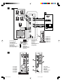
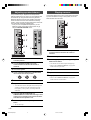
GB
HOME THEATER SOUND SYSTEM
TSS-1
Active Servo
Technology
OWNER’S MANUAL
MODE D’EMPLOI
BEDIENUNGSANLEITUNG
BRUKSANVISNING
MANUALE DI ISTRUZIONI
MANUAL DE INSTRUCCIONES
GEBRUIKSAANWIJZING
DIGITAL
INPUT
4CH
2CH
DTS
MODE
DIGITAL
TEST
PROLOGIC
MUTE
CENTER
SURROUND
SUBWOOFER
MASTER VOLUME
Active Servo
Technology
HOME THEATER SOUND SYSTEM
TSS-1
MS601PRE(9/29)a
1
00.9.29, 2:33 PM
1
A
B
DIGITAL
INPUTS
OPTICAL
SPEAKER
OUTPUTS
L
FRONT
COAXIAL
R
L
SURROUND
R
ANALOG
INPUTS
1
FRONT
SURROUND
2
CENTER
S. WOOFER
SPEAKER
MODE
5CH
4CH
2CH
DIGITAL
INPUT
4CH
2CH
DTS
MODE
DIGITAL
TEST
PROLOGIC
MUTE
DC IN 15V
CENTER
SURROUND
SUBWOOFER
Amplifier unit
Amplifier unit
Amplifier unit
Amplifier unit
Amplifier unit
Amplifier unit
Amplifier unit
MASTER VOLUME
To AC receptacle
Vers une prise du
réceptacle CA
In die Netzsteckdose
Till ett eluttag
Alla presa CA
A la tomacorriente de CA
Naar netaansluiting
PA-SR601:
AC adaptor
Adaptateur CA
Netzteil
Nätadapter
Trasformatore CA
Adaptador de CA
Netadapter
Rear panel
Panneau arrière
Rückseite
Bakpanel
Pannello posteriore
Panel trasero
Achterpaneel
Active Servo
Technology
HOME THEATER SOUND SYSTEM
TSS-1
2
DIGITAL
INPUT
4CH
2CH
DTS
MODE
DIGITAL
TEST
PROLOGIC
MUTE
CENTER
1
2
3
4
5
DIGITAL
INPUTS
OPTICAL
SPEAKER
OUTPUTS
L
COAXIAL
FRONT
B
L
SURROUND
ANALOG
INPUTS
R
6
SURROUND
E
R
1
FRONT
SURROUND
F
2
7
SUBWOOFER
CENTER
S. WOOFER
Front panel
Front panel
Front panel
Front panel
Front panel
Front panel
Front panel
MS601PRE(9/29)a
MASTER VOLUME
Active Servo
Technology
HOME THEATER SOUND SYSTEM
TSS-1
2
8
C
9
0
A
D
SPEAKER
MODE
5CH
4CH
2CH
DC IN 15V
00.9.29, 2:33 PM
Rear panel
Panneau arrière
Rückseite
Bakpanel
Pannello posteriore
Panel trasero
Achterpaneel
English
Thank you for selecting Yamaha TSS-1 Home Theater Sound System.
Cautions
Please read the following operating precautions before use.
YAMAHA will not be held responsible for any damage
and/or injury caused by not following the cautions below.
●
●
●
●
●
●
●
●
●
●
●
●
●
●
●
When you disconnect the AC adaptor from the AC
receptacle, hold the plug itself and not the cord.
If you plan not to use this system for a while, disconnect
the AC adaptor from the AC receptacle.
Always disconnect the AC adaptor from the AC
receptacle before making any connections.
This system does not contain any user serviceable parts.
Refer all servicing to your Yamaha dealer.
Never open the cabinet. If a foreign object drops into
the set, contact your dealer and stop using this system.
Otherwise, you may cause a fire.
Do not expose this system to extreme temperatures,
direct sunlight, excessive dust, humidity, or vibration.
Position this system on a level, stable surface. Do not
drop, apply excessive force to their controls, or put heavy
items on top of them.
Do not place small metallic objects on this system.
Otherwise, the object may fall, possibly causing an injury.
Since the amplifier unit has a built-in power amplifier,
heat will radiate from the ventilation slits. Place the
amplifier unit apart from the walls, allowing a space of at
least 20 cm (7-7/8”) above, 10 cm (3-15/16”) behind and
on both sides of the amplifier unit.
Also, do not position with the rear panel facing down on
the floor or other surfaces and do not cover the amplifier
unit with a newspaper, a tablecloth, a curtain, etc. in
order not to obstruct heat radiation.
If the temperature inside the amplifier unit rises, it may
cause fire, damage to the amplifier unit and/or personal
injury.
Do not place the following objects on this system:
Glass, china, etc.
If glass etc. falls by vibrations and breaks, it may cause
personal injury.
A burning candle etc.
If the candle falls by vibrations, it may cause fire and
personal injury.
A vessel with water in it
If the vessel falls by vibrations and water spills, it may
cause damage to this system, and/or you may get an
electric shock.
To protect this system, avoid microphone feedback,
continuous and excessive output from electronic musical
instruments, and excessive signal distortion.
If this system is located close to a monitor, or fluorescent
or neon lights, a slight hum may be heard. In this case,
relocate this system away from the light.
Although this system is magnetically shielded, keep
floppy disks and tapes away from it.
●
●
Avoid sources of hum (transformers, motors). To prevent
fire or electrical shock, do not expose to rain or water.
Do not use force on switches, knobs, or cables. When
you move this system, first turn off the power, then
disconnect the AC adaptor from the AC receptacle and
the cables from the connected devices.
Always set the MASTER VOLUME control fully to the left
before starting to play the audio source: turn the control
gradually after the play has started.
Be sure to use the AC adaptor (PA-SR601) supplied
with this system. Otherwise, you might cause a fire
or damage to this system.
Standby mode
When this system is turned off by pressing the power
switch, this system consumes a small amount of power.
This state is called the standby mode. The power
supply is completely cut off from the AC line only when
the AC adaptor is disconnected.
This system features a magnetically shielded design, but
there is still a chance that placing it too close to a TV or
a computer monitor might impair picture color. Should
this happen, move this system away from the TV or the
computer monitor.
For U.K. customers
If the socket outlets in the home are not suitable for the plug
supplied with this appliance, it should be cut off and an
appropriate 3 pin plug fitted. For details, refer to the
instructions described below.
Note: The plug severed from the mains lead must be
destroyed, as a plug with bared flexible cord is hazardous if
engaged in a live socket outlet.
SPECIAL INSTRUCTIONS FOR U.K. MODEL
IMPORTANT:
THE WIRES IN MAINS LEAD ARE COLOURED IN
ACCORDANCE WITH THE FOLLOWING CODE:
Blue: NEUTRAL
Brown: LIVE
As the colours of the wires in the mains lead of this
apparatus may not correspond with the coloured
markings identifying the terminals in your plug, proceed
as follows: The wire which is coloured BLUE must be
connected to the terminal which is marked with the letter
N or coloured BLACK. The wire which is coloured
BROWN must be connected to the terminal which is
marked with the letter L or coloured RED. Making sure
that neither core is connected to the earth terminal of the
three pin plug.
E-1
SR601ENG(9/29)e
1
00.9.29, 2:34 PM
Contents
Cautions .......................................................... 1
Controls & connectors ................................. 6
Unpacking ...................................................... 2
Adjusting speaker balance ........................... 8
Features ......................................................... 2
Playing a source ............................................ 8
Setting up the speakers ................................ 4
Troubleshooting ............................................ 9
Connections .................................................. 6
Specifications .............................................. 10
Unpacking
Features
After unpacking, check that the following parts are
contained.
● Amplifier unit
● Satellite speaker x 5
●
●
Satellite speaker with a 3 m cord x 3
Satellite speaker with a 7 m cord x 2
● Subwoofer
● Accessories
●
●
●
●
●
●
●
Mini plug cable x 2
Optical fiber cable x 1
Coaxial cable x 1
Stand for the amplifier unit x 1
Screw x 2
Pad x 16
Fastener x 1
Multi-Channel Surround System for Home
Theater, Game Amusement and PC DVD.
●
Combination of Amplifier Unit, Five Satellite
Speakers and Subwoofer
●
Dolby Digital and DTS decoder
●
5.1-Channel Full-Scale System for DVD Movie
Entertainment
●
5.1-Ch Full-Scale, 4.1-Ch (Game Surround)
and Stereo (Virtual Surround) Speaker Modes
●
Yamaha’s Exclusive Active Servo Technology
for Powerfull Bass Response
●
1 Optical and 1 Coaxial Digital Input Terminals
●
Two Analog Input Terminals (front/rear
channel)
●
Test Tone Generator for Accurate Speaker
Settings
(Refer to the next page.)
E-2
SR601ENG(9/29)e
2
00.9.29, 2:34 PM
English
Welcome to the exciting world of digital home entertainment.
The TSS-1 is a compact, but complete and advanced home theater sound system that takes you to the exciting world of digital
surround sound entertainment. Though some of the advanced features of this system may not be familiar to you, they are easy
to use. Incorporated state-of-art technology such as Dolby Digital and DTS can bring the same audio experience to your home
as they have brought to feature films in quality theaters around the world. Take some time now to read more about these
features and enjoy the new experiences this system brings to your home theater.
■ Dolby Surround
Dolby Surround uses four discrete channels and five
speakers to reproduce realistic and dynamic sound effects:
two main channels (left and right), a center channel for
dialog, and a rear channel for special sound effects. The
rear channel reproduces sound within a narrow frequency
range.
Most video tapes and laser discs include Dolby Surround
encoding, as do many TV and cable broadcasts. The Dolby
Pro Logic decoder built into this unit employs a digital signal
processing system that stabilizes each channel for even
more accurate sound positioning than is available with
standard analog processors.
■ Dolby Digital *
Dolby Digital is a digital surround sound system that
provides completely independent multi-channel audio to
you. Dolby Digital provides five full-range channels in what
is sometimes referred to as a “3/2” configuration: three front
channels (left, center and right), and two surround channels.
A sixth bass-only effect channel is also provided for output
of LFE (low frequency effect), or low bass effects that are
independent of other channels. (This is called the “LFE
channel”.) This channel is counted as 0.1, thus giving rise to
the term 5.1 channels in total.
The wide dynamic range of sound reproduced by the five
full-range channels and precise sound orientation by digital
sound processing provides listeners with excitement and
realism that have never been experienced before.
■ DTS (Digital Theater System) Digital
Surround **
DTS was developed to replace the analog soundtracks of
movies with six discrete channels of digital soundtracks,
and it is now installed in many theaters around the world.
The DTS digital playback system changed the way we
experienced movies in theaters with six discrete channels of
superb digital audio.
DTS technology, through intense research and development
has made it possible to deliver similar encode/decode
discrete technology to home audio surround-sound
entertainment.
DTS Digital Surround is an encode/decode system which
delivers six channels of master-quality, 20-bit audio;
technically, it is 5.1 channels, which means 5 full-range (left,
center, right and two surround) channels, plus a subwoofer
(LFE) channel (as “0.1”). It is compatible with the 5.1
speaker configurations that are currently available for home
theater systems.
Notes
● When playing an ordinary CD on this system following
playback of a CD or an LD encoded with DTS, some
operations, such as resetting input modes, may be required.
● Even if connected to this system with a digital connection,
some CD, LD, and DVD players may make this system fail to
decode DTS or produce noise. This is because certain digital
output data processing by such a player results in DTSencoded data errors that cause playback failure although the
same data processing may cause only a slight change in
volume or in frequency response in normal digital sound.
● When an error occurs in the player’s digital output data during
playback of an LD or CD encoded with DTS, playback may
be disrupted. If this occurs, stop playback and repower the
player.
● When digital sound signals from the computer are played,
errors in WAVE signals, etc. may occur resulting in noise or a
playback failure.
*
Manufactured under license from Dolby Laboratories.
“Dolby”, “Pro Logic” and the double-D symbol are
trademarks of Dolby Laboratories. Confidential
Unpublished Works. q1992–1997 Dolby Laboratories,
Inc. All rights reserved.
**
Manufactured under license from Digital Theater
Systems, Inc. US Pat. No. 5,451,942 and other worldwide patents issued and pending. “DTS”, “DTS Digital
Surround”, are trademarks of Digital Theater Systems,
Inc. Copyright 1996 Digital Theater Systems, Inc. All
Rights Reserved.
E-3
SR601ENG(9/29)e
3
00.9.29, 2:34 PM
Setting up the system
System configuration
Recommended speaker placement
This system includes an amplifier unit, five satellite
speakers and a subwoofer.
The three satellite speakers with a 3 m cord are used for
front speakers and a center speaker.
The two satellite speakers with a 7 m cord are used for
surround speakers.
Before making connections, place all speakers in their
respective positions. The positioning of the speakers is
important because it controls the whole sound quality of this
system.
Place the speakers depending on your listening position by
following the instructions below.
* The satellite speakers can be mounted on a wall.
The roll of respective speakers
The front speakers are used for outputting main channel
sound. The surround speakers are used for effect sounds,
and the center speaker is for center channel sound (dialog
etc.).
The subwoofer is used for outputting sounds of low
frequencies from the front, center and surround channels.
The subwoofer also outputs sounds of the subwoofer
channel when a source is played with DTS or Dolby Digital
decoded.
Front speakers:
On both sides of and at approximately
the same height as the TV (or computer
monitor).
Surround speakers:
Behind your listening position or on
both sides of the listening room.
Center speaker:
Precisely between the front speakers.
* Though the center speaker can be
mounted on the monitor as shown on
the next page, it is not so
recommended for safety.
Subwoofer:
On the foor. The position of the
subwoofer is not so critical because low
bass tones are not highly directional.
It is recommended to place the
subwoofer obliquely facing the wall.
Now making an
illustration
E-4
SR601ENG(9/29)e
4
00.9.29, 2:34 PM
m Mounting a center speaker on top of the
monitor
The front angle of the satellite speakers can be adjusted as
shown below.
When placing the center speaker on top of the monitor,
remove the stand from the speaker, and put the provided
fastener at the bottom of the speaker and on top of the
monitor to prevent the speaker from falling.
* Do not mount the speaker on top of the monitor with an
inclination to a level surface of more than 10 degrees.
1
Loosen the screw on the bottom of the speaker stand.
* Put the supplied nonskid pads at the four corners on
the bottom of the stand to obtain more stability.
Now making an
illustration
Pads
2
English
m Adjusting the front angle of the satellite
speakers
Slide the speaker on the stand as you prefer, and then
tighten the screw.
Note
m Mounting satellite speakers on a wall
The satellite speakers can also be hung on the wall.
Fasten screws into a firm wall or wall support as shown in
the figure, and hang the slits on the rear of the speaker on
the protruding screws.
* Make sure that the screws are securely caught by the
slits.
Tapping screw (4 mm)
(Available at the hardware store)
4 mm
Though this speaker is a magnetically shielded type, there
may be some influence on a monitor picture depending on the
type of monitor or the placement of the speaker. In such a
case, place the speaker apart from the monitor so that there is
no influence on the monitor picture.
m Mounting the amplifier unit on the supplied
stand
To obtain stability, it is recommended to mount the amplifier
unit to the supplied stand with the supplied screws as
shown below.
* Put the supplied nonskid pads at the four corners on the
bottom of the stand to obtain more stability.
Min.
20 mm
Wall/ wall
support
50 mm
Pads
Warning
● Each speaker weighs 0.4 kg (0.9 lbs.). Do not mount them
on thin plywood or a wall with soft surface material. If
mounted, the screws may come out of the flimsy surface
and the speakers may fall. This damages the speakers or
causes personal injury.
● Do not install the speakers to a wall with nails, adhesives, or
any other unstable hardware. Long-term use and
vibrations may cause them to fall.
● To avoid accidents resulting from tripping over loose
speaker cords, fix them to the wall.
SR601ENG(9/29)e
5
E-5
00.9.29, 2:34 PM
Connections
(See figure 1 on inside of the front cover.)
Caution: Plug in the amplifier unit and other
equipment after all connections are
completed.
A : Connect three satellite speakers with a 3 m cord to the
FRONT L, R and CENTER terminals. Connect two
satellite speakers with a 7 m cord to the SURROUND
L and R terminals. Connect the subwoofer to the
SUBWOOFER terminal.
B : Connect external audio/video units (a personal
computer, a video game player, a portable DVD/CD
player, a video cassette player, etc. which send
playback signals to this system) to these terminals.
Cautions
● When placing the provided AC adapter on the desk, etc.,
be sure to fix the adapter on the desk, etc. to prevent it
from falling. If the adapter falls, it may cause personal
injury or damage to the adapter and/or other equipment.
● The SPEAKER OUTPUT terminals on the rear of the
amplifier unit are special for connecting with the supplied
speakers. Never connect these terminals to an AV amplifier
or a power amplifier, otherwise it may cause not only a
misoperation of this system, but also damage to this
system.
Controls & connectors
(See figure 2 on inside of the front cover.)
1
INPUT selector button and indicators
PROLOGIC:
Select this mode to reproduce an input source with
Dolby Prologic decoded.
This mode can be selected only when input signal is
encoded with Dolby Prologic. This mode cannot be
selected when the input mode is set to 4CH.
Press this button repeatedly to select an input mode
between DIGITAL, 4CH and 2CH. The current mode is
shown by the lighting of the corresponding indicator.
DIGITAL:
Select this mode to reproduce signals received at the
OPTICAL or the COAXIAL terminal on the rear panel.
When both OPTICAL and COAXIAL terminals receive
signals, the signals at the OPTICAL ternminal are
selected.
4CH:
Select this mode to reproduce signals received at the
FRONT and SURROUND terminals on the rear panel
in a 4 channel surround sound mode. (The center
speaker is not used in this mode.)
* If a signal encoded with DTS or Dolby Digital is
inputted with no surround mode selected, the
corresponding indicator lights up dimly.
3
Press this button to output a test tone from the
speakers. A test tone is outputted from the front,
center, surround and subwoofer in turn. The test tone is
used for adjusting volume balance among all the
speakers.
* Not all of the speakers output the test tone depending
on the setting of the SPEAKER MODE switch (C).
2CH:
Select this mode to reproduce signals received at the
FRONT terminals on the rear panel in a 2-channel
stereo mode.
2
MODE selector button and indicators
TEST key
4
MUTE button and indicator
Press this button to cut off sound output temporarily.
When this function is active, the indicator lights up.
Press this button again to restore sound output.
* Sound output will also be restored by changing the
status of this system between standby and power-on
modes, and changing the input mode or the surround
mode.
Press this button repeatedly to select the desired
surround mode between DTS,
DIGITAL,
PROLOGIC and off. The current mode is shown by the
lighting of the corresponding indicator. When no mode
is selected, no indicator lights up.
DTS:
Select this mode to reproduce an input source with
DTS decoded.
This mode can be selected only when the input signal
is encoded with DTS and the input mode is set to
DIGITAL.
5
DIGITAL:
Select this mode to reproduce an input source with
Dolby Digital decoded.
This mode can be selected only when the input signal
is encoded with Dolby Digital and the input mode is set
to DIGITAL.
6
CENTER level control
This control is used for adjusting the level of sound
outputted from the center speaker. Turn this control
clockwise to increase the level, and counterclockwise
to decrease the level.
SURROUND level control
This control is used for adjusting the level of sound
outputted from the surround speakers. Turn this control
clockwise to increase the level, and counterclockwise
to decrease the level.
E-6
SR601ENG(9/29)e
6
00.9.29, 2:34 PM
SUBWOOFER level control
This control is used for adjusting the level of sound
outputted from the subwoofer. Turn this control
clockwise to increase the level, and counterclockwise
to decrease the level.
8
D
E
MASTER VOLUME control
OPTICAL:
Connect an external unit (a DVD/CD player, an MD
recorder, a video game player, etc.) which has an
optical digital signal output terminal to this terminal by
using the supplied optical cable.
Headphone jack
Power indicator
Lights up when the power of this system is on.
A
Power switch
Each press of this switch changes the status of this
system between standby mode and power on. When
the power is on, the power indicator (0) lights up.
* Note that this system uses a small amount of power
in the standby mode.
B
SPEAKER OUTPUTS
FRONT:
Connect one satellite speaker with a 3 m cord to the L
terminal and another to the R terminal. They are used
as the front speakers.
SURROUND:
Connect one satellite speaker with a 7 m cord to the L
terminal and the other to the R terminal. They are used
as the surround speakers.
DIGITAL INPUTS
External units which has digital signal output terminals
can be connected to these terminals.
Input signals received at the OPTICAL terminal have
priority over the signals at the COAXIAL terminal.
When both terminals receive signals, the signals at the
OPTICAL terminal are reproduced with this system.
Stereo headphones can be connected to this mini-jack
for private listening. Sound output from the speakers
are cut off when headphones are connected to this
jack.
Sounds of all channels are mixed into 2-channels and
outputted from the headphones.
0
DC IN connector
Connect the supplied AC adaptor to this connector.
This control is used for adjusting the whole volume
level of this system. Turn this control clockwise to
increase the level, and counterclockwise to decrease
the level.
9
English
7
COAXIAL:
Connect an external unit (a DVD/CD player, an MD
recorder, a video game player, etc.) which has an
coaxial digital signal output terminal to this terminal by
using the supplied coaxial cable.
F
ANALOG INPUTS
Connect analog signal output terminals of an external
unit to these mini-jack terminals by using the supplied
mini plug cables or commercially available pin-to-mini
plug cables.
FRONT:
Connect an analog (stereo) signal output terminal of an
external unit to this terminal by using a supplied mini
plug cable. When you connect a sound board on a
computer which has four channel output terminals,
connect the front channel output terminal of the sound
board to this terminal.
SURROUND:
When you connect a sound board on a computer which
has four channel output terminals, connect the rear
channel output terminal of the sound board to this
terminal.
CENTER:
Connect one satellite speaker with a 3 m cord to this
terminal. It is used as the center speaker.
C
SPEAKER MODE switch
Normally, set this switch to 5CH. According to your
preference, set this switch to another position.
5CH:
All speakers are used in this mode.
4CH:
Select this position when you will not use the center
speaker. In this mode, center sound is outputted from
the front L and R speakers.
2CH:
Select this position when you wish to output sounds in
2-channels only. In this mode, sounds of all channels
are mixed and outputted from the front L and R
speakers. The surround speakers output the same
sounds as the front speakers.
E-7
SR601ENG(9/29)e
7
00.9.29, 2:34 PM
Adjusting speaker balance
This procedure lets you adjust the sound output level
balance between the front, center, surround speakers and
the subwoofer by using the built-in test tone generator.
Make this adjustment so that each speaker output level
becomes almost the same when heard at the listening
position. This is important for high performance of the builtin DTS decoder and Dolby Digital decoder.
* Once you have completed this adjustment, you can
adjust the overall volume level of this system only by
using the MASTER VOLUME control.
Playing a source
This section explains how to turn on this system and select
input sources. Before turning on this system, turn on the
external audio unit to be used.
DIGITAL
3
6
INPUT
4CH
2CH
DTS
MODE
DIGITAL
TEST
PROLOGIC
MUTE
CENTER
DIGITAL
INPUT
SURROUND
DIGITAL
INPUTS
OPTICAL
4CH
2CH
DTS
SPEAKER
OUTPUTS
MODE
DIGITAL
L
TEST
PROLOGIC
MUTE
5, 8
FRONT
SUBWOOFER
COAXIAL
R
1, 5
L
CENTER
SURROUND
R
1
4, 7
SURROUND
ANALOG
INPUTS
FRONT
MASTER VOLUME
SURROUND
Active Servo
2
Technology
HOME THEATER SOUND SYSTEM
TSS-1
CENTER
SUBWOOFER
2, 6
1
SPEAKER
MODE
5CH
4CH
2CH
MASTER VOLUME
DC IN 15V
Active Servo
Technology
HOME THEATER SOUND SYSTEM
TSS-1
2
S. WOOFER
1
Turn the MASTER VOLUME control fully
counterclockwise to decrease the volume to
minimum.
2
Turn on this system.
3
Select the appropriate input mode by pressing the
INPUT selector button.
3
1
Set the SPEAKER MODE switch to “5CH” if it is set
to another position.
2
Turn the MASTER VOLUME control fully
counterclockwise to decrease the volume to
minimum.
* The indicator for the selected input mode lights up.
* Refer to the “Controls & connectors” on page 4 for
details about the input modes.
3
Turn on this system.
4
Play s source on the external unit.
4
Set the CENTER, SURROUND and SUBWOOFER
level controls at the center position.
5
Adjust the volume to the desired level.
6
As you prefer, select a surround mode.
CENTER
SUBWOOFER
SURROUND
* Refer to the “Controls & connectors” on page 4 for
details about the surround modes.
5
Press the TEST button.
6
Adjust the master volume to the desired level.
* You will hear a test tone (like pink noise) from respective
speakers for about two seconds in the following order:
front speakers, center speaker, surround speakers and
subwoofer .
7
Adjust the CENTER, SURROUND and
SUBWOOFER level controls while listening a series
of test tones so that their levels become almost the
same with the front speakers’ level.
8
When the adjustment is completed, press the TEST
button.
* The test tone stops .
E-8
SR601ENG(9/29)e
8
00.9.29, 2:34 PM
Refer to the chart below when the speakers do not function properly. If the problem you are experiencing is not listed below or
if the instructions given below do not help, disconnect the AC adaptor and contact your authorized YAMAHA dealer or service
center.
Cause
Problem
What to Do
The AC adaptor is not properly plugged into
the AC receptacle.
Insert the AC adaptor firmly into the AC
receptacle.
The power of this system is set to off.
Turn on the power by pressing the power
switch. (The power indicator lights up.)
Connections are faulty or incomplete.
Make the connections again.
Appropriate input mode is not selected.
Select the appropriate input mode by
pressing the INPUT selector button.
The volume setting is low.
Turn the MASTER VOLUME control
clockwise to increase the volume.
The MUTE function is active. (The indicator
on the left side of the MUTE button is
illuminated.)
Press the MUTE button to cancel this
function. (Some other operations also cancel
this function.)
The SURROUND level control is set to
minimum.
Turn the SURROUND level control clockwise
to increase the level.
No surround mode is selected.
Select the appropriate surround mode by
pressing the MODE button. If no mode can
be selected, change the input source to
another which is encoded with DTS, Dolby
Digital or Dolby Prologic.
The CENTER level control is set to minimum.
Turn the CENTER level control clockwise to
increase the level.
The SPEAKER MODE switch on the rear
panel of the amplifier unit is set to “2CH” or
“4CH”.
Set the SPEAKER MODE switch to “5CH”.
No surround mode is selected.
Select the appropriate surround mode by
pressing the MODE button. If no mode can
be selected, change the input source to
another which is encoded with DTS, Dolby
Digital or Dolby Prologic.
No sound from the center and
surround speakers though the DTS or
DIGITAL mode indicator is
illuminated.
Dim illumination of an indicator means that
signals encoded with the corresponding
format (DTS or Dolby Digital) is inputted to
this system. In this case, the signals are
mixed into 2-channels and outputted from the
front speakers only.
Press the MODE button for the appropriate
surround format. The indicator turns bright,
and the center and surround speakers output
sounds since the surround format is decoded.
The
DIGITAL mode indicator is
dimly illuminated and the
PROLOGIC mode indicator is brightly
illuminated.
The input source encoded with Dolby Digital
may be originally in 2-channel mode.
Check the setting of the digital output on the
player which is sending input signals to this
system. If the input source is originally in 2channel mode, use the
PROLOGIC mode
to enjoy the source in a multi-channel mode.
Sound is distorted.
The level of the signal being inputted is too
low.
Turn up the volume on the connected
component.
Noise.
The level of the signal being inputted is too
high.
Turn down the volume on the connected
component.
Connections are faulty or incomplete.
Make the connections again.
The amplifier unit is near the monitor.
Place the amplifier away from the monitor.
No sound comes from the speakers or
subwoofer.
No sound from the surround speakers
No sound from the center speaker
English
Troubleshooting
E-9
SR601ENG(9/29)e
9
00.9.29, 2:34 PM
Specifications
Control unit
Satellite speaker
Minimum RMS Output Power per Channel
........................ 20W + 20W (20 Hz–20 kHz, 6Ω, 0.4% THD)
Type ............... 2-way 2-speaker bass-reflex speaker system
Magnetically shielded type
Maximum Power .......... 26W + 26W (1 kHz, 6Ω, 10% THD)
Input Sensitivity/Input Impedance
PC IN, AUX1 IN, AUX2 IN (ANALOG) ........ 150 mV/35 kΩ
Driver
Woofer ........................................ 9 cm (3-9/16”) cone type
Tweeter ........................... 2.5 cm (1”) balanced dome type
Maximum Input Signal
PC, AUX1, AUX2 .............................. 2.1V or more (1 kHz)
Nominal Input Power .................................................. 40W
Output Level/Output Impedance
REC OUT ................................................... 150 mV/2.0 kΩ
SUBWOOFER OUTPUT .................... 2.0V/1.7 kΩ (50 Hz)
Headphone Jack Output Level/Output Impedance
ANALOG PC IN, etc. .......... 320 mV/61Ω (1 kHz, 150 mV)
Frequency Response
USB, DIGITAL IN (PC, AUX1) to SP Output
.................................................... 20 Hz–20 kHz (51.0 dB)
Total Harmonic Distortion (1 kHz, 20 kLPF)
USB, DIGITAL IN (PC, AUX1) to SP Output
........................................................ 0.06% or less (4V/6Ω)
Signal to Noise Ratio
USB to SP Output ...................... 85 dB or more (11V/6Ω)
PC IN, AUX1 IN (DIGITAL) to SP Output
..................................................... 90 dB or more (11V/6Ω)
Residual Noise (IHF-A Network)
......................................... –68 dB or less (SP Output, L/R)
Power Supply
[U.S.A. and Canada models] .................. AC 120V, 60 Hz
[Europe and U.K. models] ...................... AC 230V, 50 Hz
[Australia model] .................................... AC 240V, 50 Hz
Power Consumption
[U.S.A. and Canada models] .................................... 60W
[Europe, U.K. and Australia models] ....................... 55W
Dimensions (W 2 H 2 D) .............. 120 2 294 2 355 mm
(4-3/4” 2 11-9/16” 2 14”)
Weight ................................................. 5.5 kg (12 lbs. 2 oz.)
Maximum Input Power .............................................. 100W
Impedance ...................................................................... 6Ω
Frequency Response ................................. 75 Hz – 33 kHz
Sensitivity .................................................... 88 dB/2.83V/m
Crossover Frequency ................................................ 7 kHz
Dimensions (W x H x D) ....... 107 mm x 191 mm x 141 mm
(4-3/16” x 7-1/2” x 5-9/16”)
Weight .............................................. 1.5 kg (3 lbs. 5 oz.) x 4
Subwoofer
Type ................ Active Servo Processing Subwoofer System
Driver ............................... 20 cm (8”) cone woofer (JA2162)
Magnetically shielded type
Amplifier Output ..................................................... 70W/5Ω
High-Cut Filter ...................... 50 Hz – 150 Hz (–24 dB/oct.)
Frequency Response .................. 30 Hz – 200 Hz (–10 dB)
Dimensions (W x H x D) ....... 235 mm x 365 mm x 318 mm
(9-5/16” x 14-7/20” x 12-1/2”)
Weight .................................................. 9 kg (19 lbs. 13 oz.)
Accessories
Mini plug cable x 2
Optical fiber cable x 1
Coaxial cable x 1
Stand for the amplifier unit x 1
Screw x 2
Pad x 16
* Please note that all specifications are subject to change
without notice.
E-10
SR601ENG(9/29)e
10
00.9.29, 2:34 PM