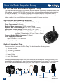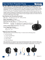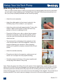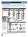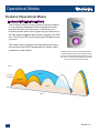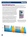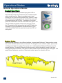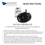
1
EcoSmart
User Manual
Revision 1.0
Contents
Chapter 1: Before You Start
Section 1.0: Introduction
Section 1.1: Safety Warnings
Chapter 2: Your VorTech Propeller Pump
Section 2.0: VorTech MP40w EcoSmart
Section 2.1: VorTech MP10 EcoSmart & MP10w EcoSmart
Chapter 3: Setup Your VorTech
Section 3.0: Pump Positioning
Section 3.1: Spacing VorTech Pump Section 3.2: Attaching VorTech Pump Section 3.3: Aligning VorTech Pump
Section 3.4: EcoSmart Driver
Section 3.5: Powering Your EcoSmart Driver
Section 3.6: Master/Slave/Independent
Section 3.7: Assigning Master/Slave Relationship
Section 3.8: Assigning Local Max Speed to a Slave
Chapter 4: Operational Modes
Section 4.0: Navigating Between Modes
Section 4.1: EcoSmart Operational Modes
Section 4.2: General Operational Modes
Section 4.3: Auto-Tune & Wave Motion Warning
Section 4.4: Other Modes
Section 4.5: Configuration Mode
Chapter 5: Pump Configuration for EcoSmart
Section 5.0: What Does EcoSmart Mean to You?
Section 5.1: Use of EcoSmart with Wireless Wave Driver
Section 5.2: Horizontal & Vertical Pump Positioning
Section 5.3: MP10’s Aren’t Just for Nano Tanks Anymore
Section 5.4: Advanced EcoSmart Pump Positioning
Chapter 6: Maintenance
Section 6.0: General Maintenance
Section 6.1: Disassembling Wet-Side
Section 6.2: Wireless Driver Firmware Upgrade
Section 6.3: Pump Disconnect Error Protection
Chapter 7: Troubleshooting
Section 7.0: Error Codes
Section 7.1: FAQS
Chapter 8: Appendix
2
Section 8.0: Contact Us
Section 8.1: Warranty
Section 8.2: FCC and CE Warnings
Page
3
4
6
7
8
9
10
11
12
13
14
15
16
18
19
21
25
26
28
32
32
33
33
34
35
35
36
38
39
40
41
42
43
Before You Start
Introduction
Thank You For Choosing EcoTech Marine!
EcoTech Marine has revolutionized reef aquarium propeller pumps with its award-winning line of
VorTech products and accessories for aquariums ranging from 2.5 to 500+ gallons. Every product
from EcoTech Marine is backed with our industry-leading customer service.
Please Register Your Product
Registering your product guarantees that you will receive service and support in the event of a warranty claim. Additionally, you will be eligible to recieve exclusive offers and upgrades to our registered customer base. To register your product, please visit our customer support section at www.
ecotechmarine.com. You will need the product’s serial number which is located on the back of your
pumps driver.
Optimal Use of Your Pump
To fully utilize the functionality of your new VorTech Propeller pump, please read this manual before
you begin for information on the placement, operational modes, wireless configuration of mutiple
pumps and troubleshooting of your new VorTech pump and EcoSmart Driver.
3
Section 1.0
Before You Start
IMPORTANT: Safety Warnings
• The VorTech utilizes very powerful magnets and can cause severe personal injury.
• NEVER connect the two halves of this device without a proper spacer in-between.
• NEVER place either half of this device near magnetically attractive surfaces or sensitive electronics.
• The motor and driver can become HOT. Be cautious around these surfaces.
• Never run the pump dry as the heat buildup may cause damage to its components.
• Do Not Drop Your VorTech Pump - VorTech pumps are highly engineered to be as small and
powerful as possible. As a result the VorTech pump is fragile. All precautions must be taken to
avoid dropping the wet-side and dry-side. After a fall onto the floor, both the wet side and dry
side can be permanently damaged. Evidence of this include cracking of the advanced ceramic
axle within the wet side (MP10 versions only), or the dry side running loudly. The VorTech
pump SHOULD NEVER BE ALLOWED TO FALL to the floor. Damage from dropping will not
be covered under warranty.
• Operation is subject to the following two conditions: (1) this device may not cause interference,
and (2) this device must accept any interference including interference that may cause undesired operation of the device.
• Changes or modifications not expressly approved by EcoTech Marine could void the user’s
authority to operate the VorTech Wireless Wave Driver.
• This product carries an ingress protection rating of IPX0 and must not
be immersed in water.
• Danger: To avoid possible electrical shock, special care should be
taken since water is employed in the use of aquarium equipment. For
each of the following situations, do not attempt repairs yourself; return
the appliance to the manufacturer for service or discard the appliance.
CAUTION: Keep Dry-Side
Contents away from water.
• DO NOT immerse in water. If the appliance falls into the water, DON’T reach for it! First unplug
it and then retrieve it. If electrical components of the appliance get wet, unplug the appliance
immediately. (Non- immersible equipment only)
• Carefully examine the appliance after installation. It should not be plugged in if there is water
on parts not intended to be wet.
• Do not operate any appliance if it has a damaged cord or plug, or if it is malfunctioning or if it
is dropped or damaged in any manner. The power cord of this appliance cannot be replaced: If
the cord is damaged, the appliance should be discarded. Never cut the cord.
• To avoid the possibility of the appliance plug or receptacle getting wet, position aquarium stand
and tank to one side of a wall mounted receptacle to prevent water from dripping onto the
receptacle or plug. The “drip-loop” should be arranged by the user for each cord connecting an
aquarium appliance to a receptacle. A “drip-loop” is that part of the cord below the level of the
receptacle, or the connector if an extension cord is used, to prevent water traveling along the
cord and coming in contact with the receptacle. If the plug or receptacle does get wet, DON’T
unplug the cord. Disconnect the fuse or circuit breaker that supplies power to the appliance,
then unplug and examine for presence of water in the receptacle.
4
Section 1.1
Before You Start
IMPORTANT: Safety Warnings (cont.)
• Close supervision is necessary when an appliance is used by or near children.
• To avoid injury, do not contact moving parts or hot parts such as heaters, reflectors, lamp
bulbs, and the like.
• Always unplug an appliance from an outlet and battery backup when not in use, before putting
on or taking off parts, and before cleaning.
• Never yank cord to pull plug from outlet. Grasp the plug and pull to disconnect.
• Do not use an appliance for other than intended use. The use of attachments not recommended or sold by the appliance manufacturer may cause an unsafe condition.
• Do not install or store the appliance where it will be exposed to weather or to temperatures
below freezing.
• Make sure an appliance mounted on a tank is securely installed before operating it. Read and
observe all the important notices on the appliance.
5
Section 1.1
Your VorTech Propeller Pump
VorTech MP40w EcoSmart Propeller Pump
The award-winning technology of the MP40w provides wireless operation on tanks between 50 and
500+ gallons, producing 200 to 3,200 gallons per hour of flow and the smallest in-tank footprint for
full-size reef aquariums. The EcoSmart Wireless Driver enables wireless coordination and enhanced functionality between multiple MP40w ES units right out of the box, with no extra equipment
to buy—making it the most effective solution on the market for larger aquariums.
Specifications and Operating Parameters
Flow: 1,000 - 3,200 gallons per hour (3,785 -12,100L per hour)
Power Consumption: 9-28 watts
Maximum Motor Temperature: 50-60 degrees Celsius
Aquarium Wall Thickness Range: 3/16”-3/4” (4.76mm - 19mm)
Appropriate Tank Size Range: 50-500+ gallons (190-1,800L)
Dimensions: Wet-Side - 3” diameter by 2.25” long (76mm x 57mm)
Dry-Side - 3” diameter by 2.25” long (76mm x 57mm)
Clearance Needed Behind Aquarium: 3” (76mm)
Power Supply Specifications:
Input: 100-240V ac 1.2A 50/60 Hz
Output: 24v - 2.5A
Getting to know Your Pump
Open up the box to your new VorTech Pump. You should see the following pieces:
1.) VorTech Wet-Side
2.) VorTech Dry-Side Motor
3.) EcoSmart Driver
4.) Power Cables
5.) Quick Start Manual
When dissambled, the wet-side of your pump looks like the below image. Having the ability to dissasemble the wet-side allows for easy cleaning and maintenance of your pump. For more information on how to dissasemble and clean your pump, see Chapter 5: Maintenance of Your Pump.
Ceramic Bearing
Drive Shaft Nut
Nozzle
6
Drive Shaft Screw
Drive Shaft
Propeller
O-ring
Washer
Wet Frame
Plastic Coated Magnet
Frame Cover
Section 2.0
Your VorTech Propeller Pump
VorTech MP10 EcoSmart & MP10w EcoSmart Propeller Pump
Designed especially for nano-reef aquariums, the MP10 and MP10w from EcoTech Marine are
small yet powerful pumps. The MP10 and MP10w—ideal for tanks from 2.5 to 50 gallons—create
gentle flows of 200 to 1,575 gallons per hour, helping the tanks feel more like the ocean.The MP10
and MP10w share the same award-winning technology as the MP40w and lets you take full control of the flow. Similarly to the MP40w, the MP10w comes with the EcoSmart Wireless Driver that
enables wireless coordination and enhanced functionality between multiiple With all the electrical
components outside the aquarium and a variety of easy-to-program modes, the VorTech is the safest, most versatile pump on the market.
Specifications and Operating Parameters
Flow: 200 - 1,575 gallons per hour (750 - 5962L per hour)
Power Consumption: 8-18 watts
Maximum Tank Thickness: 3/8” (9.5mm)
Appropriate Tank Size Range: 2.5 - 50 gallons (9.5-190L)
Dimensions: Wet-Side - 2.5” diameter by 1.5” long (63.5mm x 38.1mm)
Dry-Side - 2.5” diameter by 2” long (63.5mm x 50.8mm)
Clearance Needed Behind Aquarium: 2.25” (57mm)
Power Supply Specifications:
Input: 100-240V ac 1.2A 50/60 Hz
Output: 24v - 1.5A
Getting to know Your Pump
Open up the box to your new VorTech Pump. You should see the following pieces:
1.) VorTech Wet-Side
2.) Vortech Dry-Side Motor
3.) EcoSmart Driver
4.) Power Cables
5.) Quick Start Manual
When dissambled, the wet-side of your pump looks like the below image. Having the ability to dissasemble the wet-side allows for easy cleaning and maintenance of your pump. For more information on how to dissasemble and clean your pump, see Chapter 5: Maintenance of Your Pump.
Ceramic
Washer
7
Nozzle
Rotor
O-Ring
Wet Frame
with Axle
DrySide
Section 2.1
Setup Your VorTech Pump
Pump Positioning
Preparation
Once you have chosen the location where you wish to install your VorTech pump, clean away any
algae, calcified or otherwise using an aquarium scraper. Use caution when using an aquarium
scraper.
Notes on Placement
The VorTech pumps create a large amount of low velocity flow within your aquarium. Take care to
place the VorTech in a suitable location where corals are not directly in the line of flow. Place the
pump sufficiently high enough above a fine sand bed so that sand is not blown around by the output or undertow created by the VorTech. For more information on pump placement on your tank,
see section 5.2: Horizontal & Vertical Pump Positioning.
Protect the Pump From Water
The VorTech dry-side motor assembling and EcoSmart driver are NOT WATERPROOF. Any water allowed into these components can damage them enough to require replacement. This kind
of damage is NOT covered under EcoTech’s product warranty. Protect these components from
splashes of any kind.
Advanced Pump Positioning
For advanced and complete pump positioning of multiple pumps refer to Chapter 5: Pump Configuration of EcoSmart Modes
8
Section 3.0
Setup Your VorTech Pump
Spacing VorTech Pump
Adjusting the Pin Spacer (MP40w ES Only)
• The VorTech pump is designed to operate with a constant
gap between both halves of the device. The pin spacer is
used to ensure the proper spacing for various aquarium
wall thicknesses.
• Make sure to measure your aquarium’s glass thickness using a ruler or contact the aquarium manufacturer in order to
determine the exact thickness.
• To adjust for the proper aquarium thickness, pull the rubber pin spacer from the motor housing. Then align the
VorTech’s power cord emerging from the motor with your
aquarium’s wall thickness to achieve the proper offset from
your aquarium.
Note: 3/4” thick aquariums do not use the pin spacer at all.
IMPORTANT: When adjusting the pin spacer, be sure not to bend the rubber pins as they are inserted into the
holes within the heat sink as this may permanently damage your VorTech. Bent pins WILL NOT be covered
under warranty
Adding Rubber Spacer (MP10 ES and MP10w ES Only)
• The MP10 ES and MP10w ES will sometimes require you
to adjust the spacing between the dry-side moter and wetside propeller.
• Make sure to measure your aquarium’s glass thickness using a ruler or contact the aquarium manufacturer in order to
determine the exact thickness
• For glass thicknesses of 1/8” and 3/16” you must use the
included rubber spacer in between the motor and the glass.
Failure to use the included rubber spacer on glass thicknesses of 1/8” and 3/16”can damage your pump. Damage
of this sort will not be covered under warranty.
Note: There is no need to use this spacer on glass thicknesses of 1/4” or 3/8”.
9
Section 3.1
Setup Your VorTech Pump
Attaching VorTech Pump
Once you have chosen where to place your pump and you have prepared the area for placement
you are ready to begin attaching your VorTech Pump to the tank. Follow these instructions to ensure your pump is properly attached and will function properly.
• Attach the motor assembly
• Apply the rubber gasket at the chosen location for the
VorTech pump, on the outside of your aquarium.
• Apply the cord mounting tab approximately 2” above this
location. Make sure the glass is clean and free of any
grease or dirt prior to applying this tab.
• Place the VorTech motor, with or without the pin spacer
attached as necessary, upon the black gasket, and secure the cord to the mounting tab using one of the provided wire-ties.
• The cord must be positioned pointing upwards so that
if the VorTech were to fall off the aquarium, it does not
swing and damage your aquarium. When operating,
make sure the gasket is properly recessed within the pin
spacer
• Attach the wetside assembly.
• Place the wet side into the aquarium, making sure to allow ALL air to escape from the propeller housing.
• Carefully connect both halves of the pump together and
visually align both halves of the pump.
Note: Protect the pump from falling. Due to the nature of the magnetically coupled design, it is possible for the VorTech to become dislodged from the aquarium glass and fall to the ground. The cord
should be positioned vertically above the pump with the mounting tab directly above the motor to
ensure that the motor does not move in the event of a decoupling of the magnets. The provided cordmounting tab MUST be used to prevent damage to the motor or the surrounding environment.
10
Section 3.2
Setup Your VorTech Pump
Aligning VorTech Pump
• Turn the speed up to the maximum speed by using the
speed control knob on the driver.
• Plug the power supply into the driver. If vibration or noise is
detected, carefully adjust the propeller housing by moving it
VERY slightly left, right, up or down, until the noise/vibration
is eliminated or minimized as much as possible.
• After alignment has been ensured, turn the speed control
knob to achieve the desired flow rate within your aquarium.
• Important: If the VorTech is not properly aligned, a strong
vibration will be heard. If the alignment is not corrected,
this can cause increased electrical consumption, excessive
wear on the components, excessive heat and excessive
noise.
11
Section 3.3
Setup Your VorTech Pump
EcoSmart Driver (wireless and non-wireless)
The EcoSmart driver unlocks the full potential of your VorTech pump by allowing you to be in
complete control. Capable of controlling your VorTech pump in a variety of different ways, the
EcoSmart driver allows for virtually endless flow possibilities within your reef tank. Please note that
not all EcoSmart drivers are wireless enabled. If your EcoSmart driver is wirelessly enabled the ‘w’
at the top of the driver will illuminate blue.
Specifications
Wireless Enabled: ‘w’ versions only
Dimensions:Length: 5” (127mm)
Width: 3.5” (89mm)
Depth: 1.375” (34.9mm)
Power Input: 24 volt DC input
Battery Backup Input: 12 volt DC input
4.) Wireless Indicator
(Illuminates on wireless versions only.)
1.) Set Button
2.) Mode Button
5.) LED Strip
6.) Option/Power Button
7.) Control Dial
3.) Battery Backup Input
8.) Pump Cable Slot
9.) Power Input
1.) Set Button: Used to set different settings in each operational mode.
2.) Mode Button: Used to select between different operational modes.
3.) Battery Backup Input: Input slot for EcoTech’s Battery Backup for protection against power
failures. Available at your local retailer.
4.) Wireless indicator: Blue LED that will illuminate on wireless versions
5.) LED Strip: Blue LEDs that will illuminate to indicate modes, speeds, time, etc.
6.) Option/Power Button: Used to select different options in certain configuration modes and used
to power pump on/off.
7.) Control Dial: Used to change speeds, times and other settings.
8.) Pump Cable Slot: Input Slot for the pump cord. Note: Pump comes attached to driver.
9.) Power Input: Input slot for attaching the power supply to the pump.
12
Section 3.4
Setup Your VorTech Pump
Powering Your EcoSmart Driver
You EcoSmart Driver now has the capability to be turned off without unplugging the power supply
from your driver. When turned on, the option button can be used simultaneously with either the set
or mode buttons to perform certain configurations. To turn on or off your driver, simply just press the
power/option button. If you have a master/slave relationship setup, the power/option button allows
you to power off locally or power off the whole system, including each slave pump. To power off
just one pump, only press the power/option button. To power off the system of master/slave pumps,
press and hold the power/option. Note: If you power off a system of master/slave pumps together,
you can power them all back on by pressing the option/power button on any of the pumps in that
master/slave relationship. This is useful if you have an EcoTech Marine Battery Backup, so that you
can power off your VorTech Pump without having to unplug your driver from the Battery Backup.
13
Section 3.5
Setup Your VorTech Pump
Master/Slave/Independent
EcoSmart controlled VorTech pumps work together in ways not
previously possible to create a variety of flow options. The EcoSmart
driver comes out of the box in Independent mode. In Independent
mode, the EcoSmart driver does not broadcast wireless signals for
other pumps to hear (with the exception of Feed Mode, which all
pumps broadcast and all pumps listen for). If you are only running
one VorTech propeller pump, then this will be ideal for you. When
you add additional VorTech pumps, any EcoSmart driver is capable
of operating either as a master or a slave pump. A master pump
broadcasts a wireless signal and a slave pump receives this wireless signal. On any one aquarium, you can have up to six different
master pumps broadcasting on unique frequencies. Each of these
master pumps can be synced with an infinite number of slave pumps
for endless flow possibilities.
Driver shown here Independent in Constant Speed Mode
(Green Control Dial).
When a master pump is initiated and running in any one of the normal modes (such as Constant
Speed, Random, Short Pulse, or Long Pulse Mode), it sends out a signal telling other pumps what
mode it is operating and what speed it is running at. VorTech pumps set to operate as slave pumps
will listen for the master pump’s wireless signal and will do either the same as the master pump
(Sync Mode), or the opposite of the
Master
Master Pump shown
master pump (Anti-Sync Mode). Slave
here in Constant Speed
Mode (GreenControl
pumps set in Sync Mode will perform
Dial).
exactly the same as the master pump
and will be indicated by a white LED
on the EcoSmart driver’s knob. Slave
Slave Pumps speed,
Slave Pumps speed,
shown here by the blue
shown here by the blue
pumps set in Anti-Sync Mode will perLED strip, synced with
LED strip, independent
master pump.
of master pump.
form exactly the inverse of the master
pump and will be indicated by an orSlave
Slave
ange LED on the EcoSmart driver’s
Slave
knob.
For example, if the master pump is running at 80% speed, a slave pump in sync mode will run at
80% speed as well. If that same slave pump was operating in Anti-Sync Mode, it will run at 20%
speed (this is the inverse speed of 80%). As the master pump slows down, a slave pump in Sync
Mode will slow down with it and a slave pump in Anti-Sync Mode will speed up.
To select between Sync and Anti-Sync Mode on a slave pump, simply tap the MODE button, the
LED will change color to reflect which mode the pump is in.
For more information on assigning master and slaves, see section 3.5: Assigning Master/Slave Relationship. For more information
on wireless configuration of multiple pumps and pump positioning, see Chapter 5: Pump Configuration of EcoSmart Modes.
14
Section 3.6
Setup Your VorTech Pump
Assigning Master/Slave Relationship
NOTE: When using a single VorTech pump, no master/slave configuration is necessary
When using two or more VorTech pumps, you will want to establish pump groups to coordinate
the operation of multiple pumps. A pump group consists of one master pump and at least one
slave pump. There can only be one master pump per group which can include an unlimited number of slave pumps. In order to set a pump as a master or a slave, the aquarist must first enter
the VorTech Pump’s configuration mode. Within configuration mode one can do one of three different things:
•Reset the pump’s memory back to independent mode
•Set the pump as a master
•Set the pump as a slave
Masters and slaves must be set as groups and each group must be programmed separately. You
must perform the following steps in the order listed to correctly program your EcoSMART driver.
You may setup a maximum of seven separate groups, each having a unique master pump.
• Clear Driver Memory - The internal memory of each unit must be cleared before setting up a
group. Hold Mode and Set together until the control dial blinks red/white/blue. Then hold mode
until the dial blinks red/purple. Then hold Set until the pump resets.
HOLD Mode + Set
*After you hotd Mode and Set
your control dial will blink red/
white/blue.
HOLD Mode
*After holding Mode your control
dial will blink red/purple.
HOLD Set
*Pump shown reset to constant
Speed Mode (Green Dial).
HOLD Mode + Set
• Enter Setup Mode - All pumps in a group must then
be set into configuration mode before the assignment
of slave or master status. This configuration must be
performed with the drivers in close proximity to ensure
proper assignment. Hold Mode and Set together until the
drivers blink red/white/blue.
15
Section 3.7
Setup Your VorTech Pump
Assigning Master/Slave Relationship (cont.)
PRESS Mode
• Assign the Master - Set the master pump by pressing the
mode button. The control dial will then blink blue and green.
You are now ready to assign slave pumps.
• Assign the Slaves - Set the slave pump by pressing the
set button on the driver. The control dial will then blink blue
and yellow. NOTE: If the slave blinks blue and red, it was
too far away from the master driver and could not communicate properly. Repeat this step for all slaves you want to
assign the the master.
PRESS Set
• Reset the Master - Hold the mode button on the master
pump after completing ALL the master/slave assignments.
The pump will reset and begin operation in the previous
mode you had programmed. You can then change modes
with the master pump like normal and the slave pumps
will operate according to what the master pump defines.
Slave pump speeds can be defined by the master or can
be locally defined, See Section 2.3: Assigning a Local Max
Speed to a Slave.
HOLD Mode
*Pump shown reset to constant
Speed Mode (Green Dial).
• Begin Normal Operation - Use the controls on the Master Pump to operate all pumps in the
group. Slave pumps can only be set to sync or anti-sync modes, or the three options in EcoSmart modes. For more information on operating slave pumps and configuration, see Chapter 5:
Pump Configuration for EcoSmart Modes.
• Program Subsequent Groups - Now that the first group is programmed, repeat these steps on
the next group of pumps, if so desired.
• Unassign a Slave Pump - If you would like to unassign a pump as a slave and use it independently, follow instructions for clearing driver memory and perform those steps on the slave pump
which you would like to unassign.
16
NOTE: The subsequent pump groups must be programmed near the original group. For example, if running
two different groups in separate areas of your house, the second group must be programmed within 5 feet the
first group to ensure proper communication.
Section 3.7
Setup Your VorTech Pump
Assigning a Local Max Speed to a Slave
While normally you cannot change the speed of a slave pump, because the speed is determined
entirely by the master pump, with the EcoSmart driver you now have the ability to control the maximum speed of individual slave pumps independently from the master. This will come in handy if
your aquarium setup requires higher flow in most areas but lower flows in other areas such as if a
slave pump is used to provide spot flow to a delicate coral, or if it is used on the back of a narrow
tank. In the default setting, a slave pump will always do exactly the same thing or the inverse of the
master pump (based on whether it is set to Sync or Anti-Sync), and therefore the maximum speed
that a slave pump can achieve is governed by the master pump.
• To assign a unique maximum speed setting to an individual slave
pump, hold the SET button on the slave until a bright LED shows
on the LED strip. This LED represents the locally assigned maximum speed for this slave pump.
• Next, turn the knob to adjust the maximum speed for that particular slave pump, which will be indicated by the LED strip.
• To increase the maximum speed, turn the knob to the right.
• To decrease the maximum speed, turn the knob to the left.
• If you would like to restore the slave pump’s speed setting to
match the master pump’s speed setting, hold the SET button
until the brightly illuminated LED showing the max speed goes to
dim. It will now revert back to always match the speed input by
the master pump.
For more information on setting up your master and slave pumps, see Chapter 5: Pump
Configuration for EcoSmart Modes.
17
Section 3.8
Operational Modes
Navigating between modes
To navigate between the different modes, use the mode, set and option buttons along with the
control dial. Modes will be distinguished by the distinct color of the dial and/or the illumination of
specific blue LED’s on the LED strip. The following will guide you through navigating between each
mode. For more information on each specific mode, see the full description of each mode in the
next section of the manual.
Constant
M
ode
Speed
EcoSMART Driver General Operational Modes
EcoSMART *
Short Pulse
Random*
M
Set
M
ode
M
Reef Crest
Speed Set
Speed Set
Set
Set
Set
Set
Short Pulse
Long Pulse
Random*
*
NTM
Lagoon
Freq. Set
Freq. Set
Set
Set
Set
Set
Saved
Op
tio
/Pw n
r
Note: In Pulse
Modes, when you
save a wave, the
control dial will
blink green/white
twice to indicate
wave is saved. The
control dial will then
breathe the color
corresponding to
the mode you were
in.
(Hold to save,
Press to access)
(Hold) - Feed mode
Wave
Op
tio
/Pw n
r
(Hold) - Powers Off
See Below for Auto Tune
*Note: LED bar will indicate change between modes
Set
Freq. Set
Saved
(Hold to save,
press to access
saved wave)
Op
tio
/Pw n
r
Hold Set and Option
until Blue LEDs roll back
and forth slowly
Set
Wave
Wave
Auto-Tune
Short Pulse
Set
(Hold to save,
Press to access)
Saved
de
Mo
Control Dial
Long Pulse
ode
TSM
EcoSMART
de
Mo
ode
Press
de
Mo
Press
Set
Press Set when you
see a desired wave
form in your tank.
Op
tio
/Pw n
r
Press
To fine tune wave, press the mode to speed
up wave and option to slow down wave. This
will be shown visually with the blue LED strip.
When satisfied, press Set again to save wave.
Note: You are not able to navigate into Auto-Dim or Night Mode from regular operation. These
modes are automatic after you configure them in Configuration Mode. For instructions on how to
configure these modes, see Section 4.5: Configuration Mode.
18
Section 4.0
Operational Modes
EcoSmart Operational Modes
EcoSmart TSM (Tidal Swell Mode)
This EcoSmart mode is used to create a harmonic balance
in your aquarium reminiscent of the changing flow conditions that would be found in nature. In this mode, your
EcoSmart master driver will be purple and your slave driver
will flash white/orange/teal and indicate it speed by the LED
strip. The first two LED’s will indicate which EcoSmart mode
you are in.
This mode would be great for ultra high energy reef tanks,
such as those that an SPS keeper seeks to create, and is
represented visually below:
Illustration above shows an EcoSmart Driver in
EcoSmart Mode (Purple Control Dial). The first
and second brightly illuminated LEDs show that
this driver is set to EcoSmart TSM along with the
dim LEDs showing the speed setting.
100%
Back
% of user
set speed
Opposite
Same
50%
(time)
19
Section 4.1
Operational Modes
EcoSmart NTM (Nutrient Transport Mode)
In this EcoSmart mode, water is circulated in a two phase program to promote maximum health
and nutrient export, as well as increased growth for sensitive corals such as SPS. In this
mode,your EcoSmart master driver will be purple and your slave driver will flash white/orange/teal
and indicate its speed by the LED strip. The third and fourth LED’s will indicate which EcoSmart
mode you are in. This mode is represented in the image below:
Phase one, or the wave phase, consists of the pumps pulsing at an expanding frequency so as to achieve a resonant
wave in any aquarium at some point in the pulse cycle. If
you have already tuned a wave form into your EcoSMART
driver by using the auto-tune function in Short Pulse Mode,
this saved resonant wave will automatically be used during
phase one of the this mode. The pulsing serves to raise debris and detritus from the bottom of the tank and behind the
rock work, where it will then be migrated out from the water
column and into your overflow during phase two.
Phase two, or the nutrient transport phase, begins a flushing cycle to export nutrients and debris in the water column
which can then be captured by your protein skimmer or
other filtration equipment, effectively removing it from the
aquarium and increasing the overall health of your tank.
To maximize the effectiveness of this mode on your aquarium, your pumps should be positioned in the traditional
EcoSMART configurations, with at least two pumps opposite each other on each side of the tank, and one or more
on the back wall. The graph below represents this:
Illustration above shows an EcoSmart Driver in
EcoSmart Mode (Purple Control Dial). The third
and fourth brightly illuminated LEDs show that
this driver is set to EcoSmart NTM along with the
dim LEDs showing the speed setting.
100%
% of user
set speed
0%
(time)
20
Section 4.1
Operational Modes
General Operational Modes
Constant Speed Mode
In Constant Speed Mode (indicated by a green LED on
the knob) the pump runs continuously at a constant speed
which can be user-set. When in constant mode, slave
pumps will only sync with the master pump, there is no antisync. When you change speed, the speed of the pump will
be represented by the LED bar. To navigate to the mode,
press the mode button until the control dial turns green. You
can then adjust the speed of the mode using the control
dial. The speed will be indicated by the blue LED light strip.
Illustration to the right shows an EcoSmart driver in Constand Speed Mode with the speed set to just over 50% of
max speed.
Random Modes
Random mode operates in two different settings, Lagoonal and Reefcrest. These random modes
are used to simulate natural reef environments. To navigate to each of these modes, press mode
until the control dial turns yellow. Then press set to switch between Reefcrest Random and Lagoonal Random. The specific Random mode you are in will be indicated by a pair of two blue
LED lights brightly illuminated. The speed of these modes will be indicated by dim LED lights. The
graph below represents a portion of what each mode’s speed for a duration of time.
Lagoonal
Reef Crest
21
Section 4.2
Operational Modes
Reefcrest Random Mode
Reefcrest Random Mode mimics a high-energy reef zone
such as that found on the reefcrest of a natural coral reef.
In this zone of the coral reef, the waves crash down upon
the reef providing frequent surges in flow. Reefcrest Mode
simulates this environment by automatically changing the
speed of your pump frequently and drastically.
Once selected in Reefcrest Random Mode. Adjusting the
knob will now change the maximum speed that the pump
operates at while in Reefcrest Mode. This will be shown
visually on the LED strip for three seconds. After the maximum speed representation disappears, the LED strip’s
LED’s represent what speed the pump is currently operating at within the Reefcrest Mode cycle. You will notice that
at some times the pump runs at higher speeds than at others. This is the nature of Reefcrest Mode.
Illustration above shows an EcoSmart Driver in
Random Mode (Yellow Control Dial). The first and
second brightly illuminated LEDs show that this
driver is set to Reefcrest Random along with the
dim LEDs showing the speed setting.
When using Reefcrest Random Mode with multiple pumps, the Master Pump will send out a wireless signal. Any slave pumps that have been grouped with this master will receive this signal and
do either the same thing as the master (Sync Mode, white), or the opposite of the master (AntiSync Mode, orange). This type of group can be used to create random currents throughout a reef
tank, ensuring that the pumps are either working together or against each other depending on
what you desire as a reef keeper.
Lagoon Random
Lagoon Random Mode mimics the low-energy reef zone such as that found in a lagoon. A lagoon
is protected from the high energy of large waves and therefore the corals that come from this zone
are used to slower, more gentle currents than those found in a Reefcrest environment. Lagoon
Mode simulates this environment by automatically changing the speed of your pump slowly.
When using Lagoon Random Mode with multiple pumps,
the Master Pump will send out a wireless signal. Any slave
pumps that have been grouped with this master will receive this signal and do either the same thing as the master
(Sync Mode, white), or the opposite of the master (AntiSync Mode, orange). This type of group can be used to
create random currents throughout a reef tank, ensuring
that the pumps are either working together or against each
other depending on what you desire as a reef keeper.
Illustration to the right shows an EcoSmart Driver in Random Mode (Yellow Control Dial). The thrid and fourth brightly illuminated LEDs show that this driver is set
to Lagoon Random along with the dim LEDs showing the speed setting.
22
Section 4.2
Operational Modes
Short Pulse Mode
Short Pulse Mode allows for pulsing the pump from minimum to a set maximum speed for between 0.3 seconds and 2 seconds per pulse for the MP40w and between 0.25 seconds and 1.5
seconds for the MP10 and MP10w. This mode is generally used when one wants to create a resonant standing wave in the aquarium. A resonant standing wave refers to a gentle back and forth
motion that can be created in the aquarium if you tune the pulse frequency of your VorTech pump
to match the harmonic resonant frequency of your aquarium. For every different sized aquarium,
there will be a unique resonant frequency. Your EcoSmart driver allows you to auto-tune this frequency and also to save it once the frequency has been found. Short Pulse Mode can then be
used if you would like a wave running all the time, or you can use an EcoSmart mode which will
auto-load your saved wave frequency and use it during points in the EcoSmart program. In this
mode, your slave driver will ramp it’s LED strip.
To use Short Pulse Mode, tap Mode until the LED turns blue.
Now by adjusting the knob you can change the maximum speed
that the pump achieves during Short Pulse Mode. Tap Set to
save this maximum speed and to begin tuning the frequency.
When you adjust the knob, you will see that the frequency
changes corresponding to the pulse frequency in the LED strip.
At this time you have two options, if you are happy with the
wave that you have manually created you can hold Set to save
this wave. Your saved wave will be indicated by a breathing blue
LED instead of a constant one. The other option is to enter the
auto-tune function of the EcoSmart driver.
The graph below shows the sequence of short pulses that the
Illustration above shows an EcoSmart Driver in
Vortech pump will make when set to Short Pulse mode.
Short Pulse Mode (Blue Control Dial). The dim
LEDs showing the speed setting.
Note: When creating a wave in your tank using Short Pulse Mode, please be sure to read section
4.3: Auto-Tune mode & Wave Motion Warning.
23
Section 4.2
Operational Modes
Long Pulse Mode
Long Pulse Mode allows for pulsing the pump from minimum to a set maximum of between two
seconds and one minute per pulse. This mode is ideal for the creation of gyre flow within the
aquarium. To create a gyre, a minimum of four pumps is ideal. Two pumsp would be placed on
one side of the aquarium and two pumps on the other side of the aquarium. The pumps in opposite corners will be synced together and the other two pumps would be anti-synced. When run in
Long Pulse Mode, this will create a flow pattern which alternates from clockwise to counter-clockwise.
To use Long Pulse Mode, tap MODE until the LED turns
pink. Now by adjusting the knob you can change the maximum speed that the pump achieves during Long Pulse
Mode, which will be indicated by the LED strip. Tap SET
to save this maximum speed and to begin tuning the frequency. When you adjust the knob, you will see that the
frequency changes corresponding to the pulse frequency in
the LED strip.
You can now save this patter by holding set. The LED knob
will blink and then start breathing pink, indicating that the
pattern has been saved.
The graph below repesents the sequence of long pulses
that the VorTech pump will make when set to Long Pulse
Mode.
24
Illustration above shows an EcoSmart Driver in
Long Pulse Mode (Pink Control Dial). The dim
LEDs showing the speed setting.
Section 4.2
Operational Modes
Auto-Tune
With the new EcoSmart driver, making a wave form in your tank is made easy with Auto-Tune
functionality. Follow the sequence outlined in the diagram below to utilize the Auto-Tune function in
simulating a wave in your reef tank environment.
Once you have entered into
Auto-Tune
Short Pulse Mode, adjust
Short
Pulse
the speed to your desired
O
Press Set when you
intensity then tap Set. Now,
Set /Ppwtion
r
see a desired wave
typically you would tune the
form in your tank.
Hold Set and Option
Freq. Set
Set
frequency of your pulse but if
until Blue LEDs roll back
and forth slowly
(Hold to save,
you would like to enable the
Set press to access
Auto-Tune function, hold Set
Op
saved wave)
tio
de
/Pw n
and Option until the LED’s
Mo
r
Saved
roll back and forth. The
Press
Press
Set
EcoSmart driver will now
To fine tune wave, press the mode to speed
Press
up
wave and option to slow down wave. This
start at the highest pulse freWave
will be shown visually with the blue LED strip.
quency, then slowly move to
When satisfied, press Set again to save wave.
slower and slower frequencies. Once you see your desired wave form in your aquarium, tap Set again to stop the Auto-Tune.
You will now have the ability to fine-tune your wave form by pressing Mode to go back one step, or
Option to go forward one step. This will be shown visually on the LED strip. Once you are happy
with the wave form that you have created, press Set again to save it. You will know it is saved because the LED knob will breath blue.
Wave Motion Warning
The generation of waves within your aquarium places additional stress on the aquarium glass and
joints. Not all aquarium tanks are designed to withstand this stress, and failure of the glass and/
or joints could result. You are encouraged, before generating waves, to consult with your aquarium
tank manufacturer to determine if the tank construction is adequate to withstand the additional
stress generated by the wave motion. You are also encouraged to assure that your aquarium stand
or furniture is adequately stable to withstand the additional stress resulting from wave generation.
EcoTech Marine DISCLAIMS AND WILL NOT BE LIABLE FOR, damage to aquarium tanks or their
surroundings, water damage, or any other consequential damages resulting from wave generation.
MAKE WAVES AT YOUR OWN RISK.
25
Section 4.3
Operational Modes
Other Modes
Feed Mode
Feed mode is used to slow down your pump for a period
of time to allow for spot feeding sensitive corals and fish.
During Feed Mode, the pump will automatically slow down
and stay at this slower speed for a duration of time. When
this time is complete, the pump will resume normal operation
in whatever mode it was previously in. In this mode, your
EcoSmart master driver will flash white and your slave driver
will also flash white. With your EcoSmart driver, to enter Feed
Mode, hold the mode button until the knob blinks white. You
can adjust the speed and duration for this mode using the
EcoSmart Configuration mode. See Section 4.5: Configuration
Mode for instructions on how to do this. The default speed is
set to 50% slower than the lowest speed of the pump for a
duration of 10 minutes. Also, the time remaining in feed mode The illustration above shows the EcoSmart
driver in Feed Mode.
will be displayed by the LED strip.
Battery backup Mode
During a power outage, circulation to your aquarium is lost and oxygen levels within your
aquarium can plummet drastically and quickly. This can result in death of your fish and coral
inhabitants. In some cases, an entire aquarium can be destroyed. The EcoTech Marine Battery
Backup (sold separately) combined with your VorTech pump is a unique accessory which greatly
improves your likelihood of emerging from a power outage condition without any loss of livestock.
However, no single solution is guaranteed to work for all aquarium sizes and stocking levels.
Larger reef tanks with dense stocking levels of fish may require multiple VorTech’s and Battery
Backups in order to provide sufficient flow to keep fish and corals alive in the absence of power.
In the event of a power outage, your VorTech pump will automatically pull power from the Battery
Backup accessory and function in Battery Backup Mode. While in Battery Backup Mode, your
pump will operate at a reduced speed for as long as the battery is able to provide power, or until
power from the wall comes back.
With EcoSmart, you can manually select what speed
the pump will run at while in Battery Backup Mode. The
advantages to this are many, but most importantly this lets
you fine tune how long your pump will run while in Battery
Backup mode. The slower the speed, the longer the pump
will run. However, the slower the speed, the less oxygen will
be provided to your aquarium inhabitants during a power
outage. If you get frequent but short power outages, it may
be most advantageous to run your VorTech pump at as high
a speed as possible while in Battery Backup Mode, this way
your reef tank experiences very little difference from normal
operation during a power outage.
26
The illustration above shows the EcoSmart
driver in battery backup.
Section 4.4
Operational Modes
However, if your home experiences long power outages such as those that occur during blizzards
or hurricanes, it may be in your best interest to run the pump at a slow speed, and manually
move the pumps to the top of your tank to increase the surface turbulence as much as possible.
This will ensure that the pumps last as long as possible while on Battery Backup Mode, while still
providing adequate oxygen for your tank environment to survive a power outage. You can select
Battery Backup speed from the lowest speed of pump up to 50% of the max speed of pump. This
setting can be adjusted in EcoSmart Configuration Mode. See section 4.5: Configuration Mode, for
instructions on how to do this.
While in Battery Backup Mode, your EcoSmart driver offers another advantage, it continuously
monitors the power left in your Battery Backup and reports this to you using the LED indicator bar
on the face of the EcoSmart Driver. As the Battery Backup’s power is consumed, the illuminated
LED’s on the LED indicator bar will move from right to left. Once they are all out, your Battery
Backup is out of power and your pumps will no longer function until power is restored from the
wall.
Auto-Dim
Your EcoSmart driver gives you the ability to turn off the
LED’s should you so desire, but still have the pump function
in its current mode. Auto-Dim Mode is used when your driver
is positioned in an area where you do not want to view the
LED’s, such as on the outside of your stand or if your tank is
in a bedroom. When entered into Dark Mode, the pump will
continual to function normally but the color displayed on the
knob will dim significantly and all other LED’s will turn off. To
pull a pump out of Dark Mode, simply press any button or
adjust the knob. These settings can be adjusting in EcoSmart
Configuration Mode. See section 4.5: Configuration Mode, for
instructions on how to do this.
Night Mode
Your EcoSmart driver gives you the ability to have a slower
pump speed at specified times. Night mode is used to change
the speed of the pumps at a certain time in the evening and
resume normal operation at a specific time in the morning.
When entered in Night Mode, the pump will slow the speed to
a set percentage of the max speed of the mode you currently
are in. The pump will stay in this mode for a specified time.
The first time you use night mode, you must tell it when to go
into Night Mode. You do this by pressing and holding both
Mode and Set and then pressing and holding Mode and Set
again. If you remove power to your Vortech driver, you must
tell it again when to go into Night Mode.See section 4.5:
Configuration Mode, for instructions on how to do this.
The illustration above shows a driver in AutoDim Mode (All LED lights turned off except
the control dial is very dim).
The illustration to the right shows a driver in Night Mode. The control dial will
breathe white instead of blinking white like Feed Mode does. The LEDs indicate
the speed.
27
Section 4.4
Operational Modes
Configuration Mode
Configuration Mode is used to define settings for the following: Battery Backup speed, Night Mode
speed and time, Feed Mode speed and time and Auto-Dim time. These modes operate automatically depending on the settings that you define.
The Configuration Menu is entered by pressing and holding all three buttons during any normal
operational mode. At this point the control dial led will blink orange and white and the first two blue
LED lights will illuminate brightly. You are now in the configuration menu and can navigate between
the following six different configuration settings:
Battery Backup Speed
Feed Mode Speed
Night Mode Speed
Feed Mode Time
Night Mode Time
Auto-Dim Time
Driver shown in Configuration Mode Main
Menu, sitting on Night Mode Speed option.
In the configuration mode main menu, each of the six different settings will be indicated by a corresponding pair of illuminated blue LED lights. Use the mode button to cycle through the different
configurable settings. Illustration above shows the driver in the configuration mode main menu sitting on Night Mode Speed (3rd and 4th Blue LEDs Illuminated).
Once the mode you want to modify is signaled by the LED bar, you can press the set button to access that modes values, at this point the control dial will blink a set of colors specific for each mode
you are modifying. These colors are:
• Battery Backup Speed: Orange and Blue
• Night Mode Speed: Orange and Green
• Night Mode Time: Orange and Purple
• Feed Mode Speed: Orange and Pink
• Feed Mode Time: Orange and Yellow
• Auto-dim functionality: Orange and Turquoise
Driver shown in Night Mode Speed Configuration set to lowest speed and showing default
speed is setting 3.
Illustration above shows the driver in the Night Mode Speed configuration setting. It also is showing, by the illuminated LEDs, what setting it is currently set to. The driver will also indicate, by
the dim LEDs, what setting is the default. Note: If there is only two brightly illuminated LEDs, that
means that you are currently set to the defualt setting.
28
Section 4.5
Operational Modes
At this point, you can press the set button to cycle through the different values that the current setting can be saved to. Use the following table to help determine the setting values indicated by the
brightly illuminated LEDs a night. The Settings are:
Battery Backup Speed:
Example:
Setting 1: Lowest Speed of pump
Setting 2: 10% speed of pump
Setting 3: 20% speed of pump **Default Setting
Setting 4: 30% speed of pump
Setting 5: 40% speed of pump
Setting 6: 50% speed of pump
Driver shown here in Battery Backup Speed Configuration
Mode Setting, showing that it is set to the lowest speed of
pump and default being 20% speed of pump.
Night Mode Speed:
Example:
Setting 1: Lowest Speed of pump
Setting 2: 25% speed of pump
Setting 3: 50% speed of pump **Default Setting
Setting 4: 75% speed of pump
Driver shown here in Night Mode Speed Configuration
Mode Setting, showing that it is set to the lowest speed of
pump and default being 50% speed of pump.
29
Section 4.5
Operational Modes
Night Mode Time:
Example:
Setting 1: 6 hour night
Setting 2: 8 hour night
Setting 3: 10 hour night **Default Setting
Setting 4: 12 hour night
Setting 5: 14 hour night
Driver shown here in Night Mode Time Configuration Mode
Setting, showing that it is set to a 6 hour night and default
being a 10 hour night.
Feed Mode Speed:
Example:
Setting 1: Barely Spinning
Setting 2: 50% lower than lowest speed of pump
**Default Setting
Setting 3: lowest speed of pump
Setting 4: 25% speed of pump
Setting 5: 50% speed of pump
Driver shown here in Feed Mode Speed Configuration
Mode Setting, showing that it is set to barely spinning and
default being 50% lower than the lowest speed of pump.
30
Section 4.5
Operational Modes
Feed Mode Time:
Example:
Setting 1: 5 minutes
Setting 2: 10 minutes **Default Setting
Setting 3: 15 minutes
Setting 4: 20 minutes
Setting 5: 30 minutes
Setting 6: 60 minutes
Auto-Dim Time:
Driver shown here in Feed Mode Time Configuration Mode
Setting, showing that it is set to the 5 minutes and default
being 10 minutes.
Example:
Setting 1: Auto-Dim after 1 minute of inactivity
Setting 2: Auto-Dim after 10 minutes of inactivity
Setting 3: Auto-Dim after 60 minutes of inactivity
Setting 4: Disabled **Default Setting
Driver shown here in Auto-Dim Time Configuration Mode
Setting, showing that it is set to 1 minute and default being
disabled.
Once you have selected the new value for the current setting, press and hold the set button until
the two leds on the led bar indicating the new value flash repeatedly. The value is now saved and
you are back to the configuration main menu with the next setting in progression will illuminate.
To exit configuration mode at any time in this entire process press the option button. Values are
not saved until you press and hold the set button and the value blinks repeatedly, if you press option to exit before that step, the value will not be saved.
Section 4.5
31
Pump Configuration for EcoSmart
What does EcoSmart mean to you?
With EcoSmart, EcoTech Marine has taken the guess-work out of positioning and setting up your
pumps and automated the process of creating the best environment for your coral reef. All you
need to do is follow our recommendations on pump positioning and then select the EcoSmart mode
of your choice; EcoSmart does the rest, orchestrating your pumps to work together, providing the
most efficient flow and wave conditions. EcoSmart creates results that you will see in the form of
less detritus accumulating within your aquarium and increased coral growth.
Unlike conventional modes (Constant Speed, Random, Short Pulse, and Long Pulse), when a master pump is set to an EcoSmart mode the slave pumps will not have Sync or Anti-Sync Mode options. Instead, they have settings which correspond to the pump’s position on the aquarium. There
are three EcoSmart slave modes and they are:
White
(for a slave pump positioned on
the same side of the aquarium
as the master)
Orange
(for a slave pump positioned
on the opposite side of the
aquarium as the master pump)
Turquoise
(for a slave pump positioned on
the back side of the aquarium)
In EcoSmart modes, the master pump will output a wireless signal telling the different slave pumps
exactly what to do in order to create ideal flow conditions. This system is more engineered than
sync and anti-sync, as pumps placed in various positions in your aquarium will run specific programs to accomplish the goals outlined in the EcoSmart mode’s description.
Achieving the benefits of EcoSmart is as easy as setting up your pumps according to the recommendations outlined below and forgetting about them. We have done the research and development for you in order to create the most engineered flow system available.
The most important thing to remember is that when using EcoSmart modes, you assign slave pump
modes based specifically on where they are positioned. If a pump is placed opposite the master
pump, it goes in the orange mode. If it is placed on the same side as the master, it goes in the white
mode. If the pump is placed on the back side of the tank, it goes in the turquoise mode. Master
pumps should ideally be placed on the left or right side of the tank. Examples of different aquarium
configurations and our recommended pump positioning for EcoSmart modes can be found below.
Use of EcoSmart drivers with a Wireless Wave Driver (WWD)
Your EcoSmart driver is capable of communicating with a WWD equipped MP40w. However, the
WWD equipped pump will not have the luxury of communicating with your EcoSmart driver in any
of the EcoSmart modes. Therefore, your WWD equipped pump will not run in any of the EcoSmart
slave modes outlined above. If you have a WWD equipped MP40w and wish to achieve the full
benefit of using the EcoSmart modes, we recommend that you purchase an EcoSmart upgrade kit
for your pump, available through our online store at www.ecotechmarine.com.
However, your WWD and EcoSmart pump are capable of communicating with one another in any
of the modes except for EcoSmart modes, such as Constant Speed Mode, Random Modes, Short
Pulse Mode, Long Pulse Mode. Your WWD can also be told to go into Feed Mode or Night Mode by
an EcoSmart driver.
Section 5.0
32
Pump Configuration for EcoSmart
Horizontal and vertical positioning of your pump on the glass
With EcoSmart, we take the guess work out of where to place your pumps and how to make the
most use out of our modes. However, the precise position of any one pump on a pane of glass is
still something which must be optimized to your particular aquarium. To accomplish this, follow the
guidelines outlined below.
Vertical Positioning
Vertical positioning refers to where a pump is placed releative to the vertical axis of your aquarium, which basically means how close the pump is to the surface of the water. We recommend that
pumps always be placed about 4 to 8” below the surface of the water. The precise vertical positioning of your pump will depend on the height of
your aquarium and how deep your sand bed is. You
want to position the pump as high in the tank as
possible without creating a vortex for the surface of
the water. In very deep aquariums, it may be necessary to place a pump lower in order to achieve
optimal flow throughout the tank. In this situation,
be careful that the pump does not move the sand
bed.
Horizontal Positioning
Horizontal positioning refers to where a pump is placed relative to the horizontal axis of the glass
which it is placed upon. The most common example of this is a pump which is a system featuring
two pumps placed on the left and right side of the tank. Where these pumps are positioned horizontally will depend on your rock layout. The pumps should always be positioned in such a way
that they are as far away from any obstructions as
possible, while still maintaining space between the
glass. Most important is to never have the pump
directly blasting rock or coral, as this is not an efficient way to provide flow in an aquarium, the pump
should always be positioned so as to pump into an
open water column, the results in the most movement of water overall. Proper horizontal positioning
is illustrated to the right.
MP10’s aren’t just for nano tanks anymore
With EcoSmart the use of MP10’s aren’t just for nano tanks anymore. MP10w ES’s are the ideal
pump to use on the back side of the aquarium in any EcoSmart mode. Their minimal footprint and
lower flow rate are perfect to move water in tanks that are 12” to 24” deep (front to back).
33
Section 5.2
Pump Configuration for EcoSmart
Common tank configurations and our recommended pump positioning
Rectangle Tank
This tank represents a standard rectangular aquarium where pumps can be
positioned on either side or on the back of the tank. For this aquarium the
master pump running an EcoSmart mode should be positioned on either
the left or right side of the tank (our illustration shows the master positioned on the right side of the tank). The first slave pump that you add to
the aquarium should always be positioned on the opposite side of the tank
as the master. If you have a third pump, add that to the back side of the tank (MP10w ES’s are
perfect here). Make sure to set the two slave pumps to their proper slave modes, orange for the
pump positioned opposite the master, and turquoise for the pump positioned on the back side of
the tank. You can now add any additional slave pumps depending on where your tank may need
the additional flow. These additional slave pumps should always be assigned their proper slave
mode based on where they are positioned on the tank. Any additional slave pumps placed on the
right would then be set to the white mode which represents that they are on the same side of the
tank as the master.
Curved Aquarium
This tank represents an aquarium with a curved glass front and a flat back.
For this tank we recommend that you place the master pump running an
EcoSmart mode on the right end of the back pane of glass, and a slave
pump on the left side. Because there are no other panes of glass to place
additional pumps, slave pumps should not be run in the turquoise mode
at all for an aquarium with this configuration. Any additional slave pumps
placed on the right would then be set to the white mode which represents that they are on the
same side of the tank as the master. Any additional slave pumps placed on the left would then be
set to the orange mode representing that they are on the opposite side as the master.
Hexagonal Aquarium
This tank represents a common hex aquarium which should be treated very
similarly to case one, where the aquarium is rectangular. The master pump
running an EcoSmart mode should be placed on one of the ends (in this
case the right side) and the slave pumps should be positioned opposite the
master or on the back wall, and be entered into their proper mode setting.
Any additional slave pumps placed on the right would then be set to the
white mode which represents that they are on the same side of the tank as the master.
Corner Aquarium
This corner aquarium allows for pumps to be placed only on the left or
right side. In our example, the master pump running the EcoSmart mode
is placed on the right, and a slave pump positioned on the left would be
placed into the orange mode. Any additional slave pumps placed on the
right would then be set to the white mode which represents that they are on
the same side of the tank as the master.
34
Section 5.4
Maintenance
General Manintenance
Cleaning your VorTech
The VorTech may need thorough cleaning of the components periodically to keep it running optimally. This can be accomplished by disassembling the wet half of the pump and gently brushing
the components with a soft brush under running water. Soaking these parts in a mild acid solution such as vinegar may be necessary if there is an extreme amount of calcium buildup. Do not
use strong acids as this may damage the components. Follow instructions in section 6.1: Disassemling the Wet-Side.
Removing Nozzle
To remove the nozzle from the wet-frame, remove the entire wet-half of the pump from the aquarium and place it on a non-metallic surface. Gently but firmly press down on the nozzle with your
palm and twist. For the MP40w model twist counter-clockwise and for the MP10 models twist
clockwise. The nozzle should become free of the wet-frame. It may then be cleaned or disassembled further for maintenance or cleaning.
MP40w model
TWIST COUNTER-CLOCKWISE
MP10w & MP10 models
TWIST CLOCKWISE
1.Push
1.Push
3.Remove
2.Twist
35
3.Remove
2.Twist
Section 6.0
Maintenance
Wireless Driver Firmware Upgrade
Note: EcoSmart Drivers only upgrade other EcoSmart Drivers. Any EcoSmart driver with newer
firmware can upgrade another EcoSmart Driver regardless of the model number (i.e. MP10w ES
can upgrade a MP40w ES).
EcoTech Marine is continually upgrading and making your EcoSmart Pump better. Because of this,
your driver may not have the latest firmware. Fortunately, EcoTech makes it easy to upgrade your
Drivers firmware. All you need to do this process is have a driver with the latest firmware along with
the driver that you want to upgrade. Follow the instructions and diagram below to upgrade your
drivers firmware.
Note: During the firmware upgrade process, turn off all Wireless Wave Drivers and EcoSmart Drivers within 100 feet of the two that you will be doing the upgrade process with. Also, move the two
drivers that you will be working with to within 3 feet of each other.
Unplug your driver then hold Mode and Set simultaneously while plugging your driver in and continue holding until the control dial has been red for approximately ten seconds. When the LED toggles
between blinks red/white, the driver is in Upgrade Mode. Release both the Mode and Set buttons.
Repeat this step for second driver.
Powered Off
HOLD Mode +Set
Blinking Red/White
Sending New Firmware
Now that both drivers control
dials are blinking red/white,
indicating they are in Upgrade
Press Set on either driver
Mode, press and hold Set button
on either driver until the control
dials blink green/blue for driver
recieving new firmware and red/
green/red/blue for the driver
sending firmware. The pumps
will automatically detect which is
the latest firmware and act accordingly.
36
Receiving New Firmware
Section 6.2
Maintenance
The upgrade process is started process takes approximately two and one half minutes. The upgrade is still in progress while the latest driver flashes red/green/red/blue quickly and the older
driver flashes blue and white quickly. The process is complete when both drivers flash one of the
following colors to indicate the outcome of the upgrade.
Upgrade Completed Successfully: Both Drivers now have th same Firmware.
Upgrade Failed: Communication Error. Retry Firmware Upgrade Process. If it
fails again, contact EcoTech Marine Support for further assistance.
The firmware revision on your driver can be determined by pressing and holding option/power button when turning your EcoSmart Driver on:
This example would be the startup sequence for Firmware Revision 1.3 (One Green Blink, 3 Blue
Blinks)
37
Section 6.3
Maintenance
Pump Disconnect Error Protection
The VorTech pump can automatically shut itself down in the event that a motor and wetside decouple from one-another. To set up this mode, you must calibrate your motor using the following
sequence of operations:
Go into Feed Mode by holding the Mode button for three seconds. Feed Mode is indicated by a
blinking white light.
Hold the motor in your hand, separate from the wet side. The motor will still be operating so hold it
carefully in a place far away from any magnetic material.
Hold Mode and Set. This LED knob will now change color from blinking white to blinking white and
yellow. This indicates that you have activated the calibration sequence.
Allow the calibration sequence to run, which can take about a minute. When the calibration sequence is completed. The driver will re-start.
Re-attach the pump to your aquarium. Pump disconnect error protection has been programmed.
In the event that your motor and wetside become de-coupled, the driver will blink red to notify you
of this occurrence. However, in some cases a false-error can occur. This can happen because
your pump needs to be cleaned or requires other maintenance. If it happens frequently, we recommend that you UNDO the pump disconnect error protection. The pump will no longer turn off in the
event of a separated wet and dry side, however you will also no longer get a false-error. To perform this cancellation of the calibration process, follow this sequence of operations:
Go into Feed Mode by holding the Mode button for three seconds. Feed Mode is indicated by a
blinking white light.
Hold the motor in your hand, separate from the wet side. The motor will still be operating so hold it
carefully in a place far away from any magnetic material.
Hold Mode and Set. This LED knob will now change color from blinking white to blinking white and
yellow. This indicates that you have activated the calibration sequence.
Cycle power to the pump by unplugging it and re-plugging it in. The calibration has successfully
been cleared out and you will no longer get a false-error.
38
Section 6.3
Troubleshooting
Error Codes
Flashing Red LED
• Issue: Pump disconnect error
• Resoltuion: See section 6.0: Pump Disconnect Error Protection
Flashing Red/Orange LED
• Issue: A component in the motor has gone bad
• Resolution: If you are under warranty, contact EcoTech Marine for a replacement motor. If you are outside warranty, visit the parts store at www.ecotechmarine.com to purchase a new motor.
Flashing Red/Yellow LED
• Issue: The pump has over heated
• Resolution: Clean the wetside and check that there are no obstructions blocking the rotation of the wetside or dryside. If the problem persists, contact
EcoTech Marine to speak with a service represenative.
Flashing Red/Green LED
• Issue: Stall error
• Resolution: Clean the wetside and check that there are no obstructions blocking the rotation of the wetside or dryside. If the problem persists, contact
EcoTech Marine to speak with a service represenative.
Flashing Red/White LED
• Issue: Wireless upgrade error
• Resolution: Re-attempt the upgrade process until it completes successfully.
Alternatively, you can use a normally functioning pump to re-flash the pump
with the red/white error code. If none of this works, contact EcoTech Marine to
speak with a service represenative.
Solid Red LED
• Issue: Upgrade Error
• Resolution: Re-attempt the upgrade process until it completes successfully.
Alternatively, you can use a normally functioning pump to re-flash the pump
with the red/white error code. If none of this works, contact EcoTech Marine to
speak with a service represenative.
Very fast flashing red, no LED at all when powered up, or multiple random colors
• Issue: All of the earlier codes represent actual error codes programmed into
the driver. The error above however, reflects that some damage to the pump
has occurred preventing it from functioning properly
• Resolution: contact EcoTech Marine to speak with a service represenative.
39
Section 7.0
Troubleshooting
FAQS
• What is EcoSmart and what effect does it have on my tank?
EcoSmart is the new improved driver for your VorTech pump. This driver has more functionality
than older Wireless Wave Drivers, including the new EcoSmart modes. For more information
Chapter 5: Pump Configuration for EcoSmart Modes.
• Where do I find information on how to upgrade my Generation 2 Wireless Wave Driver to the
new EcoSmart driver?
On our website, www.ecotechmarine.com, in the customer service section you will find a download with instructions. Also, in the customer service section, you can find a how-to video that
goes along with the instructions on how to upgrade from your old WWD driver to your new
EcoSmart driver.
• How do I position my pumps to get the most out of the EcoSmart modes?
For advanced EcoSmart pump positioning, see section 5.4: Advanced EcoSmart Pump Positioning.
• My pump is noisy, what can I do to fix this?
If a VorTech pump is not properly aligned it may create a vibration noise. To correctly align your
pump to eliminate this noise, see section 3.3: Aligning Your VorTech Pump.
40
Section 7.1
Appendix
Contact Us
If you have more questions about your VorTech Propeller pump, please feel free to visit us on
our website at www.ecotechmarine.com. There you will find more information on EcoTech Marine
and their products, including How-To videos, FAQs and EcoTech’s warranty/service parts store.
The parts store offers the most commonly ordered service parts 24 hours a day, seven days a
week. If you still are experiencing issues, EcoTech Marine’s support staff is ready to help you.
Please feel free to call or email us.
Customer Support
Onine: http://ecotechmarine.com/customer-service/
Email: [email protected]
Phone: (800) 785-0338, Option 3
(610) 954-8480, Option 3
Sales
Online: http://ecotechmarine.com/contact-us/
Email: [email protected]
Phone: (800) 785-0338, Option 2
(610) 954-8480, Option 2
Corporate
Mail: EcoTech MarineTM LLC
41
1349 Lynn Avenue
Bethlehem, PA 18015
Fax: (888) 500-2907
Section 8.0
Appendix
Warranty
EcoTech Marine warrants to the original purchaser only that the VorTech propeller pump will be free from defects in material and workmanship under normal use for a period of (1) year from the date of original purchase if the product is installed
and used properly and consistent with the User Manual. The VorTech propeller pump consists of a wet side operating
unit that will be fully submerged in the aquarium and a motor and driver that must not be exposed to water at any time.
EcoTech Marine’s warranty shall not apply: (i) to any damaged VorTech propeller pump that has been subjected to accident, misuse, neglect, alteration, acts of God, improper handling, improper transport, improper storage, improper use or
application, improper installation, improper testing or unauthorized repair, (ii) to any VorTech pro¬peller pump where the
motor and/or driver have been exposed to water or (iii) to cosmetic problems or defects that result from normal wear and
tear under ordinary use, and do not affect the performance or use of the product. EcoTech Marine’s warranty applies only
to a product that is manufactured by or for EcoTech Marine and identified by the EcoTech Marine trademark, trade name
or product identification logo affixed to the product. If you notice a problem with your VorTech propeller pump, do not
attempt to repair it yourself. Any attempts at self repair shall void this limited warranty. EcoTech Marine shall not be held
liable for damage to any aquarium, aquarium life forms, or other personal objects due to improper use of the device. If the
product develops a covered defect within the one-year period, EcoTech Marine will, at its option, either repair or replace
the VorTech propeller pump without charge, provided that the VorTech propeller pump is returned during the warranty
period.
The VorTech pump operates at high temperatures and produces forces within the aquarium that can cause extreme loading and fatigue. Due to this, caution must be used when installing this device on any aquarium. Because the construction
of aquariums varies from each manufacturer and the operating conditions of each indi¬vidual aquarist is different, there is
a possibility that the VorTech propeller pump may cause damage to your aquarium. Please contact your aquarium manufacturer to determine if your aquarium is properly built and recommended for VorTech pumps. If you notice any damage to
your aquarium, including but not limited to crazing, cracking, bending, scratching, etc, immediately discontinue the use of
the VorTech propeller pump. EcoTech Marine will not be liable for any damage caused to your aquarium resulting from the
use of the VorTech propeller pump.
To obtain warranty service or technical support, please contact EcoTech Marine’s customer service department at (610)
954-8480. You will receive instructions on how to return the product for repair or replacement. To take advantage of this
Limited Warranty you will be required to supply an original point of purchase receipt.
ECOTECH MARINE DISCLAIMS ALL OTHER WARRANTIES WHETHER ORAL OR WRITTEN, EXPRESS OR IMPLIED, TO THE FULLEST EXTENT ALLOWED BY APPLICABLE LAW. NO IMPLIED WARRANTY OF FITNESS FOR
A PARTICULAR PURPOSE OR MERCHANTABILITY SHALL APPLY EXCEPT AS REQUIRED BY APPLICABLE LAW.
ECOTECH MARINE DOES NOT AUTHORIZE ANY PERSON OR BUSINESS ENTITY, INCLUDING ITS AUTHORIZED
DEALERS, TO CREATE FOR IT ANY OBLIGATIONS, LIABILITIES, OR OTHER WARRANTIES IN CONNECTION WITH
THIS PROD-UCT.
ALL WARRANTIES ARE VOID IF THERE IS DAMAGE TO THE VORECH PROPELLER PUMP THAT IS NOT A RESULT
OF A DEFECT IN THE MATERIALS OR WORKMANSHIP. THE SOLE AND EXCLUSIVE REMEDY FOR ALL CLAIMS
THAT YOU MAY HAVE ARISING OUT OF OR IN CONNECTION WITH YOUR USE OF THIS PRODUCT, WHETHER
MADE OR SUFFERED BY YOU OR ANOTHER PERSON AND WHETHER BASED IN CONTRACT OR TORT, SHALL
BE REPAIR OR REPLACEMENT OF THE PRODUCT. IN NO EVENT WILL ECOTECH MARINE BE LIABLE TO YOU OR
ANY OTHER PARTY FOR ANY DIRECT, INDIRECT, GENERAL, SPECIAL, INCIDENTAL, CONSEQUENTIAL, EXEMPLARY OR OTHER DAMAGES ARISING OUT OF THE USE OR INABILITY OF TO USE THE PRODUCT (INCLUDING,
WITHOUT LIMITATION, DAMAGES FOR LOSS OF BUSINESS PROFITS, BUSINESS INTERRUPTION, LOSS OF
INFORMATION OR ANY OTHER PECUNIARY LOSS, DAMAGE TO YOUR AQUARIUM OR ANY AQUARIUM INHABITANTS), OR FROM ANY BREACH OF WARRANTY, EVEN IF ECOTECH MARINE HAS BEEN ADVISED OF THE POSSIBILITY OF SUCH DAMAGES. IN NO CASE SHALL ECOTECH MARINE’S LIABILITY EXCEED THE AMOUNT YOU PAID
FOR THE PRODUCT. IF YOU DISAGREE WITH THESE TERMS AND CONDITIONS DO NOT USE THE VORTECH
PROPELLER PUMP.
Some states do not allow the exclusion or limitation of incidental or consequential damages, so the above exclusions may
not apply to you. EcoTech Marine’s war¬ranty is governed by the laws of the Commonwealth of Pennsylvania, excluding
its conflict of laws principles and excluding the provisions of the United Nations Convention on Contracts for the International Sale of Goods. This warranty gives you specific legal rights, and you may also have other rights, which vary from
state to state.
42
Section 8.1
Appendix
FCC and CE Warnings
• This product carries an ingress protection rating of IPX0 and must not be immersed in water.
• Danger: To avoid possible electrical shock, special care should be taken since water is employed in the use of aquarium
equipment. For each of the following situations, do not attempt repairs yourself; return the appliance to the manufacturer for service
or discard the appliance.
• DO NOT immerse in water. If the appliance falls into the water, DON’T reach for it! First unplug it and then retrieve it. If electrical
components of the appliance get wet, unplug the appliance immediately. (Non-immersible equipment only)
• Carefully examine the appliance after installation. It should not be plugged in if there is water on parts not intended to be wet.
• Do not operate any appliance if it has a damaged cord or plug, or if it is malfunctioning or if it is dropped or damaged in any
manner. The power cord of this appliance cannot be replaced: If the cord is damaged, the appliance should be discarded. Never cut
the cord.
• To avoid the possibility of the appliance plug or receptacle getting wet, position aquarium stand and tank to one side of a wall
mounted receptacle to prevent water from dripping onto the receptacle or plug. The “drip-loop” should be arranged by the user for
each cord connecting an aquarium appliance to a receptacle. A “drip-loop” is that part of the cord below the level of the receptacle,
or the connector if an extension cord is used, to prevent water traveling along the cord and coming in contact with the receptacle.
If the plug or receptacle does get wet, DON’T unplug the cord. Disconnect the fuse or circuit breaker that supplies power to the
appliance, then unplug and examine for presence of water in the receptacle.
• Close supervision is necessary when an appliance is used by or near children
• To avoid injury, do not contact moving parts or hot parts such as heaters, reflectors, lamp bulbs, and the like.
• Always unplug an appliance from an outlet and battery backup when not in use, before putting on or taking off parts, and before
cleaning.
• Never yank cord to pull plug from outlet. Grasp the plug and pull to disconnect.
• Do not use an appliance for other than intended use. The use of attachments not recommended or sold by the appliance
manufacturer may cause an unsafe condition.
• Do not install or store the appliance where it will be exposed to weather or to temperatures below freezing.
• Make sure an appliance mounted on a tank is securely installed before operating it. Read and observe all the important notices on
the appliance.
• If an extension cord is necessary, a cord with a proper rating should be used. A cord rated for less amperes or watts than the
appliance rating may overheat. Care should be taken to arrange the cord so that it will not be tripped over or pulled.
• Prior to servicing ensure the appliance is unplugged from the mains as well as the battery backup.
RF Module Important Information:
The product you have purchased contains the EcoTech Marine RF Module, part number 10169. This module gives your product
the ability to communicate wirelessly to other EcoTech Marine products as well as certain other manufacturer’s products that were
designed in compliance with the specifications for our RF Module. Use of this module in products not consented by EcoTech Marine
is prohibited. This product is for indoor usage only.
FCC Compliance Statement
This device complies with part 15 of the FCC Rules. Operation is subject to the following two conditions: (1) This device may not
cause harmful interference, and (2) this device must accept any interference received including interference that may cause undesired operation. Any changes or modifications not expressly approved by EcoTech Marine could void the user’s authority to operate
the RF module, and/or the product that incorporates the RF Module.
The user is cautioned to maintain a 20cm (8 inch) spacing from the product to ensure compliance with FCC regulations.
This device contains:
EcoTech Marine’s RF Module
Part Number: 10169
FCC ID: VKB271829
IC: 7349A-271829
CE Declaration of Conformity
The equipment complies with the RF exposure Requirement 1999/5/EEC, Council Recomendation on the limitation of exposure of
the general public to electromagnetic fields (0-300 GHz). This equipment meets the following comformance standards:
EN 300 328, EN 301 489-17
For France:
Français: Cet équipement est prévu uniquement pour un usage à
l’intérieur des bâtiments
English: This device is intended for indoor use only.
European Union - Disposal Information:
This symbol means that according to local laws and regulations
your product should be disposed of seperately from household
waste. When this product reaches its end of life, take it to a
collection point designated by local authorities. Some collection
points accept products for free. The seperate collection and
recycling of your product at the time of disposal will help conserve
natural resources and ensure that it is recycled in a manner that
protects human health and the environment.
43
VorTech Pump can be used in the following countries:
AT
EE
IE
NL
ES
CH
BG
FI
IT
PL
SE
BE
FR
LV
PT
GB
CY
DE
LT
RO
IS
CZ
GR
LU
SK
LI
DK
HU
MT
SL
NO
Section 8.2