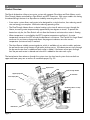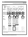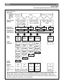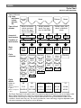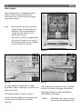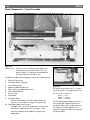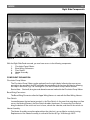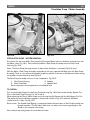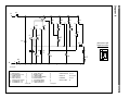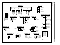
1
FOR MODELS:
SHI
4302
6802
6806
4306
6805
BOSCH
Dishwasher Repair Manual
Effective: December 1, 1998
SHU
3002
3012
4002
4016
4026
4302
4312
5302
5305
5312
5315
6802
6806
3006
3016
4006
4022
4036
4306
4316
5304
5306
5314
5316
6805
4303
4803
SHV
BSH Home Appliances
2800 South 25th Avenue
Broadview, Illinois 60153
1st Edition/Rev. 0
Introduction
This Repair Manual is designed to assist you in the evaluation, diagnosis and repair of
the current SHI, SHU and SHV model dishwasher series. To better understand these
appliances, their operation and construction we suggest that you read this manual
thoroughly before attempting any repairs.
All information is current at the time of printing.
H
1
Table of Contents
Description
Page
Section 1 . . . . . . . . . . . . . . . . . . . . . . . . . . . . . . . . . . . . . . . . . . . . . . . . . . . . . . . . . . . . . . . 3
Warranty / Technical Specifications . . . . . . . . . . . . . . . . . . . . . . . . . . . . . . . . . . . . . . . . . . . . . . . . . 4
Model / Serial Number Location . . . . . . . . . . . . . . . . . . . . . . . . . . . . . . . . . . . . . . . . . . . . . . . . . . . . 5
Product Overview . . . . . . . . . . . . . . . . . . . . . . . . . . . . . . . . . . . . . . . . . . . . . . . . . . . . . . . . . . . . . 6 – 7
Notes . . . . . . . . . . . . . . . . . . . . . . . . . . . . . . . . . . . . . . . . . . . . . . . . . . . . . . . . . . . . . . . . . . . . . . . . . . 8
Section 2 . . . . . . . . . . . . . . . . . . . . . . . . . . . . . . . . . . . . . . . . . . . . . . . . . . . . . . . . . . . . . . . 9
Operation, SHU 3002 / 3006 / 3012 / 3016 / 4002 / 4006 / 4016 / 4022 / 4026 / 4036 .
Cycle Chart . . . . . . . . . . . . . . . . . . . . . . . . . . . . . . . . . . . . . . . . . . . . . . . . . . . . . . . . . . . . . . . . . . . .
Operation, SHI 4302 / 4306 — SHU 4302 / 4306 / 4312 / 4316 . . . . . . . . . . . . . . . . . . . . . .
Cycle Chart . . . . . . . . . . . . . . . . . . . . . . . . . . . . . . . . . . . . . . . . . . . . . . . . . . . . . . . . . . . . . . . . . . . .
Operation, SHU 5302 / 5304 / 5305 / 5306 / 5312 / 5314 / 5315 / 5316 . . . . . . . . . . . . . .
Cycle Chart . . . . . . . . . . . . . . . . . . . . . . . . . . . . . . . . . . . . . . . . . . . . . . . . . . . . . . . . . . . . . . . . . . . .
Operation, SHI / SHU 6802 / 6805 / 6806 . . . . . . . . . . . . . . . . . . . . . . . . . . . . . . . . . . . . . . . . .
Cycle Chart . . . . . . . . . . . . . . . . . . . . . . . . . . . . . . . . . . . . . . . . . . . . . . . . . . . . . . . . . . . . . . . . . . . .
Notes . . . . . . . . . . . . . . . . . . . . . . . . . . . . . . . . . . . . . . . . . . . . . . . . . . . . . . . . . . . . . . . . . . . . . . . . .
10
11
12
13
14
15
16
17
18
Section 3 . . . . . . . . . . . . . . . . . . . . . . . . . . . . . . . . . . . . . . . . . . . . . . . . . . . . . . . . . . . . . . 19
Rack System . . . . . . . . . . . . . . . . . . . . . . . . . . . . . . . . . . . . . . . . . . . . . . . . . . . . . . . . . . . . . . 20 – 21
Interior Features . . . . . . . . . . . . . . . . . . . . . . . . . . . . . . . . . . . . . . . . . . . . . . . . . . . . . . . . . . . 22 – 25
Detergent / Rinse-Agent Dispenser . . . . . . . . . . . . . . . . . . . . . . . . . . . . . . . . . . . . . . . . . . . . . . . . 26
Washability / Drying . . . . . . . . . . . . . . . . . . . . . . . . . . . . . . . . . . . . . . . . . . . . . . . . . . . . . . . . . . . . . 27
SERVICE REMINDER . . . . . . . . . . . . . . . . . . . . . . . . . . . . . . . . . . . . . . . . . . . . . . . . . . . 28
Section 4 . . . . . . . . . . . . . . . . . . . . . . . . . . . . . . . . . . . . . . . . . . . . . . . . . . . . . . . . . . . . . . 29
Outer Door Removal . . . . . . . . . . . . . . . . . . . . . . . . . . . . . . . . . . . . . . . . . . . . . . . . . . . . . . . . . . . . 30
Door Components . . . . . . . . . . . . . . . . . . . . . . . . . . . . . . . . . . . . . . . . . . . . . . . . . . . . . . . . . . . . . . 31
Dispenser Operation . . . . . . . . . . . . . . . . . . . . . . . . . . . . . . . . . . . . . . . . . . . . . . . . . . . . . . . . . . . . 32
Dispenser Removal . . . . . . . . . . . . . . . . . . . . . . . . . . . . . . . . . . . . . . . . . . . . . . . . . . . . . . . . . . . . . . 33
Facia Assembly . . . . . . . . . . . . . . . . . . . . . . . . . . . . . . . . . . . . . . . . . . . . . . . . . . . . . . . . . . . . 34 – 35
Notes . . . . . . . . . . . . . . . . . . . . . . . . . . . . . . . . . . . . . . . . . . . . . . . . . . . . . . . . . . . . . . . . . . . . . . . . . 36
Section 5 . . . . . . . . . . . . . . . . . . . . . . . . . . . . . . . . . . . . . . . . . . . . . . . . . . . . . . . . . . . . . . 37
Base Components – Front Accessible: Electrical Connection . . . . . . . . . . . . . . . . . . . . . . . . . 38
Circulation Motor Capacitor . . . . . . . . . . . . . . . . . . . . 38
Leveling Legs . . . . . . . . . . . . . . . . . . . . . . . . . . . . . . . . 39
Water Valve . . . . . . . . . . . . . . . . . . . . . . . . . . . . . . . . . 39
Drain Motor . . . . . . . . . . . . . . . . . . . . . . . . . . . . . 40 — 41
H
2
Table of Contents
SERVICE REMINDER . . . . . . . . . . . . . . . . . . . . . . . . . . . . . . . . . . . . . . . . . . . . . . . . . . . 42
Description
Page
Section 6 . . . . . . . . . . . . . . . . . . . . . . . . . . . . . . . . . . . . . . . . . . . . . . . . . . . . . . . . . . . . . . 43
Left Side Access . . . . . . . . . . . . . . . . . . . . . . . . . . . . . . . . . . . . . . . . . . . . . . . . . . . . . . . . . . . . . . . 44
Left Side Components . . . . . . . . . . . . . . . . . . . . . . . . . . . . . . . . . . . . . . . . . . . . . . . . . . . . . . . . . . . 45
Water Inlet / Discharge System – Operation . . . . . . . . . . . . . . . . . . . . . . . . . . . . . . . . . . . . .46 – 47
Water Inlet / Discharge System – Removal . . . . . . . . . . . . . . . . . . . . . . . . . . . . . . . . . . . . . . . . . . 48
Section 7 . . . . . . . . . . . . . . . . . . . . . . . . . . . . . . . . . . . . . . . . . . . . . . . . . . . . . . . . . . . . . . 49
Right Side Access . . . . . . . . . . . . . . . . . . . . . . . . . . . . . . . . . . . . . . . . . . . . . . . . . . . . . . . . . . . . . . 50
Right Side Components . . . . . . . . . . . . . . . . . . . . . . . . . . . . . . . . . . . . . . . . . . . . . . . . . . . . . . . . . 51
NTC Operation . . . . . . . . . . . . . . . . . . . . . . . . . . . . . . . . . . . . . . . . . . . . . . . . . . . . . . . . . . . . . . . . . 52
NTC Removal . . . . . . . . . . . . . . . . . . . . . . . . . . . . . . . . . . . . . . . . . . . . . . . . . . . . . . . . . . . . . .53 – 57
Notes . . . . . . . . . . . . . . . . . . . . . . . . . . . . . . . . . . . . . . . . . . . . . . . . . . . . . . . . . . . . . . . . . . . . . . . . . 58
Section 8 . . . . . . . . . . . . . . . . . . . . . . . . . . . . . . . . . . . . . . . . . . . . . . . . . . . . . . . . . . . . . . 59
Tank Removal . . . . . . . . . . . . . . . . . . . . . . . . . . . . . . . . . . . . . . . . . . . . . . . . . . . . . . . . . . . . . 60 – 62
Base Components . . . . . . . . . . . . . . . . . . . . . . . . . . . . . . . . . . . . . . . . . . . . . . . . . . . . . . . . . . . . . . 63
Circulation Pump / Motor Removal . . . . . . . . . . . . . . . . . . . . . . . . . . . . . . . . . . . . . . . . . . . . . . . . . 64
Circulation Pump / Motor Assembly . . . . . . . . . . . . . . . . . . . . . . . . . . . . . . . . . . . . . . . . . . . . . . . . 65
Heater Assembly Removal . . . . . . . . . . . . . . . . . . . . . . . . . . . . . . . . . . . . . . . . . . . . . . . . . . . . . . . . 66
Heater Assembly . . . . . . . . . . . . . . . . . . . . . . . . . . . . . . . . . . . . . . . . . . . . . . . . . . . . . . . . . . . . . . . 67
Aqua Sensor . . . . . . . . . . . . . . . . . . . . . . . . . . . . . . . . . . . . . . . . . . . . . . . . . . . . . . . . . . . . . . . . . . . 68
Door Spring Removal . . . . . . . . . . . . . . . . . . . . . . . . . . . . . . . . . . . . . . . . . . . . . . . . . . . . . . . . . . . . 69
Notes . . . . . . . . . . . . . . . . . . . . . . . . . . . . . . . . . . . . . . . . . . . . . . . . . . . . . . . . . . . . . . . . . . . . . . . . . 70
Section 9 . . . . . . . . . . . . . . . . . . . . . . . . . . . . . . . . . . . . . . . . . . . . . . . . . . . . . . . . . . . . . . 71
Wiring Diagrams / Schematics . . . . . . . . . . . . . . . . . . . . . . . . . . . . . . . . . . . . . . . . . . . . . . . .72 – 84
Test Program . . . . . . . . . . . . . . . . . . . . . . . . . . . . . . . . . . . . . . . . . . . . . . . . . . . . . Diagram 1
SHI
SHI
SHU
SHU
SHU
SHU
SHU
SHV
4302 /
6802 /
3002 /
4002 /
4302 /
5302 /
6802 /
4303 /
4306 . . . . . . . . . . . . . . . . . . . . . . . . . . . . . . . . . . . . . . . . . . . . . . . .
6805 / 6806 . . . . . . . . . . . . . . . . . . . . . . . . . . . . . . . . . . . . . . . . .
3006 / 3012 / 3016 . . . . . . . . . . . . . . . . . . . . . . . . . . . . . . . . . . .
4006 / 4016 / 4022 / 4026 / 4036 . . . . . . . . . . . . . . . . . . . . . .
4306 / 4312 / 4316 . . . . . . . . . . . . . . . . . . . . . . . . . . . . . . . . . . .
5304 / 5305 / 5306 / 5312 / 5314 / 5315 / 5316 . . . . . . . . .
6805 / 6806 . . . . . . . . . . . . . . . . . . . . . . . . . . . . . . . . . . . . . . . . .
4803 . . . . . . . . . . . . . . . . . . . . . . . . . . . . . . . . . . . . . . . . . . . . . . . .
Diagrams
Diagrams
Diagrams
Diagrams
Diagrams
Diagrams
Diagrams
Diagrams
1, 8, 9
1, 8, 11
2, 3, 4
5, 6, 7
1, 8, 9
1, 8, 10
1, 8, 11
12, 13
H
3
Section 1
Description
Page
Warranty / Technical Specifications . . . . . . . . . . . . . . . . . . . . . . . . . . . . . . . . . . . . . . . . . . . . . . . . . 4
Model / Serial Number Location . . . . . . . . . . . . . . . . . . . . . . . . . . . . . . . . . . . . . . . . . . . . . . . . . . . . 5
Product Overview . . . . . . . . . . . . . . . . . . . . . . . . . . . . . . . . . . . . . . . . . . . . . . . . . . . . . . . . . . . . . 6 – 7
Notes . . . . . . . . . . . . . . . . . . . . . . . . . . . . . . . . . . . . . . . . . . . . . . . . . . . . . . . . . . . . . . . . . . . . . . . . . . 8
H
4
Warranty / Technical Specifications
Warranty
1st Year
2nd Year
3rd – 5th Year
3rd – 5th Year
Parts & Labor.
Parts only.
Electronic Boards, parts only.
Racks, parts only.
This does not include rack wheels; silverware baskets or plastic shelving.
Lifetime Stainless Steel.
Must receive a special authorization before attempting any repairs or replacement.
Cosmetic items, Facia and Door Panels are only warranted against manufacturing defects. In the event of a scratch or
dent have the customer contact the Customer Service Department.
CUSTOMER SERVICE 800-944-2904
TECHNICAL SERVICE 888-522-6724
Technical Specifications
Electrical Requirements
Rating
Dedicated Circuit
Total Amps (load rated)
120V / 60Hz
15 Amp
11 Amp
Water Supply
Suggested Incoming Temp.
PSI Min / Max
Water Connection
Component Values
Component
Water Valve
Drain Motor
Circulation Motor
NTC
PTC (actuator)
Heater
140° f
20 / 60
3/8” Copper or Flexible Stainless Steel
Ohms*
1K
16
10
55K at room temp.
(75° f)
200
10.5
Amperage
—
.75
1.25
—
—
9.75
Other
—
—
—
Resistance decreases as
temperature increases
—
1200 watts
*always disconnect both component leads before measuring for resistance.
Electrical Warning:
To avoid personal injury and/or property damage it is important that safe servicing practices and procedures are observed at
all times. Disconnect the electrical service before attempting any repairs, and live tests are to be performed by experienced
and qualified service personnel only.
H
5
Model / Serial Number Location
Fig. 1-1
Fig. 1-2
Located on the right hand side of the Inner Door is the Model and Serial number tag, Fig. 1-1.
The Model and Serial numbers can be found on the left side of the tag within the black outline box, Fig. 1-2.
The Model Number for this unit is SHU 5312 UC/U06.
Located just under the Model Number is the ten-digit Serial Number.
The Serial Number for this unit is FD 7801 123456.
Service note: A second Model and Serial number tag is located on the Base, see Section 5, Fig. 10-1.
H
6
Product Overview
The Bosch dishwasher utilizes a two motor system with separate Circulation and Drain Motors, and a
Flow Through Heater controlled by a Flow Switch and NTC Thermistor. With some models also having
the advanced logic feature of an Aqua Sensor turbidity measuring devise, Fig. 2-1.
• A two motor system allows each motor to be designed for a single function, thus reducing overall
size and energy consumption. While also reducing operating noise.
• The Flow-Through Heater allows a shorter heating cycle since all water must pass through the
Heater, increasing water temperature by approximately two degrees a minute. To protect the
heater from dry fire, the Flow Switch will not allow the Heater to activate unless water is flowing.
• Water temperature is controlled by the NTC (negative temperature coefficient). As water
temperature increases the NTC records the decrease in resistance. The Control Unit Logic Board
measures this resistance change and allows the program to advance once the correct
temperature (resistance level) is reached.
• The Aqua Sensor turbidity measuring device, which is available only on select models, evaluates
the pre-wash water using a beam of light and a pick-up sensor. If the beam passes easily through
the pre-wash water then no additional wash water is added. If the beam cannot pass through,
then the pre-wash water is drained and a fresh fill is added for the main wash cycle.
The heated water then advances through the system via a four level wash system that uses both an
upper and lower spray arm as well as an overhead sprayer, Fig. 2-2.
Aqua Sensor
NTC
Flow Through Heater
Upper Spray Arm
Flow Switch
Lower Spray Arm
Circulation Motor / Pump
Impeller Cover
Drain Motor
Fig. 2-1
H
7
Product Overview
Overhead Spray
Coupling
Upper Spray Arm
Feed Tube
Lower Spray Arm
Aqua Sensor
Sump
Fig. 2-2
Flow Through
Heater
H
8
Notes
H
9
Section 2
Description
Page
Operation, SHU 3002 / 3006 / 3012 / 3016 / 4002 / 4006 / 4016 / 4022 / 4026 / 4036 . 10
Cycle Chart . . . . . . . . . . . . . . . . . . . . . . . . . . . . . . . . . . . . . . . . . . . . . . . . . . . . . . . . . . . . . . . . . . . . 11
Operation, SHI 4302 / 4306
SHU 4302 / 4306 / 4312 / 4316 . . . . . . . . . . . . . . . . . . . . . . . . . . . . . . . . . . . . . . . 12
Cycle Chart . . . . . . . . . . . . . . . . . . . . . . . . . . . . . . . . . . . . . . . . . . . . . . . . . . . . . . . . . . . . . . . . . . . . 13
Operation, SHU 5302 / 5304 / 5305 / 5306 / 5312 / 5314 / 5315 / 5316 . . . . . . . . . . . . . . 14
Cycle Chart . . . . . . . . . . . . . . . . . . . . . . . . . . . . . . . . . . . . . . . . . . . . . . . . . . . . . . . . . . . . . . . . . . . . 15
Operation, SHI & SHU 6802 / 6805 / 6806 . . . . . . . . . . . . . . . . . . . . . . . . . . . . . . . . . . . . . . . . 16
Cycle Chart . . . . . . . . . . . . . . . . . . . . . . . . . . . . . . . . . . . . . . . . . . . . . . . . . . . . . . . . . . . . . . . . . . . . 17
Notes . . . . . . . . . . . . . . . . . . . . . . . . . . . . . . . . . . . . . . . . . . . . . . . . . . . . . . . . . . . . . . . . . . . . . . . . . 18
H
10
Operation
SHU 3002/3006/3012/3016/4002/4006/4016/4022/4026/4036
Fig. 3-1
Fig. 3-2
The SHU 30** and 40** are both mechanical units that operate using a basic Timer and Selector Switch.
TO OPERATE EITHER MODEL, (a SHU 4006 is shown):
Fig. 3-2.
First select a cycle by pushing the corresponding Cycle Button in. The Cycle Button remains in
the indented position until another cycle is chosen.
Now, depress the On/Off Button until it locks in place and the On LED illuminates.
Note:
The On lamp will remain illuminated until the On/Off Button is depressed a second time
turning the unit off.
If the door is opened during the cycle, the On/Off Button will be reset to off and must
again be depressed to re-active the unit.
Fig. 3-1.
Then, turn the Timer Knob slowly clockwise to the start position and release. You will hear the
Drain Motor activate.
The Timer Knob will continue to advance clockwise back to the twelve O’clock position until the
cycle is complete.
Please note: During the Rinse & Hold Cycle the Timer Knob will only advance to the two O’clock
position and then stop, indicating the end of the Rinse & Hold cycle.
H
11
Cycle Chart
SHU 3002/3006/3012/3016/4002/4006/4016/4022/4026/4036
Type of dishware
e.g. china,
pots/pans,
Non-delicutlery,
cate
glasses,
etc.
Mixed
Type of food
remains
Soups, casseroles,
sauces, potatoes,
pasta, rice, eggs,
roast or fried food
Amount of
food remains
a lot
Condition of
food remains
stuck on hard
Wash
cycle
Cycle
sequence
Delicate
Mixed
Soups, potatoes,
pasta, rice, eggs,
roast or fried food
Coffee, cakes, milk,
salami, cold drinks,
salads
a lot
a little
a little
very little
loosely attached
Power
Scrub
Regular
Wash
Delicate
Wash
Rinse
& Hold
Pre-rinse
Pre-rinse
Pre-rinse
Pre-rinse
Pre-wash
Pre-wash
Wash
140˚F
Wash
161˚F
Wash
140˚F
Rinse
Rinse
Rinse
Rinse-aid
161˚F
Rinse-aid
161˚F
Rinse-aid
161˚F
Drying
Drying
Drying
85
78
70
10
6.55
6.55
5.36
1.19
24.75
24.75
20.25
4.5
Cycle
details
Duration in
minutes
Water consumption
in gallons
Water consumption
in liters
Shown above are the range of values that may be obtained while running the dishwasher under normal
conditions. Actual values may vary. The actual cycle duration, water and energy usage are dependent upon
inlet water temperature.
Delicate cycle not used on SHU 3002/3006/3012/3016
H
12
Operation
SHI 4302/4306
SHU 4302/4306/4312/4316
Fig. 3-3
Fig. 3-4
The SHI or SHU 43** series operates using an electronic Control Unit.
TO OPERATE:
Fig. 3-3.
First depress the On/Off Button until it locks in place.
Fig. 3-4.
Once the On/Off Button is depressed the LED above the previously used cycle will illuminate.
To change the cycle, simply press the desired Cycle Button twice. The LED above that cycle will
then illuminate.
As the program advances the Cycle Progress LED’s will illuminate (wash, rinse / dry). When the
cycle is complete the Clean LED will be illuminated.
TO CANCEL A CYCLE:
Press the Power Scrub Plus and Regular Wash Buttons both in at the same time. The unit will
then drain and the Clean LED will illuminate.
Please note: If the door is opened during the cycle, the On/Off Button will be reset to off andmust
be depressed again to re-active the cycle. The cycle will resume from where it left off.
H
13
Cycle Chart
SHI 4302/4306
Type of dishware
e.g. china,
pots/pans,
Non-delicutlery,
cate
glasses,
etc.
Mixed
Type of food
remains
Soups, casseroles,
sauces, potatoes,
pasta, rice, eggs,
roast or fried food
Amount of
food remains
a lot
Condition of
food remains
stuck on hard
Wash
cycle
Cycle
sequence
Duration in
minutes
Water consumption
in gallons
Water consumption
in liters
Delicate
Mixed
Soups, potatoes,
pasta, rice, eggs,
roast or fried food
Coffee, cakes, milk,
salami, cold drinks,
salads
a lot
a little
a little
very little
loosely attached
Power
Scrub
Plus
Scrub
Wash
Regular
Wash
Rinse
& Hold
Pre-rinse
Pre-rinse
Pre-rinse
Pre-rinse
Pre-wash
125˚F
Wash
150˚F
Wash
140˚F
Wash
161˚F
First Rinse
Rinse
First Rinse
Second
Rinse
Rinse-aid
161˚F
Rinse-aid
161˚F
Second
Rinse
Rinse-aid
161˚F
Cycle
details
SHU 4302/4306/4312/4316
Drying
Drying
Drying
99
85
80
10
7.1
6
5.4
1.2
26.9
22.7
20.4
4.5
Shown above are the range of values that may be obtained while running the dishwasher under normal
conditions. Actual values may vary. The actual cycle duration, water and energy usage are dependent upon
inlet water temperature.
H
14
Operation
SHU 5302/5304/5305/5306/5312/5314/5315/5316
Fig. 3-5
Fig. 3-6
The SHU 53** series operates using an electronic Control Unit.
TO OPERATE:
Fig. 3-5.
First depress the On/Off Button until it locks in place.
Fig. 3-6.
Once the On/Off Button is depressed the LED above the previously used cycle will illuminate. To change the cycle, simply press
the desired Cycle Button twice. The LED above that cycle will then illuminate.
The Cycle Countdown will display an approximate run time for the cycle chosen. This run time will depend on incoming water
temperature and the turbidity of the pre-wash water.
Note:
It is normal for the Countdown Display to remain at a time increment for more than one minute, or skip a time increment
depending on the calculations of the Control Unit.
Also, with continued use the Control Unit will learn the wash and temperature patterns for the most commonly used
programs and will then reduce the overall start and running times.
At the end of the cycle the display will show a CL, indicating that the cycle is complete.
TO CANCEL A CYCLE:
Press the Scrub Wash and Delicate / Econo Buttons both in at the same time. The unit will then drain and the figure CL will
appear in the display.
DELAY START:
The Delay Start feature allows the unit to be delayed for up to nine hours. To program, start the unit as described above, but
after selecting a cycle push the Delay Start button. The display will show a 1h, or one-hour delay. Continue to depress the
Delay Start Button until the desired delay time is reached (up to nine hours, 9h).
The unit will begin automatically once the delay time has elapsed. To reset the delay, press the Delay Start Button until it reaches 0h.
REFILL RINSE AGENT LED:
The Refill Rinse Agent LED is activated via a Reed Switch on the Detergent Dispenser, Section 4, Fig. 8-3. The LED will
illuminate when the Rinse Agent Dispenser is empty.
Service note:
The Refill Rinse Agent LED will also illuminate when the dishwasher door is opened and then
closed even if the Dispenser is full, but will only remain lit for a few seconds.
“F” CODE:
An “F” in the display window indicates a filling fault, see Section 6, Fig. 12-1 through Fig.12-6.
Please note:
If the door is opened during the cycle, the On/Off Button will be reset to off and must be depressed again
to re-active the cycle. The cycle will resume from where it left off.
H
15
Cycle Chart
SHU 5302/5304/5305/5306/5312/5314/5315/5316
Type of dishware
e.g. china,
pots/pans,
Non-delicutlery,
cate
glasses,
etc.
Mixed
Type of food
remains
Soups, casseroles,
sauces, potatoes,
pasta, rice, eggs,
roast or fried food
Amount of
food remains
a lot
Condition of
food remains
stuck on hard
Wash
cycle
Cycle
sequence
Duration in
minutes
Water consumption
in gallons
Water consumption
in liters
Mixed
Soups, potatoes,
pasta, rice, eggs,
roast or fried food
Coffee, cakes, milk,
salami, cold drinks,
salads
a lot
a little
a little
very little
loosely attached
Power
Scrub
Plus
Scrub
Wash
Regular
Wash
Delicate/
Economy
Rinse
& Hold
Pre-rinse
Pre-rinse
Pre-rinse
Pre-rinse
Pre-wash
125˚F
Wash
140˚F
Wash
150˚F
Wash
140˚F
Rinse
Wash
161˚F
First Rinse
Rinse
Rinse-aid
155˚F
First Rinse
Second
Rinse
Rinse-aid
161˚F
Rinse-aid
161˚F
Second
Rinse
Rinse-aid
161˚F
Cycle
details
Delicate
Drying
Drying
Drying
Drying
99
85
80
70
10
7.1/5
6/4.2
5.4/3.8
3.6/2.5
1.2/0.8
26.9/18.9
22.7/15.9
20.4/14.4
13.5/9.5
4.5/3.2
The Bosch Sensotronic™ will reduce water consumption by approximately 20%, in the case of lightly soiled
dishes. When Top Rack Only™ feature is used the water consumption is reduced approximately 30%.
Shown above are the range of values that may be obtained while running the dishwasher under normal
conditions. Actual values may vary. The actual cycle duration, water and energy usage are dependent upon
inlet water temperature and amount of soil on dishware.
H
16
Operation
SHI/SHU 6802/6805/6806
Fig. 3-7
Fig. 3-8
The SHI / SHU 68** series operates using an electronic Control Unit.
TO OPERATE:
Fig. 3-7.
First depress the On/Off Button until it locks in place.
Fig. 3-8.
Once the On/Off Button is depressed the LED above the previously used cycle will illuminate. To change the cycle, simply press
the desired Cycle Button twice. The LED above that cycle will then illuminate.
The Cycle Countdown will display an approximate run time for the cycle chosen. This run time will depend on incoming water
temperature and the turbidity of the pre-wash water.
Note:
It is normal for the Countdown Display to remain at a time increment for more than one minute, or skip a time increment
depending on the calculations of the Control Unit.
Also, with continued use the Control Unit will learn the wash and temperature patterns for the most commonly used
programs and will then reduce the overall start and running times.
At the end of the cycle the display will show a CL, indicating that the cycle is complete.
TO CANCEL A CYCLE:
Press the Scrub Wash and Delicate / Econo Buttons both in at the same time. The unit will then drain and the figure CL will
appear in the display.
DELAY START:
The Delay Start feature allows the unit to be delayed for up to nine hours. To program, start the unit as described above, but
after selecting a cycle push the Delay Start button. The display will show a 1h, or one-hour delay. Continue to depress the
Delay Start Button until the desired delay time is reached (up to nine hours, 9h).
The unit will begin automatically once the delay time has elapsed. To reset the delay, press the Delay Start Button until it reaches 0h.
TOP RACK ONLY:
The Top Rack Only feature can be used in conjunction with any cycle. To active, press the Top Rack Only Button after selecting a
cycle, the Top Rack Only LED will illuminate and all water will be diverted to the upper wash arm for the complete cycle.
REFILL RINSE AGENT LED:
The Refill Rinse Agent LED is activated via a Reed Switch on the Detergent Dispenser, Section 4, Fig. 8-3. The LED will
illuminate when the Rinse Agent Dispenser is empty.
Service note:
The Refill Rinse Agent LED will also illuminate when the dishwasher door is opened and then
closed even if the Dispenser is full, but will only remain lit for a few seconds.
“F” CODE:
An “F” in the display window indicates a filling fault, see Section 6, Fig. 12-1 through Fig.12-6.
Please note:
If the door is opened during the cycle, the On/Off Button will be reset to off and must be depressed again
to re-active the cycle. The cycle will resume from where it left off.
H
17
Cycle Chart
SHI/SHU 6802/6805/6806
Type of dishware
e.g. china,
pots/pans,
Non-delicutlery,
cate
glasses,
etc.
Mixed
Type of food
remains
Soups, casseroles,
sauces, potatoes,
pasta, rice, eggs,
roast or fried food
Amount of
food remains
a lot
Condition of
food remains
stuck on hard
Wash
cycle
Cycle
sequence
Duration in
minutes
Water consumption
in gallons
Water consumption
in liters
Mixed
Soups, potatoes,
pasta, rice, eggs,
roast or fried food
Coffee, cakes, milk,
salami, cold drinks,
salads
a lot
a little
a little
very little
loosely attached
Power
Scrub
Plus
Scrub
Wash
Regular
Wash
Delicate/
Economy
Quick
Wash
Rinse
& Hold
Pre-rinse
Pre-rinse
Pre-rinse
Wash
104˚F
Pre-rinse
Pre-wash
125˚F
Wash
140˚F
Wash
150˚F
Wash
140˚F
Rinse
Rinse
Wash
161˚F
First Rinse
Rinse
Rinse-aid
155˚F
Rinse-aid
140˚F
First Rinse
Second
Rinse
Rinse-aid
161˚F
Rinse-aid
161˚F
Drying
Drying
Second
Rinse
Rinse-aid
161˚F
Cycle
details
Delicate
Drying
Drying
Drying
99
85
80
70
30
10
7.1/5
6/4.2
5.4/3.8
3.6/2.5
2.7/1.9
1.2/0.8
26.9/18.9
22.7/15.9
20.4/14.4
13.5/9.5
10.5/7.4
4.5/3.2
The Bosch Sensotronic™ will reduce water consumption by approximately 20%, in the case of lightly soiled
dishes. When Top Rack Only™ feature is used the water consumption is reduced approximately 30%.
Shown above are the range of values that may be obtained while running the dishwasher under normal
conditions. Actual values may vary. The actual cycle duration, water and energy usage are dependent upon
inlet water temperature and amount of soil on dishware.
H
18
Notes
H
19
Section 3
Description
Page
Rack System . . . . . . . . . . . . . . . . . . . . . . . . . . . . . . . . . . . . . . . . . . . . . . . . . . . . . . . . . . . . . . 20 – 21
Interior Features . . . . . . . . . . . . . . . . . . . . . . . . . . . . . . . . . . . . . . . . . . . . . . . . . . . . . . . . . . . 22 – 25
Detergent / Rinse-Agent Dispenser . . . . . . . . . . . . . . . . . . . . . . . . . . . . . . . . . . . . . . . . . . . . . . . . 26
Washability / Drying . . . . . . . . . . . . . . . . . . . . . . . . . . . . . . . . . . . . . . . . . . . . . . . . . . . . . . . . . . . . . 27
Notes . . . . . . . . . . . . . . . . . . . . . . . . . . . . . . . . . . . . . . . . . . . . . . . . . . . . . . . . . . . . . . . . . . . . . . . . . 28
H
20
Rack System
Rack configurations for individual dishwasher
models will vary. However, all Racks are
constructed from a steel wire grid with a gray
nylon outer covering.
Note:
Racks may discolor due to the water
supply or types of food remaining on
the dishes. We recommend that a
vinegar wash be used to assist in
removing these stains.
Start the unit, and let run approximately
ten minutes, then pour in two cups of
white vinegar and let the unit complete
the cycle, repeat if necessary.
Fig. 4-1
Fig. 4-2
Fig. 4-3
On select models the Upper Rack is height
adjustable. To adjust rack height, or to remove the
Rack from the unit.
With the Rack fully extended. Lift up on the Rack
until the Front Rollers disengage from the Rail.
Fully extend the Rack as shown in Fig. 4-2
Now bring the Rack out further and allow the
Rear Wheels to disengage.
Note how the Rack Rollers are designed to ride
on the outside of the Rails for a smoother
operation.
Rollers:
Rack Rollers are a press fit making
for easy removal and replacement.
H
21
Rack System
Fig. 4-4
Fig. 4-5
Attached to the Upper Rack is the Upper Spray Arm Assembly.
The Upper Spray Arm can be removed from the Upper Spray Arm Assembly for cleaning or
replacement by turning the Arm Nut counter-clockwise, Fig. 4-4.
And then bringing the Arm down and off the Arm Assembly, Fig. 4-5.
H
22
Interior Features
1
2
2
7
3
4
6
5
Fig. 5-1
Interior features for all model dishwasher covered in this repair manual are identical. Those
features include:
1.
2.
3.
4.
5.
6.
7.
Strike Plate. The Strike Plate is in a fixed position and cannot be adjusted.
Upper Rack Rails and Guide Rollers.
Door Gasket
Lower Spray Arm
Filter Basket
Filter Screen
Feeder Tube Assembly
H
23
Interior Features
Fig. 5-2
The Upper Rack Rails are made
of stainless steel with a plastic
end cap.
Fig. 5-3
To remove the Rail, disengage
the End Cap by applying
outward pressure to the Cap’s
top tab, unclipping it from the
Rail. Then slide the Rail out from
the Guide Rollers.
Fig. 5-4
The Upper Rack Guide Rollers
are permanently attached to the
Tank and cannot be removed or
repaired.
Fig. 5-5
The Door Gasket is press fit into a channel
molded around the Tank.
Fig. 5-6
To remove the Gasket, simply pull it away from the
Tank Channel.
Note: Two inches of overlap are left at each end
of the Gasket to insure a proper seal.
To replace, press the ribbed end firmly into the
channel until secure. No sealant or glue is required.
Service tip:
To test for a bad Door Gasket, open the dishwasher door and insert a dollar bill, then
close the door and pull the bill out. If the bill is snug the Gasket is good, if the bill slides
out easily the Door Gasket may need to be replaced.
H
24
Interior Features
Water
Level
Fig. 5-7
Fig. 5-8
Fig. 5-9
Fig. 5-10
2
1
Fig. 5-11
Fig. 5-12
2
H
25
Interior Features
Fig. 5-7
The operating water level of the dishwasher is at approximately the upper edge of the filter basket.
Fig. 5-8
The Lower Spray Arm is press fit into the Feeder Tube Socket.
To remove the Arm, grasp the Arm Hub and pull up until the Arm disengages from the Socket.
The Arm or Arm Socket can now be checked for debris.
Fig. 5-9
The Filter Basket is removed by turning it ninety degrees counter-clockwise.
Fig. 5-10 Then lift it out for cleaning.
The Filter is a fine mesh of stainless steel and should be inspected and cleaned at least
once a month.
Fig. 5-11 With the Filter Basket removed, the filter screen can then be lifted out.
The Filter Screen is also made of stainless steel, and was designed with rolled ends to
eliminate sharp edges. It too should be inspected and cleaned at least once a month.
Fig. 5-12 With the Filter Screens removed you now have access to the sump area.
The Sump has a Drain Intake on the left, and the Circulation Pump Intake on the right.
A removable cover, item 1, hides the Drain Impeller. To remove the cover, remove the single
T-20 Torx screw and then lift the cover off. You may now examine the Impeller for any
obstructions.
The Feeder Tube Assembly allows water to flow to the Lower, then Upper Spray Arms and
then to the Top Sprayer Head. It is replaced as a complete assembly by first removing the
two T-20 Torx screws, item 2, at its base.
Then bring the tube up and off the Sump Housing, and remove it from the retaining clip
located on the rear wall.
H
26
Detergent / Rinse-Agent Dispenser
Located on the Inner Door is the Detergent / Rinse
Agent Dispenser, Fig. 6-1.
The Dispenser Housing is one assembly containing
three individual components.
Rinse Agent Dispenser.
Detergent Cup.
Steam Vent.
Note: Mechanical operation and removal of the
Dispenser is shown in Section 4.
Fig. 6-1
To fill or adjust the Rinse Agent Dispenser, open
the Rinse Agent Door by pulling up on the Door
Latch.
1
The Dosage Meter, item 1, is now visible. The
Dosage Meter allows you to adjust the amount of
Rinse Agent dispensed into the rinse stage of the
cycle. The factory setting is three.
2
1
2
There is also an eyepiece, item 2, that provides a
visual indication as to the amount of Rinse Agent
remaining in the Dispenser.
Fig. 6-2
To the right of the Rinse Agent Dispenser is the
Detergent Cup, item 1.
2
Once detergent has been loaded into the cup, slide
the Detergent Door, item 2, closed.
1
When the door is fully closed press down on the
door end to lock it.
Fig. 6-3
2
1
Fig. 6-4
A white Locking Lever, item 1, will then extend.
Once closed, the detergent door may be released
by pressing in on the Locking Lever.
With the Detergent Door closed the Steam Vent is
now visible, item 2.
During the drying stage of the cycle, steam is
drawn through the vent and collects in a
Condensation Tube.
H
27
Washability / Drying
WASHABILITY
There are four factors that play a critical role in Washability: Time, Temperature, Water and Detergent. It
is important when attempting to determine the cause of a Washability complaint that all four factors be
considered and tested.
Time:
The duration of the program is accurate (see cycle chart).
Temperature: The wash and rinse temperatures are within the desired range (see cycle chart).
Water:
The unit is filling with the correct amount of water (Section 3, Fig.5-7)
Detergent:
The detergent is fresh, and not being used in excessive amounts.
Please note: Other factors such as clean filters, a properly routed drain hose, water hardness and
quality, as well as loading of items will also effect Washability.
DRYING
As part of an energy saving design Bosch Dishwashers do not activate the Heating Element during the
Drying cycle. Instead, the dishwasher utilizes a rinse temperature of up to 161° Fahrenheit, and the
addition of Rinse Agent to achieve a quality drying result.
HOW THIS SYSTEM FUNCTIONS:
During the rinse cycle water is heated to 161° Fahrenheit, this heat is transferred to the items in
the dishwasher where it is absorb and stored.
During the drying portion of the cycle all dishwasher items will then radiate the stored heat, thus
evaporating any water that has collected on the items surface, burning it off and converting the
liquid into steam.
This process of “flash drying” is assisted by the release of Rinse Agent into the rinse water. Rinse
Agent is a water softener that inhibits water from collecting or pooling, allowing it to be easily
evaporated.
The remaining steam is vented from the interior through the Steam Vent (Fig. 6-4, item 2) where it
is then collected by, and drained from the Condensation Tube (Section 4, Fig. 7-5, item 2).
Service note: When confronted with a drying complaint, make sure the Rinse Agent Dispenser is full,
and the rinse water temperature is within the desired range. Please remember that the
unit will not dry without Rinse Agent.
H
28
Service Reminder
From this point in the manual only the technical features and components of the
SHU 5312 will be demonstrated.
However, due to the overwhelming similarities between the model SHU 5312 and the
remaining Bosch Dishwasher line, you will be able to easily diagnose and repair all
current Bosch model SHU, SHI and SHV Dishwashers.
H
29
Section 4
Description
Page
Outer Door Removal . . . . . . . . . . . . . . . . . . . . . . . . . . . . . . . . . . . . . . . . . . . . . . . . . . . . . . . . . . . . 30
Door Components . . . . . . . . . . . . . . . . . . . . . . . . . . . . . . . . . . . . . . . . . . . . . . . . . . . . . . . . . . . . . . 31
Dispenser Operation . . . . . . . . . . . . . . . . . . . . . . . . . . . . . . . . . . . . . . . . . . . . . . . . . . . . . . . . . . . . 32
Dispenser Removal . . . . . . . . . . . . . . . . . . . . . . . . . . . . . . . . . . . . . . . . . . . . . . . . . . . . . . . . . . . . . . 33
Facia Assembly . . . . . . . . . . . . . . . . . . . . . . . . . . . . . . . . . . . . . . . . . . . . . . . . . . . . . . . . . . . . 34 – 35
Notes . . . . . . . . . . . . . . . . . . . . . . . . . . . . . . . . . . . . . . . . . . . . . . . . . . . . . . . . . . . . . . . . . . . . . . . . . 36
H
30
Outer Door Removal
Fig. 7-1
Fig. 7-2
To remove the Outer Door, open the door and remove the
six T-20 Torx screws located three on each side of the Inner
Stainless Door, Fig. 7-1.
Return the door back to its upright position, and bring the
bottom of the Door Panel out toward you, then slide the top of
the panel down and out from under the Facia Panel, Fig. 7-2.
As the Outer Door is being removed, the left or right Door
Guards may shift or fall out of place, Fig. 7-3.
Fig. 7-3
To reposition them, slide them back in over the hinge, Fig. 7-4,
lining up the door guard square tab with the hinge lever
square notch.
Please note: Door Guards must be in place before
reinstalling the Door Panel. Door Guards are
not used on SHI or SHV models.
Fig. 7-4
H
31
Door Compoments
7
2
6
1
3
5
4
4
8
9
9
Fig. 7-5
Once the Outer Door has been removed the following components become visible.
1.
2.
3.
4.
5.
6.
7.
Dispenser Assembly
Condensation Tube
Upper Wiring Harness
Door Guards
Door Seal
Bituminious Insulation
Cloth Fiber Insulation
Also note the Toe Kick, item 8, and the Toe Kick Mounting Screws, item 9.
H
32
Dispenser Operation
2
1
Fig. 8-1
The Dispenser Assembly operates via a PTC
Actuator (wax motor), item 1.
When voltage is applied to the Actuator it
advances a Combination Lever, item 2.
Fig. 8-2
…and bring the Actuator out from the Dispenser.
Please note: The Combination Lever cannot be
replaced individually, but only as
part of a new Dispenser Assembly.
The Combination Lever allows the Soap Door to open,
and later in the cycle dispenses the Rinse Agent.
To remove the Actuator, first disconnect the
Wiring Connector. Then, using a small
screwdriver, release the locking tab….
1
2
Fig. 8-3
Fig. 8-4
When the Dispenser requires Rinse Agent a Magnetic Float, Fig. 8-3, item 1, will lower and draw the
contacts of a Reed Switch, Fig. 8-3, item 2, together. This completes the circuit, and activates the Refill
Rinse Agent LED located on the Facia Panel.
To remove the Reed Switch, first disconnect the Wiring Connector. Now, using a small screwdriver
push in on the Reed Switch Mounting Tab, Fig. 8-3.
As you push in on the mounting tab, use a needle-nose pliers to bring the switch down and out from the
Dispenser, Fig. 8-4.
H
33
Dispenser Removal
Fig. 8-5
Fig. 8-6
If required, the Dispenser Assembly can be replaced as a complete unit.
TO REMOVE:
First remove the:
Upper Rack (Section 3, Fig. 4-3).
Wiring Connectors for the PTC Actuator, Reed Switch and Condensation Tube.
The Condensation Tube is inserted into the right side of the Dispenser with a gasket
seal, and press fit along the right side of the Inner Stainless Steel Door.
To remove, first remove any securing tape or wire ties for both the Condensation Tube
and Upper Wiring Harness. Then, disengage the tube from the door by pulling it toward
you, and sliding the tube out from the Dispenser.
Now, using a broad tipped regular screwdriver spread the top and bottom metal positioning
strips away from the Dispenser, Fig. 8-5.
Then apply light pressure to the Dispenser, and break the seal between it and the Inner
Stainless Steel Door, Fig. 8-6.
TO INSTALL:
Clean the inner portion of the stainless steel door where the Dispenser Gasket will seat. Then
bend the positioning strips back into place, straightening them if necessary.
Now, insert the new Dispenser making sure the positioning strips fit snugly against the Dispenser
Body. The Dispenser Gasket will make a watertight seal so caulk or sealant is not required.
Replace the Condensation Tube, Wiring Connectors and Upper Rack.
H
34
Facia Assembly
IMPORTANT SERVICE NOTE:
The Facia Assembly cannot be
removed unless the Outer Door is
removed first.
See section 4, Fig. 7-1.
FACIA ASSEMBLY REMOVAL:
After removing the Outer Door, remove
the six T-20 Torx screws securing the
Facia Assembly to the Inner Stainless
door, Fig. 9-1.
Fig. 9-1
Fig. 9-2
Fig. 9-3
With the screws removed, bring the Facia
Assembly down cradling it so as not to scratch
the Facia Console.
Now remove the Wiring Connectors by pressing in
on the locking tabs of each connector, then sliding
the connector up and off from the Control Unit.
H
35
Facia Assembly
With the Facia Assembly removed from
the unit, it can be further separated into
two assemblies.
To separate, release the four locking
tabs and bring the Facia Frame up from
the Facia Console, Fig. 9-4.
Fig. 9-4
The Facia Frame houses three
components:
1
3
2
Item 1, On/Off Switch.
Item 2,Door Latch Assembly.
Item 3,Control Unit.
Note: The Facia Console or Program
Buttons can be replaced at this
time.
Fig. 9-5
ON/OFF SWITCH REMOVAL:
1
2
Bend the single tab up, item 1.
Then slide the switch up and out from
the frame, and remove the Locking
Lever, item 2.
Note: The Locking Lever, item 2,
switches the unit off when the
door is opened during operation.
Fig. 9-6
DOOR LATCH ASSEMBLY REMOVAL:
Bend the two tabs up and slide the
Latch down.
CONTROL UNIT REMOVAL:
Press in on the three locking tabs and
bring the Control Unit out from the
Console Frame.
Fig. 9-7
Note: Always reset the new Control Unit
by pressing the appropriate
cancellation buttons, see Section 2.
H
36
Notes
H
37
Section 5
Description
Base Components – Front Accessible:
Page
Electrical Connection . . . . . . . . . . . . . . . . . . . . . . . . . 38
Circulation Motor Capacitor . . . . . . . . . . . . . . . . . . . 38
Leveling Legs . . . . . . . . . . . . . . . . . . . . . . . . . . . . . . . 39
Water Valve . . . . . . . . . . . . . . . . . . . . . . . . . . . . . . . . . 39
Drain Motor . . . . . . . . . . . . . . . . . . . . . . . . . . . . 40 — 41
Notes . . . . . . . . . . . . . . . . . . . . . . . . . . . . . . . . . . . . . . . . . . . . . . . . . . . . . . . . . . . . . . . . . . . . . . . . . 42
H
38
Base Components – Front Accessible
=
3
7
6
2
8
5
9 =
4
1
3
Fig. 10-1
Service note:
2
To gain access to the Front Accessible Lower
Components remove the Toe Kick. Also, for
better visibility it is strongly recommended that
the Outer Door be removed as well.
The Front Accessible Lower Components consist of the following items.
1.
2.
3.
4.
5.
6.
7.
8.
9.
Electrical Connection.
Circulation Motor Capacitor.
Front Leveling Legs.
Model and Serial number tag.
Rear Leveling Leg adjustment screw.
Water Solenoid Valve.
Access Panel.
Drain Motor.
Circulation Motor.
The Circulation Motor cannot be replaced from the
front, but is accessible for voltage or wiring testing.
10. Door Spring Adjustment Screws.
The adjustment can only be made when an accessory
door panel is added to the unit. Turning the screw
clockwise will balance the additional weight of the
added panel.
1
Fig. 10-2
The electrical connection, item 1, is a three
wire hook-up that is secured with wire-nuts.
The color code is as follows:
Black = Hot
White = Neutral
Green = Ground
The Circulation Motor Capacitor, item 2, is
a 10uf-Start/Run Capacitor held to the
Circulation Motor with a single 13mm nut.
The Capacitor can be replaced as a
separate component without removing the
Circulation Motor.
H
39
Base Components – Front Accessible
1
2
Fig. 10-3
Fig. 10-4
The front Leveling Legs can be adjusted by inserting a
regular tipped screwdriver into the foot slot and
turning the leg in the desired direction.
The Rear Leg Adjustment Screw, item 1, allows the
single Rear Leveling Leg to be adjusted from the front
of the unit. Turning the screw clockwise will extend
the leg, and counter-clockwise retracts it.
For convenience an additional Serial Number Tag,
item 2, is located on the Base.
Fig. 10-5
Fig. 10-6
To replace the Water Solenoid Valve, first remove the
two T-20 Torx valve mounting screws.
Then bring the Water Valve out from the Base, and
disconnect the water line by loosening the Water Line
Clamp (arrow) and removing the wiring leads.
H
40
Base Components – Front Accessible
Service note: To provide the required
access that will allow the
Drain Motor to be replaced,
the Lower Access Panel
must be removed, and as
previously mentioned the
Outer Door Panel should
also be removed.
1
To remove the Lower Access Panel, Fig.
10-7, item 1, remove the two T-20 Torx
screws located in the left and right
corners of the panel.
Fig. 10-7
As demonstrated in Figs. 10-7 and 10-8,
with the Lower Access Panel removed
you gain all the space required to replace
the Drain Motor, Fig. 10-8, item 1, as well
as allowing better visibility to the
Circulation Motor Wiring, Fig.10-8, item 2,
rear components, wiring and hoses.
1
Fig. 10-8
2
H
41
Base Components – Front Accessible
1
2
1
B
2
3
A
Cut Away View
Fig. 10-9
To remove the Drain Motor, item 1, first remove the
Sump Fill Hose, item 2, by pulling it out from the
Sump and side inlet connections (see Fig. 10-10)
Fig. 10-10
This cut away view shows:
Item 1, Drain Motor.
Item 2, Drain Motor Locking Tab.
Item 3, the Sump Fill Hose and its two
connection points A and B.
Fig. 10-11
Fig. 10-12
Fig. 10-13
Next, remove the wiring
connectors and then while
pulling back on the Locking Tab,
turn the Drain Motor clockwise.
Continue turning the Drain Motor
clockwise until it reaches the two
O’clock stop position. Then
bring the motor out from the
Sump.
The Drain Motor is mounted to
the Sump using a slot and tab fit.
To install the Drain Motor, insert it
back into the Sump at the two
O’clock position making sure that
all three slots and tabs line up,
then turn counter-clockwise until
secure and the Locking Tab locks.
H
42
Service Reminder
From this point forward, all service procedures demonstrated in the remainder of this
repair manual, will require the dishwasher to be disconnected and removed from the
cabinet for servicing.
H
43
Section 6
Description
Page
Left Side Access . . . . . . . . . . . . . . . . . . . . . . . . . . . . . . . . . . . . . . . . . . . . . . . . . . . . . . . . . . . . . . . 44
Left Side Components . . . . . . . . . . . . . . . . . . . . . . . . . . . . . . . . . . . . . . . . . . . . . . . . . . . . . . . . . . . 45
Water Inlet / Discharge System – Operation . . . . . . . . . . . . . . . . . . . . . . . . . . . . . . . . . . . . .46 – 47
Water Inlet / Discharge System – Removal . . . . . . . . . . . . . . . . . . . . . . . . . . . . . . . . . . . . . . . . . . 48
H
44
Left Side Access
LEFT SIDE PANEL REMOVAL:
Remove the two T-20 Torx screws located
on the top and bottom of the Left Trim Strip,
Fig. 11-1, and then slide the Trim Strip up
and off the unit.
Figs. 11-2 and 11-3
The Side Panel is press fit onto the Front
and Rear Corner Blocks of the dishwasher.
To remove the panel, gently lift up on the
front corner disengaging it from the Front
Corner Block, arrow A. Then bring the
panels back corner off the rear block while
moving the panel toward the rear of the
dishwasher, arrow B.
Bring the panel out from the side of the unit
about forty-five degrees, and then lift it out
from the Base Lip.
Fig. 11-1
B
Fig. 11-2
Fig. 11-3
A
H
45
Left Side Components
1
1
2
4
3
6
5
7
8
Fig. 11-4
With the Left Side Panel removed you now have access to the following components:
1.
2.
3.
4.
5.
6.
7.
8.
Corner Blocks.
Cloth Fiber Insulation Panel.
Drain Hoses.
Water Chamber.
Inlet Water Line.
Water Level Housing Assembly.
Sump Fill Hose.
Left Hinge.
H
46
Water Inlet / Discharge System – Operation
6
4
7
5
1 2 3
8
9
Fig. 12-1
Normal Fill
Over Fill
Base Float
Fig. 12-2
Fig. 12-3
Fig. 12-4
H
47
Water Inlet / Discharge System – Operation
WATER SYSTEM OPERATION: Fig. 12-1 is a close up view of the complete Water Systems.
FILLING
NORMAL OPERATION (Fig. 12-2)
Fresh water is brought in by the Water Valve and through the Inlet Water Line, item 3. The
incoming water is then directed into the Water Level Housing Assembly, item 4, and then on to the
Sump via the Sump Fill Hose, item 8.
As the unit fills with water the Diaphragm on the Water Level Housing Assembly expands due to
the pressure of air forced up by the incoming water. When the correct water level is reached the
Diaphragm moves the Switch Lever, which in turn closes the Water Level Switch.
When the Water Level Switch closes the Water Valve shuts and the Circulation Motor is activated,
and the program advances.
Note:
Once the Circulation Motor is activated the water level will drop slightly, the unit then
calls for a small amount of additional water to be added.
OVER FILL (Fig. 12-3)
As a safety feature, if the Diaphragm were to malfunction the water level would rise and activate
the Safety Float, item 5. As the Safety Float rises it in turn closes the Float Switch, item 6. When
the Float Switch closes it activates the Drain Motor.
Service tip:
If the dishwasher repeatedly fills and drains the cause is most likely a faulty
Diaphragm.
BASE FLOAT (Fig. 12-4)
As an additional safety feature, if the Base were to fill with water due to a hose or pump leak the
Base Float, item 9, will rise and via a Float Lever and Pushrod, item 8, would close the Float
Switch, which in turn activates the Drain Motor.
Service tip:
If there is water in the base the Drain Motor will run continually, but will not drain
water from the base.
“F” CODE
Dishwashers with a Countdown Display will show an “F” in the display window when a filling fault
occurs. Filling faults can be: Water in the base; overfill; and under or no fill.
Live Dealer Display Models with “F” codes:
Since display models are hand filled, achieving the correct water level is difficult, (see Section 3,
Fig. 5-7) so the unit will perceive a filling fault and display the “F” code. This is normal, do not
attempt a repair.
DRAINING
When the Drain Motor is activated gray water flows from the Sump through the Sump Drain Hose,
item 2, around the Water Chamber and out through the Main Drain Line, item 1.
48
H
Water Inlet / Discharge System – Removal
1
Fig. 12-7
The Water Level Switch and Diaphragm are
replace as one assembly. To replace, bend the
small retaining tab out away from the assembly.
Fig. 12-8
Then remove the wiring connector and slide the
assembly up and out from the Water Level Housing.
Fig. 12-9
To replace either Drain Hose, first remove the
Drain Hose retaining clip.
Fig. 12-10
Then bring the hose down and out from the Water
Chamber. When re-installing make sure the hose is
snug, and the retaining clip is back in place.
The Float Switch, item 1, is a press fit and easily
removed as an individual component.
H
49
Section 7
Description
Page
Right Side Access . . . . . . . . . . . . . . . . . . . . . . . . . . . . . . . . . . . . . . . . . . . . . . . . . . . . . . . . . . . . . . 50
Right Side Components . . . . . . . . . . . . . . . . . . . . . . . . . . . . . . . . . . . . . . . . . . . . . . . . . . . . . . . . . 51
NTC Operation . . . . . . . . . . . . . . . . . . . . . . . . . . . . . . . . . . . . . . . . . . . . . . . . . . . . . . . . . . . . . . . . . 52
NTC Removal . . . . . . . . . . . . . . . . . . . . . . . . . . . . . . . . . . . . . . . . . . . . . . . . . . . . . . . . . . . . . .53 – 57
Notes . . . . . . . . . . . . . . . . . . . . . . . . . . . . . . . . . . . . . . . . . . . . . . . . . . . . . . . . . . . . . . . . . . . . . . . . . 58
H
50
Right Side Access
Fig. 13-1
Fig. 13-2
RIGHT SIDE PANEL REMOVAL:
Remove the two T-20 Torx screws located on the top and bottom of the Left Trim Strip, Fig. 13-1,
and then slide the Trim Strip up and off the unit.
To remove the panel, refer to Section 6, Figs. 11-2 and 11-3.
H
51
Right Side Components
5
1
3
4
2
Fig. 13-3
With the Right Side Panel removed, you now have access to the following components.
1.
2.
3.
4.
5.
Circulation Pump / Motor.
Base Wiring Connectors.
Flow Switch.
Heater Assembly.
NTC.
COMPONENT EXPLANATION:
Circulation Pump / Motor.
The Circulation Pump / Motor can be replaced from the right side by following the same access
procedures for removal of the NTC outlined in the remainder of this section, and then by following
the steps in Section 8, Figs. 16-2 through 16-7, for the Circulation Pump / Motor removal.
Service Note: Section 8, also gives and alternative removal method for the Circulation Pump / Motor.
Base Wiring Connectors.
The Base Wiring Connectors allow the Upper Wiring Harness to mate with the Base Wiring Harness.
Flow Switch.
Located between the two heater terminals is the Flow Switch. In the event that water does not flow
across the Heating Element, the Flow Switch disables the element. To remove the Flow Switch,
bring the bottom of the switch out from its base, unhook the side tabs, and then lift the switch out.
Heater Assembly.
The Heater Assembly cannot be replaced from the side, but is accessible for continuity testing.
Replacement of the Heater Assembly is outlined in Section 8, Figs. 16-8 through 16-12.
H
52
NTC Operation
Fig. 14-1
Located on top of the Heater Assembly is the NTC (Negative Temperature Coefficient), Fig. 14-1. The
NTC uses resistance to control wash and rinse water temperature and is connected with two green leads.
As water temperature increases, the NTC records the decrease in resistance. The Control Unit Logic
Board measures this resistance change and allows the program to advance once the correct
temperature (resistance level) is reached.
Service note: The SHU 30** and SHU 40** models do not use an NTC, but utilize a standard, normally
open thermostat (bi-metal).
Also combined within the NTC (or standard thermostat) is a High Limit Safety Thermostat, connected
with red leads. The normally closed high limit is set to 185° Fahrenheit and is self-resetting.
Service tip:
The NTC can be checked without removing the dishwasher by measuring its resistance at
the Control Unit. Using the appropriate wiring diagram, locate the two NTC leads. The
resistance at room temperature should be approximately 55k Ohms.
An extremely high, low or no Ohm reading will usually indicate a faulty NTC.
H
53
NTC Removal
To replace the NTC, first remove the Right Side
Panel, Outer Door and Toe Kick, Fig. 14-2.
Then, remove the two Front Base Mounting
Screws, Fig. 14-3.
And the single Rear Base Mounting Screw,
Fig. 14-4.
Fig. 14-2
Fig. 14-3
Fig. 14-4
H
54
NTC Removal
Next, remove the Hinge Cover…
Fig. 14-5
and, unhook the Pulley Arm from the Hinge by
lifting it up…
Fig. 14-6
and then off the Hinge.
Fig. 14-7
H
55
NTC Removal
Now, from inside the dishwasher remove the
Lower Spray Arm, Filter Basket and Screen, then
remove the two screws that attach the Feeder
Tube to the Sump, item 1. And the two Sump
Clamps, item 2.
1
2
Fig. 14-8
With all steps complete, bring the Tank up from
the Base and insert a block in the rear of the unit
between the Tank and the Base.
Fig. 14-9
With the block in place you now have the required
access to replace the NTC.
Service note: The Circulation Pump / Motor can
also be replaced at this time, see
Section 8.
Fig. 14-10
H
56
NTC Removal
Fig. 14-11
Fig. 14-12
As demonstrated in Figs. 14-11 and 14-12, raising the Tank provides the necessary access space
required to remove either the NTC or the Circulation Pump / Motor.
Service note: When re-seating the Tank make sure to check that it is inserted squarely back into the
pump and seated properly.
H
57
NTC Removal
2
1
The NTC is held in place by two locking tabs,
items 1 and 2.
To remove the NTC from the Heater Assembly,
unhook the front tab, item 1, and lift the NTC up
slightly on that side, holding the tab open as you lift.
Fig. 14-13
Cut Away View
Then unhook the rear tab, item 2, holding it open,
while you slide the NTC up and out from the
Heater Assembly.
1
2
Fig. 14-14
Once the NTC has been removed make sure to
retrieve the NTC O-ring from the Heater Assembly
if it is not on the NTC when it’s removed.
Service tip:
When installing the NTC, apply water
to the O-ring so it will seat easier.
To avoid leaks, always make sure
the NTC is secure and inserted
completely into the Heater
Assembly.
Fig. 14-15
H
58
Notes
H
59
Section 8
Description
Page
Tank Removal . . . . . . . . . . . . . . . . . . . . . . . . . . . . . . . . . . . . . . . . . . . . . . . . . . . . . . . . . . . . . 60 – 62
Base Components . . . . . . . . . . . . . . . . . . . . . . . . . . . . . . . . . . . . . . . . . . . . . . . . . . . . . . . . . . . . . . 63
Circulation Pump / Motor Removal . . . . . . . . . . . . . . . . . . . . . . . . . . . . . . . . . . . . . . . . . . . . . . . . . 64
Circulation Pump / Motor Assembly . . . . . . . . . . . . . . . . . . . . . . . . . . . . . . . . . . . . . . . . . . . . . . . . 65
Heater Assembly Removal . . . . . . . . . . . . . . . . . . . . . . . . . . . . . . . . . . . . . . . . . . . . . . . . . . . . . . . . 66
Heater Assembly . . . . . . . . . . . . . . . . . . . . . . . . . . . . . . . . . . . . . . . . . . . . . . . . . . . . . . . . . . . . . . . 67
Aqua Sensor . . . . . . . . . . . . . . . . . . . . . . . . . . . . . . . . . . . . . . . . . . . . . . . . . . . . . . . . . . . . . . . . . . . 68
Door Spring Removal . . . . . . . . . . . . . . . . . . . . . . . . . . . . . . . . . . . . . . . . . . . . . . . . . . . . . . . . . . . . 69
Notes . . . . . . . . . . . . . . . . . . . . . . . . . . . . . . . . . . . . . . . . . . . . . . . . . . . . . . . . . . . . . . . . . . . . . . . . . 70
H
60
Tank Removal
Fig. 15-1
Fig. 15-2
In order to gain full access to the Circulation
Pump / Motor, Heater Assembly and Aqua
Sensor the Tank must be removed.
1
To remove the Tank, start by removing the Outer
Door, Left and Right Side Panels, and Toe Kick,
leaving the unit as shown in Fig. 15-1.
Next, disconnect the Upper Wiring Harness from
the Control Unit and On/Off Switch, and then
bring the harness off its mounting point on the
Condensation Tube, Fig. 15-2.
Now from inside the dishwasher remove the
Lower Spray Arm, Filter Basket and Screen, then
remove the two screws that attach the Feeder
Tube to the Sump, item 1. And the two Sump
Clamps, item 2.
2
Fig. 15-3
H
61
Tank Removal
Then on both the left and right sides, remove the
Hinge Covers…
Fig. 15-4
and unhook the Pulley Arms from both Hinges by
lifting them up…
Fig. 15-5
and then off the Hinges.
Fig. 15-6
H
62
Tank Removal
1
2
Fig. 15-7
Fig. 15-8
Fig. 15-7
Now on both the left and right sides remove
the T-20 Torx Tank Mounting Screws, item 1,
and the Door Hinge Pivot tab, item 2.
Fig. 15-8
To remove the Door Hinge Pivot Tab, insert
your T-20 Torx bit into the Tab and bring the
screwdriver down releasing the tab.
Service note: The tab is a press fit, and will simply
snap into position when replaced.
Fig. 15-9
With both Tank Mounting Screws and Door
Hinge Pivot Tabs removed bring the Inner
Door up and off the unit. The Lower Door
Seal, item 1, will pull away as you remove
the door.
1
Set the door aside.
Service note: The Door Seal is a press fit along
the bottom lip of the tank. To avoid
leaking, make sure the Door Seal is
correctly inserted back along the
tank lip when replaced.
Fig. 15-9
H
63
Base Components
3
4
2 1
Fig. 16-1
The Tank can now be removed from the Base.
Service note: Once removed, lay the Tank on its back so as not to damage the tank bottom. When reseating the Tank make sure to check that it’s inserted squarely back into the Sump and
seated properly.
With the Tank removed you now have access to the following components:
1.
2.
3.
4.
Circulation Motor
Circulation Pump
Heater Assembly
Aqua Sensor
Service reminder: As previously mentioned in Section 7, the Circulation Pump / Motor can also be
replaced from the right side without removing the Tank. However, the additional
visibility and access the Tank removal method allows can be a greater benefit for
this repair.
H
64
Circulation Pump / Motor Removal
2
1
Fig. 16-2
Fig. 16-3
1
3 4
Fig. 16-4
Fig. 16-5
2
H
65
Circulation Pump / Motor Assembly
Fig. 16-6
Fig. 16-7
CIRCULATION PUMP / MOTOR REMOVAL:
Disconnect the four wire leads, then grasp the Circulation Motor and turn clockwise a quarter turn until
the Motor stops, Fig. 16-2. Now, remove the Motor / Rear Pump Assembly from the Front Pump
Housing, Fig. 16-3.
Note: The Front Pump Housing remains in place when the Motor is removed, Fig.16-3, item 1.
With the Motor / Rear Pump Assembly removed from the unit, separate the Motor from the Rear Pump
Assembly. To do so, first remove the Impeller by placing a block in the rear of the Motor and then turning
the Impeller counter-clockwise, then Fig 16-4.
The Rear Pump Assembly consists of four components, Fig. 16-5:
1.
2.
Rear Pump Housing.
Main Pump Seal.
3. Impeller.
4. Impeller Seal.
Each component can be replaced as an individual item.
TO INSTALL:
First, locate the Key Square on the Front Pump Housing, Fig. 16-6. Next, locate the Key Square Cut
Out on the Rear Pump Housing, Fig. 16-3, item 2.
When replacing the Pump / Motor make sure to line up the Key Square with the Key Square Cut Out.
Then bring the two pump halves together in the position shown in Fig. 16-2, and turn the Motor
clockwise until it stops, see Fig. 16-7.
Service note: The Impeller Seal Spring is compressed when the two halves of the Pump Assembly are
brought together. This will take a little force, so make sure to have a good grip on the
Sump as you compress the spring.
Now, reattach the wiring leads, test and check for leaks.
H
66
Heater Assembly Removal
3
1
4
2
Fig. 16-8
Fig. 16-9
Aqua Sensor
NTC
Flow Through Heater
Upper Spray Arm
Flow Switch
Lower Spray Arm
Circulation Motor / Pump
Impeller Cover
Drain Motor
Fig. 16-10
H
67
Heater Assembly
2
3
1
4
5
6
7
Fig. 16-11
Fig. 16-12
The Heater Assembly, Fig. 16-8 is a flow through design, taking water in from the Circulation Pump and
then sending it out the two discharge outlets to the Upper and Lower Spray Arms, Fig. 16-10.
HEATER ASSEMBLY REMOVAL:
See Fig. 16-9, first remove all wiring leads and the two securing screws, item 1.
Now, release the Heater Assembly Locking Tab, item 2, and while holding the tab open bring the Heater
Assembly up on the left side, disengaging the heaters two discharge outlets from the Sump, item 3, and
then out from the Circulation Pump Connection, item 4.
Heater Assembly Components, Fig. 16-11.
1.
2.
3.
4.
Intake from Circulation Pump.
Discharge to Lower Spray Arm.
Discharge to Upper Spray Arm.
Aqua Sensor (if equipped).
5. Locking Tab
6. NTC Socket
7. Flow Switch
TO INSTALL:
Slide the Heater Assembly into the Circulation Pump Connection first, then bring the Heater down
and seat the two outlet gaskets back into the Sump. Make sure all three gaskets are secure and
the locking tab is in place. Then replace the two screws and wiring connections.
Top Rack Actuator, Fig. 16-12.
Top Rack Actuator is used to activate the Top Rack Only wash on models equipped with this
feature. When activated, the Top Rack Actuator diverts all water flow to the Upper Spray Arm.
To remove the Actuator, remove the wire connector, and then pry the Actuator out from its housing.
When installing, make sure the Actuator’s arm is properly inserted back into the Control Gate.
H
68
Aqua Sensor
Fig. 16-13
Fig. 16-14
The Aqua Sensor turbidity measuring device, Fig. 16-13, which is available only on select models,
evaluates the pre-wash water using a beam of light and a pick-up sensor.
If the beam passes easily through the pre-wash water then no additional wash water is added. If the
beam cannot pass through, then the pre-wash water is drained and a fresh fill is added for the main
wash cycle.
To replace the sensor, Fig. 16-14, slide it out from its housing located on the Heater Assembly.
Service note: Since the Aqua Sensor has no effect on washability, it should never be replaced. Only if a
leak were to occur should service be performed on this component.
H
69
Door Spring Removal
The Door Springs are located on the
bottom of the Base, Fig. 16-15, and
operate via a Spring Cable and Reel
that counter balances the weight of
the Outer Door, Fig. 16-16.
If a Door Panel Kit is applied to the
dishwasher, the factory springs must be
replaced with the heavy duty version
that is provided with the panel kit.
Fig. 16-15
TO REPLACE THE SPRINGS:
Lay the dishwasher on its back,
being careful not to damage the
Drain Hose. Then using a small
screwdriver, remove the Door
Springs by prying the Spring Plate
out from the Base, Fig. 16-17.
Then remove the Spring Cable
by unhooking it from the Spring,
Fig. 16-18.
Fig. 16-16
Fig. 16-17
Fig. 16-18
H
70
Notes
H
71
Section 9
Description
Page
Wiring Diagrams / Schematics . . . . . . . . . . . . . . . . . . . . . . . . . . . . . . . . . . . . . . . . . . Page 72 — 84
Description
Diagrams
Test Program . . . . . . . . . . . . . . . . . . . . . . . . . . . . . . . . . . . . . . . . . . . . . . . . . . . . . . . . . . . . . . . . . . . . 1
SHI 4302
SHI 4306 . . . . . . . . . . . . . . . . . . . . . . . . . . . . . . . . . . . . . . . . . . . . . . . . . . . . . . . . . . . . . . . . . . 1, 8, 9
SHI 6802
SHI 6805
SHI 6806 . . . . . . . . . . . . . . . . . . . . . . . . . . . . . . . . . . . . . . . . . . . . . . . . . . . . . . . . . . . . . . . . . 1, 8, 11
SHU 3002
SHU 3006
SHU 3012
SHU 3016 . . . . . . . . . . . . . . . . . . . . . . . . . . . . . . . . . . . . . . . . . . . . . . . . . . . . . . . . . . . . . . . . . 2, 3, 4
SHU 4002
SHU 4006
SHU 4016
SHU 4022
SHU 4026
SHU 4036 . . . . . . . . . . . . . . . . . . . . . . . . . . . . . . . . . . . . . . . . . . . . . . . . . . . . . . . . . . . . . . . . . 5, 6, 7
SHU 4302
SHU 4306
SHU 4312
SHU 4316 . . . . . . . . . . . . . . . . . . . . . . . . . . . . . . . . . . . . . . . . . . . . . . . . . . . . . . . . . . . . . . . . . 1, 8, 9
SHU 5302
SHU 5304
SHU 5305
SHU 5306
SHU 5312
SHU 5314
SHU 5315
SHU 5316 . . . . . . . . . . . . . . . . . . . . . . . . . . . . . . . . . . . . . . . . . . . . . . . . . . . . . . . . . . . . . . . . 1, 8, 10
SHU 6802
SHU 6805
SHU 6806 . . . . . . . . . . . . . . . . . . . . . . . . . . . . . . . . . . . . . . . . . . . . . . . . . . . . . . . . . . . . . . . . 1, 8, 11
SHV 4303
SHV 4803 . . . . . . . . . . . . . . . . . . . . . . . . . . . . . . . . . . . . . . . . . . . . . . . . . . . . . . . . . . . . . . . . . . 12, 13
H
72
Diagram 1
FUNCTION
DURATION
COMMENTS
DRAINING
30 Seconds
AQUA SENSOR CALIBRATION
65 Seconds
Not used on the SHI/U 43--
FILLING
Until Water Level Switch (f1)
Closes.
This function cannot be bypassed
HEATING &
CIRCULATING
Until Water Temperature Reaches
150° f.
Dispenser Actuator Energizes
DRAINING
60 Seconds
• To bypass a function:
SHI/U 43--
Press the SCRUB WASH button
SHI/U 53--/68--
Press the REGULAR WASH button.
SHI/U 43— MODELS
To begin the test program, press the POWER SCRUB PLUS and REGULAR WASH buttons both in at the same time as
you turn the unit on by pressing the ON/OFF button. When released the LED’s for the two programs will begin flashing.
To check all LED indicator lamps press the SCRUB WASH button.
To start the test program, press the POWER SCRUB PLUS and REGULAR WASH buttons both in a second time.
When the test program is complete, if a fault is detected the following indicator LED’s will be illuminated.
WASH
RINSE/DRY
CLEAN
=
=
=
Heating Fault
Filling Fault
NTC Fault
SHU 53— or SHI/U 68— MODELS
To begin the test program, press the SCRUB WASH and DELICATE/ECONO buttons both in at the same time as you turn
the unit on by pressing the ON/OFF button. The version number of the circuit board will appear in the display, 20, 21, etc.
When released the LED’s for the two programs will begin flashing.
The check each LED press the corresponding program button. To check the countdown display and refill rinse aid LED
press the REGULAR WASH button.
To start the test program, press the SCRUB WASH and DELICATE/ECONO buttons both in a second time.
When the test program is complete, the countdown display will indicate a fault or combination of faults using the following
codes. If a combination of faults exists, the code numbers are added together. (6 = faults 2 + 4).
0 = No Faults
1 = Aqua Sensor Fault
2 = Heating Fault
4 = Filling Fault
8 = NTC Fault
H
a1
L1
4
3
1
e6
u6
4
2
b
a
b
b
u4
b
a
a
a
u5
u3
b2
3
a
u2
u8
b
a
b
5
b1
6
4
1
f1
2
161˚F
1
2
b3
140˚F
4
f4
h1
f3
e5
F
2
s2
permanent split
capacitor motor
1
4
L
PTC
A2
1M
r1
1M
m3
m1
1M
1M
m2
185˚F
N
e0
N
2
1
2
current path
f5
1
3
4
5
6
Symbol Key
a1
A2
e0
e5
e6
f1
f3
f4
f5
h1
m1
m2
m3
r1
s2
u–
MAIN SWITCH
2
ACTUATOR (Dispenser)
7
DOOR SWITCH
3
FLOW SWITCH
11
FLOAT SWITCH
7
WATER LEVEL SWITCH 5
THERMOSTAT 140˚F
9
THERMOSTAT 161˚F
6
current path
HIGH LIMIT 185˚F
ON/OFF LAMP
TIMER MOTOR
CIRCULATION MOTOR
DRAIN MOTOR
HEATING ELEMENT
WATER SOLENOID
TIMER CONTACTS
8
9
10
11
12
Selector Switch Contacts
12
4
6
10
8
12
5
–
current path
POWER SCRUB
b1 & b3
REGULAR
b1 & b2
RINSE & HOLD
b3
73
Diagram 2
Symbol Key
7
3b
3a
3
b.
b.
b.
b.
b.
b.
5b
5a
5
1 2 3 4 5 6
h1
e0
BU-l6-4
a1
WHGN-u-4b
GYRD-u-6b
VT-u-8b
GN-u-6a
VTBK-u-2a
WH-f4
1 2 3 4 5 6
2a
2
BK-m2-1
WHGN-b-1
VTBK-b-5
GYBK-e5-1
1M
WHRD-l6-9
WHRD-A2
WH-l1-N
WHVT-u-4
RD-l6-5
BK-l1-L1
4a
4
2b
6a
6
4b
8a
8
6b
GY-l6-1
8b
74
Selector Switch – b
RD-A2
YE-f4
VT-b-3
GYRD-b-2
GYRD-l6-8
WH-l6-3
WH-f4
GN-l6-6
GN-b-4
WHVT-a1-3
Diagram 3
On / Off Switch – a1
Door Switch – e0
Timer – u
WHRD-A2
m1
Thermostat – f4
Float Switch – e6
Actuator – A2
Wiring Connector – l6
WHRD-e0-1
GYRD-u-6b
GN-u-6a
RD-a1-3
BU-u-5a
WH-u-8a
GY-u-3
9
8
7
6
5
4
3
2
1
WHRD-f5
BURD-m2
GYRD-m3-L1
Drain Motor – m3
RD-l6-5
4
GYRD-l6-8
GYRD-e6-4
L1
GN-f3
RD-e6-1
BU-f1-1
WH-e5-2
1
2
GY-l6-1
Water Level Switch – f1
1
VT-f1-2
4
WH-f3
2
VT-s2
Thermostat – f3 & f5
WH-e0-2
GNYE-r1
PE-3
WHRD-m1
WHRD-e0-1
Heating Element – r1
f3
140˚F
f5
185˚F
RD-r1
2
WH-f3
WH-l6-3
high limit
1
GN-l6-6
RD-r1
4
GNYE-PE-1
2
GNYE-r1
1
GNYE-m2
GNYE-PE-4
Circulation Motor – m2
WH-e5-2
WH-f1-4
WHRD-l6-9
Ground – PE
2
BK-u-2b
BURD-m3
BURD-l6-9
3
Ha
Hi
1M
K1
GNYE-PE-1
GNYE-r1
BK
BN
RD
YE
GN
BU
VT
GY
WH
PK
=
=
=
=
=
=
=
=
=
=
black
brown
red
yellow
green
blue
violet
grey
white
pink
H
RD-e5-4
GNYE-1-PE-3
GNYE-PE-2
GNYE-s2
GNYE-m2
RD-f5
1
P
BURD-m3
BK-a1-4
WH-u-8a
WH-b-6
GYBK-u-4a
4
GNYE-r1
N
RD-u-3b
Flow Switch – e5
BU-l6-4
Water Solenoid – s2
L1
YE-u-5b
BURD-m2-2
BURD-s2
GY-e6-2
Electrical Supply – l1
161˚F
GYRD-m3-L1
H
PRE-WASH
1
T
I 2
M 3
E 4
R
5
6
7
8
PRE-RINSE
RINSE W/ HEAT
DRYING
Timer Stop
Circulation Motor
Actuator
Heating Element
Drain Motor
Water Solenoid
Thermostat 161˚
Thermostat 140˚
Drain Motor
Timer Motor
161˚ Thermostat Bypass
TIME IN
SECONDS
TIMER POSITION
OPERATION
30
30
f1+5
f1+55
60
60
30
30
(5)
f1+5
f1+50
60
60
60
30
30
f1+5
f1+55
60
60
180
f3/f4+5
f3+5
230
30
30
60
60
f1+5
f1+55
240
30
30
f1+5
f1+55
60
60
f3+5
55
60
f4+5
45
5
5
60
240
240
240
60
60
60
60
11
12
13
14
15
16
17
18
19
1 2 3 4 5 6 7 8 9 10 11 12 13 14 15 16 17 18 19 20 21 22 23 24 25 26 27 28 29 30 31 32 33 34 35 36 37 38 39 40 41 42 43 44 45 46 47 48 49 50 51 52 53 54 55 56 57 58 59 60
P
P
F
F+U
U
U
P+U
P
Stop
F
F+U
U
U
U
P+U
P
F
F+U
H+U+R
H+U+R
H+U
H+U
H+U
U
P+U
P
F
P
F
F+U
U
P+U
P
F
F+U
H+U
H+U
H+U
H+U+K
H+U+K
H+U
U
U
U
P
T
T
T
T
T
T
P
off
off
C
O
N
T
A
C
T
S
WASH W/ HEAT
a
b
a
b
a
b
a
b
a
b
a
b
a
b
a
b
WASH/RINSE
P 161˚ /161˚
R
O 140˚ /161˚
G
R
A
M
161˚
161˚
140˚
161˚
Power Scrub
Regular
Rinse & Hold
WASH STALL
RINSE STALL
OPERATION KEY
= DRAINING
= FILLING
= CIRCULATION
= HEATING
R = DETERGENT DISPENSING
K = RINSE–AID DISPENSING
T = DRYING
75
Diagram 4
P
F
U
H
4
3
1
e6
u6
4
2
b
a
b
b
u3
a
u4
b
a
b2
3
a
u2
u8
a
u5
b
a
b
b1
5
6
4
1
f1
2
b3
2
161˚F
1
140˚F
4
f4
h1
f3
e5
F
4
L
PTC
A2
1M
permanent split
capacitor motor
1
2
s2
76
Diagram 5
a1
L1
r1
1M
m3
m1
1M
1M
m2
185˚F
N
e0
N
2
1
2
current path
f5
1
3
4
5
6
Symbol Key
Symbol Key
a1
A2
e0
e5
e6
f1
f3
f4
f5
h1
m1
m2
m3
r1
s2
u–
MAIN SWITCH
2
ACTUATOR (Dispenser)
7
DOOR SWITCH
3
FLOW SWITCH
11
FLOAT SWITCH
7
WATER LEVEL SWITCH 5
THERMOSTAT 140˚F
9
THERMOSTAT 161˚F
6
current path
7
HIGH LIMIT 185˚F
ON/OFF LAMP
TIMER MOTOR
CIRCULATION MOTOR
DRAIN MOTOR
HEATING ELEMENT
WATER SOLENOID
TIMER CONTACTS
8
9
10
11
12
Selector Switch Contacts
12
4
6
10
8
12
5
–
current path
POWER SCRUB
b1 & b3
REGULAR
b1 & b2 & b3
ECONOMY
b1 & b2
RINSE & HOLD
b3
H
3b
3a
3
b.
b.
b.
b.
b.
b.
5b
5a
5
Selector Switch – b
RD-A2
BKBU-f4
1 2 3 4 5 6
h1
e0
BU-l6-4
a1
WHGN-u-4b
GYRD-u-6b
BNBK-u-8b
GN-u-6a
VTBK-u-2a
WH-f4
1 2 3 4 5 6
BK-m2-1
WHGN-b-1
VTBK-b-5
GYBK-e5-1
1M
WHRD-l6-9
WHRD-A2
WH-l1-N
WHVT-u-4
RD-l6-5
BK-l1-L1
2a
2
2b
4a
4
4b
6a
6
6b
8a
8
8b
GY-l6-1
BNBK-b-3
GYRD-b-2
GYRD-l6-8
WH-l6-3
WH-f4
GN-l6-6
GN-b-4
WHVT-a1-3
H
On / Off Switch – a1
Door Switch – e0
Timer – u
WHRD-A2
m1
Thermostat – f4
Float Switch – e6
Actuator – A2
Wiring Connector – l6
WHRD-e0-1
GYRD-u-6b
GN-u-6a
RD-a1-3
BU-u-5a
WH-u-8a
GY-u-3
9
8
7
6
5
4
3
2
1
WHRD-f5
BURD-m2
GYRD-m3-L1
Drain Motor – m3
RD-l6-5
4
GYRD-l6-8
GYRD-e6-4
L1
GN-f3
RD-e6-1
BU-f1-1
WH-e5-2
1
2
GY-l6-1
Water Level Switch – f1
1
VT-f1-2
4
WH-f3
2
VT-s2
Thermostat – f3 & f5
WH-e0-2
Heating Element – r1
f3
140˚F
WHGN-e5-4
GNYE-1-PE-3
GNYE-PE-2
GNYE-s2
GNYE-m2
RD-f5
f5
185˚F
1
WHGN-r1
2
WH-f3
WH-l6-3
high limit
1
GN-l6-6
RD-r1
4
GNYE-PE-1
2
GNYE-r1
1
GNYE-m2
GNYE-PE-4
Circulation Motor – m2
WH-e5-2
WH-f1-4
WHRD-l6-9
Ground – PE
2
BK-u-2b
BURD-m3
BURD-l6-9
3
Ha
Hi
1M
K1
GNYE-PE-1
GNYE-r1
BK
BN
RD
YE
GN
BU
VT
GY
WH
PK
=
=
=
=
=
=
=
=
=
=
black
brown
red
yellow
green
blue
violet
grey
white
pink
77
Diagram 6
GNYE-r1
PE-3
WHRD-m1
WHRD-e0-1
P
BURD-m3
BK-a1-4
WH-u-8a
WH-b-6
GYBK-u-4a
4
GNYE-r1
N
RD-u-3b
Flow Switch – e5
BU-l6-4
Water Solenoid – s2
L1
BKBU-u-5b
BURD-m2-2
BURD-s2
GY-e6-2
Electrical Supply – l1
161˚F
GYRD-m3-L1
6
7
8
RINSE W/ HEAT
DRYING
Timer Stop
Circulation Motor
Actuator
Heating Element
Drain Motor
Water Solenoid
Thermostat 161˚
Thermostat 140˚
Drain Motor
Timer Motor
161˚ Thermostat Bypass
TIME IN
SECONDS
TIMER POSITION
OPERATION
30
30
f1+5
f1+55
60
60
30
30
(5)
f1+5
f1+50
60
60
60
30
30
f1+5
f1+55
60
60
180
f3/f4+5
f3+5
230
30
30
60
60
f1+5
f1+55
240
30
30
f1+5
f1+55
60
60
f3+5
55
60
f4+5
45
5
5
60
240
240
240
60
60
60
60
11
12
13
14
15
16
17
18
19
1 2 3 4 5 6 7 8 9 10 11 12 13 14 15 16 17 18 19 20 21 22 23 24 25 26 27 28 29 30 31 32 33 34 35 36 37 38 39 40 41 42 43 44 45 46 47 48 49 50 51 52 53 54 55 56 57 58 59 60
P
P
F
F+U
U
U
P+U
P
Stop
F
F+U
U
U
U
P+U
P
F
F+U
H+U+R
H+U+R
H+U
H+U
H+U
U
P+U
P
F
P
F
F+U
U
P+U
P
F
F+U
H+U
H+U
H+U
H+U+K
H+U+K
H+U
U
U
U
P
T
T
T
T
T
T
P
off
off
C
O
N
T
A
C
T
S
PRE-RINSE
a
b
a
b
a
b
a
b
a
b
a
b
a
b
a
b
78
T
I 2
M 3
E 4
R
5
WASH W/ HEAT
Diagram 7
PRE-WASH
1
WASH/RINSE
P 161˚ /161˚
R
O 140˚ /161˚
G 140˚ /161˚
R
A
M
161˚
161˚
140˚
161˚
140˚
161˚
Power Scrub
Regular
Economy
Rinse & Hold
WASH STALL
RINSE STALL
OPERATION KEY
P
F
U
H
= DRAINING
= FILLING
= CIRCULATION
= HEATING
R = DETERGENT DISPENSING
K = RINSE–AID DISPENSING
T = DRYING
H
1
f2-f4
NTC
l4
1
1
1
7
H
e3
6
1
3
12.6-1/2
X2
1
2
1
e0 a1
X1
12.5
12.9
12.8
Control Unit
1
12.1-1
N
2
12.1-2
3
4
12.1-3
5
6
L1
12.7-1
12.2
1
12.4
2
8
12.4-1
7
3
12.4-2
185˚F
L
s2
1
A1
A2
12.7-2
4
permanent split
capacitor motor
4
1
e6
1M
m3
Symbol Key
a1
A1
A2
e0
e3
e5
e6
f1
f5
l4
m2
m3
NTC
r1
s2
X1
X2
AQUA SENSOR
CIRCULATION MOTOR
DRAIN MOTOR
TEMPERATURE SENSOR
HEATING ELEMENT
WATER SOLENOID
JUMPER
SERVICE CONNECTOR
dependent on equipment
1M
m2
F
e5
79
Diagram 8
Symbol Key
1
N
r1
4
2
1
ON/OFF SWITCH
ACTUATOR (Upper Basket)
ACTUATOR (Dispenser)
DOOR SWITCH
REED SWITCH
FLOW SWITCH
FLOAT SWITCH
WATER LEVEL SWITCH
HIGH LIMIT 185˚F
1M
f5
f1
.1
.2
2 1
1 2
.4
8 7 6 5 4 3 2 1
.6
2 1
.5
4
GNYE-PE-1
2
GNYE-r1
1
GNYE-m2
GNYE-PE-4
80
Ground – PE
.7
3 2 1
Diagram 9
Control Unit – l2
.5
7 6 5 4 3 2 1
.9
1 2 3 4 5 6
1
WHRD-l2.1-1
WHRD-e5-1
WH-l1-N
GYBK-l2.7-1
BK-l1-L1
WH-l2.1-3
WH-l6-2
WH-l2.4-8
Water Level Switch – f1
4
BN-l5-5
BN-l5-6
BN-l5-7
Wiring Connectors – I5 & I6
1
NTC – f2 & f4 / Thermostat – f5
RD-e6-1
1
BN-l5-1
BN-l5-2
BK-l2.1-2
GYBK-a1-3
RD-l6-1
BU-l6-6
BU-l6-7
BU-l6-8
BU-l6-9
WH a1-6
WH l6-3
WH a1-5
BK-l2.7-1
WHRD-e0-1
e0
BU-A2
BU-A2
x1
On/Off Switch – a1
Door Switch – e0
NTC
Actuator – A2
BU-l2.2-1
GN-l5-1
f2-f4
BU-l6-7
l5
1
2
3
4
5
6
7
8
9
GN-NTC
GN-NTC
BU-l2.2-2
GN-l5-2
2
f5
P
RD-l6-1
185˚
RD-r1
l6
1
2
3
4
5
6
7
8
9
RD-f5
WH-e6-1
high limit
Circulation Motor – m2
BK-l6-8
WHVT-m3
Water Solenoid – s2
Float switch – e6
1
RD-f1-1
WH-l6-2
4
1
GNYE-r1
VT-l6-6
GYRD-m3-L1
2
2
3
VT-s2
BU-f1-4
BK-m2-1
GYRD-m3-L1
WHVT-e5
Ha
Hi
WH-e6-2
L1
BK-a1-4
N
WH-e0-2
GNYE-r1
PE-3
RD-e5-4
GNYE-l1-PE-3
GNYE-PE-2
GNYE-s2
GNYE-m2
RD-f5
RD-l2.7-2
WH-a1-6
WH-l2.4-7 1
BU-l2.4-4
BU-l2.4-3
BU-l2.4-2
BU-l2.4-1
K4
GNYE-PE-1
GNYE-r1
Heating Element – r1
BN-l2.5-3 1
BN-l2.5-2 1
BN-l2.5-1 1
1M
WH-s2
Electrical Supply – l1
BN-l2.5-7
BN-l2.5-6
Flow Switch – e5
2
1
4
RD-r1
WHRD-e0-1
WHVT-m2-3
Drain Motor – m3
L1
1
GYRD-e6-4
GYRD-l6-9
BK
BN
RD
YE
GN
BU
VT
GY
WH
PK
=
=
=
=
=
=
=
=
=
=
black
brown
red
yellow
green
blue
violet
grey
white
pink
WHVT-m2-2
H
1 may exist without function
Reed Switch – e3
.7
.1
.2
3 2 1
2 1
N
1 2
.4
.6
8 7 6 5 4 3 2 1
.5
7 6 5 4 3 2 1
.9
Ground – PE
4
GNYE-PE-1
2
GNYE-r1
1
GNYE-m2
GNYE-PE-4
YE-l2.6-2
.5
2 1
H
Control Unit – l2
YE-l2.6-1
S
e0
1
BN-l5-5
BN-l5-6
BN-l5-7
BN-l5-1
BN-l5-2
YE-e3
YE-e3
BK-l2.1-2
GYBK-a1-3
RD-l6-1
BU-l6-6
BU-l6-7
BU-l6-8
BU-l6-9
WH a1-6
WH l6-3
BU-A2
BU-A2
WH a1-5
BK-l2.7-1
WHRD-e0-1
x1
On/Off Switch – a1
Door Switch – e0
Wiring Connectors – I5 & I6
l5
1
2
3
4
5
6
7
8
9
GN-NTC
GN-NTC
1 2 3 4 5 6
NTC – f2 & f4 / Thermostat – f5
Water Level Switch – f1
WHRD-l2.1-1
WHRD-e5-1
WH-l1-N
GYBK-l2.7-1
BK-l1-L1
WH-l2.1-3
WH-l6-2
WH-l2.4-8
RD-e6-1
4
1
NTC
Aqua Sensor – l4
GN-l5-1
BN-l4-3
BN-l4-2
BN-l4-1
3 2 1
f2-f4
BU-l6-7
GN-l5-2
f5
RD-l6-1
BN-l5-5
BN-l5-6
BN-l5-7
P
RD-r1
Water Solenoid – s2
l6
1
2
3
4
5
6
7
8
9
RD-f5
WH-e6-1
high limit
GNYE-r1
VT-l6-6
Circulation Motor– m2
WH-e6-2
Float Switch – e6
1
RD-f1-1
WH-l6-2
4
2
3
Actuator – A2
BK-l6-8
WHVT-m3
BU-l2.2-1
WHVT-e5
BU-l2.2-2
VT-s2
BU-f1-4
BK-m2-1
GYRD-m3-L1
RD-l2.7-2
WH-a1-6
WH-l2.4-7 1
BU-l2.4-4
BU-l2.4-3
BU-l2.4-2
BU-l2.4-1
Ha
GYRD-m3-L1
2
BN-l2.5-3
BN-l2.5-2
BN-l2.5-1
2
185˚
1
BN-l2.5-7
BN-l2.5-6
Hi
1M
K4
WH-s2
GNYE-PE-1
GNYE-r1
Heating Element – r1
Electrical Supply – l1
BK-a1-4
N
WH-e0-2
GNYE-r1
PE-3
2
1
4
RD-r1
WHRD-e0-1
WHVT-m2-3
Drain Motor – m3
L1
1
=
=
=
=
=
=
=
=
=
=
black
brown
red
yellow
green
blue
violet
grey
white
pink
GYRD-e6-4
GYRD-l6-9
WHVT-m2-2
1 may exist without function
81
Diagram 10
L1
RD-e5-4
GNYE-l1-PE-3
GNYE-PE-2
GNYE-s2
GNYE-m2
RD-f5
Flow Switch – e5
BK
BN
RD
YE
GN
BU
VT
GY
WH
PK
.7
On/Off Switch – a1
Door Switch – e0
.1
.2
3 2 1
2 1
N
1 2
.4
.6
8 7 6 5 4 3 2 1
.5
2 1
BN-l5-5
BN-l5-6
BN-l5-7
BN-l5-1
BN-l5-2
YE-e3
YE-e3
RD-e6-1
NTC
BN-l4-3
BN-l4-2
BN-l4-1
f2-f4
4
1
BU-l6-7
GN-l5-2
2
f5
P
Actuators – A1 & A2
RD-l6-1
185˚
upper basket wash
RD-r1
Water Solenoid – s2
GNYE-r1
VT-l6-6
RD-f5
WH-A1
GY-A1
WH-l6-2
RD-e6-1
A1
high limit
GY-l6-3
Circulation Motor – m2
detergent
WH-e6-2
BK-l6-8
WHVT-m3
Float Switch – e6
1
RD-f1-1
RD-A1
2
3
BU-l2.2-1
A2
WHVT-e5
2
GNYE-r1
1
GNYE-m2
GNYE-PE-4
VT-s2
BU-f1-4
BK-m2-1
GYRD-m3-L1
l5
1
2
3
4
5
6
7
8
9
BN-l2.5-7
BN-l2.5-6
BN-l2.5-3
BN-l2.5-2
BN-l2.5-1
l6
1
2
3
4
5
6
7
8
9
RD-l2.7-2
WH-a1-6
WH-l2.4-7
BU-l2.4-4
BU-l2.4-3
BU-l2.4-2
BU-l2.4-1
BU-l2.2-2
Ha
GYRD-m3-L1
2
GN-NTC
GN-NTC
GN-l5-1
GNYE-PE-1
Wiring Connectors – I5 & I6
3 2 1
NTC – f2 & f4 / Thermostat f5
4
YE-l2.6-1
S
BN-l5-5
BN-l5-6
BN-l5-7
WHRD-l2.1-1
WHRD-e5-1
WH-l1-N
GYBK-l2.7-1
BK-l1-L1
WH-l2.1-3
WH-l6-2
WH-l2.4-8
Water Level Switch – f1
BK-l2.1-2
GYBK-a1-3
RD-l6-1
BU-l6-6
BU-l6-7
BU-l6-8
BU-l6-9
WH a1-6
WH l6-3
BU-A2
BU-A2
WH a1-5
BK-l2.7-1
WHRD-e0-1
1 2 3 4 5 6
4
.9
Aqua Sensor – l4
e0
1
YE-l2.6-2
.5
7 6 5 4 3 2 1
Ground – PE
82
Reed Switch – e3
Diagram 11
Control Unit – I2
Hi
1M
K4
WH-s2
GNYE-PE-1
GNYE-r1
Heating Element – r1
Flow Switch – e5
Electrical Supply – l1
L1
BK-a1-4
N
WH-e0-2
GNYE-r1
2
1
4
RD-r1
WHRD-e0-1
WHVT-m2-3
L1
1
GYRD-e6-4
GYRD-l6-9
WHVT-m2-2
BK
BN
RD
YE
GN
BU
VT
GY
WH
PK
=
=
=
=
=
=
=
=
=
=
black
brown
red
yellow
green
blue
violet
grey
white
pink
H
PE-3
RD-e5-4
GNYE-l1-PE-3
GNYE-PE-2
GNYE-s2
GNYE-m2
RD-f5
Drain Motor – m3
f2-f4
NTC
2
4
X2
1
1M
1
2
12.6
12.7-1/2
H
e3
e1
1
m2
a1
1
12.4-2
12.8
12.2-3
12.2-2
1
2
3
4
5
6
N
12.5-2
L1
Control Unit
12.3-1/2
12.4-1
12.1
1
12.4-3
3
permanent split
capacitor motor
12.5-1
2
185˚F
s2
L
1
f5
A1
A2
f1
2
4
1
e6
1M
r1
1M
N
m3
P
e5
Symbol Key
a1
A1
A2
e0
e3
e5
e6
f1
f5
l4
m2
m3
NTC
r1
s2
X1
X2
ON/OFF SWITCH
ACTUATOR (Upper Basket)
ACTUATOR (Dispenser)
DOOR SWITCH
REED SWITCH
FLOW SWITCH
FLOAT SWITCH
WATER LEVEL SWITCH
HIGH LIMIT 185˚F
1 SHV 4803 only
AQUA SENSOR
CIRCULATION MOTOR
DRAIN MOTOR
TEMPERATURE SENSOR
HEATING ELEMENT
WATER SOLENOID
JUMPER
SERVICE CONNECTOR
83
Diagram 12
Symbol Key
Door Switch – e1
.5
.1
.2
.3
.4
1 2 3
1 2 3
1 2
1 2 3
2 1
.6
.7
.8
1 2
1 2 3 4
1 2 3 4 5 6
VT-m2-3
A1
RD-l6-1
RD-r1
A2
BK-l6-8
Water Solenoid – s2
1
4
1
2
3
WH-e6-2
Hi
VT-e1-2
K4
Heating Element – r1
WH-a1-2
GNYE-r1
PE-3
RD-e5-4
GNYE-l1-PE-3
GNYE-PE-2
GNYE-s2
GNYE-m2
RD-f5
Flow Switch – e5
2
1
4
RD-r1
WHRD-a1-1
WHVT-m3
Drain Motor – m3
L1
1
BK
BN
RD
YE
GN
BU
VT
GY
WH
PK
=
=
=
=
=
=
=
=
=
=
black
brown
red
yellow
green
blue
violet
grey
white
pink
GYRD-e6-4
GYRD-l6-7
WHVT-e5-1
1 SHV 4803 only
H
N
RD-l2.5-1
BN-l2.8-2
BN-l2.8-1 1
WH-l2.1-3
WH-l2.1-2
WH-l2.1-1
WH-l2.4-3
WH-l2.4-2
WH-l2.4-1
1M
WH-s2
Electrical Supply – l1
BK-a1-4
l6
1
2
3
4
5
6
7
8
9
Ha
GNYE-PE-1
GNYE-r1
L1
GNYE-m2
GNYE-PE-4
VT-l6-5
GYRD-m3-l1
2
1
RD-f5
GN-NTC
GN-NTC
BU-f1-4
VT-s2
GY-A1
GYRD-m3
BK-m2-1
WH-A1
BU-l2.3-1
Circulation Motor– m2
GNYE-r1
GNYE-r1
detergent
BU-l2.3-2
RD-f1-1
RD-A1
2
Wiring Connector – I6
GY-l6-6
high limit
Float Switch – e6
GNYE-PE-1
WH-l6-9
RD-e6-1
GN-l6-3
GN-l6-2
185˚
4
Actuators – A1 & A2
2
P
YE-l2.7-2
Ground – PE
f2-f4
f5
1
YE-l2.7-1
S
YE-e3
YE-e3
BN-l6-3
BN-l6-2
GYBK-a1-3
RD-l6-1
WH-I6-9
WH-I6-8
WH-I6-7
BU-A2
BU-A2
2
N
upper basket wash 1
NTC
BU-l6-4
4
4
GY-l2.2-3
1
NTC – f2 & f4 / Thermostat – f5
RD-e6-1
1
WHRD-e1-1
GY-e1-4
WH-I6-6
WH-I6-5
WH-I6-4
WHRD-e1-1
WHRD-e5-1
WH-l1-N
GYBK-l2.5-2
BK-l1-L1
1
Water Level Switch – f1
Reed Switch – e3
WHRD-a1-1
WHRD-l2.2-2
84
e0
Control Unit — I2
Diagram 13
On/Off Switch – a1
Door Switch – e0
BSH Home Appliances
2800 South 25th Avenue
Broadview, Illinois 60153