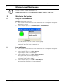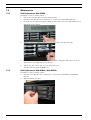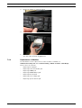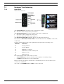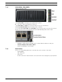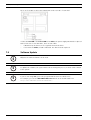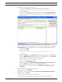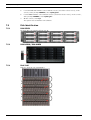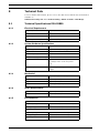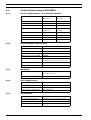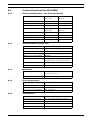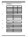
1
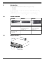
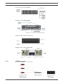
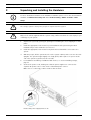
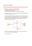
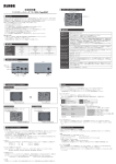
DSDA iSCSI Disk Array Series
DSA-S5B50 | DSA-N2B20 | DSA-N2B50
en
Installation Guide
DSDA iSCSI Disk Array Series
Table of Contents | en
1
Table of Contents
1
Precautions
3
2
Introduction
4
2.1
Systems at a Glance
4
3
Unpacking and Installing the Hardware
6
4
Delivery Status
7
5
Configuration through the Web Interface
8
5.1
Configuration of the Network Settings and Access to the Interface
5.2
Time and Date Settings
11
5.3
Configuring the Volume
12
5.4
Creating an Initiator Group
14
5.5
Creating LUNs
14
6
Adding Storage
17
6.1
Installing a Shelf
17
7
Monitoring and Maintenance
23
7.1
Monitoring the System
23
7.2
Maintenance
24
7.3
Hardware Troubleshooting
26
7.4
Software Update
28
7.5
Disk Identification
30
8
Technical Data
31
8
8.1
Technical Specifications DSA-S5B50
31
8.2
Technical Specifications DSA-N2B20
32
8.3
Technical Specifications DSA-N2B50
33
8.4
Technical Specifications Disk Shelf Expansion Unit –DSX-N2X00-14AT
34
9
Trademarks
35
Bosch Security Systems
Installation Guide
V 1 | 2008.08
2
en | Table of Contents
V 1 | 2008.08
DSDA iSCSI Disk Array Series
Installation Guide
Bosch Security Systems
DSDA iSCSI Disk Array Series
1
Precautions | en
3
Precautions
–
The system is heavy even without disks installed. At least two people are required to
install the system.
–
The rack cabinet into which this system will be installed must support overcurrent
protection and must not be overloaded by the modules installed. Other requirements,
such as ventilation airflow, rack stabilizing features, electrical earth, and electrical
distribution, must comply with the technical specifications listed in Section 8 Technical
Data, page 31 and in the documentation that came with this product.
–
All systems must be mounted with and supported by the rails provided and secured in
position by the four screws in the front side flanges. In no instance is a system to be
mounted by the front side flanges only as this will result in the deforming of the systems
chassis causing unacceptably high pressures and/or torques to be applied to internal
components resulting in various failure modes.
–
System Integrators should ensure that any integrated storage solution that includes this
product has been tested and proved to meet government regulations and codes for
subjects including safety, fire, and electrical.
–
Make sure you have a soft, clean surface to place your system before working on it.
Placing the system on a rough surface during servicing may damage the chassis finish.
–
Do not remove any module or component item from its anti-static bag until you are ready
to install it. Pick up and hold modules by their edges or canister. Avoid touching PCBs
and connector pins.
–
Observe all standard ESD prevention methods, e.g., wear an anti-static wristband to
prevent static electricity from damaging the electric components.
–
When replacing components insert them as gently as possible while assuring full
engagement. Vibration or shock can damage hard drives in the affected unit or other
units in the rack. Hard drives are very sensitive to shock and vibration, especially while in
operation and should always be handled very carefully.
–
After all equipment is installed in a rack dress the power and data cables such that power
cables are not resting against data (SCSI, IP, RS-232) cables.
Bosch Security Systems
Installation Guide
V 1 | 2008.08
4
en | Introduction
2
DSDA iSCSI Disk Array Series
Introduction
This guide explains the installation of the digital storage systems of type
–
DSA-S5B50
–
DSA-N2B20
–
DSA-N2B50
for either direct storage of recorded video data or for use with the VRM Video Recording
Manager application.
Additional documentation is available on the internet and can be downloaded from
www.boschsecurity.com under Product Catalog > CCTV > IP Video > Disk Arrays.
2.1
Systems at a Glance
DSA-S5B50
DSA-N2B20
DSA-N2B50
12 / 6 disks, 1 TB each
12 disks, 750 GB each
20 disks, 750 GB each
shelf expansion units
shelf expansion units
available with 14 disks
available with 14 disks
(750 GB) each
(750 GB) each
RAID-DP
RAID-DP
RAID-4
RAID-DP optionally
configurable
2.1.1
Hardware Overview
Example overview (DSA-N2B20):
V 1 | 2008.08
Installation Guide
Bosch Security Systems
DSDA iSCSI Disk Array Series
Introduction | en
5
Example front side (DSA-N2B20):
Example rear side (DSA-N2B20):
Expansion unit – disk shelf: Front side
Expansion unit – disk shelf: Rear side
2.1.2
CCTV Integration
Example for installation without VRM:
Bosch Security Systems
Installation Guide
V 1 | 2008.08
6
en | Unpacking and Installing the Hardware
3
DSDA iSCSI Disk Array Series
Unpacking and Installing the Hardware
NOTICE!
i
!
!
For more detailed information on the hardware installation please refer to the documentation
available on www.boschsecurity.com under Product Catalog > CCTV > IP Video > Disk
Arrays.
WARNING!
The storage system is heavy. Two people are required to lift a system.
CAUTION!
Only use the rail kit supplied with the system. Using a different rail kit can cause injury to you
or damage to your system.
1.
Unpack your system by opening the packing box and lifting the outer shipping box off the
pallet.
2.
Install the appropriate rack mount for your installation and system using the Rack
Installation flyer in the rail kit box for reference.
3.
Install the appropriate rack mount for any disk shelves that will be connected to the
system
4.
With two people, lift the system into the rack or system cabinet, and secure it to the rack
uprights. The system weighs slightly over 30 kg (67 lb) and requires one person at the
end of the system to guide it into the rail ends.
5.
For installation and wiring of additional disk shelves, see Section 6 Adding Storage,
page 17.
6.
Connect the power cords, making sure that the power supplies are connected to
separate AC power sources. This ensures redundant power sources.
Make sure to set the power cable retention clips properly.
Ensure that power supply LEDs are lit.
V 1 | 2008.08
Installation Guide
Bosch Security Systems
DSDA iSCSI Disk Array Series
4
Delivery Status | en
7
Delivery Status
For use with the VRM Video Recording Manager application or for direct recording from Bosch
cameras and senders, the system should be configured following the steps in the next
chapter.
Preconfigured settings upon delivery:
DSA-S5B50
DSA-N2B20
DSA-N2B50
RAID type
RAID-4
RAID-DP
RAID-DP
Volume
vol0 with 2 disks
vol0 with 3 disks
vol0 with 3 disks
IP address
10.10.10.10
10.10.10.10
10.10.10.10
IP address (2nd port) 10.10.10.11
10.10.10.11
10.10.10.11
User (Web interface)
root
root
root
Password
<blank>
<blank>
<blank>
All further configuration is done through the Web-based user interface or VRM 1.5 or higher.
Each system is delivered with the preconfigured IP address 10.10.10.10 on Ethernet port e0a
and IP address 10.10.10.11 on the second Ethernet port e0b.
Bosch Security Systems
Installation Guide
V 1 | 2008.08
8
en | Configuration through the Web Interface
5
DSDA iSCSI Disk Array Series
Configuration through the Web Interface
NOTICE!
i
Do not use the S5B50 management software StoreVault Manager for the configuration. The
DSA series come with a dedicated Bosch standardized system layout. StoreVault Manager is
not compatible with the Bosch layout.
Follow these steps to configure each system. This procedure is nearly identical for all three
types of storage systems.
1.
Turn on the system.
DSA-S5B50: The power button is located on the front side on the left-hand side.
DSA-N2B20 / DSA- N2B50 / additional disk shelves: There is a power switch on each
power supply unit (right- and left-hand side) on the rear side of the device.
If there are additional disk shelves installed, first power on the base unit, then power on
the expansion units.
i
i
5.1
NOTICE!
It can take a few seconds until the LEDs on your system power supplies light up.
NOTICE!
The Java Runtime Environment must be installed on your computer in order to use the Web
interface. Always use the most recent version.
Configuration of the Network Settings and Access to the
Interface
All systems are delivered with a default IP address configuration of 10.10.10.10, netmask
255.0.0.0. In order to connect to the system, you need to configure a network interface on
your computer to use the same network.
V 1 | 2008.08
Installation Guide
Bosch Security Systems
DSDA iSCSI Disk Array Series
2.
Configuration through the Web Interface | en
9
Select from the Control Panel of your computer Network Connections, Properties.
Here, configure your network interface to use IP address 10.10.10.9 with Subnet mask
255.0.0.0.
Example screen:
i
NOTICE!
The IP address 10.10.10.9 is an example. The IP addresses 10.10.10.10 and 10.10.10.11 are
the default IP addresses for the storage system and cannot be used otherwise.
3.
Connect your computer directly to the network port labeled e0a on the storage system,
using a crossover cable.
Alternatively, connect your computer to the network the storage system is connected to.
4.
Open a Web browser and enter http://10.10.10.10/na_admin.
You will be asked to log in.
Bosch Security Systems
Installation Guide
V 1 | 2008.08
10
en | Configuration through the Web Interface
5.
DSDA iSCSI Disk Array Series
Enter root as the user name, leave the password blank.
The FilerView start page loads and shows an overview on the system status.
6.
Click the FilerView icon. This opens the FilerView administration interface in a new
window. On the left-hand side of the FilerView interface, you will see the navigation
panel.
For direct help on a specific topic, click one of the ?-buttons.
i
NOTICE!
FilerView is only available in English.
7.
V 1 | 2008.08
Select Network > Manage Interfaces.
Installation Guide
Bosch Security Systems
DSDA iSCSI Disk Array Series
8.
Configuration through the Web Interface | en
11
Click Modify next to the network interface labeled e0a and configured with IP address
10.10.10.10.
9.
Enter the IP address information for the network. Change IP Address and Netmask to
the desired value. Leave Broadcast blank.
Example screen:
10. Set Media Type to 10/100/1000 Mbit Auto-negotiate.
Leave the Trusted option enabled.
11. Click Apply to confirm the changes. As this reconfigures the network interface you are
connected to, the page will fail to load after clicking the Apply button.
12. Reset the network settings of your computer to its original settings or settings suitable
for your CCTV network.
13. Reconnect to the FilerView interface using the new IP address of the storage system.
Enter http://<newIPaddress>/na_admin and log in using root as the user name and
leaving the password blank.
14. On the FilerView start page click the FilerView icon to open the administration interface
again.
5.2
Time and Date Settings
15. In the navigation panel, select Filer > Set Date/Time.
The current date and time are displayed. If the time settings are incorrect, click Modify
Date/Time. This starts the Date/Time Wizard. While the wizard guides you through the
set-up, click Next to go to the next step. Click Cancel, if you do not want to continue the
procedure.
16. From the list, select the System Time Zone. Click Next.
17. Set System Time Update Method to Manual. Click Next.
18. Enter the current time and date. Click Next.
Bosch Security Systems
Installation Guide
V 1 | 2008.08
12
en | Configuration through the Web Interface
DSDA iSCSI Disk Array Series
19. The changes are summarized on the Commit screen.
Click Commit to apply the new settings.
NOTICE!
i
5.3
If you are using the VRM Video Recording Manager application (Version 1.5 or higher), all
further settings are made through VRM.
If you use the digital storage systems for direct recording, continue with the following steps.
Configuring the Volume
The system is preconfigured with one volume that contains either two or three hard disks. You
need to add the remaining disks of your system to the volume in order to use their capacity.
20. In the navigation panel, select Volumes > Manage.
The preconfigured volume, named vol0, is listed.
21. Click vol0 to display and change the properties of the volume.
22. Click Add Disks. This starts a wizard for adding disks to the existing volume.
23. Click Next on the welcome screen of the Volume Wizard.
24. Disk Selection: Check Automatic. Click Next.
25. Disk Size: Select Any Size. Click Next.
26. Number of Disks:
–
DSA-S5B50: Select the maximum number of disks available from the list. Click Next.
–
DSA-N2B20 / DSA-N2B50, no extension shelves: Select the maximum number of
disks available from the list. Click Next.
–
DSA-N2B20 with extension shelves: Add 9 disks. Later on, create further volumes as
described in Section 6.1.4 Adding New Volumes, page 19.
Click Next.
–
DSA-N2B50 with extension shelves: Add 17 disks. Later on, create further volumes as
described in Section 6.1.4 Adding New Volumes, page 19.
Click Next.
V 1 | 2008.08
Installation Guide
Bosch Security Systems
DSDA iSCSI Disk Array Series
Configuration through the Web Interface | en
13
27. The changes are summarized on the Commit screen.
Click Commit to apply the new settings.
By default, one disk is left as a spare disk. If no spare disk is needed, this disk can be
added to the volume manually. To do so, please continue with step 28.
If you would like to keep the spare disk, please continue with step 32.
28. In the navigation panel, select Filer > Use Command Line.
29. Enter vol add vol0 1 (or replace vol0 with the volume to which you want to add the disk).
30. A warning displays. Enter y (yes) to confirm the action.
A message confirms that the disk has been added.
31. Click Disconnect to disconnect from the command line console.
!
Bosch Security Systems
CAUTION!
If the settings made here are altered later, all data stored on the disks is lost as the RAID
group needs to be reconstructed.
Installation Guide
V 1 | 2008.08
14
en | Configuration through the Web Interface
5.4
DSDA iSCSI Disk Array Series
Creating an Initiator Group
32. In the navigation panel, select LUNs > Initiator Groups > Add.
The Add Initiator Group screen displays.
33. Group Name: Enter VRM_UNITIGROUP0.
34. Type: Select iSCSI.
35. Operating System: Select Linux.
36. Initiators: Enter the initiator names of all cameras and senders that shall write to this
system.
The initiator name of a device is obtained from the Configuration Manager program.
There, select the device. Then, click the iSCSI tab. You can copy the iSCSI Initiator name
to the clipboard.
Alternatively, the initiator name can be obtained from the VRM Configurator or the Web
interface of a device.
37. Click Add to create the initiator group.
5.5
Creating LUNs
38. Calculate the size for each LUN.
In the navigation panel, select Volumes > Manage. Here, the available size of the volume
is displayed. Divide that value by 16 to get the size of each individual LUN.
NOTICE!
Each storage system needs a minimum of 16 LUNs to provide the best performance.
A total of 16 LUNs is considered best practice.
i
If you already know that you will add additional storage shelves, you may consider to create
less than 16 LUNs here, as additional LUNs will be created for the additional volumes. In that
case, divide the size available for the volume by the number of LUNs you plan to create for the
volume.
Example: For a total of four volumes you might want to create four LUNs for each volume,
giving you a total of 16 LUNs.
V 1 | 2008.08
Installation Guide
Bosch Security Systems
DSDA iSCSI Disk Array Series
Configuration through the Web Interface | en
15
The following procedure must be carried out for each LUN to be created.
39. In the navigation panel, select LUNs > Wizard.
Click Next on the LUN Wizard welcome screen.
40. Path: Enter /vol/vol0/lun1.
The first part of this path is always vol, the second part is the name of your volume
(vol0), the third part is the name of your LUN (change this for all further LUNs you are
creating).
Example: Enter /vol/vol0/lun2, /vol/vol0/lun3, /vol/vol0/lun4 ... for further LUNs.
41. Size: Enter the size calculated for your LUNs (available size of the volume divided by the
number of LUNs to be created for this volume).
42. LUN Protocol Type: Select Linux.
43. Leave Space-reserved enabled and leave Description blank. Click Next.
44. On the Add Initiator Groups screen, click Add Group.
45. Select Use existing initiator group. Click Next.
46. Select the VRM_UNITIGROUP0 that you have created before. Click Next.
Bosch Security Systems
Installation Guide
V 1 | 2008.08
16
en | Configuration through the Web Interface
DSDA iSCSI Disk Array Series
47. On the Add Initiator Groups screen, click Next.
48. LUN ID: Leave this field blank. The lowest available ID will be used automatically.
Click Next.
49. The changes are summarized on the LUN Wizard: Commit Changes screen.
Click Commit to create the LUN.
If the LUN has been created successfully, a Success! screen will display.
50. Use the LUN Wizard to create all 16 (or the desired number of) LUNs.
The system configuration is now done.
51. It is recommended to change the password for the Web interface access.
In the navigation panel, select Security > Change Password.
52. If no further storage is to be added, disconnect your computer from the storage system.
Connect the storage system to the CCTV network by plugging the network cable (not
supplied) into the network port, labeled e0a.
V 1 | 2008.08
Installation Guide
Bosch Security Systems
DSDA iSCSI Disk Array Series
6
Adding Storage | en
17
Adding Storage
Storage shelves can be added to the DSA-N2B20 and the DSA-N2B50 system.
Each expansion unit comes with 14 disks, 750 GB each.
Shelves are daisy-chained in a so-called loop. The first shelf added to a storage system is
directly connected to the storage system. Each following shelf is connected to the last shelf in
the existing loop, with a maximum of six shelves in one loop for the DSA-N2B50 and a
maximum of four shelves for the DSA-N2B20.
6.1
Installing a Shelf
1.
6.1.1
Physically install and secure the shelf onto support brackets and rack.
Setting the Shelf ID
Each shelf will have to have an ID. The shelf ID represents the position in the loop. The first
shelf (which you attach directly to your storage system) has ID #1, the second shelf (attached
to shelf number one) has ID #2 and so on.
Bosch Security Systems
Installation Guide
V 1 | 2008.08
18
en | Adding Storage
DSDA iSCSI Disk Array Series
2.
Set the correct Shelf ID by pressing the + or – button at the back of the shelf, next to the
ID display.
Note: Do not use identical IDs for different shelves.
6.1.2
Connecting the Power Supplies
3.
If not already done, power on the base unit. On the shelf, connect both power supplies
and switch them on. Wait 30 seconds to allow the shelf to initialize.
Make sure that the shelf displays the correct shelf ID on the front display before you
continue.
V 1 | 2008.08
Installation Guide
Bosch Security Systems
DSDA iSCSI Disk Array Series
6.1.3
Adding Storage | en
19
Connecting the Shelf
4.
Connect the shelves using the supplied cables.
–
For the first shelf:
Insert an SFP into the In port of each of the two I/O modules at the back of the shelf
to convert them to optical ports, making sure that the SFP has the correct position
before inserting it.
Plug in one end of the optical cable to the In port of the lower I/O module on your
shelf.
Plug the other end into the Fibre Channel (FC) port labeled 0a on the storage controller.
Connect one end of the second optical cable into the In port of the upper I/O module of your shelf.
Connect the other end to the second FC port on your storage system, labeled 0b.
–
For additional shelves:
Insert an SFP into the In port of each of the two I/O modules at the back of the shelf
to convert them to optical ports, making sure that the SFP has the correct position
before inserting it. Repeat this for the Out port of the last shelf in your existing loop.
Connect one end of the SFP-SFP cable to the In port of the upper I/O module in your
new disk shelf.
Connect the other end to the Out port of the upper I/O module of the last shelf in
your existing loop.
Connect one end of the SFP-SFP cable to the In port of the lower I/O module in your
new disk shelf.
Connect the other end to the Out port of the lower I/O module of the last shelf in
your existing loop.
NOTICE!
i
It might take up to 60 seconds for the storage system to recognize the new disks.
The procedure as described above is only valid for new disk shelves. If you want to assign disk
shelves that have already been used by a different storage controller, please refer to the
original NetApp documentation.
5.
Log in to the FilerView administration interface as described in Section 5 Configuration
through the Web Interface, page 8.
6.
In the navigation panel, select Storage > Disks > Manage and verify that the system
shows the new disks, i.e. View Type is set to Spare Disks.
NOTICE!
i
6.1.4
If you are using the VRM Video Recording Manager application (Version 1.5 or higher), all
further settings are made through VRM.
If you use the digital storage systems for direct recording, continue with the following steps.
Adding New Volumes
7.
In the navigation panel, select Volumes > Add.
Click Next in the welcome screen of the Volume Wizard.
8.
Bosch Security Systems
Volume Type Selection: Set to Traditional. Click Next.
Installation Guide
V 1 | 2008.08
20
en | Adding Storage
DSDA iSCSI Disk Array Series
9.
Volume Parameters:
Volume Name: Enter a name for the new volume. The name should consist of the word
vol and the ID of the disk shelf you just added (e.g. the volume for the first shelf you are
adding to your storage system will be vol1, the volume for the second shelf will be called
vol2 and so on).
Leave the second and third parameter to their default value and enable Double Parity.
Click Next.
10. RAID Group Size: Set to 14. Click Next.
11. Disk Selection: Set to Automatic. Click Next.
12. Disk Type: Select Any Type. Click Next.
13. Disk Size: Select Any Size. Click Next.
14. Number of Disks: Select the maximum value available. Click Next.
15. The changes are summarized on the Commit screen.
Click Commit to apply the new settings.
By default, one disk is left as a spare disk. If no spare disk is needed, this disk can be
added to the volume manually. To do so, please continue with step 16. If you would like
to keep the spare disk, please continue with step 20.
16. In the navigation panel, select Filer > Use Command Line.
17. Enter vol add vol1 1 (... vol add vol2 1 ... vol add vol3 1 ... and so on, depending on the
volume you are setting up).
18. A warning displays. Enter y (yes) to confirm the action.
A message confirms that the disk has been added.
19. Click Disconnect to disconnect from the command line console.
20. In the navigation panel, select Volumes > Manage.
21. Click the name of the new volume to open the Volume Properties.
22. Click Modify to change the properties.
The Modify Volume Wizard displays.
23. Volume: Verify that the newly created volume is selected. Click Next.
V 1 | 2008.08
Installation Guide
Bosch Security Systems
DSDA iSCSI Disk Array Series
Adding Storage | en
21
24. On the following two screens, click Next and leave all options to their default value.
On the third screen (Other), uncheck Access Time.
25. The changes are summarized on the Commit screen.
Click Commit to apply the new settings.
26. In the navigation panel, select Volumes > Snapshots > Configure.
Choose the newly created volume from the drop-down list.
Uncheck Scheduled.
Click Apply to commit the change.
27. Repeat steps 7 to 26 for each volume you wish to add.
Bosch Security Systems
Installation Guide
V 1 | 2008.08
22
en | Adding Storage
6.1.5
DSDA iSCSI Disk Array Series
Creating LUNs
For each newly created volume, you must create at least one LUN, as previously created LUNs
cannot not be reconfigured to use them for the new volume.
i
NOTICE!
The size of the LUNs for Bosch applications is limited to 2TB.
28. Create LUNs for the volume, as described in Section 5.5 Creating LUNs, page 14.
Be sure to use the correct volume when setting the path for each LUN.
Example: /vol/vol1/lun0
V 1 | 2008.08
Installation Guide
Bosch Security Systems
DSDA iSCSI Disk Array Series
7
Monitoring and Maintenance | en
23
Monitoring and Maintenance
i
NOTICE!
You can find more detailed documentation on
www.boschsecurity.com under Product Catalog > CCTV > IP Video > Disk Arrays.
7.1
Monitoring the System
7.1.1
Using the FilerView Monitor
The system should be monitored. An overall system status monitor is provided by the
FilerView administration interface.
1.
Connect to the FilerView interface as described in Section 5 Configuration through the
Web Interface, page 8.
2.
In the navigation panel, select Real Time Status > Health Monitor.
The overall Health Monitor opens in a new browser window.
Keep this window open and check the status regularly.
3.
In the navigation panel, select Real Time Status > Filer At-A-Glance.
Data traffic, CPU load etc. are visualized here.
7.1.2
Logs and Reports
1.
Connect to the FilerView interface as described in Section 5 Configuration through the
Web Interface, page 8.
2.
In the navigation panel, select Filer > Report.
A general report on the system displays.
3.
In the navigation panel, select Filer > Syslog Messages.
The log file for all system messages displays.
4.
In the navigation panel, select Network > Report.
Information on the network displays.
5.
In the navigation panel, select LUNs > iSCSI > Report.
The iSCSI status and further information displays.
Bosch Security Systems
Installation Guide
V 1 | 2008.08
24
en | Monitoring and Maintenance
DSDA iSCSI Disk Array Series
7.2
Maintenance
7.2.1
Disk Replacement DSA-S5B50
Follow these steps to replace a disk:
1.
Remove the new disk drive from the antistatic bag.
2.
Determine the disk drive to be replaced, see Section 7.5.1 DSA-S5B50, page 30.
3.
Press the release latch of the drive. Swing the drive bay cover to the right until it is at a
right angle to the chassis.
4.
5.
Slide the entire assembly toward you in order to pull it out of the drive bay.
Press the release latch of the new replacement drive. Swing the drive bay cover to the
right until it is at a right angle to the chassis.
6.
Slide in the drive carrier and close the drive bay cover.
The drive LED should be lit green now.
7.2.2
Disk Replacement DSA-N2B20 / DSA-N2B50
Follow these steps to replace a disk:
1.
Determine the disk drive to be replaced, see Section 7.5.2 DSA-N2B20 / DSA-N2B50,
page 30.
2.
V 1 | 2008.08
Grasp and pinch the latch.
Installation Guide
Bosch Security Systems
DSDA iSCSI Disk Array Series
Monitoring and Maintenance | en
3.
Rotate the handle to extract the disk.
4.
Support the bottom of the drive to remove it.
5.
25
Reverse these steps to replace the hard disk.
The drive LED should be lit green now.
7.2.3
Replacement of Modules
Documentation on the replacement of other modules is available on
www.boschsecurity.com under Product Catalog > CCTV > IP Video > Disk Arrays.
Refer to these documents:
Bosch Security Systems
–
Replacing CF Card.pdf
–
Replacing Controller Module.pdf
–
Replacing DIMMS.pdf
–
Replacing NVMEM Battery.pdf
–
Replacing PCI Card.pdf
–
Replacing Power Supply.pdf
–
Replacing System Chassis.pdf
Installation Guide
V 1 | 2008.08
26
en | Monitoring and Maintenance
DSDA iSCSI Disk Array Series
7.3
Hardware Troubleshooting
7.3.1
DSA-S5B50
LEDs on front side, left:
If the Power Indicator is not lit green, the system has no power.
X
Check the cables and press the power button.
If the Ethernet Link LED is not lit, no network connection is established.
1.
Check if the cable is plugged in at both ends.
2.
Check the cable and, if neccessary, replace it.
If the Ethernet Activity LED is blinking, data is currently being transferred.
Each disk has a Drive Status Indicator LED to the left-hand side. If it is lit amber, a drive fault
is indicated.
The drive status indicator LED on the right-hand side may show the following codes:
LED Code
Indications
00
Booting firmware
12
Booting ONTAP
11
ONTAP boot complete
E1
DHCP failed on both network ports
E2
Battery too low
E3
Battery broken
Each power supply has two LEDs on the rear side.
–
A green blinking LED indicates that the power supply is on stand-by voltage.
–
An amber lit LED indicates a power supply fault.
On the rear side, two LEDs are found next to each Ethernet port. If only one LED is lit, no
connection is established.
If the LED on the NVRAM card is lit amber, a fault is indicated.
V 1 | 2008.08
Installation Guide
Bosch Security Systems
DSDA iSCSI Disk Array Series
7.3.2
Monitoring and Maintenance | en
27
DSA-N2B20 / DSA-N2B50
LEDs on front side, right:
If the Power LED is not lit green, the system has no power.
X
Check the cables and switch the system on.
If the Fault LED is lit amber, the system is halted, or an error is indicated.
A blinking Controller LED indicates activity of the controller.
A corresponding Power LED and a Fault LED are also located on the rear side of the system.
On the rear side, next to the Ethernet ports, two fault-indicating LEDs can be found.
–
NVRAM Battery LED blinking green:
–
Controller Module Status LED lit amber:
NVRAM is in battery-backed standby-state (contains data not written to disk yet).
System is initializing or system fault.
7.3.3
Disk Shelves
There is a corresponding LED next to each SFP slot on the rear side of the shelf:
–
LED lit green:
SFP connection.
–
LED not lit:
No SFP connection. Check all cable connections and ensure all plugs are properly fitted.
Bosch Security Systems
Installation Guide
V 1 | 2008.08
28
en | Monitoring and Maintenance
DSDA iSCSI Disk Array Series
There are four LEDs on the power supply unit on the rear side of each shelf.
If either the Fan LED or the Power LED are lit amber, the power supply unit must be replaced.
At the front side of each disk drive, there are two LEDs.
7.4
–
If no LED is lit, the drive is not recognized. Reinsert the drive.
–
If one LED is lit amber, a fault is indicated. The drive must be replaced.
Software Update
i
i
NOTICE!
Only Bosch certified software can be used.
NOTICE!
To update the software, the system must reboot. During this process, no data can be written
to the system.
NOTICE!
i
V 1 | 2008.08
If you are not using VRM, you need a program that functions as a Web server.
For example, you can use AIDeX Mini-Webserver which can be downloaded from
http://www.aidex.de/software/webserver/.
Installation Guide
Bosch Security Systems
DSDA iSCSI Disk Array Series
1.
Monitoring and Maintenance | en
29
Upload the new software to a Web server
–
If you are using VRM, place the file that contains the new version in
C:\Program Files\Bosch\Video Recording Manager\VRM Server\web
on your VRM Server.
–
If you are not using VRM, start a Web server tool, for example MiniWebServer.exe,
select a root directory and copy the new software version into this root directory.
Example screen:
2.
Download and install the new version on the storage controller hard disks:
Connect to the console of the storage device. To connect to the console, select Filer >
Use Command Line in the navigation panel of the FilerView administration interface.
–
If you are using VRM:
On the console, enter
software install http://username:password@<VRM Server IP>/
<Filename>
Replace <username> and <password> with the login information of your VRM server.
Replace <VRM Server IP> with the IP address of your VRM server and <Filename>
with the name of the file that contains the new version.
Wait a few minutes for the installation to complete.
–
If you are using MiniWebServer.exe:
On the console, enter software install http://<MiniWebServer>/<filename> and
replace <filename> with the name of the software update file.
Wait until the success message displays: Installation of setup.exe-7.xxx_e.exe
completed.
3.
Download the new software to the CF card:
On the console, enter: download.
Wait until the success message displays: Operator requested download completed.
4.
On the console, enter: halt.
The system reboots and stops at the bootloader.
Note that no data can be written on the disks while the system is rebooting.
Bosch Security Systems
Installation Guide
V 1 | 2008.08
30
en | Monitoring and Maintenance
5.
DSDA iSCSI Disk Array Series
If a new mainboard firmware comes with the release (check the release notes), on the
console, at the prompt LOADER>, enter update_flash.
6.
If a new BMC firmware comes with the release (check the release notes), on the console,
at the prompt LOADER>, enter update_bmc.
7.
On the console, enter: bye.
The system reboots with the new software.
7.5
Disk Identification
7.5.1
DSA-S5B50
The disk drives are numbered from 0 to 11:
7.5.2
DSA-N2B20 / DSA-N2B50
7.5.3
Disk Shelf
Disk ID = Shelf ID * 16 + Bay Number
V 1 | 2008.08
Installation Guide
Bosch Security Systems
DSDA iSCSI Disk Array Series
8
Technical Data | en
31
Technical Data
For more detailed information, please refer to the data sheets with the latest information
available on
www.boschsecurity.com under Product Catalog > CCTV > IP Video > Disk Arrays.
8.1
Technical Specifications DSA-S5B50
8.1.1
Electrical Requirements
AC power/Max current
100 V to 120 VAC, 9 A
200 to 240 VAC, 4.5 A
8.1.2
Frequency
50/60 Hz
Heat dissipation BTU/h
1706 BTU, fully loaded
System Hardware Specifications
Chassis
2U, 19”-rack-mountable
Power supplies
Dual redundant, hot pluggable
Disk drives
Up to 12: 1 TB SATA-II drives
Max raw capacity
12 TB
DDR2 memory (system RAM)
2048 MB
Nonvolatile SDRAM (NVRAM)
256 MB—protects “in flight” transactions
for 3 days in the event of a power
loss
Integrated I/O
2 x 10/100/1000 Gigabit Ethernet,
copper
8.1.3
8.1.4
8.1.5
Mechanical
Height
89 mm (2 U) (3.5 in (2 U))
Width
447 mm (17.6 in)
Depth
508 mm (20 in)
Weight
35.8 kg (52 lb), fully loaded
Space Requirements
Front clearance
268 mm (10.55 in)
Rear clearance
414 mm (16.3 in)
Environmental
Temperature
• operating range
0 °C to +40 °C (+32 °F to +104 °F)
• storage range
-10 °C to +65 °C (-40 °F to +149 °F)
Relative humidity
Bosch Security Systems
• operating range
20 to 85%, non-condensing
• storage range
20 to 95%, non-condensing
Operating acoustic noise
66 dBA at 1 m at +23 °C
Installation Guide
V 1 | 2008.08
32
en | Technical Data
DSDA iSCSI Disk Array Series
8.2
Technical Specifications DSA-N2B20
8.2.1
Electrical Requirements – One Controller Module
Input voltage: 100 to 120V
8.2.2
Worst case,
System,
single PSU
two PSUs
• input current measured
3.37 A
3.22 A
• input power measured
332 W
316 W
• thermal dissipation
1133 BTU/hr
1077 BTU/hr
Input voltage: 200 to 240V
Worst case,
System,
single PSU
two PSUs
• input current measured
1.69 A
1.66 A
• input power measured
327 W
305 W
• thermal dissipation
1114 BTU/hr
1039 BTU/hr
Input power frequency
50 to 60 Hz
50 to 60 Hz
System Hardware Specifications
Chassis
2U, 19” rack-mountable
Power supplies
Dual redundant, hot pluggable
Max disk drives
12 x 750 GB SATA II drives
Max raw Capacity
9 TB
DDR2 memory (System RAM)
1024 MB
Nonvolatile SDRAM (NVRAM)
256 MB - protects “in flight” transactions
for 3 days in the event of a power loss.
Integrated I/O
2 Ethernet 10/100/1000 Copper
Remote management (via LAN) Yes
8.2.3
Mechanical
Dimensions (H x W x D)
89 x 447 x 572 mm
(3.5 x 17.6 x 22.5 in)
Weight
8.2.4
8.2.5
V 1 | 2008.08
27.215 kg (60 lb) full
Space Requirements
Front–cooling
152 mm (6 in)
Rear–cooling
305 mm (12 in)
Front of chassis–maintenance
762 mm (30 in)
Rear of chassis–maintenance
915 mm (36 in)
Environmental
Operating temperature
+10 °C to +40 °C (+50 °F to +104 °F)
Nonoperating temperature
-40 °C to +60 °C (-40 °F to +140 °F)
Relative humidity
20 to 80% noncondensing
Acoustic level
N/A
Installation Guide
Bosch Security Systems
DSDA iSCSI Disk Array Series
Technical Data | en
8.3
Technical Specifications DSA-N2B50
8.3.1
Electrical Requirements – One Controller Module
Input voltage: 100 to 120V
8.3.2
Worst case,
System,
single PSU
two PSUs
• input current measured
5.07 A
4.51 A
• input power measured
504 W
439 W
• thermal dissipation
1718 BTU/hr
1497 BTU/hr
Input voltage: 200 to 240V
Worst case,
System,
single PSU
two PSUs
• input current measured
2.46 A
2.40 A
• input power measured
474 W
447 W
• thermal dissipation
1617 BTU/hr
1523 BTU/hr
Input power frequency
50 to 60 Hz
50 to 60 Hz
33
System Hardware Specifications
Chassis
4U, 19” rack-mountable
Power supplies
Dual redundant, hot pluggable
Max disk drives
20 x 750 GB SATA II drives
Max raw Capacity
15 TB
DDR2 memory (System RAM)
2048 MB
Nonvolatile SDRAM (NVRAM)
256 MB - protects “in flight” transactions
for 3 days in the event of a power loss.
Integrated I/O
2 Ethernet 10/100/1000 Copper
Remote management (via LAN) Yes
8.3.3
Mechanical
Dimensions (H x W x D)
175 x 447 x 572 mm
(6.9 x 17.6 x 22.5 in)
Weight
8.3.4
8.3.5
49.895 kg (110 lb)
Space Requirements
Front–cooling
152 mm (6 in)
Rear–cooling
305 mm (12 in)
Front of chassis–maintenance
762 mm (30 in)
Rear of chassis–maintenance
914 mm (36 in)
Environmental
Operating temperature
+10 °C to +40 °C (+50 °F to +104 °F)
Nonoperating temperature
-40 °C to +60 °C (-40 °F to +140 °F)
Relative humidity
20 to 80% noncondensing
Acoustic level
66 dBA at +23 °C
6.6 bels at +23 °C
Bosch Security Systems
Installation Guide
V 1 | 2008.08
34
en | Technical Data
DSDA iSCSI Disk Array Series
8.4
Technical Specifications Disk Shelf Expansion Unit –
DSX-N2X00-14AT
8.4.1
Electrical Requirements
Input voltage: 100 to 120V
Worst case,
System,
single PSU
two PSUs
• input current measured
3.42 A
3.22 A
• input power measured
341 W
321 W
• thermal dissipation
1163 BTU/hr
1095 BTU/hr
Input voltage: 200 to 240V
Worst case,
System,
single PSU
two PSUs
1.63 A
1.60 A
• input current measured
8.4.2
• input power measured
323 W
309 W
• thermal dissipation
1103 BTU/hr
1054 BTU/hr
Input power frequency
50 to 60 Hz
50 to 60 Hz
System Hardware Specifications
Chassis
3U, 19” rack-mountable
Power supplies
Dual redundant, hot pluggable
Max disk drives
14 x 750 GB SATA II drives
Max raw Capacity
10.5 TB
Shelf connectivity
Fibre Channel:
• copper
• fiber
8.4.3
Mechanical
Dimensions (H x W x D)
113 x 447 x 552 mm
(5.25 x 17.6 x 22 in)
Weight
8.4.4
8.4.5
V 1 | 2008.08
30.8 kg (68 lb), fully loaded
Space Requirements
Front–cooling
153 mm (6 in)
Rear–cooling
305 mm (12 in)
Front of chassis–maintenance
559 mm (25 in)
Rear of chassis–maintenance
305 mm (12 in)
Environmental
Operating temperature
+5 °C to +40 °C (+41 °F to +104 °F)
Nonoperating temperature
-40 °C to +60 °C (-40 °F to +140 °F)
Relative humidity
20 to 80% noncondensing
Acoustic level
58 dBA at +23 °C
Installation Guide
Bosch Security Systems
DSDA iSCSI Disk Array Series
9
Trademarks | en
35
Trademarks
Java is a trademark of Sun Microsystems.
Data ONTAP and RAID-DP are trademarks of NetApp.
Bosch Security Systems
Installation Guide
V 1 | 2008.08
36
en | Trademarks
V 1 | 2008.08
DSDA iSCSI Disk Array Series
Installation Guide
Bosch Security Systems
Bosch Security Systems
Robert-Koch-Straße 100
D-85521 Ottobrunn
Germany
Telefon
089 6290-0
Fax
089 6290-1020
www.boschsecurity.com
© Bosch Security Systems, 2008