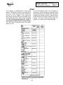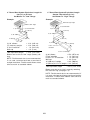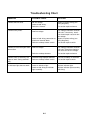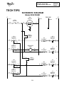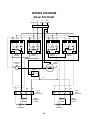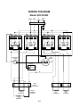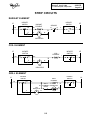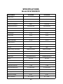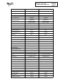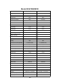
1
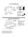
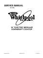
SERVICE MANUAL
for the
30" ELECTRIC MODULAR
DOWNDRAFT COOKTOP
February, 1996
Printed in U.S.A.
LIT 4321972
THIS MANUAL CONTAINS INFORMATION
NECESSARY FOR INSTALLING AND SERVICING THE FOLLOWING WHIRLPOOL 30"
ELECTRIC MODULAR DOWNDRAFT
COOKTOP, MODEL:
RC8700ED
RC8720ED
THE MANUAL IS DESIGNED TO BE USED
ONLY BY QUALIFIED SERVICE PERSONNEL. THE SERVICE INFORMATION IS ORGANIZED TO HELP YOU EASILY FIND WHAT
YOU NEED.
CHECK YOUR LOCAL BUILDING CODE FOR
THE PROPER MODE OF INSTALLATION. IN
THE ABSENCE OF LOCAL CODES, THIS UNIT
SHOULD BE INSTALLED IN ACCORDANCE
WITH THE NATIONAL ELECTRICAL CODE,
ANSI/NFPA NO. 70 - 1990, OR C22.1 CANADIAN ELECTRICAL CODE, PART 1.
- ii -
Cooking Products Service Manual
4321973
Original April, 1996
© 1996 Whirlpool Corporation
Page iii
Table of Contents
Page
Important Safety Information ....................................................................................................... iv
Installation Highlights .......................................................................................................................1-1
Before You Start ..........................................................................................................................1-1
Cooktop Dimensions ...................................................................................................................1-1
Cutout Dimensions ......................................................................................................................1-2
Clearance Dimensions ................................................................................................................1-2
Tools & Material You Will Need ................................................................................................1-3
Venting Requirements ................................................................................................................1-4
Installing The Cooktop ............................................................................................................. 1-10
Electrical Supply Requirements ............................................................................................. 1-11
Electrical Connections ............................................................................................................. 1-12
Venting Operation Check ........................................................................................................ 1-15
Theory Of Operation .........................................................................................................................2-1
The Coil Elements .......................................................................................................................2-1
The Radiant Elements ................................................................................................................2-2
The Grill Elements .......................................................................................................................2-3
The Fan Motor ..............................................................................................................................2-4
Component Access ...........................................................................................................................3-1
Cooktop Components..................................................................................................................3-1
Component Locations .............................................................................................................3-1
Removing The Control Panel & The Surface Unit Indicator Light .................................... 3-2
Removing The Control Switch ...............................................................................................3-3
Removing The Maintop ...........................................................................................................3-4
Removing The Cooktop ..........................................................................................................3-4
Removing A Terminal Block ................................................................................................... 3-6
Removing The Fan Motor .......................................................................................................3-7
Module Components ...................................................................................................................3-8
The Ceramic Surface Unit RCM30DB/Q — Removing
The Glass, Element, Or Limiter .........................................................................................3-8
The Coil Surface Unit RCM10DB/Q — Removing
A Coil Element & Connector ............................................................................................ 3-10
The Grill RCM20DB — Removing The Grill Element ...................................................... 3-12
Removing A Terminal Plug Connector .............................................................................. 3-13
Component Testing ...........................................................................................................................4-1
Troubleshooting ...........................................................................................................................4-1
Tech Tips ............................................................................................................................................5-1
Schematic Diagram — Model RC8700ED ................................................................................5-1
Wiring Diagram— Model RC8700ED ........................................................................................5-2
Schematic Diagram — Model RC8720ED ................................................................................5-3
Wiring Diagram— Model RC8720ED ........................................................................................5-4
Strip Circuits .................................................................................................................................5-5
Specifications ...............................................................................................................................5-6
Model Number Designation ..................................................................................................... 5-10
30 " Electric Modular Downdraft Cooktop Warranty ............................................................. 5-11
- iii -
IMPORTANT SAFETY INFORMATION
This service manual is intended for factory-service
technicians only. We recommend that customers
DO NOT service their own units, because of the
complexity and risk of high-voltage electrical shock.
WARNING
Fire Hazard
The following information is used throughout this
manual, and should be read carefully.
Do not obstruct the flow of combustion and
ventilation air.
Electrical Shock Hazard
CAUTION
It is the customer’s responsibility to:
•
•
Contact a qualified electrical installer.
Assure that electrical installation is adequate and in conformance with the National Electrical Code, ANSI/NFPA 70—
latest edition*, and all local codes and ordinances.
• Take special care when drilling holes into
the wall for venting or electrical wiring.
Electrical wires may be concealed behind
the wall covering.
• Disconnect the power to any electrical
circuits that could be affected by the installation of this cooktop.
Failure to do so could result in fire, electrical
shock, or other personal injury.
Information that will help you avoid actions
that could cause product damage (scratches,
dents, etc.) and damage to personal property.
WARNING
Information that alerts you to potentially dangerous conditions. These conditions can
cause serious personal injury (burns, fire and
electrical shock, etc.) if the suggested procedures are not observed.
Personal Injury Hazard
To eliminate the risk of burns or fires, do not
install cabinets or store things above the
cooktop. If cabinets are already installed
above the cooktop, install a range hood to the
bottom of the cabinet to prevent reaching over
the heated cooking surface. The range hood
should stick out a minimum of 5-inches (12.7
cm) from the front of the cabinets.
Reaching over a heated cooking surface
could result in a serious burn or other injury.
* Copies of the standards listed above may
be obtained from:
National Fire Protection Association
Batterymarch Park
Quincy, Massachusetts 02269
- iv -
Cooking Products Service Manual
Original April, 1996
4321972
© 1996 Whirlpool Corporation
Page 1-1
INSTALLATION HIGHLIGHTS
BEFORE YOU START
Proper installation is your responsibility. Make
sure that you have everything necessary to
properly install the cooktop. It is the responsibility of the installer to comply with the installation clearances specified on the model/serial rating plate. This plate is located on the left
side of the cooktop’s plenum.
The location where the cooktop is installed
should be away from strong draft areas, such
as windows, doors, and strong heating vents
or fans.
The venting duct must terminate outdoors. All
openings in the wall or floor where the cooktop
is to be installed must be sealed.
This appliance is not approved for use in mobile homes.
COOKTOP DIMENSIONS
21-1/2" (54.6 cm)
depth
29-7/8" (75.9 cm)
width
Appliance junction
box is located
under right side
of cooktop.
Blower can be
swiveled 90˚.
16-7/16"
(41.8 cm)
blower housing
depth
grease
containers
3-3/4"
(9.5 cm)
burner box
depth
12-7/16"
(31.6 cm)
11-7/8"
(30.2 cm)
1-1
CUTOUT DIMENSIONS
countertop
27-7/8"
(73.3 cm)
cutout width
15/16" (2.4 cm)
minimum
distance to
backsplash
or vertical
wall
5" (12.7 cm)
20-7/8"
(53.2 cm)
cutout depth
Install rear
wall junction
box in shaded
area. Darker
shaded area is
preferred.
1-7/8" (4.8 cm)
minimum space
to front edge of
countertop
Select required
duct cutout
(see page 1-5
for exhaust duct
cutout location)
Countertop must be
supported within
3" (7.6 cm) of cutout
floor
17"
(43.2 cm)
11"
(27.9 cm)
8"
(20.3 cm)
Minimum Base Cabinet Dimensions:
30" (76.2 cm) base cabinet
24" (61.0 cm) base cabinet depth
25" (63.5 cm) countertop depth
Cutout Preparation:
Decorative laminate —
Chamfer all exposed edges to
prevent chipping laminate.
Cut radius corners and file to
smooth edges to prevent
cracking.
CLEARANCE DIMENSIONS
30" (76.2 cm) minimum
when higher than 18"
(45.7 cm)
See NOTE
for minimum
clearances.
13" (33 cm)
maximum
upper
cabinet
depth
Installation location
should provide sufficient
room for removing
grease containers.
18" (45.7 cm)
minimum
clearance upper
cabinet to
countertop
6" both sides
(15.2 cm)
3/4"
(1.9 cm)
Do not seal cooktop to countertop.
Minimum distance to nearest
combustible vertical surface
extending 18" (45.7 cm) above
cooktop
NOTE: 24" (61.0 cm) minimum when bottom of wood or metal
cabinet is protected by not less than 1/4" flame-retardant
millboard covered with not less than #28 MSG sheet steel, 0.015"
stainless steel, 0.024" aluminum, or 0.020" copper.
30" (76.2 cm) minimum clearance between the top of the cooking
platform and bottom of unprotected wood or sheet metal.
1-2
Side Clearance: 6" (15.2 cm) minimum
clearance between side of cooktop and
side wall is recommended for maximum
ventilation performance.
Rear Clearance: 3/4" (1.9 cm) clearance between rear edge of appliance
and rear wall is required.
Motor/Blower Clearance: 2" (5.1 cm)
minimum clearance between motor and
cabinet is required for proper cooling. 6"
(15.2 cm) clearance is recommended
for servicing access.
Cooking Products Service Manual
Original April, 1996
4321972
© 1996 Whirlpool Corporation
Page 1-3
TOOLS & MATERIAL YOU WILL NEED
ILLUSTRATION
DESCRIPTION
Phillips screwdriver
Metal cutters
Gloves
Caulk gun with weatherproof caulk
Electric or hand drill
Pliers
Safety glasses
Measuring tape
Duct tape
NOT SHOWN:
Wall or roof cap
Metal ductwork
2 sheet metal screws to attach transition duct
to venting adapter.
Two U.L.-listed 1/ 2" conduit connectors.
Flexible, armored, or nonmetallic sheathed
copper cable (with grounding wire) that conforms to existing codes (see “Electrical Supply Requirements” on page 1-11).
Twist-on connectors (number and size depends on installation).
1-3
VENTING REQUIREMENTS
For the quietest and most efficient operation:
WARNING
•
Use 26-gauge minimum galvanized, or 25gauge minimum, aluminum metal duct.
Poor-quality pipe fittings can reduce air
flow. (Note: Local codes may require a
heavier-gauge material.) Flexible metal
duct is not recommended.
•
Do not exhaust more than one downdraft
cooktop into a single duct system.
•
Keep the length of duct and number of
elbows to a minimum.
•
Keep the size of the duct uniform.
•
Use no more than three 90˚ elbows.
•
Do not install two elbows together.
•
If more than one elbow is used, make sure
that there is a minimum of 18 " (45.7 cm) of
straight duct between them. If elbows are
too close together, they can reduce airflow.
•
Do not use a 5 " elbow in a 6 " , or a 3- 1 / 4 "
x10 " system. Use a 5 " to 6 " transition followed by a 6 " elbow, or a 5 " to 3- 1 / 4 " x10 "
elbow transition.
•
Do not reduce the duct work back to a 5 "
system after using 6 ", or 3- 1 / 4 " x10 " fittings.
•
Do not form handmade crimps. They can
restrict airflow.
•
Use recommended duct caps. If an alternate wall, or roof cap is used, be certain
that the cap size is not reduced, and that it
has a backdraft damper.
•
Use duct tape to seal all joints in the duct
system.
•
Use weatherproof caulking to seal the exterior wall or roof opening around the cap.
Fire Hazard
The venting system must terminate outdoors.
Do not end the ductwork in an attic, wall,
ceiling, or other enclosed space.
Do not use 4 " laundry-type wall caps.
Do not use plastic duct.
Do not block the flow of ventilation air.
Failure to follow these instructions could
result in a fire.
Before making any cutouts, make sure that
there is proper clearance within the wall or
floor for the exhaust duct. Do not cut a joist
or stud unless it is absolutely necessary. If
a joist or stud must be cut, a supporting
frame must be constructed.
This downdraft cooktop is rated for 60-feet of
straight duct. If duct length is 10 feet (3 m) or
less, 5 " diameter round ductwork may be used.
If duct length is more than 10 feet (3 m), use 6 "
diameter round or 3- 1/ 4" x 10 " rectangular duct.
Thermal Breaks: In areas of extreme cold
weather, it may be necessary to provide a
short length of nonmetallic duct as close to the
wall as possible to prevent thermal conduction
along the metal duct.
High Altitudes: For altitudes above 4,500 ft
(1,350 m), reduce the recommended duct run
by 20%.
1-4
Cooking Products Service Manual
Original April, 1996
4321972
© 1996 Whirlpool Corporation
Page 1-5
are shown below, and on the following page.
Make sure that there is proper clearance within
the wall or floor for the exhaust duct before
making cutouts.
Determine the best type of venting method to
use. The cooktop can be vented through the
rear wall, or through the floor. Common venting methods and the types of material needed
20-7/8"
(53 cm)
28-7/8"
(73.3 cm)
14-3/4"
(37.5 cm)
6-15/16"
(17.6 cm)
17-1/2"
(44.5 cm)
opening
for venting
through floor
opening for venting
through rear wall
inside wall
cabinet
outside wall
cabinet
peninsula
or island
3-1/4" x 10"
transition
elbow
inside wall to roof
or overhang
peninsula
transition
elbow
directly
outside
between floor joists
1-5
3-1/4" x 10"
cabinet toe space
to outside
12" (30.5 cm)
minimum
6" round
PVC sewer
concrete
pipe
slab
5" to 6" round metal transistion
6" round metal duct
6" round PVC coupling
wall cap
6" round sewer pipe
window well
Seal the space between the outside of
the wall cap inlet and
the inside of the PVC
coupling with weatherproof caulk.
6" round 90˚ PVC
sewer pipe elbow
6" (15.2 cm)
minimum
6" round
PVC coupling
Tightly pack gravel or sand
completely around pipe.
Optional Duct Arrangement Through Window Well Under Concrete Slab
6" round metal duct
wall cap
12" (30.5 cm)
minimum
6" round
PVC sewer pipe
16" (40.6 cm)
maximum
5" to 6" round metal transistion
6" round metal duct
6" round PVC coupling
concrete slab
6" round PVC coupling
6" round PVC sewer pipe
6" round 90˚ PVC
sewer pipe elbow
6" round 90˚ PVC
sewer pipe elbow
30' (9.1 m)
maximum
Tightly pack gravel or sand
completely around pipe.
Optional Duct Arrangement Under Concrete Slab
1-6
Cooking Products Service Manual
Original April, 1996
4321972
© 1996 Whirlpool Corporation
Page 1-7
Chart
To use the following chart, list the number of
each piece, and the length of straight ductwork
that you intend to use. Multiply the equivalent
length by the number of pieces. Add the totals
to get the total equivalent length of your duct
system. Two duct system configuration examples are shown on the following page.
The cooktop is equipped with a dual-range
blower. The blower is factory-set to operate at
the “Low” range (equivalent duct lengths of
30-feet (9.1 m) or shorter. If the equivalent
duct length exceeds 30-feet, the blower must
be set to operate at the “High” range (see page
1-9). Do not change the blower to “High” if
the equivalent duct length is under 30-feet.
This will cause excessive noise and conditioned air loss.
1-7
6 " Round Duct System Equivalent Length 30feet (9.1 m) Or Less
Set Blower To “Low” Range
6 " Round Duct System Equivalent Length
Greater Than 30-feet (9.1 m)
Set Blower To “High” Range
Example:
Example:
blower at “high” range
blower at “low” range
5" to 6" transition
2' (61 cm)
5" to 6" transition
2' (61 cm)
4' (122 cm)
4' (122 cm)
6", 90˚ elbows
6", 90˚ elbows
6" wall cap
6' (183 cm)
6' (183 cm)
(2) 90˚ elbows
12' (366 cm) straight
5 " to 6 " transition
Wall cap
= 10 ft. (305 cm)
= 12 ft. (366 cm)
= 1 ft. (30.5 cm)
= 0 ft. (0 cm)
Total equivalent length
= 23 ft. (701.5 cm)
4' (122 cm)
10' (305 cm)
6" to 3-1/4" x 10"
transition
3-1/4" x 10" wall cap
Blower can be left at “low” range (factory setting).
NOTE: Flexible metal duct is not recommended.
If it is used, calculate each foot as two feet of
straight metal duct. Flexible metal elbows count
twice as much as standard elbows.
(3) 90˚ elbows
5" to 6" transition
6" to 3-1/4" x 10" transition
Wall cap
16' (488 cm) 6" straight
10' (254 cm) 3-1/4" x 10" straight
= 15 ft. (457.2 cm)
= 1 ft. (30.5 cm)
= 1 ft. (30.5 cm)
= 0 ft. (0 cm)
= 16 ft. (488 cm)
= 10 ft. (305 cm)
Total equivalent length
= 43 ft. (1311.2 cm)
Blower must be set at “high” range by removing
the restrictor ring (see page 1-9).
NOTE: Flexible metal duct is not recommended. If
it is used, calculate each foot as two feet of straight
metal duct. Flexible metal elbows count twice as
much as standard elbows.
1-8
Cooking Products Service Manual
Original April, 1996
4321972
© 1996 Whirlpool Corporation
Page 1-9
CHANGING THE RANGE SETTING
2. Rotate the blower to the proper angle
needed for your installation. The blower
can be swiveled 90˚. To rotate the blower:
IMPORTANT NOTE: This cooktop is equipped
with a dual-range blower. The range is determined by a “restrictor ring” (see below) on the
inlet of the blower. When the ring is installed,
the blower is at the “low range” setting. When
the ring is removed, the blower is at the “high
range” setting. The blower is shipped from the
factory with the restrictor ring installed. The
“equivalent” duct length shown in the chart on
page 1-7, (not the actual length), determines
how the blower’s range should be set.
a) Remove the filter from the blower housing
b) Loosen, but do not remove, the nuts
around blower inlet.
c) Rotate the blower housing for the
proper angle.
d) Retighten the four nuts and install the
filter.
1. Determine the equivalent length of duct
(see the chart on page 1-7). If the length is
not more than 30-feet (9.1 m), leave the
blower set at the current low range. If the
duct length exceeds 30-feet, use the following procedure, and remove the restrictor
ring from the blower (set it to the “high”
range).
LOOSEN THESE
4 NUTS
a) Remove the air grille and filter from
the blower housing.
b) Press in on one of the spring clips that
hold the restrictor ring to the blower
inlet and pull the ring forward to remove it.
c) Reinstall the filter and air grille.
BLOWER
INLET
SPRING
CLIPS
RESTRICTOR
RING
BLOWER
INLET
1-9
INSTALLING THE COOKTOP
To install the cooktop, refer to the following
steps.
1. Lift the cooktop from the shipping carton
and remove the shipping materials, hardware package, and printed material.
2. Connect the duct system (if necessary,
see pages 1-4 through 1-9 for ducting requirements).
NOTE: It may be easier to connect the cooktop
power supply wiring before it is installed in the
cabinet. If so, connect the conduit coming
from the cooktop to the electrical junction box
at this time (see pages 1-11 through 1-14).
Otherwise, install the cooktop first, and then
connect the electrical wiring.
3. Install the cooktop in the countertop cutout
and center it. Make sure that the front edge
of the cooktop is at least 1- 1 / 2 " (3.8 cm)
from the front edge of the countertop, 3/ 4 "
(1.9 cm) from the rear wall, and at least 6 "
(15.2 cm) from the side wall.
CAUTION
Property Damage
4. If not already done, connect the conduit
coming from the cooktop to the electrical
junction box (see “Electrical Supply Requirements” on the following page.
Lift the entire cooktop from the cutout when
repositioning the cooktop in the countertop
opening.
Failure to do so could scratch the countertop.
1-10
Cooking Products Service Manual
Original April, 1996
4321972
© 1996 Whirlpool Corporation
Page 1-11
ELECTRICAL SUPPLY REQUIREMENTS
WARNING
•
A time-delay fuse, or circuit breaker, is
recommended. The fuse must be sized as
per local codes in accordance with the electrical rating of the appliance specified on
the model/serial rating plate, which is located on the left side of the vent’s plenum.
•
The cooktop must be connected with copper wire only.
•
Wire sizes and connections must conform
to the requirements of the National Electrical Code, ANSI/NFPA 70—latest edition*,
and all local codes and ordinances. Wire
sizes and connections must conform with
the rating of the appliance. Copies of the
standards listed above may be obtained
from:
Electrical Shock Hazard
An electrical ground is required on this appliance.
If a cold water pipe is interrupted by plastic,
nonmetallic gaskets, or other insulating
materials, do not use for grounding.
Do not ground to a gas pipe.
Do not use a fuse in the neutral or grounding
circuit. It could result in an electrical shock.
Check with a qualified electrician if you are
in doubt as to whether the appliance is
properly grounded.
* National Fire Protection Association
Batterymarch Park
Quincy, Massachusetts 02269
Failure to follow these instructions could
result in serious injury or death.
GENERAL
•
The appliance should be connected directly
to the fused disconnect (or circuit breaker)
through flexible, armored, or nonmetallic
sheathed, copper cable with grounding wire.
The flexible, armored cable that extends
from the appliance should be connected
directly to the junction box.
•
Locate the junction box to allow as much
slack as possible between the junction box
and the appliance so that the appliance can
be moved if servicing is ever necessary. Do
not cut the conduit.
•
A U.L.-listed, 1/ 2" (1.3 cm) conduit connector must be provided at the junction box.
•
A wiring diagram is located in the “Tech
Tips” section of this manual.
If codes permit, and a separate grounding wire
is used, it is recommended that a qualified
electrician determine that the grounding path
is adequate.
The following information applies to appliance
and vent system wiring:
•
A 3- or 4-wire, single phase, 120/240-volt,
60 Hz, AC-only electrical supply, or a 3- or
4-wire, 120/208-volt supply, if specified on
the model/serial rating plate, is required on
a separate 40-ampere circuit, fused on both
sides of the line.
1-11
ELECTRICAL CONNECTIONS
WARNING
Electrical Shock Hazard
An electrical ground is required on this
cooktop.
Do not connect to the electrical supply until
the cooktop is permanently grounded.
Disconnect power to the junction box before
making the electrical connection.
This cooktop must be connected to a
grounded, metallic, permanent wiring system, or a grounding connector should be
connected to the grounding terminal or wire
lead on the cooktop.
Failure to follow these instructions could
result in death or serious injury.
This appliance is manufactured with a white
(neutral) power supply wire and a cooktopconnected green (or bare) grounding wire
twisted together.
An appliance cable and connectors are not
provided.
To connect the cooktop power cable to the
main power supply junction box:
1. Turn off the power to the main junction box.
2. Remove the junction box cover from the
junction box inside the cabinet.
3. Remove the cooktop junction box cover
located on the right side of the cooktop.
4. Use a U.L.-listed conduit connector to connect the appliance cable to the junction
box inside the cabinet.
5. Remove the knockout on the side of the
cooktop junction box that fits the size of the
appliance cable.
6. Use a U.L.-listed conduit connector and
connect the appliance cable to the cooktop
junction box.
NOTE: When you connect the cable wires,
together, hold the bare ends next to each
other, and twist a wire connector over them.
7. Connect the two black wires together with
twist-on connectors in both junction boxes.
8. Connect the two red wires together with
twist-on connectors in both junction boxes.
Complete the remaining electrical connections
according to the local codes and ordinances.
If the wire connections are being made at a
cabinet or wall-mounted junction box, refer to
the next page. If connections are being made
at the cooktop junction box, refer to the next
page.
1-12
Cooking Products Service Manual
Original April, 1996
4321972
© 1996 Whirlpool Corporation
Page 1-13
Wiring To A Cabinet Or A Wall-Mounted Junction Box
GROUNDED NEUTRAL
UNGROUNDED NEUTRAL
1. Connect the bare and white appliance cable
wires to the white (neutral) power supply
wire.
1. Connect the white appliance cable wire to
the white (neutral) power supply wire.
2. Connect the bare grounding appliance
cable wire to the green grounding power
supply wire.
2. Carefully check each connection and make
sure that it is secure, and that no bare
wires can short together.
3. Twist wire connectors over the free ends of
the white and green wires. IMPORTANT:
Do not connect the bare grounding wire
to the white (neutral) wires in the junction box.
3. Twist a wire connector over the free ends
of the white wires.
4. Position the wires inside the junction box,
and install the cover.
4. Carefully check each connection and make
sure that it is secure, and that no bare
wires can short together.
cable from power supply
junction box
5. Position the wires inside the junction box,
and install the cover.
black wires
red wires
cable from power supply
junction box
green and bare
grounding wires
white wire
red wires
white and bare
grounding
appliance cable
wires
U.L.- listed
conduit connector
appliance cable
from cooktop
black wires
white wires
If Local Codes Permit Connecting Cooktop
Grounding Wire To White (Neutral) Wire In
Junction Box
U.L.- listed
conduit connector
appliance cable
from cooktop
Four-Wire Electrical System
OR
If Local Codes Do Not Permit Connecting
Cooktop Grounding Wire To White (Neutral)
Wire In Junction Box
1-13
Wiring To The Cooktop Junction Box
GROUNDED NEUTRAL
UNGROUNDED NEUTRAL
1. Connect the bare and white appliance cable
wires to the white (neutral) power supply
wire.
1. Connect the white appliance cable wire to
the white (neutral) power supply wire.
2. Carefully check each connection and make
sure that it is secure, and that no bare
wires can short together.
3. Twist a wire connector over the free ends
of the white wires.
4. Position the wires inside the junction box,
and install the cover.
white and green or
bare grounding
wires
2. Connect the bare grounding appliance
cable wire to the green grounding power
supply wire.
3. Twist wire connectors over the free ends of
the white and green wires. IMPORTANT:
Do not connect the bare grounding wire
to the white (neutral) wires in the junction box.
4. Carefully check each connection and make
sure that it is secure, and that no bare
wires can short together.
5. Position the wires inside the junction box,
and install the cover.
bare or green
grounding
wires
red wires
white wires
black wires
If Local Codes Permit Connecting Cooktop
Grounding Wire To White (Neutral) Wire In
Junction Box
red wires
black wires
Four-Wire Electrical System
OR
If Local Codes Do Not Permit Connecting
Cooktop Grounding Wire To White (Neutral)
Wire In Junction Box
1-14
Cooking Products Service Manual
Original April, 1996
4321972
© 1996 Whirlpool Corporation
Page 1-15
VENTING OPERATION CHECK
1. Make sure that all of the control knobs on
the cooktop’s control panel are turned to
OFF.
2. Install the cartridges, accessories, and
drain jars on the cooktop (refer to the “Use
and Care Guide” for the procedures).
7. Turn on the fan switch. If the downdraft vent
system is operating properly, the blower
should pull the flow tester card into the air
intake of the cooktop. If the card is not pulled
into the vent, check the ductwork for obstructions.
3. Install the air filter in the cooktop vent
chamber, but do not install the air grille.
Refer to the “Use and Care Guide” for the rest
of the operating procedures.
4. Turn on the power supply to the cooktop
junction box.
5. Locate the flow tester card that was supplied with the cooktop’s printed material.
6. Place the flow tester card on top of the
cooktop so that the edge of the dotted line
labeled “cooktop models” is aligned with
the edge of the blower intake on the left
side of the cooktop near the center.
ALIGN SIDE OF DOTTED LINE
MARKED “COOKTOP MODELS”
WITH AIR INTAKE
FLOW TESTER
FLOW TESTER
CARD
AIR INTAKE
1-15
— NOTES —
1-16
Cooking Products Service Manual
Original April, 1996
4321972
© 1996 Whirlpool Corporation
Page 2-1
THEORY OF OPERATION
THE COIL ELEMENTS
The coil module consists of one 6", and one 8"
element. The elements are controlled by an infinite
switch. When a switch is turned to the Low, Medium or High position, contacts L1 to H1, and L2 to
H2 close, and provide 240-volts to the element. At
the same time, contacts L1 to P close, and provide
120-volts to the surface unit indicator light. A resistor inside the switch also energizes and creates a
heat load, which opens cycling contacts L2 to H2.
This controls the element’s “on” time, and therefore
its operating temperature.
The exhaust vent fan can be activated by the
manual fan switch during the operation of the coil
module.
120 V
L1
L2
N
INFINITE SWITCH
L2
H2
L1
H1
P
SURFACE
UNIT
INDICATOR
COIL ELEMENT
2-1
THE RADIANT ELEMENTS
The ceramic glass module consists of one 6" and
one 8" element. The elements are controlled by an
infinite switch. When a switch is turned to the Low,
Medium or High position, contacts L1 to H1, and L2
to H2 close, and provide 240-volts to the element.
At the same time, contacts L1 to P close, and
provide 120-volts to the surface unit indicator light.
A resistor inside the switch also energizes and
creates a heat load, which opens cycling contacts
L2 to H2. This controls the element’s “on” time, and
therefore its operating temperature.
The exhaust vent fan can be activated by the
manual fan switch during operation of the ceramic
glass module.
120 V
L1
L2
N
INFINITE SWITCH
L2
SENSOR
H2
1A
L1
2A
H1
P
SURFACE
UNIT
INDICATOR
RADIANT ELEMENT
2-2
Cooking Products Service Manual
Original April, 1996
4321972
© 1996 Whirlpool Corporation
Page 2-3
THE GRILL ELEMENTS
When a switch is turned to the Low, Medium or
High position, contacts L1 to H1, and L2 to H2
close, and provide 240-volts to the element. At the
same time, contacts L1 to P close, and provide
120-volts to the surface unit indicator light.
A 2800-watt grill module is available for use in this
cooktop. The grill consists of a front and rear
element that are controlled by the infinite switches.
Both a front and a rear infinite switch must be
turned on to obtain full area operation of the grill. If
only a front or a back switch is used, only that
portion of the element will be operational.
Whenever one or two grill elements are energized,
infinite switch contact L1 provides 120-volts to the
fan motor. The voltage is supplied to the fan motor
through a metal shunt, or jumper, that is located on
the plug of the grill module.
120 V
L1
L2
N
INFINITE SWITCH
L2
H2
FAN
L1
H1
SHUNT
P
SURFACE UNIT
INDICATOR
INFINITE SWITCH
L2
H2
L1
H1
P
GRILL ELEMENT
2-3
THE FAN MOTOR
MANUAL OPERATION
AUTOMATIC OPERATION
The fan motor is operated by a fan switch that is
located on the control panel of the cooktop. When
the switch is turned “ON,” contacts BK to BR close,
and provide 120-volts to the fan motor.
Whenever the grill module is turned on, contact L1
in the infinite switch provides 120-volts to the fan
motor through a metal shunt, or jumper, in the plug
of the grill element, and the fan motor will operate
automatically.
L1
N
FAN
MOTOR
FAN
SWITCH
BK
BR
W
2-4
Cooking Products Service Manual
Original April, 1996
4321972
© 1996 Whirlpool Corporation
Page 3-1
COMPONENT ACCESS
THE COOKTOP COMPONENTS
Component Locations
OPTIONAL GRILL
COVER
AIR GRILLE
OPTIONAL GRIDDLE
OPTIONAL CERAMIC
SURFACE UNIT
OPTIONAL COIL SURFACE
UNIT (MODEL RC8720 USES
NON-REMOVABLE SURFACE
UNITS)
OPTIONAL GRILL
ELEMENT, GRILL
ROCKS, & GRATES
CONTROL PANEL
AIR INTAKE VENT
VENT CHAMBER
BASINS
DRAIN JARS (MODEL RC8720
USES ONLY ONE JAR)
FAN
CONTROL
LR
CONTROL
LF
CONTROL
RR
CONTROL
RF
CONTROL
SURFACE UNIT
INDICATOR
3-1
Removing The Control Panel
& The Surface Unit Indicator Light
3.
WARNING
Electrical Shock Hazard
Disconnect from electrical supply before servicing unit.
Remove the control panel from the
cooktop. If you are replacing the panel,
remove the rubber grommet from the fan
shaft hole and install it in the new panel.
RUBBER
GROMMET
CONTROL
PANEL
N
FA
Failure to do so could result in electrical
shock or other personal injury.
ON
F
OF
CAUTION
4.
Personal Injury Hazard
When you work on the cooktop, be careful
when handling the sheet metal parts. Sharp
edges may be present and you can cut
yourself if you are not careful.
Remove the two torx screws from the fan
control.
FAN CONTROL
SHORT
TORX SCREW
SHORT
TORX SCREW
CONTROL COVER
1.
Remove the five control knobs from the
control shafts.
2.
Remove the two torx screws and the four
metal inserts from the control panel.
5.
4
6
7
3
8
2 LO
CONTROL
KNOB
F
9
OF
HI
10
LONG
TORX SCREW
HEX SCREWS (4)
SURFACE UNIT
INDICATOR LIGHT
METAL
INSERT
CONTROL
COVER
SHORT
TORX SCREW
CONTROL
PANEL
Remove the four hex-head screws from
the control cover and lift the cover off the
cooktop, then unplug the two wires from
the surface unit indicator light terminals.
If you are replacing the indicator light,
unsnap it from the cover, and install a new
one in its place.
CONTROL
COVER
3-2
Cooking Products Service Manual
Original April, 1996
4321972
© 1996 Whirlpool Corporation
Page 3-3
Removing A Control Switch
WARNING
Electrical Shock Hazard
Disconnect from electrical supply before servicing unit.
1.
Remove the control cover (use the procedure shown on page 3-2).
2.
Disconnect the wires from the old control
switch and reconnect them to the new
one.
Failure to do so could result in electrical
shock or other personal injury.
CAUTION
Personal Injury Hazard
When you work on the cooktop, be careful
when handling the sheet metal parts. Sharp
edges may be present and you can cut
yourself if you are not careful.
4
2
BR
BK
BK R
TOP
OR
P L1
BR
FAN
H1
L2
H2
Y
LR
LF
RR
RF
3-3
Removing The Cooktop
WARNING
1.
Turn off the electrical power to the
cooktop.
2.
Remove the modules, accessories, and
air grille from the cooktop and set them
aside.
Electrical Shock Hazard
Disconnect from electrical supply before servicing unit.
NOTE: If the fan motor is supported by something other than the cooktop, remove the six
screws from the top of the vent housing (see
below) to release it from the cooktop. This will
make it easier to remove the cooktop from the
cabinet without disturbing the ductwork.
Failure to do so could result in electrical
shock or other personal injury.
CAUTION
3.
Personal Injury Hazard
When you work on the cooktop, be careful
when handling the sheet metal parts. Sharp
edges may be present and you can cut
yourself if you are not careful.
Raise the cooktop just enough to slide
two boards, or an equivalent support,
between it and the countertop. Also slide
a pad under the ends of the boards to
keep them from scratching the countertop.
REMOVE 6 SCREWS AT
THIS LOCATION TO
REMOVE VENT HOUSING
FROM COOKTOP
BOARDS
3-4
Cooking Products Service Manual
Original April, 1996
4321972
© 1996 Whirlpool Corporation
Page 3-5
4.
Remove the five control knobs from the
control shafts.
5.
Remove the indicated torx screw and the
metal insert from each of the the controls
and remove the control panel.
6.
Remove the four hex-head screws from
the control cover.
HEX SCREWS (4)
CONTROL
COVER
4
6
7
3
8
2 LO
CONTROL
KNOB
F
9
OF
HI
10
TORX
SCREW
METAL
INSERT
7.
Remove the 10-screws shown in the illustration and lift the top off the burner box.
REASSEMBLY NOTE: When you install the
control cover, first secure the left mounting
hole of each element control to the cover with
a short torx screw. Make sure that you align
the right mounting holes after you tighten the
screws so that you can install the longer torx
screws later. Also use two short torx screws
to secure the fan control to the control cover.
Position the fan control with the flatted shaft
facing the front.
CONTROL
PANEL
COOKTOP
4 SCREWS
AT THIS LOCATION
4 SCREWS
AT THIS LOCATION
BURNER BOX
3-5
2H
SC EX-H
RE
E
WS AD
Removing A Terminal Block
WARNING
1.
Refer to page 3-4 and remove the cooktop
from the countertop.
2.
To remove the rear terminal block, remove the seven indicated hex-head
screws.
Electrical Shock Hazard
Disconnect from electrical supply before servicing unit.
To remove the front terminal block,
remove the two indicated torx screws and
the four hex-head screws from the burner
box, then remove the three hex-head
screws from the front terminal block.
Failure to do so could result in electrical
shock or other personal injury.
CAUTION
3.
Personal Injury Hazard
Lift the end of the cooktop just enough to
remove the terminal block you are servicing.
When you work on the cooktop, be careful
when handling the sheet metal parts. Sharp
edges may be present and you can cut
yourself if you are not careful.
RE
MO
4 H VE T
EX HE
TO SC -HEA SE
R RE D
TE EMOV WS
RM E
INA EIT
L B HE
LO R
CK
FRONT MOUNTING BRACKET
REAR TERMINAL BLOCK
REAR MOUNTING BRACKET
HEX-HEAD
SCREWS
HEX-HEAD
SCREWS
BURNER BOX
RE
MO
2
TO TOR VE T
H
TE ACCE X SC ESE
RM SS RE
INA TH WS
LB EF
LO RO
CK NT
ON
LY
FRONT
TERMINAL BLOCK
3-6
Cooking Products Service Manual
Original April, 1996
4321972
© 1996 Whirlpool Corporation
Page 3-7
Removing The Fan Motor
WARNING
Electrical Shock Hazard
Disconnect from electrical supply before servicing unit.
Failure to do so could result in electrical
shock or other personal injury.
CAUTION
1.
Turn off the electrical power to the
cooktop.
2.
Remove the four hex-head nuts from the
fan motor.
3.
Unplug the quick-disconnects from the
fan motor and remove the motor from the
vent housing.
4.
Loosen the setscrew on the fan drum hub
and slide the fan drum off the shaft of the
old motor.
5.
Remove the three cover mounting screws
and remove the old motor and strain relief
from the motor cover, then reinstall the
new motor and strain relief into the cover,
and secure the motor with its three screws.
Personal Injury Hazard
When you work on the cooktop, be careful
when handling the sheet metal parts. Sharp
edges may be present and you can cut
yourself if you are not careful.
VENT HOUSING
QUICKDISCONNECTS
DRUM
SETSCREW
STRAIN
RELIEF
MOTOR HOUSING
STUD (4)
FAN DRUM
FAN MOTOR
MOTOR COVER
COVER MOUNTING
SCREW (3)
MOTOR MOUNTING
HEX-NUTS (4)
3-7
MODULE COMPONENTS
The Ceramic Surface Unit RCM30DB/Q
Removing The Glass, Element, Or Limiter
WARNING
Electrical Shock Hazard
3.
Remove the seven hex-head screws from
around the ceran glass frame and lift it off
the base.
4.
If you are replacing the ceran glass, remove the eight clips and push the old
glass out of the frame, then install the
new glass and clips. Make sure that you
install the new glass with the large element outline toward the raised opening in
the frame.
Disconnect from electrical supply before servicing unit.
Failure to do so could result in electrical
shock or other personal injury.
CAUTION
GLASS
FRAME
FRAME
OPENING
Personal Injury Hazard
CLIP
When you work on the cooktop, be careful
when handling the sheet metal parts. Sharp
edges may be present and you can cut
yourself if you are not careful.
1.
Turn off the electrical power to the
cooktop.
2.
Make sure that the ceran glass is cool,
then unplug the ceramic surface unit from
the cooktop, and position it on a padded
work surface.
CERAN
GLASS
LIFT THIS
END OF UNIT
BASE
BASE SCREW (7)
3-8
Cooking Products Service Manual
Original April, 1996
4321972
© 1996 Whirlpool Corporation
Page 3-9
NOTE: If you are replacing an element, perform steps 5 and 6. If you are replacing just a
limiter, proceed to step 7.
5.
With the wires connected to the terminals, lift the old element out of the base,
and install the new one in its place with
the terminals positioned the same as the
old one.
ELEMENT
6.
One at a time, disconnect the wires from
the terminals of the old element, and reconnect them to the same terminal locations on the new one.
7.
Lift the element with the defective limiter
so you can access the bottom, and remove the screws from the old limiter, then
pull the sensing tube out of the element,
and remove the limiter.
SENSOR TUBE
LIMITER
3-9
The Coil Surface Unit RCM10DB/Q
Removing A Coil Element & Connector
WARNING
4.
To replace the coil element connector,
remove the coil module from the cooktop.
Electrical Shock Hazard
Disconnect from electrical supply before servicing unit.
COIL MODULE
Failure to do so could result in electrical
shock or other personal injury.
CAUTION
Personal Injury Hazard
5.
Remove both coil elements, (see step 3),
as well as the reflector bowls from the
module.
6.
Remove the seven hex-head screws from
around the coil module top and lift it off
the base.
7.
Remove the terminal block mounting
bracket screw from the bottom of the base.
8.
Slide the mounting bracket and the insulator away from the terminal block so that
you can access the prong wire screw.
9.
Remove the prong wires from the prong
for the defective coil element connector
and install the wires from the new connector in their place.
When you work on the cooktop, be careful
when handling the sheet metal parts. Sharp
edges may be present and you can cut
yourself if you are not careful.
1.
Turn off the electrical power to the
cooktop.
2.
Make sure that the coil element you are
removing is cool.
3.
To remove a coil element, lift the front of
the coil element, unplug it from the connector, and remove it.
3-10
Cooking Products Service Manual
Original April, 1996
4321972
© 1996 Whirlpool Corporation
Page 3-11
OPENING
COIL ELEMENT
CONNECTOR
SCREW
COIL MODULE
TOP
INSULATOR
PIN
PRONG
WIRE SCREW PRONG
MOUNTING
BRACKET
TERMINAL
BLOCK
BASE
BASE SCREW (7)
COIL ELEMENT
CONNECTOR
MOUNTING
BRACKET SCREW
3-11
The Grill RCM20DB
Removing The Grill Element
WARNING
Electrical Shock Hazard
1.
Turn off the electrical power to the
cooktop.
2.
Make sure that the grill element is cool.
3.
To remove the grill element, remove the
grill grates from the cooktop.
4.
Unplug the grill element and remove it.
Disconnect from electrical supply before servicing unit.
Failure to do so could result in electrical
shock or other personal injury.
CAUTION
Personal Injury Hazard
When you work on the cooktop, be careful
when handling the sheet metal parts. Sharp
edges may be present and you can cut
yourself if you are not careful.
3-12
Cooking Products Service Manual
Original April, 1996
4321972
© 1996 Whirlpool Corporation
Page 3-13
Removing A Terminal Plug Connector
WARNING
Electrical Shock Hazard
Disconnect from electrical supply before servicing unit.
Failure to do so could result in electrical
shock or other personal injury.
CAUTION
Personal Injury Hazard
When you work on the cooktop, be careful
when handling the sheet metal parts. Sharp
edges may be present and you can cut
yourself if you are not careful.
1.
Turn off the electrical power to the
cooktop.
2.
Make sure that the module you are servicing is cool and remove it from the cooktop.
3.
Remove the seven hex-head screws from
around the module top and lift it off the
base.
4.
Remove the terminal block mounting
bracket screw from the bottom of the base.
5.
Slide the mounting bracket and the insulator away from the terminal block.
6.
Replace the defective part.
7.
Reassemble the terminal plug connector
so that the pin and prongs fit into their
terminal block openings and mount the
bracket to the base with its screw. NOTE:
Make sure to reinstall the shunt between the indicated prongs if you are
servicing a grill element, otherwise the
fan motor will not operate.
PIN
PRONG
PRONG
WIRE SCREW
MOUNTING
BRACKET
TERMINAL
BLOCK
INSULATOR
SHUNT
(ONLY ON GRILL
ASSEMBLY CONNECTOR)
4TH PRONG
(ONLY ON GRILL
ASSEMBLY CONNECTOR)
BASE SCREW (7)
BASE
MOUNTING
BRACKET SCREW
3-13
— NOTES —
3-14
Cooking Products Service Manual
Original April, 1996
4321972
© 1996 Whirlpool Corporation
Page 4-1
COMPONENT TESTING
TROUBLESHOOTING
WARNING
Electrical Shock
Certain procedures in this section require
electrical tests or measurements while power
is applied to the cooktop. Exercise extreme
Hazard
caution at all times. If test points are not
easily accessible, disconnect power, attach
test equipment, and reapply power to test.
T
O
P
CONTROL SWITCH
2
P L
1
H
H2
L1
L1
H2
P
H1
L2
Test Procedure
WARNING
Refer to page 3-3 for the procedure for servicing a control switch.
Electrical Shock Hazard
Disconnect from electrical supply before servicing unit.
To test a switch, perform the following steps:
Failure to do so could result in electrical
shock or other personal injury.
Switches (ON)
1.
Use an ohmmeter and set the range switch
to R x 1.
2.
With no power applied and the switch
turned ON, you should obtain continuity
between the terminals, as indicated.
Continuity Between Terminals:
L1–H1
4-1
L1–P
H2–L2
LIMITER
RADIANT ELEMENTS
2A
COOKTOP
SENSING ROD
HEATING COIL
SENSOR TUBE
LIMITER
INSULATION
1A
SENSOR
2A
SENSOR
TERMINALS
ELEMENT
TERMINALS
1A
WARNING
WARNING
Electrical Shock Hazard
Electrical Shock Hazard
Disconnect from electrical supply before servicing unit.
Disconnect from electrical supply before servicing unit.
Failure to do so could result in electrical
shock or other personal injury.
Failure to do so could result in electrical
shock or other personal injury.
Test Procedure
Test Procedure
Refer to page 3-8 for the procedure for servicing
a limiter.
Refer to page 3-8 for the location of the elements and the procedure for servicing them.
To test a limiter, perform the following steps:
To test an element, perform the following steps:
1.
Use an ohmmeter and set the range to
R x 1.
1.
Use an ohmmeter and set the range switch
to R x 1.
2.
With no power applied, touch the ohmmeter leads to the following terminals. You
should obtain the following readings at
the indicated temperature:
2.
With no power applied, disconnect one
wire from the element terminals.
3.
You should obtain the reading for the
indicated element:
1A and 2A opens @ 1025˚F.
RADIANT (CERAN)
If the readings are not within the range shown,
the limiter is defective and should be replaced.
Dia.
Watts
Ohms
6"
1200
46 ±5
8"
1800
33 ±5
ALL WATTAGES ARE AT 240 VOLTS, A.C.
4-2
Cooking Products Service Manual
Original April, 1996
4321972
© 1996 Whirlpool Corporation
Page 4-3
COIL ELEMENTS
GRILL ELEMENTS
BACK ELEMENT
FRONT ELEMENT
WARNING
WARNING
Electrical Shock Hazard
Disconnect from electrical supply before servicing unit.
Electrical Shock Hazard
Disconnect from electrical supply before servicing unit.
Failure to do so could result in electrical
shock or other personal injury.
Failure to do so could result in electrical
shock or other personal injury.
Test Procedure
Test Procedure
Refer to page 3-10 for the location of the
elements and the procedure for servicing them.
Refer to page 3-12 for the location of the
elements and the procedure for servicing them.
To test an element, perform the following steps:
To test an element, perform the following steps:
1.
Use an ohmmeter and set the range switch
to R x 1.
1.
Use an ohmmeter and set the range switch
to R x 1.
2.
With no power applied, disconnect one
wire from the element terminals.
2.
With no power applied, disconnect one
wire from the element terminals.
3.
You should obtain the reading for the
indicated element:
3.
You should obtain the reading for the
indicated element:
COIL ELEMENT
GRILL ELEMENT
Dia.
Watts
Ohms
Loc.
Watts
Ohms
6"
1250
46 ±5
Front
1400
40 ±5
8"
2100
27 ±5
Back
1400
40 ±5
ALL WATTAGES ARE AT 240 VOLTS, A.C.
ALL WATTAGES ARE AT 240 VOLTS, A.C.
4-3
Troubleshooting Chart
PROBLEM
POSSIBLE CAUSE
SOLUTION
Element does not heat.
No line voltage.
Loose or bad wiring.
Defective element.
Repair or replace wiring (see
wiring diagrams).
Test and/or replace element.
Element barely heats.
Low line voltage.
Line voltage should be minimum
240-volts. If necessary, electrician should repair cause for low
line voltage.
Repair or replace wiring (see
wiring diagrams).
Test and/or replace switch.
Loose or bad wiring connection at
element or terminal block.
Defective cooktop control switch.
Defective cooktop element.
Line voltage should be minimum
240-volts. Electrician should repair cause for low line voltage.
Test and/or replace element.
Element heats up normally, but
drops to lower setting automatically.
Customer using improper cookware.
Defective cooktop control switch.
Evaluate suitability of cookware.
Test and/or replace switch.
On indicator light does not work.
Loose or defective light.
Loose or bad wiring to indicator
light assembly.
Replace indicator light.
Replace indicator light assembly
and wiring.
Element will not heat higher than
low-medium.
Low line voltage.
4-4
Cooking Products Service Manual
Original April, 1996
4321972
© 1996 Whirlpool Corporation
Page 5-1
TECH TIPS
SCHEMATIC DIAGRAM
Model RC8700ED
L1
N
FAN
MOTOR
BLACK
WHITE
GREEN
FAN
SWITCH
BK
BR
BL
L2
GROUND
RED
W
GN
BL
GRILL
ELEMENT
SHUNT
LR
INFINITE
SWITCH
BK
L1
H1
P
BR
BR
L1
INDICATOR
LIGHT
P
OR
OR
BR
BL
RR
INFINITE
SWITCH
L1
Y H2
RR
ELEMENT
BR
L1
L2
BR
LR
INFINITE
SWITCH
V H2
L2
OR
P
H1
R
R
RF
INFINITE
SWITCH
BK
L2
LF
INFINITE
SWITCH
GRILL
ELEMENT
SHUNT
BR
H1
P
LF
ELEMENT
W
H1 BR
BK
V H2
OR
LF
INFINITE
SWITCH
BK
LR
ELEMENT
BR
LR
INFINITE
SWITCH
RF
ELEMENT
OR
BR
BR
5-1
R
LF
INFINITE
SWITCH
Y H2
L2
WIRING DIAGRAM
Model RC8700ED
L1
L2
BLACK RED
OR
P
BK
R
L1
H1
L2
P
H2
H1
LR INF.
SWITCH
BR
OR
V
BR
BK
L1
LF INF.
SWITCH
GND
N
WHITE GREEN
R
L2
P
H2
H1
Y
BR
GN
INDICATOR
LIGHT
OR
OR
BK
R
L1
L2
P
H2
H1
RR INF.
SWITCH
V
BK
L1
R
H2
H2
RF INF.
SWITCH
BR
L2
Y
FAN
MOTOR
W
W
OR
BK
FAN
SWITCH
BK
BR
BL
Y
V
BR
BL
Y
V
LR
ELEMENT
BR
BL
RIGHT
GRILL
RECEPTACLE
LEFT
GRILL
RECEPTACLE
GRILL
ELEMENT
SHUNT
RR
ELEMENT
RF
ELEMENT
LF
ELEMENT
5-2
GRILL
ELEMENT
SHUNT
Cooking Products Service Manual
Original April, 1996
4321972
© 1996 Whirlpool Corporation
Page 5-3
SCHEMATIC DIAGRAM
Model RC8720ED
L1
N
FAN
MOTOR
BLACK
GREEN
FAN
SWITCH
BK
BR
BK
L2
GROUND
WHITE
RED
W
GN
BL
GRILL
ELEMENT
SHUNT
LR
INFINITE
SWITCH
BK
L1
H1
P
L1
BR
BR
V H2
L2
OR
LF
INFINITE
SWITCH
BK
LR
ELEMENT
BR
LR
INFINITE
SWITCH
INDICATOR
LIGHT
P
OR
OR
LF
ELEMENT
W
H1 BR
BR
R
LF
INFINITE
SWITCH
Y H2
L2
R
RR
INFINITE
SWITCH
BK
L1
H1
P
V
V
RR
ELEMENT
LR
INFINITE
SWITCH
V H2
OR
RF
INFINITE
SWITCH
BK
L1
P
H1
L2
OR
Y
Y
5-3
RF
ELEMENT
R
LF
INFINITE
SWITCH
Y H2
L2
WIRING DIAGRAM
Model RC8720ED
L1
L2
BLACK RED
OR
P
R
BK
L1
H1
L2
P
H2
H1
LR INF.
SWITCH
BR
OR
V
BR
BK
L1
LF INF.
SWITCH
GND
N
WHITE GREEN
R
OR
L2
P
H2
H1
Y
V
GN
INDICATOR
LIGHT
W
OR
W
BK
L1
RR INF.
SWITCH
R
OR
L2
P
H2
H1
V
Y
BK
L1
R
L2
H2
RF INF.
SWITCH
Y
FAN
MOTOR
BK
FAN
SWITCH
BK
BR
BL
Y
V
BR
BL
V
V
Y
LEFT
GRILL
RECEPTACLE
LR
ELEMENT
GRILL
ELEMENT
SHUNT
RR
ELEMENT
LF
ELEMENT
5-4
RF
ELEMENT
Y
Cooking Products Service Manual
Original April, 1996
4321972
© 1996 Whirlpool Corporation
Page 5-5
STRIP CIRCUITS
RADIANT ELEMENT
INFINITE
SWITCH
L1
BK
L1
H1
BR
RADIANT
ELEMENT
INFINITE
SWITCH
SENSOR
2A
1A
H2
Y
L2
L2
R
N
P
O
W
“ON”
INDICATOR
COIL ELEMENT
INFINITE
SWITCH
L1
BK
L1
INFINITE
SWITCH
COIL
ELEMENT
H1
BR
P
O
Y
H2
L2
L2
R
N
W
“ON”
INDICATOR
GRILL ELEMENT
INFINITE
SWITCH
L1
BK
L1
H1
Y
BR
BL
“ON”
INDICATOR
P
INFINITE
SWITCH
GRILL
ELEMENT
O
GRILL
ELEMENT FAN MOTOR
SHUNT
W
5-5
N
W
H2
L2
L2
R
SPECIFICATIONS
Model RC8700EDB/W
MODEL NUMBER
RC8700EDB
RC8700EDW
Procelain Black
Porcelain White
Control Panel
Black
White
Control Panel Graphics
White
Ascot Grey
Control Panel Accents
Persimmon Red
Persimmon Red
Overall Width
29-7/8
29-7/8
Overall Depth
21-1/2
21-1/2
Cutout Width
28-7/8
28-7/8
Cutout Depth
20-7/8
20-7/8
Blower Assembly Clearance
(Below Countertop)
16-7/16
16-7/16
Right Bay
Open
Open
Left Bay
Open
Open
Double Convertible
Double Convertible
Right Side
Right Side
Indicator Light
On/Off
On/Off
Control Type
Standard Mechanical
Standard Mechanical
300 CFM
300 CFM
On/Off Dial
On/Off Dial
7.7 kW
7.7 kW
32.1 Amp Circuit
32.1 Amp Circuit
Yes
Yes
1-Year Full -— 2-Year Parts
1-Year Full -— 2-Year Parts
51 Lbs.
51 Lbs.
U.L. - C.S.A.
U.L. - C.S.A.
Cooktop Colors:
Perimeter Finish
Dimensions (Inches):
Cooktop Features:
Number of Bays Convertible
Control Location
Blower
Blower Switch
Other Specifications:
Total Connected Load
Electrical Requirements
Junction Box w/o Power Cord
Warranty
Approximate Weight
Agency Approval
5-6
Cooking Products Service Manual
Original April, 1996
4321972
© 1996 Whirlpool Corporation
Page 5-7
MODEL NUMBER
RC8700EDB
RC8700EDW
2-Elements Fixed Coil Module
RCM10DB
RCM10DQ
2-Elements Radiant Ceran
RCM30DB
RCM10DQ
Grill (Left Bay Only)
RCM20DB
RCM20DB
Approved Modules—
2-Elements Fixed Coil :
RCM10DB
RCM10DQ
8" coil w / 5-Turns
6" coil w / 4-Turns
8" coil w / 5-Turns
6" coil w / 4-Turns
Right Front
8" Element @ 2100-Watts
8" Element @ 2100-Watts
Right Rear
6" Element @ 1250-Watts
6" Element @ 1250-Watts
Bowl Material
Chrome
Chrome
9 Lbs.
9 Lbs.
RCM20DB
RCM20DB
Black
Black
Whitford
Whitford
Dual Circuit Grill Element
Yes - 2800-Watts
Yes - 2800-Watts
Automatic Blower w / Grill
Yes
Yes
12 Lbs.
12 Lbs.
Accessory: Grill Cover
RCM50DB
RCM50DQ
Accessory: Griddle
RCM40DB
RCM40DB
RCM30DB
RCM30DQ
Yes
Yes
Front
8" Element @ 1800-Watts
8" Element @ 1800-Watts
Rear
6" Element @ 1200-Watts
6" Element @ 1200-Watts
Whirlpool Design
Whirlpool Design
1-Year Full -— 5-Years Glass
1-Year Full -— 5-Years Glass
11 Lbs.
11 Lbs.
Wall Vent Cap 3-1/4" x 10"
RCM3D
RCM3D
Wall Vent Cap 6" Round
RCM6D
RCM6D
Wall Vent Cap 5" Round
RCM5D
RCM5D
Use & Care Guide
4381591
4381591
Wiring Diagram
4381593
4381593
Installation Instructions
4381589
4381589
Approved Modules:
Size & # of Turns of Each element
Approximate Weight
Approved Modules—Grill:
Grill Grate
Grill Grate Finish
Approximate Weight
Approved Modules—
2-Element Radiant Ceran:
Quick-Start Series 7 Elements
Glass Pattern
Warranty
Approximate Weight
Approved Accessory:
Literature:
5-7
Model RC8720EDB/W
MODEL NUMBER
RC8720EDB
RC8720EDW
Procelain Black
Porcelain White
Control Panel
Black
White
Control Panel Graphics
White
Ascot Grey
Control Panel Accents
Persimmon Red
Persimmon Red
Black
White
Overall Width
29-7/8
29-7/8
Overall Depth
21-1/2
21-1/2
Cutout Width
28-7/8
28-7/8
Cutout Depth
20-7/8
20-7/8
Blower Assembly Clearance
(Below Countertop)
16-7/16
16-7/16
2-Elements—Fixed Coil
2-Elements—Fixed Coil
Cooktop Colors:
Perimeter Finish
Air Grille
Dimensions (Inches):
Cooktop Features:
Right Bay
Left Bay
Open
Open
8" Coil with 5-Turns
6" Coil with 4-Turns
8" Coil with 5-Turns
6" Coil with 4-Turns
Right Front
8" Element @ 2100-Watts
8" Element @ 2100-Watts
Right Rear
6" Element @ 1250-Watts
6" Element @ 1250-Watts
Single Convertible
Single Convertible
Right Side
Right Side
On/Off
On/Off
Yes
Yes
Control Type
Standard Mechanical
Standard Mechanical
Bowl Material
Chrome
Chrome
Blower
300 CFM
300 CFM
On/Off Dial
On/Off Dial
7.7 kW
7.7 kW
32.1 Amp Circuit
32.1 Amp Circuit
Yes
Yes
1-Year Full -— 2-Year Parts
1-Year Full -— 2-Year Parts
53 Lbs.
53 Lbs.
U.L. - C.S.A.
U.L. - C.S.A.
2-Elements Fixed Coil (Right Bay)
Number of Bays Convertible
Control Location
Indicator Light
Removable Coils & Bowls
Blower Switch
Other Specifications:
Total Connected Load
Electrical Requirements
Junction Box w/o Power Cord
Warranty
Approximate Weight
Agency Approval
5-8
Cooking Products Service Manual
Original April, 1996
4321972
© 1996 Whirlpool Corporation
Page 5-9
MODEL NUMBER
RC8720EDB
RC8720EDW
2-Elements Fixed Coil Module
RCM10DB
RCM10DQ
2-Elements Radiant Ceran
RCM30DB
RCM30DQ
Grill (Left Bay Only)
RCM20DB
RCM20DB
Approved Modules—
2-Elements Coil:
RCM10DB
RCM10DQ
8" Coil w / 5-Turns
6" Coil w / 4-Turns
8" Coil w / 5-Turns
6" Coil w / 4-Turns
Right Front
8" Element @ 2100-Watts
8" Element @ 2100-Watts
Right Rear
6" Element @ 1250-Watts
6" Element @ 1250-Watts
Bowl Material
Chrome
Chrome
9 Lbs.
9 Lbs.
RCM20DB
RCM20DB
Black
Black
Whitford
Whitford
Dual Circuit Grill Element
Yes - 2800-Watts
Yes - 2800-Watts
Automatic Blower w / Grill
Yes
Yes
12 Lbs.
12 Lbs.
Accessory: Grill Cover
RCM50DB
RCM50DQ
Accessory: Griddle
RCM40DB
RCM40DQ
RCM30DB
RCM30DQ
Yes
Yes
Front
8" Element @ 1800-Watts
8" Element @ 1800-Watts
Rear
6" Element @ 1200-Watts
6" Element @ 1200-Watts
Whirlpool Design
Whirlpool Design
1-Year Full -— 5-Years Glass
1-Year Full -— 5-Years Glass
11 Lbs.
11 Lbs.
Wall Vent Cap 3-1/4" x 10"
RCM3D
RCM3D
Wall Vent Cap 6" Round
RCM6D
RCM6D
Wall Vent Cap 5" Round
RCM5D
RCM5D
Use & Care Guide
4381591
4381591
Wiring Diagram
4381593
4381593
Installation Instructions
4381589
4381589
Approved Modules:
Size & # of Turns of Each element
Approximate Weight
Approved Modules—Grill:
Grill Grate
Grill Grate Finish
Approximate Weight
Approved Modules—
2-Element Radiant Ceran:
Quick-Start Series 7 Elements
Glass Pattern
Warranty
Approximate Weight
Approved Accessory:
Literature:
5-9
MODEL NUMBER DESIGNATION
MODEL NUMBER
R
C
INTERNATIONAL SALES IND.
OR MARKETING CHANNEL, IF PRESENT
PRODUCT GROUP
R = ELECTRIC
S = GAS
PRODUCT IDENTIFICATION
A = ACCESSORY
H = HOODS
C = COOKTOP
K = KITS
E = EYE-LEVEL
S = SET-INS
F = FREESTANDING
MODEL SIZE
0 = 20" OR 24" FREESTANDING
1 = 24" OR 27" BUILT IN OVEN
3 = 30" FREESTANDING
4 = 40" FREESTANDING
5 = 36" FREESTANDING
6 = 30" SET-IN RANGES
8 = BUILT-IN COOKTOPS
9 = EYE-LEVEL DOUBLE OVEN
OVEN TYPE (DOES NOT APPLY TO COOKTOPS)
0 THRU 1 = STANDARD PORCELAIN
2 THRU 5 = CONTINUOUS CLEAN
6 THRU 9 = PYROLYTIC SELF-CLEAN
FEATURE / VARIATIONS
3 = SEALED BURNER GLASS TOP
4 = BUILDER - CERAMIC COOKING SURFACE
5 = HIGH SPEED COIL ELEMENT
6 = RETAIL - CERAMIC COOKING SURFACE
7 = SOLID ELEMENT WITHOUT TOUCH CONTROL
8 = OPEN COIL ELEMENTS WITH TOUCH CONTROL
9 = SOLID ELEMENTS WITH TOUCH CONTROL
DOOR TYPE (DOES NOT APPLY TO COOKTOPS)
B = SOLID BLACK GLASS
O = METAL OVEN DOOR
P = WINDOW BLACK GLASS
FEATURE CODE
E = ELECTRONIC IGNITION (GAS ONLY)
S = STANDING IGNITION ( GAS ONLY)
C = COLOR COORDINATED GLASS
X = NOT DEFINED
YEAR OF INTRODUCTION
D = 1995
E = 1996
COLOR CODE
B = BLACK
Q = WHITE
ENGINEERING CHANGE (0, 1, 2, ETC.)
5-10
8
7
0
0 E
D
B 0
Cooking Products Service Manual
Original April, 1996
4321972
© 1996 Whirlpool Corporation
Page 5-11
WHIRLPOOL ELECTRIC MODULAR DOWNDRAFT
COOKTOP WARRANTY
LENGTH OF WARRANTY
WHIRLPOOL WILL PAY FOR:
ONE YEAR FULL WARRANTY
FSP ® replacement parts and repair labor costs to correct defects in
materials or workmanship. Service must be provided by an authorized
Whirlpool service company.
From Date of Installation.
WHIRLPOOL WILL NOT PAY FOR:
A. Service calls to:
1. Correct the installation of the cooktop.
2. Instruct you how to use the cooktop.
3. Replace house fuses or correct house wiring.
B. Repairs when cooktop is used in other than normal, single family home use.
C. Pickup and delivery. This product is designed to be repaired in the home.
D. Damage to the cooktop resulting from accident, misuse, fire, flood, acts of God, or use of products not approved by
Whirlpool.
E. Repairs to the ceramic cooktop if it has not been cared for as recommended in the Use And Care Guide.
F. Repairs to parts or systems caused by unauthorized modifications made to the appliance.
WHIRLPOOL CORPORATION SHALL NOT BE LIABLE FOR INCIDENTAL OR CONSEQUENTIAL DAMAGES. Some states do not allow
the exclusion or limitation of incidental or consequential damages, so this exclusion or limitation may not apply to you.
This warranty gives you specific legal rights, and you may also have other rights which vary from state-to-state.
Outside the United States, a different warranty may apply. For details, please contact your authorized Whirlpool dealer.
If you need service, first see the “Assistance or Service” section of the Use and Care Guide. After checking “Assistance or Service,’’ additional
help can be found by calling our Consumer Assistance Center telephone number, 1-800-253-1301, from anywhere in the U.S.A.
5-11
— NOTES —
5-12