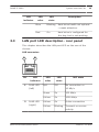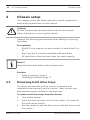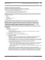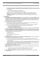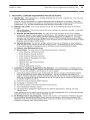
1
DIVAR IP 2000
DIP-2040EZ-00N, DIP-2042EZ-4HD, DIP-2042EZ-2HD
en
Installation Manual
DIVAR IP 2000
Table of Contents | en
3
Table of contents
1
Safety precautions
4
1.1
General safety precautions
4
1.2
Electrical safety precautions
7
1.3
ESD precautions
8
1.4
Operating precautions
2
Available documentation
10
3
System overview
11
3.1
Device views
11
3.2
LED description - front panel
14
3.3
LAN port LED description - rear panel
15
4
Chassis setup
16
4.1
Removing hard drive trays
16
4.2
Installing a hard drive
17
5
Installation - first steps
18
5.1
Setup notes
18
5.2
Connecting the unit
18
6
Obtainging a basic configuration
20
7
Advanced configuration
21
8
Maintaining the system
23
8.1
Monitoring the system
23
8.2
Recovering the unit
24
8.3
Backing up the configuration
25
8.4
Adding/replacing hard disks
26
8.4.1
Extending a 2-disk unit
26
8.4.2
Extending an empty unit
27
8.4.3
Replacing hard disks
27
8.5
Updating the system
28
8.6
Using the IP Helper tool
29
9
End-user license agreement (EULA)
30
Bosch Sicherheitssysteme GmbH
9
2014.07 | V1 | DOC
4
en | Safety precautions
DIVAR IP 2000
Safety precautions
1
Observe the safety precautions in this chapter.
1.1
General safety precautions
Follow these rules to ensure general safety:
–
Keep the area around the system clean and free of clutter.
–
Place the chassis top cover and any system components
that have been removed away from the system or on a table
so that they won't accidentally be stepped on.
–
While working on the system, do not wear loose clothing
such as neckties and unbuttoned shirt sleeves, which can
come into contact with electrical circuits or be pulled into a
cooling fan.
–
Remove any jewelry or metal objects from your body, which
are excellent metal conductors that can create short
circuits and harm you if they come into contact with printed
circuit boards or areas where power is present.
Warning!
Interruption of mains supply:
Voltage is applied as soon as the mains plug is inserted into the
!
mains socket.
However, for devices with a mains switch, the device is only
ready for operation when the mains switch (ON/OFF) is in the
ON position. When the mains plug is pulled out of the socket,
the supply of power to the device is completely interrupted.
2014.07 | V1 | DOC
Bosch Sicherheitssysteme GmbH
DIVAR IP 2000
Safety precautions | en
5
Warning!
Removing the housing:
To avoid electric shock, the housing must only be removed by
qualified service personnel.
!
Before removing the housing, the plug must always be removed
from the mains socket and remain disconnected while the
housing is removed. Servicing must only be carried out by
qualified service personnel. The user must not carry out any
repairs.
Warning!
Power cable and AC adapter:
When installing the product, use the provided or designated
!
connection cables, power cables and AC adaptors. Using any
other cables and adaptors could cause a malfunction or a fire.
Electrical Appliance and Material Safety Law prohibits the use
of UL or CSA-certified cables (that have UL/CSA shown on the
code) for any other electrical devices.
Warning!
Lithium battery:
Batteries that have been inserted wrongly can cause an
explosion. Always replace empty batteries with batteries of the
!
same type or a similar type recommended by the manufacturer.
Handle used batteries carefully. Do not damage the battery in
any way. A damaged battery may release hazardous materials
into the environment.
Dispose of empty batteries according to the manufacturer's
instructions.
Bosch Sicherheitssysteme GmbH
2014.07 | V1 | DOC
6
en | Safety precautions
DIVAR IP 2000
Warning!
!
Handling of lead solder materials used in this product may
expose you to lead, a chemical known to the State of California
to cause birth defects and other reproductive harm.
Notice!
Electrostatically sensitive device:
To avoid electrostatic discharges, the CMOS/MOSFET
protection measures must be carried out correctly.
When handling electrostatically sensitive printed circuits,
grounded anti-static wrist bands must be worn and the ESD
safety precautions observed.
Notice!
Installation should only be carried out by qualified customer
service personnel in accordance with the applicable electrical
regulations.
Disposal
Your Bosch product has been developed and
manufactured using high-quality materials and
components that can be reused.
This symbol means that electronic and electrical
devices that have reached the end of their working
life must be disposed of separately from
household waste.
In the EU, separate collecting systems are already
in place for used electrical and electronic
products. Please dispose of these devices at your
local communal waste collection point or at a
recycling center.
2014.07 | V1 | DOC
Bosch Sicherheitssysteme GmbH
DIVAR IP 2000
1.2
Safety precautions | en
7
Electrical safety precautions
Basic electrical safety precautions should be followed to protect
you from harm and the system from damage:
–
Be aware of the locations of the power on/off switch on the
chassis as well as the room's emergency power-off switch,
disconnection switch or electrical outlet. If an electrical
accident occurs, you can then quickly remove power from
the system.
–
Do not work alone when working with high voltage
–
Power should always be disconnected from the system
components.
when removing or installing main system components, such
as the motherboard or memory modules. When
disconnecting power, you should first turn off the system
and then unplug the power cords from all the power supply
modules in the system.
–
When working around exposed electrical circuits, another
person who is familiar with the power-off controls should
be nearby to switch off the power if necessary.
–
Use only one hand when working with powered-on
electrical equipment. This is to avoid making a complete
circuit, which will cause electrical shock. Use extreme
caution when using metal tools, which can easily damage
any electrical components or circuit boards they come into
contact with.
–
The power supply power cords must include a grounding
plug and must be plugged into grounded electrical outlets.
The unit has more than one power supply cord. Disconnect
both power supply cords before servicing to avoid electrical
shock.
–
Mainboard replaceable soldered-in fuses: Self-resetting PTC
(Positive Temperature Coefficient) fuses on the mainboard
must be replaced by trained service technicians only. The
Bosch Sicherheitssysteme GmbH
2014.07 | V1 | DOC
8
en | Safety precautions
DIVAR IP 2000
new fuse must be the same or equivalent as the one
replaced. Contact technical support for details and
support.
Caution!
Mainboard Battery: There is a danger of explosion if the
onboard battery is installed upside down, which will reverse its
!
polarities. This battery must be replaced only with the same or
an equivalent type recommended by the manufacturer
(CR2032). Dispose of used batteries according to the
manufacturer's instructions.
1.3
ESD precautions
Electrostatic Discharge (ESD) is generated by two objects with
different electrical charges coming into contact with each other.
An electrical discharge is created to neutralize this difference,
which can damage electronic components and printed circuit
boards. The following measures are generally sufficient to
neutralize this difference before contact is made to protect your
equipment from ESD:
–
Do not use mats designed to decrease electrostatic
discharge as protection from electrical shock. Instead, use
rubber mats that have been specifically designed as
electrical insulators.
–
Use a grounded wrist strap designed to prevent static
discharge.
–
Keep all components and printed circuit boards (PCBs) in
their antistatic bags until ready for use.
–
Touch a grounded metal object before removing the board
from the antistatic bag.
–
Do not let components or printed circuit boards come into
contact with your clothing, which may retain a charge even
if you are wearing a wrist strap.
2014.07 | V1 | DOC
Bosch Sicherheitssysteme GmbH
DIVAR IP 2000
–
Safety precautions | en
9
Handle a board by its edges only. Do not touch its
components, peripheral chips, memory modules or
contacts.
–
When handling chips or modules, avoid touching their pins.
–
Put the mainboard and peripherals back into their antistatic
bags when not in use.
–
For grounding purposes, make sure your computer chassis
provides excellent conductivity between the power supply,
the case, the mounting fasteners and the mainboard.
1.4
Operating precautions
The chassis cover must be in place when the system is operating
to assure proper cooling. Out of warranty damage to the system
can occur if this practice is not strictly followed.
Note:
Please handle used batteries carefully. Do not damage the
battery in any way. A damaged battery may release hazardous
materials into the environment. Do not discard a used battery in
the garbage or a public landfill. Please comply with the
regulations set up by your local hazardous waste management
agency to dispose of your used battery properly.
Bosch Sicherheitssysteme GmbH
2014.07 | V1 | DOC
10
2
en | Available documentation
DIVAR IP 2000
Available documentation
This manual is available in different languages. You can find all
manuals in the online product catalog.
Documentation for Bosch Security Systems products can be
found as follows:
4
Open any browser > enter www.boschsecurity.com > select
your region and your country > start a search for your
product > select the product in the search results to show
the existing documents.
2014.07 | V1 | DOC
Bosch Sicherheitssysteme GmbH
DIVAR IP 2000
3
System overview | en
11
System overview
The DIVAR IP 2000 system is an affordable, easy to use all-in-one
recording and management solution for network surveillance
systems of up to 16 channels. All channels are pre-licensed.
Running the full Bosch recording solution, DIVAR IP 2000 is an
intelligent IP storage device that provides both, a professional
video recording solution and ease of operation.
DIVAR IP 2000 is a 4-bay mini tower unit that combines
advanced management and state-of-the-art recording
management into a single cost-effective, plug and play IP
recording appliance for IT-minded customers which are seeking
for a “second generation” NVR recording solution.
DIVAR IP 2000 utilizes a highly energy efficient, embedded
design at a very affordable price which nevertheless boasts
Bosch quality through-and-through.
Easy to install and operate, DIVAR IP 2000 features wizardbased set-up and centralized configuration to reduce installation
times. All components are pre-installed and pre-configured.
Simply connect to the network and turn on the unit —
DIVAR IP 2000 is ready to begin recording straight out-of-thebox.
DIVAR IP 2000 features front-swappable SATA-II hard drives. All
system software is pre-installed and pre-activated — creating a
ready-to-use video recording appliance.
3.1
Device views
There are several LEDs on the front and rear of the chassis. The
LEDs show the over-all status of the system and the activity and
health of specific components.
Bosch Sicherheitssysteme GmbH
2014.07 | V1 | DOC
12
en | System overview
DIVAR IP 2000
Front view:
1
6
2
3
4
5
1
Lock for front cover
4
LAN activity LED
2
Power on/off LED
5
System status LED
3
Hard disk access LED
6
Individual hard disk LED
2014.07 | V1 | DOC
Bosch Sicherheitssysteme GmbH
DIVAR IP 2000
System overview | en
13
DIVAR IP rear view:
1
1
2
1x eSATA (not used)
3
4
4
5
6
2x USB 3.0
Note: Do not use.
2
1x Ethernet (RJ45)
5
1x VGA (monitor)
Note: Only for
troubleshooting.
3
2x USB 2.0
Note: Only for
6
Mains connection 100 240 VAC
troubleshooting.
Bosch Sicherheitssysteme GmbH
2014.07 | V1 | DOC
14
3.2
en | System overview
DIVAR IP 2000
LED description - front panel
This chapter describes the LED displays on the front of the
chassis.
LED
LED
LED
indicator
color
state
Power
LED
Description
N/A
Off
Power off
Blue
On
Working
(default)
HDD LED
LAN LED
System
N/A
Off
No disk access
Blue
Blinking
Disk access
N/A
Off
Network disconnected
Blue
On
Network connected
Blue
Blinking
Network activity
N/A
Off
System has booted in normal
LED
operation.
Blue
Blinking
System is booting or a
software update is being
applied.
Red
On
Undefined software error.
Contact technical support.
Individual
N/A
hard disk
LED
Off
No hard drive configured for
(default) this bay.
Blue
On
Hard drive present and
working.
2014.07 | V1 | DOC
Bosch Sicherheitssysteme GmbH
DIVAR IP 2000
System overview | en
LED
LED
LED
indicator
color
state
Blue
15
Description
Blinking
Hard drive health not optimal
— needs attention.
Red
On
Hard drive is configured for
this bay, but is not working.
3.3
LAN port LED description - rear panel
This chapter describes the LAN port LED on the rear of the
chassis.
LAN connector:
1
Nr.
1
2
LED
LED
LED
indicator
color
state
RJ45 LED
N/A
Off
(left)
2
RJ45 LED
(right)
NIC state
No connection or
10 Mb/s
Green
On
100 Mb/s
Yellow
On
1000 Mb/s
Yellow
On
Active connection
Yellow
Blinking
Transmit or receive
activity
Bosch Sicherheitssysteme GmbH
2014.07 | V1 | DOC
16
en | Chassis setup
DIVAR IP 2000
Chassis setup
4
This chapter covers the steps required to install components
and perform maintenance on the chassis.
Caution!
!
Review the warnings and precautions listed in the manual
before setting up or servicing this chassis.
Observe the following prerequisites when adding or replacing
hard disks.
Prerequisites:
–
DIVAR IP only supports an even number of hard disks (2 or
4)
–
Bay 1 and bay 2 must be populated with hard disks
–
All hard disks of the unit must have the same capacity
Notice!
Insert the hard disks before initial system start.
See also:
4.1
–
Safety precautions, page 4
–
Installing a hard drive, page 17
Removing hard drive trays
The drives are mounted in drive carriers to simplify their
installation and removal from the chassis. These carriers also
help promote proper airflow for the drive bays.
To remove hard drive trays from the chassis:
1.
Turn off the system.
2.
Press the release button on the drive carrier. This extends
the drive carrier handle.
3.
Use the handle to pull the drive carrier with the drive out of
the chassis.
2014.07 | V1 | DOC
Bosch Sicherheitssysteme GmbH
DIVAR IP 2000
4.
Chassis setup | en
17
Insert the drive carrier with the new drive into the chassis
bay, making sure that the drive carrier handle is completely
closed.
Notice!
Except for short periods of time, do not operate the unit with
the hard drives removed from the bays.
4.2
Installing a hard drive
The drives are mounted in drive carriers.
To install a hard drive to the hard drive carrier:
1.
Remove the drive from the carrier.
2.
Install a new drive into the carrier with the printed circuit
board side facing down so that the mounting holes align
with those in the carrier.
3.
Replace the drive carrier into the chassis bay, making sure
that the drive carrier handle is completely closed.
Notice!
We recommend using the respective Bosch hard disk drives.
The hard disk drives as one of the critical component are
carefully selected by Bosch based on available failure rates.
HDD – not delivered from Bosch – are not supported.
Information on supported HDDs can be found in the datasheet
in the Bosch Online Product Catalog.
Bosch Sicherheitssysteme GmbH
2014.07 | V1 | DOC
18
5
en | Installation - first steps
DIVAR IP 2000
Installation - first steps
DIVAR IP systems are shipped with a pre-installed Configuration
Wizard from factory.
5.1
Setup notes
By default all DIVAR IP systems are configured to obtain a valid
network address from DHCP server in the local network. In
small networks this task is usually performed by an internet
router. If there is no DHCP server in the network, DIVAR IP will
use the following network settings:
–
IP Address: 192.168.0.200
–
Subnet mask: 255.255.255.0
Notice!
We strongly recommend that you do not change any operating
system settings. Operating system access should only be used
for troubleshooting. Changes can result in malfunctioning of the
system.
5.2
Connecting the unit
DIVAR IP system is ready to go out of the box. The application
provides a simple to install and intuitive to use solution for
network surveillance systems.
Connecting the unit:
1.
Connect the unit and the cameras to the network.
2.
Connect the unit to the power supply.
3.
Turn on the unit.
A series of scripts perform important setup tasks. This can
take several minutes. Do not turn off the computer.
Note: During this initial setup the system LED is blinking.
After the system is ready for operation, the system LED
stops blinking. The web based wizard pages of the DIVAR IP
2014.07 | V1 | DOC
Bosch Sicherheitssysteme GmbH
DIVAR IP 2000
Installation - first steps | en
19
can now be accessed from any browser within the network.
Use this web page wizard pages to obtain a basic system
configuration.
See also:
–
Device views, page 11
–
Obtainging a basic configuration, page 20
Bosch Sicherheitssysteme GmbH
2014.07 | V1 | DOC
20
6
en | Obtainging a basic configuration
DIVAR IP 2000
Obtainging a basic configuration
DIVAR IP 2000 offers an easy-to-use configuration wizard to
obtain quickly a basic configuration of a smaller system.
To achieve a basic configuration using the Configuration Wizard:
1.
Open a web browser from any PC in the network, enter the
IP address of DIVAR IP in the address bar, then press
ENTER. The Welcome page of the Configuration Wizard is
displayed.
Note:
If you do not know the IP address, proceed as follows:
–
Only one DIVAR IP 2000 is in the network:
Enter http://mydivar or https://mydivar, then
press ENTER. The Welcome page of the Configuration
Wizard is displayed.
!! Use mydivar only if there is one DIVAR IP in the
same network, not if there are multiple DIVAR IP.!!
–
Multiple DIVAR IP 2000 are in the same network:
Use the IP Helper tool to display all devices with their
IP addresses. The tool is available in the online catalog
on the DIVAR IP 2000 product page.
2.
On the Welcome page select your preferred language, then
click Start configuration.
3.
Run-through the wizard and follow the instructions. Each
page provides you with information how to use it.
4.
After finishing the Configuration Wizard your system has a
basic configuration available. If the basic configuration
needs to be extended, use the advanced configuration.
See also:
–
Using the IP Helper tool, page 29
–
Advanced configuration, page 21
2014.07 | V1 | DOC
Bosch Sicherheitssysteme GmbH
DIVAR IP 2000
7
Advanced configuration | en
21
Advanced configuration
The advanced configuration allows you to configure the system
to your needs.
To use the advanced configuration:
1.
Open a web browser from any PC in the network.
2.
In the address bar of the web browser, enter http://
mydivar/configurationsite or http://<IP address
of DIVAR IP>/configurationsite, then press ENTER.
The configuration is displayed.
Note: If the DIVAR IP user interface is already open, click
the Configuration tab.
3.
Select the desired page in the tree structure to the right
where to make the changes.
–
Video devices page
Adding and removing devices
Defining the motion detection settings
–
Recording page
Defining phases
Assigning properties to phases
–
Alarms page
Defining scenarios
Adding and deleting actions
Configuring e-mail properties
–
Remote access page
Selecting a dynamic DNS provider
Testing the connections to DIVAR IP 2000
–
System page
Creating accounts
Defining the storage mode
Setting password
Setting time zone, date and time
Selecting the language
Maintaining the system
4.
Make the changes and save the configuration.
Bosch Sicherheitssysteme GmbH
2014.07 | V1 | DOC
22
en | Advanced configuration
DIVAR IP 2000
Notice!
Use the help that is available for each page.
See also:
–
Obtainging a basic configuration, page 20
–
Monitoring the system, page 23
–
Using the IP Helper tool, page 29
2014.07 | V1 | DOC
Bosch Sicherheitssysteme GmbH
DIVAR IP 2000
Maintaining the system | en
8
Maintaining the system
8.1
Monitoring the system
23
DIVAR IP 2000 Dashboard is used to monitor the status of a
DIVAR IP 2000 system from any PC in the network.
DIVAR IP 2000 Dashboard provides information on the DIVAR IP
2000 system.
You cannot configure DIVAR IP 2000 with DIVAR IP 2000
Dashboard. To configure the system, use the Configuration
Wizard first to obtain a basic configuration, then (if necessary)
open the Configuration menu for advanced configuration.
To use DIVAR IP 2000 Dashboard:
1.
Open a web browser from any PC in the network.
2.
In the address bar of the web browser, enter http://
mydivar/dlacockpit or http://<IP address of DIVAR
IP>/dlacockpit, then press ENTER. The DIVAR IP 2000
Dashboard is displayed.
Note: If the DIVAR IP user interface is already open, click
the Dashboard tab.
3.
Select the desired page in the tree structure to the right
where to obtain system information.
–
System information page
Displays status and hard drive information (for
example, number of cameras, hard drive status).
–
Logbook page
–
Device monitor page
Displays logbook information.
Displays all connected devices.
Offers a Update manually... button to update the
system software.
Notice!
Use the help that is available for each page.
Bosch Sicherheitssysteme GmbH
2014.07 | V1 | DOC
24
en | Maintaining the system
DIVAR IP 2000
See also:
8.2
–
Obtainging a basic configuration, page 20
–
Advanced configuration, page 21
Recovering the unit
Following procedure describes how to restore the factory
default image.
Notice!
Before recovering DIVAR IP we recommend backing up the
configuration.
To restore the unit to factory default image
1.
Start the unit and press F7 during the BIOS power-on-selftest.
The Recovery menu is displayed.
Notice!
Make sure that a VGA monitor, a keyboard and a mouse are
connected to the unit.
2.
Select one of the following:
–
Initial to factory image (all data will be deleted)
(restores to factory default image and deletes all data
on the HDDs)
or
–
Restore to Factory image (all data will not be
deleted)
(restores to factory default image; data on the HDDs
will not be deleted)
Note:
Windows performs the setup. The screen displays the
percentage of the process.
2014.07 | V1 | DOC
Bosch Sicherheitssysteme GmbH
DIVAR IP 2000
Maintaining the system | en
25
Notice!
Do not turn off the unit during the process. This will damage
the Recovery media.
3.
The unit starts from the Recovery media. If the setup is
successful, press Yes to restart the system.
4.
Windows performs the initial setup of the operating system.
The unit restarts after Windows has completed the setup.
5.
After the restart of the unit, the factory settings are
installed.
See also:
–
8.3
Backing up the configuration, page 25
Backing up the configuration
Following procedure describes how to back up the
configuration.
Notice!
We recommend backing up the configuration frequently so that
recent backups are always available if required.
To back up the configuration:
1.
In the DIVAR IP configuration, expand System, then click
Service.
2.
To back up the configuration, click Back up. A dialog box is
displayed.
3.
Click Save. Where the configuration is saved depends on
the browser settings.
Note: If you want to select a specific target directory for
the backup file, click the arrow to the right of the Save
button, then click Save as.
4.
To find the backup, click the Windows Start button, enter
downloads in the search box, then press ENTER.
A dialog box containing the backup file is displayed.
Bosch Sicherheitssysteme GmbH
2014.07 | V1 | DOC
26
en | Maintaining the system
8.4
DIVAR IP 2000
Adding/replacing hard disks
Observe the following prerequisites when adding or replacing
hard disks.
Prerequisites:
–
DIVAR IP only supports an even number of hard disks (2 or
4)
–
Bay 1 and bay 2 must be populated with hard disks
–
All hard disks of the unit must have the same capacity
Notice!
Insert the hard disks before initial system start.
8.4.1
Extending a 2-disk unit
You can extend a 2-disk unit with 2 additional hard disks.
To add hard disks to a 2-disk unit:
1.
2.
Turn off the unit by pressing the power button.
Insert the new hard disks into the chassis bay, making sure
that the drive carrier handle is completely closed.
3.
Turn on the unit by pressing the power button.
4.
Open DIVAR IP Dashboard with any browser. To do this, in
the address bar of the web browser, enter http://
mydivar/dlacockpit or http://<IP address of DIVAR
IP>/dlacockpit, then press ENTER. DIVAR IP 2000
Dashboard displays the message that you must open
Configuration > Disk management for configuration.
5.
Click Configuration to open the configuration.
6.
Expand System, then click Disk management.
7.
To add the storage capacity of the hard disks to the system,
follow the instructions that are displayed.
8.
After finishing the hard disk setup the individual disk status
LED to the right of the disk carrier will turn blue.
2014.07 | V1 | DOC
Bosch Sicherheitssysteme GmbH
DIVAR IP 2000
Maintaining the system | en
27
See also:
–
8.4.2
Chassis setup, page 16
Extending an empty unit
You can extend an empty unit with 2 or 4 additional hard disks.
To add hard disks to an empty unit:
1.
Insert the new hard disks into the chassis bay, making sure
that the drive carrier handle is completely closed.
2.
Turn on the unit by pressing the power button.
3.
The unit identifies the hard disks as new and starts the
recovery menu automatically.
After finishing the recovery process the DIVAR IP software
is installed. The individual disk status LED to the right of
the disk carrier will turn blue.
4.
Perform a basic configuration using the configuration
wizard.
See also:
8.4.3
–
Chassis setup, page 16
–
Obtainging a basic configuration, page 20
Replacing hard disks
If a hard disk fails, the individual disk status LED to the right of
the disk carrier will turn red.
To replace hard disks:
1.
Remove the defective hard disk. Use the handle to pull the
disk carrier out of the chassis.
Note: You can remove the hard disk during operation.
2.
3.
Turn off the unit by pressing the power button.
Insert the new hard disks into the chassis bay, making sure
that the drive carrier handle is completely closed.
4.
Turn on the unit by pressing the power button.
5.
Open DIVAR IP Dashboard with any browser. To do this, in
the address bar of the web browser, enter http://
mydivar/dlacockpit or http://<IP address of DIVAR
Bosch Sicherheitssysteme GmbH
2014.07 | V1 | DOC
28
en | Maintaining the system
DIVAR IP 2000
IP>/dlacockpit, then press ENTER. DIVAR IP 2000
Dashboard displays the message that you must open
Configuration > Disk management for configuration.
6.
Click Configuration to open the configuration.
7.
Expand System, then click Disk management.
8.
To add the storage capacity of the hard disks to the system,
follow the instructions that are displayed.
9.
After finishing the hard disk setup the individual disk status
LED to the right of the disk carrier will turn blue.
See also:
–
8.5
Chassis setup, page 16
Updating the system
Following procedure describes how to update the system
manually.
To update DIVAR IP manually:
1.
In DIVAR IP Dashboard, click Device monitor in the tree
structure.
2.
Click Update manually.
A dialog box is displayed where you can browse for the
update file.
Notice!
If your system is connected to the internet, the system is
automatically checking for updates. If an update is available,
you can download and install it directly. If your system is not
connected to the internet, you can manually download the
latest update package from the product pages. Updating your
system includes all components as well as camera devices.
Updating will take about 5 - 10 minutes and recodings are
stopped during the update process.
2014.07 | V1 | DOC
Bosch Sicherheitssysteme GmbH
DIVAR IP 2000
8.6
Maintaining the system | en
29
Using the IP Helper tool
The IP Helper from Bosch is a small windows tool that allows
users to view all IP devices with their IP addresses located in a
network. With this tool user can find IP addresses of IP devices
or configure the network settings of the IP devices in a quick
and easy way without having expert knowledge. The IP Helper is
a directly executable program, no installation is necessary. You
can use any PC in the network to open IP Helper. Opening IP
Helper directly from a USB stick is possible.
The IP Helper tool is available for download as follows:
–
in the online catalog on the DIVAR IP 2000 product page
–
under http://mydivar.com
To find DIVAR IP systems:
1.
Double-click the IP Helper tool (iphelper.exe).
2.
A dialog box opens that displays all IP devices with their IP
addresses located in the network. Search for the DIVAR IP
system you want to configure and note the IP address.
Note: To identify a DIVAR IP system, press Blink LED.
Bosch Sicherheitssysteme GmbH
2014.07 | V1 | DOC
30
9
en | End-user license agreement (EULA)
DIVAR IP 2000
End-user license agreement (EULA)
This chapter informs you about the Microsoft License Terms for
Microsoft Windows Storage Server 2008 R2 Standard.
Please read the following pages carefully.
2014.07 | V1 | DOC
Bosch Sicherheitssysteme GmbH
DIVAR IP 2000
Bosch Sicherheitssysteme GmbH
End-user license agreement (EULA) | en
31
2014.07 | V1 | DOC
32
en | End-user license agreement (EULA)
2014.07 | V1 | DOC
DIVAR IP 2000
Bosch Sicherheitssysteme GmbH
DIVAR IP 2000
Bosch Sicherheitssysteme GmbH
End-user license agreement (EULA) | en
33
2014.07 | V1 | DOC
34
en | End-user license agreement (EULA)
2014.07 | V1 | DOC
DIVAR IP 2000
Bosch Sicherheitssysteme GmbH
DIVAR IP 2000
Bosch Sicherheitssysteme GmbH
End-user license agreement (EULA) | en
35
2014.07 | V1 | DOC
36
en | End-user license agreement (EULA)
2014.07 | V1 | DOC
DIVAR IP 2000
Bosch Sicherheitssysteme GmbH
DIVAR IP 2000
Bosch Sicherheitssysteme GmbH
End-user license agreement (EULA) | en
37
2014.07 | V1 | DOC
38
en | End-user license agreement (EULA)
2014.07 | V1 | DOC
DIVAR IP 2000
Bosch Sicherheitssysteme GmbH
Bosch Sicherheitssysteme GmbH
Robert-Bosch-Ring 5
85630 Grasbrunn
Germany
www.boschsecurity.com
© Bosch Sicherheitssysteme GmbH,
2014