1
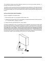
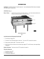
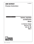
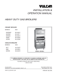
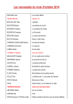
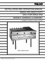
INSTALLATION AND OPERATION MANUAL
MAGIC-FIN HEAVY DUTY
GAS CHAR BROILERS
MODELS GHMCB34 & GHMCB51
FORMERLY MODELS M7806 & M7809
MODEL GHMCB34 SHOWN
VULCAN-HART COMPANY, P.O. BOX 696, LOUISVILLE, KY 40201- 0696, TEL. (502) 778-2791
FORM 30851 (3-94) (Formerly 114586 & 114587)
IMPORTANT FOR YOUR SAFETY
THIS MANUAL HAS BEEN PREPARED FOR PERSONNEL QUALIFIED TO INSTALL GAS
EQUIPMENT, WHO SHOULD PERFORM THE INITIAL FIELD START-UP AND
ADJUSTMENTS OF THE EQUIPMENT COVERED BY THIS MANUAL.
POST IN A PROMINENT LOCATION THE INSTRUCTIONS TO BE FOLLOWED IN THE
EVENT THE SMELL OF GAS IS DETECTED. THIS INFORMATION CAN BE OBTAINED
FROM THE LOCAL GAS SUPPLIER.
IMPORTANT
IN THE EVENT A GAS ODOR IS DETECTED, SHUT
DOWN UNITS AT MAIN SHUTOFF VALVE AND
CONTACT THE LOCAL GAS COMPANY OR GAS
SUPPLIER FOR SERVICE.
FOR YOUR SAFETY
DO NOT STORE OR USE GASOLINE OR OTHER
FLAMMABLE VAPORS OR LIQUIDS IN THE
VICINITY OF THIS OR ANY OTHER APPLIANCE.
WARNING
IMPROPER INSTALLATION, ADJUSTMENT,
ALTERATION OR MODIFICATION, SERVICE OR
MAINTENANCE CAN CAUSE PROPERTY
DAMAGE, INJURY OR DEATH. READ THE
INSTALLATION, OPERATING AND MAINTENANCE
INSTRUCTIONS THOROUGHLY BEFORE
INSTALLING OR SERVICING THIS EQUIPMENT.
IN THE EVENT OF A POWER FAILURE, DO NOT
ATTEMPT TO OPERATE THIS DEVICE.
-2-
TABLE OF CONTENTS
GENERAL. . . . . . . . . . . . . . . . . . . . . . . . . . . . . . . . . . . . . . . . . . . . . . . . . . . . . . . . . . . . . . . . . . . . . . 4
INSTALLATION . . . . . . . . . . . . . . . . . . . . . . . . . . . . . . . . . . . . . . . . . . . . . . . . . . . . . . . . . . . . . . . . . 4
Unpacking . . . . . . . . . . . . . . . . . . . . . . . . . . . . . . . . . . . . . . . . . . . . . . . . . . . . . . . . . . . . . . . . 4
Location . . . . . . . . . . . . . . . . . . . . . . . . . . . . . . . . . . . . . . . . . . . . . . . . . . . . . . . . . . . . . . . . . 4
Installation Codes and Standards . . . . . . . . . . . . . . . . . . . . . . . . . . . . . . . . . . . . . . . . . . . . . 5
Leveling and Connecting Manifolds . . . . . . . . . . . . . . . . . . . . . . . . . . . . . . . . . . . . . . . . . . . 6
Gas Connections . . . . . . . . . . . . . . . . . . . . . . . . . . . . . . . . . . . . . . . . . . . . . . . . . . . . . . . . . . 7
Testing the Gas Supply System . . . . . . . . . . . . . . . . . . . . . . . . . . . . . . . . . . . . . . . . . . . . . . 8
Flue Connections . . . . . . . . . . . . . . . . . . . . . . . . . . . . . . . . . . . . . . . . . . . . . . . . . . . . . . . . . . 8
OPERATION . . . . . . . . . . . . . . . . . . . . . . . . . . . . . . . . . . . . . . . . . . . . . . . . . . . . . . . . . . . . . . . . . . . 9
Controls . . . . . . . . . . . . . . . . . . . . . . . . . . . . . . . . . . . . . . . . . . . . . . . . . . . . . . . . . . . . . . . . . 9
Lighting and Shutdown Instructions . . . . . . . . . . . . . . . . . . . . . . . . . . . . . . . . . . . . . . . . . . . 9
Preheating . . . . . . . . . . . . . . . . . . . . . . . . . . . . . . . . . . . . . . . . . . . . . . . . . . . . . . . . . . . . . . 10
Grid Tops . . . . . . . . . . . . . . . . . . . . . . . . . . . . . . . . . . . . . . . . . . . . . . . . . . . . . . . . . . . . . . . 10
Grease Collector Tray . . . . . . . . . . . . . . . . . . . . . . . . . . . . . . . . . . . . . . . . . . . . . . . . . . . . . 10
Cleaning . . . . . . . . . . . . . . . . . . . . . . . . . . . . . . . . . . . . . . . . . . . . . . . . . . . . . . . . . . . . . . . . 10
MAINTENANCE . . . . . . . . . . . . . . . . . . . . . . . . . . . . . . . . . . . . . . . . . . . . . . . . . . . . . . . . . . . . . . . . 12
Vent . . . . . . . . . . . . . . . . . . . . . . . . . . . . . . . . . . . . . . . . . . . . . . . . . . . . . . . . . . . . . . . . . . . . 12
Service and Parts Information . . . . . . . . . . . . . . . . . . . . . . . . . . . . . . . . . . . . . . . . . . . . . . . 12
-3-
Installation, Operation and Care of
MAGIC-FIN HEAVY DUTY GAS CHAR BROILERS
MODELS GHMCB34 & GHMCB51
KEEP THESE INSTRUCTIONS
GENERAL
The manufacturer suggests that you thoroughly read this entire manual and carefully follow all of the
instructions provided.
Your Vulcan Gas Char Broiler is produced with quality workmanship and material. Proper installation,
usage and maintenance of your broiler will result in many years of satisfactory performance.
INSTALLATION
UNPACKING
This char broiler was inspected before leaving the factory. The transportation company assumes full
responsibility for safe delivery upon acceptance of the shipment. Immediately after unpacking, check
for possible shipping damage. If the broiler is found to be damaged, save the packaging material and
contact the carrier within 15 days of delivery.
Remove all shipping wire, wood blocking, top grid grates, burner radiants, burners, manifold cover,
grease collector tray and lower panel.
Before installing, verify that the type of gas supply (natural or propane) agrees with the specifications
on the rating plate which is located on the lower front panel. If the supply and equipment requirements
do not agree, do not proceed with the installation. Contact your dealer or Vulcan-Hart immediately.
LOCATION
This char broiler is for use in non-combustible locations ONLY! The equipment must be kept clear of
any combustible constructions or substances.
-4-
The installation location must allow adequate clearances for servicing and proper operation. A
minimum front clearance of 36" is required.
The broiler must be installed so that the flow of combustion and ventilation air will not be obstructed.
Adequate clearance for air openings into the combustion chamber must be provided. Make sure there
is an adequate supply of air in the room suitable for the amount of combustion gas feeding the broiler
burners.
INSTALLATION CODES AND STANDARDS
Install this equipment in accordance with:
1. State and local codes, or in the absence of local codes, with:
2. National Fuel Gas Code, ANSI-Z223.1 (latest edition), available from the American Gas Association,
Inc., 1515 Wilson Blvd., Arlington, VA 22209.
3. National Electrical Code ANSI/NFPA 70 (latest edition).
For broilers equipped with casters, the installation shall be made with a connector that complies with
the Standard for Connectors for Movable Gas Appliances, ANSI Z21.69 (latest edition), and a quickdisconnect device that complies with the Standard for Quick-Disconnect Devices for Use With Gas
Fuel, ANSI Z21.41 (latest edition). Provide a gas line strain relief to limit movement of the broiler
without depending on the connector and any quick-disconnect device or its associated piping to limit
the broiler movement. Attach the strain relief to the rear of the broiler (Fig. 1). Should it be necessary
to disconnect the restraint, turn off the gas supply before disconnection. Reconnect the restraint before
turning the gas supply on and returning the char broiler to its installation position.
CONNECT GAS
LINE STRAIN
RELIEF HERE
Fig. 1
-5-
PL-51216
LEVELING AND CONNECTING MANIFOLDS
1. Place the broiler in the exact position it is to occupy. If the broiler is to be used in a battery, it is
recommended that it be installed on either end of the battery due to the intense heat and the need
for adequate ventilation. The broiler may NOT be installed next to a deep fat fryer.
2. Using a carpenter's level, level the broiler from front to rear and from side to side. Unless the broiler
is level, it will be difficult to line up the manifold piping, and appliances will not butt tightly.
3. Effective January 4, 1994, Vulcan-Hart Company is in the process of changing gas pipe union
vendors from Flagg to Stockham on all gas heavy duty appliances. During this changeover, there
will be three possible conditions of installation. Please read the information below carefully to
determine the correct installation procedure for your appliance.
a. Broilers with square front tops are now shipped with Stockham gas manifold pipe unions. When
batterying a squared front top appliance with a heavy duty appliance built prior to January 4,
1994, remove the old style Flagg union fitting of the existing field appliance (Fig. 2) from the
manifold pipe and replace it with a Stockham union (Fig. 3).
b. Broilers with rounded front top using the Stockham fitting (Fig. 3) will also require the changeout
described in Item (a). In this event, you will receive two unions. One union will be installed on
the new appliance manifold pipe and one will be packaged unmounted in the oven, broiler or
cabinet base compartments (depending on models). Remove the Flagg union (Fig. 2) from the
existing field appliance and replace it with the prepackaged Stockham union (Fig. 3) before
installing the new appliance.
c. Broilers with rounded front tops shipped with one Flagg union (Fig. 2) will not require the above
changeout.
Questions or concerns regarding the above installation procedures may be addressed by calling
the Vulcan-Hart Service Department (502) 778-2791.
PL-40072
PL-40073
Fig. 2
Fig. 3
-6-
4. Engage union nut on manifold pipe with male fitting on next appliance and draw union hand tight.
Be sure broilers butt both front and rear.
5. If manifolds do not line up, units are not level.
6. If the broiler is installed on the end of the battery and the top of the front top does not line up with
the adjacent unit, adjust front tops by means of bolts on the underside before replacing the manifold
cover and installing the valve handles.
7. Continue to level up and connect manifold pipe until all appliances in the battery are connected.
Then tighten manifold unions gas tight.
GAS CONNECTIONS
All gas supply connections and any pipe joint compound used must be resistant to the action of propane
gases.
Connect gas supply to the broiler(s). Make sure the pipes are clean and free of obstructions, dirt, and
piping compound.
Codes require that a gas shutoff valve be installed in the gas line ahead of the broiler.
Natural gas broilers and propane gas broilers are equipped with fixed orifices and no adjustment is
necessary.
The gas manifold of this broiler, or battery of which it is a part, must be connected to a pressure
regulator (not supplied) with a preset outlet pressure of 6" W.C. (Water Column) for natural gas or 10"
W.C. for propane gas. The regulators must have:
•
•
•
A.G.A. design certification.
Enough regulation capacity for the total connected gas load.
Pressure adjustment range to allow adjustment for the manifold pressure marked on the rating
plate.
Unless the manifold pressure on all connected broilers is the same, a separate regulator must be
supplied for each broiler having different manifold pressures.
Be sure all burner and pilot valves are in a closed position.
Turn on gas supply and check for leaks.
WARNING: PRIOR TO LIGHTING, CHECK ALL JOINTS IN THE GAS SUPPLY LINE FOR LEAKS.
USE SOAP AND WATER SOLUTION. DO NOT USE AN OPEN FLAME.
After piping has been checked for leaks, all piping receiving gas should be fully purged to remove air.
Ensure that burner heads are connected.
Adjust burners making sure they line up with burner nozzles and that all burner baffle plates are
hanging in the proper position.
-7-
TESTING THE GAS SUPPLY SYSTEM
When test pressures exceed 1/2 psig (3.45 kPa), the broiler and its individual shutoff valve must be
disconnected from the gas supply piping system.
When test pressures are 1/2 psig (3.45 kPa) or less, the broiler must be isolated from the gas supply
system by closing its individual manual shutoff valve.
FLUE CONNECTIONS
DO NOT obstruct the flow of flue gases from the flue duct located on the rear of the broiler. It is
recommended that the flue gases be ventilated to the outside of the building through a ventilation
system installed by qualified personnel.
From the termination of the broiler flue vent to the filters of the hood venting system, an 18" minimum
clearance must be maintained.
Information on the construction and installation of ventilating hoods may be obtained from the standard
for "Vapor Removal from Cooking Equipment," NFPA No. 96 (latest edition), available from the
National Fire Protection Association, Batterymarch Park, Quincy, MA 02269.
-8-
OPERATION
WARNING: THE BROILER AND ITS PARTS ARE HOT. USE CARE WHEN OPERATING, CLEANING
OR SERVICING THE BROILER.
CONTROLS (Fig. 4)
Burner Valves — regulate the gas flow to the broiler burners. Turn knob counterclockwise to
increase flame and clockwise to decrease flame.
Reversible Grid Tops
Burner Valves
Grease Collector
Tray
PL-40164-1
Model GHMCB34 Shown
Fig. 4
LIGHTING AND SHUTDOWN INSTRUCTIONS
1. Turn main gas supply ON.
2. Turn burner valve ON and purge air from lines. Turn valve OFF and wait five minutes.
3. Using a taper, light the pilot. Turn burner valve ON.
4. If pilot fails to light, turn burner valve and main gas supply OFF, wait 5 minutes, and repeat Steps
1 through 3.
Nightly Shutdown: Turn burner valve OFF; the pilot will remain lit.
Extended Shutdown
1. Turn burner valve OFF.
2. Extinguish pilot light.
3. Turn main gas supply OFF.
-9-
PREHEATING
1. Turn burner valves to the HI position and allow 30-35 minutes for preheating. After this period of
preheating time, grid temperatures should be in the ideal range for the most favorable cooking
results (around 600°F).
2. Turn burner valve to the LO position (which is preset at the factory) to maintain grid temperatures
between 575°F and 625°F, which will provide ideal cooking conditions and the optimum finished
product.
DO NOT leave the burner valves set in the HI position, except for cleaning grid grates, for any extended
period of time beyond the recommended preheating time; it will produce grid temperatures in excess
of 1000°F. These temperatures will result in unfavorable cooking conditions, excessive carbonization
of grease on the grid and a poor tasting product. Excessive temperatures will also lead to premature
failure of the radiants and grid tops.
GRID TOPS
The GHMCB34 and GHMCB51 are equipped with reversible grids (see Fig. 4). The grids may be
placed on one side so that they are sloped and lifted away from the burner flame, or placed flat on the
broiler so that they are close to the burner flame.
WARNING: GRID TOPS ARE HOT. USE CARE WHEN CHANGING GRID TOP POSITIONS.
GREASE COLLECTOR TRAY
Periodically check and empty the grease collector tray (see Fig. 4) to avoid overflow of grease. To
remove tray, pull grease tray handle straight out, empty and replace tray.
CLEANING
Burner Radiant
Clean the burner radiants daily with a good wire brush. The radiants may be cleaned in place over the
burners, or they may be removed for a more thorough cleaning.
Burner Performance
If after a period of satisfactory operation burner flame characteristics should change or length of flame
should be reduced, either the mixer opening, the gas orifice or the burner ports have become restricted.
Clean burners every 60 days or more often if required. To clean burners, boil in a strong solution of
lye water for about 15 minutes. Ports can be opened by hand with a sharp pointed metal instrument
or a proper sized drill bit.
Enamel Finished Surface Parts
Clean using a cloth with detergent solution. Rinse thoroughly and wipe dry with a soft clean cloth.
- 10 -
Stainless Steel
When scraping off heavy deposits of grease or oil from stainless steel equipment, never use ordinary
steel scrapers and knives. Particles of ordinary steel may become embedded in, or lodge on, the
surface of the stainless steel. These will rust, causing unsightly stains. Where it is necessary to scrape,
use stainless steel, wood, plastic or rubber tools.
Clean exterior finish of equipment with a mild soap solution or similar grease dissolving material. If this
is done every day, before grease is burned on, time and work will be saved.
For routine cleaning of stainless steel, use ordinary soap or detergent and water. To prevent water
spots and streaks, rinse equipment thoroughly with warm water and wipe dry with a soft clean cloth.
Addition of a rinsing agent will also help prevent spotting.
Stubborn spots or stains that resist soap and water usually can be removed with a paste made of water
and mild scouring powder. When applying these powders, be sure to rub in the direction of the polish
lines on the steel to preserve the original finish.
Fingerprints are sometimes a problem on highly polished surfaces of stainless steel. They can be
minimized by applying a cleaner that will leave a thin oily or waxy film. To use these cleaners, simply
wipe on and remove excess with a soft dry cloth. After using, subsequent fingerprints will usually
disappear when wiped lightly with a soft dry cloth or with a cloth containing a little of the cleaner. If the
surface is especially dirty to start with, wash first with soap or detergent and water, rinse thoroughly
and wipe dry with a soft clean cloth.
In and around broilers where temperatures reach 500°F or more, straw-colored or slightly darkened
areas may appear on stainless steel. This "heat tint" is caused by a slight oxidation of the stainless
steel and is not harmful. To control or minimize this condition, never use more heat than is absolutely
necessary. Heat tint can be removed by scouring vigorously with stainless steel wool and a paste made
of a scouring powder. Again, remember to rub in the direction of the polish lines. Some prefer special
heat tint remover designed for use with stainless steel.
Soaking with hot soapy water will help greatly to remove burned-on foods and grease. Stubborn
deposits can be removed with scouring powder mixed into a paste and applied with stainless steel wool
or sponges. Remember to rub in the direction of the polish lines.
- 11 -
MAINTENANCE
WARNING: THE BROILER AND ITS PARTS ARE HOT. USE CARE WHEN OPERATING, CLEANING
OR SERVICING THE BROILER.
VENT
Annually check the hood venting system and appliance flue to ensure they are free of obstructions. Be
sure appliance is cool to the touch before making any hood or flue checks.
SERVICE AND PARTS INFORMATION
To obtain service and parts information concerning the Model GHMCB34/ GHMCB51 Gas Char Broiler,
contact the Vulcan-Hart Service Depot in your area (refer to the listing supplied with the broiler), or
Vulcan-Hart Company Service Department at the address or phone number shown on the front cover
of this manual.
FORM 30851 (3-94) (Formerly 114586 & 114587)
- 12 -
PRINTED IN U.S.A.