1
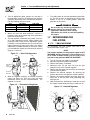
Parts, Adjustment and Maintenance Manual Air-cooled, Prepackaged Automatic Standby Generators Models: ASPAS1CCA007 (6 kW NG, 7 kW LP) ASPAS1CCA012 (12 kW NG, 12 kW LP) ASPAS1CCA015 (13 kW NG, 15 kW LP) US C LISTED GENERAC R POWER SYSTEMS, INC. R ! Not intended for use as Primary Power in place of utility or in life-support applications. DANGER DEADLY EXHAUST FUMES. OUTDOOR INSTALLATION ONLY!! ! INTRODUCTION This Carrier model is a compact, high performance, air-cooled, engine-driven generator designed to automatically supply electrical power to operate critical loads during a utility power failure. This unit is factory installed in an all-weather, metal enclosure that is intended exclusively for outdoor installation. This generator will operate using either vapor withdrawn liquid propane (LP) or natural gas (NG). READ THIS MANUAL THOROUGHLY Throughout this publication, and on tags and decals affixed to the generator, DANGER, WARNING, CAUTION and NOTE blocks are used to alert personnel to special instructions about a particular operation that may be hazardous if performed incorrectly or carelessly. Observe them carefully. Their definitions are as follows: DANGER After this heading, read instructions that, if not strictly complied with, will result in serious personal injury, including death, in addition to property damage. After this heading, read instructions that, if not strictly complied with, may result in serious personal injury or property damage. After this heading, read instructions that, if not strictly complied with, could result in damage to equipment and/or property. NOTE: After this heading, read explanatory statements that require special emphasis. These safety warnings cannot eliminate the hazards that they indicate. Common sense and strict compliance with the special instructions while performing the service are essential to preventing accidents. Four commonly used safety symbols accompany the DANGER, WARNING and CAUTION blocks. The type of information each indicates follows: This symbol points out important safety ! information that, if not followed, could endanger personal safety and/or property of others. This symbol points out potential explosion hazard. This symbol points out potential fire hazard. This symbol points out potential electrical shock hazard. Carrier The operator is responsible for proper and safe use of the equipment. Carrier strongly recommends that the dealer read this Parts, Adjustment and Maintenance Manual and thoroughly understand all instructions before using this equipment. Carrier also strongly recommends instructing other users to properly start and operate the unit. This prepares them if they need to operate the equipment in an emergency. CONTENTS This manual contains pertinent information for three different Carrier models: • ASPAS1CCA007 – 6 kW NG, 7 kW LP, single-cylinder GH-410 Engine • ASPAS1CCA012 – 12 kW NG, 12 kW LP, V-twin GT990 Engine • ASPAS1CCA015 – 13 kW NG, 15 kW LP, V-twin GT990 Engine OPERATION AND MAINTENANCE It is the operator's responsibility to perform all safety checks, to make sure that all maintenance for safe operation is performed promptly, and to have the equipment checked periodically by a Carrier Dealer. Normal maintenance service and replacement of parts are the responsibility of the owner/operator and, as such, are not considered defects in materials or workmanship within the terms of the warranty. Individual operating habits and usage contribute to the need for maintenance service. Proper maintenance and care of the generator ensures a minimum number of problems and keep operating expenses at a minimum. See a Carrier Dealer for service aids and accessories. HOW TO OBTAIN SERVICE When the generator requires servicing or repairs, contact a Carrier Dealer for assistance. Service technicians are factory-trained and are capable of handling all service needs. When inquiring about parts or service, always supply the complete model number and serial number of the unit as given on its data decal, which is located on the generator. See Figure 1.1 or Figure 1.2 in Section 1.4 of the Owner’s Manual for decal location. Model No. ____________ Serial No. ____________ Table of Contents Carrier Air-cooled 7 kW, 12 kW and 15 kW Generators Introduction ........................Inside Front Cover Read This Manual Thoroughly ..............................IFC Contents ................................................................IFC Operation and Maintenance ..................................IFC How to Obtain Service ..........................................IFC Important Safety Instructions ........................2 Standards Index ........................................................3 Section 1 – Post Installation Start-up and Adjustments ..............................................4 1.1 Before Initial Start Up ..........................................4 1.2 Check Transfer Switch Operation........................4 1.3 Electrical Checks ................................................4 1.4 Generator Tests Under Load ..............................5 1.5 Checking Automatic Operation............................5 1.6 Adjusting The Regulator (Natural Gas Only) ......5 1.7 Reconfiguring The Fuel System ..........................6 Section 2 – Troubleshooting ........................10 2.1 Troubleshooting Guide ......................................10 Section 3 – Maintenance ..............................11 3.1 Service Schedule ..............................................11 Section 4 – Electrical Data ............................12 Section 5 – Exploded Views and Parts Lists....................................26 Section 6 – Unit Dimensions ........................47 Section 7 – Notes ............................................48 1.7.1 7kW, 410cc Engine ....................................6 1.7.2 12kW and 15kW, V-Twin Engines..............7 1.8 Engine Governor Adjustment ..............................7 1.8.1 7kW Units ..................................................7 1.8.2 12kW and 15kW Units................................8 1.9 Voltage Regulator Adjustment ............................8 1.10 Adjusting GH-410/GT-990 Valve Clearance........8 1.11 The Battery ..........................................................8 Carrier 1 ! SAVE THESE INSTRUCTIONS – The manufacturer suggests that these rules for safe operation be copied and posted near the unit’s installation site. Safety should be stressed to all operators and potential operators of this equipment. ! WARNING: ! The engine exhaust from this product contains chemicals known to the state of California to cause cancer, birth defects or other reproductive harm. ! WARNING: ! This product contains or emits chemicals known to the state of California to cause cancer, birth defects or other reproductive harm. Study these SAFETY RULES carefully before installing, operating or servicing this equipment. Become familiar with this Parts, Adjustment and Maintenance Manual and with the unit. The generator can operate safely, efficiently and reliably only if it is properly installed, operated and maintained. Many accidents are caused by failing to follow simple and fundamental rules or precautions. Carrier cannot possibly anticipate every possible circumstance that might involve a hazard. The warning in this manual, and on tags and decals affixed to the unit are, therefore, not all-inclusive. If using a procedure, work method or operating technique that Carrier does not specifically recommend, satisfy yourself that it is safe for others. Also make sure the procedure, work method or operating technique chosen does not render the generator unsafe. DANGER ! Despite the safe design of this generator, operating this equipment imprudently, neglecting its maintenance or being careless can cause possible injury or death. Permit only responsible and capable persons to install, operate or maintain this equipment. Potentially lethal voltages are generated by these machines. Ensure all steps are taken to render the machine safe before attempting to work on the generator. ! 2 Parts of the generator are rotating and/or hot during operation. Exercise care near running generators. Carrier ! ! GENERAL HAZARDS ! • For safety reasons, Carrier recommends that this equipment be installed, serviced and repaired by a Carrier Dealer. • The engine exhaust fumes contain carbon monoxide gas, which can be DEADLY. This dangerous gas, if breathed in sufficient concentrations, can cause unconsciousness or even death. For that reason, adequate ventilation must be provided. This exhaust system must be installed properly, in strict compliance with applicable codes and standards. Following installation, do nothing that might render the system unsafe or in noncompliance with such codes and standards. • Keep hands, feet, clothing, etc., away from drive belts, fans, and other moving or hot parts. Never remove any drive belt or fan guard while the unit is operating. • Adequate, unobstructed flow of cooling and ventilating air is critical to correct generator operation. Do not alter the installation or permit even partial blockage of ventilation provisions, as this can seriously affect safe operation of the generator. The generator must be installed outdoors. • When working on this equipment, remain alert at all times. Never work on the equipment when physically or mentally fatigued. • Inspect the generator regularly, and contact the nearest Carrier Dealer for parts needing repair or replacement. • Before performing any maintenance on the generator, disconnect its battery to prevent accidental start up. Disconnect the cable from the battery post indicated by a NEGATIVE, NEG or (—) first. Reconnect that cable last. • Never use the generator or any of its parts as a step. Stepping on the unit can stress and break parts, and may result in dangerous operating conditions from leaking exhaust gases, fuel leakage, oil leakage, etc. ELECTRICAL HAZARDS FIRE HAZARDS • All generators covered by this manual produce dangerous electrical voltages and can cause fatal electrical shock. Utility power delivers extremely high and dangerous voltages to the transfer switch as well as the standby generator. Avoid contact with bare wires, terminals, connections, etc., on the generator as well as the transfer switch, if applicable. Ensure all appropriate covers, guards and barriers are in place before operating the generator. If work must be done around an operating unit, stand on an insulated, dry surface to reduce shock hazard. • Do not handle any kind of electrical device while standing in water, while barefoot, or while hands or feet are wet. DANGEROUS ELECTRICAL SHOCK MAY RESULT. • If people must stand on metal or concrete while installing, operating, servicing, adjusting or repairing this equipment, place insulative mats over a dry wooden platform. Work on the equipment only while standing on such insulative mats. • The National Electrical Code (NEC) requires the frame and external electrically conductive parts of the generator to be connected to an approved earth ground. This grounding will help prevent dangerous electrical shock that might be caused by a ground fault condition in the generator set or by static electricity. Never disconnect the ground wire. Local electrical codes also may require proper grounding of the generator electrical system. • After installing this home standby electrical system, the generator may crank and start at any time without warning. When this occurs, load circuits are transferred to the STANDBY (generator) power source. To prevent possible injury if such a start and transfer occur, always set the generator's Auto/Off/Manual switch to its OFF position before working on equipment and remove the 7.5A and 15A fuses from the generator control panel. • In case of accident caused by electric shock,immediately shut down the source of electrical power. If this is not possible, attempt to free the victim from the live conductor. AVOID DIRECT CONTACT WITH THE VICTIM. Use a nonconducting implement, such as a dry rope or board, to free the victim from the live conductor. If the victim is unconscious, apply first aid and get immediate medical help. • Never wear jewelry when working on this equipment. Jewelry can conduct electricity resulting in electric shock, or may get caught in moving components causing injury. • Keep a fire extinguisher near the generator at all times. Do NOT use any carbon tetra-chloride type extinguisher. Its fumes are toxic, and the liquid can deteriorate wiring insulation. Keep the extinguisher properly charged and be familiar with its use. Consult the local fire department for any questions pertaining to fire extinguishers. EXPLOSION HAZARDS • Do not smoke around the generator. Wipe up any fuel or oil spills immediately. Ensure that no combustible materials are left in the generator compartment, or on or near the generator, as FIRE or EXPLOSION may result. Keep the area surrounding the generator clean and free from debris. • Fuels such as natural gas and LP gas are extremely EXPLOSIVE. Install the fuel supply system according to applicable fuel-gas codes. Before placing the home standby electric system into service, fuel system lines must be properly purged and leak tested according to applicable code. After installation, inspect the fuel system periodically for leaks. No leakage is permitted. ◆ STANDARDS INDEX In the absence of pertinent standards, codes, regulations and laws, the published information listed below may be used as installation guide for this equipment. 1. NFPA No. 37, STATIONARY COMBUSTION ENGINES AND GAS TURBINES, available from the National Fire Protection Association, 470 Atlantic Avenue, Boston, MA 02210. 2. NFPA No. 76A, ESSENTIAL ELECTRICAL SYSTEMS FOR HEALTH CARE FACILITIES, available same as Item 1. 3. NFPA No. 54, NATIONAL FUEL GAS CODE, available same as Item 1. 4. NFPA No. 58, AMERICAN NATIONAL STANDARD FOR STORAGE AND HANDLING OF LIQUEFIED PETROLEUM GAS, available same as Item 1. 5. NFPA No. 70, NFPA HANDBOOK OF NATIONAL ELECTRIC CODE, available same as Item 1. 6. Article X, NATIONAL BUILDING CODE, available from the American Insurance Association, 85 John Street, New York, N.Y. 10038. 7. AGRICULTURAL WIRING HANDBOOK, available from the Food and Energy Council, 909 University Avenue, Columbia, MO 65201. 8. ASAE EP-3634, INSTALLATION AND MAINTENANCE OF FARM STANDBY ELECTRICAL SYSTEMS, available from the American Society of Agricultural Engineers, 2950 Niles Road, St. Joseph, MI 49085. 9. NFPA No. 30, FLAMMABLE AND COMBUSTIBLE LIQUIDS CODE, available same as Item 1. Carrier 3 Section 1 — Post Installation Start-up and Adjustments Carrier Air-cooled 7 kW, 12 kW and 15 kW Generators 1.1 BEFORE INITIAL START-UP Before starting, complete the following: 1. Set the generator’s main circuit breaker to its OFF (or open) position. 2. Set the generator's AUTO/OFF/MANUAL switch to the OFF position. 3. Turn OFF the utility power supply to the transfer switch using the means provided (such as the utility main line circuit breaker). 4. Turn OFF all loads connected to the transfer switch terminals T1 and T2. 5. Check the engine crankcase oil level and, if necessary, fill to the dipstick FULL mark with the recommended oil. Do not fill above the FULL mark. 6. Check the fuel supply. Gaseous fuel lines must have been properly purged and leak tested in accordance with applicable fuel-gas codes. All fuel shutoff valves in the fuel supply lines must be open. 5. Use an accurate AC voltmeter to check utility power source voltage across transfer switch terminals N1 and N2. Nominal line-to-line voltage should be 240 volts AC. 6. Check utility power source voltage across terminals N1 and the transfer switch neutral lug; then across terminal N2 and neutral. Nominal line-to-neutral voltage should be 120 volts AC. 7. When certain that utility supply voltage is compatible with transfer switch and load circuit ratings, turn OFF the utility power supply to the transfer switch. 8. On the generator panel, set the AUTO/OFF/ MANUAL switch to MANUAL. The engine should crank and start. 9. Let the engine warm up for about five minutes to allow internal temperatures to stabilize. Then, set the generator’s main circuit breaker to its ON (or CLOSED) position. DANGER ! 1.2 Never operate the engine with the oil level below the “Add” mark on the dipstick. Doing this could damage the engine. CHECK TRANSFER SWITCH OPERATION Refer to Section 3.5, of the owner’s manual for manual operation procedures. 10. 11. DANGER Do not attempt manual transfer switch operation until all power voltage supplies to the transfer switch have been positively turned off. Failure to turn off all power voltage supplies will result in extremely hazardous and possibly fatal electrical shock. 1.3 ELECTRICAL CHECKS Complete electrical checks as follows: 1. Set the generator's main circuit breaker to its OFF (or open) position. 2. Set the generator's Auto/Off/Manual switch to the OFF position. 3. Turn OFF all loads connected to the transfer switch terminals T1 and T2. 4. Turn on the utility power supply to the transfer switch using the means provided (such as a utility main line circuit breaker). DANGER The transfer switch is now electrically “hot.” Contact with “hot” parts will result in extremely hazardous and possibly fatal electrical shock. Proceed with caution. 4 Carrier 12. 13. Proceed with caution! Generator power voltage is now supplied to the transfer switch. Contact with live transfer switch parts will result in dangerous and possibly fatal electrical shock. Connect an accurate AC voltmeter and a frequency meter across transfer switch terminal lugs E1 and E2. Voltage should be 242-252 volts; frequency should read about 61-63 Hertz. Connect the AC voltmeter test leads across terminal lug E1 and neutral; then across E2 and neutral. In both cases, voltage reading should be 121-126 volts AC. Set the generator’s main circuit breaker to its OFF (or open) position. Let the engine run at no-load for a few minutes to stabilize internal engine generator temperatures. Set the generator's AUTO/OFF/MANUAL switch to OFF. The engine should shut down. NOTE: It is important not to proceed until certain that generator AC voltage and frequency are correct and within the stated limits. Generally, if both AC frequency and voltage are high or low, the engine governor requires adjustment. If frequency is correct, but voltage is high or low, the generator’s voltage regulator requires adjustment. Section 1 — Post Installation Start-up and Adjustments Carrier Air-cooled 7 kW, 12 kW and 15 kW Generators 1.4 GENERATOR TESTS UNDER LOAD To test the generator set with electrical loads applied, proceed as follows: 1. Set generator’s main circuit breaker to its OFF (or OPEN) position. 2. Turn OFF all loads connected to the transfer switch terminals T1 and T2. 3. Set the generator's AUTO/OFF/MANUAL switch to OFF. 4. Turn OFF the utility power supply to the transfer switch, using the means provided (such as a utility main line circuit breaker). 5. 6. 7. 8. 9. 10. 11. 12. 13. 14. 15. Do not attempt manual transfer switch operation until all power voltage supplies to the transfer switch have been positively turned off. Failure to turn off all power voltage supplies will result in extremely hazardous and possibly fatal electrical shock. Manually set the transfer switch to the STANDBY position, i.e., load terminals connected to the generator's E1/E2 terminals. The transfer switch operating lever should be down. Set the generator's AUTO/OFF/MANUAL switch to MANUAL. The engine should crank and start immediately. Let the engine stabilize and warm up for a few minutes. Set the generator’s main circuit breaker to its ON (or closed) position. Loads are now powered by the standby generator. Turn ON electrical loads connected to transfer switch T1 and T2. Apply an electrical load equal to the full rated wattage/amperage capacity of the installed generator. Connect an accurate AC voltmeter and a frequency meter across terminal lugs E1 and E2. Voltage should be greater than 230 volts; frequency should be greater than 58 Hertz. Let the generator run at full rated load for 20-30 minutes. Listen for unusual noises, vibration or other indications of abnormal operation. Check for oil leaks, evidence of overheating, etc. When testing under load is complete, turn OFF electrical loads. Set the generator's main circuit breaker to its OFF (or OPEN) position. Let the engine run at no-load for a few minutes. Set the AUTO/OFF/MANUAL switch to OFF. The engine should shut down. 1.5 CHECKING AUTOMATIC OPERATION To check the system for proper automatic operation, proceed as follows: 1. Set generator’s main circuit breaker to its OFF (or OPEN) position. 2. Check that the AUTO/OFF/MANUAL switch is set to OFF. 3. Turn OFF the utility power supply to the transfer switch, using means provided (such as a utility main line circuit breaker). 4. Manually set the transfer switch to the UTILITY position, i.e., load terminals connected to the utility power source side. 5. Turn ON the utility power supply to the transfer switch, using the means provided (such as a utility main line circuit breaker). 6. Set the AUTO/OFF/MANUAL switch to AUTO. The system is now ready for automatic operation. 7. Turn OFF the utility power supply to the transfer switch. With the AUTO/OFF/MANUAL switch at AUTO, the engine should crank and start when the utility source power is turned OFF. After starting, the transfer switch should connect load circuits to the standby side. Let the system go through its entire automatic sequence of operation. With the generator running and loads powered by generator AC output, turn ON the utility power supply to the transfer switch. The following should occur: • After about six seconds, the switch should transfer loads back to the utility power source. • About one minute after retransfer, the engine should shut down. 1.6 ADJUSTING THE REGULATOR (NATURAL GAS ONLY) Although the generator has been factory set to provide maximum power, it may be necessary in some areas to adjust this setting. Because natural gas has different BTU or power content across the country the engine may not perform as designed. If experiencing engine problems at high or full load conditions follow these steps. It will require a frequency meter to perform this procedure. 1. Turn off utility power to the main distribution panel in the house. This can be done by switching the service main breaker to the off or open position. 2. Allow the generator to start. Before loading the generator, confirm that the No Load Frequency, with the top open and front panel off, is set to 63-63.5 Hz. Transfer load to emergency circuits. Carrier 5 Section 1 — Post Installation Start-up and Adjustments Carrier Air-cooled 7 kW, 12 kW and 15 kW Generators 3. Turn on appliances, lights, pumps, etc., that are on the emergency circuits in an attempt to fully load the generator. Be cautious not to overload the generator. Use the following chart as a guide: Unit 7 kW 12 kW 13 kW 120 Volts 50.0 amps 100.0 amps 108.3 amps 240 Volts 25.0 amps 50.0 amps 54.1 amps 4. When full load has been achieved. Connect a frequency meter to the output lugs of the generator’s main line circuit breaker. 5. The fuel regulator is fitted with one (7 kW), or two (12 & 15 kW) adjustment screws. While watching the frequency meter, slowly turn the adjustment screws clockwise or counterclockwise one at a time until the highest frequency is read on the meter. Only limited adjustment is available because of the set pin. Under no circumstances should any of the pins be removed (Figures 1.1 and 1.2). Adjustment Screw (Both Sides) 410 Adjustment Screw (One Side Only) 1.7 RECONFIGURING THE FUEL SYSTEM ◆ 1.7.1 7 KW, 410CC ENGINE To reconfigure the fuel system from NG to LP, follow these steps (Figure 1.3): NOTE: Set Pin 1. 2. 3. 4. 5. Set Pin 6. (Both Sides) 6. When the highest frequency is reached maximum power has been set. From this point turn both adjustment screws 1/4 turn counterclockwise. The regulator is now set. Figure 1.2 — Placement of Regulator Do not make any unnecessary adjustments. Factory settings are correct for most applications. However, when making adjustments, be careful to avoid overspeeding the engine. ! The primary regulator for the propane supply is NOT INCLUDED with the generator. A fuel pressure of 11 to 14 inches of water column (0.4 to 0.5 psi) to the fuel inlet of the generator MUST BE SUPPLIED. Figure 1.1 — Dual Fuel Regulators V-twin 7. Turn utility power to the main distribution panel back on. This can be done by switching the service main breaker to the on or closed position. Allow the generator to shut down. 7. 8. Turn off the main gas supply (if connected). Open the top and remove the front panel. Remove the battery (if installed). Disconnect wire #0 and wire #14 from the gas solenoid on top of the demand regulator. Remove the carburetor fuel hose from the outlet port of the demand regulator. Remove the demand regulator by removing the fastener that retains the regulator mounting bracket. Remove the square headed steel pipe plug from outlet port #1 and the brass hose barb fitting from outlet port #2. Refit the brass hose barb fitting to outlet port #1 and the square headed steel pipe plug to outlet port #2. Figure 1.3 – Demand Regulator HOSE & PLUG SWITCHED SIDES FUEL HOSE PIPE PLUG BRASS HOSE FITTING FUEL HOSE BRASS HOSE FITTING OUTLET PORT ADJUSTMENT SCREW FUEL JET Adjustment Screw NG FUEL SYSTEM 6 Carrier LP FUEL SYSTEM Section 1 — Post Installation Start-up and Adjustments Carrier Air-cooled 7 kW, 12 kW and 15 kW Generators 9. Reverse procedure steps 1-5 to reinstall demand regulator. 10. Reverse the procedure to convert back to natural gas. ◆ 1.7.2 12KW AND 15KW, V-TWIN ENGINES 14. It may be necessary to make minor adjustments to the preset adjustment screw settings to achieve maximum power, particularly at higher altitudes. If experiencing problems with the unit producing maximum power, follow the procedure in Section 1.6 (Adjusting the Fuel Regulator). To reconfigure the fuel system from NG to LP, follow these steps: NOTE: The primary regulator for the propane supply is NOT INCLUDED with the generator. A fuel pressure of 11 to 14 inches of water column (0.4 to 0.5 psi) to the fuel inlet of the generator MUST BE SUPPLIED. 1. 2. 3. 4. 5. 6. 7. 8. 9. 10. 11. 12. Turn off the gas supply. (if connected) Open the top and remove the front panel. Remove the battery. (if installed) Remove the engine air in baffle located on the lefthand side of the battery compartment. Two M6 screws are located on top of the baffle and two M6 screws are located on the inside of the baffle towards the back. Remove the small hose clamp and hose from the fuel regulator. It may be necessary to pry the hose off of the brass fitting using a screwdriver to gently lift up the hose edge. Remove the small brass hose fitting from the regulator casting. Place the small fuel jet, thread side first, into the threaded hole originally occupied by the brass hose fitting (Figure 1.4). Using a short No. 2 Phillips screw driver, thread the small fuel jet into the regulator casting. Do not over tighten. Apply thread sealant to the threads of the hose fitting and replace it into the regulator body. Re-attach the small hose and hose clamp and tighten as necessary. Replace the engine air in baffle using the four M6 screws. Identify both brass adjustment screws on the regulator. NOTE: One adjustment screw can be accessed from the front of the unit and the second can be accessed from the back of the unit enclosure by removing the plastic hole plug. The screw can be turned with a long flat blade screwdriver. 13. To adjust the system to run on LP fuel, turn BOTH adjuster screws 1/2 TURN CLOCKWISE. The system should now be set for maximum power and best performance. DO NOT, UNDER ANY CIRCUMSTANCES, REMOVE THE SET PINS FROM THE REGULATOR HOUSING. THIS WILL VOID THE WARRANTY. Figure 1.4 - Demand Regulator OUTLET PORTS FUEL HOSE BRASS HOSE FITTING IDLE CIRCUIT PORT U T 1 TAP 1/8 NPT BRASS HOSE FITTING SMALL FUEL JET REGULATOR HOUSING PORT ADJUSTER SCREWS 1.8 ENGINE GOVERNOR ADJUSTMENT If both AC frequency and voltage are correspondingly high or low, adjust the engine governor as follows: ◆ 1.8.1 7 KW UNITS 1. Loosen the governor clamp bolt (Figures 1.5). 2. Hold the governor lever at its wide open throttle position, and rotate the governor shaft clockwise as far as it will go. Then, tighten the governor lever clamp bolt to 70 inch-pounds (8 N-m). 3. Start the generator; let it stabilize and warm up at noload. 4. Connect a frequency meter (or high quality multimeter set to the frequency mode) across the generators AC output leads. 5. Turn the speed adjust nut to obtain a frequency reading of 63 Hertz. Figure 1.5 — Engine Governor Adjustment Single Cylinder Engines GOVERNOR SHAFT GOVERNOR CLAMP BOLT ADJUST SCREW Carrier 7 Section 1 — Post Installation Start-up and Adjustments Carrier Air-cooled 7 kW, 12 kW and 15 kW Generators 6. When frequency is correct at no load, check the AC voltage reading. If voltage is incorrect, the voltage regulator may require adjustment. ◆ 1.8.2 12 KW AND 15 KW UNITS 1. Loosen governor clamp bolt (See Figure 1.6). 2. Completely remove the idle spring. 3. With governor arm at wide open throttle position (rotated fully clockwise), rotate governor shaft fully clockwise. Tighten clamp bolt to 84 inch-pounds. 4. Start unit and apply full load. Use full load speed adjust screw (Figure 1.7) to adjust frequency to 58 Hz. 5. Remove load, stop engine, loosen the idle adjust screw and reconnect the idle spring. 6. Push the governor arm to the closed throttle position. Make sure the idle spring does not stretch at all. 7. Restart the unit. 8. Slowly turn the idle adjust screw to adjust the no-load idle frequency to 63-63.5 Hz (with top open). 9. The governor is now set. 1.9 VOLTAGE REGULATOR ADJUSTMENT With the frequency between 62-63 Hertz, slowly turn the slotted potentiometer (Figure 1.8) until line voltage reads 247-252 volts. Figure 1.8 – Voltage Adjustment Potentiometer Figure 1.6 — Engine Governor Adjustment V-twin Engines Idle Spring Governor Shaft (Rotate Clockwise) NOTE: The access panel on top of the control panel must be removed to adjust the voltage regulator. NOTE: Governor Clamp Bolt No Load Idle Adjustment Screw Figure 1.7 — Full Load Speed Adjust Screw V-Twin Engines Full Load Speed Adjust Screw The voltage regulator is housed above the generator's control panel. The regulator maintains a voltage in direct proportion to frequency at a 2-to-1 ratio. For example, at 62 Hertz, line-to-neutral voltage will be 124 volts. 1.10 ADJUSTING GH-410/GT-990 VALVE CLEARANCE After the first 6 months of operation, adjust the valve clearance in the engine. Important: If feeling uncomfortable about doing this procedure or the proper tools are not available, please contact a Carrier dealer for service assistance. This step necessary to insure the longest life for the engine. To adjust valve clearance: • Make sure the engine is at room temperature. • Make sure that the spark plug wire is removed from the spark plug and out of the way. 8 Carrier Section 1 — Post Installation Start-up and Adjustments Carrier Air-cooled 7 kW, 12 kW and 15 kW Generators • Remove the four screws attaching the valve cover with a #2 or #3 phillips screwdriver. • Make sure the piston is at Top Dead Center (TDC) of its compression stroke (both valves closed). To get the piston at TDC, remove the intake screen at the front of the engine to gain access to the flywheel nut. Use a large socket and socket wrench to rotate the nut and hence the engine. While watching the piston through the spark plug hole. The piston should move up and down. The piston is at TDC when it is up as high as it can go. • Loosen the rocker jam nut. Use an 10mm allen wrench to turn the pivot ball stud while checking clearance between the rocker arm and the valve stem with a feeler gauge. Correct clearance is 0.002-0.004 inch (0.05-0.1 mm). NOTE: NOTES: Hold the rocker arm jam nut in place as the pivot ball stud is turned. When valve clearance is correct, hold the pivot ball stud in place with the allen wrench and tighten the rocker arm jam nut. Tighten the jam nut to 174 in/lbs. torque. After tightening the jam nut, recheck valve clearance to make sure it did not change. Figure 1.9 - Valve Clearance Adjustment Jam Nut Pivot Ball Stud Rocker Arm Valve Stem • Install new valve cover gasket. • Re-attach the valve cover. NOTE: Start all four screws before tightening or it will not be possible to get all the screws in place. Make sure the valve cover gasket is in place. • Re-attach the spark plug wire to the spark plug. • On GT-990, Repeat the process for the other cylinder. Carrier 9 Section 2 — Troubleshooting Carrier Air-cooled 7 kW, 12 kW and 15 kW Generators 2.1 TROUBLESHOOTING GUIDE PROBLEM CAUSE CORRECTION The engine will not crank. 1. Fuse blown. 1. Replace 15A fuse in generator control panel. 2. Tighten, clean or replace as necessary. 3. * 4. * 5. Charge or replace battery. 2. Loose, corroded or defective battery cables. 3. Defective starter contactor. (7 kW) 4. Defective starter motor. 5. Dead Battery. The engine cranks but will not start. 1. Out of fuel. 2. Defective fuel solenoid (FS). 3. Open #14 wire from engine control board. 4. Defective spark plug(s). 5. Valve lash out of adjustment. 1. Replenish fuel. 2. * 3. * 1. Air cleaner plugged or damaged. 2. Defective spark plug(s). 3. Fuel Regulator not set. 4. Fuel Pressure incorrect. 1. Check, replace air cleaner. The Auto/Off/Manual switch is set to OFF, but the engine continues to run. 1. Defective switch. 2. Auto/Off/Manual switch wired incorrectly. 3. Defective control board. 1. * 2. * There is no AC output from the generator. 1. Main line circuit breaker open. The engine starts hard and runs rough. There is no transfer to standby after utility source failure. Unit consumes large amounts of oil. 4. Clean, re-gap or replace plug(s). 5. * 2. Clean, re-gap or replace plug(s). 3. Set Fuel Regulator. 4. Confirm fuel pressure to regulator is 11-14” water column (0.4-0.5 psi) for LP, and 5-7” water column (0.180.25 psi) for natural gas. 3. * 2. Generator internal failure. 1. Reset circuit breaker to ON (or closed). 2. * 1. 2. 3. 4. 1. 2. 3. 4. Defective transfer switch coil. Defective transfer relay. Transfer relay circuit open. Defective control logic board. Break-in procedure not followed (see Section 3.1). * * * * * *Contact the nearest Carrier Dealer for assistance. 10 Carrier Section 3 — Maintenance Carrier Air-cooled 7 kW, 12 kW and 15 kW Generators 3.1 SERVICE SCHEDULE ATTENTION: It is recommended that all service work be performed by the nearest Carrier Dealer. SYSTEM/COMPONENT X = Action R = Replace as Necessary * = Notify Dealer if Repair is Needed. PROCEDURE Inspect Change FREQUENCY Clean W = Weekly M = Monthly Y = Yearly FUEL Fuel lines and connections* X M X M LUBRICATION Oil level Oil X AFTER BREAK-IN, AND Y Oil filter X AFTER BREAK-IN, AND Y COOLING X X W Remove corrosion, ensure dryness X X M Clean and tighten battery terminals X X M Check charge state X R EVERY 6 M Electrolyte level (unsealed batteries only)* X R EVERY 6 M Air cleaner X R Y Spark plug(s) X R Y Enclosure louvers BATTERY ENGINE AND MOUNTING GENERAL CONDITION Vibration, Noise, Leakage, Temperature* COMPLETE TUNE-UP* X M TO BE COMPLETED BY A CARRIER DEALER Y Carrier 11 Section 4 - Electrical Data Carrier Air-cooled 7 kW, 12 kW and 15 kW Generators Wiring Diagram — Single Cylinder — Drawing No. 0E9014 ENGINE WIRING 22 2 3 2 1 BATTERY DIAGRAM KEY CHARGER (UTILITY) BA - BRUSH ASSEMBLY BCR - BATTERY CHARGE RELAY CB1 - MAIN OUTPUT BREAKER CB2 - CIRCUIT BREAKER, ALTERNATOR EXCITATION CB3 - CIRCUIT BREAKER, EXTERNAL OUTLET, PUSH/PULL D - DIODE DSW - PCB MOUNTED DIP SWITCH FS - FUEL SOLENOID F1 - FUSE 15 AMP F2 - FUSE 7.5 AMP GRD - CONTROL PANEL GROUND HTO - HIGH OIL TEMPERATURE SWITCH IC - INLINE CONNECTOR ICT - INTERCONNECTION TERMINALS IM - IGNITION MODULE LOP - LOW OIL PRESSURE SWITCH SC - STARTER CONTACTOR SP - SPARK PLUG SW1 - AUTO / OFF / MANUAL SWITCH SW2 - SET EXERCISE SWITCH SM - STARTER MOTOR TB - INSULATED TERMINAL BLOCK TX - TRANSFORMER, 16 Vac 56 VA & 16 Vac 1 VA (DUAL SEC.) 14 0 2 1 13 225B 224B FS 13 13 0 0 225B 2 224B 2 0 14 14 14 225 224 IC TB D SP 0 0 14 IM 85 0 6 18 5 85 4 86 3 IC HTO 0 14 2 0 4 13 0 4 13 1 C1 13 225 86 IC 56 85 86 LOP 224 4 18 56 351 13 0 14 56 18 56 351 1 2 3 4 5 J1 SC CONTROL PRINTED CIRCUIT BOARD RED BLACK DSW 1234 ON 16 ON - INDICATES - + 12V BATTERY 1 - 20 Vac Sense Transformer SM 2 - Remote Not Auto 3 - 50 Hz Operation 4 - SPARE CUSTOMER SUPPLIED L.E.D - ALARM INDICATORS 12 Carrier 17 16 15 14 13 12 11 10 9 8 7 6 5 4 3 2 1 J2 4 86 23 194 56 18 14 66A 239 15A 17 15 0 225 224 6 2 1 1 1 Section 4 - Electrical Data Carrier Air-cooled 7 kW, 12 kW and 15 kW Generators Wiring Diagram — Single Cylinder — Drawing No. 0E9014 CONTROL PANEL BOX 225 224 224A 225A CLOSEST TO BEARING 224A 225A TX BA 4 BCR 0 CB2 1 3 4 6 N1 13 13 0 0 225B 225B 224B 224B STATOR 7 9 N2 66 162 77 A B 224B 2 225B 14 10 4 0 66 14 14 4 11 11 22 13 225 0 4 0 8 6 7 11 6 22 5 0 66A 11 6 22 55 66A 77 66 11 3 44 2 66 162 1 77 55 VOLTAGE REGULATOR 2 0 4 6 162 N1 2 0 0 6 N2 224 22 4 4 9 C2 66A 4 0 22 33 22 33 0 0 4 0 66A 0 4 44 4 0 N2 0 0 0 11 55 N1 13 0 13 225 0 224 GRD 0 0 0 G 0 0 351 351 194 23 N2 N1 351 L 23 13 194 66A 11 CB3 0 13 11 11 44 N G 0 13 F1 15A 239 1 3 LINE L 17 17 351 17 0 15 AUTO G 1a 1b G SW2 MANUAL + - CB1 1 15 240V GENERATOR OUTPUT TO TRANSFER SWITCH CONTACTOR 0 12VDC ACCESSORY SOCKET CUSTOMER CONNECTION 240VAC UTILITY INPUT 15 15B 12Vdc TRANSFER RELAY COIL 15 4 5 SW1 N1 2 NEUTRAL CONNECTION LOAD HOT F2 15A HOT 239 15 0 N2 N EXTERNAL GFCI OUTLET WHITE 13 WHITE 0 66A 239 23 194 15A Carrier 13 Section 4 - Electrical Data Carrier Air-cooled 7 kW, 12 kW and 15 kW Generators Electrical Schematic — Single Cylinder — Drawing No. 0E9015 11 22 0 3 22 0 BATTERY CHARGER 13 225B 225A 225A 224A 225 224A 225 224 224 13 224B 2 1 225A 9 9 7 1 6 3 77 C2-1 7 BCR 4 224A 13 77 11 22 225A 224A 2 1 11 11 22 66 0 12VDC SO 14 13 BATTERY CHARGE WINDING 77 13 66 C2-2 0 0 0 C2-4 55 11 BA 0 22 ELECTRONIC VOLTAGE REGULATOR 4 FIELD HTO 0 SW2 C1-4 14 C1-3 C2-3 4 0 66A 0 6 162 C2-11 6 CB2 2 C2-8 0 C2-7 351 85 86 BA - BRUSH ASSEMBLY BCR - BATTERY CHARGE RELAY CB1 - CIRCUIT BREAKER, MAIN OUTPUT CB2 - CIRCUIT BREAKER, ALT. EXCITATION CB3 - CIRCUIT BREAKER, EXTERNAL OUTLET, PUSH/PULL D - DIODE FS - FUEL SOLENOID F1 - FUSE 15 AMP F2 - FUSE 7.5 AMP HTO - HIGH OIL TEMPERATURE SWITCH HM - HOUR RUN METER IM - IGNITION MODULE LOP - LOW OIL PRESSURE SWITCH SC - STARTER CONTACTOR SP - SPARK PLUG SW1 - AUTO / OFF / MANUAL SWITCH SW2 - SET EXERCISE SWITCH SM - STARTER MOTOR TX - TRANSFORMER, 16 Vac 56 VA & 16 Vac 1 VA (DUAL SEC.) 225 194 23 23 194 194 14 239 224 66A 6 2 DPE WINDING (STATOR) 23 4 1 2 3 4 5 239 66A J2 DIAGRAM KEY 14 Carrier 0 0 LOP ENGINE RUN WINDING (STATOR) 0 C2-9 C2-10 4 0 J1 CONTROL PRINTED CIRCUIT BOARD 1 2 4 86 23 194 56 18 14 66A 239 10 15A 17 11 12 15 3 4 5 6 7 8 9 13 14 15 16 17 14 56 18 0 225 224 15A 17 15 0 Section 4 - Electrical Data Carrier Air-cooled 7 kW, 12 kW and 15 kW Generators Electrical Schematic — Single Cylinder — Drawing No. 0E9015 11 11 22 22 225A 225A 11 C2-6 22 C2-5 TX N2 224A 225 N2 N2 224A 225 N1 12Vdc TRANSFER RELAY COIL 23 1VA 224 240VAC UTILITY INPUT N1 56VA 194 N1 224 + F1 F2 15B 15 22 15 11 CUSTOMER CONNECTIONS 15 12VDC ACCESSORY SOCKET 13 13 0- 13 23 194 22 13 NEUTRAL N 17 22 15 0 33 17 0 13 15A 15 15 120V POWER WINDING (STATOR) SW1 120V N 239 44 23 23 194 194 CB1 11 11 239 240V N G G CB3 15 239 66A 13 RED L C1-2 15A 17 15 SC 14 14 56 18 14 56 G C1-1 SM 0 18 15A 17 15 0 SC FS 0 0 N L BATTERY 12V C1-6 0 BLACK 18 C1-5 IM D G CUSTOMER SUPPLIED SP EXTERNAL GFCI OUTLET Carrier 15 Section 4 - Electrical Data Carrier Air-cooled 7 kW, 12 kW and 15 kW Generators Wiring Diagram — V-Twin — Drawing No. 0E9016 ENGINE WIRING 2 3 2 1 BATTERY DIAGRAM KEY CHARGER BA - BRUSH ASSEMBLY BCR - BATTERY CHARGE RELAY CB1 - MAIN OUTPUT BREAKER CB2 - CIRCUIT BREAKER, ALTERNATOR EXCITATION CB3 - CIRCUIT BREAKER, EXTERNAL OUTLET, PUSH/PULL D - DIODE DSW - PCB MOUNTED DIP SWITCH FS - FUEL SOLENOID F1 - FUSE 15 AMP F2 - FUSE 7.5 AMP GRD - CONTROL PANEL GROUND HTO - HIGH OIL TEMPERATURE SWITCH IC - INLINE CONNECTOR ICT - INTERCONNECTION TERMINALS IM1 - IGNITION MODULE, CYLINDER #1 IM2 - IGNITION MODULE, CYLINDER #2 LOP - LOW OIL PRESSURE SWITCH SC - STARTER CONTACTOR SCR - STARTER CONTACTOR RELAY SP1, SP2 - SPARK PLUGS SW1 - AUTO / OFF / MANUAL SWITCH SW2 - SET EXERCISE SWITCH SM - STARTER MOTOR TB - INSULATED TERMINAL BLOCK TX - TRANSFORMER, 16 Vac 56 VA & 16 Vac 1 VA (DUAL SEC.) 0 14 2 1 13 225B 224B FS 13 13 0 0 0 224B 224B 225B 225B 14 14 0 0 14 13 0 0 14 14 14 225 224 IC TB D SP1 14 6 0 18 5 18 85 4 0 IM1 D 13 IC 2 13 13 1 16 15 85 C1 IM2 0 3 86 SP2 0 IC 86 85 16 16 SCR 15 14 351 18 85 A B 56 0 351 86 HTO 225 14 18 0 224 1 56 85 86 86 56 J1 0 CONTROL PRINTED CIRCUIT BOARD RED BLACK DSW 1234 ON 13 ON - INDICATES - + SM 16 3 - 50 Hz Operation 12V BATTERY CUSTOMER SUPPLIED 1 - 20 Vac Sense Transformer 2 - Remote Not Auto 4 - SPARE SC L.E.D - ALARM INDICATORS 16 Carrier 17 16 15 14 13 12 11 10 9 8 7 6 5 4 3 2 1 J2 LOP 4 18 1 2 3 4 5 14 4 86 23 194 23 194 56 18 14 66A 239 15A 17 15 0 225 224 66A 239 15A 17 15 0 225 224 Section 4 - Electrical Data Carrier Air-cooled 7 kW, 12 kW and 15 kW Generators Wiring Diagram — V-Twin — Drawing No. 0E9016 225 224 CONTROL PANEL BOX 224A 225A 224A 225A CLOSEST TO BEARING TX BCR BA CB2 1 3 4 4 6 N1 13 N2 0 7 9 13 66 0 0 224B 224B 224B 225B 225B 225B STATOR 162 77 A B 2 10 4 66 14 14 14 0 0 0 N2 8 6 7 11 11 6 22 22 22 5 4 4 77 66 0 0 6 6 162 162 N1 225 2 11 4 13 224 6 11 22 66A 77 66 4 0 55 11 3 2 44 1 0 VOLTAGE REGULATOR 2 9 0 0 55 C2 0 66A 0 0 0 0 0 33 66A 55 4 0 N2 0 0 0 22 N1 13 13 15 15 GRD 0 0 351 351 0 0 13 225 0 G 194 194 23 23 N2 N2 224 194 15 13 23 N1 N1 351 4 CB3 14 L 66A 23 194 11 11 15A 44 22 0 G 13 15 15A 351 17 17 3 LOAD LINE L 0 239 17 1 WHITE F1 15 HOT F2 HOT 239 66A 239 15A AUTO + - 0 240V GENERATOR OUTPUT TO TRANSFER SWITCH CONTACTOR 240VAC UTILITY INPUT SW2 12Vdc TRANSFER RELAY COIL CB1 G 1b 15B N1 4 G 1a 1 15 N2 2 NEUTRAL CONNECTION 15 23 194 5 SW1 15 33 N EXTERNAL GFCI OUTLET 13 15 0 225 224 11 N 0 WHITE 18 MANUAL 0 CUSTOMER CONNECTION 12VDC ACCESSORY SOCKET Carrier 17 Section 4 - Electrical Data Carrier Air-cooled 7 kW, 12 kW and 15 kW Generators Electrical Schematic — V-Twin — Drawing No. 0E9017 11 11 11 22 22 225A 225A 224A 225 224A 225 224 224 22 3 225A 224A 2 1 BATTERY CHARGER 13 11 5 225B 13 224B 2 1 7 9 7 1 0 6 9 3 1 BCR 4 13 13 0 0 77 C2-1 77 0 0 BATTERY CHARGE WINDING 66 C2-2 0 C2-11 11 0 0 FIELD 0 SW2 C1-4 14 C2-3 15A C1-3 17 15A 66A 0 85 6 162 86 C1-6 6 CB2 C2-8 13 4 0 0 0 0 LOP ENGINE RUN WINDING (STATOR) 0 C2-9 C2-10 4 0 HTO C2-4 55 BA 22 4 13 66 22 ELECTRONIC VOLTAGE REGULATOR 13 14 0 23 194 194 4 351 225 13 14 224 C2-7 66A 2 DPE WINDING (STATOR) 23 239 14 1 2 3 4 5 J2 DIAGRAM KEY J1 BA - BRUSH ASSEMBLY BCR - BATTERY CHARGE RELAY CB1 - CIRCUIT BREAKER, MAIN OUTPUT CB2 - CIRCUIT BREAKER, ALT. EXCITATION CB3 - CIRCUIT BREAKER, EXTERNAL OUTLET, PUSH/PULL D - DIODE FS - FUEL SOLENOID F1 - FUSE 15 AMP F2 - FUSE 7.5 AMP HTO - HIGH OIL TEMPERATURE SWITCH IM1 - IGNITION MODULE, CYLINDER #1 IM2 - IGNITION MODULE, CYLINDER #2 LOP - LOW OIL PRESSURE SWITCH SC - STARTER CONTACTOR SCR - STARTER CONTACTOR RELAY SP1, SP2 - SPARK PLUGS SW1 - AUTO / OFF / MANUAL SWITCH SW2 - SET EXERCISE SWITCH SM - STARTER MOTOR TX - TRANSFORMER, 16 Vac 56 VA & 16 Vac 1 VA (DUAL SEC.) 18 Carrier CONTROL PRINTED CIRCUIT BOARD 1 2 3 4 5 6 7 8 9 10 11 12 13 14 15 16 17 4 239 23 86 23 194 56 18 14 66A 239 15A 17 15 194 17 56 18 15A 17 15 0 225 224 66A 0 Section 4 - Electrical Data Carrier Air-cooled 7 kW, 12 kW and 15 kW Generators Electrical Schematic — V-Twin — Drawing No. 0E9017 11 11 22 22 C2-6 C2-5 TX 225A 225A N2 224A 225 240VAC UTILITY INPUT N1 56VA N2 N2 224A 225 N1 12Vdc TRANSFER RELAY COIL 23 1VA 194 224 224 0 N1 + - 0 12VDC ACCESSORY SOCKET 194 23 15B 13 11 CUSTOMER CONNECTIONS 22 13 22 17 13 0 0 15B 15 F2 22 15 33 0 15 15A SW1 3 15A 15 15 239 120V POWER WINDING (STATOR) N 17 15A NEUTRAL N F1 120V 15 44 23 23 23 194 194 194 11 CB1 11 13 0 11 239 239 14 14 N 240V CB3 15 239 0 13 A 17 L RED C2-1 15 SC SCR 15 N 56 18 15A 16 16 L 14 C1-1 0 0 17 15 SC FS 0 0 0 0 BATTERY 12V SM G BLACK CUSTOMER SUPPLIED G 18 EXTERNAL GFCI OUTLET G IM1 D SP1 18 C1-5 IM2 D SP2 Carrier 19 Section 4 - Electrical Data Carrier Air-cooled 7 kW, 12 kW and 15 kW Generators Wiring Diagram — 8 Circuit Load Center — Drawing No. 0E7687A 20 Carrier Section 4 - Electrical Data Carrier Air-cooled 7 kW, 12 kW and 15 kW Generators Wiring Diagram — 8 Circuit Load Center — Drawing No. 0E7687A Carrier 21 Section 4 - Electrical Data Carrier Air-cooled 7 kW, 12 kW and 15 kW Generators Wiring Diagram — 10 and 12 Circuit Load Center — Drawing No. 0E7687 22 Carrier Section 4 - Electrical Data Carrier Air-cooled 7 kW, 12 kW and 15 kW Generators Wiring Diagram — 10 and 12 Circuit Load Center — Drawing No. 0E7687 Carrier 23 Section 4 - Electrical Data Carrier Air-cooled 7 kW, 12 kW and 15 kW Generators Electical Schematic — 8 Circuit Load Center — Drawing No. 0E7815A E1 N1A 194 194 23 23 7 E1 7 9 1 9 4 3 6 N1A 126 194 12Vdc TRANSER COIL 194 A 23 TR TS TO GENERATOR CONTROL PANEL OPEN B 23 F2 205 N2A N2 N2 N1 N1 E1 BLACK E2 RED 240VAC OUTPUT F1 N1A N1A N1A E1 E1 E2 B NEUTRAL CONNECTION INSIDE SWITCH NEUTRAL (WHITE) NEUTRAL (WHITE) N2A 126 B RED (MAIN 2) 205 N1A N2A TO GENERATOR OUTPUT CIRCUIT BREAKER 240VAC TO MAIN DISTRIBUTION PANEL BLACK (MAIN 1) E1 NO NC NC NO E2 E2 XB XA COM COM BLU 15A/120V CIRCUIT 6 VIO 15A/120V CIRCUIT 5 YLW 20A/120V CIRCUIT 2 T1 BRN 30A/240V CIRCUIT 1 T2 BRN/WHT 30A/240V CIRCUIT 3 YLW/WHT 15A/120V CIRCUIT 4 GRY 15A/120V CIRCUIT 7 PNK 15A/120V CIRCUIT 8 B N2A A VR1 VR2 C1 C2 T1 T2 ATS N2A B E2 B E2 LEGEND ATS-AUTOMATIC TRANSFER SWITCH C1-UTILITY COIL & RECTIFIER C2-GENERATOR COIL & RECTIFIER F1,F2-5A, 600V FUSE LC-CIRCUIT BREAKER (LOADS) TR-TRANSFER RELAY TS-TERMINAL STRIP XA,XB-LIMIT SWITCHES 24 Carrier LC CUSTOMER CIRCUIT CONNECTION Section 4 - Electrical Data Carrier Air-cooled 7 kW, 12 kW and 15 kW Generators Electical Schematic — 10 and 12 Circuit Load Center — Drawing No. 0E7815 E1 N1A 194 194 23 23 7 E1 7 9 1 9 4 3 6 N1A 126 194 12Vdc TRANSER COIL 194 A 23 TR TS TO GENERATOR CONTROL PANEL OPEN B 23 F2 205 N2A N2 N2 N1 N1 E1 BLACK E2 RED 240VAC OUTPUT F1 N1A N1A N1A E1 E1 E2 B NEUTRAL CONNECTION INSIDE SWITCH NEUTRAL (WHITE) NEUTRAL (WHITE) N2A 126 B RED (MAIN 2) 205 N1A N2A TO GENERATOR OUTPUT CIRCUIT BREAKER 240VAC TO MAIN DISTRIBUTION PANEL BLACK (MAIN 1) E1 NO NC NC NO 15A/120V CIRCUIT 9 BLU 20A/120V CIRCUIT 6 VIO 15A/120V CIRCUIT 5 YEL 20A/240V CIRCUIT 2 T1 BRN 30A/240V CIRCUIT 1 T2 BRN/WHT 30A/240V CIRCUIT 3 YEL/WHT 20A/240V CIRCUIT 4 GRY 15A/120V CIRCUIT 7 PNK 20A/120V CIRCUIT 8 COM B N2A A 20A/120V CIRCUIT 10 ORG E2 XB XA COM BLU/WHT E2 VR1 VR2 C1 C2 T1 T2 ATS N2A B E2 B E2 LEGEND ATS-AUTOMATIC TRANSFER SWITCH C1-UTILITY COIL & RECTIFIER C2-GENERATOR COIL & RECTIFIER F1,F2-5A, 600V FUSE LC-CIRCUIT BREAKER (LOADS) TR-TRANSFER RELAY TS-TERMINAL STRIP XA,XB-LIMIT SWITCHES VIO/WHT 15A/120V CIRCUIT 11 ORG/WHT 15A/120V CIRCUIT 12 CUSTOMER CIRCUIT CONNECTION LC Carrier 25 Section 5 - Exploded Views and Parts Carrier Air-cooled 7 kW, 12 kW and 15 kW Generators Enclosure — Drawing No. 0E9161-D PRE PACKAGED UNITS ONLY 76 44 85 80 71 77 84 82 69 41 48 78 68 40 82 81 79 80 30 17 72 51 86 72 5 73 52 87 A 50 6 95 12 91 63 47 19 49 29 49 16 66 96 64 97 65 31 50 11 46 49 8 74 44 62 57 51 9 35 27 49 49 35 1 47 54 60 35 61 48 49 51 50 67 63 59 58 91 90 25 14 22 56 49 28 75 55 93 93 13 89 38 26 3 51 48 A 49 2 43 46 23 37 24 43 70 58 36 51 34 32 51 39 42 21 7 94 33 10 47 50 49 20 18 52 51 4 91 15 71 69 35 63 25 92 26 Carrier 68 Section 5 - Exploded Views and Parts Carrier Air-cooled 7 kW, 12 kW and 15 kW Generators Enclosure — Drawing No. 0E9161-D ITEM PART NO. 1 0C6140 0D1901 0C6735 0F0063 0C7062 0C7062A 0E8811 0E8811A 0E9873 0C7065 0C7065A 0C8101A 0C8861 0C8101B 0C8862 0C8283 0C8284A 0C8284B 0C8284C 0C8285 0C8899A 0D1128 0D1128A 0E4244 0D1605A 0D1606 0D5264 0D1839 0D1840 0D2425 0D2588 0D2588A 0D2676 0D2677 0D2979B 0D2979B 1 1 2 1 1 1 1 1 1 1 1 1 1 1 1 1 1 1 1 1 1 1 1 1 1 1 1 2 2 1 1 1 1 1 2 3 31 32 33 34 35 0D2979C 0D2979D 0D2979E 0E4245 0D3058A 0E4245A 0E4245B 0D3058C 0D3057D 0D3059A 0D3059B 0D3059C 0D7176 36 0D3059D 1 1 1 1 1 1 1 1 1 1 1 1 24 22 1 37 0D3059E 1 38 39 40 41 42 43 44 46 0C7781A 0D3037 0F0164 0F0165 0D3037A 0A2115 022097 0F0710 2 1 1 1 1 4 1 14 2 3 4 5 6 7 8 9 10 11 12 13 14 15 16 17 18 19 20 21 22 23 24 25 26 27 28 29 30 QTY. DESCRIPTION ITEM PART NO. ASSEMBLY, ENCLOSURE BASE ASSEMBLY, ENCLOSURE BASE (7KW) SUPPORT, ROOF FOLDING ENCLOSURE, FRONT ENCLOSURE, EXHAUST SIDE ENCLOSURE, EXHAUST SIDE (7KW) ENCLOSURE, SIDE & BACK ENCLOSURE, SIDE & BACK (7KW) ENCLOSURE, ROOF PANEL, ALTERNATOR DIVIDER PANEL, ALTERNATOR DIVIDER (7KW) PANEL, MUFFLER BOX SIDE PANEL, MUFFLER BOX SIDE (7KW) COVER, MUFFLER BOX COVER, MUFFLER BOX (7KW) GASKET, DOOR SEAL FOAM, BACK ENCLOSURE FOAM, ROOF ENCLOSURE FOAM, FRONT ENCLOSURE BRACKET, BATTERY SUPPORT PAD, 24"X48" W/ MOUNTING HOLES PANEL, ENGINE DIVIDER PANEL, ENGINE DIVIDER (7KW) BAFFLE, INTAKE BAFFLE, INTAKE (7KW) HOUSING, FAN BAFFLE, EXHAUST (7KW) BRACKET, TOP SUPPORT BRACKET, BOTTOM SUPPORT DUCT, BASE AIR GASKET, FRONT DIVIDER GASKET, FRONT DIVIDER (7KW) COVER, FRONT EXHAUST ENCL. COVER, BACK EXHAUST ENCL. CLOTH, HRDWRE 266.7mm x 146mm CLOTH, HRDWRE 266.7mm x 146mm (7KW) CLOTH, HRDWRE 543mm x 146mm CLOTH, HRDWRE 266.7mm x 387.4mm CLOTH, HARDWARE (7KW) FOAM, FRONT INTAKE BAFFLE FOAM, FRONT INTAKE BAFFLE (7KW) FOAM, TOP INTAKE BAFFLE FOAM, BACK INTAKE BAFFLE FOAM, BACK INTAKE BAFFLE (7KW) FOAM, BACK ENCL. STRIP FOAM, EXHAUST SIDE ENCL END FOAM, EXHAUST SIDE ENCL FRONT FOAM, EXHAUST FAN HOUSING WASHER, SELF LOCKING WASHER, SELF LOCKING (7KW) FOAM, FRONT EXHAUST ENCLOSURE COVER FOAM, BACK EXHAUST ENCLOSURE COVER DOOR, PAWL LATCH, QUARTER TURN LOCKING HINGE TYPE A WITH STUDS, PIN HINGE TYPE B WITH STUDS, PIN LATCH, QUARTER TURN NON-LOCKING WASHER NYLON .250" WASHER LOCK M6-1/4" RIVET POP 0.125" X 0.337" 47 047411 047411 043116 043116 0D3700 0D3700 0D4662 090388 QTY. 66 67 68 69 70 092120 0D3167 0A3328 055414 092079 0A1658 0C2937 086729 0388040AJ0 022127 022129 022129 074908 0D2346 0D2345 023484F 022142 0A7836 0A8475 0912970069 6 4 5 6 26 24 11 36 24 2 1 1 1 1 2 1 1 1 2 6 7 8 1 1 1 1 2 2 1 71 0912970070 2 72 055450 025034 0E5968 0D3701 0D3472 0C8742 0C8911 0D8651 2 1 11 1 1 1 1 1 0D8442 1 0D8652 1 036937 022152 051713 022158 0D3031 026850 049813 0F0164A 0F0165A 0E2874 043107 022145 045771 0C3906 0E4321 0E1330A 0E9692 042907 2 5 2 5 1 1 1 1 1 1 4 10 4 2 1 1 1 2 48 49 50 51 52 54 55 56 57 58 59 60 61 62 63 64 65 73 74 75 76 77 78 79 80 81 82 83 84 85 86 87 89 90 91 92 93 94 95 96 97 DESCRIPTION SCREW HHC M6-1.0 X 16 G8.8 SCREW HHC M6-1.0 X 16 G8.8 (7KW) SCREW HHC M6-1.0 X 12 G8.8 SCREW HHC M6-1.0 X 12 G8.8 (7KW) NUT, LOCKING FLANGE M6-1.0 NUT, LOCKING FLANGE M6-1.0 (7KW) SCREW HHTT M8-1.2 X 20 BP SCREW TAPTITE M6-1.0 X 12 BP SCREW TAPTITE M6-1.0 X 12 BP (7KW) NUT LOCK TRIC M6 X 1.0 Y/ZNC GASKET, BATTERY SUPPORT BRACKET PLUG, PLASTIC 0.593 LUG SLDLSS #2-#8X17/64 CU SCREW TAPTITE M6-1.0X25 BP L/WASH SPECIAL ¼ BRACKET, BATTERY HOLD DOWN (7KW) CONTACTOR, STARTER (7KW) CABLE, #6 RED BATTERY 38.5" NUT HEX 1/4-20 STEEL (7KW) WASHER LOCK 5/16 WASHER LOCK 5/16 (7KW) SCREW TAPTITE M5-0.8 X 10 BP HARNESS, ENGINE HARNESS, ENGINE (7KW) BUSHING, SNAP SB-1000-12 SCREW HHC 5/16-18 X 3/4 G5 (7KW) RIVET,1/8" X 0.126" - 0.375" LSH POP L/WASH SPECIAL #10 ASSEMBLY, ROOF / DOOR GROUND WIRE ASSEMBLY, ROOF / DOOR GROUND WIRE PLUG PLASTIC 1.375 PLUG, STEEL 1.0625 (15KW) GASKET, EXTRUDED TRIM PLATE, "HOT" GROMMET 2.75 X 1/16 EXTERNAL CONNECTION BOX POWER BLOCK HARNESS GENERATOR TO EXTERNAL CONNECTION BOX (15KW) HARNESS GENERATOR TO EXTERNAL CONNECTION BOX HARNESS GENERATOR TO EXTERNAL CONNECTION BOX (7KW) SCREW PPHM #10-32 X 1 WASHER LOCK #10 WASHER FLAT M5 NUT HEX #10-32 STEEL FUEL LINE, 3/4"OUTDOOR (NOT SHOWN) WASHER SHAKEPROOF EXT 1/4 STEEL NUT HEX M6-1.0 G8 YELLOW CHROME HINGE TYPE A WITH STUDS, SOCKET HINGE TYPE B WITH STUDS, SOCKET SCREW HHTR 1/4-20 X 3/4 SCREW HHC M8-1.25 X 25 WASHER FLAT 5/16 NUT HEX M8-1.25 SELF-ALIGN SCREW M6 HH PANEL, EXHAUST ALIGNMENT GROMMET, 38.1 CROSS SLIT WITH HOLE BRACKET, REGULATOR MOUNTING SCREW HHC M8-1.25 X 16mm Carrier 27 Section 5 - Exploded Views and Parts Carrier Air-cooled 7 kW, 12 kW and 15 kW Generators Control Panel — Drawing No. 0E9162-H 41 51 8,9 8,32 40 27 10 22 38 1 43 6 15 7 31 33 23 42 29 45 37 47 50 52 44 49 12 4 45 20 48 38 27 24 11 29 47 2 45 44 17 45 47 15 21 30 39 46 31 29 36 13 23 49 3 35 19 49 23 17 59 21 34 15 13 5 57 56 55 58 54 53 53 28 Carrier Section 5 - Exploded Views and Parts Carrier Air-cooled 7 kW, 12 kW and 15 kW Generators Control Panel — Drawing No. 0E9162-H ITEM PART NO. 1 0E7886A 1 0E7886E 1 0E7886F 1 0E7886G 1 2 0A1801 1 3 4 5 6 7 083049 0C2174 075210A 0D3062 0D8615 1 1 1 4 1 0D8615A 1 8 9 10 032300 022676 0E4494 2 1 1 11 0E7890 1 12 13 15 023484E 075476 0E6480 1 4 6 17 0C1085 0C1085 054502 6 4 1 053623 1 0E7870 0E7871 075235 0D5240 0D9784 1 1 4 1 6 0D9784 4 0D8502 0E8956 1 1 0E8957 1 19 20 21 22 23 24 26 QTY. DESCRIPTION ITEM PART NO. CIRCUIT BREAKER 30A X 2P 240V (7KW) CIRCUIT BREAKER 50A X 2P 240V (12KW) CIRCUIT BREAKER 60A X 2P 240V (13KW) CIRCUIT BREAKER 70A X 2P 240V (15KW LP) ASSEMBLY, BATTERY CHARGER ENGINE ASSEMBLY, POTTED REGULATOR RELAY, 12V 25A SPST BLOCK 1 POSITION HEX STAND-OFF #6-32 x 3/8" ASSEMBLY, HOME STANDBY CONTROLLER ASSEMBLY, HOME STANDBY CONTROLLER (7KW) HOLDER, FUSE FUSE, 15AMP X AGC15 SWITCH, ROCKER DPDT ON-OFFON CIRCUIT BREAKER MOUNTING BRACKET SNAP BUSHING SCREW PPHM M4-0.7 x 16mm NUT HEX LOCK M4-0.7 NYLON INSERT SCREW PPHM M3-0.5 x 8mm SCREW PPHM M3-0.5 x 8mm (7KW) CIRCUIT BREAKER 3 X 1 ETA 46500-P CIRCUIT BREAKER 2.5 X 1 ETA 46500-P (7KW) CONTROL, PANEL BOTTOM CONTROL, PANEL BOTTOM (7KW) SCREW HHC M5-0.8 x 30mm SWITCH, SPST (ON)-ON N/O NUT HEX LOCK M3-0.5 NYLON INSERT NUT HEX LOCK M3-0.5 NYLON INSERT (7KW) NEUTRAL CONNECTOR HARNESS, CONTROL PANEL (NOT SHOWN) HARNESS, CONTROL PANEL WIRE (NOT SHOWN) (7KW) 27 29 074908 082025 4 6 30 31 32 33 0C3910 022507 0A9611 046689 1 2 1 1 34 063617 1 35 36 37 075475 043180 0E8812 4 2 1 0E8895 1 092036 045770 0E7866 0E7867 0D3700 0912970069 8 2 1 1 8 1 50 51 52 0E2874 0A1658 022473 038750 022097 049813 031879 031879 023897 0E9056 0E5840 1 2 3 1 3 1 6 4 2 1 1 53 54 55 56 57 58 59 036903 0E7833 0E4261 022985 082625 0E9171 04793 6 1 1 4 4 1 2 38 39 40 41 42 43 44 45 46 47 48 49 QTY. DESCRIPTION SCREW TAPTITE, M5-0.8 x 10 BP NUT HEX LOCK M5-0.8 NYLON INSERT TRANSFORMER SCREW HHC 1/4"-20 x 1/2" FUSE 7.55A X AGC5 BLOCK TERMINAL STRIP 20A 4 X 6 X 1100V RELAY PANEL 12VDC DPDT 10A 240VAC SCREW PPHM M4-0.7 x 10mm WASHER FLAT M4 COVER, CONTROL PANEL COMPONENT COVER, CONTROL PANEL COMPONENT (7KW) SCREW PPHMS/LW #6-32 x 1/4" SCREW HHC M5-0.8 x10mm COVER, CONTROL PANEL COVER, CONTROL PANEL (7KW) NUT FLANGE M6-1.0 NYLOK ASSEMBLY, ROOF/DOOR GROUND WIRE SCREW HHTR 1/4"-20 X 3/4" WASHER LOCK SPECIAL 1/4" WASHER FLAT 1/4"-M6 SCREW HHC M6-1.0 x 30mm WASHER LOCK M6-1/4" NUT HEX M6-1.0 WASHER FLAT #4 WASHER FLAT #4 (7KW) WASHER FLAT #10 SOCKET, 12VDC ACCESSORY CIRCUIT BREAKER 15A PUSH / PULL MAIN RESET SCREW PPHM #6-32 X 5/8" PLATE, WEATHERPROOF GFCI OUTLET, 15A GFCI DUPLEX WASHER FLAT #6 NUT LOCK HEX #6-32 NYL INSERT GASKET, WEATHERPROOF GFCI SCREW PPHM, M3-0.5 X 10MM Carrier 29 Section 5 - Exploded Views and Parts Carrier Air-cooled 7 kW, 12 kW and 15 kW Generators 7kW, 8 Circuit Load Center Assembly — Drawing No. 0E7975-B 31 26 36 9 30 22 16 23 27 19 25 12 20 17 3B 22 16 21 23 37 14 18 32 8 34 4 35 34 30 Carrier 11 5 2 3 15 13 1 6 3A 29 10 9 4 4 24 7 33 Section 5 - Exploded Views and Parts Carrier Air-cooled 7 kW, 12 kW and 15 kW Generators 7kW, 8 Circuit Load Center Assembly — Drawing No. 0E7975-B ITEM PART NO. 1 2 3 3A 3B 3C 3D 4 5 6 7 8 9 10 11 12 13 14 15 16 17 18 19 20 21 22 23 24 25 26 27 28 29 30 31 32 33 34 35 36 37 0D4801 0D4800 0C2237 077220 077220A 082574 084464 074908 024912 0A1658 063617 0E7889A 0A1495 0A1661 022473 0D3094 0D4684A 0E7900 0F4790 022152 064526 0E6155 063378 0A2110 074138 036933 077033 048850 028739 0D4802 0D3191 0D3088 073591 073590A 040213B 0E7888C 0A7215 0E7888B 0E7888A 0D3320 0E6193 QTY. 1 1 1 1 1 1 1 8 1 1 1 1 4 2 1 1 1 1 10.5" 6 2 1 4 4 2 6 6 1 4 1 1 1 2 2 4 1 4 5 1 1 1 DESCRIPTION BOX GTS LOAD CENTER COVER, 8 POSITION GTS LOAD CENTER TRANSFER SWITCH HOME STANDBY 100A 2P 250V COIL UTILITY COIL STANDBY INSULATOR-SIDEWALL (NOT SHOWN) LIMIT SWITCH OPERATION (NOT SHOWN) SCREW TAPTITE M5-0.8 X 10 BP SCREW TAPTITE 1/4-20 X 5/8 BP LOCK WASHER, SPECIAL-1/4" RELAY PANEL 12VDC DPDT 10A@240VAC 8 CIRCUIT LOAD CENTER 125A/240V SCREW HHTT M4-0.7 X 10 RIVET POP 0.156" X 0.675" WASHER FLAT 1/4-M6 HARNESS,GTS TO MAIN PANEL PLATE HARNESS ADAPTER SUBPLATE, LOAD CENTER U-CHANNEL WASHER LOCK #10 SCREW HWHS #6-25 X 3/8 ARM EXTENDER PIN HOLDER CABLE TIE SCREW SWAGE 1/4-20 X 1/2 ZINC LUG QUICK DISCONNECT NI-S 10X45 DEG BRASS / TIN SCREW PPHM #10-32 X 3/8" LUG SLDLSS 1/0-#14X9/16 AL/CU BLOCK TERMINAL 20A 5 X 6 X 1100V TIE WRAP UL 3.9" X .10" NAT'L HARNESS, GTS TO EXTERNAL CONNECTION BOX COVER, RELAY & TERM BLOCK WIRE HARNESS,GTS LOAD CENTER (NOT SHOWN FOR CLARITY) FUSE HOLDER FUSE 5A X BUSS PCB SUPPORT SNAP-IN 1-3/8" CIRCUIT BREAKER 20A X 1P SCREW SW 1/4-20X5/8 WITH WASHER CIRCUIT BREAKER 15A X 1P CIRCUIT BREAKER 30A X 2P COVER - HARNESS ENTRY BRACKET, ARM EXTENDER Carrier 31 Section 5 - Exploded Views and Parts Carrier Air-cooled 7 kW, 12 kW and 15 kW Generators 12 kW (10 Circuit) and 15 kW (12 Circuit) Load Center Assembly — Drawing No. 0E7973-E 12 31 37 9 30 36 22 16 23 27 19 25 20 3B 26 17 22 16 21 23 40 18 38 14 8 33 32 38 35 34 32 Carrier 11 5 2 3 15 13 1 6 3A 29 10 9 4 4 24 7 34 39 Section 5 - Exploded Views and Parts Carrier Air-cooled 7 kW, 12 kW and 15 kW Generators 12 kW (10 Circuit) and 15 kW (12 Circuit) Load Center Assembly — Drawing No. 0E7973-E ITEM PART NO. 1 2 0D3086 0D3092 0F5211 0C2237 077220 077220A 082574 084464 074908 024912 0A1658 063617 0E7889 0A1495 0A1661 022473 055450 025034 0D4684 0E7900 056326 022152 064526 0E6155 063378 0D3094 074138 036933 077033 048850 028739 0A2110 0D3191 0D3088 073591 073590A 040213B 0E7888C 0E7888 0E7888B 0E7888B 0E7888A 0D3320 0D3093 0D8597 0D3926 075475 0A7215 0E6193 3 3A 3B 3C 3D 4 5 6 7 8 9 10 11 12 13 14 15 16 17 18 19 20 21 22 23 24 25 26 27 28 29 30 31 32 33 34 35 36 37 38 39 40 QTY. 1 1 1 1 1 1 1 1 6 1 1 1 1 4 2 1 1 1 1 1 10.5" 6 2 1 4 1 2 6 6 1 4 4 1 1 2 2 4 3 1 5 3 1 1 1 1 1 2 4 1 DESCRIPTION BOX GTS LOAD CENTER COVER, 12 POSITION GTS LOAD CENTER COVER, 10 POSITION GTS LOAD CENTER TRANSFER SWITCH HOME STANDBY 100A 2P 250V COIL UTILITY COIL STANDBY INSULATOR-SIDEWALL (NOT SHOWN) LIMIT SWITCH OPERATION (NOT SHOWN) SCREW HHTT M5-0.8 X 10 SCREW HHTT 1/4-20 X 5/8 LOCK WASHER, SPECIAL-1/4" RELAY PANEL 12VDC DPDT 10A@240VAC 12 CIRCUIT LOAD CENTER 125A/240V SCREW HHTT M4-0.7 X 10 RIVET POP .156" X .675" WASHER FLAT 1/4-M6 ZINC PLUG PLASTIC 1.375 PLUG STEEL 1.0625 (15KW) HARNESS ADAPTER PLATE SUBPLATE, LOAD CENTER TRIM VINYL BLACK 1/8"GP WASHER LOCK #10 SCREW HWHS #6-25 X 3/8" ARM EXTENDER PIN HOLDER CABLE TIE HARNESS,GTS TO MAIN PANEL LUG QUICK DISCONNECT NI-S 10X45 DEG BRASS / TIN SCREW PPHM #10-32 X 3/8" LUG SLDLSS 1/0-#14X9/16 AL/CU BLOCK TERMINAL 20A 5 X 6 X 1100V TIE WRAP 3.9" X .10" SCREW SWAGE 1/4-20 X 1/2" ZINC COVER, RELAY & TERMINAL BLOCK WIRE HARNESS,GTS LOAD CENTER (NOT SHOWN FOR CLARITY) FUSE HOLDER FUSE 5A X BUSS PCB SUPPORT SNAP-IN 1-3/8" CIRCUIT BREAKER 20A 1P CIRCUIT BREAKER 20A 2P CIRCUIT BREAKER 15A 1P (12 POSITION LOAD CENTER) CIRCUIT BREAKER 15A 1P (10 POSITION LOAD CENTER) CIRCUIT BREAKER 30A 2P COVER - HARNESS ENTRY HARNESS, GTS TO EXT CONN BOX HARNESS, GTS TO EXT CONN BOX (8.5KW) HARNESS, GTS TO EXT CONN BOX (15KW) SCREW PPHM M4-0.7 X 10 SCREW SW 1/4"-20 X 5/8" WITH WASHER BRACKET, ARM EXTENDER Carrier 33 Section 5 - Exploded Views and Parts 42 17 50 31 25 30 29 28 27 37 24 35 36 23 33 45 43 39 19 18 20 34 46 44 11 32 22 48 47 26 41 38 40 51 25 12 21 13 14 15 53 49 1 6 54 16 52 1 2 5 10 4 3 7 11 8 9 Carrier Air-cooled 7 kW, 12 kW and 15 kW Generators GN410 Engine — Drawing No. 0F4716 Page 1 34 Carrier Section 5 - Exploded Views and Parts Carrier Air-cooled 7 kW, 12 kW and 15 kW Generators GN410 Engine — Drawing No. 0F4716 Page 1 ITEM PART NO. 1 2 3 4 5 6 7 8 9 10 11 12 13 14 15 16 17 18 19 20 21 22 23 24 25 26 27 28 29 30 31 32 33 34 35 36 37 38 39 40 41 42 43 44 45 46 47 48 49 50 51 52 53 54 0E3221 0E1466 021533 0E2985 071983 0E8440 0A7628 078658 078659 088261E 0E3812 0E6519 078645 0A7811 0A9877 076701 021713B 078691 0A5771 0A5776 076361 0A8898D 0D2274 0C4391 086025 0E3341 021714 086516 086517 0D9853B 083897 077158 0C3150 072694 083907 072696 078694 021742 0D6094 076329 0E0057 0D4788 074908 086515 078606 0A1442 078672 089673 0B2104 078699C 0A7627 043790A 088590 078699B QTY. 1 1 1 1 2 1 1 1 2 1 2 1 1 1 1 1 1 1 1 1 1 1 2 2 1 1 1 1 1 2 2 1 1 2 2 2 1 4 1 1 1 1 1 4 4 8 1 2 1 2 1 1 1 1 DESCRIPTION ASSEMBLY, CONNECTING ROD PIN, PISTON D20 SET, PISTON RING 90MM PISTON, HC RETAINER, PISTON PIN 20 ASSEMBLY, CRANKSHAFT GH410 SMALL TAPER ARM, GOVERNOR RC45 PIN, "R" GOVERNOR ARM WASHER, GOVERNOR ARM THRUST CRANKCASE, SUBASSEMBLY WITH PLUGS GH410 SEAL, 35 I.D. CRANKSHAFT ASSEMBLY, GOVERNOR GEAR C-RING, GOVERNOR GEAR RETAINER SPOOL, GOVERNOR- MACHINE ASSEMBLY, CAMSHAFT & GEAR GASKET , CRANKCASE GASKET, HEAD 410 COVER, OIL PRESSURE RELIEF SPRING, OIL RELIEF 360 BALL, DIA 11/32 PRESSURE RELIEF WASHER, THRUST GOVERNOR GEAR ASSEMBLY, COVER, GEAR TOP CHECK / FILL RETAINER, VALVE SPRING VALVE SPRING LF SET,GEROTOR 12 THK BALANCER ASSEMBLY,CYLINDER HEAD SEATS & GUIDES VALVE, EXHAUST VALVE, INTAKE PUSH ROD 174.9 TAPPET ASSEMBLY, SCREEN OIL PICK-UP GASKET, ROCKER COVER 410 STUD, D20 PIVOT BALL ROCKER ARM NUT, JAM (ROCKER ARM) PLATE, PUSH ROD GUIDE SCREW, HHFL M10-1.5 X 10⁵ ASSEMBLY, ROCKER COVER BREATHER PLUG, OIL FILL PLASTIC O-RING 17.8 I.D. x 2.4 PLUG, STANDARD PIPE 3/8 STEEL SQUARE HEAD SCREW, TAPTITE M5-0.8 X 10 BP KEEPER, VALVE SPRING SCREW & LOCKWASHER M6-1 X 12 SCREW, HHFC M8-1.25 X 42 SEAL, VALVE STEM D7 WASHER, VALVE SPRING WASHER, LARGE SPRING DOWEL, SEAMED SLEEVE SHAFT, GOVERNOR RC55 BARBED ELBOW 90 3/8NPT X 3/8 LOCKTITE DOWEL DIA 12 X 18L DOWEL, SLEEVE SEAMED 12 DIA. Carrier 35 Section 5 - Exploded Views and Parts 35 26 25 27 32 31 29 36 Carrier 6 12 7 19 6 20 6 41 43 45 21 23 22 40 3 39 5 38 6 28 14 16 15 17 18 13 8 46 47 44 50 24 49 30 6 10 51 9 11 42 48 10 1 34 18 18 34 33 2 36 37 4 6 Carrier Air-cooled 7 kW, 12 kW and 15 kW Generators GN410 Engine — Drawing No. 0F4716 Page 2 Section 5 - Exploded Views and Parts Carrier Air-cooled 7 kW, 12 kW and 15 kW Generators GN410 Engine — Drawing No. 0F4716 Page 2 ITEM PART NO. 1 2 3 4 5 6 7 8 9 10 11 12 13 14 15 16 17 18 19 20 21 22 23 24 25 26 27 28 29 30 31 32 33 34 35 36 37 38 39 40 41 42 43 44 45 46 47 48 49 50 51 0C1069 0D2922 0C8435 0C9997 088434 045756 0C4176A 0D9004A 059985 022129 0C2458A 083512 0D1401A 091039 0C9619 049811 022097 040945 086999 0D5667A 049821 099236 070185D 082774 091222E 067198N 067890 0E7585 072734 072735 0C3978 0C6040 0D9760 092079 0F3800 083502 082025 0D3083 0E7887C 090072 075281 022145 0F2094 0C4373 022717B 0F3865 0F3855 042907 0D3751 0F3921 0C8493 QTY. 5 1 1 1 1 11 1 1 2 3 1 1 1 1 1 2 4 2 1 1 2 1 1 1 1 1 1 1 1 1 1 1 1 2 1 1 1 1 1 1 1 1 2 1 1 1 1 1 1 1 1 DESCRIPTION SCREW, TAPTITE M6-1.0X8 YELLOW CHROME HOUSING, BLOWER TUBE, DIPSTICK GUARD, FAN WRAPPER, BOTTOM SCREW, TAPTITE M6-1X10 YELLOW CHROME WRAPPER, TOP ASSY, STARTER SCREW, SHC M8-1.25 X 45 G12.9 WASHER, LOCK M8-5/16 BACKPLATE, L/F D/F SCREW, TAPTITE M8-1.25 X 16 BP BREATHER TUBE GASKET, INTAKE ADAPTER ASSEMBLY, PLASTIC CARB WASHER, FLAT M6 WASHER, LOCK M6-1/4 SCREW, SHC M6-1.0 X 20 G12.9 GASKET,OIL FILTR ADAPTER ADAPTER, OIL FILTER SCREW, SHC M8-1.25 X 30 G12.9 SWITCH, OIL 8.0 PSI OIL FILTER KEY, WOODRFF 4 X 19D FLYWHEEL WITH RING GEAR 32DEG. WASHER,BELV-20 X 2.2 NUT, HEX - FLYWHEEL SPARKPLUG ASSEMBLY,GOVERNOR LEVER 12 HP ROD,GOVERNOR CONTROL. SPRING, ANTI-LASH ASSEMBLY, WIRE ASSEMBLY, IGNITION COIL SCREW, TAPTITE M6-1.0 X 25 BP SPRING GOVERNOR BOLT, GOVERNOR ADJUST M5 NUT HEX LOCK M5-0.8 NYINS ZINC ASSEMBLY, OIL DRAIN HOSE ASSEMBLY, CAP & DIPSTICK O-RING 9/16 X 3/4 X 3/32 SWITCH, THERMAL WASHER FLAT 5/16 - M8 SCREW, M3-0.5 X 6 SEMS SPACER, ENDFRAME GOMMET SPRING SECONDARY BRACKET SECONDARY GOVERNOR SPRING SCREW HHC M8-1.25 x 16 SPRING, IDLE RETURNING BARREL GOVERNOR ADJUSTMENT SCREW SHC M5-0.8 x 30 Carrier 37 38 Carrier 42 41 40 38 45 44 39 143 37 46 43 29 28 50 52 55 51 26 31 32 3 47 48 49 27 3 140 34 53 30 25 54 56 144 24 23 33 35 36 34 58 57 59 16A 16A 60 18 17 16B 21 22 61 63 64 20 14 13 65 8 12 11 1 10 2, 5, 19, 20, 39, 40, 47, 64, 93, 140 8, 11, 12, 13 4, 5, 6 16A, 16B, 17, 18 7, 47, 48, 49, 50, 51, 52, 53, 54, 56, 57, 58, 59, 60, 63, 64 47, 48, 49, 50, 51, 52, 53, 54, 56, 57, 58, 59, 60, 62, 63, 64 27, 28, 29 3, 32, 33, 34, 35, 36, 40, 72 19 62 15 66 67 68 69 70 71 72 73 2 7 9 6 143 5 4 Section 5 - Exploded Views and Parts Carrier Air-cooled 7 kW, 12 kW and 15 kW Generators GT-990 Engine - Drawing No. F4715 Page 1 Section 5 - Exploded Views and Parts Carrier Air-cooled 7 kW, 12 kW and 15 kW Generators GT-990 Engine - Drawing No. F4715 Page 1 ITEM PART NO. QTY. 1 0C5729 1 2 3 4 5 6 7 8 9 10 11 12 13 14 15 16 A 0E9843 090388 0C5372 0C3005 0E3372B 0D8067A 071983 0C2981C 045761A 0E2985 021533 0E1466 0D4041 0C2983 0C2985A 1 3 1 1 1 1 4 1 4 2 2 2 1 1 2 16 B 17 18 19 20 21 0C2985B 0D4042 0A7811 0C2977 0C5943 0E4357E 1 1 1 1 1 1 22 23 24 25 26 27 28 29 30 31 32 33 34 35 36 0E3223 0D2157 0E6098 0D4123A 078699E 0C3011 0C3009 0C3010 093873 0C5315 0C5998 0D1667 0C2991 0C2988 0C2992 2 2 1 1 2 2 2 2 2 1 1 1 2 1 1 DESCRIPTION ITEM PART NO. QTY. ASSEMBLY, CRANKCASE HOUSING WITH SLEEVE SEAL, 38 I.D. CRANKSHAFT SCREW, TAPTITE M6-1.0 X 12 YC ASSEMBLY, BREATHER GASKET, BREATHER COVER SEPARATOR, OIL BREATHER ASSEMBLY, HEAD #1 G&S RETAINER, PISTON PIN 20 ROCKER, COVER NO OIL FILL STUD M8-1.25/10MM X 30 G5 ZINC PISTON, HC SET, PISTON RING 90MM PIN PISTON ASSEMBLY, CAMSHAFT & GEAR SHAFT, GOVERNOR ROLLER BEARING, GOVERNOR PLATE ROLLER BEARING, GOVERNOR ASSEMBLY,GOVERNOR GEAR SPOOL, GOVERNOR MACHINED GASKET, CRANK CASE SEAL, OIL PASSAGE ASSEMBLY, CRANKSHAFT HORIZONTAL DIRECT DRIVE ASSEMBLY, CONNECTING ROD SCREW SHC M6-1.0 X 50 G8.8 SCREEN, OIL PICKUP ASSEMBLY, OIL PUMP SLEEVE, SEAMED DOWEL 10 DIA. COVER, OIL RELIEF SPRING, OIL RELIEF BALL, 1/2D OIL RELIEF WASHER, LOCK RIB M6 GEROTOR, OUTER CLAMP, OIL TUBE ARM, GOVERNOR E-RING, GOVERNOR ARM THRUST WASHER, GOVERNOR BUSHING, GOVERNOR LOWER 37 38 39 40 41 0C3971C 0C5305 0C3027 0E9842 0C5731 1 1 1 1 1 42 43 44 45 46 47 48 49 50 51 52 53 54 55 56 57 58 59 60 61 62 63 64 65 0C3006 080318 093064 0C8808 0D2723B 0C2979 086515 0D2274 0D3867 078672 0C5371 072694 0D3998 0C3027 0D5313 0D6024 0C2976 086516 0C2229 083897 0D8067B 0D9853D 0C2978 043790A 9 8 1 2 1 2 8 4 4 2 4 4 4 2 4 2 12 2 2 4 1 4 2 1 66 67 68 69 70 71 72 73 0D4010 0D4011 0D4012 0D4013 0D8675A 0D8675B 0D4015 0D4016 1 1 1 1 1 1 1 1 DESCRIPTION ASSEMBLY, DIPSTICK WITH HANDLE TUBE, DIPSTICK O-RING, OIL CLR 3/8 X 1/2 SEAL, 42 I.D. CRANKSHAFT ASSEMBLY, HOUSING COVER WITH SLEEVE SCREW, HHFC M10-1.5 X 55 SCREW HHFC M6-1.0 X 25 ASSEMBLY, OIL FILL CAP HOOK, LIFTING ROCKER, COVER WITH OIL FILL GASKET, VALVE COVER KEEPER, VALVE SPRING RETAINER, VALVE SPRING SPRING, VALVE SEAL, VALVE STEM D7 WASHER, VALVE SPRING STUD, ROCKER ARM PIVOT NUT HEX M8-1.0 G8 YEL CHR O-RING, 3/8" X 1/2" ROCKER ARM PLATE, PUSH ROD GUIDE SCREW HHFC M8-1.25 X 65 VALVE, EXHAUST VALVE, INTAKE TAPPET, SOLID ASSEMBLY, HEAD #2 G&S PUSHROD, 147 GASKET, HEAD BARBED ELBOW 90 3/8NPT X 3/8 L0CKTITE KIT GASKET KIT PISTON & RINGS KIT BREATHER ASSEMBLY KIT GOVERNOR ASSEMBLY KIT HEAD ASSEMBLY CYLINDER 1 KIT HEAD ASSEMBLY CYLINDER 2 KIT OIL RELIEF KIT GEAR COVER Carrier 39 Section 5 - Exploded Views and Parts Carrier Air-cooled 7 kW, 12 kW and 15 kW Generators GT-990/760 Engine - Drawing No. F4715 Page 2 74 138 75 122 124 76 139 125 135 136 87, 123 77 137 120 125 79 124 78 133 143 132 131 119 143 80 116 134 142 115 127 114 117 121 81 118 97 98 130 82 126 99 96 95 83 128 129 100 102 84 86 105 104 94 97 98 99 85 88 89 109 103 93 106 112 90 110 101 89 91 92 107 112 108 112 113 111 40 Carrier Section 5 - Exploded Views and Parts Carrier Air-cooled 7 kW, 12 kW and 15 kW Generators GT-990/760 Engine - Drawing No. F4715 Page 2 ITEM PART NO. QTY. 74 75 76 77 78 79 0C5136A 0C3024 0C3040 0C8127 0D8564A 0D8564B 0D2595 2 1 1 1 1 1 4 80 81 82 83 84 85 86 87 88 0D4417 0C3025 0D3083 0C7292 070185D 075281 0F2094 0F1338A 035461A 4 1 1 1 1 1 2 1 2 89 90 91 92 93 94 95 96 97 98 99 100 101 102 103 104 105 106 107 108 109 0C7649 0C9806 0C3026 0C9764 0C3043 0C7694 0C7693 0C3041A 070008 070006 040976 0F1170A 0E4997 0C3725B 0C3031 0C3032 0A5992 051754 0C3033 0C3034 0C8549A 4 2 1 4 2 1 1 2 4 4 4 1 1 1 1 1 2 2 1 1 1 DESCRIPTION ITEM PART NO. QTY. KNOB, AIR CLEANER COVER, AIRBOX NG/LP PRE-CLEANER, ELEMENT, AIR CLEANER ASSEMBLY, MIXER/AIRBOX 990 ASSEMBLY, MIXER/AIRBOX 760 SCREW SHOULDER (8MM) M6-1.0 X 18 WASHER,RUBBER 1/4" X 1/8" THICK SWITCH, OIL PRESS ASSEMBLY, OIL DRAIN HOSE NIPPLE, 3/4"-16 UNF OIL FILTER SWITCH, THERMAL 284F SCREW M3-0.5 X 6 SEMS ASSY, IGN COIL W/DIODE NO ADV BARBED STR 1/4NPT X 3/8 WITH VIBRA SEAL CLAMP HOSE .38-.87 HOSE, 3/8" I.D. X 6" LONG COOLER, OIL PLASTITE,1/4-15 X 3/4 GASKET, MANIFOLD / PORT MANIFOLD CYLINDER 2 MANIFOLD CYLINDER 1 SLEEVE, RUBBER WASHER FLAT M8 SS WASHER LOCK M8 SSTL SCREW SHC M8-1.25 X 20 G12.9 PLATE, BACKING WITH OIL COOLER GROUND WIRE CONNECTOR FLYWHEEL ASSEMBLY FAN, NYLON PLATE, FAN WASHER SHAKEPROOF INT M8 SS SCREW HHC M8-1.25 X 12 G8.8 WASHER, 25mm I.D. NUT,HEX M24 SNORKEL, AIR INTAKE 110 111 112 0F1169A 0D1131 045756 1 1 25 113 114 115 116 117 118 119 120 121 122 123 124 125 126 127 128 129 130 131 132 133 134 135 136 137 138 139 0C9763 0C3036A 022145 022129 0C3018 0C3019 0D1142A 0D1143 0E6043 0F1177 0F1338B 022097 092079 0E4271 0D4529 022129 061906 082774 0E5343 0C8468 0C3048 0D3754 0D3742 0C8482 0E0486 0D3743 0D3705 4 1 1 1 1 1 1 1 2 1 1 4 4 1 2 2 2 1 1 1 1 1 1 1 1 1 1 140 142 143 144 0C2993 045771 0D6147 0E8152 1 1 7 1 DESCRIPTION HOUSING, BLOWER NG COOLER GUARD, FAN SCREW TAPTITE M6-1X10 YELLOW CHROME NUT, GROMMET 1/4 PLUG HOSE, BREATHER WASHER FLAT 5/16-M8 ZINC WASHER LOCK M8-5/16 WRAPPER, UPPER CYLINDER 1 WRAPPER, LOWER CYLINDER 1 WRAPPER, LOWER CYLINDER 2 WRAPPER, UPPER CYLINDER 2 SCREW TAPTITE M5-0.8 X 8 ZP ASSEMBLY, GROUND WIRE ASSY, IGN COIL W/DIODE NO ADV WASHER LOCK M6-1/4 SCREW TAPTITE M6-1.0 X 25 BP STARTER SPARKPLUG WASHER LOCK M8-5/16 SCREW HHC M8-1.25 X 85 G8.8 KEY, WOODRUFF 4 X 19D NUT HEX LOCK M10-1.50 SPRING, ANTI-LASH ROD, GOVERNOR CONTROL ASSEMBLY, GOVERNOR LEVER SPRING, GOVERNOR ASSEMBLY, GOVERNOR ADJUSTER SCREW SHC M10-1.5 X 75 G10.9 SPRING, GOVERNOR IDLE ASSEMBLY, GOVERNOR ADJUSTER BRACKET SEAL, GOVERNOR SHAFT NUT HEX M8-1.25 G8 SCREW HHFC M6-1.0 X 10mm O-RING 0.49" I.D. X 0.07" THICK Carrier 41 Section 5 - Exploded Views and Parts 32 1 19 10 17 42 41 49 50 20 14 32 31 28 33 11 23 5 31 53 7 21 51 52 39 12 13 4 6 8 9 31 37 17 38 3 31 40 34 46 45 30 47 2 22 15 36 27 16 10 32 30 19 24 43 34 25 35 44 48 34 26 28 29 18 10 28 31 32 Carrier Air-cooled 7 kW, 12 kW and 15 kW Generators 7 kW Generator - Drawing No. 0D3504-D 42 Carrier Section 5 - Exploded Views and Parts Carrier Air-cooled 7 kW, 12 kW and 15 kW Generators 7 kW Generator - Drawing No. 0D3504-D ITEM PART NO. QTY. DESCRIPTION 1 2 3 4 5 6 7 8 9 10 11 12 13 14 15 16 17 18 19 20 21 22 23 24 25 26 27 28 29 30 31 32 33 34 35 36 37 38 39 40 41 42 43 44 45 46 47 48 49 50 51 52 53 0C6934 0C9935H 0C9934H 0C6043A 0C8096 0C9593 0D3220 0C8860 031971 0C3168 056147 0D1847 0C7038C 0D1647 0D2558 0C7038B 0C7758 0388050AE0 0C2417A 082121C 066386 029451 049451 022237 022511 022131 039287 022145 049820 090388 022129 022259 059637 048031K 0C9592 057822 040976 0C2824 025145 090239 0C6989 0D1214 0C8127 0C3024 0D2273 055934N 074994 0C5136A 074906 022473 0D4662 0C8290 066849 1 1 1 1 1 1 1 1 1 3 1 4 1 1 1 1 4 1 1 1 1 1.8 FT 1 4 4 4 4 12 4 3 13 8 2 3 1 2 2 1 1 1 1 1 1 1 1 1 1.25 FT 2 4 4 6 1 2 ADAPTER, ENGINE STATOR ROTOR CARRIER, REAR BEARING FAN, 8" CURVED BLADE MUFFLER TAIL PIPE, MUFFLER PANEL, MUFFLER BASE BEARING #6205-2RS-C3 5/16 SPECIAL L/WASH BOLT ROTOR HHCS 5/16"-24 X 13-1/2" G5 BOLT STATOR HHCS M8-1.25 x 305mm BRACKET, ALTERNATOR MOUNTING DUCT, ALTERNATOR AIR GASKET, ALTERNATOR AIR DUCT BRACKET, ENGINE MOUNTING RUBBER MOUNT CABLE, #6 40" BLACK BATTERY EARTH STRAP 3/8X 3/8 CLIP-J VINYL COAT .625 ID ASSEMBLY BRUSH HOLDER TAPE ELEC UL FOAM 1/8 X 1/2 WASHER FLAT .406ID X 1.62OD WASHER LOCK 3/8 BOLT HHC 3/8-16 X 1-1/4 G5 WASHER FLAT 3/8 ZINC SCREW HHC M8-1.25 X 45 G8.8 WASHER FLAT 5/16 ZINC NUT LOCK HEX M8-1.25 NYL INSRT SCREW TAP M6-1.0X12 BP WASHER LOCK M8-5/16 NUT HEX 5/16-18 STEEL SCREW TAPTITE 3/8-16X 3/4" BP BAND, HOSE CLAMP 35.05 DIA. BELLOWS CLAMP HOSE #8 .53 - 1.00 SCREW SHC M8-1.25 X 20 G12.9 SCREW TAPR #10-32 X 9/16 U-BOLT 5/16"-18 X 1.25" W/ SADDLE GASKET, EXHAUST STINGER, ENGINE AIR IN BASE, AIR CLEANER ELEMENT, AIR CLEANER COVER, AIR CLEANER NG/LP TUBE, 1.25"O.D. x 20Ga. x 12.125" LONG CLAMP VINYL 1.31 X .281 Z HOSE 1\2ID PETROLEUM KNOB, AIR CLEANER SCREW TAPTITE M6-1 X 20 BP WASHER FLAT 1/4 ZINC SCREW HHTT M8-1.2 X 20 BP GASKET, PANEL SCREW HHTT M5-0.8 X 16 Carrier 43 Section 5 - Exploded Views and Parts 28 29 27 28 17 13 11 23 5 24 43 7 21 34 12 33 39 6 8 4 9 31 37 32 31 28 40 38 3 20 14 2 22 15 1 19 10 17 32 10 19 32 30 25 24 16 26 29 36 35 28 18 36 41 42 10 41 31 36 32 35 36 Carrier Air-cooled 7 kW, 12 kW and 15 kW Generators 12 kW and 15 kW Generator - Drawing No. 0D3417-J 44 Carrier Section 5 - Exploded Views and Parts Carrier Air-cooled 7 kW, 12 kW and 15 kW Generators 12 kW and 15 kW Generator - Drawing No. 0D3417-J ITEM PART NO. QTY. 1 2 0C6934 0C7930 D2359 0C7944 0D2356 0C6043 0D2336 0D6634 0D3220 0C8101 056482 0C3168 0D1838 0D1846 0C7038 0D1609 0D2559 0C7038A 0C7758 0388050AD0 0C2417A 082121C 066386 029451 049451 022237 022511 022131 051731 022145 049820 045756 022129 022259 059637 0D4662 074994 057822 0F0462 0C2824 025145 0C4138 048031C 030340 066849 1 1 0 3 4 5 6 7 8 9 10 11 12 13 14 15 16 17 18 19 20 21 22 23 24 25 26 27 28 29 30 31 32 33 34 35 36 37 38 39 40 41 42 43 1 1 1 1 1 1 1 3 1 4 1 1 1 1 4 1 1 1 1 2.6 FT 1 5 4 4 4 12 4 2 10 8 2 4 3 FT 4 4 1 1 2 2 1.33 FT 2 DESCRIPTION ADAPTER, ENGINE STATOR 12KW STATOR 13KW / 15KW ROTOR 12KW ROTOR 13KW / 15KW CARRIER, REAR BEARING FAN, 12" CURVED BLADE MUFFLER TAIL PIPE, MUFFLER PANEL, MUFFLER BASE BEARING 1.1811-2.8346 5/16 SPECIAL LOCK WASHER BOLT, HHCS 3/8"-24 x 15.50" BOLT, HHCS M8-1.25 x 345mm BRACKET, ALTERNATOR MOUNTING DUCT, ALTERNATOR AIR GASKET, ALTERNATOR AIR DUCT BRACKET, ENGINE MOUNTING RUBBER MOUNT CABLE, #6 48" BLACK BATTERY EARTH STRAP 3/8X 3/8 CLIP-J, VYNL COAT 0.625" ID ASSEMBLY BRUSH HOLDER TAPE ELEC UL FOAM 1/8 X 1/2 WASHER FLAT .406ID X 1.62OD WASHER LOCK 3/8 SCREW HHC 3/8-16 X 1-1/4 G5 WASHER FLAT 3/8 ZINC SCREW HHC M8-1.25 X 50 G8.8 WASHER FLAT 5/16 ZINC NUT LOCK HEX M8-1.25 NYL INSERT SCREW TAPTITE M6-1.0X10 BP WASHER LOCK M8-5/16 NUT HEX 5/16-18 STEEL SCREW TAPTITE 3/8-16 X 3/4 BP SCREW 5/16-18X3/4" HH THD ROLL HOSE RES 1/2 LP GAS CLAMP HOSE #8 .53 - 1.00 NUT HEX W/TOOTH WSHR M8-1.25 SCREW TAP-R #10-32 x 9/16 U-BOLT 5/16"-18 X 1.25" WITH SADDLE GASKET, EXHAUST PORT CLAMP HOSE BAND ¼" HOSE 1/4 ID SAE 30R7 SCREW HHTT M5-0.8 X 16 Carrier 45 Section 5 - Exploded Views and Parts Carrier Air-cooled 7 kW, 12 kW and 15 kW Generators Gas Regulator - Drawing No. 0D8720-E 10 8 30 9 2 11 12 21 5 10 28 4 20 25 3 24 23 10 1 22 7KW 37 19 26 12 11 28 16 15 29 18 14 17 19 13 27 31 32 12 26 11 15 29 14 23 24 25 18 20 16 17 28 22 13 21 ITEM PART NO. 1 0D5694 1 2 3 4 0F3154 0C4647 0D4166 1 1 1 5 8 9 10 11 12 0C6070 0F4795 0C5760E 0C6606 097934 0C4645 1 4 1 2* 2* 2* 13 14 15 16 17 0C5761 0C5968 0C6066 0C5759 0C5764 0C5764A 070728 0C6069 2 2 2 2 2 2 4 2 18 19 QTY. DESCRIPTION ITEM PART NO. QTY. CASTING, TWIN REGULATOR HOUSING SOLENOID COIL, 12VDC GASKET , SOLENOID PLUNGER, LP REGULATOR ASSEMBLY SPRING-SOLENOID, PLUNGER SCREW PPHM SEMS M4-0.7 X 10 JET, GN 410 ENGINE LP (7KW) BARBED STRAIGHT 1/2NPT x 1/2 O-RING, CHECK VALVE ADJUSTER SCREW, TWIN REGULATOR LEVER, REGULATOR SUPPORT, INLET SEAL SEAL, INLET PIN, PIVOT ARM SPRING, REGULATOR SPRING, REGULATOR (7KW) SCREW, PFHMS M3-0.5 x 5 GASKET, DIAPHRAGM 20 21 22 23 24 25 26 27 0C5762 045764 0C6731 0C6067 0C4706 0C6068 0C4643A 026073 2 16 2 2 2 2 2 1 026073 2 28 29 30 0A4032 0D3308 024310 2* 4 1 31 32 028414A 0D5698A 1 1 37 0D3973 1 DESCRIPTION COVER, TWIN REGULATOR SCREW, TAPTITE M4X8 BP RIVET, POP .118 X .125 SUPPORT, DIAPHRAGM DIAPHRAGM, TWIN REGULATOR CAP, DIAPHRAGM SUPPORT INLET, TWIN REGULATOR 11.11 DIA. PLUG, STANDARD PIPE 1/8" STEEL SQUARE HEAD PLUG, STANDARD PIPE 1/8" STEEL SQUARE HEAD (7KW) PIN, LIMITED ADJUSTMENT WASHER, FLAT M3 X 10mm O.D. PLUG, STANDARD PIPE 1/2" STEEL SQUARE HEAD (7KW) BARBED STRAIGHT 1/8"NPT X 1/4" JET IDLE PRIMER PHILLIPS HD (V-TWIN ONLY) PLUG, EXPANSION 16mm * A QUANTITY OF 1 IS TO BE USED ON 7KW HOME STANDBY 46 Carrier CBHOM-F CBHOM-F CBHOM-F CBHOM-F CBHOM-F TYPE HOM 120/240v TYPE HOM 120/240v TYPE HOM 120/240v TYPE HOM 120/240v TYPE HOM 120/240v M6PEM-T M6PEM-T FRONT VIEW LEFT SIDE VIEW 1193 [47"] "DO NOT LIFT BY THE TOP" LIFTING HOLES 4-CORNERS 1232 [48.5"] 76.2mm [3.00"] PEA GRAVEL MINUMUM FRONT PANEL 207 [8.14"] 704 [27.7"] 622 [24.5"] 604 [23.5"] TRANSFER SWITCH (IF SUPPLIED) M6PEM-T CBHOM-F TYPE HOM 120/240v 716 [28"] 743 [29.25"] CBHOM-F CBHOM-F CBHOM-F CBHOM-F CBHOM-F CBHOM-F M6PEM-T TYPE HOM 120/240v TYPE HOM 120/240v TYPE HOM 120/240v TYPE HOM 120/240v TYPE HOM 120/240v TYPE HOM 120/240v 308 [12"] Ø30.2mm [Ø1.19"] RIGHT SIDE VIEW 149 [5.9"] 490.7 [19.3"] AIR OUTLET 260 [10.2"] **ALL DIMENSIONS IN: MILLIMETERS [INCHES] REAR VIEW GROUNDING LUG CABLE ACCESS HOLES. (REMOVE PLUG FOR ACCESS) 3/4" NPT FUEL INLET GAS PRESSURE OF 11-14" WATER COLUMN REQUIRED 1172.3 [46.2"] AIR INTAKE 914mm [ 36.0" ] MINIMUM OPEN AREA ALL AROUND UNIT Carrier Air-cooled 7 kW, 12 kW and 15 kW Generators Installation Drawing No. 0D3739-B Section 6 - Unit Dimensions Carrier 47 Section 7 - Notes Carrier Air-cooled 7 kW, 12 kW and 15 kW Generators 48 Carrier Section 7 - Notes Carrier Air-cooled 7 kW, 12 kW and 15 kW Generators Carrier 49 PART NO. 0F4709 REV.A (01/12/05) CATALOG NO. 02AS-PA0 FORM ASPAS07-1PD PRINTED IN U.S.A.