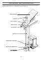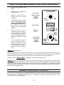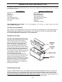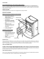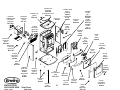
1
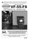
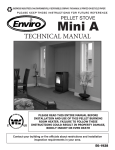
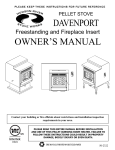
PELLET STOVE
EF-V EVOLUTION
OWNERS TECHNICAL MANUAL
SHERWOOD INDUSTRIES LTD.
6782 OLDFIELD RD
VICTORIA, BRITISH COLUMBIA V8M-2A3
ENVIROFIRE INSTALLATION MANUAL
TABLE OF CONTENTS
1) INTRODUCTION
PAGE
Pellet Quality ........................................................................ 3
Important Safety Data........................................................... 4
Warnings and Recommendations......................................... 5
Automatic Safety Features ................................................... 5
Deciding Where To Locating Your Pellet Appliance ............. 6
Fireplace Dimensions ........................................................... 6
Removing Your New Stove From It’s Pallet.......................... 7
Pedestal Installation ............................................................. 7
4) INSTALLATION
Vent Termination Requirements ........................................... 8
Clearances to Combustibles................................................. 9
Mobile Home Installation .................................................... 10
Outside Fresh Air Connections........................................... 10
Horizontal Exhaust through the Wall ............................. 11-12
Inside Vertical Pipe Installation........................................... 13
Hearth Mount Installation.................................................... 14
Exterior Mounted Exhaust Blower ................................. 15-18
2) OPERATION
How to Start Your Pellet Appliance..................................... 19
Turning Your Pellet Appliance Off ...................................... 19
Slider/Damper..................................................................... 20
3) SPECIFICATIONS / MAINTENANCE
Areas for Routine Maintenance ..................................... 21-22
Electrical Component Functions .................................... 23-25
5) SERVICE
Troubleshooting............................................................. 26-29
Wiring Diagram................................................................... 30
Parts List ............................................................................ 31
Exploded views.............................................................. 32-33
Warranty ............................................................................. 34
2
PELLET QUALITY IS IMPORTANT, PLEASE READ THE
FOLLOWING PAGE
Your pellet stove has been designed to burn wood pellets only. Since there are many manufacturers of
wood pellets it is important to select pellets that are free of dirt or any impurities. The Pellet Fuel
Industries (P.F.I.) has established standards for wood pellet manufactures. We recommend the use of
pellets that meet or exceed these standards. Ask your dealer for a recommended pellet type.
THE PERFORMANCE OF YOUR PELLET STOVE IS GREATLY AFFECTED BY THE TYPE AND
QUALITY OF WOOD PELLETS BEING BURNED. AS THE HEAT OUTPUT OF VARIOUS QUALITY
WOOD PELLETS DIFFER, SO WILL THE PERFORMANCE AND HEAT OUTPUT OF THE PELLET
STOVE.
Since Sherwood Industries Ltd. has no control over the quality of pellets that you use, we assume no
liability caused by the quality of wood pellets used.
P.F.I. PELLET STANDARDS:
Fines .....................................1% maximum through a 1/8” screen
Bulk Density ..........................40 lbs. per cubic foot minimum
Size .......................................1/4” to 3/8” diameter 1 – 1.5” long maximum
Ash Content ..........................1% maximum
Moisture Content...................8% maximum
Heat Content .........................approximately 8200 Btu per lb. minimum
Check the burn-pot liner periodically to ensure that the holes are not blocked with clinkers, (clinkers are
silica in the fuel that will form a hard mass during the burning process). If they are blocked, remove the
liner (when the unit is cold) and clean the clinkers out. The liner should be cleaned or scraped once
every 2-3 days depending on wood pellet quality. Clean the holes in the lines with a small pointed
object.
Store pellets at least 36” (1 m) away from the pellet stove.
3
IMPORTANT SAFETY DATA
To prevent the possibility of a fire, ensure that the appliance is properly installed by adhering to the
installation instructions. An ENVIROFIRE dealer will be happy to assist you in obtaining information
with regards to your local building codes and installation restrictions.
The stove’s exhaust system works with negative combustion chamber pressure and a slightly positive
chimney pressure, it is very important to ensure that the exhaust system be sealed and airtight.
This unit is designed to burn pelletized wood fuel only. Do not use any other type of fuel, this will void
any warranties stated in this manual.
THE USE OF CORDWOOD IS PROHIBITED BY LAW.
Do not burn with insufficient combustion air. A periodic check is recommended to ensure proper
combustion air is admitted to the combustion chamber. Setting the proper combustion air is achieved
by adjusting the slide damper located on the left side of the stove.
It is advisable to clean the exhaust vent bi-annually or every two tons of pellets.
The grounded electrical cord should be connected to a standard 115 volts, 60-hertz electrical outlet. Be
careful that the electrical cord is not trapped under the appliance and that it is clear of any hot surfaces
or sharp edges. This unit’s maximum power requirement is 470 watts (3.91amps) for the EF-V
EVOLUTION.
Minor soot or creosote may accumulate when the stove is operated under incorrect conditions such as
an extremely rich burn (black tipped, lazy orange flames).
When installing the stove in a mobile home, it must be electrically grounded to the steel chassis of the
home and bolted to the floor. Make sure that the structural integrity of the home is maintained.
Be sure to maintain the structural integrity of home when passing a vent through walls, ceilings, or
roofs.
The ash pan must be locked securely for proper and safe operation of the pellet stove.
If you have any questions with regards to your stove or the above-mentioned information, please feel
free to contact your local dealer for further clarification and comments.
Since Sherwood Industries Ltd. has no control over the installation of your stove, we grant no warranty
implied or stated for the installation or maintenance of your stove, therefore, Sherwood Industries Ltd.
assumes no responsibility for any consequential damage.
SAVE THIS INSTRUCTION MANUAL FOR FUTURE REFERENCE
4
WARNINGS AND RECOMMENDATIONS
A.
Do not abuse the glass by striking or slamming the door shut.
B.
Do not attempt to operate the stove with broken glass.
C.
Do not attempt to open the door and clean the glass while the unit is in operation. To clean the
glass, use a soft cotton cloth and mild window cleaner, gas or wood stove glass cleaner or take
a damp paper towel and dip into the fly ash, this is a very mild abrasive and will not damage the
glass.
D.
Do not use abrasive cleaners to clean the surface or any part of the stove.
E.
It is recommended that the unit be secured into its position in order to avoid any displacement.
F.
Never use gasoline, gasoline-type lantern fuel, kerosene, or similar liquids to start the fire. Keep
all such liquids well away from the pellet stove while it is in use.
G.
Disposed ashes should be placed in a metal container with a tight fitting lid. The closed
container of ashes should be on a non-combustible floor on the ground, well away from all
combustible materials pending final disposal. The ashes should be retained in the closed
container until all cinders have thoroughly cooled before disposing of them.
H.
Make sure the ash pan is closed tightly during the operation of the stove.
I.
KEEP ASH PAN FREE OF RAW FUEL. DO NOT PLACE UNBURNED OR NEW PELLET
FUEL IN ASH PAN. A fire in the ash pan could be the result.
J.
Fresh air intake is strongly recommended. Failure to install Intake air may result in the unit
smoking during power failures as well as improper combustion.
NOTE: Fresh air is mandatory on all units installed in “Mobile Homes” as well as “Air
Tight” homes.
AUTOMATIC SAFETY FEATURES OF YOUR PELLET STOVE
A.
The stove will shut off when the fire goes out and the exhaust temperature drops below 120°F
(49°C).
B.
The stove has a high temperature safety switch. If the temperature on the hopper reaches
200°F (93°C) the auger will automatically stop, and the stove will shut down when the exhaust
temperature cools. If this happens call your local dealer to reset the 200°F (93°C) high limit
switch. ALSO FIND THE REASONS WHY THE UNIT OVERHEATED.
C.
If the power goes out, the unit will stop running. When the power comes back on, the stove will
not restart unless the exhaust temperature is still above 120°F (49 °C).
5
DECIDING WHERE TO LOCATE YOUR PELLET APPLIANCE
1.
Check clearances to combustibles.
2.
Do not obtain combustion air from an attic, garage or any unventilated space. Combustion air may be
obtained from a ventilated crawlspace.
3.
Do not install the stove in a bedroom.
4.
You can vent the stove through an exterior wall behind the unit or connect it to an existing masonry or
metal chimney (must be lined if the chimney is over 6” in diameter, or over 28 sq. inches cross sectional
area). An interior vent can be used with approved pipe passing through the ceiling and roof.
5.
Locate the stove in a large and open room that is centrally located in the house. This will optimize heat
circulation.
6.
The power cord is 8 feet (2.43 m) long and may require a grounded extension cord to reach the nearest
electrical outlet.
FIREPLACE DIMENSIONS
FRONT VIEW
SIDE VIEW
UNIT DIMENSIONS
HEIGHT: 33.056 (83.96 CM)
WIDTH: 22.225 (56.45 CM)
DEPTH: 21.239 (53.94 CM)
HEARTH PAD:
WIDTH: 24.360 (61.87 CM)
DEPTH: 27.864 (70.77 CM)
TOP VIEW
6
REMOVING YOUR NEW STOVE FROM THE PALLET
To remove your new stove from its pallet, open the left and right side panels. There are two wood screws that are
holding the bottom of the stove to the pallet. Remove the screws. Close the side panels.
To remove the right and left hand cabinet sides there
are three T-20 Torx screws on the back of the panel,
loosen these screws only.
Remove the one screw located on the front of the
cabinet side located behind the top louvers.
Remove the two wood screws (one on either side of
the unit) to remove the unit from the pallet.
HEARTH PAD PEDESTAL INSTALLATION
Carefully place the back of the pellet appliance on the pallet and install the hearth pad. Align the holes in the
hearth pad and the unit and install the four screws provided.
Place the unit on its back and install the hearth pad using the four screws provided
This unit can be installed on a
combustible floor due to the built in
pedestal hearth pad, for example
linoleum, hardwood flooring. If this unit
is to install onto a carpeted surface a
hearth pad must be used for stability.
This unit is supplied with 4 leveling legs
for uneven surfaces. Adjust these
leveling legs until unit is level.
LEVELING LEGS
X4
7
VENT TERMINATION REQUIREMENTS
1. Do not terminate the vent in any enclosed or semi-enclosed areas such as a carport, garage, attic,
crawlspace, narrow walkway, closely fenced area, under a sundeck or porch, or any location that can build up
a concentration of fumes such as stairwells, covered breezeway, etc.
2. Vent surfaces can become hot enough to cause burns if touched by children. Non-combustible shielding or
guards may be required.
3. Termination must exhaust above the inlet elevation. It is recommended that at least five feet of vertical pipe
be installed outside when the appliance is vented directly through a wall to create some natural draft to
prevent the possibility of smoke or odor during appliance shut down or power failure. To keep exhaust from
causing a nuisance or hazard from exposing people or shrubs to high temperatures. In any case, the safest
and preferred venting method is to extend the vent through the roof vertically.
4. Vent terminal cannot be:
less than 4 feet (1.2 m) below
less than 4 feet (1.2 m) horizontally from, and
less than 1 foot (305 mm) above
Doors, window openings, or gravity/ventilation air inlet into building:
5. Distance from bottom termination and grade –12” (305 mm) minimum.(including exterior exhaust blower) This
is conditional upon the plants and nature of grade surface. The exhaust gases are hot enough to ignite grass,
plants and shrubs located in the vicinity of termination. The grade surface must not be lawn. Distance from
bottom of termination and public walkways is 7 feet (2.1 m) minimum.
6. Distance to combustible materials is 2 feet (610 mm). This includes adjacent buildings, fences, protruding
parts of the structure, roof overhang, plants, shrubs, etc.
7. If the unit is incorrectly vented or the air to fuel mixture is out of balance, a slight discoloration of the exterior
of the house might occur. Since these factors are beyond Sherwood Industries LTD’s. control, we grant no
guarantee against such incidents.
IT IS RECOMMENDED THAT AN AUTHORIZED DEALER/INSTALLER INSTALL YOUR PELLET STOVE
G
W
A
B
H
C
F
F
A
E
NOTE: Measure clearance to the nearest edge of the exhaust hood
A- MINIMUM 4 feet (1.2m) below or beside any door or window that opens.
B- MINIMUM 1 foot (305 mm) above any door or window that opens.
C- MINIMUM 2 feet (610 mm) from any adjacent buildings.
D- MINIMUM 7 feet (2.1 m) above grade when adjacent to public walkways.
(NOTE) Vent may not terminate in a covered walkway or breezeway.
E- MINIMUM 2 feet (610 mm) above plants, grass or other combustible
materials.
F- MINIMUM 3 feet (915 mm) from any forced air intake of other appliances.
G- MINIMUM 2 feet (610 mm) below any eave or roof overhangs.
H- MINIMUM 1 foot (305 mm) clearance to a combustible wall.
W- MINIMUM 2 feet (610 mm) above the roof.
8
D
CLEARANCES TO COMBUSTIBLES
This unit can be installed on a combustible floor due to the built in pedestal hearth pad, for example linoleum,
hardwood flooring. If this unit is to install onto a carpeted surface a hearth pad must be used for stability.
Back Wall
Adjacent Wall
Side Wall
SIDE WALL TO UNIT
BACK WALL TO UNIT
ADJACENT WALL
6 INCHES (900 MM)
2 INCHES ( 50 MM)
2 INCHES (50 MM)
ALCOVE CLEARANCES
This unit may be installed in an Alcove. Maintain these clearances to combustibles.
ALCOVE WIDTH
ALCOVE HEIGHT
ALCOVE DEPTH
36 INCHES (900 MM)
48 INCHES (1200 MM)
48 INCHES (1200 MM)
INSTALL VENT AT CLEARANCES SPECIFIED
BY THE VENTING MANUFACTURE.
9
EXHAUST AND FRESH AIR INTAKE DIMENSIONS
EXTERNAL MOUNTED EXHAUST BLOWER.
(A)
Base to center of flue
Side to center of flue
8.36 inches (21.34 CM)
8.16 inches (20.72 CM)
INTERIOR MOUNTED EXHAUST BLOWER.
(B)
Base to center of flue
Side to center of flue
10.71 inches (27.20 CM)
10.62 inches (26.97 CM)
(B)
FRESH AIR INTAKE.
(A)
Base to center of intake 8.47 inches (21.51 CM)
Side to center of intake 7.97 inches (20.54 CM)
MOBILE HOME INSTALLATION
-
Secure the heater to the floor using the two holes in the pedestal. Do not disturb the structural integrity of
the home.
-
Ensure the unit is electrically grounded to the chassis of your home (permanently).
-
Do not install in a room people sleep in.
-
Outside fresh air is mandatory.
OUTSIDE FRESH AIR CONNECTIONS
Outside fresh air is mandatory when installing this unit in airtight homes and mobile homes. When
connecting to an outside fresh air source, do not use plastic, combustible pipe. Only 2” ID (inside diameter) steel,
aluminum or copper pipe should be used. It is recommended, when you are installing a fresh air system, to keep
the number of bends in the pipe to a minimum.
10
INSTALLATION
HORIZONTAL THROUGH WALL INSTALLATION
The ENVIROFIRE EF V EVOLUTION can be vented through the wall using two different methods.
STRAIGHT THROUGH THE WALL.
1.
Choose a location for your stove that meets the requirements stated in this manual and allows installation
with the least amount of interference to house framing, plumbing, wiring, etc.
2.
Place the appliance 15” (37.5 cm) away from the wall. If the stove is to be set on a hearth pad, set the
unit on it.
3.
Locate the center of the exhaust pipe on the stove. Extend that line to the wall. Once you have located
the center point on the wall, use a hole saw to cut a 10” (254 mm) diameter hole for a 3” (76 mm) vent
pipe or an 11” (279 mm) hole for a 4” (101 mm) vent pipe.
4.
Install the wall thimble as per the instructions written on the thimble.
5.
Install a length of 3” (76 mm) or 4” (101 mm) vent pipe into the wall thimble. The pipe should install easily
into the thimble.
6.
Install the fresh air intake.
7.
Connect the exhaust vent pipe to the exhaust pipe on the stove.
temperature silicone
8.
Push the stove straight back, leaving a minimum of 2” (5 cm) clearance from the back of the stove to the
wall. Seal the vent pipe to the thimble with high temperature silicone.
9.
The pipe must extend at least 12”(30 cm) away from the building. If necessary, bring another length of
pipe (PL type) to the outside of the home to connect to the first section. Do not forget to place high
temperature silicone around the pipe that passes through the thimble.
10.
Install a vertical pipe, or if all requirements for direct venting are met, install vent termination. The
stainless steel cap termination manufactured by the vent manufacturer is recommended. However, when
the vent terminates several feet above ground level and there are no trees, plants, etc. within several feet,
a 45-degree elbow with rodent screen can be used as a termination. The elbow must be turned down to
prevent rain from entering.
Seal all connections with high
NOTE:
Some horizontal through wall installations may require a “T” and a 3 to 5 foot of vertical pipe outside the building
to help natural draft in the unit.
This may be required if a proper burn cannot be maintained, after the stove has been tested and the airflow set.
This is due to the backpressure in the exhaust caused by air-flow around the structure.
11
STRAIGHT THROUGH WALL INSTALLATION
WALL FRAMING
INTERIOR WALL SURFACE
TERMINATION CAP
WALL THIMBLE
VENT PIPE
EF-V EVOLUTION
THROUGH WALL WITH VERTICAL RISE (recommended)
WALL FRAMING
TERMINATION CAP
INTERIOR WALL
SURFACE
VERTICAL SECTION OF
VENT PIPE
WALL THIMBLE
EF-V EVOLUTION
12
VERTICAL INSTALLATION
1.
Choose a stove location that is ideal. See the section Deciding Where to Locate Your Pellet Appliance.
2.
Place the unit on the hearth pad (if installed on a carpeted surface.) and space the unit in a manner so
when the pellet vent is installed vertically, it will be 3” (76 mm) away from a combustible wall.
3.
Locate the center of the fresh air intake pipe on the unit. Match that center with the same point on the
wall and cut a hole about 2 1/8 (53.9 mm) in diameter.
4.
Install the fresh air intake pipe.
5.
Install the tee with clean out.
6.
Install the pellet vent upward from there. When you reach the ceiling make sure that the vent goes
through the ceiling fire stop. Maintain a 3” (76 mm) distance to combustibles and keep attic insulation
away from the pipe.
7.
Finally, extend the pellet vent to go through the roof flashing.
8.
Ensure that the rain cap is approximately 36” (900 mm) above the roof.
9.
The same methods apply for vertical installation outside. Install wall thimble and pipe supports.
RAIN CAP. ENSURE CAP IS A LEAST
3 FEET ABOVE THE ROOF AT THE
LOWEST POINT.
3 FEET
(92 CM)
ROOF FLASHING
ROOF RAFTER
FIRE STOP with SUPPORT COLLAR
CEILING JOIST
VERTICAL VENT PIPE
CLEAN OUT TEE with PIPE ADAPTER
EF V EVOLUTION
NOTE:
ALL VENT SECTIONS MUST
MAINTAIN 3 “ INCHES (7.62 CM)
CLEARANCES TO COMBUSTIBLES.
13
HEARTH MOUNT INSTALLATION
1.
Lock fireplace damper in the open position.
2.
Install positive flue connector at the fireplace dampers.
3.
Connect a Tee or a 90° degree elbow to the exhaust pipe.
4.
Install flexible stainless steel liner or listed pellet vent to the top of the chimney.
RAIN CAP.
SEAL PLATE.
EXISTING MASONRY FLUE.
VENT PIPE. ( single wall stainless flex pipe or
solid PL vent.)
FLEXIBLE VENT CONNECTOR.
(Use this 5 foot section of pipe to vent past
fireplace damper or smoke shelf.)
FIREPLACE DAMPER LOCATION
CLEAN OUT TEE.
EXISTING FIREPLACE.
EF V EVOLUTION.
14
EXTERIOR MOUNTED EXHAUST BLOWER
The EF V EVOLUTION can be equipped with an externally mounted exhaust blower.
This optional kit would include all components necessary to install the exhaust blower on any vertical wall surface.
Choose a location for your stove that meets the requirements stated in this manual and allows installation with the
least amount of interference to house framing, plumbing, wiring, etc.
Included in the exterior mounted exhaust blower kit are:
1---Exhaust blower housing.
1---60° degree pipe to stove adapter.
1. Remove the left hand cabinet side by removing
(1) one screw between the top louvers. Loosen the three screws on the back of the cabinet side and
remove panel.
2. Loosen the four screws that hold the top back grill in place. Lift the back grill off the screws and remove
NOTE: Remove the knock out to the lower right of the oval hole. This will be the new chimney location.
3. Remove the two small sections of exhaust
pipe from the exhaust blower.
4. Discard the middle section of exhaust pipe
5. Re install the exhaust pipe marked # 1 to
exhaust blower and remove the exhaust
blower from the unit by undoing the (5) five
bolts the secure the blower to the housing.
6. Install the 60° deg pipe to stove adapter to
the exhaust channel in place of the exhaust
blower.
60 ° DEGREE PIPE TO STOVE ADAPTER
INSTALLED TO EXHAUST CHANNEL.
15
7. Remove the front and bottom sections of the EXTERIOR EXHAUST BLOWER HOUSING and install the
exhaust blower ensuring that the gasket
material is not damaged and is properly
positioned.
8. Re install the top and bottom sections of
the exhaust blower housing and place a
bead of high temperature silicone around
the exhaust pipe were it exits the exhaust
blower housing to create a watertight
seal.
HIGH
TEMPERATURE
SILICONE
Replace the back grill of the stove and ensure the four screws are tightened.
Follow the procedures for through wall installations. Place the unit in the desired location. Cut hole in the wall at
the desired location.
Apply normal venting practices when installing the vent pipe. Start by installing a pipe adapter, then a short
section of pipe or an adjustable section through a wall thimble to maintain clearances to combustibles.
COMPLETED
EXHAUST BLOWER
16
TYPICAL THROUGH WALL OUTSIDE TERMINATION INSTALLATION.
EF V EVOLUTION
90° DEGREE ELBOW
45° DEGREE ELBOW WITH
RODENT SCREEN OR
STAINLESS STEEL
TERMINATION HOOD
2 FOOT RISER
PIPE ADAPTER
ELECTRICAL CABLE
EXTERIOR BLOWER AND
HOUSING
SIDE VIEW
NOTE:
WALL STRAP
Ensure that all vent
connections be installed
by placing a small bead
of high temperature
silicone at each chimney
connection.
Also ensure that all
vertical vent sections are
proper supported and
the all clearances to
combustibles are
maintained in
accordance with the vent
manufacturer’s
specifications.
TO SUPPLY POWER TO THE EXHAUST BLOWER:
Install an amour coated electrical cable from the exhaust
blower housing, through the wall thimble and attach to the pre
drilled hole in the left hand rear hopper pillar, and hook up to
wires from the wiring harness for exhaust blower
All electrical connections must be in accordance to local code
requirements.
17
THROUGH WALL VERTICAL INSTALLATION
Follow the previous pages for through wall installations. Ensure that vent pipe is properly secured to wall using
wall straps. Maintain clearances to combustibles on vent pipe as well as unit.
ROOF SHEATHING.
RAIN CAP.
ROOF FLASHING.
ROOF RAFTERS.
CEILING JOISTS.
VENT PIPE.
EXTERIOR WALL SHEATHING.
OUTSIDE VENT TERMINATION.
EF V EVOLUTION.
18
HOW TO START AND OPERATE YOUR PELLET APPLIANCE
1.
Check and fill hopper with
pellets.
2.
Make sure unit is plugged into
a working outlet.
3.
Switch the power “ON” by
pushing the start up switch
once only.
4.
Turn knob “B” to the 12 o’clock
position. (Lower grade pellets
may need a higher setting on
the feed rate). NOTE: unit will
take longer to light if the
hopper has been completely
emptied.
5.
6.
Wait
until
the
fire
is
established, then turn knob “B”
to the desired heat output.
(The stove may not be able to
burn in the BLUE ZONE if poor
quality wood pellets are being
used.)
If the stove should shut off
after 15 minutes and there is
still a fire in the firebox – press
the start up switch once more.
If the fire went out, return to
step number 2 and re-light the
stove.
Convection
Blower Speed
Control
KNOB A
Auger Light
Start-up
Switch
Dial-A-Fire
Heat Output
Knob
KNOB B
KNOB “A”: Fan Controller.
By adjusting the knob you will vary the rate of airflow into the room by varying the speed of the convection blower.
When you first start the stove it should be placed in the “OFF” position in order to heat the unit as quickly as
possible. Once the room has come up to temperature the control may be set to a comfortable level.
The flashing green “Auger Light” corresponds to the timing of the auger turning.
KNOB “B”: Dial a Fire Heat Output Knob. This knob controls the amount of heat output. The dial has a scale
with the blue zone representing the coolest setting of the stove, and the red zone representing the hottest
setting. The scale on knob “B” represents a range, not exact at times or fuel quantities. Wood pellets of differing
quality may effect the performance of the stove. If the stove has trouble operating at either end of its range, turn
the heat output knob back slightly.
TURNING YOUR PELLET STOVE OFF
To turn your stove off, simply turn the HEAT OUTPUT knob (knob “B”) counter-clockwise until the knob clicks to
the “OFF” position. This will stop the feed of pellets. The blowers will continue to run and cool the stove. When
cool enough, the stove will shut down.
19
SLIDER/DAMPER INSTALLATION INSTRUCTIONS
This is used to regulate the airflow through the pellet stove.
A Qualified Service Technician or Installer should set the Slider Damper.
The Slider Damper has been pre set at the factory. However, during installation this slider damper might require
further adjustment depending on type of installation or fuel quality.
The slider damper is located behind the left side panel. To open the left side panel, undo the one screw located in
the upper front corner of the cabinet side between the louvers, also loosen three screws down the back of the
side panel.
AIR INTAKE BOX
EXHAUST CHANNEL
SLIDER DAMPER
EXHAUST BLOWER
The combustion exhaust blower is a variable speed blower controlled by the heat output knob,(Dial a Fire). This
blower will decrease the vacuum pressure inside the stove and as the heat output knob is turned up. The vacuum
pressure inside the firebox will increase as the combustion exhaust blower increases in speed.
If the fire should happen to go out and the Dial A Fire has been set on the lowest setting, the Slider Damper
should be pushed in slightly decreasing the air in the firebox.
If after long periods of burning the fire builds up and over flows the burn pot or there is a build up of clinkers This
would be a sign that the pellet quality is poor and the slider damper must be pulled out to compensate.
Pulling the slider damper out gives the fire more air.
The easiest way to make sure that an efficient flame is achieved is to see the characteristics of the fire.
• A tall and lazy flame with dark orange tips requires more air – Open slider / damper up.
• A short and brisk flame, like a blowtorch, has too much air – Close slider / damper down.
• If the flame is in the middle of these two characteristics with a bright yellow/orange, active flame then the air is
set for proper operation.
SPECIAL NOTES:
Pellet quality is a major factor in how the Pellet stove will operate. If the Pellets have a high moisture content or
ash content the fire will be less efficient and has a higher possibility of the fire building up and creating clinkers.
(hard ash build-up)
20
AREAS FOR ROUTINE INSPECTION
The following should be inspected periodically to ensure that the appliance is operating at its optimum and giving
you excellent heat value:
2 3 DAYS/WEEKLY
Burn Pot and Liner
Ash Pan
Inside Firebox
Door Glass
Heat exchanger tubes
Ash pan and Door gaskets
Door Latch
SEASON or 2 TONS OF FUEL
Exhaust Vent
Fresh air Intake Tube
Blower Mechanisms
Heat exchanger tubes
Latch Mechanism of ash pan
Behind firebox liners
All Hinges
Post Season Clean-up
TOOLS REQUIRED TO CLEAN UNIT:..Torx T-20 Screwdriver, 5/16” wrench or socket, Brush, Soft Cloth,
Vacuum with fine filter bag
ASH PAN AND DOOR GASKETS
After excessive use the gasketing may come loose. To repair this, glue the gasketing on using high-temperature
fiberglass gasket glue available from your local dealer. This is important to maintain an airtight assembly. DO
NOT PLACE UNBURNED OR RAW PELLET FUEL IN ASH PAN.
BURNER POT AND LINER
This is the ‘pot’ where the pellets are burned.
Every two to three days (when the unit is cold),
remove the burn-pot liner from the stove.
Using a metal scrapper remove material that
has accumulated or is clogging the liner’s
holes. Then dispose of the scrapped ashes
from the liner and from inside the burn-pot.
Place the burn-pot back into the stove, making
sure that the pipes are properly inserted into
the burn pot. Place the liner back into the burnpot, making sure that the ignitor hole in the liner
is aligned with the ignitor tube. Pushing the
liner up against the igniter tube.
To remove the burn pot and burn pot liner.
Open the door using the door handle provided
located on the left-hand side of the stove,
swing the door open. Lift the liner from the burn
pot, lift the burn pot from the firebox by gently
lifting the front of the burn pot up first then
sliding the assembly from the air intake tube
and the igniter cartridge.
BURN POT
LINER
FRESH AIR
TUBE
IGNITER TUBE
BURN POT
FREESTANDING ASH PAN:
This part is located under the burner, in the pedestal and has a latching mechanism to secure it. To remove the
ash pan, open the cover from the right hand side, unlock the latch on the pedestal cover and then pull the pan
out. Dump the ashes into a metal container stored away from combustibles. Monitor the ash level every week.
Remember that different pellet fuels will have different ash contents. Ash content is a good indication of fuel
efficiency and quality. Refer to “Warnings and Recommendations” for disposal of ashes.
21
DOOR GLASS
(It is recommended that your dealer replace the glass if broken.)
The door glass is made of high temperature PYRO CERAMIC. The center panel is 14” x 14” inches (35.5cm x
35.5 cm). To replace the glass, unscrew and remove the four glass retainers. Remove the glass and any broken
pieces. High temperature fiberglass tape should be used around the glass. Replace the glass by screw the glass
retainers back to the frame.
FRESH AIR INTAKE
Inspect periodically to be sure that it is not clogged with any foreign materials.
EXHAUST PASSAGES
Removal of the firebox backing for bi-annual cleaning
•
•
•
•
•
•
Open the door by lifting the
handle, Remove the burn pot
and burn pot liner.
Lubricate all screws with
penetrating oil.
Remove the four screws that
hold the Brick liner and side
panels in place. Remove Brick
liner
With the tip of a flat
screwdriver, gently lift up the
side panels and remove the
side panels.
Pull the center panel out.
Vacuum thoroughly.
CENTER PANEL
SIDE PANELS X 2
Installation of firebox backing:
•
•
•
•
Insert center panel.
Place the two side panels back
into the firebox and Brick liner,
reinstall the two screws on
each side.
Replace the glass door and
secure.
Clean thoroughly.
BRICK LINER
EXHAUST VENT
This vent should be cleaned every year or after two tons of pellets. We recommend contacting your dealer for
professional cleaning. To clean the vent pipe, tap lightly on the pipe to dislodge any loose ash. Open the bottom
of the ”T” to dump the ash, then vacuum as much of the ash out of the vent pipe as possible.
HEAT EXCHANGER TUBES
A handle is located under the unit top, in the center of the stove just above the door. This handle is to be pulled up
and down a few times (ONLY WHEN THE UNIT IS COLD) in order to clean away any fly ash that may have
collected on the heat exchanger tubes. As different types of pellets produce different amounts of ash, cleaning of
the tubes should be done on a regular basis to enable the unit to run efficiently.
POST SEASON CLEAN-UP
Once you are finished using the pellet appliance for the season, unplug the stove for added electrical protection.
It is very important that the stove be cleaned and serviced as stated above.
22
ELECTRICAL COMPONENT AND FUNCTIONS
Some parts have been removed for clarity.
12
9
11
10
7
6
17
8
13
5
4
15
3
2
16
1
23
14
The following is a list of electrical components and their functions on the ENVIROFIRE EF-V EVOLUTION
pellet stove.
1
POWER CORD OUTLET.
Main power supply to the unit supplied at this location.
2
CONVECTION BLOWER.
This blower fan, (mounted in the center bottom of the unit) draws room air from the back of the stove and passes
the air through the heat exchanger tubes and back into the room. The sealed system keeps the room air separate
from the combustion air. The convection blower’s fan controller controls the fan’s speed.
3
START-UP TIMER.
This 15 minute one shot timer, by-passes the 120° F (49°C) temperature sensor allowing the unit to operate when
cold. The timing cycle is initiated by pressing the start-up switch. The 15 minute timer is located right under the
timing control module on the right side pillar. The unit is also responsible for initiating the ignition cycle.
4
TIMING CONTROL MODULE.
The timing control module is mounted in the middle, on the right rear pillar of the unit. This module controls the
switching power of the auger motor. The module’s switching duty cycle is controlled by the Dial-A-Fire.
5
AUGER MOTOR.
This 1RPM motor is responsible for turning the auger, which in turn transports pellets to be dropped into the burn
pot liner. The auger motor’s control is handled by the timing control module and Dial-A-Fire.
6
COMBUSTION/EXHAUST PHASE CONTROLLER (Blower speed control module).
The phase controller supplies an adjustable voltage to the combustion blower. The voltage controls the blower’s
speed. The module is controlled by the potentiometer in the Dial-A-Fire. As the feed rate is increased, the
blower’s speed is increased proportionally.
7
IGNITER.
This is a heating element used to ignite the fuel. When the pellet stove is started, the igniter is energized. Air
passes through the igniter tube over the igniter. The air becomes super heated, drying the pellet fuel and then
igniting the pellets through convection. The igniter is located in the center of the firebox next the air inlet tube.
8
DIAL-A-FIRE (Heat output knob).
This unit is responsible for controlling the timing of the auger motor. When turned clockwise it will cause the OFF
time between auger pulses to shorten. Resulting in more heat output and pellet consumption. Turn the knob
counter-clockwise and the reverse will happen. When this knob is turned fully counter-clockwise past the click, the
auger motor will be turned off. This component also controls the exhaust blower speed via the PHASE
CONTROLLER.
9
START-UP SWITCH.
When the momentary contact switch is pressed it will initiate the 15 minute Start-Up Timer including the igniter.
10
AUGER PULSE LIGHT.
This light will flash in conjunction with the pulses to the auger.
24
11
CONVECTION FAN CONTROLLER.
This controller is responsible for varying the speed of the convection blower.
12
200° F (93° C) MANUAL RESET TEMPERATURE SENSOR.
This sensor (located on the right side hopper) has a red button located in the center of the sensor. This sensor will
turn the auger OFF if the hopper reaches 200° F (93° C). Depress the button to reset if the sensor has been
activated.
13
120°F (49°C) N/O, TEMPERATURE SENSOR (SHUT-DOWN SENSOR).
This sensor (mounted on the exhaust blower housing) has two functions:
Should the fire go out, this sensor will shut the stove off when the exhaust temperature drops below 120°F (49°C).
When the auger is turned off via the dial-a-fire, the exhaust temperature will drop, when it goes below 120°F
(49°C) the sensor will turn the stove off.
14
120°F (49°C) N/C, TEMPERATURE SENSOR (IGNITER SHUT DOWN SENSOR).
This sensor (mounted on the exhaust channel) will turn the igniter off when the firebox temperature reaches
120°F (49°C).
15
EXHAUST/COMBUSTION BLOWER.
This variable speed fan (mounted on the left side of the stove) is responsible for drawing the outside fresh air into
the combustion chamber for burning. The hot air then continues to be drawn over the heat exchanger tubes and
into the exhaust channel. It is then pushed out through the exhaust system. A motor speed controller tied in with
the Dial-A-Fire controls the speed of the blower.
16
VACUUM SWITCH.
This safety device (mounted on the left side back pillar) detects vacuum in the exhaust system. If the exhaust
blower fails or the vent pipe becomes plugged, this switch will sense that there is no airflow and will stop the
auger from continuing to feed pellets.
17
THERMOSTAT INTERFACE.
This control module is responsible for switching between a factory setting (for auger timing and exhaust voltage)
and the control panel settings when the wall thermostat calls for heat.
Exhaust trim:
Used to increase or decrease voltage to exhaust blower.
Auger trim:
Used to increase the fuel feed rate for poor or lesser quality fuels.
Thermostat hook up: Install a 12 or 24, volt thermostat in this location.
EXHAUST
TRIM
AUGER
TRIM
THERMOSTAT
HOOK UP
POWER
IN
25
TROUBLESHOOTING:
DO NOT:
-
Hold the start-up switch down, this is a momentary contact switch and can be damaged
if held down too long.
-
Service the stove with wet hands. The stove is an electrical appliance, which may pose
a shock hazard if handled improperly. Only qualified technicians should deal with
possible internal electrical failures.
-
Remove any screws in the firebox without first lubricating them with penetrating oil.
What to do if:
1. The stove will not start.
2. The stove will not operate when hot.
3. The exhaust blower will not function normally.
4. The convection blower will not function normally.
5. Igniter : The pellets will not light.
6. The auger motor does not function normally.
7. The Dial-A-Fire has no effect on the fire.
8. The stove will not shut off.
9. The stove keeps going out.
10. Thermostat interface does not work correctly.
*NOTE: All troubleshooting procedures should be carried out by qualified technicians or installers.
1.
The stove will not start
-
Make sure the stove is plugged in and the wall outlet is supplying power.
Push the Start-up switch, if the stove fails to start, unplug the unit and open the hinged
side panels (held tight with one screw at the top, front).
With the stove unplugged, examine all connections. Make sure they are firmly
connected and that there are no exposed wires touching the stove (except the chassis
ground wire).
Check the continuity and placement of connections against the diagram in the back of
this manual.
Ensure that the connections to the (15) minute start-up timer are correct.
Attempt to bypass the switch by inserting a jumper wire between the red and white wires
that attach to the switch. Plug the stove back in. If the stove starts, replace the switch.
If this fails, replace the (15) minute start-up timer.
26
The stove will not operate when hot
-
2.
The exhaust motor will not function normally
-
3.
Open the left side panel, check all connections against the wiring diagram.
Thoroughly check for broken wires or connections.
If all the connections are verified and the exhaust blower does not function at all, tap
lightly on the exhaust blower’s motor end cap, this may loosen a tight motor.
Apply 115 V directly to the exhaust blower. If the motor does not run, replace the
blower.
If the motor runs, check the exhaust potentiometer in the Dial A Fire. Remove the grey
wires from the exhaust motor speed controller and measure the resistance (10 ohms. to
400k ohms). If this range is not present or it is an open circuit Replace the speed
controller.
Check all wires for continuity
Replace the exhaust motor phase control (speed control module).
The convection blower will not function normally
-
5.
Unplug the stove, open the left side panel. Jump the two brown leads that are attached
to the 120°F (49°C) Exhaust temperature sensor. If the stove operates replace the
120°F (49°C) sensor.
Check all the connections between the controller, switch, and the convection blower
against the wiring diagram.
If the convection motor will not run, apply 115 V to the motor directly. If the motor runs,
replace the fan controller. If the motor does not run, the convection blower has failed.
Replace the blower.
If the convection blower runs on high at all times (no control with the fan controller),
check the connections from the 160°F (71°C) sensor (located on the upper left side of
the firewall) and convection fan controller to the blower. Disconnect one of the wires
from the sensor, if control of the convection blower returns to the fan controller, replace
the sensor.
If the motor is still on high, re-connect the sensor and replace the convection fan
controller.
Igniter- the pellets will not light
Everything else in the stove operates but the igniter will not light the pellets
Make sure the burnpot liner is up tight and square to the ignitor tube.
Check to see if the exhaust blower is operating.
Check all the electrical connections on the 120°F (49°C) temperature sensor located on
the exhaust channel.
Check the connections at the igniter socket.
Place a jumper wire between the two leads on the 120°F (49°C) temperature sensor. If
the igniter works. Replace the sensor.
If the igniter does not work. Replace the igniter
NOTE: The igniter should be bright orange in color. If not Replace the igniter.
27
6.
The auger motor will not function normally
-
-
7.
Make sure the exhaust blower is operating.
Make sure the dial-a-fire is turned on.
Unplug the stove and open the side and back panels.
Check all the connections to the auger motor, auger dial-a-fire, vacuum sensor, 200°F
(93°C) temperature sensor and the timing control module against the wiring diagram in
this manual.
Check the condition of the vacuum hose (located on the left side of the stove). It should
not be cracked or torn and should be installed on the top air inlet tube on the vacuum
sensor.
Check the manual reset button on the 200°F (93°C) temperature sensor. If this sensor
has been tripped, check for the cause of the over-heating before pushing the red button
in. Check auger for movement.
If the auger still does not work, then apply 115 V directly to the auger motor. If the auger
motor does not work, replace it.
By-pass the 200°F (93°C) temperature sensor with a jumper wire to check the auger. If
the auger works replace the sensor.
Check the vacuum sensor by placing a jumper wire between the blue wires that are
attached to the sensor. If the auger works, test to see if the exhaust blower is producing
enough firebox vacuum.
To test the exhaust vacuum place a magnehelic gauge in the sensor end of the vacuum
tube. It should read 0.23” wc. If the reading is good then replace the vacuum sensor.
If the auger motor still does not work, then attempt to by-pass the auger dial-a-fire
control by removing the leads from the timing control module’s second delay pins and
placing a jumper across the pins. If the auger now cycles very quickly, test the dial-a-fire
potentiometer. If the auger did not cycle then replace the timing control module.
To test the dial-a-fire potentiometer. The potentiometer should have a range of 34K to
approximately 900 K (± 10%), if the range is not close then replace the potentiometer.
Check the voltage across the load pins of the timing module. It should be around 1-2 V,
cycling to line voltage during an auger pulse. If not, replace the timing control module.
The dial-a-fire has no effect on the fire
-
Make sure all connections to the timer control module are secure.
Perform a resistance test to the dial-a-fire potentiometer, by placing the two test leads
from a multimeter into the leads of the potentiometer. The potentiometer should have a
range of 34K to approximately 900 K (± 10%).
Potentiometer Readings:
Full counter-clockwise (switched off) = open circuit, overload or Infinite resistance
Low fire...................... 800 K to 900 K
High fire
34 K to 40 K
If the range is not close or does not vary then replace the potentiometer.
28
8.
The stove will not shut down
-
9.
10.
Check the connections to the 120°F (49°C) exhaust temperature sensor, start-up switch
and the start-up timer against the wiring diagram.
Check the 120°F (49°C) temperature sensor by removing one of the brown wires from
the sensor. The unit should shut down right away as long as the start button was not
pressed within 15 minutes of this test. If the stove shuts down within 15 minutes,
replace the 120°F (49°C) sensor. If the stove does not shut down within 15 minutes, test
the switch.
To test the switch, the stove must be cold. Pull the plug, then plug the stove back in. If
the fails to start, Replace the switch.
The stove keeps going out
-
If the stove goes out and leaves fresh unburned pellets or cigarette-like ashes in the
burn pot liner, the fire is going out before the 120°F (49°C) temperature sensor shuts the
stove off.
Check to see that the slider is in the correct position.
Turn the Dial-a-Fire up slightly (poor quality pellets will require slightly higher
settings).
-
If the stove goes out and there are partially burned pellets left in the burn pot liner, the
stove shuts down due to a lack of air, exhaust temperature or power failure.
Adjust the slider damper.
Check to see if the stove needs a more complete cleaning.
Turn the Dial-a-Fire up slightly (poor quality pellets will require slightly higher
settings).
Did the power go out?
-
If the stove goes out and there are no pellets in the liner, the auger is stopping.
See “The auger motor will not function normally” and “The exhaust blower will not
function normally.”
Thermostat Interface does not work correctly
-
Make sure that the thermostat is calling for heat
Make sure that the Dial-A-Fire is set to the desired setting.
Make sure of all electrical connections at the thermostat and the thermostat
Interface.
Remove the two thermostat wires from the thermostat Interface and place a jumper
over the two thermostat interface pins, Control with Dial-A-Fire should be restored,
If not replace the Thermostat Interface.
If control comes back to the unit check, Continuity at the thermostat connections
and Thermostat wires.
Replace the thermostat.
29
WIRING DIAGRAM
30
PARTS LIST
EF-037
EF-043
EF5-105
POWER UP TIMER
START-UP SWITCH
S.S. SIDE PANELS (2) AND
HOPPER LID
EVOLUTION HEARTH PAD
OUTSIDE COMBUSTION BLOWER
HOUSING
200 HIGH LIMIT TEMP SENSOR MR
EF5-106
FAN CONTROLLER
50-084
EF5-107
EF5-109
EF5-110
EF5-112
EF5-113
EF5-114
EF5-115
EF5-116
EF5-118
EF5-119
EF5-120
EF5-121
EF5-122
EF5-123
EF5-124
EF5-128
EF5-129
EF5-131
EF5-134
EF5-136
EF5-137
EF5-138
EF5-139
EF5-140
EF5-149
20-018
20-019
20-020
20-021
20-022
20-023
20-024
20-025
20-026
20-029
20-030
20-031
20-032
GREEN LIGHT
120° F EXHAUST TEMP SENSOR
120° F IGNITION TEMP SENSOR
AUGER TIMER CONTROL
POWER UP TIMER
COMBUSTION BLOWER
VACUUM SWITCH
AUGER MOTOR
AUGER
CONVECTION BLOWER
CONVECTION BLOWER MOUNT
CONTROL PANEL DOOR
CONTROL PANEL
CONTROL PANEL DECAL
EF5 FIREBOX LINER
BURN POT
ASH PAN
ASH PAN COVER
DOOR HANDLE
PAINTED DOOR ONLY
SLIDER DAMPER PLATE
HEAT EXCHANGER ROD
BACK GRILL
HOPPER LID PAINTED
IEC POWER CORD
EF5 LEVELING LEGS
EF5 OWNERS MANUAL
EF5 HARDENED BUSHING
EF5 WIRING HARNESS
EF5 IGNITER 120 V
EF5 GLASS (356 X 356 MM )
EF5 AUGER SHAFT
EF5 LIGHTING INSTRUCTIONS
EF5 THERMOSTAT CONTROLLER
EF5 S.S. CAB SIDE LEFT
EF5 S.S. CAB SIDE RIGHT
EF5 PAINTED CAB SIDE LEFT
EF5 PAINTED CAB SIDE RIGHT
50-088
50-096
50-097
50-162
EF5-101
EF5-103
EF5-104
31
20-038
20-045
EF5 CAST TOP
EF 5 FIREBOX BRICK LINER
20-054
EF5 S.S. BURN POT LINER
20-073
EF 5 UPGRADE KIT
20-074
EF 5 DIAL-A-FIRE
20-094
EF5 TOP GLASS RETAINER
EF5 THERMOSTAT INTERFACE
ONLY
EF5 DOOR GASKET (60 INCHES)
EF5 EXTERIOR EXHAUST ADAPTER
EF5 NICKEL LOUVER SET
EF5 ASH LIP LOUVER NICKEL
COMBUSTION
BLOWER
EF5-114
HIGH LIMIT SENSOR
200° F (93° C)
EF5 -105
FAN
CONTROLLER
VACUUM
SWITCH
EF5-106
EF5-115
GREEN LIGHT
EF5-107
IGNITER
20-022
START SWITCH
EF5-108
EVOLUTION
DIAL-A-FIRE
EF5 AUGER
SHAFT
20-074
20-024
EXHAUST TEMP
SENSOR
120° F (49°C)
AUGER
MOTOR
EF5-109
IGNITER TEMP
SENSOR
120° F (49° C)
20-026
EF5-110
PHASE
CONTROLLER
EF5-111
POWER UP
TIMER
EVOLUTION:
EF5-113
EXPLODED VIEW Components.
Page 1 of 2
EF5-116
THERMOSTAT
CONTROLLER
JUNE 2002
CONVECTION
BLOWER MOUNT
EF5-120
AUGER TIMER
CONTROL
CONVECTION
BLOWER
EF5-112
32
EF5-119
HOPPER LID
PAINTED
CABINET SIDE
RIGHT
PAINTED
EF5-140
OUTSIDE
COMBUSTION
BLOWER
HOUSING
STRAIGHT
EXHAUST
TUBE
HOPPER LID
HINGE
STAINLESS STEEL
20-032
EF5-141
EF5-142
CAST TOP
20-038
EF5-126
STAINLESS
STEEL
20-030
EF-147
EF5-104
FIREBOX
PANEL
LEFT
FIREBOX
PANEL
CENTER
CONTROL
PANEL
EF5-125
EF5-122
FIREBOX
PANEL
LEFT
CONTROL
PANEL
DOOR
45 DEG
EXHAUST
ADAPTER
EF5-121
EF5-146
EF5-127
FIREBOX
BRICK
LINER
BURN
POT
LINER
20-045
TOP
LOUVER
SET
(NICKEL)
EXTERNAL
EXHAUST
BACK
EF5-143
20-054
50-097
EXTERNAL
EXHAUST
BOTTOM
GLASS
RETAINER
SET
BURN
POT
EF5-145
EF5-128
60 DEG
EXHAUST
ADAPTER
50-096
EF5-133
GLASS
356 X
356MM
20-023
BACK
GRILL
EF5 139
CABINET
SIDE LEFT
PAINTED
20-031
STAINLESS
STEEL
DOOR
HANDLE
SLIDER
DAMPER
PLATE
EF5-134
HEAT
EXCHANGER
ROD
EF5-137
20-029
EF5-138
LEVELING
LEGS
EVOLUTION
EXPLODED VIEW
Page 2 of 2
Steel Parts
JUNE 2002
EF5-103
EF5-129
ASH PAN
LATCH
20-018
HEARTH
PAD
ASH PAN
33
EF5-130
ASH PAN
COVER
ASH
SHELF
EF5-132
EF5-131
DOOR
HINGE
BRACKET
EF5-135
DOOR
ASSEMBLY
COMPLETE
20-014
WARRANTY
Sherwood Industries Ltd. gives a five year limited warranty on all steel manufactured parts. A one-year warranty
is provided on all electrical components. The above limited warranties are extended only to the original
purchaser.
There is no warranty on the following parts:
-
fiberglass rope baskets
refractory material
burn pot liner
paint
enamel finish or gold plating where it applies, and,
vacuum hose.
**NOTE: The paint on the brick firebox lining may peel, this is due to the extreme
conditions applied to the paint and is in no way covered under warranty.
WHEN FILLING A WARRANTY CLAIM PLEASE COMPLETE THE FOLLOWING
INFORMATION ON AN OFFICIAL WARRANTY CLAIM FORM:
TO THE DEALER:
-
Name, Address and Telephone Number of purchaser and date of purchase.
Date of Installation. Name of the installer and dealer. Serial Number of the appliance.
Nature of the compliant, defects or malfunction, description and part # of any parts
replaced.
TO THE DISTRIBUTOR:
-
Sign and verify that work and information are correct.
ENSURE THAT YOU SPECIFY THE NATURE OF THE COMPLAINT, DEFECT, PERIODICAL
MALFUNCTION, ETC.
The limited warranty covers defects in materials and workmanship as long as the products has been installed
according to the manual’s instruction. If the product is damaged or broken as a result of mishandling or misuse,
the warranty does not apply. Removal and re-installation costs are not covered under this warranty.
It is the manufacturer’s option whether to repair or replace the appliance. The shipping cost to and from the
factory is paid by the consumer. All warranties by the manufacturer are set forth herein and no claim shall be
made against the manufacturer on any oral warranty or representation.
Sherwood Industries Ltd. assumes no responsibility for damage caused by household power fluctuations or
power surges.
Under Warranty
For the do-it-yourself Individual
The consumer should be aware that the pellet appliance needs setting using tools that he/she might not have.
Consult an ENVIROFIRE dealer. It is recommended than only an authorized ENVIROFIRE dealer installs an
ENVIROFIRE unit. There will be no warranty coverage on parts destroyed or burnt out as a result of a consumer
installation error or defect.
Sherwood Industries Ltd. reserves the right to make changes without any notice.
4/5/2005
E-MAIL ADDRESS ( www.envirofire.biz )
34