1
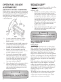
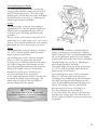
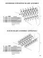
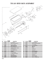
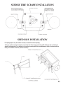
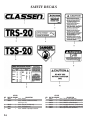
TRS-20 TURF RAKE
(Serial No. 001000 & UP)
TSS-20 TURF SEEDER
(Serial No. 001000 & UP)
OPERATORS / PARTS MANUAL
Schiller Grounds Care, Inc.
1028 Street Road • Southampton, PA 18966
Telephone: 1-800-366-6268
TABLE OF CONTENTS
INTRODUCTION ......................................2
GENERAL MAINTENANCE ......................8
Thank You ............................................................2
Read This Manual ................................................2
Warranty................................................................2
Measurements ......................................................2
Serial Numbers......................................................2
Ordering Parts ......................................................2
Directions ..............................................................2
Pre-Delivery Check List ........................................3
Delivery Check List ..............................................3
Owner’s Record......................................................3
TURF RAKE/ TURF SEEDER Maintenance ........8
Engine Maintenance..............................................8
SAFETY PRECAUTIONS ..........................4
Training ................................................................4
Preparation Safety ................................................4
Engine Safety ........................................................4
Operational Safety ................................................4
OPERATION ..............................................5
Preparation ............................................................5
Starting Engine......................................................5
Transporting TURF RAKE/ TURF SEEDER..........5
Operating TURF RAKE/ TURF SEEDER ..............5
MACHINE STORAGE ................................8
Storing TURF RAKE/ TURF SEEDER ..................8
Operation After Extended Storage ........................8
CARE FOR HYDRAULIC SYSTEM ............9
PARTS MAIN FRAME ASSEMBLY ..........10
PARTS SELF PROPELLED ASSEMBLY ....11
PARTS HANDLE ASSEMBLY ....................12
SEEDER/MULTIPURPOSE
BLADE ASSEMBLY ..................................13
SLICER BLADE ASSEMBLY ....................13
SEED BOX ASSEMBLY ............................14
SEEDER TIRE SCRAPE INSTALLATION 15
SEED BOX INSTALLATION ....................15
SAFETY DECALS ....................................16
NOTES ....................................................17
WARRANTY ............................................18
OPTIONAL BLADE ASSEMBLIES ............6
Changing Blade Assemblies ..................................6
Replacing Shaft Assembly Only ............................6
Recommended Height Adjustments......................6
INTRODUCTION
THANK YOU
MEASUREMENTS
Thank you for purchasing a CLASSEN TRS-20/
TSS-20.
U.S. Units of measure are used in this manual.
READ THIS MANUAL
Write frame and engine serial numbers, plus model
numbers in “Owner’s Record” section below. You
may need these numbers when you order parts.
The serial number sticker plate is located near
the left rear corner of the TRS-20/TSS-20 frame.
Read this manual carefully in its entirety. It
contains assembly, operating, maintenance,
adjustment instructions and a parts list for your
TRS-20/TSS-20. By following the operating and
maintenance instructions you will prolong the life
of your equipment and maintain its maximum
efficiency. Failure to do so could result in personal
injury or equipment damage. This manual
should be considered a permanent part of your
TRS-20/TSS-20 and should remain with it if you
sell it.
WARRANTY
Refer to last page.
2
SERIAL NUMBERS
ORDERING PARTS
When ordering parts, always give the serial number
and model of your TRS-20/TSS-20 as well as the
quantity, part number and description of the part
needed.
DIRECTIONS
“Right Hand” and “Left Hand” sides of the
TRS-20/TSS-20 are determined by facing the “back”
of the unit as you would operate the machine.
PRE-DELIVERY
CHECK LIST
CHECK THE FOLLOWING BEFORE YOU
DELIVER THE TRS-20/TSS-20 TO THE
CUSTOMER.
1. Guards and shields fastened in place.
2. Decals fastened and legible.
3. Gas lever on engine turned on.
4. All lubrication points greased.
5. Air cleaner.
6. Touch up scratches.
7. Add engine oil (refer to Engine manual)
8. Add fuel, start engine, test run.
DATE SET UP
__________/__________/__________
DELIVERY CHECK LIST
REVIEW THE OPERATORS MANUAL WITH
THE CUSTOMER.
1. Classen Mfg., Inc. warranty.
2. Safe operation and service.
3. How to use controls.
4. Operating the machine correctly.
5. Transporting the TRS-20/TSS-20.
6. Correct fuel and lubricants.
7. Daily and periodic inspections.
8. Changing oil after break-in period.
9. Servicing the TRS-20/TSS-20 regularly
and correctly.
10. Classen Mfg., Inc. parts and service.
11. Give the customer the Operator’s Manual
and encourage customer to read it.
DATE DELIVERED
__________/__________/__________
SIGNATURE _______________________________
OWNER’S RECORD
DATE PURCHASED
__________________________________________
TRS-20/TSS-20 SEEDER MODEL NUMBER
__________________________________________
ENGINE MODEL NUMBER
__________________________________________
TRS-20/TSS-20 SERIAL NUMBER
__________________________________________
ENGINE SERIAL NUMBER
__________________________________________
3
SAFETY PRECAUTIONS
TRAINING
1.
2.
3.
4.
5.
6.
Regard the unit as a piece of power
equipment and teach this regard to all who
operate this unit.
Read the instructions carefully. Be familiar
with the controls and the proper use of the
equipment.
Never allow children, teenagers or people
unfamiliar with these instructions to use
this piece of equipment.
Avoid operating unit while people,
especially children or pets, are nearby.
Keep in mind that the operator or user
is responsible for accidents or hazards
occurring to other people or their property.
Be sure you know how to stop the
TRS-20/TSS-20 at a moment’s notice.
When using the TRS-20/TSS-20, make
certain frame plate is attached at all times
when not bagging.
4.
5.
OPERATIONAL SAFETY
1.
2.
3.
4.
5.
PREPARATION SAFETY
1.
2.
3.
The use of personal protective equipment,
such as (but not limited to) protection for the
eyes, ears, feet and head is recommended.
While operating, always wear substantial
foot wear and long trousers. Do not operate
the equipment when barefoot or wearing
open sandals.
Area should be free of all obstacles
and debris.
6.
7.
8.
9.
ENGINE SAFETY
1.
2.
3.
Handle gasoline with care; it is highly
flammable.
Use an approved gasoline container.
Always add fuel before starting the engine.
10.
11.
WARNING
DO NOT FILL TANK COMPLETELY FULL.
DO NOT SMOKE WHILE YOU FILL FUEL TANK.
DO NOT REMOVE GAS CAP IF ENGINE
IS RUNNING.
DO NOT OPERATE ENGINE IN A
CONFINED SPACE WHERE DANGEROUS
CARBON MONOXIDE FUMES CAN COLLECT.
4
Fill the fuel tank outdoors.
If fuel is spilled, do not attempt to start the
engine. Move away from the area of the spill
and avoid creating any source of ignition
until fuel vapors have dissipated.
12.
13.
Carefully read and follow all
caution stickers.
Operate only in daylight or good
artificial light.
Do not operate machine unless all guards,
shields and covers are in place and in
proper working condition.
It is essential all operator safety mechanisms
be connected and in operating condition
prior to use.
Do not change the engine governor settings
or over-speed the engine. Operating an
engine at excessive speed may increase the
hazard of personal injury.
Disengage all blade and drive clutches
(release bail) before starting.
Start the engine carefully with feet well
away from the blades.
Do not put hands, feet or clothing near
rotating parts while the unit is being
operated.
Travel up and down slopes at a 45° angle
rather than across, to prevent unit from
tipping over.
Exercise extreme caution when changing
direction on slopes. Do not get too close
to sharp drop-offs or operate unit on
excessively steep slopes.
Use caution when backing up or pulling
the unit towards you.
Stop the blades if unit has to be tilted for
transportation, when crossing surfaces (i.e.
sidewalks, driveways, stepping stones, etc.)
or when transporting the unit to and from
the area being worked on.
Never pick up or carry a TRS-20/TSS-20
while the engine is running.
14. Stop the engine and disconnect the spark
plug wire:
a) before checking, cleaning or working
on unit
b) after striking a foreign object (inspect
the unit for damage and make repairs
before restarting and operating)
15. Stop the engine:
a) whenever you leave the unit
b) before refueling
c) before clearing blockages.
16. Reduce the throttle setting during engine
run-out and, if the engine is provided with
shut-off valve, turn the fuel off at the
conclusion of operating.
17. Before shutting off, put drive lever in neutral.
2.
3.
4.
5.
6.
7.
8.
Turn choke on (closed).
Turn ignition switch to “on”.
Move throttle control to high RPM setting.
Do not exceed 3600 rpm.
Pull recoil starter rope until engine starts.
After engine is warm, turn off choke (open).
Allow engine to run one minute before
operating.
Check engine rpm setting before operating,
DO NOT exceed 3600 rpm.
TRANSPORTING THE TRS-20/
TSS-20
OPERATION
Engage
PREPARATION
1.
2.
3.
4.
5.
6.
7.
8.
Carefully read this manual and operate
TRS-20/TSS-20 correctly.
Always check machine on level ground.
Visually check all moving parts and all
fasteners, if loose or broken, tighten or
replace. Check for broken or bent blades,
replace if necessary.
Lubricate all fittings after every four hours
of using machine, using a pressurized gun
with standard lithium base lubricant (see
“General Maintenance” section). Wipe off
fittings before and after lubricating.
Add oil to the engine crankcase with engine
resting in a level position (refer to engine
manufacturer’s Owner’s Manual for the
correct type and amount of oil).
Fill the fuel tank according to engine
manufacturer specifications.
Police lawn area for obstacles and debris
(i.e. sprinklers, hoses, toys, etc.)
Mark underground sprinkler heads and
other hidden obstacles to prevent damage.
STARTING ENGINE
Disengage
Fig. 1
1.
2.
3.
4.
5.
1.
Turn fuel cock to the “open” position
Position height adjustment lever to the
start/transport position (see Fig. 1).
Start motor , Run motor at one half
throttle.
Engage top bail.
Select speed lever.
Bottom bail up for engagement for main
shaft
OPERATING THE TRS-20/TSS-20
1.
2.
3.
4.
5.
6.
CAUTION
TO AVOID INJURY, DO NOT PLACE YOUR FEET
OR OTHER BODY PARTS UNDER THE BLADES
WHILE STARTING THE ENGINE.
Fig. 2
7.
Put speed lever in neutral position
Start engine
Engage top bail
Select forward or reverse with the
speed lever.
Drive TRS-20/TSS-20 to the area to be
raked or seeded.
Move height adjustment lever to the
appropriate setting for the shaft assembly
being used.(see ''optional shaft assemblies''
section)
Lift bottom bail to engage the main shaft.
Release bail to stop
5
OPTIONAL BLADE
ASSEMBLIES
CHANGING BLADE ASSEMBLIES
Within minutes your machine can be converted to
a turf rake, turf seeder or turf slicer by purchasing
the optional blade assemblies available complete
with side plates, bearings and drive pulley.
Changing the blade assembly can be done quickly
as described below.
REPLACING SHAFT
ASSEMBLY ONLY
If replacing the existing shaft assembly, only follow
steps 1 through 3 above. Proceed with the
following steps.
1. Remove the two drive pulleys and bearing
plates from the main shaft (one on each
side). Replace with new shaft. Reinstall the
bearing plates and drive pulleys on the new
shaft using Pro Lock (retaining 1, medium
strength) on the shaft and Pro Lock (nut
type, medium strength) on the set screws.
The pulleys will be positioned on the shaft
by bolts, the 1/4” lock washer and the
pulley retainer washer.
2. Route the belt behind the idler pulleys and
roll the belts onto the lower pulleys then
reinstall the belt shields.
WARNING
Fig. 3
1.
2.
3.
4.
5.
Set unit up on block allowing enough
distance beneath machine to change
blade assembly.
After removing the belt shield, remove the
twelve bolts on the left side and three on
the right side which hold the blade
assembly to the main body (see Fig. 3).
Remove the belts from both sides and
remove the entire blade assembly. There is
no need to loosen any set screws.
Next install the optional blade assembly
and fasten with six 1/4” x 5/8” bolts on
each side. Tighten all bolts on both shields.
Center the shaft and tighten the two set
screws in each bearing using Pro Lock
(nut type, medium strength).
When changing back to the original shaft it
will not be necessary to loosen any set
screws. Only the bolts in the belt shields
and the eight bolts holding the shaft will
need to be removed.
CAUTION
BE CERTAIN THAT THE SET SCREWS ARE
TIGHTENED PROPERLY IN BEARINGS AND PULLEY
WHEN REASSEMBLING.
6
CAUTION: BE CERTAIN THAT THE SET SCREWS
ARE TIGHTENED PROPERLY IN BEARINGS AND
PULLEY WHEN REASSEMBLING.
RECOMMENDED HEIGHT
ADJUSTMENTS
Raking Height
When using the Turf Rake with its raking (flail)
blade assembly adjust the raking height as follows.
Normal height is set by placing the Turf Rake on a
hard surface making sure one satellite shaft is at
dead bottom. Adjust the wheels so the raking
fingers on the bottom shaft just touch the ground.
DO NOT set the fingers so that they will penetrate
the ground as this will counteract the centrifugal
force of the fingers and prevent the from raking
properly.
With repeated use, raking side of the fingers will
begin to wear. To give the fingers a new square
raking edge, remove the end plates and turn the
entire main shaft assembly 180° and replace it on
the Turf Rake. NOTE: Use Pro-Lock (retaining 1,
medium strength) on the 7” pulley on the
main shaft.
To prolong the life of the main shaft, extra holes
are provided. If the circular holes holding the
satellite shafts become distorted, rotate all four
satellite shafts to the next set of holes.
Seeding/Multipurpose Height
The seeding/multipurpose blades are used for
cutting grooves for over-seeding and can also be
used for verticutting grasses. To set the height
properly place unit on the lawn surface and adjust
the wheel height up (see Fig. 4 ). Adjusting the
wheel height up lowers the blades.
Seeding
The proper height setting for over-seeding is
approximately 1/4” into the ground. Adjust the
wheel height up approximately one notch. If
set deeper, grass seed being applied may not
germinate.
For best results, over-seed in two passes of 1/2
application rate at right angles or in a criss-cross
pattern. Water heavily immediately after seeding
then lightly for 10-14 days keeping soil moist.
Slicing
The proper height setting for slicing or aerating is
1/2” to 3/4” into the ground. Adjust the wheel
height up one or two notches.
For crawling grasses such as Zoysia, Bermuda,
Bahia, etc. raise the wheels only one notch.
Crawling grasses should not be sliced too deeply.
For single strand grasses like Bluegrass or Rye,
aerate in perpendicular directions for more even
slicing. For example, slice in a North-South
direction on the first pass, switching to an
East-West direction on the second pass.
As the seeder/multipurpose blades wear they may
be rotated to provide a new cutting edge. The
wheels may be raised to allow the blades to
penetrate deeper into the ground.
CAUTION
BE CERTAIN THAT THE SET SCREWS ARE
TIGHTENED PROPERLY IN BEARINGS AND PULLEY
WHEN REASSEMBLING.
Fig. 4
Slicing Height
The slicer blade assembly is recommended for
slicing, verticutting or aerating when a thinner
blade is preferred. This is the recommended blade
for use on golf course greens. To set the height
properly place unit on the lawn surface and adjust
the wheel height up (see Fig. 4). Adjusting the
wheel height up lowers the blades.
The proper height setting for slicing or aerating is
1/2” to 3/4” into the ground. Adjust the wheel
height up one or two notches.
For crawling grasses such as Zoysia, Bermuda,
Bahia, etc. raise the wheels only one notch.
Crawling grasses should not be sliced too deeply.
For single strand grasses like Bluegrass or Rye,
aerate in perpendicular directions for more even
slicing. For example, slice in a North-South
direction on the first pass, switching to an
East-West direction on the second pass.
As the slicer blades wear they may be rotated to
provide a new cutting edge. The wheels may be
raised to allow the blades to penetrate deeper into
the ground.
7
GENERAL
MAINTENANCE
TO KEEP THE TRS-20/TSS-20 IN
GOOD OPERATING CONDITION,
PERFORM THE FOLLOWING:
•
•
•
•
•
•
•
•
When replacement parts are required, use
genuine Classen parts or parts with
equivalent characteristics including type,
strength, and material. Failure to do so may
result in product malfunction and possible
injury to the operator and/or bystanders.
Keep all safety decals legible. Remove all
grease, dirt and debris from decals. Any
safety decal that becomes illegible should
be replaced immediately (see ‘Safety
Decals” section). Safety decals can be
affixed by peeling off the backing and
applying to clear, dry surface. Smooth
out to remove any air bubbles.
Do not operate equipment without shields
in place.
Do not make any adjustments or perform
any maintenance while the engine is
running.
Check engine mounting bolts frequently to
maintain proper tightness.
Thoroughly clean off blades when
application is completed and apply a light
coat of oil to prevent rust on blades.
Keep belt free of oil and dirt.
Check for worn or deteriorating
components that could create a hazard.
When new components are installed, be
sure that current safety decals are affixed to
the replaced components. Safety decals can
be affixed by peeling off the backing and
applying to clear, dry surface. Smooth out
to remove any air bubbles.
ENGINE MAINTENANCE
•
•
•
8
Refer to engine manufacturer’s
Owner’s Manual.
Check engine oil level with engine resting
in a level position.
Inspect air filter element and replace if
necessary.
•
If carburetor adjustment is necessary, stand
to one side and keep feet and hands clear
while making adjustments.
MACHINE STORAGE
SAFETY WARNING
TO PREVENT POSSIBLE EXPLOSION OR IGNITION
OF VAPORIZED FUEL, DO NOT STORE EQUIPMENT
WITH FUEL IN TANK OR CARBURETOR OR NEAR
OPEN FLAME (I.E. FURNACE, WATER HEATER,
PILOT LIGHT).
STORAGE INSTRUCTIONS
Before the TRS-20/TSS-20 is put into storage for
any period exceeding 30 days, the following steps
should be taken.
1. Drain all fuel from fuel tank and fuel lines.
2. Start engine and run until all fuel is used
from carburetor float bowl.
3. While engine is still warm, drain the
crankcase oil and replace with the proper
weight oil corresponding to the season the
TRS-20/TSS-20 will next be used (refer to
engine manufacturer’s Owner’s Manual).
4. Remove the spark plug and squirt a small
quantity of engine oil into the cylinder.
Turn the engine over a few times to
distribute that oil.
OPERATION AFTER EXTENDED
STORAGE
To put TRS-20/TSS-20 into operation after an
extended storage:
1. Check for loose parts and tighten
if necessary.
2. Check for cracked or broken blades
and replace,
3. Check that all safety decals are in place
and legible.
4. Fill fuel tank.
5. Check engine oil level with engine in level
position (refer to engine manufacturer’s
Owner’s Manual).
6. Start engine.
7. Check for fuel leaks.
CARE FOR HYDRAULIC SYSTEM
To keep the hydraulic system in working order,
there are a few steps needed to take place. If
synthetic oil were used we would suggest a full
synthetic oil such as Mobil 1 15W50, Quaker
State Full Synthetic 5W50, or a similar oil.
Oil viscosity is very important to transmission
life. For optimum performance the oil viscosity
should maintain a viscosity of 13 cSt [70 SUS].
The minimum oil viscosity to prevent component
wear is 9 cSt [55 SUS]. These Viscosity
requirements are for an oil temperature of 110
degrees Celsius [230 degrees Fahrenheit]
Typically; standard SEA 20W-50 multi-viscosity
motor oils will meet this requirement. If the
operating temperature is elevated then synthetic
oil with greater viscosity index, or more viscosity
at elevated temperatures, may be needed to meet
viscosity requirements.
System Start-up: (purging air from system).
Factory Fills unit with SAE 20W-50 multiviscosity
motor oil. This will need to be checked when
setting up with instructions below.
At system start-up, several things need to be
accomplished to ensure a properly running
system.
1. Fill the BDU case and expansion level and
ensure they do not empty during the
following procedure.
2. Start engine and increase throttle to at least
2/3 speed.
3.
4.
5.
6.
7.
8.
9.
10.
11.
12.
13.
14.
15.
Open bypass valve by depressing bypass
plunger and holding.
Adjust control linkage such that
transmission control is stroking
full forward.
Move and hold control in forward for
3 seconds; repeat two additional times.
Close bypass valve be releasing
bypass plunger.
With engine still at same speed,
repeat step 5.
Move control to neutral.
Check engine speed. Adjust to
recommended maximum engine speed.
Adjust neutral position.
Adjust forward control stop to
recommended axle speed.
Adjust reverse control stop to
recommended axle speed.
If axle speed is not achieved ensure
linkage allows proper movement of
transmission control.
If transmission control lever is rotating
fully but recommended axle speed is not
achieved, repeat start-up procedure.
Refill expansion tank oil to
recommended level.
9
PARTS MAIN FRAME ASSEMBLY
10
PARTS SELF PROPELLED ASSEMBLY
11
PARTS HANDLE ASSEMBLY
12
SEEDER/MULTIPURPOSE BLADE ASSEMBLY
KEY
1
2
3
4
5
6
QTY/PER
PART NO. MACHINE
700025
1
100310
26
500216
52
500217
52
600030
1
900026
1
DESCRIPTION
Shaft w/ Blade Holders, Multipurpose
Blade w/ 15/16” Holes, Multipurpose
Bolt, 5/16-18 x 314 Grade 8
Nut, 5/16-18 Tap Lock
Shaft/Blades Sub-Assembly, Multipurpose
Complete Multipurpose Shaft Assembly
(Includes Shaft, Blades, End Plates,
Bearings, Pulley, Key & Fasteners)
- Not Shown
SLICER BLADE ASSEMBLY (OPTIONAL)
KEY
1
2
3
4
5
6
QTY/PER
PART NO. MACHINE
700025
1
300032
26
500180
52
500160
52
600024
1
900016
1
DESCRIPTION
Shaft w/ Blade Holders, Multipurpose
Blade, Slicer Square
Bolt, 1/4-20 x 3/4 Grade 8
Nut, 1/4-20 Top Lock
Shaft/Blades Sub-Assembly, Multipurpose
Complete Slicing Shaft Assembly
(Includes Shaft, Blades, End Plates,
Bearings, Pulley, Key & Fasteners)
- Not Shown
13
TSS-20 SEED BOX ASSEMBLY
KEY
1
2
3
4
5
6
7
8
9
10
11
12
13
14
15
16
17
14
QTY/PER
PART NO. MACHINE
500068
8
100140
1
500089
2
100142
1
100141
1
500118
3
100139
1
100127
1
100229
3
100144
2
100357
1
500226
1
100355
2
100067
2
400038
1
100078
1
400039
1
DESCRIPTION
1/4” NYLOC NUT
GAUGE w/ BOLT & WING NUT
1/4” x 1-1/2” BOLT
CONTROL LEVER GRIP
CABLE CONTROL LEVER
1/4” x 1-3/4” BOLT
CONTROL CABLE (NOT SHOWN)
FRICTION WASHER
#8 x 3/4” BLACK SCREW
HOUSING CLIP
SEED BOX
3/16 LOCK WASHER
8” SEED BOX DRIVE WHEEL
SHAFT GUARD
MOUNTING BRACKET
VINYL SEED BOX COVER
STABILIZING BRACKET
KEY
18
19
20
21
22
23
24
25
26
27
28
29
30
31
32
33
34
QTY/PER
PART NO. MACHINE
500088
10
900033
1
500069
3
500227
1
300116
1
400209
1
100356
2
500223
2
500224
3
100358
2
100359
1
100074
1
500225
1
100020
1
400040
2
500096
1
500016
1
DESCRIPTION
1/4” FLAT WASHER
COMPLETE SEED BOX ASSEMBLY
1/4” x 5/8” BOLT
3/16” FLAT WASHER
SIDE PLATE
AXLE
BEARING
3/16 x 1” BOLT
3/16” NUT
SHUT-OFF END CLIP
SHUT-OFF ASSEMBLY
DECAL, “CLASSEN”
3/16” x 3/4” BOLT
PLASTIC TIE
CONNECTING PINS
5/32” x 3” HAIR PIN
5/32” x 1-1/4” COTTER PIN
SEEDER TIRE SCRAPE INSTALLATION
SEED BOX INSTALLATION
For shipping purposes only, the seed box assembly is attached to machine improperly.
To set your machine correctly for operation, remove hairpin clip (A) from upper connecting rod (B). Slide upper rod out, allowing “A
shaped” stabilizing bracket (C) on seed box to sit over lower connecting rod. (When mounted properly, wheels of seed box should be
resting on front wheels of machine.) Reinsert rod and clip.
15
SAFETY DECALS
QTY/PER
KEY PART NO. MACHINE
DESCRIPTION
1
100074
2
Decal, “Classen”
2
100060
1
Decal, “CAUTION - Muffler and Shields
May Exceed 150°”
3
100340
1
Decal, “TRS-20” (Turf Rake only)
4
100071
1
Decal, “Bail Engagement”
5
100061
1
Decal, “CAUTION - Operating Instructions”
16
KEY
6
7
8
9
10
11
QTY/PER
PART NO. MACHINE
DESCRIPTION
100341
1
Decal, “TSS-20” (Turf Seeder only)
100069
1
Decal, “DANGER, Keep Hands and Feet Away”
100070
1
Decal, “DANGER - Carbon Monoxide”
100138
1
Decal, “Seed Application Chart” (Turf Seeder only)
100228
1
Decal, “CAUTION - Catcher Bag (Turf Rake only)
100054
1
Manual, Operators/Parts (Not Shown)
NOTES
17
Schiller Grounds Care, Inc.
1028 Street Road • Southampton, PA 18966
Telephone: 1-800-366-6268
TWO YEAR LIMITED WARRANTY
Effective April 1, 2007
For the period of two years from the date of purchase, CLASSEN MFG., INC. will repair or replace for the original purchaser free
of charge, any part or parts found upon the examination of our factory authorized service station, or by the factory in Norfolk,
Nebraska, to be defective in material or workmanship. All transportation charges on parts submitted for repair or replacement under
this warranty shall be borne by the purchaser.
This warranty does not include engines or engine parts, tires, batteries, or gearboxes that are covered under separate warranties
furnished by their manufacturer or supplier, nor does it include normal maintenance parts, including but not limited to, spark plugs,
points, filters, blades, and lubricants.
All service under this warranty will be furnished or performed by our factory authorized service stations.
There is no other expressed warranty. Implied warranties, including those of merchantability and fitness for a particular purpose, are
limited to two years from the date of purchase and to the extent permitted by law, any and all implied warranties are excluded. The
above remedy of repair and replacement of defective parts is the purchaser’s exclusive remedy for any defect, malfunction or breach
of warranty. Liability for incidental or consequential damages under any and all warranties is excluded to the extent permitted
by law.
NORMAL RESPONSIBILITIES OF THE SELLER AND THE USER
1.
The Distributor or Dealer is responsible for the proper assembly and preparation of the product for delivery to the end user.
2.
The User is responsible for reading the Manual and Instructions.
3.
The User is responsible for proper operation and maintenance as described in the manual.
4.
The User is responsible for the replacement of wear items such as blades, belts, tires, batteries, etc.
5.
The User is responsible for damage due to improper operation and maintenance, as well as abuse.
All claims must be received by the factory 30 days after the end of the warranty period to receive warranty consideration.
© 2009 Schiller Grounds Care, Inc. All Rights Reserved.
9/09