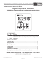
1
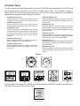
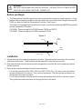
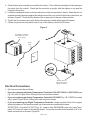
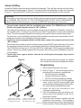
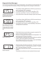
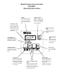
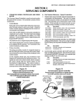
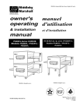
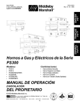
Middleby Cooking Systems Group • 1400 Toastmaster Drive • Elgin, IL 60120 • USA • (847) 741-3300 • FAX (847) 741-4406
Instructions for Service Kit 58504
Digital Temperature Controller
Installation, Programming and Troubleshooting Instructions
KIT COMPONENTS
Qty.
P/N
1
58388
1
58955
Description
Digital Temperature Controller (On/Off Gas & Electric, PID Gas, and
Variable Pulse Electric operating modes), with mounting brackets
Instructions
TABLE OF CONTENTS
Controller Types ............................................................................................... 2
Before You Begin ............................................................................................. 3
Installation ........................................................................................................ 3
Electrical Connections ..................................................................................... 4
Jumper Setting ................................................................................................. 6
Programming ................................................................................................... 6
Diagnostic Error Messages ............................................................................. 8
Operating Instructions (to be left with customer after installation) ...................... 9
Middleby Cooking Systems Group • 1400 Toastmaster Drive • Elgin, IL 60120
(847) 741-3300 • FAX (847) 741-4406
© 2002 Middleby Marshall. cjz
P/N 58955 • Rev. B• V3 • 1/06
Page 1 of 10
Controller Types
This Kit includes one Digital Temperature Controller (P/N 58388) that can operate at 120-240V, and
can be programmed to operate in on-off, PID, or variable pulse modes. The Controller is shown in
Figure 1G, below. By following these instructions, the Controller can be installed into any Middleby
Marshall oven equipped with the following Controllers.
•
P/N 28071-0012 (Fig. 1A)
Analog Temperature Controller without high-limit and
cooldown functions, operating at 120V, on-off mode only.
•
P/N 28071-0018 (Fig. 1A)
Analog Temperature Controller with high-limit and
cooldown functions, operating at 120V, on-off mode only.
•
•
•
P/N 34983 (Fig. 1B)
Analog Temperature Controller without high-limit and
cooldown functions, operating at 120V, on-off mode only.
Used on PS200VL models. As of 12/01, P/N 34983 is
still available and should be used on these ovens if
possible.
P/N 28071-0027 (Fig. 1C)
Digital Temperature Controller with blue plastic faceplate, operating at 120V, on-off mode only.
P/N 28071-0028 (Fig. 1D)
Digital Temperature Controller with gray rubber faceplate and buttons with text, operating at 120V, on-off
mode only.
•
P/N 28071-0028 (Fig. 1E)
Digital Temperature Controller with gray rubber face
plate and buttons with symbols, operating at 120V, onoff mode only.
•
P/N 30871 (Fig. 1E)
Digital Temperature Controller with gray rubber face
plate and buttons with symbols, operating at 208-240V,
on-off mode only. Used on early PS360WB70 and some
CE oven models.
•
P/N 32571 (Fig. 1E)
Digital Temperature Controller with gray rubber face
plate and buttons with symbols, operating at 208-240V,
PID mode only. Used on early PS360EWB.
•
P/N 36021 (Fig. 1F)
Digital Temperature Controller with gray face plate (steel
trim on edges), operating at 120-240V, selectable onoff or PID modes.
•
P/N 36056 (Fig. 1G)
Digital Temperature Controller with black plastic face
plate, operating at 120-240V, selectable on-off or PID
modes.
Figure 1
A
C
D
B
E
F
G
This Kit CANNOT be installed in a PS536 oven equipped with the P/N 44783 (variable pulse electric) or
P/N 44823 (PID gas) controller shown below.
H
Page 2 of 10
WARNING
BEFORE PERFORMING ANY SERVICE WORK, THE ELECTRICAL POWER SUPPLY
AND THE GAS SUPPLY MUST BE TURNED OFF.
Before you Begin
1. This Temperature Controller requires a current-version thermocouple for proper operation. Check
that the thermocouple(s) installed in the oven match the current three-lead, flanged versions BEFORE you begin to install the Temperature Controller. See Figure 2.
If the oven is not equipped with current thermocouples, you should replace them BEFORE you install
the new Temperature Controller.
P/N 33984: Thermocouple kit for PS300-series, PS555 and PS570
P/N 33985: Thermocouple kit for PS200-series and PS536
Figure 2
Cable
(3 leads)
flange
Current thermocouple
Cable
(2 leads)
Obsolete 2-lead
thermocouple
clip
Installation
1. Access the back of the existing temperature controller. Tag each wire that connects to the controller
with its terminal number. These numbers will be used later to wire the new controller.
2. Disconnect all wires from the terminals on the temperature controller. Be sure to retain any jumpers
that are removed.
3. Remove the controller and sleeve from the oven as follows:
• For analog controllers P/Ns 28071-0012 and 28071-0018 (Fig. 1A), remove the two bracket
screws on the back of the control. Then, remove the bracket. Pull the controller and sleeve out
through the front of the oven panel.
• For all other controllers, remove the two screws and brackets that hold the controller in place.
Then, pull the controller and sleeve out through the front of the panel.
Page 3 of 10
4. Check that the new controller is mounted into its sleeve. Then, slide the assembly into the opening in
the panel from the outside. Check that the controller is upright, with the display on top and the
keypad on the bottom.
5. Locate the rectangular holes on the top and bottom of the new controller’s sleeve. Attach the two kitsupplied mounting brackets against the inside panel of the oven, and into the holes in the sleeve, as
shown in Figure 3. Check that the heads of the screws point to the rear of the controller.
6. Tighten the two screws evenly until the lip of the sleeve is seated tightly against the panel.
7. If there is a protective clear plastic strip on top of the display, remove it at this time.
Figure 3
Temperature controller is
pre-installed into sleeve
and is upright
Control
panel
Bracket clips and
screw heads point to
REAR of controller
Electrical Connections
1. Wire the new controller as follows:
• If you are replacing an Analog Temperature Controller, P/Ns 28071-0012 or 28071-0018 (see
Fig. 1A), refer to Figure 4A for a listing of the new terminal numbers.
• If you are replacing an Analog Temperature Controller P/N 34983 (Fig. 1B - PS200VL models
only), refer to Figure 4B for a listing of the new terminal numbers.
• If you are replacing any Digital Temperature Controller, simply reconnect ALL of the original
wires and jumpers to the same terminals, as all terminals are numbered the same.
EXCEPTION: Controller P/N 32571(Fig. 1E - used on early PS360EWB ovens only) uses Terminals 4 & 5 for the mA output to the amplifier board. The current controller uses Terminals 15 & 16 for
these connections, as shown in Figure 5A.
Page 4 of 10
Figure 4a
Figure 4b
Analog temperature controller (P/Ns
28071-0012 and 28071-0018) terminals
Analog temperature controller
(P/N 34983) terminals
New temperature
controller terminals
New temperature
controller terminals
Not used on
some gas and
electric ovens
Not used
Not used. PS200VL
ovens have a separate high limit module
and do not include a
cooldown feature.
Not used
Not used
Not used
Not used. PS200VL
ovens do not include a
modulating gas system.
Not used. These
terminals provide PID
output (gas ovens
with
modulating
valve) or variable
pulse output (electric ovens with
variable pulse system). Neither of
these systems were available with
ovens equipped with these
controllers.
Terminal for
28071-0012 and
28071-0018
1
2
5
6
L2
L1
G
13
14
15
16
---
Terminal for
34983
TC+
TCCOM
NO
L2
L1
G
-------
Terminal for
46837
8
7
5
4
L2
L1
9
10
11
12
15
16
Description
+ TC
- TC
Input to Temperature Control Relay
Output to High Flame Solenoid or Heater Contactors
Neutral
Power
Ground
Input to Cooldown Relay
Output from Cooldown Relay
Input to High Limit Relay
Output from High Limit Relay
PID or Variable Pulse Output
PID or Variable Pulse Output
Figure 5a
Figure 5b
Modulated Gas Output System
Variable Pulse Output System
4-20mA
input
Amplifier board
Modulating
valve
Relay
20VDC pulsed output
0-24VDC
output
NOTE: Controller P/N 32571 used Terminals 4 & 5
for the 4-20mA input to the amplifier board.
These connections must be moved to Terminals
15 & 16 on the new controller as shown.
NOTE: Safety switches
may be placed between
the temperature controller
and the relay on some
oven models.
24VAC
input
Page 5 of 10
Jumper Setting
Loosen the Phillips screw at the bottom center of the faceplate. Then, pull the controller out of its sleeve.
Next, access the jumper shown in Figure 6. This jumper affects the signal that is output from Terminals
15 and 16. The jumper MUST be set to the correct position for proper operation of the controller.
CAUTION
If the jumper is incorrectly set, the oven will be unable to properly maintain temperature. In addition, DAMAGE MAY OCCUR TO THE CONTROLLER AND OTHER OVEN COMPONENTS.
Always make sure that the jumper is correctly set BEFORE restoring power to the oven!
•
•
•
For gas ovens equipped with the modulating gas system, For PS540 Electric & PS555
Electric, the jumper must be set to the “W1” position.
This instructs the controller to send a variable-current 4-20 mA signal from Terminals 15 and 16 to
the amplifier board. The board converts this to a 0-24VDC signal which is sent to the modulating
valve. The valve regulates the gas flow according to the need for heat to maintain the set point.
For gas ovens, you should always check inside the machinery compartment to see whether a modulating valve is present in the unit before setting this jumper.
For electric ovens equipped with the variable pulse system, the jumper must be set to the
“W2” position.
This instructs the controller to send a constant-current, pulsed 20VDC signal to the relay. Once every
four seconds, the signal “pulses” on proportional to the need for heat to maintain the set point.
The PS536 Electric oven (as of 1/02), the PS520E & the Blodgett 1820S uses the variable pulse
system. Other oven models equipped with this system will be announced by Middleby as they become available.
For all other ovens - gas or electric - that use the on-off system, the jumper may be set to
either position.
Figure 6
After the jumper has been properly set, replace
the controller into its sleeve and tighten the screw.
Programming
Jumper is set to the “W1”
position for gas ovens with
modulating gas system
Jumper is set to the “W2”
position for electric ovens
with variable pulse system
1. Restore electrical power to the oven.
2. Refer to Figure 7. Set the following options,
according to the customer’s preferences:
• Set Point locked or unlocked
• Degrees Fahrenheit or Celsius
• Set Point or Actual Temperature display
3. Set the controller to PID or On-Off operating
mode. Choose the PID mode for BOTH gas
ovens with the modulating system AND for electric ovens with the variable pulse system.
4. Adjust the Set Point according to the
customer’s specifications.
5. If the PID operating mode was chosen, perform an Auto-Tune calibration as per the instructions in Figure 7.
6. Check that the customer is familiar with the
operation of the controller. The last page of
these instructions includes an operating guide
Page 6 of 10
for the controller. Remove this page and leave
Page 7 of 10
Figure 7
Temperature Controller Service Instructions
Diagnostic Error Messages
The controller runs background tests during normal operation. If any problems occur during the tests, an
error message flashes in the display. A listing of these diagnostic error messages is shown below.
Flashes on the display (alternating with the temperature)
indicating that the internal diagnostic test has failed.
The oven temperature has
not reached 200°F/93°C
within 15 minutes of startup.
On gas ovens, this is usually
a result of the burner not lighting.
Caused by an open in the
thermocouple circuit.
Polarity of the thermocouple
leads is reversed.
1. Turn the Blower Switch (HEAT Switch for PS536 ovens with the twoswitch configuration) OFF for 2 minutes.
2. Turn the Blower Switch (or HEAT Switch, as per Step 1) ON.
3. If necessary, repeat Steps 1 and 2 up to two additional times.
4. If the problem does not clear after 3 attempts, replace the controller.
1. Turn the Blower Switch (HEAT Switch for PS536 ovens with the twoswitch configuration) OFF for 2 minutes.
2. Turn the Blower Switch (or HEAT Switch, as per Step 1) ON.
3. If the problem does not clear, contact the Middleby Technical Service Department for assistance.
1. Check that the thermocouple leads are properly connected to Terminals 7 & 8 of the temperature controller.
2. Check the continuity of the thermocouple at room temperature. You
should measure 9-20 Ohms of resistance.
3. If the reading was outside the correct range, the thermocouple has
an open. Remove and replace the thermocouple.
If the reading was inside the correct range, contact the Middleby
Technical Service Department for assistance.
1. Check the polarity of the thermocouple leads. The red wire (-) should
be attached to Terminal 7 on the temperature controller. The white
wire (+) should be attached to Terminal 8.
2. If the polarity connections are incorrect, connect the thermocouple
properly.
If the polarity connections are correct, replace the thermocouple.
Page 8 of 10
Digital Temperature Controller
P/N 46837
Operating Instructions
Display
Shows the Set Point or
the Actual Temperature in degrees Fahrenheit (F) or Celsius
(C).
"HEAT ON" Light
Lights when the
burner or heating elements, as appropriate
for the oven model,
are in operation.
"SP LOCK" Light
Lights when the set
point is locked out
from changes. This
setting can only be
changed by service
personnel.
"SET PT" (setpoint)
Light
Lights when the set
point is shown in the
display.
"ACTUAL TEMP"
Light
Lights when the
Actual Temperature is shown in
the display.
OVERTEMP Light
Lights when the oven
temperature is greater
than 650°F (343°C).
Temperature Key
Press this key once to
view the Actual Temperature in the Display.
Unlock Key
Press this key together
with the Set Point Key
to allow the Set Point
to be changed. Changes
can only be made for
60 seconds.
Service Key
For use by service personnel
only.
Up Arrow and Down Arrow
Keys
Press these keys to adjust
the Set Point up or down. If
the Set Point will not
change, refer to Set Point
Key and Unlock Key.
Set Point Key
Press this key together
with the Unlock Key to
allow the Set Point to
be changed.
Changes can only be
made for 60 seconds.
Middleby Cooking Systems Group • 1400 Toastmaster Drive • Elgin, IL 60120
(847) 741-3300 • FAX (847) 741-4406