1
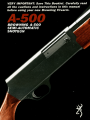
New Gun Owner’s Record
(KEEP THIS RECORD FOR FUTURE REFERENCE)
Browning Model
Serial Number
Gauge
Purchase Price
Purchased From
Date of Purchase
Please fill out and mail the Market Survey Card at the back of this booklet.
We are pleased that you have chosen a
Browning A-500 shotgun.
It is certainly a gun you can be proud to own. It
represents the state-of-the-art in modern gun design
and manufacturing. The processes of design, testing
and manufacturing were all assisted by advanced
computer systems. The result is superior dependability,
greater ease-of-operation, smoother handling and
more reliable overall function. With a reasonable
amount of care, your A-500 shotgun should give you
many years of dependable, enjoyable service. Please
feel free to write us immediately if you have any
observations regarding its performance and operation.
Also, please take a moment to complete and mail in
the brief attached marketing survey card found on our
back cover. It helps us considerably in our constant
effort to provide you with better service.
NOTE: All current production A-500 shotguns have an
improved trigger group assembly. You can confirm this
by the letter “H” stamped on the trigger guard. (See
Figure 10 on page 37 of this manual.)
If your trigger guard does not have the letter “H”
stamped on it then please contact our Browning
Service Department toll free at 1-800-322-4626 for
information on how to get the improved trigger
assembly installed on your A-500.
Thank You.
Route #1 Morgan, Utah 84050
Distributed in Canada by Browning Canada Sports Ltd./Ltee, St-Laurent, Quebec H4S 1SO
1
You Are Responsible for Firearms
Safety
As a gun owner, you accept a set of demanding
responsibilities. How seriously you take these
responsibilities can be the difference between life
and death. Mistakes made with guns are final
and cannot be paid for with money or regret.
There is no excuse for careless or abusive
handling of any firearm. At all times handle your
shotgun and any other firearm with intense
respect for its power and potential danger.
PLEASE READ AND UNDERSTAND ALL OF
THE CAUTIONS, PROPER HANDLING
PROCEDURES
AND
INSTRUCTIONS
OUTLINED IN THIS BOOKLET BEFORE
USING YOUR NEW FIREARM.
ALWAYS KEEP THE MUZZLE OF YOUR
SHOTGUN POINTED IN A SAFE
DIRECTION even though you are certain
the shotgun is unloaded. Never point any
firearm at anything you do not intend to
shoot. Be extremely alert and aware of all
persons and property within the range of
your
ammunition.
NEVER TRUST YOUR SHOTGUN’S
MECHANICAL
“SAFETY” DEVICE. The
2
word “safety” describes a gun’s trigger
block mechanism, sear block mechanism,
hammer block mechanism or firing pin
block mechanism. These mechanical
devices are designed to place your gun in
a SAFER status. No guarantee can be made
that the gun will not fire even if the
“safety” is in the “on safe” position. The
A-500 has a cross bolt “safety” which
blocks the gun’s trigger. See “Operation of
the Safety” on page 15 for instructions on
operation of this gun’s safety.
Like any mechanical device, a “safety” can
sometimes fail; it can be jarred or
inadvertently manipulated into an unsafe
condition. Mechanical “safeties” merely aid
safe gun handling and are no excuse for
pointing your shotgun’s muzzle in an
unsafe direction.
While it is a good idea to “test” your
shotgun’s mechanical “safeties” periodically
for proper function, NEVER TEST THE
“SAFETY” WHILE YOUR SHOTGUN IS
LOADED OR POINTED IN AN UNSAFE
DIRECTION.
Safe gun handling does not stop with your
gun’s mechanical “safety” devices — it
starts there. Always treat this shotgun with
the respect due a loaded, ready-to-fire
firearm.
3
WHENEVER YOU HANDLE A FIREARM,
OR HAND IT TO SOMEONE, ALWAYS
OPEN THE ACTION IMMEDIATELY,
VISUALLY CHECK YOUR SHOTGUN’S
CHAMBER, FEED MECHANISM AND
MAGAZINE to be certain that they do not
inadvertently contain any ammunition.
Always keep the chamber empty and the
“safety” in the “on safe” position unless
shooting is imminent.
DO NOT TRANSPORT YOUR SHOTGUN
LOADED, WHETHER IN A SCABBARD
GUN CASE, OR OTHER CONTAINER.
BEWARE
OF
BARREL
OBSTRUCTIONS,
for the safety of both your gun and
yourself. Mud, snow, and an infinite variety
of other objects may inadvertently lodge in
a barrel bore. It takes only one small
obstruction to cause dangerously increased
pressures that can ruin (swell or rupture)
the finest shotgun barrels.
BEFORE CHECKING FOR A BARREL
OBSTRUCTION, BE CERTAIN NO LIVE
ROUND IS IN THE CHAMBER AND
THAT THE MAGAZINE AND FEED
MECHANISMS
ARE
COMPLETELY
EMPTY. PLACE THE “SAFETY” IN THE
“ON SAFE” POSITION (See page 28 for
4
instructions
on
unloading).
After
assuring
yourself that the shotgun is completely empty,
again, open the breechblock, locking it to
the rear, and look through the barrel to be
sure it is clear of any obstruction. If an
obstruction is seen, no matter how small it
may be, clean the bore with a cleaning rod
and patch as described in “Cleaning and
Maintenance Suggestions” on page 54.
Before the first firing, clean the bore with a
cleaning rod and patch, and wipe away
any anti-rust compounds in the action/
chamber
areas.
ALWAYS UNLOAD YOUR SHOTGUN WHEN
NOT IN USE. REFER TO PAGE 28 OF THIS
INSTRUCTION
BOOKLET
EXPLAINING
THE UNLOADING OF YOUR SHOTGUN.
As a safety precaution, it is preferable to
disassemble your gun for storage. Store
your gun and ammunition separately —
well beyond the reach of children. Take all
safeguards to ensure your shotgun does
not become available to untrained,
inexperienced or unwelcome hands.
USE THE PROPER AMMUNITION. The
barrel and action of this shotgun have
been made with substantial safety margins
over the pressures developed by
established American commercial loads.
Nevertheless, Browning assumes no
5
liability for incidents which occur through
the use of cartridges of nonstandard
dimensions which develop pressures in
excess of commercially available
ammunition which has been loaded in
accordance with standards established by
SAAMI (Sporting Arms and Ammunition
Manufacturers
Institute).
DO NOT PUT A 20 GAUGE SHELL IN A
12 GAUGE GUN. Store all shells of
different gauges
and well-marked
shells of mixed
container or in
in completely separate
containers. Do not store
gauges in a common
your pockets. EXAMINE
EVERY SHELL YOU PUT IN YOUR GUN.
The most certain way to bulge or rupture
a barrel is to drop a 20 gauge shell into a
12 gauge chamber. The 20 gauge shell,
unfortunately, will not fall completely
through the barrel; its rim is caught by the
front of a 12 gauge chamber. Your gun will
misfire (with the chamber appearing to be
empty). It is then possible to load a 12
gauge shell behind the 20 gauge shell. If
the 12 gauge shell is then fired, the result
will be a so-called “12-20 burst” which can
cause extensive damage to your gun and
possible serious injury to you.
6
DO NOT USE 3” SHOTGUN SHELLS IN
A BARREL WITH A 2 3/4” CHAMBER.
THE SIZE OF THE CHAMBER IS
INSCRIBED, ALONG WITH CHOKE
DESIGNATIONS, ON THE SIDE OF THE
BARREL.
DO NOT SNAP THE FIRING PIN ON AN
EMPTY CHAMBER — THE CHAMBER
MAY NOT BE EMPTY! Treat every gun
with the respect due a loaded gun, even
though you are certain the gun is unloaded.
KEEP YOUR FINGERS AWAY FROM THE
TRIGGER WHILE UNLOADING,
LOADING or until you are ready to shoot.
BE SURE OF YOUR TARGET AND
BACKSTOP, particularly during low light
periods. Know the range of your ammunition.
Never shoot at water or hard objects.
ALWAYS UNLOAD YOUR SHOTGUN’S
CHAMBER BEFORE CROSSING A
FENCE, CLIMBING A TREE, JUMPING
A DITCH OR NEGOTIATING OTHER
OBSTACLES. Refer to page 28 of this
instruction book for instructions on the
unloading of your shotgun. Never place
your shotgun on or against a fence, tree,
car, or other similar object.
7
WEAR EYE AND EAR PROTECTION
WHEN SHOOTING.
Unprotected, repeated
exposure to gunfire can cause hearing
damage. Wear ear protectors (shooting ear
plugs or muffs) to guard against such
damage. Wear shooting glasses to protect
your eyes from flying particles. Also, wear
eye protection when disassembling and
cleaning your shotgun to prevent the
possibility of springs, spring-tensioned
parts, solvents or other agents from
contacting your eyes.
DROPPING A WADED GUN CAN CAUSE
AN ACCIDENTAL DISCHARGE even with
the “safety” in the “on safe” position. Be
extremely careful while hunting or during
any shooting activity, to avoid dropping
any firearm.
IF YOUR SHOTGUN FAILS TO FIRE,
KEEP THE MUZZLE POINTED IN A
SAFE DIRECTION. Hold this position for a
minimum of 30 seconds. Carefully open
the action and remove the cartridge. If the
primer is indented, the cartridge should be
disposed of in a way that cannot cause
harm. If the primer is not indented, your
firearm should be examined by a qualified
gunsmith and the cause of the malfunction
should be corrected before further use.
8
BE DEFENSIVE AND ON GUARD
AGAINST UNSAFE GUN HANDLING
AROUND YOU AND OTHERS. Don’t be
timid when it comes to gun safety. If you
observe other shooters violating any of
these safety precautions, politely suggest
safer handling practices.
BE CERTAIN YOUR SHOTGUN IS
UNLOADED BEFORE CLEANING.
Because so many gun accidents occur
when a firearm is being cleaned, special
and extreme care should be taken to be
sure your gun is unloaded before disassembly,
cleaning and reassembly. Keep ammunition
away from the cleaning location. Never test
the mechanical function of any firearm
with live ammunition.
EDUCATE AND SUPERVISE FIREARMS
SAFETY TO ALL MEMBERS OF YOUR
FAMILY — especially to children and
nonshooters. Closely supervise newcomers
to the shooting sports. Encourage
enrollment in hunting/shooting safety
courses.
NEVER DRINK ALCOHOLIC
BEVERAGES OR TAKE ANY TYPE OF
DRUGS BEFORE OR DURING
SHOOTING. Your vision and judgment
9
could be dangerously impaired, making your
gun handling unsafe to you and to others.
READ AND HEED ALL WARNINGS in
this instruction book and on ammunition
boxes. It is your responsibility to secure the
most up-to-date information on the safe
handling procedures for your Browning
gun. Browning cannot assume any
responsibility when unsafe or improper
arms and ammunition combinations are used.
PERIODIC MAINTENANCE —
UNAUTHORIZED
SERVICING.
AVOID
Your
shotgun is a mechanical device which will
not last forever, and as such, is subject to
wear and requires periodic inspection,
adjustment, and service. Browning firearms
should be serviced by a Browning
Recommended Service Center or by
Browning’s service facility in Arnold,
Missouri. Browning cannot assume any
responsibility for injuries suffered or caused
by unauthorized servicing, alterations or
modifications of Browning firearms. IT
CAN BE VERY DANGEROUS TO ALTER
THE TRIGGER, SAFETY OR OTHER
FIRING MECHANISM PARTS OF THIS
OR ANY OTHER FIREARM.
BE
10
CAREFUL!
Nomenclature
In conventional gun terminology, the position
and movement of gun parts are described as
they occur with the gun horizontal and in
normal firing position; i.e., the muzzle is forward
or front; butt stock is rearward or rear; trigger is
downward or underneath; the rib is upward or
on top. For general parts nomenclature refer to
Figure 1-A. See Figure 1-B for names of all parts
and assemblies covered in disassembly and
cleaning
procedures.
11
A. Barrel Extension Guides
B. Barrel Ring Guide
C. Front Action Springs
D. Bolt Release Button
(Carrier Latch Button)
E. Breechblock Assembly
E Carrier
G. Forearm
H. Forearm Buffer Rings
I. Magazine Tube
J. Magazine Cap
K. Magazine Spring Retainer
L. Magazine Follower
M. Magazine Spring
N. Operating Handle
O. Recoil Spring
P. Rotary Bolt Head
Q. Three Shot Adapter
R. Trigger Group
S. Trigger Guard Retaining Nut
T. Trigger Guard Retaining Screw
General Operating Procedures
The Browning A-500 shotgun is a short recoiloperated, semi-automatic shotgun. It is capable
of shooting five shots (with the magazine plug
removed) in rapid succession, with each pull of
the trigger. The rotary bolt locks into the barrel
12
with four lugs. Upon firing, recoil causes the
barrel to travel rearward. Energy differences
between loads are absorbed by an internal
breechblock spring. A special buffer surrounding
the magazine tube stops the rearward motion of
the barrel after about 1/2”. Inertia from the
barrel causes the breechblock to continue
rearward, turning and unlocking the 4-lug rotary
bolt, recocking the hammer, and ejecting the
fired shell.
After full rearward travel, the breechblock
returns forward, picking up a new shell from the
magazine and chambering it automatically. After
the last shell has been fired, the breechblock
locks to the rear, instead of returning forward.
This facilitates speedy, convenient reloading.
NOTE: The A-500 is delivered with the magazine
adaptor in the magazine which limits the gun to
three shots, in accordance with federal migratory
bird laws. If you do not want your gun to be so
limited, merely take out the three shot adapter
as explained on page 42 under “Three Shot
Adapter.”
Initial Cleaning
Various exposed metal parts of your new A-500
have been coated at the factory with a rust
13
preventative compound. Before assembling your
A-500, clean the anti-rust compound from the
inside of the barrel, receiver and the action/
chamber areas. Browning Oil is ideal for
removing this compound and for giving your
new gun its first lubrication. However, any
quality gun oil may be used. Use a cleaning rod
and patch as explained under “Cleaning and
Maintenance Suggestions” on page 54.
Serial Number
The serial number of your A-500 shotgun is
found on the left side of the receiver, at the
lower rear, near the grip portion of the buttstock.
Ammunition
14
The A-500 has a 3-inch chamber and is designed
to shoot and function with all 12 gauge factory
loads: 3-inch Magnum, 2 3/4” Magnum, 2 3/4”
High Velocity loads, 2 3/4” Field and 2 3/4”
Target loads. It is especially suited to shooting
factory steel shot loads. Loads can be
intermixed, in any order. However, Browning
can assume no responsibility for incidents which
occur through the use of cartridges of
nonstandard dimension or those developing
pressures in excess of SAAMI (Sporting Arms
and Ammunition Manufacturer’s Institute)
established
standards.
Operation of the “Safety”
The cross bolt “safety” prevents the trigger from
being pulled when in the “on safe” position. The
safety is located conveniently at the rear of the
trigger guard (See Figure 2). In the “off safe” or
“fire” position a conspicuous red warning band is
visible on the safety button on the left side of
the trigger guard. To place the gun “ON SAFE,”
press the “safety” button to the right. To move
the “safety” to the FIRE position, press the
“safety” to the left.
15
An optional left-handed “safety” can be installed
by a competent gunsmith. When installed, the
left-handed “safety” will have the “safety”
button’s red warning band on the RIGHT side of
the trigger guard.
DO NOT DEPEND ON THE RED COLOR
ALONE TO INDICATE YOUR GUN’S SAFETY
STATUS. Time, exposure to the elements, as
well as the abrasive action of cleaning agents
can erase it.
As previously explained on page 2, never rely
on your shotgun’s mechanical “safety” devices as
the sole provision for safety. NEVER POINT
YOUR SHOTGUN AT ANYTHING YOU DO NOT
INTEND TO SHOOT. Always treat your shotgun,
even when unloaded, with the respect due any
loaded, ready-to-fire firearm.
Assembly Procedures — Barrel to
Receiver
The A-500 is delivered, in the box, with the
barrel removed and the forearm (with recoil
spring and forearm buffer inside) attached to the
magazine tube. There are two ways to install the
barrel on the receiver: As a barrel/forearm
assembly, and part by part.
16
ASSEMBLY AS A BARREL ASSEMBLY — This
is the easiest way to install your barrel on the
receiver. If your A-500’s forearm assembly is
already removed go to step 2.
Take the receiver in hand and first, lock
the breechblock rearward by pulling the
operating handle fully to the rear. Then,
remove the forearm, recoil spring and
forearm buffer from the magazine tube by
unscrewing the magazine cap and sliding
the parts forward, off of the magazine
tube.
OPEN REAR END OF THE FOREARM.
TOO MUCH PRESSURE COULD CAUSE
THE WOOD TO SPLIT.
Install the forearm on the barrel by sliding
it over the barrel ring and seating it fully
rearward .
With the barrel pointing down, insert the
recoil spring in the opening at the rear of
the forearm and let it slide forward fully in
the forearm cavity.
Insert the forearm buffer into the same
cavity in the forearm and let it slide fully
forward (See Figure 3).
NOTE: The recoil spring must always be
installed at the muzzle end of the magazine
17
tube. The forearm buffer must be toward
the receiver. However, both the spring and
the buffer, individually, can be installed in
either direction.
With the gun in a horizontal position,
install the entire barrel/forearm assembly
onto the receiver by sliding the forearm
(with buffer and spring inside) over the
magazine tube (See Figure 4). Position the
gun vertically (barrel up), then slide the
barrel/forearm assembly fully rearward,
making sure that the barrel extension rails
are fully seated in the receiver tracks. The
barrel extension may hang up slightly
where the extension contacts the face of
18
the rotary bolt. If it does, work the
breechblock rearward very slightly by
pulling rearward on the operating handle
(several times if necessary), until the barrel
slips into position.
Install the magazine cap. Make absolutely
sure that the magazine cap is tightened
fully, and that there is no play present in
the forearm. Your A-500 is now assembled.
PART BY PART ASSEMBLY — If the forearm,
recoil spring and buffer have already been disassembled (as after cleaning) proceed to step 2.
Disassemble the forearm assembly from
the magazine tube Take the receiver in
hand and unscrew and remove the
magazine cap. Remove the forearm from
the magazine tube by sliding it forward off
the magazine tube.
Position the recoil spring and the forearm
buffer on the magazine tube. (The forearm
buffer goes on first, followed by the recoil
spring.) Position them forward with the
leading edge of the spring at the front
edge of the magazine tube.
Hold the receiver and the magazine tube
level, and at the same time position the
barrel with the guide ring over the
magazine tube, and the barrel extension at
the receiver opening. The lower edge of
the barrel extension guide must be behind
the forearm buffer (See Figure 5).
Slide the barrel rearward seating the barrel
extension rails in the receiver tracks. The
barrel extension may hang up slightly
where the extension contacts the
breechblock. If it does, position the gun
vertically (barrel up) and pull rearward on
the operating handle, until the extension
slips into position.
Slide the forearm onto the magazine tube
(over the recoil spring and forearm buffer)
20
and tighten down the magazine cap
snugly. Make absolutely sure that the
magazine cap is tightened fully, and that
there is no play present in the forearm.
Your A-500 is now fully assembled.
Disassembly of Barrel and
Forearm Assembly
CHECK YOUR GUN CAREFULLY TO BE
ABSOLUTELY CERTAIN THAT THE
CHAMBER, FEED MECHANISM AND
MAGAZINE CONTAIN NO SHELLS.
Disassembly of the barrel is important for
21
cleaning and also is convenient for storing your
A-500. There are two ways to disassemble your
A-500. You can remove the barrel with forearm,
spring and buffer attached, or remove the parts
one by one.
REMOVING
ATTACHED
THE
—
BARREL
WITH
FOREARM
Draw the breechblock rearward and lock it
open.
Unscrew and remove the magazine cap.
With one hand, grip the barrel and
forearm, and pull them forward off of the
magazine tube together (with recoil spring
and forearm buffer inside).
For full disassembly, slide the forearm
forward, over the barrel ring. The buffer
and recoil spring will drop out.
REMOVING
BARREL/FOREARM
PART BY PART —
ASSEMBLY
Draw the breechblock rearward and lock it
open.
With your gun held vertically, unscrew and
remove the magazine cap.
22
Remove the forearm by pulling it forward
and off of the magazine tube.
Slide the barrel off of the magazine tube,
disengaging the barrel extension from the
receiver. At this point the forearm buffer
and barrel spring are free to come off the
end of the magazine tube.
For convenience in casing and transporting
the dismantled gun, return the recoil
spring, forearm buffer and forearm to their
positions on the magazine tube and
reinstall the magazine cap. You will then
have two compact units: the barrel, and
the action with forearm and stock.
AFTER THE BARREL HAS BEEN REMOVED
FROM YOUR GUN, LEAVE THE
BREECHBLOCK IN THE OPEN POSITION. DO
NOT PRESS THE BOLT RELEASE BUTTON. If
the breechblock is released forward with the
barrel removed, the operating handle will be
driven against the edge of the ejection port,
which will cause damage to the receiver.
Loading Procedures
There are two basic methods for initially getting
a loaded shell into the chamber of your A-500.
23
First, the shell can be directly loaded through
the ejection port. Second, a shell can be loaded
manually from the magazine. In both cases, the
magazine must be loaded to automatically chamber
a subsequent shell. Loading the magazine and
magazine capacity is also detailed below.
CAUTION: AT ALL TIMES DURING THE
LOADING PROCEDURE, BE SURE YOUR
MUZZLE IS POINTING IN A SAFE
DIRECTION AND THE “SAFETY” IS IN THE
“ON SAFE” POSITION.
REMEMBER: DO NOT PUT A 20 GAUGE
SHELL IN A 12 GAUGE SHOTGUN. NEVER
STORE SHELLS OF MIXED GAUGES IN A
COMMON CONTAINER OR IN YOUR
POCKETS. See caution number 8 on page 6 of
this booklet for an explanation.
MAGAZINE CAPACITY — With the
adapter
2 3/4”
adapter
2 3/4”
three shot
installed, the magazine will hold TWO
or 3-inch shells. With the three shot
removed, the magazine holds FOUR
or THREE 3-inch shells.
LOADING THE CHAMBER
EJECTlON PORT —
THROUGH
THE
After making sure the “safety” is “on safe,”
pull the operating handle to the rear until
the breechblock locks in the open position.
Visually inspect the chamber, carrier, and
24
magazine to make sure they are clear of
any obstructions.
While pointing the muzzle in a safe direction,
hold your A-500 with the ejection port up, and
insert a cartridge of the proper gauge through
the ejection port into the open breech (See
Figure 6). Press the breechblock release
button. KEEP YOUR FINGERS CLEAR OF
THE EJECTION PORT. This will automatically cause the shell to be picked up and
delivered to the chamber correctly. The
chamber is now loaded.
With the chamber loaded, load the
magazine to full capacity as explained
below under ‘‘Loading the Magazine.”
25
LOADING THE CHAMBER MANUALLY FROM
THE MAGAZINE —
Make sure the muzzle is pointed in a safe
direction and the “safety” is in the “on
safe” position.
To load the magazine, follow the instructions
under “Loading the Magazine” listed below.
With the magazine loaded, and the
breechblock closed, merely pull back on
the operating handle, fully to the rear, and
release it, allowing the breechblock to
close. This will automatically cycle a shell
from the magazine to the chamber.
To again
capacity,
magazine
“Loading
load the magazine to full
thumb another shell into the
as explained below under
the Magazine.”
LOADING THE MAGAZINE —
Make sure the muzzle is pointed in a safe
direction and the “safety” is in the “on
safe” position.
Close the breechblock by pressing the
breechblock release button (as explained
above). Make sure your fingers are clear of
the ejection port.
26
Insert a shell, of the proper gauge, through
the loading port at the bottom of the
receiver, up into the magazine, using your
thumb to position it fully forward in the
magazine tube (See Figure 7). Repeat this
procedure until the magazine is fully
loaded.
CAUTION: WHENEVER A SHELL HAS BEEN
CYCLED INTO THE CHAMBER —
AUTOMATICALLY OR MANUALLY — THE
SHOTGUN IS READY TO FIRE BY SIMPLY
MOVING THE “SAFETY” TO THE OFF SAFE
POSITION.
27
Unloading your A-500
CAUTlON: WHENEVER UNLOADING, ALWAYS
BE CERTAIN THAT THE MUZZLE IS POINTED
IN A SAFE DIRECTION AND THAT THE
“SAFETY” IS IN THE “ON SAFE” POSITION.
The recommended way to unload the A-500 is
simply to grasp the operating handle and cycle
the action until all rounds are ejected.
The magazine can be unloaded manually by
reaching inside the loading port with your index
finger, and simultaneously pressing in on the
bottom of the carrier and pressing the carrier
latch (See Figure 17 on page 46). Release and
remove one shell at a time from the magazine,
until empty.
ALWAYS INSPECT THE CHAMBER, ACTION,
CARRIER AND MAGAZINE VERY CAREFULLY
AFTER UNLOADING TO BE SURE ALL LIVE
ROUNDS ARE CLEARED FROM THE GUN.
Breech Remains Open After the
Last Shot
The breech of the A-500 remains open, with the
breechblock locked to the rear, after the last shot
28
has been fired. This allows convenient and fast
reloading as follows:
Place the “safety” in the “on safe” position.
Drop an appropriate shell into the open
breech.
Close the action by depressing the
breechblock release button.
Load the magazine as explained above
under “Loading the Magazine” on page 26.
EVEN WITH THE BREECH LOCKED OPEN
AFTER SHOOTING, DO NOT ASSUME YOUR
SHOTGUN IS UNLOADED. ALWAYS INSPECT
THE CHAMBER, CARRIER AND MAGAZINE
TO BE SURE THEY CONTAIN NO CARTRIDGES.
THEN, REMEMBER TO ALWAYS TREAT ANY
GUN AS IF IT WAS LOADED. ALWAYS
HANDLE YOUR SHOTGUN WITH CAUTION.
Operation of the Magazine
Cut-off
The magazine cut-off lever
end of the left side of the
has the purpose of locking
magazine so that they will
is located at
receiver. This
the shells in
not feed into
the front
cut-off
the
the
29
chamber. This permits you to quickly change the
load in the chamber of the gun without going to
the trouble of unloading the whole magazine. For
instance, in this way a duck load can quickly be taken
out and a goose load inserted, if the need arises.
To operate the magazine cut-off, merely manipulate
the lever to the “MC” or “R” positions. The “MC”
position engages the magazine cutoff (See Figure
8-A). The “R” position (See Figure 8-B) places the
magazine in conventional repeater position,
chambering a shell from the magazine each time
the breechblock cycles rearward (as when you
shoot or manually cycle the breechblock).
Also, with the magazine cut-off in operation, and with
the chamber empty and the breechblock locked in
the rearward position, a loaded shell may be
30
instantly delivered from the magazine to the chamber by merely moving the lever from the “MC” position (magazine cut-off), to the “R” (repeater) position.
When the breechblock is locked rearward, BE
CAREFUL TO KEEP YOUR FINGERS CLEAR OF THE
LOADING PORT AND EJECTION PORT WHEN
MOVING THE LEVER FROM “MC” TO “R”.
Full Disassembly: Trigger Group
and Breech Bolt
NOTE: All current production A-500 shotguns
have an improved trigger group assembly. You
can confirm this by the letter “H” stamped on
the trigger guard (See Figure IO).
If your trigger guard does not have the letter “H”
stamped on it then please contact our Browning
Service Department toll Free at 1-800-322-4626
for information on how to get the improved
trigger assembly installed on your A-500.
If a malfunction occurs, or if the action becomes
excessively dirty, it is advisable to disassemble
the action for a complete cleaning as explained
below. Detailed cleaning procedures are outlined
under “Cleaning and Maintenance” on page 54.
Full disassembly involves removal of the
breechblock assembly and the trigger group.
Any disassembly beyond this should only be
31
Schematic is provided for parts identification only and
should not be used as a guide to assemble guns.
IMPORTANT: When ordering parts, list part number, part
name, caliber, model and serial number.
CAUTION: Browning parts are made exclusively for
Browning guns and are not recommended for use in other
guns even though models may be similar. Inadequately
fitted parts may be dangerous.
32
33
Parts List
Browning
PART NO.
P014001
P014005
P014008
P014012
P014016
*P014020
P014025
*P014030
P014034
P014038
*P01 4044
*P014048
*P014052
*P014056
P014060
P014065
P014070
*P014076
*P014084
*P014089
P014095
*P014101
P014105
P014110
*P014115
P014120
*P014125
P014130
P014134
P014138
*P014144
P014148
P014155
P014160
P014164
P014168
P014172
P014178
P014182
P014186
A-500
Semi-Automatic
Shotgun
DESCRIPTION
Action Spring Front (2)
Action Spring Guide (2)
Action Spring Guide Pin
Action Spring Guide Washer (2)
Action Spring Rear (2)
Barrel Extension
Barrel Spring
Bolt
Bolt Cam Pin
Bolt Spring
Breechblock
Breechblock Buffer
Breechblock Buffer Core
Breechblock Lever
Breechblock Lever Pin
Breechblock Lever Spring
Buffer Rings (9)
Butt Stock
Carrier
Carrier Dog
Carrier Dog Pin
Carrier & Carrier Dog Spring
Carrier Pin
Carrier Pin Circlip (2)
Carrier Latch
Carrier Latch Spring
Cartridge Stop (Breechblock
Release Button)
Cartridge Stop & Carrier Latch
Pin
Cartridge Stop & Carrier Latch
Pin Clip
Cartridge Stop Spring
Disconnector
Disconnector Pin
Ejector
Extractor
Extractor Inner Spring
Extractor Outer Spring
Extractor Pin
Firing Pin
Firing Pin Cover
Firing Pin Spring
PARTNO.
P014190
*P014196
P014204
P014210
*P014215
P014220
P014225
P014230
P014234
P014240
P014245
P014248
P014254
P014258
P014262
P014268
P014274
P014280
P014286
P014290
P014294
P014302
P014308
*†P014315
*P014320
*P014324
P014328
P014332
*P011340
P014344
P014350
P014354
P014358
*P014364
P014370
P014375
P014380
P014385
P014390
P014395
PARTNAME
Firing Pin Stop Pin
Forearm
Front Ring
Front Sight.
Hammer
Hammer Pin
Magazine Cap
Magazine Cap Retainer
Magazine Cap with Eyelet
Magazine Cutoff
Magazine Cutoff Pin
Magazine Cutoff Plunger
Magazine Cutoff Plunger
Spring
Magazine Cutoff Plunger
Spring Retainer
Magazine Follower
Magazine Spring
Magazine Spring Retainer
Magazine Three Shot Adaptor
Mainspring
Mainspring Guide
Mainspring Guide Pin
Hammer
Operating Handle
Rear Ring
Receiver with Tube
Safety
Safety Plunger
Safety Plunger Spring
Safety Spring Stop Pin
Sear
Sear Pin
Stock Screw
Stock Screw Lock Washer
Stock Screw Washer
Trigger
Trigger Guard
Trigger Guard Pin Sleeve
Trigger Guard Retaining Nut
Trigger Guard Retaining Screw
Trigger Pin
Trigger Spring
* Indicares part must be fitted by Browning Service Department or qualified gunsmith.
† Port may be purchased only by holders of current, valid Federal Firearms License.
34
performed by a competent gunsmith. ALWAYS
WEAR EYE PROTECTlON WHEN PERFORMING
ANY MAINTENANCE OR DlSASSEMBLY.
REMOVING THE TRIGGER GROUP — You will
need two medium blade screwdrivers to remove
the trigger guard retaining screws (the trigger
guard retaining nut and the trigger guard
retaining screw). Make sure the screwdrivers are
of appropriate size to prevent damage to the
slotted heads. No other tools are necessary.
Remove the barrel as explained under
“Disassembly. . . ” on page 21. Set the
forearm, as well as the forearm buffer and
spring, aside.
Release the breechblock to its forward position
as follows: While holding the operating
handle back (by applying rearward pressure)
depress the breechblock release button.
Allow the breechblock to travel slowly
forward, controlling and slowing its
forward travel until it is fully forward. The
head of the rotary bolt should project
about 1/2” from the front of the receiver.
Insert a screwdriver into the retaining nut
slot and the other screwdriver into the
retaining screw slot. Hold one side from
35
turning while unscrewing the opposite side
(See Figure 9).
Remove the retaining nut and screw from
the receiver.
With the gun inverted (trigger guard up),
grasp the trigger guard and pull it up,
forward and out from the receiver (See
Figure 10). DO NOT DISASSEMBLE THE
TRIGGER GROUP BEYOND THIS POINT.
Perform all cleaning with the trigger group
kept intact as an assembly.
REMOVING THE BREECHBLOCK — Normal
procedure is to remove the trigger group first, as
explained
previously.
36
Remove the operating handle as follows:
With your left hand, push on the bolt head
moving the breechblock about 1/2” back
into the receiver, lining up the operating
handle with the notch at the bottom front
of the ejection port (See Figure 11-A). With
your right hand grasp the operating handle
and pull it outward, removing it from the
breechblock (See Figure 11-B).
The breechblock will now be able to move
forward about another 1/2”. Again, push
rearward on the bolt head, depressing the
breechblock back into the receiver about
1/4”. With your right hand, reach in with a
finger and push on the breechblock lever
37
38
found on the bottom side of the breechblock
(See Figure 12). The breechblock lever serves
to retain the breechblock in the receiver.
(SPECIAL NOTE: It is possible to remove
the breechblock first before removing the
trigger group. You will need simultaneously
push rearward 1/4” on the breechblock
and “reach” in through the opening at the
front of the carrier to depress the
breechblock lever, using the eraser end of
a pencil, a small wood dowel, a
screwdriver, or other similar object.)
With the breechblock lever pressed, remove
the breechblock forward, out of the front
of the receiver. The action springs will stay
attached to the breechblock, projecting
from the rear. The breechblock is now fully
removed. DO NOT DISASSEMBLE THE
BREECH BLOCK BEYOND THIS POINT.
Reassembly: Trigger Group and
Breechblock
REINSTALLING THE BREECHBLOCK
ASSEMBLY —
Insert the breechblock into the receiver
opening, action springs first. The guides on
39
the breechblock must fit in the receiver tracks.
Make sure the front action springs fit over
the ends of the action spring guides (See
Figure 13). Push the breechblock in far
enough that the breechblock lever engages,
holding the breechblock in the receiver.
Simultaneously push back on the breechblock
while depressing the breechblock release
button until the notch in the ejection port
lines up with the operating handle recess
on the breechblock. Make sure that the
action springs are compressed inside the
recesses in the breechblock, and that the
ends of the action spring guides start into
40
the recesses in the breechblock without
kinking the front action springs.
Insert the operating handle into the recess
(See Figure 11-A on page 37). The
breechblock is now installed.
REINSTALLING THE TRIGGER GROUP —
Reinsert the trigger group into the bottom
of the receiver, moving it rearward to
assure correct location of the rear pins into
the holes in the receiver. Then start at the
back and hinge the trigger guard forward
(See Figure 14).
41
Line up the hole in the trigger guard with
the holes on each side of the receiver.
Insert the trigger guard retaining nut
completely through the receiver. Start the
retaining screw with your fingers and tighten
using two screwdrivers, one for each
slotted head on each side of the receiver.
Three-Shot Magazine Adapter
The following instructions are for disassembly of
the magazine, and the removal or installation of
the three-shot magazine adapter. Steps 1-8 detail
magazine disassembly, and are the same for
both removal and installation of the three-shot
adapter. Steps 9-A and 9-B explain reassembly of
the magazine with or without the three shot adapter.
The A-500 shotgun is delivered with the threeshot magazine adapter installed in the magazine,
limiting magazine capacity to two shells —
allowing three shots total in compliance with
federal migratory bird regulations. If you do not
wish to be limited to three shots — when it is
not required by law — you can remove or
reinstall the three-shot adapter (plug) as follows:
ALWAYS WEAR PROTECTIVE SAFETY
GLASSES DURING THIS OPERATION.
42
Unscrew the forearm cap and remove the
forearm, BARREL, forearm buffer and recoil
spring from the gun as explained under
“Disassembly of Barrel and Forearm
Assembly” on page 21. UNDER NO CIRCUMSTANCES SHOULD YOU PERFORM THE
FOLLOWING PROCEDURES WITH THE
BARREL ATTACHED.
Reinstall the magazine cap on the magazine
tube approximately one turn engaging at
least ONE FULL TURN OF THREADS solidly.
Release the breechblock forward slowly by
pressing the breechblock release button and
slowly allowing the breechblock to travel
forward. Do this by pressing the button with
one hand and offering resistance on the operating handle with the other hand, gently
easing it forward to the fully forward position.
Pull back approximately 1/4” of an inch
on the operating handle. With your other
hand: insert two 2 3/4” (or two 3-inch
magnum shells) into the magazine if you
are removing the three-shot adapter OR
insert four 2 3/4” shells (or three 3-inch
magnums) if the three-shot adapter was
removed previously and you are
reinstalling it. Position an additional shell
as if you were going to insert it into the
43
magazine (it will stop only partially
inserted because of the full magazine).
Apply steady, hard pressure on the shell,
pushing all the shells forward in the magazine
until the magazine spring retainer is
dislodged from its compressed fitting at the
end of the magazine (See Figure 15). You
will feel forward movement of the shells in
the magazine when it is dislodged.
IF IT WILL NOT DISLODGE WITH
STEADY PRESSURE you may have to
work the last shell in and out to increase
force on the shells in the magazine.
If this also fails to dislodge the magazine spring
retainer, place another shell behind the one
44
partially inserted and apply increased
pressure with the palm of your hand, or
strike the back of the last shell with the
palm of your hand until the retainer is
dislodged (See Figure 16).
NOT USE ANY OTHER OBJECT THAN
THE PALM OF YOUR HAND TO APPLY
PRESSURE TO THE LAST SHELL.
With the retainer dislodged, IMMEDIATELY
REMOVE THE SHELLS FROM THE
MAGAZINE. DO NOT UNSCREW THE
MAGAZINE CAP WITH SHELLS IN THE
MAGAZINE. Remove the shells by first
pulling back approximately 1/4” on the
operating handle. Then release the shells
from the magazine by reaching inside the
45
loading port and simultaneously pressing
in on the bottom of the carrier and
pressing the carrier latch with your finger
(See Figure 17). Release and remove one
shell at a time from the magazine.
IMMEDIATELY PUT ALL THE SHELLS
AWAY IN YOUR AMMUNITION
STORAGE AREA — AWAY FROM YOUR
A-500 AND OTHER GUNS.
Carefully unscrew the magazine cap from
the magazine. CAUTION: THE MAGAZINE
SPRING IS UNDER TENSION AND WILL
FORCE OUT THE RETAINER, THREE
SHOT ADAPTER, AND THE SPRING
ITSELF UNLESS CARE IS TAKEN. Slowly
46
lift the magazine cap off of the magazine.
At the same time, catch the spring with
your other hand as it begins to come out
(See Figure 18). If already installed, the
three shot adapter will be on top of the
magazine
spring.
Remove the spring and adapter, if present,
from the magazine tube. Remove the
magazine spring retainer from the inside of
the magazine cap. The magazine follower
can be removed by pointing the magazine
tube downward and dumping it out.
REASSEMBLY WITH THE THREE-SHOT
MAGAZINE ADAPTER INSTALLED.
To reassemble the magazine with the
47
three-shot adapter installed, first, position
the gun vertically, butt down. Then
reinstall the magazine follower in the
magazine tube, closed end first. Place the
three-shot adapter inside one end of the
magazine spring, small end first. Place the
magazine spring retainer over the top of
the adapter. Insert the other end of the
magazine spring into the magazine tube
and compress it into the magazine tube
(See Figure 19). With hand pressure, seat
the magazine spring retainer fully into the
compression fitting on the end of the
magazine tube.
48
REASSEMBLY WITHOUT THE THREESHOT MAGAZINE ADAPTER.
Reassembly of the magazine without the
three-shot adapter is identical to step 9-A
with one exception: after inserting the
magazine follower into the magazine tube,
place the magazine spring retainer directly
on the end of the magazine spring. Then
insert the other end of the magazine spring
into the magazine tube and compress it into
the magazine tube. With hand pressure,
seat the magazine spring retainer fully into
the compression fitting on the end of the
magazine tube.
Reassembly of the magazine, and removal/
installation of the three-shot magazine adapter is
now completed. To prepare for replacing the
barrel and forearm on your A-500, pull the
operating handle on the breechblock fully
rearward, locking the breechblock back. You are
now ready to reinstall the barrel/forearm
assembly to the receiver as outlined in
‘Assembly Procedures-Barrel to Receiver” on
page 16.
49
Invector Interchangeable Choke
System
All A-500 shotgun barrels have been threaded to
accept the Browning Invector Interchangeable
Choke System. You may confirm this by looking
on the right side of your barrel where the
specifications are inscribed, and where the
choke markings are normally located. The word
INVECTOR denotes that the barrels are
threaded. The degree of choke tube is indicated
twice on each choke tube: Inscribed on the side
of the tube, and indicated with a “notch” code
on the top rim of the tube.
Invector Choke Tubes are made with tempered
steel and are fully compatible with all FACTORY
AMMUNITION (loaded in compliance with
SAAMI specifications) including Magnum lead
and steel shot loads and rifled slug loads.
DO NOT FIRE THIS SHOTGUN WITHOUT HAVING AN INVECTOR CHOKE TUBE INSTALLED.
Permanent damage may result to the threads.
DO NOT USE BROWNING INVECTOR CHOKE
TUBES IN ANY SHOTGUN BARRELS NOT
SUPPLIED BY BROWNING. ALSO, DO NOT
USE ANY OTHER CHOKING DEVICE IN ANY
SHOTGUN BARREL SUPPLIED BY BROWNING.
USE ONLY CHOKE TUBES MARKED INVECTOR.
50
CAUTION: WHENEVER HANDLING ANY
SHOTGUN FOR THE PURPOSE OF
REMOVING OR INSTALLING A CHOKING
DEVICE, MAKE ABSOLUTELY CERTAIN THE
GUN IS FULLY UNLOADED, AND THE BOLT
OR BREECH IS OPEN! NEVER ATTEMPT To
REMOVE OR INSTALL A SHOTGUN CHOKING
DEVICE ON A LOADED FIREARM!
TUBE REMOVAL—
UNLOAD YOUR A-500 FULLY, INSPECT
THE CHAMBER, FEED MECHANISM
AND MAGAZINE TO MAKE SURE THEY
DO NOT CONTAIN ANY SHELLS.
Open the action, locking it rearward, and
place the “safety” in the “on safe” position.
Use the Invector wrench to loosen the
tube, turning it counterclockwise. Fingertwist the tube the rest of the way out of
the barrel.
TUBE INSTALLATION—
UNLOAD YOUR A-500 FULLY. INSPECT
THE CHAMBER, FEED MECHANISM
AND MAGAZINE TO MAKE SURE THEY
DO NOT CONTAIN ANY SHELLS.
51
Open the action and place the “safety” in
the “on safe” position.
Before installing a tube, check the internal
choke tube threads in the muzzle, as well
as the threads on the Invector choke tube
to be sure they are clean. Lightly oil the
threads with an oil like Browning Oil.
Using your fingers, screw the appropriate
tube into the muzzle end of the barrel,
tapered end first, notched end outward. When
it becomes finger-tight, use the Invector
choke wrench to firmly seat the tube.
THE INVECTOR CHOKE TUBE SHOULD BE
PERIODICALLY CHECKED TO ASSURE THAT
IT IS TIGHT AND FlRMLY SEATED- BEFORE
CHECKING, FOLLOW THE SAFETY
GUIDELINES OUTLINED ABOVE.
Replacement and additional tubes and wrenches
are available from your Browning dealer, or by
writing to the Browning Consumer Department,
Route 1, Morgan, Utah 84050. (801) 876-2711.
Canadian customers please call or write to
Browning Canada Sports Ltd./Ltee, 3167 De
Miniac, St. Laurent, Canada H4S 1S0. (514) 333-7261.
INVECTOR CHOKE TUBE CODE — To identify
individual Invector tubes, refer to the
abbreviated indications on the side of the tube,
52
or use the identification mark(s) located on the
top rim of each tube (See Figure 20).
INVECTOR TUBE SELECTION
This chart shows lead/steel choke constriction
designations for each Invector tube within each
gauge. Designation is listed lead first, then steel:
for example, M/F means a certain tube shoots
Modified with lead shot and Full with steel shot.
Tubes listed are also available as accessories.
RIM NOTCHES
**
12 Gauge Lead/Steel
XF/** F/*
I
II
III
IIII
IIIII
(none)
IM/F† M/F† IC/M S/IC† C/IC†
Tube Code: XF-Extra Full, F—Full, IM-Improved Modified, M-Modified,
IC-Improved Cylinder, S-Skeet, C-Cylinder.
*Do not use with steel shot. Using an over-tight choke constriction with
steel shot will result in an ineffective, “blown” pattern.
**Extra Full Special with knurled rim and no rim code. Do not use with
steel shot.
†When more than one choke designation is listed for a given steel shot
pattern, use the more open choke listed for high velocity, larger shot size
steel shot loads.
53
Use of Extra Barrels
On all Browning A-500 shotguns, barrels of the
same gauge are completely interchangeable, and
no special fitting is required. Thus, by merely
buying another barrel of a different length, or
for a different purpose (such as a Buck Special
barrel), and using the appropriate Invector choke
tube, you have acquired the utility of another
gun at a fraction of the cost of a new gun; a
duck gun becomes a fine upland game gun, a
pheasant gun becomes a rifled slug deer gun.
Sight Adjustment for Buck
Special Barrels
Buck Special barrels are equipped with a
precision rear sight which is screw adjustable for
both horizontal and vertical correction.
54
WINDAGE ADJUSTMENT — To move point of
impact to the RIGHT, loosen the small screw on
the right side of the sight. Then tighten the small
screw on the left side of the sight. To move point
of impact to the LEFT loosen the small screw on
the left side of the sight and tighten the screw
on the right side. This is a process of trial and
error. Make small adjustments then check the
point of impact.
VERTICAL ADJUSTMENT — Adjustment of the
sight is controlled by the screw located on top of
the sight. To RAISE the point of impact, turn the
screw in a counterclockwise direction. To
LOWER the point of impact, turn the screw in a
clockwise direction. Vertical adjustment is also a
process of trial and error.
Cleaning and Maintenance
Suggestions
You should clean your A-500 whenever it becomes
excessively dirty — and perform a thorough
cleaning at least once a year. The barrel should
be cleaned, and the action wiped clean and
oiled after every day of shooting. If a malfunction
occurs, perform a thorough cleaning, to see if it
solves the problem, before seeking the services
of a Browning Recommended Service Center,
the Browning Service Facility in Arnold,
Missouri, or a competent gunsmith.
Normal maintenance can be accomplished with
the barrel still attached to the receiver (oiling
and wiping down). More careful cleaning
requires removal of only the barrel from the
receiver (cleaning the barrel). A complete
cleaning requires removal of the breechblock
and trigger group.
55
PERIODIC OlLlNG — Ordinary good judgment
will indicate that the metal parts of the gun
should receive a light film of oil after the gun
has been exposed to weather or handling.
Occasionally, a small drop of oil may be placed
on each receiver track in which the barrel
extension guides and breechblock run during
operation (See Figure 21). This will help to
relieve friction and ensure smooth operation.
Also, lightly lubricate the breechblock, rotary
bolt and spring guides. DO NOT POUR LARGE
QUANTITIES OF OIL INTO THE ACTION. A
large excess of oil will run back into the wood of
the stock and cause softening of the wood, with
consequential loosening of the stock.
56
CLEANING PROCEDURES — The correct procedure for cleaning your A-500 shotgun is as follows:
BE CERTAIN YOUR SHOTGUNS
MAGAZINE, FEED MECHANISM AND
CHAMBER ARE UNLOADED. PLACE
THE “SAFETY” IN THE “ON SAFE”
POSITION. ALWAYS WEAR
PROTECTIVE SAFETY GLASSES
DURING ALL DISASSEMBLY AND
CLEANING PROCEDURES.
Remove the barrel so that it can be
cleaned from the breech end (See
“Disassembly. . . ” on page 21).
Using a shotgun cleaning rod with tip and
patch large enough for a snug fit in the
bore, insert the rod and patch in the
breech end of the barrel and run back and
forth through the bore several times.
Remove and wipe the Invector tube, tube
threads and barrel threads, and lightly oil.
Inspect the bore from both ends for
leading by looking through bore toward
light. Leading will appear as dull
longitudinal streaks and is usually more
predominant near the muzzle and just
forward of the chamber.
57
A normal amount of leading can be
expected with today’s high velocity loads
and improved wads but this is not serious.
If or when leading should become heavy, it
can be removed with a brass bore brush.
Make sure a choke tube is installed. Spray
the bore or the bore brush with a good
powder solvent, and scrub the bore until
leading is removed. To prevent brass
bristles from breaking off, the brush should
be pushed completely through the bore
before being withdrawn.
After leading has been removed, the bore
should be wiped dry with a clean patch,
and then a lightly oiled patch run through
it for preservation.
If the gun has been exposed to much dust,
dirt, mud or water, the principal working
parts should be wiped clean and lubricated
with a light film of oil. Browning Oil is
recommended.
Remove the forearm buffer and recoil
spring. Wipe the magazine tube clean of
all dirt and grit. Lightly oil and wipe dry.
When the action becomes excessively
dirty, remove the trigger group and
breechblock assembly from the receiver as
58
explained under “Full Disassembly . . . ” on
page 31. Clean with an oil such as Browning
Oil or a gun solvent as necessary, using an old
toothbrush to loosen any caked-on grime.
Wipe the receiver cavity clean. Lightly oil
the cavity (aerosol Browning Oil is ideal)
and wipe it dry. No further disassembly is
required for cleaning.
Reassemble the trigger group, breechblock,
and the barrel to the receiver. Then wipe all
exposed metal surfaces with an oiled cloth
making sure to wipe your A-500 clean of all
finger marks where moisture will accumulate.
The barrel and action should be inspected
to assure that all cleaning patches have
been removed and not inadvertently left in
the barrel or action.
The wood surfaces can also be wiped with
Browning Oil or they can be polished with
any quality furniture wax (but not both).
DO NOT TAKE YOUR GUN’S ACTION APART
BEYOND THE EXTENT EXPLAINED IN THIS
MANUAL. This is a specialized, finely fitted
mechanism, and you may mar it for life by an attempt
to disassemble the inner mechanism assemblies. Do
not disassemble the breechblock and trigger group
more than described. If further disassembly is
required, take your gun to a Browning Recommended Service Center or a competent gunsmith.
59
Service or Repair
If your A-500 should require service or repairs,
we suggest you first contact a local recommended
Browning Firearms Service Center. Your
Browning Sporting Goods dealer can tell you the
address of the Service Center nearest you, or
you may call or write our Consumer Information
Department in Morgan, Utah (801) 876-2711.
Otherwise you may return your shotgun to our
own repair facility for servicing. The address is:
Browning Service Department
3005 Arnold Tenbrook Road
Arnold, Missouri 6301 0-9406
Phone:
1-800-322-4626
Canadian Customers call or write:
Browning Canada Sports Ltd./Ltee,
3167 De Miniac, St-Laurent, Quebec H4S 1S0
(514)
333-7261
When returning your A-500 for servicing, please
be sure it is unloaded, and that it is packaged
securely in a cardboard container. Under no
circumstances should ammunition be returned as
it is against postal and most commerce
regulations. YOU MUST ENCLOSE A LETTER
WITH THE GUN that clearly describes the
trouble experienced and the repairs or
alterations
desired.
60
You Are Responsible For Firearms Safety.
As a gun owner, you accept a set of demanding responsibilities. How seriously you take these
responsibilities can mean the difference between life and death. Failure to follow any of these
instructions can cause extensive damage to your gun and/or possible serious injury or death to
yourself and others. There is no excuse for careless or abusive handling of any firearm. At all
times handle any firearm with intense respect for its power and potential danger. READ AND
UNDERSTAND all of THE CAUTIONS AND PROPER HANDLING PROCEDURES
OUTLINED IN THIS BOOKLET BEFORE USING YOUR NEW FIREARM.
1.
ALWAYS KEEP THE MUZZLE OF ANY FIREARM POINTED IN A SAFE DIRECTION.
Do this even though you are certain the firearm is unloaded. Never point any firearm at
anything you do not intend to shoot. Be extremely alert and aware of all persons and property
within the range of your ammunition.
2.
NEVER RELY TOTALLY ON YOUR SHOTGUN'S MECHANICAL "SAFETY" DEVICE.
Always assume that your gun can be fired at any time, even with all the safety mechanism
engaged. The word "safety" describes a gun's trigger block mechanism, sear block mechanism,
hammer block mechanism or firing pin block mechanism. These mechanical devices are
designed to place your gun in a SAFER status. No guarantee can be made that the gun will not
fire even if the "safety" is in the "on safe" position. See "Operation of the Safety" in your
owner’s manual for instructions on operation of your gun's "safety."
3.
LIKE ANY MECHANICAL DEVICE, A "SAFETY" CAN SOMETIMES FAIL; IT CAN BE
JARRED OR INADVERTENTLY MANIPULATED INTO AN UNSAFE CONDITION.
Mechanical "safeties" merely aid safe gun handling and are no excuse for pointing your
shotgun's muzzle in an unsafe direction.
While it is a good idea to "test" your shotgun's mechanical "safeties" periodically for proper
function, never test them while your firearm is loaded or pointed in an unsafe direction. Safe
gun handling does not stop with your gun's mechanical "safety" devices -- it starts there.
Always treat this shotgun with the respect a loaded, ready-to-fire firearm. NEVER TEST THE
MECHANISM OF ANY FIREARM WHILE IT IS LOADED OR POINTED IN AN UNSAFE DIRECTION.
4.
WHENEVER YOU HANDLE A FIREARM, OR HAND IT TO SOMEONE MAKE SURE IT IS
COMPLETELY UNLOADED.
Always open the action immediately and visually check the chamber magazine. Make certain
the chamber does not inadvertently contain any ammunition. Always keep the chamber empty
and the "safety" in the "on safe" position unless shooting is imminent.
5.
DO NOT TRANSPORT ANY FIREARM LOADED. KEEP ALL FIREARMS UNLOADED
DURING TRANSPORT, WHETHER IN A SCABBARD, GUN CASE, OR OTHER CONTAINER.
6.
HUNTING FROM ELEVATED SURFACES SUCH AS TREE STANDS IS DANGEROUS.
Doing so may increase the risk of handling a firearm. The following rules should always be
observed by you and those you hunt with: Always make certain that the stand being used is
safe and stable. Always make certain that your firearm is unloaded when it is being taken up
and down from the stand. Always make certain that your firearm is not dropped from the stand,
or dropped while it is being taken up or down from the stand. Remember, a loaded firearm
may discharge when dropped, even with the safety in the "on safe" position.
7.
BEWARE OF BARREL OBSTRUCTION.
Do this for the safety of both your gun and yourself. Mud, snow, and an infinite variety of
other objects may inadvertently lodge in a barrel bore. It takes only one small obstruction to
cause dangerously increased pressures that can ruin (swell or rupture) the finest shotgun barrel.
BEFORE CHECKING FOR A BARREL OBSTRUCTION, BE CERTAIN YOUR FIREARM IS FULLY
UNLOADED.
Make sure no live rounds are in the chamber. Place the safety in the "on safe" position, open
the breech or action and look through the barrel to be sure it is clear of any obstruction. If an
obstruction is seen, no matter how small it may be, clean the bore with a cleaning rod and
patch as instructed for your particular firearm. Before the first firing, clean the bore with a
cleaning rod and patch, and wipe away any anti-rust compounds in the action/chamber areas.
8.
ALWAYS UNLOAD ALL FIREARMS WHEN NOT IN USE.
As a safety precaution, it is preferable to disassemble your gun for storage. Your
responsibilities do not end when your firearm is unattended. Store your gun and ammunition
separately -- well beyond the reach of children. Take all safeguards to ensure your firearm does
not become available to untrained, inexperienced or unwelcome hands.
9.
USE THE PROPER AMMUNITION.
The barrel and action of all Browning firearms have been made with substantial safety margins
over the pressures developed by established American commercial loads. Nevertheless,
Browning assumes no liability for incidents which occur through the use of cartridges of
nonstandard dimensions which develop pressures in excess of commercially available
ammunition with standards established by the Sporting Arms and Ammunitions Manufacturers'
Institute (SAAMI).
BE ALERT TO THE SIGNS OF AMMUNITION MALFUNCTION.
If you detect an off sound or light recoil when ammunition is fired, DO NOT LOAD MORE
AMMUNITION INTO THE CHAMBER. Open the action and remove all ammunition from the
chamber. With the action open, glance down the barrel to make sure that a wad or other
obstruction does not remain in the barrel. If there is an obstruction, completely clear the barrel
before loading and firing again. Failure to follow these instructions can cause extensive
damage to your gun and possible serious injury to yourself and others.
10.
MAKE SURE OF ADEQUATE VENTILATION IN THE AREA THAT YOU
DISCHARGE A FIREARM. WASH HANDS THOROUGHLY AFTER EXPOSURE TO AMMUNITION
OR CLEANING A FIREARM.
Lead exposure can be obtained from discharging firearms in poorly ventilated areas,
cleaning firearms or handling ammunition. Lead is
a substance that has been known to cause birth defects, reproductive harm and other serious
injury.
11.
NEVER INSERT A SHELL OF THE INCORRECT GAUGE IN ANY SHOTGUN. The gauge of
your shotgun is marked on the side of the barrel. Store all shells of different gauges in
completely separate and well-marked containers. Never store shells of mixed gauges in a
common container or in your pockets.
EXAMINE EVERY SHELL YOU PUT IN YOUR GUN. NEVER PUT A 20 GAUGE SHELL IN A
12 GAUGE GUN. The most common way to bulge or rupture a shotgun barrel is to drop a 20
gauge shell into a 12 gauge chamber. The 20 gauge shell, unfortunately, will not fall
completely through the barrel; its rim is caught by the front of a 12 gauge chamber. Your gun
will misfire (with the chamber appearing to be empty). It is then possible to load a 12 gauge
shell behind the 20 gauge shell. If the 12 gauge shell is then fired, the result will be a so-called
“12-20 burst” which can cause extensive damage to your gun and possible serious injury to
you and others.
12.
USE SHELLS OF CORRECT LENGTH.
The size of the chamber is inscribed, along with gauge and choke designations, on the side of
the barrel. Do not use 31/2" shotgun shells in a shotgun or barrel with a 2 3/4" chamber or 3"
chamber. Do not use 3" shells in a shotgun chambered for a 2 3/4" shells. Doing so can result
in a build-up of dangerously high pressures that may damage your gun and possibly cause
serious injury to yourself or others.
13.
DO NOT SNAP THE FIRING PIN ON AN EMPTY CHAMBER -- THE CHAMBER MAY NOT
BE EMPTY!
Treat every gun with the respect due a loaded gun, even though you are certain the gun is
unloaded.
14.
KEEP YOUR FINGERS AWAY FROM THE TRIGGER WHILE LOADING AND UNLOADING
UNTIL YOU ARE READY TO SHOOT.
15.
BE SURE OF YOUR TARGET AND BACKSTOP. Particularly during low light periods.
Know the range of your ammunition. Never shoot at water or hard objects.
16.
ALWAYS UNLOAD THE CHAMBER AND MAGAZINE OF ANY FIREARM BEFORE
CROSSING A FENCE, CLIMBING A TREE, JUMPING A DITCH OR NEGOTIATING OTHER
OBSTACLES.
Never lean or place your loaded shotgun on or against a fence, tree, car or other similar object.
17.
WEAR EYE AND EAR PROTECTION WHEN SHOOTING. Unprotected, repeated exposure
to gunfire can cause hearing damage. Wear ear protectors (shooting earplugs or muffs) to
guard against such damage. Wear shooting glasses to protect your eyes from flying particles.
Always keep a safe distance between the muzzle of your firearm and any persons nearby, as
muzzle blast, debris and ejecting shells could inflict serious injury. Also, wear eye protection
when disassembling and cleaning all firearms to prevent the possibility of springs, springtensioned parts, solvents or other agents from contacting your eyes.
18.
DROPPING A LOADED GUN CAN CAUSE AN ACCIDENTAL DISCHARGE.
This can occur even with the "safety" in the "on safe" position. Be extremely careful while
hunting or during any shooting activity to avoid dropping any firearm.
19.
IF ANY FIREARM FAILS TO FIRE, KEEP THE MUZZLE POINTED IN A SAFE DIRECTION.
Hold this position for a minimum of 30 seconds. Carefully open the action and remove the
shell. If the primer is indented, the shell should be disposed of in a way that cannot cause harm.
If the primer is not indented, your firearm should be examined by a qualified gunsmith and the
cause of the malfunction should be corrected before further use.
20.
BE DEFENSIVE AND ON GUARD AGAINST UNSAFE GUN HANDLING AROUND YOU
AND OTHERS. Don’t be timid when it comes to gun safety. If you observe other shooters
violating any of these safety precautions, politely suggest safer handling practices.
21.
BE CERTAIN YOUR SHOTGUN IS UNLOADED BEFORE CLEANING.
Because so many accidents occur when a firearm is being cleaned, special and extreme care
should be taken to be sure your gun is unloaded before disassembly, cleaning and reassembly.
Keep ammunition away from the cleaning location. Never test the mechanical function of any
firearm with live ammunition.
22.
SUPERVISE AND TEACH FIREARMS SAFETY TO ALL MEMBERS OF YOUR FAMILY -ESPECIALLY TO CHILDREN AND NONSHOOTERS.
Closely supervise newcomers to the shooting sports. Encourage enrollment in hunting/shooting
safety courses.
23.
NEVER DRINK ALCOHOLIC BEVERAGES OR TAKE ANY TYPE OF DRUGS BEFORE OR
DURING SHOOTING.
Your vision and judgment could be dangerously impaired, making your gun handling unsafe to
you and to others.
24.
PERFORM PERIODIC MAINTENANCE -- AVOID UNAUTHORIZED SERVICING.
Your firearm is a mechanical device which will not last forever, and as such, is subject to wear
and requires periodic inspection, adjustment and service. Browning firearms should be
serviced by a Browning Recommended Service Center or by Browning's service facility in
Arnold, Missouri. Browning cannot assume any responsibility for injuries suffered or caused
by unauthorized servicing, alterations or modifications of Browning firearms.
25.
READ AND HEED ALL WARNINGS in these instructions, on ammunition boxes and with
all accessories that you install on your firearm. It is your responsibility to secure the most upto-date information on the safe handling procedures of your Browning gun. Browning assumes
no liability for incidents which occur when unsafe or improper gun accessories or ammunition
combinations are used.
26.
Browning reserves the right to refuse service on firearms that have been altered, added
to or substantially changed. Removal of metal from barrel(s), or modification of the firing
mechanism and/or operating parts may lead to Browning’s refusal of service on such firearms.
Browning will charge the owner for parts and labor to return the firearm to original Browning
specifications.
DO NOT, UNDER ANY CIRCUMSTANCES, ALTER THE TRIGGER, SAFETY OR
OTHER PARTS OF THE FIRING MECHANISM OF THIS OR ANY OTHER
FIREARM. FAILURE TO OBEY THIS WARNING MAY RESULT IN INJURY OR
DEATH TO YOURSELF OR OTHERS.
BE CAREFUL!