1
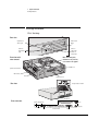
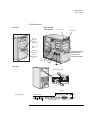
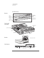
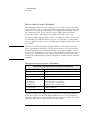
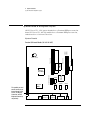
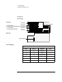
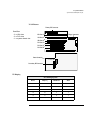
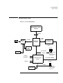
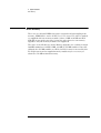
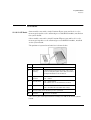
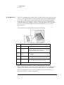
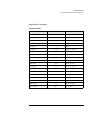
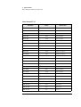
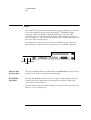
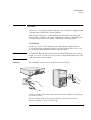
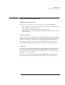
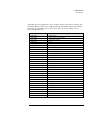
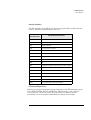
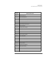
Technical Reference Manual
Product Description - Vectra VLi 8 & VLi 8SF
This technical reference and BIOS document for Vectra VLi 8 and VLi 8SF
PCs contains summary information only. More detailed information on
system hardware is available in the Technical Reference Manual Vectra Technology.
HP Vectra VLi 8 & VLi 8SF PCs
Contents
1 System Overview
Package Features. . . . . . . . . . . . . . . . . . . . . . . . . . . . . . . . . . . . . . . . . . 10
VLi 8 Desktop . . . . . . . . . . . . . . . . . . . . . . . . . . . . . . . . . . . . . . . . . . . . . .
VLi 8 Minitower . . . . . . . . . . . . . . . . . . . . . . . . . . . . . . . . . . . . . . . . . . . . .
VLi 8SF Desktop . . . . . . . . . . . . . . . . . . . . . . . . . . . . . . . . . . . . . . . . . . . .
10
11
12
Specifications. . . . . . . . . . . . . . . . . . . . . . . . . . . . . . . . . . . . . . . . . . . . . 13
Physical Characteristics . . . . . . . . . . . . . . . . . . . . . . . . . . . . . . . . . . . . . .
Electrical Specifications (All Models). . . . . . . . . . . . . . . . . . . . . . . . . . . .
Environmental Specifications (All Models) . . . . . . . . . . . . . . . . . . . . . . .
13
16
16
2 System Features
System Board & Backplane Layout. . . . . . . . . . . . . . . . . . . . . . . . . . . 18
System Boards . . . . . . . . . . . . . . . . . . . . . . . . . . . . . . . . . . . . . . . . . . . . . . 18
Pentium II/III-based Models (VLi 8 & VLi 8SF) . . . . . . . . . . . . . . . . . . . .18
Celeron-based Models (VLi 8SF only). . . . . . . . . . . . . . . . . . . . . . . . . . . .19
Backplane . . . . . . . . . . . . . . . . . . . . . . . . . . . . . . . . . . . . . . . . . . . . . . . . . . 20
VLi 8 Desktop . . . . . . . . . . . . . . . . . . . . . . . . . . . . . . . . . . . . . . . . . . . . . . .20
VLi 8 Minitower. . . . . . . . . . . . . . . . . . . . . . . . . . . . . . . . . . . . . . . . . . . . . .21
VLi 8SF Desktop . . . . . . . . . . . . . . . . . . . . . . . . . . . . . . . . . . . . . . . . . . . . .22
Architectural View. . . . . . . . . . . . . . . . . . . . . . . . . . . . . . . . . . . . . . . . . 23
All VLi 8 & VLi 8SF Models . . . . . . . . . . . . . . . . . . . . . . . . . . . . . . . . . . . .
23
Main Memory . . . . . . . . . . . . . . . . . . . . . . . . . . . . . . . . . . . . . . . . . . . . . 24
Processors . . . . . . . . . . . . . . . . . . . . . . . . . . . . . . . . . . . . . . . . . . . . . . . 25
Mass Storage Devices . . . . . . . . . . . . . . . . . . . . . . . . . . . . . . . . . . . . . . 27
Hard Disk Drives . . . . . . . . . . . . . . . . . . . . . . . . . . . . . . . . . . . . . . . . . . . .
Floppy Disk Drives. . . . . . . . . . . . . . . . . . . . . . . . . . . . . . . . . . . . . . . . . . .
CD-ROM and DVD Drives . . . . . . . . . . . . . . . . . . . . . . . . . . . . . . . . . . . . .
27
27
28
English iii
VLi 8 Models. . . . . . . . . . . . . . . . . . . . . . . . . . . . . . . . . . . . . . . . . . . . . . . . 28
DVD Region Codes. . . . . . . . . . . . . . . . . . . . . . . . . . . . . . . . . . . . . . . . . . . 29
VLi 8SF Models . . . . . . . . . . . . . . . . . . . . . . . . . . . . . . . . . . . . . . . . . . . . . 30
Matrox Millennium G200 AGP 2X Graphics Chip . . . . . . . . . . . . . .
32
Features . . . . . . . . . . . . . . . . . . . . . . . . . . . . . . . . . . . . . . . . . . . . . . . . . . . 32
Video Memory . . . . . . . . . . . . . . . . . . . . . . . . . . . . . . . . . . . . . . . . . . . . . . 32
Supported Resolutions . . . . . . . . . . . . . . . . . . . . . . . . . . . . . . . . . . . . . . . 33
UNDER WINDOWS 95 . . . . . . . . . . . . . . . . . . . . . . . . . . . . . . . . . . . . . . . . . . 33
UNDER WINDOWS NT 4.0
Connectors. . . . . . . . . . . . . . . . . . . . . . . . . . . . . . . . . . . . . . . . . . . . . . . . . 34
Audio . . . . . . . . . . . . . . . . . . . . . . . . . . . . . . . . . . . . . . . . . . . . . . . . . . .
36
Network . . . . . . . . . . . . . . . . . . . . . . . . . . . . . . . . . . . . . . . . . . . . . . . .
37
VLi 8 Models . . . . . . . . . . . . . . . . . . . . . . . . . . . . . . . . . . . . . . . . . . . . . . .
VLi 8SF Models . . . . . . . . . . . . . . . . . . . . . . . . . . . . . . . . . . . . . . . . . . . . .
37
38
Accessory Boards. . . . . . . . . . . . . . . . . . . . . . . . . . . . . . . . . . . . . . . . .
39
3 Serviceability
VLi 8 Models . . . . . . . . . . . . . . . . . . . . . . . . . . . . . . . . . . . . . . . . . . . . .
42
VLi 8SF Models . . . . . . . . . . . . . . . . . . . . . . . . . . . . . . . . . . . . . . . . . . .
44
iv English
4 BIOS Overview
BIOS Summary. . . . . . . . . . . . . . . . . . . . . . . . . . . . . . . . . . . . . . . . . . . . 46
Using the HP Setup Program. . . . . . . . . . . . . . . . . . . . . . . . . . . . . . . . . . . 46
Main Menu. . . . . . . . . . . . . . . . . . . . . . . . . . . . . . . . . . . . . . . . . . . . . . . . . .47
Advanced Menu . . . . . . . . . . . . . . . . . . . . . . . . . . . . . . . . . . . . . . . . . . . . .47
Security . . . . . . . . . . . . . . . . . . . . . . . . . . . . . . . . . . . . . . . . . . . . . . . . . . . .48
Boot Menu. . . . . . . . . . . . . . . . . . . . . . . . . . . . . . . . . . . . . . . . . . . . . . . . . .48
Power Menu . . . . . . . . . . . . . . . . . . . . . . . . . . . . . . . . . . . . . . . . . . . . . . . .48
Power Saving and Ergonometry . . . . . . . . . . . . . . . . . . . . . . . . . . . . . 49
Power-On from Space-Bar. . . . . . . . . . . . . . . . . . . . . . . . . . . . . . . . . . . . .
Soft Power Down . . . . . . . . . . . . . . . . . . . . . . . . . . . . . . . . . . . . . . . . . . . .
Safe Off . . . . . . . . . . . . . . . . . . . . . . . . . . . . . . . . . . . . . . . . . . . . . . . . . . . .
49
49
49
BIOS Addresses . . . . . . . . . . . . . . . . . . . . . . . . . . . . . . . . . . . . . . . . . . . 50
System Memory Map . . . . . . . . . . . . . . . . . . . . . . . . . . . . . . . . . . . . . . . . . 50
HP I/O Port Map (I/O Addresses Used by the System) . . . . . . . . . . . . . . 50
DMA Channel Controllers . . . . . . . . . . . . . . . . . . . . . . . . . . . . . . . . . . . . .52
Interrupt Controllers . . . . . . . . . . . . . . . . . . . . . . . . . . . . . . . . . . . . . . . . .53
PCI Interrupt Request Lines . . . . . . . . . . . . . . . . . . . . . . . . . . . . . . . . . . .53
Order in Which the POST Tests are Performed . . . . . . . . . . . . . . . . . 54
Beep Codes. . . . . . . . . . . . . . . . . . . . . . . . . . . . . . . . . . . . . . . . . . . . . . . 61
5 Drivers and Software
Drivers. . . . . . . . . . . . . . . . . . . . . . . . . . . . . . . . . . . . . . . . . . . . . . . . . . . 64
Software . . . . . . . . . . . . . . . . . . . . . . . . . . . . . . . . . . . . . . . . . . . . . . . . . 64
BIOS Updates . . . . . . . . . . . . . . . . . . . . . . . . . . . . . . . . . . . . . . . . . . . . . 65
English v
vi English
About this Document
About this Document
This technical reference and BIOS document for Vectra VLi 8 and VLi 8SF
PCs contains summary information only. More detailed information on
system hardware is available in the Technical Reference Manual - Vectra
Technology.
VLi 8 & VLi 8SF Bibliography
❒ HP Vectra VLi 8 (D7940-90001) & VLi 8SF (D7820-90001) User’s Guides
manual
HP Vectra VLi 8 (D7940-UPG-ABA) & VLi 8SF (D7820-UPG-ABA)
Troubleshooting and Upgrade Guide manual at:
www.hp.com/go/vectrasupport
❒ Technical Reference Manual -Vectra Technology
www.hp.com/go/vectrasupport
❒ HP Vectra PC Service Handbook - 14th edition (to be published).
❒ HP Support Assistant CD-ROM (by subscription).
Data sheets can be obtained at:
❒ Pentium Processors
www.intel.com/design/pentiumII/datashts
www.intel.com/design/pentiumII/datashts
❒ Celeron Processors
www.intel.com/design/celeron/datashts
❒ Product Data Sheet
www.hp.com/vectra
7
VLi 8 & VLi 8SF Bibliography
8
1
System Overview
This chapter introduces the internal and external features, and lists the
specifications of the HP Vectra VLi 8 and VLi 8SF PC models.
1 System Overview
Package Features
Package Features
VLi 8 Desktop
Front view
Keyboard Lock
Status Light
Power On/Off
Button
Power on
Status Light
(flashes in
sleep mode)
Hard Disk
Drive Activity
Light
Front view with
cover removed
Note. An airflow guide,
installed over the processor,
is not shown in this graphic.
CD-ROM drive
System board switches
Main memory
Processor
Floppy disk drive
Rear view
Voltage selection Switch
Parallel Port
Rear connectors
Mouse
Speaker Microphone
Line In
10
USB
A
B
Serial Ports A & B
Keyboard
Display
1 System Overview
Package Features
VLi 8 Minitower
Front view with
cover removed
Front view
Floppy disk drive
CD-ROM drive
Power on
Status Light
(flashes in
sleep mode)
Power On/Off
Button
Keyboard Lock
Status Light
Note. An airflow guide,
installed over the
processor, is not
shown in this graphic.
Hard Disk
Drive Activity
Light
System board switches
Processor
Main memory
Rear view
Voltage selection Switch
Parallel Port
Rear connectors
Speaker Microphone
Line In
(some models)
A
B
USB
Serial Port A & B
Mouse
Keyboard
Display
11
1 System Overview
Package Features
VLi 8SF Desktop
Front view
Hard Disk
Drive Activity
Light
Power on
Status Light
(flashes in
sleep mode)
Keyboard Lock
Status Light
Power On/Off
Button
Front view with
cover removed
Floppy disk drive
System board switches
Processor
Main memory
CD-ROM drive
Rear view
Voltage selection Switch
Parallel Port
Rear Connectors
Mouse
Speaker Microphone
Line In
12
USB
A
B
Serial Ports A & B
Keyboard
Display
1 System Overview
Specifications
Specifications
Physical Characteristics
VLi 8 Desktop
Characteristic
Description
Weight
(excluding display and keyboard)
10.4 kg (22.9 pounds)
Dimensions
Width: 44.3cm (17.4 inches)
Height: 13.8cm (5.4 inches)
Depth: 43.5cm (17.1 inches)
Footprint
0.193 m2 (2.07 ft.2)
HP Windows 95 Keyboard
18.3 (W) by 7 inches (D) by 1.3 inches (H), when flat, or
18.3 (W) by 7 inches (D) by 2 inches (H), when standing
(46.4 cm x 17.8 cm x 3.3 cm [5.1 cm])
Power Supply
Input voltage: 100 - 127 V 6.0A, 200 - 240 V 3.0A ac
(voltage selection switch)
Input frequency: 50/60 Hz
Maximum output power: 200 W continuous
Power Consumption
Processor: 30 W
Video: 10 - 15 W
Hard Disk Drive: 12 W (typical)
CD-ROM Drive: 15.6 W
PCI accessory slots: up to 25 W per slot
ISA accessory slots: 10 W (max. per slot)
13
1 System Overview
Specifications
VLi 8 Minitower
Characteristic
14
Description
Weight
(excluding display and keyboard)
14.8 kg (32.6 pounds)
Dimensions
Width: 20.7cm (8.1 inches)
Height: 46.9cm (18.5 inches)
Depth: 45.5cm (17.9 inches)
Footprint
0.094 m2 (1.01 ft.2)
HP Windows 95 Keyboard
18.3 (W) by 7 inches (D) by 1.3 inches (H), when flat, or
18.3 (W) by 7 inches (D) by 2 inches (H), when standing
(46.4 cm x 17.8 cm x 3.3 cm [5.1 cm])
Power Supply
Input voltage: 100 - 127 V 6.0A, 200 - 240 V 3.0A ac
(voltage selection switch)
Input frequency: 50/60 Hz
Maximum output power: 200 W continuous
Power Consumption
Processor: 30 W
Video: 10 - 15 W
Hard Disk Drive: 12 W (typical)
CD-ROM Drive: 15.6 W
PCI accessory slots: up to 25 W per slot
ISA accessory slots: 10 W (max. per slot)
1 System Overview
Specifications
VLi 8SF Desktop
Characteristic
Description
Weight
(excluding display and keyboard)
7.54 kg (16.5 pounds)
Dimensions
Width: 37 cm (14.6 inches)
Height: 9.5 cm (3.7 inches)
Depth: 39 cm (15.4 inches)
Footprint
0.144 m2 (1.68 ft.2)
HP Windows 95 Keyboard
18.3 (W) by 7 inches (D) by 1.3 inches (H), when flat, or
18.3 (W) by 7 inches (D) by 2 inches (H), when standing
(46.4 cm x 17.8 cm x 3.3 cm [5.1 cm])
Power Supply
Input voltage: 100 - 127 V 6.0A, 200 - 240 V 3.0A ac
(voltage selection switch)
Input frequency: 50/60 Hz
Maximum output power: 90 W continuous
Power Consumption
Processor: 30 W
Video: 10 - 15 W
Hard Disk Drive: 12 W (typical)
CD-ROM Drive: 6 W
PCI accessory slots: up to 25 W per slot
ISA accessory slots: 10 W (max. per slot)
15
1 System Overview
Specifications
Electrical Specifications (All Models)
Any attempt to draw too much current (such as a short circuit across edgeconnector pins, or an accessory board that is not suitable for these PCs), will
cause the overload protection in the power supply to be triggered, and the
PC could fail to boot. To get out of the power supply protection mode,
remove the power cord, wait for 10 seconds, then replace the cord.
The power supply delivers 720mA at the V standby level. This extra current
is required by the 100TX hardware layer so it can perform a remote poweron at reception of a magic frame. An older power supply should not be used
for a repair.
NOTE
When the PC is turned off with the power button on the front panel, the
power consumption falls below 5 Watts, but is not zero. The special on/off
method used by this PC extends the lifetime of the power supply. To reach
zero power consumption in “off” mode, either unplug the PC from the power
outlet or use a power block with a switch. If the PC is turned off, the time
settings are maintained by the battery indefinitely (until the battery runs out
of power).
Environmental Specifications (All Models)
Environmental Specifications (System Processing Unit, with Hard Disk)
Operating Temperature
+10°C to +35°C (+ 50°F to 95° F)
Storage Temperature
-40°F to +70°F (-40°C to +158°C)
Operating Humidity
15% to 80% (relative)
Storage Humidity
8% to 85% (relative), non-condensing at 40°C (104°F)
Acoustic noise emission:
VLi 8 Desktop
VLi 8 Minitower
VLi 8SF Desktop
(as defined ISO 7779)
Sound level (LwA) ≤ 37 db (operating)
Sound level (LwA) ≤ 37 db (operating)
Sound level (LwA) ≤ 35.5 db (operating)
Operating Altitude
10000 ft (3100m) max
Storage Altitude
15000ft (4600m) max
Operating temperature and humidity ranges may vary depending upon the
mass storage devices installed. High humidity levels can cause improper
operation of disk drives. Low humidity levels can aggravate static electricity
problems and cause excessive wear of the disk surface.
16
2
System Features
This chapter describes core components of the PC such as processors,
chipsets, mass storage devices, graphics controllers, audio controllers,
network features and input devices.
2 System Features
System Board & Backplane Layout
System Board & Backplane Layout
All HP Vectra VLi 8 PC system boards have a Pentium II/III processor slot.
Some HP Vectra VLi 8SF PC models have a Pentium II/III processor slot,
and others have a Celeron 370 socket.
System Boards
DIMM1
DIMM2
Pentium II/III-based Models (VLi 8 & VLi 8SF)
Memory Slots
440 ZX
Processor Slot
Battery Socket
Crystal
Audio
The parallel port and
mouse connector are
located above Serial
Port A, the Display
Connector and the
Keyboard Connector,
respectively.
USB
18
Serial
Connector B
SDRAM
SDRAM
Serial
Connector A
Video Chip
System Board Switches
Intel PCI
Set PIIX4e
SDRAM
SDRAM
Display
Kbd
2 System Features
System Board & Backplane Layout
USB
Serial
Connector B
SDRAM
SDRAM
Serial
Connector A
Video Chip
System Board Switches
Intel PCI
Set
PIIX4e
Crystal
Audio
Memory Slots
Processor Socket
440 ZX
Battery Socket
The parallel port and
mouse connector are
located above Serial
Port A, the Display
Connector and the
Keyboard Connector,
respectively.
DIMM1
DIMM2
Celeron-based Models (VLi 8SF only)
SDRAM
SDRAM
Display
Kbd
19
2 System Features
System Board & Backplane Layout
Backplane
VLi 8 Desktop
Front View
IDE Connectors
PCI Slot #2
PCI Slot #3
- 2 ✕ PCI slots
- 1 PCI/ISA Combination slot PCI Slot #4/
ISA Slot #1
- 1 ✕ ISA slots
- 1 ✕ system board slot
ISA Slot #2
Floppy Connectors
}
Back View
Power Connector
VLi 8 PCI Mapping
VLi 8 PCI Mapping Table
20
Device
#AD[xx]
PCI Device
Slot#
0
11
440ZX PAC
4
15
PIIX4E
6
17
Integrated Audio
1
18
29
J1
2
16
27
J4
3
14
25
J8
4
2 System Features
System Board & Backplane Layout
VLi 8 Minitower
Primary IDE Connector
Front View
Floppy Connectors
ISA Slot #1
- 3 ✕ ISA slots
- 3 ✕ PCI slots
- 1 ✕ system board slot
ISA Slot #2
ISA Slot #3
PCI Slot #2
PCI Slot #3
PCI Slot #4
Power Connector
Secondary IDE Connector
PCI Mapping
VLi 8 PCI Mapping Table
Device
#AD[xx]
PCI Device
Slot#
0
11
440ZX PAC
4
15
PIIX4E
6
17
Integrated Audio
1
18
29
J1
2
16
27
J4
3
14
25
J8
4
21
2 System Features
System Board & Backplane Layout
VLi 8SF Desktop
Status Panel Connector
3COM 40-0483-004 Chip
Front view
- 1 ✕ PCI slot
- 1 ✕ ISA/PCI
combination slot
- 1 ✕ system board
slot
Fan Connector
PCI Slot #2
PCI Slot #3/
ISA Slot #1
}
Slim CD-ROM Connector
Back view
Power Connector
Primary IDE
Connector
Floppy Connector
PCI Mapping
VLi 8SF PCI Mapping Table (Celeron)
22
Device
#AD[xx]
PCI Device
Slot#
0
11
440ZX PAC
4
15
PIIX4E
6
17
Integrated Audio
1
18
29
J1
2
16
27
J4
3
11
22
Integrated LAN
4
2 System Features
Architectural View
Architectural View
All VLi 8 & VLi 8SF Models
Pentium II/III or Celeron
Processor
Host Bus
Graphics
Device
66/100
MHz
2X AGP Bus
B2443 ZX
Main Memory
Host Bridge
Display
3.3V EDO & SDRAM
Support
Graphics
Local
Memory
PCI Slots
Primary PCI Bus
Video BIOS
- 3 PCI slots are available
on VLi 8 models
- 2 PCI slots are available
on VLi 8SF models
PCI Bus #0
2 IDE Ports
Ultra DMA/33
PCI/ISA Bridge (PIIX4E)
82371EB
System MGMT (5MB)BUS
2 USB Ports
ISA Slots
ISA Bus
System BIOS
- 2 or 3 ISA slots are
available on VLi 8 models
- 1 ISA slot is available
on VLi 8SF models
23
2 System Features
Main Memory
Main Memory
There are two 168-pin DIMM slots on the system board for installing main
memory; DIMM slots 1 and 2. All HP Vectra VLi 8 and VLi 8SF PC models
are supplied with one memory module (either 32 MB or 64 MB non-ECC
SDRAM) in one of the two slots, leaving the other slots free for memory
upgrades. Only HP memory modules are supported.
The slots can be filled in any order. Memory upgrades are available in single
100 MHz modules of 32 MB, 64 MB, 128 MB or 256 MB modules. Note that
although the 256 MB modules are ECC, the ECC feature is not used by this
PC. Replacement of the supplied memory module may be necessary to
obtain the 512 MB maximum memory.
24
2 System Features
Processors
Processors
VLi 8 & VLi 8SF Models Some models come with a single Pentium II processor and level-2 cache
memory packaged in a self-contained, pre-sealed SECC2 module, installed on
the system board.
Other models come with a single Pentium III processor and level-2 cache
memory packaged in a self-contained, pre-sealed SECC2 module, installed
on the system board.
The position of system board switches is shown below:
Switch
Switch function:
1
Reserved
Do not use - OFF (default)
2
BIOS Crisis
Recovery
Should normally be kept in the OFF position. Used in case of
power loss during BIOS update. Refer to flash.txt in the BIOS
package downloadable from the HP Web site.
3
Keyboard
power-on:
ON = enabled (default)
OFF = disabled
4
Clear Password:
OFF = disabled (default)
ON= enabled / clear User and Administrator passwords
5
Clear CMOS:
OFF = normal (default)
ON = clear CMOS and reload default values in Setup
6- 9
Processor speed, refer to the table on your PC’s system board.
10
Reserved
Do not use - OFF (default)
The correct processor speed switch settings are indicated on the system
board.
25
2 System Features
Processors
VLi 8SF Models Only
The PC is equipped with a single Socket 370 Intel Celeron processor. Socket
370 is a conversion of Slot 1 (used previously by Celerons and Pentium IIs)
to a socket, running at the same bus protocol as the Pentium II (the GTL+
bus protocol). The processor is connected to the system board through a
Plastic Pin Grid Array (PPGA) 370 Socket. The reduction in size achieved by
the Socket 370 Celeron is due to the integration of the L2 cache on the
processor die.
The position of system board switches is shown below:
Switch
Switch function:
1
Reserved
Do not use - OFF (default)
2
BIOS Crisis
Recovery
Should normally be kept in the OFF position. Used in case of
power loss during BIOS update. Refer to flash.txt in the BIOS
package downloadable from the HP Web site.
3
Keyboard
power-on:
ON = enabled (default)
OFF = disabled
4
Clear Password:
OFF = disabled (default)
ON= enabled / clear User and Administrator passwords
5
Clear CMOS:
OFF = normal (default)
ON = clear CMOS and reload default values in Setup
6- 9
Processor speed, refer to the table on your PC’s system board.
Even though the Celeron processor’s speed settings are automatic,
HP recommends that you set the system board switches to the appropriate
settings. The correct switch settings are indicated on the system board.
For more information on processor technology, refer to the Technical
Reference Manual - Vectra Technology.
26
2 System Features
Mass Storage Devices
Mass Storage Devices
Hard Disk Drives
A 3.5-inch hard disk drive is supplied on an internal shelf in some models.
These hard drives can be provided with the PC. To see which other hard
disk drives can be purchased as accessories for the VLi 8 & VLi 8SF, refer to
www.hp.com/go/vectraaccessories.
4.3 GB
Ultra-ATA 33
8.4 GB
Ultra-ATA 33
6.4 GB
Ultra-ATA 33
13.5 GB
Ultra-ATA 33
Availability
VLi 8SF
VLi 8, VLi 8SF
VLi 8 models only
VLi 8 models only
Average seek write time
11.0 ms
11.0 ms
11.0 ms
-
Average seek read time
9.5 ms
9.5 ms
9.5 ms
9 ms
Revolutions per minute (RPM)
5400
5400
5400
7200
Average Latency
5.6 ms
5.6 ms
5.6 ms
4.18 ms
Maximum external transfer rate
16.7/33 MB/s
16.7/33 MB/s
16.7/33 MB/s
16.7/33 MB/s
To find out about Ultra-ATA DMA/33 hard disk drive technology, refer to the
Technical Reference Manual - Vectra Technology.
Floppy Disk Drives
All models are supplied with a 3.5-inch floppy disk drive.
27
2 System Features
Mass Storage Devices
CD-ROM and DVD Drives
VLi 8 Models
Both the desktop and minitower models have a TEAC 32✕ Max IDE CDROM drive. It can play standard CD-ROM discs, conforming to optical and
mechanical standards as specified in the Red and Yellow Book. The DVD
Drive below can be purchased as an accessory. Refer to
www.hp.com/go/vectraaccessories.
To find out about CD-ROM and DVD drive technology, refer to Technical
Reference Manual - Vectra Technology.
Features of the
CD-ROM Drive
(D4384A)
•
•
•
•
•
•
CD-ROM Mode-1 data disc.
CD-ROM Mode-2 data disc (Mode 1 and Mode 2).
Photo-CD Multisession.
CD Audio disc.
Mixed mode CD-ROM disc (data and audio).
CD-ROM XA, CD-I, CD-Extra, CD-R, CD-RW.
Description
Hp product number
D4384A
Disc Diameter
120 mm
Data Block Size
2,055 bytes (14X, Mode-1)
4,800 bytes (32X, Mode-2)
Storage Capacity
650 Mbytes (Mode-1)
742 Mbytes (Mode-2)
Read Mode
Full CAV1 10.3X to 24X
Burst Transfer Rate
PIO mode 4 - 16.6 Mbytes/s maximum
Single Word DMA Mode 2 - 8.3 Mbytes/s maximum
Multi Word DMA Mode 2 - 16.6 Mbytes/s maximum.
Access Time
Average Stroke (1 / 3) 110 ms
Full Stroke 180 ms
Buffer Memory Size
128 kbytes
Rotational speed
Approx. 7,300 rpm maximum
1.CAV
28
= Constant Angular Velocity
2 System Features
Mass Storage Devices
Features of the
DVD-ROM Drive
(D6935A)
•
•
•
•
•
•
•
CD-ROM Mode-1 data disc.
CD-ROM Mode-2 data disc (Mode 1 and Mode 2).
Photo-CD Multisession.
CD Audio disc.
Mixed mode CD-ROM disc (data and audio).
CD-ROM XA, CD-I, CD-Extra, CD-R, CD-RW.
DVD-ROM, DVD-Video.
Description
HP product number
Disc Diameter
Storage Capacity
Read Mode
Burst Transfer Rate
D6935A
120 mm
650 MB to 17 GB (depending on disk type)
5 X max (DVD), 32X max CD-ROM
PIO mode 4 - 16.6 Mbytes/s maximum
Single Word DMA Mode 2 - 8.3 Mbytes/s maximum
Multi Word DMA Mode 2 - 16.6 Mbytes/s maximum.
Average Stroke (1 / 3) 110 ms
Full Stroke 180 ms
128 kbytes
Approx. 7,300 rpm maximum
Access Time
Buffer Memory Size
Rotational speed
NOTE
If a disk is still in the drive after power failure or drive failure, the disk can be
reclaimed by inserting a straightened paper-clip into the small hole at the
bottom of the door.
DVD Region Codes
The DVD-ROM drive is only able to play DVD video discs from regions 1 and
2 (see table below). Once a video disc has been played on the device, it will
then only be able to play video discs with the same region code.
Region Codes
Supported by the
D6935A DVD Drive
Region
1
USA & Canada
Yes
2
Europe & Japan
Yes
3
South East Asia
No
4
Latin America & Australia
No
5
Russia, Rest of Asia, Africa
No
6
China
No
29
2 System Features
Mass Storage Devices
VLi 8SF Models
The VLi 8SF models have a 24✕ Max Slim IDE CD-ROM drive. It can play
standard CD-ROM discs, conforming to optical and mechanical standards as
specified in the Red and Yellow Book.
Features of the
Slim CD-ROM Drive
(D8381A)
•
•
•
•
•
•
•
CD-ROM Mode-1 data disc.
CD-ROM Mode-2 data disc (Mode 1 and Mode 2).
Photo-CD Multisession.
Enhanced CD
CD Audio disc.
Mixed mode CD-ROM disc (data and audio).
CD-ROM XA, CD-I, CD-Extra, CD-R, CD-RW.
Description
HP product number
D8381A
Disc Diameter
120 mm
Data Block Size
2,055 bytes (14X, Mode-1)
4,800 bytes (32X, Mode-2)
Storage Capacity
650 Mbytes (Mode-1)
742 Mbytes (Mode-2)
Read Mode
Full CAV1 10.3X to 24X
Burst Transfer Rate
PIO mode 4 - 16.7 Mbytes/s maximum
Single Word DMA Mode 2 - 8.3 Mbytes/s maximum
Multi Word DMA Mode 2 - 16.7 Mbytes/s maximum.
Access Time
Average Stroke (1 / 3) 130 ms
Full Stroke 300 ms
Buffer Memory Size
128 kbytes
Rotational speed
Approx. 5,136 rpm on average
1.CAV
30
= Constant Angular Velocity
2 System Features
Mass Storage Devices
NOTE
The Slim CD-ROM drive’s draw is not motorized; a spring mechanism
operates the draw. To extract a CD-ROM, you will need to gently pull the
draw out until you are able to remove the disk.
If a disk is still in the drive after power failure or drive failure, the disk can be
reclaimed by inserting a straightened paper-clip into the small hole at the
bottom of the door.
Audio Connection
The Slim CD-ROM drive does not have a separate audio connection to the
system board. The audio signal is transmitted via the drive’s IDE cable
connection to the backplane.
31
2 System Features
Matrox Millennium G200 AGP 2X Graphics Chip
Matrox Millennium G200 AGP 2X Graphics Chip
All HP Vectra VLi 8 and VLi 8SF PC models are supplied with a Matrox
Millennium G200 AGP 2X graphics controller integrated in the system board
(refer to the system board diagram on page 18 for its location).
The Matrox Millennium G200 is aimed at business users who want highresolution support coupled with high performance.
For more information, refer to the Technical Reference Manual - Vectra
Technology available in PDF (Acrobat) format from www.hp.com/go/
vectrasupport
Features
• 128-bit DualBus graphics chip
• High-performance video with full AGP 2X support featuring Symmetrical
Rendering Architecture
• Advanced 2D, 3D and software DVD video acceleration
• High-quality 32-bit color 3D rendering engine
• 8MB of graphics memory, non-upgradeable
• High-speed 250 MHz RAMDAC with ultra sharp image quality. Provides
fast screen refresh to eliminate screen flicker.
• Support for high resolutions and colors
Video Memory
All HP Vectra VLi 8 and VLi 8SF PC models are supplied with 8 MB of
video memory (not upgradeable) integrated on the system board.
The video RAM (also known as the frame buffer) is a local block of 50 ns
SDRAM for holding both the on-screen surface (reflecting what is currently
displayed on the screen), and the off-screen surface (video frame, fonts,
double buffer).
32
2 System Features
Matrox Millennium G200 AGP 2X Graphics Chip
Supported Resolutions
UNDER WINDOWS 95
Resolution
Colors
Refresh rates
640 ✕ 480
16
60 Hz
640 ✕ 480
256
60, 72, 75, 85 Hz
640 ✕ 480
64 K
60, 72, 75, 85 Hz
640 ✕ 480
16 M
60, 72, 75, 85 Hz
800 ✕ 600
16
60 Hz
800 ✕ 600
256
56, 60, 72, 75, 85 Hz
800 ✕ 600
64 K
56, 60, 72, 75, 85 Hz
800 ✕ 600
16 M
56, 60, 72, 75, 85 Hz
1024 ✕ 768
256
60, 70, 75, 85 Hz
1024 ✕ 768
64 K
60, 70, 75, 85 Hz
1024 ✕ 768
16 M
60, 70, 75, 85 Hz
1152 ✕ 864
256
60, 70, 75, 85 Hz
1152 ✕ 864
64 K
60, 70, 75, 85 Hz
1152 ✕ 864
16 M
60, 70, 75, 85 Hz
1280 ✕ 1024
256
60, 75, 85 Hz
1280 ✕ 1024
64 K
60, 75, 85 Hz
1280 ✕ 1024
16 M
60, 75, 85 Hz
1600 ✕ 1200
256
60, 70, 75, 85 Hz
1600 ✕ 1200
64 K
60, 70, 75 Hz
33
2 System Features
Matrox Millennium G200 AGP 2X Graphics Chip
UNDER WINDOWS NT 4.0
Resolution
Colors
Refresh rates
640 ✕ 480
16
60 Hz
640 ✕ 480
256
60, 72, 75, 85 Hz
640 ✕ 480
32K
60, 72, 75, 85 Hz
640 ✕ 480
64 K
60, 72, 75, 85 Hz
640 ✕ 480
16 M
60, 72, 75, 85 Hz
800 ✕ 600
16
60 Hz
800 ✕ 600
256
56, 60, 72, 75, 85 Hz
800 ✕ 600
32 K
56, 60, 72, 75, 85 Hz
800 ✕ 600
64 K
56, 60, 72, 75, 85 Hz
800 ✕ 600
16 M
56, 60, 72, 75, 85 Hz
1024 ✕ 768
256
i43, 60, 70, 75, 85 Hz
1024 ✕ 768
32 K
i43, 60, 70, 75, 85 Hz
1024 ✕ 768
64 K
i43, 60, 70, 75, 85 Hz
1024 ✕ 768
16 M
i43, 60, 70, 75, 85 Hz
1152 ✕ 864
256
60, 70, 75, 85 Hz
1152 ✕ 864
32 K
60, 70, 75, 85 Hz
1152 ✕ 864
64 K
60, 70, 75, 85 Hz
1152 ✕ 864
16 M
60, 70, 75, 85 Hz
1280 ✕ 1024
256
60, 75, 85 Hz
1280 ✕ 1024
32 K
60, 75, 85 Hz
1280 ✕ 1024
64 K
60, 75, 85 Hz
1280 ✕ 1024
16 M
60, 75, 85 Hz
1600 ✕ 1200
256
60, 75, 85 Hz
1600 ✕ 1200
32 K
60, 75, 75 Hz
1600 ✕ 1200
64 K
60, 75 Hz
34
2 System Features
Matrox Millennium G200 AGP 2X Graphics Chip
Connectors
A 15-pin VGA DB connector is located on the rear panel of all VLi 8
and VLi 8SF PCs (refer to the system board diagrams on page 18 for its
location).
15-pin VGA DB Connector
35
2 System Features
Audio
Audio
The Crystal® integrated PCI audio solution (not upgradeable) in your PC is
a two-chip solution made up of the CrystalClear™ CS4280 PCI audio
controller and the CrystalClear CS4297 Audio Codec ‘97. The audio
controller interfaces with the PCI bus and performs all digital operations
such as sample rate conversions and synthesis. The CS4297 chip mixes and
processes all the analog signals.
All models have a Line In jack, Line Out jack and Mic In jack connector
located on the rear panel. These external jacks are standard connectors.
Speaker Microphone
Line In
Adding an Audio
Accessory Board
The integrated PCI audio can be disabled in the Advanced menu of the Setup
program, if an audio accessory board is installed.
Slim CD-ROM’s
Audio Signal
The Slim CD-ROM drive does not have a separate audio connection to the
system board. The audio signal is transmitted via the drive’s IDE cable
connection to the backplane.
For more information on audio technology, refer to the Technical Reference
Manual - Vectra Technology.
36
2 System Features
Network
Network
All HP Vectra VLi 8SF PC models and some VLi 8 models are supplied with
a 10/100 3Com 3C905B-TX network solution.
This network solution is a 32-bit PCI Ethernet Controller with advanced
manageability capabilities. It features full-duplex, automatic 10/100 BT port
selection, Remote Power-On (RPU), and Remote Wake-Up (RWU).
VLi 8 Models
On HP Vectra VLi 8 PC models, the network solution is deployed as an
accessory board (part number D7506A), installed in PCI slot #3. The card
has an optional Boot ROM for diskless node operation.
NOTE
A 3COM LAN Boot ROM is integrated in the BIOS ROM chip on the system
board. As a result, it is not necessary to insert a Boot ROM chip into the LAN
card to perform a Remote Boot.
Connectors
The 10/100BT connector is located on the rear of the PC.
A Wake On LAN (WOL) connector is located on the backplane (refer to page
23 for its location).
For more information on network technology, refer to the Technical
Reference Manual - Vectra Technology.
37
2 System Features
Network
VLi 8SF Models
On HP Vectra VLi 8SF PC models, the network solution is integrated; the
3COM chip is built into the backplane (refer to backplane diagram on page
22 for its location).
Connectors
The 10/100BT connector and a network activity indicator are located on the
rear panel of the PC.
When connected, the activity indicator glows constantly. The indicator will
blink to indicate network activity.
There is no Wake On LAN (WOL) connector.
Adding a Network
Accessory Board
The integrated network can be disabled in the Advanced menu of the Setup
program, if a network accessory board is installed. However, as there is no
Wake On LAN (WOL) connector, this feature is lost when a network
accessory board is installed.
NOTE
A 3COM LAN Boot ROM is integrated in the BIOS ROM chip on the system
board. As a result, it is not necessary to insert a Boot ROM chip into the LAN
card to perform a Remote Boot.
For more information on network technology, refer to the Technical
Reference Manual - Vectra Technology.
38
2 System Features
Accessory Boards
Accessory Boards
Your PC uses logical slot numbers in the BIOS Setup program. You need to
know these logical slot numbers if you want to change the PCI slot
configuration in the Setup program (refer to the appropriate backplane
diagrams on page 20 for their location).
VLi 8 Desktop
This model has four accessory board slots. Two PCI slots, one PCI/ISA
combination slot and one ISA slot (refer to the backplane diagram on page 21
for their location).
• PCI slots #2, #3 and #4 can be used for full-length 32-bit PCI boards.
• ISA slots #1 and #2 can be used for full-length 16-bit ISA boards.
This model comes preloaded with a 3COM Network card installed in PCI
slot #3.
VLi 8 Minitower
This model has six accessory board slots. Three PCI slots and three ISA board
slots (refer to the backplane diagram on page 20 for their location).
• PCI slots #2, #3 and #4 can be used for full-length 32-bit PCI boards.
• ISA slots #1, #2 and 3# can be used for full-length XT format 16-bit ISA
boards.
This model comes preloaded with a 3COM Network card in installed PCI
slot #3.
VLi 8SF Desktop
This model has two accessory board slots. One PCI slot and one PCI/ISA
combination slot (refer to the backplane diagram on page 22 for their
location).
• PCI slots #2 and #3 can be used for 32-bit XT format PCI boards, less than
17.6 cm or 6.9-inches in length.
• ISA slot #1 can be used for a 16-bit half-length XT format ISA board.
NOTE
For a list of accessory boards that can be purchased as accessories for your
PC, refer to www.hp.com/go/vectraaccessories.
39
2 System Features
Accessory Boards
40
3
Serviceability
This chapter introduces the enhanced serviceability features of the
HP Vectra VLi 8 and VLi 8SF PC models. It indicates how to quickly
remove or add system components using the serviceability features
developed for these PC models.
3 Serviceability
VLi 8 Models
VLi 8 Models
Desktop
Shows how to remove
the system board
Shows how to remove
the hard disk drive
Shows how to add an
accessory board
Shows how to remove
the floppy drive
Shows how to remove
the front drive bay
Note. Step 1 does not apply to VLi 8 PC models.
42
3 Serviceability
VLi 8 Models
Minitower
Shows how to remove
the hard disk drive
Shows how to remove the system board
Shows how to remove
the CD-ROM drive
Note. Step 2 does not apply to VLi 8 PC models.
43
3 Serviceability
VLi 8SF Models
VLi 8SF Models
Shows how to remove
the side panel
Shows how to remove
the hard disk, floppy disk
and CD-ROM drives
Shows how to add an
accessory boars
Shows how to remove
the system board
44
Shows how to remove the power and
data cables before removing a hard
disk, floppy disk and CD-ROM drive
4
BIOS Overview
This chapter describes the BIOS features for the HP Vectra VLi 8
and VLi 8SF PC models.
4 BIOS Overview
BIOS Summary
BIOS Summary
HP Vectra VLi 8 and VLi 8SF PCs contain an HP/Phoenix BIOS (Basic Input
Output System). The system ROM contains the POST (power-on self-test)
routines, and the BIOS: the System BIOS, video BIOS, and low
option ROM.
The system BIOS is identified by the version number HZ.01.xx. The latest
BIOS version for your PC and instructions for updating the BIOS can be
downloaded from the HP’s Support Web site at:
www.hp.com/go/vectrasupport.
This section covers:
•
•
•
•
•
The BIOS Setup program
Power saving
BIOS addresses
The order in which POST tests are performed
Beep codes.
Using the HP Setup Program
Press F2 to run the Setup program, when the “Vectra” logo is displayed
immediately after restarting the PC.
Press F8 to enter the Boot menu. Use the boot menu to select the order of the
devices the PC will use to start (boot) from.
Alternatively, press Esc to view the summary configuration screen. By default,
this remains on the screen for 20 seconds, but by pressing the Pause key
once, it can be held on the screen indefinitely until F1 is pressed again.
Pressing F10 will cause the computer to be turned off.
The Setup screen offers five menus: Main, Advanced, Security, Boot, Power
and Exit. These are selected using the left and right arrow keys.
46
4 BIOS Overview
BIOS Summary
Main Menu
The Main Menu contains the following fields:
•
•
•
•
•
•
•
•
•
•
•
PnP Operating System
Reset Configuration Data
PS/2 Mouse
System time and date
Key click
Key Auto-repeat Speed
Processor serial number
Standard Applications (set to YES by default)1
Delay Before Auto-repeat
Numlock at Power-On
Boot-time Diagnostics Screen.
1. This field should be set to YES if all applications you are using are Year 2000 compliant.
Advanced Menu
The Advanced Menu does not have the same structure as the Main Menu and
Power Menu. Instead of presenting a list of fields, it offers a list of
sub-menus. The Advanced Menu contains the following sub-menus:
• Memory and Cache. Define how to configure the specified block of
memory.
• Floppy Disk Drives. Enable or disable the on-board floppy disk
controller.
• IDE Devices. Configure IDE Primary and Secondary devices.
• Integrated I/O Ports. Enable or disable the on-board parallel and
serial ports at the specified address.
• Integrated USB Interface. Enable or disable the integrated USB
(Universal Serial Bus) interface.
• PCI Configuration.
• PCI Device. Use this option if you want to configure (enable/disable
Option ROM Scan and Enable Master) PCI device.
• Integrated Network Interface. Enable or disable the integrated
VLi 8SF models only
network interface. This feature must be enabled when an ethernet
card is installed.
• ISA Resource Exclusion. reserves interrupts for legacy ISA devices to
prevent conflict with PCI/PnP devices.
• Integrated Audio Interface. Enable or disable the integrated PCI Audio
interface. This feature must be disabled if an accessory board is installed.
47
4 BIOS Overview
BIOS Summary
Security
Sub-menus are presented for changing the characteristic and values of the
System Administrator Password, User Password, Hardware Protection and
Boot Device Security, the amount of protection against the system’s drives and
network connections, and the amount of protection against being able to boot
from the system’s drives and network connections. The Security Menu
contains the following sub-menus:
• User Password. This password can only be set when an administrator
password has been set. The User Password prevents unauthorized use of
the computer, protects stored data.
• Administrator Password. This password prevents unauthorized access
to the computer’s configuration. It can also be used to start the computer.
• Hardware Protection. The following devices can have their accesses
unlocked/locked: Integrated Floppy Disk Controller, Integrated IDE
Controller, and Integrated Data Communications Ports.
• Boot Device Security. Select which devices are to be used for booting up
the system. The option Disabled prevents unauthorized use of a device to
start the computer.
Boot Menu
Select the order of the devices from which the BIOS attempts to boot the
operating system. During POST, if the BIOS is unsuccessful at booting from
one device, it will then try the next one on the Boot Device Priority list until
an operating system is found.
The QuickBoot Mode option allows the system to skip certain tests while
booting. This decreases the time needed to boot the system.
The Boot-time Diagnostics screen enables the user to display either the
Vectra logo or diagnostic’s screen during POST.
Power Menu
This menu allows you to set the Suspend and Standby delays. It enables the
user to decide if an IRQ can reactivate the system when in suspend mode. It
also allows the system administrator to decide whether the network interface
is enabled as a means of reactivating the system from Suspend
or Off.
48
4 BIOS Overview
Power Saving and Ergonometry
Power Saving and Ergonometry
Power-On from Space-Bar
The Power-on from the space-bar function is enabled, provided that:
• The computer is connected to a Power-On keyboard (recognizable by the
Power-On icon on the space bar).
• The computer is running a Windows operating system.
• The function has not been disabled by setting SW-3 to open on the system
board switches.
Soft Power Down
Soft Power Down is available with the Windows NT operating system. If users
want to shut down their PC, they are able to do so directly from the Windows
NT interface. There is no longer any need to physically switch off the PC.
The hardware to do this is contained in the PIIX4E chipset. This chipset is
described in detail in Technical Reference Manual - Vectra Technology.
Safe Off
Safe Off is available with the Windows 95 and Windows 98 operating systems.
If users attempt to shut down the operating system when an application is
open and has not been saved, they are requested to save their work before the
computer can be powered off.
The hardware to do this is contained in the PIIX4E chipset. This chipset is
described in detail in Technical Reference Manual - Vectra Technology.
49
4 BIOS Overview
BIOS Addresses
BIOS Addresses
This section provides a summary of the main features of the HP system BIOS.
This is software that provides an interface between the computer hardware
and the operating system.
System Memory Map
Reserved memory used by accessory boards must be located in the area from
C8000h to EFFFFh.
0000 0000 - 0000 03FF
Real-mode IDT
0000 0400 - 0000 04FF
BIOS Data Area
0000 0500 - 0009 FC00
Used by OS
0009 FC00 - 0009 FFFF
Extended BIOS Data Area
000A_0000 - 000B_FFFF
Video RAM or
SMRAM (not visible unless in SMM)
000C 0000 - 000C 7FFF
Video ROM
000C 8000 - 000F FFFF
Adapter ROM, RAM, memory-mapped registers
000E 0000 - 000F FFFF
System BIOS (Flash/Shadow)1
10 0000 - FF FFFF
Memory (1 MB to 16 MB)
100 0000 - 1FF FFFF
Memory (16 MB to 32 MB)
200 0000 -3FF FFFF
Memory (32 MB to 64 MB)
400 0000 -1FFF FFFF
Memory (64 MB to 512 MB)
FFFC0000 - FFFF FFFF
256 KB BIOS (Flash)
1.
This is for Physical memory. As soon as the PST has been
completed, the E0000-E8000 segment is released for UMBs.
HP I/O Port Map (I/O Addresses Used by the System1)
Peripheral devices, accessory devices and system controllers are accessed via
the system I/O space, which is not located in system memory space. The 64 KB
of addressable I/O space comprises 8-bit and 16-bit registers (called
I/O ports) located in the various system components. When installing an
accessory board, ensure that the I/O address space selected is in the free area
of the space reserved for accessory boards (100h to 3FFh).
1.
50
If configured.
4 BIOS Overview
BIOS Addresses
Although the Setup program can be used to change some of the settings, the
following address map is not completely BIOS dependent, but is determined
partly by the operating system. Note that some of the I/O addresses are
allocated dynamically.
I/O Address Ports
0000 - 000F
0020 - 0021
002E - 002F
0040 - 0043
0060, 0064
0061
0070
0070 - 0071
0080
0081 - 0083, 008F
0092
00A0 - 00A1
00C0 - 00DF
00F0 - 00FF
0170 - 0177
01F0 - 01F7
0278 - 027F
02E8 - 02EF
02F8 - 02FF
0372 - 0377
0378 - 037A
03B0 - 03DF
03E8 - 03EF
03F0h- 03F5
03F6
03F7
03F8 - 03FF
04D0 - 04D1
0678 - 067B
0778 - 077B
0CF8 - 0CFF
Function
DMA controller 1
Master interrupt controller (8259)
Configuration registers
Timer 1
Keyboard controller (reset, slow A20)
Port B (speaker, NMI status and control)
Bit 7: NMI mask register
RTC and CMOS data
Manufacturing port (POST card)
DMA low page register
PS/2 reset and Fast A20
Slave interrupt controller
DMA controller 2
Co-processor error
IDE secondary channel
IDE primary channel
LPT 2
Serial port 4 (COM4)
Serial port 2 (COM2)
IDE secondary channel, secondary floppy disk drive
LPT1
VGA
COM3
Floppy disk drive controller
IDE primary channel
Floppy disk drive controller
COM1
Interrupt edge/level control
LPT2 ECP
LPT1 ECP
PCI configuration space
51
4 BIOS Overview
BIOS Addresses
DMA Channel Controllers
Only “I/O-to-memory” and “memory-to-I/O” transfers are allowed.
“I/O-to-I/O” and “memory-to-memory” transfers are disallowed by the
hardware configuration.
The system controller supports seven DMA channels, each with a page
register used to extend the addressing range of the channel to 16 MB. The
following table summarizes how the DMA channels are allocated.
DMA controller
Channel
52
Function
0
Free
1
Free if not used for parallel port in Setup
2
Floppy disk controller
3
Free if not used for parallel port in Setup
4
Used to cascade DMA channels 0-3
5
Free
6
Free
7
Free
4 BIOS Overview
BIOS Addresses
Interrupt Controllers
The Interrupt Requests (IRQ) are numbered sequentially, starting with the
master controller, and followed by the slave.
IRQ
(Interrupt Vector)
Interrupt Request Description
INTR
IRQ0
System Timer
IRQ1
Keyboard Controller
IRQ3
Free if not used for serial port
IRQ4
Used by serial port if enabled
IRQ5
Free if not used for parallel port or audio
IRQ6
Floppy Disk Controller
IRQ7
LPT1
IRQ8
RTC
IRQ9
Available for PCI devices, if not used by ISA board or USB port
IRQ10
Available for PCI devices, if not used by ISA board or USB port
IRQ11
Available for PCI devices, if not used by ISA board or USB port
IRQ12
Mouse
IRQ13
Co-processor
IRQ14
IDE Primary channel
IRQ15
IDE Secondary channel. Free unless disabled
PCI Interrupt Request Lines
PCI devices generate interrupt requests using up to four PCI interrupt request
lines (INTA#, INTB#, INTC#, and INTD#). PCI interrupts can be shared;
several devices can use the same interrupt. However, optimal system
performance is reached when minimizing the sharing of interrupts.
53
4 BIOS Overview
Order in Which the POST Tests are Performed
Order in Which the POST Tests are Performed
Each time the system is powered on, or a reset is performed, the POST is
executed. The POST process verifies the basic functionality of the system
components and initializes certain system parameters.
The POST starts by displaying a graphic screen of the Hewlett-Packard logo
when the PC is restarted.
Devices, such as memory and newly installed hard disks, are configured
automatically. The user is not requested to confirm the change. Newly
removed hard disks are detected, and the user is prompted to confirm the
new configuration by pressing
. Note, though, that the POST does not
detect when a hard disk drive has been otherwise changed.
During the POST, the BIOS and other ROM data is copied into high-speed
shadow RAM. The shadow RAM is addressed at the same physical location as
the original ROM in a manner which is completely transparent to applications.
It therefore appears to behave as very fast ROM. This technique provides
faster access to the system BIOS firmware.
The following table lists the POST checkpoint codes written at the start of
each test.
Checkpoint
Code
54
POST Routine Description
02h
Verify Real Mode
03h
Disable Non-Maskable Interrupt (NMI)
04h
Get CPU type
06h
Initialize system hardware
08h
Initialize chipset with initial POST values
09h
Set IN POST flag
0Ah
Initialize CPU registers
0Bh
Enable CPU cache
0Ch
Initialize caches to initial POST values
0Eh
Initialize I/O component
4 BIOS Overview
Order in Which the POST Tests are Performed
Checkpoint
Code
POST Routine Description
0Fh
Initialize the local bus IDE
10h
Initialize Power Management
11h
Load alternate registers with initial POST values
12h
Restore CPU control word during warm boot
13h
Initialize PCI Bus Mastering devices
14h
Initialize keyboard controller
17h
Initialize cache before memory autosize
18h
8254 timer initialization
1Ah
8237 DMA controller initialization
1Ch
Reset Programmable Interrupt Controller
24h
Set ES segment register to 4 GB
26h
Enable A20 line
28h
Autosize DRAM
29h
Initialize POST Memory Manager
2Ah
Clear 512 KB base RAM
32h
Test CPU bus-clock frequency
33h
Initialize POST Dispatch Manager
34h
Test CMOS RAM
35h
Initialize alternate chipset registers
36h
Warm start shutdown
37h
Reinitialize the chipset (MB only)
38h
Shadow system BIOS ROM
39h
Reinitialize the cache (MB only)
3Ah
Autosize cache
3Ch
Configure advanced chipset registers
55
4 BIOS Overview
Order in Which the POST Tests are Performed
Checkpoint
Code
56
POST Routine Description
3Dh
Load alternate registers with CMOS values
40h
Set initial CPU speed
42h
Initialize interrupt vectors
44h
Initialize BIOS interrupts
45h
POST device initialization
47h
Initialize manager for PCI Option ROMs (Rel. 5.1 and earlier)
48h
Check video configuration against CMOS
49h
Initialize PCI bus and devices
4Ah
Initialize all video adapters in system
4Bh
Display QuietBoot screen
4Ch
Shadow video BIOS ROM
4Eh
Display BIOS copyright notice
50h
Display CPU type
51h
Initialize EISA board
52h
Test keyboard
54h
Set key click if enabled
56h
Enable keyboard
59h
Initialize POST display service
5Ah
Display prompt “Press F2 to enter SETUP”
5Bh
Disable CPU cache
5Ch
Test RAM between 512 and 640 KB
60h
Test extended memory
62h
Test extended memory address lines
64h
Jump to UserPatch1
66h
Configure advanced cache registers
4 BIOS Overview
Order in Which the POST Tests are Performed
Checkpoint
Code
POST Routine Description
67h
Initialize Multi Processor APIC
68h
Enable external and CPU caches
69h
Setup System Management Mode (SMM) area
6Ah
Display external L2 cache size
6Ch
Display shadow-area message
6Eh
Display possible high address for UMB recovery
70h
Display error messages
72h
Check for configuration errors
74h
Test real-time clock
76h
Check for keyboard errors
7Ah
Test for key lock on
7Ch
Set up hardware interrupt vectors
7Eh
Initialize coprocessor if present
80h
Disable onboard Super I/O ports and IRQs
81h
Late POST device initialization
82h
Detect and install external RS 232 ports
83h
Configure non-MCD IDE controllers
84h
Detect and install external parallel ports
85h
Initialize PC-compatible PnP ISA devices
86h
Re-initialize onboard I/O ports
87h
Configure Motherboard Configurable Devices
88h
Initialize BIOS Data Area
89h
Enable Non-Maskable Interrupts (NMIs)
8Ah
Initialize Extended BIOS Data Area
8Bh
Test and initialize PS/2
57
4 BIOS Overview
Order in Which the POST Tests are Performed
Checkpoint
Code
58
POST Routine Description
8Ch
Initialize floppy controller
8Fh
Determine number of ATA drives
90h
Initialize hard disk controllers
91h
Initialize local-bus hard disk controllers
92h
Jump to UsersPatch2
93h
Build MPTABLE for multi-processor boards
94h
Disable A20 address line (Rel. 5.1 and earlier)
95h
Install CD ROM for boot
96h
Clear huge ES segment register
97h
Fixup Multi Processor table
99h
Check for SMART drive
9Ah
Shadow option ROMs
9Ch
Set up Power Management
9Eh
Enable hardware interrupts
9Fh
Determine number of ATA drives
A0h
Set time of day
A2h
Check key lock
A4h
Initialize typematic rate
A8h
Erase F2 prompt
AAh
Scan for F2 key stroke
ACh
Enter SETUP
AEh
Clear IN POST flag
B0h
Check for errors
B2h
POST done - prepare to boot operating system
B5H
Terminate QuietBoot
4 BIOS Overview
Order in Which the POST Tests are Performed
Checkpoint
Code
POST Routine Description
B6h
Check password (optional)
B8h
Clear global descriptor table
B9h
Clean up all graphics
BAh
Initialize DMI parameters
BBh
Initialize PnP Option ROMs
BCh
Clear parity checkers
BDh
Display MultiBoot menu
BEh
Clear screen optional
BFh
Check virus and backup reminders
C0h
Try to boot with INT 19
C1h
Initialize POST Error Manager (PEM)
C2h
Initialize error logging
C3h
Initialize error display function
C4h
Initialize system error handling
The following are for boot block in Flash ROM
E0h
Initialize the chipset
E1h
Initialize the bridge
E2h
Initialize the CPU
E3h
Initialize system timer
E4h
Initialize system I/O
E5h
Check force recovery boot
E6h
Checksum BIOS ROM
E7h
Go to BIOS
E8h
Set Huge Segment
E9h
Initialize Multi Processor
59
4 BIOS Overview
Order in Which the POST Tests are Performed
Checkpoint
Code
60
POST Routine Description
EAh
Initialize OEM special code
EBh
Initialize PIC and DMA
ECh
Initialize Memory type
EDh
Initialize Memory size
EEh
Shadow Boot Block
EFh
System memory test
F0h
Initialize interrupt vectors
F1h
Initialize Run Time Clock
F2h
Initialize video
F3h
Initialize beeper
F4h
Initialize boot
F5h
Clear Huge segment
F6h
Boot to Mini DOS
F7h
Boot to Full DOS
4 BIOS Overview
Beep Codes
Beep Codes
If a terminal error occurs during POST, the system issues a beep code before
attempting to display the error in the upper left corner of the screen. Beep
codes are useful for identifying the error when the system is unable to display
the error message.
Beep Pattern
Beep
Code
Numeric
Code
Description
—
-- -- ---
1-2-2-3
16h
BIOS ROM check-sum failure
—
--- — —
1-3-1-1
20h
DRAM refresh test failure
—
--- — ---
1-3-1-3
22h
8042 Keyboard controller test failure
— --- --- —
1-3-3-1
RAM module missing or not installed correctly1
—
--- ---- —
1-3-4-1
2Ch
RAM failure on address line xxxx2
—
--- ---- ---
1-3-4-3
2Eh
RAM failure on data bits xxxx2 of low byte of memory bus
—
--- ---- ---
1-3-4-3
30h
RAM failure on data bits xxxx2 of high byte of memory bus
-- ---
2-1-2-3
46h
ROM copyright notice check failure
-- -- --- —
2-2-3-1
58h
Unexpected interrupts test failure
1-2
98h
Video configuration failure or option ROMs check-sum
failure
1
B4h
This does not indicate an error. There is one short beep
before system startup.
-- —
—
--
1.
Non-HP memory modules are not supported. Only HP memory
modules should be used.
2.
If the BIOS detects error 2C or 2E (base 512K RAM error), it displays
an additional word-bitmap (xxxx) indicating the address line or bits that
failed. For example, “2C 0002” means address line 1 (bit one set) has
failed. “2E 1020” means data bits 12 and 5 (bits 12 and 5 set) have failed
in the lower 16 bits.
61
4 BIOS Overview
Beep Codes
62
5
Drivers and Software
This chapter describes the drivers and software preloaded with the
HP Vectra VLi 8 and VLi 8SF PC models.
5 Drivers and Software
Drivers
Drivers
You can download up-to-date versions of drivers required for VLi 8 and
VLi 8SF PCs from the “Software and Drivers” section of HP’s Support web site
at www.hp.com/go/vectrasupport.
Software
VLi 8 and VLi 8SF models come preloaded with the following software. You
can download the most up-to-date versions from the “Software and Drivers”
section of HP’s Support web site at www.hp.com/go/vectrasupport.
Operating Systems: • Either Windows 95 SR#2.51, Windows 98 RTM or Windows NT4 SP4a.
Software: • DiagTools
• NT Lock
• Online documentation
• SoftOff
• TopTools
• McAfee Viruscan (under Windows NT)
• UFD Reader
• + Euro & Y2K patches
• SafeOff
• Viruscan (under Windows 95 & Windows 98).
1.
64
The service release number may be different on different language versions.
5 Drivers and Software
BIOS Updates
BIOS Updates
The system BIOS is identified by the version number HZ.01.xx. The latest
BIOS version for your PC and instructions for updating the BIOS can be
downloaded from the HP support Web site at:
www.hp.com/go/vectrasupport.
65
5 Drivers and Software
BIOS Updates
66
The Technical Reference Manual contains the following
documents downloadable from the Web in PDF format:
•
Introduction & Vectra Product Line Overview
Describes how to use the Technical Reference Manual and provides
a brief overview of VEi and VLi PCs.
•
Product Description
The document you are reading. A separate document exists for VEi
7 models, VEi 8 models and VLi 8/VLi 8SF models, providing
detailed BIOS information and summary information on the
hardware components in the PC.
•
Vectra Technology
A detailed look at the hardware components in all the PCs in the
product line. Includes information on processors, chip sets, graphics
controllers, network cards, connectors and sockets.