1
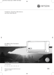
21475 Whispa Manual - US:Layout 1
8/5/09
09:34
Page 1
MYSON Inc. 948 Hercules Drive, Suite 5, Colchester, Vermont VT05446
T: (802) 654-7500, F: (802) 654 7022, [email protected], www.mysoninc.com
Installation, Operating, Maintenance
and After Sales Manual.
WHISPA III ® 5000, 7000 & 9000
heatingthroughinnovation.
heatingthroughinnovation.
01.05.2009 ISSUE 1
Product Serial Number:
Installation Date:
Part Number: 1371051
Issue 1
Tested to UL & CSA Standards
21475 Whispa Manual - US:Layout 1
8/5/09
09:34
Page 3
WHISPA III ® 5000, 7000 & 9000
G No rear access shall be available to the unit after installation.
2.0
Heating System Design
03
G MYSON WHISPA III® fan convectors are designed to be used
with mono-flo Tees from a series loop, on a two pipe
system, or as a stand alone zone.
G Before proceeding with the installation, the heating system
design must be considered and the unit correctly sized to
meet the heat loss requirements of the room.
3.0
Selection and Sizing for Heating
03
4.0
Location
03
6.0
Preparation
Electrical Connection
03
04
Water Connection
G WHISPA III ® units have different pipe centres and wiring
positions than previous WHISPA II® units.
For optimum fan convector heating performance the system
must be capable of providing sufficient hot water through the
heat exchanger. This means that:
1. Care must be taken in sizing both the pump and piping.
The minimum pipe size from boiler to fan convector must be
1/ 2" copper tube.
3. This unit must not be installed in series in a baseboard loop.
4. The system water must be above 110°F for fan to switch on,
and for satisfactory operation the mean water temperature
should not be below 140°F.
5. Optimum performance will require effective balancing of the
whole system.
6. This unit should not be used to replace a radiator in an
existing system unless an adequate flow of water can be
guaranteed through the unit.
7. The loop must be pumped. WHISPA III ® fan convectors are
not suitable for gravity circulation systems.
05
3.0 Selection and Sizing for Heating
8.0
9.0
Fitting the WHISPA III ®
Technical Data
06
G Heat output performance is given in the Technical Data
section of this manual.
G The higher fan speed can then be used for more rapid
heating from cold in extreme conditions.
07
G Since WHISPA III® units are supplied with fan speed control it
is important to size the unit to match the calculated heat loss
requirements of the room with the unit operating at the low
fan speed.
G When establishing the temperature difference, i.e. entering
water to room temperature, allowance should be made for
temperature drop in the system. It is the water temperature
at the fan convector which dictates the output.
4.0 Location
10.0
11.0
Operating Instructions
Troubleshooting
09
10
G This WHISPA III ® unit is designed for installation in the
cavity beneath cupboards in kitchens or other similar
locations on the vacant floor space.
G Once installed there must be enough space around the unit to
allow air movement.
G When installed in a kitchen consideration should be given to
12.0
Maintenance
11
1.0
G WHISPA III® units are not designed for use with steam.
2.0 Heating System Design
2. Where the unit is fitted on to a system with other emitters,
mono-flo Tees or diverter Tees should be used to provide
adequate water flow.
7.0
G In summer mode the fan can be operated to circulate a flow
of air without any heat supply.
G Flexible hoses with integral isolating valves can be used to
allow easy insallation and future access for maintenance.
This fan convector can be fitted on a series loop with mono-flo
or venturi Tees, on a two pipe system or as a stand alone zone.
5.0
G In heating mode a low limit thermostat prevents the fan from
operating if the heating system water temperature is below
110°F.
2.0
03
G WHISPA III® fan convectors are supplied with integral controls
including fan speed selector and summer/winter switch.
3.0
General Information
G This MYSON WHISPA III ® fan convector is designed for
installation in the cavity beneath kitchen cupboards on the
vacant floor space, or other similar locations.
5.0 Preparation
Before proceeding with the installation, unpack the carton
contents and check against the checklist below:
1. WHISPA III® unit.
2. Instruction manual.
3. Grille.
4. Screw fixing kit (with grille).
4.0
1.0
1.0 General Information
storage of perishable goods in the cupboard above.
G The unit should be mounted on a clean and level floor area
under the cupboard base.
G Care must be taken to ensure the installer fully cuts the plinth
to allow air movement through the grille.
5.0
Contents
03
21475 Whispa Manual - US:Layout 1
04
8/5/09
09:34
Page 5
WHISPA III ® 5000, 7000 & 9000
5.0 Preparation
WHISPA III ® 5000, 7000 & 9000
05
7.0 Water Connection
(continued...)
G A clean and level floor area is required under the cupboard
base.
For ease of installation and maintenance WHISPA III ® units should be installed with flexible hoses, with integral isolating valves.
Flexible hoses are supplied only with the WHISPA III ® EZ units.
Dimensions (in)
G Floor mounting - WHISPA
is normally fitted directly onto
the floor and the base of the unit is fitted with four mounting
feet.
Model
A
B
G Decide the position of the WHISPA III ®, mark out and cut the
plinth to the dimensions of Fig. 1 (floor mounting).
5000
18 3/8
4
7000
20 1/2
4
9000
22 5/8
4
III®
Pipework must be positioned correctly to ensure flexible hoses are not kinked when installed. See Fig. 2.
WALL
WALL
A = Width of cutout
B = Height of cutout
Note: unit dimensions given in Technical Data section 9.
10"
12"
A
16"
4"
5.0
B
6.0 Electrical Connection
WARNING: This appliance must be grounded.
Fig. 2a Left hand view - suggestion only
Fig. 2b Right hand view - suggestion only
G Connect valve ends of the flexible pipes to the WHISPA III ®.
Flexible pipes
Note: The direction of the arrows on the EZ flexible hosevalves
are not significant in this application.
7.0
G The electrical installation must comply with local or national
wiring regulations.
6.0
Fig. 1 Plinth opening - floor mounting
G This unit is supplied fitted with 8ft of 18awg cord with plug.
Do not energize the electrical supply until the remaining stages of the installation have been completed.
Isolating valves
Fig. 3
G Open valves fully, check pipe connections for leaks and vent
the heat exchanger. A vent screw is provided to vent the heat
exchanger.
Air vent screw
Fig. 4
21475 Whispa Manual - US:Layout 1
06
8/5/09
09:34
Page 7
WHISPA III ® 5000, 7000 & 9000
WHISPA III ® 5000, 7000 & 9000
8.0 Fitting the WHISPA III ®
8.0 Fitting the WHISPA III ®
G Position the WHISPA III® under the cupboard in the required
location, with the front edge just behind the line of the plinth.
G Ensure that the flexible hoses are not kinked and that the
electrical cord is not in contact with hot surfaces.
G Replace the plinth and bring the WHISPA III® forward into the
opening so the front edge projects 5 / 16 inch through the
plinth.
07
(continued...)
G Complete the electrical installation, switch on and test the
WHISPA III®.
Summer/Winter switch
Switch for fan
Boost
Off
Normal
Top view of unit
Fig. 7
9.0 Technical Data
5/16 inch projection
Fig. 5
WHISPA III ® Unit Dimensions
Dimensions (in)
G Secure the unit/grille to the plinth with two screws supplied
(use the longer screws).
View on arrow
Cable Entries
2 1/8"
15/16"
1/2"
3 15/16 "
2 5/8"
Model
A
B
5000
19 1 /2
12 11/16
7000
21 5 /8
14 9/16
9000
23 3/4
17 9/16
8.0
G Align the grille and secure it to the unit with two screws
supplied (use the shorter screws).
Top view
Front view of unit
9.0
2 1 /4 "
12 3/16" 1 7 /16 "
Cable Entry
1"
5 1/16"
B
FRONT GRILLE
4"
Grille securing screws
Unit securing screws
Fig. 6
A
Fig. 8
21475 Whispa Manual - US:Layout 1
08
8/5/09
09:34
Page 9
WHISPA III ® 5000, 7000 & 9000
9.0 Technical Data
WHISPA III ® 5000, 7000 & 9000
10.0 Operating Instructions
(continued...)
This unit is controlled by the switches on the front of the unit.
Heating Performance Data
Model
Fan Setting
Boost
5000
Normal
Boost
Normal
Boost
7000
Normal
Boost
Normal
Boost
9000
Normal
Boost
Normal
Flowrate
(US gpm)
3
1
3
1
3
1
Ensure the electricity supply is switched on.
Heat Output (Btu/h)
Entering Water Temperature (°F), Entering Air Temperature (65°F)
110
120
130
140
150
160
170
180
190
200
2040
2516
2997
3480
3967
4457
4949
5443
5939
6437
1749
2096
2437
2773
3104
3432
3756
4078
4397
4713
1795
2214
2637
3063
3491
3922
4355
4790
5226
5664
1539
1844
2144
2440
2732
3020
3306
3589
3869
4147
2758
3419
4089
4766
5450
6140
6834
7534
8238
8946
1673
2204
2771
3373
4004
4665
5351
6062
6797
7554
2427
3009
3598
4194
4796
5403
6014
6630
7249
7872
1473
1939
2439
2968
3524
4105
4709
5335
5981
6648
3759
4629
5504
6385
7271
8160
9053
9949
10848
11750
3266
3916
4556
5185
5807
6422
7031
7634
8233
8827
3308
4073
4844
5619
6398
7181
7967
8755
9546
10340
2874
3446
4009
4563
5110
5652
6187
6718
7245
7767
Heating Mode
The fan will only operate when
• The central heating boiler is on
• The pump is running
• The system water temperature is greater than 110°F.
Low Limit Operation
The low limit thermostat fitted to the WHISPA III ® will ensure
that the fan stops after the heating system is switched off and
the water flow stops. If left in an operating position the unit will
automatically restart when the heating system is reheated.
Off Position
Set the fan speed selector switch to the off (O) position.
Ensure boiler is on, and set timer, boiler controls and room
thermostats as necessary.
Summer Mode
•
•
•
•
If required, the WHISPA III ® can be used in summer for air
circulation without heat.
Set summer - winter switch to
Adjust fan speed to required setting.
Turn room thermostat to a high setting.
Set summer - winter switch to
Set fan speed control position I.
The unit will now run on low fan speed. For satisfactory
operation the mean water temperature should not be below
140°F.
Temperature Control
Maximum inlet water temperature 200°F
Heat outputs tested in accordance with BS 4856 Part 1
Supply: 110V AAC 60Hz
Max working pressure: 145psi
Water connections: 1/2" Sweat
The room thermostat setting should be gradually adjusted to
obtain the desired temperature.
The fan speed can be set to boost by switching the fan speed
switch to II.
Approximate Hydraulic Resistance through Units
g/min
09
Weight, Water Content and Motor Power
ft wg
Model
Motor
Power (W)
Water
Content (fl oz)
Unit Weight
(lbs)
5
9.5
5000
7000
9000
3
4.90
5.90
6.89
5000
25
1
0.75
0.85
1.07
7000
40
10
10.3
9000
40
11.5
11
A low speed setting is recommended for normal operation with
the higher speeds for boost heating when required.
MOTOR
y
LINE (Supply)
NEUTRAL (Supply)
bk
Fan Selector
Switch
w
gr
10.0
GROUND
r
9.0
w
Chassis
Earth
Summer/Winter
Switch
w
w
LOW LIMIT
THERMOSTAT
Fig. 9 Wiring diagram
bk
w
gr
y
r
-
black
white
green
yellow
red
21475 Whispa Manual - US:Layout 1
09:34
Page 11
WHISPA III ® 5000, 7000 & 9000
WHISPA III ® 5000, 7000 & 9000
11.0 Troubleshooting
11
12.0 Maintenance
installer or MYSON. Before calling your installer or MYSON,
please carry out the checks listed below.
Once installed this fan convector becomes an integral part of a
complete heating system that includes boiler, pump, other
emitters such as radiators and fan convectors, and a number of
heating controls, dependent on system complexity. An apparent
problem with this unit may be the result of system controls being
incorrectly set and can be solved easily without calling out your
Problem
Before undertaking any maintenance activity isolate the
electrical supply.
Maintenance should be restricted to occasional removal of dust
and lint around the front grille.
This should involve internal cleaning of the heat exchanger using
a soft brush or vacuum cleaner, taking care not to damage fan or
heat exchanger.
This unit should be serviced periodically by a competent person.
Spares List
Possible Causes
Remedy
Room thermostat not calling for heat
Turn up room thermostat
Description
Part Number
Quantity
Unit not switched on at breaker panel
Switch on breaker
Motor / Fan Assembly WHISPA III® 5000
7100088
1
Breaker tripped at panel
Check all wiring, reset breaker
Motor / Fan Assembly WHISPA III® 7000
7100089
1
Heating Mode -
Water temperature reaching unit
Check boiler -
Motor / Fan Assembly WHISPA III® 9000
7100090
1
No Fan
below 110°F
Programmer ON
Switch, 3 way
1300025
1
Boiler ON and set to high
Switch, 2 way
1300024
1
Circulating pump running
Low Limit Thermostat
1260007
1
Wiring Harness
3001047
1
15mm Valve & Flexible Hose
1252007
2
Brown Grille, WHISPA III® 5000
5000054
1
Brown Grille, WHISPA III® 7000
5000058
1
Brown Grille, WHISPA III® 9000
5000129
1
White Grille, WHISPA III® 5000
5000053
1
White Grille, WHISPA III® 7000
5000057
1
White Grille, WHISPA III® 9000
5000128
1
Black Grille, WHISPA III® 5000
5000061
1
Black Grille, WHISPA III® 7000
5000062
1
Black Grille, WHISPA III® 9000
5000130
1
Note: Operation of fan convector can be checked by
switching to summer setting
Heating Mode Poor heating
performance and/or
unit cycles on
low limit thermostat
Low water temperature to unit
Turn up boiler thermostat
Poor water flow
Vent air from heating system
If the fan convector is still faulty after checking the above, call your installer or MYSON.
Common Installation Faults
For optimum performance, this unit must be correctly sized to
match the heat loss requirements of the space it is required to
heat, and the heating system must be correctly designed to
provide adequate flow of hot water to the unit (see Section 2).
If the recommendations in Section 2 are not followed,
problems may arise as detailed below.
Problem
Possible Causes
Poor heating
performance
Unit incorrectly sized for heat loss of room
Boiler thermostat set too low
Lack of flow to fan convector Pump set on low setting
Isolating valves not fully open
System incorrectly balanced with unit starved of hot water flow
Pipe sizing to unit too small
11.0
Poor heating
performance
(unit may cycle on
low limit thermostat)
12.0
10
8/5/09
21475 Whispa Manual - US:Layout 1
8/5/09
09:34
Page 1
MYSON Inc. 948 Hercules Drive, Suite 5, Colchester, Vermont VT05446
T: (802) 654-7500, F: (802) 654 7022, [email protected], www.mysoninc.com
Installation, Operating, Maintenance
and After Sales Manual.
WHISPA III ® 5000, 7000 & 9000
heatingthroughinnovation.
heatingthroughinnovation.
01.05.2009 ISSUE 1
Product Serial Number:
Installation Date:
Part Number: 1371051
Issue 1
Tested to UL & CSA Standards