1
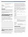
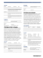
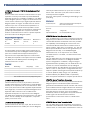
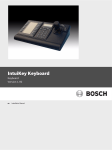
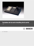
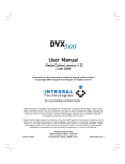
CCTV | Accessories & Software Packages for the Allegiant
Accessories & Software Packages for the
Allegiant
The Allegiant accessory products provide many optional
features to the base Allegiant Video Switcher/Control
System. Various accessory products are available,
including operator keyboards, code distribution units,
data converters, receiver/drivers, and various port
expanders. Where applicable, all accessory products are
designed to be compatible throughout the Allegiant
systems.
In addition to Allegiant accessories, this data sheet also
includes brief information on other products typically
used with the Allegiant Series of matrix switchers.
In some cases, complete information for a product is
found in a separate datasheet.
Accessory Items
LTC 8563 Series
Receiver/Drivers
LTC 8564 Series
Receiver/Drivers
LTC 8566 Series
Receiver/Drivers
LTC 8569 Series
Code Merger Units
LTC 8570 Series
Code Merger Units
LTC 8571 Series
Code Merger Units
LTC 8572 Series
Code Merger Units
LTC 8770 Series
Relay Units
LTC 8712 Series
Console Port Expander Units
LTC 8713 Series
Alarm Port Expanders
LTC 8714 Series
Keyboard Port Expanders
LTC 8715 Series
Keyboard Port Expanders
LTC 8780 Series
Data Converter Units
LTC 8781 Series
Time/Date Converter Units
Description
LTC 8782 Series
Code Translator Units
Keyboard
LTC 8785 Series
Code Converter Units
LTC 8555 Series
Keyboard
LTC 8786 Series
Code Converter Units
LTC 8558/00
Keyboard Extension Cable
LTC 8016/90
Bilinx Data Interface Unit
LTC 8557 Series
Keyboard Extension Kits
LTC 8808/00
Video Interconnect Panel/Cables
Signal Distribution Unit
LTC 8807/00
Video Interconnect Panel
LTC 8768/00
Signal Distribution Unit
LTC 8809 Series
Ribbon Cables
LTC 8540/00
Alarm Interface Unit
LTC 8506/00
Cable, PC-to-Console Port
AutoDome Series
PTZ Cameras
LTC 8508/01
Ribbon to BNC Interface Cable
LTC 8560 Series
Receiver/Drivers
LTC 8561 Series
Receiver/Drivers
LTC 8562 Series
Receiver/Drivers
Model No.
IntuiKey Series
LTC 8568/00
www.boschsecurity.com
2 | Accessories & Software Packages for the Allegiant
Windows®-based Software Packages
Technical Specifications
General Specifications
Model No.
Application
LTC 8059/00
Master Control Software
LTC 8850/00
Graphical User Interface
Environmental
ADIM
DVR Integration Software
SFT-INTSRV
Allegiant Integration Software
Note: Specifications for electronic hardware products are noted below unless otherwise specified in applicable accessory section.
Certifications and Approvals
Electromagnetic Compatibility (EMC)
Complies with FCC Part 15, ICES-003 and CE regulations
Product Safety
Complies with CE regulations, UL, CSA, EN and IEC Standards
Temperature
Operating
4°C to 50°C (40°F to 122°F)
Humidity
0% to 95% relative, non-condensing
Shock
50 g, 11 ms, ½ sine
Altitude
3000 m (10,000 ft)
IntuiKey Keyboard
The IntuiKey KBD-Universal is a full function keyboard
used for control and programming of the Allegiant Series
matrix switchers. Backlit LCD screens provide multilanguage display of softkey menus and status
information. Integral variable speed joystick and zoom
lens controls are standard for operating fixed or variable
speed pan/tilt/zoom equipped cameras. In addition to
the Allegiant Series, the KBD- Universal model IntuiKey
can be used to simultaneously control Divar Series
DVRs, System4 Series multiplexers, and access ADIM
based DVR control screens.
The optional PC based KBD-SFTCFG software package
can be used to customize the text of IntuiKey softkeys
and to define softkeys that are used to activate Allegiant
system Command Scripts.
The optional KBD-RACK rack-mounting kit is designed to
provide vertical, horizontal, or 45 degree inclined
mounting into standard EIA 48 cm (19 in.) rack.
Refer to the IntuiKey Series data sheet for complete
specifications.
LTC 8555 Series Keyboards
The LTC 8555 Series are compact, full function
keyboards for use with Allegiant Series matrix switchers.
LED readouts display real time system status
information. Includes variable speed joystick and zoom
lens controls for operating fixed or variable speed pan/
tilt/zoom equipped cameras. The keyboards are
available in the following configurations:
Model Number
Top Bezel Graphics
Communication Protocol
LTC 8555/00
English
RS-485
LTC 8555/01
Icons
RS-485
LTC 8555/02
English
RS-232
LTC 8555/03
Icons
RS-232
Accessories & Software Packages for the Allegiant | 3
Electrical
applicable to the LTC 8100, LTC 8200, and the LTC 8300
Series systems.
Operating Voltage
12 VAC (supplied by main Allegiant CPU bay or optional
Keyboard Extension Kit)
Signal
Two wire RS-485, 9600 baud (LTC 8555/00 and
LTC 8555/01 models) Three wire RS-232, 9600 baud
(LTC 8555/02 and LTC 8555/03 models)
Operating Voltage
12 VAC (supplied by main CPU bay)
Power
3W
One (1), 6-contact connector for data/power
Indicators
Connectors
Mechanical
Construction/finish
High impact plastic case with charcoal color
Dimensions
(W x D x H)
220 x 51 x 155 mm (8.67 x 2.00 x 6.11 in.)
Weight
0.55 kg (1.22 lb)
Electrical
•
•
Power
LED
Code
LED
Connectors
Input
One (1), 9-pin Sub D connector for data/power
Outputs
Sixteen, 6-contact removable screw terminal blocks for
code output. Maximum transmission distance is 1.5 km
(5000 ft) using 1 mm2 (18 AWG) shielded-twisted pair
(Belden 8760 or equivalent).
LTC 8558/00 Keyboard Extension Cable
Six-conductor extension cable carries data/power for
remote IntuiKey Series or LTC 8555 Series keyboards up
to 30 m (100 ft) away from main Allegiant CPU bay.
Mechanical
Construction/Finish
Charcoal colored metal enclosure
LTC 8557 Series Keyboard Extension Kits
Dimensions
(W x D x H)
445 x 318 x 89 mm (17.5 x 12.5 x 3.5 in.)
Integral mounting flanges for EIA 48 cm (19 in.) rack.
Weight
1.8 kg (4 lb)
Interface kit used to remote IntuiKey Series or LTC 8555
Series keyboards up to 1.5 km (5000 ft) away from main
CPU bay. Customer supplied 0.5 mm2 (24 AWG)
shielded-twisted pair (Belden 9841 or equivalent)
required between main CPU bay site and keyboard site.
Kit provides two junction boxes, interface cable, and
appropriate keyboard power supply.
Electrical
Model No.
Rated Voltage1
LTC 8557/60
120 VAC, 50/60 Hz 108 to 132
Voltage Range
Power
10 W
LTC 8557/50
230 VAC, 50/60 Hz 198 to 264
15 W
1. Input voltage of included power supply.
Indicators
Junction box mounted power LED
Connectors
One (1), 4-position screw terminal block. One (1), 6-contact
keyboard cable connector.
Mechanical
Construction/Finish
Surface mountable, flat black painted metal enclosure
Dimensions
(W x D x H)
121 x 70 x 35 mm (4.75 x 2.75 x 1.375 in.)
Weight
170 g (6 oz.)
LTC 8568/00 Signal Distribution Unit
Main site Bi-Phase control code distribution and line
driver unit for communicating to AutoDome Series
cameras, receiver/drivers, switcher/ followers, and
Allegiant satellite systems. The unit provides 32
separate outputs for driving up to 256 remote devices.
Either “star” or “daisy chain” wiring configurations may
be used. Two meter (6 ft) interface cable for data/power
between unit and main Allegiant CPU bay supplied. Not
LTC 8768/00 Signal Distribution Unit
Same features and specifications as the LTC 8568/00
except that it contains twice the number of output
connectors which provide 64 separate outputs for
driving up to 512 remote devices. Not applicable to the
LTC 8100, LTC 8200, and the LTC 8300 Series systems.
LTC 8540/00 Alarm Interface Unit
Unit accepts up to 64 contact closures or logic level
inputs from remote sensing devices such as door
contacts, PIRs, etc. and then reports the “alarm”
information to the main Allegiant CPU bay. Alarm inputs
may be configured in groups of 32 to accept either
normally open or normally closed contacts. Unit also
contains eight relay outputs that activate automatically
upon alarm conditions. A two meter (6 ft) interface cable
for data/power between unit and main CPU bay is
supplied. Not applicable to the LTC 8100, LTC 8200, and
the LTC 8300 Series systems.
Electrical
Operating Voltage
12 VAC or 12 VDC
(12 VAC is supplied by main CPU bay)
Power
8W
Indicators
Power
LED
Alarm
LED; audible tone
Connectors
Alarm Inputs
Sixty-four (64); Twenty 6-contact removable screw terminal blocks
www.boschsecurity.com
4 | Accessories & Software Packages for the Allegiant
Alarm Outputs
Eight (8) relay outputs (100 VDC, 0.5 A, 10 W); Four (4),
6-contact removable screw terminal block.
Data/Power
One 9-pin Sub D connector
Mechanical
Construction/Finish
Charcoal colored metal enclosure
Dimensions
(W x D x H)
445 x 318 x 89 mm (17.5 x 12.5 x 3.5 in.)
Integral mounting flanges for EIA 48 cm (19 in.) rack
Weight
1.8 kg (4 lb)
AutoDome Series
The AutoDome Series of cameras integrates high-speed
panning and tilting, 360-degree continuous rotation,
pre-positions, etc. in a small, easy-to-install lightweight
package. AutoDome models are available with various
mounting and configuration options for use in both
internal and external environments.
Refer to the AutoDome® Series datasheet for complete
specifications.
LTC 8560, LTC 8561, LTC 8562, LTC 8563, LTC 8564,
and LTC 8566 Series Receiver/Drivers
These series of on-site receiver/drivers are designed to
receive Bi-Phase control code and convert this data into
signals for controlling conventional pan/tilt, zoom
lenses, and auxiliary functions. Supplied in an
environmentally rated enclosure, these series of
receiver/drivers are available in both basic and fullfeatured models. Refer to the chart below for specific
model selection based on desired operating voltages
and features:
Satellite systems. The LTC 8569, LTC 8570 Series
provides 32 separate outputs capable of driving up to
256 remote devices. The LTC 8571, LTC 8572 Series
provides 64 separate outputs capable of driving up to
512 remote devices. Either “star” or “daisy chain” wiring
configurations may be used. Two data cables for
interface to Allegiant main CPU bays are supplied (four
with LTC 8570 and LTC 8572).
Unit will accept signal input either from Allegiant main
CPU bay, LTC 8568/00 output, LTC 8780 Bi-Phase
output, or an output from another LTC 8569, LTC 8570
Series or LTC 8571, LTC 8572 Series unit. Multiple units
may be cascaded to obtain additional outputs.
Electrical
Model No
Rated Voltage
Voltage Range
Power
LTC 8569/60,
LTC 8570/60,
LTC 8571/60,
LTC 8572/60
120 VAC, 50/60 Hz
108 to 132
12 W
LTC 8569/50,
LTC 8570/50,
LTC 8571/50,
LTC 8572/50
230 VAC, 50/60 Hz
198 to 264
12 W
Indicators
Power
LED
Code
LED
Connectors
Inputs
Two (2), 9-pin Sub D connectors (four (4) with LTC 8570 Series
and LTC 8572 Series).
Outputs
Sixteen (32 on LTC 8571 and LTC 8572 Series) 6-contact removable screw terminal blocks for code output. Maximum transmission distance is 1.5 km (5000 ft.) using 1 mm2 (18 AWG)
shielded-twisted pair (Belden 8760 or equivalent).
AC Input
3-wire power cord with grounded plug; 1.8 m (6 ft) long
Model
Features
Input Voltage
P/T Output Voltage
LTC 8560/60
Basic
120 VAC
120 VAC
LTC 8560/50
Basic
230 VAC
230 VAC
LTC 8561/60
Full
120 VAC
120 VAC
LTC 8561/50
Full
230 VAC
230 VAC
Construction/Finish
Charcoal colored metal enclosure
Dimensions
(W x D x H)
445 x 318 x 89 mm (17.5 x 12.5 x 3.5 in.). Integral mounting flanges for EIA 48 cm (19 in.) rack.
Weight
5.3 kg (11.7 lb)
Mechanical
LTC 8562/60
Basic
120 VAC
24 VAC
LTC 8562/50
Basic
230 VAC
24 VAC
LTC 8563/20
Basic
24 VAC
24 VAC
LTC 8564/20
Full
24 VAC
24 VAC
LTC 8770 Series Relay Units
LTC 8566/60
Full
120 VAC
24 VAC
LTC 8566/50
Full
230 VAC
24 VAC
The LTC 8770 Series are relay units that are designed to
operate with devices that generate Allegiant Bi-Phase
control code. These devices include the Allegiant series
of video matrix switcher/controllers, System4 series of
multiplexers, LTC 5136 controller series, etc. The
LTC 8770 receives Bi-Phase control signals and opens or
closes relays, depending upon the desired operating
mode. Each LTC 8770 unit provides 24 individually
isolated relays for connecting to external devices. In
addition, six functional operating modes are available,
including one user activated test mode.
Refer to the LTC 8560 Series and/or LTC 8561 Series datasheets for complete
specifications.
LTC 8569, LTC 8570, LTC 8571, LTC 8572 Series Code
Merger Units
Control code merger and line driver units used to
combine Allegiant Bi-Phase control code from two (up
to four with LTC 8570 and LTC 8572 versions) systems
for communicating to AutoDome Series cameras,
receiver/drivers, switcher/followers, and Allegiant
Accessories & Software Packages for the Allegiant | 5
Mechanical
Electrical
Model No.
Rated Voltage
Voltage Range
Power
LTC 8770/50
230 VAC, 50/60 Hz
198 to 264
8W
LTC 8770/60
230 VAC, 50/60 Hz
105 to 132
8W
Indicators
Power and data transmission activity displayed using LEDs. Device number or logical relay number indicated by a 4-position
thumbwheel switch located on the rear panel.
Connectors
Inputs
One (1), 3-pin removable screw terminal connector, located on
the rear panel; communication port where Bi-Phase commands
are received
Outputs
Four (4), 12-pin removable screw terminal connectors located
on the rear panel; relay contact (0.5 A at 20 VAC/DC and a maximum resistive load of 10 VA) 36 peak volts from either pin of the
relay to ground
AC Input
3-wire power cord with grounded plug; 1.8 m (6 ft) long
Construction/Finish
Steel chassis with sheet metal cover and plastic
bezel. Charcoal colored case.
Dimensions
(W x D x H)
223 x 280 x 40 mm (8.77 x 11 x 1.59 in.)
Weight
1.9 kg (4.3 lb)
Optional Rack Mount Kit
LTC 9101/00 (Holds 1 or 2 units)
LTC 8713 Series Alarm Port Expander
Construction/Finish
Steel chassis with sheet metal cover and plastic
bezel. Charcoal colored case.
Dimensions
(W x D x H)
223 x 280 x 40 mm (8.77 x 11 x 1.59 in.)
Weight
1.9 kg (4.3 lb)
The LTC 8713 Series interfaces to a LTC 8500, LTC 8600,
LTC 8800, or LTC 8900 Series alarm port to permit
additional LTC 8540/00 Alarm Interface units to be
connected to the system. A single LTC 8713 series alarm
port expander supports up to four LTC 8540/00 alarm
interface units. This provides the capability for up to 256
alarm input points. Multiple LTC 8713 units may be
combined to provide up to 1024 alarm input points using
up to sixteen LTC 8540/00 units. The actual number of
units that can be used in a system depends upon the
model of the Allegiant system being used. System
interconnect cable is included. A separate 12 VAC or DC,
8 W power supply is required for each LTC 8540/00.
Optional Rack Mount Kit
LTC 9101/00 (Holds 1 or 2 units)
Alarm Capacities
Mechanical
LTC 8712 Series CONSOLE Port Expanders
The LTC 8712 Series “expands” an Allegiant system's
CONSOLE port to permit up to 4 external computing
devices to communicate with the system via RS-232
protocol. Any computing device that can normally
communicate directly with an Allegiant via its RS-232
CONSOLE port can be used with these port expanders.
The external devices can consist of PCs running the
Allegiant system's Master Control Software package, the
Allegiant Graphical User Interface (GUI), access control
systems, LTC 8555/02 RS-232 keyboards, or other
devices utilizing the Allegiant system's Command
Console Language (CCL). The LTC 8712 Series can be
used with the LTC 8100, LTC 8200, LTC 8300, LTC 8500,
LTC 8600, LTC 8800, or LTC 8900 Series systems
containing CPU software version 6.5 or higher.
Electrical
Model No.
Rated Voltage
Voltage Range
Power
LTC 8712/60
120 VAC, 50/60 Hz
108 to 132
10 W
LTC 8712/50
230 VAC, 50/60 Hz
198 to 264
10 W
Indicators
Power and data transmission activity displayed using LEDs
Connectors
Inputs
One (1), 9-pin Sub D connector; provides RS-232 interface to
Allegiant bay. Two-meter (6-ft) interconnect cable to main bay
supplied
Outputs
Four (4), 9-pin Sub D connectors for RS-232 interface to up to
four external devices
AC Input
3-wire power cord with grounded plug; 1.8 m (6 ft) long
Allegiant Model No. Maximum No. of
Alarms
Maximum No. of
LTC 8713
Maximum No. of
LTC 8540/00
LTC 8500
128
1
2
LTC 8600
512
3
8
LTC 8800
1024
5
16
LTC 8900
1024
5
16
Electrical
Model No.
Rated Voltage
Voltage Range
Power
LTC 8713/60
120 VAC, 50/60 Hz
108 to 132
10 W
LTC 8713/50
230 VAC, 50/60 Hz
198 to 264
10 W
Indicators
Power and data transmission activity displayed using LEDs.
Connectors
Inputs
One (1), 9-pin Sub D connector; provides RS-232 interface to
main Allegiant bay. Two-meter (6-ft) interconnect cable to main
bay supplied.
Outputs
Four (4), non-powered, 9-pin Sub D connectors for RS‑232
interface to up to four expanded LTC 8540/00 units. Data cables supplied with LTC 8540/00 are used to connect alarm
interfaces to port expander. A separate 12 VAC or DC, 8 W
power supply is required for each LTC 8540/00.
AC Input
3-wire power cord with grounded plug; 1.8 m (6 ft) long
Mechanical
Construction/Finish
Steel chassis with sheet metal cover and plastic
bezel. Charcoal colored case.
Dimensions
(W x D x H)
223 x 280 x 40 mm (8.77 x 11 x 1.59 in.)
Weight
1.9 kg (4.3 lb)
Optional Rack Mount Kit
LTC 9101/00 (Holds 1 or 2 units)
www.boschsecurity.com
6 | Accessories & Software Packages for the Allegiant
LTC 8714 Series and LTC 8715 Series Keyboard Port
Expanders
The LTC 8714 Series and the LTC 8715 Series are port
expander accessory units used to provide additional
keyboard capacity for LTC 8600, LTC 8800, or LTC 8900
Series Allegiant systems. A single LTC 8714 Series unit
can be used to interface up to eight keyboards with an
allegiant system. A single LTC 8715 Series is used to
interface up to four LTC 8714 Series expanders in a
system. Multiple LTC 8715 Series expanders can be
used along with multiple LTC 8714 Series expanders to
provide up to 64 keyboards in a system. The actual
number of units that can be used in a system depends
upon the model of the Allegiant system.
Allegiant System Capacities
Allegiant Model
No.
Maximum No. of
Keyboards
Maximum No. of
LTC 8714
Maximum No. of
LTC 8715
LTC 8600
16
1
0
LTC 8800
32
3
1
LTC 8900
64
7
3
The above table assumes eight system keyboards are
connected directly into the Allegiant CPU bay keyboard
ports. An LTC 8557 Series keyboard hookup kit is
required for each expanded keyboard. LTC 8714 and
LTC 8715 port expanders can only be used on LTC 8600,
LTC 8800, and LTC 8900 systems containing CPU
software version 6.2 or later.
Electrical
Model No.
Rated Voltage
Voltage Range
Power
LTC 8714/60
120 VAC, 50/60 Hz
108 to 132
10 W
LTC 8715/60
120 VAC, 50/60 Hz
108 to 132
10 W
LTC 8714/50
230 VAC, 50/60 Hz
198 to 264
10 W
LTC 8715/50
230 VAC, 50/60 Hz
198 to 264
10 W
Indicators
Power and data transmission activity displayed using LEDs
CPU bay and data interface for up to four LTC 8714
Series units. Two-meter (6-ft) interconnect cable for
main bay interface supplied.
AC Input: 3-wire power cord with grounded plug; 1.8 m
(6 ft) long.
Mechanical
Construction/Finish
Steel chassis with sheet metal cover and plastic
bezel. Charcoal colored case.
Dimensions
(W x D x H)
223 x 280 x 40 mm (8.77 x 11 x 1.59 in.)
Weight
1.9 kg (4.3 lb)
Optional Rack Mount Kit
LTC 9101/00 (Holds 1 or 2 units)
LTC 8780 Series Data Converter Units
The LTC 8780 Series are accessory units that convert the
Allegiant system's Bi-Phase control code into RS-232, or
converts RS-232 back to Bi-Phase code. This provides
the capability of transmitting the control code over
conventional RS-232 transmission mediums such as
phone modems, fiber optics, microwaves, etc. The unit
will accept the Bi-Phase control code generated by an
Allegiant main CPU bay, a LTC 8568/00 Signal
Distribution unit, or an output from a LTC 8569,
LTC 8570 Series or LTC 8571, LTC 8572 Series Code
Merger unit.
The LTC 8780 Series are also designed to perform the
Satellite selector functions in an Allegiant Satellite
system configuration. In addition, using its integral
signal distribution capability, the LTC 8780 Series can
function as a remote distribution unit providing 15
separate outputs. As a distribution unit, wiring can be in
either a “star” or “daisy chain” configuration and each
output is capable of driving 8 receiver/driver loads at up
to 1.5 km (5000 ft) away using 1 mm2 (18 AWG)
shielded-twisted pair (Belden 8760 or equivalent).
Refer to separate datasheet for complete specifications.
LTC 8714 Series Connectors
LTC 8781 Series Time/Date Converters
Interface Data Port: One (1), 9-pin Sub D connector
provides data interface to COM 2 port of main Allegiant
CPU bay or to expansion port of LTC 8715 Series. Twometer (6-ft) interconnect cable supplied. Keyboard Data
Ports: Eight (8), 6-contact non-powered Allegiant series
keyboard cable connectors. An LTC 8557 Series
keyboard hookup kits are required for each Allegiant
LTC 8555 series keyboard to be interfaced to LTC 8714
Series. For the IntuiKey Series keyboards, a separate
power pack can be used.
The LTC 8781 Series are accessory units that decode the
Allegiant system's encoded time/date information
generated on the Bi-Phase control code line and convert
it into an RS-422 format using the GPS format. This time/
date information can be used to interface into external
time/date inserter products (such as the Kalatel
KTS-53-16), which are designed to be synchronized via
a GPS signal. The electrical and mechanical
specifications are the same as the LTC 8780 Series
units.
LTC 8715 Series Connectors
LTC 8782 Series Code Translator Units
Interface Data Ports: Five (5), 9-pin, Sub D connectors
provide data interface to COM 2 port of main Allegiant
The LTC 8782 Series Code Translators are accessory
units that convert Bi-Phase code to other manufactures’
control codes, or convert other manufactures’ codes to
Accessories & Software Packages for the Allegiant | 7
Bi-Phase. Many of the most popular protocol codes are
supported, including Pelco, Vicon, American Dynamics,
Sensormatic, Kalatel, Diamond Electronics, and Javelin.
Fixed and variable speed codes are supported where
applicable.
The LTC 8782 Series Code Translators have four
independent outputs. Removable screw terminal blocks
are used for input and output connections. The Front
panel LEDs indicate the status of power, data receive,
and data transmit. The translator comes supplied in an
EIA 48 cm (19 in.) rack-mount adapter that can hold up
to three units.
Refer to the LTC 8782 series data sheet for complete
specifications.
LTC 8785 Series Code Converters
LTC 8785 Series units are designed for use in very old
Allegiant systems that have been upgraded to support
‘variable speed’ control code protocol. The LTC 8785
units are used to provide a source of 'fixed speed'
control code when the system is generating the new
‘variable speed’ control code preferred by the
AutoDome series of PTZ cameras. The LTC 8785 receives
variable speed control code from the Allegiant via its
LTC 8568/00 Signal Distribution unit and converts it into
appropriate fixed speed control code. The ‘fixed speed’
control code outputs from the LTC 8785 Series connect
to the older TC8561 Series receiver/drivers using the
existing field cabling.
Electrical
Model No.
Rated Voltage
Voltage Range
Power
LTC 8785/60
120 VAC, 50/60 Hz
108 to 132
12 W
LTC 8785/50
230 VAC, 50/60 Hz
198 to 265
12 W
Indicators
•
•
Power
LED
Code
LED
Connectors
Inputs
One (1), 9-pin Sub D connector
Outputs
Sixteen (16), 6-contact removable screw terminal blocks for
code output. Maximum transmission distance is 1.5 km (5000 ft)
using 1 mm2 (18 AWG) shielded twisted pair (Belden 8760 or
equivalent).
AC Input
3-wire power cord with grounded plug; 1.8 m (6 ft) long
Mechanical
Construction/Finish
Charcoal colored metal enclosure
Dimensions
(W x D x H)
445 x 318 x 89 mm (17.5 x 12.5 x 3.5 in.)
Integral mounting flanges for EIA 22.86 cm (9 in.) rack
Weight
5.3 kg. (11.7 lb)
LTC 8786 Data Converter Series
The LTC 8786 Series of data converters are designed to
convert Bosch “Receiver/Driver and AutoDome RS-232
Control Code Protocol” into Allegiant Bi-Phase control
code. These units are the preferred method for
transforming the single data output from a DiBos DVR
(or a similar device) into multiple control code outputs
for operating AutoDome cameras. Either “star” or “daisy
chain” wiring configurations can be used from each of
its 16 outputs. Using daisy chain, each output is capable
of driving 8 receiver/driver loads at up to 1.5 km
(5000 ft.) away using 1 mm2 (18 AWG) shielded-twisted
pair (Belden 8760 or equivalent).
Refer to the LTC 8786 series datasheet for complete
specifications.
LTC 8016/90 Bilinx™ Data Interface Unit
The LTC 8016/90 Allegiant Bilinx Data Interface unit is
an accessory used for communicating over-the-coax,
with up to 16 Bilinx-capable AutoDome® and/or Dinion™
Series cameras. Compatible with all seven Allegiant
Series matrix switcher/controllers, the LTC 8016
provides complete control of pan/tilt/zoom, auxiliaries,
and pre-position functions of Bilinx enabled AutoDome
Series cameras. In addition, complete programming of
Dinion Series cameras and AutoDomes via their onscreen menus is supported.
Bilinx technology also supports camera-generated event
reporting to the Allegiant. This allows remote alarm
inputs and motion event data to be sent by the camera
to the Allegiant without the need for additional wiring
between the camera site and the main control location.
In addition, the LTC 8016 is designed so that other BiPhase code generating products, like Bosch Digital
Videos Recorders, can be used with the unit for control
of PTZ functions and camera menu access over the video
cable.
The LTC 8016 is supplied in an enclosure compatible
with mounting in an EIA 48 cm (19 in.) rack, requiring
only a 1-U rack height. To support large systems, up to
31 units can be cascaded, comprising up to 496 Bilinxcompatible cameras.
The LTC 8016 can also be used to transmit Bilinx
communications over a number of video transmission
systems. Example devices include fiber optic links and
external balun devices that use CAT5 twisted pair cables
for video communication.
Refer to the LTC 8016/90 datasheet for complete
specifications.
LTC 8808/00 Video Interconnect Panel
The LTC 8808/00 Video Interconnect panel provides the
LTC 8200, LTC 8300 Series, LTC 8600 Series, and
www.boschsecurity.com
8 | Accessories & Software Packages for the Allegiant
LTC 8800 Series systems the ability of looping up to 32
video inputs per panel. This 'patch' panel contains 32
BNC connectors on its front panel for external video
connections and two 16-contact ribbon connectors on
its rear panel. Two, 2-meter (6-ft) 16‑conductor video
grade ribbon cables are included for interfacing the
patch panel to the video looping connectors on the rear
panel of the LTC 8200, LTC 8300 Series, LTC 8600
Series, and LTC 8800 Series equipment bays.
Mechanical
Construction/Finish
Charcoal painted metal
Size
One standard EIA 48 cm (19 in.) rack unit high and one unit
wide. Integral mounting flange design.
Weight
0.8 kg (1.8 lb)
LTC 8059 Master Control Software and the LTC 8850
Allegiant GUI packages.
Length: 3 m (10 ft), approximately.
LTC 8508/01 Ribbon-to-BNC Interface Cable
The LTC 8508/01 is a video interface cable with a 34-pin
ribbon cable on one end and 16 male BNC connectors
on the other end. This cable can be used to loop up to
16-channels of video signals from products having the
ribbon cable connector interface to other devices that
utilize BNC connectors. Typical products with 34-pin
ribbon cable connector interfaces include the
LTC 8016/90 Bilinx Data Interface unit and the DESAXL
series digital video recorder.
Length: 1 m (3 ft), approximately
LTC 8807/00 Video Interconnect Panel
LTC 8059/00 Allegiant Master Control Software
The LTC 8807/00 Video Interconnect Panel is identical
to the LTC 8808/00 described above, except that it does
not include the two video ribbon cables. This video
interconnect panel is intended for use with products
that are supplied with video ribbon cables, such as the
LTC 8016/90 Bilinx Data Interface unit.
For example, the ribbon cables from up to two LTC 8016
units can be converted into 32 standard female BNC
connectors using this interface panel. This configuration
is necessary when the LTC 8016 unit will be separated
from the control unit beyond a 2 m (6 ft) distance.
The LTC 8059/00 brings the familiarity of the personal
computer to those who supervise closed circuit
television systems. Running on a Microsoft® Windows
based compatible computer, this software is the human
interface that makes it quick and easy to configure an
entire Allegiant system.
With the Master Control Software (MCS), users can set
and change an Allegiant’s system parameters; program
camera sequences; lock cameras, monitors, remotes,
and keyboards from certain users; and perform many
other system control features. Users can also view
system activity with real time monitoring of the system
status, and if desired, log this information to a file stored
on the hard drive.
The MCS is compatible with all current versions of the
Allegiant Series Video Switcher/Control systems.
Typically, the MCS communicates with the Allegiant
system through a direct RS-232 interface, but it is also
possible to install the MCS on a remote PC connected
across a Windows based network.
Earlier versions of Allegiant systems may be upgraded to
be compatible with the MCS by the installation of
current hardware or software upgrades. Contact your
Bosch Security Systems, Inc. Sales Representative or
Technical Support Representative for details.
• Minimum System Requirements, PC Platform:
- Microsoft Windows® compatible PC, Intel®
Pentium® 120 MHz or greater
- 16 MB RAM (with Windows® 95, 98 SE, or ME)
- 32 MB RAM (with Windows NT, 2000, or XP)
- 250 MB fixed drive space
- CD-ROM drive
• One of the following Operating Systems:
- Windows 98 SE
- Windows ME
- Windows NT (Service Pack 4)
- Windows 2000 (Service Pack 3 or later)
LTC 8809 Series Video Ribbon Cables
The LTC 8809 series are 16-channel video ribbon cables
that are used to provide connections between certain
devices. Specifically designed for the transport of
75 Ohm video signals, these cables are available in three
different lengths:
Model Number
Length
LTC 8809/00
2 m (6 ft)
LTC 8809/01
1 m (3 ft)
LTC 8809/02
3.2 m (10.5 ft)
Each cable contains a 34-pin connector at each end that
is designed to ‘lock’ into the corresponding connector
found on the rear panels of the Allegiant LTC 8800 and
LTC 8900 series matrix switchers. In addition, these
cables are supplied with certain other products,
including the LTC 8808/00 Video Interconnect Panel and
the LTC 8016/90 Bilinx Data Interface unit.
LTC 8506/00 Allegiant Console Cable
The LTC 8506/00 is an RS-232 grade cable with 9-pin,
Sub D-connectors on each end that is used to connect
an Allegiant’s system’s Console port to a standard PC
Com port. This cable is included in the Allegiant
Accessories & Software Packages for the Allegiant | 9
•
•
-
Windows XP Professional
Ports Required (Minimum)
- One (1) parallel port (for software Security Dongle
device) configured for bi-directional operation
(examine BIOS settings if necessary; Note: USB-toparallel port adapters are not compatible)
- One (1) serial port for external interface
communications
- Additional serial ports required if multiple systems
are being interfaced
- SVGA display or compatible display
Software Includes:
- LTC 8059/00 User Manual
- CD-ROM
- Software security key (attaches to PC Parallel port)
- PC-to-system interface cable (S1385)
LTC 8850 Windows Based Allegiant Software
The LTC 8850 Graphical User Interface (GUI) software
is a PC based program designed for complete control
and programming of the Allegiant series of matrix
switchers.
With a mouse click on an icon, operators can easily take
control of system hardware devices, including cameras,
monitors, and alarms. Jumping from one map to another
is easily accomplished using special link icons.
System Administrators can easily call up the included
Allegiant LTC 8059/00 Master Control Software module
for entering the Allegiant system's camera titles,
sequences, alarm responses, and many other
configuration features.
Communication between the GUI workstations and an
Allegiant system can be made using an RS-232 link, or
via a Windows based PC network.
• Minimum System Requirements PC Platform:
- Microsoft Windows® compatible PC, Intel®
Pentium® 120 MHz or greater
- 16 MB RAM (with Windows® 95, 98 SE, or ME)
- 32 MB RAM (with Windows NT, 2000, or XP)
- 250 MB fixed drive space
- CD-ROM drive
• Operating Systems
- Windows 98 SE
- Windows ME
- Windows NT (Service Pack 4)
- Windows 2000 (Service Pack 3 or later)
- Windows XP Professional
• Ports Required (Minimum)
- One (1) parallel port (for software Security Dongle
device) configured for bi-directional operation
(examine BIOS settings if necessary; Note: USB-toparallel port adapters are not compatible)
- One (1) Serial port for external interface
communications
Note
Additional serial ports required if multiple systems
are being interfaced
SVGA display or compatible display
Mouse, trackball, or touch screen pointing device
Note: For a live video display on the PC
monitor, a Windows-compatible Video
Digitizer Card must be used. The FlashBus
MV Lite, supplied by Integral Technologies,
Inc., may be used. For availability, and your
nearest distributor, contact Integral
Technologies, Inc. at 317-845-9242 or
www.integraltech.com.
•
Software Includes:
- LTC 8850/00 User Manual
- CD-ROM
- Software security key (attaches to PC Parallel port)
- LTC 8506/00 PC-to-system interface cable
Refer to the LTC 8850 series datasheet for complete
specifications.
ADIM DVR Interface Software
ADIM is a powerful security and surveillance solution
that combines the robust features of the Bosch Allegiant
matrix switcher with the speed and quality of digital
video recording. This tightly integrated solution uses the
IntuiKey keyboard to control all cameras, monitors and
digital video recorders (see back for compatibility).
Reviewing an event has never been easier. The push of
a single button transforms the IntuiKey into a DVR
controller, allowing instant playback of video from the
current camera, for display on the CCTV monitor. Using
the joystick, one can easily fast forward or fast reverse
to review the recording. Furthermore, Bosch DVRs can
playback and record simultaneously, thus ensuring
uninterrupted recording. ADIM is a rugged, reliable, and
scalable solution, providing a true migration path for
digital recording. Expanding your system is as easy as
replacing a VCR. The ADIM solution uses stand-alone
digital video recorders and incorporates Bosch disk
arrays. ADIM is not restricted by network bandwidth, or
subject to single point catastrophic failures. ADIM
continuously monitors all DVRs for proper recording and
archiving, and status can be viewed or printed. In the
event of a DVR or Disk Array failure, ADIM will display a
message on the CCTV monitors. For added security,
ADIM provides automatic switchover to backup digital
video recorders and DVAS RAID 5 protected disk arrays
with hot swappable drives. In addition, ADIM logs events
and synchronizes the Allegiant and all Digital video
recorder clocks.
Refer to the ADIM datasheet for complete
specifications.
www.boschsecurity.com
10 | Accessories & Software Packages for the Allegiant
SFT-INTSRV Allegiant Integration Software
The SFT-INTSRV software CD contains three distinct
software packages that can be used integrate external
devices with an Allegiant system matrix switcher. Please
refer to the following sections for details:
Integration Server
The Integration Server is a versatile software package
used to integrate multiple systems that are not ordinarily
compatible with each other. These systems can include
Video Switchers, Point of Sale systems, Fire/Burglar
alarms, Access Control, or HVAC systems.
Devices can be interfaced using any of 3 different
methods, including a serial RS-232 connection, a digital
I/O card, or directly to an Allegiant Switcher via the
LTC 8059 Master Control Software program.
The Integration Server software is programmed to
recognize events as they occur in real time from one or
more systems, based upon one of the three integration
methods mentioned above. It then reacts to those
events by sending commands to another system or
systems.
• Minimum System Requirements PC Platform:
- Microsoft Windows® compatible PC, Intel®
Pentium® 120 MHz or greater
- 8 MB RAM (with Windows® 98 SE, or ME)
- 16 MB RAM (with Windows 2000, or XP)
- 250 MB fixed drive space
- CD-ROM drive
• Operating Systems
- Windows 98 SE
- Windows ME
- Windows 2000 (Service Pack 3 or later)
- Windows XP Professional
• Ports Required (Minimum)
- One (1) USB port (or USB hub port) for USB
Security Dongle
- One (1) Serial port for external interface
communications
- Additional serial ports required if multiple systems
are being interfaced–up to 16 supported
- SVGA display or compatible display
- ISA slot if software will be used with National
Instruments™ # PC-DIO-24 Data I/O card
• Software Includes:
- LTC 8050/00 User Manual
- CD-ROM
- Software security key (attaches to PC USB port)
- LTC 8506/00 PC-to-system interface cable
Virtual Allegiant Satellite Application Software
VASA (Virtual Allegiant Satellite Application) is Bosch’s
strategic product that allows existing Allegiant
customers to transition gradually to pure IP
technologies rather than a total and instantaneous
replacement.
VASA acts as the integration bridge between an existing
Allegiant and the new digital based CCTV system (the
‘satellite’) that uses digital video encoders and
decoders. With VASA, the new IP technology is totally
transparent to the existing Allegiant users who continue
to use their IntuiKey CCTV keyboards for video switching
and PTZ control on classic analog monitors.
VASA supports the Allegiant LTC 8100 through the
LTC 8900 Series matrix switchers. In addition to PTZ
control, VASA provides auxiliary and preposition control
of the IP based cameras.
VASA improves the ROI on existing capital assets,
removes the need for training and reduces the risk for
adopting new technology by incrementally adding to the
system. The integration is seamless and the transition is
designed to be imperceptible.
• Recommended PC Platform:
- Microsoft Windows® compatible PC, Intel®
Pentium® 2.8 GHz or greater
- 512 MB RAM (with Windows 2000, or XP)
- 50 MB Fixed Drive space
- CD-ROM Drive
• Operating Systems
- Windows 2000 (Service Pack 3 or later)
- Windows XP Professional
• Ports Required (Minimum)
- 10/100BaseT Ethernet interface
- One (1) USB port (or USB hub port) for USB
Security Dongle
- One (1) Serial port for external interface
communications
- Additional serial ports required if multiple
interfaces are used
- SVGA display or compatible display
To ensure optimal performance, a dedicated PC is
recommended to run this application.
Refer to the VASA datasheet for complete specifications.
Allegiant Satellite SDK
The Allegiant Satellite Software Development Kit (SDK)
is a fully supported set of libraries, documentation, and
samples targeted at PC-based application software that
is used to control third-party CCTV matrix systems or
manage IP-based digital video networks.
Since the SDK can be used to create customized
solutions for unique, specific problems, customers
looking to integrate an Allegiant matrix system with
products offered by other manufacturers is readily
accomplished.
For the thousands of existing Allegiant customers, it also
provides a bridge to integrate or expand their systems
with IP-based products gradually rather than a total and
instantaneous replacement.
When operating in an Allegiant satellite system
configuration, an Allegiant master generates switching
Accessories & Software Packages for the Allegiant | 11
and PTZ data that is typically used to control a remote
Allegiant satellite matrix. Using the SDK, the video
switching commands and PTZ data from the master
system are converted into an ActiveX interface allowing
developers to easily translate this information into
formats used to control other original equipment
manufacturer’s (OEM) systems. The SDK also supports
an ability to translate repetitive type Allegiant PTZ
commands to their indefinite equivalents, resulting in
reduced interface traffic and lower bandwidth demands
when controlling IP-based networks.
The level of integration available with the SDK results in
a robust interface that provides transparent operation
to the existing Allegiant operators. Operators continue
to use their existing CCTV keyboards for selecting video
and control of PTZ devices on the Allegiant monitors.
This type of solution improves the return of investment
on existing capital assets, removes the need for training,
and reduces the risk for adopting new technology by
incrementally adding to the system.
The SDK is compatible with all models of the Allegiant
Series switchers. In addition to video switching
commands and PTZ control, auxiliaries and prepositions
are also supported.
The SDK is supplied with five (5) sample applications.
Three (3) samples use C++ to demonstrate incorporating
the SDK in a Console, ATL, and MFC application. In
addition, samples using Visual Basic®, and
Microsoft’s®.NET Framework are included.
• Recommended PC Platform:
- Microsoft Windows® compatible PC, Intel®
Pentium® 2.8 GHz or greater
- 512 MB RAM
- 50 MB fixed drive space
- CD-ROM drive
• Operating Systems
- Windows 2000 (Service Pack 3 or later)
- Windows XP Professional
• Ports Required (Minimum)
- One (1) Serial port for external interface
communications
- Additional serial ports required if multiple systems
are being interfaced
- SVGA display or compatible display
Refer to the Allegiant Satellite SDK datasheet for
complete specifications.
Ordering Information
Ordering Information
LTC 8555/03 Compact Full Function Keyboard
896085550301
variable speed joystick, RS-232 protocol, icon
graphics
LTC 8540/00 Alarm Interface Unit
896085400001
Alarm interface, 64 alarm inputs, 8 relay closures
LTC 8558/00 Keyboard Cable
optional, 30.5 m (100 feet)
896085580001
LTC 8568/00 Signal Distribution Unit
32 separate biphase outputs
896085680001
LTC 8768/00 Signal Distribution Unit
64 separate biphase outputs
896087680001
LTC 8569/50 Code Merger Unit
896085695001
allows 2 Biphase devices to control 32 outputs,
230 VAC, 50 Hz
LTC 8569/60 Code Merger Unit
896085696001
allows 2 Biphase devices to control 32 outputs,
120 VAC,
50/60 Hz
LTC 8570/50 Code Merger Unit
896085705001
allows 4 Biphase devices to control 32 outputs,
230 VAC, 50 Hz
LTC 8570/60 Code Merger Unit
896085706001
allows 4 Biphase devices to control 32 outputs,
120 VAC, 50/60 Hz
LTC 8571/50 Code Merger Unit
896085715001
allows 2 Biphase devices to control 64 outputs,
230 VAC, 50 Hz
LTC 8572/50 Code Merger Unit
896085725001
allows 4 Biphase devices to control 64 outputs,
230 VAC, 50 Hz
LTC 8572/60 Code Merger Unit
896085726001
allows 4 Biphase devices to control 64 outputs,
120 VAC, 60 Hz
LTC 8712/50 Allegiant Console Port Expander
896087125001
for LTC 8600/LTC 8800 console port expander,
RS-232, 230°VAC, 50 Hz
LTC 8712/60 Allegiant Console Port Expander
896087126001
for LTC 8600/LTC 8800 console port expander,
RS-232, 115°VAC, 60 Hz
LTC 8713/50 Alarm Port Expander
for up to 4 LTC 8540/00 units, half rack,
230 VAC, 50 Hz
896087135001
LTC 8713/60 Alarm Port Expander
for up to 4 LTC 8540/00 units, half rack, 115
VAC, 60 Hz
896087136001
LTC 8714/50 Keyboard Port Expander
for up to 8 Allegiant keyboards, half rack
230 VAC, 50 Hz
896087145001
LTC 8714/60 Keyboard Port Expander
896087146001
for up to 8 Allegiant keyboards, half rack, 115°
VAC, 60°Hz
LTC 8555/00 Compact Full Function Keyboard
variable speed joystick
896085550001
LTC 8715/50 Port Expander
896087155001
for multiple LTC 8714/50 units, 230 VAC, 50 Hz
LTC 8555/01 Compact Full Function Keyboard
variable speed joystick, icon graphics
896085550101
LTC 8715/60 Port Expander
896087156001
for multiple LTC 8714/60 units, half rack, 115
VAC, 60 Hz
LTC 8555/02 Compact Full Functions Keyboard
variable speed joystick, RS-232 protocol
896085550201
www.boschsecurity.com
12 | Accessories & Software Packages for the Allegiant
Ordering Information
LTC 8785/50 Data Converter Unit
converts var. speed to fixed speed code, 230
VAC, 50 Hz
896087855001
LTC 8785/60 Data Converter Unit
converts var. speed code to fixed speed code,
120 VAC, 60 Hz
896087856001
LTC 8808/00 Video Interconnect Panel
Video connect panel
896088080001
LTC 8770/50 Switcher/Follower Unit
896087705001
for Allegiant system, 24 Relay contact, half rack,
230 VAC, 50 Hz
LTC 8770/60 Switcher/Follower Unit
896087706001
for Allegiant system, 24 Relay contact, half rack,
120 VAC, 60 Hz
LTC 8059/00 Allegiant Software for Windows
896080590001
Allegiant systems programming software for Windows 95 and NT
LTC 8506/00 Cable
PC-to-Console port, for Allegiant Systems
896085060001
LTC 8809/00 Ribbon Cable
896088090001
16 conductor for LTC 8200, 8300, 8600, 8800,
8900 Systems, 1,8 m (6 ft)
LTC 8809/01 Ribbon Cable
16 conductor, for LTC 8200, 8300, 8600,
8800, 8900 Systems, 0.9 m (3°ft)
896088090101
LTC 8809/02 Ribbon Cable
16 conductor, for LTC 8200, 8300, 8600,
8800, 8900 Systems, 3°m (9.9°ft)
896088090201
LTC 8781/50 Time/Date Converter Unit
provides output in GPS format, half rack,
230 VAC, 50 Hz
896087815001
LTC 8781/60 Time/Date Converter Unit
provides output in GPS format
896087816001
LTC 8560/50 Single Channel On-site Receiver/Driver 896085605001
230 VAC pan/tilt voltage, 230 VAC power supply,
no auxiliary, 50°Hz
LTC 8560/60 Single Channel On-site Receiver/Driver 896085605001
120 VAC pan/tilt voltage, 120°VAC power supply, no auxiliary,
50/60 Hz
LTC 8780/50 Data Converter Unit
896087805001
Allegiant biphase control code to RS-232, 230
VAC, 50 Hz
LTC 8780/60 Data Converter Unit
896087806001
Allegiant biphase control code to RS-232, 115 V,
60 Hz
LTC 8850/00 GUI Allegiant Single User Software
Package
complete with Allegiant and VCR server
Americas:
Bosch Security Systems
130 Perinton Parkway
Fairport, New York, 14450, USA
Phone: +1 585 223 4060
Fax: +1 800 289 0096
[email protected]
www.boschsecurity.us
896088500001
Europe, Middle East, Africa:
Bosch Security Systems B.V.
P.O. Box 80002
5600 JB Eindhoven, The Netherlands
Phone: +31 40 27 83955
Fax: +31 40 27 86668
[email protected]
www.boschsecurity.com
© Bosch Security Systems 2006 | Data subject to change without notice
F2414677387 | Cur: en-US, V2, 24 Jan 2006 | DocNo. F01U008427_01
Asia-Pacific:
Bosch Security Systems Pte Ltd
38C Jalan Pemimpin
Singapore 577180
Phone: +65 6319 3450
Fax: +65 6319 3499
[email protected]
www.boschsecurity.com
Represented by