1
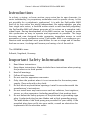
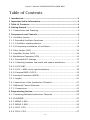
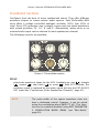
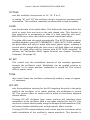
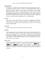
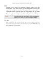
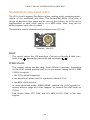
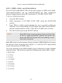
Ownerʻ‘s Manual
Owner's Manual VERMONA PERfourMER MKII
Introduction
In a choir, a string- or brass section, every voice has its own character, its
sonic individuality, its proprietary modulation and its specific decay. Is this
not possible for a polyphonic synthesizer? It is with the PerFourMer MKII!
Each of its four voices are totally independent. No matter whether you play
four single solo voices, a fourfold unison stack or with fourfold polyphony,
the PerFourMer MKII will always generate all its voices on a complete individual basis. During development of the MKII-version, we focused to make
this synthesizer as easy to operate and ergonomic as possible. The large
housing and new designed knobs guarantee immediate access to each
parameter of every synthesizer voice. PerFourMer MKII is an analogue synthesizer with exceptional sonic possibilities for use on stage and in studios.
And we are sure; its design will assure you having a lot of fun with it.
The VERMONA-team
Erlbach /Vogtland, Germany
Important Safety Information
1.
Read these instructions.
2.
Keep these instructions. Alway include these instructions when passing
the product on to third parties.
3.
Heed all warnings.
4.
Follow all instructions.
5.
Do not use this apparatus near water.
6.
Only clean the product when it is not connected to the mains power
supply. Clean only with a dry cloth.
7.
Do not block any ventilation openings. Install in accordance with the
manufacturer's instructions.
8.
Do not install near any heat sources such as radiators, heat registers,
stoves, or other apparatus (including amplifiers) that produce heat.
9.
Do not defeat the safety purpose of the polarized or grounding-type
plug. A polarized plug has two blades and a third grounding prong.
The wide blade or the third prong are provided for your safety. If the
provided plug does not fit into your outlet, consult an electrician for
replacement of the obsolete outlet.
-2-
Owner's Manual VERMONA PERfourMER MKII
10. Protect the power cord from being walked on or pinched, particularly
at plugs, convenience receptacles, and the point where they exit from
the apparatus.
11. Only use attachments/accessories specified by the manufacturer.
12. Use only with the cart, stand, tripod, bracket, or table specified by the
manufacturer, or sold with the apparatus. When a cart is used, use
caution when moving the cart/apparatus combination to avoid injury
from tip-over.
13. Unplug this apparatus during lightning storms or when unused for
long periods of time.
14. Refer all servicing to qualified service personnel.Servicing is required
when the apparatus has been damaged in any way, such as power supply cord or plug is damaged, liquid has been spilled or objects have
fallen into the apparatus, when the apparatus has been exposed to rain
or moisture, does not operate normally, or has been dropped.
15. To completely disconnect this apparatus from the AC mains,
disconnect the power supply cord plug from the AC receptacle.
16. WARNING: To reduce the risk of fire or electric shock, do not expose
this apparatus to rain or moisture.
17. Do not expose this equipment to dripping or splashing and ensure that
no objects filled with liquids, such as vases, are placed on the equipment.
18. The mains plug of the power supply cord shall remain readily accessible.
Installation
• Ensure that the room in which you use this product is wired in accordance
with the local electrical code and checked by a qualified inspector.
• Only use this product indoors.
• Do not install the product in hot, humid, or excessively dusty locations, in
direct sunlight or in locations where it is exposed to externally generated
vibrations.
• Do not place burning objects (e.g. candles) on top of or near the product.
• If condensation has formed on the product, e.g. because it was moved
from a cold environment to a warm one, allow the product to acclimatize
to room temperature before using it.
• Do not overload wall outlets and extension cables as this may result in
fire and electric shock.
-3-
Owner's Manual VERMONA PERfourMER MKII
Table of Contents
1 Introduction ..................................................................................................................2
2 Important Safety Information ...............................................................................2
3 Table of Contents ......................................................................................................4
4 Getting Started ............................................................................................................6
4.1. Connections and Powering ................................................................6
5 Components and Controls .....................................................................................6
5.1. Oscillator Section ..............................................................................7
5.1.1. Extended Oscillator Functions ........................................................9
5.1.1.1 Oscillator synchronization ............................................................9
5.1.1.2 Frequency modulation of oscillators ...........................................10
5.2. Filter Section (VCF) ..........................................................................12
5.3. Amplifier Section (VCA) ...................................................................14
5.4. Modulation Generator (LFO) .............................................................16
5.4.1. Extended LFO Settings..................................................................17
5.4.1.1 Selecting between saw tooth and square waveforms ...................17
5.4.1.2 LFO SYNC ...................................................................................17
5.4.1.3 LFO > MIDI-clock-synchronization .............................................18
5.4.1.4 Internal MIDI-CLOCK ..................................................................19
5.5. Envelope Generator (ADSR) ..............................................................20
5.5.1. Legato ..........................................................................................21
5.6. Connections of the Synthesizer Channels ........................................21
5.7. Additional Control Elements ............................................................22
5.7.1. Connections .................................................................................23
6 Programming Section ............................................................................................25
6.1. Combining Multiple Synthesizer Channels .......................................25
6.2. PLAYMODE ......................................................................................25
6.2.1. MONO 1 (M1) ...............................................................................25
6.2.2. MONO 2 (M2) ...............................................................................26
6.2.3. POLY 1 (P1) ..................................................................................27
6.2.4. POLY 2 (P2) ..................................................................................27
-4-
Owner's Manual VERMONA PERfourMER MKII
6.2.5. DUO 1 (D1)...................................................................................27
6.2.6. DUO 2 (D2)...................................................................................28
6.3. Edit-Mode .......................................................................................29
6.4. RESET ..............................................................................................30
7 Declaration of Conformity...................................................................................31
-5-
Owner's Manual VERMONA PERfourMER MKII
Getting Started
To ensure top quality we carefully inspected the PerFourMer MKII before
packaging. Nevertheless, the unit could have been damaged during transportation. Therefore, we ask you to take a serious look at the instrument
when unpacking. Do not hesitate to contact us, should there be anything
unusual with the PerFourMer MKII itself or its packaging.
You should find the following items in the box:
• 1 PerFourMer MKII unit
• 1 power chord
• 1 set of rack brackets + mounting material
• this manual
Connections and Powering
If you came here without any problems, you can finally start up the PerFourMer MKII:
1.
Connect the provided power chord to the PerFourMer MKII and a power
outlet.
2.
Connect the stereo outputs, located on the rear, to appropriate audio
inputs of a mixing console, an audio-interface or an amplifier.
3.
Connect the PerFourMer MKII's MIDI input to the MIDI output of a keyboard, a hardware-sequencer or a MIDI-interface, connected to your
DAW.
4.
Press the POWER button to switch the PerFourMer MKII on. The blue
status LED above the MASTER TUNE control will now be lit blue.
5.
Congratulations, the PerFourMer MKII has now been started.
Components and Controls
On one hand, the PerFourMer MKII is a four-voice polyphonic analogue synthesizer with a classic voice structure. On the other hand, it offers four
independent synthesizer channels. These can either be used individually or
combined and played in some unique ways. The four synthesizer channels
are all independent synthesizers with a classic structure of VCO-VCF-VCA.
Tiny differences appear only when combining these synthesizers. We will
now take your through the different sections and the corresponding control
elements.
-6-
Owner's Manual VERMONA PERfourMER MKII
Oscillator Section
Oscillators form the base of every synthesized sound. They offer different
waveform shapes to create various audio spectra. Each PerFourMer MKII
voice offers a voltage controlled analogue oscillator (VCO), four VCOs in
total. Every VCO generates sine, triangle, square and saw tooth waveforms
with octave positions 32’, 16’, 8’ and 4’. Alternatively, white noise or an
external audio input can be selected for each synthesizer channel.
The following controls are available:
Picture 1: The oscillator section
WAVE
selects the waveform shape for the VCO. Available are: sine ( ), triangle
( ), square ( ), saw tooth ( ) or noise ( ). With EXT selected, the
oscillator signal is replaced by the audio signal fed into the EXT IN/VCO
OUT input (see "Connections of the Synthesizer Channels", page 21).
NOTE
The pulse width of the square waveform does not
have a dedicated control. However, it can be varied
using the modulation wheel (MIDI CC #1). This function can be enabled/disabled using EDIT PARAMETER
2: MODULATION WHEEL (PWM). (see "Edit-Mode",
page 29).
-7-
Owner's Manual VERMONA PERfourMER MKII
OCTAVE
sets this oscillator's base octave to 32', 16', 8' or 4'.
In setting "HI" and "LO" the oscillator doesn't respond to incoming pitch
information. The oscillator constantly oscillates with a fixed frequency.
GLIDE
sets the duration of the glide-effect. This defines the time period for the
pitch to travel from one note to the next played note. This function is
also referred to as portamento or slide. It is well suited for solo work.
With GLIDE set to zero, there will be no pitch-transitional-effect.
The glide-effect can also work automatically. This AUTO-function can be
enabled/disabled using EDIT PARAMETER 5. With AUTO GLIDE enabled,
the glide-effect will only be active with notes played legato, meaning a
second note is played while the first note is still held. When not playing
legato, the glide-effect will be inactive with AUTO GLIDE activated. To
activate the PerFourMer MKII's legato-function see chapter "Envelope
Generator" (See page 20).
EG INT
This control sets the modulation amount of the envelope generator
towards the oscillator's pitch. Modulation can be applied positive or
negative. In its center-position, modulation is turned off. This control
offers a center-catch.
TUNE
this control tunes the oscillator continuously within a range of approx.
±7 semitones.
LFO INT
sets the modulation intensity for the LFO targeting the pitch or the pulse
width of the oscillator. In its center position, the modulation is turned
off. This control offers no center catch to allow for sensitively adjusted
vibrato-effects.
Turning LFO INT clockwise from center position will introduce pitch
modulation of the oscillator. With a sine wave selected for the LFO, this
results in a classic vibrato while using the Sample & Hold waveform (S/H)
will create random melodies and, at high speeds, effect-sounds.
Turning LFO INT counterclockwise from center position introduces pulse
width modulation of the oscillator's square waveform. This function is
-8-
Owner's Manual VERMONA PERfourMER MKII
dysfunctional with any other selected waveform. Using a sine waveform
to modulate the pulse width results in a sound-thickening-effect,
comparable to a slight detuning. With higher modulation intensities (70
% and higher), the oscillator will temporarily be muted depending on the
LFO speed. Here, there pulse width is so narrow and the sound therefore
partially inaudible. Use the LFO's square and Sample & Hold waveforms
to take advantage oft this effect and create interesting rhythmical sound
breakups.
NOTE
The oscillator's pulse width can also be adjusted
using the modulation wheel (See page 7).
Extended Oscillator Functions
Oscillator synchronization
The PerFourMer MKII oscillators in synthesizer channels 2, 3 and 4 can be
synchronized to their prior located counterparts. Here, the master oscillator
will force its frequency upon its coupled partner. Whenever the master
oscillator's waveform reaches a zero-pass-through, it will force the coupled
oscillator to a pass-through, too. With two oscillators running at the same
frequency, this function will eliminate all pulsing and lead to identical
phases.
With the coupled oscillator's frequency set higher than the master oscillator,
oscillator synchronization will lead to the generation of additional harmonics. Especially, a modulation of the coupled oscillator by an envelope generator or LFO will result in complex harmonic structures.
To activate oscillator synchronization, set the SYNC switch to the left into
VCO position.
to VCO. Here, synthesizer channel 1
For example, set switch
will act as master and synchronize synthesizer channel 2. The same is true
for VCO 2 to VCO 3 and VCO 3 to VCO 4. It is of course possible to activate
multiple sync switches at the same time. The dependencies will remain as
described. However, modulation of multiple VCOs will lead to unforeseeable
results and interesting effect sounds.
-9-
Owner's Manual VERMONA PERfourMER MKII
NOTE
To achieve a classical sync-sound, set the coupled
oscillator at least two octaves higher than the master
oscillator or make sure, it heavily modulated by an
envelope generator. It is also recommended to use a
square waveform for the master-oscillator. However,
other settings will also lead to good results.
Frequency modulation of oscillators
The PerFourMer MKII offers frequency modulation for the oscillators in synthesizer channels 2, 3 and 4. In each case, the modulation takes place
through the prior located synthesizer channel. This means, oscillator 2's
pitch is modulated by synthesizer channel in dependence of the played
pitch. In other terms, oscillator 1 would be regarded as "modulator" and
oscillator 2 as "carrier". This modulation chain can be continued all the way
to oscillator 4. In opposite to the oscillator synchronization, the full synthesizer channel acts as modulator, including its settings for the filter, VCA and
envelope.
Use the FM-controls of synthesizer channels 2-4 to set the intensity for the
frequency modulation. Set to center, modulation will be turned off. Turning
the control to the left (towards VCO), will increase modulation intensity.
Turning the control clockwise (towards VCF) results in cutoff frequency
modulation (See page 13).
NOTE
Clean FM-sounds are achieved using sine waveforms
for carrier and modulator. In case, a frequency
modulation of the oscillator does not deliver the
desired result, you may try modulating the filter in a
resonating state and with 100% key tracking. In most
cases, this results in well playable sounds (See page
13)
- 10 -
Owner's Manual VERMONA PERfourMER MKII
NOTE
The PerFourMer MKII's FM-function is static in principle. To create dynamically developing FM-sounds,
comparable to the famous DX-series synthesizers,
make use of the envelope generator of the modulating synthesizer channel (modulator). For example,
by applying a short decay to the VCA with sustain set
to zero, the carrier-modulation takes only place for
the defined decay-time, specified for the modulator.
The result is an effect comparable to a modulationdepth-parameter being modulated by an envelope.
This way, you will achieve basses and lead sounds
with pronounced, percussive attack-phases.
- 11 -
Owner's Manual VERMONA PERfourMER MKII
Filter Section (VCF)
The filter shapes the oscillator's output signals, either one of the available
waveforms, the noise generator's output or an external audio signal. Certain
frequencies will be suppressed, resulting in subtle to significant sound
changes. Dynamic control of the filter will create progressive sound changes
over time.
Each of the PerFourMer MKII's synthesizer channels offers a voltage-controlled resonance-capable low-pass-filter with a slope of 24dB per octave.
This proven effective filter-type has already been used in legendary synthesizer-models developed by Bob Moog. A low-pass-filter allows frequencies
of an audio signal to pass below a certain frequency (cutoff frequency) and
suppresses all frequencies above.
The filter section has the following control elements:
Picture 2: The filter section
CUTOFF
This control sets the filter's cutoff frequency. This is the frequency from
which the audio signal is manipulated (filtered). Frequencies above the
cutoff will be attenuated with the filter’s slope. Setting the cutoff lower
will result in a more muffled sound as more harmonics are suppressed.
Beside manual control of the cutoff frequency, this parameter can also
be modulated and controlled by MIDI aftertouch or a corresponding MIDI
control command. This function can be enabled/disabled using EDIT
PARAMETER 3: AFTERTOUCH CUTOFF (VCF).
- 12 -
Owner's Manual VERMONA PERfourMER MKII
RESONANCE
Resonance is a feedback circuit within the filter that emphasizes the cutoff frequency. Higher values can color the sound significantly, which is
regularly used for resonant bass sounds in Acid-House and Techno.
With values higher than 3 o' clock, the filter will start to self-oscillate,
generating a sine wave with the cutoff frequency. This sound can even
be played chromatically over a range of approx. three octaves, depending on the TRACK switch's position. Here, it makes sense to disable any
envelope modulation when playing the self-oscillating filter.
EG INT
This control sets the intensity of positive or negative modulation
towards the cutoff frequency carried out by the ADSR envelope generator. In its center-position, cutoff-modulation is turned off. This control
offers a center-catch.
LFO INT
specifies the intensity of cutoff-modulation by the LFO.
TRACK
The tracking switch sets the filter-tracking by the keyboard between 0%
(off), 50% (half) and 100% (on). With active tracking, the cutoff frequency
increases with higher notes. This makes it possible to play deeply filtered sounds avoiding too gentle or thin results at higher octaves. Setting tracking to 100% will allow playing a self-oscillating filter chromatically within a certain range.
Filter-FM
The cutoff-frequencies of filter 2,3 and 4 can be modulated by the prior
), 2
located synthesizer channel. Use the FM-controls 1 (
), 3 (
) of synthesizer channels 2-4 to set the inten(
sity for the frequency modulation. Set to center, modulation will be
turned of. Turning the control to the right will increase the modulation
intensity.
- 13 -
Owner's Manual VERMONA PERfourMER MKII
Amplifier Section (VCA)
A voltage controlled amplifier (VCA) controls each synthesizer channel's
output. This allows manual control over the output volume as well as
dynamic volume progressions. Available modulation sources are the envelope generator and a fixed gate-envelope, the latter offering minimal
attack- and release-phases to avoid unwanted clicks caused by disadvantageous phase cuts during sound reproduction.
Every synthesizer channel has the following control elements:
Picture 3: The VCA section
MODE
This switch sets the modulation source for the VCA, respectively sets the
VCA to be opened permanently.
EG
the ADSR envelope-generator modulates the VCA.
GATE (
ON
)
a fixed organ-like envelope modulates the VCA.
the VCA is permanently on, no modulation.
The modulation intensity of the envelope generator can be controlled by
MIDI-velocity. This function can be enabled/disabled using EDIT PARAMETER 4: VELOCITY, available for each synthesizer channel. To enable/
disable this function, carry out the following steps:
1.
Press the EDIT-button.
2.
Select parameter 4: VELOCIY using the SELECT/SEQ control.
3.
Press TRIG to enable/disable velocity control for one or several synthesizer channels. The corresponding red LED above each TRIGbutton will display the respective velocity-status.
4.
Exit edit-mode by pressing the EDIT-button.
- 14 -
Owner's Manual VERMONA PERfourMER MKII
PAN
The PAN control places the synthesizer channel's sound within the
stereo image. At its center position, the PerFourMer MKII's left and right
outputs are fed with the same level. This control offers a center catch.
Turning the control to the left shifts the level towards the left output
until the synthesizer channel will only be audible from the left output.
The same applies to the right output when turning the control clockwise.
NOTE
The PAN control has no influence upon the individual
outputs (OUT/INSERT) of the synthesizer channels.
VOLUME
This control sets the output level for the corresponding synthesizer
channel. It controls the level for the individual outputs (OUT/INSERT) and
main outputs at the same time.
- 15 -
Owner's Manual VERMONA PERfourMER MKII
Modulation Generator (LFO)
The LFOs (Low Frequency Oscillators) allow creating cyclic repeating modulations of the oscillators and filter. The PerFourMer MKII's LFOs offer a
choice of functions that might not be seen at first glance: Its LFOs can be
synchronized to each other and/or to a MIDI-clock. Also, they can be
shifted against each other in phase.
The available control elements and parameters per LFO are:
Picture 4: The LFO
WAVE
This switch selects the LFO waveform. Choices are Sample & Hold (ran).
dom), sine ( ) descending saw tooth and rectangle (
SPEED/PHASE
This control carries out two resp. three different functions. Depending
on the SYNC-switch position and/or the parameter setting for LFO MIDI
CLOCK it controls
• the LFO's speed (frequency)
• the waveform's phase (not for synthesizer channel 1) or
• the MIDI-clock division
In unsynchronized mode, SPEED/PHASE controls the LFOs' speed/frequency within a range of 0.05Hz (approx. 20 seconds for a full cycle) to
250Hz.
Find details about LFO SYNC and LFO MIDI CLOCK SYNC in the next
chapter.
- 16 -
Owner's Manual VERMONA PERfourMER MKII
Extended LFO Settings
Selecting between saw tooth and square waveforms
EDIT-Parameter 7 allows changing of the LFO's first waveform. Edit function
LFO WAVE 1: SQUARE can select between square or descending saw tooth.
This selection is available for each synthesizer channel.
The default setting as well as the reset default (see "RESET", page 30) for the
first LFO-waveform is saw tooth. To switch to a square waveform, follow
these steps:
1.
Press the EDIT-button.
2.
Select parameter 7: LFO WAVE 1: SQUARE using the SELECT/SEQ
control.
3.
Press TRIG to enable the square waveform for one or several synthesizer channels. The corresponding red LED above each TRIG-button
will display the selected square waveforms. If the LED is not lit, the saw
tooth is selected. Changes are audible immediately.
4.
Exit edit-mode by pressing the EDIT-button.
LFO SYNC
The LFOs of synthesizer channels 2,3 and 4 can be synchronized in frequency to the prior module. To do so, switch SYNC for that synthesizer
channel to the right LFO setting.
In this case, SPEED/PHASE will no longer control the LFO's speed but its
waveform phase between 0° and 180°. Set fully to the left (0°), the synthesizer channel's LFO will run in phase with the prior located synthesizer
channel's LFO. Set fully to the right (180°), both LFOs are out of phase and
shifted by a half-cycle. Waveforms can still be selected independently for
each synthesizer channel.
NOTE
What sounds cumbersome in theory, is easy to
understand in practice. Simply try the sync-function.
You will come across interesting complex rhythmic
modulation patters very quickly.
With LFOs being synchronized by another LFO and the MIDI-clock, the LFO
sync has priority. Here, SPEED/PHASE controls the waveform's phase, not
the MIDI-clock divider.
- 17 -
Owner's Manual VERMONA PERfourMER MKII
LFO > MIDI-clock-synchronization
All of the PerFourMer MKII's LFOs can be beat-synced to a MIDI-clock. MIDIclock-synchronization can be enabled/disabled for each synthesizer
channel independently using EDIT-parameter 8: LFO MIDI CLOCK SYNC.
To do so, follow these steps:
1.
Press the EDIT-button.
2.
Select parameter 8: LFO MIDI CLOCK SYNC using the SELECT/SEQ
control.
3.
Press TRIG to enable synchronization for one or several synthesizer
channels. The corresponding red LED above each TRIG-button will display the synchronization status. If the LED is lit, MIDI-sync is active.
4.
Exit edit-mode by pressing the EDIT-button.
NOTE
With MIDI-clock-synchronization being activated for
at least a single synthesizer channel, the green LED
above the MIDI CH-button will start blinking to indicate clock-reception.
With MIDI-clock-synchronization being activated, SPEED/PHASE will control
the division of the incoming clock-signal, i.e. it sets the LFO's speed within
a grid, referenced to the MIDI-clock.
The outer labeling of the SPEED/PHASE control, indicates the eight available
clock-divisions. The divisions equal the following note values (left to right):
• whole note
• 1/2 note
• 1/4 note
• 1/4 triplet
• 1/8 note
• 1/8 triplet
• 1/16 note
• 1/32 note
- 18 -
Owner's Manual VERMONA PERfourMER MKII
NOTE
Changes from one scaling factor to another will take
place after a waveform cycle has been completed. Do
not worry about a possible delay after switching at
slower tempos - this is intended.
Internal MIDI-CLOCK
The PerFourMer MKII can also generate an internal clock to synchronize the
LFOs. Its tempo can be adjusted using a TAP function.
To use the internal clock as LFO clock-reference, follow these steps:
1.
Press the EDIT-button.
2.
Select parameter 9: INTERNAL MIDI CLOCK using the SELECT/SEQ
control.
3.
Press TRIG to enable the internal clock-synchronization. The corresponding red LEDs above the TRIG-buttons will display the synchronization status. This is a global parameter, valid for all synthesizer
channels.
4.
Exit edit-mode by pressing the EDIT-button.
To change the tempo for the internal clock signal, follow these steps:
1.
Press the EDIT-button.
2.
Select parameter 10: MIDI CLOCK TEMPO using the SELECT/SEQ
control.
3.
Press any of the four TRIG buttons to TAP the tempo. The TRIG LEDs
will be blinking with the current tempo. The new defined tempo will be
set after four taps.
4.
Exit edit-mode by pressing the EDIT-button.
- 19 -
Owner's Manual VERMONA PERfourMER MKII
Envelope Generator (ADSR)
The envelope generator (EG) generates a control voltage that can modulate
the VCO and VCF as well as the VCA. The envelope generator is restarted by
each incoming MIDI-note. (Exception: With LEGATO enabled, overlapping
notes will not retrigger the envelope generator.)
The envelope contour is separated into four sections:
Picture 5: The Envelope Generator
ATTACK
adjusts the rising time from zero to maximum level. ATTACK starts
when a MIDI note-on-command is received (or when using the TRIG
button).
DECAY
adjusts the time from maximum level to a specific SUSTAIN level, while
the MIDI note is still active. In case the MIDI-note is shorter than the
decay-time, this phase will be aborted.
SUSTAIN
sets the envelope’s SUSTAIN level to follow attack and decay phases,
while the MIDI note is still active. With SUSTAIN set to maximum, DECAY
has no audible influence on the sound.
RELEASE
sets the time to zero level after a MIDI note-off message has been
received.
- 20 -
Owner's Manual VERMONA PERfourMER MKII
Legato
Each of the PerFourMer MKII's synthesizer channels allows its legato-mode
to be enabled independently. In legato-mode, the envelope generator will
not be restarted when note are played overlapping.
To enable/disable legato-mode, carry out the following steps:
1.
Press the EDIT-button.
2.
Select parameter 6: LEGATO using the SELECT/SEQ control.
3.
Press one or several TRIG buttons to enable/disable legato-mode for
one or several synthesizer channels. The corresponding red LEDs
above the TRIG-buttons indicate enabled legato-modes for the
channels.
4.
Exit edit-mode by pressing the EDIT-button.
Connections of the Synthesizer Channels
Each of the PerFourMer MKII's synthesizer channels has two TRS-jacks that
offer two functions each. The function we consider the most frequently
used is available on the tip contact, so that you may use common TScables.
The second function is available on the ring-contact and can be addressed
with an insert-cable (Y-cable TRS to 2xTS) .
EXT IN / VCO OUT
This jack allows feeding an external audio-signal into the synthesizerchannel. This signal can be selected using the WAVE-selector switch.
(See page 7).
The ring contact will output the pure oscillator signal, unaltered by the
filter and VCA.
OUT / INSERT
This jack primarily servers as individual output for the corresponding
synthesizer channel. However, using an insert-cable, this jack will provide an insert for external effects such as a ring modulator or special
filters.
- 21 -
Owner's Manual VERMONA PERfourMER MKII
Additional Control Elements
TRIG
The TRIG-button starts a single note or a sequence to play the PerFourMer MKII's sounds without any keyboard or sequencer attached.
Whether a single note or sequence is played, depends on the setting of
the SELECT/SEQ control. Set to positions 1 to 4, single notes are played
in different octaves. Set to positions 5 to 16, different sequences are
played in varying complexity. The function to play notes and sequences
is inactive when in edit-mode.
Single notes will be played and held as long as TRIG is held. Sequences
will be started by pressing TRIG once and stopped by pressing TRIG
again. A sequence will be stopped when the SELECT/SEQ control is used.
Combined synthesizer channels will always be triggered simultaneously
but in regard to the selected PLAYMODE. For example, with synthesizer
channels 1 and 2 being combined, hitting TRIG in channel 1 will also
trigger channel 2.
When in MIDI- and EDIT-mode, the TRIG-buttons serve to assign MIDIchannels as well as parameter settings). (see "Combining Multiple Synthesizer Channels", page 25, see "Edit-Mode", page 29).
NOTE
Use the internal sequences to make yourself familiar
with the different playmodes (see "PLAYMODE", page
25). Changing from Mono1 to Mono2 can already
result in surprising results.
TRIG LOCK / 440Hz
Use this switch to lock all TRIG-buttons. This will avoid unwanted triggering of sequences. As a secondary function, this button generates a
continuous tuning reference.
Set this switch to the left (TRIG LOCK), to disable triggering of single
notes and sequences. This is specifically useful in a live situation.
Set this switch to the right (440Hz), a digital generated tuning reference
of 440Hz (equals MIDI notes A3 resp. A4) will be output.
MASTER TUNE
This control allows tuning the PerFourMer MKII within a range of ± one
semitone. MASTER TUNE affects all four synthesizer channels.
- 22 -
Owner's Manual VERMONA PERfourMER MKII
MASTER VOLUME
This control sets the overall output volume. It affects the rear-outputs as
well as the headphone output but it doesn't affect the individual synthesizer channel outputs.
SELECT/SEQ
During playmodes, SELECT/SEQ will select the single notes and
sequences that will be triggered by the TRIG-buttons. Positions 1 to 4
will select single notes in different octaves, positions 5 to 16 select
different sequences. When in MIDI- or edit-mode, the selector switch
will set the MIDI-channel or an EDIT-parameter.
POWER
The POWER switch , located on the unit's rear, powers the PerFourMer
MKII on and off.
Connections
HEADPHONES
Connect a headphone here. Its output volume can be adjusted using the
MASTER VOLUME control.
MAINS IN
To supply the PerFourMer MKII with voltage, connect the supplied power
cable here. The PerFourMer MKII is equipped with a switching power
supply that can handle alternating (AC) voltages from 90-240 volts at 50
or 60Hz.
MIDI IN
Use this input to connect the PerFourMer MKII to the MIDI-output of a
master-keyboard, a DAW-sequencer (using a MIDI-interface) or a hardware sequencer.
MIDI THRU
The MIDI-signal arriving at the MIDI-input will be passed through to the
MIDI THRU output to be passed on to other MIDI-units that work on the
same or different MIDI-channels.
- 23 -
Owner's Manual VERMONA PERfourMER MKII
1V/OCTAVE CV INPUT/GATE INPUT (optional)
The PerFourMer MKII can optionally be equipped with CV/Gate-inputs. With
this option installed, all four synthesizer channels can be addressed by analogue sequencers and CV/Gate-keyboards. Each synthesizer channel is
accessed thru its individual CV/Gate jacks. Polyphony is only possible, if the
controlling sequencers and keyboards support polyphonic note output. The
playmodes (See page 25) are irrelevant when using CV/Gate-inputs because
every synthesizer channel is directly addressed. Monophony or polyphony
jst depends on the source that controls the PerFourMer MKII.
The CV-inputs control the pitch of the corresponding oscillator using the
common volt per octave standard. Voltages up to 5V can be processed.
The gate-inputs trigger the PerFourMer MKII's ADSR envelope generators as
well as the internal gate-envelopes. Here, voltages ranging from 2,5 to 10
volts with positive slope can be processed.
OUTPUT
These jacks carry the summed stereo output signal of all four PerFourMer MKII's synthesizer channels.
- 24 -
Owner's Manual VERMONA PERfourMER MKII
Programming Section
The rightmost section of the PerFourMer MKII's panel serves to adjust the
MIDI-channels, EDIT-parameters and PLAYMODES with the addition of
global controls for MASTER TUNE and MASTER VOLUME.
Combining Multiple Synthesizer Channels
The four PerFourMer MKII's synthesizer channels can be combined in different ways. Depending on the selected PLAYMODE, the synthesizer channels
can be played monophic, duophonic or polyphonic.
To combine synthesizer channels, simply set them to identical MIDIchannels.
To do so, carry out the following steps:
1.
Press the MIDI CH-button.
2.
Select the MIDI-channel (1…16) using the SELECT/SEQ control.
3.
Press one or several TRIG-buttons to assign the corresponding synthesizer channels to the selected MIDI-channel. The corresponding red
LED above each TRIG-button will be lit.
4.
Exit MIDI-mode by pressing the MIDI CH-button.
NOTE
Steps 2 and 3 can be altered at any time until the
edits are confirmed by leaving the MIDI-mode.
PLAYMODE
PLAYMODE determines how combined synthesizer channels react to incoming MIDI-notes. The mode specifies if and how a synthesizer channel will
react to a MIDI-note. The modes are selected using the PLAYMODE control.
The following six modes are available:
MONO 1 (M1)
With this PLAYMODE enabled, all combined synthesizer channels are
regarded as a singular monophonic synthesizer. All combined channels are
played in unison.
In addition, Mono 1 is the standard-mode for all synthesizer channels not
being combined. With channels 1, 2 and 3 being combined on MIDIchannel 10 and channel 4 reacting to MIDI-channel 11, channel 4 can be
- 25 -
Owner's Manual VERMONA PERfourMER MKII
played independently
PLAYMODE setting.
NOTE
in
Mono-1-mode,
disregarding
the
selected
Mono-1-mode allows stacking of synthesizer channels. Here, you may use identical or different settings
for oscillators, filters and modulators. With waveform, octave, filter etc. being adjusted roughly identical, the PerFourMer MKII will react like a common
synthesizer with multiple oscillators. However, it
offers the advantage to spread channel across the
stereo panorama and achieve a wide image without
using a chorus effect.
With oscillators, filters and modulators being
adjusted differently, you will create "stacked" sounds
that are often used in today's music productions. A
PerFourMer stack might look like this: Synthesizer
channel 1 delivers a deep foundation using a heavily
filtered saw tooth waveform, synthesizer channel 2
creates movement by using a square waveform,
being modulated in pulse width as well as being filtered with high resonance. Synthesizer channels 3
and 4 form a sync-sound with short decay time that
will add a pronounced attack to the sound. Feel free
to experiment with stacks - you will come across
endless sound variations.
MONO 2 (M2)
This PLAYMODE is monophonic, too. Here, the combined synthesizer
channels are not addressed in parallel but one after another. The first MIDInote will trigger e.g. channel 1, the next channel 2 and so on ...
NOTE
Try out the same application as for Mono-1-mode.
When setting all four channels with identical settings
but different panning positions, the result will not
sound chorus-like. Instead, the sound will be
jumping in the stereo image rhythmically. This mode
is well suited for fast sequences and arpeggios.
- 26 -
Owner's Manual VERMONA PERfourMER MKII
With oscillators, filters and modulators being set differently on all four
channels and spread across the stereo image, a sequence can drastically
change its sound when changing between Mono-1- and Mono-2-modes.
Although, the same notes arrive at the input, the Mono-2-mode will give
the impression of (up to) four new sequences, due to our ear separating the
different sounds from each other. Using an odd number of notes per beat
will increase this effect further. Try to change between Mono-1- and
Mono-2-modes frequently to discover new melodies!
POLY 1 (P1)
This PLAYMODE allows playing all combined synthesizer channels polyphonically. Here, the PerFourMer MKII can be played with up to four-voicepolyphony.
With the PerFourMer MKII being configured as an e.g. four-voice polyphonic
synthesizer, the fifth received MIDI-note will abort the oldest voice and
replace it.
In Poly-1-mode, the PerFourMer MK II will store the order of all simultaneously held notes. With a note being released, this voice will be used for
another voice that is still active and held.
POLY 2 (P2)
The PLAYMODE is almost similar to Poly-1-mode with the difference that
held notes are not stored.
NOTE
With four voices, the polyphonic limit is reached
quite easily. To avoid or minimize unnatural interruptions of notes, shorten the release times of all
sounds to the lowest suitable values upfront.
DUO 1 (D1)
Both DUO-playmodes take an exceptional role. The PerFourMer MKII is split
in two-voice-units (comparable to a synthesizer with two oscillators per
voice). The first unit consists of synthesizer channels 1 and 2, the second
unit of synthesizer channels 3 and 4. In difference to other playmodes, the
synthesizer channels are constantly combined and played by the synthesizer
channels 1's MIDI-channel.
Duo1-mode allows playing both units (voices) with monophonic alternating
voice-fetching, similar to Mono-2-mode.
- 27 -
Owner's Manual VERMONA PERfourMER MKII
DUO 2 (D2)
This PLAYMODE allows the two voice units to be played duophonically.
- 28 -
Owner's Manual VERMONA PERfourMER MKII
Edit-Mode
The edit-mode allows adjusting different settings for the individual synthesizer channels as well as global settings for the PerFourMer MKII. For easy
handling, a list of all available parameters is printed to the unit's top-surface above the SELECT/SEQ control.
To change a parameter, perform the following steps:
1.
Press the EDIT-button to enter edit-mode.
2.
Use the SELECT/SEQ control to select the desired parameter (1..10).
3.
Enable or disable the selected parameter using the synthesizer
channel's TRIG-buttons. Parameters 1 to 8 are set individually per synthesizer channel while parameters 9 and 10 are global settings globally
valid for the PerFourMer MKII.
4.
Exit edit-mode by pressing the Edit-button.
The edit-mode allows adjustment of the following parameters:
1 - PITCH BENDER (VCO)
This parameter enables/disables pitch modulation using the pitch
bender.
2 - MODULATION WHEEL (PWM)
This parameter enables/disables modulation of the oscillator's square
waveform's pulse width through the modulation wheel.
3 - AFTER TOUCH (VCF)
This parameter enables/disables modulation of the filter's cutoff frequency through (channel) after touch data.
4 - VELOCITY (VCA EG)
This parameter enables/disables modulation of the VCA's envelope
amount through incoming velocity data.
5 - AUTO GLIDE
This parameter enables/disables the auto-glide function. With audioglide enabled, a glide (portamento) will only be performed with two
adjacent notes being played overlapping.
- 29 -
Owner's Manual VERMONA PERfourMER MKII
6 - LEGATO
This parameter enables/disables the legato-mode. With legato enabled,
the envelope will not be retriggered with adjacent notes played
overlapping.
7 - LFO WAVE 1: SQUARE
This parameter enables/disables the alternative LFO square waveform
shape. With this function enabled, a square waveform will replace the
saw tooth waveform in the LFO.
8 - LFO MIDI CLOCK SYNC
This parameter enables/disables LFO-synchronization to MIDI-clock.
9 - INTERNAL MIDI CLOCK
This parameter enables/disables a replacement of the external MIDIclock by an internal clock signal.
10 - MIDI CLOCK TEMPO (TAP)
This parameter allows setting the internal MIDI-clock-tempo using the
TAP-button.
RESET
The PERfourMER MKII can be reset to factory settings. The Reset only affects
the EDIT parameters and MIDI channel settings. For resetting the PERfourMER MKII carry out the following steps:
1.
Switch off the PERfourMER MKII
2.
Switch the unit on while pressing and holding the EDIT and MIDI CH
button at the same time. Once the corresponding LEDs lights up, the
reset has been made.
- 30 -
Owner's Manual VERMONA PERfourMER MKII
Declaration of Conformity
We declare under our sole responsibility that this product is in conformity
with the following standards or standardization documents in attention of
operation conditions and installation arrangements acc. to operating
manual:
EN61000-3-2, EN 61000-3-3, EN 55013, EN 55020, EN 60065 according
to the provisions of the regulations 2004/108/EG and 2006/95/EG.
HDB electronic GmbH
Badesteig 20
08265 Erlbach
GERMANY
Phone: +49 37422 25 30
Fax: +49 37422 23 97
Email: [email protected]
Web: http://www.vermona.com
- 31 -