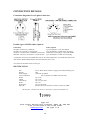
1
NAVIGATOR
DMX Controller
Version 1.2
INSTRUCTION MANUAL
11/5/99
1
DESCRIPTION
The Navigator is a fully programmable controller for DMX intelligent lighting that can be used with
the full range of intelligent lighting fixtures manufactured by Ryger Electronics. It is also possible to
use the Navigator with other manufacturers intelligent lighting by use of a programmable personality
feature. The use of a menu system makes using the Navigator as easy to use as the average mobile
phone. The Navigator has the capability to control 16 different intelligent lighting fixtures of up to 8
DMX channels each and can store up to 128 scenes containing the state of all 16 fixtures. Scenes can
be linked together to form up to 128 different chases consisting of up to 32 steps each. Chases can
also be linked to form up to 16 shows consisting of up to 32 steps each. Scenes, chases and shows can
be recalled manually or by MIDI if the optional MIDI interface has been fitted.
STARTING OUT
The first step is to set up your intelligent lighting fixtures for use with the Navigator. Please note:
The switch settings below apply to intelligent lighting fixtures available from Ryger Electronics. The
procedure for setting the base address for other manufacturers intelligent lighting fixtures may be
different.
Each of the fixtures that the Navigator controls must be set to the correct DMX base address. This is
accomplished by setting the DIP switches on the intelligent lighting fixtures as in the following table:
FIXTURE
NUMBER
1
2
3
4
5
6
7
8
9
10
11
12
13
14
15
16
DMX BASE
ADDRESS
1
1
1
1
1
1
1
1
1
1
1
1
1
1
1
1
1
1
9
17
25
33
41
49
57
65
73
81
89
97
105
113
121
SWITCH
SETTINGS
2 3 4 5 6
0 0 0 0 0
0 0 1 0 0
0 0 0 1 0
0 0 1 1 0
0 0 0 0 1
0 0 1 0 1
0 0 0 1 1
0 0 1 1 1
0 0 0 0 0
0 0 1 0 0
0 0 0 1 0
0 0 1 1 0
0 0 0 0 1
0 0 1 0 1
0 0 0 1 1
0 0 1 1 1
7
0
0
0
0
0
0
0
0
1
1
1
1
1
1
1
1
A 1 in the switch settings column indicates that the switch should be ON, a zero indicates OFF. Any
switches above switch 7 should be placed in the OFF position.
After setting up the individual intelligent lighting fixtures to be used they should be connected one to
another (fixture 1 to fixture 2, fixture 2 to fixture 3, fixture 3 to fixture 4 and so on) with the
appropriate DMX cabling. For TinyScan systems use stereo jack plug to jack plug leads; Defender or
Discovery systems will require the use of cables wired using XLR male to female leads. A long DMX
cable run will require a 100 ohm termination after the last fixture in the chain. Please note that
TinyScans are self terminating and you won’t require the termination if a TinyScan is the last fixture.
It is possible to use a mixture of different intelligent lighting fixtures if cables with XLR plugs/sockets
to jack plugs are used, please see CONNECTION DETAILS and your lighting fixtures manual for
information on connections. Connect each fixture to a source of power. Finally connect the
Navigator to the first intelligent lighting fixture.
2
Connect a 12-25v DC power supply capable of delivering 300mA to the DC input jack of the
Navigator then switch on the power to the lighting fixtures. Switch on the power to the Navigator. On
switch on of the Navigator you will be greeted by the opening screen followed by a message indicating
that the MIDI interface is present if it has been fitted. You will then be given the main menu that
looks like this:
The Navigator has two modes of operation. Programming mode allows the fixtures connected to the
unit to be set up and scenes, chases and shows to be created. Playback Only mode allows saved
scenes, chases and shows to be recalled only; either manually or by MIDI if the optional MIDI
interface has been installed. When the unit is first switched on from new it will power up in Playback
Only mode with scenes and chases for Discovery scanners, Defender Scanners and TinyScan plus
scanners already programmed to get you started. Please go to the Using Playback Only Mode
section of this manual first before you attempt any re-programming of the Navigator.
Please Note: Throughout this manual reference is made to scanner selection keys 1-16 even though
there are 20 scanner selection keys on the Navigator. Scanner selection keys 17 - 20 are reserved for
future development.
FIXTURE SETUP
Using intelligent lighting from the Ryger Electronics range
You must let the Navigator know what type of fixtures are being controlled. To do this select Setup
from the main menu. This will show the setup menu:
From the setup menu select Fixt to set the type of intelligent lighting used on each fixture. At this
point the light above the fixture 1 select key will light to show that fixture 1 is being set up. The
display will change to show the type of the intelligent lighting unit being used by fixture 1, similar to
this:
When the unit is new fixtures 1-4 will be set up for Discovery scanners, 5-8 set up for Defender
scanners and fixtures 9-12 for TinyScan plus units. Pressing the
keys will select the type of
lighting fixture used on fixture 1. You will only need to change the fixture setup if you want to
change the type of lighting unit used on a specific fixture. If you do decide to change fixture settings
this will alter the way that the pre-programmed scenes are recalled - the scenes which use the altered
fixtures will need to be re-programmed to work with the new fixture settings. To alter the lighting
effect used by any fixture press its scanner selection key (the light above the key will light) and repeat
the type selection process. Continue in this way until all fixtures used are assigned the type of
lighting unit to be used. When all fixtures being used have been assigned a type select Quit. You will
be asked if the changed settings should be saved:
3
At this point select Ok to save the fixture settings. After a brief moment you will be informed that the
save operation has been completed and you will be returned to the Setup menu. From the Setup menu
select Quit to return to the main menu.
Using DP40/SP40 MS units
The DP40MS and SP40MS allow DMX base addresses up to 61 only. This means that you can only
use fixtures 1-8 for DP40MS and SP40MS units. You should also note that the DMX base address
selection procedure is different to that outlined in the table above (please see the DP40/SP40MS
manual for details). As the DP40MS and SP40MS units are four channel devices you can place two of
these units on a single fixture by assigning the correct DMX base addresses. For example to set up
two DP40 or SP40 MS units to be used on fixture 1 you would set the first unit to use addresses 1 - 4
and the second unit to use addresses 5 - 8. For fixture 2 the first unit would be set to addresses 9 -12
with the second unit set to addresses 13 - 16. There are no named personalities in the Navigator for
these units - the default fixture type will allow control of both the SP40MS and the DP40MS units.
Using other manufacturers intelligent lighting
It is possible for the Navigator to control intelligent lighting fixtures from manufacturers other than
Ryger Electronics by using the programmable personality feature. To set up a fixture for control of a
type of intelligent lighting not manufactured by Ryger Electronics please use the following steps:
From the main menu select Setup to enter the setup menu:
From the Setup menu select Fixt to set up fixtures:
Select the fixture to be assigned a new type with the 1-16 scanner selection keys and then select a User
type by using the
keys. Next select Edit to change the settings for this type. The Edit menu
will be displayed:
Select Pers to alter the personality settings for the fixture type. The display will look similar to the
following:
Lvl corresponds to the level up/down keys. For example level 1 is power, level 2 is colour and so on
as shown on the front panel of the Navigator. DMX shows the fixtures’ DMX channel that will be
affected by the level key shown by Lvl. The following should help to explain the setup procedure:
The personality settings for a Ryger TinyScan plus are shown below as a guide for setting up other
fixture types:
4
1
2
3
4
5
6
7
8
Level
- Power
- Colour
- Pan
- Tilt
- Gobo
- Rotate
DMX channel
1
2
3
4
5
6
7
8
Step size
1
12
1
1
12
1 (Unused)
1 (Unused)
1 (Unused)
(Joystick X)
(Joystick Y)
(Unused)
(Unused)
(Unused)
Fade or Switch
Switch
Switch
Fade
Fade
Switch
Fade
Fade
Fade
Selecting Lvl steps through the levels 1 to 8. Selecting DMX will step through DMX channels 1-8
that is being controlled by the selected level. For example, the fixture may respond to DMX data on
channel 4 as power; by selecting level 1 (Lvl) and then setting the DMX channel for this level to 4
(DMX) enables the power on DMX channel 4 to be controlled by the level 1 (Power) up and down
keys. In this way the levels for the particular lighting fixture can be set so that the corresponding up
and down keys control the correct DMX channels in the fixture. The ammount that the DMX channel
data is increased or decreased by when the level up and down keys are used can be set by using the
keys; this is shown under “Step”. The value 12 used by the TinyScan Plus for colour and gobo
channels will move the colour wheel by half a step and gobo wheel by a full step so that they may be
accurately positioned during scene programming. For the step size used by other lighting fixtures
please refer to the manufacturers manual.
If the fixture uses X (pan) and Y (tilt) then select Joy to allow the joystick to be assigned to the
fixtures X and Y DMX channels, the display will be similar to this:
A ‘-’ after X or Y indicates that no DMX channel is assigned to the joysticks’ X (Pan) or Y (Tilt)
axis. Selecting X or Y will step through DMX channels 1-8 that the X(Pan) or Y(Tilt) axis of the
joystick is assigned to. Selecting Inv will allow the joystick movement to be inverted for either X or
Y, none or both joystick axes. If a channel has it’s X(Pan) or Y(Tilt) joystick movement inverted this
will be indicated by an ‘i’ after the X or Y channel number. Select Quit to return to personality edit,
then Quit again to return to the Edit menu.
From the Edit menu select Fade, this will allow you to tell the Navigator which levels are to be faded
during a scene crossfade for this fixture type. The display should look something like this:
Normally you should set the levels used for power, pan and tilt to be faded and colour and gobo levels
to switch during a scene fade. Select the appropriate level by selecting Lvl then use Sel to toggle
between fade and switch for this level. Levels not used by the fixture may be set to either option.
Select Quit to return to the Edit menu.
From the Edit menu select Name to change the name from User to something more recognisabe to aid
in identification. You will get a display similar to the following:
The name being changed will be displayed on the second line of the display. Use
to move the
cursor to the character of the name to change and then use the
keys to select the character or
symbol to place into the name. When finished select Quit to return to the Edit menu.
5
From the Edit menu select Quit again. You will be asked if the changes made are to be saved:
Select Ok to save the changes or Quit to abandon the changes. Either way you will be returned to
fixture type selection. If you have saved a new fixture type you may now assign this new type to other
fixtures. Up to 22 custom fixture types may be stored in addition to the pre-programmed fixture types.
PROGRAMMING SCENES
A scene is the state of all the lighting fixtures at a particular time. As an example you may wish to
have several lights directed towards a stage with different colours and/or gobos while a tunnel effect
shows red revolving stars. Each scene must be set up by positioning the individual lights, selecting
colours, gobos, rotation, and any other effects. To do this ensure that you are in the main menu and
select the fixture you wish to set by pressing its scanner selection key. At this point the light above
the key will light and you will receive a brief message stating the fixture type of the selected fixture.
Pressing the level up and down keys will now alter the information sent to the selected lighting
fixture. You will be informed of the data value currently being sent on the selected level for the
selected fixture. Labelled level up and down buttons will affect the aspect of the attached lighting
fixture as described by the labelling, for example pressing the power up key will increase the power
level for the selected fixture while pressing the power down key will reduce the power level (Exactly
how the lighting fixture responds to the power level will be described in it’s manual). To quickly
increase or decrease a level press and hold its up or down key for about 1 second, after which time the
level will be quickly increased or decreased. The other level buttons work in a similar manner
affecting colour, pan, tilt, gobo and rotation. Fixtures that use pan and tilt can also be positioned by
using the joystick. When the joystick is being used the levels for X (Pan) and Y (Tilt) positions are
briefly displayed as the joystick is moved. Repeat the positioning process for all the other fixtures that
you are using by selecting them and altering the levels for the desired effects. Once all fixtures have
been set up you can save the state of all the fixtures as a scene.
To save the scene select Scene from the main menu, this will access the scene menu as shown below:
From the scene menu select Store , the display will show the following:
This is the prompt asking which scene store is to be used to hold the scene. You may select a page
from 1 - 8 in which the scene is to be stored by using the
keys. If there are any scenes already
programmed in the selected page they will be shown by the lights above the scanner selection keys
being dimly lit. At this point it should be noted that already programmed scenes can be overwritten or
deleted without any warning being given. To save the scene, select a scene store from 1 - 16 in the
current page by pressing one of the scanner selection keys. The scene will be saved and a message
informing you that the save has been completed will be given, you will then be returned to the scene
menu. Select Quit to return to the main menu. The process of selecting and altering fixtures to create
more scenes can then be repeated. To delete a stored scene the procedure is the same as storing a
scene except that that you should press and hold the scanner selection key of the scene you wish to
delete for about 1 second; after which the scene will be deleted.
6
Important: Overwriting a scene that is used in any chase or show will alter all occurrences of the
scene in all of the chases or shows that use it. Deleting the scene will not give a blank scene in chases
or shows that use it - only when the scene is re-programmed will the change take effect.
Other functions while programming scenes
Pressing the ‘ALL’ key will select all fixtures making the level buttons affect all of the connected
fixtures simultaneously. If all fixtures are selected then pressing the ‘ALL’ key again will deselect all
fixtures.
Pressing and holding the ‘ALL’ key for about 1 second will clear all fixture outputs and any running
chase or show will be stopped.
Pressing and holding a scanner selection key for about 1 second will clear the selected fixture.
Pressing the ‘JOIN’ key at the same time as selecting a fixture will allow more than one fixture to be
selected at a time. The level buttons will then affect all of the selected fixtures simultaneously.
Pressing the ‘JOIN’ key at the same time as a scanner selection key can also be used to deselect a
fixture without clearing it.
Scenes and fade rate
When a scene is saved it is also saved with a crossfade rate. When the navigator is powered up the
fade rate defaults to 25% which will provide a smooth fade between scenes. It is possible to alter the
crossfade rate for each scene to allow fade or snap between scenes. This is best set once all scenes
have been initially programmed for position and colour. To alter the crossfade rate select Scene from
the main menu, this will access the scene menu as before:
Programmed scenes in the current page are shown by dimly lit lights above the scanner selection keys.
The scene page may be selected by using the
keys. Press the fixture key of the scene you wish
to recall. Your lighting fixtures will move to position themselves to the settings for the selected scene,
the rate at which they do this is determined by the scene crossfade rate. To change the rate, select
Fade and use the
keys to alter the fade rate. A fade rate of 0% will cause the scenes to be
instantly switched to; other fade rates will produce fades between scenes of varying rates (1% = fast
fade, 100% = slow fade). To see the effect of the new fade rate you must select another scene and then
re - select the scene that you wish to alter the fade rate for. Selecting off will clear all of the attached
lighting fixtures in the same way as pressing and holding the ‘ALL’ key. Once you are happy with
the fade rate for the scene select Quit to return to the scene menu then use Store to re - save the scene
with the new fade rate. To aid in this process the scene last recalled will be indicated by a brightly lit
light above the scanner selection keys when you are prompted for the scene to store to. If the lighting
fixtures are in the process of changing state it is important to wait until the final positions have been
reached before saving to avoid the intermediate state being inadvertantly saved. Please note that
while in programming mode all scenes will be recalled with the crossfade rate set from the scene fade
setting as described above. Only in Playback Only mode, or when previewing chases or shows, will
scenes be recalled with their stored fade rates.
Changing a previously stored scene
The process to change a scene is very similar to changing the fade rate. From the main menu select
keys and select
Scene and recall the scene you wish to edit by setting the scene page with the
the scene from the page with the 1-16 scanner selection keys (available scenes will be shown by dimly
lit lights above the scanner selection keys). Once the scene to edit has been recalled, select Quit to
return to the main menu. Alter any fixtures by selecting the fixture with scanner selection keys 1-16
and then use the level up and down keys and/or joystick to adjust as before. Once the scene has been
7
altered it may be re-saved to the same scene store or to another scene store by selecting Scene from
the main menu followed by Store. As an aid to this, the last recalled scene will be indicated by a
brightly lit light above the scanner selection keys when you are prompted for the scene to store to. It
should be noted that a scene can also be copied to another scene store by recalling the scene and then
re-saving it to a different scene store.
PROGRAMMING CHASES
A chase consists of a sequence of scenes. The Navigator can store up to 128 different chases
consisting of up to 32 steps each. There must already be scenes programmed before a chase can be
programmed.
From the main menu select Chase to access the chase menu as shown below:
Select Opt to go to the chase options menu:
Select PGM by pressing and holding its button until the chase programming display appears.
Holding the button will clear the chase programming buffer, allowing a new chase to be programmed.
The chase programming display should look like this:
The asterisk ( * ) indicates that there are no chase steps currently stored in the chase being
programmed. To select a scene to add to the chase, press the button next to P1-S to step through the
scene pages (1-8) and select a scene by using the scanner selection keys 1-16. Available scenes will be
shown by dimly lit lights above the scanner selection keys. The currently selected scene will be
indicated by a brightly lit light above the fixture keys. The selected scene page is indicated after the
‘P’ on the display, the scene number within the page is shown after the ‘S’. The lighting fixtures will
move to take up their positions for the selected scene. To add the scene to the chase select Add; the
selected scene will be added at the end of the chase and the step number will be adjusted accordingly.
Repeat the selecting and adding
process for the number of desired steps. To see which scenes have been used in the chase, use the
keys to increase or decrease the step number and view the scene making up the selected step.
If you wish to delete a step, select the step to remove and select Del. When you are happy with all the
steps of the chase select Quit to return to the chase options menu. To preview the programmed chase
select Run, the programmed chase will start running. You may now alter the hold setting for the
chase by selecting Hold and using the
keys to alter the value from 0% to 99%. The hold value
determines the time each step of the chase is active for before moving to the next step, its default value
on power up is 20%.
If you need to delete a step or add steps to your chase then select PGM from the chase options menu
but without holding the button down, this will allow alteration of the steps forming the chase. After
any changes have been made you may return to the chase options menu by selecting Quit and preview
the chase by selecting Run as before.
To save the chase select Store, the display will change to show:
8
This is the prompt asking which chase store is to be used to hold the chase. You may select a page
from 1 - 8 in which the chase is to be stored by using the
keys. If there are any chases already
programmed in the selected page they will be shown by the lights above the scanner selection keys
being dimly lit. At this point it should be noted that already programmed chases can be overwritten or
deleted without any warning being given. To save the chase, select a chase store in the current page
by pressing one of the scanner selection keys 1-16. The chase will be saved and a message informing
you that the save has been completed will be given, you will then be returned to the chase options
menu. You may then program and save more chases in the same way as described above. To delete a
stored chase the procedure is the same as for storing a chase except that that you should press and
hold the scanner selection key of the chase you wish to delete for about 1 second, after which the
chase will be deleted.
Important: Overwriting a chase that is used in any show(s) will alter all occurrences of the chase in
all of the shows that use it.
Changing a previously stored chase
To make changes to a previously stored chase select Chase from the main menu. This will take you to
the chase menu:
Use the
keys to select the chase page and then select the chase to change by using the scanner
selection keys 1-16 (available chases are shown by dimly lit lights above the scanner selection keys).
The selected chase will now run. Select Opt to reveal the chase options menu and then select PGM
but without holding the button down. You may now alter which scenes make up the chase and adjust
the hold value for the chase. When the chase has been changed to your liking it can be re-saved to the
same chase store or a different chase store as described above. As and aid to replacment, the last chase
recalled will be indicated by a brightly lit light above the scanner selection keys when you are
prompted for the chase to store to. A chase can be copied by recalling the chase and then re-saving it
to a different chase store in the same way that a scene can be copied.
Selecting Stop in the chase menu will stop a running chase, allowing the current fixture state to be
saved as another scene if desired.
PROGRAMMING SHOWS
A show consists of a sequence of chases. The Navigator can store up to 16 different shows consisting
of up to 32 steps each, where each step is a chase also up to 32 steps in length. In effect a show is an
extended chase.
From the main menu select Show to access the show menu as shown below:
Select PGM by pressing and holding its button until the show programming display appears.
Holding the button will clear the show programming store, allowing a fresh show to be programmed.
The show programming display is almost identical to the chase programming display and should look
like this:
9
The asterisk ( * ) indicates that there are currently no steps in the show being programmed. To select
a chase to add to the show, press the button next to P1-C to step through the chase pages (1-8) and
select a chase by using the scanner selection keys 1-16. Available chases will be shown by dimly lit
lights above the scanner selection keys. The currently selected chase will be indicated by a brightly lit
light above the fixture keys. The selected chase page is indicated after the ‘P’ on the display, the
chase number within the page is shown after the ‘C’. The selected chase will begin running allowing
a visual check that the required chase has been selected. To add the chase to the show select Add; the
selected chase will be added at the end of the show and the step number will be adjusted accordingly.
Repeat the selecting and adding process for the number of desired steps. To see which chases have
been used in the show, use the
keys to increase or decrease the step number and view the chase
making up the selected step. If you wish to delete a step, select the step to remove and select Del.
When you are happy with all the steps of the show select Quit to return to the show menu. To preview
the programmed show select Run, the programmed show will start running.
If you need to delete a step or add steps to your show then select PGM from the show menu but
without holding the button down, this will allow alteration of the steps forming the show. After any
changes have been made you may return to the show menu by selecting Quit and preview the show by
selecting Run as before.
To save the show select Store, the display will change to show:
This is the prompt asking which show store is to be used to hold the show. If there are any shows
already programmed they will be shown by the lights above the scanner selection keys being dimly lit.
At this point it should be noted that already programmed shows can be overwritten or deleted without
any warning being given. To save the show , select a show store by pressing one of the scanner
selection keys 1 - 16. The show will be saved and a message informing you that the save has been
completed will be given, you will then be returned to the show menu. You may then program and
save more show in the same way as described above. To delete a stored show the procedure is the
same as for storing a show except that that you should press and hold the scanner selection key of the
show you wish to delete for about 1 second, after which the show will be deleted.
Changing a previously stored show
To make changes to a previously stored show select Show from the main menu. This will take you to
the show menu:
Select the show to change by using the scanner selection keys 1 - 16 (available shows are shown by
dimly lit lights above the scanner selection keys). The selected show will now start to run. Select
PGM but without holding the button down. You may now alter the which chases make up the show.
When the show has been changed to your liking it can be re-saved to the same show store or a
different show store as described above. As and aid to replacment, the last show recalled will be
indicated by a brightly lit light above the scanner selection keys when you are prompted for the show
to store to. A show can be copied by recalling the show and then re-saving it to a different show store.
Selecting Stop from the show menu will stop a running show, allowing the current fixture state to be
saved as another scene if desired.
10
ACTIVATING PLAYBACK ONLY MODE
Once the Navigator has been programmed with all the scenes, chases and shows to be used it will be
necessary to activate the Playback Only mode of the unit. This will prevent alteration of stored
information and allow the MIDI interface to function if fitted. It is still possible to enter the
programming mode if any changes need to be made to stored scenes, chases or shows but you will
need to enter a passcode to do this. Please read the following carefully.
NOTE: IF THE PASSCODE IS FORGOTTEN THEN THERE IS NO WAY TO GET THE UNIT
BACK INTO PROGRAMMING MODE ONCE LOCK HAS BEEN SELECTED
Should this happen please contact Ryger Electronics for assistance.
To activate Playback Only mode select Setup from the main menu and then from the setup menu
select Lock. The following options will be presented:
Quit - Selecting Quit returns to the Setup menu.
Lock - You should only select this option when all of the scenes, chases and shows going to be used
have been programmed. Selecting this option will lock the Navigator and convert operation to
Playback Only mode. After lock has been selected the Navigator will always power up in Playback
Only mode unless Unlock is later selected. To re-enter Programming mode a passcode needs to be
entered. The default passcode is 1-2-3-4; this can be changed by selecting the NewCode option.
NewCode - This allows the passcode to enter Programming mode to be changed. When selected you
will be prompted to enter a new passcode as shown below:
You may now enter up to 8 digits for the passcode by using the scanner selection keys. Select Enter to
accept the new passcode. The new passcode will be saved and then you will be returned to the
previous menu.
Unlock - Selecting this option will make the Navigator power up in Programming mode again.
USING PLAYBACK ONLY MODE
Once the Navigator has been locked, playback only mode will be active. The display will change to
display the following once Lock has been selected and whenever the unit is powered up:
StBy - This option places all of the connected lighting fixtures into standby state. All of the connected
lighting fixtures will have their power level set to zero and any running chase or show will be stopped.
To come out of standby and continue, select StBy again or select a new scene, chase or show.
Scene / Chase / Show - This option will change the recall mode of the Navigator between recall of
scenes, chases or shows. The display will change to show the current recall mode. Dimly lit lights
above the scanner selection keys indicate which scenes, chases or shows are available in the current
11
page. The scene or chase page can be selected by the
keys. For shows there is only one page,
the
keys will have no effect in the show selecting mode.
Auto / Sound - This option will toggle between automatic and sound mode for recalled chases and
shows. In Auto mode a chase will play back with it’s stored hold setting making the time between
chase steps equal. In Sound mode the chase will advance a step when a bass beat is detected by the
internal microphone.
Setup - This option will allow access to the Programming mode of the Navigator. You will be
prompted to enter the passcode before access to the programming mode is allowed. Upon entry of the
correct passcode the Navigator will be temporarily unlocked allowing reprogramming or storage of
more scenes, chases or shows.
Recall of scenes, chases and shows in playback only mode
To recall a scene, chase or show, select the appropriate recall mode. Select the page with the
keys (Scenes and Chases only). Pressing a scanner selection key with a dimly lit light will instantly
recall the stored scene, chase or show. The light will change from dimly lit to brightly lit to show the
selection has been made.
With the optional MIDI interface installed inside the Navigator, all of the Playback Only functions
can be accessed by sending MIDI notes to the Navigator. Please see the Navigator MIDI interface
supplement for more information.
Pre-programmed scenes and chases
When the Navigator is new there are some scenes and chases already programmed to get you started:
Scene and Chase page 1 is used for Discovery Scanners using fixtures 1 - 4
Scene and Chase page 2 is used for Defender Scanners using fixtures 5 - 8
Scene and Chase page 3 is used for TinyScan Plus scanners using fixtures 9 - 12
Please note: It is possible to overwrite this pre-stored information. If you do decide to do this there is
no way to get the information back.
12
RESTORING DEFAULT SETTINGS
From the Setup menu there is an option, init, which allows certain aspects of the Navigator to be reset
to their default settings. This option should be used with extreme care as it’s effects are irreversable.
A description of the options will be given below.
From the main menu select Setup to enter the Setup menu and then Select Init. The following options
will be given:
Fixpers - Selecting this option will remove any changes made to the pre - stored Ryger fixture types
after confirmation.
Userprs - Selecting this option will remove any changes made to the User personalities and reset all
User personalities to their default settings. ANY CUSTOM FIXTURE TYPES THAT HAVE BEEN
PROGRAMMED WILL BE LOST. You will be asked for confirmation before the operation is carried
out.
All - WARNING Selecting this option will ERASE ALL DATA PROGRAMMED INTO THE
NAVIGATOR INCLUDING THE PRE-PROGRAMMED SCENES AND CHASES AND RETURN
IT TO A BLANK STATE. You are asked for confirmation before the operation is carried out.
13
CONNECTION DETAILS
Connection diagrams for rear panel connectors
Possible types of DMX cables required
Connection
Navigator to Discovery / Defender
Navigator to TinyScan / TinyScan Plus
TinyScan / TinyScan plus to Defender or Discovery
Defender / Discovery to TinyScan / TinyScan Plus
Cable required
3 pin XLR male to 3 pin XLR female
3 pin XLR male to 2.5mm Stereo Jack plug
2.5mm Stereo Jack plug to 3 pin XLR female
3 pin XLR male to 2.5mm stero Jack plug
A terminator for the end of a DMX cable run can be constructed from a 3 pin XLR male with a 100
ohm resistor (Brown Black Brown) connected between pins 2 and 3
All connectors should be of the in-line type.
SPECIFICATION
Size
Weight
Power Supply
Control Channels
Scenes
Chases
Chase Steps
Shows
Show Steps
Optional
4U 19” Rack mount 70mm or sloping front desk mounting case
3Kg
12-25Vdc @ 300mA
128 (16 fixtures of 8 DMX channels each)
Up to 128
Up to 128
Up to 32 per chase
Up to 16
Up to 32 per show
Interface for recall of Scenes, Chases or shows by MIDI
The Navigator conforms to EN 60730-2-1, EN 60335-1, EN50 082 and EN55 014
!1999
Ryger Ltd
Feidr Castell Business Park, Fishguard, Pembs, UK, SA65 9BB
T:+44 (0)1348 875387 F:+44 (0)1348 874963
[email protected]
www.ryger.co.uk
14
15