1
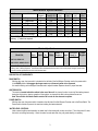
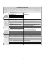
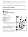
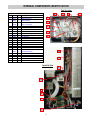
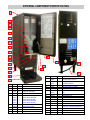
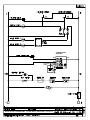
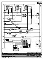
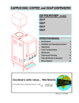
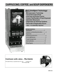
Compact Cappuccino &
Hot Chocolate Dispensers
Models:
•GB1CP
•GB2CP
•GB3CP
•GB1HC-CP
•GB2HC-CP
•GB1HC-CP-PC*
•GB2HC-CP-PC*
GB1HC-CP (shown)
GB2-CP (shown)
Cecilware sells value... Worldwide
45 -05 20th Avenue, Long Island City, NY 11105
Tel: 1-718-932-1414
1-800-935-2211
Fax:
1-718-932-7860
E-mail: [email protected]
OPERATIONAL MANUAL
NL05A May 2007
Mechanical Specifications
Model #
Label
No. of
Hopper
Width
Depth
Height
Hoppers Capacity (lb.)
(in.)
(in.)
(in.)
GB1CP
Cappuccino
1
8 lb.
7.75
19
27
GB2CP
Cappuccino
2
4 lb.
7.75
19
27
GB3CP
Cappuccino
3
4 lb.
9.88
19
27
GB1HC-CP
Hot Chocolate
1
8 lb.
7.75
19
27
GB2HC-CP
Hot Chocolate
2
4 lb.
7.75
19
27
GB1HC-CP-PC
Hot Chocolate
1
8 lb.
7.75
19
27
GB2HC-CP-PC
Hot Chocolate
2
4 lb.
7.75
19
27
Add an additional 2.5” when installing with legs. Add 2" for line cord and valve fitting clearance.
Plumbing: ¼” water line required.
Tank
(Gal.)
2
2
2
2
2
2
2
Electrical Specifications
Model No.
GB1CP, GB2CP, GB3CP
Volts Phase Hz
Watts
120V
1
50/60 1.8KW
Number of
Receptacle Circuit
Heaters Amps Nema No. Breaker
1
15
5-15R
15A
GB1HC-CP, GB2HC-CP
GB1HC-CP-PC*,•GB2HC-CP-PC*
* Automatic Portion Control
For Wiring, refer to Wiring Diagrams. See Electrical Data Label attached to the back of the unit for proper voltages, breaker sizes
and electrical outlet requirements for each model number listed.
DESCRIPTION OF COMPONENTS:
RINSE SWITCH.
With the door open, the rinse switch is located on the left side of the first Whipper Chamber next to the power switch.
In the RINSE position it disengages the hopper motors and allows only water to be dispensed.
It is used for flushing out the Whipper Chambers and to adjust the water dispense valves for proper flow rates.
HEATER SWITCH.
This switch is located behind the cabinet in the rear of the unit.. Its primary function is to shut off the heating element
during the initial priming, start up operation of the machine, or whenever the tank is being drained for service.
Note: Power Switch and Heater Switch must be ON in order for the elements to operate.
POWER SWITCH.
With the door open, the power switch is located on the left side of the first Whipper Chamber next to the Rinse Switch. The
Power Switch controls all power to the machine including the heater elements.
WATER LEVEL CONTROLS.
Under normal conditions and operation, the water level in the tank should not drop more than ½" from the probe. If it does,
the tank is not refilling fast enough. Check the water line and water filter, they may need cleaning or replacing.
2
I. INSTALLATION INSTRUCTIONS
This equipment is to be installed to comply with the applicable Federal, State, or local plumbing codes having jurisdiction.
In addition:
1. A quick disconnect water connection or enough extra coiled tubing (at least 2x the depth of the unit) so that the machine
can be moved for cleaning underneath.
2. An approved back flow prevention device, such as a double check valve to be installed between the machine and the
water supply.
The GB beverage dispenser is equipped with a ¼" Flare Water Inlet Fitting which is located on the left side in the back of the
base (when looking at the machine from the front).
HIGHLY RECOMMENDED: A WATER SHUT-OFF VALVE and A WATER FILTER, preferably a combination
Charcoal/Phosphate Filter, to remove odors and inhibit lime and scale build up in the machine.
Note: In areas with extremely hard water, a water softener must be installed in order to prevent a malfunctioning of the
equipment and in order not to void the warranty.
After the machine has been unpacked and placed on a counter, pull out the stainless steel drip tray.
It should contain the following: A Set of 4 Adjustable Leveling Legs & Water Inlet Fitting.
II. START UP INSTRUCTIONS
Caution: Make sure that the Heater Switch, located behind right hopper with door opened, is in the OFF position.
1. Connect the ¼" dia. copper waterline to the ¼" flare water inlet fitting of the valve.
2. Plug the power cord into a proper receptacle.
3. Activate the Power Switch (Toggle Up). The red power indicator light and the green dispense buttons will light up and the
tank will start filling. Allow approximately 4-5 minutes for the tank to fill.
4. Activate the Heater Switch. Allow approximately 10-30 minutes for the water to reach a temperature of 195°F. The heat
up time will depend on the water inlet temperature, the input voltage and the wattage of the elements in the machine.
5. Place a 6 oz. or larger cup under the left dispense nozzle, press and hold the left dispense switch for 6 seconds. The
machine will dispense water at the rate of 1 oz. per second. Repeat it several times to check for consistent output. Repeat
same for the other dispense switches. This procedure checks that the dispense valves are not air-locked.
6. While the tank is heating up, remove the hoppers, load them with products and reposition them back in the machine.
When the green ready light comes on, the tank has reached its brew temperature and the machine is ready to dispense
the first cup of Cappuccino.
To Dispense a Cup of Cappuccino: Place a 8 oz. or larger cup under selected drink dispense nozzle.
For Manual units: Push and hold brew button until cup is 2/3 full, then release button.
For Automatic units: Press and Release button. Cup will fill up automatically to it’s preset amount.
See Drink Strength Adjustments if different levels of drink strength are desired or Programming Dispense Volume if
different cup sizes are used.
3
ADJUSTMENTS
A. WATER FLOW ADJUSTMENTS, FLOW RATE
The Unit Is Factory Adjusted To Dispense Water At The Rate of 1 to 1.3 oz/ sec.
To increase or decrease flow, proceed as follows:
1. Remove Left side panel and locate Dispense Valve mounted on tank, with Flow
Adjuster facing up, underneath cold water reservoir.
2. Locate Flow Adjustment Screw (white) on Dispense Valve. Use Allan Key to
reach Flow Adjuster.
3. Rotate Adjustment Screw Counterclockwise to INCREASE flow rate.
4. Rotate Clockwise to DECREASE flow rate.
When making adjustments, do not adjust by more than 1/4 turn at a time,
without checking output flow or drink strength (ratio of water to powder).
WATER FLOW ADJUSTMENT
DISPENSE VALVE
The Dispense Valve is factory adjusted for a maximum flow rate of 1 to 1.3 oz/ sec. for coffee or cappuccino.
Exceeding 1.3 oz / sec Flow Rate will cause the Mixing Chamber to overflow.
To Check Volume And Gram Throw Dispensed (ratio):
1. Remove the product guide from the hopper and position a receptacle under the hopper nozzle to catch the gram throw of
product. Also place a measuring cup under extension tube to catch the water dispensed.
2. Push the dispense button and check the amount of product dispensed, amount of water dispensed, and time [use stop
watch] to dispense that water.
3. The amount of water dispensed in the measuring cup divided by the amount of time to dispense that water is the Water
Flow Rate from Dispense Valve.
For Cappuccino:The machine is factory adjusted to dispense 4.5-5.0g / sec. per 1oz. of water [36-40g Product per 8 oz. cup]
MAINTENANCE
RECOMMENDED PREVENTIVE MAINTENANCE
1. Check All Chamber Mounts For Signs Of Wear
A. Product Running Down The Front Of The Unit.
B. Product Built Up On The Back Of Chamber Mount.
Remove Chamber Mount.
Clean And Re-Lubricate Motor Shaft
Using Food Grade Lubricant Only .
Replace With New Chamber Mount.
2. Clean Out Vent Motor, Trough And Tubing.
Lift up black tabs, remove Trough Drawer,
Clean, and replace Trough Drawer.
Remove Hose Assembly From The Motor.
Clean Out And Replace.
3) Check All Dispense Valves For Lime Build-Up.
Drain The Water Tank To Just Below The Level Of The Dispense Valves.
Remove The Valves And Clean.
( You Can Take These Valves Apart By Hand As Shown).
Replace The Assembly As Needed.
Replace The Valve Into The Tank And Refill tank.
WATER FLOW ADJUSTMENT
4
COMPONENTS TEST
A) Thermostat Adjustments:
The Thermostat is factory set for proper dispense temperature
of 190° F with the control shaft set to the maximum clockwise position. If field
adjustments are needed proceed as follows:
To DECREASE temperature, turn the control shaft slightly in the
COUNTERCLOCKWISE direction.
For qualified technicians ONLY:
Remove the knob and locate the Slotted Adjustment Screw inside the hollow
thermostat shaft. Using a narrow-bladed screwdriver, engage slotted adjustment
screw and turn it ¼ turn very slowly counterclockwise (CCW). Allow a few minutes
for the temperature to reach set level. The Heater Light will go ON, indicating the
heating element is activated, wait for it to go OFF, indicating that the water has
reached NEW set temperature. Take a temperature reading and repeat if necessary.
B) Water Inlet Valve Test
Turn power OFF. If the water level rises inside a partially filled tank, the Water
Inlet Valve is leaking. Disconnect wires from the Water Inlet Valve coil and
connect a 2 wire line cord to the terminals. Plug it into a 115V outlet. If water
flows in and stops when you pull it out, the Valve is working fine. Repeat this test
a few times. The problem may be in the Probe or Water Level Control Board. If
the water does not flow in when the cord is plugged into an electrical outlet, the
Solenoid coil may be damaged, opened, or the valve may have an obstruction
preventing the water from flowing in. Clean or replace it.
C) Dual Probe Test
If lack of water persists, first check incoming water flow rate, if flow rate is OK
proceed as follows:
Turn on the power and water supply. Check inside the tank to make sure the water is
below the Probe. Pull the BLUE wire and terminal OFF the Probe rod. If water still
does not flow after the wire is disconnected from the Probe, the problem may be in
the Solid State Dual Level Control Board.
If water starts flowing into the tank, the Probe may be grounded, due to excessive
liming. Check with Ohm meter. Clean or replace probe.
D) Dual Probe Liquid Level Controller Bench Test
Check the Controller as follows:
1. Make sure there is power input to the Controller at the terminals AC1 &
AC2
Your voltmeter should read 115 Volts. It should read the same at terminals
AC1 & FILL when the water level is low. This is the output power to actuate
the coil of the Solenoid Valve to open it. The lack of voltage at terminals AC1
& L-LEVEL or H-LEVEL indicates that the Controller is not working properly.
2. Make sure all wire connections are tight, including ground.
3. If after this, the Controller is still failing to open the Water Inlet Valve,
replace it.
5
TROUBLESHOOTING GUIDE
WARNING: To reduce the risk of electrical shock unplug the dispenser power cord before repairing or replacing
any internal components of the unit.. Before any attempt to replace a component be sure to check all electrical
connections for proper contact.
PROBLEM
PROBABLE CAUSE
REMEDY
1
A Water supply OFF.
Turn water ON.
No water
B Clogged inlet screen (Water Inlet Valve). Disconnect water line and clean inlet screen.
when Rinse C Inoperative Water Inlet Valve.
Check connection, if needed replace Valve.
Switch is ON. D Loose electrical connection at level
Check all electrical connections. at water level
control probe or board.
controls.
2
A No product in Hopper.
Add product.
No product B Auger not working.
Engage Hopper/Nut to Motor Gear (See section VI).
when
C Damaged, loose, or missing Agitator
Replace Agitator/Auger Gear (See section VI).
Dispense
Gear.
Button is
D Inoperative Auger Motor or Relay.
Check connections of Motor, Relay and/or Switch,
pressed
if needed replace components.
E Hopper outlet clogged
Clean Hopper and check Cartridge Heater.
F Faulty Coupling.
Replace damaged Coupling components.
3
A Clogged/stuck Water Dispense Valve Clean or unclog Water Dispense Valve.
Water does
Replace Dispense Valve if inoperative.
not shut off.
Water keeps
dispensing.
4
A Heater Switch is OFF.
Water is not B Thermostat is OFF.
heating up in C Loose connection on Thermostat.
the tank.
D Bad Thermostat
E Hi-Limit Temperature Switch is defective
F Heater is burned out or defective.
Turn Heater Switch ON.
Turn Thermostat ON. Turn Knob Clockwise.
Make sure all wires and terminals on Thermostat are
tight.
Replace the thermostat.
Replace the Hi-limit.
Replace the Heater.
6
CLEANING AND SANITIZING
Sanitizing: All sanitizing agents in the food zone must comply with 21 CFR 178.1010.
All food dispensing units should be sanitized periodically. All parts to be sanitized must be cleaned first.
To prepare a sanitizing solution:
Add 2 Tsp. Of Liquid Clorox Bleach (5.25% Concentration) To 1 gallon Of Water At Room Temperature (70°- 90°F).
Note: Always start with a unopened bottle of Clorox Bleach since the solution from an opened bottle has a short life span.
• Soak all parts for a minimum of 3 min. in the sanitizing solution.
• Let all sanitized parts drain and dry naturally. DO NOT WIPE THEM DRY.
• Before using the sanitized unit (or parts) with food stuffs, rinse all parts thoroughly with water.
Water pipe connecting and fixtures directly connected to a potable water supply shall be sized, installed, and maintained in accordance with
Federal, Sate, and Local codes-section 7.
Cleaning
1. Turn the power switch to OFF.
2. Remove the drip tray with grill and empty the contents.
3. Wash and let dry the tray and grill (use a mild dishwasher detergent).
4. Wash and let dry the dispense area.
5. Turn the power switch to ON.
Cleaning the Hoppers
1. Remove the hopper from of the cabinet.
2. Pull off the elbow chute and remove the hopper cover.
3. Unscrew the rear auger nut and pull out the auger, agitator wheel, and spring.
4. Follow the cleaning and sanitizing procedure above.
5. Let dry all items and reassemble in reverse order.
Filling the Hoppers
1. Remove Hopper from cabinet
2. Fill each hopper with the correct product.
3. Reposition hoppers in the hopper compartment, making sure the hoppers are
properly seated.
Flushing the Whipper Chamber
1. Open the cabinet door and turn the RINSE switch to ON.
2. Place a container under the dispense nozzle and push the dispense switches.
Note: On manual dispense machines, push and hold the dispense buttons
for 10 seconds.
3. Turn the Rinse switch back to OFF.
4. Remove the drip tray, wash and let dry thoroughly.
Removing and Cleaning the Whipper Chambers
1. Remove the dispense cap by pulling it forward and at the same time twisting
it clockwise.
2. Grab and pull the mixing bowl out of the mixing bowl socket.
3. Grab and twist the whipping chamber clockwise and pull it off the mounting
plate.
4. Pull the Whipper blade off the motor shaft.
Notice the flat keyways on the motor shaft and the matching keyways on
the Whipper Blade shaft.
It is important that these keyways are lined up when re-assembling the components.
5. Twist the mounting plate clockwise and pull it off the motor shaft.
6. Slip off the o-ring from the Whipper chamber mounting plate and clean o-ring
and o-ring seat.
7
INTERNAL COMPONENTS IDENTIFICATION
Tank Top View
TANK ASSEMBLY SK89Q
ITEM P/N
QTY DESCRIPTION
1 SK88A
1 Tank Top
2 L681A
1 Thermostat & Probe
M008A
1 Thermostat Knob
3 G267A
1 Heater 120v 1700w
MO18A
1 Gasket, Tank Heater
4 P446A
4 1/4-20x5/8 SS SL Hex Washer Hd Scr
5 M461A
6 Silicone Seal (.466 Id)
6 K525A
3 Elbow 90° Ss
7 M326A 23” Hose - Overflow
8 K695Q
1 Dual Probe Sub-Assy
9 L573A
1 Hi-Limit 220° F
10 SK89A
1 Tank Weldment
11 L467A
1 Dispense Valve
12 M324A
6” Hose to Dispense Valve
13 CD175
1 Auger Motor
14 CD350
1 Whipper Motor
15 CD56A
1 Suction Fan
16 L690A
1 Dual Level Control Hi-Lo
17 CD257
1 Inlet Valve 110V
K491B
1 Water Inlet Connector
3
4
5
6
7
8
9
10
11
Open Side View
13
14
15
16
17
8
5
2
1
EXTERNAL COMPONENTS IDENTIFICATION
1
2
3
4
5
6
7
8
9
10
19
11
20
12
22
18
13
17
14
21
15
ITEM
10
16
11
ITEM
1
2
3
4
5
6
7
8
9
P/N
SS42A
SS51A
CD161
CD155
M705A
CD70A
CD234
CD246
CD374
CD373
CD61A
CD254
CD67A
CD137
CD124
QTY
1
2
1
2/3
1
1
1
1
1
1
1
1
1
1
1
DESCRIPTION
Top Cover
Side Panels
Hopper 8lb GB1
Hopper 4lb GB2, GB3
Door Latch
Product Guide GB1, GB3
Product Guide Right GB2
Product Guide Left GB2
Product Guide Right GB3
Product Guide Left GB3
Steam Deflector GB1, GB2
Steam Deflector GB3
Mix Bowl Socket
Mixing Chamber
Slinger Disk
12
13
14
15
16
17
18
19
20
21
22
P/N
CD65A
CD66A
CD63A
CD353
M884A
C002A
M172S
75014
75015
RE73A
SS46A
K618A
SS49A
SS48A
C032S
L069A
L735A
L299A
K178A
9
QTY
1
2
1
1
1
1
1
1
1
1
1
2
1
1
1
1
1
1/2/3
1
1
DESCRIPTION
Chamber Mount
Chamber Mount Grommet
Whipping Chamber
Whip Blade W/2flats
Extension Tube
Pilot Light Amber, for heater
Legs 4"Adj (Set Of 4)
Molded Drip Tray
Grill
Drip Tray Platform
Facia Bottom Cap
Hidden Hinge S/S
Inside Door Panel
Door Housing
Line Cord
Heater Switch in Back of Machine
Power Sw. in Hopper Compartment
Dispense Switch, on Front Door
Rinse Switch in Hopper Compartment
Hose Nut Ass’y [not shown]
- WATER LEVEL
CONTROL -
RED
WHT
BLU
WATER LEVEL
PROBES
WATER
FAN
CECILWARE CORPORATION
YEL
GRN
BLK
- WATER LEVEL
CONTROL -
RED
WHT
BLU
WATER LEVEL
PROBES
WATER
FAN
CECILWARE CORPORATION
YEL
GRN
BLK
WATER INLET
VALVE
RED
LIQUID LEVEL CONTROL
WHT
WATER LEVEL
PROBES
BLU
YEL
GRN
WATER
CECILWARE CORPORATION
BLK