1
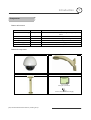
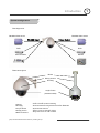
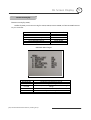
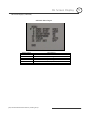
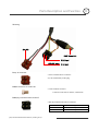
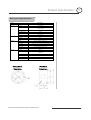
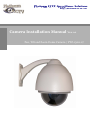
Platinum CCTV Surveillance Solutions http://Platinum-CCTV.com http://Platinum-CCTV.com Camera Installation Manual Ver 1.0 Pan, Tilt and Zoom Dome Camera / PTZ-1500-27 ○1 Introduction Features 3 Components 4 System Configuration 5 2 Installation ○ Wall Mount 6 Ceiling Mount 7 Final Assembly 8 3 Camera Addressing ○ Camera Address Setting 9 Protocol and Baud Rate Settings 11 4 Advanced Features ○ Auto Scan 12 Camera Power 12 Back Light Compensation 12 ICR 12 Digital Zoom 13 Focus Mode 13 Iris Mode 13 White Balance Mode 13 Auto Cruise 13 5 On Screen Display ○ Main Menu 14 Focus Set 15 Auto White Balance 15 Auto Exposure 16 Special Functions 16 Motion Detection 17 Function On Screen Display 17 6 Parts Description and Function ○ 18 ○7 Product Specifications 19 Pan, Tilt and Zoom Dome Camera / PTZ-1500-27 2 Introduction 1 Features Camera Specification • Sony Module 480 Lines • .2 Lux (Color Operation) • 27X Optical Zoom • 10X Digital Zoom • Total Zoom 270X • 24v AC Complete View • 360 Degree Pan, 90 Degree Tilt. For No Blind Spots Housing • Indoor / Outdoor use, Weather Proof Housing. • Multiple Mounting Configurations. • Operating Temperatures: 0 Deg. C ~ 40 Deg. C PTZ Control • RS-485 Communication, MAX 256 Multi-drop • Versatile Pelco-D and Pelco P Protocol • Variable Pan and Tilt Speed • 64 Programmable Presets • OSD Setup • Up to 6 Programmable Cruise Sequences Pan, Tilt and Zoom Dome Camera / PTZ-1500-27 3 Introduction 1 Components Parts Information Item Dome Camera and Housing Part No. PTZ-1500-27 Description NTSC Dome Camera, Weather Proof Housing, Including Transparent Dome Wall Mount Bracket Bracket for mounting PTZ to Wall Ceiling Mount Bracket Bracket for mounting PTZ to Ceiling Mounting Screws & Wrench Allen Screws for mounting PTZ to Mount Power Supply 24v AC Power Supply Manual Manual for ACD-1500-C22 Default Components Dome Camera and Housing Wall Mount Bracket Ceiling Mounting Bracket Accessories Manual PTZ-1500-27 Manual Screws, Wrench and Power Supply Pan, Tilt and Zoom Dome Camera / PTZ-1500-27 4 INTRODUCTION Introduction 1 System Configuration Configuration BlueNet Video server BlueNet Video server RS-485 Input Video Output DVR DVR PTZ Controller Monitor Part Description Mount Wiring Access Housing Acrylic Dome (Camera inside) • Mount • Housing • Acrylic Dome • Wiring Access • Built in Heaters Used to install Camera Housing Protects Internal Components From the Elements Protects PTZ Camera Allows access to internal wiring Keeps lens clear in cold weather Pan, Tilt and Zoom Dome Camera / PTZ-1500-27 5 INSTALLATION Installation 2 System Installation Wall Mount Installation using Outdoor Housing Assembly 1) Attach the Wall Mount Bracket to the wall. Make sure the wall can support the weight and vibration of the camera and housing. 2) Remove thumb screw holding access cover in place on Mounting Arm. 3) Route the wiring through the inside of the arm and out the access hole. 4) Assemble and screw the Outdoor Housing Assembly on the Mount Bracket while routing the wiring from the camera through the neck of the bracket and out the access hole. Continue to page 8 Pan, Tilt and Zoom Dome Camera / PTZ-1500-27 6 Installation INSTALLATION 2 Ceiling Mount Installation using Outdoor Housing Assembly 1) Mount the Top Ceiling Mount Bracket to the Ceiling. Make sure the Ceiling can support the weight and vibration of the camera and housing. 2) Route the wiring through the bottom Ceiling Mount Bracket and Extension. 3) Attach assembly to the PTZ camera using the included Allen Screws. Tighten setscrews. 4) Align the PTZ Assembly into the top of the ceiling mount. Turn clockwise to thread extension into mount. Tighten setscrews. Continue to Next Page Pan, Tilt and Zoom Dome Camera / PTZ-1500-27 7 2 Installation 5) Unscrew Polycarbonate dome cover counterclockwise. 6) Remove BLACK housing. camera cover inside of 7) Set DIP switches according to Protocol and Baud rate desired. (See page 9 for details) 8) Replace BLACK camera Polycarbonate dome cover. Pan, Tilt and Zoom Dome Camera / PTZ-1500-27 cover and 8 Camera Addressing 3 Camera Addressing RS-485 communication RS-485 communication is used to control the camera. Protocol, Baud rate and Camera Address are set using 2 Dip Switch sets under the BLACK camera cover inside the PTZ housing. Each camera connected to the PTZ controller must have a unique address. Standard RS-485 with MAX. 256 Camera Control 2 Wire (D+, D-) Pelco-D, Pelco-P, A01, B01, Santachi, Longcomity and HUNDA600 • Specification • Number of wire • Protocol SW 1 : Camera Address Settings • Factory Default ID is 1 ON • When a dip switch is ON, its bit logic is 1 1 2 3 4 5 6 7 8 • Dip Switch 9 and 10 are always set to OFF SW1 SW1:Address Setting (1~255) NO. Value. 1 1 2 2 3 4 4 8 5 16 6 32 7 64 Dipswitch Dipswitch SW2 SW1 Pan, Tilt and Zoom Dome Camera / PTZ-1500-27 8 128 9 Camera Addressing 3 SW 1 : Camera Address Settings (continued) When using more than 1 RS-485 device each unit must be given a unique address. Refer to the chart on the previous page for the value of each dip switch. For each dip switch that is ON the value/values are added together, the total is the address of that unit. For Example: For an address of 1: Dip switch #1 (value = 1) will be ON all others OFF For an address of 5: Dip switch #1 (value = 1) & #3 (value = 4) will be ON all others OFF For an address of 157: Dip Switch #1 (value = 1), #3 (value = 4), #4 (value = 8), #5 (value = 16), #8 (value = 128) will be ON all others OFF Pan, Tilt and Zoom Dome Camera / PTZ-1500-27 10 Camera Addressing 3 SW 2 : Camera Protocol and Baud Rate Settings This camera supports multiple RS-485 Protocols and Baud Rates. The Default is Pelco-D 2400 baud. The Baud rate is set separately from the Protocol on the SW2 Dip switch located under the BLACK camera cover. The table below contains a list of protocols supported by the camera and the default baud rate for the protocol. Supported Protocol Pelco D /2400 Pelco P /4800 Pelco P /9600 A01 B01 Santachi Longcomity Hunda600 Selection Of Protocols 2nd ON OFF OFF OFF OFF ON ON ON 1st ON OFF OFF OFF ON OFF OFF ON 3rd OFF ON ON OFF OFF OFF ON ON 4th OFF OFF OFF OFF OFF OFF OFF OFF Default Baud Rates 5th 6th OFF OFF ON OFF OFF ON ON OFF OFF ON OFF ON OFF ON OFF ON Dip Switch settings for configuring the camera to use Pelco D Protocol at 2400 Baud: Below is a table showing the proper settings of the 5th and 6th dip switch on SW2 for setting preferred baud rate. Baud Rate 1st Selection Of Protocols 2nd 3rd 4th 2400 4800 9600 19200 Pan, Tilt and Zoom Dome Camera / PTZ-1500-27 Baud Rates 5th 6th OFF OFF ON OFF OFF ON ON ON 11 Advanced Functions 4 Advanced Functions All of the Advanced Functions of this camera are controlled by calling and setting specific presets to enable and disable the functions. This includes the OSD (On Screen Display) Setup. Your PTZ controller must be able to call and set presets 51 through 63 to be able to access the Advanced Functions of this camera. Auto Scan: This camera is equipped with an AUTO SCAN function that allows you to pan between 2 programmable points. You are able to select between 3 different pan speeds while in AUTO SCAN mode. To use the AUTO SCAN you must first program the START POINT and END POINT. Once the START POINT and END POINT are programmed you can activate the AUTO SCAN feature while selecting the SCAN SPEED. Function Set START POINT Set END POINT Enable AUTO SCAN (Low Speed) Enable AUTO SCAN (Medium Speed) Enable AUTO SCAN (High Speed) Action on Controller Set preset 52 Set preset 53 Call preset 51 Call preset 52 Call preset 53 Camera Power: The CAMERA POWER feature allows you to power the camera ON or OFF remotely. Function Camera POWER ON Camera POWER OFF Action on Controller Call preset 54 Set preset 54 Back Light Compensation: Back Light Compensation allows the camera to compensate for bright lights in the picture. You can set the BLC ON or OFF manually by using the method below or by setting the BLC to AUTO in the OSD (On Screen Display). Function BLC ON BLC OFF Pan, Tilt and Zoom Dome Camera / PTZ-1500-27 Action on Controller Call preset 55 Set preset 55 12 Advanced Functions (continued) Focus Mode: The Focus Mode can be set using this function or in the OSD. Function FOCUS MODE – AUTO FOCUS MODE - MANUAL Action on Controller Call preset 59 Set preset 59 Iris Mode: The Iris Mode can be set using this function or in the OSD. Function IRIS MODE – AUTO IRIS MODE - MANUAL Action on Controller Call preset 60 Set preset 60 White Balance Mode: The White Balance Mode can be set using this function or in the OSD. Function WHITE BALANCE MODE - AUTO WHITE BALANCE MODE – MANUAL WHITE BALANCE MODE – INDOOR WHITE BALANCE MODE – OUTDOOR WHITE BALANCE MODE – ATW WHITE BALANCE MODE – ONE PUSH WHITE BALANCE Action on Controller Call preset 61 Set preset 61 Call preset 62 Set preset 62 Call preset 63 Set preset 63 Auto Cruise: Auto Cruise allows you to scan from a selection of presets. Program the presets into the camera that you would like to scan between. Presets must be in the sequence you would like them to scan starting with preset 1. To activate the Auto Cruise SET preset 51 Function ACTIVATE AUTO CRUISE Pan, Tilt and Zoom Dome Camera / PTZ-1500-27 Action on Controller Set preset 51 13 On Screen Display al 5 On Screen Display On Screen Display (OSD): Within the OSD you maneuver using the TELE, WIDE, FOCUS NEAR, and FOCUS FAR functions on your controller. Function Enter/Exit OSD Menu Move Cursor Down Move Cursor Up Modify Option Scroll Through Options Save Option Action on Controller Call preset 57 WIDE TELE FOCUS FAR TELE/WIDE FOCUS NEAR OSD Main Menu Page 1 Menu Option BACKLIGHT NEG/POS COLOR WB CONTROL SHUTTER CAMERA ID Description Backlight Compensation Off/On Neg/Pos Image Color or B/W – B/W mode provides a cleaner night image White Balance Auto/Push Adjust Shutter Speed Reset Camera ID Pan, Tilt and Zoom Dome Camera / PTZ-1500-27 14 On Screen Display 5 On Screen Display (continued) OSD Main Menu Page 2 Menu Option ZOOM START ZOOM STOP BRIGHTNESS SHARPNESS FOCUS INIT SET Pan, Tilt and Zoom Dome Camera / PTZ-1500-27 Description Limit Zoom Start Position Limit Zoom Stop Position Adjust Brightness Adjust Sharpness Auto/Push Reset to Factory Defaults 15 PART Parts DESCRIPTION Description AND andFUNCTION Function 6 Wiring: 24v AC BNC Video Out A (+) Input RS-485 Input B (-) Input 24v AC Terminal • Screw Terminal Power connector: 24v AC wired directly to this plug. BNC Connector for Video Out • Video out BNC connector Connect to units such as monitor, VCR and etc. RS-485 Communication Terminal • RS-485 Communication Screw Terminal Pan, Tilt and Zoom Dome Camera / PTZ-1500-27 Connector Signal A + Input B - Input 16 Product Specification 7 PTZ-1500-27 Specifications Model PTZ-1500-27 Video Format Camera NTSC Device Pixel 1/4'' Color CCD 410K pixels 752(H) × 582(V) H. Resolution More then 480 TV Lines Min. Illuminance Focus Iris Lens Zoom 0.2 Lux Auto/Manual Auto/Manual 27x Optical Zoom, 10x Digital Zoom, Total 270x Zoom Aperture Focal Length Pan/Tilt Angle Pan 360° (Endless) / Tilt : 0~90° Pan Speed Variable 0.2° to 15°/sec (Zoom Proportional) Tilt Speed Variable 0.2° to 15°/sec (Zoom Proportional) Presets Auto Cruise Auto Pan General F1.6 f=4 ~ 88mm 64 Programmable Presets 1 Programmable Cruise Sequence Programmable Start, Stop and Speed Control Communication RS-485 Pelco-D, Pelco-P, A01, B01, Santachi, Longcomity, Hunda600 Power Dimension Weight Operating Temp. AC 24V / 1.25A 186∅ × 135(H) mm Approx. 3.5Kg 0°C ~ 40°C * Specification & design are subject to change without notice Ceiling Mount Wall Mount Dimensions Dimensions Pan, Tilt and Zoom Dome Camera / PTZ-1500-27 17 Memo MEMO Pan, Tilt and Zoom Dome Camera / PTZ-1500-27 18