1
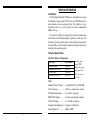
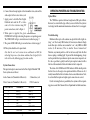
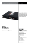
DVI Video with Stereo Audio
(Supporting Single-Link DVI)
Models 7500 & 7501
USER’S MANUAL
WORLD HEADQUARTERS
55 Cabot Court
Hauppauge, N.Y. 11788 USA
Tel: (631) 273-0404 Fax: (631) 273-1638
www.commspecial.com
Email: [email protected]
Communications Specialties Pte Ltd
100 Beach Road
#22-09 Shaw Tower
Singapore 189702
Tel: +65 6391 8790 Fax: +65 6396 0138
Email: [email protected]
P/N: 126184 Rev. C
CONTENTS
General Information .................................................... 3
Introduction ............................................................ 3
Technical Specifications .......................................... 3
Installation Instructions .............................................. 5
Installation Procedure ............................................. 5
System Connections ............................................... 6
Alarm Switch Settings ............................................ 7
Indicator LEDs ....................................................... 8
Lock Bandwidth & Equalizer Settings .................... 9
Operating Pointers and Troubleshooting .................. 11
Maintenance and Repairs ......................................... 12
Limited Warranty ...................................................... 13
© 2007, Communications Specialties, Inc.. Pure Digital Fiberlink is a registered trademark of
Communications Specialties, Inc.
2
15
GENERAL INFORMATION
Introduction
The Pure Digital Fiberlink® 7500 Series is a transmitter/receiver pair
that transmits a single channel of DVI video (up to WUXGA) and two
audio channels over one single mode fiber. It is available as a freestanding box unit or as a card version for use in the rackmountable
6000A card cage.
The system’s all digital encoding delivers noise-free transmissions
that retain all of their initial parameters, regardless of fiber optic cable
attenuation. System operation may be easily monitored using integral
indicator LEDs on each unit that continuously signify the presence of
baseband video and audio signals.
Technical Specifications
Model Part Number Configuration:
Unit Type
Transmitter Box
Transmitter Rack Card
Receiver Box
Receiver Rack Card
Part Number
7500-B7S
7500-C7S
7501-B7S
7501-C7S
All units operate
using CWDM
Multiplexing using
single mode fiber.
ST connectors are
provided.
Video:
Number of Video Channels ...... 1 single-link DVI up to 1920x1200
Video Processing ...................... 24 bits, no compression or scaling
DVI Input Loop-through .......... Yes, on Box version only
EDID (DDC) Support ............... Yes, from loop-through or internal
Pixel Clock Range .................... 25 - 165 Mhz, continuous
Scanning System Supported ..... Progressive or Interlaced
Format Supported ..................... RGB or YPrPb
14
3
Audio:
Number of Audio Channels ..... 2, unbalanced
Frequency Response ................. +0/-0.5 dB, 20 Hz to 20 kHz
Bits-per-Sample/Sampling Rate ... 24 bits; >48kHz
Maximum Audio Level .............. +10 dBu
SNR (A-Weighted) ..................... 100 dB
THD+N ....................................... 0.001%, 20 Hz - 20 kHz
Channel Phase Differential ........ +0.1o
Crosstalk ..................................... 100 dB (1 kHz)
Input Impedance ......................... >24 k Ohms
Output Impedance ...................... < 1 Ohm
Audio to Video Diff. Delay (skew) . 300 uSec
Optical:
Operating Wavelength .............. CWDM (1300 - 1600 nm band )
Optical Fibers ........................... 8-10/125 microns SM
Optical Connector .................... ST
Class I Laser Product complies with FDA performance standard for
laser products, Title 21, Code of Federal Regulations, Sub-Chapter J.
Miscellaneous:
Operating Temp. Range ........... -20oC to +50oC
Operating Power ...................... 9-24 Volts AC or DC@10 watts (max.)
Loss Budget and Maximum Transmission Distance:
Wavelength
Loss Budget (in dB) Distance* (in km)
1310 SM
0-15
15
*Distance specifications are only approximate and are not
guaranteed. Operating loss budget must not be exceeded.
4
LIMITED WARRANTY
Communications Specialties, Inc. (CSI) warrants that for a period of three
years after purchase by the Buyer, the Pure Digital Fiberlink® 7500 Series
transmitter and receiver units will be free from defects in material and workmanship under normal use and service. A Return Material Authorization
(RMA) number must be obtained from CSI before any equipment is
returned by the Buyer. CSI’s obligation under this warranty will be limited,
at its option, to either the repair or replacement of defective units, including
free materials and labor. In no event shall CSI be responsible for any incidental or consequential damages or loss of profits or goodwill. CSI shall
not be obligated to replace or repair equipment that has been damaged by
fire, war, acts of God, or similar causes, or equipment that has been serviced
by unauthorized personnel, altered, improperly installed or abused.
RMA numbers and repairs can be obtained from:
In the Asia Pacific Region:
Communications Specialties, Inc.
55 Cabot Court
Hauppauge, NY 11788 USA
Tel: (631) 273-0404 Fax: (631) 273-1638
www.commspecial.com
Email: [email protected]
Communications Specialties Pte Ltd
100 Beach Road, #22-09 Shaw Tower
Singapore 189702
Tel: +65 6391 8790 Fax: +65 6396 0138
Email: [email protected]
Please have your serial number (located on the top label of the unit)
available when contacting us.
13
MAINTENANCE AND REPAIRS
The Pure Digital Fiberlink® 7500 Series transmission system has been
manufactured using the latest semiconductor devices and techniques
that electronic technology has to offer. It has been designed for long,
reliable and trouble-free service and are not normally field repairable.
Should difficulty be encountered, Communications Specialties maintains a complete service facility to render accurate, timely and reliable
service of all products.
The only maintenance that can be provided by the user is to ascertain
that the optical connectors are free of dust or dirt that could interfere
with light transmission and that electrical connections are secure and
accurate. DANGER! Always turn off the transmitter’s power before removing the optical fiber from either the transmitter or the receiver unit.
All other questions or comments should be directed to our Customer
Service Department. It should be noted that many “problems” can easily be solved by a simple phone call.
DANGER! The transmitting element in the Pure Digital Fiberlink 7500 transmitter
unit contains a solid state Laser Diode located within the optical connector. This
device emits invisible infrared electromagnetic radiation which can be harmful to
human eyes. The radiation from this optical connector, if viewed at close range
without a fiber optic cable connected to the optical connector, may be of
sufficient intensity to cause instantaneous damage to the retina of the eye. Direct
viewing of this radiation should be avoided at all times.
INSTALLATION INSTRUCTIONS
Installation Procedure:
The Pure Digital Fiberlink® 7500 Series transmission system is ready
for immediate use. There are indicator LEDs on the units for monitoring purposes. The following instructions describe the typical installation procedure and the function of the LED indicators.
1. Power off the PC and 7500 Units.
2. Connect the DVI video source (PC) to the video input DVI-D
connector on the transmitter unit.
3. Box Units: Connect a monitor to the loop-thru input of transmitter
unit if that is the monitor type to be used on the receiver end of the
link. Ensure that the Loop/Internal EDID Switch is in the “Loop”
position.
If the loop-thru default settings are desired, ensure that the Loop/
Internal EDID Switch is in the “Internal” position. No monitor
connection to the transmitter box is required for this loop-thru position.
Note: On card units, the internal loop-thru function is done
automatically.
4. Connect the video output(s) on the receiver unit to the DVI-D
connector(s).
5. Connect the fiber optic cable between the two Pure Digital Fiberlink
units.
12
5
6. Connect the audio input signals to the transmitter stereo jack and the
audio output to the receiver stereo jack.
7. Apply power to both the Pure Digital
Fiberlink units and the PC or video
source. For box versions using DC
power connections, refer to Figure 1.
8. When power is applied, the green
POWER LED will light, indicating the presence of operating power.
The VIDEO LED will give an indication as described on page 7.
9. The green AUDIO LED will give an indication as stated on page 7.
10.The system should now be operational.
Note that the rack card version has an additional red LED for
indicating the presence of an alarm condition (loss of signal). Refer
to the table on the following page for alarm enables.
System Connections:
The input and output connections for the Pure Digital Fiberlink 7500
Series system are as follows:
Audio Connector (Transmitter & Receiver):
3.5mm stereo jack
Video Connector (Transmitter & Receiver):
DVI-D connector
Video Pin Out:
1
2
3
`
4
5
6
7
Transmitter
Red (-)
Red (+)
Red Shield
N/C
N/C
DDC CLK
DDC Data
6
OPERATING POINTERS AND TROUBLESHOOTING
Optical Fiber:
The 7500 Series operates with most single mode (SM) optical fibers.
However, be aware that the type of fiber you use will affect the system’s
loss budget and the maximum transmission distance that it can support.
Troubleshooting:
Multimode fiber optic cable contains an optical fiber with a light carrying “core” that is only .0025 inches (62.5 microns) in diameter. Single
mode fiber optic cable has an even smaller “core,” only .00032 to .0004
inches (8-10 microns). This is smaller than a human hair!
Therefore, any minute particles of dirt or dust can easily block the fiber
from accepting or radiating light. To prevent this from happening, always
use the provided dust caps whenever optical connectors are exposed to air.
It is also a good idea to gently clean the tip of an optical connector with a
lint-free cloth moistened with alcohol whenever dust is suspected.
The status of the VIDEO and AUDIO indicator LEDs should provide
the first clue as to the origin of an operational failure. If these are off, it
usually means that the fiber is broken or has too much attenuation. Next,
be certain that the input and output signal connections are correct.
If, after reviewing the above possibilities, the system is still not operating, please contact the Customer Service Department for further assistance.
Receiver
Red (-)
Red (+)
Red Shield
N/C
N/C
DDC CLK
DDC Data
11
Lock Bandwidth (BW)
Switches 1 and 2 control the lock bandwidth:
Wide
ide
Medium
dium
Narrow
row
Very Narrow
BW EQ
BW EQ
BW EQ
BW EQ
1 2 3 4
1 2 3 4
1 2 3 4
1 2 3 4
Input Equalization (EQ)
Switches 3 and 4 control the input equalization:
Short
Medium
Long
Very Long
1 2 3 4
1 2 3 4
1 2 3 4
1 2 3 4
BW EQ
BW EQ
BW EQ
BW EQ
Video Pin Out:
8
9
10
11
12
13
14
15
16
17
18
19
20
21
22
23
24
Transmitter
N/C
Green (-)
Green (+)
Green Shield
N/C
N/C
+5V Power
GND (for +5V)
Hot Plug Detect
Blue (-)
Blue (+)
Blue Shield
N/C
N/C
Pixel Click Shield
Pixel Click (+)
Pixel Click (-)
Receiver
N/C
Green(-)
Greeen(+)
Green Shield
N/C
N/C
+5V Power
GND (for +5V)
Hot Plug Detect
Blue (-)
Blue (+)
Blue Shield
N/C
N/C
Pixel Click Shield
Pixel Click (+)
Pixel Click (-)
TX Box EDID Switch Settings:
Switch Position
Loop
Internal
EDID Information Source
From loop-thru monitor
Default Settings, Generated Internally
Alarm Switch Settings (Transmitter; Card Version Only):
Switch Position
1
2
10
Alarm Indication
Loss of Video
N/A
7
On
Off
Enabled Disabled
N/A
N/A
Alarm Switch Settings (Receiver; Card Version Only):
Switch Position
1
2
Alarm Indication
Loss of Signal
Loss of Video
On
Off
Enabled Disabled
Enabled Disabled
Note: “Loss of Video” refers to loss of valid DVI video stream.
“Loss of Signal” refers to the absence of an optical signal.
Indicator LEDs and Alarm Circuitry:
The stand-alone box versions of the Pure Digital Fiberlink 7500 and
7501 units have three integral indicator LEDs that are used to monitor
the state of the units.
The rack card versions of these products have an additional red indicator LED that lights when an alarm condition exists. The rack card unit
also provides an output to drive a model 6020 Alarm Sensing Module
which provides an audible tone and activates a set of contacts for external signaling purposes.
The status of the LEDs are as follows:
TRANSMITTER and RECEIVER:
Power: ON (GREEN): Indicates that correct power has been
applied.
Audio:
Video:
OFF: Indicates no video detected over the fiber and, as a
result, no video present on the output.
STEADY GREEN: Indicates DVI Video detected
over fiber and, as a result, video present on the output.
Audio:
OFF: Indicates no audio detected over fiber and, as a result,
no active audio detected by the receiver unit.
BLINKING GREEN: Audio detected over fiber and, as a
result, active audio detected by the receiver unit.
Alarm: ON (RED): Loss of video or optical signal (rack card only).
Lock Bandwidth & Input Equalization:
The 7500 transmitter units have a Lock Bandwidth (BW) and Input
Equalizer (EQ) Setting Dip switches located on the front panel. The
default factory settings is all switches in the up position. The default
equalizer (EQ) setting is for a short DVI cable, less than 10 feet.
The default Bandwidth (BW) setting is WIDE BW. This should
work for most clean, “noise-free” DVI sources. A narrow bandwidth
setting should be used for dirty or noisy DVI sources.
1 2 3 4
Factory Defaults:
TRANSMITTER:
Video:
RECEIVER:
OFF: Indicates no video detected on the input.
STEADY GREEN: Indicates DVI Video detected on
the input.
All Switches in the up position:
BW EQ
OFF: Indicates no audio detected on the transmitter unit.
BLINKING GREEN: Audio detected on the transmitter unit.
Alarm: ON (RED): Loss of video (rack card only)
8
9
Lock Bandwidth (BW)
Switches 1 and 2 control the lock bandwidth:
Wide
ide
Medium
dium
Narrow
row
Very Narrow
BW EQ
BW EQ
BW EQ
BW EQ
1 2 3 4
1 2 3 4
1 2 3 4
1 2 3 4
Input Equalization (EQ)
Switches 3 and 4 control the input equalization:
Short
Medium
Long
Very Long
1 2 3 4
1 2 3 4
1 2 3 4
1 2 3 4
BW EQ
BW EQ
BW EQ
BW EQ
Video Pin Out:
8
9
10
11
12
13
14
15
16
17
18
19
20
21
22
23
24
Transmitter
N/C
Green (-)
Green (+)
Green Shield
N/C
N/C
+5V Power
GND (for +5V)
Hot Plug Detect
Blue (-)
Blue (+)
Blue Shield
N/C
N/C
Pixel Click Shield
Pixel Click (+)
Pixel Click (-)
Receiver
N/C
Green(-)
Greeen(+)
Green Shield
N/C
N/C
+5V Power
GND (for +5V)
Hot Plug Detect
Blue (-)
Blue (+)
Blue Shield
N/C
N/C
Pixel Click Shield
Pixel Click (+)
Pixel Click (-)
TX Box EDID Switch Settings:
Switch Position
Loop
Internal
EDID Information Source
From loop-thru monitor
Default Settings, Generated Internally
Alarm Switch Settings (Transmitter; Card Version Only):
Switch Position
1
2
10
Alarm Indication
Loss of Video
N/A
7
On
Off
Enabled Disabled
N/A
N/A
6. Connect the audio input signals to the transmitter stereo jack and the
audio output to the receiver stereo jack.
7. Apply power to both the Pure Digital
Fiberlink units and the PC or video
source. For box versions using DC
power connections, refer to Figure 1.
8. When power is applied, the green
POWER LED will light, indicating the presence of operating power.
The VIDEO LED will give an indication as described on page 7.
9. The green AUDIO LED will give an indication as stated on page 7.
10.The system should now be operational.
Note that the rack card version has an additional red LED for
indicating the presence of an alarm condition (loss of signal). Refer
to the table on the following page for alarm enables.
System Connections:
The input and output connections for the Pure Digital Fiberlink 7500
Series system are as follows:
Audio Connector (Transmitter & Receiver):
3.5mm stereo jack
Video Connector (Transmitter & Receiver):
DVI-D connector
Video Pin Out:
1
2
3
`
4
5
6
7
Transmitter
Red (-)
Red (+)
Red Shield
N/C
N/C
DDC CLK
DDC Data
6
OPERATING POINTERS AND TROUBLESHOOTING
Optical Fiber:
The 7500 Series operates with most single mode (SM) optical fibers.
However, be aware that the type of fiber you use will affect the system’s
loss budget and the maximum transmission distance that it can support.
Troubleshooting:
Multimode fiber optic cable contains an optical fiber with a light carrying “core” that is only .0025 inches (62.5 microns) in diameter. Single
mode fiber optic cable has an even smaller “core,” only .00032 to .0004
inches (8-10 microns). This is smaller than a human hair!
Therefore, any minute particles of dirt or dust can easily block the fiber
from accepting or radiating light. To prevent this from happening, always
use the provided dust caps whenever optical connectors are exposed to air.
It is also a good idea to gently clean the tip of an optical connector with a
lint-free cloth moistened with alcohol whenever dust is suspected.
The status of the VIDEO and AUDIO indicator LEDs should provide
the first clue as to the origin of an operational failure. If these are off, it
usually means that the fiber is broken or has too much attenuation. Next,
be certain that the input and output signal connections are correct.
If, after reviewing the above possibilities, the system is still not operating, please contact the Customer Service Department for further assistance.
Receiver
Red (-)
Red (+)
Red Shield
N/C
N/C
DDC CLK
DDC Data
11
MAINTENANCE AND REPAIRS
The Pure Digital Fiberlink® 7500 Series transmission system has been
manufactured using the latest semiconductor devices and techniques
that electronic technology has to offer. It has been designed for long,
reliable and trouble-free service and are not normally field repairable.
Should difficulty be encountered, Communications Specialties maintains a complete service facility to render accurate, timely and reliable
service of all products.
The only maintenance that can be provided by the user is to ascertain
that the optical connectors are free of dust or dirt that could interfere
with light transmission and that electrical connections are secure and
accurate. DANGER! Always turn off the transmitter’s power before removing the optical fiber from either the transmitter or the receiver unit.
All other questions or comments should be directed to our Customer
Service Department. It should be noted that many “problems” can easily be solved by a simple phone call.
DANGER! The transmitting element in the Pure Digital Fiberlink 7500 transmitter
unit contains a solid state Laser Diode located within the optical connector. This
device emits invisible infrared electromagnetic radiation which can be harmful to
human eyes. The radiation from this optical connector, if viewed at close range
without a fiber optic cable connected to the optical connector, may be of
sufficient intensity to cause instantaneous damage to the retina of the eye. Direct
viewing of this radiation should be avoided at all times.
INSTALLATION INSTRUCTIONS
Installation Procedure:
The Pure Digital Fiberlink® 7500 Series transmission system is ready
for immediate use. There are indicator LEDs on the units for monitoring purposes. The following instructions describe the typical installation procedure and the function of the LED indicators.
1. Power off the PC and 7500 Units.
2. Connect the DVI video source (PC) to the video input DVI-D
connector on the transmitter unit.
3. Box Units: Connect a monitor to the loop-thru input of transmitter
unit if that is the monitor type to be used on the receiver end of the
link. Ensure that the Loop/Internal EDID Switch is in the “Loop”
position.
If the loop-thru default settings are desired, ensure that the Loop/
Internal EDID Switch is in the “Internal” position. No monitor
connection to the transmitter box is required for this loop-thru position.
Note: On card units, the internal loop-thru function is done
automatically.
4. Connect the video output(s) on the receiver unit to the DVI-D
connector(s).
5. Connect the fiber optic cable between the two Pure Digital Fiberlink
units.
12
5
Audio:
Number of Audio Channels ..... 2, unbalanced
Frequency Response ................. +0/-0.5 dB, 20 Hz to 20 kHz
Bits-per-Sample/Sampling Rate ... 24 bits; >48kHz
Maximum Audio Level .............. +10 dBu
SNR (A-Weighted) ..................... 100 dB
THD+N ....................................... 0.001%, 20 Hz - 20 kHz
Channel Phase Differential ........ +0.1o
Crosstalk ..................................... 100 dB (1 kHz)
Input Impedance ......................... >24 k Ohms
Output Impedance ...................... < 1 Ohm
Audio to Video Diff. Delay (skew) . 300 uSec
Optical:
Operating Wavelength .............. CWDM (1300 - 1600 nm band )
Optical Fibers ........................... 8-10/125 microns SM
Optical Connector .................... ST
Class I Laser Product complies with FDA performance standard for
laser products, Title 21, Code of Federal Regulations, Sub-Chapter J.
Miscellaneous:
Operating Temp. Range ........... -20oC to +50oC
Operating Power ...................... 9-24 Volts AC or DC@10 watts (max.)
Loss Budget and Maximum Transmission Distance:
Wavelength
Loss Budget (in dB) Distance* (in km)
1310 SM
0-15
15
*Distance specifications are only approximate and are not
guaranteed. Operating loss budget must not be exceeded.
4
LIMITED WARRANTY
Communications Specialties, Inc. (CSI) warrants that for a period of three
years after purchase by the Buyer, the Pure Digital Fiberlink® 7500 Series
transmitter and receiver units will be free from defects in material and workmanship under normal use and service. A Return Material Authorization
(RMA) number must be obtained from CSI before any equipment is
returned by the Buyer. CSI’s obligation under this warranty will be limited,
at its option, to either the repair or replacement of defective units, including
free materials and labor. In no event shall CSI be responsible for any incidental or consequential damages or loss of profits or goodwill. CSI shall
not be obligated to replace or repair equipment that has been damaged by
fire, war, acts of God, or similar causes, or equipment that has been serviced
by unauthorized personnel, altered, improperly installed or abused.
RMA numbers and repairs can be obtained from:
In the Asia Pacific Region:
Communications Specialties, Inc.
55 Cabot Court
Hauppauge, NY 11788 USA
Tel: (631) 273-0404 Fax: (631) 273-1638
www.commspecial.com
Email: [email protected]
Communications Specialties Pte Ltd
100 Beach Road, #22-09 Shaw Tower
Singapore 189702
Tel: +65 6391 8790 Fax: +65 6396 0138
Email: [email protected]
Please have your serial number (located on the top label of the unit)
available when contacting us.
13