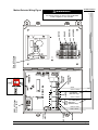
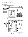
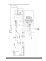
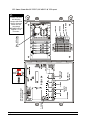
1
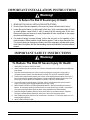
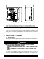
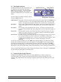
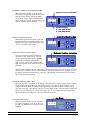
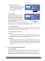
RollSeal SC-325 & SC-650 Controllers Owners Manual RollSeal 1733 County Road 68 Bremen, Alabama 35033 256-287-7000 Manual No. 4801-5156 Rev 10-2014 Owners Manual RollSeal SC-325 & SC-650Controllers Table of Contents 1 Warnings (Avertissements) .................................................................................................................................... 4 2 Limited Warranty ................................................................................................................................................. 10 3 Ratings and Specifications ................................................................................................................................... 11 4 Introduction .......................................................................................................................................................... 11 4.1 5 6 How the Smart Controllers Communicate with the RollSeal Automatic Doors. ...................................... 12 Smart Controller User Interface ........................................................................................................................... 12 5.1 The Power Switch ..................................................................................................................................... 12 5.2 The Display Indicator ............................................................................................................................... 13 5.3 Interpreting the Display Indicator ............................................................................................................. 13 5.4 Safety Beam .............................................................................................................................................. 15 5.5 Leading Edge Switch ................................................................................................................................ 15 5.6 Home and Safety Limit Switches ............................................................................................................. 15 SC-325 and SC-650 Initial Setup ......................................................................................................................... 15 6.1 Program Mode .......................................................................................................................................... 15 6.2 Acceleration and Deceleration Range ....................................................................................................... 18 6.3 Switch Settings ......................................................................................................................................... 19 6.4 Door Setup ................................................................................................................................................ 19 7 Jog Mode .............................................................................................................................................................. 20 8 Door Activation Methods ..................................................................................................................................... 20 9 8.1 Directional Switch Input ........................................................................................................................... 21 8.2 Manual (Single) Switch Input ................................................................................................................... 21 8.3 Timed Switch Input .................................................................................................................................. 21 Troubleshooting Controller and/or Door .............................................................................................................. 22 9.1 P12 – Input Status Indicators .................................................................................................................... 22 9.2 Error Codes and Recommended Action.................................................................................................... 23 10 Controller Installation and Setup .......................................................................................................................... 24 10.1 Tools Required.......................................................................................................................................... 24 10.2 Installation Instructions............................................................................................................................. 24 10.3 Typical Smart Controller Installation ....................................................................................................... 25 10.4 Connection of Controller to Head Unit. .................................................................................................... 26 10.5 Installing Prewired Switches .................................................................................................................... 26 10.6 Power Connection with Disconnect .......................................................................................................... 27 10.7 Preparation for Operation ......................................................................................................................... 27 Page 2 RollSeal SC-325 & SC-650 Controllers Part No 4801-5156 Rev 10-2014 11 Accessories .......................................................................................................................................................... 28 11.1 Remote Transmitter and Receiver (Ordered Separately) .......................................................................... 28 11.2 2-Button Close/Open Switch Module (Ordered Separately) .................................................................... 29 11.3 Ceiling/Wall Mount Pull Switch Assembly (Ordered Separately) ........................................................... 29 11.4 Wiring Motion Detector (Falcon & Falcon XL)....................................................................................... 30 12 Wiring Diagrams, Schematics, etc. ...................................................................................................................... 32 12.1 Smart Controller SC-325 V1 Layout ........................................................................................................ 32 12.2 Smart Controller SC-325 V1 Connection Diagram (Internal Wiring)..................................................... 33 12.3 Smart Controller SC-325 V2, SC-650 V1 & V2 Layout .......................................................................... 34 12.4 Smart Controller SC-325 V2, SC-650 V1 & V2 Connection Diagram (Internal Wiring) ....................... 35 12.5 Connecting AC Power to the Smart Controller ........................................................................................ 36 12.6 RS-500/600 Motor Brake Rectifier Wiring Diagram ............................................................................... 37 12.7 Connecting Power to the SC-325 Controller ............................................................................................ 38 12.8 Connecting to the Automatic Doors ......................................................................................................... 39 12.9 Interlocking Two Automatic Doors.......................................................................................................... 40 12.10 Connecting the Operator Switches to the Smart Controller ..................................................................... 41 12.11 Connecting Switches and Remote Receiver to the Smart Controller ....................................................... 42 12.12 Connecting Switches to the SC-325 Wiring Option “-W01”Controller P/N 6607-8057 and 6607-8058 43 12.13 Connecting Moving Door Warning Light to the Smart Controller .......................................................... 44 12.14 RollSeal Automatic Door Wiring Diagram .............................................................................................. 45 12.15 RollSeal Smart Controller Wiring Diagram ............................................................................................. 46 13 Replacement and Optional Parts .......................................................................................................................... 47 Part No 4801-5156 Rev 10-2014 RollSeal SC-325 & SC-650 Controllers Page 3 1 Warnings (Avertissements) ! Warning! Disconnect All Power Sources Before Installing This Equipment. Failure To Disconnect Power Source Can Result In Property Damage, Serious Injury Or Death! !! Warning! Dangerous Rotating Machinery! Keep Hands, Clothing, Etc. Clear When Operating! Do Not Operate Without All Guards And Covers In Place! ! Warning! All Wiring Should Be In Accordance with National Electrical Codes Or Other Local Codes. !! Warning! The Installer Is Responsible For Complying With All Relevant Regulations, Such As National Wiring Regulations And Accident Prevention Regulations. Particular Attention Must Be Given To The Cross-sectional Areas Of Conductors, The Selection Of Fuses Or Other Protection, And Protective Earth/Ground Connections! !! Warning! Drives Are Intended As Components For Incorporation Into Electrical Control Systems Or Machines. It Is The Responsibility Of The Installer To Ensure That The Drive Is Installed Safely And In Accordance With Any Regulations Which Apply To The End Product At The Place Of Use, For Example, Regarding Safety Or Electromagnetic Compatibility. To Ensure Mechanical Safety, Additional Safety Devices Such As Electro-Mechanical Interlocks May Be Required! Page 4 RollSeal SC-325 & SC-650 Controllers Part No 4801-5156 Rev 10-2014 !! Warning! The Voltages In The Power Cables And Certain Parts Of The Drive Can Result In Death. Whenever The Drive Has Been Used, It Must Be Isolated And Disconnected For 5 Minutes Before Any Work Commences. ! Danger! Only Qualified Electrical Personnel Familiar With The Construction And Operation Of This Equipment And The Hazards Involved Should Install, Adjust, And/Or Service This Equipment. Read And Understand This Manual In Its Entirety Before Proceeding. Failure To Observe This Precaution Could Result In Severe Bodily Injury Or Death! ! Warning! Item 4501-6312 (Warning Moving Door Label) Supplied With Door, MUST Be Installed On Inside Of Cooler/Freezer Beside Door Opening. Part No 4801-5156 Rev 10-2014 RollSeal SC-325 & SC-650 Controllers Page 5 IMPORTANT INSTALLATION INSTRUCTIONS ! Warning! To Reduce The Risk Of Severe Injury Or Death: 1. READ AND FOLLOW ALL INSTALLATION INSTRUCTIONS. 2. Do not connect the door operator to the source of power until instructed to do so. 3. Locate the control station: (a) within sight of the door, (b) at a minimum height of 5 feet so small children cannot reach it, and (c) away from all moving parts of the door. Remove all ropes and remove or make inoperative all locks connected to the garage door before installing opener. 4. For products having a manual release, instruct the end user on the operation of the manual release. Where possible, install the door opener 7 feet or more above the floor. For products having an emergency release, mount the emergency release within reach, but at least 6 feet above the floor and avoiding contact with vehicles to avoid accidental release. IMPORTANT SAFETY INSTRUCTIONS !! Warning! To Reduce The Risk Of Severe Injury Or Death: 1. 2. READ AND FOLLOW ALL INSTRUCTIONS! Never let children operate or play with door controls. Keep the remote control (where provided) away from children. 3. Personnel should keep away from a door in motion and keep the moving door in sight until it is completely closed or opened. NO ONE SHOULD CROSS THE PATH OF A MOVING DOOR. 4. Test the door’s safety features at least once a month. After adjusting either the speed or the limit of travel, retest the door operator’s safety features. Failure to adjust the operator properly may cause severe injury or death. NEVER GO UNDER A STOPPED, PARTIALLY OPEN DOOR. 5. For products having a manual release, if possible, use the manual release only when the door is closed. Use caution when using this release when the door is open. 6. KEEP DOORS PROPERLY OPERATING AND BALANCED. See Door Manufacturer’s Owner’s Manual. An improperly operating or balanced door can cause severe injury or death. Have trained door systems technician make repairs to cables, spring assemblies, and other hardware. 7. Install the Entrapment Warning label next to the control button in a prominent location. Install the Emergency Release Marking. Attach the marking on or next to the emergency release. 8. After installing the opener, the door must reverse when it contacts a 1-1/2 inch high object (or a 2 x 4 board laid flat) on the floor. 9. SAVE THESE INSTRUCTIONS. Page 6 RollSeal SC-325 & SC-650 Controllers Part No 4801-5156 Rev 10-2014 French Translated Warnings ! Avertissement! Disjoindre fournissent de l'énergie tout les sources avant qu'installer cet équipement. F|ailure| à disjoindre la source de pouvoir peut résulter dans dommage de propriété, blessure sérieuse ou mort ! ! Avertissement! Mécanisme tournant dangereux ! Garder les mains, vêtissant, etcC|lear| quand fonctionner ! Ne fonctionnez pas sans toutes gardes et couvertures dans lieu ! ! Avertissement! Tout montage sur fil de fer doit être selon codes électriques nationaux ou autres indicatifs régionaux. ! Avertissement! L'Installer est responsable pour conformer avec tout règlement pertinent, telles que règlement et règlement de prévention d'accident de montage sur fil de fer nationaux. Pl'attention articulaire doit être donnée pour les aires sectionnelles transversales de conducteurs, le choix d'elles fusées ou autre protection, et terre / prises de terre protecteur ! ! Avertissement! Les promenades en voiture sont projetées comme composants pour l'incorporation dans les systèmes ou machines d'autorité électriques. Il est la responsabilité de l'installer pour assurer que la promenade en voiture est installé sans risque et selon tout règlement qui appliquer pour le produit fini au lieu d'utilisation, par exemple concernant sécurité ou la compatibilité électromagnétique. Pour assurer que sécurité mécanique, les dispositif de sécurité supplémentaires telle que de |electro| mécanique enclenche pouvoir être exigé! Part No 4801-5156 Rev 10-2014 RollSeal SC-325 & SC-650 Controllers Page 7 ! Avertissement! Les tensions dans le pouvoir câblent et certains parties de la promenade en voiture peuvent résulter dans la mort. Wle |henever| la promenade en voiture a été utilisé il doit être isolé et détaché pendant 5 procès avant que tout travail commence. ! Danger ! Seulement familier électrique de personnel qualifié avec la construction et opération de cet équipement et les hasards ont enveloppé devoir installer, arranger, et/ou - la révision cet équipement. R|ead| et comprendre ce manuel en entier avant que procéder. F|ailure| à observer cette précaution peut résulter dans dommage corporel sévère ou mort ! ! Avertissement! Point 4501-6312 (Avertissement Moving étiquette de porte) Livré avec porte, doit être installé à l'intérieur du réfrigérateur / congélateur côté Ouverture de la porte. Page 8 RollSeal SC-325 & SC-650 Controllers Part No 4801-5156 Rev 10-2014 LES INSTRUCTIONS D'INSTALLATION IMPORTANTES ! AVERTISSEMENT! À réduire le risque de blessure sévère ou mort: 1. LU ET SUIVENT TOUTES INSTRUCTIONS D'INSTALLATION. 2. Ne liez pas l'opérateur de porte per la source de pouvoir jusqu'à instruit faire ainsi. 3. Localisez la station de commande: (a) en vue de la porte, (b) à un minimum la hauteur de 5 pieds ainsi petit enfants ne peuvent pas l'atteindre, et (c) loin de tous parties en mouvement de la porte. 4. Pour produits ayant un délivrance manuelle, instruire l'utilisateur final sur l'opération de la délivrance manuelle. RÈGLEMENTS DE SÉCURITÉ IMPORTANTS ! AVERTISSEMENT! À réduire le risque de blessure sévère ou mort: 1. LU ET SUIVENT TOUTES INSTRUCTIONS! 2. Jamais laisser fonctionner enfants ou mouvoir vivement avec les autorités de porte. Gardez la télécommande (où a fourni) loin des enfants. 3. Le personnel devrait garder loin une porte dans mouvement et subsistance la porte en mouvement dans vue jusqu'à est complètement fermé ou avoir ouvert. CES AUCUNS DOIVENT CROISER LE CHEMIN D'UNE PORTE EN MOUVEMENT. 4. Éprouvez les traits de sécurité de la porte au moins une fois par mois. Après qu'arrangeant la vitesse ou la fin de course, retest les traits de sécurité de l'opérateur de porte. Manque à arranger l'opérateur correctement peut causer blessure sévère ou mort. 5. Pour produits ai manuel la délivrance, si possible, utiliser la délivrance manuelle seulement quand la porte est fermée. Précaution d'utilisation à utiliser cette délivrance quand la porte est ouverte. 6. GARDER LES PORTES CORRECTEMENT QUI OPÈRE ET ÉQUILIBRÉ. Voir la porte fabricant propriétaire manuel. Un improprement qui opère ou balancé porte peut causer blessure sévère ou mort. Formez les technicien de systèmes de porte faitez les réparations per les câbles, réunions de source, et autre quincaillerie. 7. SAUVEZ CES INSTRUCTIONS. Part No 4801-5156 Rev 10-2014 RollSeal SC-325 & SC-650 Controllers Page 9 2 Limited Warranty All products are warranted to be free from defects in material and workmanship for a period of one (1) year or 100,000 cycles, whichever occurs first, from the date of purchase if installed and used in strict accordance with the installation instructions. Liability is limited to the sale price of any products proved to be defective or, at manufacturers’ option, to the replacement of such products upon their return. No products are to be returned to the manufacturer, until there is an inspection and/or a return-goods authorization (RGA) number is issued. All complaints should be directed first to the authorized distributor who sold the product. If satisfaction is not obtained or the name of the distributor is not known, write the manufacturer that appears below, directed to the attention of Customer Service Manager. This limited warranty is expressly in lieu of any and all representations and warranties expressed or implied, including any implied warranty of merchantability or fitness for a particular purpose. The remedy set forth in this limited warranty shall be the exclusive remedy available to any person. No person has authority to bind the manufacturer to any representation or warranty other than this limited warranty. The manufacturer shall not be liable for any consequential damages resulting from the use of our products or caused by any defect, failure or malfunction of our products. (Some areas do not allow the exclusion or limitation of incidental or consequential damages, so the above limitation or exclusion may not apply to you.) This warranty gives you specific legal rights and you may also have other rights that vary from area to area. Warrantor: RollSeal 1733 County Road 68 Bremen, Al 35055 256-287-7000 Warning!! Page 10 RollSeal SC-325 & SC-650 Controllers Part No 4801-5156 Rev 10-2014 3 Ratings and Specifications Part Number Model Number Power Supply Temperature Range Inputs Outputs Drive Setting Factory Preset Voltage Switch & Jumper Power Cord Switch & Warning Wires with Conduit 4 6607-8055 SC-325-V01-0 6607-8056 6607-8058 6607-8100 SC-325-V02-0 SC-325-V01-000-W01 SC-650-V01-0 115 VAC (SC-325 only) or 230 VAC 50/60 Hz Single Phase 32°F - 115°F (0°C – 46°C) 10 Amps @ 115 VAC Single Phase or 6 Amps @ 240 VAC Single Phase 240 VAC Three Phase ¼ H.P. Version 01 Version 02 Version 01 115 VAC 115 VAC 115 VAC N/A N/A N/A N/A 6607-8101 SC-650-V02-0 8 Amps @ 240 VAC Single Phase 240 VAC Three Phase ½ H.P. Version 01 Version 02 230 VAC 230 VAC N/A -W01 Switch Wiring Option N/A N/A N/A N/A Introduction The RollSeal SC-325 & SC-650 Smart Controllers are intelligent controllers manufactured specifically for the RollSeal RS-500 and RS-600 Automatic Doors. The Smart Controllers will provide safe opening and closing of the door by using a number of internal safety devices plus those features provided in the components of the automatic doors. The Smart Controllers can control the opening and closing speeds of the door, count the number of door operations, and provide status information for remote monitoring of the door position. In addition, the Smart Controllers can combine a number of auxiliary devices to improve the operability of the automatic doors such as: (1) Remote radio controlled inputs for operating the door. (2) Infrared sensors to detect the presence of personnel or machinery requiring passage through the door. (3) Auxiliary lights or alarms that operate in conjunction with door opening or closing. The Smart Controllers are very versatile and simple to operate. The controls are easily operated from the front panel. SC-650 Controller SC-325 Controller Display Indicator Power Switch Main Fuse Part No 4801-5156 Rev 10-2014 RollSeal SC-325 & SC-650 Controllers Page 11 9.75” 6.50” 10.50” 11.50” 4.1 How the Smart Controllers Communicate with the RollSeal Automatic Doors. Inside the upper right housing of the RollSeal Automatic Door is an encoder that sends electrical pulses to the Smart Controller when the door is moving and the controller is in the normal operating mode. (See Section 12.14 for wiring diagram of the encoder). The controllers refer to the position of the door in units of “Counts”, which is based upon the number of encoded pulses that the encoder sends to the controller. NOTE: The term Position Units is used throughout this document and refers to the position of the door in units of Counts. A Count of zero is assigned to the full open position where the Home switch operates, and the highest count is assigned to the full closed position. The maximum number of counts that the controller will read will depend upon the particular installation. In general, a count is approximately equal to 1/8 inch of door movement. Several of the parameters of the controller are displayed in units of Counts, such as the Actual Position, the Open and Closed Limit Positions and the Acceleration and Deceleration Ranges. 5 Smart Controller User Interface 5.1 The Power Switch The Power Switch of the Smart Controller is located on the left side of the controller box as illustrated on the previous page. The switch controls power to the Smart Controllers and to the automatic doors. The Main Fuse is located on the outside, bottom-left of the enclosure. ! Warning! DO NOT Turn The Power ON Until All Of The Following Items Are Completed: All Wire And Cable Connections Are Completed. The Voltage Selection Switch And Jumper Are Set To Match The Required Supply Voltage. The Motor Brake Rectifier Is Wired Accordingly To Match The Required Supply Voltage. Refer to Section 6.3 for Switch Settings information. Refer to Section 12.1 (for V1) or 12.3 (for V2) and 12.5 for the location of SWX2 on PCB 154 and J1 on the Motor Drive board assembly. Refer to Section 12.6 for specific RS-500/600 Motor Brake Rectifier wiring diagrams. Page 12 RollSeal SC-325 & SC-650 Controllers Part No 4801-5156 Rev 10-2014 5.2 The Display Indicator The Display Indicator can show four different types of readings that can be selected by pressing the Mode button on the Display. Each time the Mode button is depressed the display steps to the next parameter as indicated by the green LED next to the display. Up/Down Arrows The four readings on the Display Indicator selected by using the Mode button are: Mode Button Safety Beam Obstructed Actual Position – The position of the door curtain in relative position units called Counts. See Section 4.1 for a description of Counts. A low Count reading indicates that the door is at the top or open position. The highest Count reading is when the door is at the bottom or closed position. Open Speed – The percentage of full speed that the door will open. The full speed will depend on the type of drive motor installed. This can be changed from a low of 20 percent to a high of 100 percent. Close Speed – The percentage of full speed that the door will close. The full speed will depend on the type of drive motor installed. This can be changed from a low of 20 percent to a high of 75 percent. Total Cycles – The total number of times (cycles) that the door has been opened and closed. The value displayed is in units of 100 cycles. For example a reading of 20 means that the door has been operated between 2000 and 2099 times. Service Cycles – The number of times (cycles) that the door has been opened and closed since the last service reset. The value displayed is in units of 100 cycles. For example, a reading of 20 represents between 2000-2999 cycles. This cycle count is used for service purposes. Refer to Section 6.1 for information on how to reset this count and how to set Service Reminders. To view each of the four parameters, press the Mode button repeatedly until the green LED on the Display Indicator shows the desired parameter to be read or changed. Use the Up/Down arrows to adjust the Speed percentage to the desired setting. To read the number of times the door has been cycled, press the Mode button until the green LED beside Cycles (x100) is lighted. To return to the Actual Position, press the Mode button again, or wait a few seconds and the controller will automatically return to displaying Actual Position. There is an LED on the Display Indicator that will light when the Safety beam is interrupted. See Section 5.4 for more discussion on the function of the Safety Beam. 5.3 Interpreting the Display Indicator In addition to the readings that can be selected by using the Mode button, the Smart Controller will occasionally display other readings on the Display Indicator that can show the operating status of the controller. This section describes some other types of displays that will occur in the normal operation of the controllers. Part No 4801-5156 Rev 10-2014 RollSeal SC-325 & SC-650 Controllers Page 13 SOFTWARE VERSION AND MODEL NUMBER When the Smart Controller is turned off and subsequently on again, the Display Indicator will flash the current software version and model number in the display. This will remain on the display about two seconds. Then the display will show the Actual Position of the door. Software Version Number S 8## Model Number 8 = SC-325 Model 9 = SC-650 Model ACTUAL POSITION READING When displaying the actual position of the door, the Display Indicator will appear similar to the diagram on the right. In the example shown, the door is in a position of 240 counts. UNKNOWN POSITION INDICATION There are occasions when the controller may not know the exact position of the door, for example, when returning from the Jog Mode. In these cases the Display Indicator will display a series of three bars as shown at the right. This is known as the Unknown Position Indication. Actual Position Reading 2 4 0 Unknown Position Indication - - - -- When the door is actuated, the door will proceed to the full open position, however the speed of the door will be reduced. When the door has returned from the home switch position to the open limit position, the display will show the actual position of the door. This indicates that the door has reset its position and is ready for normal operation. ASSUMED POSITION INDICATION When the controller is first turned on, the display will flash between a numerical actual position reading and the unknown position indication. This flashing indicates the controller has assumed the current position of the door. When the control button is pressed, the controller will open at full speed to the open limit of the door. Then the door will proceed to the Home switch to verify the position reading and return to the open limit position. This operation takes place to verify that the door was not manually adjusted during the time that power was removed from the controller. JOG MODE INDICATION When the Smart Controller is in the Jog Mode, the display will indicate “J O G” as shown at the right. See Section 7 for a description of the Jog Mode. Page 14 Jog Mode J O G RollSeal SC-325 & SC-650 Controllers Part No 4801-5156 Rev 10-2014 SERVICE REMINDER INDICATION When the Smart Controller has exceeded the selected Service Cycle Limit, the Service Cycles LED will begin flashing to indicate that service is needed. See Section 6.1 P10 and P11 for a description of the Service Cycle Reset and Service Reminder. 2 4 0 Flashing Service Cycles LED 5.4 Safety Beam The Smart Controller uses an invisible safety beam near the bottom of the automatic doors to prevent the 2 4 0 door from closing on an object that has moved into position under the door. If an object interrupts this beam of invisible light, the door will stop and the Door Obstruction Light in the controller display will light. The door may then proceed to open depending Door Obstruction on the setting of switch SWX1. Light If SWX1:1 is “On”, the door will proceed to open to its full open position. If SWX1:1 is “Off”, the door will stop and await a command to either continue opening or to close. See Section 12.1 for the location of SWX1 on the controller PCB 154 circuit board. 5.5 Leading Edge Switch The door is equipped with a Leading Edge Switch. This switch works in conjunction with the safety beam. Its function is to provide a back-up for the safety beam. If anything comes in contact with the leading edge of the panel, the door will react in the same manner as the safety beam. 5.6 Home and Safety Limit Switches HOME SWITCH The RollSeal automatic doors contains a Home limit switch for determining the “Home” or full open position of the door. When the door is fully opened the Home limit switch is triggered to stop the door. At this position the actual reading on the Display indicator will be zero (0). The Smart Controllers also use the operation of the Home switch to verify the position of the door. SAFETY SWITCH An additional safety feature of the automatic doors is a Safety switch which will stop the door if the Home limit switch does not stop the door at its full open position. The Safety switch is an emergency override. Once the door has made contact with the Safety switch, the motor’s drive unit is completely disabled. At this point the door must be manually reset to return to normal operation. In most cases this can be done by manually releasing the brake on the motor. This will allow the door to drift below the Safety switch. 6 SC-325 and SC-650 Initial Setup 6.1 Program Mode Settings that are usually set up when the Smart Controller is installed or adjusted are referred to as Program Parameters. To get to the Program Mode, press and hold the Mode button for at least five seconds. When the controller has entered the Program Mode, the display will flash between P1 and the current value of the program parameter. All the program parameters have a program number assigned to them. When in the Program Mode, the current displayed parameter can be changed by pressing the Up ( ) or Down ( ) arrows. Part No 4801-5156 Rev 10-2014 RollSeal SC-325 & SC-650 Controllers Page 15 When the current parameter has been set, press the Mode button to move to the next parameter. The Program parameters are: PROGRAM PARAMETERS P1 - Close Time Delay (Seconds) P7 - Refresh Door Limits P2 - Acceleration Range P10 - Service Cycle Reset P3 - Deceleration Range 0 - No P4 - Door Interlock 1 - Yes 0 - OFF P11 - Service Reminder (Cycles x 100) 1 - Sequential Interlock P12 - Input Status 2 - Passive Interlock PS1 - Set Limits? 3 - Freezer Mode - No Interlock PS2 - Set Open Limit P5 – Auxiliary On Time PS3 - Set Close Limit P6 – Auxiliary Off Time P1 – Close Time Delay – Default set to 45 (May be adjusted. See Below) This is the time that the controller waits before automatically closing the door. Close Time Delay only applies when the door has been opened using the Timed Input. All safety sensors must be cleared before the controller begins counting the Close Time Delay. To change the value of P1, Press the Up ( ) arrow to increase the delay and the Down ( ) arrow to decrease the delay. The Close Time Delay can be adjusted between 5 and 240 seconds. P2 – Acceleration Range – Default set to 20. This is the range in counts over which the door will accelerate from a stopped position to the maximum opening or closing speed. Refer to Section 6.2 for a detailed explanation. P3 – Deceleration Range - Default set to 80 This is the range in counts over which the door will decelerate from full speed to a stopped position in either the closed or open position. . Refer to Section 6.2 for a detailed explanation. P4- Two Door Interlock or Freezer Modes The P4 setting is used to interlock two doors together when wired properly (See Wiring Diagram Section 12.9) or to operate freezer equipment such as blowers or heaters. There are two different interlock modes and one freezer mode which are explained below. The interlock mode 1 or 2 features only apply when the doors are actuated through the “Timed” input signal. Operation using the “Directional” switch inputs will override any interlock functions. It is important to note that setting this parameter to 1 or 2 will reconfigure the “Manual” input and the “Warning” output for interlock operation. Therefore using Interlock Modes 1 or 2, the switches will not be able to be used for their normal purposes as described in Section 8. Setting this parameter to 3 will reconfigure the “Warning” output for Freezer Mode operation. The following explains the operation of each setting: 0 = Interlock Disabled No Interlock features will be used. The “Manual” input and “Warning” output operate as explained in Section 8. 1 = Sequential Interlock The two interlock doors will work in sequence with one another. i.e. The “Timed” signal is received by Door One. Door One opens and ensures that Door Two remains closed. Once Door One’s timer expires, Door 1 closes. Once fully closed, Door Two opens and insures that Door one remains closed. Once Door Two’s timer expires, Door Two closes and the cycle is complete. NOTE: Either door can initiate the cycle allowing for two-way traffic. 2 = Passive Interlock Only one of the two doors will be allowed to be open at once. 3 = Freezer Mode – No Interlock When the door and Smart Controller are used in freezer applications and P4 is set to 3, the Auxiliary Output Relay is used to operate equipment such as blowers or heaters. *Available on Software versions V0.21 and later. Operation of the blowers or heaters will occur ONLY while the door is closed. Closed refers to the normal operation while the door is below Safety Beam Height. Page 16 RollSeal SC-325 & SC-650 Controllers Part No 4801-5156 Rev 10-2014 Auxiliary Output Relay will disengage during door movement, setup operation, jog mode, etc. Auxiliary Output Relay will engage upon the door stopping below Safety Beam Height. If the Home Switch is engaged, the Auxiliary Output Relay will turn Off-disengage. If the door status indicates unknown position, the Auxiliary Output Relay will turn Off-disengage. IF P4 = 3 (Freezer Mode): P5- “Freezer Mode” Auxiliary ON Time – Default Set to 15 If P4 = 3, this setting, along with P6, allows the user to cycle the fan & heater On & Off. Since not all applications are the same, some will not require as much help eliminating condensation while others may require more. This setting, along with P6, allows the user to operate the unit as efficient as possible. P6- “Freezer Mode” Auxiliary OFF Time – Default Set to 10 This setting works in conjunction with P5 to complete the On/Off cycle of the condensation removal system. **15 On and 10 Off are the default settings for the duty cycle. The cycles may be increased or decreased according to specific environment conditions.** ! Warning! When P4 Is Set To 1 or 2, The Functions Of The “Manual” Input Or The “Warning” Output Are Reconfigured For Interlock Operation And Can Not Be Used For Their Normal Functions. When P4 Is Set To 3, The Functions Of The “Warning” Output Are Reconfigured For Freezer Operation And Can Not Be Used For Their Normal Functions. P7 – Refresh Door Limits – Default Set to 25 This parameter is associated with the Open and Close Limits programmed into the door. These limits are determined using an encoder and they are referenced off of the “Home Switch” located in the door header. From time to time, the Open and/or Close Limits may drift due to the nature of the encoder. This setting allows the user to set a number of Open & Close cycles before the door refreshes its limits by going back to its Home reference. This value can be set from 1 to 25. One means it will refresh every time it opens; Twenty-five means it will refresh every 25th time it opens. P10 – Service Cycle Reset This parameter provides a means for a service technician to reset the Service Cycle Count. This provides a means to track cycles in an effort to properly maintain the door system. If you desire to reset the Service Cycle Count, you must change P10 from “NO” to “YES” by pressing the Up ( ) arrow button. To complete the reset, you must then depress the “MODE” button. P11 – Service Reminder – Default Set to 240 This parameter works in conjunction with P10 to provide a means for the controller to visually remind the service technician when it is time for service. The user can set a Service Cycle Limit in this parameter. The limit (displayed number from 10 to 240) shown is “Cycles x 100” just as the cycle counts are displayed. This parameter is constantly compared to the value in “Service Cycles”. Once the “Service Cycles” is greater than or equal to “Service Reminder”, the “Cycle LED” on the controller interface will begin blinking indicating that service is needed. EXAMPLE: If the P11 displayed value is 10, the “Cycle LED” on the controller interface will begin blinking after the door has operated 1000 cycles. P12 – Input Status This parameter is used only to service or troubleshoot the door. The various inputs are represented by LED segments on the display. *Available on Software versions V0.21 and later. Refer to Section 9. PS1 – Change Program Limits This parameter can be either “Yes” or “No”. To change the Open Limit (PS2) or the Closed Limit (PS3) set this parameter to “Yes” and then proceed by pressing the Mode button. To leave the programming Part No 4801-5156 Rev 10-2014 RollSeal SC-325 & SC-650 Controllers Page 17 mode at this time, set PS1 to “No” and press the Mode button. The controller will exit the programming mode and return to displaying the actual position. PS2 – Set Open Limit – Default set to 25 When the Mode button is pressed after setting PS1, the door will open to the position of the Home switch then proceed toward the current setting of the Open Limit. Use the Up and Down arrows to set the door to a new Open Limit position. Then press Mode to proceed to the next parameter. PS3 – Set Closed Limit - Default set to 400 (Must Be Lower To Seal At The Bottom) When the Mode button is pressed after setting the Open Limit, the door will close to the current setting of the Closed Limit. Use the Up ( ) and Down ( ) arrows to set the door to a new Closed Limit position. Then press Mode to exit the programming mode and return to displaying the actual position. 6.2 Acceleration and Deceleration Range The Smart Controllers measure the position of the door in Relative Position Units called counts. (See Section 4.1.) Counts are read from the door encoder and transmitted to the controller as electrical pulses. Counts begin at zero when the door is open and get higher as the door is closed. Acceleration and Deceleration ranges are also measured in Counts. The Smart Controllers have programmable adjustments for the Acceleration and for the Deceleration Ranges. These are adjusted by setting the program parameters P2 and P3. See Section 6.1 for the procedure to set these parameters. The acceleration range is measured in units of counts and is the range over which the door will accelerate from a stopped position to the open or close speed. The Deceleration Range is measured in units of counts and is the range over which the door will decelerate from the open or close speed to a stopped position. Typical values for the Acceleration Range are 40 counts and for the Deceleration Range is 80 counts. These ranges are illustrated in the shown graph for the case of opening the door. From the full closed position, the door accelerates to the open speed during the Acceleration Range then slows during the Deceleration Range to the open position. P2 AND P3 SETTINGS THAT PRODUCE A “SMOOTH” DOOR OPERATION The Smart Controller Acceleration and Deceleration ranges (P2 and P3) should be adjusted to produce a smooth acceleration and minimize the use of the motor brake when stopping. The following table shows approximate values for parameters P2 and P3 that will produce a smooth and efficient door operation based upon the speed of the door. Values of P2 & P3 for Smooth Door Operation SPEED P2 Acceleration P3 Deceleration (inches/sec.) (Counts) (Counts) 14 20 28 42 Page 18 20 25 30 40 RollSeal SC-325 & SC-650 Controllers 40 50 60 80 Part No 4801-5156 Rev 10-2014 6.3 Switch Settings SWX1 contains two separate switches. The first switch (SWX1:1) controls the Safety Action and the second switch (SWX1:2) determines the Encoder Selection as follows: PCB 154 SWX1:1 – SAFETY ACTION Selects the operation of the door when the Safety Beam is interrupted during closing. If at any time while the door is closing, the Safety Beam is interrupted, the door will stop. Then if SWX1:1 is “On” the door will proceed to open to its full open position. If SWX1:1 is “Off” the door will stop and await a command to either continue opening or to close. See Section 12.1 for the location of SWX1 on the printed circuit board. PCB 154 SWX1:2 – ENCODER SELECTION Selects between the use of one encoder (SWX1:2=Off) or two encoders (SWX1:2=On) when determining the door position. Some doors will be equipped with two encoders. See Section 12.1 for the location of SWX1:2 on the printed circuit board. PCB 154 SWX2 Switch and MOTOR DRIVE J1 Jumper– VOLTAGE SELECTION The Smart Controller contains one switch and one jumper which must be set prior to initial use and application of power. Ensure that SWX2 and J1 are both set according to the specific required voltage. Refer to Section 12.1 (for V1) or 12.3 (for V2) and 12.5 for the location of SWX2 on PCB 154 and J1 on the Motor Drive board assembly. The SC-325 controllers are factory preset to 115 VAC and the RS-500 doors factory prewired to require a 115 VAC power supply. The SC-650 controllers are factory preset to 230 VAC and the RS-600 doors factory prewired to require a 230 VAC power supply. The SC-325 controller can be field upgraded to accommodate either 115 VAC or 230 VAC power supply. If the desired power supply voltage is different from the factory preset/prewired voltage, the appropriate version Brake Rectifier must be ordered separately, field-installed on the RS Door, and the SC controller switch & jumper settings changed accordingly. Refer to Section 12.6 for specific RS-500/600 Motor Brake Rectifier wiring diagrams. ! Warning! DO NOT Turn The Power ON Until All Of The Following Items Are Completed: All Wire And Cable Connections Are Completed. The Voltage Selection Switch And Jumper Are Set To Match The Required Supply Voltage. The Motor Brake Rectifier Is Wired Accordingly To Match The Required Supply Voltage. 6.4 Door Setup The door limits are used to adjust the door position in the full open and closed positions. To set the door limits, use the following steps: (1) Depress the Mode button (●) for at least 5 seconds. P1 (Close Time Delay) will be then be displayed in the Display Indicator. (2) Depress and release the Mode button until PS1 (Change Program Limits) is displayed. (3) Depress Up ( ) until “yes” is displayed. (4) Depress the Mode button again (●). PS2 (Set Open Limit) will be displayed. (5) The door will proceed to the open limit and then stop. Once the door stops, adjust open limit using the Up ( ) or Down ( ) buttons until open limit is satisfactory. (6) Depress the Mode button (●) again. PS3 (Set Closed Limit) will be displayed. (7) The door will proceed to the closed limit and then stop. Once door stops, adjust this limit using the Up ( ) or Down ( ) buttons until the close limit is satisfactory. (8) Depress the Mode button (●) again and the controller will exit the programming mode and return to displaying the actual position. (9) The setup is now complete. Part No 4801-5156 Rev 10-2014 RollSeal SC-325 & SC-650 Controllers Page 19 7 Jog Mode The Jog Mode will permit an operator to manually control the position of the door with the Up ( ) and Down ( ) arrow buttons. To enter the Jog Mode, press both the Up ( ) and Down ( ) arrows at the same time for at least 5 seconds. The Smart Controller will indicate the Jog Mode in the display as shown below. In the Jog Mode the door can be opened and closed and is not Jog Mode affected by the Home limit switch or the Safety beam. Therefore, the operator must carefully watch the door movement when nearing the full open and full closed J O G positions. To exit the Jog Mode, press and hold the Up ( ) and Down ( ) arrow buttons for at least 5 seconds. The controller will return to the normal operating mode with the Actual Position shown in the display. When returning to the normal operating mode, the controller will not know the exact position that the operator has left the door when exiting the Jog mode. Therefore, the controller will display a series of three horizontal bars. Upon the next command the door will slowly proceed to the full open position to reset its memory. The door will always follow this procedure after exiting the Jog Mode. 8 Door Activation Methods There are three types of operator switches that can be connected to the Smart Controllers for opening and closing the automatic doors. These include a directional switch, a sequential switch and a timed switch. These switches can all be connected simultaneously to the controller. Manual Activated Timed Activated Open Activated Close Activated Stop Activated During the specific operation below….. TIMED Opening N/A N/A N/A N/A TIMED Closing N/A N/A N/A During TIMED Countdown Closes Immediately Reopens Door & Starts Delay Restarts Time Delay Stops Door after 1-2 Seconds Stops Door (Immediately) Exits Time Delay Closes Door Should Terminate Timed Cycle MANUAL Opening MANUAL Closing N/A N/A N/A N/A N/A N/A N/A While Completely Open (after MANUAL) Closes Opens then starts Time Delay N/A Stops Door after 1-2 Seconds Stops Door (Immediately) N/A Closes Door N/A While OPENing N/A N/A N/A N/A Stops Door after 1-2 Seconds While CLOSing N/A Reopens door & starts Time Delay N/A N/A Stops Door (Immediately) Page 20 RollSeal SC-325 & SC-650 Controllers Notes When Stop is pressed & door stops, pressing the Manual button again will cause the door to reverse direction at that point. Part No 4801-5156 Rev 10-2014 8.1 Directional Switch Input The directional switch input is primarily for use with a three position direction switch similar to the one illustrated below. Operation is simple. Momentarily push “OPEN” to open the door, momentarily push “CLOSE” to close the door and momentarily push “STOP” to stop the door. However, the SC-325 and SC650 controller can be programmed to perform special events with these directional switches. For example, if the ‘STOP” button is pressed and held, the door will remain in the stopped position. None of the other control switches will operate as long as the “STOP” connection to the controller is completed. Similarly, if the “OPEN” button is pressed and held, the door will remain in the open position. Three Position And, if the “CLOSE” button is pressed and held, the door will remain in the Operator Switch closed position. These features would be useful if an operator wanted to “lock” the door in a particular position with the use of external switches connected in parallel with the directional switch. For safety reasons, these directional buttons have a priority built into the controller in case one or more of the buttons are closed at the same time. The “STOP” switch has first priority, the “OPEN” has second priority and the “CLOSE” has third priority. 8.2 Manual (Single) Switch Input This switch provides a conventional means of connecting a single button that responds to each momentary press sequentially. For example, if the last movement of the door was in the open direction and the manual input is made, the door will attempt to close. Conversely, if the last movement of the door was in the close direction and the manual input is made, the door will attempt to open. If this single position manual switch is used with the three position directional switch as discussed above, the manual switch has fourth priority. Singe Position Operator Switch NOTE: This input will be reconfigured for use with the Interlock circuit if the P4 setting is programmed to anything other than zero. See Setting P4 under Section 6.1 for more information. 8.3 Timed Switch Input The timed switch is intended for auto closure of the door and is typically used with motion detectors, floor loops, or pull cord switches. The timed feature would be used when, for example, a vehicle (i.e. forklift) would open the door by means of a floor loop. Then, after the door is opened and all safety sensors are clear, a timer would count down and close the door automatically. In order for the timed feature to work, the door must have initially been in a closed or stopped position. If the door was already opened by some other means, the timer would not operate and the door would remain open. The timed switch has priority five when the door is in the idle mode. However, if the door is in the process of closing, the timed input will act as a safety feature and that will stop and reverse the door until the door is fully opened. Section 12.10 and 12.11 shows the connections for the directional, manual and timed switch inputs to the controller. Part No 4801-5156 Rev 10-2014 RollSeal SC-325 & SC-650 Controllers Page 21 9 Troubleshooting Controller and/or Door 9.1 P12 – Input Status Indicators This parameter is used to service or troubleshoot the door. The various inputs are represented by LED segments on the display as shown below. If a display segment is “ON”, the switch is Made; Segment is “OFF”, switch is Not Made. For Example, when the Safety Beam is obstructed, the Safety Beam display segment will turn ON and remain ON until the obstruction is removed. *Available on Software versions V0.21 and later. Important Indicators: For the door to operate, the “Safety Switch” and “Health” display segments must be “ON”. For the door to close, the “Safety Beam” & “Leading Edge” display segments must be “OFF”. If the “Stop Switch” display segment is “ON”, the door will not operate. If the “Open Switch” display segment is “ON”, the door will not close. “Safety Response” display segment “ON” indicates that the piano switch selector is ON and the door will Stop and Reverse upon contact with Safety Beam or Leading Edge; “OFF” means it will Stop only. “Encoder” display segment “ON” indicates that the door is operating off of two encoders; “OFF” indicates one encoder. “Health” indicates that the AC Drive is OK and that the controller is allowed to initiate door movement. Page 22 RollSeal SC-325 & SC-650 Controllers Part No 4801-5156 Rev 10-2014 9.2 Error Codes and Recommended Action Error Codes and Recommend Action Error Code E1 Description HOME switch is tripped E2 SAFETY switch is tripped E3 SAFETY and HOME switches are tripped Inverter Fault Encoder Count Fault Memory Malfunction Controller Malfunction E4 E8 E16 E32 Code Condition EO1 EC1 EO2 EC2 Opening, Home Switch tripped Closing, Home Switch tripped Opening, Safety Switch tripped Closing, Safety Switch tripped EO3 Opening, Home & Safety Switch tripped Closing, Home & Safety Switch tripped EC3 EO4 EC4 EO8 EC8 EO16 EC16 EO32 EC32 EOF1 ECF1 Panel Movement Opening, Inverter Fault Closing, Inverter Fault Opening, Encoder Fault Closing, Encoder Fault Opening, Memory Fault Closing, Memory Fault Opening, Major Fault Closing, Major Fault Opening, Encoder Fault EOF2 Opening, Direction Fault ECF2 Closing, Direction Fault EOF3 ECF3 EOF4 ECF4 Opening, Motor Stall Fault Closing, Motor Stall Fault Opening, Over Speed Fault Closing, Over Speed Fault Problem Area Home Switch Safety Switch Home & Safety Up Closing, Encoder Fault Part No 4801-5156 Rev 10-2014 Recommended Action Check the wiring and that the HOME switch arm is completely depressed. Check the wiring and that the SAFETY switch arm is completely depressed. Check the wiring and that the HOME & SAFETY switch arm is completely depressed Check backboard and motor. Check encoders in junction box on door. Reset controller Reset controller Recommended Action Check the wiring and that the HOME switch arm is completely depressed. Check the wiring, connections, and that the SAFETY switch arm is completely depressed. Manually release brake and pull panel below Home switch. Inverter Fault Check backboard and motor. Encoder Count Fault Check encoders in Junction Box on door. Memory Fault Reset Controller Major Fault Reset Controller Encoder None Drive or Brake Down None Encoder Egress Strap Up None Encoder Drive or Brake Down Encoder Up None Encoder Drive or Brake Down Up None Down Drive Drive Brake Encoder Check DC harness; Make sure optics are clean. Make sure brake is releasing and Drive not overloaded. Panel has reversed on pipe. Reset the (white patch) limit mark on the yellow strap up to the gold buckle located on the back side/center of the door. Panel has reversed on pipe. Make sure brake is releasing and Drive not overloaded. Check DC harness; Make sure optics are clean. Signal Wires reversed. Make sure brake is releasing and Drive not overloaded. Reverse two phases to the motor. Reverse two phases to the motor. Brake is not releasing. Signal Wires reversed. Motor Stall Fault Over Speed Fault RollSeal SC-325 & SC-650 Controllers Page 23 10 Controller Installation and Setup 10.1 Tools Required Small screwdriver Standard Screwdriver Wire strippers 10.2 Installation Instructions 1. 2. Unpack system, and check that all components are present. 1 RollSeal Smart Controller 1 Installation Kit 1 Manual Hang the controller with four screws at the desired location. 3. Make sure all power supplies are disconnected before breaking any wires, or reaching into the controller enclosure. 4. Determine the required Powering Voltage whether 115 VAC (SC-325 only) or 230 VAC. 5. If the desired power supply voltage is different from the factory preset/prewired voltage, the appropriate version Brake Rectifier must be ordered separately, field-installed on the RS Door, and the SC controller switch & jumper settings changed accordingly. The SC-325 controllers are factory preset to 115 VAC and the RS-500 doors factory prewired to require a 115 VAC power supply. The SC-650 controllers are factory preset to 230 VAC and the RS-600 doors factory prewired to require a 230 VAC power supply. The SC-325 controller can be field upgraded to accommodate either 115 VAC or 230 VAC power supply. Refer to Section 12.5 for the SC controller power wiring, switch setting, and jumper setting and Section 12.6 for the Motor Brake Rectifier part numbers and wiring information. ! Warning! Only Qualified Electrical Personnel Familiar With The Construction And Operation Of This Equipment And The Hazards Involved Should Install, Adjust, And/Or Service This Equipment. Read And Understand This Manual In Its Entirety Before Proceeding. Failure To Observe This Precaution Could Result In Severe Bodily Injury Or Death! ! Warning! Dangerous High Voltages! Allow Approximately 5 Minutes For The Controller To Power-Down Before Changing Switch Setting, Jumper Placement, Or Wiring. Page 24 6. Connect power. 7. Turn the controller on. 8. Set the Open and Closed Speed and Limits, the Acceleration and Deceleration Ranges, Close Time Delay and Switch positions as discussed in Section 5 of this manual. RollSeal SC-325 & SC-650 Controllers Part No 4801-5156 Rev 10-2014 10.3 Typical Smart Controller Installation A typical installation of the Smart Controllers involve, at a minimum, connections to AC Power, the door motor, the Up/Down button, and the Safety beam. Other accessories can be added such as a remote IR sensor, a remote radio link, and door movement indicators such as lights and bells. Control Box and Encoder Assembly Box IR Detector Limit Switches and Safety Switches are located behind the Access Panel. Brake Release Tension Pipes Smart Controller SC-325 or SC-650 Safety Beam Input Power Part No 4801-5156 Rev 10-2014 RollSeal SC-325 & SC-650 Controllers Page 25 10.4 Connection of Controller to Head Unit. 1. Mount controller at desired location within 3’ of junction box on Head Unit. 2. Controller has and AC and DC harness prewired that connects to head unit as shown in Diagram. DC Plug AC Plug 10.5 Installing Prewired Switches Cooler Switches are prewired with a CPC quick connect. You have two switch assemblies an Outside Cooler with harness out the top that is 6’ long and an Inside Cooler with harness out the bottom that is 1.5’ long. 1. Connect Outside switch to Controller with CPC connection. Push and turn CPC connector until it’s completely locked in place. 2. Mount Outside Switch in desired location on cooler wall. Note: Cover removed for mounting. 3. Drill 1” hole through Cooler Wall to run Inside Switch out to connect to Outside Switch. 4. Route Inside Switch Harness through hole and connect to bottom of Outside Switch with CPC. 5. Mount Inside Switch in desired location. Note: Cover removed for mounting. 6. Install Conduit Straps on conduit as required. Mount a strap close to CPC connection to prevent tampering. Insure conduit is run in a way to prevent moisture from running into electrical units. 7. Seal hole Cooler Wall Control CPC Outside Switch CPC Conduit Straps Covers Page 26 Inside Switch RollSeal SC-325 & SC-650 Controllers Drill a minimum of 1” hole. Part No 4801-5156 Rev 10-2014 10.6 Power Connection with Disconnect 1. 2. 3. 4. 5. 6. 7. Mount Disconnect in desired location. Connect harness from Disconnect to Control with CPC. Push and turn to lock in place. Remove Disconnect cover. Switch must be in off position to remove cover. Connect conduit and electrical supply to Disconnect. Connect 120V power supply to Disconnect as shown in Diagram. Place cover back on Disconnect. Add conduit straps to conduit Control 120VAC 10A Ground L1 - Hot L2 – Neutral CPC Disconnect 10.7 Preparation for Operation Refer of the RollSeal SC-325 Controller Manual for more information on Controller Settings. Note: If you detect any problems, STOP. Disconnect electrical power. Contact your distributor for assistance. 1. 2. 3. 4. Insert fuse in Control. Apply 120VAC power to Control and turn Control toggle switch on. Press “Open” button on Outside Switch. Door should open all the way to home limit switch and reverse a few inches. Depending on setup, door will time out and automatically close if safety beams are clear. If not setup to automatically close, press “Close” button on Outside Switch and door should close. Note: If door doesn’t close completely, follow limit setup procedure in SC325 Controller Manual 4801-5156. 5. 6. 7. 8. 9. Press “Open” a couple times to insure proper operation. Repeat steps 3, 4 and 5 for Inside Switch. Verify Safety Beams reverse door when blocked during closing. Verify Leading Edge Switch is operational. Ensure Safety Pull Hook for Egress is mounted inside cooler and Manual Crank Handle for motor is mounted outside. The door is now ready for operation. Part No 4801-5156 Rev 10-2014 RollSeal SC-325 & SC-650 Controllers Page 27 11 Accessories 11.1 Remote Transmitter and Receiver (Ordered Separately) The Remote Receiver may be powered from the SC-325 or SC-650 PCB 154 “DC Power” connection (12 VDC). The Receiver SW1 voltage selection switch must be set to 12v and SW2 relay output must be set to continuous (CONT). The Remote Receiver is normally wired to the PCB 154 Sequential Timed connection. The receiver comes standard with a “F” connector and a ½ wave wire antenna. If signal conditions require the use of an external coax antenna to eliminate signal blockage due to obstructions, dead spots, etc., use RG59 coax to extend the antenna to the remote location. The ½ wave wire antenna may be left on the receiver. The receiver and transmitter 9-pole, 3 position coding switches can be set to any switch position as long as the receiver coding switch and transmitter coding switch are exactly matched. Refer to Section 12.11 for connections to the Remote Receiver. Transmitter Receiver Page 28 RollSeal SC-325 & SC-650 Controllers Part No 4801-5156 Rev 10-2014 11.2 2-Button Close/Open Switch Module (Ordered Separately) The Close/Open Switch Module contains two normally-open momentary dry contact switches. The OPEN switch may be connected to any one of the following three connections to PCB 154: Sequential Timed, Sequential Manual, or Directional Open depending on the specific application requirements. The CLOSE switch should be wired to the Directional CLOSE connection. Refer to Section 12.11 for connections to the 2-Button Close/Open Switch Module. 11.3 Ceiling/Wall Mount Pull Switch Assembly (Ordered Separately) The Ceiling/Wall Mount Pull Switch is normally mounted to the ceiling or near a wall to provide easy access door operation. The Ceiling Pull switch is normally wired to the PCB 154 Sequential Timed connection but may also be used for other switch operations when required. Refer to Section 12.11 for connections to the Ceiling/Wall Mount Pull Switch Assembly. Part No 4801-5156 Rev 10-2014 RollSeal SC-325 & SC-650 Controllers Page 29 11.4 Wiring Motion Detector (Falcon & Falcon XL) Motion detectors are sent out in both U.S. and European versions. The instructions below describe how to wire both versions of the motion detector. USA Wire Color Red Black White Green Yellow Function 12-24 VDC “+” (positive) or 12-24 VAC Hot 12-24 VDC “-” (Negative) or 12-24 VAC Neutral Relay output Common Relay output N.O. Relay output N.C. European Wire Color Brown Green White Yellow Grey NOTE: Yellow Wire on the USA version is NOT USED with our controller and the Grey wire on the European version is NOT USED with our controller. Important! You must first determine how you want the motion detector to function. 1. It can function as a normal motion detector to open upon detection of an object and then allow the door to timeout and close when no object is detected. NOTE: The YELLOW or GREEN wires must be moved to the J3 TIMED input from the J5 SIGNA input. See Motion Detector Wiring Figure on page 30. 2. It can function as an extension of the safety beam’s function by causing the door to reverse upon detection of an object if the door has begun to close. After the door reverses it will begin to timeout and close, provided there is no detection. Otherwise, the door will remain open during detection of an object and will timeout and close when there is no detection. NOTE: The YELLOW or GREEN wires must be on J5 SIGNAL input. There are 5 wires coming from the motion detector. The color of the wires are different depending on whether the detector is a U.S. version or European version (either may be shipped when you buy one). The Motion Detector Wiring Figure on page 30 shows the wiring depending on which you have received. The detector is mounted inside the cooler / freezer, above the door and centered over the opening. It should be angled down at approximately 45 degrees. The cable from the detector goes across the wall above the door (left side), then down slightly, then through the cooler panel to the outside. From there, it goes to the bottom of the controller and enters through a water-tight fitting. Once inside the controller, it is wired as shown on the drawing. This wiring method makes the detector an extension of our safety beam. It affects the door only when the door is closing and any detection will cause the door to reverse. This will help prevent door damage from lifts backing out of the box while the door is closing. Page 30 RollSeal SC-325 & SC-650 Controllers Part No 4801-5156 Rev 10-2014 ! WARNING! Motion Detector Wiring Figure To Motion Detector PCB 154 DIRECTION SWITCH AC POWER WARNING SEQUENTIAL SWITCH Drive AC Voltage Selection Jumper MOTOR DRIVE BRAKE MOTOR Ensure The Drive AC Selection Jumper AND PCB 154 AC Selection Switch Are Set Accordingly BEFORE Power Is Applied To The Controller. White LIMITS * For “Safety Beam Extension” Operation Only! Green or Yellow RollSeal SC-325 & SC-650 Controllers ENCODER DC POWER Black or Green Red or Brown 1.2 Amp Fuse Part No 4801-5156 Rev 10-2014 * For Normal Detection Only! SAFETY BEAM SWX2 AC Voltage Selection Switch Green or Yellow Page 31 12 Wiring Diagrams, Schematics, etc. This section contains the internal and external wiring diagrams for the Smart Controllers and where applicable the RollSeal automatic doors. WARNING BRAKE DC POWER SAFETY BEAM SEQUENTIAL SWITCH DIRECTION SWITCH LIMITS 1.2 Amp Fuse ENCODER SWX2 AC Voltage Selection Switch PCB 154 Drive AC Voltage Selection Jumper Ensure The Drive AC Selection Jumper AND PCB 154 AC Selection Switch Are Set Accordingly BEFORE Power Is Applied To The Controller. MOTOR WARNING! MOTOR DRIVE ! AC POWER 12.1 Smart Controller SC-325 V1 Layout Page 32 RollSeal SC-325 & SC-650 Controllers Part No 4801-5156 Rev 10-2014 12.2 Smart Controller SC-325 V1 Connection Diagram (Internal Wiring) Part No 4801-5156 Rev 10-2014 RollSeal SC-325 & SC-650 Controllers Page 33 12.3 Smart Controller SC-325 V2, SC-650 V1 & V2 Layout WARNING AC POWER BRAKE MOTOR DC POWER SAFETY BEAM SEQUENTIAL SWITCH DIRECTION SWITCH LIMITS 1.2 Amp Fuse ENCODER SWX2 AC Voltage Selection Switch PCB 154 BRAKE MODULE Drive AC Voltage Selection Jumper Ensure The Drive AC Selection Jumper AND PCB 154 AC Selection Switch Are Set Accordingly BEFORE Power Is Applied To The Controller. MOTOR DRIVE ! WA R N IN G ! Page 34 RollSeal SC-325 & SC-650 Controllers Part No 4801-5156 Rev 10-2014 12.4 Smart Controller SC-325 V2, SC-650 V1 & V2 Connection Diagram (Internal Wiring) Part No 4801-5156 Rev 10-2014 RollSeal SC-325 & SC-650 Controllers Page 35 12.5 Connecting AC Power to the Smart Controller Smart Controller – Right & Left Side Compartments Inset B Inset C J1: AC Voltage Selection Jumper SWX2: AC Voltage Selection Switch ! ! WARNING! Dangerous High Voltages! Allow Approximately 5 Minutes For The Controller To Power-Down Before Changing Switch Settings, Jumper Placement, Or Wiring. WARNING! Only a qualified electrician should install and/or service this equipment. Failure to observe precautions could result in equipment damage, severe bodily injury, or loss of life. Inset B Inset C OR OR Inset A The SC-325 Controllers are factory preset to 115 VAC and the RS-500 Doors factory prewired to require a 115 VAC Inset A power supply. The SC-650 Controllers are factory preset to 230 VAC and the RS-600 Doors factory prewired to require a 230 VAC power supply. The SC-325/SC-650 Controllers and RS-500/600 Doors can be field upgraded to accommodate either 115 VAC or 230 VAC power supply. If the desired power supply voltage is different from the factory preset/prewired voltage, the appropriate version Brake Rectifer must be ordered separately, field-installed on the RS Door, and the SC Controller switch & jumper settings changed accordingly. J Box Page 36 RollSeal SC-325 & SC-650 Controllers Part No 4801-5156 Rev 10-2014 12.6 RS-500/600 Motor Brake Rectifier Wiring Diagram RS-500 Door Motor Junction Box HHT p/n: 3017-5050 A200-D90-UL HHT p/n: 3017-5052 A100-D90 (for 200~230 VAC) (for 100~120 VAC) The SC-325 Controllers are factory preset to 115 VAC and the RS-500 Doors factory prewired to require a 115 VAC power supply. The SC-650 Controllers are factory preset to 230 VAC and the RS-600 Doors factory prewired to require a 230 VAC power supply. NOTE! If your serial # comes after ‘0010156’, then the wiring in the diagram below changes from: Blue w/White Stripe changes from T8 & T2 to now use T9 & T3 instead. The Blue w/Red Stripe now uses T8 and T2. The SC-325/SC-650 Controllers and RS 500/600 Doors can be field upgraded to accommodate either 115 VAC or 230 VAC power supply. If the desired power supply voltage is different from the factory preset/prewired voltage, the appropriate version Brake Rectifer must be ordered separately, field-installed on the RS Door, and the SC Controller switch & jumper settings changed accordingly. ! WARNING! Dangerous High Voltages! Allow Approximately 5 Minutes For The Controller To Power-Down Beore Changing Switch Settings, Jumper Placement, Or Wiring. ! WARNING! Use The Correct RSDoor Brake Rectifier For The Specific Required Voltage! Using a 230 VAC brake rectifier with a 115 VAC power supply can result in improper door operation due to the mechanical brake not releasing properly. Using a 115 VAC brake rectifier with a 230 VAC power supply can result in damage to the mechanical brake and/or brake rectifier resulting in door failure. Part No 4801-5156 Rev 10-2014 RollSeal SC-325 & SC-650 Controllers Page 37 12.7 Connecting Power to the SC-325 Controller ! WARNING! Ensure the Drive AC Selection Jumper and PCB 154 AC Selection Switch Are Set Accordingly BEFORE Power Is Applied To The Controller. ! WARNING! Hardwire Facility Power As Required, Either 115 V or 240 V. Set Jumper And Selection Switch Accordingly. Page 38 RollSeal SC-325 & SC-650 Controllers Part No 4801-5156 Rev 10-2014 12.8 Connecting to the Automatic Doors Smart Controller – Right & Left Side Compartments Inset A Inset B Inset A Part No 4801-5156 Rev 10-2014 Inset B RollSeal SC-325 & SC-650 Controllers Page 39 12.9 Interlocking Two Automatic Doors Door #2 Door #1 SWX2 J3 DC Power Inset A Inset B ENCODER SAFETY BEAM Out Close Open Out Out Stop Home Manual Lead Edge Safety LIMITS Timed Gnd +12v J9 RLY1 L1 L2 W V U V6 Drive Jumper J8 J7 Brake Auxiliary J11 J6 J1 Connector A (V6 Drive) 1.2 Amp J5 Connector B (1ph Drive) L1 L2 V J2 Signal Sequential SWX DIRECTION SWX Gnd Out Close Out Out Stop Open Home LIMITS Manual Lead Edge Safety Gnd SAFETY BEAM Timed Signal Gnd Gnd VCC +12v +12V Anode Signal ENCODER U J12 J9 DC Power W Connector B (1ph Drive) J7 Gnd J3 RLY2 VCC J11 U1 F1 +12V J5 J8 Connector A (V6 Drive) 1.2 Amp J2 V6 Drive Jumper PCB154 Rev ‘D’ U7 93LC66 Brake Auxiliary J12 RLY2 J6 J1 SWX1 P1 P2 P3 P1 P2 P3 U1 F1 J10 Voltage Selection Switch PCB154 Rev ‘D’ U7 93LC66 Signal SWX2 SWX1 Anode J10 Voltage Selection Switch Sequential SWX DIRECTION SWX RLY1 Inset A Inset B Manual Timed Out Page 40 Out Manual Timed Door #2 Inset B r i Wa n ng In r i Wa n ng Door #1 Inset B Door #2 Inset A SE QUE NI AL I T CH SW Out SE QUE NI AL I T CH SW Door #1 Inset A RollSeal SC-325 & SC-650 Controllers Out In Part No 4801-5156 Rev 10-2014 12.10 Connecting the Operator Switches to the Smart Controller Smart Controller – Left Compartment J10 SWX2 Voltage Selection Switch SWX1 PCB154 Rev ‘D’ U7 J12 J6 J1 V6 Drive Jumper J8 Connector A (V6 Drive) RLY2 J2 J5 J11 J3 J7 ENCODER Out Close Out Stop Open Out Manual Home LIMITS Timed Gnd SAFETY BEAM Lead Edge Safety +12v Signal Gnd VCC Signal Gnd DC Power Anode +12V J9 Sequential SWX DIRECTION SWX Brake Auxiliary F1 1.2 Amp U1 Connector B (1ph Drive) 93LC66 RLY1 ! WARNING! Inset A When P4 Is Set To Anything Other Than Zero, The Functions Of The “Manual” Input Or The “Warning” Output Are Reconfigured For Interlock Operation And Can Not Be Used For Their Normal Functions. Operator Switches: Manual Run Door, Timed Switch and Directional Switches Part No 4801-5156 Rev 10-2014 RollSeal SC-325 & SC-650 Controllers Page 41 12.11 Connecting Switches and Remote Receiver to the Smart Controller Note The “Out” Connection Points Are Electrically The Same On The Printed Circuit Board. Note Use 18 Gauge Wire for Switches And Seal All Open Areas with silicone Page 42 RollSeal SC-325 & SC-650 Controllers Part No 4801-5156 Rev 10-2014 12.12 Connecting Switches to the SC-325 Wiring Option “-W01”Controller P/N 6607-8057 and 6607-8058 ! WARNING! Note All Conduit And/Or Air Spaces Where Wire Is Routed Must Be Airtight. Use Sealant If Necessary. Orange Wires Must Be Capped Off If Not Used With A Freezer Door. Note Recommend Using 18 Gauge For Switch Wiring Part No 4801-5156 Rev 10-2014 RollSeal SC-325 & SC-650 Controllers Page 43 12.13 Connecting Moving Door Warning Light to the Smart Controller NOTE: This diagram is not applicable when the Warning Connections are used for Freezer Mode applications. Smart Controller – Right & Left Side Compartments Moving Door Warning Light Page 44 RollSeal SC-325 & SC-650 Controllers Part No 4801-5156 Rev 10-2014 12.14 RollSeal Automatic Door Wiring Diagram ! WARNING! Head Unit Must Be Properly Grounded. Part No 4801-5156 Rev 10-2014 RollSeal SC-325 & SC-650 Controllers Page 45 12.15 Page 46 RollSeal Smart Controller Wiring Diagram RollSeal SC-325 & SC-650 Controllers Part No 4801-5156 Rev 10-2014 13 Replacement and Optional Parts SC-325 Controls, Parts, and Accessories Control Description Notes 6607-8055 SC-325-V01-0 Use with RS-500 Doors ONLY 6607-8056 SC-325-V02-0 (Includes V2 Drive & Brake Module) Use with RS-500 Doors ONLY 6607-8058 SC-325-V01-000-W01 (Includes W01 Switch Wiring Option with Conduit) Use with RS-500 Doors ONLY 6407-0618 /DOOR ASSY SC-325 Use with SC-325 Controllers ONLY. 6407-6082 /PCB AC DriveKBVF-22D w/QA V1 (V1 Drive) Use with SC-325 Controllers ONLY. 6407-6083 /PCB AC DriveKBVF-22D w/QA V2 (V2 Drive) Use with SC-325 Controllers ONLY. 3017-3052 3017-3050 /A100 Brake Rectifier /A200 Brake Rectifier Use with 115 volt AC Doors Use with 240 volt AC Doors Replacement Parts: Board Assemblies Terminal Blocks 3006-5076 CONN Terminal Block 2 pos 3006-5077 CONN Terminal Block 3 pos 3006-5078 CONN Terminal Block 4 pos 3006-5079 CONN Terminal Block 5 pos 3006-2984 CONN 2 pin MINI JUMPERS Cable Assemblies 1903-3053 HRNS RS-500 and RS-600 DC 1903-3016 HRNS RS-500 and RS-600 AC 1903-3064 HRNS RS-500 DC (Short) 1903-3063 HRNS RS-500 and RS-600 AC (Short) 1902-4701 CBLASY SC-325 DRIVE CABLE Misc 3001-2865 SWTCH DPST w/toggle tabs Main Power Switch 3010-3001 FUSE 1.2 AMP 5mmX20mm slow blow (F1) Located on PCB 154 3010-2140 FUSE 10 AMP 1/4X1-1/4 TD Main Fuse (Black Holder) Use with SC-325 Controllers ONLY. Chips 3701-6069 PIC SC-325 RS Door Control V0.xx (Processor) Use with SC-325 Controllers ONLY. 3540-0143 Double ‘E’ Chip Fuses Manuals 4801-5154 MANUAL RS-500 Door Use with SC-325 Controllers ONLY. Accessories: 6450-7640 /Kit RS-600 Switch Push Button 3001-7006 2-Button Close/Open Switch 3001-7000 3-Button Close/Open/Stop Switch 3595-0109 Power BackUp 115 VAC 3595-0105 Remote Receiver 3595-0106 Remote Transmitter 3001-6000 Switch Ceiling Pull CP1 SPST 3001-6012 Switch Pull Ceiling/Wall Part No 4801-5156 Rev 10-2014 RollSeal SC-325 & SC-650 Controllers Use with SC-325 Controllers ONLY. Page 47 SC-650 Controls, Parts, and Accessories Control Description Notes 6607-8100 SC-650-V01-0 Use with RS-600 Doors ONLY 6607-8101 SC-650-V02-0 (Includes V2 Drive) Use with RS-600 Doors ONLY 6407-0620 /DOOR ASSY SC-650 Use with SC-650 Controllers ONLY 6407-6086 /PCB AC DriveKBVF-23D w/QA V1 (V1 Drive) Use with SC-650 Controllers ONLY 6407-6087 /PCB AC DriveKBVF-23D w/QA V2 (V2 Drive) Use with SC-650 Controllers ONLY 6407-6088 /PCB Brake Module DBVF vr.9598 Use with SC-650 V1 & V2 Controllers 3017-3050 /A200 Brake Rectifier Use with 240 volt AC Doors Replacement Parts: Board Assemblies Terminal Blocks 3006-5076 CONN Terminal Block 2 pos 3006-5077 CONN Terminal Block 3 pos 3006-5078 CONN Terminal Block 4 pos 3006-5079 CONN Terminal Block 5 pos 3006-2984 CONN 2 pin MINI JUMPERS Cable Assemblies 1903-3053 HRNS RS-500 and RS-600 DC 1903-3016 HRNS RS-500 and RS-600 AC 1902-4701 CBLASY SC-325 DRIVE CABLE Misc 3001-2865 SWTCH DPST w/toggle tabs Main Power Switch 3010-3001 FUSE 1.2 AMP 5mmX20mm slow blow (F1) Located on PCB 154 3010-2994 FUSE 15 AMP 1/4X1-1/4 TD Main Fuse (Black Holder) Use with SC-650 Controllers ONLY 1042-2693 Fuse Holder Fuses Chips 3701-6071 PIC SC-650 RS Door Control V0.xx (Processor) Use with SC-650 Controllers ONLY MANUAL RS-600 Door Use with SC-650 Controllers ONLY Manuals 4801-5100 Accessories: 6450-7640 /Kit RS-600 Switch Push Button 3001-7006 2-Button Close/Open Switch 3001-7000 3-Button Close/Open/Stop Switch 3595-0105 Remote Receiver 3595-0106 Remote Transmitter 3001-6000 Switch Ceiling Pull CP1 SPST 3001-6012 Switch Pull Ceiling/Wall Page 48 RollSeal SC-325 & SC-650 Controllers Part No 4801-5156 Rev 10-2014 Part Number Model Number 6607-8055 6607-8056 6607-8058 6607-8100 6607-8101 SC-325-V01-0 SC-325-V02-0 SC-325-V01000-W01 SC-650-V01-0 SC-650-V02-0 6407-0618 6407-6082 N/A 6407-0618 6407-6083 6407-6088 6407-0618 6407-6082 N/A 6407-0620 6407-6086 6407-6088 6407-0620 6407-6087 6407-6088 3006-5076 3006-5077 3006-5078 3006-5079 3006-2984 3006-5076 3006-5077 3006-5078 3006-5079 3006-2984 3006-5076 3006-5077 3006-5078 3006-5079 3006-2984 3006-5076 3006-5077 3006-5078 3006-5079 3006-2984 3006-5076 3006-5077 3006-5078 3006-5079 3006-2984 Harness DC 1903-3053 1903-3053 1903-3053 1903-3053 Harness AC CBLASY SC-325 DRIVE CABLE -W01 Wiring Option (Switch & Warning Wires with Conduit) 1903-3016 1902-4701 1903-3016 1902-4701 1903-3016 1902-4701 1903-3016 1902-4701 Replacement Parts Board Assemblies: Door Assembly Drive Assembly Brake Module Terminal Blocks: CONN Terminal Block 2 pos CONN Terminal Block 3 pos CONN Terminal Block 4 pos CONN Terminal Block 5 pos CONN 2 pin MINI JUMPERS Cable Assemblies: N/A N/A 1903-3064 (Short) 1903-3063 (Short) 1902-4701 -W01 Wiring Option N/A N/A Misc: SWTCH DPST w/toggle tabs 3001-2865 3001-2865 3001-2865 3001-2865 3001-2865 3010-3001 3010-2140 10 Amp 1042-2693 3010-3001 3010-2140 10 Amp 3010-3001 3010-2140 10 Amp 3010-3001 3010-2994 15 Amp 3010-3001 3010-2994 15 Amp PIC RS Door Control V0.xx (Processor) 3701-6069 3701-6069 3701-6069 3701-6071 3701-6071 Door Manual: 4801-5154 4801-5154 4801-5154 4801-5100 4801-5100 6450-7640 3001-7006 3001-7000 3595-0109 3595-0105 3595-0106 3001-6000 3001-6012 6450-7640 3001-7006 3001-7000 3595-0109 3595-0105 3595-0106 3001-6000 3001-6012 6450-7640 3001-7006 3001-7000 3595-0109 3595-0105 3595-0106 3001-6000 3001-6012 6450-7640 3001-7006 3001-7000 N/A 3595-0105 3595-0106 3001-6000 3001-6012 6450-7640 3001-7006 3001-7000 N/A 3595-0105 3595-0106 3001-6000 3001-6012 FUSE FUSE 1.2 AMP 5mmX20mm slow blow (F1) FUSE 1/4X1-1/4 TD Main Fuse (Black Holder) Fuse Holder Chips: Accessories: /Kit RS-600 Switch Push Button 2-Button Close/Open Switch 3-Button Close/Open/Stop Switch Power BackUp 115 VAC Remote Receiver Remote Transmitter Switch Ceiling Pull CP1 SPST Switch Pull Ceiling/Wall Encoder Parts Encoder Assembly Encoder Board Encoder Bracket Kit 6421-1404 6407-1565 6450-2008 Safety Beam Parts Receiver Safety Beam Emitter Safety Beam (motor side) 6421-9041 6421-9040 Door Switches Home Safety Lead Edge Lead Edge Bracket Part No 4801-5156 Rev 10-2014 1903-3052 1903-3050 1903-3051 0401-7728 RollSeal SC-325 & SC-650 Controllers Page 49 Page 50 RollSeal SC-325 & SC-650 Controllers Part No 4801-5156 Rev 10-2014