1
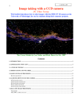
CCD Camera Operating Manual
for the
Model ST-4X, ST-5 and ST-6
Santa Barbara Instrument Group
1482 East Valley Road
Santa Barbara, CA 93108
Phn (805) 969-1851
Fax (805) 969-4069
Note: This equipment has been tested and found to comply with the limits for a Class B digital
device pursuant to Part 15 of the FCC Rules. These limits are designed to provide reasonable
protection against harmful interference in a residential installation. This equipment generates,
uses, and can radiate radio frequency energy and if not installed and used in accordance with
the instructions, may cause harmful interference to radio communications. However, there is
no guarantee that interference will not occur in a particular installation. If this equipment does
cause harmful interference to radio or television reception, which can be determined by turning
the equipment off and on, the user is encouraged to try to correct the interference by one or
more of the following measures:
•
•
•
•
Reorient or relocate the receiving antenna.
Increase the separation between the receiver and the equipment.
Connect the equipment into an outlet on a circuit different from that to which the
receiver is connected.
Consult the dealer or an experienced radio/TV technician for help.
Changes or modifications not expressly approved by the party responsible for compliance could
void the user's authority to operate the equipment.
Also note that user must use shielded interface cables in order to maintain product within FCC
compliance.
CCDOPS Manual
Revision 2A
January 1996
Table of Contents
1.
1.1.
1.2.
Introduction ............................................................................................................1
Road Map of the Documentation ............................................................................1
Quick Tour...............................................................................................................1
1.2.1. CCDOPS Software .................................................................................1
1.2.2. CCD Camera..........................................................................................2
2.
2.1.
2.2.
Introduction to CCD Cameras................................................................................3
Cameras in General..................................................................................................3
How CCD Detectors Work ......................................................................................3
2.2.1. The ST-4X CCD and Frame Transfer CCDs...........................................4
Camera Hardware Architecture ..............................................................................5
CCD Special Requirements......................................................................................7
2.4.1. Cooling...................................................................................................7
2.4.2. Readout Types .......................................................................................8
2.4.3. Dark Frames...........................................................................................8
2.4.4. Flat Field Images....................................................................................8
2.4.5. Pixels vs. Film Grains.............................................................................9
Electronic Imaging ...................................................................................................9
Black and White vs. Color...................................................................................... 10
2.3.
2.4.
2.5.
2.6.
3.
3.1.
3.2.
3.3.
3.4.
3.5.
3.6.
3.7.
3.8.
3.9.
At the Telescope with a CCD Camera ................................................................. 13
Step by Step with a CCD Camera.......................................................................... 13
Attaching the Camera to the Telescope................................................................. 13
Establishing a Communications Link.................................................................... 15
Focusing the CCD Camera .................................................................................... 15
Finding and Centering the Object.......................................................................... 17
Taking an Image .................................................................................................... 17
Displaying the Image............................................................................................. 17
Processing the Image ............................................................................................. 17
Advanced Capabilities........................................................................................... 18
3.9.1. Crosshairs Mode (Photometry and Astrometry)................................. 18
3.9.2. Sub-Frame Readout in Focus............................................................... 18
3.9.3. Track and Accumulate......................................................................... 19
3.9.4. Autoguiding......................................................................................... 19
3.9.5. Auto Grab ............................................................................................ 20
3.9.6. Color Imaging ...................................................................................... 20
4.
4.1.
4.2.
4.3.
4.4.
4.5.
Camera Hardware ................................................................................................. 21
System Components .............................................................................................. 21
Connecting the Power............................................................................................ 21
Connecting to the Computer ................................................................................. 22
Connecting the Relay Port to the Telescope .......................................................... 23
Modular Family of CCD Cameras ......................................................................... 26
5.
5.1.
Camera Software Reference ................................................................................. 31
Different Host Computers ..................................................................................... 31
5.1.1. Installing the Software......................................................................... 31
5.1.2. The CCDOPS User Interface................................................................ 32
5.1.3. CCDOPS for IBM PCs.......................................................................... 35
i
5.2.
6.
6.1.
6.2.
6.3.
6.4.
6.5.
6.6.
6.7.
6.8.
Command Mode.................................................................................. 35
Graphics Mode..................................................................................... 36
5.1.4. CCDOPS on Macintosh Computers .................................................... 37
CCDOPS Menus and Commands.......................................................................... 37
5.2.1. Command Tree .................................................................................... 37
5.2.2. File Menu on the Macintosh ................................................................ 39
5.2.3. File Menu on the PC ............................................................................ 40
Save FITS Command............................................................................ 41
Save TIFF Command ........................................................................... 42
5.2.4. Edit Menu on the Macintosh ............................................................... 43
5.2.5. Camera Menu ...................................................................................... 44
Grab Command ................................................................................... 45
Auto Grab Command .......................................................................... 46
Focus Command.................................................................................. 47
Macintosh Focus Window ................................................................... 49
PC Focus Mode Menus ........................................................................ 50
ST-4X Camera Setup Command.......................................................... 51
ST-5 Camera Setup Command ............................................................ 52
ST-6 Camera Setup Command ............................................................ 53
5.2.6. Display Menu on the Macintosh.......................................................... 54
5.2.7. Display Menu on the PC...................................................................... 55
Display Image Command.................................................................... 56
PC Display Mode Menus..................................................................... 57
Macintosh Contrast Window............................................................... 59
Macintosh Color Table Editor.............................................................. 60
5.2.8. Utility Menu......................................................................................... 61
Edit Parameters Command.................................................................. 63
5.2.9. Misc Menu ........................................................................................... 64
Mac Setup Command .......................................................................... 65
PC Setup Command ............................................................................ 66
Telescope Setup Command ................................................................. 67
5.2.10. Track Menu.......................................................................................... 68
Track and Accumulate Command....................................................... 69
Calibrate Track Command................................................................... 70
Tracking Parameters Command.......................................................... 71
5.2.11. Filter Menu........................................................................................... 73
Filter Setup Command......................................................................... 74
Advanced Imaging Techniques ........................................................................... 75
Lunar and Planetary Imaging................................................................................ 75
Deep Sky Imaging.................................................................................................. 75
Terrestrial Imaging ................................................................................................ 76
Taking a Good Flat Field ....................................................................................... 76
Building a Library of Dark Frames........................................................................ 76
Changing the Camera Resolution.......................................................................... 77
Making Astrometric and Photometric Measurements .......................................... 77
6.7.1. Astrometric Measurements.................................................................. 77
6.7.2. Photometric Measurements. ................................................................ 79
6.7.3. Calculation of Centroids...................................................................... 80
6.7.4. Calculation of Separation..................................................................... 81
6.7.5. Calculation of Magnitude.................................................................... 81
6.7.6. Calculation of Diffuse Magnitude ....................................................... 82
Flat Fielding Track and Accumulate Images......................................................... 82
ii
6.9.
6.10.
Tracking Functions ................................................................................................ 84
PC COM Port Compatibility Testing..................................................................... 85
7.
7.1.
7.2.
7.3.
7.4.
7.5.
Accessories for your CCD Camera....................................................................... 87
Tri-color Imaging ................................................................................................... 87
Camera Lens Adapters and Eyepiece Projection................................................... 87
Focal Reducers ....................................................................................................... 87
Third Party Products and Services ........................................................................ 87
7.4.1. Windows Software............................................................................... 87
7.4.2. Image Processing Software.................................................................. 88
7.4.3. Getting Hardcopy ................................................................................ 88
SBIG Technical Support......................................................................................... 88
8.
Common Problems ............................................................................................... 89
9.
Glossary................................................................................................................. 93
A.1.
A.2.
A.3.
Appendix A - Connector Pinouts ......................................................................... 97
Using RS422 on the PC .......................................................................................... 98
SBIG Tracking Interface Cable (TIC) ..................................................................... 98
B.
B.1.
Appendix B - SBIG File Formats.......................................................................... 99
SBIG Image Formats .............................................................................................. 99
B.1.1 Type 3 Format...................................................................................... 99
B.1.2. Image Compression ........................................................................... 101
PC Color Table Formats....................................................................................... 102
TIFF Format ......................................................................................................... 103
FITS Format.......................................................................................................... 103
B.2.
B.3.
B.4.
C.
C.1.
C.2.
C.3.
Appendix C - Maintenance................................................................................. 105
Replacing the Fuse............................................................................................... 105
Cleaning the CCD and the Window.................................................................... 105
C.2.1 Cleaning the ST-4X and ST-5 ............................................................. 105
C.2.2 Cleaning the ST-6............................................................................... 105
Replacing the Desiccant in the ST-6..................................................................... 106
D.
Appendix D - Cross Platform Compatibility .................................................... 107
iii
Section 1 - Introduction
1.
Introduction
Congratulations and thank you for buying one of Santa Barbara Instrument Group's CCD
cameras. The model ST-4X, ST-5 and ST-6 represent the state of the art in CCD camera systems
with their low noise and advanced capabilities. We feel that these cameras will expand your
astronomy experience by being able to easily take images like the ones you've seen in books and
magazines, but never seen when peeking through the eyepiece. SBIG CCD cameras offer
convenience, high sensitivity (a typical deep-sky image is only two to ten minutes), and
advanced image processing techniques that film just can't match. While CCDs will probably
never replace film in its large format, CCDs allow a wide range of scientific measurements and
have established a whole new field of Astronomy that is growing by leaps and bounds.
1.1.
Road Map of the Documentation
This manual describes the ST-4X, ST-5, and ST-6 CCD Camera Systems from Santa Barbara
Instrument Group. For new users to the field of CCD Astronomy, Sections 2, 3 and 4 offer
introductory material about CCD Cameras and their uses in Astronomy. Users who are
familiar with CCD cameras may wish to skip section 2 and browse through sections 3 and 4,
reading any new material.
Thoroughly experienced SBIG customers may wish to jump right into section 5 which
gives detailed and specific information about the SBIG software. This section is written more as
a reference than as general reading. Sections 6 and 7 offer hints and information about
advanced imaging techniques and accessories for CCD imaging that you may wish to read after
your initial telescope use of the CCD camera. Finally, section 8 may be helpful if you experience
problems with your camera, and the Appendices provide a wealth of technical information
about these systems.
1.2.
Quick Tour
This section is a quick guided tour of the CCD Camera System you have just purchased. If
you're like most people you want to get started right away and dispense with the manual. Use
this section as a guide for learning about your new system.
1.2.1. CCDOPS Software
Follow the instructions below to run the CCDOPS software and display and process sample
images included on the distribution diskette.
•
For this quick tour you can run the CCDOPS software from the distribution
floppy disk or you can install the software on our hard disk (refer to Section
5.1.1).
•
On the Macintosh you can double-click on the CCDOPS icon. On the PC you
should make the CCDOPS floppy or directory the active directory then give
DOS the CCDOPS command.
•
Use the Open command in the File menu to load one of the sample images.
•
On the Macintosh the image is displayed automatically. On the PC you then
use the Image command in the Display menu to display the image.
Page 1
Section 1 - Introduction
•
Try using the crosshairs. On the Macintosh use the Show Crosshairs
command in the Display menu. On the PC hit the 'X' key. Use the mouse or
arrow keys to move the crosshair around in the image and see the pixel
values.
•
Quit the crosshairs and try inverting the image. On the Macintosh you check
the Invert checkbox and then click the Do It button in the Contrast window.
On the PC you hit the Esc key to quit the Crosshairs mode, then hit the 'N'
key.
•
Try the photo display mode. On the Macintosh use the Photo Mode
command in the Display Menu. On the PC you exit the display mode by
hitting the Esc key and then use the Display Image command again, this time
selecting the Photo Display mode instead of the Analysis mode.
•
Load up the other sample images and display them using the photo display
mode.
1.2.2. CCD Camera
Unfortunately there really aren't many shortcuts you can take when using the CCD camera to
capture images. The instructions below refer you to various sections of the manual.
•
Insert the CCD Camera into the telescope and focus on a star (refer to
Sections 3.2 and 3.3).
•
Find some relatively bright object like M51, the Ring Nebula (M57) or the
Dumbbell Nebula (M27) (refer to section 3.5).
•
Take a 2 minute exposure using the Grab command with the Dark frame
option set to Also (refer to Section 3.6).
•
Display the image (refer to Section 3.7).
•
Process the image (refer to Section 3.8).
If you happen to have purchased a camera lens adapter for your CCD Camera you can use that
to take images in the daytime. Additionally you could make a small pin-hole aperture out of a
piece of aluminum foil after wrapping it around the camera's nosepiece.
•
Shut down the f stop all the way to f/16 or f/22.
•
Set the focus based upon the object and the markings on the lens.
•
Take a 1 second exposure with the Grab command.
•
Display the image (refer to Section 3.7).
•
Process the image (refer to Section 3.8).
Page 2
Section 2 - Introduction to CCD Cameras
2.
Introduction to CCD Cameras
This section introduces new users to CCD (Charge Coupled Device) cameras and their
capabilities and to the field of CCD Astronomy and Electronic Imaging.
2.1.
Cameras in General
The CCD is very good at the most difficult astronomical imaging problem: imaging small, faint
objects. For such scenes long film exposures are typically required. The CCD based system has
several advantages over film: greater speed, quantitative accuracy, ability to increase contrast
and subtract sky background with a few keystrokes, the ability to co-add multiple images
without tedious dark room operations, wider spectral range, and instant examination of the
images at the telescope for quality. Film has the advantages of a much larger format, color, and
independence of the wall plug (the SBIG family of cameras can be battery operated in
conjunction with a laptop computer, though). After some use you will find that film is best for
producing sensational large area color pictures, and the CCD is best for planets, small faint
objects, and general scientific work such as variable star monitoring and position determination.
It is for this reason that we designed our cameras to support both efforts, as a stand-alone
tracker, in the case of the ST-4, and as a tracker/imaging camera in the case of the other SBIG
CCD products.
2.2.
How CCD Detectors Work
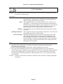
The basic function of the CCD detector is to convert an incoming photon of light to an electron
which is stored in the detector until it is read out, thus producing data which your computer
can display as an image. It doesn't have to be displayed as an image. It could just as well be
displayed as a spreadsheet with groups of numbers in each cell representing the number of
electrons produced at each pixel. These numbers are displayed by your computer as shades of
gray for each pixel site on your screen thus producing the image you see. How this is
accomplished is eloquently described in a paper by James Janesick and Tom Elliott of the Jet
Propulsion Laboratory:
"Imagine an array of buckets covering a field. After a rainstorm, the buckets are
sent by conveyor belts to a metering station where the amount of water in each
bucket is measured. Then a computer would take these data and display a
picture of how much rain fell on each part of the field. In a CCD the "raindrops"
are photons, the "buckets" the pixels, the "conveyor belts" the CCD shift registers
and the "metering system" an on-chip amplifier.
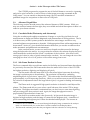
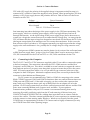
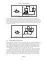
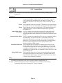
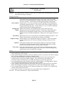
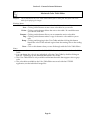
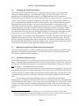
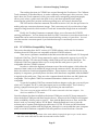
Technically speaking the CCD must perform four tasks in generating an image.
These functions are 1) charge generation, 2) charge collection, 3) charge transfer,
and 4) charge detection. The first operation relies on a physical process known
as the photoelectric effect - when photons or particles strikes certain materials
free electrons are liberated...In the second step the photoelectrons are collected in
the nearest discrete collecting sites or pixels. The collection sites are defined by
an array of electrodes, called gates, formed on the CCD. The third operation,
charge transfer, is accomplished by manipulating the voltage on the gates in a
systematic way so the signal electrons move down the vertical registers from one
pixel to the next in a conveyor-belt like fashion. At the end of each column is a
horizontal register of pixels. This register collects a line at a time and then
Page 3
Section 2 - Introduction to CCD Cameras
transports the charge packets in a serial manner to an on-chip amplifier. The
final operating step, charge detection, is when individual charge packets are
converted to an output voltage. The voltage for each pixel can be amplified offchip and digitally encoded and stored in a computer to be reconstructed and
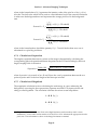
displayed on a television monitor."1
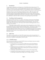
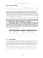
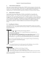
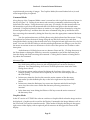
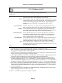
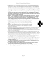
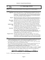
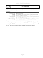
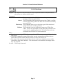
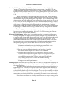
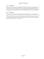
Output
Readout Register
Y=1
Amplifier
Y=N
X=1
X=M
Figure 2.1 - CCD Structure
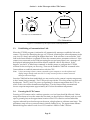
2.2.1. The ST-4X CCD and Frame Transfer CCDs
In the ST-4X, the CCD is read out electronically by shifting each row of pixels into a readout
register at the Y=0 position of the CCD, and then shifting the row out through an amplifier at
the X=0 position. The entire array shifts up one row when a row is shifted into the readout
register, and a blank row is inserted at the Y=164 position. Note that the CCD elements are still
collecting light as they step up to the readout register.
The ST-5 and ST-6 CCD cameras use a more advanced CCD which is known as a frame
transfer CCD. In these devices all active pixels are shifted very quickly into a pixel array
screened from the light by a metal layer, and then read out. The ST-4X CCD minimizes the
effect of not having a frame transfer buffer by reading out the array relatively quickly, reading
30,000 pixels in about 0.7 seconds. As long as the CCD exposure is greater than about one
second this technique will reduce streaking of the stars to acceptable levels.
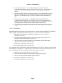
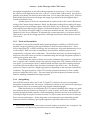
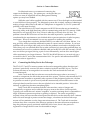
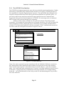
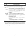
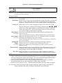
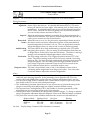
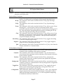
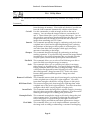
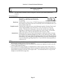
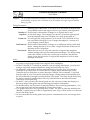
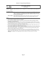
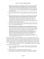
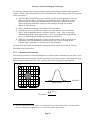
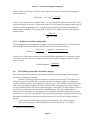
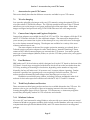
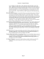
Planets pose a particular problem to the ST-4X CCD since they are so bright that
exposures of 1 second at f/10 are badly overexposed. The ST-4X has a "Half Frame" mode for
planets and bright stars to solve this problem. In the Half Frame mode the upper half of the
CCD is used as a frame buffer for a bright object positioned in the lower half of the CCD as
shown below in Figure 2.2. A short exposure can be taken and the bottom half of the array
shifted rapidly up to the upper half. The 82 lines of short exposure data can then be readout at
the normal rate. This method works quite well, and uses enough pixels such that 0.5 arcsecond
per pixel scale factors can be achieved while viewing an entire planet.
1
"History and Advancements of Large Area Array Scientific CCD Imagers", James Janesick, Tom
Elliott. Jet Propulsion Laboratory, California Institute of Technology, CCD Advanced Development
Group.
Page 4
Section 2 - Introduction to CCD Cameras
Figure 2.2 - ST-4X Half Frame Positioning
When using the original ST-4 for a long exposure, a glow was present in the upper left corner of
the image, near pixel (1,1). This was due to an electrical luminescence in the readout electronics
that could saturate the array in the corner in exposures several minutes long. This glow has
been essentially eliminated in the ST-4X.
2.3.
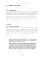
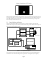
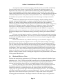
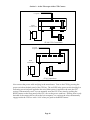
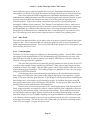
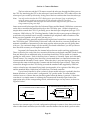
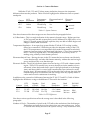
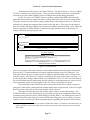
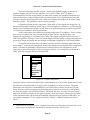
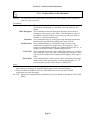
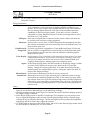
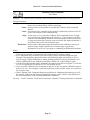
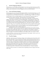
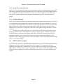
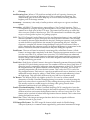
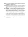
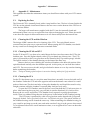
Camera Hardware Architecture
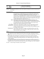
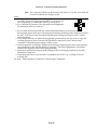
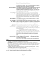
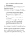
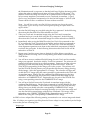
This section describes the SBIG CCD camera from a systems standpoint. It describes the
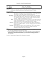
elements that comprise a CCD camera and the functions they provide. Please refer to Figure 2.3
below as you read through this section.
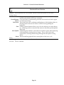
Clock
Drivers
Postamp/
A/D
Converter
Frame
Store
Optical
Head
CCD
Preamp
TE Cooler
Microcontroller
Host Computer
Power
Supply
CPU
RS232
Figure 2.3 - CCD System Block Diagram
At the "front end" of any CCD camera is the CCD sensor itself. As we have already learned,
CCD detectors are a solid state image sensor organized in a rectangular array of regularly
Page 5
Section 2 - Introduction to CCD Cameras
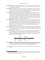
spaced rows and columns. Table 2.1 below lists some interesting aspects of the various CCDs
used in the ST-4X, ST-5 and ST-6 cameras.
Camera
ST-4X
ST-5
ST-6
CCD
TC211
TC255
TC241
Array
Number of
Dimensions
Pixels
2.6 x 2.6 mm
192 x 164
3.2 x 2.4 mm
320 x 240
8.6 x 6.5 mm
375 x 242
Table 2.1 - Camera CCD Configurations
Pixel Sizes
13.75 x 16 µ
10 x 10 µ
23 x 27 µ
The CCD is cooled by mounting it on the cold side of a thermoelectric (TE) cooler. The TE
cooler pumps heat out of the CCD with its own internally generated heat and dissipates it into a
heat sink which forms part of the optical head's mechanical housing. In SBIG cameras this
waste heat is dumped into the air using passive radiators, making the design and operation of
the heads simple and not inconvenienced by requirements for liquid recirculation cooling.
Since the CCD is cooled below 0°C, some provision must be made to prevent frost from
forming on the CCD. SBIG cameras have the CCD/TE Cooler mounted in a windowed
hermetic chamber sealed with an O-Ring. The hermetic chamber does not need to be evacuated,
another "ease of use" feature we employ in the design of our Optical heads. Keeping the size of
the hermetic chamber small (in the case of the ST-4X and ST-5) or using desiccant in the
chamber (ST-6) keeps the total amount of moisture that can condense small.
Other elements contained in the optical head include the preamplifier and an
electromechanical vane (in the case of the ST-6). The vane makes taking dark frames a simple
matter of pushing a button on the computer. We refer to this as a vane rather than a shutter
because it does not perform the task of timing the exposure, it merely blocks the light from the
CCD to facilitate taking dark images. Timing of exposures in SBIG cameras is based upon the
clocking scheme applied to the CCDs.
As far as the ST-4X and ST-5 are concerned, that's all of the system components
contained in the optical head unit, owing to its small size. The Clock Drivers and the PostAmp/Analog to Digital Converter reside in different places in the ST-4X/ST-5 and the ST-6.
The Clock Drivers adapt the logic-level signals from the CPU's microcontroller to the voltage
levels and sequences required by the CCD. Clocking the CCD transfers charge in the array and
is used to clear the array or read it out. The Postamp further amplifies and conditions the
CCD's output signal for digitization by the Analog to Digital Converter (A/D). In the ST-6 both
the clock drivers and the A/D are contained on a board in the optical head. In the ST-4X and
ST-5 these electronics are on a board in the lower half of the CPU.
This leaves to be discussed only the elements in the CPU, namely the Microcontroller,
the Frame Store, and the Power Supply. The microcontroller is a 9.2 MHz 80188
microcontroller, based upon the 8088 microprocessor used in the IBM PC. It controls the
operation of the CCD camera at the lowest level, receiving commands from the Host Computer
and executing sequences of instructions to control and acquire images. The frame store allows
holding three images in the CPU (a light image, a dark image, and a double-precision
accumulation image). Finally, the power supply takes the supplied 12 Volts and produces the
various regulated voltages required by the CPU in addition to a variable output supply for
powering the TE Cooler.
Although not part of the CCD Camera itself, the Host Computer and Software are an
integral part of the system. SBIG provides software for its cameras that support both the IBM
Page 6
Section 2 - Introduction to CCD Cameras
PC (and Compatible) and Macintosh computers. The software allows image acquisition, image
processing, and auto guiding with ease of use and professional quality. Many man-years and
much customer feedback has gone into the SBIG software and it is unmatched in its capabilities.
2.4.
CCD Special Requirements
This section describes the unique features of CCD cameras and the special requirements that
CCD systems impose.
2.4.1. Cooling
Random noise and dark current combine to place a lower limit on the ability of the CCD to
detect faint light sources. If the CCD is producing more electrons from its own internal
processes than is produced by photons from a distant object, the signal from the object is said to
be "lost in the noise", and will be impossible to display without sophisticated image processing
software. The same is true if the immediate environment is producing the noise. There are
several sources of noise, both internal and external which can contribute to this problem. Noise
here refers to the "gritty" look of short exposure images.
Internally, the CCD generates thermal noise and readout noise caused by the operation
of the electronics on the chip. In unusual circumstances, radio frequency interference can
contaminate the CCD just as it can affect your television set or radio, but this is rarely a problem
in normal operating environments. Power lines, switches turning on and off, spark plugs, even
cosmic rays will register if conditions are right. Of course, there is one external source of "noise"
you do not want to eliminate - the photons coming from the object you are imaging! So the trick
is to eliminate unwanted sources of electron production in the chip and thus make the detector
more sensitive to the remaining source of electron production by incoming photons. As you
can imagine, the reduction of unwanted noise is important for the best performance of the CCD.
The user will naturally have to do his or her best to reduce external sources of noise in the
environment. The internal noise of SBIG cameras is kept to an absolute minimum by using state
of the art technology.
Dark current is thermally generated electrons in the device itself. All CCDs have dark
current which can cause each pixel to fill with electrons in only a few seconds at room
temperature even in the absence of light. By cooling the CCD, this source of noise is reduced,
the sensitivity increased, and longer exposures are possible. In fact, for every 8°C of additional
cooling, the dark current in the CCD is reduced to half. All SBIG cameras use a thermoelectric
(TE) cooler to cool the CCD. The ST-4X and ST-5 have a single stage cooler whereas the larger
format ST-6 utilizes a two stage cooler. The ST-5 and ST-6 have temperature sensing
thermistors on the CCD mount to monitor the temperature, and the CPU controls the
temperature at a user determined value for long periods. As a result, exposures hours long are
possible, and saturation of the CCD by the sky background typically limits the exposure time.
The temperature regulation feature of the ST-5 and ST-6 also means that one dark frame can be
used for similar exposures on several nights.
The sky background conditions also increase the noise in images, and in fact, as far as
the CCD is concerned, there is no difference between the noise caused by dark current and that
from sky background. If your sky conditions are causing photoelectrons to be generated at the
rate of 100 e-/pixel/sec for example, increasing the cooling beyond the point where the dark
current is roughly half that amount will not improve the quality of the image. This very reason
Page 7
Section 2 - Introduction to CCD Cameras
is why deep sky filters are so popular with astrophotography. They reduce the sky background
level, increasing the contrast of dim objects.
2.4.2. Readout Types
In order to read out the values of the charge stored in the pixels as they are shifted to the
readout amplifiers, the charge is stored temporarily on a capacitor. This capacitor converts the
optically generated charge to a voltage level for the output amplifier to sense. When the
readout process for the previous pixel is completed, the capacitor is drained and the next charge
shifted, read, and so on. However, each time the capacitor is drained, some residual charge
remains.
This residual charge is actually the dominant noise source in CCD readout electronics.
This residual charge may be measured before the next charge is shifted in, and the actual
difference calculated. This is called double correlated sampling. It produces more accurate data
at the expense of longer read out times (two measurements are made instead of one). If the
accuracy of the data is not critical, as in finding objects or focusing, the extra time spent in
double correlated sampling is not necessary. In this case a rapid readout mode may be
available which ignores the small residual charge.
2.4.3. Dark Frames
No matter how much care is taken to reduce all sources of unwanted noise, some will remain.
Fortunately, however, due to the nature of electronic imaging and the use of computers for
storing and manipulating data, this remaining noise can be drastically reduced by the
subtraction of a dark frame from the raw light image. A dark frame is simply an image taken at
the same temperature and for the same duration as the light frame with the source of light to
the CCD blocked so that you get a "picture" of the dark. This dark frame will contain an image
of the noise caused by dark current (thermal noise) and other fixed pattern noise such as read
out noise. When the dark frame is subtracted from the light frame, this pattern noise is
removed from the resulting image.
2.4.4. Flat Field Images
Another way to compensate for certain unwanted optical effects is to take a "flat field image"
and use it to correct for variations in pixel response uniformity across the area of your darksubtracted image. You take a flat field image of a spatially uniform source and use the
measured variations in the flat field image to correct for the same unwanted variations in your
images. The Flat Field command allows you to correct for the effects of vignetting and
nonuniform pixel responsivity across the CCD array.
The Flat Field command is very useful for removing the effects of vignetting that may
occur when using a field compression lens. It is difficult to visually tell the difference between
a corrected and uncorrected image if there is little vignetting, so you must decide whether to
take the time to correct any or all of your dark-subtracted images. It is however always
recommended for images that are intended for accurate photometric measurements.
Page 8
Section 2 - Introduction to CCD Cameras
2.4.5. Pixels vs. Film Grains
Resolution of detail is determined, to a certain degree, by the size of the pixel in the detector
used to gather the image, much like the grain size in film. The pixel size of the detector in the
ST-4X is 13.75 x 16 microns (1 micron = 0.001mm ≈ 0.04 mil). In the ST-5 the pixels are 10 x 10
microns. In the ST-6 the pixels are 23 x 27 microns. Film grain ranges from several hundredths
of a micron to several microns depending on the film speed and quality of the emulsion.
However, the effects of seeing are probably the limiting factor in any good photograph or
electronic image. For example, on a perfect night with excellent optics an observer might hope
to achieve sub-arcsecond seeing. More often, however, with the average night sky and even
very good optics, seeing may be limited to several arcseconds and you would probably be very
satisfied with seeing of one or two arcseconds.
Using an ST-5 camera with 10 micron pixels, an 8" f/10 telescope will produce a single
pixel angular subtense of one arcsecond, seeing permitting. A 10" f/3 telescope will produce
images of 2.6 arcseconds per pixel. If, however, seeing affects the image by limiting resolution
to 3 arcseconds, then you would be hard pressed to see any resolution difference between the
larger and smaller pixels as you are mostly limited by the sky conditions.
Another important consideration is the field of view of the camera. For instance, while
the ST-5 has smaller pixels than the ST-6, its area is also smaller, resulting in a corresponding
smaller field of view at a given focal length. For comparison, the diagonal measurement of a
frame of 35mm film is approximately 40mm, whereas the diagonal dimension of the ST-5 chip is
approximately 4mm. The relative CCD sizes for each camera and their corresponding field of
view in an 8" f/10 telescope are given below:
Camera
ST-4X
ST-5
ST-6
35mm
Array Dimensions
Diagonal
Field of View at 8" f/10
2.64 x 2.64 mm
3.73 mm
4.5 x 4.5 arcminutes
3.20 x 2.40 mm
4.00 mm
5.6 x 4.2 arcminutes
8.63 x 6.53 mm
10.8 mm
14.6 x 11 arcminutes
36 x 24 mm
43 mm
62 x 42 arcminutes
Table 2.2 - CCD Array Dimensions
A subtle effect is that, at the same focal length, larger pixels collect more light from nebular
regions than small ones, reducing the noise at the expense of resolution.
2.5.
Electronic Imaging
Electronic images resemble photographic images in many ways. Photographic images are made
up of many small particles or grains of photo sensitive compounds which change color or
become a darker shade of gray when exposed to light. Electronic images are made up of many
small pixels which are displayed on your computer screen to form an image. Each pixel is
displayed as a shade of gray, or in some cases a color, corresponding to a number which is
produced by the electronics and photo sensitive nature of the CCD camera. However,
electronic images differ from photographic images in several important aspects. In their most
basic form, electronic images are simply groups of numbers arranged in a computer file in a
particular format. This makes electronic images particularly well suited for handling and
manipulation in the same fashion as any other computer file.
Page 9
Section 2 - Introduction to CCD Cameras
An important aspect of electronic imaging is that the results are available immediately.
Once the data from the camera is received by the computer, the resulting image may be
displayed on the screen at once. While Polaroid cameras also produce immediate results,
serious astrophotography ordinarily requires hypersensitized or cooled film, a good quality
camera, and good darkroom work to produce satisfying results. The time lag between exposure
of the film and production of the print is usually measured in days. With electronic imaging,
the time between exposure of the chip and production of the image is usually measured in
seconds.
Another very important aspect of electronic imaging is that the resulting data are
uniquely suited to manipulation by a computer to bring out specific details of interest to the
observer. In addition to the software provided with the camera, there are a number of
commercial programs available which will process and enhance electronic images. Images may
be made to look sharper, smoother, darker, lighter, etc. Brightness, contrast, size, and many
other aspects of the image may be adjusted in real time while viewing the results on the
computer screen. Two images may be inverted and electronically "blinked" to compare for
differences, such as a new supernova, or a collection of images can be made into a large mosaic.
Advanced techniques such as maximum entropy processing will bring out otherwise hidden
detail.
Of course, once the image is stored on a computer disk, it may be transferred to another
computer just like any other data file. You can copy it or send it via modem to a friend, upload
it to your favorite bulletin board or online service, or store it away for processing and analysis
at some later date.
We have found the best way to obtain a hard copy of your electronic image is to
photograph it directly from the computer screen. You may also send your image on a floppy
disk to a photo lab which has digital photo processing equipment for a professional print of
your file. Make sure the lab can handle the file format you will send them. Printing the image
on a printer connected to your computer is also possible depending on your software/printer
configuration. There are a number of software programs available which will print from your
screen. However, we have found that without specialized and expensive equipment, printing
images on a dot matrix or laser printer yields less than satisfactory detail. However, if the
purpose is simply to make a record or catalog the image file for easy identification, a dot matrix
or laser printer should be fine.
2.6.
Black and White vs. Color
The first and most obvious appearance of a CCD image is that it is produced in shades of gray,
rather than color. The CCD chip used in SBIG cameras itself is color blind and the pixel values
that the electronics read out to a digital file are only numbers representing the number of
electrons produced when photons of any wavelength happen to strike its sensitive layers.
Of course, there are color video cameras, and a number of novel techniques have been
developed to make the CCD chip "see" color. The most common way implemented on
commercial cameras is to partition the pixels into groups of three, one pixel in each triplet
"seeing" only red, green or blue light. The results can be displayed in color. The overall image
will suffer a reduction in resolution on account of the process. A newer and more complicated
approach in video cameras has been to place three CCD chips in the camera and split the
incoming light into three beams. The images from each of the three chips, in red, green and
Page 10
Section 2 - Introduction to CCD Cameras
blue light is combined to form a color image. Resolution is maintained. For normal video
modes, where there is usually plenty of light and individual exposures are measured in small
fractions of a second, these techniques work quite well. However, for astronomical work,
exposures are usually measured in seconds or minutes. Light is usually scarce. Sensitivity and
resolution are at a premium. The most efficient way of imaging under these conditions is to
utilize all of the pixels, collecting as many photons of any wavelength, as much of the time as
possible.
In order to produce color images in astronomy, the most common technique is to take
three images of the same object using a special set of filters and then recombine the images
electronically to produce a color composite or RGB color image. SBIG offers as an option a color
filter wheel. The accessory is inserted between the telescope and the CCD head. An object is
then exposed using a red filter. The wheel is turned until the green filter is in place and another
image is taken. Finally a blue image is taken. When all three images have been saved, they may
be merged into a single color image using SBIG or third party color software.
Page 11
Section 3 - At the Telescope with a CCD Camera
3.
At the Telescope with a CCD Camera
This section describes what goes on the first time you take your CCD camera out to the
telescope. You should read this section throughout before working at the telescope. It will help
familiarize you with the overall procedure that is followed without drowning you in the details.
It is recommended you first try operating the camera in comfortable surroundings to learns its
operation.
3.1.
Step by Step with a CCD Camera
In the following sections we will go through the steps of setting up and using your CCD
camera. The first step is attaching the camera to the telescope. The next step is powering up the
camera and establishing a communication link to you computer. Then you will want to get in
focus, find an object and take an image. Once you have your light image with a dark frame
subtracted, you can display the image and process the results to your liking. Each of these steps
is discussed in more detail below.
3.2.
Attaching the Camera to the Telescope
All SBIG cameras are similar in configuration. The CCD head attaches to the telescope by
slipping into the eyepiece holder. A fifteen foot cable runs from the head to the CPU box, which
is usually on the ground near the telescope. A ten foot cable connects the host computer's serial
port to the CPU box. The CPU is powered by a wall transformer although operation from a car
battery is possible.
Important Note:
Never connect or disconnect the CCD head from the CPU box unless the power
switch on the rear side of the CPU box is turned OFF. Damage to the CCD head,
or the CPU could occur.
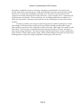
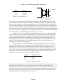
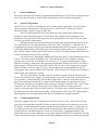
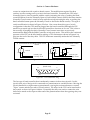
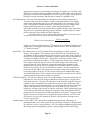
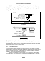
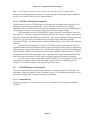
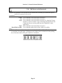
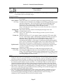
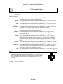
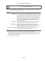
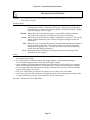
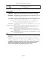
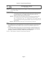
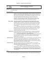
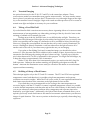
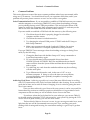
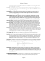
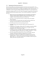
Referring to Figure 3.1 below, connect the CCD head to the CPU connector marked "CCD
HEAD" with the supplied cable. Next, connect the serial cable to the COM connector along the
same front panel of the CPU box and connect the opposite end to the serial port of your
computer.
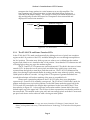
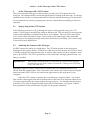
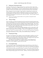
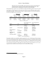
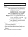
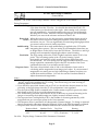
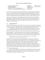
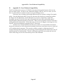
Insert the CCD Camera's nosepiece into your telescope's eyepiece holder. You should
fully seat the camera against the end of the draw tube so that once focus has been achieved you
can swap out and replace the camera without having to refocus. You should orient the camera
so that the CCD's axes are aligned in Right Ascension and Declination. Use Figure 3.2 below
showing the back of the optical heads as a guide for the proper orientation.
Page 13
Section 3 - At the Telescope with a CCD Camera
To Host
Computer
POWER RELAYS
COM
AUX
CCD HEAD
Wall
Transformer
CCD HEAD
JUMPER
ST-4X/ST-5 Connections
To Host
Computer
POWER RELAYS
COM
AUX
CCD HEAD
Wall
Transformer
ST-6 Connections
Figure 3.1 - CPU Connections
Next connect the power cable and plug in the transformer. Turn on the CPU by pressing the
power switch on the back panel of the CPU box. The red LED in the power switch should glow
indicating power has been applied to the unit. When power is applied to the unit, the CPU
section is automatically reset. You can manually reset the CPU at any time by pushing the
RESET button on the front panel of the CPU, next to the power connector. Pushing reset is only
desirable if the camera fails to talk to the host computer. You can hear the relays momentarily
engage inside the CPU box with a 'click' when you push in the RESET button.
Page 14
Section 3 - At the Telescope with a CCD Camera
RA
RA
DEC
DEC
ST-4X/ST-5 Orientation
ST-6 Orientation
Figure 3.2 Orientation of the Optical Head Viewed from Back
3.3.
Establishing a Communications Link
When the CCDOPS program is initiated it will automatically attempt to establish a link to the
camera. This involves identifying the type of CCD head, initializing the offset adjustment in the
case of an ST-6 head, and seeking the highest Baud rate. If the software is successful the "Link"
field in the Status Window is updated to show the communications parameters achieved. If the
camera is not connected or the COM port setting has not yet been properly set, a message will
be displayed indicating that the software failed to establish a link to the camera. If this
happens, use the PC or Mac Setup command in the Misc menu to configure the CCDOPS
software for the serial port you are using. Then use the Establish COM Link command in the
Camera Menu to establish communications with the CPU.
Note: It is not necessary to have a camera connected to your computer to run the software and
display images already saved onto disk. It is only necessary to have a camera connected
when you take new images.
Once the COM link has been established you may need to set the camera's setpoint temperature
in the Camera Setup command. The ST-4X powers up with the TE cooling turned on which will
be adequate. The ST-5 and ST-6 power up regulating to whatever temperature the CCD is at
which in this case will be the ambient temperature. Use the Camera Setup command and
choose a setpoint temperature approximately 40°C below the ambient temperature.
3.4.
Focusing the CCD Camera
Focusing a CCD camera can be a tedious operation, so a few hints should be followed. Before
using the software to focus the camera the first time you should place a diffuser (such as scotch
tape or ground glass) at the approximate location of the CCD's sensitive surface behind the
eyepiece tube and focus the telescope on the moon, a bright planet or a distant street lamp. This
preliminary step will save you much time in initially finding focus. The approximate distance
behind the eyepiece tube for each of our CCD cameras is listed in Table 3.1 below:
Page 15
Section 3 - At the Telescope with a CCD Camera
Camera
ST-4X
ST-5
ST-6
Diffuser
Distance
0.040 inch
0.050 inch
0.560 inch
Table 3.1 - Camera Back Focus
Back Focus Distance
from Table 3.1
To find the fine focus, insert the CCD head into the eyepiece tube, taking care to seat it, and
then enter the CCDOPS FOCUS mode. The Focus command automatically displays successive
images on the screen as well as the peak brightness value of the brightest object in the field of
view. Point the telescope at a 5th to 7th magnitude star (you don't want to focus on bright stars
like Sirius because the CCD saturates quickly unless you're way out of focus). If you want, you
can center the image on the computer monitor by fine adjusting the telescope position although
this is not necessary. As long as the star is in the field of view and not so close to the edge that it
will drift out while you are focusing, the positioning is not critical.
An exposure of 1 to 3 seconds is recommended to smooth out some of the atmospheric
effects. While you can use the Full frame mode to focus, the frame rate or screen update rate
can be increased significantly by using Planet mode. In the Planet mode the Focus command
takes a full image and then lets you position a variable sized rectangle around the star. On
subsequent images the Planet mode only digitizes, downloads, and displays the small area you
selected. The increase in frame rate is roughly proportional to the decrease in frame size,
assuming you are using a short exposure.
The telescope focus is best achieved by maximizing the peak value of the star image.
You should be careful to move to a dimmer star if the peak brightness causes saturation. The
saturation levels of the various cameras are shown in Table 3.2 below. Another point you
should also be aware of is that as you approach a good focus, the peak reading can vary by 30%
or so. This is due to the fact that as the star image gets small, where an appreciable percentage
of the light is confined to a single pixel, shifting the image a half a pixel reduces the peak
brightness as the star's image is split between the two pixels.
Camera
ST-4X
ST-5
ST-6
Saturation Counts
16384
16384
65535
Table 3.2 - Saturation Values
Once the best focus is found, the focusing operation can be greatly shortened the second time by
removing the CCD head, being careful not to touch the focus knob. Insert a high power
eyepiece and slide it back and forth to find the best visual focus, and then scribe the outside of
the eyepiece barrel. The next time the CCD is used the eyepiece should be first inserted into the
tube to the scribe mark, and the telescope visually focused and centered on the object. At f/6
the depth of focus is only 0.005 inch, so focus is critical.
Page 16
Section 3 - At the Telescope with a CCD Camera
3.5.
Finding and Centering the Object
Once best focus is achieved, we suggest using the Focus command in "Dim" mode to help
center objects. This mode gives a full field of view, but reduces resolution in order to increase
the digitization and download time. If you have difficulty finding an object after obtaining
good focus, check to be sure that the head is seated at best focus, then remove the head and
insert a medium or low power eyepiece. Being careful not to adjust the focus knob on the
telescope, slide the eyepiece in until the image appears in good focus. Then visually find and
center the object, if it is visible to the eye. If not, use your setting circles carefully. Then, reinsert the CCD head and set an exposure time of about ten seconds. Center the object using the
telescope hand controls.
Note: With a 10 second exposure, objects like M51 or the ring nebula are easily detected with
modest amateur telescopes.
3.6.
Taking an Image
Take a CCD image of the object by selecting the Grab command and setting the exposure time.
Star out with the Image size set to full and Auto Display and Auto contrast enabled. The camera
will expose the CCD for the correct time, and digitize and download the image. One can also
take a dark frame immediately before the light image using the Grab command. In the case of
the ST-4X and ST-5 you are reminded to cover the telescope for the dark frame. In the case of
the ST-6 the dark frame is taken automatically.
Because the ST-5 and ST-6 have regulated temperature control, you may prefer to take
and save separate dark images, building up a library at different temperatures and exposure
times, and reusing them on successive nights. At the start it's probably easiest to just take the
dark frames when you are taking the image. Later, as you get a feel for the types of exposures
and setpoint temperatures you use, you may wish to build this library of dark frames.
3.7.
Displaying the Image
The image can be displayed on the computer screen using the graphics capability of your host
computer. Auto contrast can be selected and the software will pick background and range
values which are usually good for a broad range of images or the background and range values
can be optimized manually to bring out the features of interest.
The image can also be displayed as a negative image, or can be displayed with
smoothing to reduce the graininess. Once displayed, the image can be analyzed using
crosshairs, or can be cropped or zoomed to suit your tastes.
3.8.
Processing the Image
If not done already, images can be dramatically improved by subtracting off a dark frame of
equal exposure for an ST-6. On the ST-4X and ST-5 this effect isn't very dramatic for exposures
shorter than a few seconds. You will typically do this as part of the Grab command although it
can also be done manually using the Dark Subtract command. By subtracting the dark frame,
pixels which have higher dark current than the average, i.e., "hot" pixels, are greatly suppressed
and the displayed image appears much smoother. Visibility of faint detail is greatly improved.
Page 17
Section 3 - At the Telescope with a CCD Camera
The CCDOPS program also supports the use of flat field frames to correct for vignetting
and pixel to pixel variations, as well as a host of other image processing commands in the
Utility menu. You can smooth or sharpen the image, flip it to match the orientation of
published images for comparison or remove hot or cold pixels.
3.9.
Advanced Capabilities
The following sections describe some of the advanced features of SBIG cameras. While you
may not use these features the first night, they are available and a brief description of them is in
order for your future reference.
3.9.1. Crosshairs Mode (Photometry and Astrometry)
Using the crosshair mode2 enables examination of images on a pixel by pixel basis for such
measurements as Stellar and Diffuse Magnitude, and measurement of stellar positions. The 14
to 16 bit accuracy of SBIG systems produces beautiful low-noise images and allows very
accurate brightness measurements to be made. With appropriate filters stellar temperature can
be measured. Section 6.7 gives detailed information about how you use the crosshair mode to
make astrometric and photometric measurements.
In the crosshair mode, you move a small cross shaped crosshair around in the image
using the keyboard or the mouse. As you position the crosshair, the software displays the pixel
value beneath the crosshair and the X and Y coordinates of the crosshair. Also shown is the
average pixel value for a box of pixels centered on the crosshair. You can change the size of the
averaging box from 3x3 to 11x11 pixels to collect all the energy from a star.
3.9.2. Sub-Frame Readout in Focus
The Focus command offers several frame modes for flexibility and increased frame throughput.
As previously discussed, the Full frame mode shows the entire field of view of the CCD with
the highest resolution, digitizing and displaying all pixels.
The Dim mode offers the same field of view but offers higher frame rates by reducing
the image's resolution prior to downloading. The resolution is reduced by combining
neighboring block of pixels into a "super pixel".3 This reduces the download and display times
proportionately, as well improving sensitivity. While you would not want to use the Dim mode
for critical focus adjustments due to the large effective pixel, it is great for finding and centering
objects.
The Planet mode is suggested if high spatial resolution is desired for small objects like
planets. The Planet mode allows you to select a small sub-area of the entire CCD for image
acquisition. The highest resolution is maintained but you don't have to waste time digitizing
and processing pixels that you don't need. Again, the image throughput increase is
proportional to the reduction in frame size.
One final Focus readout mode is the Spot mode. In Spot mode the entire image is
digitized at high resolution, and the image is scanned for the brightest pixel. A small box of
pixels surrounding the brightest pixel is then downloaded and displayed. The increase in
2
3
On the PC the Crosshairs mode is accessed through the Display Image command in the Analysis
mode. On the Macintosh you use the Show Crosshair command in the Display Menu.
The Dim mode combines pixels after they are digitized which is referred to as off-chip binning.
Page 18
Section 3 - At the Telescope with a CCD Camera
throughput is dependent on the camera being used and can range from 2:1 for an ST-6 which
has a slower 16 bit digitization rate to 4:1 on an ST-5 with its faster 14 bit readout. Spot mode is
probably most handy for telescopes that suffer from a lot of image shift during focus. Where as
Planet mode shows the same area image after image, Spot mode tracks the brightest object
around in the field of view.
Another aspect of the Focus command and its various modes is the Camera Resolution4
setting in the Camera Setup command. Briefly, the Resolution setting allows trading off image
resolution (pixel size) and image capture time while field of view is preserved. High resolution
with smaller pixels takes longer to digitize and download than Low resolution with larger
pixels. The cameras all support High, Low and Auto resolution modes. The Auto mode is
optimized for the Focus command. It automatically switches between Low resolution for Full
frame mode to provide fast image acquisition, and High resolution for Planet mode to achieve
critical focus.
3.9.3. Track and Accumulate
An automatic Track and Accumulate mode (patent pending) is available in CCDOPS which
simplifies image acquisition for the typical amateur with an accurate modern drive. These
drives, employing PEC or PPEC technology and accurate gears, only need adjustment every 30
to 120 seconds. With Track and Accumulate the software takes multiple exposures and
automatically co-registers and co-adds them. The individual exposures are short enough such
that drive errors don't show up and the accumulated image has enough integrated exposure to
yield a good signal to noise ratio.
Procedureally the camera will take an exposure, determine the position of a preselected
star, co-register and co-add the image to the previous image in the CPU, and then start the cycle
over again. Up to 64 images can be co-added, and the software even allows making telescope
corrections between images to keep the object positioned in the field of view. The resulting
exposure is almost as good as a single long exposure, depending on the exposure used and sky
conditions. The great sensitivity of the CCD virtually guarantees that there will be a usable
guide star within the field of view. This new feature provides dramatic performance for the
amateur, enabling unattended hour long exposures!
3.9.4. Autoguiding
The CCDOPS software allows the ST-4X, ST-5 and ST-6 cameras to be used as autoguiders
through the commands in the Track menu. While these systems are not stand-alone, requiring a
host computer, they can accurately guide long duration astrophotographs.
When functioning as an autoguider, the CCD camera repeatedly takes images of a guide
star, measures the star's position to a fraction of a pixel accuracy, and corrects the telescope's
position through the hand controller. While autoguiding alleviates the user of the tedious task
of staring through an eyepiece for hours at a time, it is by no means an end all cure to telescope
drive corrector performance. All the things that were important for good manually guided
exposures still exist including a good polar alignment, rigid tubes that are free of flexure
4
The Resolution setting in the Camera Setup command combines pixels before they are digitized. This
is referred to as on-chip binning and offers increases in frame digitization rates.
Page 19
Section 3 - At the Telescope with a CCD Camera
and a moderately good, stable mount and drive corrector. Remember that the function of an
auto guider is to correct for the small drive errors and long term drift, not to slew the telescope.
One of the reasons that SBIG autoguiders are often better than human guiders is that
rather than just stabbing the hand controller to bump the guide star back to the reticule, it gives
a precise correction that is the duration necessary to move the guide star right back to its
intended position. It knows how much correction is necessary for a given guiding error
through the Calibrate Track command. The Calibrate Track command, which is used prior to
autoguiding, exercises the telescope's drive corrector in each of the four directions, measuring
the displacement of a calibration star after each move. Knowing the displacement and the
duration of each calibration move calibrates the drive's correction speed. Once that is known,
the CCD tracker gives the drive corrector precise inputs to correct for any guiding error.
3.9.5. Auto Grab
The Auto Grab command allows you to take a series of images at a periodic interval and log the
images to disk. This can be invaluable for monitoring purposes such as asteroid searches or
stellar magnitude measurements. You can even take sub-frame images to save disk space if you
don't need the full field of view.
3.9.6. Color Imaging
The field of CCD color imaging is relatively new but expanding rapidly. Since all SBIG cameras
are equipped with monochromatic CCDs, discriminating only light intensity, not color, some
provision must be made in order to acquire color images. SBIG offers a color filter wheel, the
CFW-6A, which provides this capability.
The color filter wheel allows conveniently placing interference filters in front of the CCD
in order to take multiple images in different color bands. These narrow band images are then
combined to form a color image. With the SBIG system, a Red, Green and Blue filter are used to
acquire three images of the object. The resulting images are combined to form a tri-color image
using the CCDCOLOR software.
Color imaging places some interesting requirements on the user that bear mentioning.
First, many color filters have strong leaks in the infrared (IR) region of the spectrum, a region
where CCDs have relatively good response. If the IR light is not filtered out then combining the
three images into a color image can give erroneous results. If your Blue filter has a strong IR
leak (quite common) then your color images will look Blue. For this reason, SBIG places an IR
blocking filter in series with the three color band filters.
Second, since you have narrowed the CCD's wavelength response with the interference
filters, longer exposures are required to achieve a similar signal to noise compared to what one
would get in a monochrome image with wide spectral response. This is added to the fact that
tri-color images require a higher signal to noise overall to produce pleasing images. In black
and white images your eye is capable of pulling out large area detail out of random noise quite
well, whereas with color images your eye seems to get distracted by the color variations in the
noisy areas of the image. The moral of the story is that while you can achieve stunning results
with CCD color images, it is quite a bit more work.
Page 20
Section 4 - Camera Hardware
4.
Camera Hardware
This section describes the modular components that make up the CCD Camera System and how
they fit into the observatory, with all their connections to power and other equipment.
4.1.
System Components
The ST-4X, ST-5 and ST-6 CCD cameras consist of three major components: the CCD Sensor
and Preamplifier, the Readout/Clocking Electronics, and the CPU. Where each of these
functions resides varies across the product line.
The CCD and Preamplifier are always mounted in the optical head which usually
interfaces to the telescope through a 1.25 inch draw tube, sliding into the telescope's focus
mechanism. The placement of the physically small preamplifier close to the CCD is necessary
to achieve good noise performance.
The Readout and Clocking Electronics are housed in the Optical Head in the case of the
ST-6, and housed in a second sub-chassis of the CPU in the ST-4X and ST-5. With the ST-6's
requirements for larger cooling fin area and the miniaturization of the electronics we were able
to fit all the Readout and Control Electronics into the Optical Head of the ST-6. The desire to
stay with the smaller format Optical Head in the ST-4X and ST-5 made placing the Readout and
Control Electronics with the CPU a necessity.
As a side note it's interesting to understand "Why does the ST-6 Optical Head need to be
so big"? The reason is heat dissipation. The CCD used in the ST-6 has roughly 6 times the
package area of the CCDs used in the ST-4X and the ST-5. A larger package requires a larger
amount of cooling to achieve the same operating temperature. In the case of the ST-6 we must
pump roughly 1.5 Watts of heat out of the CCD to cool it to -20°C which requires us to supply
almost 10 Watts to the two-stage TE cooler. That 10 Watts has to be dissipated into the air,
requiring the large fin area found in the ST-6 head. The ST-4X and ST-5 only have to dissipate 2
Watts for the same amount of cooling.
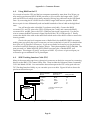
The CPU is the master controller of the CCD camera system. Housed within the CPU
chassis are a flexible power supply, allowing the unit to run off 12 Volts from a wall transformer
or a car battery, a microcontroller, and a frame storage buffer. The microcontroller receives
high level commands from the host computer and translates them into sequences of actions.
For example when the host computer wants to acquire an image it sends the CPU a "take image"
command. The CPU starts by clearing the CCD with the necessary clocking, times the
exposure, and at the end of the exposure clocks the CCD again with a readout sequence, storing
the digitized data in the frame storage buffer. All this happens while the CCD's temperature is
being regulated and communications with the host computer are being maintained.
4.2.
Connecting the Power
The power supply in the CPU is designed to run off 12 Volts AC or DC. Most users will find
using the wall transformer supplied with the systems to be the most convenient way to power
the system. In the field however, battery operation is the most logical choice. In that case you
can simply unscrew the power cable from the wall transformer and attach it to the battery. AC
systems (like the wall transformer) do not have a fixed polarity: swapping the leads at the
transformer does not make a difference as far as the operation of the CPU is concerned since the
output of the transformer is isolated from any other grounds in the system. When powering the
Page 21
Section 4 - Camera Hardware
CPU with a DC supply the polarity of the applied voltage is important, mainly because it is
common in DC systems to connect the negative lead to ground. When powering the CPU from
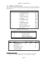
a battery or DC power supply observe the polarities shown in Table 4.1 below for the Power
Connector on the CPU:
Voltage
Power Connection
+12V to +15V
Pin 9
0V or Ground
Pin 4
Table 4.1 - CPU Power Connections
One interesting item about the design of the power supply in the CPU bears mentioning. The
power supply, which is a switching power supply, offers very high efficiency but has an
unusual characteristic. As the input voltage to the power supply drops (due to brownouts or
overall low voltage) the current increases to accommodate the voltage drop. At some point the
CPU will detect that the input voltage has dropped too much and will shut down the TE Cooler
(the largest current drain) in an attempt to not over current the transformer. If this occurs the
host software will tell you about it. If it happens repeatedly you might suspect that the voltage
supply to the wall transformer is low, possibly due to voltage drops in a long extension cord,
etc.
Foreign users of SBIG systems may need to obtain a local version of the wall transformer
as SBIG does not supply them. A trip to your local "Radio Shack" may be necessary to find a
12V, 20VA transformer for the ST-4X and ST-5 or a 12V, 50VA transformer for the ST-6.
4.3.
Connecting to the Computer
The ST-4X, ST-5 and ST-6 CCD Cameras are supplied with a 15 foot cable to connect the system
to the host computer. The connection is between the CPU's COM connector and the Host
Computer's serial COM port. This cable is available in several varieties to support the various
host platforms and we try to query users about their systems to insure they receive the correct
cable. PC based systems have either a 9 or a 25 pin male D type connector at the rear of the
computer for their COM ports. Macintosh computers mostly have a round 8 pin female DIN
connector for their Modem and Printer ports.
For PC systems we recommend using COM 1 or COM 2 for connecting to the camera.
While CCDOPS supports COM 3 and COM 4, often times there are conflicts between these two
COM ports and COM 1 and 2. If the cable we supply you does not have the connector that
mates with your COM ports then a quick trip to Radio Shack for an adapter will solve the
problem. On PC based systems there can also be conflicts between other add-ons and the COM
ports: most commonly Modem cards, Scanner cards, and Mice. If you experience
communications problems with your CCD camera we recommend starting from zero by
removing all possibly conflicting cards from the PC and removing all drivers from your
CONFIG.SYS and AUTOEXEC.BAT files, adding these items back one at a time to find the
source of the conflict. The other common problem that PC users experience in communicating
with the cameras is when running under Windows. Windows can severely limit the speed
CCDOPS uses in communicating with the CCD Cameras and we highly recommend you only
run CCDOPS from DOS when capturing images.
Page 22
Section 4 - Camera Hardware
For Macintosh users we recommend connecting the
camera to the Modem port . The printer port can be used but you
will have to turn off AppleTalk and any Background Printing
Modem
Printer
options you may have enabled.
While the serial cables supplied with the cameras run 15 feet, the length can be extended
to over 1000 feet if done properly. For Macintosh systems this is merely a matter of obtaining or
making a longer cable (refer to the table of COM pinouts in Appendix A). For PC systems the
problem is a bit more involved.
The serial drivers in PC based computers are RS-232 drivers that are not intended to
drive long cables at the high Baud rates used in communicating with the CCD cameras. While
these drivers will typically drive 30 to 50 feet of cable they will rarely drive 100 feet. The
problem is that the RS-232 drivers will not drive the cable capacitance, a problem that is
exacerbated by the requirement to use shielded cable to prevent emissions of radio frequency
interference. What we recommend is a two step approach to tackling the problem.
Try a simple three-conductor shielded cable if your cable run is less than 100 feet. You
may get lucky and be spared the additional expense of a more extensive solution. If you have
problems with your longer cable, and you're sure the problems are related to the length of the
cable (always try our standard cable first to make sure there isn't some other problem) then we
recommend you use a five-conductor shielded cable and an RS-232 to RS-422 converter. RS-422
uses two drivers per signal, driving a pair of wires differentially, and can drive much higher
cable capacitances over longer distances. The CPU has RS-422 drivers so you need only get a
converter for the PC end of the communications link. For specific information about RS-422
converters refer to Appendix A.
4.4.
Connecting the Relay Port to the Telescope
The ST-4X, ST-5 and ST-6 camera systems can be used as autoguiders where the telescope's
position is periodically corrected for minor variations in the RA and DEC drives. The host
software functions as an autoguider in two modes: the Track mode and the Track and
Accumulate mode.
In the Track mode the host software corrects the telescope as often a once every 2
seconds to compensate for drift in the mount and drive system. The host software and the CCD
camera operate in tandem to repeatedly take exposures of the designated guide star, calculate
its position to a tenth of a pixel accuracy and then automatically activate the buttons on the
telescope's hand controller to move the star right back to its intended position. It does this
tirelessly to guide long duration astrophotographs.
In the Track and Accumulate mode the software takes a series of images and
automatically co-registers and co-adds the images to remove the effects of telescope drift.
Typically you would take ten 1 minute "snapshots" to produce an image that is comparable to a
single 10 minute exposure except that no guiding is required. The reason no guiding is
required is that with most modern telescope mounts the drift over the relatively short 1 minute
interval is small enough to preserve round star images, a feat that even the best telescope
mounts will not maintain over the longer ten minute interval. The Track and Accumulate
software does allow correction of the telescope position in the interval between snapshots to
keep the guide star grossly positioned within the field of view, but it is the precise coregistration of images that accounts for the streakless images.
Page 23
Section 4 - Camera Hardware
The host software and the CCD camera control the telescope through the Relay port on
the CPU. By interfacing the CPU to the telescope's hand controller the CPU is able to move the
telescope as you would: by effectively closing one of the four switches that slews the telescope.
Note: You only need to interface the CPU's Relay port to your telescope if you are planning on
using the camera system as an autoguider or feel you need to have the Track and
Accumulate command make telescope corrections between images because your drive has
a large amount of long term drift.
Some recent model telescopes (like the Celestron Ultima and the Meade LX200) have connectors
on the drive controller that interface directly to the CPU Relay port. All that's required is a
simple cable to attach the CPU's 15 pin Relay port to the telescope's telephone-jack type CCD
connector. SBIG offers its TIC (Tracking Interface Cable) for this express purpose although it
would take only one-half hour to modify a standard 6-pin telephone cable to interface to the
Relay port (see Appendix A for specific pin outs, etc.).
Older telescopes generally require modifying the hand controller to accept input from
the CPU's Relay port. The difficulty of this task varies with the drive corrector model and we
maintain a database of instructions for the more popular telescopes that we will gladly share
with you. For a minimal charge will also modify your hand controllers if you feel you do not
have the skills necessary to accomplish such a task.
In general, the Camera has five internal relays that are used in tracking applications.
There is one relay for each of the four correction directions on the hand controller (North, South,
East and West) plus an additional relay for an alarm should the CPU be unable to continue
guiding for some reason. Each of the relays has a Common, a Normally Open, and a Normally
Closed contact. For example, when the relay is inactivated there is a connection between the
Common and the Normally Closed contact. When the relay is activated (trying to correct the
telescope) the contact is between the Common and the Normally Open contacts. These relay
contacts are brought out the CPU's Relay port and the standard cable supplied by SBIG has
twelve colored wires with tinned flying leads (see Appendix A for a pinout of the Relay port
and the standard Relay Cable) that you solder into your hand controller.
If your hand controller is from a relatively recent model telescope it probably has four
buttons that have a "push to make" configuration. By "push to make" we mean that the
switches have two contacts that are shorted together when the button is pressed. If that's the
case then it is a simple matter of soldering the Common and Normally Open leads of the
appropriate relay to the corresponding switch, without having to cut any traces, as shown in
Figure 4.1 below.
A: Unmodified Push to Make Switch
B: Modified Push to Make Switch
c common
relay
switch
switch
nc
no
normally open
Figure 4.1 - Push to Make Switch Modification
Another less common type of switch configuration (although it seems to have been used more
often in older hand controllers) involve hand controller buttons that use both a push to make
Page 24
Section 4 - Camera Hardware
contact in conjunction with a push to break contact. The modification required for these
switches involves cutting traces or wires in the hand controller. Essentially the CPU relay's
Normally Open is wired in parallel with the switch (activating the relay or pushing the hand
controller button closes the Normally Open or Push to Make contact) while at the same time the
Normally Closed contact is wired in series with the switch (activating the relay or pushing the
hand controller button opens the Normally Closed or the Push to Break contact). This type of
switch modification is shown in Figure 4.2 below. One caveat about this type of switch
configuration is that the CPU must be plugged into the hand controller (although the CPU
needn't be powered up) in order for the hand controller to function on its own. This is due to
the necessity of keeping the relay's Normally Closed contact intact since as previously
mentioned the Relay and the Hand Controller switch are in series. This need for the continued
presence of the CPU can be alleviated by making a CPU eliminator as shown in Figure 4.3 to
plug into the end of the relay cable. The CPU eliminator essentially makes the four Normally
Closed contacts.
A: Unmodified Push to Make/Break Switch
B: Modified Push to Make/Break Switch
common
c
common
c
c
switch
nc
no
normally open
normally closed
nc
no
nc
relay
no
normally open
normally closed
Figure 4.2- Push to Make/Brake Modification
15 Pin Male D Connector
(back view)
1
8
15
9
Figure 4.3 - CPU Eliminator Plug
The last type of hand controller that is moderately common is the resistor joystick. In this
joystick each axis of the joystick is connected to a potentiometer or variable resistor. Moving the
joystick handle left or right rotates a potentiometer, varying the resistance between a central
"wiper" contact and the two ends of a fixed resistor. The relays in the CPU can be interfaced to
the joystick as shown in Figure 4.4 below. Essentially the relays are used to connect the wire
that used to attach to the wiper to either end of the potentiometer when the opposing relays are
activated.
Page 25
Section 4 - Camera Hardware
A
+ relay
- relay
c
A
c
wiper
B
nc
C
B
potentiometer
nc
no
no
C
A: Unmodified Joystick
B: Modified Joystick
Figure 4.4 - Joystick Modification
A slight variation on the joystick modification is to build a complete joystick eliminator as
shown in Figure 4.5 below. The only difference between this and the previous modification is
that two fixed resistors per axis are used to simulate the potentiometer at its mid position. You
do not need to make modifications to the joystick; you essentially build an unadjustable version.
This may be easier than modifying your hand controller if you can trace out the wiring of your
joystick to its connector.
A
- relay
+ relay
c
c
A
no
wiper
B
nc
nc
no
C
B
R
potentiometer
C
R/2
A: Unmodified Joystick
R/2
B: Joystick Eliminator
Figure 4.5- Joystick Eliminator
4.5.
Modular Family of CCD Cameras
With the introduction of the ST-6 CCD Camera in 1992 SBIG started a line of high quality, low
noise, modular CCD cameras. This line is being expanded by the introduction of the ST-4X and
ST-5. All three of these cameras share a common CPU referred to as the Universal CPU. A
single CPU can support the three different cameras through the use of an integrated Optical
Head and Readout/Clocking Electronics in the case of the ST-6 or with the separate Optical
Head and Readout/Clocking Electronics in the case of the ST-4X and ST-5.
The benefits of a modular line of CCD Cameras are many fold. Users can buy as much
CCD Camera as they need or can afford, with the assurance that they can upgrade to higher
performance systems in the future. With a single CPU supporting all three systems, camera
control software like CCDOPS can easily support all three models. This last point assures a
wide variety of third party software. Software developers can produce one package for the
many users across the model line instead of three different packages for each of the cameras.
Page 26
Section 4 - Camera Hardware
While the ST-4X, ST-5 and ST-6 have many similarities, there are also important
differences between the products. Table 4.2 below highlights the differences from a system's
standpoint:
Camera
ST-4X
ST-5
A/D
Resolution
14 bits
14 bits
Temperature
Regulation
Open Loop
Closed Loop
Electromechanical
Vane
No
No
ST-6
16 bits
Closed Loop
Yes
Electronic
Shutter
None
1
1000 second
1
300
second
Table 4.2 - System Features
How these features affect the average user are discussed in the paragraphs below:
A/D Resolution - This is a rough indication of the camera's dynamic range. Higher precision
A/D Converters are able to more finely resolve differences in light levels, or for
larger CCDs with greater full well capacities, they are able to handle larger total
charges with the same resolution.
Temperature Regulation - In an open loop system like the ST-4X the CCD cooling is either
turned on or turned off. While this provides for adequate cooling of the CCD,
the CCD's temperature is not regulated which makes it important to take dark
frames in close proximity to the associated light frame. Closed loop systems like
the ST-5 and ST-6 regulate the CCD's temperature to an accuracy of ±0.1° C
making using a library of dark frames practical.
Electromechanical Vane - Having the vane in the ST-6 means the host software can effectively
"cover the telescope" and take dark frames remotely, without the user having to
get up and physically cover the telescope.
Electronic Shutter - Having an electronic shutter involves having a CCD with a frame transfer
region. These CCDs actually have an array that has twice the number of rows
advertised, where the bottom half is open to the light (referred to as the Image
Area), and the top half is covered with a metalization layer (referred to as the
Storage Area). In frame transfer CCDs at the end of the exposure, the pixel data
from the Image Area is transferred into the Storage Area very rapidly where it
can be read out with a minimum of streaking.
In addition to the system level differences between the ST-4X, ST-5 and ST-6, Table 4.3 below
highlights the differences owing to the different CCDs used in the cameras:
Camera
ST-4X
ST-5
ST-6
CCD
Used
TC-211
TC-255
TC-241
Number
of Pixels
192 x 164
320 x 240
375 x 242
Pixel
Dims.
13.75 x 16µ
10 x 10µ
23 x 27µ
Array
Dimension
2.6 x 2.6mm
3.2 x 2.4mm
6.6 x 8.8mm
Read
Noise
22e- rms
20e- rms
30e- rms
Full Well
Capacity
150Ke50Ke400Ke-
Table 4.3- CCD Differences
How these various specifications affect the average user is described in the following
paragraphs:
Number of Pixels - The number of pixels in the CCD affects the resolution of the final images.
The highest resolution device is best but it does not come without cost. Larger
CCDs cost more money and drive the system costs up. They are harder to cool,
Page 27
Section 4 - Camera Hardware
require more memory to store images, take longer to readout, etc. With PCs and
Macintosh computers offering graphics resolutions of 320 x 200 to 640 x 480 with
good grey scale, the CCDs used in the ST-4X, ST-5 and ST-6 offer a good trade off
between cost and resolution, matching the computer's capabilities well.
Pixel Dimensions - The size of the individual pixels themselves really plays into the user's
selection of the system focal length. Smaller pixels and smaller CCDs require
shorter focal length telescopes to give the same field of view that larger CCDs
have with longer focal length telescopes. Smaller pixels can give images with
higher spatial resolution up to a point. When the pixel dimensions (in
arcseconds of field of view) get smaller than roughly half the seeing, decreasing
the pixel size is essentially throwing away resolution. Another aspect of small
pixels is that they have smaller full well capacities.
For your reference, if you want to determine the field of view for a pixel
or entire CCD sensor you can use the following formula:
Field of view (arcseconds) =
8120 x size (mm)
focal length (inches)
where size is the pixel dimension or CCD dimension in millimeters and the focal
length is the focal length of the telescope or lens in inches. Also remember that
1° = 3600 arcseconds.
Read Noise - The readout noise of a CCD camera affects the graininess of short exposure
images. For example, a CCD camera with a readout noise of 30 electrons will
give images of objects producing 100 photoelectrons (very dim!) with a Signal to
Noise (S/N) of approximately 3 whereas a perfect camera with no readout noise
would give a Signal to Noise of 10. Again, this is only important for short
exposures or extremely dim objects. As the exposure is increased you rapidly get
into a region where the signal to noise of the final image is due solely to the
exposure interval. In the previous example increasing the exposure to 1000
photoelectrons results in a S/N of roughly 20 on the camera with 30 electrons
readout noise and a S/N of 30 on the noiseless camera. It is also important to
note that with the SBIG CCD cameras the noise due to the sky background will
exceed the readout noise in 15 to 60 seconds on the typical amateur telescopes.
Even the $30,000 priced CCD cameras with 10 electrons of readout noise will not
produce a better image after a minute of exposure!
Full Well Capacity - The full well capacity of the CCD is the number of electrons each pixel can
hold before it starts to loose charge or bleed into adjacent pixels. Larger pixels
hold more electrons. This gives an indication of the dynamic range the camera is
capable of when compared to the readout noise, but for most astronomers this
figure of merit is not all that important. You will rarely takes images that fill the
pixels to the maximum level except for stars in the field of view. Low level
nebulosity will almost always be well below saturation. While integrating longer
would cause more build up of charge, the signal to noise of images like these is
proportional to the square-root of the total number of electrons. To get twice the
signal to noise you would have to increase the exposure 4 times. An ST-5 with
its relatively low full well capacity of 50,000e- could produce an image with a
S/N in excess of 200!
Antiblooming - All the SBIG CCD cameras have antiblooming protection. Blooming is a
phenomena that occurs when pixels fill up. As charge continues to be generated
in a full pixel, it has to go somewhere. In CCDs without antiblooming protection
the charge spills into neighboring pixels, causing bright streaks in the image.
Page 28
Section 4 - Camera Hardware
With the CCDs used in the SBIG cameras the excess charge can be drained off
saturated pixels by applying clocking to the CCD during integration. This
protection allows overexposures of 100-fold without blooming.
From the telescope's point of view, the different models offer differing fields of view for a given
focal length, or turned around, to achieve the same field of view the different models require
differing focal lengths. Tables 4.4 and 4.5 below compare the fields of view for the cameras at
several focal lengths, and vice and versa.
Camera
ST-4X
ST-5
ST-6
C8, 8" f/10
LX200, 10" f/35
Field of
Pixel
Field of
Pixel
View
Size
View
Size
(arcmins)
(arcsecs) (arcmins)
(arcsecs)
4.2x4.2
1.3x1.5
11.7x11.7
3.7x4.3
5.4x4.1
1.0x1.0
14.4x10.8
2.7x2.7
14.6x11.1
2.3x2.7
38.9x29.5
6.2x7.3
Table 4.4 - Field of View
14" f/11
Field of
Pixel
View
Size
(arcmins)
(arcsecs)
2.3x2.3
0.7x0.8
2.8x2.1
0.5x0.5
7.6x5.7
1.2x1.4
Focal Length to fill
ST-4X/ST-5
Focal Length to fill
ST-6
0.5°
275mm =
11 inches
760mm =
30 inches
Jupiter
40 arcseconds
13000mm =
510 inches
34000mm =
1350 inches
M51-Whirlpool
Galaxy
8x5
arcminutes
1040mm =
41 inches
3700mm =
145 inches
M27-Dumbell
Nebula
8.5 x 5.5
arcminutes
M57-Ring Nebula
1.3 x 1
6400mm =
arcminutes
250 inches
Table 4.5 - Focal Length Required
Object
Size
Moon
"
"
23000mm =
900 inches
From these numbers you can deduce that the popular C8, an 8" f/10 telescope will nicely frame
the ST-6 for many popular objects whereas a much shorter system (f/3, perhaps achieved with a
focal reducer) will frame the same objects for an ST-4X or ST-5. Another point to bear in mind is
that, except for planetary images, you'll rarely take images where the pixel size in seconds of arc
is down near the seeing limit. Most objects are relatively large, where the field of view is more
important than whether the individual pixels are less than half the seeing.
5
f/6.3 with the Meade star digonal focal reducer.
Page 29
Section 5 - Camera Software Reference
5.
Camera Software Reference
This section contains detailed information about CCDOPS, the host computer software for the
ST-4X, ST-5 and ST-6 CCD Cameras. While section 5.1 contains information of a general nature,
section 5.2 is a very detailed explanation of every command available in CCDOPS, and is
organized more as a software reference rather than a narrative to be read from top to bottom.
5.1.
Different Host Computers
Santa Barbara Instrument Group offers CCDOPS for both IBM PCs/Compatibles and
Macintosh computers. The CCDOPS software package supports all three cameras and is
designed to be 95% operationally identical on the two different platforms. Images captured on
the IBM PC can be used on the Macintosh and vice versa (see Appendix D for more information
on Cross Platform Compatibility). The differences between the PC and Macintosh versions of
the software are very minor, mostly owing to minor differences in hardware capabilities
between the two platforms. Both environments are menu based with full support for the
mouse.
5.1.1. Installing the Software
The CCDOPS software is provided on floppy diskette, and should be copied to your system's
hard disk prior to use. Copy all the files to a directory or folder on your hard disk by following
the instructions below:
IBM PC Users
1
2
1. Insert the 3 or 5
1
inch diskette into the floppy disk drive.
4
2. At the MS-DOS prompt type "CD \" then hit the Enter key to log into the root
directory of your hard disk.
3. Type "MKDIR CCDOPS" then hit the Enter key to create a directory for the software.
4. Type "CD CCDOPS" then hit the Enter key to make that directory active.
5. Type "COPY A:*.*" or "COPY B:*.*" depending on which floppy drive you are using
then hit Enter to copy all the software to the CCDOPS directory on your hard disk.
When you want to run the software, turn on your computer and type in the following
sequence of commands at the MS-DOS prompt:
CD \CCDOPS
CCDOPS
Note: We strongly advise that you do not take images from within Windows or else your ability
to communicate with the camera at high speeds may be severely limited.
Macintosh Users
1
2
1. Insert the 3 inch diskette into the floppy disk drive.
2. Create a new folder on your hard disk named CCDOPS.
3. Click and drag all the files on the CCDOPS diskette into the folder you've just created.
After you have finished installing the software place the floppy disk in a safe place in case you
need to reinstall it later.
Page 31
Section 5 - Camera Software Reference
5.1.2. The CCDOPS User Interface
The CCDOPS environment presents the user with a user-friendly menu based interface. Rather
than having to remember long command names and do a lot of typing, CCDOPS presents all
the commands in a logically organized menu structure. The software has been designed to be
simple for inexperienced users while offering advanced capabilities as experience grows. As
previously stated, many man-hours and much improvement from user's comments and
suggestions have gone into the development of CCDOPS. We encourage users to continue to
help us improve the software through your comments.
At the top of the screen is a menu bar with pull-down menus of logically grouped
commands. For example the Camera Menu has commands that allow you to take an image (the
Grab Command), focus the camera (the Focus Command) or try to initiate communications
with the CCD Camera (the Establish COM Link command). The PC and Macintosh menu bars
are shown with one of the pull-down menus in Figure 5.1 below:
*
File
Camera
Display
Open...
Save...
Save Track List...
Delete
Utility
Alt-O
Alt-S
Misc
Track
FiLter
PC Menu Bar
Create Directory...
Set Path/Filter...
EXit
File Edit
Alt-X
Camera
Display Utility Misc Track Filter
Grab...
Focus...
G
F
Macintosh Menu Bar
Setup...
Auto Offset Adjust
Manual Offset Adjust
Establish COM Link
Upload Dark Frame...
Figure 5.1 - CCDOPS Menu Bar
Some of the menu commands operate immediately like the Establish COM Link command in
the Camera menu. Other commands require further user input such as the Grab command.
These "further input required" commands are shown with an ellipsis (...) after the command
name. Also, some often used commands have a "hot-key" associated with them which is shown
in the menu. Typing the hot-key combination invokes the command. For example holding
down the key on the Macintosh or the Alt key on the PC and then hitting the G key invokes
the Grab Command.
Page 32
Section 5 - Camera Software Reference
At the bottom of the screen is the Status Window. The Status Window, shown in Figure
5.2 below, contains two or three sections. The top section called the Status Box is used by the
software to provide written feedback to the user about the activities being performed.
On the PC version of CCDOPS, there is a double-outlined Data Buffer Box below the
Status Box that tells the user about the status of image data held in the software's image buffer.
The type of camera used to take the image and the name of the image are shown as well as an
indication of whether the image has been saved on the disk drive. Also shown is the status of
the Color Tables indicating whether any custom color tables have been loaded. Color Tables are
used in conjunction with the Display Command to assign different colors to the display of
images rather than the typical grey scale.
Status
Taking light exposure...
Grab complete.
Data Buffer
Name:No data present
Camera
Link:[ST-5]COM1:115K
Res:High
Saved:-
Color Tables:----
Setpoint:-20.00Temperature:-19.75 ( 75%)
Reuse Darks:No
Filter:Red
PC Status Window
Macintosh Status Window
Figure 5.2- Status Window
At the very bottom of the Status Window is the double outlined Camera Box that indicates the
status of any CCD camera attached to the host computer through one of its COM ports. The
Link status shows the type of camera and the COM port and Baud Rate used to communicate
with the camera. Also shown (if a camera is attached) is the status of the camera's cooling. For
ST-4X cameras the cooling is either turned on and Enabled or is Off. For ST-5 and ST-6 cameras
the user selectable setpoint temperature and the camera's actual temperature are shown as well
as the percentage of power being applied to the TE cooler to maintain that setpoint.
The second line of the Camera Box shows the resolution mode the camera is setup for
(using the Camera Setup command) and whether dark frames will be reused. In the lower right
hand corner the active optical filter from the filter wheel is shown. 6
The region between the menu bar and the status window is called the Desktop. The
CCDOPS software uses the Desktop area to get further user input for commands like the Grab
Command using data entry boxes called Dialogs (or Dialog Boxes). The Desktop area is also to
inform the user about the progress of activities that take a long time, such as taking a 1 minute
exposure, and to warn the user about important aspects regarding the operation of the camera.
6
CCDOPS supports the motorized and manual CFW6 filter wheels. Commands in the Filter menu are
used to position the motorized filter wheel or inform the software about the position of the manual
filter wheel.
Page 33
Section 5 - Camera Software Reference
Dialog Boxes pop-up on the Desktop and present the user with a series of data entry
items, which as stated previously, fine tune the operation of certain commands. Within these
dialogs, data entry items are arranged in a vertical fashion. The user proceeds through each
item, setting it as appropriate. Figure 5.3 below shows the PC and Macintosh versions of the
dialog box for the Grab Command:
Grab
Exposure time (0.01-3600):
Dark Frame:
Auto display:
Auto contrast:
Background (0-65535):
Range (16-65536):
Exposure delay(0-99):
Auto Grab:
30.00
None Also
Yes No
Yes No
0
1000
0
Yes No
[ Enter ]
[
Only
Esc
]
PC Grab Dialog
Macintosh Grab Dialog
Figure 5.3 - Grab Dialog
The Grab Dialog is a good example because it shows the two major types of items commonly
found in dialog boxes: list items and data entry items. List items are like the Dark Frame item
shown above where the user selects one setting from a list of settings. Data entry items like the
Exposure time require the user to type in a value.
5.1.3. CCDOPS for IBM PCs
The PC version of CCDOPS runs under DOS but provides a very user friendly environment.
Even though it is not Windows software, the user interface is menu based and supports a broad
range of hardware configurations. Running under DOS assures the maximum compatibility
with the PC systems users currently have and operate.
In the PC environment the CCDOPS software works in two modes: Command Mode
and Graphics Mode. The command mode is used to interact with the user and to control the
Page 34
Section 5 - Camera Software Reference
acquisition and processing of images. The Graphics Mode (discussed further below) is used
when image display is required.
Command Mode
Along the top of the Command Mode screen is a menu bar with its pull-down menus (shown in
the top of Figure 5.1). Pulling down menus and executing commands can be done using the
keyboard or the mouse. Using the mouse is quite easy: you simply click the mouse button on
the menu title to pull down the menu and then click the mouse again on the desired menu
command. Using the keyboard is almost as intuitive: you simply select the menu by using the
left and right arrow keys, and then select the menu command using the up and down arrow
keys, executing the command by hitting the Enter key once the appropriate command has been
selected.
You also perform data entry in Dialog Boxes using the keyboard and the mouse. Using
the keyboard you select the item to change using the up and down arrow keys and then
changed the item by typing in the desired value or by using the left and right arrow keys for list
items. You can also use the Tab key to tab down through the items in a dialog or you can click
the mouse on an item to move to that item or click in one of the options in a list item to select
that option.
At the bottom of all dialog boxes are two buttons: Enter and Esc. Clicking the mouse on
the Enter button or hitting the Enter key causes the command to read all the data entry back
from the dialog and finish executing the command. Clicking the Esc button or hitting the Esc
key aborts the command.
Advanced Tips
•
Each item in a dialog can be accessed though hot-keys. By holding down the Alt
key while hitting the key shown in red or highlighted you can move directly to
that item. For example hitting Alt E moves to the Exposure time item in the Grab
Dialog shown above.
•
In list items options can be selected by hitting the first letter of the option. For
example, hitting Y will select the Yes option if you are in the Auto display item of
the Grab Dialog.
•
In data entry items the first key hit erases the entire contents of the data entry
item unless you hit the Backspace key or the left or right arrow keys described
below.
•
In data entry items the Backspace key erases one character and the left and right
arrow keys move the cursor within the data entry allowing correction or
insertion.
•
In the data entry items hitting the Delete or Del keys erase the entire contents of
the data entry item.
Graphics Mode
In the PC version of CCDOPS the software switches to Graphics Mode when the image needs to
be displayed. Graphics mode is used for the Display Command in the Image Menu as well as
the Focus and Track and Accumulate modes. These modes all display the image in the upperright corner of the display with an optional pull-down menu in the upper-left corner of the
display.
Page 35
Section 5 - Camera Software Reference
The size of the image and the "quality" of the image depends largely on the type of
graphics adapter you have in your computer. VGA and/or Super VGA7 are highly
recommended in all cases except where you have dual systems: one portable system that you
take into the field to acquire images which can have less than VGA capabilities and a second
system for display and image processing. With VGA displays the images can be shown using
64 shades of grey. This produces very nice looking images.
EGA based systems are also supported. With an EGA color display the images are "ok"
but do not offer much latitude in terms of grey scales or brightness variations. An EGA display
adapter with a monochrome monitor works fairly well, again supporting 64 shades of grey but
it's not nearly as flexible as VGA based systems.
At the very bottom of the ladder are systems based upon CGA graphics. These systems
have very poor spatial and color resolution and produce "blocky" looking images. Our
intention in supporting CGA systems was to allow older laptop computers to be used in the
field for acquisition of images. Users will not be happy with the quality of displayed images for
any serious image processing and are strongly encouraged to upgrade to VGA based systems.
In Graphics Mode data entry is minimal, restricted mainly to selecting items from pulldown menus. As previously mentioned, many of the graphics mode displays have a pull-down
menu. The menu is indicated by the presence of a menu name in a rectangular box in the
upper-left corner of the display as shown in Figure 5.4 below. Accessing items in the menu is
easily achieved using the mouse or the keyboard.
Display
X-Hairs
H-Flip
V-Flip
Zoom
Crop
Smoothing
Negative
Quit
Figure 5.4 - Graphics Mode Menu
Using the mouse is identical to that in the Command Mode: you click on the menu title to reveal
the pull-down menu and then click again on the command you wish to execute. Using the
keyboard is also similar to Command Mode: you hit the Enter or Down Arrow keys to pulldown the menu, select the appropriate item using the up and down arrow keys, and then hit
the Enter key again to execute the command. The items also have "hot-keys" associated with
them that will make it quicker as you gain experience with the software. Hitting the first letter
of the command name will execute the command without having to pull down the menu. As
an example, hitting the "X" key would execute the "X-Hairs" command in the menu shown
above.
7
CCDOPS for the PC supports VESA compliant and Paradise and Tseng 4000 based Super VGA cards
where images are displayed in the 640x480 or 640x400 pixel modes with 256 colors.
Page 36
Section 5 - Camera Software Reference
Note: You do not have to hold down the Alt key to access the hot-keys in the Graphics Mode.
When you are through with the command you are using that invoked the Graphics Mode hit
the Esc key to return CCDOPS to the Command Mode.
5.1.4. CCDOPS on Macintosh Computers
The Macintosh version of CCDOPS takes full advantage of the graphical user interface (GUI)
built into the Macintosh System Software. This is the ideal environment for imaging
applications like CCDOPS since the software has simultaneous access to menus and dialogs for
controlling the camera as well as high level graphics for displaying the images.
Any Macintosh user also has the benefit of Apple's enormous investment in the area of
user interfaces. Software packages for the Macintosh share the common "toolbox" which makes
learning to operate the Macintosh a one-time event. All software packages share the same look
and feel. If you know how to use MacWrite you're right at home with other packages,
including CCDOPS. Any Macintosh user will freely admit that he or she "hardly ever reads the
manual".
While the PC and Macintosh versions of CCDOPS provide virtually the same level of
capabilities there are minor differences between the two programs owing largely to differences
in the operating system. Where as the PC CCDOPS must switch between Command Mode and
Graphics Mode, CCDOPS for the Macintosh offers both capabilities simultaneously. CCDOPS
for the Macintosh also takes advantage of the "complete system" approach that the Macintosh
offers allowing customization of color tables, printing of images and cutting and pasting.
If you are a new user to the Macintosh and CCDOPS is your first program we ask you to
spend the time with the training disks that Apple has provided you in learning to use the
system. It is a small investment in time that will pay off for years.
5.2.
CCDOPS Menus and Commands
This section has detailed descriptions about the Menus and their respective Commands. For
each Menu, a brief description of each Command is given. For Commands that require a lot of
user input or explanation, a separate description is included.
5.2.1. Command Tree
The following figure is a Command Tree of each of the Menus and Commands available in
CCDOPS.
Page 37
Section 5 - Camera Software Reference
Page 38
Section 5 - Camera Software Reference
5.2.2. File Menu on the Macintosh
Purpose:The commands in the File menu allow loading and saving images on disk.
Commands
Open
Close
Save
Save As
Revert to Saved
Page Setup
Print
This command loads ST-4X, ST-5 or ST-6 image files from disk into
memory where they can be displayed or processed.
Closes the image in memory by purging it from memory. If the
image has changed and has not been saved you are given the
opportunity to save it before closing it. Note that you must close
one image before you can open another.
Saves the image held in memory on the disk. The same name used
to load the file or last save it is used. You also use this command to
save Track Lists produced by the Track and Accumulate command
by activating the Track List window and invoking this command.
Saves the image held in memory on the disk, giving you the
opportunity to rename the image or save it in the folder of your
choice. You can also choose to save the image using the
Compressed, Uncompressed, FITS or TIFF formats.
Discards any changes made to the image in memory since the last
save by reloading the image from disk.
Allows you to select the orientation and other page
setup options when printing images. We suggest using
the Portrait orientation and turning off the Graphics
Smoothing and Faster Bitmap Printing options.
Prints the image as it is displayed in the Picture window. If your
printer does not support grey-scale you should first set the
Graphics mode item in the Mac Setup command to one of the two
color modes.
Quits CCDOPS back to the Finder.
Quit
Notes
• The Compressed and Uncompressed image formats are SBIG native formats. You can
typically use 30% to 50% less disk space by using the Compressed format.
• The TIFF format is supported by third party graphics processing programs and allows you
to export CCD images to those other programs.
• The FITS format is supported by third party astronomical image processing programs and
allows you to export CCD images to those programs.
• In addition to printing images, you can make a copy of the image displayed in the Picture
window by making that window active and then using the Copy command in the Edit
menu.
• When printing grey scale images remember to select the Color/Greyscale Print option in
the Print dialog.
See Also: Mac Setup Command, Save FITS Command, Save TIFF Command
Page 39
Section 5 - Camera Software Reference
5.2.3. File Menu on the PC
Purpose:The commands in the File menu allow loading and saving images on disk.
Commands
Open
Save
Save Track List
Delete
Create Directory
Set Path/Filter
Exit
This command loads ST-4X, ST-5 or ST-6 image files from disk into
memory where they can be displayed or processed.
This command saves the image in memory onto the disk. You are
asked for the name to use in saving the file, and if that name would
overwrite an existing image you are warned. You can save the
image using the Compressed, Uncompressed, FITS or TIFF
formats.
Use this command to save the Track List produced by the Track
and Accumulate command if you plan on flat fielding your images.
This command allows you to delete files on the disk to free up
space without having to exit to DOS. The files that match the Filter
in the Path from the Set Path/Filter Command are shown.
This command allows you to create a new directory in which to
store images without having to exit to DOS. You enter the path
and name of the directory to create and you can also make the
newly created directory the current Path.
This command allows you to set the Path where CCDOPS looks for
image files to load and save and the Filter which allows only files
matching the filter to be shown in the Load Image command.
This command quits CCDOPS back to DOS. If there is unsaved
image data or the camera's temperature regulation is active you are
given the chance to not exit.
Notes
• The Compressed and Uncompressed image formats are SBIG native formats. You can
typically use 30% to 50% less disk space by using the Compressed format.
• The TIFF format is supported by third party graphics processing programs and allows you
to export CCD images to those other programs.
• The FITS format is supported by third party astronomical image processing programs and
allows you to export CCD images to those programs.
• In the Open and Delete commands, clicking on the [ Info? ] button or hitting the Space bar
shows the Image Parameters associated with the currently highlighted file.
• The Path is the drive and directory where CCDOPS tries to open and save images. For
example setting the Path to "C:\ST-6\DEEPSKY" (without the quotes) causes CCDOPS to
look in the DEEPSKY subdirectory of the ST-6 directory on hard drive C:. To set the Path to
the directory where CCDOPS resides erase the Path or set it to ".\" (do not type the quotes).
• The Filter is used by the Open and Delete commands to select files to show in the directory
listing. Only files matching the Filter are shown. For example, setting the Filter to "*.ST6"
shows all files with the ST6 extension. To show all files set the Filter to "*.*" (once again, do
not type the quotes).
• If more than 40 files are available in the Open and Delete commands then you can use the
PgDn and PgUp keys to see 40 files at a time.
See Also: Save FITS Command, Save TIFF Command
Page 40
Section 5 - Camera Software Reference
Save FITS Command
File Menu, Save Command
Purpose:
The Save FITS Command is used to save the image in memory on disk using the FITS format.
You access this command through the Save command by selecting FITS format.
Dialog Parameters
Bits per pixel Set this item according to the precision required in the FITS file. For 16 bit
FITS files the 16 bit image data is saved unchanged. For 8 bit FITS files the
16 bit image is scaled using the Back and Range parameters.
Back/Range For 8 bit FITS files these parameters control the scaling of the 16 bit image
data to the 8 bit FITS file data. Pixels below the Back value are written as
zero. Pixels above Back + Range are written as 255. Pixels between Back
and Back + Range are scaled linearly from 0 to 255.
Object Set this item to any text you want to attach to the FITS file describing the
object imaged.
Date of Obs. This item gets set to the date the FITS file is being saved and can be
changed.
Institution Set this item to any text you want to attach to the FITS file describing the
institution that imaged the object.
Telescope Set this item to any text you want to attach to the FITS file describing the
telescope that imaged the object.
Observer Set this item to any text you want to attach to the FITS file describing the
observer that imaged the object. This data is initialized from the Telescope
Setup command.
Comment Set this item to any text you want to attach to the FITS file as a comment.
This is initialized to the Note attached to the image with the Edit
Parameters command, but can be overridden.
Notes
• Only 8 bit FITS files use the Back and Range parameters to scale the image data. 16 bit FITS
files are written directly from the image pixel values.
• Prior to saving 8 bit FITS files you may wish to display the image to find the appropriate
settings for the Back and Range parameters. As a convenience the settings from the
Display Image command are automatically copied to the Back and Range parameters in
this command, but they can be overridden, of course.
See Also: Display Image Command, Edit Parameters Command
Page 41
Section 5 - Camera Software Reference
Save TIFF Command
File Menu, Save Command
Purpose:
The Save TIFF Command is used to save the image in memory on disk using the TIFF format.
You access this command through the Save command by selecting TIFF format.
Dialog Parameters
Bits per pixel Set this item according to the precision required in the TIFF file. For 16 bit
TIFF files the 16 bit image data is saved unchanged. For 8 bit TIFF files the
16 bit image is scaled using the Back and Range parameters.
Back/Range For 8 bit TIFF files these parameters control the scaling of the 16 bit image
data to the 8 bit TIFF file data. Pixels below the Back value are written as
zero. Pixels above Back + Range are written as 255. Pixels between Back
and Back + Range are scaled linearly from 0 to 255.
Strips You will typically want to set this item to Multiple as most TIFF readers are
capable of reading that format. The Single setting can be used if your TIFF
reader will not read TIFF files created with the Multiple setting.
Observer Set this item to any text you want to attach to the TIFF file describing the
observer that imaged the object. This data is initialized from the Telescope
Setup command.
Comment Set this item to any text you want to attach to the TIFF file as a comment.
This is initialized to the Note attached to the image with the Edit
Parameters command, but can be overridden.
Notes
• Only 8 bit TIFF files use the Back and Range parameters to scale the image data. 16 bit TIFF
files are written directly from the image pixel values.
• Prior to saving 8 bit TIFF files you may wish to display the image to find the appropriate
settings for the Back and Range parameters. As a convenience the settings from the
Display Image command are automatically copied to the Back and Range parameters in
this command.
See Also: Display Image Command, Edit Parameters Command.
Page 42
Section 5 - Camera Software Reference
5.2.4. Edit Menu on the Macintosh
Purpose:The commands in the Edit menu are the standard edit commands for the Macintosh plus an
additional command for the Icon Bar.
Commands
Undo
Cut
Copy
This command is used with desk accessories.
This command is used with desk accessories.
This command is used with desk accessories or when the Picture
Window is active to make a copy of the image displayed onto the
Clipboard where it can be pasted into the Scrapbook or other
application.
This command is used with desk accessories.
This command makes the Icon Bar visible or invisible.
Paste
Show/Hide Icon Bar
Notes
• The Icon Bar is a small window with icons in it for Grab, Focus, Track, Track and
Accumulate, Save and Open. Clicking on one of these icons is a shortcut for the pulling
down the menu and invoking the respective commands.
Page 43
Section 5 - Camera Software Reference
5.2.5. Camera Menu
Purpose:
The commands in the Camera menu are used to control the camera for taking images,
focusing, etc.
Commands
Grab
Focus
Setup
Auto Offset Adjust
(ST-6 Only)
Manual Offset Adjust
Establish COM Link
Upload Dark Frame
This command is used to take a single image or a sequence of
images and log them to disk (Auto Grab Command). Typically
you would use this command once the object is focused and
centered in the field of view and you're ready to take the "keeper"
image.
This command is used to focus the CCD camera or to center objects
in the field of view as it repeatedly takes images and displays them.
This command is used to configure the CCD camera hardware for
subsequent images. Items include the temperature regulation,
resolution, etc.
For ST-6 cameras this command automatically adjusts the head
offset by closing the vane and measuring the video black level,
adjusting the offset until the black level is between 2,000 and 10,000
counts.
For ST-6 cameras this command allows the user to manually adjust
the head offset. For the ST-4X and ST-5 the head offset is not
adjustable although this command can be used to measure the
black level. If you choose to use this command you should adjust
the ST-6's offset using the cursor keys until the Video reads
between 2,000 and 10,000 counts.
This command tries to establish a communications link with an
ST-4X, ST-5 or ST-6 attached to the serial COM port. The desired
COM port and Baud rate are set using the Mac Setup or PC Setup
commands in the Misc menu. Once a communications link is
established, the Status Window is updated to show the active COM
port and Baud rate.
This command allows you to select a previously taken and saved
dark image and upload it to the camera. That dark frame can be
reused in subsequent images if the Reuse Dark Frames item in the
Camera Setup command is enabled.
Notes
• For a dark frame to be reusable it must match the current imaging mode parameters
including the resolution, frame size, exposure duration, temperature, etc.
See Also: Grab Command, Auto Grab Command, Focus Command, Camera Setup
Commands, Mac Setup Command, PC Setup Command
Page 44
Section 5 - Camera Software Reference
Grab Command
Camera Menu
Purpose:
The Grab Command is used to take a single exposure or a series of exposures and log them to
the disk (Auto Grab Command).
Dialog Parameters
Exposure time Set this item to the desired exposure duration in increments of a hundredth
of a second.
Dark frame Set this item to Only to take and download a single dark frame. Set the item
to Also to take a dark frame followed by a light frame and download the
difference. Set this item to None to take and download a single light frame.
Image size Set this item to Full to take an image using the CCD's full field of view.
The Half and Quarter settings take an image using the central
Auto display
(PC Only)
Auto contrast
(PC Only)
Background
Range
(PC Only)
Exposure delay
Auto Grab
1 1
1 1
x or x
2 2
4 4
field of view, reducing the memory requirements accordingly. On the ST4X the Half setting takes a Half Frame image where the lower half of the
CCD, at full width, is used to reduce streaking.
The image is automatically displayed after being downloaded if this
item is set to Yes.
Note: On the Macintosh the image is always displayed after being downloaded.
When the Auto Display item is set to Yes , setting this item to Yes causes
the image to be displayed using Auto Contrast.
Note: On the Macintosh Auto Contrast is used if the Auto check-box is selected in
the Contrast Window.
These items affect the contrast of the displayed image if the Auto
Display item is set Yes and the Auto Contrast item is set No.
Note: On the Macintosh the Back and Range parameters from the Contrast
Window are used.
Setting this item to any value except zero causes the software to delay that
number of seconds before taking the light image. This allows the user to
start guiding or turn off the lights, for example.
Setting this item to Yes invokes the Auto Grab command which allows
taking a sequence of images and logging them to disk at a regular interval.
Notes
• When taking a dark frame with the ST-4X and ST-5 the user is asked to cover the telescope.
• If the Camera Setup has the Reuse Dark Frames item set Yes the Grab Command will try to
reuse any dark frames stored in the Camera. This can increase throughput significantly if
you plan on taking several images with the same exposure time.
• If you get serial "Time Out" errors while the image is being downloaded you should
decrease the Baud rate one step using the PC or Mac Setup command.
• Hit the Esc key on the PC or hit -Period on the Macintosh to abort an image in progress.
See Also: Auto Grab Command, Display Image Command, Camera Setup Commands, PC
Setup Command, Mac Setup Command, Macintosh Contrast Window
Page 45
Section 5 - Camera Software Reference
Auto Grab Command
Camera Menu, Grab Command
Purpose:
The Auto Grab Command is used to take a sequence of images at a periodic interval and log
them to disk.
Dialog Parameters
File name Set this item to the name you want the Auto Grab command to use when
saving the files. For Macintosh users you enter the name and select the
destination folder using the Standard File Save dialog. For PC users you
can enter up to 5 characters for the file name plus a three character
extension, for example ORION.FTS. In both cases the Auto Grab command
appends "NNN" to the file name as the images are saved where NNN is the
image sequence number from 001 to 999 . In the example above the names
would be ORION001.FTS, ORION002.FTS, etc.
Type Set this item to the type of file you want saved for each image. The
Uncompressed and Compressed formats are SBIG native formats which
can be read back in and processed by CCDOPS. The TIFF and FITS formats
are supported by other software packages but you will not be to load
images saved in these formats back into CCDOPS.
No. of Exp. Set this item to the number of images you wish to grab and log to disk.
Exp. interval Set this item to the interval from start of image to start of image. For
example, setting this item to 120 causes the Auto Grab command to start a
new image every 2 minutes.
Dark interval Set this item to the number of images to take before taking a new dark
frame. If this item is set to Series then a single dark frame is taken at the
start for the entire series of images.
Notes
• There is a lower limit to the setting of the Exposure Interval item which is the amount of
time required to expose, digitize, download, and save the image. Setting the Exposure
Interval below that value will result in the Auto Grab command taking images as fast as it
can.
• When higher image throughput is required the amount of time required to digitize,
download and save the image can be reduced by lowering the camera resolution in the
Camera Setup command or by limiting the field of view with the Image size item in the
Grab Command.
• You should set the Image Size item in the Grab Command to the smallest size that will
encompass the object to save time and disk space. For example if you're monitoring stellar
brightness then you should center the object and reduce the Image size to Half or Quarter.
See Also: Camera Setup Commands, Grab Command
Page 46
Section 5 - Camera Software Reference
Focus Command
Camera Menu
Purpose:
The Focus Command is used to focus the CCD camera or to center objects in the field of view.
It repeatedly acquires and displays images.
Dialog Parameters
Exposure time Set this item to the desired exposure duration in increments of a hundredth
of a second.
Auto contrast Setting this item to Yes causes the image to be displayed using Auto
(PC Only) Contrast where CCDOPS sets the Background and Range parameters based
upon the image data. This works well for most images although when
focusing on stars you may often find disabling Auto contrast a better
option so you can set the Range to show the star's profile.
Note: On the Macintosh Auto Contrast is used if the Auto check-box is selected in
the Contrast Window.
Background These items affect the contrast of the displayed image if the Auto
Range Contrast item is set No.
(PC Only) Note: On the Macintosh the Back and Range parameters from the Contrast
Window are used.
Frame size With this item set to Full you capture images using the CCD's entire field
of view. In the Planet mode, a full image is captured and then you select a
sub-area of the CCD's field of view for subsequent images. In the Spot
mode the camera digitizes the CCD's entire field of view but only
downloads and displays a small region of pixels surrounding the brightest
pixel. In Dim mode the camera digitizes the CCD's entire field of view and
then reduces the image by combining pixels for download and display.
Update mode Set this item to Manual to have the software pause between images to give
you time to inspect the image or adjust the telescope before the next
exposure is started.
Readout type Set this item to Rapid Readout to double the image digitization rate
(ST-6 Only) (increasing throughput) at the cost of increased line-to-line noise in the
image. This could be used when focusing on bright stars (over 1000 counts)
or when centering objects. You should use the Low Noise setting when you
are taking images you want to save.
Notes
• Focus mode takes a dark image at the start of the process. With a ST-6 this is automatic.
With a ST-4X or ST-5 you are asked to cover the telescope. If you're taking short exposures
with these cameras (less than 3 seconds) you can skip the dark frame by hitting the Esc key.
• Planet mode is most useful for fine focusing as the image throughput is increased due to
the relatively small number of pixels involved. You would not want to use Dim mode or
reduced resolution modes from the Camera Setup command to achieve focus since those
options increase the pixel size, making it impossible to get a better focus than the pixel size.
• Dim mode is most useful for centering objects or locating dim objects. It maintains the full
field of view with larger pixels (reduced resolution) resulting in increased throughput and
increased sensitivity to dim, diffuse objects.
• The Auto setting of the Resolution item in the Camera Setup mode is intended for Focus
mode. It automatically switches between Low resolution in Full mode where you gain
increased throughput and High resolution in Planet mode for critical focusing. A
subsequent Gran command will be in th full resolution mode.
Page 47
Section 5 - Camera Software Reference
• While in Focus mode, the software displays the location and brightness of the brightest
pixel within the image. This is quite handy for achieving critical focus. As you approach
the best focus, the Peak will reach its highest level, and will also jump around by 30% to
50%. This is due to the fact that as a good focus is achieved, a large percentage of the light
from the star is concentrated within a single pixel. As that tight star image moves around
due to slight tracking errors or atmospheric effects and is split between two pixels, the peak
drops.
• On the Macintosh you use the mouse to position the Planet mode region. Clicking and
dragging one of the corners or clicking and dragging in the center of the region resizes or
relocates the region respectively. Once the region is located, click on the Resume button in
the Focus Window to resume Planet mode.
• On the PC you use the mouse or keyboard to position the Planet mode region. With the
mouse, clicking and dragging one of the corners or clicking and dragging in the center of
the region resizes or relocates the region respectively. With the keyboard, the "T" key
toggles whether the arrow keys move the center, the lower-right or the upper-left corner.
Once the region is located, hitting the "L" key or using the Located command in the Focus
menu resumes Planet mode.
• On the PC, once in Planet mode with the sub-image being displayed,
I
the Planet region can be moved around without having to re-enter
planet mode using the arrow keys or the I,J,K and M keys described
J
below.
• On the PC, the I,J,K and M keys form a virtual keypad that moves the
M
Planet region around 5 or 10 pixels at a time, depending on whether
the shift key is held down.
• When using Planet mode, if you want to resize the Planet region, you need to switch back
to Full mode and then back into Planet mode.
• The moral of the story in regards to Focus mode throughput is that less pixels is faster.
Partial frame modes (Planet mode) or larger pixel modes (Dim mode or reduced resolution
modes) increase the throughput.
• Setting the Update mode to Manual is handy when you are taking short exposures (< 10
seconds) and trying to select a best image through the atmospheric seeing effects. With the
Manual mode you let the software capture and display images until you find one you like.
At that point you can exit from Focus mode and save the image.
• You can toggle between Auto and Manual update mode by clicking the Focus Window's
Auto Update check box on the Macintosh or by hitting the "U" key on the PC.
• For the ST-4X you can achieve "Half Frame" focus mode by positioning the bright object in
the lower half of the image and then switching to Planet mode, selecting the lower half of
the image for the Planet region. This reduces the streaking of bright objects with short
exposures for the ST-4X.
• You can pause and restart the Focus mode by hitting the Pause/Resume button on the
Macintosh or by hitting the Space key on the PC.
• You can toggle between Auto and Manual contrast by clicking the Contrast Window's
Auto check box on the Macintosh or by hitting the "C" key on the PC.
See Also: Camera Setup Commands, PC Focus Mode Menus, Macintosh Focus Window,
Macintosh Contrast Window
Page 48
K
Section 5 - Camera Software Reference
Macintosh Focus Window
Purpose:
On the Macintosh the Focus Window contains controls that operate in Focus mode.
Window Items
Frame menu Change this item to change the desired frame mode from Full, Planet, Spot
or Dim as described in the Focus command.
Pause/Resume Click this button to momentarily pause the Focus mode and click it again
button to resume processing.
Peak items These items show the coordinates and brightness of the brightest object in
the image and can be used to achieve critical focus by peaking the
brightness.
Slew Clicking on these buttons allow you to slew the telescope to center objects,
etc., assuming you have connected the camera to the telescope through the
Relay port.
Auto Update Unchecking this checkbox causes the Focus mode to pause after displaying
each image before starting the next image. This is useful with short
exposures for selecting the best image through the atmospheric seeing
effects.
Status This text and bar graph tells the current phase of the focus cycle.
Notes
• Closing the Focus Window exits from Focus mode.
See Also: Focus Command
Page 49
Section 5 - Camera Software Reference
PC Focus Mode Menus
Purpose:
On the PC the Focus Mode pop-up menus contain commands that change the operation of the
Focus mode.
Menu Commands
Planet This command, which can be invoked with the 'P' key, switches the focus
mode from Full frame mode to Planet mode.
B-spot This command, which can be invoked with the 'B' key, switches the focus
mode from Full frame mode to Spot mode.
Dim This command, which can be invoked with the 'D' key, switches the focus
mode from Full frame mode to Dim mode.
Full Frame This command, which can be invoked with the 'F' key, switches the focus
mode back to Full frame mode from one of the other modes.
Pause This command, which can be invoked with the Space key, temporarily
pauses or resumes Focus mode processing.
Contrast This command, which can be invoked with the 'C' key, toggles Auto
Contrast on and off.
Update This command, which can be invoked with the 'U' key, toggles Auto
Update mode on and off. When off, the software pauses after displaying
each image before starting the next exposure. This is useful with short
exposures for selecting the best image through the atmospheric seeing
effects.
Located This command, which can be invoked with the 'L' key, resumes the Planet
mode processing after the Planet region has been positioned.
Toggle Hot This command, which can be invoked with the 'T' key, toggles which part
of the Planet region is moved by the arrow keys from the center to the
lower-right corner to the upper-left corner.
Exit This command, which can be invoked with the Esc or 'X' key, exits from the
Focus mode back to Command Mode.
Notes
• The W, A, S and Z keys form a virtual keypad that allows
W
slewing the telescope for centering objects, etc., assuming you
have connected the camera to the telescope through the Relay
A
S
port. Each keypress activates the appropriate relay for 0.2
seconds.
Z
See Also: Focus Command
Page 50
Section 5 - Camera Software Reference
ST-4X Camera Setup Command
Camera Menu
Purpose:
The ST-4X Camera Setup Command is used to configure the ST-4X camera.
Dialog Parameters
Cooling Set this item to Enabled to turn on the ST-4X's TE cooler, or set this item to
Off to shut down the TE cooler. You should shut down the ST-4X's TE
cooler before you shut down for the night. After turning it off, it doesn't
turn off immediately. It gradually reduces the power to avoid thermally
shocking the TE cooler. Once the TE drive has gotten to 0% in the Status
Window you can exit the software and turn off the ST-4X.
Reuse dark When this item is set to Yes the previously captured dark frame stored in
frames the camera can be reused for subsequent exposure of the same duration,
resolution, size, etc. This can significantly increase image throughput when
you want to take a series of similar exposures.
Antiblooming This item controls how much antiblooming is applied to the CCD while
rate integrating the exposure. The Low setting is recommended when there are
no bright objects in the field of view that will bloom. The Medium and High
settings are recommended when bright objects cause blooming.
Resolution The High setting utilizes the ST-4X's highest resolution mode of 192 x 164
pixels. The Low setting results in 96 x 82 pixels, binning 2 pixels
horizontally and vertically which results in a faster digitization and
download time. The Auto setting uses the High resolution mode for every
image acquisition command except for the Full size mode of the Focus
command where the Low resolution mode is used.
Response factor This item, whose default value is 300, is the calibration factor used in
calculating stellar magnitudes from image pixel values. If your measured
magnitudes are coming out too high (indicating a dimmer star) then you
would decrease this number. You can also use the Crosshairs Mode to
adjust the measured magnitudes.
Notes
• You ought to give the ST-4X five minutes for the temperature to stabilize before taking
"keeper" images after enabling the TE cooling. This doesn't stop you from focusing or
centering objects in the field of view.
• If you decide to reuse dark frames with an ST-4X you should take the dark frame in close
proximity to the light image since the ST-4X's temperature is not regulated.
• Use the Upload Dark Frame command in the Camera menu to upload a previously taken
dark frame to the ST-4X for use with subsequent images.
• The Antiblooming rate item should be set as low as necessary to prevent blooming in the
images as increasing the Antiblooming rate slightly increases the dark current.
• The response factor, multiplied by 6700, is the number of electrons generated by a 0th
magnitude star per second per square inch of clear aperture.
• The Response factor is attached to all subsequently captured images. To change a captured
image's magnitude calibration adjust the Response factor in the Edit Parameters command.
• The pixels sizes for each of the available readout modes are shown in the table below:
Readout Mode
High
Low
Number Pixels
192 x 164
96 x 82
Pixel Size
13.75 x 16 microns
27.5 x 32 microns
See Also: Display Image Command, Edit Parameters Command
Page 51
Binning
1:1 x 1:1
2 :1 x 2:1
Section 5 - Camera Software Reference
ST-5 Camera Setup Command
Camera Menu
Purpose:
The ST-5 Camera Setup Command is used to configure the ST-5 camera hardware.
Dialog Parameters
Temperature Set this item to Active to enable ST-5's temperature regulation, or set this
regulation item to Off to shut it down. You should shut down the ST-5's TE cooler
before you shut down for the night. After turning it off, it doesn't turn off
immediately. It gradually reduces the power to avoid thermally shocking
the TE cooler. Once the TE drive has gotten to 0% in the Status Window
you can exit the software and turn off the ST-5.
Setpoint When the temperature regulation is enabled, this is the temperature the
camera tries to maintain. The camera's actual temperature and percent TE
cooler power are shown in the lower right corner of the Status Window.
Reuse dark When this item is set to Yes the previously captured dark frame stored in
frames the camera can be reused for subsequent exposure of the same duration,
setpoint temperature, resolution, size, etc. This can significantly increase
image throughput when you want to take a series of similar exposures.
Antiblooming This item controls how much antiblooming is applied to the CCD while
rate integrating the exposure. The Low setting is recommended when there are
no bright objects in the field of view that will bloom. The Medium and High
settings are recommended when bright objects cause blooming.
Resolution The High setting utilizes the ST-5's highest resolution mode of 320 x 240
pixels. The Low setting results in 160 x 120 pixels, binning 2 pixels
horizontally and vertically which results in a faster digitization and
download time. The Auto setting uses the High resolution mode for every
image acquisition command except for the Full size mode of the Focus
command where the Low resolution mode is used.
Response factor This item, whose default value is 300, is the calibration factor used in
calculating stellar magnitudes from image pixel values. If your measured
magnitudes are coming out too high then you would decrease this number.
You can also use the Crosshairs Mode to adjust the measured magnitudes.
Notes
• You can watch the camera's temperature to see when the temperature regulation has
stabilized after changing setpoints. If the percent power applied to the TE cooler reaches
100% after stabilization you have chosen a setpoint temperature that is too low.
• Use the Upload Dark Frame command in the Camera menu to upload a previously taken
dark frame to the ST-5 for use with subsequent images.
• The Antiblooming rate item should be set as low as necessary to prevent blooming in the
images as increasing the Antiblooming rate slightly increases the dark current.
• The response factor, multiplied by 6700, is the number of electrons generated by a 0th
magnitude star per second per square inch of clear aperture.
• The Response factor is attached to all subsequently captured images. To change a captured
image's magnitude calibration adjust the Response factor in the Edit Parameters command.
• The pixels sizes for each of the available readout modes are shown in the table below:
Readout Mode
High
Low
Number Pixels
320 x 240
160 x 120
Pixel Size
10 x 10 microns
20 x 20 microns
See Also: Display Image Command, Edit Parameters Command
Page 52
Binning
1:1 x 1:1
2 :1 x 2:1
Section 5 - Camera Software Reference
ST-6 Camera Setup Command
Camera Menu
Purpose:
The ST-6 Camera Setup Command is used to configure the ST-6 camera hardware .
Dialog Parameters
Temperature Set this item to Active to enable ST-6's temperature regulation, or set this
regulation item to Off to shut it down. You should shut down the ST-6's TE cooler
before you shut down for the night. After turning it off, it doesn't turn off
immediately. It gradually reduces the power to avoid thermally shocking
the TE cooler. Once the TE drive has gotten to 0% in the Status Window
you can exit the software and turn off the ST-6.
Setpoint When the temperature regulation is enabled, this is the temperature the
camera tries to maintain. The camera's actual temperature and percent TE
cooler power are shown in the Status Window.
Reuse dark When this item is set to Yes the previously captured dark frame stored in
frames the camera can be reused for subsequent exposure of the same duration,
setpoint temperature, resolution, size, etc. This can significantly increase
image throughput when you want to take a series of similar exposures.
Antiblooming This item controls how much antiblooming is applied to the CCD while
rate integrating the exposure. The Low setting is recommended when there are
no bright objects in the field of view that will bloom. The Medium and High
settings are recommended when bright objects cause blooming.
Resolution The High setting utilizes the ST-6's highest resolution mode of 375 x 242
pixels. The Medium setting results in 250 x 242 pixels, and the Low setting
results in 250 x 121 pixels through combinations of binning which increases
image throughput. The Auto setting uses the High resolution mode for
every image acquisition command except for the Full size mode of the
Focus command where the Low resolution mode is used.
Response factor This item, whose default value is 300, is the calibration factor used in
calculating stellar magnitudes from image pixel values. You can use the
Crosshairs Mode to adjust the measured magnitudes.
Notes
• You can watch the camera's temperature to see when the temperature regulation has
stabilized after changing setpoints. If the percentage power applied to the TE cooler
reaches 100% after stabilization you have chosen a setpoint temperature that is too low.
• Use the Upload Dark Frame command in the Camera menu to upload a previously taken
dark frame to the ST-6 for use with subsequent images.
• The Antiblooming rate item should be set as low as necessary to prevent blooming in the
images as increasing the Antiblooming rate slightly increases the dark current.
• The response factor, multiplied by 6700, is the number of electrons generated by a 0th
magnitude star per second per square inch of clear aperture.
• The Response factor is attached to all subsequently captured images. To change a captured
image's magnitude calibration adjust the Response factor in the Edit Parameters command.
• The pixels sizes for each of the available readout modes are shown in the table below:
Readout Mode
High
Medium
Low
Number Pixels
375 x 242
250 x 242
250 x 121
Pixel Size
23 x 27 microns
34.5 x 27 microns
34.5 x 54 microns
See Also: Display Image Command, Edit Parameters Command
Page 53
Binning
2:1 x 1:1
3:1 x 1:1
3:1 x 2:1
Section 5 - Camera Software Reference
5.2.6. Display Menu on the Macintosh
Purpose:
The commands in the Display menu on the Macintosh allow displaying extra information
about the image in memory.
Commands
Show Crosshair
Show Histogram
Parameter
Modifications
Color Table
Photo Mode
This command reveals the Crosshair Window where pixel
information is displayed as a crosshair is moved around in the
image.
This command reveals the Histogram Window which shows a
histogram of the image's pixel values. The histogram is a plot of
the number of pixels (vertical axis) having a given pixel value or
number vs value (horizontal axis).
This command brings up a dialog showing the image parameters
including the exposure time, temperature, pixel size, etc.
This command brings up a dialog showing a history of the
modifications made to the image since it was captured. This is
handy for remembering whether you "Removed Hot Pixels" etc., to
images you had previously captured and processed.
This command reveals the Color Table Editor where you can select
and create false-color color tables for displaying the images. This is
only available on Macintosh computers that support color or greyscale.
This command blacks out the entire screen and displays the image
in the center which can be handy for taking photographs, etc. To
exit from photo mode click the mouse or hit any key.
Notes
• On the Macintosh the image is always displayed in the Picture Window. The brightness
and contrast of the image is controlled by the items in the Contrast Window.
• The color tables available in the Color Table Editor are saved with the CCDOPS
application, not with the image.
See Also: Macintosh Contrast Window, Macintosh Crosshair Window, Macintosh Color Table
Editor.
Page 54
Section 5 - Camera Software Reference
5.2.7. Display Menu on the PC
Purpose:
The commands in the Display menu on the PC allow displaying the image and displaying
additional information about the image.
Commands
Image
Histogram
Parameter
Modifications
Load User Color Table
This command switches to Graphics Mode and displays the image.
This command allows displaying the image's histogram in either
text or graphics format. The histogram shows the number of pixels
having a given pixel value or number vs value. In the text format
the histogram is shown in a table with a count of the number of
pixels for every 256 wide range of pixel values (0-255, 256-511, etc.).
In the graphics format the histogram is plotted with the vertical
axis representing the number of pixels and the horizontal axis
representing the pixel value.
This command brings up a dialog showing the image parameters
including the exposure time, temperature, pixel size, etc.
This command brings up a dialog showing a history of the
modifications made to the image since it was captured. This is
handy for remembering whether you "Removed Hot Pixels" etc., to
images you had previously captured and processed.
This command allows you to load false-color color tables for
displaying images in the photo display mode.
Notes
• Color tables are available for the EGA, MCGA, VGA and Super VGA displays.
• If you want to create your own false-color color tables refer to Appendix B.
• On the right in the Data Buffer box of the Status Window the software shows which color
tables are loaded. An E, M, V or X indicate the presence of the EGA, MCGA, VGA and
XVGA (Super VGA) color tables.
See Also: Display Image Command
Page 55
Section 5 - Camera Software Reference
Display Image Command
Display Menu
Purpose:
The Display Image Command is used on the PC to switch from Command Mode to Graphics
Mode where the image is displayed.
Dialog Parameters
Display mode The Analysis mode allows you to use crosshairs to measure the image and
apply other image processing functions to the image. The Photo mode
clears the screen and displays the image in the center of the screen, void of
any text or menus. This is handy for taking photographs of the image.
Auto contrast Set this item to Yes to have the software pick settings for the Background
and Range parameters below. This works well for most images except for
images containing only stars. Set this item to No if you want to manually
set the Background and Range parameters.
Background When Auto contrast is not enabled, pixels with values below the
Range Background level are displayed as black. Pixels above the Background +
Range level are displayed as bright white. Pixels values between the
Background level and the Background + Range level are assigned shades of
grey.
Smoothing When this item is set Yes the image is smoothed for display purposes. This
reduces the graininess of images at the expense of blurring.
Negative image Set this item to Yes to display the image as a negative. This can be handy
for dim nebulosity as the contrast of negative images is better for dim
objects.
Top/Left In the photo display mode some display adapters do not have enough
resolution to display the entire image. These items indicate how many
pixels off the top and off the left to skip and not display.
Color select In the photo display mode you have the choice of displaying the image
using the software's built in grey-scale color table (Standard setting) or by
using a false-color color table (User setting).
Notes
• The settings in the Display Image command do not modify the image data itself. They only
affect the display of the image.
• In the analysis display mode the software combines pixels as necessary to be able to display
the full image independent of display adapter setting.
• The grey-scale rendering of images may be better in the photo mode compared to the
analysis mode on any given display adapter. The software takes advantage of the
increased screen area and may try to dither the image to increase the grey-scale.
• Lowering the Background parameter makes the image brighter, revealing dimmer objects.
Lowering the Range parameter increases the image's contrast.
• Auto contrast sets the Background and Range such that 10% of the pixels have intensities
below the Background and 1% of the pixels have values above Background + Range.
• If you change either the Background or Range parameters the software will automatically
switch Auto contrast off for you.
• If you want to create your own false-color color tables refer to Appendix B.
See Also: PC Setup Command, PC Display Mode Menus
Page 56
Section 5 - Camera Software Reference
PC Display Mode Menus
Purpose:
On the PC, the analysis mode of the Display Mode contains pop-up menus which control the
operation of the Display mode.
Display Menu Commands
X-Hairs This command, which can be invoked with the 'X' key, switches the Display
mode to Crosshair mode, revealing the X-Hairs menu described below.
H-flip This command, which can be invoked with the 'H' key, flips the image
horizontally.
V-flip This command, which can be invoked with the 'V' key, flips the image
vertically.
Zoom This command, which can be invoked with the 'Z' key, allows you to Zoom
the image 4:1. A zoom region is shown on the image which can be
positioned with the mouse or the keyboard. Once positioned, hitting the 'Z'
key zooms the image, interpolating between pixels, and hitting the 'R' key
zooms the image by replicating each pixel 4x4 times.
Crop This command, which can be invoked with the 'C' key, allows you to Crop
the image. A crop region is shown on the image which can be positioned
and sized with the mouse or the keyboard. Once positioned, hitting the 'C'
crops and redisplays the image.
Smoothing This command, which can be invoked with the 'S' key, toggles Smoothing
on and off, redisplaying the image.
Negative This command, which can be invoked with the 'N' key, toggles Negative
image on and off, redisplaying the image.
Quit This command, which can be invoked with the Esc or 'Q' key, exits from the
Display mode back to Command Mode.
X-Hairs Menu Commands
Set Position This command, which can be invoked with the 'S' key, zeros the separation
measurement by setting the home or zero location of the separation to the
crosshair's pixel coordinates when the key is pressed.
Centroid This command, which can be invoked with the 'C' key, sets the home or
zero location of the separation to the coordinates of the centroid of the data
at the crosshair's position.
Position This command, which can be invoked with the 'P' key, measures the
centroid of the data at the crosshair's position and updates the Separation
measurement to that location.
Background This command, which can be invoked with the 'B' key, uses the data at the
crosshair's position as a measurement of the sky background for magnitude
and centroid calculations.
Toggle Box This command, which can be invoked with the 'T' key, toggles the size of
the box used in measuring the background, average pixel value, and
magnitudes from 3x3 pixels to 11x11 pixels.
+/- Magnitude These commands, which can be invoked with the '+' and '-' keys, adjust the
image's response factor (from the Edit Parameters Command) in order to
adjust the calculated magnitudes by ±0.1 or ±0.01 magnitudes depending
on whether the shift key is held down.
Page 57
Section 5 - Camera Software Reference
Quit This command, which can be invoked with the Esc or 'Q' key, exits from the
Crosshair mode back to Display mode.
Notes
• The I,J,K and M keys form a virtual keypad that moves the
Crosshair, Zoom and Clip regions around 5 or 10 pixels at a
time, depending on whether the shift key is held down.
• For a detailed explanation of the Separation and Magnitude
measurements refer to section 6.7.
I
J
K
M
• For accurate stellar magnitude and centroid determinations you should always set a
background region in an area of the image representing the background conditions around
the star. If the star is buried in nebulosity then pick a background region with a similar
nebular intensity.
• If you find it necessary to adjust the magnitude measurements you may wish to copy the
resulting Response factor from the Edit Parameters command to the Camera Setup
command so that subsequent images will be correct.
• Stellar magnitude calculations depend on the settings of the Response factor and Aperture
area parameters in the Edit Parameters Command. The Diffuse Magnitude calculations
additionally depend on the Focal length parameter.
• Separation calculations depend on the settings of the Focal length parameter in the Edit
Parameters Command.
• Separations are shown in arcseconds. Orientations are with 0° up, working clockwise
towards 360°.
See Also: Edit Parameters Command, Camera Setup Commands.
Page 58
Section 5 - Camera Software Reference
Macintosh Contrast Window
Purpose:
On the Macintosh the Contrast Window contains controls that affect the display of the image
in the Picture window.
Window Items
Back/Range When Auto contrast is not enabled, pixels with values below the Back level
are displayed as black. Pixels above the Back + Range level are displayed
as bright white. Pixels values between the Back level and the Back + Range
level are assigned shades of grey.
Smooth When this item is checked the image is smoothed for display purposes.
This reduces the graininess of images at the expense of blurring.
Invert When this item is checked the image is displayed as a negative. This can be
handy for dim nebulosity as the contrast of negative images is better for
dim objects.
Auto When this item is checked the software sets the Back and Range parameters
based upon the image data. This works well for most images except for
images containing only stars. Uncheck this item if you wish to manually
set the Back and Range parameters.
Do It Hitting this button redisplays the image based upon the settings of the
other items in this window.
Notes
• The settings in the Contrast Window do not modify the image data itself. They only affect
the display of the image.
• Lowering the Back parameter makes the image brighter, revealing dimmer objects.
Lowering the Range parameter increases the image's contrast.
• Auto contrast sets the Background and Range such that 10% of the pixels have intensities
below the Background and that 1% of the pixels have values above Background + Range.
• If you change either the Background or Range parameters the software will automatically
switch Auto contrast off for you.
• The Color Table Editor can be used to create your own false-color color tables.
• You have to click the Do It button to redisplay the image after changing the settings in the
Contrast Window (except the Auto checkbox which is automatic).
See Also: Macintosh Color Table Editor
Page 59
Section 5 - Camera Software Reference
Macintosh Color Table Editor
Purpose:
On the Macintosh the Color Table Editor allows you to create your own false-color color
tables for displaying the images.
Window Items
Table menu Use this pop-up menu item to select the table to select or edit.
New Clicking on this button creates a new color table for you to edit.
Delete Clicking on this button deletes the active color table. Be careful because
you can not undo this!
Rename Clicking on this button allows you to rename the active color table.
Dup Clicking on this button makes a copy of the active color table for you to
edit.
Ramp Clicking and dragging in the Color Table and then clicking this button
blends the colors in the selected region from the starting color to the ending
color.
Done Click on this button when you are all through with the Color Table Editor.
Notes
• As you move the mouse around in the Color Table the active cell is shown below the Color
Table.
• You can change the color of any individual cell in the Color Table by double-clicking on
that cell. This brings up the standard Macintosh Color Picker.
• The Color Table Editor is only available on Macintosh models that support color or greyscale.
• The color tables available in the Color Table Editor are saved with the CCDOPS
application, not the individual image files.
Page 60
Section 5 - Camera Software Reference
5.2.8. Utility Menu
Purpose:
The commands in the Utility menu are image processing commands that modify the image
data.
Commands
Dark Subtract
Co-Add
Smooth
Sharpen
Flat Field
Scale
Remove Cool Pixels
Kill Warm Pixels
Invert Pixels
Resample Pixels
Pixel Math
Use this command to manually subtract a dark frame on the disk
from the image in memory. You would only do this if you did not
have the Grab command automatically subtract a dark frame.
Use this command to co-add an image on disk to the one in
memory. You can offset the images relative to one another in X
and Y. These offsets allow you to co-register the images. You can
also specify a count offset to be subtracted from the sum of the two
images which may be essential to prevent the sum of the two
images from saturating at 65535 counts.
This command smooths the image by combining each pixel with a
weighted sum of itself and its eight neighboring pixels, reducing
the graininess of the image at the expense of increasing blur. You
can select from three filter strengths which apply increasing
amounts of smoothing to the image.
This command sharpens the image by performing an unsharp
masking operation. If you find the rings around star images buried
in nebulosity to be visually distracting then you should select the
Unipolar option, otherwise the Bipolar option should be used.
This command allows you to select a Flat Field image on disk to
use in flat field correcting the image in memory.
This command allows you to scale the pixel values in an image
either linearly or logarithmically. You specify Background and
Range parameters which are used in scaling the image. Pixels with
values below Background become 100 and pixels with values
above Background + Range become 65535. Pixels with values
between Background and Background + Range are scaled
appropriately.
This command removes dark pixels from images by replacing them
with a weighted sum of the pixel's eight neighbors. You select
from three strengths which affect varying degrees of dark pixels.
This removes bright pixels from images by replacing them with a
weighted sum of the pixel's eight neighbors. You select from three
strengths which affect varying degrees of bright pixels.
This command makes the image into a negative image by inverting
the pixel values around the midpoint in intensity. It can be used to
make negative images for co-adding with pixel offsets.
This command resamples the image to effectively change the pixel
sizes to square pixels. It is handy for achieving the correct aspect
ratio in displayed or exported images although it reduces the
resolution slightly and adds an smoothed appearance to images.
This command allows you to do simple arithmetic operations on
the image such as adding or subtracting a constant or multiplying
Page 61
Section 5 - Camera Software Reference
Add by Track List
Average Images
Edit Parameters
Flip Horizontal
Flip Vertical
(Macintosh Only)
Zoom 4x1
Replicate 4x1
(Macintosh Only)
Crop
(Macintosh Only)
or dividing by a constant. This can be handy to make two images
match each other in terms of brightness or contrast.
This command is used to create a Track and Accumulate Flat Field
image from a standard Flat Field image and a Track List. This
command combines the standard flat field image with itself using
the offsets specified in the track list. You specify an offset level to
subtract from each co-addition of the flat field file and you select
the flat field and the track list files.
This command allows you to average several images together
which can be useful for reducing noise. You select each of the
images from the disk and the software averages them together and
leaves the result in memory where it can be saved. Note that all
images must be from the same model camera and have the same
dimensions.
This command is used to edit the parameters attached to images
such as the focal length, etc.
These commands flip the image horizontally or vertically. This is
handy for making the orientation of your images match published
images for comparison purposes.
Note: On the PC these commands are available in the Display Mode
menu.
These commands are used to zoom the image 4x1. The Zoom
command interpolates between pixels to create the zoomed pixels
and the Replicate command, which is accessed by holding the
Option key down before pulling down the Utility menu, replicates
each pixel 4x4 times.
Invoking these commands changes the cursor to a
magnifying glass and shows the zoom region superimposed over
the image. Place the zoom region by moving the mouse around in
the image and then click to zoom the image or pull down the
Utility menu and hit the Zoom 4x1 command again to abort.
Note: On the PC these commands are available in the Display Mode
menu.
Click and drag in the Picture window to select a crop region then
use this command to crop the image. To cancel the Crop simply
click in the Picture window.
Note: On the PC this command is available in the Display Mode menu.
Notes
• Since these commands modify the image data itself you may wish to use them on a copy of
the image, or when saving the image give it a new name.
• For further information on flat fielding Track and Accumulate images please refer to
section 6.8.
• The Smooth and Invert Pixels commands are not the same as the Smoothing and Negative
image parameters in the Display Image Command. The former modify the image pixel
values where as the later do not.
• CCDOPS adds a bias of 100 counts to images to stop them from underflowing. A truely
black image will show 100 counts with the Crosshair.
• Each modification made to the image through the commands in the Utility menu are
recorded with the image and can be displayed using the Image Modifications command.
See Also: Edit Parameters Command, Image Modifications Command
Page 62
Section 5 - Camera Software Reference
Edit Parameters Command
Utility Menu
Purpose:
The Edit Parameters Command is used to change image parameters associated with captured
images such as the focal length, etc.
Dialog Parameters
Date of obs. You may change these items to reflect the date and time the image was
Time of obs. acquired. These values are initialized from the system clock when the
image is captured.
Exposure time There should be no reason to change this. It is set by the software to be the
total integration period for the image, including all snapshots in the case of
Track and Accumulate images.
Focal length Change this item to reflect the focal length (in inches) of the telescope used
to capture the image. This value is copied from the Telescope Setup
Command when the image is captured.
Aperture Change this item to reflect the clear aperture (in square-inches) of the
telescope used to capture the image. This value is copied from the
Telescope Setup Command when the image is captured.
Optical Filter Change this charcter string to reflect any optical filter you may have used to
capture the image.
Response factor Change this item to calibrate the magnitude measurements for the given
image. The magnitude adjustment functions of the Display Image
command adjust this value accordingly.
Observer Change this item to reflect the name of the observer that captured the
image. This value is copied from the Telescope Setup Command when the
image is captured.
Note Set this item to any descriptive information you wish attached to the image,
such as the object name, etc.
Notes
• Adjust the Focal length parameter to calibrate the separation measurements. If the
separations are coming out too small by some percentage, raise the focal length by the same
percentage.
• Adjust the Response factor or Aperture area to calibrate the magnitude measurements. If
the magnitudes are coming out too high (the calculated star brightness is too dim) then you
would lower the Response factor or Aperture area accordingly. Remember an increase in
of 1.0 magnitude corresponds to a decrease in brightness of 2.5 times (5 magnitudes = 100X,
0.01 magnitude = 6%).
• If you find you have to make adjustments to the Focal length, Aperture area or Response
factor then you should make the same changes to the values in the Camera Setup or
Telescope Setup commands so that subsequent images will be correct.
See Also: Telescope Setup Command, Display Image Command
Page 63
Section 5 - Camera Software Reference
5.2.9. Misc Menu
Purpose:
The commands in the Misc menu allow you to setup the CCDOPS software for your
computer and telescope.
Commands
Mac Setup
(Macintosh Only)
PC Setup
(PC Only)
Telescope Setup
Loopback COM Test
(PC Only)
This command allows you to configure CCDOPS for your model
Macintosh computer.
This command allows you to configure CCDOPS for your model
PC or PC Compatible computer.
This command allows you to configure CCDOPS for the telescope
you are using to acquire images.
This command allows you to test whether the serial ports on your
PC are compatible with the CCDOPS software. For further
information on this refer to section 6.9.
Notes
• The settings from the setup commands are retained in a CCDOPS.CFG configuration file so
that they are preserved the next time you run CCDOPS. This is true of many of the settings
throughout CCDOPS.
See Also: Mac Setup Command, PC Setup Command, Telescope Setup Command
Page 64
Section 5 - Camera Software Reference
Mac Setup Command
Misc Menu
Purpose:
The Mac Setup Command is used to configure CCDOPS to your model of Macintosh
computer.
Dialog Parameters
COM Port Select the serial port that is connected to
the camera. Typically you will use the
Modem port and leave the Printer port
Modem
Printer
for printing.
Baud rate Set this item to Auto to have CCDOPS determine the fastest Baud rate that
the software and camera can use or manually select a fixed Baud rate if you
have troubles with Auto.
Graphics mode On black and white (no grey-scale) Macintosh models, like the Classic and
some of the portables, you can choose 2 Color Precision or 2 Color Fast
modes. The precision setting uses a slower but visually more pleasing
algorithm to simulate grey-scale on these two color systems. On models
with color or grey scale you should select the 256 Color mode.
Annunciator When this item is set to On the software plays a little tune when an image
has finished downloading (Beethoven's 5th). It also emits two tones when
the software starts (low note followed by a high note) or finishes (high note
followed by a low note) taking a light frame to let you know when to guide
if you are manually guiding exposures. If you find this annoying then you
can turn it off.
Notes
• If you decide to use the Printer port then you will have to turn off AppleTalk and any
background printing options you have installed.
• The COM port and Baud rate used in talking to the camera are displayed in the lower-left
corner of the Status Window.
• If you find that the image display on the Macintosh, with its square aspect-ratio pixels, is
distracting you could use the Resample Pixels command in the Utility menu to produce an
image that will display with the correct aspect-ratio. You should do this on a copy of the
image as it modifies the image data.
Page 65
Section 5 - Camera Software Reference
PC Setup Command
Misc Menu
Purpose:
The PC Setup Command is used to configure CCDOPS to your particular model of PC or PC
Compatible computer.
Dialog Parameters
Graphics card Set this item to Auto to have CCDOPS detect the graphics capabilities of
your computer or set it to the type of graphics adapter resident in your
system. If you have a Super VGA card that adheres to the VESA standard
the Auto setting should detect the card and use the extended resolution
capabilities in the Photo display mode. If not and you have a Paradise
compatible or Tseng 4000 based Super VGA then you might want to select
the Paradise or Tseng modes.
COM port Select the serial port that is connected to the camera. Make sure there are
no conflicts with a mouse or other peripheral.
Baud rate Set this item to Auto to have CCDOPS determine the fastest Baud rate that
the software and camera can use or manually select a fixed Baud rate if you
have troubles with Auto.
Paradise mode If you have a Paradise compatible or Tseng 4000 based Super VGA board
Tseng mode that is not VESA compatible then set these items to the hexadecimal mode
byte required to put the card into either the 640x400 or 640x480 graphics
mode with 256 colors.
Color display Set this item to Color if you have a color monitor or Monochrome if you have
a monochrome monitor. If you have a color monitor you may want to try
the NiteVision mode which uses red colors for the Command Mode and
Graphics Mode displays, making night vision adaption easier.
Aspect In the Photo display mode, this item stretches or shrinks the image's widths
to correct for the difference in aspect ratio between the CCD and the
display. Setting the Aspect greater than 1.0 widens the displayed image,
assuming there are enough display pixels. Setting the Aspect less than 1.0
narrows the displayed image.
Mouse button Set this item to the button you like to use on your mouse.
Annunciator When this item is set to On the software plays a little tune when an image
has finished downloading (Beethoven's 5th). It also emits two tones when
the software starts (low note followed by a high note) or finishes (high note
followed by a low note) taking a light frame to let you know when to guide
if you are manually guiding exposures. If you find this annoying then you
can turn it off.
Notes
• VGA users, and ST-4X users in particular, may wish to select the MCGA graphics card as it
offers lower resolution but better grey-scale rendering of images.
• The high resolution modes of the Super VGA boards are used in the Photo display mode of
the Display Image command.
• In the Photo display mode on the MCGA and Super VGA displays you can use the arrow
keys to adjust the brightness and contrast of the displayed images within a limited range
without having to redisplay the image. The left and right arrow keys adjust the brightness
and the up and down arrow keys adjust the contrast.
• CCDOPS software tries to use the VESA modes 100 or 101 in the Photo display mode which
are the 640x400 or 640x480 pixel, 256 color modes.
Page 66
Section 5 - Camera Software Reference
Telescope Setup Command
Misc Menu
Purpose:
The Telescope Setup Command is used to configure CCDOPS to the type of telescope you are
using to acquire images.
Dialog Parameters
Focal length Set this item to the focal length of your telescope in inches. For example if
you are using an f/10 C8, the approximate focal length would be 80 inches
(f/10 times 8 inches). Don't forget to include the effects of any focal
reducers or barlow lenses you may be using.
Aperture Set this item to the clear aperture area of your telescope in square inches.
For a round telescope with a central obstruction the aperture area is
(100 - % of Obstruction)/100 * 3.14 * (Diameter/2)2. For example a C8 with
a 15% obstruction has a clear aperture of (100 - 15)/100 * 3.14 * (8/2) 2 = 42.7
square inches.
Observer Enter your name or the name of your observatory in this item.
Notes
• The settings of these items are copied to each new image when it is captured.
• If you find you have to make adjustments to an image's Focal length or Aperture area then
you should make the same changes to these values so that subsequent images will be
correct.
• Although the settings of these items will not effect the quality of captured images in any
way, the value of Focal length parameter copied to the image's parameters is used in the
calculation of Separations and Diffuse Magnitudes. In addition, the copy of the Aperture
parameter is used in the calculations of Stellar and Diffuse Magnitude.
See Also: Edit Parameters Command, Camera Setup Commands
Page 67
Section 5 - Camera Software Reference
5.2.10. Track Menu
Purpose:
The commands in the Track menu allow using the CCD camera as an autoguider or taking
Track and Accumulate images.
Commands
Track and Accumulate
Track
Calibrate
Tracking Parameters
Move Telescope
This command allows you take several short duration images and
automatically co-register and co-add them to get the benefits of a
longer exposure without having to guide.
This command allows you to use your ST-4X, ST-5 or ST-6 as an
autoguider. You enter the exposure time and the software takes a
full field of view image where you select a guide star. The software
then enters Track mode where it makes telescope corrections to
keep the guide star at a fixed position in the field of view.
This command is used to calibrate the telescope drive for tracking
purposes.
This command offers several parameters that allow you to fine tune
the tracking performance of the system.
With this command you select one of the four relays in the CPU
and a duration and that relay is then activated for that period of
time, moving the telescope. Two speeds are available if you use
the Alarm Relay as discussed in the notes below. This is handy for
seeing if you have correctly interfaced the CPU's Relay port to the
telescope's hand controller.
Notes
• You need to use the Calibrate command to calibrate your telescope's drive corrector before
using the Track Command or having the Track and Accumulate command make
corrections between images.
• In the Track mode the software shows the X and Y guiding error in pixels.
• If you wire the Alarm Relay in the CPU to your hand controller in a way such that it
controls the correction speed you can use the Move Telescope command's Speed parameter
to access the different speeds. With the Speed set to Set rate the alarm relay is activated
simultaneously with the selected relay. With the Speed set to Track rate the alarm relay is
not activated.
See Also: Track and Accumulate Command, Calibrate Track Command, Tracking Parameters
Command.
Page 68
Section 5 - Camera Software Reference
Track and Accumulate Command
Track Menu
Purpose:
The Track and Accumulate Command is used to take several short duration images and
automatically co-register and co-add them to get the benefits of a longer exposure without
having to guide.
Dialog Parameters
Snapshot time Set this to the longest exposure you can take without showing noticeable
streaking due to drive drift. If you have to set this under 30 seconds then
you probably need to tune up your drive or get a better polar alignment.
Number of Set this item to the number of images to co-register and co-add
snapshots for the final image. For example if you desire a 10 minute exposure and
have the Snapshot time set to 120 then you would set this item to 5.
Frame size You will typically set this item to Full to use the CCD's full field of view,
but could reduce the field of view if image throughput is a concern or if
you're imaging a small object.
Dark interval Set this item to the number of images to co-add before taking a fresh dark
frame. Setting this item to Series takes a single dark frame at the start for
the entire series of snapshots.
Track mode When this item is set to Align the software co-registers the snapshots
without making telescope corrections between images. The Relays setting
causes the software to only rely on telescope corrections, and the Both
setting causes the software to co-register the snapshots as well as make
telescope corrections.
Notes
• A 60 second to 120 second Snapshot time is desirable as it allows the resulting images to be
as good as a single longer image from a Signal/Noise standpoint.
• On the ST-4X and ST-5, without an automatic vane for taking dark frames, you may find
taking a single dark frame preferable by setting the Dark interval to Series.
• On telescopes with small to medium amounts of drift, using the Align Track mode is
preferable as you don't have to connect the CPU's Relay port to the telescope's hand
controller and you don't have to worry about the Calibrate Track command. If you find
that the width of your Track and Accumulate images is being reduced substantially from
the full width then you might consider the Both Track mode. The Relays mode should only
be used on extremely stable mounts with very little backlash as the interval between
corrections can be quite long.
• On the PC, after you select the desired guide star, the software switches the display to a
blown up image of the guide star with tracking performance information.
• On the Macintosh, the Track and Accumulate Window shows tracking performance. You
can escape from Track and Accumulate by closing this window.
• Two graphs show the X and Y guiding error vs time. The error is either the residual error
(Residue = partial pixel error after co-registration) in the Align or Both modes, or is the total
error in the Relays mode.
• An on-screen table shows the guide star's position, instantaneous error, and average error
in pixels.
Page 69
Section 5 - Camera Software Reference
Calibrate Track Command
Track Menu
Purpose:
The Calibrate Track Command is used to calibrate the telescope drive for tracking purposes.
Dialog Parameters
Exposure time Set this item to the exposure required to show the calibration star with at
least a few hundred counts without saturating.
X time Set these items to the number of seconds the Calibrate Track command
should
Y time activate the drive controller in the respective directions to achieve 10 to 50
pixels of movement of the calibration star.
Steps At the start, or if you want the Calibrate Track command to take a single
move for the four calibrations set this item to 1. If you suspect your drive
corrector has substantially different correction speeds for short corrections
vs long corrections then you may want to increase this item to break the X
and Y times above into several shorter steps.
Declination Set this item to the approximate declination of the calibration star if you
plan on using a single calibration for a broad range of guide star
declinations or set it to 0 if you plan on calibrating at different declinations.
Notes
• You must use the Calibrate Track Command before using the Track Command or using the
Track and Accumulate Command with the Track mode set to Relays or Both.
• For a calibration star you need to pick and roughly center a relatively bright star (5th
through 7th magnitude), that does not have any similarly bright stars around it. If you
plan on using a single calibration for many guiding episodes at varying declinations you
should additionally pick a calibration star that is within ±20° of the celestial equator.
• You should make sure the head is oriented in the telescope as shown in figure 3.2, with the
CCD X axis parallel to RA and the CCD Y axis parallel to DEC.
• If you want the Calibrate Track command to skip one of the axes set the calibration time of
that axis to zero. For example, if your telescope does not have a DEC motor you would set
the Y time to zero.
• If the Calibrate Track Command detects any problem in calibrating the telescope you will
be warned. Otherwise the software updates the settings of the X and Y relay speeds and
the Active directions in the Tracking Parameters command.
See Also: Track Command, Track and Accumulate Command, Tracking Parameters Command
Page 70
Section 5 - Camera Software Reference
Tracking Parameters Command
Track Menu
Purpose:
The Tracking Parameters Command is used to fine tune the tracking performance of the
CCD camera system.
Dialog Parameters
Active dirs. Set this item to the directions in which the software will correct while
tracking. If your telescope has both DEC and RA corrections select the All
option. If you don't have DEC then select X Only. If you just wish to use
the Track and Accumulate or Track commands to monitor your telescope's
uncorrected guiding performance then you would set this to None.
Note:These directions are not tied to the relays; they are tied to the CCD
orientation. X Only means your telescope will move the star in the CCD's X
direction, not that the X Relays are active. Also note that the Calibrate Track
command will change the setting of this item based upon its findings.
Relay speeds These items should be set by the Calibrate Track command but may be
manually adjusted. Let the Calibrate Track command set these values
initially because, in addition to setting the correction speed, the Calibrate
Track command learns which direction each relay moves the star image.
This is essential for applying the correct polarity correction for a given
guiding error.
One way to fine tune these parameters is to do a Calibrate and
then enter the Track mode on the same star. While the system is guiding,
bump the telescope in one direction and watch the tracker correct. If it
continually under corrects then you should lower the appropriate
correction speed and vice versa.
Declination Set this item to the declination of the guide star. Using this information,
and the declination you provided in the Calibrate Track command, the
software adjusts the corrections for varying declination.
You may find that doing a single Calibration near the equator and
then adjusting this parameter as you choose different guide stars gives
adequate results. If not, you can always recalibrate on a star near the
desired object or guide star.
Minimum move This item sets the minimum move (in thousandths of a second) the software
will make in response to a guiding error. A good setting for this is 50.
Much shorter than that and the relays don't have time to respond. Much
longer than that and drives with high correction speeds can have relatively
large pixel errors before the software corrects.
Maximum move This items sets the maximum move (in thousandths of a second) the
software will make in response to a guiding error. A good setting is 1000,
although you may want to increase it.
While using the Track command think of this as "What's the
longest time I ever have to punch the button to move the star back when
I'm guiding by hand"? Typically you would make short corrections, hardly
ever approaching a one second correction. In Track and Accumulate the
story is different since the time between corrections can be many seconds to
a few minutes.
Notes
• The autoguiding capabilities of the software almost assure that you will probably never
have to adjust these parameters (except the Declination). They really are for fine tuning.
Page 71
Section 5 - Camera Software Reference
• The speed parameters are tied to the Relay, not the CCD direction. For example, the Relay
+X speed is the speed the star moves across the CCD (in pixels per second) in response to
activating the +X relay.
• Important! The speed parameters have to be accurate for your drive to within a factor of 2
or else, if the software overcorrects, it will eventually drive the star out of the guide box as
it oscillates back and forth.
See Also: Calibrate Track Command, Track and Accumulate Command, Track Command
Page 72
Section 5 - Camera Software Reference
5.2.11. Filter Menu
Purpose:
The commands in the Filter menu are used in conjunction with the CFW6 filter wheel to
select filters or to calibrate the filter wheel.
Commands
None
1 thru 6
Filter Setup
Calibrate
This command tells the CCDOPS software that you are currently
imaging without any optical filter.
These commands either position the motorized CFW6A or tell the
software which filter position has been selected with the manually
operated CFW6.
This command allows you to select the type of filter wheel and
assign names to the six filter positions.
This command is used to calibrate the motorized CFW6 filter
wheel. In a six step procedure you fine adjust the positions of the
rotary wheel to center the filter cells. The calibration results are
recorded in the FILTER.CFG file for future use.
Notes
• If you have a motorized CFW6 the commands in the Filter menu automatically position the
filter wheel.
• If you have a manually operated filter wheel, use the commands in the Filter menu to
inform the CCDOPS software about the filter you have selected for use.
• The name of the currently selected filter is shown in the lower right hand corner of the
Camera Box in the Status Window. This information is also retained with images when
they are captured.
See Also: Filter Setup Command
Page 73
Section 5 - Camera Software Reference
Filter Setup Command
Filter Menu
Purpose:
The Filter Setup Command is used to configure the CCDOPS software to your type of filter
wheel.
Dialog Parameters
Filter wheel Select the Motorized setting if you are using a motorized CFW6A filter
wheel. Select the Manual setting if you are using the manually positioned
CFW6 or CFW6A or a third party filter wheel. Otherwise select None if you
are using individual filters.
Filter 1 thru 6 Enter a descriptive name for each of the filters in the six positions of the
filter wheel or enter the name of the six most common filters you use.
Notes
• The names you enter in the Filter Setup command are used in the Filter menu and are
saved with new images as they are captured.
• The motorized CFW6A attaches to the CPU's AUX port and can be positioned with the
commands in the Filter menu.
• Manually positioned filter wheels like the CFW6 and the hand controlled CFW6A need to
be positioned by the user and then you need to let the CCDOPS software know which filter
has been selected with the commands in the Filter menu.
• If you select the Motorized filter wheel CCDOPS will reposition the filter wheel when you
start up and establish the COM link with the camera.
• If you select a Manual filter wheel CCDOPS remembers the position you have selected next
time you start the software. You might check to insure the software and the filter wheel
agree if you have been away for a few days.
• If you are temporarily not using the filter wheel or any individual filters select the None
option in the filter wheel item. You can still use the commands in the filter menu to select
filters if you happen to be using them and the software will start up with "No filter"
selected.
Page 74
Section 6 - Advanced Imaging Techniques
6.
Advanced Imaging Techniques
With practice, you will certainly develop methods of your own to get the most from your CCD
camera. In this section we offer some suggestions to save you time getting started in each of the
different areas outlined below, but these suggestions are by no means exhaustive.
6.1.
Lunar and Planetary Imaging
When imaging the moon using most focal lengths available in astronomical telescopes, you will
note that the moon's image typically fills the CCD. The image is also very bright. The best way
to image the moon is to use neutral density filters to attenuate the light. For the ST-4X, without
a frame transfer CCD, you should attenuate it to a level where the CCD can be used for a 1
second exposure without saturating. The same holds true for terrestrial imaging.
You may also try an aperture mask to reduce the incoming light. If you feel that an
aperture mask reduces resolution to an unacceptable degree, we have had good results with a
full aperture solar filter. Also, with the ST-4X, it is highly recommended that you adjust your
focal length if necessary so that the image you desire will fit in the lower half of the full field of
view and then switch to Half Frame mode (planets only). This allows the ST-4X to utilize the
upper half of the CCD as a frame buffer which dramatically decreases streaking caused by short
exposures. Another way to reduce the incoming light is to increase the effective focal length of
your telescope by using a barlow or eyepiece projection. In any event, this is desirable for
planetary imaging since it also increases the image size.
With the ST-5 and ST-6, most of the measures mentioned above may not be necessary,
since these cameras, with frame transfer CCDs, are capable of transferring a full frame image to
the storage area in milliseconds. However, you may still wish to use a barlow or eyepiece
projection for planets to increase the image scale. By using short exposures in the Focus mode
where the images are automatically displayed as each image is taken, you can let the camera
run like a slide show, selectively saving or ignoring images as they appear. In this way you can
take advantage of moments of clear seeing.
6.2.
Deep Sky Imaging
Ordinarily, with telescopes of 8" aperture or larger, a ten second exposure in focus mode, with a
dark frame subtracted, will show a semblance of the most common deep sky objects except for
the very faintest. This is a good starting point for finding and centering deep sky objects. If you
find ten seconds to be insufficient, a one minute exposure will clearly show nearly any object
you wish to image. Using the Grab command, exposures of two minutes will generally give
you a clear image with good detail. Of course, longer exposures are possible and desirable,
depending on your telescope's tracking ability or your desire to guide. Once you have
determined the longest exposure possible with your particular drive error, try Track and
Accumulate exposures of a duration less than your measurable error. We have found that
exposures of thirty seconds to two minutes are best depending on the focal length of telescope
one is using.
Page 75
Section 6 - Advanced Imaging Techniques
6.3.
Terrestrial Imaging
An optional accessory for the ST-4X, ST-5 and ST-6 is the camera lens adapter. These
accessories are made to accommodate most popular camera models. You may attach a camera
lens in place of your telescope and use the CCD camera for very wide angle images of the night
sky or for terrestrial views in daylight. Begin with a tenth second exposure at f/16 for scenes at
normal room light and adjust as necessary for your conditions.
6.4.
Taking a Good Flat Field
If you find that flat field corrections are necessary due to vignetting effects or for more accurate
measurements of star magnitudes, try either taking an image of the sky devoid of stars or take
an image of a blank wall or neutral grey card.
Finding areas of the sky devoid of stars is very difficult after twilight. Therefore, you
should take flat field images of the night sky after sunset, but long before you can see any stars.
If this is not possible, take an image of a featureless wall or card held in front of the telescope.
However, if using this second method, be sure that the wall or card is evenly illuminated. Do
not use a flashlight to directly illuminate a card, but rather allow the light to bounce off of
another card or the wall of your observatory opposite the one you are imaging.
If you plan on flat fielding Track and Accumulate images you should also refer to
section 6.8. Since the same flat field is added to itself a number of times, be sure that you do not
saturate the flat field image by starting with pixel values too high. Typically try to keep the
pixel values between 10% to 20% of saturation for this purpose. For single flat field images, try
to keep the values to approximately 50% of saturation.
With a ST-4X, since there is no frame transfer region, you need to take fairly long flat
field exposures. Otherwise the readout streaking will gradually get brighter towards the
bottom. Attenuate the illumination source until you can take a one minute to several minute
exposure without saturating.
6.5.
Building a Library of Dark Frames
This technique applies only to the ST-5 and ST-6 cameras. The ST-5 and ST-6 have regulated
temperature control, and therefore it is possible to duplicate temperature and exposure
conditions on successive nights. While the ST-4X is also cooled, it is not regulated and therefore
dark frames must be taken at the same time as the light frames for best results.
If you find that your environment allows for cooling to the same temperature on
successive nights, with the ST-5 and ST-6 camera's regulated temperature control it is possible
to set the desired temperature, and then take and save on a disk a library of dark frames which
you can use whenever subsequent conditions allow temperature and exposure times to be
matched by your light frames. Additionally, the Upload Dark Frame command allows you to
upload a previously saved dark frame to the camera for automatic subtraction as you take new
images of equal duration. This can save you time at the telescope, especially when taking long
exposures.
Page 76
Section 6 - Advanced Imaging Techniques
6.6.
Changing the Camera Resolution
The Camera Setup command allows you to select the resolution mode you wish to use for
taking and displaying images. All cameras have High, Low and Auto modes. The ST-6
additionally has a Medium Resolution mode. The High Resolution mode is the best for
displaying the greatest detail since it utilizes the maximum number of pixels for your particular
camera. The Low Resolution Mode operates by combining 2x2 pixels giving the same field of
view as High Resolution Mode, but with 1/4 the resolution. This results in significantly faster
digitization and download times. Also, in Low Resolution Mode, with larger pixels and
comparable readout noise there is a better signal to noise ratio for very dim diffuse objects. This
improved signal to noise ratio combined with faster digitization and download times makes
Low Resolution Mode ideal for finding and centering dim objects. In Auto Resolution Mode,
the camera and software will always use High Resolution for all imaging and display functions
except when you are in Full Frame Focus Mode. It will then automatically switch to Low
Resolution Mode. If you further select Planet Mode for focusing, the camera will switch back to
High Resolution which, because of the small pixel size, is best for critical focusing. This will
result in extremely fast digitization and download times. In addition to these modes, the ST-6
has a Medium Resolution Mode which only slightly lowers the horizontal resolution (from 375
to 250 pixels) and results in faster digitization and download times.8
6.7.
Making Astrometric and Photometric Measurements
This section describes how to use the CCDOPS software to make astrometric (separations) and
photometric (magnitude) measurements. It also describes how the software uses the image
pixel values to determine these quantities.
6.7.1. Astrometric Measurements.
The CCDOPS software allows measuring separations between objects in the field of view of an
image. Essentially these measurements involve the user specifying two points in the image and
the software calculating the separation in seconds of arc between the two points (1 arcsecond =
1
3600 of a degree). The details of this process follow.
You can specify each of the two points using two methods or algorithms: 1) A point can
be selected to be a pixel coordinate in the image; or 2) A point can be calculated by the software
to be the centroid or "center of light" of the area near a pixel in the image. The later works well
when measuring separations involving stellar objects, the former should be used in all other
cases.
The crosshairs mode of the operating software is used to make the astrometric
measurements. Setting the positions of the two points is a five step process: 1) A determination
of the background level is made, 2) The cursor is moved to the first point, 3) The position of the
first point is recorded and the separation measurement zeroed, 4) The cursor is moved to the
second point, 5) The separation is calculated and displayed. These steps are discussed in detail
below:
8
In focus mode the ST-4X and ST-5 require you to cover the telescope to take new dark frames
whenever the resolution is changed from High to Low and vice versa. Because of this you may want
to skip dark frames in the focus mode or not use the Auto resolution mode.
Page 77
Section 6 - Advanced Imaging Techniques
1) If neither of the two points is stellar and measurements from pixel to pixel in the
image are desired then you can skip ahead to step 2. If however you want the
software to more accurately measure distances based upon stellar objects then
you must let the software know what the background level is. Move the cursor
to an area of sky free of stars and nebulosity and hit the 'B' key (for background),
or for Macintosh users, click in the image and a square will appear highlighting
the background area.
2) Move the cursor to the desired location of the first point using the arrow keys or
mouse. If the first location is a star then position the cursor near the center of the
star.
3) If the first point is not a star and you desire to zero the separation on a pixel then
hit the 'S' key (for set position) to set the position of the first point to the pixel
coordinate of the crosshair. If however the first object is a star and you wish to
zero the separation on the optical center of the star then hit the 'C' key (for
centroid) and the computer will calculate the centroid of the star under the
crosshair and zero the separation measurement at that centroid position. The
advantage of using the centroid is that the zero position can be set between pixels
resulting in a more accurate measurement.
4) Move the cursor to the desired location of the second point. Each time the cursor
is moved the separation between the 1st point and the current pixel coordinate of
the cursor is calculated and displayed.
5) If the second point is not a star then you're done. The separation shown is the
separation between the 1st point and the current pixel coordinate of the cursor in
seconds of arc. If however the second point is a star and you wish to set the 2nd
point to the centroid of the star then position the cursor near the center of the star
and hit the 'P' key (for position). The computer will calculate the centroid of the
area under the cursor and use that centroid location for calculating and
displaying the separation. You will have to hit the 'P' key each time you move
the cursor to a new location because as soon as you move the cursor the 2nd
point is set to the pixel coordinate of the cursor and no new centroid is
calculated. Finally note that in both cases you can make several separation
measurements between the 1st point and the different 2nd points without having
to re-set the position of the 1st point.
How does the computer calculate the separation, you ask? The separation calculations are
discussed in detail at the end of this section but in general the software does this by measuring
the physical separation of the two points in the image and dividing by the focal length of the
telescope. For this reason, accurate astrometric measurements depend on the correct setting of
the focal length parameter in the Edit Parameters command. This parameter, which is copied
from the Telescope Setup command, should be set to the focal length of the telescope in inches.
An object with a known separation, such as a wide double star, can be used to accurately
determine the focal length as follows:
1) Set your focal length parameter in the Telescope Setup command approximately
correct. For example if you have an 8-inch f/10 telescope the approximate focal
length is 80 inches.
2) Take an image of the known object and measure the separation.
3) Finally adjust the focal length parameter in both the Edit Parameters command
and the Telescope Setup command accordingly. For example if the measured
Page 78
Section 6 - Advanced Imaging Techniques
separation is 10% lower than the actual value then you should lower the focal
length parameter by 10%.
6.7.2. Photometric Measurements.
The CCDOPS software also lets you make photometric measurements of objects in the field of
view. These measurements include stellar magnitude and surface brightness (Diffuse
Magnitude). Stellar magnitude measures the total energy in an object . Surface brightness
calculates the total energy per unit of area.
These measurements are made in the crosshairs mode and involve three steps: 1) A
determination of the sky background is made to zero the calculations, 2) The crosshair is
positioned on the star or portion of nebulosity, and 3) An appropriate box-size is determined for
accurately measuring the magnitude. These three steps are detailed below:
1) Move the cursor to an area that is representative of the background surrounding
the object you wish to measure. For example, if you're trying to determine the
magnitude of a star buried in nebulosity you would select a background area
with roughly the same brightness as the nebulosity surrounding the star. If you
are trying to measure the surface brightness of a galaxy then pick a location out
in the sky background free of stars and nebulosity. Once the cursor is
positioned, PC users hit the 'B' key (for background) and Mac users click in the
image to calibrate the magnitude measurements based upon the background
level.
2) Position the crosshair over the object of interest. For stellar objects get the
crosshair close to the center of the star. For nebular objects place the crosshair
over the region of interest.
3) The size of the box used to measure the magnitude is toggled through using the
'T' key (for toggle box size), or with the Box Pop-Up menu for Macintosh users.
For stellar objects the box size should be big enough to include all the light from
the star but small enough to exclude other objects from the calculations. As you
increase the size of the box from 3x3 thru 11x11 you will see the calculated
magnitude decrease (stellar brightness increase) and plateau out as the box size
includes all the star's light. For nebular objects, set the size of the box large
enough to get the desired smoothing effects of larger numbers of pixels but small
enough to be able to measure any desired spatial variations in the surface
brightness.
Accurate measurements of photometric quantities requires attention to several items. First the
CCD's spectral response means it measures light from 4000Å through 9000Å with varying
efficiencies. In general the CCD's response peaks near 6750Å and is roughly 50% (relative to the
peak) at 4500Å and 7500Å. Using the CCD without any optical bandwidth filters is roughly
equivalent to measuring photographic magnitudes. Second, the software needs to know the
aperture area of the telescope. Larger apertures capture more light. This is set in the Telescope
Setup command for images to be taken in the future and in the Edit Parameters command for
existing images. This aperture area should be the clear aperture area with any obstruction
subtracted. The software also depends on a response or calibration factor to convert pixel
counts to magnitudes. This parameter is in both the Camera Setup and Edit Parameters
commands. The correct value for the ST-4X, ST-5 and ST-6 cameras is roughly 300. The reason
we say roughly is that the calibration parameter is adjusted to calibrate the magnitude to that of
a known star or object. Reasons for the variation include transparencies of optical elements in
Page 79
Section 6 - Advanced Imaging Techniques
the telescope, transmission of the atmosphere and manufacturing variations from camera to
camera. All this aside, the method you use to determine the correct setting of the CCD response
factor is as follows:
1) Select an object in the field of view for which you know the magnitude or take an
image of a known object. The former is preferable because it takes into account
any variations in atmospheric transmittance as a function of altitude in the sky
which can be uite substantial. Objects at the zenith go through less air than
objects near the horizon.
2) Make a background setting as described in the steps above.
3) Position the cursor over the known object and select the box size as described
above. If the magnitude shown is incorrect use the '+' and '-' keys to adjust the
calculated magnitude. Each press of the '+' and '-' keys adjusts the magnitude by
0.1 or 0.01 depending on whether the Shift key is held down.
4) When the calculated magnitude is correct note the settings of the response factor
parameter in the Edit Parameters command and copy it to the settings in the
Camera Setup command so it will be used in future images9.
If you're interested in the nuts and bolts of the photometric calculations read on. They're
described in full detail below.
6.7.3. Calculation of Centroids
The centroid calculation is directly analogous to a center-of-mass calculation for an object if you
represent the local mass density with the pixel intensity values and allow a discrimination level
at the average background level. This is shown in the following figures and formulas:
X0
Y0
h
Threshold
Stellar Profile
w
w −1 h−1
Threshold =
9
∑ ∑ P(i, j)
i =0 j =0
h× w
The star's spectral class can produce ±0.5 magnitude errors in this determination. For the greatest
accuracy calibrate the response factor on a star with a similar spectral class.
Page 80
Section 6 - Advanced Imaging Techniques
where in the formula above P(i,j) represents the intensity value of the pixel at x=X0+i, y=Y0+j.
Also the Threshold value which will be used as a discrimination level in the centroid calculation
is taken over the background area and represents the average pixel level in the background
area.
w −1 h−1
Xcentroid = X 0 +
∑ ∑ i × (P(i, j) − Threshold)
i =0 j =0
w−1 h−1
∑ ∑ P(i, j) − Threshold
i= 0 j = 0
w −1 h−1
Ycentroid = Y0 +
∑ ∑ j × (P(i, j) − Threshold)
i =0 j =0
w−1 h−1
∑ ∑ P(i, j) − Threshold
i=0 j=0
where in the formulas above should the quantity P(i,j) - Threshold be less than zero, zero is
substituted on a pixel-by-pixel basis.
6.7.4. Calculation of Separation
The angular separation between two points on the image is determined by calculating the
corresponding physical separation between the points on the CCD and dividing by the focal
length, keeping track of the units10:
Separation =
3600 × 180
(∆x × 0.01375) 2 + (∆y × 0.016)2
×
π
25.4 × fl
where Separation is in seconds of arc, ∆x and ∆y are the x and y separations between the two
points in pixels and fl is the focal length of the telescope in inches.
6.7.5. Calculation of Magnitude
The magnitude calculation involves calculating the total energy in a star, subtracting the
background, correcting for the exposure time, aperture area and CCD response factor and
taking a scaled logarithm. The calculation is broken down into several steps below:
L = ∑ ∑ P(i, j)
i
j
B = ∑ ∑ P(i, j)
i
10
j
The pixel sizes shown are for the ST-4X in the High Resolution readout mode (0.01375 x 0.016
millimeters). For the other readout modes or for the ST-5 or ST-6 substitute the appropriate X and Y
pixel sizes. This information is shown in the Image Parameters command.
Page 81
Section 6 - Advanced Imaging Techniques
where L and B are the sum of all pixel values in the box centered on the star and background
areas respectively.
Magnitude = −2.5 × log10
L− B
A ×C×T
where A is the aperture area in square inches, C is the magnitude calibration factor and T is the
exposure duration in seconds. Note that the units of C are counts per second per square inch of
aperture for a 0th magnitude star. C is proportional to the CCD's response factor from the
Camera Setup command. You can calculate C from the CCD's Response factor (R) using the
formula below:
C=
e
−
6700 × R
A / D Count
6.7.6. Calculation of Diffuse Magnitude
Diffuse Magnitude is the magnitude per square arcsecond of subtended area. The calculation
uses the Magnitude calculated above and the area of the box as shown below11:
2
3600 × 180 BoxSize 2 × 0.016 × 0.01375
BoxArea =
×
π
( fl × 25.4) 2
where BoxArea is the area of the box over which the Diffuse Magnitude is calculated in square
arcseconds, BoxSize is the size of the box in pixels and fl is the focal length of the telescope in
inches. Finally:
DiffuseMagnitude =
6.8.
Magnitude
BoxArea
Flat Fielding Track and Accumulate Images
This section gives the step by step procedure for flat field correcting images taken using the
Track and Accumulate command.
Flat field correcting images allow the user to remove the effects of CCD response nonuniformity (typically less than a few percent) and optical vignetting which for some optical
systems can be as much as a 50% effect from center to edge. The CCDOPS software allows flat
field correcting images using the Flat Field command, but some preparation must be made to
use that command with Track and Accumulate images. Essentially you must prepare a special
flat field correction image for Track and Accumulate images. This special preparation is
necessary to have the same set of alignment and co-addition operations apply to the flat field
file that have occurred in acquiring the Track and Accumulate image. In general, the following
procedure should be followed when flat field correction of Track and Accumulate images is
desired:
1. Take a normal flat field image using the Grab command. You can use the dusk
sky or a neutral gray or white card held in front of the telescope. Try to adjust
11
Refer to the previous footnote.
Page 82
Section 6 - Advanced Imaging Techniques
the illumination and/or exposure so that the build up of light in the image yields
values that when co-added several times will not overflow 65,000 counts. The
number of times the image will need to be co-added without overflowing is set
by how many snapshots you intend to use in Track and Accumulate. A good
goal is to try and attain a maximum level in the flat field image of 1,000 to 2,000
counts which will allow co-addition 32 times without overflow.
Note: You will have to take a new flat field image anytime you change the optical
configuration of your telescope such as removing and replacing the optical head in the
eyepiece holder.
2. Save the flat field image on your disk using the Save command. In the following
discussions this flat field file will be referred to as FLAT.
3. Take your Track and Accumulate image using the Track and Accumulate
command and save it on the disk using the Save command. In the following
discussions this Track and Accumulate image file will be referred to as IMAGE.
4. Immediately after saving the IMAGE use the Save Track List command on the
PC or activate the Track List window on the Mac and use the Save command to
save the Track and Accumulate track list. The track list is a file that describes
what alignment operations were done to the individual components of IMAGE
to achieve the end result. In the following discussions this track list file will be
referred to as TRACK.
5. Repeat steps 3 and 4 as many times as desired for all the objects you wish to
image, each time choosing a set of corresponding new names for the IMAGE and
TRACK files.
6. You will now create a combined flat field image for each Track and Accumulate
image you captured. Invoke the Add by Track List command. The software will
present a dialog box asking for an offset parameter. Enter zero and the software
will bring up a file directory dialog showing all the track list files. Select the
TRACK file corresponding to the image you wish to correct. The software will
load the TRACK file and present you with another file directory dialog showing
all the images. Select the appropriate FLAT image. The software will align and
co-add the FLAT image using the same operations it performed on the Track and
Accumulate image. Finally save the combined flat field image using the Save
command. In the following discussions this combined flat field image will be
referred to as COMBINED-FLAT. Repeat this step for each of the TRACK files
using a corresponding name for the COMBINED-FLAT image.
7. You will now flat field correct the Track and Accumulate image with the
combined flat field image. Use the Open command to load the IMAGE file, then
use the Flat Field command. The software will present you with a file directory
dialog where you should select the corresponding COMBINED-FLAT image.
After the software has finished correcting the image you can view the results and
save the flat field corrected image with the Save command. This image will be
referred to as the CORRECTED-IMAGE file. Repeat this step for each of the
IMAGE files using the corresponding COMBINED-FLAT image.
At SBIG we have adopted the following naming convention for our various image and related
files. If it helps you organize your files please feel free to adopt it or any method you feel helps
sort out the process of naming files:
Image type
Name
Page 83
Section 6 - Advanced Imaging Techniques
Uncorrected image (IMAGE)
Flat field file (FLAT)
Track list file (TRACK)
Combined flat field (COMBINED-FLAT)
Flat field corrected image (CORRECTED-IMAGE)
XXXXXXXX.
FLATXXXX.
XXXXXXXX.TRK
FLATXXXX.C
XXXXXXXX.F
(blank extension)
(blank extension)
As a final topic for discussion, the offset parameter discussed in step 6 above can be adjusted
above zero to take advantage of the maximum dynamic range of the image files. Just as the
Track and Accumulate software removes a pedestal from the final image to allow the 16 bit
dynamic range of the images to not be reduced due to a build up of sky background, the Add
by Track List command can remove a fixed offset from each copy of the FLAT image as it is
aligning and co-adding them. The optimal setting for the offset parameter is determined by
measuring the background level in the FLAT images and using a value slightly below the
background or minimum pixel value in the image. In this way the process of aligning and coadding will not saturate due to high overall background conditions but only due to large
variations in the FLAT image.
6.9.
Tracking Functions
The CCDOPS software allows your ST-4X, ST-5 or ST-6 to be used as an autoguider. It does not
function as a stand-alone autoguider like the ST-4, but instead requires using a PC or Macintosh
to perform the function. These cameras have considerably better sensitivity than the ST-4.
CCD autoguiders alleviate you from having to stare down the eyepiece for hours at a
time while guiding astrophotographs. They are not the end-all, cure-all approach to telescope
mechanical problems, though. You still need a good polar alignment and a rigid mount
between the guide scope and the main scope or you need to use an off-axis guider, with all its
inherent difficulties. A good declination drive, free of backlash, is desirable although not
absolutely necessary. Finally, modern drive correctors with periodic error correction (PEC) or
permanent periodic error correction (PPEC) will ease the difficulty of achieving good results.
The moral of the story is don't count on the CCD autoguider to fix all your problems.
The better the drive, the better results you will obtain.
Using the CCD as an autoguider requires interfacing the CPU's relay port to your hand
controller (as discussed in section 4.4) and then training the CCD system on your telescope.
This is done with the Calibrate Track command. Focus your system and then find and center on
a moderately bright calibration star (5th to 7th magnitude will do) without any nearby
neighboring stars of similar brightness. Then execute Calibration command. It takes a
sequence of five images. In the first image it determines the position of the calibration star. In
the four subsequent images, the software, in sequence, activates each of the telescope's four
correction directions, measuring the displacement of the calibration star. From this calibration
information, the software is able to calculate a precise correction when the guide star moves
away from its intended position.
At the start, you should pick a calibration star with roughly the same declination as the
intended object since the telescope's correction speeds vary with declination. As you get used
to the tracking functions you can calibrate on a star near the celestial equator and have the
software adjust for different declinations for you.
Page 84
Section 6 - Advanced Imaging Techniques
The tracking functions in CCDOPS are accessed through the Track menu. The Calibrate
Track command, as described above, is used to calibrate your telescope's drive corrector. Once
that is done, the Track command, which you would use for autoguiding astrophotographs,
allows you to select a guide star in the field of view, and then repeatedly takes images,
measuring the guide star's position and hence guiding error, and corrects the telescope.
The Track and Accumulate command, discussed in section 3.9.2, also has provisions for
making telescope corrections between images. This is necessary only if your drive has a large
amount of long term drift, which results in Track and Accumulate images that are reduced in
width.
Finally, the Tracking Parameters command allows you to fine tune the CCDOPS
tracking performance. You can deactivate the RA or DEC corrections or even deactivate both, a
feature that can be used to monitor the uncorrected tracking accuracy of your drive. You can
also fine tune the correction speeds if you find the telescope is consistently over or under
correcting.
6.10.
PC COM Port Compatibility Testing
This section describes how the PC version of CCDOPS software can be used to determine
whether the serial COM ports are compatible with the CCDOPS software.
There are two pertinent commands in the Misc menu that aid in this task: PC Setup and
Loopback COM Test. The PC Setup command is used to configure the aspects of your PC for
operation with the CCD software including which COM port to use and the Baud rate. The
Loopback COM Test command allows you to verify that the serial ports on your PC are
compatible with the CCDOPS software.
In order to achieve the highest performance out of the serial routines, which affect the
amount of time it takes to download an image from the camera to the PC, the serial routines
had to be written in a hardware dependent fashion. These routines work perfectly fine on the
majority of computers, specifically those which are 100% hardware compatible with the IBM PC
in regards to the serial ports. There are a few computer brands which are not 100% hardware
compatible. The Loopback COM Test command determines whether or not your PC is
compatible.
To use the Loopback COM Test command make an adapter to plug into your serial port
which will "loopback" the PC's serial data output into its serial data input. This is done by
placing a jumper between pins 2 and 3, leaving all other pins unconnected 12.
Note: This is not a test you perform with the CCD camera connected to the host computer. You
do this test without a CCD camera.
Once this adapter has been installed on the desired COM port use the PC Setup command to
select the desired COM port and Baud rate for the test. Selection of the COM port will depend
on the availability of those ports on your PC. Start with the Baud rate set to Auto, and if that
doesn't work, try lowering it below 115.2K Baud. When the Baud rate is set to Auto the
software tries to operate at the highest possible rate of 115.2K. PCs that are 100% hardware
compatible have no problem with this high rate, although it is conceivable that some computer
which is not 100% hardware compatible will still operate at a lower Baud rate. Once the
12
You could even verify the operation of the serial cable by looping back pin 2 to pin 3 at the camera
end of the serial cable with the cable disconnected from the camera.
Page 85
Section 6 - Advanced Imaging Techniques
adapter has been installed and the COM port and Baud rate have been selected, invoking the
Loopback COM Test command will send a data sequence out the COM port and check to see if
it was received without error. The results of the test will be shown in an Alert dialog.
Page 86
Section 7 - Accessories for your CCD Camera
7.
Accessories for your CCD Camera
This section briefly describes the different accessories available for your CCD camera.
7.1.
Tri-color Imaging
You can make splendid color images with your CCD camera by using the optional CFW-6A
color filter wheel CCDCOLOR software. The CFW-6A attaches to the front of the CCD head
and allows you to take images in red, green and blue light of the same object. When these
images are aligned and processed using CCDCOLOR software a full color image results.
7.2.
Camera Lens Adapters and Eyepiece Projection
Camera Lens adapters are available for the ST-4X, ST-5 and ST-6. One adapter will fit the ST-4X
and ST-5 CCD heads while the ST-6 has a different adapter. The camera lens adapter allows
you to mount your camera lens in place of the telescope for very wide field views of the night
sky or for daytime terrestrial imaging. The adapters are available for a variety of the most
common camera lenses in use.
The same adapters can be used for eyepiece projection assuming you already have a
T-thread eyepiece projection adapter for some 35mm camera. Instead of attaching a 35mm
camera to the T-thread camera adapter you can attach the CCD camera. You need to get the
same type of camera adapter (Minolta, Nikon, etc.) for the CCD that you have for your eyepiece
projection adapter.
7.3.
Focal Reducers
SBIG makes an ST-4X focal reducer which is designed to fit in the 1.25" barrel on the front of the
CCD head. Several rings are supplied with the lens which will move the lens farther from the
CCD chip, resulting in increasing focal reduction, depending on the number of rings used.
Normally, the lens will reduce an f/10 system to an f/4 system without vignetting. Further
reduction is possible, but vignetting may occur requiring a flat field correction. The focal
reducer produces dramatically better images when the telescope is as slow as f/10.
In addition several third party vendors, including Celestron and Meade, make focal
reducers for their telescopes that could be used with the ST-4X, ST-5 and ST-6 cameras.
7.4.
Third Party Products and Services
There are numerous third party products and services available directed to the CCD user. We
mention a few to give you an idea of the ever increasing interest in this new technology.
Scanning through the pages of Sky & Telescope, CCD Astronomy, or Astronomy magazine
reveals many third-party vendors of CCD accessories and software.
7.4.1. Windows Software
If you are a PC user interested in using Windows software with your camera, there are several
commercial Windows programs available which include a stellar database, telescope control for
computerized telescopes like the Meade LX200, and CCD camera functions in an integrated
package.
Page 87
Section 7 - Accessories for your CCD Camera
7.4.2. Image Processing Software
There are a host of image processing software packages capable of reading and processing TIFF
files and new packages are being developed which will read and process SBIG image formats as
well. In addition to commercial software, on-line services like CompuServe and GEnie have
many public domain and shareware programs available through their Astronomy interest
groups.
7.4.3. Getting Hardcopy
In our opinion the best method of producing a hard copy of images taken with the CCD camera
is to simply take a photograph of the computer screen while the image is displayed. It is best to
use a long lens and step back from the monitor to reduce the appearance of the curvature of the
edges of the screen, and use an exposure longer than 1/30th of a second to avoid the video
refresh rate of your monitor. Darken the room, and use a brighter background than is visually
optimum.
Another way to obtain hard copy is to save the files in TIFF format and send a copy of
the file on a disk to a photo lab which offers printing of digital images. The MAC version of
CCDOPS allows for printing of the images, and there are a number of third party software
programs for the PC such as Pizzaz Plus which will capture and print the display on your
computer screen. These programs, however, do not produce very detailed prints and are useful
only to a very limited degree.
7.5.
SBIG Technical Support
If you have any unanswered questions about the operation of your CCD camera system or have
suggestions on how to improve it please don't fail to contact us. We appreciate all your
comments and suggestions. Additionally if you are interested in writing software supporting
SBIG cameras, we offer technical support regarding our file formats found in Appendix B, and
Technical Notes regarding the camera command protocol which we will make available upon
request.
Page 88
Section 8 - Common Problems
8.
Common Problems
This section discusses some of the more common problems others have encountered while
using our CCD cameras. You should check here if you experience difficulties, and if your
problem still persists please contact us to see if we can work it out together.
Serial Communication Errors - If you are unable to establish a COM link between your camera
and the computer or are receiving TIME OUT errors when downloading an image,
you're probably having serial COM port problems. This can be both a failure of the
camera as well as the computer. Some computers and or serial I/O cards may not be
able to run at the maximum Baud rate that the camera achieves.
If you are unable to establish a COM link with the camera, try the following tests:
1. Check that the serial cable is properly plugged in at both the
computer and the camera.
2. Check that the camera is indeed turned on.
3. Try changing the selected COM port in CCDOPS with the PC Setup or
Mac Setup command.
4. Make a test connector and run the Loopback COM test. See section
6.10 of this manual for a complete explanation of this procedure.
If you get TIME OUT error messages when downloading an image or during Focus
mode, try the following:
1. Change the Baud rate with the Mac Setup or PC set up command to a
lower Baud rate and try again.
2. PC users should remove all nonessential drivers from their
CONFIG.SYS and AUTOEXEC.BAT files and Macintoh user should
remove all Inits from the System folder and then reboot the computer
and try again.
3. Try removing any cards from the motherboard that may be conflicting
with the serial ports.
4. Try a different serial interface card, in the case of a PC. or try a
different computer. If doing so solves the time out error problem,
your serial interface card is probably incapable of running at the
maximum Baud rate.
Achieving Good Focus - Achieving a good focus is one of the most difficult areas in working
with CCD cameras due to the lack of real time feedback when focusing. Focus can take a
good deal of time, and as with all forms of imaging, focus is critical to getting the most
out of your camera.
Once you have achieved a good focus with your system, it can be very useful for
future observing sessions to scribe an eyepiece or mark down or log positions of each
component so the next time you will at least be close to focus at the start.
If you know where the focal plane lies for your telescope, you can use Table 3.1
to calculate exactly where the CCD is with respect to your system. By placing the CCD
close to the focal plane initially, you can save a lot of time.
The best kind of object to focus on is a star. As you converge towards focus, more
light from the star will be concentrated onto one pixel. Thus, watching your peak
reading while focusing and focusing for a maximum reading is a good way to get best
focus.
Page 89
Section 8 - Common Problems
Streaked CCD Images - Streaking in CCD images usually is the result of a bright object
"burning in" during the frame transfer portion of an exposure. Since the CCD is not
covered during these transfers it is still sensitive to light. A frame transfer occurs at the
beginning of an exposure to clear the CCD. Another frame transfer occurs at the end of
an exposure to protect the image, in the case of an ST-5 or ST-6, or to digitize, on an
ST-4X.
When a bright object is imaged using a short exposure time, readout streaking
can sometimes occur. Readout streaking can look similar to blooming except it extends
across the entire image passing through the bright object. This is a result of image shift
at the beginning and again at the end of an exposure due to frame transfer in the case of
the ST-5 and ST-6 and due to digitization in the ST-4X. The readout streaking is usually
very faint with respect to the overall image and can sometimes be eliminated from the
display image by slightly raising the background level. Another means of reducing
streaking is to increase the exposure time by either reducing your aperture (by masking),
by increasing the f number if you're using a camera lens or by using filters to attenuate
the bright object.
With an ST-4X you can use the half frame mode or try to make the exposure at
least one second to reduce the streaking. With a ST-5 or ST-6 increasing the exposure
time to 0.1 second will reduce the streaking.
Elongated Guided Images - When using Track and Accumulate, if you notice guiding errors
resulting in elongated star images, you are probably using too long a snapshot time. If
the snapshot time is longer than the amount of time your drive can track unguided with
acceptable guiding errors, you will see elongated stars in your final images. If your
snapshot times are getting down to 30 seconds or less you should improve your drive.
If you are using your camera as an autoguider for film photography and are noticing
unacceptable guiding errors, please check the following before calling SBIG:
1. Can you move the telescope using the Move command? This is an
indicator as to whether or not you are properly connected to your
drive system via the relay cable from the CPU.
2. Be sure that your calibration time gives at least 10 to 50 pixels of
movement for each step of the Calibrate Track command.
3. Check for flexure between the CCD camera head and your system.
Check for flexure between the guide scope or off-axis guider and your
telescope system. This is a very common source of guiding errors. A
very small movement of the CCD head with respect to the guide
scope during an exposure can cause unacceptable streaking.
4. If your mount is stable, try longer exposure times while tracking to
average out the atmospheric effects.
Finding Objects - The size of the CCDs used in the ST-4X and ST-5 (roughly 4mm diagonal) can
make finding objects a little difficult. If you experience this problem you might try the
following suggestions.
The easiest method of finding objects is to use a reticule eyepiece, if the object is
bright enough to see. Pull the CCD optical head from the eyepiece holder and insert a
12-20mm eyepiece, focussing the eyepiece by sliding it in and out of the eyepiece holder,
not by adjusting the telescope's focus mechanism. Center the object carefully (to within
10% of the total field) and then replace the CCD optical head. Since the head was fully
seated against the eyepiece holder when you started, fully seating it upon replacement
will assure the same focus.
If the object is too dim to see visually you will have to rely on your setting circles.
Page 90
Section 8 - Common Problems
Go to a nearby star or object that is easily visible and center that object in the CCD
image. Calibrate your RA setting circle on the known object's RA and note any DEC
errors. Reposition the telescope at the intended object, using the correct RA setting and
the same DEC offset noted with the calibration object. Try a ten second or one minute
exposure and hopefully you will have winged the object. If not you will have to hunt
around for the object. You can use the Focus mode for this and hopefully you won't
have to search too far. Check in DEC first, as DEC setting circles are often smaller and
less accurate.
Relays don't Move Telescope - If you find the CPU is not moving the telescope for Tracking or
Track and Accumulate you should use the Move Telescope command with a several
second period to isolate the problem down to a specific relay or relays. If you set the
Camera Resolution to the Low mode in the Camera Setup Command, you can move the
telescope and Grab an image fairly quickly to detect movement of the telescope pointed
at a moderately bright star. Try each of the four relays and see which ones move and
which ones don't. At this point the most likely culprit is the hand controller
modification. Trace the signals from the Relay cable's CPU connector back through the
hand controller, paying particular attention to the offending wires.
Can't Reach Low Setpoint Temperatures - If you find that the ST-5 or ST-6 isn't getting as cold
the problem is probably increasing ambient temperatures. While these cameras have
temperature regulation, they still can only cool a fixed amount below the ambient
temperature (40 to 50 °C). Lowering the ambient temperature allows the cameras to
achieve lower setpoint temperatures. If you are working in a relatively stable
environment, without much air blowing across the optical head's cooling fins, you may
find using a small fan to blow across the fins will allow lower setpoints. It doesn't take
much air flow, but the improvement can be 5° to 10° if your environment is inside and
quite stable.
CCD Frosts - If your ST-6 starts to frost after a year of use it's time to replace the desiccant as
described in Appendix C. The ST-4X and ST-5 do not use desiccant and will frost
around the edges when first powered up, but the frost will clear in five minutes. If it
frosts completely and never clears you should contact SBIG.
Display is Blank with Paradise or Tseng Super VGAs - If you use the Photo display mode on a
PC and the display is completely blank or a flashing cursor is all that is shown you have
entered incorrect values for the Paradise or Tseng mode items in the PC Setup
command. Try the VESA setting which automatically selects the appropriate mode if
your Super VGA is VESA compliant.
No Image is Displayed - Try the Auto Contrast setting or use the crosshairs to examine the
image pixel values an pick appropriate values for the Background and Range
parameters.
Page 91
Section 9 - Glossary
9.
Glossary
Antiblooming Gate - When a CCD pixel has reached its full well capacity, electrons can
effectively spill over into an adjoining pixel. This is referred to as blooming. The
Antiblooming gate can be used to help stop or at least reduce blooming when the
brighter parts of the image saturate.
Astrometry - Astrometry is the study of stellar positions with respect to a given coordinate
system.
Autoguider - All SBIG CCD cameras have auto guiding or "Star Tracker" functions. This is
accomplished by using the telescope drive motors to force a guide star to stay precisely
centered on a single pixel of the CCD array. The camera has four relays to control the
drive corrector system of the telescope. The CCD camera head is installed at the guide
scope or off axis guider in place of a guiding eyepiece.
CCD - The CCD (Charged Coupled Device) is a flat, two dimensional array of very small light
detectors referred to as pixels. Each pixel acts like a bucket for electrons. The electrons
are created by photons (light) absorbed in the pixel. During an exposure, each pixel fills
up with electrons in proportion to the amount of light entering the pixel. After the
exposure is complete, the electron charge buildup in each pixel is measured. When a
pixel is displayed at the computer screen, its displayed brightness is proportional to the
number of electrons that had accumulated in the pixel during the exposure.
Dark Frame - The user will need to routinely create image files called Dark Frames. A Dark
Frame is an image taken completely in the dark. The telescope aperture must be covered
or in the case of the ST-6, a shutter vane covers the CCD. Dark Frames are subtracted
from normal exposures (light frames) to eliminate fixed pattern and dark current noise
from the image. Dark Frames must be of the same integration time and temperature as
the light frame being processed.
Dark Noise - Dark Noise or Dark Current is the result of thermally generated electrons building
up in the CCD pixels during an exposure. The number of electrons due to Dark Noise is
related to just two parameters; integration time and temperature of the CCD. The longer
the integration time, the greater the dark current buildup. Conversely, the lower the
operating temperature, the lower the dark current. This is why the CCD is cooled for
long integration times. Dark noise is a mostly repeatable noise source, therefore it can be
subtracted from the image by taking a "Dark Frame" exposure and subtracting it from
the light image. This can usually be done with very little loss of dynamic range.
DC Restore - DC Restore (DCR) only applies to the ST-6. It is used as a faster readout
alternative to Double Correlated Sampling during focus mode. It works by setting the
black level to the offset in a particular ST-6 by reading the average value of dark pixels.
This usually results in a usable image for focusing while giving a much faster
digitization and download cycle during focusing.
Double Correlated Sampling - Double Correlated Sampling (DCS) is employed to lower the
digitization errors due to residual charge in the readout capacitors. This results in lower
readout noise but can increase the digitization time by a factor of two in the ST-6. This
feature can be switched off when faster digitization rates are desired. This is often done
during find and focus modes.
False Color - False Color images are images that have had colors assigned to different
intensities instead of gray levels.
FITS Image File Format - The FITS image file format (which stands for Flexible Image
Transport System) is a common format supported by professional astronomical image
Page 93
Section 9 - Glossary
processing programs such as IRAF and PC Vista. CCDOPS can save image files in this
format but can not read them..
Flat Field - A Flat Field is a image with a uniform distribution of light entering the telescope.
An image taken this way is called a flat field image and is used with CCDOPS to correct
images for vignetting.
Focal Reducer - A Focal Reducer reduces the effective focal length of an optical system. It
consists of a lens mounted in a cell and is usually placed in front of an eyepiece or
camera. With the relatively small size of CCDs compared to film, focal reducers are
often used in CCD imaging.
Frame Transfer CCDs - Frame Transfer CCDs are CCDs that have a metal mask over some
portion (usually half) of the pixel array. The unmasked portion is used to collect the
image. After the exposure is complete, the CCD can very quickly shift the image from
the unmasked portion of the CCD to the masked portion, thus protecting the image
from light which may still be impinging on the CCD. This acts as an electronic shutter.
Full Well Capacity - Full Well Capacity refers to the maximum number of electrons a CCD
pixel can hold. This number is usually directly proportional to the area of the pixel.
Half Frame Mode - Half Frame Mode is used with the ST-4X to help eliminate streaking from
bright objects during readout. Place the bright object (planets, moon, etc.) in the lower
half of the frame. After the exposure is complete, the ST-4X will shift the image very
quickly into the upper half of the frame. This allows the ST-4X time to digitize the half
frame image without the bright object in the field of view corrupting the data.
Histogram - The Histogram is a table of the number of pixels having a given intensity for each
of the possible pixel locations of the image file. Remember that, in the end, the image file
is nothing more than a list of pixel values, one for each CCD pixel. These value numbers
can be displayed in two formats; as a table or plotted as a graph.
Light Frame - The Light Frame is the image of an object before a Dark Frame has been
subtracted.
Path/Filter - For PC users the Path setting tells CCDOPS which directory and disk drive to find
and store the image files. In essence, it defines the current directory. The filter controls
which image files are shown in the Open directory. Only files that match the filter are
shown. For example, a filter setting of "*.ST6" will only show files that have an "ST6"
extension.
Photometry - Photometry is the study of stellar magnitudes at a given wavelength or bandpass.
Pixel Size - The smallest resolution element of a CCD camera is the CCD pixel. The pixel sizes
for each of the SBIG cameras are as follows:
Camera
ST-4X
ST-5
ST-6
Pixel Size (microns)
13.75 x 16
10 x 10
23 x 2713
Planet Mode - Planet Mode is the most useful way to achieve focus. When you select Planet
mode, a full frame is exposed, downloaded, and displayed on the computer monitor. A
small window can be placed anywhere in the image area and the size of the window can
be changed. Subsequent downloads will be of the area inside the box resulting in a much
faster update rate.
13
The TC241 CCD used in the ST-6 actually has 11.5 x 27 micron pixels. The CPU combines two 11.5
micron pixels to make the 23 micron pixel . This give pixel with a more square aspect ratio.
Page 94
Section 9 - Glossary
Quantum Efficiency - Quantum Efficiency refers to the fractional number of electrons formed
in the CCD pixel for a given number of photons. Quantum Efficiency is usually plotted
as a function of wavelength.
Readout Noise - Readout noise is associated with errors generated by the actual interrogation
and readout of each of the CCD pixels at the end of an exposure. This is the result of
fixed pattern noise in the CCD, residual charge in the readout capacitors and to a small
extent the noise from the A/D converter and preamplifier.
Readout Streaking - When a bright object is imaged using a short exposure time, readout
streaking can occur. Readout streaking can look similar to blooming except it extends
across the entire image passing through the bright object. This is a result of image shift
at the beginning and again at the end of an exposure due to frame transfer in the case of
the ST-5 and ST-6 and due to digitization in the ST-4X. The readout streaking is usually
very faint with respect to the overall image and can sometimes be eliminated from the
display image by slightly raising the background level.
Resolution Mode - The resolution of a CCD camera is determined by pixel size. Pixel size can
be increased by combining or binning more than one pixel and displaying it as one pixel.
Doing so decreases the effective resolution but speeds up the download time of the
image. Maximum resolution is determined by the size of the individual CCD pixel. All
three cameras covered in this manual can be run in different resolution modes. The ST4X and the ST-5 can run in High, Low and Auto resolution modes. The ST-6 has an
additional Medium resolution mode.
Response Factor - Response Factor is a multiplier used by CCDOPS to calibrate CCDOPS to a
given telescope for photometric calculations. The Response Factor multiplied by 6700 is
the number of photoelectrons generated in the CCD for a 0th magnitude star per second
per square inch of aperture.
Saturation - Saturation refers to the full well capacity of a CCD pixel as well as the maximum
counts available in the A/D converter. The pixel is saturated when the number of
electrons accumulated in the pixel reaches its full well capacity. The A/D is saturated
when the input voltage exceeds the maximum. The saturation values for the various
cameras are shown in the table below.
Camera
ST-4X
ST-5
ST-6
Full Well
Capacity
150,000e50,000e 400,000e-
Maximum
A/D Counts
16,383
16,383
65,535
e-/Count14
7.2
3.0
6.7
Sky Background - The sky background illumination or brightness is the number of counts in
the image in areas free of stars or nebulosity and is due to city lights and sky glow. High
levels of sky background can increase the noise in images just like dark current. For
some objects deep sky filters can be used to reduce the sky background level.
Seeing - Seeing refers to the steadiness and the clarity of the atmosphere during an observing
session.
14
The e-/Count shown are for the High Resolution readout mode. These numbers can be different for
other readout modes. Use the Parameters command in the Display menu to see the actual value for
images acquired in other readout modes.
Page 95
Section 9 - Glossary
TE Cooler - The TE Cooler is a Thermal Electric cooling device used to cool the CCD down to
operating temperature. The CCD is mounted to the TE Cooler which is mounted to a
heat sink, usually the camera head housing.
TIFF Image File Format - The TIFF image file format (which stands for Tagged Interchange File
Format) was developed jointly by Microsoft and Aldus Corporations to allow easy
interchange of graphics images between programs in areas such as presentation and
desktop publishing. CCDOPS can save image files in this format but it can not read
them.
Track and Accumulate - The Track and Accumulate function is an patent pending feature of
CCDOPS that allows the user to automatically co-register and co-add (including dark
frame subtraction) a series of images of an object. These exposures can be taken
unguided as long as the "Snapshot time" does not exceed the length of time before
tracking errors of your clock drive become apparent. This allows you to image and track
without guiding or the need to connect the CCD Relay port to your drive motors.
Track List - The Track List is an ASCII file generated by CCDOPS during a Track and
Accumulate session. The Track List logs all the corrections made by CCDOPS for each of
the images. Track lists are required when flat fielding Track and Accumulate images.
Tri-Color - Tri-Color refers to color images created using three different colors mixed into a
balanced color image using red, green and blue filters. An object is imaged three times,
once with each color filter. The three images are then co-added and color balanced with
the appropriate software.
Vignetting - Vignetting is obstruction of the light paths by parts of the instrument. It results in
an uneven illumination of the image plane. The effects of vignetting can be corrected
using flat field images.
Page 96
Appendix A - Connector Pinouts
A.1.
Appendix A - Connector Pinouts
Tables A1 through A3 below show the pin-outs of the Relay, Power and the COM and AUX
port connectors on the CPU. Additionally, the colors of the tinned, flying leads of the Relay
Cable are shown.
Pin Number
11
3
10
Function
+X, Common
+X, Normally Closed (NC)
+X, Normally Open (NO)
Color
Gray
Pink
Tan
5
12
4
-X, Common
-X, Normally Closed (NC)
-X, Normally Open (NO)
Brown
Yellow
Violet
14
6
13
+Y, Common
+Y, Normally Closed (NC)
+Y, Normally Open (NO)
Green
Orange
Blue
8
15
7
-Y, Common
-Y, Normally Closed (NC)
-Y, Normally Open (NO)
Black
Red
White
2
9
1
Alarm relay, common
Alarm relay, Normally Closed
Alarm relay, Normally Open
None
None
None
Shell
Chassis Ground
Table A1 Relay Connector/Cable
Shield
Pin Number
Function
5, Shell
Chassis Ground
4
DC Ground or 12 VAC
9
+12 VDC, or 12 VAC
2
Alarm relay, common
6
Alarm relay, Normally Closed
1
Alarm relay, Normally Open
Table A2 Power Connector
Pin
Number
1,Shell
2
3
4, 5
6
7
8
9
15
16
PC 25 pin PC 9 pin
Function
D Conn.
D Conn.
Chassis Ground
Shell
Shell
- Transmit data from CPU
3
2
- Receive data to CPU
2
3
Signal Ground
7
5
+ Transmit data from CPU
+ Receive data to CPU
16
+15 Volts DC, 100mA
-15 Volts DC, 100mA16
Table A3 COM/AUX Connector/Cables
Mac 8 pin
DIN Conn.
Shell
5
3
4
8 15
6 15
Short Macintosh cables do not require connection of the +Transmit and +Receive signals.
±15 Volts DC is not available on the COM port. It is only available on the AUX port.
Page 97
Appendix A - Connector Pinouts
A.2.
Using RS422 on the PC
If you need to have the CPU and the host computer separated by more than 30 to 50 feet you
may need to purchase an RS232/RS422 converter so you can drive the longer cable. The PC
puts out RS232 levels which are not really meant for driving long cable runs at the 115K Baud
rates. By converting the PC's RS232 levels to RS422, longer cable runs are possible. RS422
drives a pair of wires differentially and can handle hundreds of feet of cable at the high Baud
rates.
You will need to make a shielded 5 conductor serial cable. Connect the RS422
converter's TX+ and TX- pins to the CPU's COM port pins 7 and 3 and connect the RS422
converter's RX+ and RX- pins to the CPU's COM port pins 6 and 2 respectively. Use the 5th
wire to connect the RS422 converter's Signal Ground to the CPU's COM port pin 5. Finally,
connect the shield of the cable to the metal shell at both ends of the cable in order to connect the
chassis grounds.
Check with your local computer store or Radio Shack for the RS232/RS422 converters,
making sure you specify the type of connector you have on the back of your PC (it should either
be a 9 pin or a 25 pin male D connector). If you can not find a local source you can purchase a
converter from B & B Electronics in Ottawa, Illinois. Their phone number is (815) 434-0846. The
part you need is a "Model 422COR" RS232/RS422 converter plus a "Model 422PS" wall
transformer. This adapts a 25 pin PC serial port to RS422. If you have a 9 pin serial port you
will need to get an additional 9 to 25 pin adapter.
A.3.
SBIG Tracking Interface Cable (TIC)
Many of the newer telescopes have a phone-jack connector on the drive corrector for connecting
directly to the SBIG CCD Camera's Relay Port. These include the Celestron Ultima, Losmandy
CG11 and Meade LX-200. You can interface these telescopes to the CPU's relay port with our
TIC (Tracking Interface Cable), or you can make your own cable. Figure A1 below shows the
pinouts on these telescopes.
Hand Controller
Button
Special
Common
Left
Down
Up
Right
Modular Phone
Wire Color
White
Black
Red
Green
Yellow
Blue
* Connect Commons pins
11,5,14,8
Figure A1 - CCD Connector for TIC Mating
Page 98
Relay Port Pin
None
11*
4
7
13
10
Appendix B - File Formats
B.
Appendix B - SBIG File Formats
This Appendix describes the formats of the image and color table files used by the CCDOPS
software. You should read this if you wish to write software to read SBIG images or create your
own color table files for the PC version of CCDOPS.
B.1.
SBIG Image Formats
This section describes the file formats used by CCDOPS to save ST-4X, ST-5 and ST-6 images.
The files contain the image data as well as header information describing the image in terms of
exposure time, telescope, etc. The files come in several varieties: Compressed, Uncompressed,
TIFF and FITS. In addition the file format has evolved into four types referred to as "Old
format", "Type 1", "Type 2", and "Type 3" throughout time. The released version 1.0 of the
CCDOPS software reads all formats but only writes Type 3 images. Only the Type 3 standard
will be discussed here. TIFF and FITS image file formats are discussed in a further section.
B.1.1 Type 3 Format
The Type 3 format starts out with a 2048 byte header of ASCII information followed by the
image data in one of two varieties: Compressed or Uncompressed. The image header consists of
lines of ASCII text, each line ending with a linefeed character followed by a carriage return
character (<lf><cr>). The end of the text in the header contains a Control-Z (<ctrl-z>)character
so you can use the TYPE command in DOS to view the header. The following information is
available in Type 3 headers:
Type 3 Parameters
ST-xx Compressed Image or ST-xx Image
File_version = 3
Data_version = 1
Exposure = xxx
Focal_length = xx.xxx
Aperture = xx.xxx
Response_factor = xx.xxx
Note = xxxxxxxx
Background = xxx
Range = xxx
Height = xxx
Width = xxx
Date = xx/xx/xx
Time = xx:xx:xx
Exposure_state = xx
Temperature = xx.xx
Number_exposures = xx
Each_exposure = xx
History = xxxxxx
Observer = xxxxxxxx
X_pixel_size = xx.xx
Y_pixel_size = xx.xx
Pedestal =xx
E_gain = x.xx
User_1 = xxxxxxxx
User_2 = xxxxxxxx
Page 99
Appendix B - File Formats
User_3 = xxxxxxxx
User_4 = xxxxxxxx
Filter = xxxxxxxx
Readout_mode = xx
End
Parameter Descriptions
ST-xx Compressed Image - This indicates the image data is compressed as described
below. The ST-xx refers to the model of camera used to take the image and will be
"ST-4X", "ST-5" or "ST-6".
ST-xx Image - This indicates the image data is not compressed and is saved as N rows of
M pixels where N and M are indicated by the height and width parameters below.
The pixels are two bytes each with the least significant byte before the most
significant byte. The pixels are written with pixel (1,1) first, proceeding in left-toright order to pixel (1,M), followed by the subsequent N-1 rows of pixel data. The
ST-xx refers to the model of camera used to take the image and will be "ST-4X", "ST5" or "ST-6".
File_version - This field indicates the file type. This is 3 for Type 3 images.
Data_version - This field describes the version of the image data and will be 1.
Exposure - This field indicates the exposure time in 1/100ths of a second.
Focal_length - This field indicates the focal length (in inches) of the telescope used to
capture the image.
Aperture - This field indicates the aperture area (in square-inches) of the telescope used
to capture the image.
Response_factor - This field specifies the CCD's response calibration factor.
Note - This field is the annotation attached to the image.
Background - This is the value of the Background parameter used to display the image
when it was last saved.
Range - This is the value of the Range parameter used to display the image when it was
last saved.
Height - This is the height of the image in pixels. The minimum and maximum image
height supported by CCDOPS are 20 and 242 respectively.
Width - This is the width of the image in pixels. The minimum and maximum image
width supported by CCDOPS are 20 and 375 respectively although some ST-6
images can be 750 pixels wide if they are 121 pixels high or less.
Date - This field shows the date the image was captured.
Time - This field shows the time the image was captured.
Exposure_state - This field contains sets of bits indicating whether ABG was active
during the exposure, whether Double Correlated Sampling was used and whether
DC Restore was used.
Temperature - This field indicates the temperature of the CCD in °C at the end of the
exposure.
Number_exposures - This field indicates how many images were co-added to produce a
composite image.
Page 100
Appendix B - File Formats
Each_exposure - For composite images this field indicates the exposure time of the
individual exposures in 1/100ths of a second.
History - This is a string of characters indicating which image processing functions have
been performed on the image.
Observer - This string contains the name of the observer that captured the image.
X_pixel_size - This field indicates the width (in millimeters) of the pixels in the image.
Y_pixel_size - This field indicates the height (in millimeters) of the pixels in the image.
Pedestal - This field indicates any pedestal (constant value) that has been subtracted
from each pixel in the image.17
E_gain - This field gives the conversion factor between pixel values and electrons of
charge in the CCD. The units are e -/count.
User_1 through User_4 - These optional fields are for the use by non-SBIG software
packages and can be up to 64 characters in length each, terminated with the <lf><cr>
characters. SBIG software will ignore and preserve the settings of these 4 user
parameters when reading and writing files.
Note that the presence of these four fields in type 3 files is optional. Either all
4 should be present or none of them should be present. If present and any one of
them is blank then a single dash character ("-") should be written before the <lf><cr>
characters.
Filter - This optional field is a 10 character text string indicating the name of the optical
filter used when taking the image.
Readout_mode - This optional field indicates the readout mode the CCD camera's
internal firmware utilized to capture the image.
B.1.2. Image Compression
Type 3 images can be saved using a simple form of image compression. The image
compression consists of saving the differences between adjacent pixels and using single bytes
for small differences rather than double bytes.
Each line of compressed image data starts with a two-byte integer (least significant byte
first) indicating the compressed length of the line (in bytes) followed by the compressed image
data. The 1st pixel of the actual image data is written using 2 bytes and is the actual pixel value.
Subsequent pixels are written as follows depending on the difference between that pixel and the
previous pixel (∆ = pixel (m,n) - pixel (m, n-1)):
If -127 ≤ ∆ ≤ 127 then write ∆ as a single byte in 2's complement format, otherwise
write hex 80 (-128) followed by the actual pixel value using two-bytes (least
significant byte first).
The last caveat to the compressed image data is that if any line, after being compressed has as
many or more bytes than if it were stored uncompressed then that line is stored uncompressed
17
All image pixels have a bias of 100 counts added to them to stop underflow due to noise. If you need
to interpret pixel values or flat field correct an image with your software the pixel value that is due to
light is:
Actual Counts = Image Counts - 100 + Pedestal
where Image Counts is the value read from the file and Actual Counts is the light response.
Page 101
Appendix B - File Formats
with the 2 bytes of length followed by the actual pixel values written using 2-bytes per pixel
(least significant byte first).
B.2.
PC Color Table Formats
The PC version of CCDOPS software supports the use of user generated color tables with EGA,
VGA, MCGA, and Super VGA video graphics adapters. These color tables are loaded with a
command in the Display menu and apply in the Photo display mode.
The Data Buffer box of the Status Window contains a Color Table field to the right which
has space for loading one color table for each of the supported graphics display adapters. For
example, if VGA and Super VGA color tables were loaded, the Color Table field would say "-VX". The dashes indicate no EGA or MCGA tables are currently loaded, where as VGA and
Super VGA (XVGA) are loaded.
The Color Table files share a common format, and are ordinary text files to facilitate easy
creation and modification by the user. Color Table files are stored in the same directory as the
ST6OPS software and have a .TBL extension. The first line of a Color Table file indicates the file
is a color table and is as follows:
"CCDOPS Color Table"
The second line indicates the intended graphics display adapter and will be either "EGA",
"MCGA", "VGA" or "XVGA". The third line is a number indicating the number of color entries
contained in the Color Table file. Table B1 below shows the maximum allowed number of color
table entries for a given display mode.
Display Mode
Maximum Colors
EGA
16
MCGA
256
VGA
16
XVGA
256
Table B1 - Display Mode Colors
After the third line are N lines of color table entries where N is the number contained on the
third line. The format of the color table entries is different for the various display adapters and
is described individually below:
EGA - Each color table entry is a single number from 0 through 63. 0 is black, 63 is
bright white. A maximum of 63 represents 6 bits of color (bits b0 thru b5). The
representation of color in this format is as follows: The 6 bits are broken down
into two 3-bit fields occupying bits b0-b2 and b3-b5. Bits b0, b1 and b2 represent
high intensity (bright) shades of Blue, Green and Red respectively. Bits b3, b4
and b5 represent low intensity (dim) shades of Blue, Green and Red respectively.
Others - Each color table entry is a series of three numbers, from 0 to 63 each, separated
by a space. The three numbers in order from left to right on the line represent
the Red, Green and Blue intensities. "0 0 0" represents black and "63 63 63"
represents white.
Finally, the last line of the Color Table file is "End" to signify the end of the file.
Page 102
Appendix B - File Formats
B.3.
TIFF Format
The TIFF format (which stands for Tagged Interchange File Format) was developed jointly by
Microsoft and Aldus Corporations to allow easy interchange of graphics images between
programs in areas such as presentation and desktop publishing. The TIFF format is described
in "Tag Image File Format, Revision 5.0, FINAL" by Aldus Corporation, Seattle, Washington.
B.4.
FITS Format
The FITS format (which stands for Flexible Image Transport System) is a common format
supported by professional astronomical image processing programs such as IRAF and PC Vista.
The format of FITS images is described in "Implementation of the Flexible Image Transport
System (FITS)" published by NOST, NASA/OSSA Office of Standards and Technology, NASA
Goddard Space Flight Center, Greenbelt, MD.
Page 103
Appendix C - Maintenance
C.
Appendix C - Maintenance
This appendix describes the maintenance items you should know about with your CCD camera
system.
C.1.
Replacing the Fuse
The Universal CPU is internally fused with a 4 amp fast blow fuse. The fuse is located inside the
CPU box on the printed circuit board. Remove the four screws on the bottom of the CPU box to
access the fuse holder.
The larger wall transformers supplied with the ST-6 are also internally fused and
unfortunately there is no way to replace this fuse without damaging the case. Please be careful
to not short the output of these transformers as it will almost surely blow the internal fuse.
C.2.
Cleaning the CCD and the Window
The design of SBIG cameras allows for cleaning of the CCD. The optical heads are not
evacuated and are quite easy to open and clean. When opening the CCD chamber, one should
be very careful not to damage the structures contained inside.
C.2.1 Cleaning the ST-4X and ST-5
On the ST-4X and ST-5 you have to be careful about the fine wires that connect the CCD to the
feedthru pins. Even the slightest brush with a Q-Tip can break one of these wires. The CCD
array is protected by a thin cover glass that can be cleaned with Q-Tips and Isopropyl Alcohol.
The optical window of the chamber housing can be cleaned the same way.
Remove the four screws holding the windowed chamber to the heat sink portion of the
optical head and carefully raise the chamber upward. At this point you can clean the window
and CCD. Do not use excess alcohol, and give the head a minute or so to dry out after cleaning
before reattaching the chamber.
Note:
The key to cleaning optical surfaces is successive cleanings with a fresh Q-tip each time.
C.2.2 Cleaning the ST-6
On the ST-6 the shutter vane is a very thin metal sheet that is normally close to the inside wall of
the chamber. Under the CCD and at the opposite end from the shutter vane solenoid is a small
packet of desiccant. The desiccant helps to keep the chamber dry and should be stored in a dry
airtight container while the chamber is exposed (baby food jars work well).
To open the CCD Chamber, remove the four screws that hold the 1.25 inch nose piece in
place. After removing the nose piece, you will find six similar allen head (1/16 inch) screws.
Remove the six screws and lift the CCD Chamber slowly upward, exposing the structures
inside. There is a rubber O-Ring that sets in the groove on the bottom of the Chamber housing.
The CCD array is protected by a thin cover glass that can be cleaned with Q-Tips and
Isopropyl Alcohol. Do not get alcohol on the vane. It will disolve the paint! The optical window of
the chamber housing can be cleaned the same way. When reinstalling the chamber housing, be
very careful to not hang-up on the vane, and make sure the O-ring is in the groove when seated.
Try to tighten all the screws a small amount at a time, so as to tighten all six screws at about the
same time.
Page 105
Appendix C - Maintenance
C.3.
Replacing the Desiccant in the ST-6
This section describes the replacement procedure for the desiccant used in the ST-6. The
desiccant absorbs moisture in the CCD chamber, lowering the dew point below the operating
temperature of the cooled CCD, thus preventing the formation of frost. The desiccant is
contained in a small rectangular package inside the CCD chamber. In normal operation the
useful life of the desiccant is over a year. If the CCD chamber is opened often, the desiccant
should be replaced when frosting is noticed. Follow the procedure below to replace the
desiccant:
1. Remove the four screws holding the nose piece onto the ST-6 CCD chamber.
Then, in clockwise fashion, loosen the six hex screws holding the CCD
chamber to the front plate of the ST-6, loosening each screw in sequence
roughly 1/2 turn at a time until all the screws are loose.
2. Once all six screws have been removed, carefully lift the CCD chamber
directly upward.
3. At the end of the CCD opposite the vane solenoid, pull the old desiccant
package out from between the CCD and the thermal cooler.
4. Carefully insert the new desiccant package into place.
5. Place the O-Ring on the front plate roughly centered around the CCD
assembly.
6. Holding the CCD chamber well above the CCD assembly, orient the chamber
such that the 4 mounting holes for the nose piece are aligned with and
orthogonal to the CCD, not off at an angle.
7. Carefully lower the CCD chamber onto the CCD assembly, paying attention
to not hang the vane on the edge of the CCD chamber. It is helpful to slightly
skew the CCD chamber away from the vane to accomplish this.
8. Once the chamber has be placed down over the CCD assembly, align the
chamber to the O-Ring such that the O-Ring seats in its groove.
9. Reinstall the six long screws holding the CCD chamber to the front plate,
tightening them 1/2 turn at a time in clockwise sequence until they are all
tight an there is no visible gap between the CCD chamber and the front plate.
Finally attach the nose piece to the ST-6.
Page 106
Appendix D - Cross Platform Compatibility
D.
Appendix D - Cross Platform Compatibility
The PC and Macintosh versions of CCDOPS write identical image file formats which can be
used on either system. In order to use a Macintosh Image on the PC, and vice versa, you will
have to connect the two systems in some way to get the image across.
The easiest way to transport the images between the two systems is using a file transfer
utility. Since the Macintosh and PC do not use the same disk format you cannot just load the
PC floppy into the Macintosh. On the Macintosh, if you have a Super Drive, Apple File
Exchange can read 3.5 inch PC disks and will translate files back and forth between the PC
diskette and the Macintosh diskette or hard disk. There are also programs for the PC that allow
reading Macintosh format disks. If that's the route you choose we suggest contacting one of the
large PC software distribution companies like PC Connection.
Another way to transfer files between the two systems is in a networked environment.
While this works just as well as the previous method, most users won't have access to a network
of PC and Macintosh computers. The network could be as simple as a Macintosh and PC
connected through their serial ports, each running a terminal program like SmartCom on the PC
and Microphone on the Macintosh. The file could then be sent from one system and received
on the other using an error-free file transfer protocol like X-Modem.
Page 107
Index
co-add images ...................................3, 19, 23
co-register images ................................ 19, 23
cold pixels .................................................. 18
color display parameter............................. 66
color filter wheel .................................. 20, 87
color images ......................................... 10, 20
color table........................... 33, 56, 60, 93, 102
Color Table Command............................... 54
Color Table Format.................................. 102
COM connector............................... 22, 97, 98
COM port....................... 13, 15, 22, 65, 66, 85
Command Mode........................................ 35
Commands
Add by Track List .......................... 62, 84
Auto Grab ....................................... 0, 46
Auto Offset Adjust............................... 44
Average Images ................................... 62
Calibrate Filter Wheel .......................... 73
Calibrate Track.................... 20, 68, 70, 84
Camera Setup....................................... 44
Close..................................................... 39
Co-Add................................................. 61
Color Table........................................... 54
Copy (Mac)........................................... 43
Create Directory................................... 40
Crop ..................................................... 62
Cut (Mac) ............................................. 43
Dark Subtract ................................. 17, 61
Delete ................................................... 40
Display Image ...................................... 55
Display Image (PC).............................. 56
Edit Parameters.............................. 62, 63
Establish COM Link....................... 15, 44
Exit ........................................................0
Filter 1 thru 6........................................ 73
Filter Setup..................................... 73, 74
Flat Field .............................................. 61
Flip Horizontal..................................... 62
Flip Vertical.......................................... 62
Focus ................................... 16, 18, 44, 47
Grab..................................... 17, 44, 45, 75
Histogram ............................................ 55
Invert Pixels ......................................... 61
Kill Warm Pixels .................................. 61
Load User Color Table......................... 55
Loopback COM Test ...................... 64, 85
Mac Setup.................................. 15, 64, 65
Manual Offset Adjust........................... 44
Modifications ................................. 54, 55
Move Telescope ................................... 68
No Filter ............................................... 73
Open............................................... 39, 40
Page Setup............................................ 39
Parameter....................................... 54, 55
A
A/D converter ....................................... 6, 27
accessories.................................................. 87
Add by Track List Command .............. 62, 84
analysis mode ............................................ 56
annunciator .......................................... 65, 66
antiblooming........................ 29, 51, 52, 53, 93
Antiblooming Gate (def)............................ 93
aperture................................................ 63, 67
aspect ratio................................................. 66
astrometric measurements.............. 18, 77, 93
Astrometry (def) ........................................ 93
astrophotography ...................................... 10
atmospheric effects .................................... 16
auto contrast.................................... 17, 56, 59
Auto Grab Command .......................... 20, 46
Auto Offset Adjust Command................... 44
AUTOEXEC.BAT file................................. 22
autoguider.......................... 3, 7, 19, 23, 84, 93
Autoguider (def) ........................................ 93
Average Images Command ....................... 62
B
background parameter ................... 17, 56, 59
battery operation.................................. 13, 21
Baud rate................................... 15, 65, 66, 85
C
Calibrate Filter Wheel Command.............. 73
Calibrate Track Command........ 20, 68, 70, 84
calibration star ........................................... 84
camera lens adapter ............................. 76, 87
Camera Menu ............................................ 44
Camera Setup Commands................... 19, 44
CCD.......................................................... 6, 9
(def)...................................................... 93
cameras .................... 3, 5, 7, 13, 21, 26, 27
cleaning.............................................. 105
detector .........................................3, 6, 21
orientation............................................ 13
CCD HEAD connector............................... 13
CCDCOLOR software................................ 20
CCDOPS software........................................7
centering objects......................................... 17
centroid ...................................................... 80
CGA graphics............................................. 36
cleaning the CCD ..................................... 105
Clipboard ................................................... 43
clock drivers.................................................6
clocking electronics.................................... 26
Close Command ........................................ 39
Co-Add Command .................................... 61
109
Index
Commands (continued)
Paste (Mac)........................................... 43
PC Setup.................................... 15, 64, 66
Photo Mode.......................................... 54
Pixel Math ............................................ 61
Print...................................................... 39
Quit ...................................................... 39
Remove Cool Pixels ............................. 61
Replicate 4x1 ........................................ 62
Resample Pixels ................................... 61
Revert to Saved .................................... 39
Save ................................................ 39, 40
Save As................................................. 39
Save FITS.............................................. 41
Save TIFF.............................................. 42
Save Track List..................................... 40
Scale ..................................................... 61
Set Path/Filter...................................... 40
Sharpen ................................................ 61
Show Crosshair.................................... 54
Show Histogram .................................. 54
Show/Hide Icon Bar (Mac).................. 43
Smooth ................................................. 61
ST-4X Camera Setup ............................ 51
ST-5 Camera Setup............................... 52
ST-6 Camera Setup............................... 53
Telescope Setup ............................. 64, 67
Track .............................................. 68, 85
Track and Accumulate...19, 68, 69, 75, 85
Tracking Parameters ................. 68, 71, 85
Undo (Mac) .......................................... 43
Upload Dark Frame ............................. 44
Zoom 4x1.............................................. 62
communications link.................................. 15
compressed format .............................39, 101
CONFIG.SYS file........................................ 22
connector (CPU)
CCD HEAD.......................................... 13
COM.......................................... 22, 97, 98
POWER .......................................... 14, 22
RELAYS............................... 23, 84, 97, 98
cooling......................................... 7, 21, 51, 96
Copy Command (Mac) .............................. 43
cosmic rays...................................................7
CPU.................................. 6, 13, 21, 22, 24, 26
connectors ............................................ 14
eliminator............................................. 25
Create Directory Command....................... 40
crop ...................................................... 17, 57
Crop Command ......................................... 62
crosshairs ............................................. 17, 57
Cut Command (Mac) ................................. 43
D
dark current .................................................7
dark frame.....................6, 8, 13, 17, 51, 52, 53
Dark Frame (def)........................................ 93
dark interval............................................... 69
Dark Noise (def)......................................... 93
Dark Subtract Command..................... 17, 61
dark subtracted8, 13, 17
DC Restore (def)......................................... 93
DCR............................................................ 93
DCS ........................................................ 8, 93
Declination................ 13, 23, 70, 71, 84, 85, 91
Delete Command ....................................... 40
desiccant................................................... 106
Desktop ...................................................... 34
dialog boxes ............................................... 34
Diffuse Magnitude.......................... 18, 79, 82
diffuser....................................................... 15
Dim mode .................................................. 18
Display Image Command.................... 55, 56
Display Menu....................................... 54, 55
displaying images...................................... 17
Do It button................................................ 59
double correlated sampling.........................8
Double Correlated Sampling (def)............. 93
drive corrector............................................ 20
E
Edit Menu .................................................. 43
Edit Parameters Command.................. 62, 63
EGA graphics............................................. 36
electromechanical vane.............................. 27
electronic images..........................................9
electronic shutter........................................ 27
Establish COM Link Command........... 15, 44
Exit Command ........................................... 40
eyepiece................................................ 16, 17
eyepiece holder .......................................... 13
eyepiece projection .................................... 87
eyepiece tube.............................................. 16
F
False Color (def)......................................... 93
field of view ................................ 9, 28, 29, 85
file format................................................... 99
File Menu ............................................. 39, 40
film ........................................................... 3, 9
film grain......................................................9
Filter Commands ....................................... 73
Filter Menu................................................. 73
Filter Setup Command......................... 73, 74
filter wheel ........................................... 11, 74
110
Index
filters ......................................... 11, 18, 20, 87
finding objects............................................ 17
fine focus.................................................... 16
FITS format .........................................39, 103
FITS format (def)........................................ 93
flat field ....................................... 8, 18, 76, 82
Flat Field (def)............................................ 94
Flat Field Command .................................. 61
flip ........................................................ 18, 57
Flip Horizontal Command......................... 62
Flip Vertical Command.............................. 62
focal length...................................... 29, 63, 67
focal reducer............................................... 87
Focal Reducer (def) .................................... 94
focus
Dim mode ........................... 17, 18, 49, 50
fine ....................................................... 16
Full frame mode.................. 16, 18, 49, 50
peak................................................ 16, 49
Planet mode ................... 16, 18, 49, 50, 94
Spot mode ................................. 18, 49, 50
Focus Command....................... 16, 18, 44, 47
focus mode........................................... 16, 18
Focusing..................................................... 15
frame store ............................................. 6, 21
Frame Transfer CCDs ..................................4
Frame Transfer CCDs (def)........................ 94
frost ..............................................................6
full well capacity........................................ 28
Full Well Capacity (def)............................. 94
fuse........................................................... 105
I
IBM PC.........................................................7
Icon Bar ...................................................... 43
image compression .................................. 101
image files .................................................. 99
image format.............................................. 99
image processing ........................ 7, 10, 17, 88
Info? button................................................ 40
interference .............................................. ii, 7
invert.......................................................... 59
Invert Pixels Command ............................. 61
IR blocking filter ........................................ 20
J, K
joystick ....................................................... 25
joystick modification.................................. 26
Kill Warm Pixels Command...................... 61
L
library of dark frames .......................... 17, 76
light frame.........................................8, 13, 17
light frame (def) ......................................... 94
Link ............................................................ 15
Load User Color Table Command............. 55
Loopback COM Test Command.......... 64, 85
M
Mac Setup Command ..................... 15, 64, 65
Macintosh.................................. 7, 23, 31, 107
Color Table Editor................................ 60
Contrast Window................................. 59
Focus Window ..................................... 49
magnitude
diffuse ....................................... 18, 79, 82
stellar......................................... 18, 79, 81
maintenance............................................. 105
Manual Offset Adjust Command .............. 44
Menus
Camera................................................. 44
Display (Mac)....................................... 54
Display (PC)......................................... 55
Edit (Mac)............................................. 43
File (Mac) ............................................. 39
File (PC)................................................ 40
Filter ..................................................... 73
Misc...................................................... 64
Track .................................................... 68
Utility ................................................... 61
microcontroller....................................... 6, 21
Misc Menu ................................................. 64
modems...................................................... 22
G
Grab Command ........................ 17, 44, 45, 75
graphics...................................................... 17
graphics adapters
CGA ..................................................... 36
EGA...................................................... 36
VGA, Super VGA................................. 36
graphics card.............................................. 66
Graphics Mode................................ 35, 36, 65
guiding error........................................ 20, 85
H
Half Frame mode ................................... 4, 75
Half Frame mode (def)............................... 94
hand controller.......................... 17, 19, 23, 24
head offset.................................................. 15
hermetic chamber ........................................6
Histogram (def).......................................... 94
Histogram Command ................................ 55
host computer ............................. 7, 13, 22, 31
hot pixels.................................................... 18
111
Index
Modifications Command..................... 54, 55
modifying hand controller......................... 24
moon ............................................... 15, 29, 75
mouse.............................................. 22, 37, 66
Move Telescope Command ....................... 68
Quit Comman ............................................ 39
range parameter.............................. 17, 56, 59
rapid readout ...............................................8
readout
electronics ...................................... 21, 26
glow........................................................5
noise ................................................. 7, 28
Noise (def)............................................ 95
register ...................................................4
Streaking (def)...................................... 95
relay cable ............................................ 97, 98
relays.......................................................... 24
RELAYS connector.................... 23, 84, 97, 98
Remove Cool Pixels Command ................. 61
replacing desiccant................................... 106
Replicate 4x1 Command ............................ 62
Resample Pixels Command ....................... 61
RESET button ............................................ 14
resolution ......................... 9, 19, 51, 52, 53, 77
Resolution (def).......................................... 95
response factor.......................... 51, 52, 53, 63
Response factor (def) ................................. 95
Revert to Saved Command........................ 39
Right Ascension ............. 13, 23, 70, 71, 85, 91
RS-232................................................... 23, 98
RS-232 to RS-422 converter .................. 23, 98
RS-422................................................... 23, 98
N, O
negative image.......................... 17, 56, 57, 59
No Filter Command................................... 73
nosepiece.................................................... 13
O-ring...........................................................6
observatory ................................................ 21
Open Command .................................. 39, 40
optical head................................. 6, 13, 21, 26
optical head orientation ............................. 15
P
Page Setup Command ............................... 39
Paradise Super VGA .................................. 66
Parameter Command........................... 54, 55
Paste Command (Mac)............................... 43
path (def).................................................... 94
path/filter (def).......................................... 94
PC......................................... 7, 22, 31, 98, 107
Display Mode Menus........................... 57
Focus Mode Menus.............................. 50
PC Setup Command ....................... 15, 64, 66
PEC drive correctors ............................ 19, 84
photo mode................................................ 56
Photo Mode Command.............................. 54
photometric measurements ............ 18, 79, 94
Photometry (def)........................................ 94
Pixel Math Command................................ 61
pixel nonuniformity................................... 18
pixel size................................................. 9, 28
Pixel Size (def)............................................ 94
pixel uniformity ...........................................8
planet mode ............................................... 18
Planet mode (def)....................................... 94
planets......................................3, 4, 15, 29, 75
post-amp ......................................................6
POWER connector ............................... 14, 22
power supply......................................... 6, 21
power switch.............................................. 14
PPEC drive correctors.......................... 19, 84
preamp................................................... 6, 21
Print Command ......................................... 39
printing images.................................... 10, 88
push to make switch modification............. 24
push to make/break switch modification . 25
S
Saturation (def) .......................................... 95
Save As Command..................................... 39
Save Command.................................... 39, 40
Save FITS Command.................................. 41
Save TIFF Command ................................. 42
Save Track List Command......................... 40
Scale Command ......................................... 61
scanners...................................................... 22
Scrapbook................................................... 43
scribing the eyepiece.................................. 16
seeing .......................................... 9, 16, 19, 29
Seeing (def) ................................................ 95
separations ...................................... 18, 77, 81
serial cables .......................................... 23, 97
Set Path/Filter Command ......................... 40
setpoint................................................. 52, 53
setup........................................................... 13
sharpen....................................................... 18
Sharpen Command.................................... 61
Show Crosshair Command........................ 54
Show Histogram Command...................... 54
Show/Hide Icon Bar Command (Mac) ..... 43
signal to noise ratio.............................. 20, 28
sky background...................................... 3, 19
Q, R
Quantum Efficiency (def) .......................... 95
112
Index
Smooth Command..................................... 61
smoothing ................................. 18, 56, 57, 59
snapshot ............................................... 23, 69
software..................................... 27, 31, 87, 99
spectral range...............................................3
spot mode................................................... 18
ST-4X Camera Setup Command................ 51
ST-5 Camera Setup Command .................. 52
ST-6 Camera Setup Command .................. 53
ST-6 head offset.......................................... 15
Status Window..................................... 15, 33
Camera Box.......................................... 33
Data Buffer Box.................................... 33
Link field.............................................. 15
Status Box............................................. 33
stellar magnitude ............................ 18, 79, 81
stellar temperature..................................... 18
streaking..................................................... 95
Super Drive.............................................. 107
super pixel.................................................. 18
Super VGA........................................... 36, 66
Undo Command (Mac).............................. 43
Universal CPU ........................................... 26
Upload Dark Frame Command................. 44
user interface.............................................. 32
Utility Menu............................................... 61
vane........................................................ 6, 27
VGA graphics............................................. 36
vignettin................................................. 8, 18
Vignetting (def).......................................... 96
virtual keypad................................. 48, 50, 58
W-Z
wall transformer .................................. 13, 21
Windows................................... 22, 31, 35, 87
XVGA......................................................... 36
zoom..................................................... 17, 57
Zoom 4x1 Command .................................62
T
T-Thread..................................................... 87
taking images............................................. 17
TE Cooler ................................................. 6, 7
TE Cooler (def)........................................... 96
Technical Support ...................................... 88
telescope...................................... 9, 13, 17, 19
telescope hand controller.......... 17, 19, 23, 24
Telescope Setup Command ................. 64, 67
temperature regulation..........7, 17, 27, 52, 53
thermistor.....................................................7
TIC........................................................ 24, 98
TIFF format .........................................39, 103
TIFF format (def)........................................ 96
Track and Accumulate (def) ..................... 96
Track and Accumulate......... 19, 68, 69, 75, 85
Track and Accumulate mode............... 23, 82
Track Command .................................. 68, 85
track list...................................................... 83
Track List (def)........................................... 96
Track Menu................................................ 68
track mode ................................................. 23
tracking interface cable (TIC)............... 24, 98
Tracking Parameters Command..... 68, 71, 85
Tri-Color (def) ........................................... 96
tri-color images .......................................... 87
Tseng Super VGA ...................................... 66
Type 3 image file........................................ 99
U, V
uncompressed format ................................ 39
113