1
Industrial Thin Client ITC1200, ITC1500,___________________
Preface
ITC1900, ITC2200
SIMATIC HMI
HMI device
Industrial Thin Client ITC1200,
ITC1500, ITC1900, ITC2200
Operating Instructions
1
___________________
Overview
2
___________________
Safety instructions
Installing and connecting the
3
___________________
device
4
___________________
Commissioning the device
5
___________________
Assigning device parameters
6
___________________
Configuring the server
7
___________________
Operating the device
Device maintenance and
8
___________________
repair
9
___________________
Technical specifications
A
___________________
Technical Support
B
___________________
Abbreviations
04/2013
A5E03474888-02
Legal information
Warning notice system
This manual contains notices you have to observe in order to ensure your personal safety, as well as to prevent
damage to property. The notices referring to your personal safety are highlighted in the manual by a safety alert
symbol, notices referring only to property damage have no safety alert symbol. These notices shown below are
graded according to the degree of danger.
DANGER
indicates that death or severe personal injury will result if proper precautions are not taken.
WARNING
indicates that death or severe personal injury may result if proper precautions are not taken.
CAUTION
indicates that minor personal injury can result if proper precautions are not taken.
NOTICE
indicates that property damage can result if proper precautions are not taken.
If more than one degree of danger is present, the warning notice representing the highest degree of danger will
be used. A notice warning of injury to persons with a safety alert symbol may also include a warning relating to
property damage.
Qualified Personnel
The product/system described in this documentation may be operated only by personnel qualified for the specific
task in accordance with the relevant documentation, in particular its warning notices and safety instructions.
Qualified personnel are those who, based on their training and experience, are capable of identifying risks and
avoiding potential hazards when working with these products/systems.
Proper use of Siemens products
Note the following:
WARNING
Siemens products may only be used for the applications described in the catalog and in the relevant technical
documentation. If products and components from other manufacturers are used, these must be recommended
or approved by Siemens. Proper transport, storage, installation, assembly, commissioning, operation and
maintenance are required to ensure that the products operate safely and without any problems. The permissible
ambient conditions must be complied with. The information in the relevant documentation must be observed.
Trademarks
All names identified by ® are registered trademarks of Siemens AG. The remaining trademarks in this publication
may be trademarks whose use by third parties for their own purposes could violate the rights of the owner.
Disclaimer of Liability
We have reviewed the contents of this publication to ensure consistency with the hardware and software
described. Since variance cannot be precluded entirely, we cannot guarantee full consistency. However, the
information in this publication is reviewed regularly and any necessary corrections are included in subsequent
editions.
Siemens AG
Industry Sector
Postfach 48 48
90026 NÜRNBERG
GERMANY
A5E03474888-02
Ⓟ 03/2013 Technical data subject to change
Copyright © Siemens AG 2013.
All rights reserved
Preface
Purpose of the operating instructions
These operating instructions provide information based on the requirements defined by DIN
EN 62079 for mechanical engineering documentation. This information relates to the place of
use, transport, storage, mounting, use and maintenance.
These operating instructions are intended for the following user groups:
● Operators
The following chapters are of relevance:
– Overview (Page 9)
– Operating the device (Page 87)
● Administrator
The following chapters are of relevance:
– Overview (Page 9)
– Assigning device parameters (Page 35)
– Configuring the server (Page 81)
● Commissioning engineers
The following chapters are of relevance:
– Overview (Page 9)
– Installing and connecting the device (Page 19)
– Configuring the server (Page 81)
● Maintenance personnel
The following chapters are of relevance:
– Overview (Page 9)
– Device maintenance and repair (Page 97)
Chapter Safety instructions (Page 17) must be particularly observed by all user groups.
Basic knowledge required
General knowledge of automation technology and process communication is needed to
understand the operating instructions.
It is also assumed that those using the manual have experience in using personal computers
and knowledge of Microsoft operating systems.
Industrial Thin Client ITC1200, ITC1500, ITC1900, ITC2200
Operating Instructions, 04/2013, A5E03474888-02
3
Preface
Scope of the operating instructions
These operating instructions apply to the following devices:
● SIMATIC ITC1200
● SIMATIC ITC1500
● SIMATIC ITC1900
● SIMATIC ITC2200
The designation "ITC (Industrial Thin Client)" encompasses all of the named devices.
Registered trademarks
The following designations marked with the symbol ® are registered trademarks of
Siemens AG:
● HMI®
● SIMATIC®
● WinCC®
Conventions
The following text notation will facilitate reading this manual:
Notation
Scope
"Add screen"
Terminology that appears in the user interface, for example
dialog names, tabs, buttons, menu commands
Required input, for example, limits, tag values.
Path information
"File > Edit"
Operating sequences, for example, menu commands, shortcut
menu commands
<F1>, <Alt+P>
Keyboard operation
Please observe notes labeled as follows:
Note
Notes contain important information concerning the product, its use or a specific section of
the documentation to which you should pay particular attention.
Illustrations in this manual
This documentation includes illustrations associated with the product. These illustrations
may differ from the factory state of the product.
Recycling and disposal
The HMI devices described in these operating instructions can be recycled due to the low
levels of pollutants. Contact a certified disposal service company for environmentally sound
recycling and disposal of your old devices.
Industrial Thin Client ITC1200, ITC1500, ITC1900, ITC2200
4
Operating Instructions, 04/2013, A5E03474888-02
Table of contents
Preface ...................................................................................................................................................... 3
1
2
3
4
5
Overview.................................................................................................................................................... 9
1.1
Product description ........................................................................................................................9
1.2
Product package ..........................................................................................................................10
1.3
1.3.1
Layout of the devices ...................................................................................................................11
Interfaces .....................................................................................................................................12
1.4
Accessories..................................................................................................................................13
1.5
Typical applications......................................................................................................................13
1.6
Requirements...............................................................................................................................16
Safety instructions ................................................................................................................................... 17
2.1
General safety instructions ..........................................................................................................17
2.2
Security information .....................................................................................................................18
Installing and connecting the device ........................................................................................................ 19
3.1
Brief instructions - connecting and starting the device ................................................................19
3.2
3.2.1
3.2.2
3.2.3
3.2.4
3.2.5
Preparing for installation ..............................................................................................................20
Checking the package contents...................................................................................................20
Checking the operating conditions...............................................................................................21
Selecting a mounting position ......................................................................................................21
Checking clearances....................................................................................................................22
Preparing the mounting cutout.....................................................................................................22
3.3
Mounting the device.....................................................................................................................24
3.4
3.4.1
3.4.2
3.4.3
3.4.4
3.4.5
Connecting the device .................................................................................................................26
Overview ......................................................................................................................................26
Connection of equipotential bonding ...........................................................................................27
Connecting the power supply.......................................................................................................29
Connecting device to the server ..................................................................................................30
Connecting a USB device ............................................................................................................31
3.5
Installing strain relief ....................................................................................................................31
Commissioning the device ....................................................................................................................... 33
4.1
Switching on and testing the device ............................................................................................33
4.2
Interrupting and restoring a connection .......................................................................................34
Assigning device parameters................................................................................................................... 35
5.1
Possible applications ...................................................................................................................35
5.2
Opening the configuration............................................................................................................35
5.3
Configuration settings of the device.............................................................................................38
Industrial Thin Client ITC1200, ITC1500, ITC1900, ITC2200
Operating Instructions, 04/2013, A5E03474888-02
5
Table of contents
6
7
5.3.1
5.3.2
5.3.3
5.3.4
5.3.5
5.3.5.1
5.3.5.2
5.3.5.3
5.3.5.4
5.3.5.5
5.3.6
5.3.7
5.3.8
Access and structure................................................................................................................... 38
Device data ................................................................................................................................. 40
System settings........................................................................................................................... 41
Network settings.......................................................................................................................... 46
Connections ................................................................................................................................ 50
Basics.......................................................................................................................................... 50
Setting up client-server connections ........................................................................................... 53
Connection settings..................................................................................................................... 54
Setting up startup connection...................................................................................................... 56
PROFINET basic functions ......................................................................................................... 57
Password settings ....................................................................................................................... 58
Desktop settings.......................................................................................................................... 61
Application settings ..................................................................................................................... 64
5.4
5.4.1
5.4.2
5.4.3
5.4.4
5.4.4.1
5.4.4.2
5.4.4.3
5.4.4.4
5.4.5
5.4.6
5.4.7
Remote configuration of several devices .................................................................................... 66
Introduction ................................................................................................................................. 66
Installation ................................................................................................................................... 67
Start............................................................................................................................................. 68
Operation..................................................................................................................................... 69
Overview of remote operation ..................................................................................................... 69
Perform action............................................................................................................................. 74
Status .......................................................................................................................................... 75
Assigning the IP address ............................................................................................................ 76
Backing up remote configuration ................................................................................................ 77
Assigning a key ........................................................................................................................... 78
Basic settings .............................................................................................................................. 79
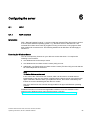
Configuring the server ............................................................................................................................. 81
6.1
6.1.1
6.1.2
RDP............................................................................................................................................. 81
RDP overview ............................................................................................................................. 81
Administration on the server ....................................................................................................... 82
6.2
VNC............................................................................................................................................. 83
6.3
Sm@rtServer .............................................................................................................................. 84
6.4
SINUMERIK ................................................................................................................................ 85
Operating the device................................................................................................................................ 87
7.1
Overview ..................................................................................................................................... 87
7.2
Front operator controls................................................................................................................ 88
7.3
7.3.1
7.3.2
7.3.3
7.3.4
Operating the taskbar.................................................................................................................. 89
Structure and functions of the taskbar ........................................................................................ 89
Starting a connection .................................................................................................................. 91
Changing from one connection to another.................................................................................. 92
Terminating a connection............................................................................................................ 93
7.4
Operating the on-screen keyboard ............................................................................................. 94
7.5
Operating a USB memory device ............................................................................................... 95
Industrial Thin Client ITC1200, ITC1500, ITC1900, ITC2200
6
Operating Instructions, 04/2013, A5E03474888-02
Table of contents
8
9
A
Device maintenance and repair ............................................................................................................... 97
8.1
Cleaning the device front .............................................................................................................97
8.2
Disabling the touch screen...........................................................................................................98
8.3
Calibrating the touch screen ........................................................................................................98
8.4
Spare parts and repairs ...............................................................................................................99
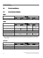
Technical specifications......................................................................................................................... 101
9.1
Certificates and approvals .........................................................................................................101
9.2
9.2.1
9.2.2
Directives and declarations........................................................................................................103
Electromagnetic compatibility ....................................................................................................103
ESD guideline ............................................................................................................................104
9.3
9.3.1
9.3.2
9.3.3
9.3.4
Dimensional drawings................................................................................................................106
Dimensional drawings of ITC1200 .............................................................................................106
Dimensional drawings of ITC1500 .............................................................................................107
Dimensional drawings of ITC1900 .............................................................................................108
Dimensional drawings of ITC2200 .............................................................................................109
9.4
9.4.1
9.4.2
9.4.3
9.4.3.1
9.4.3.2
9.4.3.3
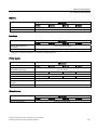
Technical specifications .............................................................................................................110
General technical specifications ................................................................................................110
Performance data ......................................................................................................................112
Ambient conditions.....................................................................................................................112
Transport and storage conditions ..............................................................................................112
Operating conditions ..................................................................................................................113
Information on insulation tests, protection class and degree of protection................................116
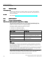
9.5
9.5.1
9.5.2
9.5.3
Description of the ports ..............................................................................................................117
Power supply..............................................................................................................................117
USB............................................................................................................................................117
PROFINET (LAN) 10/100/1000 Mb ...........................................................................................118
Technical Support.................................................................................................................................. 119
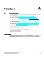
A.1
B
Service and support ...................................................................................................................119
Abbreviations......................................................................................................................................... 121
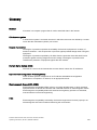
Glossary ................................................................................................................................................ 123
Index...................................................................................................................................................... 127
Industrial Thin Client ITC1200, ITC1500, ITC1900, ITC2200
Operating Instructions, 04/2013, A5E03474888-02
7
Table of contents
Industrial Thin Client ITC1200, ITC1500, ITC1900, ITC2200
8
Operating Instructions, 04/2013, A5E03474888-02
1
Overview
1.1
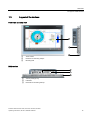
Product description
SIMATIC ITC - the high-performance local thin client solution
Industrial Thin Clients are low-cost HMI terminals that provide local HMI functionality in
plants spread over large areas. In this way, Industrial Thin Clients contribute to an improved
overview, operability, and productivity of plants. In addition, the Industrial Thin Clients also
reduce the total cost of ownership (TCO) by virtue of their extremely easy commissioning,
efficient Ethernet networking, reduced software costs, and minimal service costs.
The Industrial Thin Client always communicates with a host, such as an HMI device,
industrial PC, or server, via the following connection types:
● Web browser functionality
● SIMATIC WinCC Sm@rtServer
● Standard RDP (Remote Desktop Protocol) from Microsoft
● VNC (Virtual Network Computing)
● SINUMERIK connection
The Industrial Thin Client itself requires no installation and no licenses to operate. For
remote configuration, we offer the Management Software Remote Configuration Center at
(as of RCC V2.0). You can also bridge greater distances via Ethernet.
You can do the following from the Industrial Thin Client:
● Display and run web-based content from a web server available on the network (e.g., S7
controller, Intranet/Internet) via the integrated web browser.
● Run WinCC projects on other HMI devices or industrial PCs via Sm@rtServer.
● Run HMI applications (e.g., WinCC), Office applications (e.g., Excel), or SAP directly at
the machine via RDP.
● Operate a PC remotely with VNC (similar to RDP)
● Use the SINUMERIK connection to make the Industrial Thin Client a SINUMERIK Thin
Client Unit (TCU).
Hardware equipment
The device is available with 12", 15", 19", or 22" LCD TFT widescreen display with 16 million
colors. You operate the device via the touch screen or a keyboard/mouse connected to the
two USB ports.
In terms of the mounting cutout (width and height) and design, the Industrial Thin Client builtin units are compatible with the SIMATIC HMI Comfort Panels of the same size.
Industrial Thin Client ITC1200, ITC1500, ITC1900, ITC2200
Operating Instructions, 04/2013, A5E03474888-02
9
Overview
1.2 Product package
Easy commissioning
The Industrial Thin Client merely requires an IP address. For fast on-site commissioning and
diagnostics, the SIMATIC ITC is equipped with a Setup Wizard optimized for touch operation.
Alternatively, the Remote Configuration Center (RCC V2.0 or higher) management software
enables easy, efficient remote configuration and diagnostics of one or more devices. Local
software installation on the device is not necessary. The display and user interface of the
application are provided by the host.
High robustness
As a remote operator terminal without any rotating media (hard drive or fan), you can
operate the Industrial Thin Client on machines having stringent requirements for mechanical
robustness.
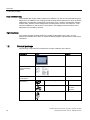
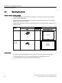
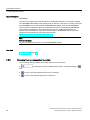
1.2
Product package
The following components are included in the scope of delivery of the device:
Designation
Figure
Quantity
HMI device
1
Installation instructions
1
(Quick Installation
Guide)
Remote Configuration
Center (RCC).
Mounting clamps with
threaded pin
Mains terminal
On CD
1
Aluminum mounting clamps
12
ITC1200
Steel mounting clamps
12
ITC1500
ITC1900
ITC2200
1
Industrial Thin Client ITC1200, ITC1500, ITC1900, ITC2200
10
Operating Instructions, 04/2013, A5E03474888-02
Overview
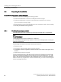
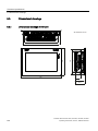
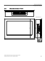
1.3 Layout of the devices
1.3
Layout of the devices
Front view and side view
①
②
③
Touch screen
Recesses for mounting clamps
Mounting seal
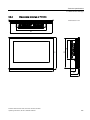
Bottom view
①
②
③
"Factory settings" key
Interfaces
Recesses for mounting clamps
Industrial Thin Client ITC1200, ITC1500, ITC1900, ITC2200
Operating Instructions, 04/2013, A5E03474888-02
11
Overview
1.3 Layout of the devices
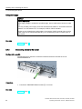
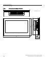
Rear view
①
②
③
④
⑤
1.3.1
Rating plate
Cover
Interface designation
Ground connection
Fixing elements for strain relief
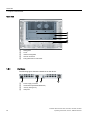
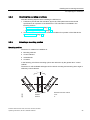
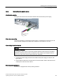
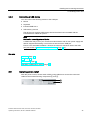
Interfaces
The following figure shows the interfaces on the device.
①
②
③
④
Power supply connector
LAN interface (PROFINET/Ethernet)
"Factory settings" key
USB ports
Industrial Thin Client ITC1200, ITC1500, ITC1900, ITC2200
12
Operating Instructions, 04/2013, A5E03474888-02
Overview
1.4 Accessories
1.4
Accessories
Accessories are not included in the scope of delivery of the HMI device, but can be ordered
on the Internet at Industry Mall (http://mall.automation.siemens.com).
This section provides information on the scope of accessories available at the time these
operating instructions were written.
Protective films
Designation
Order No.
Protective film set for ITC1200
6AV2124-6MJ00-0AX0
Protective film set for ITC1500
6AV2124-6QJ00-0AX0
Protective film set for ITC1900
6AV2124-6UJ00-0AX0
Protective film set for ITC2200
6AV2124-6XJ00-0AX0
Service packages
1.5
Designation
Order No.
Set of 20 aluminum mounting clamps for ITC1200
6AV6671-8XK00-0AX0
Set of 20 steel mounting clamps for ITC1500, ITC1900, and ITC2200
6AV6671-8XK00-0AX3
Set of 10 mains terminals
6AV6671-8XA00-0AX0
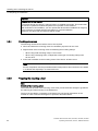
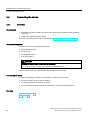
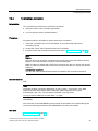
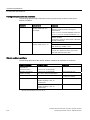
Typical applications
Industrial Thin Clients can be used as operator terminals in different scenarios. With the
Industrial Thin Client, for example, you can access an HMI device and hence control a work
process. You can also use the Industrial Thin Client to run Office applications on a server, for
example, on a PC and modern web applications.
Typical applications are presented in the following.
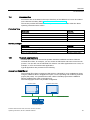
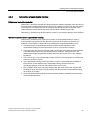
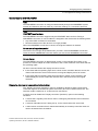
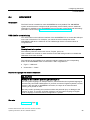
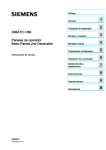
Access to a Sm@rtServer
The Industrial Thin Client accesses an HMI device or industrial PC as a Sm@rtServer client
using the SIMATIC WinCC Sm@rtServer option. You are operating and monitoring a WinCC
project (TIA portal). You operate and monitor a WinCC flexible project with the SIMATIC
WinCC Sm@rtAccess option in the same way.
The following figure shows one possible configuration.
&RPIRUW3DQHO
,QGXVWULDO7KLQ&OLHQW
352),1(7(WKHUQHW
$XWRPDWLRQV\VWHP
Industrial Thin Client ITC1200, ITC1500, ITC1900, ITC2200
Operating Instructions, 04/2013, A5E03474888-02
13
Overview
1.5 Typical applications
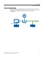
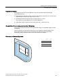
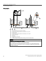
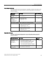
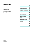
Access to a server via "RDP".
The Industrial Thin Client uses RDP (Remote Desktop Protocol) to access a server, such as
an industrial PC or a PC. The following applications are also possible.
● WinCC/Web Navigator
The Industrial Thin Client uses an Internet browser on the server to access the WinCC
Web Navigator as a Web Navigator client. In this case, the operating system Windows
Server 2003 or 2008 must be installed on the server. For more information, refer to the
documentation for the WinCC/Web Navigator option.
● The Industrial Thin Client accesses an Office application (e.g., MS Excel) or SAP
application on the server. In contrast to the Windows Server operating systems, you can
only operate one screen with Windows XP and Windows 7. The other monitor is always
blocked.
● The Industrial Thin Client accesses an Office application running in Windows Server 2003,
(e.g., MS Excel) or SAP application on the server.
The following figure shows one possible configuration with the Windows Server operating
system on an Industrial PC or a PC.
,QGXVWULDO3&V
,QGXVWULDO
7KLQ&OLHQW
,QGXVWULDO
7KLQ&OLHQW
,QGXVWULDO
7KLQ&OLHQW
,QGXVWULDO
7KLQ&OLHQW
,QGXVWULDO
7KLQ&OLHQWQ
352),1(7(WKHUQHW
$XWRPDWLRQV\VWHP
Access to a server via "VNC"
You use VNC in a similar way as RDP to remotely monitor and run a PC and to monitor its
screen outputs. In contrast to RDP, all clients display the same server screen.
Access to SINUMERIK
The Industrial Thin Client accesses the SINUMERIK system network through the
SINUMERIK connection. The system network configures the Industrial Thin Client to be a
SINUMERIK Thin Client Unit (TCU). You use the TCU for operator control and monitoring of
a SINUMERIK PCU or SINUMERIK NCU.
Industrial Thin Client ITC1200, ITC1500, ITC1900, ITC2200
14
Operating Instructions, 04/2013, A5E03474888-02
Overview
1.5 Typical applications
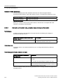
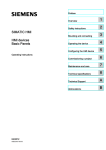
Access to a web server via "Web"
The Industrial Thin Client displays applications and the content of a web server using the
integrated web browser functionality . Web-based content may be diagnostic or user-specific
web pages of an S7 controller (PROFINET), for example, or content from the
Intranet/Internet.
,QWHUQHW
,QGXVWULDO3&V
7&3,3,QWHUQHW
352),1(7(WKHUQHW
$XWRPDWLRQV\VWHP
,QGXVWULDO
7KLQ&OLHQW
$XWRPDWLRQV\VWHP
Industrial Thin Client ITC1200, ITC1500, ITC1900, ITC2200
Operating Instructions, 04/2013, A5E03474888-02
15
Overview
1.6 Requirements
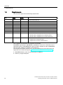
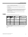
1.6
Requirements
The connection types have the following requirements:
RDP
Sm@rt
Server
Sm@rt
Access
X
Windows XP Professional
Windows 7 Home
X
Windows 7 Professional
X
Windows 7 Ultimate
X
Windows Server 2003
X
Windows Server 2008
X
Windows Server 2008 R2
X
Windows Embedded Standard 7
X
Windows Embedded Standard 2009
X
As of SIMATIC WinCC V11 (TIA portal) with the options:
X
SIMATIC WinCC Sm@rtServer for SIMATIC Panels
SIMATIC WinCC Sm@rtServer for Runtime Advanced
SIMATIC WinCC flexible 2008 SP1 with the option:
Sm@rtAccess for SIMATIC Panel
Sm@rtAccess for WinCC flexible Runtime
VNC: TightVNC and UltraVNC are supported, for example.
SINUMERIK requirements: SINUMERIK is available as of V4.5 SP2. Information on the
supported version of SINUMERIK PCU with PCU basic software as well as SINUMERIK
NCU with CNC software is available on the Internet at
"http://support.automation.siemens.com" (see Service&Support portal under Technical
Support/for short Technical Support (http://www.siemens.de/automation/csi_en_WW)):
● SINUMERIK Hotline: same "Access channels" as SIMATIC.
● Online: by "Support Request".
Industrial Thin Client ITC1200, ITC1500, ITC1900, ITC2200
16
Operating Instructions, 04/2013, A5E03474888-02
Safety instructions
2.1
2
General safety instructions
Open equipment and the Machinery Directive
WARNING
The device constitutes open equipment
The device constitutes open equipment. This means that the device may only be installed
in enclosures or cabinets which provide front access for operating the device.
Access to the enclosure or cabinet in which the device is installed should only be possible
by means of a key or tool and for trained and authorized personnel.
Electrocution risk when control cabinet is open
When you open the control cabinet, there may be a dangerous voltage at certain areas or
components.
Touching these areas or components can cause electrocution.
Always disconnect the cabinet from the mains before opening it.
The device may only be used in machines which comply with the Machinery Directive
The Machinery Directive specifies precautions to be taken when commissioning and
operating machinery within the European Economic Area.
Failure to follow these precautions is a breach of the Machinery Directive. Such failure may
also cause personal injury and damage depending on the machine operated.
The machine in which the HMI device is to be operated must conform to Directive
2006/42/EC.
Hazardous areas
When operating the HMI device in hazardous areas the following warning applies.
WARNING
Explosion Hazard
Do not disconnect while circuit is live unless area is known to be non-hazardous.
Substitution of components may impair suitability for Class I, Division 2 or Zone 2.
Risque d'Explosion
Ne pas déconnecter pendant que le circuit est sous tension, sauf si la zone est nondangereuse. Le remplacement de composants peut compromettre leur capacité à satisfaire
à la Classe I, Division 2 ou Zone 2.
Industrial Thin Client ITC1200, ITC1500, ITC1900, ITC2200
Operating Instructions, 04/2013, A5E03474888-02
17
Safety instructions
2.2 Security information
High frequency radiation
NOTICE
Unwanted operating states
High-frequency radiation, for example from cellular phones, interferes with device functions
and can cause device malfunction.
This causes injury and damages the system.
Avoid high-frequency radiation:
Remove the sources of radiation from the vicinity of the device.
Switch off radiating devices.
Reduce the radio output of radiating devices.
Observe the information on electromagnetic compatibility (Page 113).
2.2
Security information
Siemens offers IT security mechanisms for its portfolio of automation and drive products in
order to support safe operation of the plant/machine. We recommend that you stay informed
about the IT security developments for your products. For information on this topic, refer to:
Industry Online Support (http://www.siemens.de/automation/csi_en_WW): You can register
for a product-specific newsletter here.
For the safe operation of a plant/machine, however, it is also necessary to integrate the
automation components into an overall IT security concept for the entire plant/machine,
which corresponds to the state-of-the-art IT technology. You can find information on this
under: Industrial Security (http://www.siemens.com/industrialsecurity).
Products used from other manufacturers should also be taken into account here.
Remote maintenance is not recommended for production and should be disabled before
production is started.
The remote maintenance settings are disabled by default. If you enable them for
maintenance purposes, disable the remote maintenance settings once again for production
in the start menu "Configuration > System", "Remote maintenance" (see configuration
settings, section "System settings").
If you use Remote configuration in production, we recommend using your own, private key
for security reasons (see section "Remote configuration of several devices", "Key
assignment").
If you are using a private key, the remote configuration service is only guaranteed from a PC
with installed private key file. Assign a password for logging on to the PC.
The Remote configuration service (SSH) is enabled by default. If you do not need remote
configuration, disable remote configuration in the system settings of the device during
production (see section "Remote configuration of several devices", "Securing remote
configuration").
Industrial Thin Client ITC1200, ITC1500, ITC1900, ITC2200
18
Operating Instructions, 04/2013, A5E03474888-02
3
Installing and connecting the device
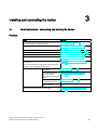
3.1
Brief instructions - connecting and starting the device
Procedure
Step
See also
Place the device in the mounting cutout, and fasten the Mounting the device (Page 24)
HMI device with the mounting clamps.
Connect the equipotential bonding.
Connection of equipotential bonding
(Page 27)
Connect the power supply.
Connecting the power supply (Page 29)
Connect PROFINET/Ethernet.
Connecting device to the server (Page 30)
Optional: Connect an external USB device.
Connecting a USB device (Page 31)
Switch on the power supply.
Switching on and testing the device
(Page 33)
Start the Setup wizard and follow the instructions on
the screen.
Structure and functions of the taskbar
(Page 89)
You can also open the configuration settings from the
taskbar in the "Configuration" Start menu.
Select the network
connection.
Network settings (Page 46)
Enter the IP addresses
Setting up client-server connections
and further access
(Page 53)
parameters of the required
server.
Create a new
administrator password.
Password settings (Page 58)
Close the dialog with
"Save" or "Exit".
Start the required client-server connection.
Structure and functions of the taskbar
(Page 89)
Industrial Thin Client ITC1200, ITC1500, ITC1900, ITC2200
Operating Instructions, 04/2013, A5E03474888-02
19
Installing and connecting the device
3.2 Preparing for installation
3.2
Preparing for installation
Select the mounting location of the HMI device
Points to observe when selecting the mounting location:
● Position the HMI device so that it is not subjected to direct sunlight.
● Position the HMI device such that it is ergonomically accessible for the operator.
Choose a suitable mounting height.
● Ensure that the air vents of the HMI device are not covered as a result of the mounting.
● Note the permissible mounting positions.
3.2.1
Checking the package contents
Check the package content for visible signs of transport damage and for completeness.
Note
If a part is damaged
A damaged part will cause the HMI device to malfunction.
Do not install parts damaged during shipment. In the case of damaged parts, contact your
Siemens representative.
The following is included in the scope of delivery of the device:
● The device itself
● Accessory kit with mounting clamps and mains terminal
● CD with RCC remote configuration software and the source codes for the open source
software
● Additional documents as required
The documentation belongs to the device and is required for subsequent commissioning.
Retain all enclosed documentation for the entire service life of the HMI device. You must
pass on the enclosed documentation to any subsequent owner or user of the HMI device.
Make sure that every supplement to the documentation that you receive is stored together
with the operating instructions.
Industrial Thin Client ITC1200, ITC1500, ITC1900, ITC2200
20
Operating Instructions, 04/2013, A5E03474888-02
Installing and connecting the device
3.2 Preparing for installation
3.2.2
Checking the operating conditions
Note the following aspects before installing the HMI device:
1. Familiarize yourself with the standards, approvals, EMC parameters and technical
specifications for operation of the HMI device. This information is available in the
following sections:
– Certificates and approvals (Page 101)
– Electromagnetic compatibility (Page 103)
2. Check the mechanical and climatic ambient conditions for operation of the HMI device:
Ambient conditions (Page 112).
3.2.3
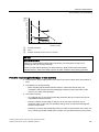
Selecting a mounting position
Mounting position
The device is suitable for installation in:
● Mounting cabinets
● Control cabinets
● Switchboards
● Consoles
In the following, all of these mounting options are referred to by the general term "control
cabinet".
The device is self-ventilated and approved for vertical mounting and mounting at an angle in
stationary control cabinets.
–
①
②
+
Mounting position
Deviation from the vertical
Inclined
≤ 35°
Vertical
0°
Industrial Thin Client ITC1200, ITC1500, ITC1900, ITC2200
Operating Instructions, 04/2013, A5E03474888-02
21
Installing and connecting the device
3.2 Preparing for installation
NOTICE
Damage due to overheating
Convection through the device is reduced when it is installed at an angle. This means that
the maximum permitted ambient temperature for operation is also reduced.
With sufficient forced ventilation, you can operate the device when installed at an angle up
to the maximum permitted ambient temperature for vertical installation.
Otherwise, the approvals and warranty will be voided.
3.2.4
Checking clearances
The following clearances around the device are required:
● Above and below the mounting cutout for ventilation purposes: 50 mm each
● Right and left of the mounting cutout for attaching the mounting clamps:
– When using metal mounting clamps: 15 mm each
– When using a clamping frame, independent of the type of mounting clamp used:
25 mm each
● At the rear in addition to the mounting cutout of the device: at least 10 mm
Note
Ensure compliance with the permissible ambient temperature when the device is installed
in a cabinet and especially in a closed enclosure.
3.2.5
Preparing the mounting cutout
Note
Stability of the mounting cutout
The material in the area of the mounting cutout must provide sufficient strength to guarantee
the enduring and safe mounting of the HMI device.
The force of the clamps or operation of the device may not lead to deformation of the
material in order to achieve the degrees of protection described below.
Industrial Thin Client ITC1200, ITC1500, ITC1900, ITC2200
22
Operating Instructions, 04/2013, A5E03474888-02
Installing and connecting the device
3.2 Preparing for installation
Degrees of protection
The degrees of protection of the HMI device can only be guaranteed if the following
requirements are met:
● Material thickness at the mounting cutout for IP65 degree of protection or Front face only
Type 4X/Type 12 (indoor use only): 2 mm to 6 mm
● Permitted deviation from plane at the mounting cutout: ≤ 0.5 mm
This condition must be fulfilled for the mounted HMI device.
● Permissible surface roughness in the area of the seal: ≤ 120 µm (Rz 120)
Compatibility of the mounting cutout to other HMI devices
The mounting cutouts of all devices with widescreen display of comparable display size are
compatible.
Keep in mind that even though the dimensions of the mounting cutout are identical, the
device depth and/or enclosure front dimensions may differ from the corresponding
dimensions of the predecessor devices and other widescreen displays.
Dimensions of the mounting cutout
w
+1
0
h
+1
0
,7&
,7&
,7&
,7&
w
h
Industrial Thin Client ITC1200, ITC1500, ITC1900, ITC2200
Operating Instructions, 04/2013, A5E03474888-02
23
Installing and connecting the device
3.3 Mounting the device
3.3
Mounting the device
Position of the mounting clamps
To achieve the degree of protection for the device, you need to comply with the mounting
clamp positions listed below.
The positions of the mounting clamps are marked by stamps on the cutouts. Fit mounting
clamps in all the stamped cutouts.
The following table shows the type, number and position of mounting clamps needed for the
various devices.
Device
ITC1200
Mounting clamps
Type
Quantity
Aluminum mounting clamps
12
Position on the device
,7&
ITC1500
Steel mounting clamps
12
ITC1900
ITC2200
,7&
,7&
,7&
Requirement
● All packaging components and protective films have been removed from the device.
● To install the device, you need the mounting clamps from the accessory kit.
● Ensure that the mounting seal is attached to the device.
Industrial Thin Client ITC1200, ITC1500, ITC1900, ITC2200
24
Operating Instructions, 04/2013, A5E03474888-02
Installing and connecting the device
3.3 Mounting the device
Procedure
Note
Risk of guaranteed degree of protection not being met
If the mounting seal is damaged or protrudes beyond the device, the degree of protection is
not ensured.
Checking the placement of the mounting seal
To avoid leakage around the mounting cutout, do not install the mounting seal turned inside
out. If the mounting seal is damaged, order a replacement seal.
Note
Installing the device
Always mount the device according to the instructions in this manual.
Mounting clamps for ITC1200:
Mounting clamps for ITC1500, ITC1900, and
ITC2200:
Proceed as follows:
1. Working from the front, insert the device into the mounting cut-out.
2. Insert the mounting clamp into the cutout provided on the device.
3. Secure the mounting clamp by tightening the threaded pin.
Note
Observe a torque of 0.5 Nm when tightening the threaded pins of the mounting clamps:
4. Repeat steps 2 and 3 for all mounting clamps.
5. Check the fit of the mounting seal.
Result
The device is mounted and the degree of protection is ensured at the front.
Industrial Thin Client ITC1200, ITC1500, ITC1900, ITC2200
Operating Instructions, 04/2013, A5E03474888-02
25
Installing and connecting the device
3.4 Connecting the device
3.4
Connecting the device
3.4.1
Overview
Requirement
● The device has been installed according to the information provided in these operating
instructions.
● Always use shielded standard cables.
For order information please refer to Industry Mall (http://mall.automation.siemens.com).
Connection sequence
Connect the device in the following sequence:
1. Equipotential bonding
2. Power supply
3. PROFINET/Ethernet
4. I/Os as necessary
CAUTION
Damage in case of incorrect connection sequence
You must connect the device in the sequence indicated above.
Disconnect the device by completing the above steps in reverse order.
Connecting the cable
● When connecting the cables, ensure that the contact pins are not bent.
● Secure the cable connector with a cable tie.
● Provide adequate strain relief for all cables.
● The pin assignment of the interfaces is described in the technical specifications.
See also
Power supply (Page 117)
USB (Page 117)
Industrial Thin Client ITC1200, ITC1500, ITC1900, ITC2200
26
Operating Instructions, 04/2013, A5E03474888-02
Installing and connecting the device
3.4 Connecting the device
3.4.2
Connection of equipotential bonding
Differences in electrical potential
Differences in electrical potential can develop between spatially separated plant components.
Such electrical potential differences can lead to high equalizing currents over the data cables
and therefore to the destruction of their interfaces. Equalizing currents can develop if the
cable shielding is terminated at both ends and grounded to different plant parts.
Differences in potential may develop when a system is connected to different mains supplies.
General requirements for equipotential bonding
Differences in potential must be reduced by means of equipotential bonding in order to
ensure trouble-free operation of the relevant components of the electronic system. The
following must therefore be observed when installing the equipotential bonding circuit:
● The effectiveness of equipotential bonding increases as the impedance of the
equipotential bonding conductor decreases or as its cross-section increases.
● If two plant parts are interconnected by means of shielded data cables and their shielding
is bonded at both ends to the grounding/protective conductor, the impedance of the
additionally installed equipotential bonding cable must not exceed 10% of the shielding
impedance.
● The cross-section of an equipotential bonding conductor must be capable of handling the
maximum equalizing current.
● Use equipotential bonding conductors made of copper or galvanized steel. Establish a
large surface contact between the equipotential bonding conductors and the
grounding/protective conductor and protect these from corrosion.
● Use a suitable cable clip to clamp the shield of the data cable flush to the equipotential
bonding rail. Keep the length of cable between the device and the equipotential bonding
rail as short as possible.
● Route the equipotential bonding conductor and data cables in parallel and with minimum
clearance between these.
Industrial Thin Client ITC1200, ITC1500, ITC1900, ITC2200
Operating Instructions, 04/2013, A5E03474888-02
27
Installing and connecting the device
3.4 Connecting the device
Wiring diagram
①
②
③
④
⑤
⑥
⑦
⑧
Ground connection on the device, example
Equipotential bonding conductor cross-section: min. 4 mm2
Control cabinet
Equipotential bonding conductor cross-section: min. 16 mm2
Ground connection
Cable clip
Equipotential bonding rail
Parallel routing of the equipotential bonding conductor and data cable
NOTICE
Damage to the interface modules possible
Cable shielding is not suitable for equipotential bonding.
Use only the prescribed equipotential bonding conductors. The equipotential bonding
conductor ④ must not be less than 16 mm². The interface modules may otherwise be
damaged or destroyed.
Industrial Thin Client ITC1200, ITC1500, ITC1900, ITC2200
28
Operating Instructions, 04/2013, A5E03474888-02
Installing and connecting the device
3.4 Connecting the device
3.4.3
Connecting the power supply
Configuration graphic
The figure below shows the connection between the device and the power supply.
'&9
*1'
Note when connecting
The mains terminal for connecting the power supply is contained in the accessory kit. The
mains terminal is designed for cables with a maximum cross-section of 1.5 mm².
Connecting the mains terminal
NOTICE
Damage to the socket
If you tighten up the screws on the mains terminal while the mains terminal is inserted in
the device, then the pressure of the screwdriver on the socket may damage the device.
Only connect the wires when the mains terminal is withdrawn.
1. Connect the power supply terminal to the cables of the power supply as shown in the
figure above.
2. Ensure that the cables are connected to the correct terminals. Refer to the label for the
contact pins on the rear of the device.
Reverse polarity protection
The device is equipped with reverse polarity protection.
Industrial Thin Client ITC1200, ITC1500, ITC1900, ITC2200
Operating Instructions, 04/2013, A5E03474888-02
29
Installing and connecting the device
3.4 Connecting the device
Safe power supply
NOTICE
Device malfunction
If the supply voltage is outside the specified range, device malfunctions cannot be ruled
out.
Use only 24 VDC power supply units with safe electrical isolation in accordance with IEC
60364-4-41 or HD 60364-4-41, for example, to SELV / PELV standard.
Applies to non-isolated plant configurations: Connect the "GND" terminal of the 24 VDC
power supply to the equipotential bonding. You should always select a central point of
termination.
See also
Interfaces (Page 12)
3.4.4
Connecting device to the server
Configuration graphic
The following figure shows the connection between the device and the server via
PROFINET/Ethernet.
Procedure
1. Connect the PROFINET/Ethernet cable ① to a server.
See also
Interfaces (Page 12)
Industrial Thin Client ITC1200, ITC1500, ITC1900, ITC2200
30
Operating Instructions, 04/2013, A5E03474888-02
Installing and connecting the device
3.5 Installing strain relief
3.4.5
Connecting a USB device
You can connect the following devices to the USB port:
● Mouse
● Keyboard
● Industrial USB Hub 4
● USB memory devices
The device only supports USB storage devices that have been formatted with the
FAT16/FAT32 or NFTS file system.
Note
Malfunction caused by external device
A malfunction may occur if you connect an external device with its own power supply and
without equipotential bonding or excessive current load to the USB port.
Ensure a non-insulated installation. Observe the values for maximum load of the USB
port (see section "General technical specifications (Page 110)").
See also
Interfaces (Page 12)
USB (Page 117)
SINUMERIK (Page 85)
Operating a USB memory device (Page 95)
3.5
Installing strain relief
After the power-on test, ensure strain relief by using cable ties to secure the connected
cables to the marked mounting components ① and ②.
Industrial Thin Client ITC1200, ITC1500, ITC1900, ITC2200
Operating Instructions, 04/2013, A5E03474888-02
31
Installing and connecting the device
3.5 Installing strain relief
Industrial Thin Client ITC1200, ITC1500, ITC1900, ITC2200
32
Operating Instructions, 04/2013, A5E03474888-02
Commissioning the device
4.1
4
Switching on and testing the device
Procedure
Proceed as follows:
1. Switch on the power supply.
Information regarding the included free software is displayed during startup.
If the device fails to start, you may have crossed the wires on the mains terminal. Check
the connected wires and change their connection.
Additional information is available in the configuration settings, Section Basics (Page 50).
Make sure that you observe the warning at the end of the section.
Setup Wizard
The first time the device starts up, the Setup Wizard remains open until the configuration
settings become valid. The Setup Wizard guides you through the configuration of selected
device and network data as well as passwords and connection settings.
The Setup Wizard starts again when the factory settings are restored or the firmware is
updated.
Function test
Perform a function test following commissioning. The device is functional if one of the
following states occurs:
● The taskbar is displayed.
● The configured startup connections are established.
Procedure - Switching off the device
Proceed as follows:
1. Terminate all client-server connections and close all programs.
2. Switch off the power supply.
Restart
You restart the device, for example, in order to test the startup connections.
When the "Restart" menu command is hidden, select "Permit restart" (see section "Password
settings (Page 58)").
1. Choose "Restart" from the task bar in the start menu. A confirmation prompt is displayed
first.
2. Click "Yes" to confirm. The device restarts.
Industrial Thin Client ITC1200, ITC1500, ITC1900, ITC2200
Operating Instructions, 04/2013, A5E03474888-02
33
Commissioning the device
4.2 Interrupting and restoring a connection
4.2
Interrupting and restoring a connection
Introduction
The connection to the server can be interrupted in several ways:
● The server is offline or has has not completed its startup sequence.
● The password is incorrect.
● A firewall is blocking server access.
● The SINUMERIK server does not support the Industrial Thin Client, for example, if the
firmware on the server is outdated.
● The server has been shut down, for example, for maintenance purposes.
● The PROFINET/Ethernet network cable has been disconnected.
● A connection problem occurred in the network.
● A client-server connection was started on another device which logs onto the server with
the same data. The client-server connection running on your device is then terminated.
Note that there can be multiple client-server connections at one time.
Automatic connection establishment
The device tries to re-establish the interrupted connection automatically. There are two basic
standard cases for this:
● Initial start of a connection
The connection cannot be established because the server is not ready, for example. The
device makes continuous attempts to establish the connection to the server.
● Existing connection
An existing connection to the server is interrupted because the network cable has been
removed or the network is faulty, for example.
The device makes continuous attempts to re-establish the connection to the server.
Exception: If the device receives a message via the network, for example when the
server is shut down, the device terminates the current client-server connection.
Afterwards, the device will only try to re-establish the interrupted connection to the server
if the "Reconnect automatically" option is selected in the configuration settings.
Terminate the active connection in order to cancel the attempts to establish a connection.
Special features
SINUMERIK
Initial start of a connection: Maximum of 40 connection attempts. Then the SINUMERIK
connection is terminated and the configuration settings are restored.
Existing connection: Automatic connection establishment. After the connection has been
canceled, the message "Waiting for HMI" appears.
Industrial Thin Client ITC1200, ITC1500, ITC1900, ITC2200
34
Operating Instructions, 04/2013, A5E03474888-02
Assigning device parameters
5.1
5
Possible applications
Possible applications
The Industrial Thin Client can fulfill the following functions as an operator terminal:
● Access to an HMI device as a Sm@rtServer client via the WinCC Sm@rtServer option.
● Access as a client via the "RDP" protocol (Windows programs).
● Access as a client via the "VNC" protocol (Windows programs).
● Access to a SINUMERIK PCU or NCU as a SINUMERIK Thin Client Unit (TCU).
● Access as a web client to a web server, e.g. of an S7 controller or the Intranet.
When the device accesses a server, for example, an HMI device or a PC, as a client, the
screen display of the server is shown on the screen of the Industrial Thin Client. The user
uses the Industrial Thin Client to access programs or projects on the server.
Note
The documentation refers to "Sm@rtServer", "RDP", "VNC", "SINUMERIK" and "Web" as
connection types.
5.2
Opening the configuration
Introduction
You set the device parameters in the Configuration settings of the device (Page 38).
Note
You can edit the configuration settings of the device as follows:
Either directly on the device or
Remotely via PC at your convenience (see section "Remote configuration of several
devices (Page 66)"). The settings then appear in a separate configuration window on the
right and on the device itself.
In the remote configuration, you can also edit several devices at the same time (see section
"Overview of remote operation (Page 69)").
Restart devices
Update firmware
Assign IP addresses, etc.
Industrial Thin Client ITC1200, ITC1500, ITC1900, ITC2200
Operating Instructions, 04/2013, A5E03474888-02
35
Assigning device parameters
5.2 Opening the configuration
Procedure on the device
1. Press the
"Start menu" symbol in the task bar.
2. Select the menu entry "Configuration". At first, all configuration settings are displayed in
the "All" submenu. Detailed information is available in the section "Access and structure
(Page 38)".
3. Go left to another submenu, for example "Information". The device information is
displayed (see section "Device data (Page 40)").
4. Close the configuration settings with the
"Exit" symbol.
You can find additional menu entries in the Start menu and a description of the task bar in
the section "Structure and functions of the taskbar (Page 89)".
Industrial Thin Client ITC1200, ITC1500, ITC1900, ITC2200
36
Operating Instructions, 04/2013, A5E03474888-02
Assigning device parameters
5.2 Opening the configuration
NOTICE
Unintended reactions of the device
Two people can edit the configuration settings simultaneously: locally on the device and via
remote configuration. The most recently saved settings are the valid settings at any given
time (blue "Save" symbol).
Organize access to the configuration settings in such a way that only one person can edit
the configuration settings at one time.
Note
Unauthorized access
The factory-set administrator password is "admin" and is visible during administrator logon.
This means unauthorized personnel can log on and have free access to the configuration
settings and client-server connections.
After initial commissioning or restoring of the factory settings, you should log on with "admin"
and assign a new administrator password.
SSH configuration service
Note
Unauthorized access
Certain services are activated with the factory setting, for example, the SSH configuration
service which enables remote configuration. This means unauthorized personnel can log on
via SSH and have free access to the devices and client-server connections.
If you do not need the remote configuration service, disable it in the System settings
(Page 41).
Access without logon
If you are not logged on, you only have read access to the currently valid network settings
and the device data such as the IP address and the MLFB of the device (see section "Device
data (Page 40)").
See also
Disabling the touch screen (Page 98)
Calibrating the touch screen (Page 98)
Operating a USB memory device (Page 95)
Switching on and testing the device (Page 33)
Starting a connection (Page 91)
Password settings (Page 58)
Industrial Thin Client ITC1200, ITC1500, ITC1900, ITC2200
Operating Instructions, 04/2013, A5E03474888-02
37
Assigning device parameters
5.3 Configuration settings of the device
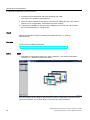
5.3
Configuration settings of the device
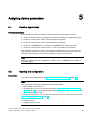
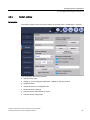
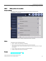
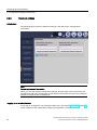
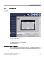
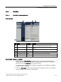
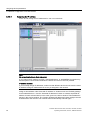
5.3.1
Access and structure
Structure
The following figure shows the configuration settings in the "Configuration" Start menu.
This configuration settings have the following submenus:
● "All": displays all configuration settings in a single window
● System settings under "System":
– Update firmware
– Back up and reload the configuration file
– Restore to factory settings
● Network settings under "Network"
● Connection settings under "Connections":
configures client-server connections for remote access
● Administrator password and connection password under "Passwords"
Industrial Thin Client ITC1200, ITC1500, ITC1900, ITC2200
38
Operating Instructions, 04/2013, A5E03474888-02
Assigning device parameters
5.3 Configuration settings of the device
● Desktop settings under "Desktop":
– Taskbar
– On-screen keyboard
– Background image
● Application settings under "Applications": Web browser settings
Note
Forced termination of connection
When you change and save the configuration settings, all open client-server connections
are terminated and all open programs are closed without a confirmation prompt. The
autostart connections are re-established afterwards and the new configuration settings
are put into effect.
Access without logon
If you open the configuration settings and do not log on as administrator, only "Configuration
> Information" is shown in the Start menu with the current network settings and device
information.
You have read-only access to the device and network data and cannot make any changes.
Access with logon
In order to view and edit the configuration settings (read and write access), you must log on
with a valid administrator password.
Note
Permanent data
Some data cannot be configured, for example, "MLFB number", "Firmware version", "MAC
address", etc.
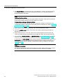
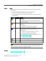
Symbols
Use the symbols above to manipulate the configuration settings.
You can
● ① "Log on" as an administrator and "Log off" again
● ② "Restart" the device.
● ③ "Save" the configuration settings
● ④ Open "Help".
● ⑤ "Exit" the configuration.
Industrial Thin Client ITC1200, ITC1500, ITC1900, ITC2200
Operating Instructions, 04/2013, A5E03474888-02
39
Assigning device parameters
5.3 Configuration settings of the device
See also
5.3.2
Network settings (Page 46)
System settings (Page 41)
Password settings (Page 58)
Setting up startup connection (Page 56)
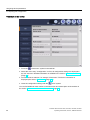
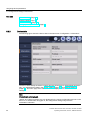
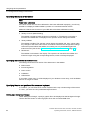
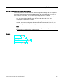
Device data
The following figure shows the device data in the Start menu "Configuration > Information".
The device data identify the device uniquely and are shown here for informational purposes
only. You edit the device data in the System settings (Page 41) and Network settings
(Page 46). The home page of the web browser also displays device data and network
settings.
Note
Information is not displayed.
"Status" and "Status message" are only displayed in the remote configuration and not on the
device. If no administrator is logged on, the configuration settings only show the
"Information" submenu.
Industrial Thin Client ITC1200, ITC1500, ITC1900, ITC2200
40
Operating Instructions, 04/2013, A5E03474888-02
Assigning device parameters
5.3 Configuration settings of the device
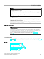
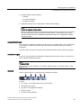
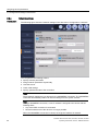
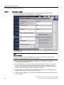
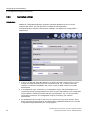
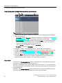
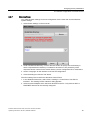
5.3.3
System settings
Introduction
The following figure shows the system settings in the Start menu "Configuration > System".
You can perform the following actions:
● Specify device name
● Setting up screen: language, brightness, calibration, right mouse click
● Update firmware
● Save and restore the configuration file
● Restore to factory settings
● Perform remote maintenance on device
● Activate remote configuration
Industrial Thin Client ITC1200, ITC1500, ITC1900, ITC2200
Operating Instructions, 04/2013, A5E03474888-02
41
Assigning device parameters
5.3 Configuration settings of the device
Specifying device name
In the "Device information" area, specify a name for the Industrial Thin Client in "Device
name". This name will allow the administrator to identify the device. The device name will be
displayed at the following places:
● In the title bar of the configuration settings
● In the case of Remote configuration of several devices (Page 66), in the device window
that lists the Industrial Thin Clients found in the network.
● As the PROFINET station name in SIMATIC Manager
The device name is also the PROFINET station name and must meet the following
conditions:
● One or more identifiers separated by a dot.
● Length of identifier: 1-63 characters
● Length of the device name: 1-255 characters, but only up to 26 characters are displayed
on the device
● The identifiers contain lower case letters a-z and numbers 0-9.
● The identifiers cannot start or not end with "-".
● The first identifier does not have the form "port-xyz" or "port-xyz-abcde" where a, b, c, d,
e, x, y, z = numbers 0 to 9.
● Identifiers do not start with "xn--" if RFC 3490 is applied.
● The device name may not end with "0".
● The device name does not have the n.n.n.n format, where n = 0 to 999.
Devices with more than one Ethernet interface do not need more than one device name.
Only up to 23 characters of the comment are displayed on the device (see above).
Setting up screen
Set the system language that includes the following texts under "Language":
● Start menu and settings
● On-screen keyboard and externally attached USB keyboard
● Messages
CAUTION
Damage to the machine or plant through operating error
The set system language, for example German, also determines the keyboard language of
the externally connected USB keyboard. If you then connect an English keyboard, however,
such as is the case with a SINUMERIK connection, the keys do not have the same
meaning as is printed on them.
This may result in operating errors at the machine and personal injury or damage to the
machine or plant. To connect an English keyboard, set the system language to English
under "Language" in the Start menu "Configuration > System".
Industrial Thin Client ITC1200, ITC1500, ITC1900, ITC2200
42
Operating Instructions, 04/2013, A5E03474888-02
Assigning device parameters
5.3 Configuration settings of the device
Set the "Screen brightness". You can also use the system settings to "Calibrate touch
screen" (see section "Calibrating the touch screen (Page 98)").
If you select the "Right mouse click" option, each contact on the touch screen lasting more
than 2 seconds will be interpreted as a right-click.
Example: If you touch the "Workstation" icon in Windows for more than 2 seconds, the
operating system or application will respond as though you had right-clicked the icon: the
context menu is displayed where you can select the "Properties" item, for example.
Update firmware
You update the device firmware either directly on the device via USB or from a PC via
Remote configuration of several devices (Page 66).
NOTICE
Data loss during firmware update
All configuration settings are lost during a firmware update. The factory settings are
restored after the update, which also resets passwords and calibration information.
Save the configuration file before you update the firmware and reload it after the update
(see below).
NOTICE
Damage to the device
If the power supply or the connection to the device containing the firmware is interrupted
during the update process, the device may no longer be functional.
Ensure that the power supply and the connection to the device are maintained during
the entire updating process.
Make sure that all applications running on the device are closed.
Before updating the firmware, restart the device to prevent memory problems.
In the "Device configuration" area, use the "Update" button to select an update file "*.upd".
The selected file will be transferred to the device. To determine whether the selected file is
suitable for the device, the system checks it against the following criteria, for example:
● The selected file is an update file.
● The selected update file is more current than the version installed on the device.
● The selected update file is suitable for this device.
If all the criteria are met, the selected update file will be run on the device. The device and
the Setup Wizard restart automatically.
Note
The progress of the update is displayed on the screen.
Industrial Thin Client ITC1200, ITC1500, ITC1900, ITC2200
Operating Instructions, 04/2013, A5E03474888-02
43
Assigning device parameters
5.3 Configuration settings of the device
Save and restore the configuration file
You back up the configuration file of the device either directly on the device via USB or from
a PC via Remote configuration of several devices (Page 66).
The configuration file contains all device-specific configuration settings with the exception of
the background image and the touch calibration. You can back up the configuration file of a
device and reload it to several devices, for example:
● Use the "Save" button to back up the configuration file for the device to the connected
drive. To do this, you select a folder in the file system and close the dialog with "OK". The
configuration file is saved to the folder.
● Use the "Restore" button to reload the backed up configuration file from the connected
USB drive, for example, if the current configuration file has been inadvertently overwritten.
To do this, you select a configuration file from a file dialog and close the dialog with "OK".
The syntax within the configuration file is checked. If the syntax is free of errors, the
configuration file will be transferred to the device and the old configuration file will be
overwritten; otherwise a message will be output.
Note
Saving the configuration file
Configuration files of the older version V1.x are no longer supported. Back up the current
configuration file before and after each firmware update.
Restoring the configuration file
Only restore configuration files that were created on the device or with the Remote
Configuration Center. A configuration file may not be altered after backup, for example,
by means of an editor.
IP address conflicts
Do not restore configuration files with the same IP addresses on different devices.
Reassign the IP addresses.
Restore to factory settings
Restoring factory settings has the following effects:
● The default configuration file overwrites the configuration file. All connection data for the
network, remote access and web browser is reset. The language and screen brightness,
the settings and position of the taskbar and on-screen keyboard, and the background
image are reset.
NOTICE
Data loss restoring the factory settings
Save the configuration file before you restore the factory settings and reload it
afterwards (see above).
● The administrator password for logon to the configuration settings is reset to the default
administrator password "admin".
● The SSH password is reset to the default password, which has an effect on the SSH
configuration service. Additional information is available in the section "Assigning a key
(Page 78)".
● The calibration information is reset.
Industrial Thin Client ITC1200, ITC1500, ITC1900, ITC2200
44
Operating Instructions, 04/2013, A5E03474888-02
Assigning device parameters
5.3 Configuration settings of the device
Note
Faulty touch operation
The touch screen must be recalibrated.
Procedure:
1. Touch the "Restore to factory settings" button. The "Resetting to factory defaults"
message is shown on the touch screen. The device reboots automatically if you confirm
this message.
2. You can also switch the power off and on again and press the "Factory Settings"
hardware button on the device with a pointed object for at least three seconds during the
restart. A message is briefly displayed. Then the device restarts automatically.
Perform remote maintenance on device
Allows remote access to the device. The device has a VNC server for this purpose. With
VNC remote access, you can "Permit access to Desktop" or "Permit operation", in other
works, enable operation of the plant or machine from the device. You also set the "Port" for
remote access.
Note
During a SINUMERIK connection, a new IP address is assigned to the device. Remote
maintenance of the device is then no longer possible.
For remote maintenance, use the IP address that was assigned by the SINUMERIK
connection.
Activate remote configuration
Remote configuration made possible by SSH is enabled by default. But SSH poses a
potential security risk. Detailed information is available in the section "Backing up remote
configuration (Page 77)". If you do not need remote configuration, deactivate "SSH".
See also
Opening the configuration (Page 35)
Network settings (Page 46)
Remote configuration of several devices (Page 66)
Layout of the devices (Page 11)
Switching on and testing the device (Page 33)
SIMATIC Thin Client (http://support.automation.siemens.com/WW/view/en/23910492)
Industrial Thin Client ITC1200, ITC1500, ITC1900, ITC2200
Operating Instructions, 04/2013, A5E03474888-02
45
Assigning device parameters
5.3 Configuration settings of the device
5.3.4
Introduction
Network settings
The following figure shows the network settings in the Start menu "Configuration > Network".
You can perform the following actions:
● Specify network parameters
● Assign network parameters dynamically
● Use DNS server
● Check valid settings
● Specify speed and mode of the connection
Note
These network settings are not relevant for the SINUMERIK connection. The SINUMERIK
connection automatically obtains its network settings from the system network.
Note
During a SINUMERIK connection, a new IP address is assigned to the device with the
following effect:
Any active RDP connection is terminated.
Remote maintenance of the device is no longer possible.
When the SINUMERIK connection is closed, the original IP address is restored.
Industrial Thin Client ITC1200, ITC1500, ITC1900, ITC2200
46
Operating Instructions, 04/2013, A5E03474888-02
Assigning device parameters
5.3 Configuration settings of the device
Specify network parameters
You assign the network parameters either statically or dynamically:
● If "Assign IP address automatically (DHCP)" is not selected, assign a valid static IP
address, subnet mask, and default gateway.
● You can also use the "Assign IP address automatically (DHCP)" option to specify that the
network parameters will be assigned dynamically by the DHCP server and are therefore
not available for assignment (grayed out).
Note
IP address conflicts
Before an IP address is assigned, a check is made to determine whether a device with
this IP address already exists in the network. If so, an error message is appears and the
address is not assigned. Assign an individual IP address to each device.
The subnet mask specifies the maximum number of nodes, e.g., "255.255.255.0".
Note
Invalid subnet mask
If a subnet mask is invalid, an error message appears and the subnet mask is not assigned.
Assign a valid subnet mask.
Activate a PROFINET service under "Enable LLDP" (Link Layer Discovery Protocol) that
identifies the Industrial Thin Client in the network as such. If other network components also
make their identity known, the management station, such as STEP7, can then detect the
network topology automatically.
LLDP is only available and enabled for devices as of version 2.0.1.
Assign network parameters dynamically
The following applies only if the "Assign IP address automatically (DHCP)" option is selected.
The device has two features that identify it uniquely. Under "Device identification (DHCP)",
you specify the identification feature that the DHCP server uses to identify the device:
● If you select "Device name", the DHCP server identifies the device on the basis of the
name stored in the System settings (Page 41), in the "Device name" field. If configured
correspondingly, the DHCP server searches for the device name in its configuration file
and transfers the network settings stored there to the Industrial Thin Client.
● If you select the most common identification parameter "MAC address", the DHCP server
identifies the device on the basis of its MAC address.
Industrial Thin Client ITC1200, ITC1500, ITC1900, ITC2200
Operating Instructions, 04/2013, A5E03474888-02
47
Assigning device parameters
5.3 Configuration settings of the device
Use DNS server
You can manually enter the IP address of the DNS server under "DNS server". If you select
the "Automatically assign DNS server" option, the manual IP address is overwritten by an IP
address assigned by the DHCP server. This requires that the "Assign IP address
automatically (DHCP)" option is also selected.
Note
No connection between client and server
If you edit the configuration settings from an external PC, take the following into account:
The connection can be interrupted as soon as you enter a different IP address in "IP
address" or select the "Assign IP address automatically (DHCP)" option.
If you edit the configuration settings locally on the device, the connection to the configuration
settings will be maintained even if you change the IP address in the configuration settings.
If the "Assign IP address automatically (DHCP)" option is selected and no DHCP server is
available, no IP address will be assigned to the device. Communication between the server
and device is not possible.
Open the configuration settings locally on the device, and assign an IP address that is not
already used in the network to the device.
You can also start remote configuration and open the "IP" tab to assign IP addresses for
one or more devices.
Alternatively, you can select the "Assign IP address automatically (DHCP)" option with
"Device name".
Note
A maximum of 240 characters is permitted. For connections via RDP, the device name will
be automatically truncated to the first 15 characters at logon.
Check valid settings
In the Start menu "Configuration> Information", the network settings that are currently valid
are always shown, regardless of whether they were assigned statically or dynamically. Use
this approach to check whether the change in the network settings was accepted or not.
Industrial Thin Client ITC1200, ITC1500, ITC1900, ITC2200
48
Operating Instructions, 04/2013, A5E03474888-02
Assigning device parameters
5.3 Configuration settings of the device
Specify speed and mode of the connection
The device detects the data rate and the connection mode of its physical connection partner
and adapts itself automatically. The "Set automatically" option is therefore selected by
default. The other parts of the dialog are disabled. A switch can also be a connection partner.
You can, however, set the data rate and the connection mode manually.
Note
Disable the automatic setting only if the connection partner requires this.
If the "Set automatically" option is not selected, the following default settings apply:
● "Rate": 100 Mbps
● "Half duplex"
Basic rule for specifying speed and mode: The connection works best if you specify one of
the following combinations:
● Automatic detection for both connection partners or
● Same speed and same mode for both connection partners
See also
Calibrating the touch screen (Page 98)
Remote configuration of several devices (Page 66)
Opening the configuration (Page 35)
PROFINET basic functions (Page 57)
Industrial Thin Client ITC1200, ITC1500, ITC1900, ITC2200
Operating Instructions, 04/2013, A5E03474888-02
49
Assigning device parameters
5.3 Configuration settings of the device
5.3.5
Connections
5.3.5.1
Basics
Introduction
Users can connect from the Thin Client to different servers. Example:
● RDP Server 1: Access to office planning documents
● VNC Server 2: Access to Office spreadsheets
● Sm@rtServer 3: Access to WinCC messages at the plant
● SINUMERIK Server 4: Access to a SINUMERIK plant screen
● Web Server 5: Access to web-based content, for example, of an S7 controller
(PROFINET) or Intranet/Internet using the integrated web browser.
Note
Web connection and web browser
You can configure a web connection, for example, the server address, in the Connection
settings (Page 54). You configure the web browser itself, for example, its proxy settings,
in the Application settings (Page 64).
You can establish up to 5 such client-server connections at the same time. These
connections are specified mainly by the following parameters:
● Connection type, e.g., "Sm@rtServer" or "RDP"
● IP address of the server
● Port of the server
The Industrial Thin Client then displays the server screen as a full screen.
This section shows how you configure client-server connections. The connection settings
can be found in the configuration settings in the Start menu "Configuration > Connections".
Industrial Thin Client ITC1200, ITC1500, ITC1900, ITC2200
50
Operating Instructions, 04/2013, A5E03474888-02
Assigning device parameters
5.3 Configuration settings of the device
Special features with SINUMERIK
Note
The SINUMERIK connection is configured automatically through the SINUMERIK system
network and therefore does not need any connection settings or a connection password.
Note
PROFINET basic functions
The SINUMERIK connection supports only the PROFINET basic services. During a
SINUMERIK connection, a new IP address is assigned to the device with the following effect:
Any active RDP connection is terminated.
Remote maintenance of the device is no longer possible.
When the SINUMERIK connection is closed, the original IP address is restored.
Screen can no longer be operated
The screen can no longer be operated when you start a second SINUMERIK connection.
Close the active SINUMERIK connection before you start a new SINUMERIK connection.
Screen display
The SINUMERIK connection is displayed full-screen on the Industrial Thin Client. In the
process, the server adapts its screen resolution to the screen resolution of the client that has
the operating rights.
All other connected clients also display the server screen:
● If the clients without operating rights have a lower screen resolution than the server, the
clients scale down the server screen that is too large and display it as a full screen.
● If the clients without operating rights have the same or higher screen resolution, the
clients display the server screen with reduced size in the center and in the original
resolution.
Displaying client-server connections in the taskbar
The "Display connection (favorites)" option is enabled by default so that the client-server
connection appears in the start bar (under "Favorites") and can be started from there. The
favorites contain a maximum of 10 client-server connections.
It makes sense to disable the "Display connection (favorites)" option in the following
situations:
● A server that is regularly used from a client is undergoing maintenance and is therefore
not connected.
● A second, redundant server is being set up, for the case that the first server fails.
● A client-server connection that is started automatically as a startup connection does not
need to be started from the taskbar.
Industrial Thin Client ITC1200, ITC1500, ITC1900, ITC2200
Operating Instructions, 04/2013, A5E03474888-02
51
Assigning device parameters
5.3 Configuration settings of the device
Factory default settings
● Administrator password "admin"
● "Obtain IP address automatically (DHCP)"
Note
Misuse
The factory-set administrator password for all devices is "admin". This means that
unauthorized persons have free access to the configuration settings.
After initial commissioning or restoring of the factory settings, you should log on with "admin"
and assign a new administrator password.
Note
Avoiding malfunctions
The factory default is that the IP address is assigned dynamically (DHCP). If you disable the
"Obtain IP address automatically (DHCP)" option, there is no static IP address ("0.0.0.0").
Therefore, assign an individual IP address to each device.
Some client-server connections have already been created as examples. Set up clientserver connections with valid IP addresses.
See also
PROFINET basic functions (Page 57)
Industrial Thin Client ITC1200, ITC1500, ITC1900, ITC2200
52
Operating Instructions, 04/2013, A5E03474888-02
Assigning device parameters
5.3 Configuration settings of the device
5.3.5.2
Setting up client-server connections
Structure of the tab
The following figure shows the list of client-server connections in the Start menu
"Configuration > Connections".
At the bottom are buttons for editing a selected client-server connection.
Buttons
The buttons have the following functions:
● "New": creates a new client-server connection.
● "Edit": opens the connection settings of the client-server connection.
Same dialog as "New" with the only difference that the "Connection type" can no longer
be changed.
● "Test": Checks if the server and port can be reached (ping).
● "Delete": deletes the client-server connection.
See also
Opening the configuration (Page 35)
Industrial Thin Client ITC1200, ITC1500, ITC1900, ITC2200
Operating Instructions, 04/2013, A5E03474888-02
53
Assigning device parameters
5.3 Configuration settings of the device
5.3.5.3
Connection settings
By way of example, the following figure shows the connection settings for an RDP
connection in the Start menu "Configuration > Connections".
You select a client-server connection, or create a new one. The following connection settings
can be specified:
Note
Grayed-out fields
Not all connection settings are available for each type of connection (exception: RDP).
Connection settings that are not required are grayed out.
● The "Connection type" specifies the type of client-server connection, e.g., RDP
connection, VNC connection, etc.
● In "Connection name", you enter a name for the client-server connection, e.g., "Server
screen 1". The client-server connection will then appear with this name in selection
menus. If the operator selects "Server screen 1" in the taskbar, for example, the clientserver connection configured with this name will be started.
● In "Description", you enter a text for the client-server connection. This description then
appears in selection menus under "Connection name".
● Under "Server (IP address)", you specify an IP address or host name at which the server
can be reached.
Industrial Thin Client ITC1200, ITC1500, ITC1900, ITC2200
54
Operating Instructions, 04/2013, A5E03474888-02
Assigning device parameters
5.3 Configuration settings of the device
● In "URL" ("Web" connection type only), you specify an Internet address at which the web
server can be reached.
● In "Server port", the default port is set. RDP: 3389, Sm@rtServer/VNC: 5900.
● In "Start program" (RDP only), you specify the software program that is automatically
started on the server with this RDP connection.
● In "Redundant 2nd server" (RDP only), you select a second, previously configured RDP
connection. If the first RDP connection configured here fails, the second RDP connection
will be started (fallback). And vice versa: If the second RDP connection fails, the first RDP
connection will be restarted.
● In "Domain" (RDP only), "User" (RDP only), and "Password", you specify the logon data
for the logon of the device onto the server.
● If you select "Autostart connection", this client-server connection is automatically
established when the device is restarted or rebooted and after modified configuration
settings are saved.
Note
Limited number of client-server connections
A maximum of 5 client-server connections can be started at the same time. If a sixth
connection is activated, an error message appears.
Only one SINUMERIK connection can be started at any one time. The screen can no
longer be operated when you activate a second connection.
● If you select "Show connection (favorites)", this client-server connection will appear in the
taskbar under "Favorites". If the favorites contain 10 connections, you cannot add an
additional connection, and this option is no longer available.
If you deselect the option, the client-server connection is not visible to the operator and
can only be started by the administrator in the Start menu "Configuration > Connections"
via the "Test" button.
● You use "Reconnect automatically" to specify how the device responds to a message that
the existing connection has been disrupted from the outside. If you select this option, the
device continually attempts to reconnect to the server, but not when you have closed the
connection yourself via the taskbar. For example, you shut down the server for
maintenance purposes. A corresponding message is sent to 10 devices, for example, that
interrupt the connection. If "Reconnect automatically" is enabled on all devices, the clientserver connection is established automatically as soon as the server is ready for
operation again.
If "Reconnect automatically" is disabled on all devices, the client-server connection has to
be restarted manually on all devices.
Note
Only one user with RDP on Windows operating system
If a second client has established the same RDP connection to the server with the
identical logon information, the client-server connection of the first client is interrupted.
Even if "Reconnect automatically" is enabled, the device does not try to re-establish the
connection to prevent a ping-pong effect between the clients.
Industrial Thin Client ITC1200, ITC1500, ITC1900, ITC2200
Operating Instructions, 04/2013, A5E03474888-02
55
Assigning device parameters
5.3 Configuration settings of the device
● If you select the "Connect USB as drive" option (RDP only), you can access a USB
memory device connected to the Industrial Thin Client on the touch screen. The USB
data are transferred to the server and displayed there in Windows Explorer for the
devices. For additional information, refer to the section "Operating a USB memory device
(Page 95)".
Note
Security threat to the system
The USB may infect the server with viruses, Trojans, spam, etc.
Use a suitable virus scanner to check the data on the USB memory device, or deselect
the "Connect USB as drive" option.
● If the "Automatic scaling" option is selected (Sm@rtServer only), the device attempts to
request a server screen that will be displayed as a full screen on the device.
If the server does not support this function, an error message will be displayed. Depending
on the height-to-width ratio, the server screen is displayed within a black bar.
5.3.5.4
Setting up startup connection
Introduction
You can designate each client-server connection as an autostart connection. This means
that this client-server connection will also be started every time the device starts. The
autostart connections can be restarted even after the configuration settings have been
changed.
Note
Limited number of client-server connections
A maximum of 5 client-server connections can be started at the same time. If a sixth
connection is activated, an error message appears.
Only one SINUMERIK connection can be started at any one time. The screen can no longer
be operated when you activate a second connection.
The order cannot be defined for startup. Therefore, which of the autostart connections will
ultimately be displayed on the screen is undefined. However, you can generally switch
between the client-server connections.
Procedure
Proceed as follows to identify a client-server connection as an autostart connection:
1. Choose "Configuration > Connections" in the Start menu.
2. Select a client-server connection.
3. Touch the "Edit" button to confirm.
4. Select the "Autostart connection" option.
Industrial Thin Client ITC1200, ITC1500, ITC1900, ITC2200
56
Operating Instructions, 04/2013, A5E03474888-02
Assigning device parameters
5.3 Configuration settings of the device
5.3.5.5
PROFINET basic functions
Introduction
The PROFINET basic functions help to diagnose the device using standard mechanisms.
The required diagnostics functions are available, for example, in STEP 7.
Functions
As of SIMATIC Manager V5.4, SP2, the PROFINET basic functions offer the following
functions:
● As soon as the device is connected to PROFINET, it is displayed as an available device
in the Lifelist in SIMATIC Manager. You can view the properties of the device, e.g., IP
address.
Additional information from the "Target system" context menu is not supported by the
device.
● You can assign a name and an IP address to the device in SIMATIC Manager under
"Target system > Edit Ethernet device".
● As of TIA Portal V12: The device can be configured in the topology editor.
See also
PassiveComponentsInstaller.zip
(http://support.automation.siemens.com/WW/view/en/30840898)
Industrial Thin Client ITC1200, ITC1500, ITC1900, ITC2200
Operating Instructions, 04/2013, A5E03474888-02
57
Assigning device parameters
5.3 Configuration settings of the device
5.3.6
Password settings
Introduction
The following figure shows the password settings in the Start menu "Configuration >
Passwords".
Note
Forced termination of connection
When you save the changed configuration settings, all open client-server connections are
terminated and all open programs are closed without a confirmation prompt. The configured
autostart connections are re-established.
Logging in as an administrator
A user that is not logged on can operate the Start menu, but only the device data (Page 40)
will be visible from the configuration settings ("Configuration > Information").
Industrial Thin Client ITC1200, ITC1500, ITC1900, ITC2200
58
Operating Instructions, 04/2013, A5E03474888-02
Assigning device parameters
5.3 Configuration settings of the device
To edit the configuration settings, follow these steps:
1. Move the blue circle (slider) "Logon" in the toolbar to the right.
2. Enter the administrator password.
3. Click the "Logon" button to close the dialog.
You are logged on as administrator.
Logging off as an administrator
To protect the configuration settings from unauthorized access from the outside, follow these
steps:
1. Move the blue circle (slider) "Logon" in the toolbar to the left.
You are logged off as administrator.
Changing the administrator password
The administrator password can be changed in the "Configuration > Passwords" Start menu.
Note
Misuse
The factory-set administrator password for all devices is "admin". This means that
unauthorized persons have free access to the configuration settings.
After initial commissioning or restoring of the factory settings, you should log on with "admin"
and assign a new administrator password.
1. Touch the "Change administrator password" button. The "Change password" dialog
opens.
2. Enter the old password.
3. Assign a new password.
The length of the administrator password is restricted to a maximum of 30 characters. It is
possible to enter a blank administrator password, but not a space as the administrator
password.
4. Repeat the new password.
5. If you select "Hide passwords", the password is no longer shown when you log on.
Forgetting the administrator password
If you have forgotten the administrator password, you must revert to the default administrator
password. Restore the factory settings for this.
Note
Losing the current configuration settings
When restoring to factory settings, the current configuration file is overwritten.
Once the factory settings have been restored, the administrator password "admin" is then
valid again. For security reasons it is best to enter a new administrator password.
Industrial Thin Client ITC1200, ITC1500, ITC1900, ITC2200
Operating Instructions, 04/2013, A5E03474888-02
59
Assigning device parameters
5.3 Configuration settings of the device
After factory settings are restored, a saved configuration file can be transferred back to the
device.
Once the configuration file is restored, the password contained therein will be valid after the
device is restarted. Change the password if necessary, and make a note of it.
Closing connections with connection password
You can specify a password for terminating a client-server connection in the Start menu
"Configuration > Passwords". If the operator wants to terminate a connection, this connection
password must be entered (not for a SINUMERIK connection). If the operator enters an
incorrect password, the connection will not be terminated.
Note
Misuse
No connection password is assigned in the factory state. Without password protection it is
possible for unauthorized persons to terminate client-server connections.
Following initial commissioning and after restoring the factory settings, you should
immediately assign a connection password.
The length of the connection password is restricted to a maximum of 30 characters.
Note
If a connection password has been specified, you can alternatively terminate a client-server
connection by using the administrator password.
If you select "Allow restart", the menu entry "Restart" will be displayed underneath in the
Start menu. The operator can use this entry to restart the device.
Changing the connection password during ongoing operation
Changing the connection password works in the same way as "Changing the administrator
password" (see above) , for example from an external PC, while the operator is working on
the device. The change of the connection password becomes effective immediately. The
operator can then only terminate the current client-server connection with the new
connection password.
You can also change the connection password by entering the administrator password
instead of the old connection password.
See also
Opening the configuration (Page 35)
System settings (Page 41)
Access and structure (Page 38)
Industrial Thin Client ITC1200, ITC1500, ITC1900, ITC2200
60
Operating Instructions, 04/2013, A5E03474888-02
Assigning device parameters
5.3 Configuration settings of the device
5.3.7
Desktop settings
Introduction
The following figure shows the desktop settings in the Start menu "Configuration > Desktop".
You can make the following settings:
● Position of the taskbar
● Display of the taskbar
● Menu entries in the Start menu
● Size and position of the on-screen keyboard
● Background image
Specifying the position of the taskbar
Touch one of the 6 buttons on the displayed touch screen. The configuration settings will be
saved and the taskbar will then be moved to the corresponding position. The taskbar cannot
be moved with drag&drop. The default position of the taskbar is "Bottom center".
Industrial Thin Client ITC1200, ITC1500, ITC1900, ITC2200
Operating Instructions, 04/2013, A5E03474888-02
61
Assigning device parameters
5.3 Configuration settings of the device
Specifying the display of the taskbar
Note
Faulty touch calibration
If the touch screen has not been calibrated or has been calibrated improperly, you will only
be able to re-display a hidden taskbar by means of a connected external mouse.
Make sure that the touch screen of your HMI device has been calibrated correctly.
● "Always in front" (default setting)
The taskbar is displayed after the device is switched on. The buttons to minimize or
maximize the taskbar are not displayed. The operator cannot change the taskbar.
● "Always hidden"
The taskbar is hidden. The operator cannot display the taskbar and, thus, cannot make
any changes to the active client-server connections. Because the configuration settings
cannot be opened without the taskbar, this setting can only be disabled again with
external access (see section "Remote configuration of several devices (Page 66)").
● "Minimized"
The taskbar is minimized in the display. The operator can maximize the taskbar and
minimize it again using the corresponding buttons, which are always displayed.
Specifying menu entries in the Start menu
The settings show the menu entries of the Start menu in the taskbar.
● Web browser
● Screen brightness
● Clean screen
● Calibration
● USB devices
If you select a menu entry, it will be displayed. If you deselect a menu entry, it will be hidden
and can no longer be called.
Specifying the size and position of the on-screen keyboard
In "Position", you can dock the on-screen keyboard at the top or bottom edge of the screen.
In "Size", you select one of 5 predefined keyboard sizes.
Setting up a background image
Under "Background image", specify a graphic file to be displayed as the background image.
Use the "Browse" button to select a graphic file on the connected USB drive.
Industrial Thin Client ITC1200, ITC1500, ITC1900, ITC2200
62
Operating Instructions, 04/2013, A5E03474888-02
Assigning device parameters
5.3 Configuration settings of the device
Note
Required properties of background images
Format: PNG, JPG, JPEG
File size: max. 5 MB
Resolution: Maximum 1920 x 1080 for ITC2200
Colors: Maximum 16777216
Display of the background image
The background image is always stretched to fit the screen resolution, even when this
distorts it and grossly enlarges it.
Therefore, the background image should have exactly the same width x height as the
screen resolution, for example 1280 x 800, or at least the same proportions, for example
640 x 400.
Restoring the factory settings
The background image is restored.
See also
Structure and functions of the taskbar (Page 89)
Starting a connection (Page 91)
Industrial Thin Client ITC1200, ITC1500, ITC1900, ITC2200
Operating Instructions, 04/2013, A5E03474888-02
63
Assigning device parameters
5.3 Configuration settings of the device
5.3.8
Application settings
Introduction
Additional, configurable application programs (software applications) can run on the
Industrial Thin Client. The web browser is currently the only application.
The following figure shows the web browser settings in the Start menu "Configuration >
Applications".
● If "Proxy" is selected: Enter the address of a central connection node in "Proxy" if your
network accesses the Internet from this connection node, e.g., in order to filter web
contents or make them available in the cache. In case of doubt contact your system
administrator.
● If "Configuration script" is selected: In "Configuration script", specify the address of a
script that picks out the appropriate proxy server for each web address. The configuration
script contains a JavaScript function with proxy specifications, e.g., for the case that a
server does not answer. The configuration script is provided by your network
administrator.
● For addresses that you enter in "No proxy for", there is no proxy server request, and a
direct connection to the Internet or an intranet will be established instead. Use a comma
to separate multiple addresses (see "Proxy bypass").
Industrial Thin Client ITC1200, ITC1500, ITC1900, ITC2200
64
Operating Instructions, 04/2013, A5E03474888-02
Assigning device parameters
5.3 Configuration settings of the device
● If "No proxy" is selected, there is no proxy server request, and a direct connection to the
Internet or an intranet will be established instead.
● Under "Port", specify the internal port at which the proxy server can be reached: The
default is 8080.
● In "Home page", specify an Internet address that will be called automatically when the
web browser starts.
● With "Character encoding", you specify the character set that is used by the web browser
if a web page does not provide any information about the character set to be used. The
character set "UTF-8" is set by default. You can have the appropriate character set
determined "automatically". If characters are represented incorrectly, you can also
change to "ISO-8859-1".
● You can enable or disable the Java support by the browser with Java. For security
reasons, Java is disabled by default.
Proxy bypass
You can make the following entries in the "No proxy for" field:
Object for which Content of the
no proxy is to be input field "No
proxy for"
used
Example
Comments
Domain
Suffix of the
domain
".siemens.com,
siemens.com"
Both suffix variants must be
entered in order to exclude an
entire domain.
Host name
(without
domain)
Host name only
"MyWinPC"
Excludes "MyWinPC.
Host name
(with domain)
Host name and
domain
"MyWinPC.siemens.com"
Excludes "MyWinPC.
IP address
IP address
"192.168.1.0"
Excludes the device with the IP
address "192.168.1.0".
Network
IP address range
"192.168.1.0/24"
Excludes all devices with an IP
address in the range from
"192.168.1.0" to ""192.168.1.24"
Placeholder characters are not permitted, e.g. "*" or "192.168.*.*".
No entries are set as default.
The "localhost" and "127.0.0.1" objects are always excluded. No proxy is used for these
objects.
Industrial Thin Client ITC1200, ITC1500, ITC1900, ITC2200
Operating Instructions, 04/2013, A5E03474888-02
65
Assigning device parameters
5.4 Remote configuration of several devices
Adjusting the display in the web browser
You can enlarge or reduce the display in the web browser:
● Use the key combination <CTRL><+> to enlarge the display.
● Use the key combination <CTRL><-> to reduce the display.
Note
Depending on the keyboard you are using, it may be necessary to press the Shift key to
access the "+" and "-" keys. In this case, use <Control><Shift><+> to enlarge the display
and <Control><Shift><-> to reduce it.
See also
Opening the configuration (Page 35)
5.4
Remote configuration of several devices
5.4.1
Introduction
Introduction
Remote Configuration Center (RCC) enables remote configuration and remote update of
SIMATIC Industrial Thin Clients from a PC that is connected to the Industrial Thin Clients via
a network. This chapter describes:
● The requirements and mechanisms for remote configuration and remote update
● The operation
Area of application
You can perform the following actions from a central PC for one or more Industrial Thin
Clients:
● Edit configuration settings
● Back up and restore the configuration
● Identifying a device
● Change IP addresses
● Update firmware
● Generate a key pair
● Restart devices
Industrial Thin Client ITC1200, ITC1500, ITC1900, ITC2200
66
Operating Instructions, 04/2013, A5E03474888-02
Assigning device parameters
5.4 Remote configuration of several devices
5.4.2
Installation
Requirements
The following requirements must be met for operation:
● The Industrial Thin Client is in a PROFINET or Ethernet network.
● At least 1 network adapter is installed in the PC.
● One of the following operating systems is installed on the PC:
– Microsoft Windows XP Professional SP3
– Microsoft Windows Server 2003
– Microsoft Windows Server 2008
– Windows Server 2008 R2 (64-bit)
– Microsoft Windows Embedded Standard 2009
– Microsoft Windows 7 Professional/Ultimate (32-bit and 64-bit)
– Windows Embedded Standard 7 (32-bit and 64-bit)
● You need administrator rights on your PC.
● You need a PDF reader compatible with Acrobat 5.0 or higher on the PC to read the
documentation.
● For the remote configuration, a screen resolution of 1280 x 1024 is required on the PC.
● The following destination ports must be accessible on the devices:
– Port 80
– Port 22
Note
Firewall
The firewall settings are not changed by the installation. You must do this yourself if
necessary.
Procedure
To install the Remote Configuration Center, proceed as follows:
1. Double-click the self-extracting file "thinclient_configuration_center_V2_0_1.exe" on the
supplied CD. A dialog for unzipping the file appears in English.
2. Use the "Browse" button to select a directory for temporarily storing the extracted files
and close the dialog using the "Unzip" button.
The files are unzipped. Installation starts automatically.
3. Follow the instructions displayed on the screen. Press "Next" to switch to the next dialog.
Industrial Thin Client ITC1200, ITC1500, ITC1900, ITC2200
Operating Instructions, 04/2013, A5E03474888-02
67
Assigning device parameters
5.4 Remote configuration of several devices
4. Accept the license agreement and close the dialog with "Next".
The "Set PG-PC Interface" dialog appears.
5. Select a network adapter for the network, and close the dialog with "OK". The network
adapter can be changed later via the Windows system settings.
6. Complete the installation at the end of the installation process with the "Finish" button.
We recommended that you reboot the PC.
Result
Remote Configuration Center is installed in the default directory, "C:\Program
Files\Siemens\".
See also
Product Support SIMATIC Thin Client
(http://support.automation.siemens.com/WW/view/en/59368467/130000)
5.4.3
Start
1. Start Remote Configuration Center via "Start > SIMATIC > Thin Client Configuration
Center Vx.y.z > Remote Configuration Center".
The "Home page" tab is loaded by default following startup, displaying the firmware version
and its serial number. If you select "Help" in the menu bar, help is displayed.
Industrial Thin Client ITC1200, ITC1500, ITC1900, ITC2200
68
Operating Instructions, 04/2013, A5E03474888-02
Assigning device parameters
5.4 Remote configuration of several devices
5.4.4
Operation
5.4.4.1
Overview of remote operation
User interface
No. Name
Position
Display
①
Tab
In topmost
position
Displays the configuration settings of one or more
devices, IP address assignment or home page
②
Toolbar
Top
For editing the configuration settings of one or more
devices
③
Menu bar
Top right
Configure and close RCC
④
Device window
Left
Device tree of all devices in the network
⑤
Configuration window
Right
Shows the individual configuration settings
⑥
Action bar
Bottom left
Buttons for performing an action
Basic remote actions on a device
1. Always touch the "Scan Network" button first in the action bar ⑥. All Industrial Thin
Clients that can be reached via the network adapter, including switches, are added one
after the other to the device tree ④ with "Device name".
If no device name is available, the IP address is displayed. If no IP address is available,
the MAC address is displayed.
2. Touch the "New folder" button in the action bar ⑥, and assign a name, e.g., "Machine1".
You can "Rename" and "Delete" existing folders.
Industrial Thin Client ITC1200, ITC1500, ITC1900, ITC2200
Operating Instructions, 04/2013, A5E03474888-02
69
Assigning device parameters
5.4 Remote configuration of several devices
3. Use drag-and-drop to move devices to the new "Machine1" folder in the device tree ④.
The folder is saved retentively in the local device memory. As a result, the device is
always assigned to this folder.
Note
Devices of earlier versions
The firmware version V1.x does not support folders. Therefore, older devices cannot be
assigned and always appear in the "Thin Clients V1.X" folder.
Permanently renaming or deleting the folder
In order to save the folder together with the configuration setting on each device, the
configuration settings of all devices in the folder must be changed (see section "Overview
of remote operation (Page 69)").
4. Select a device in the device window ④, e.g., from the "Machine1" folder.
5. Click the "Identify device" button. The screen of the device flashes at the location on
Maschine1.
6. Select several devices. To do this, open the on-screen keyboard and hold down the
<Ctrl> key while selecting several devices one after the other in the device window ④.
7. You can select "Restart devices" or "Update firmware" for the selected devices from the
toolbar ②. Note the additional information in the section "System settings (Page 41)".
In both cases, an action dialog appears with a progress bar and device list. Based on the
device status, you see if the configuration settings are being saved ("In progress") or if
the device can be restarted ("Ready"). Detailed information is available in the section
"Status (Page 75)".
Note
Restrictions for actions
You can only perform one action after another on a device. Before performing an action
on a device, wait until the actions on all selected devices have been completed.
Industrial Thin Client ITC1200, ITC1500, ITC1900, ITC2200
70
Operating Instructions, 04/2013, A5E03474888-02
Assigning device parameters
5.4 Remote configuration of several devices
Save the configuration file remotely and restore it
The configuration file contains all device-specific configuration settings with the exception of
the background image and the touch calibration. Save the configuration file of a device on
the central PC. From there, you can restore the configuration file to a device:
● Use the "Save" button to back up the configuration file for the device on the PC. To do
this, you select a folder in the file system and close the dialog with "OK". The
configuration file is saved to the folder.
● Use the "Restore" button to reload the backed up configuration file from the PC, for
example, if the current configuration file was overwritten inadvertently. To do this, you
select a configuration file from a file dialog and close the dialog with "OK".
Note
Pay attention to all the information in the section "Configuration settings of the device" in
the corresponding section of the "System settings".
See also
Installation (Page 67)
Perform action (Page 74)
Opening the configuration (Page 35)
Assigning the IP address (Page 76)
Network settings (Page 46)
Industrial Thin Client ITC1200, ITC1500, ITC1900, ITC2200
Operating Instructions, 04/2013, A5E03474888-02
71
Assigning device parameters
5.4 Remote configuration of several devices
Editing configuration settings of several devices synchronously
1. Select one or more devices in the device window ④. The configuration window ⑤ then
displays the following:
– One device selected: the same configuration settings as on the device (see "Opening
the configuration (Page 35)"). You navigate via the submenu on the left.
– Several devices selected: configuration settings in a table. You navigate via the tree
view on the left. Only one setting group is expanded at a time: each row contains a
setting, and the columns contain the selected devices.
Click in one cell, to change this setting for one device.
– No device selected: the Home page.
2. Change any settings in the individual cells, for example, the screen brightness.
3. To edit the IP addresses of the selected devices at the same time, switch to the "IP" tab
① (see section "Assigning the IP address (Page 76)"). If you change or dynamically
assign IP addresses, observe the notes in the section "Network settings (Page 46)".
4. Touch the "Save" button in the toolbar ②. If there are IP address conflicts, an error
message appears. Otherwise, the modified configuration files are transferred to the
selected devices as if the changes were made locally on the device.
Copy button
If you touch the "Change entire line" button in the toolbar ②, the last change is transferred
to the entire row and is coped to all cells of the row.
Example: You change the value in the "Subnet mask" cell of device "x". The "Change entire
line" button transfers the new value to all cells of the line: the same subnet mask appears for
all selected devices.
Restriction: The "Change right line" button transfers the new value to all cells located to the
right of the modified cell. The cells located to the left remain unchanged.
Industrial Thin Client ITC1200, ITC1500, ITC1900, ITC2200
72
Operating Instructions, 04/2013, A5E03474888-02
Assigning device parameters
5.4 Remote configuration of several devices
Special features for connections
If you select "Connections" in the configuration window ⑤, the currently configured clientserver connections for each selected device are transferred one after the other and
displayed row-by-row in the configuration window (complete connection list).
If a device has exactly the connection displayed in the row, the relevant column receives a
check mark. If you select a check mark and save the configuration settings, the connection is
copied to the relevant device.
Note
Two connections will only be entered in one row, if all connection settings match exactly,
e.g., same connection name, same server (IP address), same description, same options.
If you deselect all check marks for a connection and save, this client-server connection will
be deleted on all selected devices.
The toolbar then displays the "New connection" button instead of the copy buttons. You use
the button to create a new connection that is saved to the devices whose check marks are
selected. To the left of each row is the Edit button, which can be used to change the
connection settings.
Special features for passwords
If you select "Passwords" in the configuration window⑤, the currently configured passwords
for each selected device are transferred one after the other and displayed row-by-row in the
configuration window (complete password list).
If you select a check mark and save the configuration settings, the password is copied to the
relevant device. You can also specify whether or not a user can restart the device.
The toolbar displays the New connection password" and "New administrator password"
buttons instead of the copy buttons. You use the buttons to create passwords that are saved
to the devices whose check marks are selected. To the left of each password is an
Editbutton, which can be used to change the password.
See also
Overview of remote operation (Page 69)
Industrial Thin Client ITC1200, ITC1500, ITC1900, ITC2200
Operating Instructions, 04/2013, A5E03474888-02
73
Assigning device parameters
5.4 Remote configuration of several devices
5.4.4.2
Perform action
Procedure
Note
Actions only one after the other
You can only perform one action after another on a device. Before performing an action on a
device, wait until the actions on all selected devices have been completed.
Proceed as follows to perform an action:
1. Select one or more devices in the device window. To select all devices, touch the "Select
all" icon.
2. Select an available action, for example in the action bar.
Note
Unavailable buttons are grayed-out
Certain actions cannot be performed at every point. The corresponding buttons are then
grayed out.
The action is performed on all selected devices. An action dialog with the list of the
processed devices and the current status is displayed.
3. Wait until all devices have been processed.
4. Check the status in the device list.
5. Use the "Done" button to close the action dialog if it does not close automatically.
Now you can perform the next action.
Status
The status describes the outcome of the last action that was performed on this device (see
section "Status (Page 75)").
Industrial Thin Client ITC1200, ITC1500, ITC1900, ITC2200
74
Operating Instructions, 04/2013, A5E03474888-02
Assigning device parameters
5.4 Remote configuration of several devices
5.4.4.3
Status
A status symbol and monitor icon is displayed in the device tree to the right next to the
device name.
● The status describes the outcome of the last action for each device.
● The monitor icon displays the firmware version of the device.
● A question mark means no version information is available, for example, if the device
cannot be found.
Icon
Designation
Meaning
Ready
The (latest) action performed on the device was completed
successfully.
The Industrial Thin Client was found on the network and can be
reached via its IP address. The current network settings and the latest
device data are displayed.
Error
The (latest) action performed on the device was not completed
successfully.
Possible causes:
Info
No Industrial Thin Clients were found in the network
The device is not accessible via the private key.
The Industrial Thin Client cannot be reached in the network via its IP
address. The displayed device data may not be current.
Possible causes:
The device has an incorrect IP address or no IP address.
The device is in a different IP network (subnet).
The network adapter has an incorrect IP address.
Or the firmware on the device does not support the (last) action, see
section "Perform action (Page 74)".
Example action "Update firmware":
You attempt to update firmware V1.x.
Restart
The device is restarting.
In progress
An action (not a restart) is not yet completed on the device.
Note
A status message is shown under "Information" in addition to the general device data under
"Status" in the device window of the configuration settings.
See also
Overview of remote operation (Page 69)
Industrial Thin Client ITC1200, ITC1500, ITC1900, ITC2200
Operating Instructions, 04/2013, A5E03474888-02
75
Assigning device parameters
5.4 Remote configuration of several devices
5.4.4.4
Assigning the IP address
In the "IP" tab, assign new IP addresses for one or more devices.
Note
No connection between client and server
If you change the IP address, an RDP, VNC/Sm@rtServer, or SINUMERIK connection may
be interrupted. Communication between the device and server is then not possible.
IP address conflicts
If you manually assign IP addresses, make sure that different devices do not have the same
IP address. Assign IP addresses that are not yet assigned in the network.
Assign a start address under "Start with IP address" a "Subnet mask" and "Default gateway"
for all selected devices . Use the "Generate IP addresses" button to create a sequential IP
address for each selected device in the order given in the device window. These addresses
appear in the preview window. The "Assign generated IP addresses" button assigns the new
IP addresses to the devices. The network is then automatically scanned again.
Industrial Thin Client ITC1200, ITC1500, ITC1900, ITC2200
76
Operating Instructions, 04/2013, A5E03474888-02
Assigning device parameters
5.4 Remote configuration of several devices
5.4.5
Backing up remote configuration
SSH configuration service
The device is factory set to be remotely configured via the SSH configuration service, which
enables remote configuration.
NOTICE
Impairment of security due to SSH
This means unauthorized personnel can log on via SSH and have free access to the
devices and client-server connections. Data security may not be guaranteed in case of
inappropriate handling of the SSH configuration service and the security on the machine
and in the plant can no longer be guaranteed.
The SSH configuration service may only be used by qualified personnel. The persons
considered as qualified personnel are listed in the paragraph "Qualified Personnel" on
page 2.
If you do not need the remote configuration service, disable it in the System settings
(Page 41).
Resetting the key
You can reset the key on the device to the default key by restoring the factory settings.
See also
SIMATIC HMI Remote Configuration and Remote Update
(http://support.automation.siemens.com/WW/view/en/35105474)
Industrial Thin Client ITC1200, ITC1500, ITC1900, ITC2200
Operating Instructions, 04/2013, A5E03474888-02
77
Assigning device parameters
5.4 Remote configuration of several devices
5.4.6
Assigning a key
Generating a new key pair
A pair of private and public keys provides security for remote updating and remote
configuration. The public key is installed by default on the device. If you install the remote
configuration on a PC, the private default key is stored in the device directory.
NOTICE
Danger of data misuse
The default private key file is the same for each device. Generate a new global key pair for
each device. Only the new key pair can then be used.
Use the "Generate key" button to generate a new global pair of keys for each selected
device: The new public key is always installed on the device. The new private key file is
stored on the PC in the device directory. The old key file is backed up.
Restoring keys
Note
No remote access
The remote configuration can no longer be used to access the device in the following cases
("Error" status):
The public key has been deleted.
The device was secured on site by a local, individual key pair.
A new key pair has been generated remotely on another PC.
In this case, restore the factory settings by choosing one of the following procedures:
On the device on site.
Via remote configuration in the configuration settings of the device under "System
settings (Page 41)".
Additional information is available on the Internet in the product information "Remote
configuration and remote update
(http://support.automation.siemens.com/WW/view/en/35105474)".
The action contains the "Info" status with a status message prompting you to generate a new
global pair of keys using the "Generate key" button.
Industrial Thin Client ITC1200, ITC1500, ITC1900, ITC2200
78
Operating Instructions, 04/2013, A5E03474888-02
Assigning device parameters
5.4 Remote configuration of several devices
5.4.7
Basic settings
You make the basic settings for remote configuration via the menu bar and the Windows
system settings.
1. Select "Basic Settings" in the menu bar.
2. Under "Global Data Directory", use the "Browse" button to specify the root directory in
which a separate device directory is created for each device. The private key of the
respective device is stored in the device directory and its configuration file is saved there.
3. Set the "Language" for the interface of the remote configuration.
4. Close the dialog box with the "OK" button.
The other settings are located in the Windows Control Panel:
1. In the Windows Start menu, select "Start > Settings > Control Panel > Set PG-PC
Interface". The "Setting PG-PC Interface" dialog appears.
2. Select a network adapter which has been detected on the PC. Only devices within a
PROFINET network can be remotely configured.
Industrial Thin Client ITC1200, ITC1500, ITC1900, ITC2200
Operating Instructions, 04/2013, A5E03474888-02
79
Assigning device parameters
5.4 Remote configuration of several devices
Industrial Thin Client ITC1200, ITC1500, ITC1900, ITC2200
80
Operating Instructions, 04/2013, A5E03474888-02
Configuring the server
6.1
RDP
6.1.1
RDP overview
6
Introduction
RDP, "Remote Desktop Protocol", is a protocol that the Industrial Thin Client uses to access
a server with a Windows operating system, e.g., Windows Server or Windows XP. The
Industrial Thin Client can access all programs running on the server, if the programs have
been enabled for remote access. The following statements for Windows XP also apply to
Windows 7.
Licensing the Windows Server
You do not require any licenses on your device to access the server. You require the
following server licenses:
● One Windows Server license per server
● One Windows Server Client Access License (CAL) per user
● Additionally, one Terminal Server Client Access License (TS User CAL) per user that can
be used independent of the device
Note
TS Device CAL cannot be used
In the case of the "TS Device CAL" license, which can be used on a certain device
independently of the user, the device is logged onto the license server using the last four
digits of the MAC address. When you replace the device, the license is blocked by the
license server and released again after about 3 months.
User CAL and Device CAL licenses are supported for all approved Windows operating
systems.
Detailed information on licenses and applicable conditions of use are available on the
Internet under "Windows Server 2003 Terminal Server Licensing
(http://www.microsoft.com/windowsserver2003/techinfo/overview/termservlic.mspx)".
Industrial Thin Client ITC1200, ITC1500, ITC1900, ITC2200
Operating Instructions, 04/2013, A5E03474888-02
81
Configuring the server
6.1 RDP
Licensing Windows XP Professional and Windows 7
You do not require any licenses on your device under Windows 7 to access the server. Only
one license on the PC for your operating system, e.g. Windows 7.
You do not require any additional licenses on the server for Remote Desktop. Only one
screen can be operated for Remote Desktop with the Windows XP Professional operating
systems. You can operate either the screen on the server or the touch screen on the device.
The other monitor is always blocked.
See also
Requirements (Page 16)
6.1.2
Administration on the server
Administration Windows Server 2003 and 2008
The administration on the server depends on the individual IT infrastructure. Establish the
settings for the server configuration under the following menu commands under "Start >
Programs > Administrative Tools:"
● Terminal services configuration
● Terminal services administration
● Terminal services licensing
You will find more information on the Internet in the "MSDN Knowledge Base" of the
"Microsoft support (http://support.microsoft.com)".
You can specify on the server that certain users of the Industrial Thin Client can only access
specified programs on the server.
When the device is configured, you assign a password for the connection to the server. If the
device establishes a connection to the server, a password will be requested by default
irrespective of this. Under "Start > Programs > Administrative Tools > Terminal Service
Configuration" you can specify that the password is not requested again.
Administration Windows XP Professional
The following statements for Windows XP also apply to Windows 7.
In order for the Industrial Thin Client to access the server, you must enable remote access
on the server. You can enable remote access under "Start > Settings > Control Panel >
System > Remote" with the option "Allow users to establish a remote desktop connection."
Use the "Select remote users" button to open a dialog in which you select the users that are
authorized to access the server.
In addition, you enable the server ports that have been set for remote access in the firewall.
Industrial Thin Client ITC1200, ITC1500, ITC1900, ITC2200
82
Operating Instructions, 04/2013, A5E03474888-02
Configuring the server
6.2 VNC
Keyboard language with Windows XP Professional
A German-language on-screen keyboard and an English-language on-screen keyboard are
available on the device. Set the keyboard language on the device so that it matches the
keyboard language on the server. If the keyboard languages on the device and the server
are different, the keys pressed on the device keyboard will not be interpreted correctly on the
server.
Configuring double-click
If it is too difficult to double-click the touch screen with your finger or the touch stylus, then
make the setting in Windows Explorer on the server that files and folders should open with a
single click under "Tools > Folder options > General > Click items as follows".
You have the option to establish a greater range in which two clicks can be detected as a
double-click under [HKEY_CURRENT_USER\Control Panel\Mouse] in the Windows registry
of the server. Under "DoubleClickHeight" and "DoubleClickWidth" enter 10 pixels, for
example.
6.2
VNC
Introduction
Use VNC for remote control of another computer via a network. VNC is the abbreviation for
"Virtual Network Computing" and shows the desktop of another computer. In contrast to RDP,
all clients display the same server screen.
Requirement
The operating system you use does not play a role because the software is available for all
current platforms. The connection via the network uses the TCP/IP protocol and should be
configured with a password for security reasons.
Layout
VNC works according to the client-server model. The program consists of the server module
VNC server and the client component VNC Viewer. The server program runs on the
computer whose screen outputs you want to monitor, whereas the clients receive the screen
outputs and in turn send keyboard and mouse inputs to the server.
See also
Requirements (Page 16)
Industrial Thin Client ITC1200, ITC1500, ITC1900, ITC2200
Operating Instructions, 04/2013, A5E03474888-02
83
Configuring the server
6.3 Sm@rtServer
6.3
Sm@rtServer
Introduction
With the SIMATIC WinCC Sm@rtServer option, HMI devices communicate with each other
via PROFINET. The WinCC option thus enables client/server configurations for distributed
operator stations in a plant.
If the SIMATIC WinCC Sm@rtServer option is installed on an HMI device, for example, on
an MP 377 or Comfort Panel, the Industrial Thin Client can access the running project via
Ethernet. In this case, the HMI device is the server. The Industrial Thin Client is a client.
A description of the Sm@rtServer configuration can be found in the online help of WinCC or
in the "WinCC Getting Started Options" manual.
Sm@rtServer-capable HMI devices
The SIMATIC WinCC Sm@rtServer option can be used for all HMI devices as of device
class 177B PN. You can refer to the documentation of your HMI device regarding the
number of clients that are possible with an HMI device that is used as a server.
Licensing
You do not require any licenses on the Industrial Thin Client in order to access an HMI
device. The licenses are included in the SIMATIC WinCC Sm@rtServer option. The
Sm@rtServer license must be installed on the HMI device you are accessing with the Thin
Client.
See also
Requirements (Page 16)
Industrial Thin Client ITC1200, ITC1500, ITC1900, ITC2200
84
Operating Instructions, 04/2013, A5E03474888-02
Configuring the server
6.4 SINUMERIK
6.4
SINUMERIK
Introduction
The DHCP server is enabled on each SINUMERIK server by default. The SINUMERIK
system network therefore configures itself dynamically via the DHCP protocol. Additional
information is available in the "SINUMERIK manual "Operator components and networking"
(6FC5397-1AP10-5AA0) (http://www.automation.siemens.com/doconweb/)".
USB stick for commissioning
You use a button on the HMI user interface of the SINUMERIK TCU to access the USB port
on the rear of the device. For example, you read in the series startup files on the
SINUMERIK USB stick. A maximum of one USB storage device is accessed which is
recognized first.
Note
Security threat to the system
The USB may infect the server with viruses, Trojans, spam, etc.
Use a suitable virus scanner to check the data on the USB storage medium or disable the
HMI button for access via USB.
The USB port is only available if you make the following settings for the corresponding
button in the SINUMERIK menu "Commission > HMI > Logical drive":
● "Type" = "USB local"
● "Connection" = "X204"
Keyboard language with external keyboard
CAUTION
Damage to the machine or plant through operating error
The set system language, for example German, also determines the keyboard language of
the externally connected USB keyboard. If you then connect an English keyboard, however,
such as is the case with a SINUMERIK connection, the keys do not have the same
meaning as is printed on them.
This may result in operating errors at the machine and personal injury or damage to the
machine or plant. To connect an English keyboard, set the system language to English
under "Language" in the Start menu "Configuration > System".
See also
Requirements (Page 16)
Industrial Thin Client ITC1200, ITC1500, ITC1900, ITC2200
Operating Instructions, 04/2013, A5E03474888-02
85
Configuring the server
6.4 SINUMERIK
Industrial Thin Client ITC1200, ITC1500, ITC1900, ITC2200
86
Operating Instructions, 04/2013, A5E03474888-02
Operating the device
7.1
7
Overview
Introduction
If you are using the device to access a server, the screen display of the server is shown on
the device. You operate the server screen from the device.
Operator input options
The following operator input options are available, depending on the peripherals that are
connected to your device:
● Touch screen
You activate operating elements by touching them with your finger.
To double-click them, touch an operating element twice in succession. The server can be
configured for opening folders and files with a single click.
● External keyboard, connected via USB
● External mouse, connected via USB
NOTICE
Incorrect operation on the touch screen
The accuracy of the touch touch decreases over time: The position touched for an
operation may no longer match the position evaluated by the touch screen. Incorrect
operation of the machine and the plant is the result.
Calibrate the touch screen regularly (see section "Calibrating the touch screen
(Page 98)").
Unintentional actions
WARNING
Unintentional actions
Always touch only one operating element on the screen Otherwise, you may trigger
unintentional actions.
Industrial Thin Client ITC1200, ITC1500, ITC1900, ITC2200
Operating Instructions, 04/2013, A5E03474888-02
87
Operating the device
7.2 Front operator controls
On-screen display for remote access to a server
The server screen is displayed as a full screen.
Additional information is available in the configuration settings, Section "Connections
(Page 50)".
Monitoring mode
If you access a device on which only monitoring mode has been configured for Sm@rtServer
access, you can only monitor the device; you cannot intervene for control purposes.
Operating right for SINUMERIK and Sm@rtServer
When you access a device, it is possible that this device is being used at the time. In this
case, the Industrial Thin Client does not have operating rights.
If you touch the touch screen, a message is displayed stating that no operator input is
possible. How you request or force operating rights depends on the configuration on the
device you are accessing with the Industrial Thin Client.
In the case of the SINUMERIK connection, you request operating rights by tapping the touch
screen.
7.2
Front operator controls
Industrial Thin Client
①
Display with touch screen
You operate the device with the touch screen. All operating elements required for operator
input are displayed on the touch screen once the HMI device has started.
Industrial Thin Client ITC1200, ITC1500, ITC1900, ITC2200
88
Operating Instructions, 04/2013, A5E03474888-02
Operating the device
7.3 Operating the taskbar
Note when operating
NOTICE
Damage to the touch screen
Operation of the touch screen in the following ways will reduce its service life up to and
including total failure:
Touching it with a pointed or sharp object
Abrupt impact with solid objects
Use only your finger or a touch pen to touch the touch screen
7.3
Operating the taskbar
7.3.1
Structure and functions of the taskbar
If the taskbar is configured accordingly in the desktop settings (see end of section), the
taskbar will be displayed after the device is switched on:
The operator cannot change the position of the taskbar on the touch screen, but the
administrator can do so in the desktop settings.
Functions
The following functions can be called from the taskbar.
Start menu
● Web browser: opens the integrated web browser, which displays the Device data
(Page 40) as the home page by default. The web browser supports HTML, XML, CSS,
JavaScript and Java so that you can establish any type of connection to the
Intranet/Internet.
● Screen brightness: adjusts the screen brightness of the background lighting. Two buttons
"+" and "-" are displayed on the right for this purpose.
● Clean screen: you use this function to disable the touch screen for inputs for a 15 second
period, for example, if the screen is being cleaned (see section "Disabling the touch
screen (Page 98)").
● Calibration: calibrates the touch on the touch screen (see section "Calibrating the touch
screen (Page 98)").
● USB devices: (see section "Operating a USB memory device (Page 95)").
● Restart: restarts the device (see section "Switching on and testing the device (Page 33)").
● Configuration: central configuration settings of the device.
Connection list, shows the client-server connection that is currently
displayed
Industrial Thin Client ITC1200, ITC1500, ITC1900, ITC2200
Operating Instructions, 04/2013, A5E03474888-02
89
Operating the device
7.3 Operating the taskbar
If you touch the
icon, a list of started client-server connections appears. You use the
"Favorites" icon to start a client-server connection. The icons have the following meaning:
● Green check mark: Client-server connection is running.
● Red X: Client-server is interrupted (see section "Interrupting and restoring a connection
(Page 34)")
Note
Maximum number of connections
A maximum of 5 client-server connections can be started at the same time, but only one
SINUMERIK connection. The screen can no longer be operated when you start a second
SINUMERIK connection.
When an attempt is made to start a sixth connection, an error message appears and a
selection of started connections is displayed from which a connection can be closed.
Close the active SINUMERIK connection before you start a new SINUMERIK connection.
You close a connection using the "X" on the right.
Go to the preceding started client-server connection
Go to the next started client-server connection
Favorites
List of client-server connections selected for the taskbar. If you select a client-server
connection from the list, the corresponding connection will be established.
On-screen keyboard
Displays the on-screen keyboard. Use the on-screen keyboard to enter alphanumeric values,
special characters and function key commands. The on-screen keyboard is automatically
displayed if you edit a field. If you touch the icon again, the on-screen keyboard is hidden.
Taskbar is minimized
If the "Minimized" option is selected in the "Taskbar" area in desktop settings "Configuration
> Desktop", the taskbar is only displayed when you touch the button with the "Maximize"
arrow on the edge of the screen.
Taskbar is hidden
If the "Always hidden" option is selected in the "Taskbar" area in the desktop settings, the
taskbar will always be hidden and cannot be displayed.
Note
If the administrator saves changes of configuration settings, the display and position of the
taskbar may be changed.
See also
Desktop settings (Page 61)
Industrial Thin Client ITC1200, ITC1500, ITC1900, ITC2200
90
Operating Instructions, 04/2013, A5E03474888-02
Operating the device
7.3 Operating the taskbar
7.3.2
Starting a connection
Overview
From the Industrial Thin Client, you can establish a connection to a server with the
configured connection settings. The following connection types are supported:
● RDP
● Sm@rtServer/VNC
● SINUMERIK: Bootloader and Viewer are started. A selection menu with the "Open"
command is displayed.
● Web: besides the web connection, additional web settings are required for the web
browser that displays the web connection.
Note
Limited number of client-server connections
A maximum of 5 client-server connections can be started at the same time. If a sixth
connection is activated, an error message appears.
Only one SINUMERIK connection can be started at any one time. The screen can no
longer be operated when you activate a second connection.
You can also open the web browser separately in order to connect to the Internet.
Procedure for client-server connection
Proceed as follows to establish a client-server connection:
1. Touch the
"Favorites" icon in the taskbar.
2. Select a client-server connection.
The configured connection to the server or system network will be started.
Procedure for web browser
Proceed as follows to establish a connection to the Internet or an intranet:
1. Select the "Web browser" menu command in the taskbar of the
Start menu. The web
browser will open.
The IP address of the device is stored as the home page. The home page displays
important device data and network settings.
2. Specify a valid Internet address in the address line of the web browser.
Industrial Thin Client ITC1200, ITC1500, ITC1900, ITC2200
Operating Instructions, 04/2013, A5E03474888-02
91
Operating the device
7.3 Operating the taskbar
Special features
SINUMERIK
The automatic assignment of the IP address is activated temporarily in the network settings.
The SINUMERIK Bootloader briefly displays the IP address of the server currently connected.
The SINUMERIK server first starts the SINUMERIK Bootloader, which loads SINUMERIK
Viewer with the configuration file on the Industrial Thin Client. Afterwards the SINUMERIK
user interface is displayed on the Industrial Thin Client. For additional information on
operation and authorizations, refer to the documentation "SINUMERIK manual "Operator
components and networking" (6FC5397-1AP10-5AA0)
(http://www.automation.siemens.com/doconweb/)".
Note
TCU service menu
To get to the TCU Service menu, close the SINUMERIK Viewer.
See also
Desktop settings (Page 61)
7.3.3
Changing from one connection to another
You can easily change between the started client-server connections.
●
Connection list: Select a different client-server connection using the
icon.
●
Go to the preceding started client-server connection.
●
Go to the next started client-server connection.
Industrial Thin Client ITC1200, ITC1500, ITC1900, ITC2200
92
Operating Instructions, 04/2013, A5E03474888-02
Operating the device
7.3 Operating the taskbar
7.3.4
Terminating a connection
Introduction
You can terminate a client-server connection as follows:
● Using the "Close" menu command (see below).
● For more options refer to "Special features".
Procedure
Proceed as follows to terminate an active client-server connection:
1. Touch the "Connection list" icon in the taskbar. A list of all started client-server
connections opens.
2. Choose the "Close" menu command next to the connection.
3. If required, enter the connection password (see section "Password settings (Page 58)").
Note
Misuse
RDP can be set on the server so that the user stored in the connection settings remains
logged in even after an RDP connection has been terminated.
Make sure that only authorized persons have access to the device or log off (see Special
features).
Administrator password
You can also enter the administrator password instead of the connection password.
Special features
RDP
Note
Terminate the RDP connection alternatively by using "Start" > "Disconnect". The "RDP
session has been terminated by peer!" dialog box will be displayed on the device;
acknowledge it with "OK". The connection password is not requested.
You log off from the RDP server with "Start" > "Logoff".
SINUMERIK
The connection to the SINUMERIK system network is terminated. The network settings are
reset to the values they had before the SINUMERIK connection was started.
See also
Starting a connection (Page 91)
Industrial Thin Client ITC1200, ITC1500, ITC1900, ITC2200
Operating Instructions, 04/2013, A5E03474888-02
93
Operating the device
7.4 Operating the on-screen keyboard
7.4
Operating the on-screen keyboard
On-screen keyboard
If you have not connected an external keyboard to the device, use the on-screen keyboard
for inputs, e.g., in the configuration settings.
If you activate an IO field when accessing a WinCC flexible or WinCC project on a server,
the on-screen keyboard is displayed automatically.
Note
On-screen keyboard
A German-language on-screen keyboard and an English-language on-screen keyboard are
available on the device. The keyboard language is set in the Start menu "Configuration >
System".
Operating the on-screen keyboard
You operate the on-screen keyboard by directly touching the keys of the keyboard on the
touch screen. The functions of the keys on the on-screen keyboard are basically the same
as those on an external keyboard.
You can move the on-screen keyboard as shown below:
● In the desktop settings, you can position the on-screen keyboard at the top ① or bottom
④ edge of the screen.
● Depending on the position at the screen edge, the buttons ② and ③ on the right change:
● The button ② closes the on-screen keyboard.
● The button ③ moves the on-screen keyboard to the other edge of the screen (top or
bottom).
Industrial Thin Client ITC1200, ITC1500, ITC1900, ITC2200
94
Operating Instructions, 04/2013, A5E03474888-02
Operating the device
7.5 Operating a USB memory device
Windows key
The "Win" key corresponds to the Windows key on a mechanical keyboard. You use this key
to open the Windows Start menu.
Number pad
The on-screen keyboard has a separate number pad that you open with the "NUM" key. If
you have connected an external keyboard, you cannot make any entries via the number pad
of the external keyboard.
Latch function
If you keep the buttons <Ctrl>, <Alt>, <AltGr> and <WIN> pressed for some time, they are
permanently enabled as though they are being pressed even after you have released them.
7.5
Operating a USB memory device
Introduction
Use the USB port on the back of the device to access connected USB storage devices.
RDP
In the case of an RDP connection you have read and write access to one or several USB
storage devices.
With active RDP connection the USB storage devices are exported to the RDP server. A
folder with the name "media on <Client hostname>" is created in Windows Explorer, in which
a separate subfolder is displayed for each USB storage device. If you change the host name
in the configuration settings of the device, the name of the folder is adapted automatically on
the RDP server.
SINUMERIK
In case of a SINUMERIK connection you have read and write access to the folder structure
of a single (the first) USB storage device through an HMI button. Additional information is
available in the SINUMERIK manual "Operator components and networking" (6FC53971AP10-5AA0) (http://www.automation.siemens.com/doconweb/).
Requirement
● The "Connect USB device as drive" option is selected in the connection settings in
"Settings > Configuration > Connections".
● SINUMERIK: The USB port is enabled in the HMI, see Chapter "Configuring a server",
Section "SINUMERIK (Page 85)".
Industrial Thin Client ITC1200, ITC1500, ITC1900, ITC2200
Operating Instructions, 04/2013, A5E03474888-02
95
Operating the device
7.5 Operating a USB memory device
Procedure
1. Insert the USB memory device in the USB port on the device.
2. Choose "Settings > USB devices" in the taskbar. A media explorer opens.
3. Touch the "View details" icon in the menu bar.
4. Open the desired folder in the tree menu on the left. Its content is displayed in the window
on the right.
5. You can cut, copy, paste, and delete files via the menu bar.
6. You use the navigation buttons to navigate back, up, and to the root directory of the USB
drive.
Removing a USB memory device
To remove the USB memory device, proceed as follows:
1. Make sure the device is no longer being accessed.
2. Close the accessing application.
3. Close the media explorer via the connection list in the taskbar.
4. Wait for 5 to 10 seconds.
5. Remove the USB memory device from the USB port of the device.
See also
Connecting a USB device (Page 31)
Industrial Thin Client ITC1200, ITC1500, ITC1900, ITC2200
96
Operating Instructions, 04/2013, A5E03474888-02
Device maintenance and repair
8.1
8
Cleaning the device front
Introduction
The device is designed for low-maintenance operation. Nevertheless, you should clean the
touch screen periodically.
Requirement
● Damp cleaning cloth
● Washing up liquid or foaming screen cleaning agent
Procedure
WARNING
Unintentional response
If you clean the touch screen while it is switched on, you could initiate operator controls by
mistake.
Switch off the device or - if running - clean the touch screen only when it is in the disabled
state! Note that the touch screen disable automatically ends after 15 seconds.
Damage caused by unauthorized cleaning products
Use of compressed air, steam jets, aggressive solvents, or scouring powder will damage
the device.
Do not clean the device with compressed air or steam jets. Do not use aggressive solvents
or scouring powder.
Proceed as follows:
1. Switch off the device or disable the touch screen.
2. Spray the cleaning solution onto a cleaning cloth.
Do not spray directly onto the device.
3. Clean the device.
When cleaning the display wipe from the screen edge inwards.
Industrial Thin Client ITC1200, ITC1500, ITC1900, ITC2200
Operating Instructions, 04/2013, A5E03474888-02
97
Device maintenance and repair
8.2 Disabling the touch screen
8.2
Disabling the touch screen
Cleaning
You can clean the touch screen of the HMI device when it is switched on and a connection is
active. To do this you must disable the touch screen.
WARNING
Unintentional response
If you clean the touch screen while it is switched on, you could initiate operator controls by
mistake.
Switch off the device or - if running - clean the touch screen only when it is in the disabled
state! Note that the touch screen disable automatically ends after 15 seconds.
Procedure
To disable the touch screen, proceed as follows:
1. Choose "Clean screen" in the Start menu in the taskbar.
After 15 seconds the disable automatically ends.
2. Clean the touch screen.
3. If you want to continue cleaning, choose "Clean screen" again in the Start menu.
8.3
Calibrating the touch screen
If the position touched on the touch screen during operation no longer agrees with the
position evaluated by the touch screen, the touch screen must be recalibrated.
Procedure
1. Choose "Calibrate" in the Start menu.
2. Start the calibration with the "Yes" button.
3. Touch the crosses displayed on the touch screen for several seconds, until the cross is
moved. Several measurements are performed in each case and averaged.
A corresponding message appears when the calibration is finished.
If the touch screen cannot be operated on account of an error during calibration, the
following options are available for restarting the calibration:
● Using an external mouse to open the calibration on the device
● Restore to factory settings
Industrial Thin Client ITC1200, ITC1500, ITC1900, ITC2200
98
Operating Instructions, 04/2013, A5E03474888-02
Device maintenance and repair
8.4 Spare parts and repairs
8.4
Spare parts and repairs
Repairs
In case of repair, the device must be shipped to the Return Center in Fürth. The address is:
Siemens AG
Industry Sector
Returns Center
Siemensstr. 2-4
90766 Fürth
Germany
For additional information, refer to the Internet at "Spare parts and repairs
(http://support.automation.siemens.com/WW/view/en/16611927)".
Spare parts
Spare parts and accessories for the HMI device can be found in Chapter Accessories
(Page 13).
Industrial Thin Client ITC1200, ITC1500, ITC1900, ITC2200
Operating Instructions, 04/2013, A5E03474888-02
99
Device maintenance and repair
8.4 Spare parts and repairs
Industrial Thin Client ITC1200, ITC1500, ITC1900, ITC2200
100
Operating Instructions, 04/2013, A5E03474888-02
Technical specifications
9.1
9
Certificates and approvals
Approvals
NOTICE
Applicability
The following overview shows possible approvals. The device itself is certified only as
shown on the rear of the device.
CE approval
The device meets the general and safety-related requirements of the EMC Directive
(2004/108/EC "Electromagnetic Compatibility") and conforms to the harmonized European
standards (EN) for programmable logic controllers published in the official gazettes of the
European Union:
● 94/9/EU "Devices and protection systems for use as prescribed in potentially explosive
areas" (Guidelines for Explosion Protection)
● EC Declaration of Conformity
The EC Declarations of Conformity are available to the relevant authorities at the following
address:
Siemens Aktiengesellschaft
Industry Sector
I IA AS FA DH AMB
PO Box 1963
D-92209 Amberg, Germany
UL approval
Underwriters Laboratories Inc., to
● UL 508 (Industrial Control Equipment)
● CSA C22.2 No. 142 (Process Control Equipment)
or
Underwriters Laboratories Inc., to
● UL 508 (Industrial Control Equipment)
● CSA C22.2 No. 142 (Process Control Equipment)
● ANSI/ISA 12.12.01
● CSA-213 (Hazardous Location)
Industrial Thin Client ITC1200, ITC1500, ITC1900, ITC2200
Operating Instructions, 04/2013, A5E03474888-02
101
Technical specifications
9.1 Certificates and approvals
Approved for use in
● Class I, Division 2, Group A, B, C, D or
● Class I, Zone 2, Group IIC or
● non-hazardous locations
FM Approval
FM
APPROVED
Factory Mutual Research (FM) conforming to
● Approval Standard Class Number 3611, 3600, 3810
● ANSI/ISA 61010-1
● CSA C22.2 No. 213
● CSA C22.2 No. 1010.1
Approved for use in
● Class I, Division 2, Group A, B, C, D T4
● Class I, Zone 2, Group IIC T4
Ex approval
The following approvals apply to the device in accordance with
● EN 60079-0:2009
● EN 60079-15:2005
● EN 60079-31:2009
valid:
II 3 G
Ex nA IIC Tx Gc
II 3 D
Ex tc IIIC T 70 °C Dc IP65
x: Temperature values, see EC design examination certificate
The EC type examination certificates are available on the Internet at:
Technical Support (http://www.siemens.de/automation/csi_en_WW)
Marking for Australia
The device meets the requirements of standard AS/NZS 2064 (Class A).
IEC 61131
The device meets the requirements and criteria of IEC 61131-2, programmable logic
controllers, part 2: Operating resource requirements and tests.
KOREA
This product meets the requirements of Korean certification.
This product satisfies the requirement of the Korean Certification (KC Mark).
이 기기는 업무용(A 급) 전자파 적합기기로서 판매자 또는 사용자는 이 점을 주의하시기
바라며 가정 외의 지역에서 사용하는 것을 목적으로 합니다.
Industrial Thin Client ITC1200, ITC1500, ITC1900, ITC2200
102
Operating Instructions, 04/2013, A5E03474888-02
Technical specifications
9.2 Directives and declarations
9.2
Directives and declarations
9.2.1
Electromagnetic compatibility
Introduction
The device fulfills the requirements of the EMC law of the single European market, among
others.
EMC-compliant device installation
EMC-compliant installation of the device and the use of interference-proof cables provide the
bases for trouble-free operation. The description "Guidelines for Interference-free Setup of
PLCs" is also valid for the device installation.
Use in industry
The device is designed for industrial use, Limit Class A. The following standards are met for
this:
● Requirements for emitted interference, EN 61000-6-4:2007
● Requirements for immunity to interference, DIN EN 61000-6-2:2005
Residential use
Note
Interference with radio / TV reception
The device is not suitable for use in residential areas.
If the device is used in a residential area, you must take measures to achieve Limit Class B
conforming to EN 55016 for RF interference.
A suitable measure for achieving the required RF interference level for Limit Class B
includes for example:
● Installation of the device in a grounded control cabinet
● Use of filters in electrical supply lines
Individual acceptance is required.
Industrial Thin Client ITC1200, ITC1500, ITC1900, ITC2200
Operating Instructions, 04/2013, A5E03474888-02
103
Technical specifications
9.2 Directives and declarations
9.2.2
ESD guideline
What does ESD mean?
An electronic module is equipped with highly integrated components. Due to their design,
electronic components are highly sensitive to overvoltage and thus to the discharge of static
electricity. Such electronic components or modules are labeled as electrostatic sensitive
devices.
The following abbreviations are commonly used for electrostatic sensitive devices:
● ESD – Electrostatic sensitive device
● ESD – Electrostatic Sensitive Device as a common international designation
Electrostatic sensitive devices can be labeled with an appropriate symbol.
NOTICE
Damage to ESD from touch
Electrostatic sensitive devices, ESD, can be destroyed by voltages which are far below the
human perception limit. If you touch a component or electrical connections of a module
without discharging any electrostatic energy, these voltages may arise.
The damage to a module by an overvoltage can often not be immediately detected and only
becomes evident after an extended period of operation. The consequences are incalculable
and range from unforeseeable malfunctions to a total failure of the machine or plant.
Avoid touching components directly. Make sure that persons, the workstation and the
packaging are properly grounded.
Charge
Every person without a conductive connection to the electrical potential of his/her
surroundings can be electrostatically charged.
The material with which this person comes into contact is of particular significance. The
figure shows the maximum electrostatic voltages with which a person is charged, depending
on humidity and material. These values conform to the specifications of IEC 61000-4-2.
Industrial Thin Client ITC1200, ITC1500, ITC1900, ITC2200
104
Operating Instructions, 04/2013, A5E03474888-02
9ROWDJH
Technical specifications
9.2 Directives and declarations
>N9@
>@
5HODWLYHKXPLGLW\
①
②
③
Synthetic materials
Wool
Antistatic materials such as wood or concrete
NOTICE
Grounding measures
There is no equipotential bonding without grounding. An electrostatic charge is not
discharged and may damage the ESD.
Protect yourself against discharge of static electricity. When working with electrostatic
sensitive devices, make sure that the person and the workplace are properly grounded.
Protective measures against discharge of static electricity
● Disconnect the power supply before you install or remove modules which are sensitive to
ESD.
● Pay attention to good grounding:
– When handling electrostatical sensitive devices, make sure that persons, the
workstation and devices, tools and packaging used are properly grounded. In this
manner, you avoid static discharge.
● Avoid direct contact:
– As a general rule, do not touch electrostatic sensitive devices, except in the case of
unavoidable maintenance work.
– Hold the modules at their edge so that you do not touch the connector pins or
conductor paths. In this way, the discharge energy does not reach and damage the
sensitive components.
– Discharge your body electrostatically before you take a measurement at a module. Do
so by touching grounded metallic parts. Always use grounded measuring instruments.
Industrial Thin Client ITC1200, ITC1500, ITC1900, ITC2200
Operating Instructions, 04/2013, A5E03474888-02
105
Technical specifications
9.3 Dimensional drawings
9.3
Dimensional drawings
9.3.1
Dimensional drawings of ITC1200
$OOGLPHQVLRQVLQPP
Industrial Thin Client ITC1200, ITC1500, ITC1900, ITC2200
106
Operating Instructions, 04/2013, A5E03474888-02
Technical specifications
9.3 Dimensional drawings
9.3.2
Dimensional drawings of ITC1500
$OOGLPHQVLRQVLQPP
Industrial Thin Client ITC1200, ITC1500, ITC1900, ITC2200
Operating Instructions, 04/2013, A5E03474888-02
107
Technical specifications
9.3 Dimensional drawings
9.3.3
Dimensional drawings of ITC1900
$OOGLPHQVLRQVLQPP
Industrial Thin Client ITC1200, ITC1500, ITC1900, ITC2200
108
Operating Instructions, 04/2013, A5E03474888-02
Technical specifications
9.3 Dimensional drawings
9.3.4
Dimensional drawings of ITC2200
$OOGLPHQVLRQVLQPP
Industrial Thin Client ITC1200, ITC1500, ITC1900, ITC2200
Operating Instructions, 04/2013, A5E03474888-02
109
Technical specifications
9.4 Technical specifications
9.4
Technical specifications
9.4.1
General technical specifications
Weight
HMI devices
ITC1200
Weight without packaging
ITC1500
3.4 kg
ITC1900
5.2 kg
6.5 kg
ITC2200
7.1 kg
Display
HMI devices
ITC1200
Type
Active display area
ITC1500
LCD TFT with extended viewing angle
LCD TFT
ITC2200
LCD TFT with
extended viewing
angle
12.1''
15.4''
18.5''
21.5''
261.1 x 163.2 mm
331.2 x 207 mm
409.8 x 230.4 mm
495.6 x 292.2 mm
1366 x 768 pixels
1920 x 1080 pixels
Resolution
1280 x 800 pixels
Possible colors
Up to 16 million
Brightness control
Yes, value range 1 to 100
Backlighting
Half Brightness Life Time (MTBF 1)
LED
LED
LED
80000 h
50000 h
30000 h
Pixel error class to ISO 9241-307
1
ITC1900
I
MTBF: Operating hours after which the maximum screen brightness is reduced by half compared to the original value.
MTBF is increased by using the integrated dimming function, for example time-controlled via screen saver or centrally
via PROFIenergy.
Input device
HMI devices
ITC1200
Keyboard
ITC1500
ITC1900
ITC2200
Virtual on screen
Touch screen (analog resistive)
Yes
Function keys
No
Labeling strips
No
Industrial Thin Client ITC1200, ITC1500, ITC1900, ITC2200
110
Operating Instructions, 04/2013, A5E03474888-02
Technical specifications
9.4 Technical specifications
Memory
HMI devices
ITC1200
Main memory
ITC1500
ITC1900
ITC2200
512 MB DDR3 SDRAM
Memory
2 GB SSD
Interfaces
HMI devices
ITC1200
Ethernet (PROFINET basic
functionality)
ITC1500
ITC1900
1 x RJ45 10/100/1000 Mbps
USB 2.0
1
ITC2200
2 x Host 1
USB type A, maximum load 500 mA, equivalent to USB standard 2.0
Power supply
HMI devices
ITC1200
ITC1500
ITC1900
Rated voltage
24 V DC
Permissible voltage range
+19.2 V to +28.8 V
Rated current
Inrush current
ITC2200
1.2 A
1.5 A
I2 t
0.5
Power
28.2 W
36 W
Maximum permissible transient
1.3 A
2.2 A
32 W
53 W
A2s
35 V (500 ms)
Minimum time between two
transients
50 s
Internal protection
Electronic
Miscellaneous
HMI devices
ITC1200
Magnetic field intensity
ITC1500
ITC1900
ITC2200
50/60 Hz; 100 A/m RMS
Industrial Thin Client ITC1200, ITC1500, ITC1900, ITC2200
Operating Instructions, 04/2013, A5E03474888-02
111
Technical specifications
9.4 Technical specifications
9.4.2
Performance data
Performance values
The performance depends on the network capacity in your system. With the SIMATIC
WinCC Sm@rtServer option, the performance varies within the values specified in the
WinCC documentation.
See also
FAQ 25576569 (http://support.automation.siemens.com/WW/view/en/25576569)
9.4.3
Ambient conditions
9.4.3.1
Transport and storage conditions
Mechanical and climatic conditions for transportation and storage
The requirements regarding transport and storage conditions for the device are more
stringent than those laid down in IEC 61131-2. The following requirements apply to the
transport and storage of the device in its original packaging.
The climatic conditions conform to the following standards:
● IEC 60721-3-2, Class 3K7 for storage
● IEC 60721-3-2, Class 2K4 for transport
The mechanical conditions correspond to IEC 61131-2.
Type of condition
Permitted range
Drop test (in transport package)
≤1m
Temperature
From –20 to +60° C
Atmospheric pressure
From 1080 to 660 hPa,
Corresponds to an elevation of –1 000 to 3 500 m
Relative humidity
From 10 to 90%, without condensation
Sinusoidal vibration in accordance with
IEC 60068-2-6
5 to 8.4 Hz: 3.5 mm
Shock in accordance with IEC 60068-2-29
250 m/s2, 6 ms, 1000 shocks
8.4 to 500 Hz: 9.8 m/s2
Note
Avoid dewing
If the HMI device is subjected to low temperatures or extreme fluctuations in temperature
during transportation, moisture could occur on or inside the HMI device. Dewing can occur.
This can cause malfunctions.
The device must be brought to room temperature before it is commissioned. Do not expose it
to direct heat radiation from a heating device. If there is condensation, wait approximately
4 hours until the device has dried completely before switching it on.
Proper transport and storage, installation and assembly as well as careful operation and
maintenance are prerequisites for trouble-free and safe operation of the device.
Non-compliance shall result in the voiding of the device warranty.
Industrial Thin Client ITC1200, ITC1500, ITC1900, ITC2200
112
Operating Instructions, 04/2013, A5E03474888-02
Technical specifications
9.4 Technical specifications
9.4.3.2
Operating conditions
Mechanical and climatic conditions of use
The HMI device is intended for use in locations protected from the effects of the weather.
The conditions of use meet the requirements for DIN IEC 60721-3-3:
● Class 3M3 (mechanical requirements)
● Class 3K3 (climatic requirements)
Use with additional measures
The device should not be used at the following locations unless additional measures are
taken:
● In locations with a high degree of ionizing radiation
● In locations with severe operating conditions, for example, due to:
– Corrosive vapors, gases, oils or chemicals
– Electrical or magnetic fields of high intensity
● In plants that require special monitoring - for example:
– Elevators
– Systems in especially hazardous rooms
Mechanical ambient conditions
The mechanical ambient conditions for the device are specified in the following table in terms
of sinusoidal vibration.
Frequency range f in Hz
Constant
Occasional
5 Hz ≤ f ≤ 8.4 Hz
Amplitude 0.0375 mm
Amplitude 0.075 mm
8.4 Hz ≤ f ≤ 150 Hz
Constant acceleration 0.5 g
Constant acceleration 1 g
Reducing vibrations
If the device is subjected to greater shocks or vibrations, you must take appropriate
measures to reduce acceleration or amplitudes.
We recommend mounting the device on damping materials, such as rubber-metal vibration
dampers.
Industrial Thin Client ITC1200, ITC1500, ITC1900, ITC2200
Operating Instructions, 04/2013, A5E03474888-02
113
Technical specifications
9.4 Technical specifications
Testing mechanical ambient conditions
The following table provides information on the type and scope of tests for mechanical
ambient conditions.
Tested for
Test standard
Comments
Vibrations
Vibration test in accordance
with IEC 60068, part 2–6
(sinusoidal)
Type of vibration:
Frequency cycles at a rate of change of 1
octave/minute.
5 Hz ≤ f ≤ 8.4 Hz, constant amplitude 0.075 mm
8.4 Hz ≤ f ≤ 150 Hz, constant acceleration 1 g 1
Vibration duration:
10 frequency cycles per axis in each of the three
mutually vertical axes
Shock
Shock test in accordance
with IEC 60068, Part 2 –27
Type of shock: Half-sine
Severity of shock:
Peak value 15 g, duration 11 ms
Direction of shock:
3 shocks in ± direction of axis in each of the
three axes vertical to each other
Climatic ambient conditions
The following table shows the climatic ambient conditions for operation of the device.
Ambient conditions
Permitted range
Comments
Temperature:
Vertical mounting
From 0 to 50 °C (horizontal) 1
Slope angle max. 35°
Mounting at an angle
From 0 to 40 °C (horizontal)
Relative humidity
10 to 90%, without condensation
Atmospheric pressure
1 080 to 795 hPa
Corresponds to an elevation
of -1000 m to 2000 m
Pollutant concentration
SO2: < 0.5 vpm;
Test: 10 cm3/m3; 10 days
Relative humidity < 60%, no
condensation
H2S: < 0.1 vpm;
Test: 1 cm3/m3; 10 days
Relative humidity < 60%, no
condensation
1
ITC1900 and ITC2200: From 0 to 45° C
Industrial Thin Client ITC1200, ITC1500, ITC1900, ITC2200
114
Operating Instructions, 04/2013, A5E03474888-02
Technical specifications
9.4 Technical specifications
Pulse-shaped interference
The following table shows the electromagnetic compatibility of modules with regard to pulseshaped interference. This requires the device to meet the specifications and directives for
electrical installation.
Pulse-shaped
interference
Test voltage
Degree of severity
Electrostatic discharge
in accordance with IEC
61000-4-2
Air discharge: 8 kV
Contact discharge: 6 kV
3
Bursts
(high-speed transient
interference)
in accordance with
IEC 61000-4-4
2 kV power supply cable
2 kV signal cable, > 30 m
1 kV signal cable, < 30 m
3
High-power surge pulses in accordance with IEC 61000-4-5, external protective circuit required (refer
to S7-300 PLC, Installation, chapter “Lightning and overvoltage protection”).
Asymmetrical coupling
2 kV power cable
DC voltage with protective elements
3
2 kV signal/data cable, > 30 m,
with protective elements as required
Symmetrical coupling
1 kV power cable
DC voltage with protective elements
3
1 kV signal cable, > 30 m,
with protective elements as required
Sinusoidal interference
The following table shows the EMC behavior of the modules with respect to sinusoidal
interference. This requires the HMI device to meet the specifications and directives for
electrical installation.
Sinusoidal interference
Test values
HF radiation
(electromagnetic fields)
according to
IEC 61000-4-3
80% amplitude modulation at 1 kHz
with 10 V/m in the range of 80 MHz to 1 GHz
with 3 V/m in the range 1.4 GHz to 2 GHz
with 1 V/m the range 2 GHz to 2.7 GHz
10 V/m with 50% pulse modulation at 900 MHz
10 V/m with 50% pulse modulation at 1.89 GHz
HF power applied to lines Test voltage 10 V, with 80% amplitude modulation of 1
and line shields according kHz in the 9 MHz to 80 MHz range
IEC 61000-4-6
Degree of
severity
3
3
Industrial Thin Client ITC1200, ITC1500, ITC1900, ITC2200
Operating Instructions, 04/2013, A5E03474888-02
115
Technical specifications
9.4 Technical specifications
Emission of radio interference
The following table shows the unwanted emissions from electromagnetic fields in
accordance with EN 55016, Limit Value Class A, Group 1, measured at a distance of 10 m.
From 30 to 230 MHz
< 40 dB (μV/m) quasi-peak
From 230 to 1000 MHz
< 47 dB (μV/m) quasi-peak
Additional measures
Before you connect a device to the public network, ensure that it is compliant with Limit
Class B in accordance with EN 55022.
9.4.3.3
Information on insulation tests, protection class and degree of protection
Test voltages
Insulation strength is demonstrated in the type test with the following test voltages in
accordance with IEC 61131-2:
Circuits with a nominal voltage of Ue to other
circuits or ground
24 V
Test voltage
520 V DC or 370 V AC
For Ethernet connector: 1500 V AC
Protection class
Protection Class I in accordance with IEC 61140, i.e. PE/ground terminal to profile rail
required!
Protection against foreign objects and water
Degree of protection in accordance
with IEC 60529
Explanation
Front
When mounted:
Rear panel
IP65
Front face only Type 4X/Type 12 (indoor use only)
IP20
Touch protection test with standard test probes. There is no
protection against ingress by water.
The front protection rating can only be guaranteed if the mounting seal lies flush against the
mounting cut-out.
Industrial Thin Client ITC1200, ITC1500, ITC1900, ITC2200
116
Operating Instructions, 04/2013, A5E03474888-02
Technical specifications
9.5 Description of the ports
9.5
Description of the ports
9.5.1
Power supply
Plug connector, 2-pin
The following table shows the pin assignment of the power supply.
Pin
9.5.2
Assignment
1
+24 VDC
2
GND 24 V
USB
USB socket
The following table shows the pin assignment of the USB port.
Pin
Assignment
1
+5 VDC, out, max. 500 mA
2
USB-DN
3
USB-DP
4
GND
Industrial Thin Client ITC1200, ITC1500, ITC1900, ITC2200
Operating Instructions, 04/2013, A5E03474888-02
117
Technical specifications
9.5 Description of the ports
9.5.3
PROFINET (LAN) 10/100/1000 Mb
Models of 15" and more have this interface. Name of interface on HMI device: X3
RJ45 plug connector
Pin
Assignment
1
D1+
2
D1–
3
D2+
4
D3+
5
D3-
6
D2-
7
D4+
8
D4-
Industrial Thin Client ITC1200, ITC1500, ITC1900, ITC2200
118
Operating Instructions, 04/2013, A5E03474888-02
Technical Support
A.1
A
Service and support
You can find additional information and support for the products described on the Internet at
the following addresses:
● Technical support (http://www.siemens.de/automation/csi_en_WW)
● Support request form (http://www.siemens.com/automation/support-request)
● After-sales information system for SIMATIC PC / PG (http://www.siemens.com/asis)
● SIMATIC Documentation Collection (http://www.siemens.com/simatic-tech-doku-portal)
● Your local representative
(http://www.automation.siemens.com/mcms/aspa-db/en/Pages/default.aspx)
● Training center (http://sitrain.automation.siemens.com/sitrainworld/?AppLang=en)
● Industry Mall (http://mall.automation.siemens.com)
When contacting your local representative or Technical Support, please have the following
information at hand:
● Order number of the device (MLFB)
● BIOS version (industry PC) or image version (HMI device)
● Installed additional hardware
● Installed additional software
Tools & downloads
Please check regularly if updates and hotfixes are available for download to your device. The
downloads are available on the Internet under "After Sales Information System SIMATIC
PC/PG" (see above).
Industrial Thin Client ITC1200, ITC1500, ITC1900, ITC2200
Operating Instructions, 04/2013, A5E03474888-02
119
Technical Support
A.1 Service and support
Industrial Thin Client ITC1200, ITC1500, ITC1900, ITC2200
120
Operating Instructions, 04/2013, A5E03474888-02
B
Abbreviations
CAL
Client Access License (Windows Server)
DC
Direct Current
DHCP
Dynamic Host Configuration Protocol
DNS
Domain Name System
DP
Distributed I/O
ESD
Components and modules endangered by electrostatic discharge
EMC
Electromagnetic Compatibility
EN
European standard
ESD
Components and modules endangered by electrostatic discharge
GND
Ground
HF
High Frequency
HMI
Human Machine Interface
HTTP
Hypertext Transfer Protocol
IEC
International Electronic Commission
IP
Internet Protocol
MAC
Media Access Control
MPI
Multipoint Interface (SIMATIC S7)
MS
Microsoft
MSDN
Microsoft Developer Network
OP
Operator Panel
PC
Personal Computer
PPI
Point-to-Point Interface (SIMATIC S7)
PELV
Protective Extra Low Voltage
PN
PROFINET
RDP
Remote Desktop Protocol
RJ45
Registered Jack Type 45
TFT
Thin Film Transistor
TP
Touch Panel
TS-CAL
Terminal Server Client Access License (Windows Server)
UL
Underwriter’s Laboratory
USB
Universal Serial Bus
VNC
Virtual Network Computing
Industrial Thin Client ITC1200, ITC1500, ITC1900, ITC2200
Operating Instructions, 04/2013, A5E03474888-02
121
Abbreviations
Industrial Thin Client ITC1200, ITC1500, ITC1900, ITC2200
122
Operating Instructions, 04/2013, A5E03474888-02
Glossary
Browser
A browser is a computer program that is used to start Web sites in the Internet.
Client-server system
A client/server system is a network structure in which the resources are offered by a central
server that the workstations (clients) can access.
Degree of protection
The degree of protection specifies the suitability of electronic equipment for a variety of
ambient conditions – and the protection of persons against potential danger when using this
equipment.
The degree of protection specified by IP differs from the protection class. But both involve
protection against touching dangerous electric voltage. The degree of protection also
classifies the protection of equipment against dirt and moisture.
Domain Name System (DNS)
The DNS is a service in the Internet that converts domain names into IP addresses.
Dynamic Host Configuration Protocol (DHCP)
DHCP enables dynamic assignment of an IP address and additional configuration
parameters to computers in a network, via an appropriate server.
Electromagnetic Compatibility (EMC)
Electromagnetic compatibility (EMC) refers to a usually desirable state, in which technical
equipment does not disturb one another with unwanted electrical or electromagnetic effects.
Electromagnetic compatibility deals with technical and regulatory questions of undesired,
mutual influence in electrical engineering.
EMC
Electromagnetic compatibility is the ability of electrical equipment to function properly in its
electromagnetic environment without influencing this environment.
Industrial Thin Client ITC1200, ITC1500, ITC1900, ITC2200
Operating Instructions, 04/2013, A5E03474888-02
123
Glossary
Ethernet
Ethernet is a fixed-cable data network technology for local area networks (LANs). Ethernet
enables data transfer in the form of data frames between all devices that are connected in a
local area network, for example, computers, printers.
HMI device
An HMI device is a device used for the operation and monitoring of machines and plants.
The statuses of the machine or plant are indicated by means of graphic elements or by
indicator lamps on the HMI device. The operator controls of the HMI device allow the
operator to interact with the processes of the machine or plant.
Plant
General term referring to machines, processing centers, systems, plants and processes
which are operated and monitored on an HMI device.
PLC
A PLC is a general term for devices and systems with which the HMI device communicates,
for example, SIMATIC S7.
Process visualization
Visualization of technical processes by means of text and graphic elements. Configured
plant screens allow operator intervention in active plant processes by means of the input and
output data.
PROFINET
PROFINET is a standard for an industrial Ethernet in automation systems.
Project
Result of a configuration using a configuration software. The project normally contains
several screens with embedded system-specific objects, basic settings and alarms. The
project is transferred to an HMI device and monitored and operated with the HMI device.
Protection class
The protection class is used in electrical engineering to classify and identify electrical
equipment in relation to existing safety measures designed to prevent electric shock. There
are four protection classes for electrical equipment.
Industrial Thin Client ITC1200, ITC1500, ITC1900, ITC2200
124
Operating Instructions, 04/2013, A5E03474888-02
Glossary
Remote Desktop Protocol (RDP)
RDP enables network access to applications that are executed on a Windows Terminal
Server. In this process the RDP regulates transmission of screen content and keyboard and
mouse inputs over the network.
Screen
Form of the visualization of all logically related process data for a plant. The visualization of
the process data can be supported by graphic objects.
Sm@rtAccess/Sm@rtServer
The Sm@rtAccess option from SIMATIC WinCC flexible 2008 and the Sm@rtServer option
from SIMATIC WinCC V11 (TIA Portal) enables communication between HMI systems
based on Ethernet networks or via the Intranet/Internet. This enables an HMI device to be
monitored and remotely controlled by another HMI device.
Virtual Network Computing (VNC)
VNC enables network access to applications that are executed on a remote computer
regardless of the platform. In this process the VNC controls transmission of screen content
and keyboard and mouse inputs over the network.
Industrial Thin Client ITC1200, ITC1500, ITC1900, ITC2200
Operating Instructions, 04/2013, A5E03474888-02
125
Glossary
Industrial Thin Client ITC1200, ITC1500, ITC1900, ITC2200
126
Operating Instructions, 04/2013, A5E03474888-02
Index
A
Abbreviation, 121
Administrator, 59
Administrator password, 39
Ambient conditions
Climatic, 114
Mechanical, 113
Test, 114
Application, 13
RDP, 14
SINUMERIK, 14
Sm@rtServer, 13
VNC, 14
Web, 15
Applications,
Approval for Australia, 102
Approvals, 101
Auto-hide the taskbar, 62
Automatic connection establishment, 34
B
Background image, 62
Basic knowledge
Required, 3
Bottom view, 11
Components sensitive to electrostatic charge, 104
Computer, 121
Conductor cross-section, 29
Equipotential bonding, 27
Configuration
Server,
Configuration file, 71
Loading, 71
Saving, 71
Configuration graphic
Power supply, 29
PROFINET, 30
Configuration settings, 40
Desktop, 61
Multiple access,
Opening, 36
Read access, 39
Remote access, 50
Write access, 39
Connecting
Cable, 26
Equipotential bonding, 27
Mains terminal, 29
Power supply, 29
PROFINET, 30
USB device, 31
Connection, 49
Specifying mode, 49
Specifying speed, 49
Connection password, 60
Connection sequence, 26
Conventions, 4
C
Cable
Connecting, 26
Care, 97
CE approval, 101
Certificates, 101
Cleaning,
Touch screen, 98
Cleaning product, 97
Client, 13
Application, 13
Climatic
Storage conditions, 112
Transport conditions, 112
Commissioning engineers, 3
D
Degree of protection, 23
Protection against ingress of solid foreign
bodies, 116
Protection against water, 116
Desktop
Configuration settings, 61
Device
Mounting, 25
Switching off, 33
Switching on, 33
Testing, 33
Device data, 40
Device settings, 35
Industrial Thin Client ITC1200, ITC1500, ITC1900, ITC2200
Operating Instructions, 04/2013, A5E03474888-02
127
Index
Dewing, 112
Disabling, 98
Touch screen, 98
Display
HMI devices, 110
Displaying device data, 40
Disposal, 4
Disturbance
Pulse-shaped, 115
Sinusoidal, 115
Documentation
Enclosed, 20
E
EC Declaration of Conformity, 101
Electrical
Safe separation, 30
Electrical potential difference, 27
Emission, 116
Equipotential bonding
Cable, 28
Connecting, 27
Requirements, 27
Wiring diagram, 28
Equipotential bonding rail, 28
ESD, 104
ESD guidelines, 104
Establishing the connection, 34
Expert mode
SSH configuration service, 77
Interface, 12
Operator controls, 88
Possible applications, 9
Starting, brief instructions, 19
Technical specifications, 110
HMI devices
Display, 110
Input device, 110
Interfaces, 111
Memory, 111
Weight, 110
I
Input device
HMI devices, 110
Insulation test
Test voltage, 116
Interface, 12
Interfaces
HMI devices, 111
IT Security, 18
K
Keyboard language, 83
External keyboard, 85
SINUMERIK, 85
Windows XP Professional, 83
L
F
Factory settings, 44
FM Approval, 102
Front view, 11
Function test, 33
G
Guidelines
ESD guidelines, 104
Guidelines for Explosion Protection, 102
H
Hide the taskbar, 62
HMI device
EMC-compliant installation, 103
Labeling
Approvals, 101
EC Declaration of Conformity, 101
Guidelines for Explosion Protection, 102
Layout, 11
Bottom view, 11
Front view, 11
In the web browser, 66
Rear view, 12
Side view, 11
M
Mains terminal
Connecting, 29
Maintenance, 97
Maintenance personnel, 3
Mechanical
Industrial Thin Client ITC1200, ITC1500, ITC1900, ITC2200
128
Operating Instructions, 04/2013, A5E03474888-02
Index
Storage conditions, 112
Transport conditions, 112
Memory
HMI devices, 111
Monitoring mode, 88
Mounting
Device, 25
EMC-compliant, 103
Mounting clamp
Mounting,
Mounting cutout
Compatibility to other HMI devices, 23
Dimensions, 23
Preparing, 23
Mounting location, 20
Mounting position, 21
Multiple touch, 87
N
Network settings, 46
Non-isolated plant configuration, 30
O
On-screen keyboard, 94
Operating instructions
Purpose of, 3
Scope, 4
Operating right, 88
Operator controls, 88
Operators, 3
P
Password, 59
Changing the administrator password, 59
Connection password, 60
Forgetting the administrator password, 59
PELV, 30
Peripherals
Rated load, 31
Permissible mounting position, 21
Pin assignment
Power supply, 117
USB socket, 117
Plant configuration
Non-isolated, 30
Possible applications, 35
HMI device, 9
Power supply
Configuration graphic, 29
Connecting, 29
HMI devices, 111
Pin assignment, 117
PROFINET
Configuration graphic, 30
Connecting, 30
PROFINET basic functions, 57
Protection class, 116
Protective film, 13
Protective measure
Static electricity, 105
R
Radiation, 18
High frequency radiation, 18
Radio interference, 103
Emission, 116
Rated load
Interface, 31
RDP, 81
Application, 14
Configuration settings, 54
Interrupting the connection, 34
Licensing, 82
Restoring the connection, 34
Rear view, 12
Reconnect, 34
Standard Reconnect, 34
Recycling, 4
Registered trademarks,
Remote access, 50
Repairs, 99
Restoring, 44
Factory settings, 44
Return Center, 99
Reverse polarity protection, 29
S
Safe electrical isolation, 30
Safety
Certificates, 101
Standards, 101
Safety instruction, 31
Connection sequence, 26
Equipotential bonding cable, 28
General, 103
Malfunction, 31
Mounting at an angle, 22
Industrial Thin Client ITC1200, ITC1500, ITC1900, ITC2200
Operating Instructions, 04/2013, A5E03474888-02
129
Index
Multiple touch, 87
Preventing inadvertent operation, 97
Rated load, 31
Storage, 112
Touch screen, 89
Transport, 112
Unintentional response, 97
USB port, 31
Saving, 71
Configuration file, 71
Screen settings, 42
Security information, 18
Server, 13
Configuration,
Interrupting the connection, 34
Restoring the connection, 34
Service packages, 13
Settings, 40
Application settings, 64
Changing the administrator password, 59
Check valid settings, 48
Displaying device data, 40
Editing configuration settings, 59
Loading the configuration file, 71
Loss of configuration settings, 59
Network settings, 46
RDP, 54
Saving the configuration file, 71
Setting up screen, 42
Specify network parameters, 47
Specifying connection mode, 49
Specifying connection speed, 49
Specifying device name, 42
System settings, 41
Update firmware, 43
Use DNS server, 48
Web browser, 64
Web settings, 64
Show the taskbar, 62
Side view, 11
SINUMERIK
Application, 14
Sm@rtAccess
Interrupting the connection, 34
Licensing, 84
Restoring the connection, 34
Sm@rtServer, 84
Application, 13
possible HMI devices, 84
Spare part
Mains terminal, 13
Spare parts, 99
Specify network parameters, 47
SSH configuration service, 77
Standards, 101
Starting
HMI device, brief instructions, 19
Static electricity
Protective measures, 105
Storage conditions, 112
Strain relief, 31
Switching off
Device, 33
Switching on
Device, 33
System settings, 42
T
Taskbar, 89
Maximize, 89
Minimize, 89
Move, 89
Show the taskbar, 89
Technical specifications
Display, 110
HMI devices, 110
Input device, 110
Interfaces, 111
Memory, 111
Power supply, 117
Test
For ambient conditions, 114
Testing
Device, 33
Touch screen, 98
Cleaning, 98
Disabling, 98
Safety instruction, 89
Transport conditions, 112
Transport damage, 20
U
UL approval, 101
Unintentional action, 87
Update firmware, 43
USB device
Connecting, 31
USB socket
Pin assignment, 117
Use
Conditions, 113
Industrial Thin Client ITC1200, ITC1500, ITC1900, ITC2200
130
Operating Instructions, 04/2013, A5E03474888-02
Index
In industry, 103
In residential areas, 103
With additional measures, 113
Use DNS server, 48
V
View, 11
VNC, 83
Application, 14
W
Web
Application, 15
Web browser, 64
Layout, 66
Weight
HMI devices, 110
Windows Server, 81
Licensing, 81
Wiring diagram
Equipotential bonding, 28
Industrial Thin Client ITC1200, ITC1500, ITC1900, ITC2200
Operating Instructions, 04/2013, A5E03474888-02
131
Index
Industrial Thin Client ITC1200, ITC1500, ITC1900, ITC2200
132
Operating Instructions, 04/2013, A5E03474888-02