1
Weathermaster®
48/50P2,P3,P4,P5030-100
Single Package Large Rooftop Units with
ComfortLink Version 6.X Controls
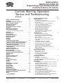
Controls, Start-Up, Operation,
Service and Troubleshooting
CONTENTS
Page
SAFETY CONSIDERATIONS . . . . . . . . . . . . . . . . . . . . .2,3
GENERAL . . . . . . . . . . . . . . . . . . . . . . . . . . . . . . . . . . . . . . .3,4
Conventions Used in this Manual . . . . . . . . . . . . . . . . 3
BASIC CONTROL USAGE . . . . . . . . . . . . . . . . . . . . . . 4-7
ComfortLink Controls . . . . . . . . . . . . . . . . . . . . . . . . . . . . 4
Scrolling Marquee. . . . . . . . . . . . . . . . . . . . . . . . . . . . . . . . 4
Accessory Navigator™ Display . . . . . . . . . . . . . . . . . . 4
Operation . . . . . . . . . . . . . . . . . . . . . . . . . . . . . . . . . . . . . . . . 5
System Pilot™ Interface. . . . . . . . . . . . . . . . . . . . . . . . . . 5
CCN Tables and Display. . . . . . . . . . . . . . . . . . . . . . . . . . 5
• GENERIC STATUS DISPLAY TABLE
START-UP . . . . . . . . . . . . . . . . . . . . . . . . . . . . . . . . . . . . . 7-32
Unit Preparation. . . . . . . . . . . . . . . . . . . . . . . . . . . . . . . . . . 7
Internal Wiring . . . . . . . . . . . . . . . . . . . . . . . . . . . . . . . . . . . 7
Accessory Installation . . . . . . . . . . . . . . . . . . . . . . . . . . . 7
Crankcase Heaters . . . . . . . . . . . . . . . . . . . . . . . . . . . . . . . 7
Evaporator Fan. . . . . . . . . . . . . . . . . . . . . . . . . . . . . . . . . . . 7
Controls. . . . . . . . . . . . . . . . . . . . . . . . . . . . . . . . . . . . . . . . . . 7
Gas Heat . . . . . . . . . . . . . . . . . . . . . . . . . . . . . . . . . . . . . . . . . 7
CONTROLS QUICK START . . . . . . . . . . . . . . . . . . . 32-35
Variable Air Volume Units Using Return Air
Sensor or Space Temperature Sensor. . . . . . . . . 32
Multi-Stage Constant Volume Units with
Mechanical Thermostat . . . . . . . . . . . . . . . . . . . . . . . 32
Multi-Stage Constant Volume Units with
Space Sensor . . . . . . . . . . . . . . . . . . . . . . . . . . . . . . . . . 33
Economizer Options . . . . . . . . . . . . . . . . . . . . . . . . . . . . 33
Indoor Air Quality Options . . . . . . . . . . . . . . . . . . . . . . 33
Exhaust Options . . . . . . . . . . . . . . . . . . . . . . . . . . . . . . . . 33
Set Clock on VFD (if installed). . . . . . . . . . . . . . . . . . . 34
Programming Operating Schedules . . . . . . . . . . . . . 34
SERVICE TEST . . . . . . . . . . . . . . . . . . . . . . . . . . . . . . . 35-38
General . . . . . . . . . . . . . . . . . . . . . . . . . . . . . . . . . . . . . . . . . 35
Service Test Mode Logic . . . . . . . . . . . . . . . . . . . . . . . . 35
Independent Outputs. . . . . . . . . . . . . . . . . . . . . . . . . . . . 35
Fans . . . . . . . . . . . . . . . . . . . . . . . . . . . . . . . . . . . . . . . . . . . . 35
Actuators . . . . . . . . . . . . . . . . . . . . . . . . . . . . . . . . . . . . . . . 35
Humidi-MiZer® System . . . . . . . . . . . . . . . . . . . . . . . . . . 37
Cooling . . . . . . . . . . . . . . . . . . . . . . . . . . . . . . . . . . . . . . . . . 37
Heating. . . . . . . . . . . . . . . . . . . . . . . . . . . . . . . . . . . . . . . . . . 38
THIRD PARTY CONTROL . . . . . . . . . . . . . . . . . . . . . 38-40
Thermostat. . . . . . . . . . . . . . . . . . . . . . . . . . . . . . . . . . . . . . 38
Alarm Output. . . . . . . . . . . . . . . . . . . . . . . . . . . . . . . . . . . . 38
Remote Switch . . . . . . . . . . . . . . . . . . . . . . . . . . . . . . . . . . 38
VFD Control . . . . . . . . . . . . . . . . . . . . . . . . . . . . . . . . . . . . . 38
Supply Air Reset . . . . . . . . . . . . . . . . . . . . . . . . . . . . . . . . 38
Demand Limit Control . . . . . . . . . . . . . . . . . . . . . . . . . . . 39
Economizer/Outdoor Air Damper Control . . . . . . . 39
CONTROLS OPERATION . . . . . . . . . . . . . . . . . . . . . 40-96
Modes. . . . . . . . . . . . . . . . . . . . . . . . . . . . . . . . . . . . . . . . . . . 40
• SYSTEM MODES
• HVAC MODES
Page
Unit Configuration Submenu . . . . . . . . . . . . . . . . . . . . 43
Cooling Control . . . . . . . . . . . . . . . . . . . . . . . . . . . . . . . . . 45
• SETTING UP THE SYSTEM
• MACHINE DEPENDENT CONFIGURATIONS
• SET POINTS
• SUPPLY AIR RESET CONFIGURATION
• COOLING CONFIGURATION
• COOL MODE SELECTION PROCESS
• COOL MODE DIAGNOSTIC HELP
• SUMZ COOLING ALGORITM
• DEMAND LIMIT CONTROL
• HEAD PRESSURE CONTROL
• ECONOMIZER INTEGRATION WITH
MECHANICAL COOLING
Heating Control . . . . . . . . . . . . . . . . . . . . . . . . . . . . . . . . . 58
• SETTING UP THE SYSTEM
• HEAT MODE SELECTION PROCESS
• TEMPERATURE DRIVEN HEAT MODE
EVALUATION
• HEAT MODE DIAGNOSTIC HELP
• TWO-STAGE GAS AND ELECTRIC HEAT
CONTROL
• HYDRONIC HEATING CONTROL
• STAGED GAS HEAT CONTROL
• MODULATING GAS HEAT CONTROL
• SCR ELECTRIC HEAT CONTROL
• CONTROL BOARD INFORMATION
• RELOCATE SAT FOR HEATING-LINKAGE
APPLICATIONS
• TEMPERING MODE
Static Pressure Control . . . . . . . . . . . . . . . . . . . . . . . . . 67
• OPERATION FOR VAV
• OPERATION FOR CV
• SETTING UP THE SYSTEM
• STATIC PRESSURE RESET
• RELATED POINTS
Fan Status Monitoring. . . . . . . . . . . . . . . . . . . . . . . . . . . 70
• GENERAL
• SETTING UP THE SYSTEM
• SUPPLY FAN STATUS MONITORING LOGIC
Dirty Filter Switch . . . . . . . . . . . . . . . . . . . . . . . . . . . . . . . 70
Economizer . . . . . . . . . . . . . . . . . . . . . . . . . . . . . . . . . . . . . 70
• ECONOMIZER FAULT DETECTION AND DIAGNOSTICS (FDD) CONTROL
• DIFFERENTIAL DRY BULB CUTOFF CONTROL
• ECONOMIZER SELF-TEST
• FAULT DETECTION DIAGNOSTIC CONFIGURATION POINTS
• SETTING UP THE SYSTEM
• ECONOMIZER OPERATION
• ECONOMIZER CHANGEOVER SELECT
• UNOCCUPIED ECONOMIZER FREE COOLING
• OUTDOOR AIR CFM CONTROL
• ECONOMIZER OPERATION CONFIGURATION
• ECONOMIZER DIAGNOSTIC HELP
Manufacturer reserves the right to discontinue, or change at any time, specifications or designs without notice and without incurring obligations.
Catalog No. 04-53480112-01
Printed in U.S.A.
Form 48/50P-6T
Pg 1
415
8-14
Replaces: 48/50P-5T
Page
Cleaning . . . . . . . . . . . . . . . . . . . . . . . . . . . . . . . . . . . . . . . 153
Lubrication . . . . . . . . . . . . . . . . . . . . . . . . . . . . . . . . . . . . . 154
Refrigerant Feed Components . . . . . . . . . . . . . . . . . 154
Thermostatic Expansion Valve (TXV) . . . . . . . . . . . 154
Refrigeration Circuits . . . . . . . . . . . . . . . . . . . . . . . . . . 154
Gas System Adjustment (48P Only) . . . . . . . . . . . . 174
Moisture/Liquid Indicator. . . . . . . . . . . . . . . . . . . . . . . 174
Filter Drier. . . . . . . . . . . . . . . . . . . . . . . . . . . . . . . . . . . . . . 175
Liquid Line Service Valves . . . . . . . . . . . . . . . . . . . . . 175
Protective Devices . . . . . . . . . . . . . . . . . . . . . . . . . . . . . 175
Temperature Relief Devices . . . . . . . . . . . . . . . . . . . . 175
Control Circuit, 115 V. . . . . . . . . . . . . . . . . . . . . . . . . . . 175
Control Circuit, 24 V . . . . . . . . . . . . . . . . . . . . . . . . . . . . 175
Gas Heat (48P Only) . . . . . . . . . . . . . . . . . . . . . . . . . . . . 175
Compressor Removal . . . . . . . . . . . . . . . . . . . . . . . . . . 176
Compressor Replacement. . . . . . . . . . . . . . . . . . . . . . 176
APPENDIX A — LOCAL DISPLAY TABLES. . 177-190
APPENDIX B — CCN TABLES . . . . . . . . . . . . . . 191-210
APPENDIX C — UNIT STAGING TABLES. . . . 211,212
APPENDIX D — VFD INFORMATION . . . . . . . . 213-222
APPENDIX E — MODE SELECTION
PROCESS . . . . . . . . . . . . . . . . . . . . . . . . . . . . . . . . 223,224
APPENDIX F — UPC OPEN CONTROLLER . . . . 225-235
APPENDIX G — OPTIONAL MOTORMASTER V
CONTROL. . . . . . . . . . . . . . . . . . . . . . . . . . . . . . . . . . . 236-242
INDEX . . . . . . . . . . . . . . . . . . . . . . . . . . . . . . . . . . . . . . . . . . 244
CONTROLS SET POINT AND
CONFIGURATION LOG . . . . . . . . . . . . . . . .CL-1 - CL-7
UNIT START-UP CHECKLIST . . . . . . . . . . . . . . . . . .CL-8
CONTENTS (cont)
Page
Building Pressure Control . . . . . . . . . . . . . . . . . . . . . . . 78
• BUILDING PRESSURE CONFIGURATION
• BUILDING PRESSURE CONTROL OPERATION
• CONFIGURING THE BUILDING PRESSURE
ACTUATORS TO COMMUNICATE VIA ACTUATOR
SERIAL NUMBER
• CONTROL ANGLE ALARM CONFIGURATION
Smoke Control Modes . . . . . . . . . . . . . . . . . . . . . . . . . . . 81
• FIRE SMOKE INPUTS
• AIRFLOW CONTROL DURING FIRE/SMOKE
MODES
• RELEVANT ITEMS
Indoor Air Quality Control . . . . . . . . . . . . . . . . . . . . . . . 81
• OPERATION
• SETTING UP THE SYSTEM
• PRE-OCCUPANCY PURGE
• OPTIONAL AIRFLOW STATION
Humidification. . . . . . . . . . . . . . . . . . . . . . . . . . . . . . . . . . . 85
• SETTING UP THE SYSTEM
• OPERATION
• CONFIGURING THE HUMIDIFIER ACTUATOR
Dehumidification and Reheat. . . . . . . . . . . . . . . . . . . . 86
• SETTING UP THE SYSTEM
• OPERATION
Humidi-MiZer® Adaptive Dehumidification
System . . . . . . . . . . . . . . . . . . . . . . . . . . . . . . . . . . . . . . . 88
• SET UP THE SYSTEM
• OPERATION
• HUMIDI-MIZER MODES
Temperature Compensated Start . . . . . . . . . . . . . . . . 89
• SETTING UP THE SYSTEM
• TEMPERATURE COMPENSATED START LOGIC
Carrier Comfort Network® (CCN). . . . . . . . . . . . . . . . . 90
Alert Limit Configuration . . . . . . . . . . . . . . . . . . . . . . . . 91
Sensor Trim Configuration . . . . . . . . . . . . . . . . . . . . . . 92
Discrete Switch Logic Configuration . . . . . . . . . . . . 93
Display Configuration . . . . . . . . . . . . . . . . . . . . . . . . . . . 94
VFD Configurations . . . . . . . . . . . . . . . . . . . . . . . . . . . . . 94
Remote Control Switch Input . . . . . . . . . . . . . . . . . . . . 96
Hot Gas Bypass . . . . . . . . . . . . . . . . . . . . . . . . . . . . . . . . . 96
Space Temperature Offset . . . . . . . . . . . . . . . . . . . . . . . 96
TIME CLOCK CONFIGURATION . . . . . . . . . . . . . . 97,98
TROUBLESHOOTING. . . . . . . . . . . . . . . . . . . . . . . . 98-124
Complete Unit Stoppage . . . . . . . . . . . . . . . . . . . . . . . . 98
Single Circuit Stoppage . . . . . . . . . . . . . . . . . . . . . . . . . 98
Service Analysis . . . . . . . . . . . . . . . . . . . . . . . . . . . . . . . . 98
Restart Procedure . . . . . . . . . . . . . . . . . . . . . . . . . . . . . . . 98
Humidi-MiZer® Troubleshooting . . . . . . . . . . . . . . . . . 98
Thermistor Troubleshooting . . . . . . . . . . . . . . . . . . . . . 99
Transducer Troubleshooting. . . . . . . . . . . . . . . . . . . . 101
Forcing Inputs and Outputs . . . . . . . . . . . . . . . . . . . . 101
Run Status Menu . . . . . . . . . . . . . . . . . . . . . . . . . . . . . . . 101
• AUTO VIEW OF RUN STATUS
• ECONOMIZER RUN STATUS
• COOLING INFORMATION
• VFD INFORMATION DISPLAY TABLE
• MODE TRIP HELPER
• CCN/LINKAGE DISPLAY TABLE
• COMPRESSOR RUN HOURS DISPLAY TABLE
• COMPRESSOR STARTS DISPLAY TABLE
• SOFTWARE VERSION NUMBERS DISPLAY TABLE
Alarms and Alerts . . . . . . . . . . . . . . . . . . . . . . . . . . . . . . 114
MAJOR SYSTEM COMPONENTS . . . . . . . . . . . 124-148
General. . . . . . . . . . . . . . . . . . . . . . . . . . . . . . . . . . . . . . . . . 124
Factory-Installed Components . . . . . . . . . . . . . . . . . 124
Accessory Control Components. . . . . . . . . . . . . . . . 145
SERVICE . . . . . . . . . . . . . . . . . . . . . . . . . . . . . . . . . . . 148-176
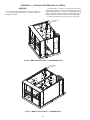
Service Access. . . . . . . . . . . . . . . . . . . . . . . . . . . . . . . . . 148
Adjustments. . . . . . . . . . . . . . . . . . . . . . . . . . . . . . . . . . . . 151
SAFETY CONSIDERATIONS
Installation and servicing of air-conditioning equipment can
be hazardous due to system pressure and electrical components. Only trained and qualified service personnel should
install, repair, or service air-conditioning equipment. Untrained
personnel can perform the basic maintenance functions of
replacing filters. Trained service personnel should perform all
other operations.
When working on air-conditioning equipment, observe precautions in the literature, tags and labels attached to the unit,
and other safety precautions that may apply. Follow all safety
codes. Wear safety glasses and work gloves. Use quenching
cloth for unbrazing operations. Have fire extinguishers available for all brazing operations.
WARNING
Before performing service or maintenance operation on
unit, turn off and lock off main power switch to unit.
Electrical shock can cause personal injury and death.
Shut off all power to this equipment during installation
and service. The unit may have an internal non-fused
disconnect or a field-installed disconnect.
CAUTION
This unit uses a microprocessor-based electronic control
system. Do not use jumpers or other tools to short out components or to bypass or otherwise depart from recommended procedures. Any short-to-ground of the control
board or accompanying wiring may destroy the electronic
modules or electrical components.
2
The 48/50P Series units provide ventilation, cooling, and
heating (when equipped) in variable air volume (VAV) and
constant volume (CV) applications.
WARNING
1. Improper installation, adjustment, alteration, service,
or maintenance can cause property damage, personal
injury, or loss of life. Refer to the User’s Information
Manual provided with this unit for more details.
2. Do not store or use gasoline or other flammable
vapors and liquids in the vicinity of this or any other
appliance.
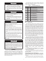
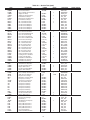
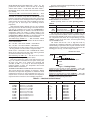
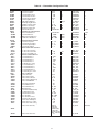
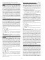
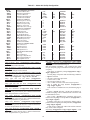
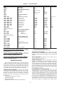
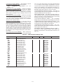
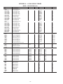
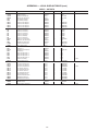
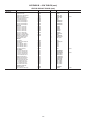
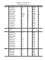
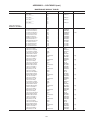
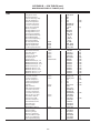
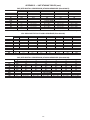
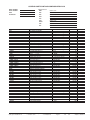
Table 1 — P Series Product Line
WARNING
What to do if you smell gas:
1. DO NOT try to light any appliance.
2. DO NOT touch any electrical switch, or use any
phone in your building.
3. IMMEDIATELY call your gas supplier from a neighbor’s phone. Follow the gas supplier’s instructions.
4. If you cannot reach your gas supplier call the fire
department.
WARNING
UNIT
SIZE
48P2
All
48P3
All
48P4
All
48P5
All
50P2
All
50P3
All
50P4
All
50P5
All
APPLICATION
Gas Heat, Vertical Supply/Return
CV ComfortLink Controls
Gas Heat, Vertical Supply/Return
VAV ComfortLink Controls
Gas Heat, Horizontal Supply/Return
CV ComfortLink Controls
Gas Heat, Horizontal Supply/Return
VAV ComfortLink Controls
Optional Electric Heat
Vertical Supply/Return
CV ComfortLink Controls
Optional Electric Heat
Vertical Supply/Return
VAV ComfortLink Controls
Optional Electric Heat
Horizontal Supply/Return
CV ComfortLink Controls
Optional Electric Heat
Horizontal Supply/Return
VAV ComfortLink Controls
LEGEND
CV — Constant Volume
VAV — Variable Air Volume
DO NOT USE TORCH to remove any component. System
contains oil and refrigerant under pressure.
To remove a component, wear protective gloves and goggles and proceed as follows:
a. Shut off electrical power to unit.
b. Recover refrigerant to relieve all pressure from system using both high-pressure and low pressure ports.
c. Traces of vapor should be displaced with nitrogen
and the work area should be well ventilated. Refrigerant in contact with an open flame produces toxic
gases.
d. Cut component connection tubing with tubing cutter
and remove component from unit. Use a pan to catch
any oil that may come out of the lines and as a gage
for how much oil to add to the system.
e. Carefully unsweat remaining tubing stubs when necessary. Oil can ignite when exposed to torch flame.
Failure to follow these procedures may result in personal
injury or death.
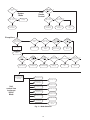
The 48/50P units contain the factory-installed ComfortLink
control system which provides full system management. The
main base board (MBB) stores hundreds of unit configuration
settings and 8 time of day schedules. The MBB also performs
self diagnostic tests at unit start-up, monitors the operation of
the unit, and provides alarms and alert information. The system
also contains other optional boards that are connected to the
MBB through the Local Equipment Network (LEN). Information on system operation and status are sent to the MBB processor by various sensors and optional board that are located at
the unit and in the conditioned space. Access to the unit controls for configuration, set point selection, schedule creation,
and service can be done through a unit-mounted scrolling marquee. Access can also be done through the Carrier Comfort
Network® using ComfortVIEW™ software, Network Service
Tool, or the accessory Navigator™ device.
The ComfortLink system controls all aspects of the rooftop.
It controls the supply-fan motor, compressors, and economizers
to maintain the proper temperature conditions. The controls
also cycle condenser fans to maintain suitable head pressure.
All VAV units are equipped with a VFD (variable frequency
drive) for supply duct pressure control. The ComfortLink
controls can directly control the speed of the VFD based on a
static pressure sensor input. In addition, the ComfortLink controls can adjust (but not control on CV and non-modulating
power exhaust units) the building pressure using multiple power exhaust fans controlled from damper position or from a
building pressure sensor. The control safeties are continuously
monitored to prevent the unit from operating under abnormal
conditions. Sensors include pressure transducers and
thermistors.
A scheduling function, programmed by the user, controls
the unit occupied/unoccupied schedule. Up to 8 different
schedules can be programmed.
The controls also allow the service person to operate a service test so that all the controlled components can be checked
for proper operation.
CAUTION
DO NOT re-use compressor oil or any oil that has been
exposed to the atmosphere. Dispose of oil per local codes
and regulations. DO NOT leave refrigerant system open to
air any longer than the actual time required to service the
equipment. Seal circuits being serviced and charge with
dry nitrogen to prevent oil contamination when timely
repairs cannot be completed. Failure to follow these procedures may result in damage to equipment.
GENERAL
This book contains Start-Up, Controls, Operation, Troubleshooting and Service information for the 48/50P Series
rooftop units. See Table 1. These units are equipped with
ComfortLink controls version 6.X or higher. Use this guide in
conjunction with the separate installation instructions packaged
with the unit. Refer to the Wiring Diagrams literature for more
detailed wiring information.
Conventions Used in This Manual — This manual
will use the following conventions for discussing configuration
points for the local display (scrolling marquee or Navigator™
accessory).
Parameter names will be written with the Mode name first,
then any submodes, then the parameter name, each separated
3
(CCN) building management system. The control provides
high-speed communications for remote monitoring. Multiple
48/50P Series units can be linked together (and to other ComfortLink controller equipped units) using a 3-wire communication bus.
The ComfortLink control system is easy to access through
the use of a unit-mounted display module. A computer is not
needed to perform unit start-up. Access to control menus is
simplified by the ability to quickly select from 11 menus. A
scrolling readout provides detailed explanations of control information. Only four, large, easy-to-use buttons are required to
maneuver through the entire controls menu. The display readout is designed to be visible even in bright sunlight.
For added service flexibility, an accessory hand-held
Navigator™ module is also available. This portable device has
an extended communication cable that can be plugged into the
unit’s communication network either at the main control box or
at the opposite end of the unit, at a remote modular plug. The
Navigator display provides the same menu structure, control
access and display data as is available at the unit-mounted
scrolling marquee display.
by an arrow symbol (o). Names will also be shown in bold
and italics. As an example, the IAQ Economizer Override Position which is located in the Configuration mode, Indoor Air
Quality Configuration sub-mode, and the Air Quality Set
Points sub-sub-mode, would be written as Configurationo
IAQoIAQ.SPoIQ.O.P.
This path name will show the user how to navigate through
the local display structure to reach the desired configuration.
The user would scroll through the modes and submodes using
the UP ARROW and DOWN ARROW keys. The arrow symbol in the path name represents pressing ENTER to move into
the next level of the menu structure.
When a value is included as part of the path name, it will be
shown at the end of the path name after an equals sign. If the
value represents a configuration setting, an explanation will be
shown in parenthesis after the value. As an example, ConfigurationoIAQoAQ.CFoIQ.A.C = 1 (IAQ Analog Input).
Pressing the ESCAPE and ENTER keys simultaneously
will scroll an expanded text description of the parameter name
across the display. The expanded description is shown in the
local display tables but will not be shown with the path names
in text.
The CCN (Carrier Comfort Network®) point names are also
cross-referenced in the local display tables (Appendix A) for
users configuring the unit with CCN software instead of the local display. The CCN tables are located in Appendix B of this
manual.
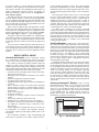
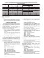
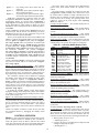
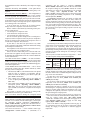
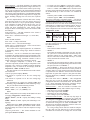
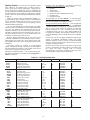
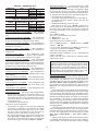
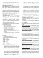
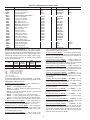
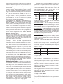
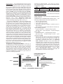
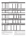
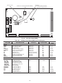
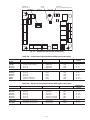
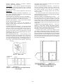
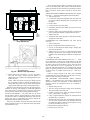
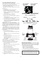
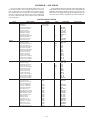
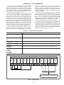
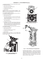
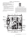
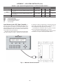
Scrolling Marquee — This device is the keypad interface used to access the control information, read sensor values,
and test the unit. The scrolling marquee is located in the main
control box and is standard on all units. The scrolling marquee
display is a 4-key, 4-character, 16-segment LED (light-emitting
diode) display module. The display also contains an Alarm Status LED. See Fig. 1. The display is easy to operate using
4 buttons and a group of 11 LEDs that indicate the following
menu structures: Run Status, Service Test, Temperatures, Pressures, Set points, Inputs, Outputs, Configuration, Timeclock,
Operating Modes, and Alarms.
Through the scrolling marquee, the user can access all of the
inputs and outputs to check on their values and status, configure operating parameters plus evaluate the current decision status for operating modes. Because the 48/50P Series units are
equipped with suction pressure and discharge pressure transducers, the scrolling marquee can also display refrigerant
circuit pressures typically obtained from service gages. The
control also includes an alarm history which can be accessed
from the display. In addition, through the scrolling marquee,
the user can access a built-in test routine that can be used at
start-up commissioning and to diagnose operational problems
with the unit.
BASIC CONTROL USAGE
ComfortLink Controls — The ComfortLink controls
are a comprehensive unit-management system. The control
system is easy to access, configure, diagnose and troubleshoot.
The controls are flexible, providing constant volume and
variable air volume cooling control sequences, and heating
control sequences for two-stage electric and gas systems, multiple-stage gas heating, and hydronic heat in both Occupied and
Unoccupied schedule modes. This control also manages:
• VAV duct pressure (through optional VFD), with configurable static pressure reset
• Building pressure through four different power exhaust
schemes
• Return fan applications using fan tracking
• Condenser fan head pressure control
• Dehumidification (with optional reheat) and humidifier
sequences
• Space ventilation control, in Occupied and Unoccupied
periods, using CO2 sensors or external signals, with ventilation defined by damper position or ventilation airflow
measurement
• Smoke control functions
• Occupancy schedules
• Occupancy or start/stop sequences based on third party
signals
• Alarm status and history and run time data
• Management of a complete unit service test sequence
• Economizer operation and Fault Detection and Diagnostics (FDD) per California Energy Commission (CEC)
Title 24-2013.
System diagnostics are enhanced by the use of sensors for
air temperatures, air pressures and refrigerant pressures.
Unit-mounted actuators provide digital feedback data to the
unit control.
The ComfortLink controller is fully communicating and
cable-ready for connection to the Carrier Comfort Network®
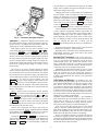
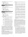
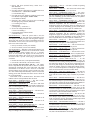
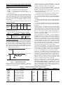
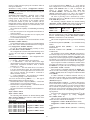
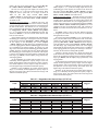
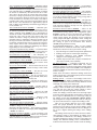
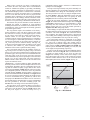
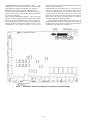
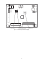
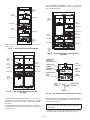
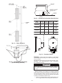
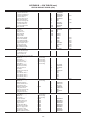
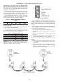
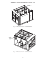
Accessory Navigator™ Display — The accessory
hand-held Navigator display can be used with the 48/50P
Series units. See Fig. 2. The Navigator display operates the
same way as the scrolling marquee device. The Navigator
display is plugged into the RJ-11 jack in the main control box
on the COMM board. The Navigator display can also be
plugged into the RJ-11 jack located on the unit corner post
located at the economizer end of the unit.
MODE
Run Status
Service Test
Temperature
Pressures
Setpoints
Inputs
Alarm Status
Outputs
Configuration
Time Clock
ESCAPE
ENTER
Operating Modes
Alarms
Fig. 1 — Scrolling Marquee
4
Co m
NA
T IM E
EWT
LW T
SETP
MO
fort
VIG
return the display to its default menu of rotating AUTO VIEW
display items. In addition, the password will need to be entered
again before changes can be made.
Li n k
ATO
R
12.
54. 58
44. 6 F
4 4 . 01 F
F
Changing item values or testing outputs is accomplished in
the same manner. Locate and display the desired item. If the
display is in rotating auto-view, press the ENTER key to stop
the display at the desired item. Press the ENTER key again so
that the item value flashes. Use the arrow keys to change the
value or state of an item and press the ENTER key to accept
it. Press the ESCAPE key and the item, value or units display
will resume. Repeat the process as required for other items.
DE
Run
Statu
s
Servi
ce Te
st
Temp
eratur
es
Pres
sures
Setpo
ints
Inputs
Al ar
m St
atu
s
Outpu
ts
Confi
gurat
ion
Time
Cloc
k
Opera
ting
Mode
Alarm
s
s
ENT
ESC
ER
If the user needs to force a variable, follow the same process
as when editing a configuration parameter. When using the
Navigator display, a forced variable will be displayed with a
blinking “f” following its value. For example, if supply fan requested (FAN.F) is forced, the display shows “YESf”, where
the “f” is blinking to signify a force on the point. Remove the
force by selecting the point that is forced with the
ENTER key and then pressing the arrow keys simultaneously.
Fig. 2 — Accessory Navigator Display
Operation — All units are shipped from the factory with
the scrolling marquee display, which is located in the main control box. See Fig. 1. In addition, the ComfortLink controls also
supports the use of the handheld Navigator™ display.
Both displays provide the user with an interface to the
ComfortLink control system. The displays have
and
arrow keys, an ESCAPE key and an ENTER key. These keys
are used to navigate through the different levels of the display
structure. The Navigator and the scrolling marquee operate in
the same manner, except that the Navigator display has multiple lines of display and the scrolling marquee has a single line.
All further discussions and examples in this document will be
based on the scrolling marquee display. See Table 2 for the
menu structure.
When using the scrolling marquee display, a forced variable
is displayed by a blinking “.” following its value.
Depending on the unit model, factory-installed options and
field-installed accessories, some of the items in the various
mode categories may not apply.
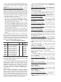
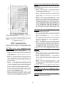
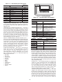
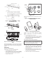
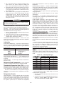
System Pilot™ Interface — The System Pilot inter-
face (33PILOT-01) is a component of the 3V™ system and can
serve as a user-interface and configuration tool for all Carrier
communicating devices. The System Pilot interface can be
used to install and commission a 3V zoning system, linkage
compatible air source, universal controller, and all other devices operating on the Carrier communicating network.
Additionally, the System Pilot interface can serve as a wallmounted temperature sensor for space temperature measurement. The occupant can use the System Pilot interface to
change set points. A security feature is provided to limit access
of features for unauthorized users. See Fig. 3 for System Pilot
interface details.
The four keys are used to navigate through the display
structure, which is organized in a tiered mode structure. See Table 2 for the first two levels of the mode structure. If the buttons
have not been used for a period, the display will default to the
AUTO VIEW display category as shown under the RUN STATUS category. To show the top-level display, press the
ESCAPE key until a blank display is shown. Then use the
and
arrow keys to scroll through the top-level categories. These are listed in Appendix A and will be indicated on
the scrolling marquee by the LED next to each mode listed on
the face of the display.
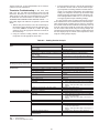
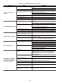
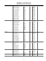
CCN Tables and Display — In addition to the unit-
mounted scrolling marquee display, the user can also access the
same information through the CCN tables by using the System
Pilot, Service Tool or other CCN programs. Details on the
CCN tables are summarized in Appendix B. The point names
used for the CCN tables and the scrolling marquee tables may
be different and more items are displayed in the CCN tables.
As a reference, the CCN point names are included in the scrolling marquee tables and the scrolling marquee acronyms are included in the CCN tables in Appendix B.
GENERIC STATUS DISPLAY TABLE — The GENERICS
points table allows the service/installer the ability to create a
custom table in which up to 20 points from the 5 CCN
categories (Status, Config/Service-Config, Set Point, Maintenance, and Occupancy) may be collected and displayed.
In the Service-Config table section, there is a table named
“generics.” This table contains placeholders for up to 20 CCN
point names and allows the user to decide which points are displayed in the GENERIC points table. Each one of these placeholders allows the input of an 8-character ASCII string.
Using a CCN method of interface, go into the Edit mode for
the Service-Config table “generics” and enter the CCN name for
each point to be displayed in the custom points table in the order
they will be displayed. When done entering point names, download the table to the rooftop unit control.
When a specific mode or sub-mode is located, push the
ENTER key to enter the mode. Depending on the mode, there
may be additional tiers. Continue to use the
and
keys
and the ENTER keys until the desired display item is found.
At any time, the user can move back a mode level by pressing
the ESCAPE key. Once an item has been selected the display
will flash showing the item, followed by the item value and
then followed by the item units (if any).
Items in the Configuration and Service Test modes are
password protected. The display will flash PASS and WORD
when required. Use the ENTER and arrow keys to enter the
four digits of the password. The default password is 1111.
Pressing the ESCAPE and ENTER keys simultaneously
will scroll an expanded text description across the display indicating the full meaning of each display point. Pressing the
ESCAPE and ENTER keys when the display is blank will
5
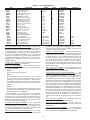
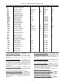
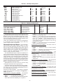
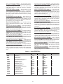
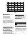
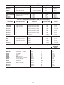
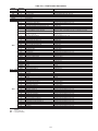
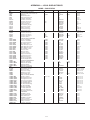
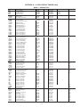
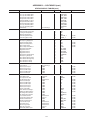
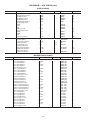
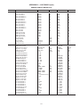
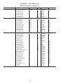
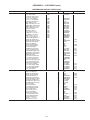
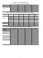
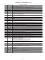
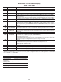
Table 2 — Scrolling Marquee Menu Display Structure
RUN
STATUS
Auto View of
Run Status
(VIEW)
SERVICE
TEST
Service Test Mode
(TEST)
Econ
Run Status
(ECON)
Software
Command
Disable
(STOP)
p
p
Cooling
Information
(COOL)
p
p
p
Soft Stop
Request
(S.STP)
p
TEMPERATURES
PRESSURES
SETPOINTS
INPUTS
OUTPUTS
CONFIGURATION
Air
Temperatures
(AIR.T)
Air Pressures
(AIR.P)
Occupied Heat
Setpoint
(OHSP)
General Inputs
(GEN.I)
Fans
(FANS)
Unit
Configuration
(UNIT)
Compressor
Feedback
(FD.BK)
Cooling
(COOL)
p
Refrigerant
Temperatures
(REF.T)
p
Refrigerant
Pressures
(REF.P)
p
Occupied Cool
Setpoint
(OCSP)
Unoccupied
Heat Setpoint
(UHSP)
Unoccupied
Cool Setpoint
(UCSP)
Mode
Trip Helper
(TRIP)
Test Independent
Outputs
(INDP)
Heat - Cool
Setpoint
(GAP)
p
CCN
Linkage
(LINK)
p
Compressor
Run Hours
(HRS)
p
Compressor
Starts
(STRT)
p
Software
Version
Numbers
(VERS)
p
Test Fans
(FANS)
p
Calibrate Test
Actuators
(ACT.C)
p
Test
Humidimizer
(HMZR)
p
Test Cooling
(COOL)
p
Test Heating
(HEAT)
Thermostat
Inputs
(STAT)
p
p
Supply Fan
Request
(FAN.F)
p
p
p
VFD
Information
(VFDS)
p
p
Fire-Smoke
Modes
(FIRE)
p
p
Relative
Humidity
(REL.H)
p
p
VAV Occ
Cool On
(V.C.ON)
Air Quality
Sensors
(AIR.Q)
p
p
VAV Occ
Cool Off
(V.C.OF)
p
Supply Air
Setpoint
(SASP)
p
CFM Sensors
(CFM)
p
Reset Inputs
(RSET)
p
4-20 Milliamp
Inputs
(4-20)
p
p
Heating
(HEAT)
Actuators
(ACTU)
p
General
Outputs
(GEN.O)
p
Cooling
Configuration
(COOL)
p
Evap/Discharge
Temp. Reset
(EDT.R)
p
Heating
Configuration
(HEAT)
p
Supply Static
Press. Config.
(SP)
p
Economizer
Configuration
(ECON)
p
Building Press.
Configs
(BP)
p
Cool/Heat
Setpt. Offsets
(D.L.V.T)
p
Supply Air
Setpoint Hi
(SA.HI)
Demand Limit
Config.
(DMD.L)
Supply Air
Setpoint Lo
(SA.LO)
Indoor Air
Quality Cfg.
(IAQ)
Heating Supply
Air Setpoint
(SA.HT)
Humidity
Configuration
(HUMD)
Tempering
Purge SASP
(T.PRG)
Dehumidification
Config.
(DEHU)
Tempering in
Cool SASP
(T.CL)
CCN
Configuration
(CCN)
Tempering in
Vent Occ SASP
(T.V.OC)
Alert Limit
Config.
(ALLM)
Tempering in
Vent Unocc.
SASP
(T.V.UN)
Sensor Trim
Config.
(TRIM)
p
p
p
p
p
p
p
p
p
p
p
p
p
Switch
Logic
(SW.LG)
p
Display
Configuration
(DISP)
p
Supply Fan
VFD Config.
(S.VFD)
p
Exhaust Fan
VFD Config.
(E.VFD)
6
TIME
CLOCK
Time of Day
(TIME)
p
OPERATING
MODES
System
Mode
(SYS.M)
Month, Date,
Day and Year
(DATE)
HVAC Mode
(HVAC)
p
Local Time
Schedule
(SCH.L)
p
Local
Holiday
Schedules
(HOL.L)
p
Daylight
Savings
Time
(DAY.S)
p
p
Control Type
(CTRL)
p
Mode
Controlling
Unit
(MODE)
ALARMS
Currently
Active
Alarms
(CURR)
p
Reset All
Current
Alarms
(R.CUR)
p
Alarm
History
(HIST)
Crankcase Heaters — Crankcase heaters are energized
as long as there is power to the unit, except when the compressors are running.
IMPORTANT: The computer system software
(ComfortVIEW™, Service Tool, etc.) that is used to
interact with CCN controls always saves a template of
items it considers as static (e.g., limits, units, forcibility, 24-character text strings, and point names) after
the software uploads the tables from a control. Thereafter, the software is only concerned with run time
data like value and hardware/force status. With this in
mind, it is important that anytime a change is made to
the Service-Config table “generics” (which in turn
changes the points contained in the GENERIC point
table), that a complete new upload be performed. This
requires that any previous table database be
completely removed first. Failure to do this will not
allow the user to display the new points that have been
created and the software will have a different table
database than the unit control.
IMPORTANT: Unit power must be on for 24 hours
prior to start-up of compressors. Otherwise damage to
compressors may result.
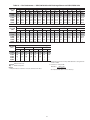
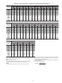
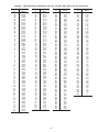
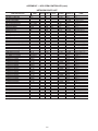
Evaporator Fan — Fan belt and fixed pulleys are factory-
installed. See Tables 3-24 for fan performance. Remove tape
from fan pulley, and be sure that fans rotate in the proper
direction. Static pressure drop is shown in Table 25. See
Tables 26-28 for motor limitations.
FIELD-SUPPLIED FAN DRIVES — Supply fan and power
exhaust fan drives are fixed-pitch, non-adjustable selections, for
maximum reliability and long belt life. If the factory drive sets
must be changed to obtain other fan speeds, consult the nearest
Browning Manufacturing Co. sales office with the required new
wheel speed and the data from Physical Data and Supply Fan
Drive Data tables (center distances, motor and fan shaft diameters, motor horsepower) in Installation Instructions for a
modified drive set selection. For minor speed changes, the fan
sheave size should be changed. (Do not reduce the size of the
motor sheave; this will result in reduced belt horsepower ratings
and reduced belt life.) See page 151 for belt installation
procedure.
Controls — Use the following steps for the controls:
IMPORTANT: The unit is shipped with the unit control
disabled. To enable the control, set Local Machine Disable
(Service TestoSTOP) to No.
MODIFY/
SELECT
NAVIGATE/
EXIT
SCROLL
+
1. Set any control configurations that are required (fieldinstalled accessories, etc.). The unit is factory configured
for all appropriate factory-installed options.
2. Enter unit set points. The unit is shipped with the set point
default values. If a different set point is required, use the
scrolling marquee, Navigator™ display, or CCN interface
to change the configuration values.
3. If the internal time schedules are going to be used, configure the Occupancy schedule.
4. Verify that the control time periods programmed meet
current requirements.
5. Use Service Test mode to verify operation of all major
components.
6. If the unit is a VAV unit make sure to configure the static
pressure set point. To check out the VFD, use the VFD instructions shipped with the unit.
PAGE
-
Fig. 3 — System Pilot User Interface
START-UP
IMPORTANT: Do not attempt to start unit, even
momentarily, until all items on the Start-Up Checklist
(at the back of this book) and the following steps have
been completed.
Gas Heat — Verify gas pressure before turning on gas heat
as follows:
1. Turn off field-supplied manual gas stop, located external
to the unit.
2. Connect pressure gages to supply gas tap, located at fieldsupplied manual shutoff valves.
3. Connect pressure gages to manifold pressure tap on unit
gas valve.
4. Supply gas pressure must not exceed 13.5 in. wg. Check
pressure at field-supplied shut-off valve.
5. Turn on manual gas stop and initiate a heating demand.
Jumper R to W1 in the control box to initiate heat.
6. Use the Service Test procedure to verify all heat stages of
operation.
7. After the unit has run for several minutes, verify that
incoming pressure is 5.0 in. wg or greater and that the
manifold pressure is 3.5 in wg. If manifold pressure must
be adjusted refer to Gas Valve Adjustment section on
page 174.
IMPORTANT: The unit is shipped with the unit control
disabled. To enable the control, set Local Machine Disable
(Service TestoSTOP) to No.
Unit Preparation — Check that unit has been installed in
accordance with the installation instructions and applicable
codes. Make sure that the economizer hood has been installed
and that the outdoor filters are properly installed.
Internal Wiring — Ensure that all electrical connections
in the control box are tightened as required. If the unit has
staged gas, modulating gas, or SCR (silicon controlled rectifier) electric heat make sure that the LAT (leaving air temperature) sensors have been routed to the supply ducts as required.
Accessory Installation — Check to make sure that all
accessories including space thermostats and sensors have been
installed and wired as required by the instructions and unit
wiring diagrams.
7
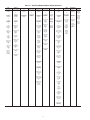
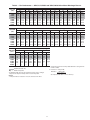
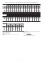
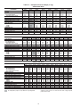
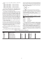
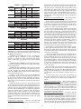
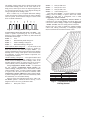
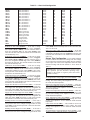
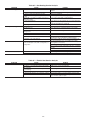
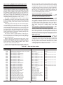
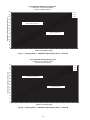
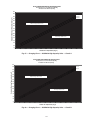
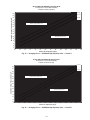
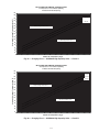
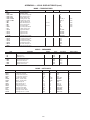
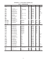
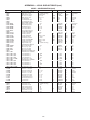
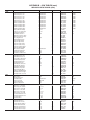
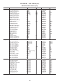
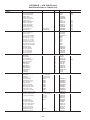
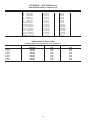
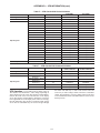
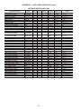
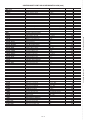
Table 3 — Fan Performance — 48P2,P3,P4,P5030 and 50P2,P3030 Units without Discharge Plenum*
AVAILABLE EXTERNAL STATIC PRESSURE (in. wg)
AIRFLOW
(cfm)
6,000
7,500
9,000
10,500
12,000
13,500
15,000
0.2
0.4
0.6
0.8
1.0
1.2
1.4
1.6
Rpm
Bhp
Rpm
Bhp
Rpm
Bhp
Rpm
Bhp
Rpm
Bhp
Rpm
Bhp
Rpm
Bhp
Rpm
Bhp
222
248
278
311
344
379
415
0.59
0.94
1.46
2.16
3.08
4.25
5.69
284
300
323
349
378
410
442
0.91
1.28
1.80
2.52
3.44
4.62
6.06
339
350
366
387
412
440
470
1.27
1.68
2.22
2.95
3.89
5.07
6.52
388
395
407
424
445
469
496
1.66
2.11
2.69
3.43
4.39
5.58
7.04
430
437
446
459
477
498
523
2.07
2.57
3.19
3.96
4.93
6.13
7.61
469
475
483
493
508
527
549
2.50
3.05
3.71
4.51
5.51
6.73
8.22
504
511
517
526
539
555
575
2.93
3.54
4.25
5.10
6.12
7.36
8.87
536
544
550
558
569
583
601
3.38
4.05
4.81
5.70
6.75
8.02
9.55
AVAILABLE EXTERNAL STATIC PRESSURE (in. wg)
AIRFLOW
(cfm)
6,000
7,500
9,000
10,500
12,000
13,500
15,000
1.8
2.0
2.2
2.4
2.6
2.8
3.0
3.2
Rpm
Bhp
Rpm
Bhp
Rpm
Bhp
Rpm
Bhp
Rpm
Bhp
Rpm
Bhp
Rpm
Bhp
Rpm
Bhp
567
575
581
588
598
610
626
3.84
4.57
5.38
6.31
7.41
8.71
10.25
595
604
611
617
625
637
651
4.30
5.10
5.97
6.95
8.08
9.41
10.98
622
632
639
645
652
662
675
4.78
5.63
6.56
7.59
8.77
10.14
11.74
647
658
665
672
679
687
699
5.26
6.18
7.16
8.25
9.47
10.88
12.51
671
683
691
697
704
712
723
5.75
6.73
7.78
8.92
10.19
11.63
13.30
695
707
715
722
728
736
746
6.25
7.29
8.40
9.59
10.91
12.40
14.10
717
730
739
746
752
759
768
6.76
7.86
9.03
10.28
11.65
13.18
14.92
738
752
761
769
775
782
790
7.27
8.43
9.66
10.97
12.39
13.98
15.75
AVAILABLE EXTERNAL STATIC PRESSURE (in. wg)
AIRFLOW
(cfm)
6,000
7,500
9,000
10,500
12,000
13,500
15,000
3.4
3.6
3.8
4.0
Rpm
Bhp
Rpm
Bhp
Rpm
Bhp
Rpm
Bhp
759
773
783
791
797
804
812
7.79
9.01
10.30
11.67
13.15
14.77
16.59
779
794
805
812
819
825
833
8.32
9.60
10.95
12.38
13.91
15.59
17.45
799
814
825
833
840
846
853
8.85
10.20
11.60
13.09
14.68
16.41
18.31
817
833
845
854
860
867
874
9.39
10.80
12.26
13.81
15.45
17.23
19.19
2. See Component Pressure Drop data table before using Fan Performance tables.
3. Conversion — Bhp to kW:
LEGEND
48/50P3,P5 units only.
Bhp — Brake Horsepower
Kilowatts =
*If calculating static pressure for a 48 Series unit, be sure to add gas
heat pressure drop from Component Pressure Drop table.
NOTES:
1. Fan performance is based on wet coils and clean 2-in. filters.
Bhp x .746
Motor efficiency
See Physical Data table for motor efficiency.
8
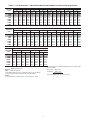
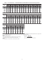
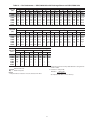
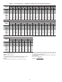
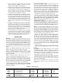
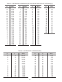
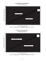
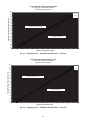
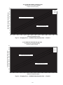
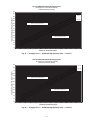
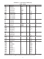
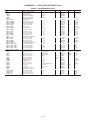
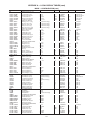
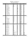
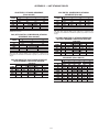
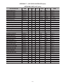
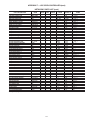
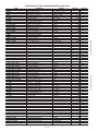
Table 4 — Fan Performance — 48P2,P3,P4,P5035 and 50P2,P3035 Units without Discharge Plenum*
AVAILABLE EXTERNAL STATIC PRESSURE (in. wg)
AIRFLOW
(cfm)
0.2
0.4
0.6
0.8
1.0
1.2
1.4
1.6
Rpm
Bhp
Rpm
Bhp
Rpm
Bhp
Rpm
Bhp
Rpm
Bhp
Rpm
Bhp
Rpm
Bhp
Rpm
Bhp
246
266
310
357
406
430
0.84
1.14
1.98
3.20
4.87
5.89
301
315
350
390
435
458
1.19
1.50
2.36
3.60
5.28
6.31
352
362
389
424
463
485
1.58
1.92
2.80
4.06
5.76
6.80
398
406
427
457
492
511
2.01
2.37
3.30
4.58
6.30
7.35
440
447
464
489
520
538
2.46
2.85
3.83
5.15
6.89
7.95
479
484
499
520
548
564
2.93
3.35
4.38
5.74
7.52
8.59
514
519
532
551
576
590
3.40
3.87
4.96
6.36
8.18
9.26
547
552
564
580
603
616
3.90
4.39
5.55
7.01
8.86
9.96
7,000
8,000
10,000
12,000
14,000
15,000
AVAILABLE EXTERNAL STATIC PRESSURE (in. wg)
AIRFLOW
(cfm)
7,000
8,000
10,000
12,000
14,000
15,000
1.8
2.0
2.2
2.4
2.6
2.8
3.0
3.2
Rpm
Bhp
Rpm
Bhp
Rpm
Bhp
Rpm
Bhp
Rpm
Bhp
Rpm
Bhp
Rpm
Bhp
Rpm
Bhp
577
583
594
609
629
641
4.40
4.94
6.16
7.67
9.57
10.69
606
612
623
636
655
666
4.91
5.49
6.79
8.36
10.30
11.44
633
640
651
663
680
690
5.43
6.05
7.42
9.05
11.04
12.20
659
666
677
689
704
714
5.95
6.62
8.07
9.77
11.81
12.99
684
691
703
714
728
737
6.49
7.19
8.73
10.49
12.59
13.79
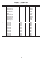
707
715
727
738
751
760
7.03
7.78
9.39
11.22
13.38
14.61
730
738
751
762
774
782
7.58
8.37
10.06
11.97
14.18
15.44
752
760
774
785
796
804
8.14
8.97
10.74
12.72
14.99
16.28
AVAILABLE EXTERNAL STATIC PRESSURE (in. wg)
AIRFLOW
(cfm)
7,000
8,000
10,000
12,000
14,000
15,000
3.4
3.6
3.8
4.0
Rpm
Bhp
Rpm
Bhp
Rpm
Bhp
Rpm
Bhp
773
782
796
807
818
825
8.70
9.57
11.42
13.48
15.82
17.13
793
802
817
828
840
846
9.27
10.18
12.11
14.25
16.66
18.00
813
823
838
849
860
866
9.85
10.80
12.81
15.02
17.50
18.87
832
842
858
869
880
886
10.43
11.43
13.52
15.80
18.35
19.76
2. See Component Pressure Drop data table before using Fan Performance tables.
3. Conversion — Bhp to kW:
LEGEND
48/50P3,P5 units only.
Bhp — Brake Horsepower
Kilowatts =
*If calculating static pressure for a 48 Series unit, be sure to add gas
heat pressure drop from Component Pressure Drop table.
NOTES:
1. Fan performance is based on wet coils and clean 2-in. filters.
Bhp x .746
Motor efficiency
See Physical Data table for motor efficiency.
9
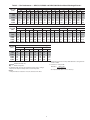
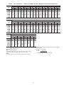
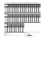
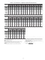
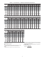
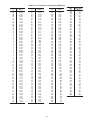
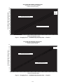
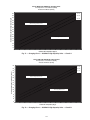
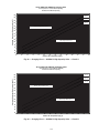
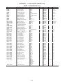
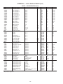
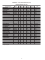
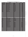
Table 5 — Fan Performance — 48P2,P3,P4,P5040 and 50P2,P3040 Units without Discharge Plenum*
AVAILABLE EXTERNAL STATIC PRESSURE (in. wg)
AIRFLOW
(cfm)
8,000
10,000
12,000
14,000
16,000
18,000
20,000
0.2
0.4
0.6
0.8
1.0
1.2
1.4
1.6
Rpm
Bhp
Rpm
Bhp
Rpm
Bhp
Rpm
Bhp
Rpm
Bhp
Rpm
Bhp
Rpm
Bhp
Rpm
Bhp
252
290
330
372
415
459
503
0.98
1.67
2.65
3.96
5.67
7.84
10.51
303
333
369
407
447
488
530
1.33
2.11
3.18
4.61
6.44
8.72
11.51
350
373
404
439
476
515
555
1.72
2.55
3.70
5.22
7.15
9.55
12.46
394
412
438
469
504
541
579
2.14
3.01
4.23
5.83
7.85
10.34
13.36
434
448
470
498
530
565
602
2.58
3.51
4.78
6.44
8.54
11.12
14.24
472
483
501
526
556
589
624
3.06
4.03
5.35
7.07
9.24
11.91
15.11
507
517
532
554
581
612
645
3.55
4.58
5.94
7.72
9.95
12.69
15.98
540
549
562
581
605
634
666
4.07
5.16
6.56
8.38
10.67
13.47
16.84
AVAILABLE EXTERNAL STATIC PRESSURE (in. wg)
AIRFLOW
(cfm)
8,000
10,000
12,000
14,000
16,000
18,000
20,000
1.8
2.0
2.2
2.4
2.6
2.8
3.0
3.2
Rpm
Bhp
Rpm
Bhp
Rpm
Bhp
Rpm
Bhp
Rpm
Bhp
Rpm
Bhp
Rpm
Bhp
Rpm
Bhp
571
579
590
607
629
656
687
4.60
5.75
7.21
9.07
11.41
14.28
17.71
600
608
618
633
653
678
707
5.14
6.36
7.87
9.78
12.16
15.09
18.60
628
636
645
658
676
700
727
5.70
6.98
8.55
10.51
12.94
15.91
19.48
654
662
671
683
699
721
747
6.27
7.62
9.25
11.25
13.73
16.76
20.38
679
688
696
707
722
742
766
6.85
8.28
9.96
12.02
14.54
17.62
21.30
703
712
720
730
744
762
785
7.44
8.94
10.69
12.80
15.37
18.49
22.22
726
736
744
753
766
783
804
8.04
9.62
11.43
13.60
16.22
19.39
23.17
748
758
766
775
787
803
—
8.65
10.30
12.19
14.41
17.08
20.29
—
AVAILABLE EXTERNAL STATIC PRESSURE (in. wg)
AIRFLOW
(cfm)
8,000
10,000
12,000
14,000
16,000
18,000
20,000
3.4
3.6
3.8
4.0
Rpm
Bhp
Rpm
Bhp
Rpm
Bhp
Rpm
Bhp
770
780
789
797
808
823
—
9.27
11.00
12.96
15.24
17.95
21.21
—
791
802
810
818
828
842
—
9.90
11.71
13.73
16.07
18.85
22.15
—
811
822
831
839
849
862
—
10.54
12.43
14.52
16.93
19.75
23.11
—
830
842
851
859
868
—
—
11.18
13.15
15.32
17.79
20.67
—
—
2. See Component Pressure Drop data table before using Fan Performance tables.
3. Conversion — Bhp to kW:
LEGEND
48/50P3,P5 units only.
Bhp — Brake Horsepower
Kilowatts =
*If calculating static pressure for a 48 Series unit, be sure to add gas
heat pressure drop from Component Pressure Drop table.
NOTES:
1. Fan performance is based on wet coils and clean 2-in. filters.
Bhp x .746
Motor efficiency
See Physical Data table for motor efficiency.
10
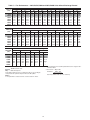
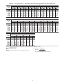
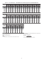
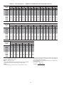
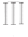
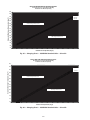
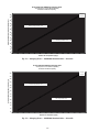
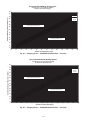
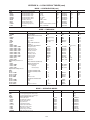
Table 6 — Fan Performance — 48P2,P3,P4,P5050 and 50P2,P3050 Units without Discharge Plenum*
AVAILABLE EXTERNAL STATIC PRESSURE (in. wg)
AIRFLOW
(cfm)
9,000
10,000
12,000
14,000
16,000
18,000
20,000
0.2
0.4
0.6
0.8
1.0
1.2
1.4
1.6
Rpm
Bhp
Rpm
Bhp
Rpm
Bhp
Rpm
Bhp
Rpm
Bhp
Rpm
Bhp
Rpm
Bhp
Rpm
Bhp
276
296
339
382
427
473
519
1.34
1.74
2.76
4.15
5.96
8.26
11.10
323
339
376
416
458
501
545
1.73
2.17
3.29
4.79
6.71
9.12
12.06
366
379
411
448
487
527
570
2.15
2.62
3.81
5.40
7.42
9.93
12.99
407
418
445
478
514
552
593
2.60
3.09
4.35
6.01
8.11
10.72
13.88
445
454
477
506
540
576
615
3.08
3.59
4.91
6.63
8.81
11.50
14.76
482
489
509
535
565
600
637
3.58
4.12
5.49
7.26
9.52
12.29
15.63
516
522
539
562
590
623
658
4.11
4.68
6.09
7.92
10.23
13.08
16.50
549
554
568
589
615
645
679
4.66
5.26
6.71
8.60
10.97
13.88
17.38
AVAILABLE EXTERNAL STATIC PRESSURE (in. wg)
AIRFLOW
(cfm)
9,000
10,000
12,000
14,000
16,000
18,000
20,000
1.8
2.0
2.2
2.4
2.6
2.8
3.0
3.2
Rpm
Bhp
Rpm
Bhp
Rpm
Bhp
Rpm
Bhp
Rpm
Bhp
Rpm
Bhp
Rpm
Bhp
Rpm
Bhp
579
584
597
615
639
667
699
5.23
5.85
7.36
9.29
11.71
14.69
18.25
608
613
625
641
663
689
719
5.81
6.47
8.03
10.01
12.48
15.51
19.14
636
641
651
666
686
711
739
6.41
7.10
8.72
10.74
13.27
16.35
20.04
662
667
677
690
709
732
759
7.02
7.74
9.42
11.50
14.07
17.20
20.95
687
692
702
714
731
753
778
7.64
8.40
10.14
12.27
14.89
18.07
21.88
712
717
726
738
753
773
797
8.27
9.07
10.88
13.06
15.73
18.96
22.82
735
740
750
760
775
793
816
8.91
9.75
11.63
13.87
16.58
19.86
23.77
757
763
772
783
796
813
—
9.57
10.44
12.39
14.69
17.45
20.78
—
AVAILABLE EXTERNAL STATIC PRESSURE (in. wg)
AIRFLOW
(cfm)
9,000
10,000
12,000
14,000
16,000
18,000
20,000
3.4
3.6
3.8
4.0
Rpm
Bhp
Rpm
Bhp
Rpm
Bhp
Rpm
Bhp
779
785
794
804
817
833
—
10.23
11.14
13.16
15.52
18.34
21.71
—
800
806
816
825
837
853
—
10.90
11.85
13.94
16.37
19.24
22.66
—
821
826
836
846
857
872
—
11.58
12.57
14.73
17.22
20.15
23.62
—
840
846
857
866
877
—
—
12.27
13.30
15.54
18.10
21.08
—
—
2. See Component Pressure Drop data table before using Fan Performance tables.
3. Conversion — Bhp to kW:
LEGEND
48/50P3,P5 units only.
Bhp — Brake Horsepower
Kilowatts =
*If calculating static pressure for a 48 Series unit, be sure to add gas
heat pressure drop from Component Pressure Drop table.
NOTES:
1. Fan performance is based on wet coils and clean 2-in. filters.
Bhp x .746
Motor efficiency
See Physical Data table for motor efficiency.
11
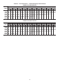
Table 7 — Fan Performance — 48P2,P3,P4,P5055 and 50P2,P3055 Units without Discharge Plenum*
AVAILABLE EXTERNAL STATIC PRESSURE (in. wg)
AIRFLOW
(cfm)
10,000
12,500
15,000
17,500
20,000
22,500
25,000
0.2
0.4
0.6
0.8
1.0
1.2
1.4
1.6
Rpm
Bhp
Rpm
Bhp
Rpm
Bhp
Rpm
Bhp
Rpm
Bhp
Rpm
Bhp
Rpm
Bhp
Rpm
Bhp
207
235
265
295
327
359
392
1.04
1.69
2.59
3.78
5.31
7.23
9.59
253
276
302
331
360
390
421
1.50
2.23
3.23
4.52
6.15
8.16
10.60
295
312
335
361
388
417
447
2.03
2.78
3.85
5.24
6.98
9.09
11.62
334
346
365
389
414
442
470
2.66
3.40
4.51
5.97
7.79
10.00
12.64
371
379
394
415
439
465
492
3.41
4.10
5.20
6.71
8.60
10.90
13.64
405
410
422
440
462
487
513
4.26
4.88
5.96
7.48
9.43
11.81
14.63
438
440
449
465
485
508
533
5.20
5.75
6.78
8.30
10.28
12.72
15.62
468
469
476
489
507
528
552
6.20
6.70
7.67
9.17
11.17
13.65
16.62
AVAILABLE EXTERNAL STATIC PRESSURE (in. wg)
AIRFLOW
(cfm)
10,000
12,500
15,000
17,500
20,000
22,500
25,000
1.8
2.0
2.2
2.4
2.6
2.8
3.0
3.2
Rpm
Bhp
Rpm
Bhp
Rpm
Bhp
Rpm
Bhp
Rpm
Bhp
Rpm
Bhp
Rpm
Bhp
Rpm
Bhp
497
497
501
512
528
548
571
7.27
7.73
8.63
10.09
12.09
14.60
17.63
523
523
526
535
549
567
589
8.39
8.83
9.67
11.07
13.06
15.59
18.66
549
549
550
557
570
587
607
9.55
10.00
10.77
12.11
14.07
16.61
19.71
573
573
574
579
590
605
624
10.75
11.22
11.94
13.21
15.12
17.66
20.78
596
597
597
601
610
624
642
11.98
12.49
13.17
14.38
16.24
18.75
21.89
618
619
619
622
630
642
659
13.23
13.81
14.46
15.60
17.40
19.88
23.02
639
641
641
643
649
660
676
14.51
15.16
15.80
16.88
18.62
21.06
24.19
659
662
662
663
668
678
692
15.81
16.55
17.19
18.21
19.89
22.28
25.39
AVAILABLE EXTERNAL STATIC PRESSURE (in. wg)
AIRFLOW
(cfm)
10,000
12,500
15,000
17,500
20,000
22,500
25,000
3.4
3.6
3.8
4.0
Rpm
Bhp
Rpm
Bhp
Rpm
Bhp
Rpm
Bhp
679
682
682
683
687
696
709
17.13
17.98
18.63
19.60
21.20
23.55
26.62
697
702
702
702
706
713
725
18.46
19.43
20.10
21.04
22.57
24.86
27.91
715
721
721
721
724
731
741
19.81
20.90
21.62
22.53
24.00
26.22
29.22
733
739
740
740
742
748
—
21.17
22.40
23.17
24.06
25.46
27.62
—
2. See Component Pressure Drop data table before using Fan Performance tables.
3. Conversion — Bhp to kW:
LEGEND
48/50P3,P5 units only.
Bhp — Brake Horsepower
Kilowatts =
*If calculating static pressure for a 48 Series unit, be sure to add gas
heat pressure drop from Component Pressure Drop table.
NOTES:
1. Fan performance is based on wet coils and clean 2-in. filters.
Bhp x .746
Motor efficiency
See Physical Data table for motor efficiency.
12
Table 8 — Fan Performance — 48P2,P3,P4,P5060 and 50P2,P3060 Units without Discharge Plenum*
AVAILABLE EXTERNAL STATIC PRESSURE (in. wg)
AIRFLOW
(cfm)
12,000
15,000
18,000
21,000
24,000
27,000
30,000
0.2
0.4
0.6
0.8
1.0
1.2
1.4
1.6
Rpm
Bhp
Rpm
Bhp
Rpm
Bhp
Rpm
Bhp
Rpm
Bhp
Rpm
Bhp
Rpm
Bhp
Rpm
Bhp
234
271
308
348
390
433
476
1.54
2.65
4.22
6.36
9.19
12.80
17.29
276
309
344
380
417
456
497
2.03
3.27
5.00
7.29
10.24
13.93
18.50
312
341
374
408
444
481
519
2.57
3.88
5.73
8.18
11.29
15.14
19.82
348
370
400
434
469
504
541
3.20
4.53
6.46
9.04
12.29
16.30
21.15
382
399
426
457
491
526
562
3.93
5.24
7.22
9.88
13.27
17.44
22.45
415
428
450
479
512
546
581
4.74
6.04
8.02
10.74
14.23
18.53
23.70
446
455
474
501
532
565
599
5.63
6.91
8.88
11.64
15.21
19.62
24.93
476
482
498
522
551
583
617
6.58
7.85
9.81
12.58
16.20
20.71
26.14
AVAILABLE EXTERNAL STATIC PRESSURE (in. wg)
AIRFLOW
(cfm)
12,000
15,000
18,000
21,000
24,000
27,000
30,000
1.8
2.0
2.2
2.4
2.6
2.8
3.0
3.2
Rpm
Bhp
Rpm
Bhp
Rpm
Bhp
Rpm
Bhp
Rpm
Bhp
Rpm
Bhp
Rpm
Bhp
Rpm
Bhp
504
509
521
543
570
601
634
7.56
8.87
10.79
13.56
17.22
21.81
27.34
530
535
544
563
588
618
650
8.57
9.95
11.85
14.60
18.28
22.93
28.56
555
559
567
583
607
635
666
9.61
11.07
12.97
15.69
19.39
24.07
29.78
578
583
590
603
625
651
681
10.66
12.25
14.14
16.84
20.53
25.25
31.02
600
606
612
623
642
667
696
11.73
13.45
15.38
18.05
21.72
26.46
32.28
621
628
633
643
660
684
711
12.81
14.68
16.66
19.31
22.95
27.70
33.56
641
650
654
662
678
700
726
13.91
15.95
17.99
20.63
24.24
28.98
34.88
660
670
675
682
695
715
—
15.01
17.23
19.36
21.99
25.58
30.31
—
AVAILABLE EXTERNAL STATIC PRESSURE (in. wg)
AIRFLOW
(cfm)
12,000
15,000
18,000
21,000
24,000
27,000
30,000
3.4
3.6
3.8
4.0
Rpm
Bhp
Rpm
Bhp
Rpm
Bhp
Rpm
Bhp
679
690
695
701
713
731
—
16.11
18.52
20.76
23.41
26.97
31.67
—
697
709
714
719
730
747
—
17.23
19.84
22.20
24.87
28.40
33.08
—
714
727
733
738
747
——
18.35
21.15
23.66
26.38
29.89
—
—
730
745
—
—
—
—
—
19.49
22.49
—
—
—
—
—
2. See Component Pressure Drop data table before using Fan Performance tables.
3. Conversion — Bhp to kW:
LEGEND
48/50P3,P5 units only.
Bhp — Brake Horsepower
Kilowatts =
*If calculating static pressure for a 48 Series unit, be sure to add gas
heat pressure drop from Component Pressure Drop table.
NOTES:
1. Fan performance is based on wet coils and clean 2-in. filters.
Bhp x .746
Motor efficiency
See Physical Data table for motor efficiency.
13
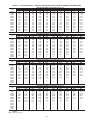
Table 9 — Fan Performance — 48P2,P3,P4,P5070 and 50P2,P3070 Units without Discharge Plenum*
AVAILABLE EXTERNAL STATIC PRESSURE (in. wg)
AIRFLOW
(cfm)
14,000
17,500
21,000
24,500
28,000
30,000
0.2
0.4
0.6
0.8
1.0
1.2
1.4
1.6
Rpm
Bhp
Rpm
Bhp
Rpm
Bhp
Rpm
Bhp
Rpm
Bhp
Rpm
Bhp
Rpm
Bhp
Rpm
Bhp
258
302
348
397
447
476
2.23
3.92
6.36
9.74
14.18
17.29
297
338
380
424
470
497
2.80
4.67
7.29
10.80
15.35
18.50
330
368
408
450
494
519
3.38
5.39
8.18
11.88
16.60
19.82
362
395
434
475
516
541
4.02
6.10
9.04
12.91
17.82
21.15
392
421
457
497
538
562
4.73
6.84
9.88
13.91
19.01
22.45
422
446
479
517
558
581
5.53
7.64
10.74
14.89
20.16
23.70
451
471
501
537
576
599
6.42
8.50
11.64
15.88
21.29
24.93
480
495
522
556
594
617
7.37
9.42
12.57
16.89
22.41
26.14
AVAILABLE EXTERNAL STATIC PRESSURE (in. wg)
AIRFLOW
(cfm)
14,000
17,500
21,000
24,500
28,000
30,000
1.8
2.0
2.2
2.4
2.6
2.8
3.0
3.2
Rpm
Bhp
Rpm
Bhp
Rpm
Bhp
Rpm
Bhp
Rpm
Bhp
Rpm
Bhp
Rpm
Bhp
Rpm
Bhp
507
519
543
575
612
634
8.39
10.42
13.56
17.93
23.55
27.34
533
542
563
593
628
650
9.46
11.48
14.60
18.99
24.69
28.56
558
565
583
611
645
666
10.57
12.60
15.69
20.10
25.86
29.78
582
588
603
629
661
681
11.71
13.78
16.84
21.24
27.05
31.02
605
610
623
646
677
696
12.89
15.02
18.05
22.43
28.27
32.28
627
632
643
664
692
711
14.08
16.30
19.31
23.67
29.53
33.56
648
653
662
681
708
726
15.29
17.62
20.63
24.96
30.82
34.88
668
674
682
698
723
—
16.52
18.99
21.99
26.29
32.15
—
AVAILABLE EXTERNAL STATIC PRESSURE (in. wg)
AIRFLOW
(cfm)
14,000
17,500
21,000
24,500
28,000
30,000
3.4
3.6
3.8
4.0
Rpm
Bhp
Rpm
Bhp
Rpm
Bhp
Rpm
Bhp
687
694
701
715
739
—
17.76
20.38
23.41
27.67
33.51
—
706
713
719
732
—
—
19.01
21.79
24.87
29.10
—
—
724
732
738
749
—
—
20.27
23.24
26.38
30.58
—
—
741
—
—
—
—
—
21.54
—
—
—
—
—
2. See Component Pressure Drop data table before using Fan Performance tables.
3. Conversion — Bhp to kW:
LEGEND
48/50P3,P5 units only.
Bhp — Brake Horsepower
Kilowatts =
*If calculating static pressure for a 48 Series unit, be sure to add gas
heat pressure drop from Component Pressure Drop table.
NOTES:
1. Fan performance is based on wet coils and clean 2-in. filters.
Bhp x .746
Motor efficiency
See Physical Data table for motor efficiency.
14
Table 10 — Fan Performance — 50P2,P3030 Units with Discharge Plenum and 50P4,P5030 Units
AVAILABLE EXTERNAL STATIC PRESSURE (in. wg)
AIRFLOW
(cfm)
6,000
7,500
9,000
10,500
12,000
13,500
15,000
0.2
0.4
0.6
0.8
1.0
1.2
1.4
1.6
Rpm
Bhp
Rpm
Bhp
Rpm
Bhp
Rpm
Bhp
Rpm
Bhp
Rpm
Bhp
Rpm
Bhp
Rpm
Bhp
255
291
330
371
413
456
500
0.95
1.51
2.28
3.28
4.56
6.12
7.99
313
340
372
408
447
487
528
1.35
1.93
2.73
3.76
5.07
6.66
8.58
364
386
413
444
479
516
555
1.82
2.41
3.22
4.28
5.61
7.23
9.18
411
428
451
479
510
544
581
2.35
2.94
3.76
4.84
6.19
7.83
9.80
454
468
487
512
540
572
606
2.92
3.51
4.34
5.43
6.80
8.46
10.45
494
505
522
544
570
599
631
3.52
4.13
4.96
6.06
7.44
9.12
11.13
530
541
555
574
598
626
656
4.14
4.78
5.61
6.71
8.11
9.81
11.83
563
574
587
604
626
651
680
4.78
5.46
6.30
7.40
8.80
10.51
12.56
AVAILABLE EXTERNAL STATIC PRESSURE (in. wg)
AIRFLOW
(cfm)
6,000
7,500
9,000
10,500
12,000
13,500
15,000
1.8
2.0
2.2
2.4
2.6
2.8
3.0
3.2
Rpm
Bhp
Rpm
Bhp
Rpm
Bhp
Rpm
Bhp
Rpm
Bhp
Rpm
Bhp
Rpm
Bhp
Rpm
Bhp
594
605
617
633
652
676
703
5.43
6.16
7.02
8.12
9.52
11.25
13.30
623
635
646
660
679
701
726
6.09
6.88
7.76
8.86
10.27
12.00
14.07
651
664
674
687
704
725
749
6.75
7.62
8.52
9.64
11.04
12.78
14.86
676
691
702
713
729
748
771
7.41
8.36
9.31
10.43
11.84
13.58
15.66
701
716
728
739
753
771
793
8.08
9.11
10.11
11.25
12.66
14.40
16.49
725
741
753
764
777
794
814
8.75
9.88
10.93
12.09
13.50
15.24
17.34
747
765
777
788
800
816
835
9.42
10.64
11.76
12.95
14.37
16.11
18.20
769
787
800
811
823
838
856
10.10
11.41
12.60
13.82
15.26
16.99
19.09
AVAILABLE EXTERNAL STATIC PRESSURE (in. wg)
AIRFLOW
(cfm)
6,000
7,500
9,000
10,500
12,000
13,500
15,000
3.4
3.6
3.8
4.0
Rpm
Bhp
Rpm
Bhp
Rpm
Bhp
Rpm
Bhp
789
809
823
833
845
859
876
10.77
12.18
13.44
14.71
16.16
17.90
20.00
809
830
844
856
867
880
896
11.45
12.96
14.29
15.61
17.08
18.82
20.92
829
851
866
877
888
—
—
12.13
13.73
15.15
16.52
18.01
—
—
848
870
886
898
—
—
—
12.81
14.51
16.01
17.44
—
—
—
LEGEND
2. See Component Pressure Drop data table before using Fan Performance tables.
3. Conversion — Bhp to kW:
50P3,P5 units only.
Bhp — Brake Horsepower
Kilowatts =
NOTES:
1. Fan performance is based on wet coils and clean 2-in. filters.
Bhp x .746
Motor efficiency
See Physical Data table for motor efficiency.
15
Table 11 — Fan Performance — 50P2,P3035 Units with Discharge Plenum and 50P4,P5035 Units
AVAILABLE EXTERNAL STATIC PRESSURE (in. wg)
AIRFLOW
(cfm)
7,000
8,000
10,000
12,000
14,000
15,000
0.2
0.4
0.6
0.8
1.0
1.2
1.4
1.6
Rpm
Bhp
Rpm
Bhp
Rpm
Bhp
Rpm
Bhp
Rpm
Bhp
Rpm
Bhp
Rpm
Bhp
Rpm
Bhp
285
311
367
426
486
517
1.35
1.81
3.04
4.74
6.98
8.33
337
358
406
459
515
544
1.78
2.25
3.52
5.26
7.55
8.92
384
402
443
491
543
570
2.26
2.75
4.05
5.82
8.15
9.54
428
442
479
522
570
596
2.80
3.29
4.61
6.42
8.78
10.18
469
481
512
552
597
621
3.38
3.87
5.21
7.05
9.44
10.85
507
517
545
581
623
646
4.00
4.50
5.84
7.70
10.12
11.55
542
551
576
609
649
671
4.66
5.16
6.51
8.38
10.83
12.27
576
584
606
637
674
694
5.34
5.86
7.21
9.09
11.55
13.01
AVAILABLE EXTERNAL STATIC PRESSURE (in. wg)
AIRFLOW
(cfm)
7,000
8,000
10,000
12,000
14,000
15,000
1.8
2.0
2.2
2.4
2.6
2.8
3.0
3.2
Rpm
Bhp
Rpm
Bhp
Rpm
Bhp
Rpm
Bhp
Rpm
Bhp
Rpm
Bhp
Rpm
Bhp
Rpm
Bhp
607
615
636
663
698
718
6.03
6.58
7.94
9.83
12.31
13.78
637
645
664
689
722
741
6.74
7.32
8.70
10.59
13.08
14.56
665
673
691
715
745
763
7.46
8.07
9.48
11.38
13.88
15.36
691
700
717
739
768
785
8.18
8.84
10.29
12.19
14.69
16.19
717
726
743
764
791
807
8.91
9.62
11.11
13.03
15.53
17.03
741
751
768
787
813
828
9.65
10.41
11.96
13.88
16.39
17.90
764
775
792
810
834
849
10.39
11.20
12.82
14.76
17.27
18.78
786
797
815
833
856
869
11.13
12.00
13.69
15.66
18.17
19.69
AVAILABLE EXTERNAL STATIC PRESSURE (in. wg)
AIRFLOW
(cfm)
7,000
8,000
10,000
12,000
14,000
15,000
3.4
3.6
3.8
4.0
Rpm
Bhp
Rpm
Bhp
Rpm
Bhp
Rpm
Bhp
807
819
837
855
876
890
11.88
12.80
14.57
16.57
19.10
20.61
828
841
859
876
897
—
12.62
13.61
15.47
17.51
20.04
—
848
861
881
897
—
—
13.37
14.42
16.37
18.45
—
—
867
881
——
—
—
14.12
15.23
—
—
—
—
LEGEND
2. See Component Pressure Drop data table before using Fan Performance tables.
3. Conversion — Bhp to kW:
50P3,P5 units only.
Bhp — Brake Horsepower
Kilowatts =
NOTES:
1. Fan performance is based on wet coils and clean 2-in. filters.
Bhp x .746
Motor efficiency
See Physical Data table for motor efficiency.
16
Table 12 — Fan Performance — 50P2,P3040 Units with Discharge Plenum and 50P4,P5040 Units
AVAILABLE EXTERNAL STATIC PRESSURE (in. wg)
AIRFLOW
(cfm)
8,000
10,000
12,000
14,000
16,000
18,000
20,000
0.2
0.4
0.6
0.8
1.0
1.2
1.4
1.6
Rpm
Bhp
Rpm
Bhp
Rpm
Bhp
Rpm
Bhp
Rpm
Bhp
Rpm
Bhp
Rpm
Bhp
Rpm
Bhp
293
343
395
449
504
559
615
1.62
2.66
4.09
5.97
8.32
11.20
14.66
344
385
431
481
533
586
640
2.10
3.19
4.68
6.62
9.06
12.04
15.59
390
425
466
512
560
611
663
2.62
3.76
5.29
7.28
9.77
12.82
16.44
432
463
500
541
587
635
685
3.18
4.36
5.93
7.96
10.50
13.59
17.28
470
498
532
570
613
659
707
3.76
4.99
6.60
8.67
11.25
14.38
18.11
507
532
562
598
638
682
728
4.36
5.64
7.30
9.40
12.02
15.19
18.96
541
563
592
626
663
705
749
4.97
6.31
8.01
10.16
12.81
16.01
19.83
573
594
620
652
688
727
770
5.60
7.00
8.75
10.93
13.62
16.86
20.71
AVAILABLE EXTERNAL STATIC PRESSURE (in. wg)
AIRFLOW
(cfm)
8,000
10,000
12,000
14,000
16,000
18,000
20,000
1.8
2.0
2.2
2.4
2.6
2.8
3.0
3.2
Rpm
Bhp
Rpm
Bhp
Rpm
Bhp
Rpm
Bhp
Rpm
Bhp
Rpm
Bhp
Rpm
Bhp
Rpm
Bhp
603
623
648
677
712
749
790
6.23
7.70
9.50
11.73
14.45
17.73
21.61
632
651
674
702
735
771
811
6.87
8.41
10.26
12.54
15.30
18.61
22.52
659
678
699
726
757
792
830
7.50
9.13
11.04
13.35
16.16
19.50
23.45
685
703
724
750
779
813
—
8.14
9.86
11.83
14.19
17.03
20.42
—
710
728
748
772
801
833
—
8.78
10.60
12.63
15.04
17.92
21.34
—
734
752
772
795
822
853
—
9.43
11.33
13.44
15.89
18.82
22.27
—
757
776
794
817
843
873
—
10.07
12.08
14.25
16.76
19.73
23.23
—
779
798
817
838
863
—
—
10.71
12.82
15.07
17.64
20.65
—
—
AVAILABLE EXTERNAL STATIC PRESSURE (in. wg)
AIRFLOW
(cfm)
8,000
10,000
12,000
14,000
16,000
18,000
20,000
3.4
3.6
3.8
4.0
Rpm
Bhp
Rpm
Bhp
Rpm
Bhp
Rpm
Bhp
800
820
838
859
883
—
—
11.35
13.57
15.90
18.53
21.58
—
—
821
841
859
879
—
—
—
12.00
14.31
16.73
19.42
—
—
—
841
862
880
899
—
—
—
12.64
15.06
17.57
20.32
—
—
—
860
882
900
—
—
—
—
13.28
15.81
18.40
—
—
—
—
LEGEND
2. See Component Pressure Drop data table before using Fan Performance tables.
3. Conversion — Bhp to kW:
50P3,P5 units only.
Bhp — Brake Horsepower
Kilowatts =
NOTES:
1. Fan performance is based on wet coils and clean 2-in. filters.
Bhp x .746
Motor efficiency
See Physical Data table for motor efficiency.
17
Table 13 — Fan Performance — 50P2,P3050 Units with Discharge Plenum and 50P4,P5050 Units
AVAILABLE EXTERNAL STATIC PRESSURE (in. wg)
AIRFLOW
(cfm)
9,000
10,000
12,000
14,000
16,000
18,000
20,000
0.2
0.4
0.6
0.8
1.0
1.2
1.4
1.6
Rpm
Bhp
Rpm
Bhp
Rpm
Bhp
Rpm
Bhp
Rpm
Bhp
Rpm
Bhp
Rpm
Bhp
Rpm
Bhp
324
349
403
459
515
573
630
2.15
2.74
4.23
6.17
8.63
11.65
15.28
369
392
439
490
544
599
654
2.67
3.28
4.82
6.83
9.34
12.44
16.14
412
431
474
521
571
623
677
3.23
3.87
5.45
7.50
10.07
13.21
16.97
452
469
507
550
597
647
699
3.83
4.48
6.11
8.20
10.82
14.00
17.81
488
504
539
579
623
671
720
4.44
5.12
6.80
8.93
11.59
14.82
18.66
523
537
570
607
649
694
741
5.08
5.78
7.51
9.69
12.38
15.65
19.53
556
569
599
634
674
716
762
5.73
6.46
8.23
10.46
13.20
16.50
20.43
587
599
627
660
698
739
783
6.40
7.16
8.98
11.25
14.03
17.37
21.34
AVAILABLE EXTERNAL STATIC PRESSURE (in. wg)
AIRFLOW
(cfm)
9,000
10,000
12,000
14,000
16,000
18,000
20,000
1.8
2.0
2.2
2.4
2.6
2.8
3.0
3.2
Rpm
Bhp
Rpm
Bhp
Rpm
Bhp
Rpm
Bhp
Rpm
Bhp
Rpm
Bhp
Rpm
Bhp
Rpm
Bhp
617
628
654
686
721
761
803
7.08
7.87
9.74
12.06
14.88
18.27
22.27
645
656
680
710
744
782
823
7.77
8.59
10.51
12.88
15.74
19.17
23.21
672
682
706
734
767
803
—
8.47
9.33
11.30
13.71
16.62
20.09
—
698
708
730
757
789
824
—
9.18
10.07
12.10
14.55
17.51
21.02
—
723
733
754
780
810
844
—
9.90
10.82
12.90
15.41
18.41
21.96
—
747
757
778
802
831
864
—
10.62
11.58
13.73
16.27
19.32
22.92
—
770
780
800
824
852
884
—
11.34
12.35
14.56
17.15
20.24
23.88
—
793
802
822
845
872
—
—
12.07
13.12
15.39
18.04
21.17
—
—
AVAILABLE EXTERNAL STATIC PRESSURE (in. wg)
AIRFLOW
(cfm)
9,000
10,000
12,000
14,000
16,000
18,000
20,000
3.4
3.6
3.8
4.0
Rpm
Bhp
Rpm
Bhp
Rpm
Bhp
Rpm
Bhp
814
824
844
866
892
—
—
12.79
13.89
16.24
18.94
22.12
—
—
835
845
865
886
—
—
—
13.52
14.67
17.09
19.85
—
—
—
855
866
885
—
—
—
—
14.25
15.45
17.95
—
—
—
—
875
886
—
—
—
—
—
14.99
16.23
—
—
—
—
—
LEGEND
2. See Component Pressure Drop data table before using Fan Performance tables.
3. Conversion — Bhp to kW:
50P3,P5 units only.
Bhp — Brake Horsepower
Kilowatts =
NOTES:
1. Fan performance is based on wet coils and clean 2-in. filters.
Bhp x .746
Motor efficiency
See Physical Data table for motor efficiency.
18
Table 14 — Fan Performance — 50P2,P3055 Units with Discharge Plenum and 50P4,P5055 Units
AVAILABLE EXTERNAL STATIC PRESSURE (in. wg)
AIRFLOW
(cfm)
10,000
12,500
15,000
17,500
20,000
22,500
25,000
0.2
0.4
0.6
0.8
1.0
1.2
1.4
1.6
Rpm
Bhp
Rpm
Bhp
Rpm
Bhp
Rpm
Bhp
Rpm
Bhp
Rpm
Bhp
Rpm
Bhp
Rpm
Bhp
217
248
281
315
351
389
427
1.21
2.01
3.13
4.64
6.64
9.20
12.39
258
286
317
348
381
414
449
1.71
2.63
3.90
5.55
7.64
10.25
13.48
296
319
347
378
409
440
473
2.29
3.26
4.64
6.43
8.68
11.43
14.75
334
349
374
403
433
464
496
2.97
3.95
5.38
7.29
9.68
12.59
16.06
371
380
400
426
456
486
517
3.76
4.71
6.18
8.16
10.66
13.71
17.34
407
410
425
449
477
506
537
4.63
5.58
7.03
9.05
11.64
14.81
18.59
440
440
450
471
497
525
555
5.56
6.52
7.95
10.00
12.65
15.91
19.82
471
469
476
493
516
543
573
6.51
7.54
8.95
10.99
13.68
17.03
21.04
AVAILABLE EXTERNAL STATIC PRESSURE (in. wg)
AIRFLOW
(cfm)
10,000
12,500
15,000
17,500
20,000
22,500
25,000
1.8
2.0
2.2
2.4
2.6
2.8
3.0
3.2
Rpm
Bhp
Rpm
Bhp
Rpm
Bhp
Rpm
Bhp
Rpm
Bhp
Rpm
Bhp
Rpm
Bhp
Rpm
Bhp
500
498
501
514
535
561
590
7.48
8.63
10.03
12.05
14.76
18.17
22.27
527
525
526
536
554
579
606
8.46
9.76
11.17
13.17
15.88
19.34
23.51
552
552
550
557
573
596
622
9.45
10.93
12.38
14.35
17.06
20.54
24.78
576
577
575
579
592
613
637
10.44
12.12
13.65
15.60
18.29
21.78
26.07
598
601
598
600
611
629
653
11.42
13.32
14.97
16.91
19.58
23.06
27.39
619
624
621
621
630
646
668
12.41
14.54
16.32
18.28
20.91
24.40
28.75
639
646
644
643
649
663
683
13.41
15.76
17.71
19.70
22.31
25.78
30.13
659
667
666
663
668
680
699
14.41
16.99
19.11
21.18
23.77
27.20
31.56
AVAILABLE EXTERNAL STATIC PRESSURE (in. wg)
AIRFLOW
(cfm)
10,000
12,500
15,000
17,500
20,000
22,500
25,000
3.4
3.6
3.8
4.0
Rpm
Bhp
Rpm
Bhp
Rpm
Bhp
Rpm
Bhp
677
687
687
684
686
697
714
15.40
18.22
20.54
22.69
25.27
28.68
33.04
695
706
707
704
705
713
729
16.40
19.45
21.98
24.24
26.84
30.21
34.55
712
725
727
724
723
730
—
17.40
20.69
23.43
25.83
28.44
31.79
—
728
742
746
743
742
747
—
18.41
21.92
24.89
27.43
30.09
33.42
—
LEGEND
2. See Component Pressure Drop data table before using Fan Performance tables.
3. Conversion — Bhp to kW:
50P3,P5 units only.
Bhp — Brake Horsepower
Kilowatts =
NOTES:
1. Fan performance is based on wet coils and clean 2-in. filters.
Bhp x .746
Motor efficiency
See Physical Data table for motor efficiency.
19
Table 15 — Fan Performance — 50P2,P3060 Units with Discharge Plenum and 50P4,P5060 Units
AVAILABLE EXTERNAL STATIC PRESSURE (in. wg)
AIRFLOW
(cfm)
12,000
15,000
18,000
21,000
24,000
27,000
30,000
0.2
0.4
0.6
0.8
1.0
1.2
1.4
1.6
Rpm
Bhp
Rpm
Bhp
Rpm
Bhp
Rpm
Bhp
Rpm
Bhp
Rpm
Bhp
Rpm
Bhp
Rpm
Bhp
241
281
323
366
410
455
500
1.82
3.14
5.03
7.61
10.97
15.23
20.52
280
316
355
395
437
479
522
2.41
3.87
5.92
8.66
12.20
16.65
22.11
314
346
382
421
460
501
543
3.04
4.61
6.80
9.69
13.39
18.00
23.64
346
374
408
444
482
522
563
3.72
5.38
7.68
10.71
14.55
19.33
25.14
376
400
431
466
503
542
581
4.47
6.19
8.58
11.73
15.71
20.64
26.61
405
426
454
487
523
560
599
5.26
7.05
9.53
12.78
16.88
21.95
28.06
433
450
476
507
541
578
616
6.11
7.95
10.50
13.85
18.07
23.26
29.52
460
474
498
527
560
595
632
7.01
8.90
11.52
14.94
19.27
24.58
30.97
AVAILABLE EXTERNAL STATIC PRESSURE (in. wg)
AIRFLOW
(cfm)
12,000
15,000
18,000
21,000
24,000
27,000
30,000
1.8
2.0
2.2
2.4
2.6
2.8
3.0
3.2
Rpm
Bhp
Rpm
Bhp
Rpm
Bhp
Rpm
Bhp
Rpm
Bhp
Rpm
Bhp
Rpm
Bhp
Rpm
Bhp
486
498
518
546
577
611
648
7.94
9.90
12.57
16.07
20.49
25.91
32.43
511
520
539
564
594
628
663
8.91
10.93
13.66
17.23
21.74
27.26
33.90
535
543
559
583
611
643
678
9.91
12.01
14.78
18.42
23.00
28.63
35.38
559
564
579
600
628
659
—
10.94
13.11
15.95
19.64
24.31
30.03
—
581
586
598
618
644
674
—
11.99
14.26
17.15
20.90
25.63
31.44
—
603
606
617
635
660
689
—
13.07
15.43
18.39
22.19
26.99
32.87
—
624
627
636
653
676
703
—
14.16
16.63
19.65
23.51
28.38
34.33
—
645
646
654
669
691
718
—
15.28
17.86
20.95
24.86
29.77
35.82
—
AVAILABLE EXTERNAL STATIC PRESSURE (in. wg)
AIRFLOW
(cfm)
12,000
15,000
18,000
21,000
24,000
27,000
30,000
3.4
3.6
3.8
4.0
Rpm
Bhp
Rpm
Bhp
Rpm
Bhp
Rpm
Bhp
664
666
672
686
707
—
—
16.40
19.12
22.28
26.25
31.23
—
—
683
685
690
703
722
—
—
17.55
20.39
23.64
27.67
32.71
—
—
702
703
708
719
737
—
—
18.70
21.69
25.02
29.11
34.20
—
—
720
721
725
735
—
—
—
19.87
23.01
26.44
30.59
—
—
—
LEGEND
2. See Component Pressure Drop data table before using Fan Performance tables.
3. Conversion — Bhp to kW:
50P3,P5 units only.
Bhp — Brake Horsepower
Kilowatts =
NOTES:
1. Fan performance is based on wet coils and clean 2-in. filters.
Bhp x .746
Motor efficiency
See Physical Data table for motor efficiency.
20
Table 16 — Fan Performance — 50P2,P3070 Units with Discharge Plenum and 50P4,P5070 Units
AVAILABLE EXTERNAL STATIC PRESSURE (in. wg)
AIRFLOW
(cfm)
14,000
17,500
21,000
24,500
28,000
30,000
0.2
0.4
0.6
0.8
1.0
1.2
1.4
1.6
Rpm
Bhp
Rpm
Bhp
Rpm
Bhp
Rpm
Bhp
Rpm
Bhp
Rpm
Bhp
Rpm
Bhp
Rpm
Bhp
268
316
366
417
470
500
2.64
4.67
7.61
11.61
16.88
20.52
304
348
395
444
493
522
3.32
5.54
8.66
12.87
18.35
22.11
335
376
421
467
515
543
4.02
6.39
9.69
14.09
19.77
23.64
364
402
444
489
536
563
4.76
7.25
10.71
15.28
21.15
25.14
391
426
466
509
555
581
5.55
8.14
11.73
16.47
22.51
26.61
418
449
487
529
573
599
6.39
9.06
12.78
17.66
23.87
28.06
444
472
507
547
590
616
7.27
10.03
13.85
18.86
25.22
29.52
468
493
527
565
607
632
8.20
11.03
14.94
20.08
26.59
30.97
AVAILABLE EXTERNAL STATIC PRESSURE (in. wg)
AIRFLOW
(cfm)
14,000
17,500
21,000
24,500
28,000
30,000
1.8
2.0
2.2
2.4
2.6
2.8
3.0
3.2
Rpm
Bhp
Rpm
Bhp
Rpm
Bhp
Rpm
Bhp
Rpm
Bhp
Rpm
Bhp
Rpm
Bhp
Rpm
Bhp
493
515
546
583
623
648
9.17
12.07
16.07
21.32
27.96
32.43
516
535
564
600
639
663
10.19
13.14
17.23
22.59
29.35
33.90
539
556
583
616
655
678
11.24
14.26
18.42
23.87
30.75
35.38
562
576
600
633
670
—
12.33
15.42
19.64
25.18
32.18
—
583
595
618
649
685
—
13.45
16.61
20.90
26.53
33.63
—
605
615
635
664
699
—
14.60
17.84
22.19
27.89
35.09
—
625
634
653
680
—
—
15.77
19.09
23.51
29.29
—
—
645
652
669
695
—
—
16.96
20.39
24.86
30.71
—
—
AVAILABLE EXTERNAL STATIC PRESSURE (in. wg)
AIRFLOW
(cfm)
14,000
17,500
21,000
24,500
28,000
30,000
3.4
3.6
3.8
4.0
Rpm
Bhp
Rpm
Bhp
Rpm
Bhp
Rpm
Bhp
665
671
686
711
—
—
18.18
21.70
26.24
32.17
—
—
684
689
703
726
—
—
19.42
23.05
27.67
33.65
—
—
703
706
719
741
—
—
20.68
24.42
29.11
35.16
—
—
721
724
735
—
—
—
21.95
25.82
30.59
—
—
—
LEGEND
2. See Component Pressure Drop data table before using Fan Performance tables.
3. Conversion — Bhp to kW:
50P3,P5 units only.
Bhp — Brake Horsepower
Kilowatts =
NOTES:
1. Fan performance is based on wet coils and clean 2-in. filters.
Bhp x .746
Motor efficiency
See Physical Data table for motor efficiency.
21
Table 17 — Fan Performance — 48/50P2,P3,P4,P5075 Units with Forward-Curved Fan*
AVAILABLE EXTERNAL STATIC PRESSURE (in. wg)
AIRFLOW
(Cfm)
14,000
16,000
18,000
20,000
22,000
24,000
26,000
28,000
30,000
0.2
0.4
0.6
0.8
1.0
1.2
1.4
1.6
Rpm
Bhp
Rpm
Bhp
Rpm
Bhp
Rpm
Bhp
Rpm
Bhp
Rpm
Bhp
Rpm
Bhp
Rpm
Bhp
211
232
253
275
298
320
343
367
390
2.35
3.27
4.42
5.83
7.53
9.55
11.91
14.65
17.78
243
261
281
301
321
342
364
386
408
3.06
4.06
5.31
6.82
8.62
10.75
13.22
16.06
19.31
272
288
305
324
343
363
384
405
426
3.80
4.88
6.21
7.81
9.70
11.93
14.50
17.45
20.80
299
313
329
346
364
383
402
422
443
4.59
5.74
7.14
8.82
10.80
13.11
15.78
18.83
22.28
325
337
351
366
383
401
420
439
459
5.43
6.65
8.11
9.86
11.92
14.31
17.07
20.20
23.75
349
360
372
386
402
419
437
455
474
6.30
7.59
912
10.94
13.07
15.54
18.37
21.59
25.24
372
381
393
406
420
436
453
471
489
7.21
8.57
10.17
12.05
14.25
16.79
19.70
23.00
26.73
395
402
413
425
438
453
469
486
504
8.15
9.58
11.25
13.20
15.46
18.07
21.05
24.43
28.24
AVAILABLE EXTERNAL STATIC PRESSURE (in. wg)
AIRFLOW
(Cfm)
14,000
16,000
18,000
20,000
22,000
24,000
26,000
28,000
30,000
1.8
2.0
2.2
2.4
2.6
2.8
3.0
3.2
Rpm
Bhp
Rpm
Bhp
Rpm
Hp
Rpm
Hp
Rpm
Hp
Rpm
Hp
Rpm
Hp
Rpm
Hp
416
423
432
443
455
470
485
501
518
9.12
10.62
12.36
14.38
16.70
19.38
22.43
25.89
29.76
437
442
450
460
472
486
500
516
533
10.10
11.68
13.50
15.58
17.98
20.72
23.83
27.36
31.32
457
462
469
478
489
501
515
530
546
11.10
12.77
14.66
16.82
19.28
22.08
25.27
28.86
32.89
476
480
486
495
505
517
530
544
560
12.13
13.88
15.84
18.07
20.60
23.48
26.73
30.38
34.48
495
498
504
511
521
532
544
558
573
13.17
15.00
17.05
19.35
21.96
24.89
28.22
31.94
36.10
513
516
521
527
536
547
559
572
586
14.22
16.15
18.27
20.65
23.33
26.34
29.72
33.51
37.74
531
533
537
543
551
561
573
585
599
15.29
17.31
19.53
21.98
24.72
27.80
31.26
35.11
39.41
548
550
553
559
566
576
586
599
612
16.38
18.48
20.78
23.32
26.14
29.29
32.81
36.74
41.11
AVAILABLE EXTERNAL STATIC PRESSURE (in. wg)
AIRFLOW
(Cfm)
14,000
16,000
18,000
20,000
22,000
24,000
26,000
28,000
30,000
3.4
3.6
3.8
4.0
Rpm
Hp
Rpm
Hp
Rpm
Hp
Rpm
Hp
564
566
569
574
581
590
600
612
624
17.47
19.68
22.06
24.68
27.57
30.80
34.39
38.38
42.81
581
582
585
589
596
604
613
624
637
18.58
20.88
23.36
26.06
29.04
32.33
35.99
40.05
44.54
596
597
600
604
610
617
627
637
649
19.71
22.10
24.66
27.45
30.51
33.88
37.61
41.74
46.29
612
613
615
618
624
631
640
650
661
20.84
23.33
25.99
28.85
31.99
35.44
39.24
43.44
48.06
2. For return fan and high-capacity power exhaust units, add component pressure drop for economizer. Do not add component
pressure drop for power exhaust.
3. See Component Pressure Drop data table before using Fan Performance tables.
4. Conversion — Bhp to kW:
LEGEND
48/50P3,P5 units only.
Bhp — Brake Horsepower
*If calculating static pressure for a 48 Series unit, be sure to add gas
heat pressure drop from Component Pressure Drop table.
NOTES:
1. Fan performance is based on wet coils and clean 2-in. filters.
Kilowatts =
22
Bhp x .746
Motor efficiency
Table 18 — Fan Performance — 48/50P2,P3,P4,P5075 Units with Airfoil Fan*
AVAILABLE EXTERNAL STATIC PRESSURE (in. wg)
AIRFLOW
(Cfm)
15,000
16,000
18,000
20,000
22,000
24,000
26,000
28,000
30,000
0.30
0.60
0.90
1.20
1.50
1.80
2.10
2.40
Rpm
Bhp
Rpm
Bhp
Rpm
Bhp
Rpm
Bhp
Rpm
Bhp
Rpm
Bhp
Rpm
Bhp
Rpm
Bhp
620
655
725
795
867
939
1012
1084
1157
3.02
3.52
4.68
6.08
7.75
9.71
11.99
14.61
17.60
671
703
769
836
904
974
1044
1115
1186
3.91
4.45
5.71
7.22
9.00
11.07
13.46
16.18
19.28
720
749
810
874
940
1007
1075
1144
1214
4.83
5.41
6.76
8.36
10.24
12.41
14.90
17.73
20.93
767
794
851
911
974
1039
1105
1172
1240
5.80
6.42
7.84
9.52
11.49
13.75
16.34
19.28
22.57
813
838
891
947
1008
1070
1134
1200
1267
6.81
7.47
8.96
10.71
12.76
15.11
17.79
20.82
24.22
858
881
930
983
1041
1101
1163
1227
1292
7.87
8.56
10.12
11.94
14.06
16.49
19.25
22.37
25.86
902
922
968
1019
1073
1131
1191
1253
1317
8.97
9.69
11.32
13.20
15.39
17.90
20.74
23.94
27.51
944
963
1006
1054
1105
1161
1219
1280
1342
10.10
10.86
12.55
14.51
16.76
19.33
22.25
25.52
29.18
AVAILABLE EXTERNAL STATIC PRESSURE (in. wg)
AIRFLOW
(Cfm)
15,000
16,000
18,000
20,000
22,000
24,000
26,000
28,000
30,000
2.70
3.00
3.30
3.60
3.90
4.20
4.50
4.80
Rpm
Bhp
Rpm
Bhp
Rpm
Bhp
Rpm
Bhp
Rpm
Bhp
Rpm
Bhp
Rpm
Bhp
Rpm
Bhp
984
1003
1043
1088
1137
1191
1247
1306
1367
11.25
12.06
13.82
15.84
18.15
20.79
23.78
27.12
30.86
1023
1041
1079
1122
1169
1220
1274
1332
1391
12.42
13.27
15.12
17.21
19.58
22.28
25.33
28.75
32.57
1061
1078
1114
1155
1200
1249
1302
1357
1415
13.60
14.51
16.44
18.60
21.05
23.81
26.92
30.41
34.29
1097
1113
1149
1188
1231
1278
1329
1383
1439
14.80
15.76
17.79
20.02
22.54
25.36
28.53
32.08
36.03
1131
1148
1182
1220
1261
1307
1356
1408
1463
16.00
17.02
19.15
21.47
24.05
26.94
30.18
33.79
37.81
1165
1181
1215
1251
1291
1335
1382
1433
1487
17.22
18.29
20.52
22.93
25.59
28.55
31.85
35.52
39.60
1198
1214
1247
1282
1321
1363
1409
1458
1510
18.44
19.56
21.91
24.42
27.15
30.18
33.54
37.28
41.42
1229
1245
1278
1312
1350
1390
1435
1483
1534
19.67
20.85
23.31
25.91
28.74
31.83
35.26
39.05
43.25
AVAILABLE EXTERNAL STATIC PRESSURE (in. wg)
AIRFLOW
(Cfm)
15,000
16,000
18,000
20,000
22,000
24,000
26,000
28,000
30,000
5.10
5.40
5.70
6.00
Rpm
Bhp
Rpm
Bhp
Rpm
Bhp
Rpm
Bhp
1260
1276
1308
1342
1378
1418
1461
1507
1557
20.91
22.15
24.71
27.42
30.33
33.51
37.00
40.86
45.12
1290
1305
1337
1370
1406
1445
1487
1532
1580
22.15
23.45
26.13
28.95
31.95
35.20
38.76
42.69
47.01
1319
1334
1366
1399
1434
1471
1512
1556
1603
23.41
24.76
27.56
30.48
33.57
36.91
40.54
44.54
48.92
1347
1362
1394
1426
1461
1497
1537
1580
1626
24.66
26.08
28.99
32.02
35.21
38.64
42.35
46.40
50.85
2. For return fan high-capacity power exhaust units, add component
pressure drop for economizer. Do not add component pressure
drop for power exhaust.
3. See Component Pressure Drop data table before using Fan Performance tables.
4. Conversion — Bhp to kW:
LEGEND
48/50P3,P5 units only.
Bhp — Brake Horsepower
*If calculating static pressure for a 48 Series unit, be sure to add gas
heat pressure drop from Component Pressure Drop table.
NOTES:
1. Fan performance is based on wet coils and clean 2-in. filters.
Kilowatts =
23
Bhp x .746
Motor efficiency
Table 19 — Fan Performance — 48/50P2,P3,P4,P5090 Units with Forward-Curved Fan*
AVAILABLE EXTERNAL STATIC PRESSURE (in. wg)
AIRFLOW
(Cfm)
16,000
18,000
20,000
22,000
24,000
26,000
28,000
30,000
32,000
34,000
0.2
0.4
0.6
0.8
1.0
1.2
1.4
1.6
Rpm
Bhp
Rpm
Bhp
Rpm
Bhp
Rpm
Bhp
Rpm
Bhp
Rpm
Bhp
Rpm
Bhp
Rpm
Bhp
232
253
275
298
320
343
367
390
414
437
3.27
4.42
5.83
7.53
9.55
11.91
14.65
17.78
21.36
25.39
261
281
301
321
342
364
386
408
431
454
4.06
5.31
6.82
8.62
10.75
13.22
16.06
19.31
22.99
27.13
288
305
324
343
363
384
405
426
448
470
4.88
6.21
7.81
9.70
11.93
14.50
17.45
20.80
24.59
28.84
313
329
346
364
383
402
422
443
464
485
5.74
7.14
8.82
10.80
13.11
15.78
18.83
22.28
26.17
30.53
337
351
366
383
401
420
439
459
479
500
6.65
8.11
9.86
11.92
14.31
17.07
20.20
23.75
27.75
32.20
360
372
386
402
419
437
455
474
494
514
7.59
9.12
10.94
13.07
15.54
18.37
21.59
25.24
29.32
33.87
381
393
406
420
436
453
471
489
508
528
8.57
10.17
12.05
14.25
16.79
19.70
23.00
26.73
30.90
35.55
402
413
425
438
453
469
486
504
523
542
9.58
11.25
13.20
15.46
18.07
21.05
24.43
28.24
32.49
37.23
AVAILABLE EXTERNAL STATIC PRESSURE (in. wg)
AIRFLOW
(Cfm)
16,000
18,000
20,000
22,000
24,000
26,000
28,000
30,000
32,000
34,000
1.8
2.0
2.2
2.4
2.6
2.8
3.0
3.2
Rpm
Bhp
Rpm
Bhp
Rpm
Bhp
Rpm
Bhp
Rpm
Bhp
Rpm
Bhp
Rpm
Bhp
Rpm
Bhp
423
432
443
455
470
485
501
518
536
555
10.62
12.36
14.38
16.70
19.38
22.43
25.89
29.76
34.11
38.92
442
450
460
472
486
500
516
533
550
568
11.68
13.50
15.58
17.98
20.72
23.83
27.36
31.32
35.73
40.63
462
469
478
489
501
515
530
546
563
581
12.77
14.66
16.82
19.28
22.08
25.27
28.86
32.89
37.38
42.36
480
486
495
505
517
530
544
560
576
593
13.88
15.84
18.07
20.60
23.48
26.73
30.38
34.48
39.04
44.10
498
504
511
521
532
544
558
573
589
605
15.00
17.05
19.35
21.96
24.89
28.22
31.94
36.10
40.73
45.87
516
521
527
536
547
559
572
586
601
618
16.15
18.27
20.65
23.33
26.34
29.72
33.51
37.74
42.45
47.64
533
537
543
551
561
573
585
599
614
630
17.31
19.53
21.98
24.72
27.80
31.26
35.11
39.41
44.18
49.45
550
553
559
566
576
586
599
612
626
641
18.48
20.78
23.32
26.14
29.29
32.81
36.74
41.11
45.94
51.27
AVAILABLE EXTERNAL STATIC PRESSURE (in. wg)
AIRFLOW
(Cfm)
16,000
18,000
20,000
22,000
24,000
26,000
28,000
30,000
32,000
34,000
3.4
3.6
3.8
4.0
Rpm
Bhp
Rpm
Bhp
Rpm
Bhp
Rpm
Bhp
566
569
574
581
590
600
612
624
638
653
19.68
22.06
24.68
27.57
30.80
34.39
38.38
42.81
47.72
53.12
582
585
589
596
604
613
624
637
650
665
20.88
23.36
26.06
29.04
32.33
35.99
40.05
44.54
49.51
54.98
597
600
604
610
617
627
637
649
662
676
22.10
24.66
27.45
30.51
33.88
37.61
41.74
46.29
51.33
56.87
613
615
618
624
631
640
650
661
674
—
23.33
25.99
28.85
31.99
35.44
39.24
43.44
48.06
53.17
—
2. For return fan and high-capacity power exhaust units, add component pressure drop for economizer. Do not add component
pressure drop for power exhaust.
3. See Component Pressure Drop data table before using Fan Performance tables.
4. Conversion — Bhp to kW:
LEGEND
48/50P3,P5 units only.
Bhp — Brake Horsepower
*If calculating static pressure for a 48 Series unit, be sure to add gas
heat pressure drop from Component Pressure Drop table.
NOTES:
1. Fan performance is based on wet coils and clean 2-in. filters.
Kilowatts =
24
Bhp x .746
Motor efficiency
Table 20 — Fan Performance — 48/50P2,P3,P4,P5090 Units with Airfoil Fan*
AVAILABLE EXTERNAL STATIC PRESSURE (in. wg)
AIRFLOW
(Cfm)
17,000
18,000
20,000
22,000
24,000
26,000
28,000
30,000
32,000
34,000
0.30
0.60
0.90
1.20
1.50
1.80
2.10
2.40
Rpm
Bhp
Rpm
Bhp
Rpm
Bhp
Rpm
Bhp
Rpm
Bhp
Rpm
Bhp
Rpm
Bhp
Rpm
Bhp
690
725
795
867
939
1012
1084
1157
1231
1304
4.07
4.68
6.08
7.75
9.71
11.99
14.61
17.60
20.97
24.75
735
769
836
904
974
1044
1115
1186
1258
1330
5.05
5.71
7.22
9.00
11.07
13.46
16.18
19.28
22.76
26.65
779
810
874
940
1007
1075
1144
1214
1284
1355
6.06
6.76
8.36
10.24
12.41
14.90
17.73
20.93
24.52
28.52
822
851
911
974
1039
1105
1172
1240
1309
1379
7.10
7.84
9.52
11.49
13.75
16.34
19.28
22.57
26.26
30.36
863
891
947
1008
1070
1134
1200
1267
1334
1403
8.18
8.96
10.71
12.76
15.11
17.79
20.82
24.22
28.00
32.20
904
930
983
1041
1101
1163
1227
1292
1358
1426
9.31
10.12
11.94
14.06
16.49
19.25
22.37
25.86
29.74
34.04
945
968
1019
1073
1131
1191
1253
1317
1382
1448
10.47
11.32
13.20
15.39
17.90
20.74
23.94
27.51
31.48
35.87
984
1006
1054
1105
1161
1219
1280
1342
1406
1471
11.68
12.55
14.51
16.76
19.33
22.25
25.52
29.18
33.23
37.71
AVAILABLE EXTERNAL STATIC PRESSURE (in. wg)
AIRFLOW
(Cfm)
17,000
18,000
20,000
22,000
24,000
26,000
28,000
30,000
32,000
34,000
2.70
3.00
3.30
3.60
3.90
4.20
4.50
4.80
Rpm
Bhp
Rpm
Bhp
Rpm
Bhp
Rpm
Bhp
Rpm
Bhp
Rpm
Bhp
Rpm
Bhp
Rpm
Bhp
1022
1043
1088
1137
1191
1247
1306
1367
1429
1493
12.91
13.82
15.84
18.15
20.79
23.78
27.12
30.86
35.00
39.57
1059
1079
1122
1169
1220
1274
1332
1391
1452
1515
14.17
15.12
17.21
19.58
22.28
25.33
28.75
32.57
36.78
41.43
1096
1114
1155
1200
1249
1302
1357
1415
1475
1537
15.45
16.44
18.60
21.05
23.81
26.92
30.41
34.29
38.58
43.31
1131
1149
1188
1231
1278
1329
1383
1439
1498
1558
16.75
17.79
20.02
22.54
25.36
28.53
32.08
36.03
40.40
45.20
1165
1182
1220
1261
1307
1356
1408
1463
1520
1580
18.06
19.15
21.47
24.05
26.94
30.18
33.79
37.81
42.24
47.11
1198
1215
1251
1291
1335
1382
1433
1487
1543
1601
19.38
20.52
22.93
25.59
28.55
31.85
35.52
39.60
44.10
49.05
1230
1247
1282
1321
1363
1409
1458
1510
1565
1622
20.72
21.91
24.42
27.15
30.18
33.54
37.28
41.42
45.98
50.99
1261
1278
1312
1350
1390
1435
1483
1534
1587
1643
22.06
23.31
25.91
28.74
31.83
35.26
39.05
43.25
47.88
52.96
AVAILABLE EXTERNAL STATIC PRESSURE (in. wg)
AIRFLOW
(Cfm)
17,000
18,000
20,000
22,000
24,000
26,000
28,000
30,000
32,000
34,000
5.10
5.40
5.70
6.00
Rpm
Bhp
Rpm
Bhp
Rpm
Bhp
Rpm
Bhp
1291
1308
1342
1378
1418
1461
1507
1557
1609
1664
23.42
24.71
27.42
30.33
33.51
37.00
40.86
45.12
49.81
54.95
1321
1337
1370
1406
1445
1487
1532
1580
1631
1685
24.77
26.13
28.95
31.95
35.20
38.76
42.69
47.01
51.76
56.96
1350
1366
1399
1434
1471
1512
1556
1603
1653
1706
26.14
27.56
30.48
33.57
36.91
40.54
44.54
48.92
53.72
58.99
1378
1394
1426
1461
1497
1537
1580
1626
1675
1727
27.52
28.99
32.02
35.21
38.64
42.35
46.40
50.85
55.72
61.04
2. For return fan and high-capacity power exhaust units, add component pressure drop for economizer. Do not add component
pressure drop for power exhaust.
3. See Component Pressure Drop data table before using Fan Performance tables.
4. Conversion — Bhp to kW:
LEGEND
48/50P3,P5 units only.
Bhp — Brake Horsepower
*If calculating static pressure for a 48 Series unit, be sure to add gas
heat pressure drop from Component Pressure Drop table.
NOTES:
1. Fan performance is based on wet coils and clean 2-in. filters.
Kilowatts =
25
Bhp x .746
Motor efficiency
Table 21 — Fan Performance — 48/50P2,P3,P4,P5100 Units with Forward-Curved Fan*
AVAILABLE EXTERNAL STATIC PRESSURE (in. wg)
AIRFLOW
(Cfm)
20,000
22,000
24,000
26,000
28,000
30,000
32,000
34,000
36,000
38,000
40,000
0.2
0.4
0.6
0.8
1.0
1.2
1.4
1.6
Rpm
Bhp
Rpm
Bhp
Rpm
Bhp
Rpm
Bhp
Rpm
Bhp
Rpm
Bhp
Rpm
Bhp
Rpm
Bhp
275
298
320
343
367
390
414
437
461
485
509
5.83
7.53
9.55
11.91
14.65
17.78
21.36
25.39
29.92
34.96
40.54
301
321
342
364
386
408
431
454
477
500
523
6.82
8.62
10.75
13.22
16.06
19.31
22.99
27.13
31.77
36.91
42.61
324
343
363
384
405
426
448
470
492
514
537
7.81
9.70
11.93
14.50
17.45
20.80
24.59
28.84
33.58
38.85
44.65
346
364
383
402
422
443
464
485
506
528
550
8.82
10.80
13.11
15.78
18.83
22.28
26.17
30.53
35.38
40.74
46.66
366
383
401
420
439
459
479
500
521
542
563
9.86
11.92
14.31
17.07
20.20
23.75
27.75
32.20
37.16
42.63
48.64
386
402
419
437
455
474
494
514
534
555
576
10.94
13.07
15.54
18.37
21.59
25.24
29.32
33.87
38.93
44.50
50.62
406
420
436
453
471
489
508
528
548
568
589
12.05
14.25
16.79
19.70
23.00
26.73
30.90
35.55
40.69
46.36
52.59
425
438
453
469
486
504
523
542
561
581
601
13.20
15.46
18.07
21.05
24.43
28.24
32.49
37.23
42.47
48.23
54.56
AVAILABLE EXTERNAL STATIC PRESSURE (in. wg)
AIRFLOW
(Cfm)
20,000
22,000
24,000
26,000
28,000
30,000
32,000
34,000
36,000
38,000
40,000
1.8
2.0
2.2
2.4
2.6
2.8
3.0
3.2
Rpm
Bhp
Rpm
Bhp
Rpm
Bhp
Rpm
Bhp
Rpm
Bhp
Rpm
Bhp
Rpm
Bhp
Rpm
Bhp
443
455
470
485
501
518
536
555
574
593
613
14.38
16.70
19.38
22.43
25.89
29.76
34.11
38.92
44.25
50.10
56.52
460
472
486
500
516
533
550
568
586
605
625
15.58
17.98
20.72
23.83
27.36
31.32
35.73
40.63
46.03
51.98
58.49
478
489
501
515
530
546
563
581
599
617
636
16.82
19.28
22.08
25.27
28.86
32.89
37.38
42.36
47.85
53.87
60.48
495
505
517
530
544
560
576
593
611
629
648
18.07
20.60
23.48
26.73
30.38
34.48
39.04
44.10
49.67
55.77
62.46
511
521
532
544
558
573
589
605
623
640
659
19.35
21.96
24.89
28.22
31.94
36.10
40.73
45.87
51.51
57.71
64.47
527
536
547
559
572
586
601
618
634
652
—
20.65
23.33
26.34
29.72
33.51
37.74
42.45
47.64
53.37
59.63
—
543
551
561
573
585
599
614
630
646
663
—
21.98
24.72
27.80
31.26
35.11
39.41
44.18
49.45
55.25
61.59
—
559
566
576
586
599
612
626
641
657
674
—
23.32
26.14
29.29
32.81
36.74
41.11
45.94
51.27
57.14
63.54
—
AVAILABLE EXTERNAL STATIC PRESSURE (in. wg)
AIRFLOW
(Cfm)
20,000
22,000
24,000
26,000
28,000
30,000
32,000
34,000
36,000
38,000
40,000
3.4
3.6
3.8
4.0
Rpm
Bhp
Rpm
Bhp
Rpm
Bhp
Rpm
Bhp
574
581
590
600
612
624
638
653
669
—
—
24.68
27.57
30.80
34.39
38.38
42.81
47.72
53.12
59.06
—
—
589
596
604
613
624
637
650
665
680
—
—
26.06
29.04
32.33
35.99
40.05
44.54
49.51
54.98
60.98
—
—
604
610
617
627
637
649
662
676
—
—
—
27.45
30.51
33.88
37.61
41.74
46.29
51.33
56.87
—
—
—
618
624
631
640
650
661
674
—
—
—
—
28.86
31.99
35.44
39.24
43.44
48.06
53.17
—
—
—
—
2. For return fan and high-capacity power exhaust units, add component pressure drop for economizer. Do not add component
pressure drop for power exhaust.
3. See Component Pressure Drop data table before using Fan Performance tables.
4. Conversion — Bhp to kW:
LEGEND
48/50P3,P5 units only.
Bhp — Brake Horsepower
*If calculating static pressure for a 48 Series unit, be sure to add gas
heat pressure drop from Component Pressure Drop table.
NOTES:
1. Fan performance is based on wet coils and clean 2-in. filters.
Kilowatts =
26
Bhp x .746
Motor efficiency
Table 22 — Fan Performance — 48/50P2,P3,P4,P5100 Units with Airfoil Fan*
AVAILABLE EXTERNAL STATIC PRESSURE (in. wg)
AIRFLOW
(Cfm)
20,000
22,000
24,000
26,000
28,000
30,000
32,000
34,000
36,000
38,000
40,000
0.30
0.60
0.90
1.20
1.50
1.80
2.10
2.40
Rpm
Bhp
Rpm
Bhp
Rpm
Bhp
Rpm
Bhp
Rpm
Bhp
Rpm
Bhp
Rpm
Bhp
Rpm
Bhp
795
867
939
1012
1084
1157
1231
1304
1378
1452
1526
6.08
7.75
9.71
11.99
14.61
17.60
20.97
24.75
28.97
33.65
38.81
836
904
974
1044
1115
1186
1258
1330
1402
1475
1548
7.22
9.00
11.07
13.46
16.18
19.28
22.76
26.65
30.97
35.75
41.02
874
940
1007
1075
1144
1214
1284
1355
1426
1498
1570
8.36
10.24
12.41
14.90
17.73
20.93
24.52
28.52
32.94
37.82
43.20
911
974
1039
1105
1172
1240
1309
1379
1449
1520
1591
9.52
11.49
13.75
16.34
19.28
22.57
26.26
30.36
34.89
39.89
45.35
947
1008
1070
1134
1200
1267
1334
1403
1472
1541
1611
10.71
12.76
15.11
17.79
20.82
24.22
28.00
32.20
36.84
41.92
47.49
983
1041
1101
1163
1227
1292
1358
1426
1494
1562
1632
11.94
14.06
16.49
19.25
22.37
25.86
29.74
34.04
38.76
43.95
49.63
1019
1073
1131
1191
1253
1317
1382
1448
1515
1583
1652
13.20
15.39
17.90
20.74
23.94
27.51
31.48
35.87
40.70
45.98
51.76
1054
1105
1161
1219
1280
1342
1406
1471
1537
1604
1671
14.51
16.76
19.33
22.25
25.52
29.18
33.23
37.71
42.64
48.01
53.88
AVAILABLE EXTERNAL STATIC PRESSURE (in. wg)
AIRFLOW
(Cfm)
20,000
22,000
24,000
26,000
28,000
30,000
32,000
34,000
36,000
38,000
40,000
2.70
3.00
3.30
3.60
3.90
4.20
4.50
4.80
Rpm
Bhp
Rpm
Bhp
Rpm
Bhp
Rpm
Bhp
Rpm
Bhp
Rpm
Bhp
Rpm
Bhp
Rpm
Bhp
1088
1137
1191
1247
1306
1367
1429
1493
1558
1624
1691
15.84
18.15
20.79
23.78
27.12
30.86
35.00
39.57
44.57
50.05
56.01
1122
1169
1220
1274
1332
1391
1452
1515
1579
1644
1710
17.21
19.58
22.28
25.33
28.75
32.57
36.78
41.43
46.53
52.08
58.13
1155
1200
1249
1302
1357
1415
1475
1537
1600
1664
1729
18.60
21.05
23.81
26.92
30.41
34.29
38.58
43.31
48.48
54.13
60.26
1188
1231
1278
1329
1383
1439
1498
1558
1620
1684
1748
20.02
22.54
25.36
28.53
32.08
36.03
40.40
45.20
50.46
56.19
62.41
1220
1261
1307
1356
1408
1463
1520
1580
1641
1703
1767
21.47
24.05
26.94
30.18
33.79
37.81
42.24
47.11
52.44
58.25
64.55
1251
1291
1335
1382
1433
1487
1543
1601
1661
1722
1785
22.93
25.59
28.55
31.85
35.52
39.60
44.10
49.05
54.44
60.33
66.71
1282
1321
1363
1409
1458
1510
1565
1622
1681
1742
—
24.42
27.15
30.18
33.54
37.28
41.42
45.98
50.99
56.46
62.43
—
1312
1350
1390
1435
1483
1534
1587
1643
1701
1761
—
25.91
28.74
31.83
35.26
39.05
43.25
47.88
52.96
58.50
64.54
—
AVAILABLE EXTERNAL STATIC PRESSURE (in. wg)
AIRFLOW
(Cfm)
20,000
22,000
24,000
26,000
28,000
30,000
32,000
34,000
36,000
38,000
40,000
5.10
5.40
5.70
6.00
Rpm
Bhp
Rpm
Bhp
Rpm
Bhp
Rpm
Bhp
1342
1378
1418
1461
1507
1557
1609
1664
1721
1780
—
27.42
30.33
33.51
37.00
40.86
45.12
49.81
54.95
60.57
66.66
—
1370
1406
1445
1487
1532
1580
1631
1685
1741
—
—
28.95
31.95
35.20
38.76
42.69
47.01
51.76
56.96
62.64
—
—
1399
1434
1471
1512
1556
1603
1653
1706
1761
—
—
30.48
33.57
36.91
40.54
44.54
48.92
53.72
58.99
64.73
—
—
1426
1461
1497
1537
1580
1626
1675
1727
1781
—
—
32.02
35.21
38.64
42.35
46.40
50.85
55.72
61.04
66.85
—
—
2. For return fan and high-capacity power exhaust units, add component pressure drop for economizer. Do not add component
pressure drop for power exhaust.
3. See Component Pressure Drop data table before using Fan Performance tables.
4. Conversion — Bhp to kW:
LEGEND
48/50P3,P5 units only.
Bhp — Brake Horsepower
*If calculating static pressure for a 48 Series unit, be sure to add gas
heat pressure drop from Component Pressure Drop table.
NOTES:
1. Fan performance is based on wet coils and clean 2-in. filters.
Kilowatts =
27
Bhp x .746
Motor efficiency
Table 23 — Fan Performance — Standard Capacity Power Exhaust
48/50P2,P3,P4,P5030-050 Units
AVAILABLE EXTERNAL STATIC PRESSURE (in. wg)
AIRFLOW
(Cfm)
0.20
0.40
0.60
0.80
1.00
1.20
1.40
1.60
1.80
2.00
Rpm Bhp Rpm Bhp Rpm Bhp Rpm Bhp Rpm Bhp Rpm Bhp Rpm Bhp Rpm Bhp Rpm Bhp Rpm Bhp
6,000
8,000
10,000
12,000
14,000
16,000
18,000
20,000
380 0.95 468 1.47 543 2.01
440 1.69 523 2.40 591 3.08
504 2.73 582 3.68 647 4.55
575 4.17 643 5.33 705 6.42
650 6.09 708 7.42 766 8.73
729 8.57 778 10.02 829 11.43
809 11.57 851 13.19 896 14.90
891 15.47 927 17.22 967 19.08
612 2.60 676 3.24 738 3.92
651 3.77 706 4.49 759 5.23
703 5.38 754 6.22 802 7.06
760 7.45 809 8.44 854 9.41
819 9.97 867 11.05 910 12.22
879 12.93 926 14.37 969 15.76
942 16.61 987 18.29 —
—
—
—
—
—
—
—
796 4.64 852 5.39
810 6.01 859 6.82
847 7.92 891 8.80
896 10.38 937 11.27
951 13.38 990 14.53
—
—
—
—
—
—
—
—
—
—
—
—
905 6.17 956 6.98
907 7.66 953 8.53
933 9.70 975 10.52
976 12.29 —
—
—
—
—
—
—
—
—
—
—
—
—
—
—
—
—
—
48/50P2,P3,P4,P5055-100 Units
AVAILABLE EXTERNAL STATIC PRESSURE (in. wg)
AIRFLOW
(Cfm)
0.2
0.4
0.6
0.8
1.0
1.2
1.4
1.6
1.8
2.0
Rpm Bhp Rpm Bhp Rpm Bhp Rpm Bhp Rpm Bhp Rpm Bhp Rpm Bhp Rpm Bhp Rpm Bhp Rpm Bhp
10,000
12,000
14,000
16,000
18,000
20,000
22,000
24,000
416 1.65 469 2.03
480 2.67 524 3.09
546 4.09 584 4.55
613 5.95 647 6.46
682 8.32 712 8.88
752 11.27 779 11.89
821 14.86 846 15.53
892 19.16 915 19.89
522 2.47 574 2.97 624 3.51
568 3.56 612 4.09 656 4.67
621 5.05 659 5.61 697 6.21
680 7.00 713 7.59 746 8.22
741 9.47 771 10.10 800 10.76
805 12.53 832 13.19 858 13.90
871 16.23 895 16.94 919 17.69
—
—
—
—
—
—
Bhp — Brake Horsepower
28
673 4.08 720 4.66
699 5.29 741 5.94
735 6.87 772 7.56
779 8.90 812 9.62
830 11.47 859 12.21
885 14.63 911 15.41
—
—
—
—
—
—
—
—
765 5.26 808 5.86
782 6.61 822 7.30
809 8.28 845 9.03
845 10.37 878 11.16
889 13.00 918 13.81
—
—
—
—
—
—
—
—
—
—
—
—
850 6.47
861 8.00
881 9.80
910 11.98
—
—
—
—
—
—
—
—
Table 24 — Fan Performance — Optional High-Capacity Power Exhaust (48/50P2,P3,P4,P5075-100)
AIRFLOW
(cfm)
14,000
16,000
18,000
20,000
22,000
24,000
26,000
28,000
30,000
32,000
34,000
36,000
38,000
40,000
AIRFLOW
(cfm)
14,000
16,000
18,000
20,000
22,000
24,000
26,000
28,000
30,000
32,000
34,000
36,000
38,000
40,000
AIRFLOW
(cfm)
14,000
16,000
18,000
20,000
22,000
24,000
26,000
28,000
30,000
32,000
34,000
36,000
38,000
40,000
AIRFLOW
(cfm)
14,000
16,000
18,000
20,000
22,000
24,000
26,000
28,000
30,000
32,000
34,000
36,000
38,000
40,000
Rpm
480
526
574
622
671
722
772
824
875
928
980
1033
1086
1139
AVAILABLE EXTERNAL STATIC PRESSURE (in. wg)
0.4
0.6
0.8
Bhp
Rpm
Bhp
Rpm
4.28
520
4.86
557
5.86
563
6.47
597
7.84
608
8.45
639
10.26
654
10.87
684
13.16
701
13.76
730
16.59
750
17.16
777
20.58
799
21.13
824
25.18
849
25.70
873
30.43
899
30.91
922
36.35
950
36.80
972
42.98
1001
43.40
1022
50.37
1053
50.75
1072
58.53
1105
58.89
1124
67.52
1157
67.84
—
Bhp
5.48
7.12
9.14
11.57
14.46
17.86
21.82
26.37
31.55
37.41
43.98
51.30
59.40
—
Rpm
592
629
670
712
757
802
849
896
944
993
1042
1092
1142
—
Rpm
659
690
726
765
807
850
894
940
986
1033
1081
1129
—
—
AVAILABLE EXTERNAL STATIC PRESSURE (in. wg)
1.4
1.6
1.8
Bhp
Rpm
Bhp
Rpm
7.42
691
8.09
722
9.22
720
9.94
749
11.36
754
12.14
780
13.91
791
14.73
816
16.89
831
17.75
854
20.35
873
21.25
895
24.33
916
25.26
937
28.89
961
29.83
981
34.06
1006
35.01
1026
39.88
1053
40.84
1071
46.39
1100
47.35
1118
53.65
1147
54.59
1165
—
—
—
—
—
—
—
—
Bhp
8.77
10.68
12.93
15.57
18.63
22.16
26.21
30.81
36.00
41.84
48.36
55.60
—
—
Rpm
752
777
806
840
877
917
958
1001
1045
1090
1136
—
—
—
Rpm
811
832
858
888
922
959
998
1040
1082
1126
1170
—
—
—
AVAILABLE EXTERNAL STATIC PRESSURE (in. wg)
2.4
2.6
2.8
Bhp
Rpm
Bhp
Rpm
10.83
839
11.53
866
12.93
858
13.69
884
15.35
882
16.17
907
18.14
911
19.01
934
21.34
944
22.26
966
25.00
980
25.98
1000
29.16
1018
30.17
1037
33.86
1058
34.91
1077
39.14
1100
40.23
1118
45.05
1143
46.16
1160
51.61
—
—
—
—
—
—
—
—
—
—
—
—
—
—
—
Bhp
12.23
14.46
16.99
19.89
23.20
26.95
31.20
35.98
41.33
47.29
—
—
—
—
Rpm
892
910
931
957
987
1020
1057
1095
1135
—
—
—
—
—
Rpm
943
959
978
1001
1029
1060
1094
1131
1169
—
—
—
—
—
AVAILABLE EXTERNAL STATIC PRESSURE (in. wg)
3.4
3.6
3.8
Bhp
Rpm
Bhp
Rpm
14.34
967
15.05
990
16.77
983
17.55
1006
19.50
1001
20.34
1024
22.57
1023
23.47
1045
26.03
1050
26.99
1070
29.94
1080
30.94
1099
34.32
1113
35.37
1131
39.23
1148
40.33
1166
44.69
—
—
—
—
—
—
—
—
—
—
—
—
—
—
—
—
—
—
—
—
—
—
—
Bhp
15.75
18.33
21.19
24.38
27.96
31.96
36.44
41.44
—
—
—
—
—
—
Rpm
1013
1029
1046
1066
1090
1118
1149
—
—
—
—
—
—
—
0.2
Rpm
436
486
536
588
639
692
745
798
851
905
959
1013
1067
1121
Bhp
3.79
5.37
7.37
9.81
12.75
16.21
20.24
24.87
30.15
36.10
42.76
50.17
58.36
67.37
1.2
Rpm
626
660
698
739
782
827
872
918
965
1013
1062
1111
1160
—
Bhp
6.76
8.50
10.60
13.10
16.05
19.48
23.44
27.99
33.15
38.98
45.50
52.77
60.81
—
2.2
Rpm
782
805
832
864
900
938
979
1020
1064
1108
1153
—
—
—
Bhp
10.14
12.18
14.53
17.27
20.43
24.04
28.17
32.83
38.07
43.95
50.49
—
—
—
3.2
Rpm
918
934
955
979
1008
1040
1075
1113
1152
—
—
—
—
—
Bhp
13.64
16.00
18.66
21.67
25.08
28.93
33.27
38.14
43.56
—
—
—
—
—
LEGEND
Bhp — Brake Horsepower
29
1.0
Bhp
6.11
7.80
9.86
12.32
15.23
18.65
22.60
27.14
32.31
38.14
44.69
51.98
60.05
—
2.0
Bhp
9.45
11.42
13.73
16.41
19.52
23.10
27.17
31.81
37.02
42.88
49.41
—
—
—
3.0
Bhp
12.93
15.23
17.82
20.78
24.14
27.94
32.23
37.05
42.44
—
—
—
—
—
4.0
Bhp
16.46
19.11
22.04
25.29
28.92
32.98
37.51
—
—
—
—
—
—
—
Table 25 — Component Pressure Drops (in. wg)
SIZE 030-050 UNITS
COMPONENT
ECONOMIZER
FILTERS
30% Pleated (2-in.)
Bags With Prefilters
4-in. Filters (field convert)
POWER EXHAUST
LOW GAS HEAT (48P2,P3 Units)
HIGH GAS HEAT (48P2,P3 Units)
LOW GAS HEAT (48P4,P5 Units)
HIGH GAS HEAT (48P4,P5 Units)
ELECTRIC HEAT*
36 kW
72 kW
108 kW
HYDRONIC COIL
HIGH CAP COIL (030)
HIGH CAP COIL (040)
HIGH CAP COIL (050)
Humidi-MiZer® SYSTEM
AIRFLOW (cfm)
12,000
14,000
0.16
0.20
6,000
0.06
8,000
0.09
10,000
0.12
0.00
0.22
0.02
0.02
0.09
—
0.24
0.08
0.00
0.31
0.05
0.03
0.18
0.21
0.42
0.22
0.00
0.41
0.06
0.05
0.31
0.38
0.71
0.46
0.00
0.52
0.08
0.08
0.48
0.60
1.09
0.79
—
—
—
0.07
0.03
0.05
0.03
0.05
0.03
0.06
0.12
0.11
0.05
0.08
0.05
0.07
0.07
0.11
0.18
0.16
0.07
0.12
0.08
0.09
0.12
0.18
0.26
0.22
0.09
0.16
0.11
0.11
16,000
0.25
18,000
0.30
20,000
0.35
0.01
0.64
0.09
0.11
0.68
0.86
1.58
1.20
0.01
0.76
0.11
0.15
0.92
1.17
2.17
1.71
0.02
0.89
0.13
0.20
1.19
1.53
2.86
2.31
0.03
1.03
0.15
0.25
1.50
1.93
3.66
3.01
0.18
0.26
0.36
0.29
0.11
0.21
0.14
0.14
0.26
0.36
0.47
0.37
0.14
0.27
0.19
0.17
0.35
0.47
0.59
0.46
—
0.33
0.23
0.20
0.46
0.60
0.73
0.55
—
0.40
0.29
0.23
SIZE 055-070 UNITS
COMPONENT
ECONOMIZER
FILTERS
30% Pleated (2-in.)
Bags With Prefilters
4-in. Filters (field convert)
POWER EXHAUST
LOW GAS HEAT (48P2,P3 Units)
HIGH GAS HEAT (48P2,P3 Units)
LOW GAS HEAT (48P4,P5 Units)
HIGH GAS HEAT (48P4,P5 Units)
ELECTRIC HEAT*
36 kW
72 kW
108 kW
HYDRONIC COIL
HIGH CAP COIL (055)
HIGH CAP COIL (060,070)
Humidi-MiZer® SYSTEM
AIRFLOW (cfm)
18,000
20,000
22,000
0.12
0.14
0.16
10,000
0.05
12,000
0.07
14,000
0.08
16,000
0.10
24,000
0.19
26,000
0.21
28,000
0.24
30,000
0.26
0.00
0.45
0.06
0.00
0.56
0.08
0.01
0.68
0.09
0.01
0.81
0.11
0.02
0.94
0.13
0.02
1.08
0.15
0.03
1.22
0.17‘
0.03
1.38
0.19
0.04
—
0.22
0.05
—
0.24
0.06
—
0.27
0.03
0.14
0.21
0.11
0.19
0.04
0.18
0.26
0.14
0.30
0.05
0.22
0.32
0.18
0.40
0.07
0.27
0.37
0.23
0.51
0.08
0.31
0.43
0.27
0.62
0.10
0.36
0.50
0.32
0.73
0.12
0.41
0.56
0.37
0.85
0.14
0.47
0.63
0.42
0.97
0.17
0.52
0.70
0.48
1.09
0.19
0.59
0.78
0.54
1.21
0.22
0.65
0.86
0.60
1.34
—
—
—
0.15
0.05
0.03
0.09
—
—
—
0.20
0.07
0.05
0.11
0.07
0.10
0.13
0.26
0.09
0.06
0.14
0.09
0.13
0.17
0.32
0.12
0.08
0.17
0.12
0.16
0.22
0.39
0.14
0.10
0.20
0.15
0.20
0.26
0.47
0.17
0.13
0.23
0.18
0.24
0.32
0.55
0.21
0.15
0.27
0.21
0.29
0.38
0.64
0.24
0.18
0.31
0.24
0.34
0.44
0.73
0.28
0.21
0.35
0.28
0.39
0.51
0.83
0.32
0.25
0.38
0.32
0.45
0.59
0.94
0.37
0.28
0.43
36,000
0.34
39,000
0.39
42,000
0.43
44,000
0.47
SIZE 075-100 UNITS
COMPONENT
AIRFLOW (cfm)
27,000 30,000 33,000
0.22
0.26
0.30
15,000
0.10
18,000
0.12
21,000
0.15
24,000
0.19
0.01
0.14
0.10
0.01
0.15
0.13
0.02
0.17
0.16
0.02
0.18
0.19
0.03
0.19
0.23
0.04
0.21
0.27
0.05
0.23
0.31
0.06
0.25
0.35
0.07
0.27
0.39
0.08
0.29
0.44
0.09
0.31
0.47
LOW GAS HEAT (48P2,P3 Units)
HIGH GAS HEAT (48P2,P3 Units)
LOW GAS HEAT (48P4,P5 Units)
HIGH GAS HEAT (48P4,P5 Units)
0.06
0.24
0.34
0.21
0.51
0.08
0.31
0.43
0.29
0.70
0.11
0.39
0.53
0.37
0.91
0.14
0.47
0.63
0.45
1.13
0.18
0.55
0.74
0.53
1.37
0.22
0.65
0.86
0.61
1.62
0.27
0.75
0.98
0.70
1.89
0.32
0.86
1.11
0.78
2.17
0.37
0.97
1.24
0.87
2.47
0.43
1.09
1.38
0.96
2.79
0.47
1.18
1.48
1.02
3.01
ELECTRIC HEAT*
108 kW
216 kW
0.05
0.08
0.07
0.12
0.10
0.16
0.13
0.20
0.16
0.26
0.20
0.32
0.24
0.39
0.29
0.46
0.34
0.54
0.40
0.63
0.44
0.69
HYDRONIC COIL
0.29
0.40
0.52
0.65
0.79
0.94
1.11
1.29
1.47
1.67
1.81
HIGH CAP COIL (075)
HIGH CAP COIL (090,100)
0.08
0.01
0.11
0.02
0.14
0.03
0.18
0.05
0.22
0.08
0.26
0.10
0.31
0.13
0.36
0.16
Humidi-MiZer® SYSTEM (075)
Humidi-MiZer SYSTEM (090,100)
0.16
0.13
0.20
0.16
0.25
0.20
0.31
0.25
0.37
0.29
0.43
0.35
0.50
0.40
0.58
0.46
0.41
0.20
0.66
0.52
0.47
0.24
0.74
0.58
0.51
0.27
0.80
0.63
ECONOMIZER
FILTERS
30% Pleated (2-in.)
65% Pleated (2-in.)
4-in. Filters (field convert)
POWER EXHAUST
*Available on vertical return and discharge units only.
For interpolation purposes only. Outside of operating limits.
NOTE: Power exhaust pressure drop does not need to be added to
supply fan static pressure on return fan units and on high-capacity
power exhaust units.
30
Table 26 — Supply Fan Motor Limitations (Sizes 030-070)
Nominal
Bhp BkW
7.5
5.60
10
7.46
15
11.19
20
14.92
25
18.65
30
22.38
40
29.80
HIGH-EFFICIENCY MOTORS
Maximum
Maximum Amps
Rated
Bhp BkW 230 v 380 v 460 v 575 v Efficiency
8.7 6.49 22.0
—
—
—
84.1
9.5 7.09
—
15.0
12.0
10.0
88.5
10.2 7.61 28.0
—
—
—
89.5
11.8 8.80
—
20.7
14.6
12.0
89.5
15.3 11.41 43.8
—
—
—
91.0
18.0 13.43
—
27.0
21.9
19.0
91.0
22.4 16.71 62.0
—
—
—
91.0
23.4 17.46
—
37.4
28.7
23.0
91.0
28.9 21.56 72.0
—
—
—
91.7
29.4 21.93
—
43.8
37.4
31.0
91.7
35.6 26.56 95.0
—
—
—
92.4
34.7 25.89
—
—
48.0
36.3
92.4
42.0 31.30
—
—
55.0
—
93.0
Nominal
Bhp
BkW
7.5
5.60
10
7.46
15
11.19
20
14.92
25
18.65
30
22.38
40
29.84
PREMIUM-EFFICIENCY MOTORS
Maximum
Maximum Amps
Bhp
BkW
230 v
460 v
8.7
6.49
22.0
—
9.5
7.09
—
12.0
10.2
7.61
28.0
—
11.8
8.80
—
15.0
15.3
11.41
43.8
—
18.0
13.43
21.9
22.4
16.71
58.2
—
23.4
17.46
—
28.7
28.9
21.56
73.0
—
29.4
21.93
—
36.3
35.6
26.56
82.6
—
34.7
25.89
—
41.7
42.0
31.33
—
55.0
Rated
Efficiency
91.7
91.7
91.7
91.7
93.0
93.0
93.6
93.6
93.6
93.6
93.6
93.6
94.5
LEGEND
Bhp — Brake Horsepower
BkW — Brake Kilowatts
NOTES:
1. Extensive motor and electrical testing on the Carrier units has
ensured that the full horsepower range of the motor can be utilized
with confidence. Using fan motors up to the horsepower ratings
shown in the Motor Limitations table will not result in nuisance
tripping or premature motor failure. Unit warranty will not be affected.
2. All motors comply with Energy Policy Act (EPACT) Standards
effective October 24, 1997.
Table 27 — Supply Fan Motor Limitations (Sizes 075-100)
Nominal
HP
30
40
50
60
75
BkW
22.4
29.8
37.3
44.8
59.5
HIGH-EFFICIENCY MOTORS
Max Amps
Rated
Max Bhp Max BkW
460 V 575 V Efficiency
34.7
25.9
48.0 36.3
92.4
42.0
31.3
55.0 48.8
93.0
57.5
42.9
71.0 52.8
93.0
69.0
51.5
82.6 60.5
93.6
86.25
64.3
99.5
N/A
94.1
Nominal
HP
30
40
50
60
75
LEGEND
Bhp — Brake Horsepower
BkW — Brake Kilowatts
N/A — Not Available
NOTES:
1. Extensive motor and electrical testing on the Carrier units has
ensured that the full horsepower range of the motor can be utilized
with confidence. Using fan motors up to the horsepower ratings
shown in the Motor Limitations table will not result in nuisance
tripping or premature motor failure. Unit warranty will not be affected.
2. All motors comply with Energy Policy Act (EPACT) Standards
effective October 24, 1997.
31
PREMIUM-EFFICIENCY MOTORS
Max Amps
Rated
BkW Max Bhp Max BkW
460 V 575 V Efficiency
22.4
34.7
25.9
41.7
N/A
93.6
29.8
42.0
31.3
55.0
N/A
94.5
37.3
57.5
42.9
71.0
N/A
94.5
44.8
69.0
51.5
75.0
N/A
95.4
59.5
86.25
64.3
95.5
N/A
95.4
Table 28 — Optional High-Capacity Power Exhaust Systems Motor Limitations (Sizes 075-100)
HIGH-EFFICIENCY MOTORS
Nominal
HP
20
30
40
50
60
BkW
14.9
22.4
29.8
37.3
44.8
Nominal
HP
20
30
40
50
60
BkW
14.9
22.4
29.8
37.3
44.8
Max Amps (ea)
460 V
575 V
23.6
17.6
14.6
12.0
36.0
26.9
21.9
19.0
46.8
34.9
28.7
23.0
58.8
43.9
37.4
31.0
69.0
51.5
48.0
36.3
PREMIUM-EFFICIENCY MOTORS
Max Amps (ea)
Max Bhp
Max BkW
460 V
575 V
23.6
17.6
15.0
N/A
36.0
26.9
21.9
N/A
46.8
34.9
28.7
N/A
58.8
43.9
36.3
N/A
69.0
51.5
41.7
N/A
Max Bhp
Max BkW
Rated
Efficiency
89.5
91.0
91.0
91.7
92.4
Rated
Efficiency
91.7
93.0
93.6
93.6
93.6
LEGEND
Bhp — Brake Horsepower
BkW — Brake Kilowatts
NOTES:
1. Extensive motor and electrical testing on the Carrier units has
ensured that the full horsepower range of the motor can be utilized with confidence. Using fan motors up to the horsepower
ratings shown in the Motor Limitations table will not result in
nuisance tripping or premature motor failure. Unit warranty will
not be affected.
2. All motors comply with Energy Policy Act (EPACT) Standards
effective October 24, 1997.
CONTROLS QUICK START
L.H.OF Demand Level Low Heat Off
The following section will provide a quick user guide to setting up and configuring the P Series units with ComfortLink
controls. See Basic Control Usage section on page 4 for information on operating the control.
3. To program time schedules, make sure SCH.N=1 under
ConfigurationoCCNoSC.OVoSCH.N to configure
the control to use local schedules.
4. Under the TimeclockoSCH.L submenu, enter the desired schedule. See Time Clock section for further
descriptions of these configurations.
5. Under ConfigurationoSPoSP.SP, the Supply Duct
Static Pressure set point should be configured.
6. If supply air temperature reset is desired, under the
ConfigurationoEDT.R submenu, the following set
points should be configured:
Variable Air Volume Units Using Return Air
Sensor or Space Temperature Sensor — To
configure the unit, perform the following:
1. The type of control is configured under Configuration
oUNIToC.TYP. Set C.TYP to 1 (VAV-RAT) for return
air sensor. Set C.TYP to 2 (VAV-SPT) for space temperature sensor.
NOTE: For VAV with a space sensor (VAV-SPT), under
ConfigurationoUNIToSENSoSPT.S, enable the
space sensor by setting SPT.S to ENBL.
RS.CF
RTIO
LIMT
RES.S
NOTE: Configuration of the machine control type (C.TYP)
has no effect on whether a unit has a VFD or just a supply fan
installed for static pressure control. No matter what the control
type is, it is possible to run the unit in either CV or VAV mode
provided there are enough stages to accommodate lower air
volumes for VAV operation. Refer to the section on static pressure control for information on how to set up the unit for the
type of supply fan control desired.
2. The space temperature set points and the supply air set
points are configured under the Setpoints menu. The
heating and cooling set points must be configured. See
the Heating Control and Cooling Control sections for
further description on these configurations. Configure the
following set points:
OHSP
OCSP
UHSP
UCSP
GAP
V.C.ON
V.C.OF
EDT Reset Configuration
Reset Ratio
Reset Limit
EDT 4-20 mA Reset Input
This applies to both TSTAT MULTI and SENSOR
MULTI modes.
NOTE: Configure either RTIO and LIMT or RES.S. All three
are not used.
7. See the Economizer Options section on page 33 for additional economizer option configurations.
8. See the Exhaust Options section on page 33 for addition
exhaust option configurations.
Multi-Stage Constant Volume Units with
Mechanical Thermostat — To configure the unit, per-
form the following:
1. Under ConfigurationoUNIToC.TYP, set C.TYP to 3
(TSTAT MULTI).
2. Under the Setpoints menu, set the following
configurations:
Occupied Heat Set point
Occupied Cool Set point
Unoccupied Heat Set point
Unoccupied Cool Set point
Heat-Cool Set point Gap
VAV Occupied Cool On Delta
VAV Occupied Cool Off Delta
SA.HI
SA.LO
Supply Air Set Point Hi
Supply Air Set Point Lo
3. See the Economizer Options section on page 33 for additional economizer option configurations.
4. See the Exhaust Options section on page 33 for additional exhaust option configurations.
Also configure the following points in the Configuration
oD.LV.T menu:
L.H.ON Demand Level Low Heat On
32
Multi-Stage Constant Volume Units with
Space Sensor — To configure the unit, perform the
Indoor Air Quality Options
DEMAND CONTROLLED VENTILATION — Under
ConfigurationoIAQoDCV.C, the following configuration
parameters should be set to establish the minimum and maximum points for outdoor air damper position during demand
controlled ventilation (DCV):
EC.MN
Economizer Min.Position
IAQ.M
IAQ Demand Vent Min.Pos.
O.C.MX Economizer Min.Flow
O.C.MN IAQ Demand Vent Min.Flow
ConfigurationoIAQoDCV.CoIAQ.M is used to set the
absolute minimum vent position (or maximum reset) under
DCV.
ConfigurationoIAQoDCV.CoEC.MN is used to set the
minimum damper position (or with no DCV reset). This is also
referenced in the economizer section.
ConfigurationoIAQoDCV.CoO.C.MX is used only
with the outdoor airflow station and will supersede
ConfigurationoIAQoDCV.CoEC.MN as long as the outdoor air cfm sensor is valid.
ConfigurationoIAQoDCV.CoO.C.MN is used only
with the outdoor airflow station and will supersede
ConfigurationoIAQoDCV.CoIAQ.M as long as the outdoor air cfm sensor is valid.
following:
1. Under ConfigurationoUNIToC.TYP, set C.TYP to 4
(SPT MULTI).
2. Under the Setpoints menu, the following configurations
should be set:
SA.HI
SA.LO
Supply Air Set Point Hi
Supply Air Set Point Lo
3. Under the Setpoints submenu, the heating and cooling set
points must be configured:
OHSP
OCSP
UHSP
UCSP
GAP
D.LV.T
Occupied Heat Setpoint
Occupied Cool Setpoint
Unoccupied Heat Setpoint
Unoccupied Cool Setpoint
Heat-Cool Setpoint Gap
Cool/Heat Set Point Offsets (located in the
Configuration menu)
4. Under ConfigurationoUNIToSENSoSPT.S, enable
the space sensor by setting SPT.S to ENBL.
5. Under ConfigurationoUNIToFN.MD, set FN.MD to
1 for continuous fan or 0 for automatic fan.
6. To program time schedules, set SCH.N=1 under ConfigurationoCCNoSC.OVoSCH.N to configure the control to use local schedules.
7. Under the TimeclockoSCH.L submenu, enter the desired schedule. See Time Clock section for further
descriptions of these configurations.
8. See the Economizer Options section below for additional
economizer option configurations.
9. See the Exhaust Options section below for additional
exhaust option configurations.
Exhaust Options — The following exhaust options
should be configured.
UNIT
48/50P2,P3
48/50P4,P5
X
NA
PE
Economizer Options — Under the Configurationo
ECON submenu, the following set points should be configured:
EC.EN
EC2.E
EC.MN
EC.MX
E.TRM
E.SEL
OA.E.C
OA.EN
OAT.L
O.DEW
ORH.S
EXHAUST TYPE
HighCapacity
Power
Exhaust
X
X*
X
X*
Modulating
VFD
Power
PE
Exhaust
X
X
Return
Exhaust
X*
NA
LEGEND
— Available as Factory Option
— Not Available on this Unit
— Power Exhaust
*Sizes 075-100 only.
Economizer Enabled?
Econ Act.2 Installed?
Economizer Min.Position
Economizer Maximum Position
Economizer Trim for SumZ?
Econ Changeover Select
OA Enthalpy Change Over Select
Outdoor Enthalpy Compare Value
High OAT Lockout Temp
OA Dew Point Temp Limit
Outside Air RH Sensor
ConfigurationoBPoBF.CF=1
(Two-Stage
Exhaust
Option) — For two-stage exhaust, under the
ConfigurationoBP submenu, configure the following:
BP.P1
BP.P2
Power Exhaust On Setp.1
Power Exhaust On Setp.2
(Modulating
Power
ConfigurationoBPoBF.CF=2
Exhaust with Two Actuators Option) — For modulating exhaust, the ConfigurationoBP submenu, configure the
following:
BP.SP
BP.SO
ConfigurationoECONoEC.MN should always be set for
the minimum damper position.
If the unit is equipped with an outdoor air flow station, the
following points in ConfigurationoECONoCFM.C need to
be set.
Building Pressure Set point
BP Set point Offset
Under ConfigurationoBPoB.V.A the following configurations may be adjusted:
BP.FS VFD/Act. Fire Speed
BP.MN VFD/Act. Min. Speed
BP.1M BP 1 Actuator Max
BP.2M BP 2 Actuator Max
ConfigurationoBPoBP.CF=3 (VFD Power Exhaust
Option) — Under ConfigurationoBP the following configurations may be adjusted:
OCF.S
Outdoor Air CFM Sensor
O.C.MX Economizer Minimum Flow
O.C.DB Economizer Minimum Flow Deadband
If equipped with an outdoor flow station, make sure
ConfigurationoECONoCFM.CoOCF.S is enabled. If an
outdoor air cfm station is used, then the economizer will control to cfm, not a position, as long as the sensor is valid. Therefore, ConfigurationoECONoCFM.CoO.C.MX supersedes ConfigurationoECONoEC.MN.
BP.SP
BP.SO
33
Building Pressure Set point
BP Set point Offset
Under ConfigurationoBPoB.V.A the following configurations may be adjusted:
BP.FS VFD/Act. Fire Speed
BP.MN VFD/Act. Min. Speed
BP.MX VFD Maximum Speed
ConfigurationoBPoBP.CF=4 (High-Capacity VFD
Power Exhaust) — Under ConfigurationoBP the following
configuration may be adjusted:
BP.SP
BP.SO
To set the clock, perform the following procedure from the
VFD keypad:
1. Select MENU (SOFT KEY 2). The Main menu will be
displayed.
2. Use the UP or DOWN keys to highlight TIME AND
DATE SET on the display screen and press ENTER
(SOFT KEY 2). The clock set parameter list will be displayed.
3. Use the UP or DOWN keys to highlight CLOCK VISIBILITY and press SEL (SOFT KEY 2). This parameter
is used to display or hide the clock on the screen. Use the
UP or DOWN keys to change the parameter setting. Press
OK (SOFT KEY 2) to save the configuration and return
to the Clock Set menu.
4. Use the UP or DOWN keys to highlight SET TIME and
press SEL (SOFT KEY 2). Use the UP or DOWN keys to
change the hours and minutes. Press OK (SOFT KEY 2)
to save the configuration and return to the Clock Set
menu.
5. Use the UP or DOWN keys to highlight TIME FORMAT
and press SEL (SOFT KEY 2). Use the UP or DOWN
keys to change the parameter setting. Press OK (SOFT
KEY 2) to save the configuration and return to the Clock
Set menu.
6. Use the UP or DOWN keys to highlight SET DATE and
press SEL (SOFT KEY 2). Use the UP or DOWN keys to
change the day, month, and year. Press OK (SOFT KEY
2) to save the configuration and return to the Clock Set
menu.
7. Use the UP or DOWN keys to highlight DATE FORMAT and press SEL (SOFT KEY 2). Use the UP or
DOWN keys to change the parameter setting. Press OK
(SOFT KEY 2) to save the configuration and return to the
Clock Set menu.
8. Press EXIT (SOFT KEY 1) twice to return to the main
menu.
Building Pressure Set point
BP Set point Offset
Under ConfigurationoBPoB.V.A the following configurations may be adjusted:
BP.FS VFD/Act. Fire Speed
BP.MN VFD/Act. Min. Speed
BP.MX VFD Maximum Speed
BP.CL BP Hi Cap VFD Clamp Val.
ConfigurationoBPoBP.CF=5 (Return/Exhaust — Fan
Tracking Control) — Under Configurationo BP the following configuration may be adjusted:
BP.SP Building Pressure Setpt. (see note below)
Under ConfigurationoBPoB.V.A the following configurations may be adjusted:
BP.FS VFD/Act. Fire Speed
BP.MN VFD/Act. Min. Speed
BP.MX VFD Maximum Speed
Under ConfigurationoBPoFAN.T the following configurations may be adjusted:
FT.CF Fan Track Learn Enable (see note below)
FT.TM Fan Track Learn Rate (see note below, not
used when Fan Track Learning is disabled)
FT.ST Fan Track Initial DCFM
FT.MX Fan Track Max Clamp (see note below, not
used when Fan Track Learning is disabled)
FT.AD Fan Track Max Correction (see note below,
not used when Fan Track Learning is disabled)
FT.OF Fan Track Internl EEPROM (see note below,
not used when Fan Track Learning is disabled)
FT.RM Fan Track Internal RAM (see note below, not
used when Fan Track Learning is disabled)
FT.RS Fan Track Reset Internal (see note below, not
used when Fan Track Learning is disabled)
SCF.C Supply Air CFM Config (see note below, not
used when Fan Track Learning is disabled)
NOTE: These configurations are used only if Fan Track Learning is enabled. When Fan Track Learning is enabled, the control will add an offset to the Fan Track Initial DCFM
(ConfigurationoBPoFAN.ToFT.ST) if the building pressure deviates from the Building Pressure Set Point (BP.SP).
Periodically, at the rate set by the Fan Track Learn Rate
(FT.TM) the delta cfm is adjusted upward or downward with a
maximum adjustment at a given instance to be no greater than
Fan Track Max correction (FT.AD). The delta cfm can not
ever be adjusted greater than or less than the Fan Track Max
Clamp (FT.MX).
Programming Operating Schedules — The
ComfortLink controls will accommodate up to eight different
schedules (Periods 1 through 8), and each schedule is assigned
to the desired days of the week. Each schedule includes an occupied on and off time. As an example, to set an occupied
schedule for 8 AM to 5 PM for Monday through Friday, the
user would set days Monday through Friday to ON for Period
1. Then the user would configure the Period 1 Occupied From
point to 08:00 and the Period 1 Occupied To point to 17:00. To
create a different weekend schedule, the user would use Period
2 and set days Saturday and Sunday to ON with the desired Occupied On and Off times.
NOTE: By default, the time schedule periods are programmed
for 24 hours of occupied operation.
To create a schedule, perform the following procedure:
1. Scroll to the Configuration mode, and select CCN
CONFIGURATION (CCN). Scroll down to the Schedule
Number (ConfigurationoCCNoSC.OV=SCH.N). If
password protection has been enabled, the user will be
prompted to enter the password before any new data is
accepted. SCH.N has a range of 0 to 99. The default value is 1. A value of 0 is always occupied, and the unit will
control to its occupied set points. A value of 1 means the
unit will follow a local schedule, and a value of 65 to 99
means it will follow a CCN schedule. Schedules 2-64 are
not used as the control only supports one internal/local
schedule. If one of the 2-64 schedules is configured, then
the control will force the number back to 1. Make sure the
value is set to 1 to use a local schedule.
Set Clock on VFD (If Installed) — The clock set
mode is used for setting the date and time for the internal clock
of the VFD. In order to use the timer functions of the VFD
control, the internal clock must be set. The date is used to determine weekdays and is visible in the fault logs. Refer to the
VFD section in Appendix D on page 213 for information on
operating the VFD and using the keypad.
34
2. Enter the Time Clock mode. Scroll down to the LOCAL
TIME SCHEDULE (SCH.L) sub-mode, and press
ENTER. Period 1 (PER.1) will be displayed.
3. Scroll down to the MON point. This point indicates if
schedule 1 applies to Monday. Use the ENTER command
to go into Edit mode, and use the UP or DOWN key to
change the display to YES or NO. Scroll down through
the rest of the days and apply schedule 1 where desired.
The schedule can also be applied to a holiday.
4. Configure the beginning of the occupied time period for
Period 1 (OCC). Press ENTER to go into Edit mode, and
the first two digits of the 00.00 will start flashing. Use the
UP or DOWN key to display the correct value for hours,
in 24-hour (military) time. Press ENTER and hour value
is saved and the minutes digits will start flashing. Use the
same procedure to display and save the desired minutes
value.
5. Configure the unoccupied time for period 1 (UNC). Press
ENTER to go into Edit mode, and the first two digits of
the 00.00 will start flashing. Use the UP or DOWN key to
display the correct value for hours, in 24-hour (military)
time. Press ENTER and hour value is saved and the minutes digits will start flashing. Use the same procedure to
display and save the desired minutes value.
6. The first schedule is now complete. If a second schedule
is needed, such as for weekends or holidays, scroll down
and repeat the entire procedure for period 2 (PER.2). If
additional schedules are needed, repeat the process for as
many as are needed. Eight schedules are provided.
Service Test Mode Logic — Operation in the Service
Test mode is sub-menu specific except for the INDP submenu. Leaving the sub-menu while a test is being performed
and attempting to start a different test in the new sub-menu will
cause the previous test to terminate. When this happens, the
new request will be delayed for 5 seconds. For example, if
compressors were turned on under the COOL sub-menu, any
attempt to turn on heating stages within the HEAT sub-menu
would immediately turn off the compressors and 5 seconds later the controller would honor the requested heat stages.
However, it is important to note that the user can leave a
Service Test mode to view any of the local display menus (Run
Status, Temperatures, Pressures, Setpoints, Inputs, Outputs,
Configuration, Time Clock, Operating Modes, and Alarms)
and the control will remain in the Service Test mode.
Independent Outputs — The INDP sub-menu items
can be turned on and off regardless of the other category states.
For example, the humidifier relay or remote alarm/auxiliary relay can be forced on in the INDP sub-menu and will remain on
if compressor stages were requested in the COOL sub-menu.
Fans — Upon entering the FANS sub-menu, the user will be
able to enact either a manual or automatic style of test operation. The first item in the sub-menu, Fan Test Mode Automatic
(Service TestoFANSoF.MOD), allows the fan and the configured static pressure or building pressure control to begin as
in the application run mode. During this automatic mode, it is
possible to manually control condenser fans 1 to 4.
If Fan Test Mode Automatic (Service TestoFANSo
F.MOD), is set to NO, then the user will have individual control over duct static pressure (VFD speed), building pressure
and condenser fan control. Additionally, the controller will protect the system from developing too much static pressure. If the
static pressure during manual control rises above 3 in. wg or if
the Static Pressure Set Point (SetpointsoSPSP) is greater than
2.5 in. wg and static pressure is 0.5 in. wg higher than SPSP,
then all options in the FANS menu will be cleared back to their
default OFF states.
The power exhaust dampers can be individually energized
or together and their damper positions can be forced to any
position.
SERVICE TEST
General — The units are equipped with a Service Test fea-
ture, which is intended to allow a service person to force the
unit into different modes of operation. To use this feature, enter
the Service Test category on the local display and place the unit
into the test mode by changing Service TestoTEST from OFF
to ON. The display will prompt for the password before allowing any change. The deffault password is 1111. Once the unit
enters the Service Test mode, the unit will shut down all current
modes.
TEST — The TEST command turns the unit off (hard stop)
and allows the unit to be put in a manual control mode.
STOP — The STOP command completely disables the unit
(all outputs turn off immediately). Once in this mode, nothing
can override the unit to turn it on. The controller will ignore all
inputs and commands.
S.STP — Setting Soft Stop to YES turns the unit off in an
orderly way, honoring any timeguards currently in effect.
FAN.F — By turning the FAN FORCE on, the supply fan is
turned on and will operate as it normally would, controlling
duct static pressure on VAV applications or just energizing the
fan on CV applications. To remove the force, press ENTER
and then press the UP and DOWN arrows simultaneously.
The remaining categories: INDP, FANS, AC.T.C, HMZR,
COOL, and HEAT are sub-menus with separate items and
functions. See Table 29.
Actuators — In the AC.T.C sub-menu, it will be possible
to control and calibrate actuators. Calibration is a mode in
which the actuator moves from 0% to the point at which the actuator stalls, and it will then use this angular travel range as its
“control angle”. It will also be possible to view the “control
angle” adopted by the actuator after a calibration.
Within this sub-menu, the user may calibrate and control
economizer actuators 1 and 2, the building pressure actuators 1
and 2, the hydronic heating coil actuator, and the humidifier
steam valve control actuator.
NOTE: Once a calibration has been started, the user cannot
exit test mode or select any other test mode operation until
complete.
Table 29 — Service Test
ITEM
TEST
STOP
S.STP
FAN.F
INDP
HUM.R
ALRM
EXPANSION
Service Test Mode
Local Machine Disable
Soft Stop Request
Supply Fan Request
TEST INDEPENDENT OUTPUTS
Humidifier Relay
Remote Alarm/Aux Relay
RANGE
ON/OFF
YES/NO
YES/NO
YES/NO
ON/OFF
ON/OFF
35
UNITS
CCN POINT
MAN_CTRL
UNITSTOP
SOFTSTOP
SFANFORC
HUMR_TST
ALRM_TST
WRITE STATUS
config
forcible
forcible
Table 29 — Service Test (cont)
ITEM
FANS
F.MOD
E.POS
S.FAN
S.VFD
P.E.1
E.VFD
P.E.2
BP1.C
BP2.C
CDF.1
CDF.2
CDF.3
CDF.4
AC.T.C
ECN.C
EC.CL
ECN.A
EC2.C
E2.CL
EC2.A
BP1.C
B1.CL
BP1.A
BP1.M
BP2.C
B2.CL
BP2.A
BP2.M
HTC.C
HT.CL
HTC.A
HMD.C
HM.CL
HMD.A
HMZR
RHV
C.EXV
B.EXV
C.CAL
B.CAL
COOL
E.POS
SP.SP
CL.ST
MLV
A1
A1.CP
A1.B1
A2
A3
B1
B2
B3
RHV
C.EXV
B.EXV
HEAT
HT.ST
HT.1
H1.CP
HT.2
HT.3
HT.4
HT.5
HT.6
H.I.R
HTC.C
EXPANSION
TEST FANS
Fan Test Automatic?
Econo Damper Command Pos
Supply Fan Relay
Supply Fan Commanded %
Power Exhaust Relay 1
Exhaust Fan Commanded %
Power Exhaust Relay 2
BP 1 Command Position
BP 2 Command Position
Condenser Fan Output 1
Condenser Fan Output 2
Condenser Fan Output 3
Condenser Fan Output 4
CALIBRATE TEST-ACTUATORS
Economizer Act.Cmd.Pos.
Economizer Calibrate Cmd
Econ Act. Control Angle
Economzr 2 Act.Cmd.Pos.
Economzr 2 Calibrate Cmd
Econ2 Act.Control Angle
BP 1 Command Position
BP 1 Actuator Cal Cmd
BP Act.1 Control Angle
BP 1 Actuator Max Pos.
BP 2 Command Position
BP 2 Actuator Cal Cmd
BP Act.2 Control Angle
BP 2 Actuator Max Pos.
Ht.Coil Command Position
Heating Coil Act. Cal.Cmd
Heat Coil Act.Ctl.Angle
Humidifier Command Pos.
Humidifier Act. Cal.Cmd
Humidifier Act.Ctrl.Ang.
TEST HUMIDIMIZER
Humidimizer 3-Way Valve
Condenser EXV Position
Bypass EXV Position
Condenser EXV Calibrate
Bypass EXV Calibrate
TEST COOLING
Econo Damper Command Pos
Static Pressure Setpoint
Requested Cool Stage
Minimum Load Valve Relay
Compressor A1 Relay
Compressor A1 Capacity
Two Circuit Start A1,B1
Compressor A2 Relay
Compressor A3 Relay
Compressor B1 Relay
Compressor B2 Relay
Compressor B3 Relay
Humidimizer 3-Way Valve
Condenser EXV Position
Bypass EXV Position
TEST HEATING
Requested Heat Stage
Heat Relay 1
Modulating Heat Capacity
Heat Relay 2
Relay 3 W1 Gas Valve 2
Relay 4 W2 Gas Valve 2
Relay 5 W1 Gas Valve 3
Relay 6 W2 Gas Valve 3
Heat Interlock Relay
Ht.Coil Command Position
RANGE
UNITS
YES/NO
%
ON/OFF
0-100
ON/OFF
0-100
ON/OFF
0-100
0-100
ON/OFF
ON/OFF
ON/OFF
ON/OFF
0-100
YES/NO
read only
0-100
YES/NO
read only
0-100
YES/NO
read only
0-100
0-100
YES/NO
read only
0-100
0-100
YES/NO
read only
0-100
YES/NO
read only
ON/OFF
0-100
0-100
ON/OFF
ON/OFF
0-100
0-5
0-n
ON/OFF
ON/OFF
20-100
ON/OFF
ON/OFF
ON/OFF
ON/OFF
ON/OFF
ON/OFF
ON/OFF
0-100
0-100
0-n
ON/OFF
0-100
ON/OFF
ON/OFF
ON/OFF
ON/OFF
ON/OFF
ON/OFF
0-100
36
%
%
%
%
%
%
%
%
%
%
%
%
%
%
%
"H2O
%
%
%
%
CCN POINT
FANAUTO
ECONFANS
SFAN_TST
SFVFDTST
PE1_TST
EFVFDTST
PE2_TST
BLDPTST1
BLDPTST2
CND1_TST
CND2_TST
CND3_TST
CND4_TST
ECON1TST
ECONOCAL
ECONCANG
ECON2TST
ECON2CAL
ECN2CANG
BLDG1TST
BLDG1CAL
BP1_CANG
BP1SETMX
BLDG2TST
BLDG2CAL
BP2_CANG
BP2SETMX
HTCLACTC
HCOILCAL
HTCLCANG
HUMD_TST
HUMIDCAL
HUMDCANG
RHVH_TST
CEXVHTST
BEXVHTST
CEXV_CAL
BEXV_CAL
ECONCOOL
SPSP_TST
CLST_TST
MLV_TST
CMPA1TST
A1CAPTST
CMPABTST
CMPA2TST
CMPA3TST
CMPB1TST
CMPB2TST
CMPB3TST
RHVH_TST
CEXVHTST
BEXVHTST
HTST_TST
HS1_TST
MGAS_TST
HS2_TST
HS3_TST
HS4_TST
HS5_TST
HS6_TST
HIR_TST
HTCLHEAT
WRITE STATUS
troubleshooting tool. The valves will automatically go through
the calibration process anytime the unit is powered down, unit
power is cycled, or anytime there is a loss of communication
between the EXV board and the valve. There should be no
need to manually calibrate the valves under normal circumstances.
Service TestoHMZRoB.CAL (Bypass EXV Calibrate) —
On Humidi-Mizer configured units, this item allows the user to
calibrate the valve that controls discharge gas bypass around
the Circuit B condenser. Switching B.CAL to ON will instruct
the unit software to over-drive the valve in the closing direction. This is to assure that the valve is completely shut and to
establish the “zero” open position. The controller then keeps
track of the valve’s position for normal operation. During this
calibration phase, a light ratcheting sound may be heard and
will serve as proof of valve operation and closure. Note that the
calibration feature in Service Test is only provided as an additional troubleshooting tool. The valves will automatically go
through the calibration process anytime the unit is powered
down, unit power is cycled, or anytime there is a loss of communication between the EXV board and the valve. There
should be no need to manually calibrate the valves under normal circumstances.
Humidi-Mizer® System — In the Humidi-MiZer
(HMZR) sub-menu, it will be possible to control and calibrate
the Humidi-MiZer modulating valves (gas bypass and condenser) while the unit’s compressors are OFF. Calibration is a
mode in which the unit software will first over-drive each valve
in the closing direction. This is to ensure that the valve is
completely shut and to establish the “zero” open position. The
controller then keeps track of the valve’s position for normal
operation. During this calibration phase, a light ratcheting
sound may be heard and will serve as proof of valve operation
and closure. Note that the calibration feature in Service Test is
only provided as an additional troubleshooting tool. The valves
will automatically go through the calibration process anytime
the unit is powered down, unit power is cycled, or anytime
there is a loss of communication between the EXV board and
the valve. There should be no need to manually calibrate the
valves under normal circumstances.
This sub-menu also allows manual manipulation of RHV
(reheat 3-way valve), the bypass valve, and condenser valve.
With the compressors and outdoor fans off, the user should
hear a light ratcheting sound during movement of the two modulating valves. The sound can serve as proof of valve
operation.
Service TestoHMZRoRHV (Humidi-MiZer 3-Way
Valve) — On Humidi-MiZer equipped units, this item allows
the user to switch the reheat valve from ON to OFF or OFF to
ON when compressors are in the OFF position. When RHV is
switched to the ON position, the three-way valve will be energized. When RHV is switched to the OFF position, the threeway valve will be de-energized. To exercise this valve with a
Circuit B compressor commanded ON, go to (Service Testo
COOLoRHV). To view the actual valve position at any time,
the user can use the Outputs menu (OutputsoCOOLoRHV).
Service TestoHMZRoC.EXV (HMV-1: Condenser EXV
Position) — On Humidi-MiZer equipped units, this item allows the user to exercise the valve that controls flow to the Circuit B condenser. The valve default position is 100% (completely open). The user will be able to adjust the valve from 0
to 100% through this function. As confirmation that the valve
is operational, the user should hear a light ratcheting sound as
the valve opens and closes. Note that this function is only operational when Circuit B compressors are OFF. To exercise this
valve with a Circuit B compressor commanded ON, go to (Service TestoCOOLoC.EXV). To view the actual valve position
at any time, the user can use the Outputs menu (Outputso
COOLoC.EXV).
Service TestoHMZRoB.EXV (HMV-2: Bypass EXV
Position) — On Humidi-MiZer equipped units, this item allows the user to exercise the valve that controls discharge gas
bypass around the Circuit B condenser. The valve default position is 0% (completely closed). The user will be able to adjust
the valve from 0 to 100% through this function. As confirmation that the valve is operational, the user should hear a light
ratcheting sound as the valve opens and closes. Note that this
function is only operational when Circuit B compressors are
OFF. To exercise this valve when a Circuit B compressor is
ON, go to (Service TestoCOOLoB.EXV). To view the actual
valve position at any time, the user can use the Outputs menu
(OutputsoCOOLoB.EXV).
Service TestoHMZRoC.CAL (Condenser EXV Calibrate)
— On Humidi-Mizer configured units, this item allows the
user to calibrate the valve that controls flow to the Circuit B
condenser. Switching C.CAL to ON will instruct the unit software to over-drive the valve in the closing direction. This is to
ensure that the valve is completely shut and to establish the
“zero” open position. The controller then keeps track of the
valve’s position for normal operation. During this calibration
phase, a light ratcheting sound may be heard and will serve as
proof of valve operation and closure. Note that the calibration
feature in Service Test is only provided as an additional
Cooling — The cooling sub-menu offers many different
service tests.
• Service TestoCooloE.POS (Econo Damper Command
Pos). It is possible to manually move the actuator during
the cooling test mode at all times, regardless if economizer cooling is suitable or not.
• Service TestoCOOLoSP.SP (Static Pressure Setpoint).
Upon entering the cooling sub-menu, the static pressure
control item will default to the unit's static pressure set
point. Thereafter, as mechanical cooling commences and
the fan starts, the static pressure can be manually
adjusted during the cool mode without affecting the configured set point for normal runtime operation. By
adjusting the static pressure set point, the user can
increase or decrease the supply airflow. Do not use a
static pressure that will exceed the system limits.
• Service TestoCOOLoCL.ST (Requested Cool Stage).
If this item is set to a non-zero value, the current
assigned compression stage for this unit will be selected
and enacted. Thereafter, the individual compressor will
be “read-only” and reflect the current staging state. In
addition, this item will automatically clamp the cooling
stages to its pre-configured maximum.
• Manual relay control of individual compressors. If the
cooling stage pattern request is set to zero, the user will
have the ability to manually control compressors. If the
user energizes mechanical cooling, the supply fan and
the outdoor fans will be started automatically. During
mechanical cooling, the unit will protect itself. Compressor diagnostics are active, monitoring for high discharge
pressure, low suction pressure, etc. The user can also
turn the minimum load valve on and off and set the digital scroll capacity (on units equipped with this device).
• Service TestoCOOLoRHV (Humidi-MiZer 3-Way
Valve). On Humidi-MiZer equipped units, this item
allows the user to switch the reheat valve from ON to
OFF and vice versa. When RHV is switched to the ON
position, a three-way valve will be energized allowing
refrigerant flow to enter the reheat coil as if in a dehumidification mode or reheat mode. When RHV is
switched to the OFF position, the three-way valve will be
deenergized and the unit will revert back to normal cooling. Note that this function only allows manipulation of
RHV if a compressor on Circuit B has already been
turned ON. To manually exercise this valve without an
active Circuit B compressor, see the section titled Service TestoHMZRoRHV. To view the actual valve
37
position at any time, the user can use the Outputs menu
(OutputsoCOOLoRHV).
• Service TestoCOOLoC.EXV (HMV-1: Condenser
EXV Position). On Humidi-MiZer equipped units, this
item allows the user to exercise the valve that controls
refrigerant flow to the Circuit B condenser. To exercise
the valve, RHV must first be switched to ON (Service
TestoCOOLoRHV) and a Circuit B compressor must
be commanded ON. The valve default position is 100%
(completely open). The user will be able to adjust the
valve from 0 to 100% through this function. The only
constraint on the valve position is that the percentage
sum of the bypass valve (Service TestoCOOLo
B.EXV) and condenser valve must equal 100%. For
example, if the condenser modulating valve is only 80%
open, then the gas bypass modulating valve must remain
at least 20% open. The effect of closing the condenser
valve will be to increase the supply air temperature
(additional reheat capacity). To view the actual valve
position at any time, the user can use the Outputs menu
(OutputsoCOOLoC.EXV).
• Service TestoCOOLoB.EXV (HMV-2: Bypass EXV
Position). On Humidi-MiZer equipped units, this item
allows the user to exercise the valve that controls discharge gas bypass around the Circuit B condenser. To
exercise the valve, RHV must first be switched to ON
(Service TestoCOOLoRHV) and a Circuit B compressor must be commanded ON. The valve default position
is 0% (completely closed). The user will be able to adjust
the valve from 0 to 100% through this function. The only
constraint on the valve position is that the percentage
sum of the bypass valve and condenser valve (Service
TestoCOOLoC.EXV) must equal 100%. For example,
if the condenser modulating valve is only 80% open,
then the gas bypass modulating valve must remain at
least 20% open. The effect of opening the bypass valve
will be to increase the supply air temperature (additional
reheat capacity). To view the actual valve position at any
time, the user can use the Outputs menu (Outputso
COOLoB.EXV).
THIRD PARTY CONTROL
Thermostat — The method of control would be through
the thermostat inputs:
Y1 = first stage cooling
Y1 and Y2 = first and second stage cooling
W1 = first stage heating
W1 and W2 = first and second stage heating
G = supply fan
Alarm Output — The alarm output is 24-v at TB201-12
and TB201-11. The contact will provide relay closure whenever the unit is under an alert or alarm condition (5 va maximum).
Remote Switch — The remote switch may be configured
for three different functions. Under ConfigurationoUNIT, set
RM.CF to one of the following:
0 = no remote switch
1 = occupied/unoccupied switch
2 = start/stop switch
3 = occupancy override switch
Under ConfigurationoSW.LGoRMI.L, the remote occupancy switch can be set to either a normally open or normally
closed switch input. Normal is defined as either unoccupied,
start or “not currently overridden,” respective to the RM.CF
configuration.
With RM.CF set to 1, no time schedules are followed and
the unit follows the remote switch only in determining the state
of occupancy.
With RM.CF set to 2, the remote switch can be used to shut
down and disable the unit, while still honoring timeguards on
compressors. Time schedules, internal or external, may be run
simultaneously with this configuration.
With RM.CF set to 3, the remote input may override an
unoccupied state and force the control to go occupied mode. As
with the start/stop configuration, an internal or external time
schedule may continue to control occupancy when the switch
is not in effect.
VFD Control — On VFD equipped supply fans, supply
duct static pressure control may be left under unit control or be
externally controlled. To control a VFD externally with a 4 to
20 mA signal, set SP.RS to 4, under the ConfigurationoSP
menu. This will set the reset to VFD control. When SP.RS = 4,
the static pressure reset function acts to provide direct VFD
speed control where 4 mA = 0% speed and 20 mA = 100%
(SP.MN and SP.MX will override). Note that SP.CF must be
set to 1 (VFD Control) prior to configuring SP.RS = 4. Failure
to do so could result in damage to ductwork due to
overpressurization.
In effect, this represents a speed control signal “pass
through” under normal operating circumstances. The ComfortLink controller overrides the third party signal for critical
operation situations, most notably smoke and fire control.
Wire the input to the controls expansion module (CEM) using TB202-6 and TB202-7. An optional CEM board is
required.
See Appendix D and the VFD literature supplied with the
unit for VFD configurations and field wiring connections to the
VFD.
Heating — The Heat Test Mode sub-menu will offer auto-
matic fan start-up if not a gas fired heat unit. On gas heat units,
the IGC feedback from the gas control units will bring the fan
on as required.
Within this sub-menu, control of the following is possible:
• Service TestoHEAToHT.ST (Requested Heat Stage).
When this item is non-zero, the currently configured heat
type will energize the corresponding heat relay pattern
that reflects the requested stage. In addition the upper
limit will be clamped to reflect the maximum configured
number of stages. When non-zero, the heat relays will be
“read-only” and reflect the currently selected pattern.
• Service TestoHEAToHT.1-6, Service TestoHEATo
H.I.R (Manual Heat Relay Control). If the “Heat Stage
Request” item is set to zero, it will be possible to individually control the heat relays, including the heat interlock
relay.
• Service TestoHEAToH1.CP (Modulating Heat Capacity). If configured for modulating gas or SCR electric
heat, the user will be able to manually control the capacity of the modulating heat section (0 to 100%). The
requested heat stage must be greater than or equal to 1 or
heat relay 1 must be on before the control will accept a
modulating heat capacity request. If neither case is true,
the control will overwrite the modulating heat request
back to 0%.
• Service TestoHEAToHTC.C (Ht Coil Command Position). If configured for hydronic heat type, the user will
be able to manually control the positioning of the actuator which controls hot water (0 to 100%).
Supply Air Reset — With the installation of the control
expansion module (CEM), the ComfortLink controls are capable of accepting a 4 to 20 mA signal, to reset the supply-air
temperature up to a maximum of 20 F.
Under ConfigurationoEDT.R set RS.CF to 3 (external 4
to 20 mA supply air reset control). The 4 to 20 mA input to the
control system (TB202-9 and TB202-8), will be linearized and
range from 0º to 20 F. For example, 4 mA = 0º F reset, 12 mA
= 10º F reset and 20 mA = 20º F reset.
38
Demand Limit Control — The term demand limit control refers to the restriction of the machine’s mechanical cooling capacity to control the amount of power that a machine
may use.
Demand limiting is possible via two means:
Two discrete inputs tied to demand limit set point percentages.
OR
A 4 to 20 mA input that can reduce or limit capacity linearly to
a set point percentage.
In either case, it will be necessary to install a controls expansion module (CEM). The control interfaces to a switch input at
TB202-10 and TB202-11.
DEMAND LIMIT DISCRETE INPUTS — First, set DM.L.S
in ConfigurationoDMD.L to 1 (2 switches).
When InputsoGEN.IoDL.S1 (Demand Switch no. 1) is
OFF, the control will not set any limit to the capacity, and
when ON, the control sets a capacity limit to the ConfigurationoDMD.LoD.L.S1 set point.
Likewise, when InputsoGEN.IoDL.S2 (Demand Switch
no. 2) is OFF, the control will not set any limit to the capacity,
and when ON, the control sets a capacity limit to the ConfigurationoDMD.LoD.L.S2 set point.
If both switches are ON, InputsoGEN.IoDL.S2 is used
as the limiter of capacity.
Under ConfigurationoSW.LG, set the logic state appropriately for the action desired. Set the DL1.L and DL2.L configurations. They can be set normally open or normally closed. For
example, if DL1.L is set to OPEN, the user will need to close
the switch to cause the control to limit capacity to the demand
limit 1 set point. Likewise, if DL1.L is set to CLSE (closed),
the user will need to open the switch to cause the control to
limit capacity to the demand limit 1 set point.
DEMAND LIMIT 4 TO 20 mA INPUT — Under ConfigurationoDMD.L, set configuration DM.L.S to 2 (2 = 4 to
20 mA control). Under the same menu, set D.L.20 to a value
from 0 to 100 to set the demand limit range. For example, with
D.L.20 set to 50, a 4 mA signal will result in no limit to the
capacity and 20 mA signal will result in a 50% reduction in
capacity.
If the switch is open, the economizer will be commanded to
the IAQ Demand Vent Minimum Position. If the outdoor flow
station is installed and outdoor air cfm can be read, the economizer will move to the IAQ Demand Vent Minimum Flow
CFM control setting.
These settings may be adjusted and are located here:
ConfigurationoIAQoDCV.CoIAQ.M
ConfigurationoIAQoDCV.CoO.C.MN
If the switch is closed, the IAQ reading will be high and the
economizer will be commanded to the Economizer Minimum
Position. If the outdoor airflow station is installed and outdoor
air cfm can be read, the economizer will move to the Economizer Minimum Flow CFM control setting.
These settings may be adjusted and are located here:
ConfigurationoIAQoDCV.CoEC.MN
ConfigurationoIAQoDCV.CoO.C.MX
IQ.I.C = 2 (IAQ Discrete Override) — If the user sets IQ.I.C
to 2 (IAQ Discrete Override), and ConfigurationoSW.LGo
IAQ.L is set to OPEN, then an open switch reads low and a
closed switch reads high.
If the switch reads low, no action will be taken. If the switch
reads high, the economizer will immediately be commanded to
the IAQ Economizer Override Position. This can be set from 0
to 100% and can be found at ConfigurationoIAQoAQ.SPo
IQ.O.P.
FAN CONTROL FOR THE IAQ DISCRETE INPUT —
Under ConfigurationoIAQoAQ.CF, the IQ.I.F (IAQ Discrete Input Fan Configuration) must also be set. There are
three configurations for IQ.I.F. Select the configuration which
will be used for fan operation. This configuration allows the
user to decide whether the IAQ discrete switch will start the
fan (if the supply fan is not already running), and in which state
of occupancy the fan will start.
Economizer/Outdoor Air Damper Control —
IAQ ANALOG INPUT CONFIGURATION — This input is
an analog input located on the main base board (MBB). There
are 4 different functions for this input. The location of this configuration is at ConfigurationoIAQoAQ.CFoIQ.A.C.
The functions possible for IQ.A.C are:
• 0 = no IAQ analog input
• 1 = IAQ analog input
• 2 = IAQ analog input used to override to a set position
• 3 = 4 to 20 mA 0 to 100% economizer minimum position
control
• 4 = 0 to 10,000 ohms 0 to 100% economizer minimum
position control
Options 2, 3, and 4 are dedicated for third party control.
IQ.A.C = 2 (IAQ Analog Input Used to Override) — Under
ConfigurationoIAQoAQ.SP, set IQ.O.P (IAQ Economizer
Override Position). The IQ.O.P configuration is adjustable
from 0 to 100%. These configurations are also used in conjunction with ConfigurationoIAQoAQ.CFoIQ.A.F (IAQ 4 to
20 mA Fan Configuration). There are three configurations for
IQ.A.F and they follow the same logic as for the discrete input.
This configuration allows the user to decide (if the supply fan is
not already running), if the IAQ Analog Minimum Position
Override input will start the fan, and in which state of occupancy the fan will start.
IQ.I.F = 0
IQ.I.F = 1
IQ.I.F = 2
There are multiple methods for externally controlling the economizer damper.
IAQ DISCRETE INPUT CONFIGURATION — The IAQ
(indoor air quality) discrete input configuration requires a
CEM module (optional) to be installed and an interface to a
switch input at TB202-12 and TB202-13. The state of the input
on the display can be found at InputsoAIR.QoIAQ.I.
Before configuring the switch functionality, first determine
how the switch will be read. A closed switch can indicate either
a low IAQ condition or a high IAQ condition. This is set at
ConfigurationoSW.LGoIAQ.L. The user can set what a low
reading would mean based on the type of switch being used.
Setting IAQ.L to OPEN means that when the switch is open
the input will read LOW. When the switch is closed, the input
will read HIGH. Setting IAQ.L to CLSE (closed) means that
when the switch is closed the input will read LOW, and therefore, when the switch is open the switch will read HIGH.
There are two possible configurations for the IAQ discrete
input. Select item ConfigurationoIAQoAQ.CFoIQ.I.C
and configure for either 1 (IAQ Discrete) or 2 (IAQ Discrete
Override).
IQ.I.C = 1 (IAQ Discrete) — If the user sets IQ.I.C to 1 (IAQ
Discrete), and the switch logic (ConfigurationoSW.LGo
IAQ.L) is set to OPEN, then an open switch reads low and a
closed switch reads high.
39
Minimum Position Override Switch input
will not start fan
Minimum Position Override Switch input
will start fan in occupied mode only
Minimum Position Override Switch input
will start fan in both occupied and unoccupied modes
The HVAC mode is the functional level underneath the
System mode which further defines the operation of the
control.
The Control mode is essentially the control type of the unit
(ConfigurationoUNIToC.TYP). This defines from where
the control looks to establish a cooling or heating mode. Furthermore, there are a number of modes which operate concurrently when the unit is running. The operating modes of the
control are located at the local displays under Operating
Modes. See Table 30.
Currently Occupied (OCC) — This variable displays the current occupancy state of the unit.
Timed Override in Effect (T.OVR) — This variable displays
if the state of occupancy is currently occupied due to an
override.
DCV Resetting Minimum Position (DCV) — This variable
displays if the economizer position has been lowered from its
maximum vent position due to demand control ventilation.
Supply Air Reset (SA.R) — This variable displays if the supply air set point that the rooftop is attempting to maintain is
currently being reset upwards. This applies to cooling only.
.
IQ.A.F = 0
IAQ analog sensor input cannot start the
supply fan
IQ.A.F = 1
IAQ analog sensor input can start the supply
fan in occupied mode only
IQ.A.F = 2
IAQ analog sensor input can start the supply
fan in both occupied and unoccupied modes
If IQ.A.F is configured to request the supply fan, then
configurations D.F.ON and D.F.OF need to be set. These
configuration settings are located under Configurationo
IAQoAQ.SP and configure the fan override operation based
on the differential air quality (DAQ). If DAQ rises above
D.F.ON, the control will request the fan on until DAQ falls below D.F.OF.
NOTE: If D.F.ON is configured below DAQ.H, the unit is in
occupied mode, and the fan was off, then DAQ rose above
D.F.ON and the fan came on, the economizer will go to the
economizer minimum position (EC.MN).
The 4 to 20 mA signal from the sensor wired to TB201-8 and
TB201-7 is scaled to an equivalent indoor CO2 (IAQ) by the parameters IQ.R.L and IQ.R.H located under the ConfigurationoIAQoAQ.S.R menu. The parameters are defined such
that 4 mA = IQ.R.L and 20 mA = IQ.R.H. When the differential
air quality DAQ (IAQ – OAQ.U) exceeds the DAQ.H set point
(ConfigurationoIAQoAQ.SP menu) and the supply fan is on,
the economizer minimum vent position (ConfigurationoIAQoDCV.CoEC.MN) is overridden and the damper is
moved to the IQ.P.O configuration. When the DAQ falls below
the DAQ.L set point (ConfigurationoIAQoAQ.SP menu), the
economizer damper is moved back to the minimum vent position (EC.MN).
NOTE: Configuration OAQ.U is used in the calculation of the
trip point for override and can be found under Configurationo IAQoAQ.SP.
IQ.A.C = 3 (4 to 20 mA Damper Control) — This configuration will provide full 4 to 20 mA remotely controlled analog input for economizer minimum damper position. The 4 to 20 mA
signal is connected to terminals TB201-8 and TB201-7. The input is processed as 4 mA = 0% and 20 mA = 100%, thereby giving complete range control of the effective minimum position.
The economizer sequences can be disabled by unpluging
the enthalpy switch input and not enabling any other economizer changeover sequence at ConfigurationoECONo
E.SEL. Complete control of the economizer damper position is
then possible by using a 4 to 20 mA economizer minimum position control or a 0 to 10,000 ohms 0 to 100% economizer
minimum position control via configuration decisions at ConfigurationoIAQoIQ.A.C.
To disable the standard enthalpy control input function,
unplug the enthalpy switch and provide a jumper from TB2016 to TB201-5 (see wiring diagrams in Major System Components section on page 124).
IQ.A.C = 4 (10 Kilo-ohm Potentiometer Damper Control)
— This configuration will provide input for a 10,000 ohm linear potentiometer that acts as a remotely controlled analog input for economizer minimum damper position. The input is
processed as 0 ohms = 0% and 10,000 ohms = 100%, thereby
giving complete range control of the effective minimum position.
NOTE: For complete economizer control, the user can make
the economizer inactive by unplugging the enthalpy switch
connection.
Table 30 — Operating Modes Display Table
ITEM
SYS.M
HVAC
CTRL
MODE
OCC
T.OVR
DCV
SA.R
DMD.L
T.C.ST
IAQ.P
LINK
LOCK
H.NUM
EXPANSION
ascii string
ascii string
ascii string
MODES CONTROLLING UNIT
Currently Occupied
Timed Override in Effect
DCV Resetting Min Pos
Supply Air Reset
Demand Limit in Effect
Temp.Compensated Start
IAQ Pre-Occ Purge Active
Linkage Active — CCN
Mech.Cooling Locked Out
HVAC Mode Numerical Form
RANGE
CCN POINT
n/a
n/a
n/a
ON/OFF
ON/OFF
ON/OFF
ON/OFF
ON/OFF
ON/OFF
ON/OFF
ON/OFF
ON/OFF
number
MODEOCCP
MODETOVR
MODEADCV
MODESARS
MODEDMLT
MODETCST
MODEIQPG
MODELINK
MODELOCK
MODEHVAC
Demand Limit in Effect (DMD.L) — This variable displays
if the mechanical cooling capacity is currently being limited or
reduced by a third party.
Temperature Compensated Start (T.C.ST) — This variable
displays if Heating or Cooling has been initiated before occupancy to pre-condition the space.
IAQ Pre-Occupancy Purge Active (IAQ.P) — This variable
displays if the economizer is open and the fan is on to preventilate the building before occupancy.
Linkage Active CCN (LINK) — This variable displays if a
linkage master in a zoning system has established “linkage”
with this air source (rooftop).
Mechanical Cooling Locked Out (LOCK) — This variable
displays if mechanical cooling is currently being locked out
due to low outside air temperature.
HVAC Mode Numerical Form (H.NUM) — This is a numerical representation of the HVAC modes which may be read via
a point read.
SYSTEM MODES (Operating ModesoSYS.M)
System Mode Off — When the system mode is OFF, all outputs are to be shut down and no machine control is possible.
The following list displays the text assigned to the System
Mode when in the OFF mode and the conditions that may
cause this mode are checked in the following hierarchal order:
1. Wake up timer on a power reset.
(“Initializing System ...”)
2. System in the process of shutting down compressors and
waiting for timeguards to expire.
(“Shutting Down ...”)
CONTROLS OPERATION
Modes — The ComfortLink controls operate under a hierarchy of command structure as defined by three essential elements: the System mode, the HVAC mode and the Control
mode. The System mode is the top level mode that defines three
essential states for the control system: OFF, RUN and TEST.
40
HVAC Mode — OFF (8) — The unit is off and no operating
modes are active.
HVAC Mode — TEST (9) — The unit is in the self test mode
which is entered through the Service Test menu.
HVAC Mode — TEMPERING VENT (10) — The economizer is at minimum vent position but the supply-air temperature has dropped below the tempering vent set point. Staged
gas heat, modulating gas heat, SCR electric heat, or hydronic
heat is used to temper the ventilation air.
HVAC Mode — TEMPERING LOCOOL (11) — The economizer is at minimum vent position but the combination of the
outside-air temperature and the economizer position has
dropped the supply-air temperature below the tempering cool
set point. Staged gas heat, modulating gas heat, SCR electric
heat, or hydronic heat is used to temper the ventilation air.
HVAC Mode — TEMPERING HICOOL (12) — The economizer is at minimum vent position but the combination of the
outside-air temperature and the economizer position has
dropped the supply-air temperature below the tempering cool
set point. Staged gas heat, modulating gas heat, SCR electric
heat, or hydronic heat is used to temper the ventilation air.
HVAC Mode — VENT (13) — This is a normal operation
mode where no heating or cooling is required and outside air is
being delivered to the space to control IAQ levels.
HVAC Mode — LOW COOL (14) — This is a normal cooling mode where a low cooling demand is present.
HVAC Mode — HIGH COOL (15) — This is a normal cooling mode where a high cooling demand is present.
HVAC Mode — LOW HEAT (16) — The unit will be in low
heating demand mode using either gas, electric, or hydronic heat.
HVAC Mode — HIGH HEAT (17) — The unit will be in high
heating demand mode using gas, electric, or hydronic heat.
HVAC Mode — UNOCC. FREE COOL (18) — In this
mode the unit will operate in cooling but will be using the
economizer for free cooling. Entering this mode will depend on
the status of the outside air. The unit can be configured for outside air dry bulb changeover, differential dry bulb changeover,
outside air enthalpy changeover, differential enthalpy changeover, or a custom arrangement of enthalpy/dew point and dry
bulb. See the Economizer section for further details.
HVAC Mode — FIRE SHUT DOWN (19) — The unit has
been stopped due to a fire shutdown input (FSD) from two or
more of the fire control modes, purge, evacuation, or pressurization.
HVAC Mode — PRESSURIZATION (20) — The unit is in
the special fire pressurization mode where the supply fan is on,
the economizer damper is open and the power exhaust fans are
off. This mode is invoked by the Fire Pressurization (PRES) input which can be found in the INPUTFIRE submenu.
HVAC Mode — EVACUATION (21) — The unit is in the
special Fire Evacuation mode where the supply fan is off, the
economizer damper is closed and the power exhaust fans are
on. This mode is invoked by the Fire Evacuation (EVAC) input
which can be found in the INPUTFIRE submenu.
HVAC Mode — SMOKE PURGE (22) — The unit is in the
special Fire Purge mode where the supply fan is on, the economizer damper is open and the power exhaust fans are on. This
mode is invoked by the Fire Evacuation (PURG) input which
can be found in the INPUTFIRE submenu.
HVAC Mode — DEHUMIDIFICATION (23) — The unit is
operating in the Dehumidification mode. On units configured
for Humidi-MiZer® operation, this is the Humidi-MiZer dehumidification mode (subcooling).
HVAC Mode — RE-HEAT (24) — The unit is operating in
Reheat mode. On units configured for Humidi-MiZer operation, this is the Humidi-MiZer reheat mode.
3. Factory shut down (internal factory control level —
SHUTDOWN).
(“Factory Shut Down”)
4. Unit Stop (software application level variable that acts as
a hard shut down — Service TestoSTOP).
(“Local Machine Stop”)
5. Fire Shut Down (fire shutdown condition based on the
Fire Shutdown Input (InputsoFIREoFSD).
(“Fire-Shutdown Mode”)
6. Emergency Stop, which is forced over the CCN through
the Emergency Stop Variable (EMSTOP).
(“CCN Emergency Stop”)
7. Start-up Delay.
(“Startup Delay = 0-900 secs”)
8. Service test ending transition timer.
(“Service Test Ending”)
9. Unexplained internal software failure.
(“Internal Failure”)
System Mode Test — When the system mode is Test, the
control is limited to the Test mode and is controllable via the
local displays (scrolling marquee and Navigator™ display).
The System Test modes are Factory Test Enabled and Service
Test Enabled. See the Service Test section on page 35 for details on test control in this mode.
1. Factory Test mode (“Factory test enabled”)
2. Service Test mode (“Service test enabled”)
System Mode Run — When the system mode is Run, the software application in the control is free to run the HVAC control
routines by which cooling, heating, IAQ, etc., is possible.
There are two possible text displays for this mode, one is
normal run mode and the other occurs if one of the following
fire-smoke modes is present: smoke purge, pressurization or
evacuation.
1. Normal run time state (“Unit Operation Enabled”)
2. Fire-Smoke control mode (“Fire-Smoke Control”)
HVAC MODES (Operating ModeoHVAC) — The HVAC
mode is dependant on the system mode to allow it to further
determine the operational state of the rooftop unit. The actual
determination of an HVAC mode is based on a hierarchal
decision making process whereby certain overrides may interfere with normal temperature/humidity control. The decision
making process that determines the HVAC mode is shown in
Fig. 4 and Appendix E.
Each HVAC mode is described below. The HVAC mode
number is shown in the parenthesis after the mode.
HVAC Mode — STARTING UP (0) — The unit is transitioning from the OFF mode to a different mode.
HVAC Mode — DISABLED (1) — The unit is shut down
due to a command software disable through the scrolling marquee, a CCN emergency stop command, a service test end, or a
control-type change delay.
HVAC Mode — SHUTTING DOWN (2) — The unit is transitioning from a mode to the OFF mode.
HVAC Mode — SOFTSTOP REQUEST (3) — The unit is
off due to a soft stop request from the control.
HVAC Mode — REM SW.DISABLE (4) — The unit is off
due to the remote switch.
HVAC Mode — FAN STATUS FAIL (5) — The unit is off
due to a supply fan status failure.
HVAC Mode — STATIC PRESSURE FAIL (6) — The unit
is off due to failure of the static pressure sensor.
HVAC Mode — COMP.STUCK ON (7) — The unit is shutdown because there is an indication that a compressor is running even though it has been commanded off.
41
System Mode =
OFF?
No
FireSmoke
Control
System
Mode
Yes
Inputs -> FIRE ->
FSD in alarm?
No
HVAC Mode = OFF
(Disabled)
Unit not in factory
test AND fire-smoke
control mode is
alarming?
No
Yes
Inputs -> FIRE ->
PRES in alarm?
Yes
No
Inputs -> FIRE ->
EVAC in alarm?
Yes
HVAC Mode = OFF
(Fire Shutdown)
No
Yes
HVAC Mode = OFF
(Pressurization)
HVAC Mode = OFF
(Evacuation)
HVAC Mode = OFF
(Purge)
Exceptions
Config->UNIT->
C.TYP changed
while unit running?
No
System Mode =
TEST?
No
Yes
Service Test ->
S.STP = YES?
Yes
15-second delay
Config->UNIT->
RM.CF =2 AND
Inputs->GEN.I->
REMT = ON
No
Yes
(Config->HEAT->
HT.TY=4 OR Config->
DEHU->D.SEL=1)AND
(Inputs ->GEN.I->
FRZ.S=ALRM?)
Yes
HVAC Mode = SoftStop
Request
HVAC Mode = TEST
No
No
Yes
HVAC Mode = OFF
(Rem. Sw. Disable)
HVAC Mode = Freeze
Stat Trip
HVAC Mode = OFF
(Disabled)
Config->SP-> SP.CF
= 1 OR 2
and static pressure
sensor has failed
Yes
HVAC Mode = OFF
(Static Pres. Fail)
Unit control free to select
normal heating/cooling
HVAC mode
No
Config->UNIT->
SFS.M=1 OR 2 AND
Config->UNIT->
SFS.S=YES?
and supply fan
has failed
No
Config->BP->
BP.CF=5 AND
There is a plenum
pressure switch
error
Yes
No
Unit just waking up
from power reset?
Yes
HVAC Mode = OFF
(Fan Status Fail)
HVAC Mode = OFF
(Plenum Pressure Trip)
Yes
HVAC Mode = OFF
(Starting Up)
HVAC Mode = OFF
HVAC Mode = Vent
HVAC Mode =
Tempering Vent
HVAC Mode = Low Cool
Unit
control free
to choose
HVAC
Mode
HVAC Mode =
Tempering LoCool
HVAC Mode = High Cool
HVAC Mode =
Tempering HiCool
HVAC Mode = Low Heat
HVAC Mode = Re-Heat
HVAC Mode = High Heat
HVAC Mode =
Dehumidification
HVAC Mode = Unocc.
Free Cool
Fig. 4 — Mode Selection
42
No
Unit shutting down?
Yes
HVAC Mode = Shutting
Down
No
Compressor
contactor welded
on?
Yes
HVAC Mode = Comp.
Stuck On
No
HVAC Mode — FREEZESTAT TRIP (25) — If the freezestat trips, the unit enters the Freezestat Trip HVAC mode. The
supply fan will run, the hydronic heat valve will be wide open,
and the economizer damper will be closed.
HVAC Mode — PLEN.PRESS.FAIL (26) — The unit is off
due to a failure of the plenum pressure switch.
HVAC Mode — RCB COMM FAILURE (27) — The unit is
off due to a Rooftop Control Board (RCB) communication failure.
HVAC Mode — SUPPLY VFD FAULT (28) — The unit is
off due to a supply fan VFD fault or supply fan VFD communications loss.
Remote Control Switch Input section for details on its use and
operation.
CEM Module Installed (CEM) — This configuration instructs
the control to communicate with the controls expansion module
(CEM) over the local equipment network (LEN) when set to
Yes. When the unit is configured for certain sensors and configurations, this option will be set to Yes automatically.
The sensors and configurations that automatically turn on
this board are:
ConfigurationoUNIToSENSoSRH.S = Enable (Space
Relative Humidity Sensor Enable)
ConfigurationoUNIToSENSoRRH.S = Enable (Return
Air Relative Humidity Sensor Enable)
ConfigurationoEDT.RoRES.S = Enable (4 to 20 mA Supply Air Reset Sensor Enable)
ConfigurationoECONoORH.S = Enable (Outside Air Relative Humidity Sensor Enable)
ConfigurationoECONoCFM.CoOCF.S = Enable (Outdoor Air CFM Sensor Enable)
ConfigurationoDEHUoD.SEN = 3 (DISCR.INPUT)
(Dehumidification Sensor – Discrete Input Select)
ConfigurationoDMD.LoDM.L.S = 1 (2 SWITCHES)
(Demand Limiting using 2 discrete switches)
ConfigurationoDMD.LoDM.L.S = 2 (4-20 MA CTRL)
(Demand Limiting using a 4 to 20 mA sensor)
ConfigurationoIAQoAQ.CFoIQ.I.C = 1 (IAQ DISCRETE)
(IAQ discrete switch control)
ConfigurationoIAQoAQ.CFoIQ.I.C = 2 (IAQ DISC.OVR)
(IAQ discrete switch “override” control)
ConfigurationoIAQoAQ.CFoOQ.A.C = 1 (OAQ SENSDAQ) (Outdoor Air Quality Sensor)
ConfigurationoIAQoAQ.CFoOQ.A.C = 2 (4-20 NO
DAQ) (4 to 20 mA sensor, no DAQ)
ConfigurationoSPoSP.RS = 1 (4-20 mA control) (static
pressure reset using 4-20 mA input)
Temperature Compensated Start Cooling Factor (TCS.C) —
This factor is used in the equation of the Temperature Compensated Start Time Bias for cooling. Refer to the Temperature
Compensated Start section for more information. A setting of
0 minutes indicates Temperature Compensated Start in Cooling
is not permitted.
Temperature Compensated Start Cooling Factor (TCS.H) —
This factor is used in the equation of the Temperature Compensated Start Time Bias for heating. Refer to the Temperature
Compensated Start section for more information. A setting of
0 minutes indicates Temperature Compensated Start in Heating
is not permitted.
Fan Fail Shuts Downs Unit (SFS.S) — When fan status
monitoring is configured on, this configuration will determine
whether the unit should shut down on a supply fan status fail or
simply alert the condition and continue to run. If set to YES,
then the control will shut down the unit and send out an alarm
if supply fan status monitoring fails. If set to NO, the control
will not shut down the unit if supply fan status monitoring fails
but the control will send out an alert.
Fan Status Monitoring (SFS.M) — This configuration selects
the type of fan status monitoring to be performed.
0 - NONE — No switch or monitoring
1 - SWITCH — Use of the fan status switch
2 - SP RISE — Monitoring of the supply duct pressure.
Unit Configuration Submenu — The UNIT sub-
menu under the Configuration mode of the local display
contains general unit configuration items. This section will
define all of these configurations here for easy reference. The
sub-menu which contains these configurations is located at the
local display under ConfigurationoUNIT. See Table 31.
Machine Control Type (C.TYP) — This configuration defines the technique and control source responsible for selecting
a cooling, heating, or vent mode and in determining the method
by which compressors are staged. The control types are:
• C.TYP = 1 (VAV-RAT) and C.TYP = 2 (VAV-SPT)
Both of these configurations refer to standard VAV operation. If the control is occupied, the supply fan is run
continuously and return-air temperature will be used in the
determination of the selection of a cooling or heating mode.
VAV-SPT differs from VAV-RAT only in that during the unoccupied period, space temperature will be used instead of
return-air temperature to start the fan for 10 minutes to establish an accurate return-air temperature before the returnair temperature is allowed to call out any mode.
• C.TYP = 3 (TSTAT – MULTI)
This configuration will force the control to monitor the thermostat inputs to make a determination of mode. Unlike
traditional 2-stage thermostat control, the unit is allowed to
use multiple stages of cooling control and perform VAVtype operation. The control will be able to call out a LOW
COOL or a HIGH COOL mode and maintain a low or high
cool supply air set point.
• C.TYP = 4 (SPT – MULTI)
This configuration will force the control to monitor a space
temperature sensor to make a determination of mode.
Unlike traditional 2-stage space temperature control, the
unit is allowed to use multiple stages of cooling control and
perform VAV-type operation. The control will be able to call
out a LOW COOL or a HIGH COOL mode and maintain a
low or high cool supply air set point.
Unit Size (SIZE) — There are several unit sizes (tons) for the
P Series control. Make sure this configuration matches the size
called out by the model number of the unit. This is important as
the cooling stage tables are directly determined based on the
SIZE configuration.
Fan Mode (FN.MD) — The Fan Mode configuration can be
used for machine control types (Configurationo
UNIToC.TYP) 3, and 4. The Fan Mode variable establishes
the operating sequence for the supply fan during occupied periods. When set to 1 (Continuous), the fan will operate continuously during occupied periods. When set to 0 (Automatic), the
fan will run only during a heating or cooling mode.
Remote Switch Config (RM.CF) — The remote switch input
is connected to TB201 terminals 3 and 4. This switch can be
used for several remote control functions. Please refer to the
43
Table 31 — Unit Configuration
ITEM
UNIT
C.TYP
SIZE
FN.MD
RM.CF
CEM
TCS.C
TCS.H
SFS.S
SFS.M
VAV.S
50.HZ
MAT.S
MAT.R
MAT.D
ALTI
DLAY
AUX.R
SENS
SPT.S
SP.O.S
SP.O.R
SRH.S
RRH.S
FLT.S
EXPANSION
UNIT CONFIGURATION
Machine Control Type
Unit Size (30-100)
Fan Mode (0=Auto, 1=Cont)
Remote Switch Config
CEM Module Installed
Temp.Cmp.Strt.Cool Factr
Temp.Cmp.Strt.Heat Factr
Fan Fail Shuts Down Unit
Fan Stat Monitoring Type
VAV Unocc.Fan Retry Time
50 Hertz Unit ?
MAT Calc Config
Reset MAT Table Entries?
MAT Outside Air Default
Altitude……..in feet:
Startup Delay Time
Auxiliary Relay Config
INPUT SENSOR CONFIG
Space Temp Sensor
Space Temp Offset Sensor
Space Temp Offset Range
Space Air RH Sensor
Return Air RH Sensor
Filter Stat.Sw.Enabled ?
RANGE
1-6
30 - 100
0-1
0-3
Yes/No
0 - 60
0 - 60
Yes/No
0-2
0 - 720
Yes/No
0-2
Yes/No
0 - 100
0 - 60000
0 -900
0-3
Enable/Disable
Enable/Disable
1 - 10
Enable/Disable
Enable/Disable
Enable/Disable
UNITS
min
min
min
%
sec
CCN POINT
DEFAULTS
CTRLTYPE
UNITSIZE
FAN_MODE
RMTINCFG
CEM_BRD
TCSTCOOL
TCSTHEAT
SFS_SHUT
SFS_MON
SAMPMINS
UNIT_HZ
MAT_SEL
MATRESET
MATOADOS
ALTITUDE
DELAY
AUXRELAY
4
30
1
0
No
0
0
No
0
50
No
1
No
20
0
0
0
SPTSENS
SPTOSENS
SPTO_RNG
SPRHSENS
RARHSENS
FLTS_ENA
Disable
Disable
5
Disable
Disable
Disable
is disabled. The configuration is adjustable from 0 to 100%
outside air. This defines the fixed ventilation position that will
be used to correctly calculate MAT.
Altitude……..In Feet: (ALTI) — As the control does not include a barometric pressure sensor to define the calculation of
enthalpy and cfm, the control does include an altitude parameter which will serve to set up a default barometric pressure for
use with calculations. The effect of barometric pressure in
these calculations is not great, but could have an effect depending on the installed elevation of the unit. If the rooftop is
installed at a particularly high altitude and enthalpy or cfm are
being calculated, set this configuration to the current elevation
of the installed rooftop.
Start Up Delay Time (DLAY) — This option inhibits the unit
from operating after a power reset. The configuration may be
adjusted from 0 to 900 seconds of delay.
Auxiliary Relay Output Configuration (AUX.R) — This
configuration allows the user to configure the function of the
auxiliary relay output. The output is 1.4 vac, 5 va maximum.
The configuration can be set from 0 to 3. If AUX.R is set to 0,
the auxiliary relay contact will be energized during an alarm.
The output can be used to turn on an indicator light or sound an
alarm in a mechanical room. If AUX.R is set to 1, the auxiliary
relay will energize when the controls determine dehumidification/reheat is needed. The relay would be wired to a third party
dehumidification/reheat device and would energize the device
when needed. If AUX.R is set to 2, the auxiliary relay will energize when the unit is in the occupied state. The relay could then
be used to control lighting or other functions that need to be on
during the occupied state. If AUX.R is set to 3, the auxiliary relay will energize when the supply fan is energized (and, if
equipped with a VFD, the VFD output is not 0%). The default
is 0.
Space Temp Sensor (SPT.S) — If a space temperature sensor
is installed (T55/T56), enable this configuration.
Space Temp Offset Sensor (SP.O.S) — If a T56 sensor is installed with the space temperature offset slider, enable this
configuration.
Space Temp Offset Range (SP.O.R) — If a space temperature offset sensor is installed, it is possible to configure the
range of the slider by adjusting this range configuration.
VAV Unoccupied Fan Retry Time (VAV.S) — Machine control types 1 and 2 (VAV-RAT,VAV-SPT) monitor the return-air
temperature during unoccupied periods to determine if there is
a valid demand for heating or cooling before initiating an
unoccupied heating or cooling mode. If the routine runs but
concludes a valid demand condition does not exist, then the
process is not permitted for the period of time defined by this
configuration. Reducing this value allows a more frequent resampling process. Setting this value to zero will prevent any
sampling sequence.
50 Hertz Unit? (50.HZ) — This configuration is not used. Do
not change the setting of this configuration.
MAT Calc Config (MAT.S) — This configuration gives the
user three options in the processing of the mixed-air temperature (MAT) calculation:
• MAT.S = 0
There will be no MAT calculation.
• MAT.S = 1
The control will attempt to learn MAT over time. Any time
the system is in a vent mode and the economizer stays at a
particular position for long enough, MAT = EDT (evaporator discharge temperature). Using this, the control has an internal table whereby it can more closely determine the true
MAT value.
• MAT.S = 2
The control will stop learning and use whatever the control
has already learned. Using this setting infers that the control
has spent some time set to MAT.S = 1.
First set MAT.S = 1, then go into the Service Test mode.
Turn on the fan and open the economizer to a static position for
5 minutes. Move to several positions (20%,40%,60%,80%). It
is important that the difference between return and outside
temperature be greater than 5 degrees. (The greater the delta,
the better.) When done, set MAT.S = 2.
Reset MAT Table Entries? (MAT.R) — This configuration
allows the user to reset the internally stored MAT learned configuration data back to the default values. The defaults are set
to a linear relationship between the economizer damper position and OAT and RAT in the calculation of MAT.
MAT Outside Air Position Default (MAT.D) — This configuration is used to calculate MAT when the economizer option
44
MACHINE DEPENDENT CONFIGURATIONS — Some
configurations are linked to the physical unit and must not be
changed. The configurations are provided in case a field
replacement of a board occurs and the settings are not
preserved by the download process of the new software. The
following configurations apply to all machine control types
(C.TYP). These configurations are located at the local display
under ConfigurationoUNIT. See Table 32.
Space Air RH Sensor (SRH.S) — If a space relative humidity
sensor is installed, enable this configuration.
Return RH Sensor (RRH.S) — If a return air relative humidity sensor is installed, enable this configuration.
Filter Status Switch Enabled? (FLT.S) — If a filter status
switch is installed, enable this configuration to begin the monitoring of the filter status input (InputsoGEN.Io FLT.S). See
the Dirty Filter Switch section for more details on installation
and operation.
Table 32 — Machine Dependent Configurations
Cooling Control — The P Series ComfortLink controls
ITEM
offer two basic control approaches to mechanical cooling:
multi-stage cooling (CV) and multiple stages of cooling (VAV).
In addition, the ComfortLink controls offer the ability to run
multiple stages of cooling for either a space temperature sensor
or thermostat by controlling the unit to either a low or high cool
supply air set point. The control type (Configurationo
UNIToC.TYP) determines the selection of the type of cooling
control as well as the technique for selecting a cooling mode.
Unit staging tables are shown in Appendix C.
NOTE: Whether a unit has a VFD or a supply fan installed for
static pressure control has no effect on configuration of the
machine control type (C.TYP). No matter what the control
type, it is possible to run the unit in either CV or VAV mode
provided there are enough stages to accommodate lower air
volumes for VAV operation. Refer to the section on static pressure control on page 67 for information on how to set up the
unit for the type of supply fan control desired.
SETTING UP THE SYSTEM
Machine Control Type (ConfigurationoUNIToC.TYP) —
The most fundamental cooling control configuration is located
under ConfigurationoUNIT.
ITEM
EXPANSION
RANGE
UNIT
UNIT CONFIGURATION
C.TYP Machine Control Type 1 - 4
CCN
POINT
DEFAULTS
CTRLTYPE
*
UNIT
SIZE
EXPANSION
RANGE
CCN
POINT
UNIT CONFIGURATION
Unit Size (30-100) 30 - 100 UNITSIZE
DEFAULTS
*
*Dependent on unit.
Unit Size (SIZE) — There are 10 unit sizes (tons) for the P
Series control. Make sure this configuration matches the size
called out by the model number of the unit. This is important as
the cooling stage tables are directly determined based on the
SIZE configuration.
50 Hertz Unit? (50.HZ) — This configuration is not used.
SET POINTS — The set points for both cooling and heating
are located at the local display under Setpoints. See Table 33.
SUPPLY AIR RESET CONFIGURATION — Supply air
reset can be used to modify the current cooling supply air set
point. Supply air reset is applicable to control types, C.TYP =
1,2,3, and 4. The configurations for reset can be found at the
local display under ConfigurationoEDT.R. See Table 34.
EDT Reset Configuration (RS.CF) — This configuration applies to several machine control types (ConfigurationoUNIToC.TYP = 1,2,3, and 4).
• 0 = NO RESET
No supply air reset is in effect
• 1 = SPT RESET
Space temperature will be used as the reset control variable
along with both RTIO and LIMT in the calculation of the
final amount of reset to be applied (InputsoRSET
oSA.S.R).
• 2 = RAT RESET
Return-air temperature will be used as the reset control variable along with both RTIO and LIMT in the calculation of
the final amount of reset to be applied (InputsoRSETo
SA.S.R).
• 3 = 3RD PARTY RESET
The reset value is determined by a 4 to 20 mA third party
input. An input of 4 mA would correspond to 0º F reset. An
input of 20 mA would correspond to 20º F reset. Configuring the control for this option will cause RES.S to become
enabled automatically with the CEM board. To avoid
alarms make sure the CEM board and third party input are
connected first before enabling this option.
Reset Ratio (RTIO) — This configuration is used when
RS.CF is set to 1 or 2. For every degree that the controlling
temperature (space/return) falls below the occupied cooling set
point (OCSP), the calculated value of the supply air reset will
rise by the number of degrees as specified by this parameter.
Reset Limit (LIMT) — This configuration is used when
RS.CF is set to 1 or 2. This configuration places a clamp on the
amount of supply air reset that can be applied.
EDT 4-20 mA Reset Input (RES.S) — This configuration is
automatically enabled when ConfigurationoEDT.Ro
RS.CF is set to 3 (third party reset).
COOLING CONFIGURATION — Relevant configurations for
mechanical cooling are located at the local display under
ConfigurationoCOOL. See Table 35.
*This default is model number dependent.
This configuration defines the technique and control source
responsible for selecting a cooling mode and in determining the
method by which compressors are staged. The control types
are:
• C.TYP = 1 (VAV-RAT) and C.TYP = 2 (VAV-SPT)
Both of these configurations refer to standard VAV operation. If the control is occupied, the supply fan is run continuously and return-air temperature will be used for both in the
determination of the selection of a cooling mode. VAV-SPT
differs from VAV-RAT only in that during the unoccupied
period, space temperature will be used instead of return-air
temperature to start the fan for ten minutes before the
return-air temperature is allowed to call out any mode.
• C.TYP = 3 (TSTAT – MULTI)
This configuration will force the control to monitor the thermostat inputs to make a determination of mode. Unlike traditional 2-stage thermostat control, the unit is allowed to use
multiple stages of cooling control and perform VAV style
operation. The control will be able to call out a LOW
COOL or a HIGH COOL mode and maintain a low or high
cool supply air set point.
• C.TYP = 4 (SPT – MULTI)
This configuration will force the control to monitor a space
temperature sensor to make a determination of mode. Unlike traditional 2-stage space temperature control, the unit is
allowed to use multiple stages of cooling control and perform VAV style operation. The control will be able to call
out a LOW COOL or a HIGH COOL mode and maintain a
low or high cool supply air set point.
45
Table 33 — Setpoints
ITEM
OHSP
OCSP
UHSP
UCSP
GAP
V.C.ON
V.C.OF
SASP
SA.HI
SA.LO
SA.HT
T.PRG
T.CL
T.V.OC
T.V.UN
EXPANSION
Occupied Heat Setpoint
Occupied Cool Setpoint
Unoccupied Heat Setpoint
Unoccupied Cool Setpoint
Heat-Cool Setpoint Gap
VAV Occ. Cool On Delta
VAV Occ. Cool Off Delta
Supply Air Setpoint
Supply Air Setpoint Hi
Supply Air Setpoint Lo
Heating Supply Air Setpt
Tempering Purge SASP
Tempering in Cool SASP
Tempering Vent Occ SASP
Tempering Vent Unocc. SASP
RANGE
40-99
40-99
40-99
40-110
2-10
0-25
1-25
45-75
45-75
45-75
90-145
–20-80
5-75
–20-80
–20-80
UNITS
dF
dF
dF
dF
deltaF
deltaF
deltaF
dF
dF
dF
dF
dF
dF
dF
dF
CCN POINT
OHSP
OCSP
UHSP
UCSP
HCSP_GAP
VAVOCON
VAVOCOFF
SASP
SASP_HI
SASP_LO
SASPHEAT
TEMPPURG
TEMPCOOL
TEMPVOCC
TEMPVUNC
DEFAULT
68
75
55
90
5
3.5
2
55
55
60
85
50
5
65
50
Table 34 — Supply Air Reset Configuration
ITEM
EDT.R
RS.CF
RTIO
LIMT
RES.S
EXPANSION
EVAP.DISCHRGE TEMP RESET
EDT Reset Configuration
Reset Ratio
Reset Limit
EDT 4-20 ma Reset Input
RANGE
UNITS
0-3
0 - 10
0 - 20
Enable/Disable
deltaF
CCN POINT
EDRSTCFG
RTIO
LIMT
EDTRSENS
DEFAULT
2
3
10
Disable
Table 35 — Cooling Configuration
ITEM
COOL
A1.EN
A2.EN
A3.EN
B1.EN
B2.EN
B3.EN
CS.A1
CS.A2
CS.A3
CS.B1
CS.B2
CS.B3
Z.GN
MC.LO
LLAG
M.M.
SCT.H
SCT.L
DG.A1
MC.A1
DS.AP
DS.AD
DS.RP
DS.RD
DS.RO
DS.MO
MLV
H.SST
RR.VF
CS.HP
EXPANSION
COOLING CONFIGURATION
Enable Compressor A1
Enable Compressor A2
Enable Compressor A3
Enable Compressor B1
Enable Compressor B2
Enable Compressor B3
CSB A1 Feedback Alarm
CSB A2 Feedback Alarm
CSB A3 Feedback Alarm
CSB B1 Feedback Alarm
CSB B2 Feedback Alarm
CSB B3 Feedback Alarm
Capacity Threshold Adjst
Compressor Lockout Temp
Lead/Lag Operation ?
Motor Master Control ?
Maximum Condenser Temp
Minimum Condenser Temp
A1 is Digital Scroll
A1 Min Digital Capacity
Dig Scroll Adjust Delta
Dig Scroll Adjust Delay
Dig Scroll Reduce Delta
Dig Scroll Reduce Delay
Dig Scroll Reduction OAT
Dig Scroll Max Only OAT
Min Load Valve Enable
Hi SST Alert Delay Time
Rev Rotation Verified?
Use CSBs for HPS Detect?
RANGE
Enable/Disable
Enable/Disable
Enable/Disable
Enable/Disable
Enable/Disable
Enable/Disable
Enable/Disable
Enable/Disable
Enable/Disable
Enable/Disable
Enable/Disable
Enable/Disable
0.1 - 10.0
–25 - 55
Yes/No
Yes/No
100 - 150
40 - 90
Yes/No
10 - 100
0 -100
15 - 60
0 -100
15 - 60
70-120
70-120
Enable/Disable
5 - 30
Yes/No
Yes/No
Enable Compressor A1 (A1.EN) — This configuration is
used to disable the A1 compressor in case of failure for size 30
to 100 units.
Enable Compressor A2 (A2.EN) — This configuration is
used to disable the A2 compressor in case of failure for size 50
to 100 units. It is always disabled for size 30 to 40 units.
Enable Compressor A3 (A3.EN) — This configuration is
used to disable the A3 compressor in case of failure for size 90
and 100 units. It is always disabled for size 30 to 75 units.
Enable Compressor B1 (B1.EN) — This configuration is
used to disable the B1 compressor in case of failure for size 30
to 100 units.
46
UNITS
dF
dF
dF
%
%
sec
%
sec
dF
dF
min
CCN POINT
CMPA1ENA
CMPA2ENA
CMPA3ENA
CMPB1ENA
CMPB2ENA
CMPB3ENA
CSB_A1EN
CSB_A2EN
CSB_A3EN
CSB_B1EN
CSB_B2EN
CSB_B3EN
Z_GAIN
OATLCOMP
LLENABLE
MOTRMAST
SCT_MAX
SCT_MIN
DIGCMPA1
MINCAPA1
DSADJPCT
DSADJDLY
DSREDPCT
DSREDDLY
DSREDOAT
DSMAXOAT
MLV_ENAB
HSSTTIME
REVR_VER
CSBHPDET
DEFAULT
Enable
Enable
Enable
Enable
Enable
Enable
Enable
Enable
Enable
Enable
Enable
Enable
1
40
No
No
115
72
No
50
100
20
6
30
95
105
Disable
10
No
Yes
Enable Compressor B2 (B2.EN) — This configuration is
used to disable the B2 compressor in case of failure for size 40
to 100 units. It is always disabled for size 30 and 35 units.
Enable Compressor B3 (B3.EN) — This configuration is
used to disable the B3 compressor in case of failure for size 90
and 100 units. It is always disabled for size 30 to 75 units.
CSB A1 Feedback Alarm (CS.A1) — This configuration is
used to enable or disable the compressor A1 feedback alarm.
This configuration must be enabled whenever A1.EN is
enabled.
CSB A2 Feedback Alarm (CS.A2) — This configuration is
used to enable or disable the compressor A2 feedback alarm.
controls. There is no physical Motormaster device in the
standard unit. This configuration must be set to YES if an accessory low ambient operation Motormaster V Control is
installed on the unit. Setting this configuration to YES alters
the condenser fan staging sequence to accommodate the Motormaster V control. See Head Pressure Control section,
page 53, for more information.
Maximum Condenser Temp (SCT.H) — This configuration
defines the saturated condensing temperature at which the head
pressure control routine will increase an outdoor fan stage. The
saturated condensing temperature of either running circuit rising above this temperature will increase a fan stage. If the outdoor-air temperature is greater than 72 F, then no outdoor fan
staging will occur, and the outdoor fan stage will default to the
maximum stage.
Minimum Condenser Temp (SCT.L) — This configuration
defines the saturated condensing temperature at which the head
pressure control routine will decrease an outdoor fan stage. The
saturated condensing temperature of both running circuits decreasing below this temperature will decrease a fan stage. If the
outdoor-air temperature is greater than 72 F no outdoor fan
staging will occur, and the outdoor fan stage will default to the
maximum stage.
A1 is Digital Scroll (DG.A1) — This configuration instructs
the unit controls as to whether the A1 compressor is a digital
scroll or regular scroll compressor. If set to YES, the
compressor will be controlled by the compressor staging routine and SUMZ Cooling Algorithm.
A1 Min Digital Capacity (MC.A1) — This configuration defines the minimum capacity the digital scroll compressor is allowed to modulate to. The digital scroll compressor modulation range will be limited from MC.A1 to 100%.
Dig Scroll Adjust Delta (DS.AP) — This configuration defines the maximum capacity the digital scroll will be allowed to
change per request by the SUMZ Cooling Algorithm.
Dig Scroll Adjust Delay (DS.AD) — This configuration defines the time delay in seconds between digital scroll capacity
adjustments.
Dig Scroll Reduce Delta (DS.RP) — This configuration defines the maximum capacity the digital scroll will be allowed to
decrease per request by the SUMZ Cooling Algorithm when
OAT is greater than ConfigurationoCOOLoDS.RO. This
ramped reduction is only imposed on a decrease in digital
scroll capacity. An increase in capacity will continue to follow
the value defined by ConfigurationoCOOLoDS.AP.
Dig Scroll Reduce Delay (DS.RD) — This configuration defines the time delay, in seconds, between digital scroll capacity
reduction adjustments when OAT is greater than ConfigurationoCOOLoDS.RO. This ramped reduction is only imposed on a decrease in digital scroll capacity. An increase in capacity will continue to follow the value defined by ConfigurationoCOOLoDS.AD.
Dig Scroll Reduction OAT (DS.RO) — Under certain operating conditions, a sharp decrease in digital scroll capacity can
result in unstable unit operation. This configuration defines the
outdoor air temperature above which a reduced capacity (ConfigurationoCOOLoDS.RP) and time delay (ConfigurationoCOOLoDS.RD) will be imposed on a digital scroll
capacity reduction. This ramped reduction is only imposed on a
decrease in digital scroll capacity. An increase in capacity will
continue to follow the values defined by ConfigurationoCOOLoDS.AP and ConfigurationoCOOLoDS.AD.
Dig Scroll Max Only OAT (DS.MO) — This configuration
defines the outdoor air temperature above which the digital
scroll will not be allowed to modulate. The digital scroll will be
locked at 100% above this outdoor-air temperature.
Min Load Valve Enable (MLV) — This configuration instructs the control as to whether a minimum load valve has
This configuration must be enabled whenever A2.EN is
enabled.
CSB A3 Feedback Alarm (CS.A3) — This configuration is
used to enable or disable the compressor A3 feedback alarm.
This configuration must be enabled whenever A3.EN is
enabled.
CSB B1 Feedback Alarm (CS.B1) — This configuration is
used to enable or disable the compressor B1 feedback alarm.
This configuration must be enabled whenever B1.EN is
enabled.
CSB B2 Feedback Alarm (CS.B2) — This configuration is
used to enable or disable the compressor B2 feedback alarm.
This configuration must be enabled whenever B2.EN is
enabled.
CSB B3 Feedback Alarm (CS.B3) — This configuration is
used to enable or disable the compressor B3 feedback alarm.
This configuration must be enabled whenever B3.EN is
enabled.
Capacity Threshold Adjust (Z.GN) — This configuration
provides an adjustment to the SUMZ Cooling Algorithm for
capacity control. The configuration affects the cycling rate of
the cooling stages by raising or lowering the threshold that demand must build to in order to add or subtract a stage of
cooling.
Normally this configuration should not require any tuning
or adjustment. If there is an application where the unit may be
significantly oversized and there are indications of high compressor cycles, then the Capacity Threshold Adjust (Z.GN) can
be used to adjust the overall logic gain. Normally this is set to
1.0, but it can be adjusted from 0.1 to 10. As the value of Z.GN
is increased, the cycling of cooling stages will be slowed.
Compressor Lockout Temperature (MC.LO) — This configuration defines the outdoor air temperature below which mechanical cooling is locked out.
Lead/Lag Operation? (LLAG) — This configuration selects
the type of lead/lag compressor operation for the unit. There
are 3 choices: automatic, circuit A, and circuit B.
0 = AUTOMATIC
If this configuration is set to “AUTOMATIC”, every time
cooling capacity drops to 0%, on the next call for cooling, the
control will start up the first compressor on the circuit that did
not start on the previous cooling cycle.
1 = CIRCUIT A
If this configuration is set to “CIRCUIT A”, every time
cooling capacity drops to 0%, a circuit A compressor is always
the first to start on the next call for cooling.
2 = CIRCUIT B
If this configuration is set to “CIRCUIT B”, every time
cooling capacity drops to 0%, a circuit B compressor is always
the first to start on the next call for cooling.
NOTE: If the unit is configured for a Digital Scroll (ConfigurationoCOOLoDG.A1 = YES) or Minimum Load Valve
(ConfigurationoCOOLoMLV = ENABLE), then circuit A
is always the lead circuit regardless of the setting of this
configuration.
This configuration must be set to 1 (CIRCUIT A) for size
30 to 60 units if an accessory low ambient operation Motormaster® V control is installed on the unit.
If the unit is configured for the Humidi-MiZer® adaptive
dehumidification system, then circuit B automatically becomes
the lead circuit when the unit enters into one of the HumidiMiZer modes (dehumidification or reheat). The unit will immediately start a circuit B compressor when a Humidi-MiZer
mode is initiated.
MotorMaster Control? (M.M.) — The condenser fan staging
control for the unit is managed directly by the ComfortLink
47
been installed and will be controlled by the compressor staging
routine.
High SST Alert Delay Time (H.SST) — This option allows
the low saturated suction temperature alert timing delay to be
adjusted.
Reverse Rotation Verified? (RR.VF) — This configuration is
used to enable or disable the compressor reverse rotation
detection algorithm. This algorithm performs a check for correct compressor rotation upon power up of the unit. The method for detecting correct rotation is based on the assumption that
there will be a drop in suction pressure upon a compressor start
if it is rotating in the correct direction.
A test is made once, on power up, for suction pressure
change on the first compressor of the first circuit to start.
Reverse rotation is determined by measuring suction pressure at 3 points in time:
• 5 seconds prior to compressor start.
• At the instant the compressor starts.
• 5 seconds after the compressor starts.
The rate of suction pressure change from 5 seconds prior to
compressor start to compressor start (rate prior) is compared to
the rate of suction pressure change from compressor start to 5
seconds after compressor start (rate after).
If (rate after) is less than (rate prior minus 1.25), alarm
A140 is generated. This alarm will disable mechanical cooling
and will require a manual reset.
It is important to note that in Service Test mode reverse rotation is checked on every compressor start.
Once it has been verified that power to the unit and compressors has been applied correctly and the compressors start
up normally, this configuration can be set to YES to disable the
reverse rotation check.
Use CSBs for HPS detect? (CS.HP) — On units with multiple compressors running on a circuit, the current sensor boards
(CSBs) are used to help detect a high pressure switch trip. Setting this configuration to NO disables this additional high pressure switch trip detection.
COOL MODE SELECTION PROCESS — The P Series
ComfortLink controls offer three distinct methods by which
they may select a cooling mode.
1. Thermostat (C.TYP=3): The thermostat does not depend
upon the state of occupancy or temperature and the
modes are called out directly by the discrete inputs (InputsoSTAToY1 and Y2).
2. VAV cooling types (C.TYP=1 and 2) are called out
in the occupied period (Operating ModesoMODEo
OCC=ON).
3. VAV cooling types (C.TYP=1 and 2) are called out in the
unoccupied period (Operating ModesoMODEo
OCC=OFF). They are also used for space sensor control
types (C.TYP=4) in both the occupied and unoccupied
periods.
This section is devoted to the process of cooling mode
determination for the three types outlined above.
VAV Cool Mode Selection during the Occupied Period
(C.TYP = 1,2 and Operating ModesoMODEoOCC =ON)
— There is no difference in the selection of a cooling mode for
either VAV-RAT or VAV-SPT in the occupied period. The actual
selection of a cool mode, for both control types, is based upon
the controlling return-air temperature (Temperatureso
AIR.ToCTRLoR.TMP). Typically this is the same as the return air temperature thermistor (TemperaturesoAIR.To RAT)
except when under CCN Linkage.
Cool Mode Determination — If the machine control type
(Configurationo UNIToC.TYP) = 1 (VAV-RAT) or 2
(VAV-SPT) and the control is occupied (Operating
ModesoMODEoOCC=ON), then the unit will not follow
the occupied cooling set point (OCSP). Instead, the control
will follow two offsets in the determination of an occupied
VAV cooling mode (SetpointsoV.C.ON and SetpointsoV.C.OF), applying them to the low-heat off trip point
and comparing the resulting temperature to the controlling
return temperature (R.TMP).
The SetpointsoV.C.ON (VAV cool mode on offset) and
SetpointsoV.C.OF (VAV cool mode off offset) offsets are
used in conjunction with the low heat mode off trip point to
determine when to bring cooling on and off and in enforcing a
true “vent” mode between heating and cooling. See Fig. 5. The
occupied cooling set point is not used in the determination of
the cool mode. The occupied cooling set point is used for supply air reset only.
V.C. ON
VAVOCON
OHSP
L.H.ON
DMDLHON
L.H.OF
DMDLHOFF
V.C. OF
VAVOCOFF
a48-8414
Fig. 5 — VAV Occupied Period Trip Logic
The advantage of this offset technique is that the control can
safely enforce a vent mode without worrying about crossing set
points. Even more importantly, under CCN linkage, the
occupied heating set point may drift up and down and as such
this technique of using offsets ensures a guaranteed separation
in degrees F between the calling out of a heating or cooling
mode at all times.
VAV Occupied Cool Mode Evaluation Configuration — There
are VAV occupied cooling offsets under Setpoints.
ITEM
V.C.ON
V.C.OF
EXPANSION RANGE UNITS
VAV Occ.
0-25
Cool On Delta
VAV Occ.
1-25
Cool Off Delta
CCN
POINT
DEFAULT
deltaF VAVOCON 3.5
deltaF VAVOCOFF 2
NOTE: There is a sub-menu at the local display (Run Status
oTRIP) that allows the user to see the exact trip points for
both the heating and cooling modes without having to calculate them. Refer to the Cool Mode Diagnostic Help section on
page 50 for more information.
To enter into a VAV Occupied Cool mode, the controlling
temperature must rise above [OHSP minus L.H.ON plus
L.H.OF plus V.C.ON].
To exit out of a VAV Occupied Cool Mode, the controlling
temperature must fall below [OHSP minus L.H.ON plus
L.H.OF plus V.C.ON minus V.C.OF].
NOTE: With vent mode, it is possible to exit out of a cooling
mode during the occupied period if the return-air temperature
drops low enough. When supply-air temperature reset is not
configured, this capability will work to prevent over-cooling
the space during the occupied period.
Supply Air Set Point Control and the Staging of Compressors
— Once the control has determined that a cooling mode is in
effect, the cooling control point (Run StatusoVIEW
oCL.C.P) is calculated and is based upon the supply air set
point (SetpointsoSASP) plus any supply air reset being
applied (InputsoRSEToSA.S.R).
Refer to the SumZ Cooling Algorithm section on page 50
for a discussion of how the P Series ComfortLink controls
manage the staging of compressors to maintain supply-air
temperature.
48
Demand Level High Cool On Offset (H.C.ON) — This is the
cooling set point offset added to the “cooling set point plus
L.C.ON” at which point a High Cool mode begins.
Demand Level Low Cool Off Offset (L.C.OF) — This is the
cooling set point offset subtracted from “cooling set point plus
L.C.ON” at which point a Low Cool mode ends.
NOTE: The “high cool end” trip point uses the “low cool off”
(L.C.OF) offset divided by 2.
To enter into a LOW COOL mode, the controlling temperature must rise above [the cooling set point plus L.C.ON.]
To enter into a HIGH COOL mode, the controlling temperature must rise above [the cooling set point plus L.C.ON plus
H.C.ON.]
To exit out of a LOW COOL mode, the controlling temperature must fall below [the cooling set point plus L.C.ON minus
L.C.OF.]
To exit out of a HIGH COOL mode, the controlling temperature must fall below [the cooling set point plus L.C.ON minus
L.C.OF/2.]
Comfort Trending — In addition to the set points and offsets
which determine the trip points for bringing on and bringing
off cool modes, there are 2 configurations which work to hold
off the transitioning from a low cool to a high cool mode if the
space is cooling down quickly enough. This technique is
referred to as comfort trending and the configurations of
interest are C.T.LV and C.T.TM.
Cool Trend Demand Level (C.T.LV) — This is the change in
demand that must occur within the time period specified by
C.T.TM in order to hold off a HIGH COOL mode regardless of
demand. This is not applicable to VAV control types (C.TYP=1
and 2) in the occupied period. As long as a LOW COOL mode
is making progress in cooling the space, the control will hold
off on the HIGH COOL mode. This is especially true for the
space sensor machine control type (C.TYP) = 4, because the
unit may transition into the occupied mode and see an immediate large cooling demand when the set points change.
Cool Trend Time (C.T.TM) — This is the time period upon
which the cool trend demand level (C.T.LV) operates and may
hold off staging or a HIGH COOL mode. This is not applicable
to VAV control types (C.TYP=1 and 2) in the occupied period.
See the Cool Trend Demand Level section for more details.
Timeguards — In addition to the set points and offsets which
determine the trip points for bringing on and bringing off cool
modes there is a timeguard which enforces a time delay between the transitioning from a low cool to a high cool mode.
This time delay is 8 minutes. There is a timeguard which
enforces a time delay between the transitioning from a heat
mode to a cool mode. This time delay is 5 minutes.
Supply Air Set Point Control — Once the control has determined that a cooling mode is in effect, the cooling control point
(Run StatusoVIEWoCL.C.P) is calculated and is based
upon either SetpointsoSA.HI or SetpointsoSA.LO, depending on whether a high or a low cooling mode is in effect, respectively. In addition, if supply air reset is configured, it will
also be added to the cooling control point.
VAV Cool Mode Selection during the Unoccupied Period
(C.TYP = 1,2; Operating ModesoMODEoOCC=OFF)
and Space Sensor Cool Mode Selection (C.TYP=4) — The
machine control types that utilize this technique of mode selection are:
• C.TYP = 1 (VAV-RAT) in the unoccupied period
• C.TYP = 2 (VAV-SPT) in the unoccupied period
• C.TYP = 4 (SPT-MULTI) in both the occupied and
unoccupied period
These particular control types operate differently than the
VAV types in the occupied mode in that there is both a LOW
COOL and a HIGH COOL mode. For both of these modes, the
control offers two independent set points, SetpointsoSA.LO
(for LOW COOL mode) and SetpointsoSA.HI (for HIGH
COOL mode).
The occupied and unoccupied cooling set points can be
found under Setpoints.
CCN
EXPANSION RANGE UNITS POINT DEFAULT
Occupied
55-80
dF
OCSP 75
Cool Setpoint
Unoccupied 75-95
dF
UCSP 90
Cool Setpoint
ITEM
OCSP
UCSP
The heat/cool set point offsets are found under ConfigurationoD.LV.T. See Table 36.
Operating modes are under Operating ModesoMODE.
ITEM
MODE
OCC
T.C.ST
EXPANSION
RANGE CCN POINT
MODES CONTROLLING UNIT
Currently Occupied
ON/OFF MODEOCCP
Temp.Compensated Start ON/OFF MODETCST
Cool Mode Evaluation Logic — The first thing the control
determines is whether the unit is in the occupied mode (OCC)
or is in the temperature compensated start mode (T.C.ST). If
the unit is occupied or in temperature compensated start mode,
the occupied cooling set point (OCSP) is used. For all other
modes, the unoccupied cooling set point (UCSP) is used. For
further discussion and simplification this will be referred to as
the “cooling set point.” See Fig. 6.
Hi Cool Start
H.C.ON
Lo Cool Start
L.C. OF
L.C.ON
L.C. OF/2
Hi Cool End
Lo Cool End
Cooling Setpoint (OCSP,UCSP)
Fig. 6 — Cool Mode Evaluation
Demand Level Low Cool On Offset (L.C.ON) — This is the
cooling set point offset added to the cooling set point at which
point a Low Cool mode starts.
Table 36 — Cool/Heat Set Point Offsets Configuration
ITEM
D.LV.T
L.H.ON
H.H.ON
L.H.OF
L.C.ON
H.C.ON
L.C.OF
C.T.LV
H.T.LV
C.T.TM
H.T.TM
EXPANSION
COOL/HEAT SETPT. OFFSETS
Dmd Level Lo Heat On
Dmd Level(+) Hi Heat On
Dmd Level(-) Lo Heat Off
Dmd Level Lo Cool On
Dmd Level(+) Hi Cool On
Dmd Level(-) Lo Cool Off
Cool Trend Demand Level
Heat Trend Demand Level
Cool Trend Time
Heat Trend Time
RANGE
-1 - 2
0.5 - 20.0
0.5 - 2.0
-1 - 2
0.5 - 20.0
0.5 - 2
0.1 - 5
0.1 - 5
30 - 600
30 - 600
49
UNITS
^F
^F
^F
^F
^F
^F
^F
^F
sec
sec
CCN POINT
DMDLHON
DMDHHON
DMDLHOFF
DMDLCON
DMDHCON
DMDLCOFF
CTRENDLV
HTRENDLV
CTRENDTM
HTRENDTM
DEFAULT
1.5
0.5
1
1.5
0.5
1
0.1
0.1
120
120
The only configuration parameter for the SumZ algorithm is
located at the local display under Configurationo
COOLoZ.GN. See Table 35.
Capacity Threshold Adjust (Z.GN) — This configuration affects the cycling rate of the cooling stages by raising or lowering the threshold that capacity must build to in order to add or
subtract a stage of cooling.
The cooling algorithm’s run-time variables are located at
the local display under Run StatusoCOOL. See Table 38.
Current Running Capacity (C.CAP) — This variable represents the amount of capacity currently running in percent.
Current Cool Stage (CUR.S) — This variable represents the
cool stage currently running.
Requested Cool Stage (REQ.S) — This variable represents
the requested cool stage. Cooling relay timeguards in place
may prevent the requested cool stage from matching the current cool stage.
Maximum Cool Stages (MAX.S) — This variable is the maximum number of cooling stages the control is configured for
and capable of controlling.
Active Demand Limit (DEM.L) — If demand limit is active,
this variable will represent the amount of capacity that the
control is currently limited to.
Capacity Load Factor (SMZ) — This factor builds up or
down over time and is used as the means of adding or subtracting a cooling stage during run time. It is a normalized representation of the relationship between “Sum” and “Z”. The control
will add a stage when SMZ reaches 100 and decrease a stage
when SMZ equals -100.
Next Stage EDT Decrease (ADD.R) — This variable represents (if adding a stage of cooling) how much the temperature
should drop in degrees depending on the R.PCT calculation
and exactly how much additional capacity is to be added.
ADD.R = R.PCT * (C.CAP — capacity after adding a cooling
stage)
For example: If R.PCT = 0.2 and the control would be
adding 20% cooling capacity by taking the next step up,
0.2 times 20 = 4 F (ADD.R)
Next Stage EDT Increase (SUB.R) — This variable represents (if subtracting a stage of cooling) how much the temperature should rise in degrees depending on the R.PCT calculation
and exactly how much capacity is to be subtracted.
SUB.R = R.PCT * (C.CAP — capacity after subtracting a
cooling stage)
For Example: If R.PCT = 0.2 and the control would be subtracting 30% capacity by taking the next step down, 0.2 times
–30 = –6 F (SUB.R)
Rise Per Percent Capacity (R.PCT) — This is a real time calculation that represents the number of degrees of drop/rise
across the evaporator coil versus percent of current running
capacity.
R.PCT = (MAT – EDT)/ C.CAP
Cap Deadband Subtracting (Y.MIN) — This is a control variable used for Low Temp Override (L.TMP) and Slow Change
Override (SLOW).
Y.MIN = -SUB.R*0.4375
Cap Deadband Adding (Y.PLU) — This is a control variable
used for High Temp Override (H.TMP) and Slow Change
Override (SLOW).
Y.PLU = -ADD.R*0.4375
Cap Threshold Subtracting (Z.MIN) — This parameter is
used in the calculation of SMZ and is calculated as follows:
Z.MIN = ConfigurationoCOOLoZ.GN * (–10 + (4*
(–SUB.R))) * 0.6
Refer to the SumZ Cooling Algorithm section for a discussion of how the P Series ComfortLink controls manage supplyair temperature and the staging of compressors for these
control types.
C.TYP = 3 (Thermostat Cool Mode Selection) — When a
thermostat type is selected, the decision making process involved in determining the mode is straightforward. Upon energizing the Y1 input only, the unit HVAC mode will be LOW
COOL. Upon the energizing of both Y1 and Y2 inputs, the unit
HVAC mode will be HIGH COOL. If just input G is energized
the unit HVAC mode will be VENT and the supply fan will run.
Selecting the C.TYP = 3 (TSTAT – MULTI) control type
will cause the control to do the following:
• The control will read both the ConfigurationoUNITo
SIZE and ConfigurationoUNITo50.HZ configuration parameters to determine the number of cooling
stages and the pattern for each stage.
• An HVAC mode equal to LOW COOL will cause the
unit to select the SetpointsoSA.LO set point to control
to. An HVAC mode equal to HIGH COOL will cause the
unit to select the SetpointsoSA.HI set point to control
to. Supply air reset (if configured) will be added to either
the low or high cool set point.
• The control will utilize the SumZ cooling algorithm and
control cooling to a supply air set point. See the section
for the SumZ Cooling Algorithm section for information
on controlling to a supply air set point and compressor
staging.
COOL MODE DIAGNOSTIC HELP — To quickly determine the current trip points for the cooling modes, the Run
Status sub-menu at the local display allows the user to view the
calculated start and stop points for both the cooling and heating
trip points. The following sub-menu can be found at the local
display under Run StatusoTRIP. See Table 37.
Table 37 — Run Status Mode Trip Helper
ITEM
TRIP
UN.C.S
UN.C.E
OC.C.S
OC.C.E
TEMP
OC.H.E
OC.H.S
UN.H.E
UN.H.S
HVAC
EXPANSION
UNITS
MODE TRIP HELPER
Unoccup. Cool Mode Start
dF
Unoccup. Cool Mode End
dF
Occupied Cool Mode Start
dF
Occupied Cool Mode End
dF
Ctl.Temp R.TMP,S.TMP or Zone dF
Occupied Heat Mode End
dF
Occupied Heat Mode Start
dF
Unoccup. Heat Mode End
dF
Unoccup. Heat Mode Start
dF
the current HVAC MODE
CCN
POINT
UCCLSTRT
UCCL_END
OCCLSTRT
OCCL_END
CTRLTEMP
OCHT_END
OCHTSTRT
UCHT_END
UCHTSTRT
String
The controlling temperature is “TEMP” and is in the middle
of the table for easy reference. The HVAC mode can also be
viewed at the bottom of the table.
For non-linkage applications and VAV control types
(C.TYP = 1 or 2), “TEMP” is the controlling return air temperature (R.TMP). For space sensor control, “TEMP” is the controlling space temperature average occupied zone temperature
(S.TMP). For linkage applications, “TEMP” is zone temperature: average occupied zone temperature (AOZT) during occupied periods and average zone temperature (AZT) during unoccupied periods.
SUMZ COOLING ALGORITHM — The SumZ cooling algorithm is an adaptive PID (proportional, integral, derivative)
which is used by the control whenever more than 2 stages of
cooling are present (C.TYP = 1,2,3, and 4). This section will describe its operation and define the pertinent parameters. It is generally not necessary to modify parameters in this section. The
information is presented primarily for reference and may be
helpful for troubleshooting complex operational problems.
50
reheat). A value of 0% indicates that all of the flow is going
through the condenser before entering the Humidi-MiZer dehumidification/reheat coil (dehum/subcooling mode).
Condenser EXV Position (C.EXV) — This variable represents the position of the condenser EXV (percent open).
Bypass EXV Position (B.EXV) — This variable represents
the position of the bypass EXV (percent open).
Humidi-MiZer 3-Way Valve (RHV) — This variable represents the position of the 3-way valve used to switch the unit
into and out of a Humidi-MiZer mode. A value of 0 indicates
that the unit is in a standard cooling mode. A value of 1 indicates that the unit has energized the 3-way valve and entered
into a Humidi-MiZer mode.
Cooling Control Point (C.CPT) — Displays the current cooling control point (a target value for air temperature leaving the
evaporator coil location). During a Humidi-MiZer mode, this
variable will take on the value of the dehumidify cool set point
(ConfigurationoDEHUoD.C.SP). Compressors will stage
up or down to meet this temperature.
Evaporator Discharge Temperature (EDT) — Displays the
temperature measured between the evaporator coils and the
Humidi-MiZer dehumidification/reheat coil. Units configured
with Humidi-MiZer system have a thermistor grid installed between these two coils to provide the measurement. This temperature can also be read at TemperaturesoAIR.ToCCT.
Heating Control Point (H.CPT) — Displays the current heating control point for Humidi-MiZer coil. During a Reheat
mode, this temperature will be either an offset subtracted from
return air temperature (D.V.RA) or the Vent Reheat Set Point
(D.V.HT). During a Dehumidification Mode, this temperature
will take on the value of the original cooling control point so
that the supply air is reheated just enough to meet the sensible
demand in the space. The Humidi-Mizer modulating valves
will adjust to meet this temperature set point.
Leaving Air Temperature (LAT) — Displays the leaving air
temperature after the Humidi-MiZer reheat/dehumidification
coil.
Cap Threshold Adding (Z.PLU) — This parameter is used in
the calculation of SMZ and is calculated as follows:
Z.PLU = ConfigurationoCOOLoZ.GN * (10 + (4*
(–ADD.R))) * 0.6
High Temp Cap Override (H.TMP) — If stages of mechanical cooling are on and the error is greater than twice Y.PLU,
and the rate of change of error is greater than 0.5qF per minute,
then a stage of mechanical cooling will be added every 30 seconds. This override is intended to react to situations where the
load rapidly increases.
Low Temp Cap Override (L.TMP) — If the error is less than
twice Y.MIN, and the rate of change of error is less than
–0.5qF per minute, then a mechanical stage will be removed
every 30 seconds. This override is intended to quickly react to
situations where the load is rapidly reduced.
Pull Down Cap Override (PULL) — If the error from set
point is above 4qF, and the rate of change is less than –1qF per
minute, then pulldown is in effect, and “SUM” is set to 0. This
keeps mechanical cooling stages from being added when the
error is very large, but there is no load in the space. Pulldown
for units is expected to rarely occur, but is included for the rare
situation when it is needed. Most likely pulldown will occur
when mechanical cooling first becomes available shortly after
the control goes into an occupied mode (after a warm unoccupied mode).
Slow Change Cap Override (SLOW) — With a rooftop unit,
the design rise at 100% total unit capacity is generally around
30q F. For a unit with 4 stages, each stage represents about
7.5qF of change to EDT. If stages could reliably be cycled at
very fast rates, the set point could be maintained very precisely.
Since it is not desirable to cycle compressors more than 6 cycles per hour, slow change override takes care of keeping the
PID under control when “relatively” close to set point.
Humidi-MiZer® Capacity (CAPC) — This variable represents the total reheat capacity currently in use during a HumidiMiZer mode. A value of 100% indicates that all of the discharge gas is being bypassed around the condenser and into the
Humidi-MiZer dehumidification/reheat coil (maximum
Table 38 — Run Status Cool Display
ITEM
COOL
C.CAP
CUR.S
REQ.S
MAX.S
DEM.L
SUMZ
SMZ
ADD.R
SUB.R
R.PCT
Y.MIN
Y.PLU
Z.MIN
Z.PLU
H.TMP
L.TMP
PULL
SLOW
HMZR
CAPC
C.EXV
B.EXV
RHV
C.CPT
EDT
H.CPT
LAT
EXPANSION
COOLING INFORMATION
Current Running Capacity
Current Cool Stage
Requested Cool Stage
Maximum Cool Stages
Active Demand Limit
COOL CAP. STAGE CONTROL
Capacity Load Factor
Next Stage EDT Decrease
Next Stage EDT Increase
Rise Per Percent Capacity
Cap Deadband Subtracting
Cap Deadband Adding
Cap Threshold Subtracting
Cap Threshold Adding
High Temp Cap Override
Low Temp Cap Override
Pull Down Cap Override
Slow Change Cap Override
HUMIDIMIZER
Humidimizer Capacity
Condenser EXV Position
Bypass EXV Position
Humidimizer 3-Way Valve
Cooling Control Point
Evaporator Discharge Tmp
Heating Control Point
Leaving Air Temperature
RANGE
UNITS
%
%
-100 – +100
^F
^F
CCN POINT
CAPTOTAL
COOL_STG
CL_STAGE
CLMAXSTG
DEM_LIM
SMZ
ADDRISE
SUBRISE
RISE_PCT
Y_MINUS
Y_PLUS
Z_MINUS
Z_PLUS
HI_TEMP
LOW_TEMP
PULLDOWN
SLO_CHNG
HMZRCAPC
COND_EXV
BYP_EXV
HUM3WVAL
COOLCPNT
EDT
HEATCPNT
LAT
51
WRITE STATUS
forcible
• If “SUM” rises above Z.PLU, a cooling stage is added.
• If “SUM” falls below Z.MIN, a cooling stage is subtracted.
There is a variable called SMZ which is described in the
reference section and which can simplify the task of watching
the demand build up or down over time. It is calculated as
follows:
If SUM is positive: SMZ = 100*(SUM/Z.PLU)
If SUM is negative: SMZ = 100*(SUM/Z.MIN)
Mixed Air Temperature Calculation (MAT) — The mixedair temperature is calculated and is a function of the economizer position. Additionally there are some calculations in the control which can zero in over time on the relationship of return
and outside air as a function of economizer position. There are
two configurations which relate to the calculation of “MAT.”
These configurations can be located at the local display under
ConfigurationoUNIT.
SumZ Operation — The SumZ algorithm is an adaptive PID
style of control. The PID (proportional, integral, derivative) is
programmed within the control and the relative speed of staging can only be influenced by the user through the adjustment
of the Z.GN configuration, described in the reference section.
The capacity control algorithm uses a modified PID algorithm,
with a self adjusting gain which compensates for varying conditions, including changing flow rates across the evaporator
coil.
Previous implementations of SumZ made static assumptions about the actual size of the next capacity jump up or
down. This control uses a “rise per percent capacity” technique
in the calculation of SumZ, instead of the previous “rise per
stage” method. For each jump, up or down in capacity, the
control will know beforehand the exact capacity change
brought on. Better overall staging control can be realized with
this technique.
SUM Calculation — The PID calculation of the “SUM” is
evaluated once every 80 seconds.
SUM = Error + “SUM last time through” + (3 * Error Rate)
Where:
SUM = the PID calculation
Error = EDT – Cooling Control Point
Error Rate = Error – “Error last time through”
NOTE: “Error” is clamped between –10 and +50 and “Error
rate” is clamped between –5 and +5.
This “SUM” will be compared against the “Z” calculations
in determining whether cooling stages should be added or
subtracted.
Z Calculation — For the “Z” calculation, the control attempts
to determine the entering and the leaving-air temperature of the
evaporator coil and based upon the difference between the two
during mechanical cooling, determines whether to add or
subtract a stage of cooling. This is the adaptive element.
The entering-air temperature is referred to as MAT
(mixed-air temperature) and the leaving-air temperature of the
evaporator coil is referred to as EDT (evaporator discharge
temperature). They are found at the local display under the
TemperaturesoAIR.ToCTRL sub-menu.
The main elements to be calculated and used in the calculation of SumZ are:
1) the rise per percent capacity (R.PCT)
2) the amount of expected rise for the next cooling stage
addition
3) the amount of expected rise for the next cooling stage
subtraction
The calculation of “Z” requires two variables, Z.PLU used
when adding a stage and Z.MIN used when subtracting a stage.
They are calculated with the following formulas:
Z.PLU = Z.GN * (10 + (4*(–ADD.R))) * 0.6
Z.MIN = Z.GN * (–10 + (4*(–SUB.R))) * 0.6
Where:
Z.GN = configuration used to modify the threshold levels used
for staging (ConfigurationoCOOLoZ.GN)
ADD.R = R.PCT * (C.CAP – capacity after adding a cooling
stage)
SUB.R = R.PCT * (C.CAP – capacity after subtracting a cooling stage)
Both of these terms, Z.PLU and Z.MIN, represent a threshold both positive and negative upon which the “SUM” calculation must build up to in order to cause the compressor to stage
up or down.
Comparing SUM and Z — The “SUM” calculation is compared against Z.PLU and Z.MIN.
ITEM
UNIT
MAT.S
MAT.R
EXPANSION
RANGE
CCN
POINT
DEFAULTS
UNIT CONFIGURATION
MAT Calc Config 0 - 2
MAT_SEL 1
Reset MAT Table Yes/No MATRESET No
Entries?
MAT Calc Config (MAT.S) — This configuration gives the
user three options in the processing of the mixed-air temperature (MAT) calculation:
• MAT.S = 0
There will be no MAT calculation.
• MAT.S = 1
The control will attempt to learn MAT over time. Any time
the system is in a vent mode and the economizer stays at a
particular position for long enough, MAT = EDT. Using
this, the control has an internal table whereby it can more
closely determine the true MAT value.
• MAT.S = 2
The control will stop learning and use whatever the control
has already learned. Using this setting infers that the control
has spent some time set to MAT.S = 1.
First set MAT.S = 1. Then go into the Service Test mode,
turn on the fan and open the economizer to a static position for
5 minutes. Move to several positions (20%,40%,60%,80%). It
is important that the difference between return and outside
temperature be greater than 5 degrees. (The greater the delta,
the better). When done, set MAT.S = 2 and the system has been
commissioned.
Reset MAT Table Entries? (MAT.R) — This configuration
allows the user to reset the internally stored MAT learned
configuration data back to the default values. The defaults are
set to a linear relationship between the economizer damper
position and OAT and RAT in the calculation of MAT.
SumZ Overrides — There are a number of overrides to the
SumZ algorithm which may add or subtract stages of cooling.
• High Temp Cap Override (H.TMP)
• Low Temp Cap Override (L.TMP)
• Pull Down Cap Override (PULL)
• Slow Change Cap Override (SLOW)
Economizer Trim Override — The unit may drop stages of
cooling when the economizer is performing free cooling and
the configuration ConfigurationoECONoE.TRM is set to
Yes. The economizer controls to the same supply air set point
as mechanical cooling does for SumZ when E.TRM = Yes.
This allows for much tighter temperature control as well as cutting down on the cycling of compressors.
For a long cooling session where the outside-air temperature may drop over time, there may be a point at which the
economizer has closed down far enough were the unit could
52
4-20 mA Demand Limiting (DM.L.S = 2) — If the unit has
been configured for 4 to 20 mA demand limiting, then the
Inputso4-20oDML.M value is used to determine the
amount of demand limiting in effect (Run StatusoCOOLoDEM.L). The Demand Limit at 20 mA
(D.L.20) configuration must be set. This is the configured
demand limit corresponding to a 20 mA input (0 to 100%).
The value of percentage reset is determined by a linear
interpolation from 0% to “D.L.20”% based on the Inputso
4-20oDML.M input value.
The following examples illustrate the demand limiting
(Run StatusoCOOLoDEM.L) that will be in effect based on
amount of current seen at the 4 to 20 mA input, DML.M.
remove a cooling stage and open up the economizer further to
make up the difference.
Mechanical Cooling Lockout (ConfigurationoCOOLo
MC.LO) — This configuration allows a configurable outsideair temperature set point below which mechanical cooling will
be completely locked out.
DEMAND LIMIT CONTROL — Demand Limit Control
may override the cooling algorithm and clamp or shed
cooling capacity during run time. The term Demand Limit
Control refers to the restriction of the machine capacity
to control the amount of power that a machine will use.
Demand limit control is intended to interface with an external
Loadshed Device either through CCN communications, external switches, or 4 to 20 mA input.
The control has the capability of loadshedding and limiting
in 3 ways:
• Two discrete inputs tied to configurable demand limit set
point percentages.
• An external 4 to 20 mA input that can reset capacity back
linearly to a set point percentage.
• CCN loadshed functionality.
NOTE: It is also possible to force the demand limit variable
(Run StatusoCOOLoDEM.L).
To use Demand Limiting, select the type of demand limiting
to use. This is done with the Demand Limit Select configuration (ConfigurationoDMD.LoDM.L.S).
To view the current demand limiting currently in effect,
look at Run StatusoCOOLoDEM.L.
The configurations associated with demand limiting can be
viewed at the local display at ConfigurationoDMD.L. See
Table 39.
Demand Limit Select (DM.L.S) — This configuration determines the type of demand limiting.
• 0 = NONE — Demand Limiting not configured.
• 1 = 2 SWITCHES — This will enable switch input
demand limiting using the switch inputs connected to the
CEM board. Connections should be made to TB202
terminals 1,2,3, and 4.
• 2 = 4 to 20 mA — This will enable the use of a remote 4
to 20 mA demand limit signal. The CEM module must
be used. The 4 to 20 mA signal must come from an externally sourced controller and should be connected to
TB202 terminals 10 and 11.
• 3 = CCN LOADSHED — This will allow for loadshed
and red lining through CCN communications.
Two-Switch Demand Limiting (DM.L.S = 1) — This type of
demand limiting utilizes two discrete inputs:
• Demand Limit Switch 1 Setpoint (D.L.S1) — Dmd Limit
Switch Setpoint 1 (0 to 100% total capacity)
• Demand Limit 2 Setpoint (D.L.S2) — Dmd Limit Switch
Setpoint 2 (0 to 100% total capacity)
The state of the discrete switch inputs can be found at the local display:
InputsoGEN.IoDL.S1
InputsoGEN.IoDL.S2
The following table illustrates the demand limiting (Run
StatusoCOOLoDEM.L) that will be in effect based on the
logic of the applied switches:
Switch Status
InputsoGEN.IoDL.S1 = OFF
InputsoGEN.IoDL.S2 = OFF
InputsoGEN.IoDL.S1= ON
InputsoGEN.IoDL.S2 = OFF
InputsoGEN.IoDL.S1= ON
InputsoGEN.IoDL.S2 = ON
InputsoGEN.IoDL.S1= OFF
InputsoGEN.IoDL.S2 = ON
D.L.20 = 80%
DML.M = 4mA
DEM.L = 100%
D.L.20 = 80%
DML.M = 12 mA
DEM.L = 90%
D.L.20 = 80%
DML.M = 20mA
DEM.L = 80%
CCN Loadshed Demand Limiting (DM.L.S = 3) — If the unit
has been configured for CCN Loadshed Demand Limiting,
then the demand limiting variable (Run StatusoCOOLo
DEM.L) is controlled via CCN commands.
The relevant configurations for this type of demand limiting
are:
Loadshed Group Number (SH.NM) — CCN Loadshed Group
number
Loadshed Demand Delta (SH.DL) — CCN Loadshed
Demand Delta
Maximum Loadshed Time (SH.TM) — CCN Maximum
Loadshed time
The Loadshed Group Number (SH.NM) corresponds to
the loadshed supervisory device that resides elsewhere on the
CCN network and broadcasts loadshed and redline commands to its associated equipment parts. The SH.NM variable
will default to zero which is an invalid group number. This
allows the loadshed function to be disabled until configured.
Upon reception of a redline command, the machine will be
prevented from starting if it is not running. If it is running,
then DEM.L is set equal to the current running cooling capacity (Run StatusoCOOLoC.CAP).
Upon reception of a loadshed command, the DEM.L variable is set to the current running cooling capacity (Run Status
oCOOLoC.CAP) minus the configured Loadshed Demand
Delta (SH.DL).
A redline command or loadshed command will stay in
effect until a Cancel redline or Cancel loadshed command is
received, or until the configurable Maximum Loadshed time
(SH.TM) has elapsed.
HEAD PRESSURE CONTROL — Condenser head pressure
for the 48/50P Series is managed directly by the ComfortLink
controls. The controls are able to cycle up to 6 stages of outdoor
fans to maintain acceptable head pressure. Fan stages will be
turned on or off in reaction to discharge pressure sensors with
the pressure converted to the corresponding saturated condensing temperature.
An option to allow fan speed control (Motormaster®) on the
first stage is configured by setting ConfigurationoCOOLoM.M = Yes.
There are three configurations provided for head pressure
control that can be found at the local display:
ConfigurationoCOOLoM.M (MotorMaster enable)
ConfigurationoCOOLoSCT.H (Maximum Condensing
Temp)
ConfigurationoCOOLoSCT.L (Minimum Condensing
Temp)
Run StatusoCOOLoDEM.L = 1
100%
ConfigurationoDMD.LoD.L.S1
ConfigurationoDMD.LoD.L.S2
ConfigurationoDMD.LoD.L.S2
53
ensure proper head pressure of the compressor immediately at
start-up. After the compressor starts, the normal head pressure
routine will begin 30 seconds after the condenser fan pre-start.
What stage fans starts depends on the outdoor ambient temperature. The three situations are:
OAT < 50 F
50 F < OAT < 70 F
OAT > 70 F
See Fig. 7 for what stage of fans starts for each scenario.
ECONOMIZER INTEGRATION WITH MECHANICAL
COOLING — When the economizer is able to provide free
cooling (Run StatusoECONoACTV = YES), mechanical
cooling may be delayed or even held off indefinitely.
NOTE: Once mechanical cooling has started, this delay logic
is no longer relevant.
Multi-Stage Cooling Economizer Mechanical Cooling
Delay — This type of mechanical cooling delay is relevant to
the following machine control types:
C.TYP = 1
VAV-RAT
C.TYP = 2
VAV-SPT
C.TYP = 3
TSTAT-MULTI
C.TYP = 4
SPT-MULTI
If the economizer is able to provide free cooling at the start
of a cooling session, the mechanical cooling algorithm
(SumZ), checks the economizer’s current position (Run Status
oECONoECN.P) and compares it to the economizer’s
maximum position (ConfigurationoECONoEC.MX) – 5%.
Once the economizer has opened beyond this point a 150 second timer starts. If the economizer stays beyond this point for
2.5 minutes continuously, the mechanical cooling algorithm is
allowed to start computing demand and stage compressors and
unloaders.
There are up to four outputs provided to control head
pressure:
OutputsoFANSoCDF.1 — Condenser Fan Output 1
OutputsoFANSoCDF.2 — Condenser Fan Output 2
OutputsoFANSoCDF.3 — Condenser Fan Output 3
OutputsoFANSoCDF.4 — Condenser Fan Output 4
The specific staging sequence for a unit depends on the 3
factors: the unit size (tonnage), which refrigeration circuits are
currently operating, and whether or not MotorMaster is enabled. See Fig. 7 for fan staging sequencing.
The condenser fan output controls outdoor fan contactors
and outdoor fans for each unit tonnage as shown in Fig. 7. Each
stage of fans is also shown. The ComfortLink controller adds
or subtracts stages of fans based on SCT.H and SCT.L. When
the SCT rises above SCT.H, a fan stage will be added. The
ComfortLink controller will continue to add a fan stage every
10 seconds thereafter if the SCT remains above SCT.H. If SCT
rises above 130 F, the controller will turn on the maximum fan
stages for the unit. When the SCT drops below the SCT.L, a
fan stage will be subtracted. The ComfortLink controller will
continue to drop a fan stage every 2 minutes thereafter if the
SCT remains below SCT.L.
When a condenser fan output is common to both refrigeration circuits, in other words when the fan(s) will affect both circuit A and circuit B, the following logic is used: in order to add
a fan stage, the SCT of either circuit must be above SCT.H for
30 seconds and in order to subtract a stage, the SCT of both circuits must be below SCT.L for 30 seconds.
Whenever the outdoor ambient temperature (OAT), is
above 70 F, the maximum stage will always be on when the
compressors are on.
On the initial start-up of a circuit, the condenser fans will
start 5 seconds prior to the compressor starting in order to
Table 39 — Demand Limit Configuration
ITEM
DMD.L
DM.L.S
D.L.20
SH.NM
SH.DL
SH.TM
D.L.S1
D.L.S2
EXPANSION
DEMAND LIMIT CONFIG.
Demand Limit Select
Demand Limit at 20 ma
Loadshed Group Number
Loadshed Demand Delta
Maximum Loadshed Time
Demand Limit Sw.1 Setpt.
Demand Limit Sw.2 Setpt.
RANGE
0-3
0 - 100
0 - 99
0 - 60
0 - 120
0 - 100
0 - 100
54
UNITS
%
%
min
%
%
CCN POINT
DMD_CTRL
DMT20MA
SHED_NUM
SHED_DEL
SHED_TIM
DLSWSP1
DLSWSP2
DEFAULT
0
100
0
0
60
80
50
55
A1
1
2
3
B2
Circuit
Common
Common
OFC1
OFC1,2
Controlling Output
Software
Board
CONDFAN1
MBB Rly 6
CONDFAN2
MBB Rly 5
# of Fans ON
Fans ON
1
OFM3
2
OFM1,2
3
OFM1,2,3
Contactor
Conrolled
OFC1
OFC2
# of Fans ON
1
2
Contactor
Conrolled
OFC1
OFC2
Fig. 7 — Condenser Fan Staging Sequence
* Stage 1 valid only when OAT <= 55 F
Low Ambient Prestart 1 (OAT ≤ 50F) = Stage 1
Low Ambient Prestart 2 (50F < OAT < 70F) = Stage 2
High Ambient Prestart (OAT ≥ 70F) = Stage 3
Allow Fan Staging if OAT < 70F
M.M. = NO
Stage 1* OFC1
Stage 2 OFC2
Stage 3 OFC1,2
Circuit
Common
Common
Size 040
Stage 1
Stage 2
Controlling Output
Software
Board
CONDFAN1
MBB Rly 6
CONDFAN2
MBB Rly 5
OFM(s)
Controlled
OFM3
OFM1,2
M.M. = YES
Stage 1*
Stage 2
OFM(s)
Controlled
OFM1
OFM2
Fans ON
OFM1
OFM1,2
Logic
Comp A1, B1 or B2 ON
Circuit A or B SCT or OAT
# of Fans ON
O FC 1
1
OFC1,2
3
Logic
Comp A1 or B1 ON
Circuit A or B SCT or OAT
Low Ambient Prestart 1 (OAT ≤ 50F) = Stage 1
Low Ambient Prestart 2 (50F < OAT < 70F) = Stage 2
High Ambient Prestart (OAT ≥ 70F) = Stage 2
Allow Fan Staging if OAT < 70F
Low Ambient Prestart 1 (OAT ≤ 50F) = Stage 1
Low Ambient Prestart 2 (50F < OAT < 70F) = Stage 2
High Ambient Prestart (OAT ≥ 70F) = Stage 2
Allow Fan Staging if OAT < 70F
Size 030, 035
M.M. = YES OR NO
LEGEND
— Motormaster
— Outdoor Air Temperature
— Outdoor Fan Contactor
— Outdoor Fan Motor
— Saturated Condensing Temperature
CONTROL BOX
B1
MM
B1
A1
CONTROL BOX
2
1
MM
OAT
OFC
OFM
SCT
MM
a48-8599
Fans ON
OFM3
OFM1,2,3
56
A1
MM
OAT
OFC
OFM
SCT
B1
MM
A1
MM
MM
1
3
1
3
B1
2
4
B2
OF C1
OF C 2
OFC1,2
OFC1,2,3
Circuit
Common
Common
Common
Controlling Output
Software
Board
CONDFAN1
MBB Rly 6
CONDFAN2
MBB Rly 5
CONDFAN3
RCB Rly 1
# of Fans ON
Fans ON
1
OFM1
2
OFM2,3
3
OFM1,2,3
4
OFM1,2,3,4
Size 050, 055, 060
Contactor
Conrolled
OFC3
OFC1
OFC4
OFC2
Fans ON
OFM3
OFM3,4
Low Ambient Prestart 1 (OAT ≤ 50F) = Stage 1
Low Ambient Prestart 2 (50F < OAT < 70F) = Stage 2
High Ambient Prestart (OAT ≥ 70F) = Stage 2
Allow Fan Staging if OAT < 70F
Controlling Output
Software
Board
CONDFAN3
RCB Rly 1
CONDFAN1
MBB Rly 6
CONDFAN4
RCB Rly 2
CONDFAN2
MBB Rly 5
# of Fans ON
Circuit A
Stage 1 OFC3
1
Stage 2 OFC3,4
2
Circuit
A
B
A
B
Size 070
070, 075
Contactor
Conrolled
OFC1
OFC2
OFC3
OFM(s)
Controlled
OFM1
OFM2,3
OFM4
M.M. = YES
Stage 1
Stage 2
Stage 3
Stage 4
Logic
Comp A1, A2, B1 or B2 ON
Circuit A or B SCT or OAT
Circuit A or B SCT or OAT
# of Fans ON
OF C 1
1
OFC1,3
2
OFC1,2
3
OFC1,2,3
4
Low Ambient Prestart 1 (OAT ≤ 50F) = Stage 1
Low Ambient Prestart 2 (50F < OAT < 70F) = Stage 2
High Ambient Prestart (OAT ≥ 70F) = Stage 2
Allow Fan Staging if OAT < 70F
OFM(s)
Controlled
Logic
OFM3
Comp A1 or A2 ON
Comp B1 or B2 ON
OFM1
OFM4
Circuit A SCT or OAT
OFM2
Circuit B SCT or OAT
# of Fans ON
Circuit B
Stage 1
OFC1
1
Stage 2
OFC1,2
2
Low Ambient Prestart 1 (OAT ≤ 50F) = Stage 1
Low Ambient Prestart 2 (50F < OAT < 70F) = Stage 3
High Ambient Prestart (OAT ≥ 70F) = Stage 4
Allow Fan Staging if OAT < 70F
Fig. 7 — Condenser Fan Staging Sequence (cont)
CIRCUIT B
COILS
CIRCUIT A
COILS
Low Ambient Prestart 1 (OAT ≤ 50F) = Stage 1
Low Ambient Prestart 2 (50F < OAT < 70F) = Stage 3
High Ambient Prestart (OAT ≥ 70F) = Stage 4
Allow Fan Staging if OAT < 70F
M.M. = NO
Stage 1
Stage 2
Stage 3
Stage 4
M.M. = YES OR NO
LEGEND
— Motormaster
— Outdoor Air Temperature
— Outdoor Fan Contactor
— Outdoor Fan Motor
— Saturated Condensing Temperature
CONTROL BOX
B2
A2
CONTROL BOX
A2
2
4
a48-8600
Fans ON
OFM1
OFM1,2
Fans ON
OFM1
OFM1,4
OFM1,2,3
OFM1,2,3,4
57
B1
A1
MM
CONTROL BOX
B2
1
3
A2
MM
2
4
6
MBB Rlyy 6
RCB Rly 1
MBB Rly 5
RCB Rly 2
CIRCUIT A ON ONLY
Circuit A, M.M. = NO
# of Fans ON
Stage 1* OFC4
0.5
Stage 2 OFC3
1
Stage 3 OFC4,3
1.5
Stage 4 OFC4,1
2
Stage 5 OFC3,1
2.5
Stage 6 OFC3,4,1
3
* Stage 1 valid only when OAT <= 55 F
CONDFAN1
C o mmon
MM
OAT
OFC
OFM
SCT
LEGEND
— Motormaster
— Outdoor Air Temperature
— Outdoor Fan Contactor
— Outdoor Fan Motor
— Saturated Condensing Temperature
Fans ON
OFM4
OFM6
OFM4,6
OFM4,1,3,5
OFM6,1,3,5
OFM4,6,1,3,5
O FC 1
OFC3
OFC2
OFC4
Contactor
Conrolled
Fig. 7 — Condenser Fan Staging Sequence (cont)
M.M. = NO
Low Ambient Prestart 1 (OAT ≤ 50F) = Stage 1
Low Ambient Prestart 2 (50F < OAT < 70F) = Stage 3
High Ambient Prestart (OAT ≥ 70F) = Stage 6
Allow Fan Staging if OAT < 70F
CIRCUIT B
COILS
CONDFAN4
CONDFAN3
CONDFAN2
A
B
Controlling Output
Software
Board
Common
Circuit
Size 090, 100
Circuit A or B SCT or OAT
Logic
Comp A1, A2, or A3 ON,
or Comp B1, B2, or B3 ON
Circuit A SCT or OAT
Circuit B SCT or OAT
CIRCUIT B ON ONLY
Circuit B, M.M. = NO
# of Fans ON
Stage 1*
OFC4
0.5
Stage 2
OFC2
1
Stage 3
OFC4,2
1.5
Stage 4
OFC4,1
2
Stage 5
OFC2,1
2.5
Stage 6
OFC4,2,1
3
OFM1,3,5
OFM6
OFM2
OFM4
OFM(s)
Controlled
CIRCUIT A AND B ON
# of Fans ON
Common, M.M. = NO
Fans ON
Stage 1
OFC4
1
OFM4
Stage 2
OFC2,3
2
OFM2,6
Stage 3
OFC 1
3
OFM1,3,5
Stage 4
OFC1,4
4
OFM4,1,3,5
Stage 5
OFC1,2,3
5
OFM2,6,1,3,5
For 100 Ton Only
Stage 6
OFC1,2,3,4
6
OFM1,2,3,4,5,6
If Circuit B is ON and
CIRCUIT A ON ONLY
CIRCUIT B ON ONLY
If M.M. = NO
# of Fans ON
Circuit B, M.M. = YES
Circuit A, M.M. = YES
Fans ON
# of Fans ON
Minimum Fan Stage = 2
Stage 1 OFC3
1
OFM6
Stage 1
OFC 2
1
(Fan Stage 1 causes unstable Operation)
Stage 2 OFC4,3
1.5
OFM4,6
Stage 2
OFC4,2
1.5
Stage 3 OFC3,1
2.5
OFM6,1,3,5
Stage 3
OFC2,1
2.5
Stage 4 OFC4,3,1
3
OFM4,6,1,3,5
Stage 4
OFC4,2,1
3
CIRCUIT A AND B ON
M.M. = YES
Common, M.M. = YES
Fans ON
# of Fans ON
Low Ambient Prestart 1 (OAT ≤ 50F) = Stage 1
Stage 1
OFC2,3
2
OFM2,6
Low Ambient Prestart 2 (50F < OAT < 70F) = Stage 2
Stage 2
OFC2,3,4
3
OFM2,4,6
High Ambient Prestart (OAT ≥ 70F) = Stage 4
Stage 3
OFC2,3,1
5
OFM2,6,1,3,5
Allow Fan Staging if OAT < 70F
Stage 4
OFC1,2,3,4
6
OFM1,2,3,4,5,6
B3
A3
5
CIRCUIT A
COILS
Fans ON
OFM2
OFM4,2
OFM2,1,3,5
OFM4,2,1,3,5
Fans ON
OFM4
OFM2
OFM4,2
OFM4,1,3,5
OFM2,1,3,5
OFM4,2,1,3,5
Heating Control Type (HT.CF) — The heating control types
available are selected/configured with this variable.
0 = No Heat
1 = Electric Heat
2 = 2 Stage Gas Heat
3 = Staged Gas Heat or Modulating Gas Heat
4 = Hydronic Heat
5 = SCR Electric Heat
Heating Supply Air Set Point (HT.SP) — In a low heat mode
for either staged gas, modulating gas, SCR electric, or hydronic
heat, this is the supply air set point for heating.
Occupied Heating Enable (OC.EN) — This configuration
only applies when the unit’s control type (Configuration
oUNIToC.TYP) is configured for 1 (VAV-RAT) or 2 (VAVSPT). If the user wants to have the capability of performing
heating throughout the entire occupied period, then this
configuration needs to be set to “YES.” Most installations do
not require this capability, and if heating is installed, it is used
to heat the building up in the morning. In this case set OC.EN
to “NO.”
NOTE: This unit des not support simultaneous heating and
cooling. If significant simultaneous heating and cooling
demand is expected, it may be necessary to provide additional
heating or cooling equipment and a control system to provide
occupants with proper comfort.
NOTE: If the user does not relocate this sensor for the 2-stage
electric or gas heating types and is under CCN Linkage, then
the control will send a heating mode (if present)
unconditionally to the linkage coordinator in the CCN zoning
system regardless of the leaving-air temperature.
Heating Control — The P Series ComfortLink controls
offers control for five different types of heating systems to
satisfy general space heating requirements: 2-stage gas heat,
2-stage electric heat, multiple-stage gas heat, modulating gas
heat, and hydronic heat. Heating control also provides tempering
and reheat functions. These functions are discussed in separate
sections. Reheat is discussed under Dehumidification function
on page 86.
Variable air volume (VAV) type applications (C.TYP = 1 or
2) require that the space terminal positions be commanded to
open to minimum heating positions when gas or electric heat
systems are active, to provide for the unit heating system’s
Minimum Heating Airflow rate.
Also, for VAV applications, the heat interlock relay (HIR)
function provides the switching of a control signal intended for
use by the VAV terminals. This signal must be used to command the terminals to open to their Heating Open positions.
The HIR is energized whenever the Heating mode is active, an
IAQ pre-occupied force is active, or if fire smoke modes, pressurization, or smoke purge modes are active.
Hydronic heating applications that use the unit’s control
require the installation of a communicating actuator on the hydronic heating coil’s control valve. This actuator (with or without matching control valve) may be separately shipped for field
installation.
All heating systems are available as factory-installed
options. The hydronic heating coil may also be field-supplied
and field-installed; the actuator is still required if unit control
will be used to manage this heating sequence.
SETTING UP THE SYSTEM — The essential heating configurations located at the local display under Configurationo
HEAT. See Table 40.
Table 40 — Heating Configuration
ITEM
HEAT
HT.CF
HT.SP
OC.EN
LAT.M
EXPANSION
RANGE
HEATING CONFIGURATION
Heating Control Type
Heating Supply Air Setpt
Occupied Heating Enabled
MBB Sensor Heat Relocate
0-5
80 - 120
Yes/No
Yes/No
SG.CF
HT.ST
CAP.M
M.R.DB
S.G.DB
RISE
LAT.L
LIM.M
SW.H.T
SW.L.T
HT.P
HT.D
HT.TM
STAGED HEAT CONFIGS
Staged Heat Type
Max Cap Change per Cycle
St.Ht DB min.dF/PID Rate
St.Heat Temp. Dead Band
Heat Rise dF/sec Clamp
LAT Limit Config
Limit Switch Monitoring?
Limit Switch High Temp
Limit Switch Low Temp
Heat Control Prop. Gain
Heat Control Derv. Gain
Heat PID Rate Config
0-8
5 - 45
0-5
0-5
0.05 - 0.2
0 - 20
Yes/No
80 - 210
80 - 210
0 - 1.5
0 - 1.5
30 - 300
HH.CF
HW.P
HW.I
HW.D
HW.TM
HYDRONIC HEAT CONFIGS
Hydronic Ctl.Prop. Gain
Hydronic Ctl.Integ. Gain
Hydronic Ctl.Derv. Gain
Hydronic PID Rate Config
0 - 1.5
0 - 1.5
0 - 1.5
15 - 300
HYDR.HEAT ACTUATOR CFGS.
Hydronic Ht.Serial Num.1
Hydronic Ht.Serial Num.2
Hydronic Ht.Serial Num.3
Hydronic Ht.Serial Num.4
Hydr.Ht.Ctl.Ang.Lo Limit
0 - 9999
0-6
0 - 9999
0 - 254
0-90
ACT.C
SN.1
SN.2
SN.3
SN.4
C.A.LM
*Some defaults are model number dependent.
58
UNITS
CCN POINT
DEFAULT
HEATTYPE
SASPHEAT
HTOCCENA
HTLATMON
0*
85
No
No
sec
HTSTGTYP
HTCAPMAX
HT_MR_DB
HT_SG_DB
HTSGRISE
HTLATLIM
HTLIMMON
HT_LIMHI
HT_LIMLO
HT_PGAIN
HT_DGAIN
HTSGPIDR
0*
45*
0.5
2
0.06
10
Yes
170*
160*
1
1
90*
sec
HW_PGAIN
HW_IGAIN
HW_DGAIN
HOTWPIDR
1
1
1
90
HTCL_SN1
HTCL_SN2
HTCL_SN3
HTCL_SN4
HTCLCALM
0
0
0
0
85
dF
^F
^F
dF
dF
First, the occupied and unoccupied heating set points under
Setpoints must be configured.
HEAT MODE SELECTION PROCESS — There are two
possible heat modes that the control will call out for heating
control: HVAC Mode = LOW HEAT and HVAC Mode =
HIGH HEAT. These modes will be called out based on control
type (C.TYP).
VAV-RAT (C.TYP = 1) and VAV-SPT (C.TYP = 2) — There
is no difference in the selection of a heating mode for either
VAV-RAT or VAV-SPT, except that for VAV-SPT, space temperature is used in the unoccupied period to turn on the supply
fan for 10 minutes before checking return-air temperature. The
actual selection of a heat mode, LOW or HIGH for both control types, will be based upon the controlling return-air
temperature.
With sufficient heating demand, there are still conditions
that will prevent the unit from selecting a heat mode. First, the
unit must be configured for a heat type (Configurationo
HEAToHT.CF not equal to “NONE”). Second, the unit has a
configuration which can enable or disable heating in the
occupied period except for a standard morning warmup cycle
(ConfigurationoHEAToOC.EN). See descriptions above in
the Setting Up the System section for more information.
Tstat-Multi-Stage (C.TYP = 3) — With thermostat control
the W1 and W2 inputs determine whether the HVAC Mode is
LOW or HIGH HEAT.
W1 = ON, W2 = OFF: HVAC MODE = LOW HEAT*
W2 = ON, W2 = ON: HVAC MODE = HIGH HEAT
*If the heating type is either 2-stage electric or 2-stage gas, the
unit may promote a low heat mode to a high heat mode.
NOTE: If W2 = ON and W1 is OFF, a “HIGH HEAT” HVAC
Mode will be called out but an alert (T422) will be generated.
See Alarms and Alerts section on page 114.
SPT Multi-Stage (C.TYP = 4) — The unit is free to select a
heating mode based on space temperature (SPT).
If the unit is allowed to select a heat mode, then the next
step is an evaluation of demand versus set point. At this point,
the logic is the same as for control types VAV-RAT and
VAV-SPT, (C.TYP = 1,2) except for the actual temperature
compared against set point. See Temperature Driven Heat
Mode Evaluation section below.
TEMPERATURE DRIVEN HEAT MODE EVALUATION —
This section discusses the technique for selecting a heating
mode based on temperature. Regardless of whether the unit is
configured for return air or space temperature the logic is exactly the same. For the rest of this discussion, the temperature
in question will be referred to as the controlling temperature.
ITEM
OHSP
UHSP
EXPANSION
RANGE UNITS
Occupied Heat
55-80
Setpoint
Unoccupied
Heat Setpoint 40-80
CCN
POINT DEFAULT
dF
OHSP
68
dF
UHSP
55
Then, the heat/cool set point offsets under Configurationo
D.LV.T should be set. See Table 41.
Related operating modes are under Operating Modeso
MODE.
ITEM
MODE
OCC
T.C.ST
EXPANSION
RANGE
CCN POINT
MODES CONTROLLING UNIT
Currently Occupied
ON/OFF
Temp.Compensated Start ON/OFF
MODEOCCP
MODETCST
The first thing the control determines is whether the unit
is in the occupied mode (OCC) or in the temperature compensated start mode (T.C.ST). If the unit is occupied or in temperature compensated start mode, the occupied heating set point
(OHSP) is used. In all other cases, the unoccupied heating
setpoint (UHSP) is used.
The control will call out a low or high heat mode by
comparing the controlling temperature to the heating set point
and the heating set point offset. The set point offsets are used as
additional help in customizing and tweaking comfort into the
building space. See Fig. 8 for an example of offsets.
HEATING SET POINT
68.0 F
67.5 F
L.H.ON
L.H.OF
L.H.OF/2
66.5 F
a48-8407
H.H.ON
66.0 F
Fig. 8 — Heating Offsets
Demand Level Low Heat on Offset (L.H.ON) — This is the
heating set point offset below the heating set point at which
point Low Heat starts.
Demand Level High Heat on Offset (H.H.ON) — This is the
heating set point offset below [the heating set point minus
L.H.ON] at which point high heat starts.
Table 41 — Heat/Cool Set Point Offsets
ITEM
D.LV.T
L.H.ON
H.H.ON
L.H.OF
L.C.ON
H.C.ON
L.C.OF
C.T.LV
H.T.LV
C.T.TM
H.T.TM
EXPANSION
RANGE
COOL/HEAT SETPT. OFFSETS
Dmd Level Lo Heat On
Dmd Level(+) Hi Heat On
Dmd Level(-) Lo Heat Off
Dmd Level Lo Cool On
Dmd Level(+) Hi Cool On
Dmd Level(-) Lo Cool Off
Cool Trend Demand Level
Heat Trend Demand Level
Cool Trend Time
Heat Trend Time
-1 - 2
0.5 - 2.0
0.5 - 2
-1 - 2
0.5 - 2
0.5 - 2
0.1 - 5
0.1 - 5
30 - 600
30 - 600
59
UNITS
^F
^F
^F
^F
^F
^F
^F
^F
sec
sec
CCN POINT
DMDLHON
DMDHHON
DMDLHOFF
DMDLCON
DMDHCON
DMDLCOFF
CTRENDLV
HTRENDLV
CTRENDTM
HTRENDTM
DEFAULT
1.5
0.5
1
1.5
0.5
1
0.1
0.1
120
120
*The logic for this “low heat” override is that one stage of
heating will not be able to raise the temperature of the supply
airstream sufficient to heat the space.
If the HVAC mode is HIGH HEAT:
• If electric heat is configured, then the control will request
the supply fan ON
• If gas heat is configured, then the IGC and IFO output
controls the supply fan request
• The control will turn on Heat Relay 1 (HS1)
• The control will turn on Heat Relay 2 (HS2)
HYDRONIC HEATING CONTROL (HT.CF = 4) — Hydronic heating in P Series units refers to a hot water coil controlled by an actuator. This actuator is a communicating actuator and may be field supplied. When Configuration
oHEAToHT.CF=4, there is a thermistor array called TemperaturesoAIR.ToCCT, that is connected to the RXB, that
serves as the evaporator discharge temperature (EDT). The
leaving-air temperature (LAT) is assigned the thermistor that is
normally assigned to EDT and is located at the supply fan
housing (TemperaturesoAIR.ToSAT).
The configurations for hydronic heating are located at
the local displays under ConfigurationoHEAToHH.CF.
See Table 43.
Hydronic Heating Control Proportional Gain (HW.P) — This
configuration is the proportional term for the PID which runs in
the HVAC mode LOW HEAT.
Hydronic Heating Control Integral Gain (HW.I) — This
configuration is the integral term for the PID which runs in the
HVAC mode LOW HEAT.
Hydronic Heating Control Derivative Gain (HW.D) — This
configuration is the derivative term for the PID which runs in
the HVAC mode LOW HEAT.
Hydronic Heating Control Run Time Rate (HW.TM) —
This configuration is the PID run time rate which runs in the
HVAC mode LOW HEAT.
Hydronic Heating Logic
If the HVAC mode is LOW HEAT:
• The control will command the supply fan on
• The control will modulate the hot water coil actuator to
the heating control point (Run StatusoVIEWo
HT.C.P). The heating control point for hydronic heat is
the heating supply air set point (SetpointsoSA.HT).
If the HVAC mode is HIGH HEAT:
• The control will command the supply fan on
• The control will command the hot water coil actuator to
100%.
Hydronic Heating PID Process — If the HVAC mode is
LOW HEAT, then the hydronic heating actuator will modulate
to the heating control point (Run StatusoVIEWoHT.C.P).
Control is performed with a generic PID loop where:
Error = Heating Control Point (HT.C.P) – Leaving Air Temperature (LAT)
The PID terms are calculated as follows:
P = K * HW.P * error
I = K * HW.I * error + “I” last time through
D = K * HW.D * (error – error last time through)
Where K = HW.TM/60 to normalize the effect of changing the
run time rate.
NOTE: The PID values should be not be modified without
approval from Carrier.
Freeze Status Switch Logic (InputsoGEN.IoFRZ.S) — If
the freezestat input (FRZ) alarms, indicating that the coil is
freezing, normal heat control is overridden and the following
actions will be taken:
1. Command the hot water coil actuator to 100%.
Demand Level Low Heat Off Offset (L.H.OF) — This is the
heating set point offset above [the heating set point minus
L.H.ON] at which point the Low Heat mode ends.
To enter into a LOW HEAT mode, if the controlling temperature falls below [the heating set point minus L.H.ON], then
HVAC mode = LOW HEAT.
To enter into a HIGH HEAT mode, if the controlling temperature falls below [the heating set point minus L.H.ON minus H.H.ON], then HVAC mode = HIGH HEAT.
To get out of a LOW HEAT mode, the controlling temperature must rise above [the heating set point minus L.H.ON plus
L.H.OF].
To get out of a HIGH HEAT mode, the controlling temperature must rise above [the heating set point minus L.H.ON plus
L.H.OF/2].
The Run Status table in the local display allows the user to
see the exact trip points for both the heating and cooling modes
without doing the calculations.
Heat Trend Demand Level (H.T.LV) — This is the change in
demand that must be seen within the time period specified by
H.T.TM in order to hold off a HIGH HEAT mode regardless of
demand. This is not applicable to VAV control types (C.TYP=1
and 2) in the occupied period. This technique has been referred
to as “Comfort Trending.” As long as a LOW HEAT mode is
making progress in warming the space, the control will hold off
on a HIGH HEAT mode. This is relevant for the space sensor
machine control types (C.TYP = 4) because the unit may transition into the occupied mode and see an immediate and large
heating demand when the set points change.
Heat Trend Time (H.T.TM) — This is the time period upon
which the heat trend demand level (H.T.LV) operates and may
work to hold off staging or a HIGH HEAT mode. This is not
applicable to VAV control types (C.TYP=1 and 2) in the
occupied period. See “Heat Trend Demand Level” section for
more details.
HEAT MODE DIAGNOSTIC HELP — To quickly determine the current trip points for the low and high heat modes,
there is a menu in the local display which lets the user quickly
view the state of the system. This menu also contains the cool
trip points as well. See Table 42 at the local display under Run
StatusoTRIP.
The controlling temperature is “TEMP” and is in the middle
of the table for easy reference. Also, the “HVAC” mode can be
viewed at the bottom of the table.
Table 42 — Mode Trip Helper Table
ITEM
TRIP
UN.C.S
UN.C.E
OC.C.S
OC.C.E
TEMP
OC.H.E
OC.H.S
UN.H.E
UN.H.S
HVAC
EXPANSION
MODE TRIP HELPER
Unoccup. Cool Mode Start
Unoccup. Cool Mode End
Occupied Cool Mode Start
Occupied Cool Mode End
Ctl.Temp RAT,SPT or Zone
Occupied Heat Mode End
Occupied Heat Mode Start
Unoccup. Heat Mode End
Unoccup. Heat Mode Start
the current HVAC MODE
UNITS
dF
dF
dF
dF
dF
dF
dF
dF
dF
CCN POINT
UCCLSTRT
UCCL_END
OCCLSTRT
OCCL_END
CTRLTEMP
OCHT_END
OCHTSTRT
UCHT_END
UCHTSTRT
String
TWO-STAGE GAS AND ELECTRIC HEAT CONTROL
(HT.CF = 1,2) — If the HVAC mode is LOW HEAT:
• If electric heat is configured, then the control will request
the supply fan ON
• If gas heat is configured, then the IGC and IFO (IGC fan
output) controls the supply fan request
• The control will turn on Heat Relay 1 (HS1)
• If evaporator discharge temperature is less than 50 F,
then the control will turn on Heat Relay 2 (HS2)*
60
prevent low temperature air from being delivered to the space.
Tempering for staged gas, modulating gas, and hydronic heat
will be discussed in its own section. This section will focus on
heat mode control, which ultimately is relevant to tempering,
minus the consideration of the supply air heating control point.
The staged and modulating gas and SCR electric heat configurations are located at the local display under ConfigurationoHEAToSG.CF. See Table 44.
SCR ELECTRIC HEAT CONTROL (HT.CF = 5 and
HT.ST = 6, 7, or 8) — As an option, the units with electric
heat can be equipped with modulating SCR electric heater controls that will provide infinite stages of heat capacity. This is intended for tempering mode and tempering economizer air
when in a cooling mode and the dampers are at minimum vent
position. Tempering can also be used during a pre-occupancy
purge to prevent low temperature air from being delivered to
the space. Tempering for staged gas, modulating gas, hydronic
and SCR electric heat will be discussed in its own section. This
section will focus on heat mode control, which ultimately is
relevant to tempering, minus the consideration of the supply air
heating control point.
Staged Heat Type (HT.ST) — This configuration instructs the
control as to how many stages and in what order they are
staged. Setting HT.ST = 0, 1, or 2 configures the unit for
Staged Gas Heat. See Table 45. Setting HT.ST = 3, 4, or 5 configures the unit for Modulating Gas Heat. See Table 46. Setting
HT.ST = 6, 7, or 8 configures the unit for SCR Electric Heat.
2. Command the economizer damper to 0%.
3. Command the supply fan on.
Configuring Hydronic Heat to Communicate Via Actuator
Serial Number — Every actuator used in the P Series control
system has its own unique serial number. The rooftop control
uses this serial number to communicate with the actuator.
These serial numbers are programmed at the factory and
should not need changing. Should field replacement of an actuator become necessary, it will be required to configure the serial numbers of the new actuator. Four individual numbers make
up this serial number and these can be programmed to match
the serial number of the actuator in its Hydronic Heating Actuator Configs group, ACT.C (SN.1, SN.2, SN.3, SN.4). See
Fig. 9.
NOTE: The serial numbers for all actuators can be found
inside the control doors of the unit as well as on the actuator
itself. If an actuator is replaced in the field, it is a good idea to
remove the additional peel off serial number sticker on the
actuator and cover up the old one inside the control doors.
STAGED GAS HEAT CONTROL (HT.CF = 3 and HT.ST
= 0, 1, or 2) — As an option, the units with gas heat can be
equipped with staged gas heat controls that will provide from 2
to 9 stages of heat capacity. This is intended for tempering
mode and tempering economizer air when in a cooling mode
and the dampers are at minimum vent position. Tempering can
also be used during a pre-occupancy purge to prevent low temperature air from being delivered to the space. Tempering for
staged gas, modulating gas, and hydronic heat will be discussed in its own section. This section will focus on heat mode
control, which ultimately is relevant to tempering, minus the
consideration of the supply air heating control point.
MODULATING GAS HEAT CONTROL (HT.CF = 3 and
HT.ST = 3, 4, or 5) — As an option, the units with gas heat
can be equipped with modulating gas heat controls that will
provide infinite stages of heat capacity. This is intended for
tempering mode and tempering economizer air when in a cooling mode and the dampers are at minimum vent position. Tempering can also be used during a pre-occupancy purge to
ACTUATOR SERIAL NUMBER
SN.1 = 850
SN.2 = 3
SN.3 = 63
SN.4 = 83
{
{
{
{
{
{
00850 - 30063 - 084 -083
NOT SN.1 SN.2 SN.3 NOT
USED
USED
SN.4
a48-8507
Fig. 9 — Actuator Serial Number Configuration
Table 43 — Hydronic Heat Configuration
ITEM
HH.CF
HW.P
HW.I
HW.D
HW.TM
ACT.C
SN.1
SN.2
SN.3
SN.4
C.A.LM
EXPANSION
RANGE
HYDRONIC HEAT CONFIGS
Hydronic Ctl.Prop. Gain
Hydronic Ctl.Integ. Gain
Hydronic Ctl.Derv. Gain
Hydronic PID Rate Config
0 - 1.5
0 - 1.5
0 - 1.5
15 - 300
HYDR.HEAT ACTUATOR CFGS.
Hydronic Ht.Serial Num.1
Hydronic Ht.Serial Num.2
Hydronic Ht.Serial Num.3
Hydronic Ht.Serial Num.4
Hydr.Ht.Ctl.Ang.Lo Limit
0 - 9999
0-6
0 - 9999
0 - 254
0-90
UNITS
sec
CCN POINT
DEFAULT
HW_PGAIN
HW_IGAIN
HW_DGAIN
HOTWPIDR
1
1
1
90
HTCL_SN1
HTCL_SN2
HTCL_SN3
HTCL_SN4
HTCLCALM
0
0
0
0
85
Table 44 — Staged Heat Configuration
ITEM
EXPANSION
SG.CF
STAGED HEAT CONFIGS
HT.ST
Staged Heat Type
CAP.M
Max Cap Change per Cycle
M.R.DB
St.Ht DB min.dF/PID Rate
S.G.DB
St.Heat Temp. Dead Band
RISE
Heat Rise dF/sec Clamp
LAT.L
LAT Limit Config
LIM.M
Limit Switch Monitoring?
SW.H.T
Limit Switch High Temp
SW.L.T
Limit Switch Low Temp
HT.P
Heat Control Prop. Gain
HT.D
Heat Control Derv. Gain
HT.TM
Heat PID Rate Config
*Some configurations are model number dependent.
RANGE
0-8
5 - 45
0-5
0-5
0.05 - 0.2
0 - 20
Yes/No
80 - 210
80 - 210
0 - 1.5
0 - 1.5
30 - 300
61
UNITS
^F
^F
dF
dF
sec
CCN POINT
HTSTGTYP
HTCAPMAX
HT_MR_DB
HT_SG_DB
HTSGRISE
HTLATLIM
HTLIMMON
HT_LIMHI
HT_LIMLO
HT_PGAIN
HT_DGAIN
HTSGPIDR
DEFAULT
0*
45*
0.5
2
0.06
10
Yes
170*
160*
1
1
90*
Staged Heating PID Logic — The heat control loop is a PID
design with exceptions, overrides and clamps. Capacity rises
and falls based on set point and supply-air temperature. When
the ComfortLink control is in Low Heat or Tempering Mode
(HVAC mode), the algorithm calculates the desired heat capacity. The basic factors that govern the controlling technique are:
• how frequently the algorithm is run.
• the amount of proportional and derivative gain applied.
• the maximum allowed capacity change each time this
algorithm is run.
• deadband hold-off range when rate is low.
This routine is run once every “HT.TM” seconds. Every
time the routine is run, the calculated sum is added to the control output value. In this manner, integral effect is achieved.
Every time this algorithm is run, the following calculation is
performed:
Error = HT.C.P – LAT
Error_last = error calculated previous time
P = HT.P*(Error)
D = HT.D*(Error – Error_last)
The P and D terms are overridden to zero if:
Error < S.G.DB AND Error > – S.G.DB AND D < M.R.DB
AND D > – M.R.DB.
“P + D” are then clamped based on CAP.M. This sum can be
no larger or no smaller than +CAP.M or –CAP.M.
Finally, the desired capacity is calculated:
Staged Heat Capacity Calculation = “P + D” + old Staged Heat
Capacity Calculation.
NOTE: The PID values should not be modified without
approval from Carrier.
Table 45 — Staged Gas Heat
NUMBER OF
STAGES
2
HT.ST
CONFIGURATION
0
5
1
9
2
UNIT SIZE
48P
030-050
030-050
055-100
055-100
HEAT SIZE
Low
High
Low
High
Table 46 — Modulating Gas Heat
NUMBER OF
STAGES
1
HT.ST
CONFIGURATION
3
3
4
6
5
UNIT SIZE
48P
030-050
030-050
055-100
055-100
HEAT SIZE
Low
High
Low
High
Max Cap Change per Cycle (CAP.M) — This configuration limits the maximum change in capacity per PID run time
cycle.
St.Ht DB Min.dF/PID Rate (M.R.DB) — This configuration
is a deadband minimum temperature per second rate. See
capacity calculation logic on this page for more details.
St.Heat Temp.Dead Band (S.G.DB) — This configuration is
a deadband delta temperature. See capacity calculation logic on
this page for more details.
Heat Rise in dF/Sec Clamp (RISE) — This configuration
clamps heat staging up when the leaving-air temperature is
rising too fast.
LAT Limit Config (LAT.L) — This configuration senses
when leaving air temperature is outside a delta temperature
band around set point and allows staging to react quicker.
Limit Switch Monitoring? (LIM.M) — This configuration
allows the operation of the limit switch monitoring routine.
This is always enabled for 48P Series as a limit switch temperature sensor is always present for staged and modulating gas
operation. It is not used on SCR electric heat units.
Limit Switch High Temp (SW.H.T) — This configuration is
the temperature limit above which stages of heat will be shed.
Limit Switch Low Temp (SW.L.T) — This configuration is
the temperature limit above which no additional stages of heat
will be allowed.
Heat Control Prop. Gain (HT.P) — This configuration is the
proportional term for the PID which runs in the HVAC mode
LOW HEAT.
Heat Control Derv. Gain (HT.D) — This configuration is the
derivative term for the PID which runs in the HVAC mode
LOW HEAT.
Heat PID Rate Config (HT.TM) — This configuration is the
PID run time rate.
Staged Heating Logic — If the HVAC mode is HIGH HEAT:
• On 48P units, the supply fan for staged heating is controlled by the integrated gas control (IGC) boards and
unless the supply fan is on for a different reason, will be
controlled by the IFO. On 50P units, the fan is ON whenever the heat is ON.
• Command all stages of heat ON
If the HVAC mode is LOW HEAT:
• On 48P units, the supply fan for staged and modulating
gas heating is controlled by the integrated gas control
(IGC) boards and unless the supply fan is on for a different reason, will be controlled by the IGC IFO input. On
50P units, the fan is ON whenever the heat is ON.
• The unit will control stages of heat to the heating control
point (Run StatusoVIEWoHT.C.P). The heating control point in a LOW HEAT HVAC mode for staged heat
is the heating supply air set point (SetpointsoSA.HT).
IMPORTANT: When gas or electric heat is used in a VAV
application with third party terminals, the HIR relay output
must be connected to the VAV terminals in the system in
order to enforce a minimum heating cfm. The installer is
responsible to ensure the total minimum heating cfm is not
below limits set for the equipment. Failure to do so will
result in limit switch tripping and may void warranty.
Staged Gas Heat Staging — Different unit sizes will control
heat stages differently based on the amount of heating capacity
included. These staging patterns are selected based on the unit
model number. The selection of a set of staging patterns is
controlled via the heat stage type configuration parameter ConfigurationoHEAToSG.CFoHT.ST. Setting HT.ST to 0, 1,
or 2 configures the unit for Staged Gas Heat. The selection of
HT.ST = 0, 1, or 2 is based on the unit size and heat size. See
Table 45.
As the heating capacity rises and falls based on demand, the
staged gas control logic will stage the heat relay patterns up and
down respectively. The Heat Stage Type configuration selects
one of the staging patterns that the staged gas control will use.
In addition to the staging patterns, the capacity for each stage is
also determined by the staged gas heating PID algorithm.
Therefore, choosing the heat relay outputs is a function of the
capacity desired, the available heat staging patterns configured
with heat stage type (HT.ST), and the capacity presented by
each staging pattern.
As the staged gas control desired capacity rises, it is continually checked against the capacity of the next staging pattern.
When the desired capacity is greater than or equal to the capacity of the next staging pattern, the next heat stage is selected
(Run StatusoVIEWoHT.ST = Run StatusoVIEWo
HT.ST +1).
Similarly, as the staged gas control desired capacity drops, it
is continually checked against the next lower stage. When the
desired capacity is less than or equal to the next lower staging
62
The first two modulating gas heat outputs are located on the
MBB. Outputs 3, 4, 5, 6, and the analog output that sets the
modulating gas section capacity are located on the SCB. The
heat stage selected (Run StatusĺVIEWĺHT.ST) is clamped
between 0 and the maximum number of stages possible (Run
StatusĺVIEWĺH.MAX). See Tables 50-52.
SCR Electric Heat Staging — Different unit sizes will control
heat stages differently based on the amount of heating capacity
included. These staging patterns are selected based on the unit
model number. The selection of a set of staging patterns is controlled via the heat stage type configuration parameter ConfigurationĺHEATĺSG.CFĺHT.ST. Setting HT.ST to 6,7 or 8
configures the unit for SCR Electric Heat. The selection of
HT.ST = 6,7 or 8 is based on the unit size and heat size. See Table 53.
For HT.ST=6 there is only 1 heat stage. Whenever the heat
is energized, all heaters will be active will be modulatied
through the SCR control.
On 2 stage heat patterns (HT.ST=7 or 8), as the heating capacity rises and falls based on demand, the SCR electric heat
control logic will stage the heat relay patterns up and down respectively (Run StatusĺVIEWĺHT.ST) and set the capacity
of the SCR Electric Heat section (OutputsĺHEATĺH1.CP).
The Heat Stage Type configuration selects one of the staging
patterns that the SCR electric heat control will use. In addition
to the staging patterns, the capacity for each stage is also determined by the SCR electric heating PID algorithm.
Therefore, choosing the heat relay outputs and setting the
SCR electric heat section capacity is a function of the capacity
desired, the available heat staging patterns configured with heat
stage type (HT.ST), and the capacity range presented by each
staging pattern.
As SCR electric heat control desired capacity rises, it is continually checked against the capacity ranges of the next higher
staging patterns. Since each stage has a range of capacities, and
the capacities of some stages overlap, the control selects the
highest stage with sufficient minimum capacity.
Similarly, as the SCR electric heat control desired capacity
drops, it is continually checked against the capacity ranges of
the next lower stages. The control selects the lowest stage with
sufficient maximum capacity.
pattern, the next lower staging pattern is selected (Run StatusoVIEWoHT.ST = Run StatusoVIEWoHT.ST -1).
The first two staged gas heat outputs are located on the
MBB. Outputs 3, 4, 5, and 6 are located on the SCB. These
outputs are used to yield from 2 to 9 stages as shown in
Table 45. The heat stage selected (Run Status
oVIEWoHT.ST) is clamped between 0 and the maximum
number of stages possible (Run StatusoVIEWoH.MAX).
See Tables 47-49.
Modulating Gas Heat Staging — Different unit sizes will
control heat stages differently based on the amount of heating
capacity included. These staging patterns are selected based on
the unit model number. The selection of a set of staging patterns is controlled via the heat stage type configuration parameter ConfigurationĺHEATĺSG.CFĺHT.ST. Setting HT.ST
to 3, 4, or 5 configures the unit for Modulating Gas Heat. The
selection of HT.ST = 3, 4, or 5 is based on the unit size and
heat size. See Table 46.
As the heating capacity rises and falls based on demand, the
modulating gas control logic will stage the heat relay patterns
up and down respectively (Run StatusĺVIEWĺHT.ST) and
set the capacity of the Modulating Gas section (Outputs
ĺHEATĺH1.CP). The Heat Stage Type configuration selects
one of the staging patterns that the modulating gas control will
use. In addition to the staging patterns, the capacity for each
stage is also determined by the modulating gas heating PID algorithm. Therefore, choosing the heat relay outputs and setting
the modulating gas section capacity is a function of the capacity desired, the available heat staging patterns configured with
heat stage type (HT.ST), and the capacity range presented by
each staging pattern.
As the modulating gas control desired capacity rises, it is
continually checked against the capacity ranges of the next
higher staging patterns. Since each stage has a range of capacities, and the capacities of some stages overlap, the control selects the highest stage with sufficient minimum capacity.
Similarly, as the modulating gas control desired capacity
drops, it is continually checked against the capacity ranges of
the next lower stages. The control selects the lowest stage with
sufficient maximum capacity.
Table 47 — Staged Gas Heat Control Steps (HT.ST = 0)
STAGE
0
1
2
Heat 1
MBB-RLY8
IGC1
OFF
ON
ON
Heat 2
MBB-RLY7
MGV1
OFF
OFF
ON
RELAY OUTPUT
Heat 3
Heat 4
SCB-RLY1
SCB-RLY2
IGC2
MGV2
OFF
OFF
OFF
OFF
OFF
OFF
Heat 5
SCB-RLY3
IGC3
OFF
OFF
OFF
Heat 6
SCB-RLY4
MGV3
OFF
OFF
OFF
CAPACITY
%
Heat 6
SCB-RLY4
MGV3
OFF
OFF
OFF
OFF
OFF
OFF
CAPACITY
%
0
75
100
Table 48 — Staged Gas Heat Control Steps (HT.ST = 1)
STAGE
0
1
2
3
4
5
Heat 1
MBB-RLY8
IGC1
OFF
ON
ON
ON
ON
ON
Heat 2
MBB-RLY7
MGV1
OFF
OFF
ON
OFF
ON
ON
RELAY OUTPUT
Heat 3
Heat 4
SCB-RLY1
SCB-RLY2
IGC2
MGV2
OFF
OFF
OFF
OFF
OFF
OFF
ON
OFF
ON
OFF
ON
ON
63
Heat 5
SCB-RLY3
IGC3
OFF
OFF
OFF
OFF
OFF
OFF
0
37
50
75
87
100
Table 49 — Staged Gas Heat Control Steps (HT.ST = 2)
STAGE
0
1
2
3
4
5
6
7
8
9
Heat 1
MBB-RLY8
IGC1
OFF
ON
ON
ON
ON
ON
ON
ON
ON
ON
Heat 2
MBB-RLY7
MGV1
OFF
OFF
ON
OFF
ON
ON
OFF
OFF
ON
ON
RELAY OUTPUT
Heat 3
Heat 4
SCB-RLY1
SCB-RLY2
IGC2
MGV2
OFF
OFF
OFF
OFF
OFF
OFF
ON
OFF
ON
OFF
ON
ON
ON
OFF
ON
ON
ON
ON
ON
ON
Heat 5
SCB-RLY3
IGC3
OFF
OFF
OFF
OFF
OFF
OFF
ON
ON
ON
ON
Heat 6
SCB-RLY4
MGV3
OFF
OFF
OFF
OFF
OFF
OFF
OFF
OFF
OFF
ON
CAPACITY
%
0
25
33
50
58
67
75
83
92
100
Table 50 — Modulating Gas Heat Control Steps (HT.ST = 3)
RELAY OUTPUT
STAGE
Heat 1
Heat 2
Heat 3
Heat 4
Heat 5
Heat 6
MBB-RLY8
TR1-CR
SCB-RLY1
SCB-RLY2
SCB-RLY3
SCB-RLY4
IGC2
MGV2
IGC1
MGV1
IGC3
MGV3
CAPACITY
%
MIN
MAX
0
OFF
OFF
OFF
OFF
OFF
OFF
0
0
1
ON
OFF/ON*
OFF
OFF
OFF
OFF
28
100
* ON when OutputsoHEAToH1.CP > 54%, OFF when OutputsoHEAToH1.CP < 46%.
Table 51 — Modulating Gas Heat Control Steps (HT.ST = 4)
RELAY OUTPUT
STAGE
Heat 1
Heat 2
Heat 3
Heat 4
Heat 5
Heat 6
MBB-RLY8
TR1-CR
SCB-RLY1
SCB-RLY2
SCB-RLY3
SCB-RLY4
CAPACITY
%
IGC2
MGV2
IGC1
MGV1
IGC3
MGV3
MIN
0
OFF
OFF
OFF
OFF
OFF
OFF
0
MAX
0
1
ON
OFF/ON*
OFF
OFF
OFF
OFF
14
50
2
ON
OFF/ON*
ON
OFF
OFF
OFF
52
88
3
ON
OFF/ON*
ON
ON
OFF
OFF
64
100
* ON when OutputsoHEAToH1.CP > 54%, OFF when OutputsoHEAToH1.CP < 46%.
Table 52 — Modulating Gas Heat Control Steps (HT.ST = 5)
RELAY OUTPUT
CAPACITY
%
Heat 1
Heat 2
Heat 3
Heat 4
Heat 5
Heat 6
MBB-RLY8
TR1-CR
SCB-RLY1
SCB-RLY2
SCB-RLY3
SCB-RLY4
IGC2
MGV2
IGC1
MGV1
IGC3
MGV3
MIN
MAX
0
OFF
OFF
OFF
OFF
OFF
OFF
0
0
1
ON
OFF/ON*
OFF
OFF
OFF
OFF
9
33
2
ON
OFF/ON*
ON
OFF
OFF
OFF
34
58
3
ON
OFF/ON*
ON
ON
OFF
OFF
43
67
4
ON
OFF/ON*
ON
OFF
ON
OFF
59
83
5
ON
OFF/ON*
ON
ON
ON
OFF
68
92
6
ON
OFF/ON*
ON
ON
ON
ON
76
100
STAGE
* ON when OutputsoHEAToH1.CP > 54%, OFF when OutputsoHEAToH1.CP < 46%.
The electric heat outputs are located on the MBB. The analog output that sets the SCR electric heat section capacity is located on the SCB. The heat stage selected (Run StatusĺVIEWĺHT.ST) is clamped between 0 and the maximum number of stages possible (Run StatusĺVIEWĺ
H.MAX). See Tables 54-56.
Limit Switch Temperature Monitoring (LIM.M) — Variable
air volume applications in the low heat or tempering mode can
experience low airflow and as a result it is possible for nuisance
trips of the gas heat limit switch, thereby shutting off all gas
stages. In order to achieve consistent heating in a tempering
mode, a thermistor (TemperaturesoAIR.ToS.G.LS) is placed
next to the limit switch and monitored for overheating. In order
to control a tempering application where the limit switch
temperature has risen above either the upper or lower configuration parameters (SW.L.T, SW.H.T), the staged gas control
will respond by clamping or droping gas stages.
64
030-050 units. Two are used on high heat size 030-050 units
and low heat 055-100 units. Three are used on high heat 055100 units. The IGC controls the direct spark ignition system
and monitors the rollout switch, limit switches, and induceddraft motor Hall Effect switch. For units equipped with modulating gas heat, the IGC in the modulating gas section uses a
pressure switch in place of the Hall Effect sensor. The IGC is
equipped with a LED (light-emitting diode) for diagnostics.
See Table 57.
Integrated Gas Control Board Logic — This board provides
control for the ignition system for the gas heat sections.
When a call for gas heat is initiated, power is sent to W on
the IGC boards. For standard 2-stage heat, all boards are wired
in parallel. For staged gas heat, each board is controlled separately. When energized, an LED on the IGC board will be
turned on. See Table 57 for LED explanations.
Each board will ensure that the rollout switch and limit
switch are closed. The induced-draft motor is then energized.
For units equipped with 2-stage or staged gas heat the speed of
the motor is proven with a Hall Effect sensor on the motor. For
units equipped with modulating gas heat the motor function is
proven with a pressure switch. When the motor speed or function is proven, the ignition activation period begins. The burners ignite within 5 seconds. If the burners do not light, there is a
22-second delay before another 5-second attempt is made. If
the burners still do not light, this sequence is repeated for 15
minutes. After 15 minutes have elapsed and the burners have
not ignited then heating is locked out. The control will reset
when the request for W (heat) is temporarily removed.
When ignition occurs, the IGC board will continue to monitor the condition of the rollout switch, limit switches, Hall Effect sensor or pressure switch, and the flame sensor. Forty-five
seconds after ignition has occurred, the IGC will request that
the indoor fan be turned on.
The IGC fan output (IFO) is connected to the indoor fan input on the MBB which will indicate to the controls that the indoor fan should be turned on (if not already on). If for some
reason the overtemperature limit switch trips prior to the start
of the indoor fan blower, on the next attempt the 45-second delay will be shortened by 5 seconds. Gas will not be interrupted
to the burners and heating will continue. Once modified, the
fan delay will not change back to 45 seconds unless power is
reset to the control.
The IGC boards only control the first stage of gas heat on
each gas valve. The second stages are controlled directly from
the MBB board for staged gas. For units equipped with modulating gas heat, the second stage is controlled from the timer relay board (TR1). The IGC board has a minimum on-time of 1
minute.
In modes such as Service Test where long minimum on
times are not enforced, the 1-minute timer on the IGC will still
be followed and the gas will remain on for a minimum of 1
minute.
Staged Gas Heat Board (SCB) — When optional staged or
modulating gas heat is used, the SCB board is installed and
controls additional stages of gas heat. The SCB also provides
additional sensors for monitoring of the supply-air and limit
switch temperatures. For units equipped with modulating gas
heat, the SCB provides the 4 to 20 mA signal to the SC30
board that sets the modulating gas section capacity. This board
is located in the main unit control box.
Timer Relay Control Board (TR1) — The TR1 is used on
modulating gas heat equipped units only. It is located in the gas
heat section and is used in combination with the SC30 to provide control of the modulating gas heat section. The TR1 receives an input from the IGC, initiates a start-up sequence,
powers the SC30, sets the induced-draft motor speed, and provides the main gas valve high fire input. When the start-up sequence is complete, the TR1 checks the input from the SC30 to
Table 53 — SCR Electric Heat
NUMBER
OF
STAGES
1
2
HT.ST
CONFIG
UNIT
SIZE
50P
6
030-070
6
7
8
030-070
030-050
055-070
HEAT
SIZE
Low,
Medium
All
High
High
VOLTAGE
208/230
380,460,575
208/230
208/230
Table 54 — SCR Electric Heat Control Steps
(HT.ST=6)
STAGE
0
1
RELAY OUTPUT
Heat1
Heat2
OFF
OFF
ON
ON
CAPACITY (%)
Min.
Max.
0
0
0
100
Table 55 — SCR Electric Heat Control Steps
(HT.ST=7)
STAGE
0
1
2
RELAY OUTPUT
Heat1
Heat2
OFF
OFF
ON
OFF
ON
ON
CAPACITY (%)
Min.
Max.
0
0
0
67
0
100
Table 56 — SCR Electric Heat Control Steps
(HT.ST=8)
STAGE
0
1
2
RELAY OUTPUT
Heat1
Heat2
OFF
OFF
ON
OFF
ON
ON
CAPACITY (%)
Min.
Max.
0
0
0
50
50
100
If the Limit Switch Monitoring configuration parameter
(LIM.M) is set to YES, all the modes will be monitored. If set
to NO, then only LAT Cutoff mode and Capacity Clamp mode
for RISE will be monitored.
If S.G.LS rises above SW.L.T or if (LAT – LAT last time
through the capacity calculation) is greater than (RISE)
degrees F per second, the control will not allow the capacity
routine to add stages and will turn on the Capacity Clamp
mode.
If S.G.LS rises above SW.H.T the control will run the capacity routine immediately and drop all heat stages and will turn
on the Limiting mode.
If S.G.LS falls below SW.L.T the control will turn off both
Capacity Clamp mode and Limiting mode with one exception.
If (LAT – LAT last time through the capacity calculation) is
greater than “RISE” degrees F per second, the control will stay
in the Capacity Clamp mode.
If control is in the Limiting mode and then S.G.LS falls
below SW.L.T, and LAT is not rising quickly, the control will
run the capacity calculation routine immediately and allow a
full stage to come back on if desired this first time through
upon recovery. This will effectively override the “max capacity
stage” clamp.
In addition to the above checks, it is also possible at low cfm
for the supply-air temperature to rise and fall radically between
capacity calculations, thereby impacting the limit switch temperature. In the case where supply-air temperature (LAT) rises
above the control point (HT.C.P) + the cutoff point (LAT.L) the
control will run the capacity calculation routine immediately
and drop a stage of heat. Thereafter, every time the capacity
calculation routine runs, provided the control is still in the LAT
cutoff mode condition, a stage will drop each time through.
Falling back below the cutoff point will turn off the LAT cutoff
mode.
CONTROL BOARD INFORMATION
Integrated Gas Control (IGC) — One IGC is provided with
each bank of gas heat exchangers. One is used on low heat size
65
determine which state to command the induced-draft motor
and main gas valve. See Table 58.
Signal Conditioner Control Board (SC30) — The SC30 is
used on modulating gas heat equipped units only. It is located
in the gas heat section and is used in combination with the TR1
to provide control of the modulating gas heat section. The
SC30 is powered by an output from the TR1. It receives a
capacity input from the SCB, provides a capacity output to the
modulating gas valve, and provides an output to the TR1 to
determine which state to command the induced-draft motor
and main gas valve. See Table 58.
In modes such as Service Test where long minimum on
times are not enforced, the 1-minute timer on the IGC will still
be followed and the gas will remain on for a minimum of 1
minute.
RELOCATE SAT FOR HEATING-LINKAGE APPLICATIONS — If ConfigurationoHEAToLAT.M is set to YES,
the supply air temperature thermistor (TemperaturesoAIR.T
o SAT) must be relocated downstream of the installed heating
device. This only applies to two-stage gas or electric heating
types (ConfigurationoHEATo HT.CF=1 or 2).
Determine a location in the supply duct that will provide a
fairly uniform airflow. Typically this would be a minimum of
5 equivalent duct diameters downstream of the unit. Also, care
should be taken to avoid placing the thermistor within a direct
line-of-sight of the heating element to avoid radiant effects.
Run a new two-wire conductor cable from the control box
through the low voltage conduit into the space inside the building and route the cable to the new sensor location.
Installing a New Sensor — Procure a duct-mount temperature
sensor (Carrier P/N 33ZCSENPAT or equivalent 10,000 ohms
at 25C NTC [negative temperature coefficient] sensor). Install
the sensor through the side wall of the duct and secure.
Re-Using the Factory SAT Sensor — The factory sensor is
attached to the left-hand side of the supply fan housing.
Disconnect the sensor from the factory harness. Fabricate a
mounting method to insert the sensor through the duct wall and
secure in place.
Attach the new conductor cable to the sensor leads and terminate in an appropriate junction box. Connect the opposite
end inside the unit control box at the factory leads from MBB
J8 terminals 11 and 12 (PNK) leads. Secure the unattached
PNK leads from the factory harness to ensure no accidental
contact with other terminals inside the control box.
TEMPERING MODE — In a vent or cooling mode, the
economizer at minimum position may send extremely cold
outside air down the ductwork of the building. Therefore it
may be necessary to bring heat on to counter-effect this low
supply-air temperature. This is referred to as the tempering
mode.
Setting up the System — The relevant set points for tempering are located at the local display under Setpoints:
Modulating Gas Control Boards (SC30 and TR1) Logic —
All gas modulating units are equipped with one timer relay
board (TR1) and one signal conditioner board (SC30), regardless the unit size. The boards provide control for variable heating output for the gas heat section.
Similar with staged gas heat option, each IGC board is controlled separately. The IGC functions are not affected by the
modulating gas control logic. When a call for gas heat is initiated, W on the IGC board and the timer relay board (TR1) are
energized. The LED on TR1 board will be turned on. See
Table 58 for LED explanation.
When TR1 received an input from the IGC board, the relay
board starts Timer no. 1 or start-up sequence: sets the gas valve
stage and the inducer motor speed, and enables the signal conditioner board SC30. During Timer no. 1, the SC30 board
keeps a fixed heating output. When Timer no. 1 expires, the
modulating gas control boards start Timer no. 2. Throughout
the duration of Timer no. 2, the boards determine which state to
adjust the capacity output to satisfy the heat demand. When
Timer no. 2 expires, the boards receive a capacity input from
the SCB board and continuous modulate the heat output until
the mode selection sensor is satisfied.
Table 57 — IGC LED Indicators
ERROR CODE
Normal Operation
Hardware Failure
Fan On/Off Delay Modified
Limit Switch Fault
Fame Sense Fault
Five Consecutive Limit Switch Faults
Ignition Lockout Fault
Ignition Switch Fault
Rollout Switch Fault
Internal Control Fault
Software Lockout
LED INDICATION
On
Off
1 Flash
2 Flashes
3 Flashes
4 Flashes
5 Flashes
6 Flashes
7 Flashes
8 Flashes
9 Flashes
ITEM
T.PRG
T.CL
T.V.OC
NOTES:
1. There is a 3-second pause between error code displays.
2. If more than one error code exists, all applicable error codes will
be displayed in numerical sequence.
3. Error codes on the IGC will be lost if power to the unit is
interrupted.
T.V.UN
EXPANSION
Tempering
Purge SASP
Tempering in
Cool Offset
Tempering Vent
Occ SASP
Tempering Vent
Unocc. SASP
–20-80
dF
CCN
DEFAULT
POINT
TEMPPURG 50
5-75
^F
TEMPCOOL 5
–20-80
dF
TEMPVOCC 65
–20-80
dF
TEMPVUNC 50
RANGE UNITS
Operation — First, the unit must be in a vent mode, a low cool,
or a high cool HVAC mode to be considered for a tempering
mode. Secondly, the tempering mode is only allowed when the
rooftop is configured for staged gas, modulating gas, SCR electric heat, or hydronic heating (ConfigurationoHEAT
oHT.CF=3 or 4). Also, if OAT is above the chosen tempering
set point, tempering will not be allowed. Additionally, tempering mode is locked out if any stages of mechanical cooling are
present.
If the control is configured for staged gas, modulating gas,
SCR electric heat, or hydronic heating and the control is in a
vent, low cool, or high cool HVAC mode, and the rooftop control is in a situation where the economizer must maintain a
minimum position/minimum cfm, then the evaporator discharge temperature (EDT) will be monitored. If the EDT falls
below a particular trip point then tempering mode may be
called out.
Table 58 — TR1 Board LED Indicators
LED
RESULT/ACTION
DESIGNATION
ON
24 VAC Supplied to TR1
SR
Input received from IGC2, starts timer no. 1
Modulating Gas Valve modulated except during
MR
fixed output delay time
FR
IDM2 operates at high speed
Modulating Gas Valve operates in high pressure
CR
stage
The IGC boards only control the first stage of gas heat on
each gas valve. The second stages are controlled directly from
the MBB board. The IGC board has a minimum on-time of 1
minute.
66
The four most fundamental configurations for most applications are ConfigurationoSPoSP.CF, which is the static pressure control type, ConfigurationoSPoSP.SV, used to indicate CV unit with VFD, staged air volume control, ConfigurationoSPoSP.S, used to enable the static pressure sensor, and
ConfigurationoSPoSP.SP, the static pressure set point to be
maintained.
OPERATION FOR VAV — On VAV units equipped with a
VFD and a proper static pressure sensor, when SP.CF, SP.S and
SP.SP are configured, a PID routine periodically measures the
duct static pressure and calculates the error from set point. This
error at any point in time is simply the duct static pressure set
point minus the measured duct static. The error becomes the
basis for the Proportional term of the PID. The routine also calculates the integral of the error over time, and the derivative
(rate of change) of the error. A value is calculated as a result of
this PID routine, and this value is then used to create an output
signal used to adjust the VFD to maintain the static pressure set
point.
Static pressure reset is the ability to force a lowering of the
static pressure set point through an external control signal.
Explained in detail further below, the control supports this in
two separate ways; through a 4 to 20 mA signal input wired to
TB202 terminals 6 and 7 (thereby facilitating third party
control), or via CCN controls.
In the latter case, this feature leverages the communications
capabilities of VAV systems employing ComfortID™ terminals under linkage. The system dynamically determines and
maintains an optimal duct static pressure set point based on
the actual load conditions in the space. This can result in a
significant reduction in required fan energy by lowering the set
point to only the level required to maintain adequate airflow
throughout the system.
OPERATION FOR CV — On CV units equipped with a
VFD (staged air volume) when SP.CF, SP.SV, and SP.S are
configured, the ComfortLink control will control the speed of
the supply fan based on the operating mode of the unit. The
VFD speed setting points are SP.MN, SP.MX. When in LOW
COOL mode and the compressor stage is less than 50%, fan
will be at SP.MN minimum speed. When greater than 50% capacity, the fan will be at SP.MX maximum speed. In VENT
mode, the fan speed will be at SP.MN minimum speed. In
HEATING mode, the fan will operate at 75% speed when the
heating stage is 75% or less and at 100% speed when the heating stage is greater than 75%. On units configured for 2 stage
thermostat operation, the fan will be at 100% on a call for W2
at 75% on a call for only W1.
SETTING UP THE SYSTEM — The options for static
pressure control are found under the Local Display Mode
ConfigurationoSP. See Table 59.
Static Pressure Configuration (SP.CF) — This variable is
used to configure the use of ComfortLink controls for static
pressure control.
When set to disable, there is no static pressure control by
ComfortLink controls. This would be used for a constant volume (CV) application when static pressure control is not required or for a VAV application if there will be third-party control of the VFD. In this latter case, a suitable means of control
must be field installed.
When set to enable, this will enable the use of ComfortLink
controls for static pressure control via a supply fan VFD. On
CV units with VFD, staged air volume, this must be set to
disable.
Staged Air Volume Control (SP.SV) — This variable enabled
the use of a CV unit with VFD for staged air volume control.
Static Pressure Sensor (SP.S) — This variable enables the use
of a supply duct static pressure sensor. This must be enabled to
use ComfortLink controls for static pressure control. If using a
HVAC mode = “Tempering Vent”
HVAC mode = “Tempering LoCool”
HVAC mode = “Tempering HiCool”
The decision making/selection process for the tempering
trip set point is as follows:
If an HVAC cool mode is in effect, then the tempering cool
point is SASP – T.CL.
If not in effect and unit is in a pre-occupied purge mode
(Operating ModesoMODEoIAQ.P=ON), then the trip point
is T.PRG.
If not in effect and unit is in an occupied mode (Operating
ModesoMODEoIAQ.P=ON), then the trip point is
TEMPVOCC.
For all other cases, the trip point is TEMPVUNC.
NOTE: The unoccupied economizer free cooling does not
qualify as a HVAC cool mode as it is an energy saving feature
and has its own OAT lockout already. The unoccupied free
cooling mode (HVAC mode = Unocc. Free Cool) will override
any unoccupied vent mode from triggering a tempering mode.
A minimum amount of time must pass before calling out
any tempering mode. In effect, the EDT must fall below the
trip point value –1° F continuously for a minimum of 2 minutes. Also, at the end of a mechanical cooling cycle, a 10 minutes delay will be enforced before considering a tempering during vent mode in order to allow any residual cooling to dissipate from the evaporator coil.
If the above conditions are met, the algorithm is free to
select the tempering mode (MODETEMP).
If a tempering mode becomes active, the modulating heat
source (staged gas, modulating gas, SCR electric heat, or hot
water) will attempt to maintain leaving-air temperature (LAT)
at the tempering set point used to trigger the tempering mode.
The technique for modulation of set point for staged gas, modulating gas, SCR electric heat, and hydronic heat is the same as
in a heat mode. More information regarding the operation of
heating can be referenced in the Heating Control section.
Recovery from a tempering mode (MODETEMP) will
occur when the EDT rises above the trip point. On any change
in HVACMODE, the tempering routine will re-assess the tempering set point which may cause the control to continue or exit
tempering mode.
Static Pressure Control — Variable air volume (VAV)
air-conditioning systems must provide varying amounts of air
to the conditioned space. As air terminals downstream of the
unit modulate their flows, the unit must simply maintain
control over duct static pressure in order to accommodate the
needs of the terminals, and therefore, to meet the varying
combined airflow requirement. The unit design includes two
alternative optional means of accommodating this requirement.
This section describes the technique by which this control takes
place.
A unit intended for use in a VAV system can be equipped
with an optional variable frequency drive (VFD) for the supply
fan. The speed of the fan can be controlled directly by the
ComfortLink controls. A transducer is used to measure duct
static pressure. The signal from the transducer is received by
the RXB board and is then used in a PID control routine to determine the required fan speed. The required speed is then
communicated to the VFD.
Generally only VAV systems utilize static pressure control.
It is required because as the system VAV terminals modulate
closed when less air is required, there must be a means of
controlling airflow from the unit, thereby effectively preventing overpressurization and its accompanying problems.
The static pressure control routine is also used on CV units
with VFD for staged air volume. The fan is controlled at discrete speeds through the VFD by the unit ComfortLink controls
based on the operating mode of the unit.
67
CEM 4-20MA input and ranged from 0 to 3 in. wg. When
SP.RS = 2, there is static pressure reset based on RAT and
defined by SP.RT and SP.LM. When SP.RS = 3, there is
static pressure reset based on SPT and defined by SP.RT and
SP.LM. When SP.RS = 4, there is VFD speed control where
0 mA = 0% speed and 20 mA = 100% (SP.MN and SP.MX will
override).
Static Pressure Reset Ratio (SP.RT) — This option defines
the reset ratio in terms of static pressure versus temperature.
The reset ratio determines how much the static pressure is
reduced for every degree below set point for RAT or SPT.
Static Pressure Reset Limit (SP.LM) — This option defines
the maximum amount of static pressure reset that is allowed.
This is sometimes called a “clamp.”
NOTE: Resetting static pressure via RAT and SPT is primarily
a constant volume application which utilizes a VFD. The reasoning is that there is significant energy savings in slowing
down a supply fan as opposed to running full speed with
supply air reset. Maintaining the supply air set point and
slowing down the fan has the additional benefit of working
around dehumidification concerns.
Static Pressure Reset Economizer Position (SP.EC) — This
option effectively resets ECONOMIN to fully occupied ventilation position, to account for the drop in static pressure during
static pressure reset control. The static pressure reset for the
calculation cannot be larger than the supply air static set point
(SP.SP).
The calculation is as follows:
(Static Pressure Reset/SP.SP) x (ECONOSPR – ECONOMIN)
As an example, the static pressure set point (SP.SP) =
1.5 in. wg. The current static pressure reset is set to 0.5 in. wg.
The settings for ECONOSPR = 50% and ECONOMIN = 20%.
Therefore, the amount to add to the economizer’s
ECONOMIN configuration is: (0.5/1.5) x (50-20) = 10%. In
effect, for the positioning of the economizer, ECONOMIN
would now be replaced by ECONOMIN + 10%.
third-party control for the VFD or IGV, this should be disabled.
Not used when SP.SV is enabled.
Static Pressure Low Range (SP.LO) — This is the minimum
static pressure that the sensor will measure. For most sensors
this will be 0 in. wg. The ComfortLink controls will map this
value to a 4 mA sensor input.
Static Pressure High Range (SP.HI) — This is the maximum
static pressure that the sensor will measure. Commonly this
will be 5 in. wg. The ComfortLink controls will map this value
to a 20 mA sensor input.
Static Pressure Set Point (SP.SP) — This is the static pressure control point. It is the point against which the
ComfortLink controls compares the actual measured supply
duct pressure for determination of the error that is used for PID
control. Generally one would set SP.SP to the minimum value
necessary for proper operation of air terminals in the conditioned space at all load conditions. Too high of a value will
cause unnecessary fan motor power consumption at part-load
conditions and/or noise problems. Too low a value will result in
insufficient airflow. Additional information will be found on
page 69, under Static Pressure Reset.
VFD Minimum Speed (SP.MN) — This is the minimum
speed for the supply fan VFD. Typically the value is chosen to
maintain a minimum level of ventilation.
NOTE: Most VFDs have a built-in minimum speed adjustment
which must be configured for 0% when using ComfortLink
controls for static pressure control. When SP.SV is enabled, the
range is 33 to 67% with the default setting of 67%.
VFD Maximum Speed (SP.MX) — This is the maximum
speed for the supply fan VFD. This is usually set to 100%.
VFD Fire Speed Override (SP.FS) — This is the speed that
the supply fan VFD will use during the fire modes; pressurization, evacuation and purge. This is usually set to 100%.
Static Pressure Reset Configuration (SP.RS) — This option
is used to configure the static pressure reset function. When
SP.RS = 0, there is no static pressure reset via an analog input.
When SP.RS = 1, there is static pressure reset based on the
Table 59 — Static Pressure Control Configuration
ITEM
SP
SP.CF
SP.SV
SP.S
SP.LO
SP.HI
SP.SP
SP.MN
SP.MX
SP.FS
SP.RS
SP.RT
SP.LM
SP.EC
S.PID
SP.TM
SP.P
SP.I
SP.D
EXPANSION
SUPPLY STATIC PRESS.CFG.
Static Pressure Config
Staged Air Volume Control
Static Pressure Sensor
Static Press. Low Range
Static Press. High Range
Static Pressure Setpoint
VFD Minimum Speed
VFD Maximum Speed
VFD Fire Speed Over.
Stat. Pres. Reset Config
SP Reset Ratio (s/dF)
SP Reset Limit in iwc (s)
SP Reset Econo.Position
STAT.PRESS.PID CONFIGS
Static Press. PID Run Rate
Static Press. Prop. Gain
Static Pressure Intg. Gain
Static Pressure Derv. Gain
RANGE
Enable/Disable
Enable/Disable
Enable/Disable
–10 - 0
0 - 10
0-5
0 - 100
0 - 100
0 - 100
0-4
0 - 2.00
0 - 2.00
0 - 100
5 - 120
0-5
0-2
0-5
68
UNITS
in. W.C.
in. W.C.
in. W.C.
%
%
%
%
sec
CCN POINT
DEFAULT
STATICFG
STGAVCFG
SPSENS
SP_LOW
SP_HIGH
SPSP
STATPMIN
STATPMAX
STATPFSO
SPRSTCFG
SPRRATIO
SPRLIMIT
ECONOSPR
Disable
Disable
Disable
0
5
1.5
20
100
100
0
0.2
0.75
5
SPIDRATE
STATP_PG
STATP_IG
STATP_DG
15
0.5
0.5
0.3
Static Pressure PID Config (S.PID) — Static pressure PID
configuration can be accessed under this heading in the ConfigurationoSP submenu. Under most operating conditions the
control PID factors will not require any adjustment and the
factory defaults should be used. If persistent static pressure
fluctuations are detected, small changes to these factors may
improve performance. Decreasing the factors generally reduce
the responsiveness of the control loop, while increasing the
factors increase its responsiveness. Note the existing settings
before making changes, and seek technical assistance from
Carrier before making significant changes to these factors.
Static Pressure PID Run Rate (S.PIDoSP.TM) — This is the
number of seconds between duct static pressure readings taken
by the ComfortLink PID routine.
Static Pressure Proportional Gain (S.PIDoSP.P) — This is
the proportional gain for the static pressure control PID control
loop.
Static Pressure Integral Gain (S.PIDoSP.I) — This is the
integral gain for the static pressure control PID control loop.
Static Pressure Derivative Gain (S.PIDoSP.D) — This is the
derivative gain for the static pressure control PID control loop.
STATIC PRESSURE RESET — The configuration for Static
Pressure Reset is found under ConfigurationoSP.
ITEM
EXPANSION
RANGE
CCN POINT
DEFAULT
SP.RS
Static Press.
Reset Sensor.
Enable/
Disable
SPRSTSEN
Disable
For third party 4 to 20 mA SP reset, wire the input to TB202
terminals 6 and 7.
For reset via a connected ComfortID™ system, the Linkage
Coordinator terminal monitors the primary-air damper position
of all the terminals in the system. It then calculates the amount of
supply static pressure reduction necessary to cause the most
open damper in the system to open more than the minimum
value (60%) but not more than the maximum value (90% or negligible static pressure drop). This is a dynamic calculation, which
occurs every two minutes whenever the system is operating. It
ensures that the supply static is sufficient to supply the required
airflow at the worst case terminal but not more than necessary, so
that the air terminals do not have to operate with a pressure drop
greater than required to maintain the airflow set point of each individual terminal in the system. As the system operates, if the
most open damper opens more than 90%, the system recalculates the pressure reduction variable and Configuration
oSPoSP.RS, the amount of reset, is reduced. If the most open
damper closes to less than 60%, the system recalculates the pressure reduction variable and SP.RS is increased.
With this system, one needs to enter as the static pressure set
point SP.SP either a maximum duct design pressure or maximum equipment pressure, whichever is less. The system will
determine the actual set point required and deliver the required
airflow to every terminal under the current load conditions. As
the conditions and airflow requirements at each terminal
change throughout the operating period, so will SP.RS and the
unit’s effective static pressure set point.
In the unlikely chance that both static pressure reset control
signals are simultaneously present, the CCN signal will take
precedence.
RELATED POINTS — These points represent static pressure
control and static pressure reset inputs and outputs. See Table 60.
Static Pressure mA (SP.M) — This variable reflects the value
of the static pressure sensor signal received by the
ComfortLink controls. It may in some cases be helpful in
troubleshooting.
Static Pressure mA Trim (SP.M.T) — This input allows a
modest amount of trim to the 4 to 20 mA static pressure transducer signal, and can be used to calibrate a transducer.
Static Pressure Reset mA (SP.R.M) — This input reflects the
value of a 4 to 20 mA static pressure reset signal applied to
TB202 terminals 6 and 7, from a third party control system.
Static Pressure Reset Sensor — If the outdoor air quality sensor is not configured (ConfigurationoIAQoAQ.CF
oOQ.A.C=0), then it is possible to use the outdoor air quality
sensor location on the CEM board to perform static pressure reset via an external 4 to 20 mA input. Enabling this sensor will
give the user the ability to reset from 0 to 3-in. wg of static
pressure. The reset will apply to the supply static pressure set
point (ConfigurationoSPoSP.SP), where 4 mA = 0-in. wg
and 20 mA = 3-in. wg.
As an example, the static pressure reset input is measuring
6 mA, and the input is resetting 2 mA of its 16 mA control
range. The 4 to 20 mA range corresponds directly to the 0 to
3 in. wg of reset. Therefore, 2 mA reset is 2/16 * 3-in. wg =
0.375-in. wg of reset. If the static pressure set point (SP.SP) =
1.5-in. wg, then the static pressure control point for the system
will be reset 1.5 – 0.375 = 1.125-in. wg.
Table 60 — Static Pressure Reset Related Points
ITEM
Inputs
o 4-20 o SP.M
o 4-20 o SP.M.T
o 4-20 oSP.R.M
o RSET oSP.RS
Outputs
o FANS o S.VFD
EXPANSION
RANGE
UNITS
CCN POINT
Static Pressure mA
Static Pressure mA Trim
Static Pressure Reset mA
Static Pressure Reset
4-20
-2.0 o +2.0
4-20
0.0-3.0
mA
mA
mA
in. wg
SP_MA
SPMATRIM
SPRST_MA
SPRESET
Supply Fan VFD Speed
0-100
%
SFAN_VFD
69
DEFAULT
0.0
0.0
in the filter section. If a dirty filter switch is not installed, the
switch input is configured to read “clean” all the time.
To enable the sensor for dirty filter monitoring set
ConfigurationoUNIToSENSoFLT.S to ENABLE. The
state of the filter status switch can be read at InputsoGEN.Io
FLT.S. See Table 62.
Monitoring of the filter status switch is disabled in the
Service Test mode and when the supply fan is not commanded
on. If the fan is on and the unit is not in a test mode and the
filter status switch reads “dirty” for 2 continuous minutes, an
alert is generated. Recovery from this alert is done through a
clearing of all alarms or after cleaning the filter and the switch
reads “clean” for 30 seconds.
NOTE: The filter switch should be adjusted to allow for the
operating cfm and the type of filter. Refer to the accessory
installation instructions for information on adjusting the switch.
Static Pressure Reset (SP.RS) — This variable reflects the
value of a static pressure reset signal applied from a CCN system. The means of applying this reset is by forcing the value of
the variable SPRESET through CCN.
Supply Fan VFD Speed (S.VFD) — This output can be used
to check on the actual speed of the VFD. This may be helpful
in some cases for troubleshooting.
Fan Status Monitoring
GENERAL — The P Series ComfortLink controls offer the
capability to detect a failed supply fan through either a duct
static pressure transducer or an accessory discrete switch. The
fan status switch accessory (part no. CRFANSTATUS001A00)
allows for the discrete monitoring of the ON/OFF status of the
the unit supply fan. The switch closes when the delta pressure
across the switch rises above a configurable threshold value.
The switch connects to plug PL34, which is located in the supply fan compartment. See Carrier accessory literature for more
details. For any unit with a factory-installed duct static pressure
sensor, it is possible to measure duct pressure rise directly,
which removes the need for a differential switch. Any unit with
an installed supply fan VFD will have the duct static pressure
sensor as standard.
SETTING UP THE SYSTEM — The fan status monitoring
configurations are located in ConfigurationoUNIT. See
Table 61.
Table 62 — Dirty Filter Switch Points
ITEM
ConfigurationoUNIT
oSENSoFLT.S
InputsoGEN.I
oFLT.S
RANGE
CCN
POINT
FLTS_ENA
Filter
Enable/
Stat.Sw.Enabled ? Disable
Filter Status Input DRTY/CLN FLTS
Economizer — The economizer control is used to manage
the outside and return air dampers of the unit to provide ventilation air as well as free cooling based on several configuration
options. This section contains a description of the economizer
and its ability to provide free cooling. See the section on indoor
air quality for more information on setting up and using the
economizer to perform demand controlled ventilation (DCV).
See the Third Party Control section for a description on how to
take over the operation of the economizer through external
control.
The economizer system also permits this unit to perform
smoke control functions based on external control switch
inputs. Refer to the Smoke Control Modes section for detailed
discussions.
Economizer control can be based on automatic control
algorithms using unit-based set points and sensor inputs. This
economizer control system can also be managed through external logic systems.
The economizer system is a factory-installed option. This
option includes a factory-installed enthalpy control device to
determine the changeover condition that permits free cooling
operation. This unit can also have the following devices
installed to enhance economizer control:
• Outside air humidity sensor
• Return air humidity sensor
• Outside airflow control
NOTE: All these options require the controls expansion module (CEM).
The P Series economizer damper is managed by a communicating actuator motor(s). This provides the ability of the control system to monitor, diagnose and report the health and operation of the actuator and damper system to the local display and
CCN network, thus providing extensive diagnostic tools to
servicers.
ECONOMIZER FAULT DETECTION AND DIAGNOSTICS (FDD) CONTROL — The Economizer Fault Detection
and Diagnostics control can be divided into two tests: test for
mechanically disconnected actuator and test for stuck/jammed
actuator.
Mechanically Disconnected Actuator — The test for a mechanically disconnected actuator shall be performed by monitoring SAT as the actuator position changes and the damper
blades modulate. As the damper opens, it is expected SAT will
drop and approach OAT when the damper is at 100%. As the
Table 61 — Fan Status Monitoring Configuration
ITEM
SFS.S
SFS.M
EXPANSION
EXPANSION
RANGE CCN POINT
Fan Fail Shuts Down Unit Yes/No
SFS_SHUT
Fan Stat Monitoring Type 0 - 2
SFS_MON
Fan Stat Monitoring Type (SFS.M) — This configuration selects the type of fan status monitoring to be performed.
0 - NONE — No switch or monitoring
1 - SWITCH — Use of the fan status switch
2 - SP RISE — Monitoring of the supply duct pressure.
Fan Fail Shuts Down Unit (SFS.S) — This configuration
will configure the unit to shut down on a supply fan status fail
or simply alert the condition and continue to run. When configured to YES, the control will shut down the unit if supply fan
status monitoring fails and send out an alarm. If set to no, the
control will not shut down the unit if supply fan status monitoring fails but send out an alert.
SUPPLY FAN STATUS MONITORING LOGIC — Regardless of whether the user is monitoring a discrete switch or is
monitoring static pressure, the timings for both techniques are
the same and rely upon the configuration of static pressure
control. The configuration that determines static pressure
control is ConfigurationoSPoSP.CF. If this configuration is
set to 0 (none), a fan failure condition must wait 60 continuous
seconds before taking action. If this configuration is 1 (VFD), a
fan failure condition must wait 3 continuous minutes before
taking action.
If the unit is configured to monitor a fan status switch
(SFS.M = 1), and if the supply fan commanded state does not
match the supply fan status switch for 3 continuous minutes,
then a fan status failure has occurred.
If the unit is configured for supply duct pressure monitoring
(SFS.M = 2), then
• If the supply fan is requested ON and the static pressure
reading is not greater than 0.2 in. wg for 3 continuous
minutes, a fan failure has occurred.
• If the supply fan is requested OFF and the static pressure
reading is not less than 0.2-in. wg for 3 continuous minutes, a fan failure has occurred.
Dirty Filter Switch — The unit can be equipped with a
field-installed accessory dirty filter switch. The switch is located
70
4. Economizer reported position >=95% and SAT is not approximately equal to OAT. SAT not approximately equal
to OAT shall be determined as follows:
a. SAT<OAT-(2*2(thermistor accuracy) + 2 (SAT
increase due to fan)) or
b. SAT>OAT+(2*2(thermistor accuracy) + 2 (SAT
increase due to fan))
Except when run as part of a self-test, the control shall not
automatically clear "damper not modulating" alerts on units
with more than one actuator (when ECON_TWO=YES) - the
alert shall have to be manually cleared.
Test for stuck/jammed actuator — The control shall test for a
jammed actuator as follows:
• If the actuator has stopped moving and the reported position (ECONxPOS, where x is 1,2) is not within ±
EC_FLGAP% of the command position (ECONOCMD)
after EC_FLTMR seconds, a "damper stuck or jammed"
alert shall be logged, i.e., abs (ECONxPOS ECONODMD) > E.GAP for a continuous time period
EC_FLTMR seconds.
• If the actuator jammed while opening (i.e., reported position < commanded position), a "not economizing when it
should" alert shall be logged.
• If the actuator jammed while closing (i.e., reported position > command position), the "economizing when it
should not" and "too much outside air" alerts shall be
logged.
The control shall automatically clear the jammed actuator
alerts as follows:
• If the actuator moves at least 1%, the alerts shall be
cleared.
Alternate Excess Outdoor Air Test — For units configured
with outdoor air measuring stations (OCFMSENS=YES):
ConfigurationoECONoCFM.CoOCF.S=YES
Under the following conditions:
1. Unit is not performing free cooling
2. OACFM sensor is detected as good
3. IAQ is not overriding CFM
4. Purge is not overriding CFM
If OACFM > (ECMINCFM + EX_ARCFM) for
EX_ARTMR seconds the "excess outside air" alert shall be
logged.
DIFFERENTIAL DRY BULB CUTOFF CONTROL
Differential Dry Bulb Changeover — As both return air and
outside air temperature sensors are installed as standard on
these units, the user may select this option, E.SEL = 1, to perform a qualification of return and outside air in the enabling/
disabling of free cooling. If this option is selected the outside
air temperature shall be compared to the return-air temperature
to dis-allow free cooling as shown in Table 63.
damper closes, it is expected SAT will rise and approach RAT
when the damper is at 0%. The basic test shall be as follows:
1. With supply fan running take a sample of SAT at current
actuator position.
2. Modulate actuator to new position.
3. Allow time for SAT to stabilize at new position.
4. Take sample of SAT at new actuator position and determine:
a. If damper has opened, SAT should have decreased.
b. If damper has closed, SAT should have increased.
5. Use current SAT and actuator position as samples for next
comparison after next actuator move.
The control shall test for a mechanically disconnected damper
if all the following conditions are true:
1. An economizer is installed.
2. The supply fan is running.
3. Conditions are good for economizing.
4. The difference between RAT and OAT > E.SOD. It is
necessary for there to be a large enough difference between RAT and OAT in order to measure a change in
SAT as the damper modulates.
5. The actuator has moved at least EC.ST %. A very small
change in damper position may result in a very small (or
non-measurable) change in SAT.
6. At least part of the economizer movement is within the
range ET.MN% to ET.MX%. Because the mixing of outside air and return air is not linear over the entire range of
damper position, near the ends of the range even a large
change in damper position may result in a very small (or
non-measurable) change in SAT.
Furthermore, the control shall test for a mechanically disconnected actuator after E.CHD minutes have expired when any
of the following occur (this is to allow the heat/cool cycle to
dissipate and not influence SAT):
1. The supply fans switches from OFF to ON.
2. Mechanical cooling switches from ON to OFF.
3. Reheat switches from ON to OFF.
4. The SAT sensor has been relocated downstream of the
heating section and heat switches from ON to OFF.
The economizer shall be considered moving if the reported
position has changed at least ± EC.MD %. A very small
change in position shall not be considered movement.
The determination of whether the economizer is mechanically disconnected shall occur SAT.T/2 seconds after the economizer has stopped moving. The control shall log a "damper
not modulating" alert if:
1. SAT has not decreased by S.CHG degrees F SAT_SET/2
seconds after opening the economizer at least EC.ST%,
taking into account whether the entire movement has occurred within the range 0-ET.MN%.
2. SAT has not increased by S.CHG degrees F SAT_SET/2
seconds after closing the economizer at least EC.ST%,
taking into account whether the entire movement has occurred within the range ET.MX-100%.
3. Economizer reported position <=5% and SAT is not approximately equal to RAT. SAT not approximately equal
to RAT shall be determined as follows:
a. SAT<RAT-(2*2(thermistor accuracy) + 2 (SAT
increase due to fan)) or
b. SAT>RAT+(2*2(thermistor accuracy) + 2 (SAT
increase due to fan))
Table 63 — Differential Dry Bulb Cutoff Control
E.SEL (ECON_SEL)
NONE,
OUTDR.ENTH,
DIF.ENTHALPY
DDB.C
(EC_DDBCO)
N/A
0 degF
–2 degF
DIFF.DRY BULB
–4 degF
–6 degF
71
OAT/RAT
DDBC
Comparison (DDBCSTAT)
N/A
NO
OAT>RAT
YES
OATdRAT
NO
OAT>RAT-2
YES
OATdRAT-2
NO
OAT>RAT-4
YES
OATdRAT-4
NO
OAT>RAT-6
YES
OATdRAT-6
NO
torque has not increased by VF.PC % over the Step 2
baseline measurement, a fault is logged, and the test is
ended.
5. Modulate the actuator/damper assembly closed.
6. Let the motor run for one minute. If the torque has decreased by VF.PC % over the baseline measurement from
step 4, the current torque is set as the new baseline measurement and proceed to step 7. If the torque has not decreased by VF.PC % continue to run the fan for a total of
AC.MR minutes. If, after AC.MR minutes total, the
torque has not decreased by VF.PC % below the Step 4
baseline measurement, a fault is logged, and the test is
ended.
7. Repeat Steps 1-5 for additional actuator/damper assemblies.
8. Command actuators/dampers to "normal" positions.
If the torque increases and decreases properly,
EC.ST="PASS," otherwise EC.ST="FAIL."
If EC.ST is set to pass, any existing "damper not modulating" alert shall be automatically cleared.
If EC.ST is set to fail, the "damper not modulating" alert
shall be logged.
If at any point in the test the fan does not reach the command speed or an actuator does not reach the command position within five minutes, the test shall be stopped and the status
set to "NOT RUN."
FAULT DETECTION DIAGNOSTIC CONFIGURATION
POINTS
Log Title 24 Faults (LOG.F) — Defines when Title 24 mechanically disconnected actuator faults should be logged.
When set to YES it will attempt to detect and log mechanically
disconnect actuator. When set to NO it will not attempt to detect and log mechanically disconnect actuator. Default is NO.
T24 Econ Move Detect (EC.MD) — The amount of change
required in economizer reported position before economizer is
detected as moving. The range is between 1 and 10. Default is
1.
T24 Econ Move SAT Test (EC.ST)— The minimum amount
economizer must move in order to trigger the test for a change
in SAT, i.e., the economizer must move at least T24ECSTS %
before the control will attempt to determine whether the actuator is mechanically disconnected. The range is between 10 and
20. Default is 10.
T24 Econ Move SAT Change (S.CHG) — The minimum
amount (in degrees F) SAT is expected to change based on
economizer position change of T24ECSTS with a range of 0 to
5. Default is 0.2.
T24 Econ RAT-OAT Diff (E.SOD)- — The minimum difference (in degrees F) between RAT (if available) or SAT (with
economizer closed and fan on) and OAT to perform mechanically disconnected actuator testing with a range of 5 to 20. Default is 15.
T24 Heat/Cool End Delay (E.CHD) — The amount of time
(in minutes) to wait after mechanical cooling or heating has
ended before testing for mechanically disconnected actuator.
This is to allow SAT to stabilize at conclusion of mechanical
cooling or heating. The range is 0 to 60, default is 25.
SAT Settling Time (SAT.T) — SAT_SET/2 is the amount of
time (in seconds) economizer reported position must remain
unchanged (±EC.MD) before the control will attempt to detect
a mechanically disconnected actuator. This is to allow SAT to
stabilize at the current economizer position. This configuration
sets the settling time of the supply-air temperature (SAT). This
typically tells the control how long to wait after a stage change
before trusting the SAT reading, and has been reused for Title
24 purposes. The range is 10 to 900, default is 240.
The status of differential dry bulb cutoff shall be visible under Run StatusoECONoDISAoDDBC.
There shall be hysteresis where OAT must fall 1 deg F lower than the comparison temperature when transitioning from
DDBCSTAT=YES to DDBSTAT=NO.
ECONOMIZER SELF-TEST — The unit has some configurations with two actuators (when ECON_TWO=YES). Because it is possible for one actuator to become mechanically
disconnected while the other(s) continue to work properly, the
following self-test utilizes fan characteristics and motor power
measurements to determine whether the dampers are properly
modulating. A fan that is moving more air uses additional power than a fan that is moving a lesser quantity of air. In this test,
each actuator/damper assembly is commanded independently
while the fan and motor characteristics are monitored.
It shall be possible to manually start the self-test:
• In Navigator, this test shall be located at Service
TestoFANSoE.TST.
• Running the test shall require setting Service
TestoTEST=ON
The test shall also automatically run based on EC.DY and
EC.TM:
• If conditions are acceptable to run the self-test (see
below), the test shall be automatically started on the configured day EC.DY at the configured time EC.TM.
• If conditions are not acceptable to run the self-test, it
shall be re-scheduled for 24 hours later.
The economizer self-test shall only be allowed run if all of the
following conditions are valid:
1. The economizer is enabled.
2. The second economizer actuator is enabled.
3. No actuators are detected as stuck.
4. No actuators are detect as unavailable.
5. RCB1 is properly communicating.
6. The unit not down due to failure (A152).
7. The unit has a supply fan VFD and the fan is not in bypass mode.
8. If configured for building pressure, the unit has an return
fan VFD and the fan is not in bypass mode.
In addition to the above conditions, the economizer self-test
shall not be automatically run if any of the following conditions are valid:
1. Unit not in OFF or VENT mode.
The Test screen should be similiar to the following:
EC.TR ON
EC.DT WAITING
S.VFD 20.0 %
TORQ 17.5 %
ECN.P 20 %
EC2.P
0 %
EC3.P
0 %
EC.ST
RUNNING
Setting EC.TS=ON shall perform the following:
1. Command all actuators and dampers to the closed position.
2. Run the fan at T24SFSPD for T24ACMRT minutes and
take a baseline torque (VFD1TMAV) measurement. With
the dampers closed, there will be the least amount of airflow, and therefore the least amount of motor torque.
3. Modulate a single actuator/damper assembly open to
T24ACOPN. This will increase the airflow.
4. Let the motor run for one minute. If the torque has increased by VF.PC % over the baseline measurement from
step 2, the current torque is set as the new baseline measurement and proceed to Step 5. If the torque has not increased by VF.PC % continue to run the fan for a total of
AC.MR minutes. If, after AC.MR minutes total, the
72
Economizer Actuator 2 Installed? (EC2.E) — For 48/50P055100 units, a second economizer actuator is required. For sizes
055-100, set this configuration to Yes.
Economizer Minimum Position (EC.MN) — The configuration option EC.MN is the economizer minimum position. See
the section on indoor air quality for further information on how
to reset the economizer further to gain energy savings and to
more carefully monitor IAQ problems.
Economizer Maximum Position (EC.MX) — The upper limit of the economizer may be limited by setting EC.MX. It defaults to 98% to avoid problems associated with slight changes
in the economizer damper’s end stop over time. Typically this
will not need to be adjusted.
Economizer Trim for Sum Z? (E.TRM) — Sum Z is the
adaptive cooling control algorithm used for multiple stages
of mechanical cooling capacity. The configuration option,
E.TRM is typically set to Yes, and allows the economizer to
modulate to the same control point (Sum Z) that is used to
control capacity staging. The advantage is lower compressor
cycling coupled with tighter temperature control. Setting this
option to No will cause the economizer, if it is able to provide
free cooling, to open to the Economizer Max. Position
(EC.MX) during mechanical cooling.
ECONOMIZER OPERATION — There are four potential
elements which are considered concurrently which determine
whether the economizer is able to provide free cooling:
1. Dry bulb changeover (outside-air temperature qualification)
2. Enthalpy switch (discrete control input monitoring)
3. Economizer changeover select (E.SEL economizer
changeover select configuration option)
4. Outdoor dewpoint limit check (requires an installed outdoor relative humidity sensor installed)
Dry Bulb Changeover — Outside-air temperature may be
viewed under TemperaturesoAIR.ToOAT. The control
constantly compares its outside-air temperature reading against
the high temperature OAT lockout (OAT.L). If the temperature
reads above OAT.L, the economizer will not be allowed to perform free cooling.
NOTE: If the user wishes to disable the enthalpy switch from
running concurrently, a field-supplied jumper must be installed
between TB201 terminals 3 and 4.
Enthalpy Switch — The state of the enthalpy switch can be
viewed under InputsoGEN.IoENTH. Enthalpy switches are
installed as standard on all P Series rooftops. When the switch
reads high, free cooling will be disallowed.
The enthalpy switch opens (reads high) when the outdoor
enthalpy is above 24 Btu/lb or dry bulb temperature is above
70 F and will close when the outdoor enthalpy is below
23 Btu/lb or the dry bulb temperature is below 69.5 F.
NOTE: The enthalpy switch has both a low and a high output.
To use this switch as designed the control must be connected to
the low output. Additionally there is a switch logic setting for
the enthalpy switch under ConfigurationoSW.LGoENT.L.
This setting must be configured to closed (CLSE) to work properly when connected to the low output of the enthalpy switch.
There are two jumpers under the cover of the enthalpy
switch. One jumper determines the mode of the enthalpy
switch/receiver. The other is not used. For the enthalpy switch,
the factory setting is M1 and should not need to be changed. See
Fig. 10 for a diagram showing the settings on the enthalpy
switch.
The enthalpy switch may also be field converted to a differential enthalpy switch by field installing an enthalpy sensor
(33CSENTSEN or HH57ZC001). The enthalpy switch/receiver remains installed in its factory location to sense outdoor air
enthalpy. The additional enthalpy sensor (33CSENTSEN) is
mounted in the return airstream to measure return air enthalpy.
T24 Test Minimum Position (ET.MN)— Minimum position
below which tests for a mechanically disconnected actuator
will not be performed. For example, if the actuator moves entirely within the range 0 to ET.MN a determination of whether
the actuator is mechanically disconnected with not be made.
This is due to the fact that at the extreme ends of the actuator
movement, a change in position may not result in a detectable
change in temperature. When the actuator stops in the range 0
to 2% (the actuator is considered to be closed), a test shall be
performed where SAT is expected to be approximately equal to
RAT. If SAT is not determined to be approximately equal to
RAT, a "damper not modulating" alert shall be logged. Range is
0 to 50, default is 15.
T24 Test Maximum Position (ET.MX) — Maximum position above which tests for a mechanically disconnected actuator will not be performed. For example, if the actuator moves
entirely within the range ET.MX to 100 a determination of
whether the actuator is mechanically disconnected with not be
made. This is due to the fact that at the extreme ends of the
actuator movement, a change in position may not result in a
detectable change in temperature. When the actuator stops in
the range 98 to 100% (the actuator is considered to be open), a
test shall be performed where SAT is expected to be approximately equal to OAT. If SAT is not determined to be approximately equal to OAT, a "damper not modulating" alert shall be
logged. Range is 50 to 100, default is 85.
Economizer Deadband Temp (AC.EC) — The allowed deadband between measured SAT and calculated SAT when performing economizer self-test. Range is 0 to 10, default is 4.
Econ Fault Detect Gap (E.GAP) — The discrepancy between actuator command and reported position in %. Used to
detect actuator stuck/jammed. Range is 2 to 100, default is 5.
Econ Fault Detect Timer (E.TMR) — The timer for actuator
fault detection in seconds. Used to detect actuator stuck/
jammed. Range is 10 to 240, default is 20.
Excess Air CFM (X.CFM) — The max allowed excess air in
CFM. Used to detect excess outside air. Range is 400 to 4000,
default is 800.
Excess Air Detect Timer (X.TMR) — The timer for excess
air detection with a range of 30 to 240. Default is 150.
Econ Auto-Test Day (EC.DY) — The day on which to perform automatic economizer test. Range=NEVER, MON, TUE,
WED, THR, FRI, SAT, SUN. Default is SAT.
Econ Auto-Test Time (EC.TM) — The time at which to perform automatic economizer test. The range is 0 to 23, default is
2.
T24 AutoTest SF Run Time (AC.MR) — Amount of time to
run supply fan before sampling torque or making torque comparison. Range is 1 to 10, default is 2.
T24 Auto-Test VFD Speed (AC.SP) — Speed to run VFD
during economizer auto-component test. Range is 10 to 50, default is 20.
T24 Auto-Test Econ % Opn (AC.OP) — Amount to open
each economizer during auto-component test. Range is 1 to
100. Default is 50.
T24 Auto-Test VFD % Chng (VF.PC) — Expected change
in torque when damper opens from 0 to AC.OP and then from
AC.OP to 0. Range is 1 to 20, default is 10.
SETTING UP THE SYSTEM — The economizer configuration options are under the Local Display Mode Configuration
oECON. See Table 64.
Economizer Installed? (EC.EN) — If an economizer is not
installed or is to be completely disabled the configuration
option EC.EN may be set to No. Otherwise in the case of an installed economizer, this option must be set to Yes.
73
OA.E.C = 2 Honeywell B Curve
OA.E.C = 3 Honeywell C Curve
OA.E.C = 4 Honeywell D Curve
OA.E.C = 5 custom enthalpy curve
If the user selects OA.E.C = 5, a direct compare of outdoor
enthalpy versus an enthalpy set point is done. This outdoor
enthalpy set point limit is configurable, and is called
ConfigurationoECONoOA.EN.
Depending on what ConfigurationoECONoOA.E.C is
configured for, if the outdoor enthalpy exceeds the Honeywell
curves or the outdoor enthalpy compare value (Configuration
oECONoOA.EN), then free cooling will not be allowed.
NOTE: If the user wishes to disable the standard enthalpy
control from running concurrently, a field-supplied jumper
must be installed between TB201 terminals 5 and 6.
The enthalpy control jumper must be changed from M1 to M2
for differential enthalpy control. For the 2-wire return air enthalpy sensor, connect power to the Vin input and signal to the
4 to 20 mA loop input. See Fig. 10 for diagram showing the
settings and inputs on the enthalpy switch.
There is another way to accomplish differential enthalpy
control when both an outdoor and return air relative humidity
sensor are present. See Economizer Changeover Select section
below for further information.
0%
50%
100%
OFF
M1
M2
M3
Fig. 10 — Enthalpy Switch Jumper Positions
ECONOMIZER CHANGEOVER SELECT (E.SEL) — The
control is capable of performing any one of the following
changeover types in addition to both the dry bulb lockout and
the standard external input:
E.SEL = 0
none
E.SEL = 1
Differential Dry Bulb Changeover
E.SEL = 2
Outdoor Enthalpy Changeover
E.SEL = 3
Differential Enthalpy Changeover
Differential Dry Bulb Changeover — As both return air and
outside air temperature sensors are installed as standard on
these units, the user may select this option, E.SEL = 1, to
perform a qualification of return and outside air in the enabling/
disabling of free cooling. If this option is selected and outsideair temperature is greater than return-air temperature, free
cooling will not be allowed.
Outdoor Enthalpy Changeover — This option should be used
in climates with higher humidity conditions. The P Series
control can use an enthalpy switch or enthalpy sensor, or the
standard installed outdoor dry bulb sensor and an accessory
relative humidity sensor to calculate the enthalpy of the air.
Setting ConfigurationoECONoE.SEL = 2 requires that
the user configure ConfigurationoECONoOA.E.C, the
Outdoor Enthalpy Changeover Select, and install an outdoor
relative humidity sensor. A control expansion module (CEM)
is required. Once the sensor and board are installed, enable
ConfigurationoECONoORH.S, the outdoor relative humidity sensor configuration option. This will automatically enable
the CEM board, if it is not enabled already.
If the user selects one of the Honeywell curves, A,B,C or D,
then OA.E.C options 1-4 should be selected. See Fig. 11 for a
diagram of these curves on a psychrometric chart.
OA.E.C = 1 Honeywell A Curve
CONTROL CURVE
A
B
C
D
CONTROL POINT
(approx Deg) AT 50% RH
73
68
63
58
Fig. 11 — Psychrometric Chart for
Enthalpy Control
74
Table 64 — Economizer Configuration Table
ITEM
EC.EN
EC2.E
EC.MN
EC.MX
E.TRM
E.SEL
DDB.C
OA.E.C
OA.EN
OAT.L
O.DEW
ORH.S
CFM.C
OCF.S
O.C.MX
O.C.MN
O.C.DB
E.CFG
E.P.GN
E.RNG
E.SPD
E.DBD
UEFC
FC.CF
FC.TM
FC.L.O
ACT.C
SN.1.1
SN.1.2
SN.1.3
SN.1.4
C.A.L1
SN.2.1
SN.2.2
SN.2.3
SN.2.4
C.A.L2
T.24.C
LOG.F
EC.MD
EC.ST
S.CHG
E.SOD
E.CHD
ET.MN
ET.MX
SAT.T
AC.EC
E.GAP
E.TMR
X.CFM
X.TMR
AC.MR
AC.SP
AC.OP
VF.PC
EXPANSION
Economizer Installed?
Econ.Act.2 Installed?
Economizer Min.Position
Economizer Max.Position
Economzr Trim For SumZ ?
Econ ChangeOver Select
Diff Dry Bulb RAT Offset
OA Enthalpy ChgOvr Selct
Outdr.Enth Compare Value
High OAT Lockout Temp
OA Dewpoint Temp Limit
Outside Air RH Sensor
OUTDOOR AIR CFM CONTROL
Outdoor Air CFM Sensor
Economizer Min.Flow
IAQ Demand Vent Min.Flow
Econ.Min.Flow Deadband
ECON.OPERATION CONFIGS
Economizer Prop.Gain
Economizer Range Adjust
Economizer Speed Adjust
Economizer Deadband
UNOCC.ECON.FREE COOLING
Unoc Econ Free Cool Cfg
Unoc Econ Free Cool Time
Un.Ec.Free Cool OAT Lock
ECON.ACTUATOR CONFIGS
Econ Serial Number 1
Econ Serial Number 2
Econ Serial Number 3
Econ Serial Number 4
Econ Ctrl Angle Lo Limit
Econ 2 Serial Number 1
Econ 2 Serial Number 2
Econ 2 Serial Number 3
Econ 2 Serial Number 4
Econ 2 Ctrl Angle Lo Limit
TITLE 24 CONFIGS
Log Title 24 Faults
T24 Econ Move Detect
T24 Econ Move SAT Test
T24 Econ Move SAT Change
T24 Econ RAT-OAT Diff
T24 Heat/Cool End Delay
T24 Test Minimum Pos.
T24 Test Maximum Pos.
SAT Settling Time
Economizer Deadband Temp
Econ Fault Detect Gap
Econ Fault Detect Timer
Excess Air CFM
Excess Air Detect Timer
T24 AutoTest SF Run Time
T24 Auto-Test VFD Speed
T24 Auto-Test Econ % Opn
T24 Auto-Test VFD % Chng
T24 Econ Auto-Test Day
EC.DY
EC.TM
T24 Econ Auto-Test Time
RANGE
Yes/No
Yes/No
0 - 100
0 - 100
Yes/No
0-3
0-3
1-5
18 - 28
-40 - 120
50 - 62
Enable/Disable
UNITS
CCN POINT
DEFAULT
ECON_ENA
ECON_TWO
ECONOMIN
ECONOMAX
ECONTRIM
ECON_SEL
EC_DDBCO
OAEC_SEL
OAEN_CFG
OAT_LOCK
OADEWCFG
OARHSENS
Yes
No
5
98
Yes
0
0
4
24
60
55
Disable
OCFMSENS
OACFMMAX
OACFMMIN
OACFM_DB
Disable
2000
0
400
^F
EC_PGAIN
EC_RANGE
EC_SPEED
EC_DBAND
1
2.5
0.75
0.5
min
dF
UEFC_CFG
UEFCTIME
UEFCNTLO
0
120
50
0 - 9999
0-6
0 - 9999
0 - 254
0 - 90
0 - 9999
0-6
0 - 9999
0 - 254
0 - 90
ECON_SN1
ECON_SN2
ECON_SN3
ECON_SN4
ECONCALM
ECN2_SN1
ECN2_SN2
ECN2_SN3
ECN2_SN4
ECN2CALM
0
0
0
0
85
0
0
0
0
85
Yes/No
1 - 10
10 - 20
0-5
5 - 20
0 - 60
0 - 50
50 - 100
10 - 900
0 - 10
2 - 100
10 - 240
400 - 4000
30 - 240
1 - 10
10 - 50
1 - 100
1 - 20
0=Never,
1=Monday,
2=Tuesday,
3=Wednesday,
4=Thursday,
5=Friday, 6=Saturday, 7=Sunday
0 - 23
T24LOGFL
T24ECMDB
T24ECSTS
T24SATMD
T24RATDF
T24CHDLY
T24TSTMN
T24TSTMX
SAT_SET
AC_EC_DB
EC_FLGAP
EC_FLTMR
EX_ARCFM
EX_ARTMR
T24ACMRT
T24ACSPD
T24ACOPN
T24VFDPC
T24_ECDY
No
1
10
0.2
15
25
15
85
240
4
5
20
800
150
2
20
50
10
6=Saturday
T24_ECTM
2
Enable/Disable
0 - 20000
0 - 20000
200 - 1000
0.7 - 3.0
0.5 - 5
0.1 - 10
0.1 - 2
0-2
0 - 720
40 - 70
75
%
%
Deg F
dF
dF
CFM
CFM
CFM
^F
Differential Enthalpy Changeover — This option compares
the outdoor-air enthalpy to the return air enthalpy and chooses
the option with the lowest enthalpy. This option should be
used in climates with high humidity conditions. This option
uses both humidity sensors and dry bulb sensors to calculate
the enthalpy of the outdoor and return air. An accessory
outdoor air humidity sensor (ORH.S) and return air humidity
sensor (RRH.S) are used. The outdoor air relative humidity
sensor config (ORH.S) and return air humidity sensor config
(ConfigurationoUNIToSENSoRRH.S) must be enabled.
NOTE: If the user wishes to disable the standard enthalpy
control from running concurrently, a field-supplied jumper
must be installed between TB201 terminals 5 and 6.
Outdoor Dewpoint Limit Check — If an outdoor relative
humidity sensor is installed, the control is able to calculate the
outdoor air dewpoint temperature and will compare this
temperature against the outside air dewpoint temperature
limit configuration (ConfigurationoECONoO.DEW). If the
outdoor air dewpoint temperature is greater than O.DEW, free
cooling will not be allowed. Fig. 12 shows a horizontal limit
line in the custom curve of the psychrometric chart. This is the
outdoor air dewpoint limit boundary.
Custom Psychrometric Curves — Refer to the psychrometric
chart and the standard Honeywell A-D curves in Fig. 11. The
curves start from the bottom and rise vertically, angle to the left
and then fold over. This corresponds to the limits imposed by
dry bulb changeover, outdoor enthalpy changeover and
outdoor dewpoint limiting respectively. Therefore, it is now
possible to create any curve desired with the addition of one
outdoor relative humidity sensor and the options for changeover now available. See Fig. 12 for an example of a custom
curve constructed on a psychrometric chart.
Control Angle Alarm Configuration — The economizer
actuator determines its end stops through a calibration at the
factory. Field-installed actuators may be calibrated in the
Service Test mode. When an actuator learns its end stops
through calibration, it also determines its control angle. The
actuator will resolve this control angle and express its operation in a percent (%) of this learned range.
If the economizer has not learned a sufficient control angle
during calibration, the economizer damper will be unable
to control ventilation and free cooling. For this reason the
economizer actuator used in the P Series control system has a
configurable control angle alarm low limit (Configuration
oECONoACT.CoC.A.L1 or C.A.L2). If the control angle
learned through calibration is less than C.A.L1 or C.A.L2, an
alert will occur and the actuator will not function.
NOTE: This configuration does not typically need adjustment.
It is configurable for the small number of jobs which may
require a custom solution or workaround.
UNOCCUPIED ECONOMIZER FREE COOLING — This
Free Cooling function is used to start the supply fan and use
the economizer to bring in outside air when the outside
temperature is cool enough to pre-cool the space. This is done
to delay the need for mechanical cooling when the system
enters the occupied period. This function requires the use of a
space temperature sensor.
When configured, the economizer will modulate during an
unoccupied period and attempt to maintain space temperature
to the occupied cooling set point. Once the need for cooling
has been satisfied during this cycle, the fan will be stopped.
Configuring the economizer for Unoccupied Economizer
Free Cooling is done in the UEFC group. There are three
configuration options, FC.CF, FC.TM and FC.LO.
Unoccupied Economizer Free Cooling Configuration
(FC.CF) — This option is used to configure the type of unoccupied economizer free cooling control that is desired.
0 = disable unoccupied economizer free cooling
1 = perform unocc. economizer free cooling as available during the entire unoccupied period.
2 = perform unocc. economizer free cooling as available,
FC.TM minutes before the next occupied period.
Unoccupied Economizer Free Cooling Time Configuration
(FC.TM) — This option is a configurable time period, prior to
the next occupied period, that the control will allow unoccupied economizer free cooling to operate. This option is only
applicable when FC.CF = 2.
Unoccupied Economizer Free Cooling Outside Lockout
Temperature (FC.LO) — This configuration option allows
the user to select an outside-air temperature below which unoccupied free cooling is not allowed. This is further explained in
the logic section.
Unoccupied Economizer Free Cooling Logic — The following qualifications that must be true for unoccupied free cooling
to operate:
• Unit configured for an economizer
• Space temperature sensor enabled and sensor reading
within limits
• Unit in the unoccupied mode
• FC.CF set to 1 or FC.CF set to 2 and control is within
FC.TM minutes of the next occupied period
• Not in the Temperature Compensated Start mode
• Not in a cooling mode
• Not in a heating mode
• Not in a tempering mode
• Outside-air temperature sensor reading within limits
• Economizer would be allowed to cool if the fan were
requested and in a cool mode
• OAT > FC.LO (1.0° F hysteresis applied)
• Unit not in a fire smoke mode
• No fan failure when configured to for unit to shut down
on a fan failure
If all of the above conditions are satisfied:
Unoccupied Economizer Free Cooling will start when both of
the following conditions are true:
{SPT > (OCSP + 2)} AND {SPT > (OAT + 8)}
The Unoccupied Economizer Free Cooling Mode will stop
when either of the following conditions are true:
{SPT < OCSP} OR {SPT < (OAT + 3)} where SPT = Space
Temperature and OCSP = Occupied Cooling Set Point.
When the Unoccupied Economizer Free Cooling mode is
active, the supply fan is turned on and the economizer damper
modulated to control to the supply air set point (Setpointso
SASP) plus any supply air reset that may be applied (Inputso
RSEToSA.S.R).
OUTDOOR AIR CFM CONTROL — If an outdoor air cfm
flow station has been installed, the economizer is able to
provide minimum ventilation based on cfm, instead of
damper position. The outdoor air cfm reading can be found in
InputsoCFMoO.CFM. During cfm control, the economizer
must guarantee a certain amount of cfm at any time for ventilation purposes. If the outdoor air cfm measured is less than the
current calculated cfm minimum position, then the economizer
will attempt to open until the outdoor air cfm is greater than or
equal to this cfm minimum position. The following options are
used to program outside air cfm control.
Outdoor Air Cfm Sensor Enable (OCF.S) — If this option is
enabled, the outdoor air cfm sensor will be read and outside air
cfm control will be enabled.
Economizer Minimum Flow Rate (O.C.MX) — This option
replaces the Economizer Minimum Position (Configuration
oECONoEC.MN) when the outdoor air cfm sensor is
enabled.
76
The economizer’s reported and commanded positions
are also viewable, as well as outside air temperature, relative
humidity, enthalpy and dew point temperature.
The following information can be found under the Local
Display Mode Run StatusoECON. See Table 65.
Economizer Control Point Determination Logic — Once the
economizer is allowed to provide free cooling, the economizer
must determine exactly what set point it should try to maintain.
The set point the economizer attempts to maintain when “free
cooling” is located at Run StatusoVIEWoEC.C.P. This is
the economizer control point.
The control selects set points differently, based on the
control type of the unit. This control type can be found at
ConfigurationoUNIToC.TYP. There are 4 types of control.
C.TYP = 1
VAV-RAT
C.TYP = 2
VAV-SPT
C.TYP = 3
TSTAT Multi-Staging
C.TYP = 4
SPT Multi-Staging
If the economizer is not allowed to do free cooling, then
EC.C.P = 0.
If the economizer is allowed to do free cooling and the
Unoccupied Free Cooling Mode is ON, then EC.C.P =
SetpointsoSASP + InputsoRSEToSA.S.R.
If the economizer is allowed to do free cooling and the
Dehumidification mode is ON, then EC.C.P = the Cooling
Control Point (Run StatusoVIEWoCL.C.P).
NOTE: To check the current cooling stage go to Run Status
oCOOLoCUR.S.
If the C.TYP is either 1,2,3 or 4, and the unit is in a cool mode,
then EC.C.P = the Cooling Control Point (Run Statuso
VIEWoCL.C.P).
IAQ Demand Vent Minimum Flow Rate (O.C.MN) — This
option replaces the IAQ Demand Ventilation Minimum
Position (ConfigurationoIAQoDCV.CoIAQ.M) when the
outdoor air cfm sensor is enabled.
Economizer Minimum Flow Deadband (O.C.DB) — This
option defines the deadband of the cfm control logic.
The configurable deadband is added to the economizer’s
minimum cfm position and creates a range (ECMINCFM to
ECMINCFM ± OACFM_DB) where the economizer will not
attempt to adjust to maintain the minimum cfm position.
Increasing this deadband value may help to slow down excessive economizer movement when attempting to control to a
minimum position at the expense of bringing in more ventilation air than desired.
ECONOMIZER OPERATION CONFIGURATION — The
configuration items in the E.CFG menu group affect how
the economizer modulates when attempting to follow an
economizer cooling set point. Typically, they will not need
adjustment. In fact, it is strongly advised not to adjust these
configuration items from their default settings without first
consulting a service engineering representative.
In addition, the economizer cooling algorithm is designed to
automatically slow down the economizer actuator’s rate of
travel as outside air temperature decreases.
ECONOMIZER DIAGNOSTIC HELP — Because there are
so many conditions which might disable the economizer from
being able to provide free cooling, the control has a display
table to identify these potentially disabling sources. The user
can check ACTV, the “Economizer Active” flag. If this flag is
set to Yes there is no reason to check DISA (Economizer
Disabling Conditions). If the flag is set to No, this means that
at least one or more of the flags under the group DISA are set
to Yes and the user can discover what is preventing the economizer from performing free cooling by checking the table.
Fig. 12 — Custom Changeover Curve Example
77
Table 65 — Economizer Run Status Table
ITEM
ECN.P
EC2.P
ECN.C
ACTV
DISA
UNV.1
UNV.2
ENTH
DBC
DEW
DDBC
OAEC
DEC
EDT
OAT
FORC
SFON
CLOF
OAQL
HELD
DH.DS
O.AIR
OAT
OA.RH
OA.E
OA.D.T
EXPANSION
Economizer Act.Curr.Pos.
Economzr 2 Act.Curr.Pos.
Economizer Act.Cmd.Pos.
Economizer Active ?
ECON DISABLING CONDITIONS
Econ Act. Unavailable?
Econ2 Act. Unavailable?
Enth. Switch Read High ?
DBC - OAT Lockout?
DEW - OA Dewpt.Lockout?
DDBD- OAT > RAT Lockout?
OAEC- OA Enth Lockout?
DEC - Diff.Enth.Lockout?
EDT Sensor Bad?
OAT Sensor Bad ?
Economizer Forced ?
Supply Fan Not On 30s ?
Cool Mode Not In Effect?
OAQ Lockout in Effect ?
Econ Recovery Hold Off?
Dehumid. Disabled Econ.?
OUTSIDE AIR INFORMATION
Outside Air Temperature
Outside Air Rel. Humidity
Outside Air Enthalpy
Outside Air Dewpoint Temp
RANGE
0-100
0-100
0-100
YES/NO
YES/NO
YES/NO
YES/NO
YES/NO
YES/NO
YES/NO
YES/NO
YES/NO
YES/NO
YES/NO
YES/NO
YES/NO
YES/NO
YES/NO
YES/NO
YES/NO
dF
X
S.O.
NA
VFD
—
—
—
—
WRITE STATUS
forcible
OAT
OARH
OAE
OADEWTMP
forcible
forcible
a type of modulating building pressure control, then this is the
set point that the control will control to.
BP Setpoint Offset (BP.SO) — For building pressure configurations BP.CF=2, 3, and 4, this is the offset below the building
pressure set point that the building pressure must fall below to
turn off power exhaust control.
Power Exhaust on Setp.1 (BP.P1) — When configured for
building pressure control type BP.CF = 1 (constant volume twostage control), the control will turn on the first power exhaust fan
when the economizer’s position exceeds this set point.
Power Exhaust on Setp.2 (BP.P2) — When configured for
building pressure control type BP.CF = 1 (constant volume twostage control), the control will turn on the second power exhaust
fan when the economizer’s position exceeds this set point.
VFD/Act. Fire Speed/Pos (BP.FS) — For BP.CF = 2, 3, 4,
and 5, this configuration is the VFD speed/actuator position
override when the control is in the purge and evacuation smoke
control modes.
VFD/Act. Min Speed/Pos (BP.MN) — For BP.CF = 2, 3, 4,
and 5, this configuration is the minimum VFD speed/actuator
position during building pressure control.
VFD Maximum Speed/Pos (BP.MX) — For BP.CF = 3 and
5, this configuration is the maximum VFD speed during building pressure control.
BP 1 Actuator Max Pos. (BP.1M) — For BP.CF = 2, this
configuration is the maximum actuator no. 1 position during
building pressure control.
BP 2 Actuator Max Pos. (BP.2M) — For BP.CF = 2, this
configuration is the maximum actuator no. 2 position during
building pressure control.
BP Hi Cap VFD Clamp Val. (BP.CL) — For BP.CF = 4, this
configuration is a limit which creates a deadband which controls the action of the second power exhaust relay.
Fan Track Learn Enable (FT.CF) — For BP.CF = 5, this
return/exhaust control configuration selects whether the fan
tracking algorithm will make corrections over time and add a
learned offset to FT.ST. If this configuration is set to No, the
unit will try to control the delta cfm value between the supply
and return VFDs only based on FT.ST.
provides control of the building pressure through the modulating flow rate functions of one of the modulating power exhaust
options or through management of the return fan option. This
function also provides control of the constant volume 2-stage
power exhaust option. See below for available power exhaust
options for each unit model.
48/50P2,P4
48/50P3,P5
CCN POINT
ECONOPOS
ECON2POS
ECONOCMD
ECACTIVE
ECONUNAV
ECN2UNAV
ENTH
DBC_STAT
DEW_STAT
DDBCSTAT
OAECSTAT
DEC_STAT
EDT_STAT
OAT_STAT
ECONFORC
SFONSTAT
COOL_OFF
OAQLOCKD
ECONHELD
DHDISABL
dF
%
Building Pressure Control — This control sequence
UNIT
UNITS
%
%
%
HIGH
CONSTANT MODULATING S.O. CAPACITY
RETURN/
VOLUME
POWER
2-STAGE
EXHAUST VFD* POWER EXHAUST†
EXHAUST†
X
X
S.O.
X*
X*
NA
X
S.O.
X*
X*
LEGEND
Available as Factory Option
Available as Special Order
Not Available on this Unit
Variable Frequency Drive
* Sizes 075-100 only.
† Factory-installed option only.
BUILDING PRESSURE CONFIGURATION — The building pressure configurations are found at the local display under
ConfigurationoBP. See Table 66.
Building Pressure Config (BP.CF) — This configuration selects the type of building pressure control.
• BP.CF = 0, No building pressure control
• BP.CF = 1, constant volume two-stage exhaust based on
economizer position
• BP.CF = 2, Modulating building pressure control based
on building pressure sensor
• BP.CF = 3, VFD controlling two exhaust fan motors
• BP.CF = 4, VFD control of one of the two exhaust fan
motors (sizes 075-100 with high-capacity exhaust option)
• BP.CF = 5, used on sizes 075-100 with return fan option
Building Pressure Sensor (BP.S) — This configuration allows the reading of a building pressure sensor when enabled.
This is automatically enabled when BP.CF = 2, 3, 4 or 5.
Building Pressure (+/–) Range (BP.R) — This configuration
establishes the range in in. wg that a 4 to 20 mA sensor will be
scaled to. The control only allows sensors that measure both
positive and negative pressure.
Building Pressure SETP (BP.SP) — This set point is the
building pressure control set point. If the unit is configured for
78
Table 66 — Building Pressure Configuration
ITEM
BP
BP.CF
BP.S
BP.R
BP.SP
BP.SO
BP.P1
BP.P2
B.V.A
BP.FS
BP.MN
BP.MX
BP.1M
BP.2M
BP.CL
FAN.T
FT.CF
FT.TM
FT.ST
FT.MX
FT.AD
FT.OF
FT.RM
FT.RS
SCF.C
B.PID
BP.TM
BP.P
BP.I
BP.D
ACT.C
BP.1
SN.1
SN.2
SN.3
SN.4
C.A.LM
BP.2
SN.1
SN.2
SN.3
SN.4
C.A.LM
EXPANSION
BUILDING PRESS. CONFIGS
Building Press. Config
Building Pressure Sensor
Bldg. Press. (+/-) Range
Building Pressure Setp.
BP Setpoint Offset
Power Exhaust On Setp.1
Power Exhaust On Setp.2
VFD/ACTUATOR CONFIG
VFD/Act. Fire Speed/Pos.
VFD/Act. Min.Speed/Pos.
VFD Maximum Speed
BP 1 Actuator Max Pos.
BP 2 Actuator Max Pos.
BP Hi Cap VFD Clamp Val.
FAN TRACKING CONFIG
Fan Track Learn Enable
Fan Track Learn Rate
Fan Track Initial DCFM
Fan Track Max Clamp
Fan Track Max Correction
Fan Track Internl EEPROM
Fan Track Internal RAM
Fan Track Reset Internal
Supply Air CFM Config
BLDG.PRESS.PID CONFIGS
Bldg.Pres.PID Run Rate
Bldg.Press. Prop. Gain
Bldg.Press. Integ. Gain
Bldg.Press. Deriv. Gain
BLDG.PRES. ACTUATOR CFGS
BLDG.PRES. ACT.1 CONFIGS
BP 1 Serial Number 1
BP 1 Serial Number 2
BP 1 Serial Number 3
BP 1 Serial Number 4
BP1 Cntrl Angle Lo Limit
BLDG.PRES. ACT.2 CONFIGS
BP 2 Serial Number 1
BP 2 Serial Number 2
BP 2 Serial Number 3
BP 2 Serial Number 4
BP2 Cntrl Angle Lo Limit
RANGE
0-5
Enable/Disable
0.10 - 0.25
-0.25 - 0.25
0 - 0.5
0 - 100
0 - 100
0 - 100
0 - 50
50 - 100
85 - 100
85 - 100
5 - 25
UNITS
CCN POINT
DEFAULT
"H2O
"H2O
"H2O
%
%
BLDG_CFG
BPSENS
BP_RANGE
BPSP
BPSO
PES1
PES2
0*
Disable*
0.25
0.05
0.05
25
75
%
%
%
%
%
%
BLDGPFSO
BLDGPMIN
BLDGPMAX
BP1SETMX
BP2SETMX
BLDGCLMP
100
10
100
100
100
10
DCFM_CFG
DCFMRATE
DCFMSTRT
DCFM_MAX
DCFM_ADJ
DCFM_OFF
DCFM_RAM
DCFMRSET
SCFM_CFG
No
15
2000
4000
1000
0
0
No
1
BPIDRATE
BLDGP_PG
BLDGP_IG
BLDGP_DG
10
0.5
0.5
0.3
0 - 9999
0-6
0 - 9999
0 - 254
0-90
BP_1_SN1
BP_1_SN2
BP_1_SN3
BP_1_SN4
BP1_CALM
0
0
0
0
35
0 - 9999
0-6
0 - 9999
0 - 254
0-90
BP_2_SN1
BP_2_SN2
BP_2_SN3
BP_2_SN4
BP2_CALM
0
0
0
0
35
Yes/No
5-60
-20000 - 20000
0 - 20000
0 -20000
-20000 - 20000
-20000 - 20000
Yes/No
1-2
5 - 120
0-5
0-2
0-5
*Some configurations are model number dependent.
min
CFM
CFM
CFM
CFM
CFM
sec
Fan Track Internal Ram (FT.RM) — For BP.CF = 5, this
return/exhaust control internal value is not a configuration but a
run time correction that adds to the offset throughout the day
when FT.CF = Yes. This value is only valid when FT.CF =
Yes.
Fan Track Reset Internal (FT.RS) — This option is a one
time reset of the internal RAM and internal EEPROM stored
offsets. If the system is not set up correctly and the offsets are
incorrect, this learned value can be reset.
Supply Air Cfm Config (SCF.C) — For BP.CF = 5, this configuration is set at the factory depending on whether an air foil
or forward curve supply air fan is being used. This information
is then used by the control to determine the correct cfm tables
to be used when measuring supply air cfm.
Building Pressure Run Rate (BP.TM) — For BP.CF = 2,3,4,
and 5, this configuration is the PID run time rate.
Building Pressure Proportional Gain (BP.P) — For BP.CF =
2,3,4, and 5, this configuration is the PID Proportional Gain.
Building Pressure Integral Gain (BP.I) — For BP.CF =
2,3,4, and 5, this configuration is the PID Integral Gain.
Building Pressure Derivative Gain (BP.D) — For BP.CF =
2,3,4, and 5, this configuration is the PID Derivative Gain.
Fan Track Initial DCFM (FT.ST) — For BP.CF = 5, this
return/exhaust control configuration is the start point upon
which corrections (offset) are made over time when FT.CF =
Yes. It is the constant control point for delta cfm control when
FT.CF = No.
Fan Track Max Clamp (FT.MX) — For BP.CF = 5, this
return/exhaust control configuration is the maximum positive
delta cfm control value allowed unless outdoor air cfm control
is available and then the delta cfm control value would
be clamped to the outdoor air cfm value directly (see the
Economizer section for a description of outdoor air cfm
configuration).
Fan Track Max Correction (FT.AD) — For BP.CF = 5, this
return/exhaust control configuration is the maximum correction allowed every time a correction is made based on FT.TM.
This configuration is only valid when FT.CF = Yes.
Fan Track Internal EEPROM (FT.OF) — For BP.CF = 5,
this return/exhaust control internal EEPROM value is a learned
correction that is stored in non-volatile RAM and adds to the
offset when FT.CF = Yes. This value is stored once per day
after the first correction. This configuration is only valid when
FT.CF = Yes.
79
BP.CF = 4 (High-Capacity Exhaust Control) — Control is
accomplished with a VFD and two exhaust fan relays. Highcapacity power exhaust consists of an exhaust fan VFD
(OutputsoFANSoE.VFD) enabled by one power exhaust
relay (OutputsoFANSoP.E.1) and a second power exhaust
relay (OutputsoFANSoP.E.2) which controls a single speed
fan which is equal in capacity to the VFD running at full speed.
Controlling high-capacity power exhaust differs from normal power exhaust in the following ways:
• The integral term is not used. The percentile commanded
speed of the VFD is used instead.
• A “clamp percent” configuration is added (BP.CL) to
create a deadband that will assist the algorithm in
controlling the second power exhaust relay.
If building pressure (BP) rises above the building pressure
set point (BP.SP) and the supply fan is on, building pressure
control is initiated. Thereafter if the supply fan relay goes off or
if the building pressure drops below the BP.SP minus the
building pressure set point offset (BP.SO) for 5 continuous
minutes, building pressure control will be stopped. The 5-minute timer will continue to reset while the VFD is commanded
to a position > 0%. If the building pressure falls below the set
point, the VFD will shut down automatically. Any time building pressure control becomes active, the exhaust fan relay turns
on which energizes the exhaust fan VFD.
After the exhaust fan relay turns on, PID control ensues without an “I” term:
Error = BP – BP.SP
K = 1000 * BP.TM / 60 (normalize the PID control for run rate)
P = K * BP.P * (error)
D = K * BP.D * (error - error computed last time through the
PID)
VFD control signal (clamped between 0 and 100%) = VFD
Output last time through + (P + D)
NOTE: The sum of P + D will be clamped on any timed calculation to an internally calculated value which guarantees the
VFD is not commanded more or less an amount, than it cannot
achieve before the next time VFD capacity is again calculated.
Bringing the single speed fan (P.E.2) ON and OFF is coordinated with the VFD speed. When building pressure first
becomes active, P.E.2 is OFF, P.E.1 is ON and the VFD is
allowed to climb to 100%. BP.CL will be used to act as hysteresis so that when the P + D term is evaluated and it exceeds
BP.CL, the control will go through a one-minute period hold
off time where the VFD is commanded to BP.CL, and P.E.2 is
brought on. After the transition to P.E.2 ON is complete, the
control will continue to control the VFD from BP.CL%. If BP
rises, the control will speed up the VFD. Should the VFD drop
to 0%, and the next time through the PID the P + D term calculation is less than – BP.CL, the control will go through another
one-minute PID hold off period where P.E.2 is commanded
OFF and the VFD is commanded to 100 – BP.CL.
ConfigurationoBPoBP.CF =5 (Return/Exhaust Control)
— Fan tracking is the method of control used on plenum return
fan option. The fan tracking algorithm controls the exhaust/
return fan VFD and the exhaust fan relay. The ComfortLink
controls use a flow station to measure the flow of both the supply and the return fans. The speed of the return fan is controlled
by maintaining a delta cfm (usually with supply airflow being
greater of the two) between the two fans. The building pressure
is controlled by maintaining this delta cfm between the two
fans. In general, the greater the delta between supply airflow
and return airflow, the higher the building pressure will be.
Conversely, as the return airflow quantity increases above
the supply airflow, the lower the building pressure will be.
Whenever there is a request for the supply fan (or there is the
presence of the IGC feedback on gas heat units), the return fan
is started. The delta cfm is defined as S.CFM – R.CFM. The
BUILDING PRESSURE CONTROL OPERATION
ConfigurationoBPoBP.CF = 1 (Constant Volume 2-Stage
Control) — Two exhaust fan relays will be turned on and off
based on economizer position to maintain building pressure
control. The two trip set points are Configurationo
BPoBP.P1 and ConfigurationoBPoBP.P2. If the economizer position is greater than or equal to BP.P1, then power exhaust
relay 1 is energized, turning on the first stage. A 60-second timer is initialized. If the economizer falls 5% below the BP.P1,
then the power exhaust fan relay is turned off. If the economizer
position is less than BP.P1 and the 60-second timer has expired,
the power exhaust fan relay is turned off. The same logic applies
to the second power exhaust fan relay, except the BP.P2 trip
point is monitored. If the economizer position is greater than or
equal to BP.P2, then power exhaust relay 2 is energized, turning
on the second stage. A 60-second timer is initialized. If the
economizer is 5% below the BP.P2 the second power exhaust
fan relay is turned off. If the economizer is less than BP.P2 and
the 60-second timer has expired, the power exhaust fan relay is
turned off.
ConfigurationoBPoBP.CF = 2 (Modulating Power Exhaust)
— Control is accomplished with two Belimo MP communicating actuators in tandem and 2 exhaust fan relays. If building
pressure (PressuresoAIR.PoBP) rises above the building
pressure set point (BP.SP) and the supply fan is on, building
pressure control is initialized. Thereafter, if the supply fan relay
goes off or if the building pressure drops below the BP.SP minus the building pressure set point offset (BP.SO) for 5 continuous minutes, building pressure control will be stopped. Any
time building pressure control becomes active, the exhaust fan
relay turns on, starting the dual exhaust fan motors. After the
exhaust fan relay turns on, control is performed with a PID
loop where:
Error = BP – BP.SP
K = 1000 * BP.TM / 60 (normalize the PID control for run rate)
P = K * BP.P * (error)
I = K * BP.I * (error) + “I” calculated last time through the PID
D = K * BP.D * (error – error computed last time through the
PID)
Power exhaust control signal (limited between BP.MN and
(BP.1M/BP.2M) %) = P + I + D
ConfigurationoBPoBP.CF = 3 (VFD Controlling Exhaust
Fan Motors) — The VFD controlling power exhaust consists of
an exhaust fan VFD (OutputsoFANSo E.VFD) enabled by
one power exhaust relay (OutputsoFANS oP.E.1). If building
pressure (PressuresoAIR.PoBP) rises above the building
pressure set point (BP.SP) and the supply fan is on, then building pressure control is initialized. Thereafter, if the supply fan
relay goes off or if the building pressure drops below the BP.SP
minus the building pressure set point offset (BP.SO) for 5 continuous minutes, building pressure control will be stopped. The
5-minute timer will continue to re-initialize while the VFD is
commanded to a position > 0%. If the building pressure falls below the set point, the VFD will slow down automatically. Any
time building pressure control becomes active, the exhaust fan
relay turns on which energizes the exhaust fan VFD. Control is
performed with a PID loop where:
Error = BP – BP.SP
K = 1000 * BP.TM/60 (normalize the PID control for run rate)
P = K * BP.P * (error)
I = K * BP.I * (error) + “I” calculated last time through the PID
D = K * BP.D * (error – error computed last time through the
PID)
VFD control signal (clamped between BP.MN and BP.MX%)
=P+I+D
NOTE: Do not change values of PID set point without
approval from Carrier.
80
Each mode must be energized individually on discrete inputs and the corresponding alarm is initiated when a mode is
activated. The fire system provides a normally closed dry
contact closure. Multiple smoke control inputs, sensed by the
control will force the unit into a Fire Shutdown mode.
FIRE SMOKE INPUTS — These discrete inputs can be
found on the local display under InputsoFIRE.
return fan VFD is controlled by a PID on the error of delta cfm
actual from delta cfm set point. If the error is positive the drive
will increase speed. If the error is negative the drive will
decrease speed.
NOTE: These configurations are used only if Fan Tracking
Learning is enabled. When Fan Tracking Learning is enabled,
the control will adjust the delta cfm (FT.ST) between the
supply and return fan if the building pressure deviates from the
Building Pressure Set Point (BP.SP). Periodically, at the rate
set by the fan track learn rate (FT.TM), the delta cfm is
adjusted upward or downward with a maximum adjustment
at a given instance to be no greater than fan track max
correction (FT.AD). The delta cfm can not ever be adjusted
greater than or less than the fan track initial delta cfm (FT.ST)
than by the Fan Track Max Clamp (FT.MX).
CONFIGURING THE BUILDING PRESSURE ACTUATORS (BP.CF = 2) TO COMMUNICATE VIA ACTUATOR
SERIAL NUMBER — Every actuator used in the P Series
control system has its own unique serial number. The rooftop
control uses this serial number to communicate with the
actuator. These serial numbers are programmed at the factory
and should not need changing. Should field replacement of an
actuator become necessary, it will be necessary to configure the
serial numbers of the new actuator. Four individual numbers
make up each serial number and these can be programmed to
match the serial number of the actuators in the building
pressure actuator configurations group, ACT.C.oBP.1 and
BP.2 (SN.1, SN.2, SN.3, SN.4).
NOTE: The serial numbers can be found inside the control
doors of the unit as well as on the actuator itself. If an actuator
is replaced in the field, it is a good idea to remove the additional peel-off serial number sticker on the actuator and cover
up the old one inside the control doors.
CONTROL ANGLE ALARM CONFIGURATION
(C.ALM) (BP.CF = 2) — The building pressure actuators
learn what its end stops are though a calibration at the factory.
Field-installed actuators may be calibrated in the Service Test
mode. When an actuator learns its end stops through calibration, it stores the control angle. The actuator will resolve this
control angle and express its operation in a percent (%) of this
learned range.
If a building pressure actuator has not learned a sufficient
control angle during calibration, the actuator will be unable to
control building pressure. For this reason the building pressure
actuators used in the P Series control system have configurable
control angle alarm low limits in the Building Pressure Actuator Configurations group, ACT.CoBP.1 and BP.2. (C.A.LM).
If the control angle learned through calibration is less than
C.A.LM, an alert will occur and the actuator will not function.
NOTE: This configuration does not typically need adjustment.
It is configurable for the small number of jobs which may
require a custom solution or workaround.
ITEM
FIRE
FSD
PRES
EVAC
PURG
EXPANSION
RANGE
FIRE-SMOKE INPUTS
Fire Shutdown Input
Pressurization Input
Evacuation Input
Smoke Purge Input
ALRM/NORM
ALRM/NORM
ALRM/NORM
ALRM/NORM
CCN WRITE
POINT STATUS
FSD
PRES
EVAC
PURG
forcible
forcible
forcible
forcible
Fire Shutdown Mode — This mode will cause an immediate
and complete shutdown of the unit.
Pressurization Mode — This mode attempts to raise the pressure of a space to prevent smoke infiltration from an adjacent
space. Opening the economizer (thereby closing the return air
damper), shutting down power exhaust and turning the indoor
fan on will increase pressure in the space.
Evacuation Mode — This mode attempts to lower the pressure of the space to prevent infiltrating an adjacent space with
its smoke. Closing the economizer (thereby opening the returnair damper), turning on the power exhaust and shutting down
the indoor fan decrease pressure in the space.
Smoke Purge Mode — This mode attempts to draw out
smoke from the space after the emergency condition. Opening
the economizer (thereby closing the return-air damper), turning
on both the power exhaust and indoor fan will evacuate smoke
and bring in fresh air.
AIRFLOW CONTROL DURING THE FIRE/SMOKE
MODES — All non-smoke related control outputs will get
shut down in the fire/smoke modes. Those related to airflow
will be controlled as explained below. The following matrix
specifies all actions the control shall undertake when each
mode occurs (outputs are forced internally with CCN priority
number 1 - “Fire”):
DEVICE
PRESSURIZATION PURGE EVACUATION
Economizer
100%
100%
0%
Indoor Fan —
ON/FSO*
ON/FSO*
OFF
VFD/
Power Exhaust
OFF
ON/FSO* ON/FSO*
VFD-Actuator
Heat Interlock
ON
ON
OFF
Relay
FIRE SD
0%
OFF
OFF
OFF
*“FSO” refers to the supply and exhaust VFD fire speed override
configurable speed.
RELEVANT ITEMS:
The economizer’s commanded output can be found in
OutputsoACTUoECN.C.
The configurable fire speed override for supply fan VFD is in
ConfigurationoSPoSP.FS.
The supply fan relay’s commanded output can be found in
OutputsoFANSoS.FAN.
The supply fan VFD’s commanded speed can be found in
OutputsoFANSoS.VFD.
The configurable fire speed override for exhaust VFD/actuator
is in ConfigurationoBPoB.V.AoBP.FS.
The exhaust fan VFD’s commanded speed can be found in
OutputsoFANSoE.VFD.
The power exhaust actuators command positions can be found
in OutputsoACTUoBPx.C.
Smoke Control Modes — There are four smoke con-
trol modes that can be used to control smoke within areas serviced by the unit: Pressurization mode, Evacuation mode,
Smoke Purge mode, and Fire Shutdown. Evacuation, Pressurization and Smoke Purge modes require the controls expansion
board (CEM). The Fire Shutdown input is located on the main
base board (MBB) on terminals TB201-1 and 2. The unit may
also be equipped with a factory-installed return air smoke detector that is wired to TB201-1,2 and will shut the unit down if
a smoke condition is determined. Field-monitoring wiring can
be connected to terminal TB201-1 and 2 to monitor the smoke
detector. Inputs on the CEM board can be used to put the unit
in the Pressurization, Evacuation, and Smoke Purge modes.
These switches or inputs are connected to TB202: Pressurization — TB202-18 and 19, Evacuation — TB202-16 and 17,
and Smoke Purge — TB202-14 and 15. Refer to Major System
Components section on page 124 for wiring diagrams.
Indoor Air Quality Control — The indoor air quality
(IAQ) function will admit fresh air into the space whenever
space air quality sensors detect high levels of CO2.
81
configurable amount, which is referred to as Differential Air
Quality Low Limit (DAQ.L).
If OAQ is not being measured, OAQ can be manually configured. It should be set at around 400 to 450 ppm or measured
with a handheld sensor during the commissioning of the unit.
The OAQ reference level can be set using the OAQ Reference
Set Point (OAQ.U). When the differential between IAQ and
OAQ reaches the configurable Diff. Air Quality Hi Limit
(DAQ.H), then the economizer position will be EC.MN.
When the IAQ–OAQ differential is between DAQ.L and
DAQ.H, the control will modulate the damper between IAQ.M
and EC.MN as shown in Fig. 13. The relationship is a linear
relationship but other non-linear options can be used. The
damper position will never exceed the bounds specified by
IAQ.M and EC.MN during IAQ control.
If the building is occupied and the indoor fan is running and
the differential between IAQ and OAQ is less than DAQ.L, the
economizer will remain at IAQ.M. The economizer will not
close completely. The damper position will be 0 when the fan
is not running or the building is unoccupied. The damper position may exceed EC.MN in order to provide free cooling.
The ComfortLink controls are configured for air quality
sensors which provide 4 mA at 0 ppm and 20 mA at 2000 ppm.
If a sensor has a different range, these bounds must be
reconfigured. These pertinent configurations for ranging the air
quality sensors are IQ.R.L, IQ.R.H, OQ.R.L and OQ.R.H. The
bounds represent the PPM corresponding to 4 mA (low) and
20 mA (high) for IAQ and OAQ, respectively.
If OAQ exceeds the OAQ Lockout Value (OAQ.L), then the
economizer will remain at IAQ.M. This is used to limit the use
of outside air which outdoor air CO2 levels are above the
OAQ.L limit. Normally a linear control of the damper vs. the
IAQ control signal can be used, but the control also supports
non-linear control. Different curves can be used based on the
Diff.IAQ Responsiveness Variable (IAQ.R). See Fig. 14.
When a space or return air CO2 sensor is connected to the
unit control, the unit’s IAQ routine allows a demand-based
control for ventilation air quantity, by providing a modulating
outside air damper position that is proportional to CO2 level.
The ventilation damper position is varied between a minimum
ventilation level (based on internal sources of contaminants
and CO2 levels other than from the effect of people) and the
maximum design ventilation level (determined at maximum
populated status in the building). Demand controlled ventilation (DCV) is also available when the ComfortLink unit is connected to a CCN system using ComfortID™ terminal controls.
This function also provides alternative control methods for
controlling the amount of ventilation air being admitted,
including fixed outdoor air ventilation rates (measured as cfm),
external discrete sensor switch input and externally generated
proportional signal controls.
The IAQ function requires the installation of the factoryoption economizer system. The DCV sequences also require
the connection of accessory (or field-supplied) space or return
air CO2 sensors. Fixed cfm rate control requires the factoryinstalled outdoor air cfm option. External control of the
ventilation position requires supplemental devices, including a
4 to 20 mA signal, a 10,000 ohms potentiometer, or a discrete
switch input, depending on the method selected. Outside air
CO2 levels may also be monitored directly and high CO2
economizer restriction applied when an outdoor air CO2 sensor
is connected. (The outdoor CO2 sensor connection requires
installation of the controls expansion module [CEM].)
The ComfortLink controls have the capability of DCV using an IAQ sensor. The indoor air quality (IAQ) is measured
using a CO2 sensor whose measurements are displayed in parts
per million (ppm). The IAQ sensor can be field-installed in the
return duct. There is also an accessory space IAQ sensor that
can be installed directly in the occupied space. The sensor must
provide a 4 to 20 mA output signal. The sensor connects to
TB201 terminals 7 and 8. Be sure to leave the 182-ohm resistor
in place on terminals 7 and 8.
OPERATION — The unit’s indoor air quality algorithm modulates the position of the economizer damper between two user
configurations depending upon the relationship between the
IAQ and the outdoor air quality (OAQ). Both of these values
can be read at the InputsoAIR.Q submenu. The lower of these
two configurable positions is referred to as the IAQ Demand
Vent Min Position (IAQ.M), while the higher is referred to as
Economizer Minimum Position (EC.MN). The IAQ.M should
be set to an economizer position that brings in enough fresh air
to remove contaminants and CO2 generated by sources other
than people. The EC.MN value should be set to an economizer
position that brings in enough fresh air to remove contaminants
and CO2 generated by all sources including people. The
EC.MN value is the design value for maximum occupancy.
The logic that is used to control the dampers in response to
IAQ conditions is shown in Fig. 13. The ComfortLink controls
will begin to open the damper from the IAQ.M position when
the IAQ level begins to exceed the OAQ level by a
MINIMUM
IAQ
DAMPER
POSITION
INCREASING VENTILATION
ECONOMIZER
MINIMUM
DAMPER
POSITION
VENTILATION FOR PEOPLE
VENTILATION FOR SOURCES
100
500
AQ
DIFFERENTIAL
LOW (DAQ.L)
700
1000
INSIDE/OUTSIDE CO2 DIFFERENTIAL
INSIDE CO2 CONCENTRATION
AQ
DIFFERENTIAL
HIGH (DAQ.H)
Fig. 13 — IAQ Control
82
IAQ Analog Fan Config (ConfigurationoIAQoAQ.CFo
IQ.A.F) — This configuration is used to configure the control
of the indoor fan. If this option is used then the IAQ sensor
must be in the space and not in the return duct. It has the following configurations:
• IQ.A.F = 0 (No Fan Start) — IAQ demand will never
override normal indoor fan operation during occupied or
unoccupied period and turn it on.
• IQ.A.F = 1 (Fan On If Occupied) — IAQ demand will
override normal indoor fan operation and turn it on (if
off) only during the occupied period (CV operation with
automatic fan).
• IQ.A.F = 2 (Fan On Occupied/Unoccupied) — IAQ
demand will always override normal indoor fan operation
and turn it on (if off) during both the occupied and unoccupied period. For IQ.A.F = 1 or 2, the fan will be turned on
as described above when DAQ is above the DAQ Fan On
Set Point (ConfigurationoIAQoAQ.SPoD.F.ON). The
fan will be turned off when DAQ is below the DAQ Fan Off
Set Point (ConfigurationoIAQoAQ.SPoD.F.OF). The
control can also be set up to respond to a discrete IAQ input.
The discrete input is connected to TB202 terminal 12 and
13.
IAQ Discrete Input Config (ConfigurationoIAQoAQ.CF
oIQ.I.C) — This configuration is used to set the type of IAQ
sensor. The following are the options:
• IQ.I.C = 0 (No Discrete Input) — This is used to indicate
that no discrete input will be used and the standard IAQ
sensor input will be used.
• IQ.I.C = 1 (IAQ Discrete Input) — This will indicate
that the IAQ level (high or low) will be indicated by
the discrete input. When the IAQ level is low, the
economizer minimum position will be Configurationo
IAQoDCV.CoIAQ.M.
• IQ.I.C = 2 (IAQ Discrete Input with Minimum Position
Override.) This will indicate that the IAQ level (high or
low) will be indicated by the discrete input and the economizer minimum position will be the IAQ override position, IQ.O.P (when high). It is also necessary to configure
how the fan operates when using the IAQ discrete input.
IAQ Discrete Fan Config (ConfigurationoIAQoAQ.CF
oIQ.I.F) — This is used to configure the operation of the
fan during an IAQ demand condition. It has the following
configurations:
• IQ.I.F = 0 (No Fan Start) — IAQ demand will never
override normal indoor fan operation during occupied or
unoccupied period and turn it on.
• IQ.I.F = 1 (Fan On If Occupied) — IAQ demand will
override normal indoor fan operation and turn it on (if
off) only during the occupied period (CV operation with
automatic fan).
• IQ.I.F = 2 (Fan On Occupied/Unoccupied) — IAQ
demand will always override normal indoor fan operation and turn it on (if off) during both the occupied and
unoccupied period.
Economizer Min Position (ConfigurationoIAQoDCV.C
oEC.MN) — This is the fully occupied minimum economizer
position.
IAQ Demand Vent Min Pos. (ConfigurationoIAQo
DCV.CoIAQ.M) — This configuration will be used to set the
minimum damper position in the occupied period when there
is no IAQ demand.
IAQ Econo Override Pos (ConfigurationoIAQoAQ.SPo
IQ.O.P) — This configuration is the position that the economizer goes to when override is in effect.
NOTE: Calculating the IAQ.M and EC.MN damper position based
on differential IAQ measurement.
Based on the configuration parameter IAQREACT, the reaction to
damper positioning based on differential air quality ppm can be
adjusted.
IAQREACT = 1 to 5 (more responsive)
IAQREACT = 0 (linear)
IAQREACT = –1 to –5 (less responsive)
Fig. 14 — IAQ Response Curve
SETTING UP THE SYSTEM — The IAQ configuration options are under the Local Display Mode ConfigurationoIAQ.
See Table 67.
IAQ Analog Sensor Config (ConfigurationoIAQo
AQ.CFoIQ.A.C) — This is used to configure the type of
IAQ position control. It has the following options:
• IQ.A.C = 0 (No analog input). If there is no other minimum position control, the economizer minimum position
will be ConfigurationoIAQoEC.MN and there will be
no IAQ control.
• IQ.A.C = 1 (IAQ analog input). An indoor air (space or
return air) CO2 sensor is installed. If an outdoor air CO2
sensor is also installed, or OAQ is broadcast on the CCN,
or if a default OAQ value is used, then the unit can perform IAQ control.
• IQ.A.C = 2 (IAQ analog input with minimum position
override) — If the differential between IAQ and OAQ
is above ConfigurationoIAQoAQ.SPoDAQ.H, the
economizer minimum position will be the IAQ override
position (ConfigurationoIAQoAQ.SPoIQ.O.P).
• IQ.A.C = 3 (4 to 20 mA minimum position) — With a 4
to 20 mA signal connected to TB201 terminal 7 and 8,
the economizer minimum position will be scaled linearly
from 0% (4 mA) to EC.MN (20 mA).
• IQ.A.C = 4 (10K potentiometer minimum position) — With
a 10K linear potentiometer connected to TB201 terminal 7
and 8, the economizer minimum position will be scaled linearly from 0% (0 ohms) to EC.MN (10,000 ohms).
83
Table 67 — Indoor Air Quality Configuration
ITEM
DCV.C
EC.MN
IAQ.M
O.C.MX
O.C.MN
O.C.DB
AQ.CF
IQ.A.C
IQ.A.F
IQ.I.C
IQ.I.F
OQ.A.C
AQ.SP
IQ.O.P
IQ.O.C
DAQ.L
DAQ.H
D.F.OF
D.F.ON
IAQ.R
OAQ.L
OAQ.U
AQ.S.R
IQ.R.L
IQ.R.H
OQ.R.L
OQ.R.H
IAQ.P
IQ.PG
IQ.P.T
IQ.P.L
IQ.P.H
IQ.L.O
EXPANSION
DCV ECONOMIZER SETPOINTS
Economizer Min.Position
IAQ Demand Vent Min.Pos.
Economizer Min.Flow
IAQ Demand Vent Min.Flow
Econ.Min.Flow Deadband
AIR QUALITY CONFIGS
IAQ Analog Sensor Config
IAQ 4-20 ma Fan Config
IAQ Discrete Input Config
IAQ Disc.In. Fan Config
OAQ 4-20ma Sensor Config
AIR QUALITY SETPOINTS
IAQ Econo Override Pos.
IAQ Override Flow
Diff.Air Quality LoLimit
Diff. Air Quality HiLimit
DAQ PPM Fan Off Setpoint
DAQ PPM Fan On Setpoint
Diff. AQ Responsiveness
OAQ Lockout Value
User Determined OAQ
AIR QUALITY SENSOR RANGE
IAQ Low Reference
IAQ High Reference
OAQ Low Reference
OAQ High Reference
IAQ PRE-OCCUPIED PURGE
IAQ Purge
IAQ Purge Duration
IAQ Purge LoTemp Min Pos
IAQ Purge HiTemp Min Pos
IAQ Purge OAT Lockout
RANGE
0 - 100
0 - 100
0 - 20000
0 - 20000
200 - 1000
UNITS
%
%
CFM
CFM
CFM
0-4
0-2
0-2
0-2
0-2
0 - 100
0 - 31000
0 - 1000
100 - 2000
0 - 2000
0 - 2000
-5 - 5
0 - 2000
0 - 5000
%
CFM
0 - 5000
0 - 5000
0 - 5000
0 - 5000
Yes/No
5 - 60
0 - 100
0 - 100
35 - 70
min
%
%
dF
CCN POINT
DEFAULT
ECONOMIN
IAQMINP
OACFMMAX
OACFMMIN
OACFM_DB
5
0
2000
0
400
IAQANCFG
IAQANFAN
IAQINCFG
IAQINFAN
OAQANCFG
0
0
0
0
0
IAQOVPOS
IAQOVCFM
DAQ_LOW
DAQ_HIGH
DAQFNOFF
DAQFNON
IAQREACT
OAQLOCK
OAQ_USER
100
10000
100
700
200
400
0
0
400
IAQREFL
IAQREFH
OAQREFL
OAQREFH
0
2000
0
2000
IAQPURGE
IAQPTIME
IAQPLTMP
IAQPHTMP
IAQPNTLO
No
15
10
35
50
Diff. IAQ Responsiveness (ConfigurationoIAQoAQ.SP
oIAQ.R) — This is the configuration that is used to select the
OAQ Lockout Value (ConfigurationoIAQoAQ.SPo
OAQ.L) — This is the maximum OAQ level above which demand ventilation will be disabled.
Diff. Air Quality Lo Limit (ConfigurationoIAQoAQ.SP
oDAQ.L) — This is the differential CO2 level at which IAQ
control of the dampers will be initiated.
Diff. Air Quality Hi Limit (ConfigurationoIAQo AQ.SP
oDAQ.H) — This is the differential CO2 level at which IAQ
control of the dampers will be at maximum and the dampers
will be at the Configurationo IAQoDCV.CoEC.MN.
DAQ ppm Fan On Set Point (Configuration
oIAQoAQ.SPoD.F.ON) — This is the CO2 level at which
the indoor fan will be turned on.
DAQ ppm Fan Off Set Point (ConfigurationoIAQ
oAQ.SPoD.F.OF) — This is the CO2 level at which the
indoor fan will be turned off.
IAQ Low Reference (ConfigurationoIAQoAQ.S.Ro
IQ.R.L) — This is the reference that will be used with a to
non-Carrier IAQ sensor that may have a different characteristic
curve. It represents the CO2 level at 4 mA.
IAQ High Reference (ConfigurationoIAQoAQ.SR
oIQ.R.H) — This is the reference that will be used with a
non-Carrier IAQ sensor that may have a different characteristic
curve. It represents the CO2 level at 4 mA.
OAQ Low Reference (ConfigurationoIAQoAQ.S.R
oOQ.R.L) — This is the reference that will be used with a
non-Carrier OAQ sensor that may have a different characteristic curve. It represents the CO2 level at 4 mA.
OAQ High Reference (ConfigurationoIAQoAQ.S.Ro
OQ.R.H) — This is the reference that will be used with a nonCarrier OAQ sensor that may have a different characteristic
curve. It represents the CO2 level at 4 mA.
IAQ response curves as shown in Fig. 14.
PRE-OCCUPANCY PURGE — The control has the option
for a pre-occupancy purge to refresh the air in the space prior to
occupancy.
This feature is enabled by setting ConfigurationoIAQo
IAQ.PoIQ.PG to Yes.
The IAQ Purge will operate under the following conditions:
• IQ.PG is enabled
• the unit is in the unoccupied state
• Current Time is valid
• Next Occupied Time is valid
• time is within two hours of the next occupied period
• time is within the purge duration (Configurationo
IAQoIAQ.PoIQ.P.T)
If all of the above conditions are met, the following logic is
used:
If OAT t IQ.L.O and OAT d OCSP and economizer is
available then purge will be enabled and the economizer will
be commanded to 100%.
Else, if OAT < IQ.L.O then the economizer will be positioned to the IAQ Purge LO Temp Min Pos (Configurationo
IAQoIAQ.PoIQ.P.L)
If neither of the above are true then the dampers will be
positioned to the IAQ Purge HI Temp Min Pos (Configuration
oIAQoIAQ.PoIQ.P.H)
If this mode is enabled the indoor fan and heat interlock
relay (VAV) will be energized.
IAQ Purge (ConfigurationoIAQoIAQ.PoIQ.PG) — This
is used to enable IAQ pre-occupancy purge.
84
IAQ Purge Duration (ConfigurationoIAQoIAQ.Po
IQ.P.T) — This is the maximum amount of time that a purge
can occur.
IAQ Purge Lo Temp Min Pos (ConfigurationoIAQo
IAQ.PoIQ.P.L) — This is used to configure a low limit for
damper position to be used during the purge mode.
IAQ Purge Hi Temp Min Pos (ConfigurationoIAQo
IAQ.PoIQ.P.H) — This is used to configure a maximum position for the dampers to be used during the purge cycle.
IAQ Purge OAT Lockout Temp (ConfigurationoIAQo
IAQ.PoIQ.L.O) — Nighttime lockout temperature below
which the purge cycle will be disabled.
OPTIONAL AIRFLOW STATION — The ComfortLink
controls are capable of working with a factory-installed optional airflow station that measures the amount of outdoor air entering the economizer. This flow station is intended to measure
ventilation airflows and has a limitation as to the maximum
flow rate it can measure. The limits are 18,000 cfm for sizes
030-050 and 31,000 cfm for sizes 055-100.
All configurations for the outdoor airflow station can be
found in the ConfigurationoECONoCFM.C, sub-menu.
For this algorithm to function, the Outdoor Air Cfm Sensor
Configuration (OCF.S.) must be enabled.
There are three set point configurations:
O.C.MN — Econ OACFM DCV Min Flow
O.C.MX — Econ OACFM DCV Max Flow
O.C.DB — Econ OACFM MinPos Deadbd
When the outdoor air cfm sensor is enabled, the Economizer
Min.Position (ConfigurationoIAQoDCV.CoEC.MN) and
the IAQ Demand Vent Min.Pos (ConfigurationoIAQo
DCV.CoIAQ.M) will no longer be used. During vent periods,
the control will modulate the damper to maintain the outdoor
air intake quantity between O.C.MX and O.C.MN. The indoor
air quality algorithm will vary the cfm between these two
values depending on ConfigurationoIAQoAQ.SPoDAQ.L
and the ConfigurationoIAQoAQ.SPoDAQ.H set points
and upon the relationship between the IAQ and the outdoor air
quality (OAQ).
The economizer’s OA CFM Minimum Position Deadband
(O.C.DB) is the deadband range around the outdoor cfm
control point at where the damper control will stop, indicating
the control point has been reached. See the Economizer section
for more information.
Humidifier Control Configuration (HM.CF) — The humidifier control can be set to the following configurations:
• HM.CF = 0 — No humidity control.
• HM.CF = 1 — Discrete control based on space relative
humidity.
• HM.CF = 2 — Discrete control based on return air relative humidity.
• HM.CF = 3 — Analog control based on space relative
humidity.
• HM.CF = 4 — Analog control based on return air relative humidity.
Humidity Control Set Point (HM.SP) — The humidity control set point has a range of 0 to 100%.
Humidifier PID Run Rate (HM.TM) — This is the PID run
time rate.
Humidifier Proportional Gain (HM.P) — This configuration
is the PID Proportional Gain.
Humidifier Integral Gain (HM.I) — This configuration is the
PID Integral Gain.
Humidifier Derivative Gain (HM.D) — This configuration is
the PID Derivative Gain.
OPERATION — For operation, PID control will be utilized.
The process will run at the rate defined by the Configuration
oHUMDoH.PIDoHM.TM. The first part of humidity
control tests the humidity control configuration and will turn
on corresponding configurations to read space or return air relative humidity. If the supply fan has been ON for 30 seconds
and the space is occupied, then the humidification is started.
Actuator Control — Control is performed with a generic PID
loop where:
Error = HM.SP – humidity sensor value (SP.RH or RA.RH,
depending on configuration).
The PID terms are calculated as follows:
P = K * HM.P * error
I = K * HM.I * error + “I” last time through
D = K * HM.D * (error – error last time through)
Where K = HM.TM/60 to normalize the effect of changing the
run time rate
Relay Output Control — If the humidity sensor reading is
greater than the humidity set point then the humidity relay
(OutputsoGEN.OoHUM.R) is closed. The relay will open
when the humidity is 2% less than the humidity set point.
CONFIGURING THE HUMIDIFIER ACTUATOR —
Every actuator used in the P Series control system has its own
unique serial number. The rooftop control uses this serial
number to communicate with the actuator. The actuator serial
number is located on a two-part sticker affixed to the side of the
actuator housing. Remove one of the actuator’s serial number
labels and paste it onto the actuator serial number records label
located inside the left-hand access panel at the unit’s control
panel. Four individual numbers make up this serial number.
Program the serial number of the actuator in its Humidifier Actuator Configurations group, ACT.C (SN.1, SN.2, SN.3, SN.4).
NOTE: The serial numbers for all actuators can be found
inside the control doors of the unit as well as on the actuator
itself. If an actuator is replaced in the field, it is a good idea to
remove the additional peel-off serial number sticker on the
actuator and cover up the old one inside the control doors.
Control Angle Alarm (ConfigurationoHUMDoACTCo
C.A.LM) — The humidifier actuator learns what its end stops
are though a calibration at the factory. Field-installed actuators
may be calibrated in the Service Test mode. When an actuator
learns its end stops through calibration, it determines its control
angle. The actuator will resolve this control angle and express
its operation in a percent (%) of this learned range.
Humidification — The P Series ComfortLink controls
can control a field-supplied and installed humidifier device.
The ComfortLink controls provide two types of humidification
control: A discrete stage control (via a relay contact) and a proportional control type (communicating to a LEN actuator). The
discrete stage control is used to control a single-stage humidifier, (typically a spray pump). The proportional control type is
typically used to control a proportional steam valve serving a
steam grid humidifier.
The ComfortLink controls must be equipped with a controls
expansion module and an accessory space or return air relative
humidity sensor.
If a humidifier using a proportional steam valve is selected,
the Carrier actuator (Carrier Part No. HF23BJ050) must be
adapted to the humidifier manufacturer’s steam valve. Contact
Belimo Aircontrols for information on actuator linkage adapter
packages required to mount the actuator on the specific brand
and type of steam valve mounted by the humidifier
manufacturer.
The actuator address must be programmed into the ComfortLink unit’s humidifier actuator serial number variables.
SETTING UP THE SYSTEM — These humidity configuration are located in the local displays under Configurationo
HUMD. See Table 68. Related points are shown in Table 69.
85
Table 68 — Humidity Configuration
ITEM
HUMD
HM.CF
HM.SP
H.PID
HM.TM
HM.P
HM.I
HM.D
ACT.C
SN.1
SN.2
SN.3
SN.4
C.A.LM
EXPANSION
RANGE
HUMIDITY CONFIGURATION
Humidifier Control Cfg.
Humidifier Setpoint
HUMIDIFIER PID CONFIGS
Humidifier PID Run Rate
Humidifier Prop. Gain
Humidifier Integral Gain
Humidifier Deriv. Gain
HUMIDIFIER ACTUATOR CFGS
Humd Serial Number 1
Humd Serial Number 2
Humd Serial Number 3
Humd Serial Number 4
Humd Ctrl Angle Lo Limit
UNITS
0-4
0 - 100
%
10 - 120
0-5
0-5
0-5
sec
0 - 9999
0-6
0 - 9999
0 - 254
0-90
CCN POINT
DEFAULT
HUMD_CFG
HUSP
0
40
HUMDRATE
HUMID_PG
HUMID_IG
HUMID_DG
30
1
0.3
0.3
HUMD_SN1
HUMD_SN2
HUMD_SN3
HUMD_SN4
HUMDCALM
0
0
0
0
85
Table 69 — Related Humidity Points
ITEM
ConfigoUNIToSENSoSRH.S
ConfigoUNIToSENSoRRH.S
InputsoREL.HoRA.RH
InputsoREL.HoSP.RH
OutputsoACTUoHMD.P
OutputsoACTUoHMD.C
OutputsoGEN.OoHUM.R
EXPANSION
Space Air RH Sensor
Return Air RH Sensor
Return Air Rel. Humidity
Space Relative Humidity
Humidifier Act.Curr.Pos.
Humidifier Command Pos.
Humidifier Relay
UNITS
%
%
%
%
CCN POINT
SPRHSENS
RARHSENS
RARH
SPRH
HUMDRPOS
HUMDCPOS
HUMIDRLY
WRITE STATUS
forcible
forcible
• D.SEL = 2 — The control will perform dehumidification
and reheat with staged gas only.
• D.SEL = 3 — The control will perform both dehumidification and reheat with third party heat via an alarm relay.
In the case of D.SEL=3, during dehumidification, the
alarm relay will close to convey the need for reheat. A
typical application might be to energize a 3-way valve to
perform hot gas reheat.
• D.SEL = 4 — The control will use the Humidi-MiZer®
adaptive dehumidification system.
Dehumidification Sensor (D.SEN) — The sensor can be configured for the following settings:
• D.SEN = 1 — Initiated by return air relative humidity
sensor.
• D.SEN = 2 — Initiated by space relative humidity sensor.
• D.SEN = 3 — Initiated by discrete input.
Economizer Disable in Dehum Mode (D.EC.D) — This
configuration determines economizer operation during Dehumidification mode.
• D.EC.D = YES — Economizer disabled during dehumidification (default).
• D.EC.D = NO — Economizer not disabled during dehumidification.
Vent Reheat Set Point Select (D.V.CF) — This configuration
determines how the vent reheat set point is selected.
• D.V.CF = 0 — Reheat follows an offset subtracted from
return air temperature (D.V.RA).
• D.V.CF = 1 — Reheat follows a dehumidification heat
set point (D.V.HT).
Vent Reheat RAT Offset (D.V.RA) — Set point offset used
only during the vent mode. The air will be reheated to returnair temperature less this offset.
Vent Reheat Set Point (D.V.HT) — Set point used only during the vent mode. The air will be reheated to this set point.
Dehumidify Cool Set Point (D.C.SP) — This is the dehumidification cooling set point.
Dehumidity RH Set Point (D.RH.S) — This is the dehumidification relative humidity trip point.
If the humidifier actuator has not learned a sufficient control
angle during calibration, the actuator will be unable to control
humidity. For this reason, the humidifier actuator has a configurable control angle alarm low limit (C.A.LM). If the control
angle learned through calibration is less than C.A.LM, an alert
will occur and the actuator will not function.
NOTE: This configuration does not typically need adjustment.
It is configurable for the small number of jobs which may
require a custom solution or workaround.
Dehumidification and Reheat — The Dehumidifi-
cation function will override comfort condition set points
based on dry bulb temperature and deliver cooler air to the
space in order to satisfy a humidity set point at the space or
return air humidity sensor. The Reheat function will energize a
suitable heating system concurrent with dehumidification
sequence should the dehumidification operation result in
excessive cooling of the space condition.
The dehumidification sequence requires the installation of a
space or return air humidity sensor or a discrete switch input. A
CEM (option or accessory) is required to accommodate an RH
(relative humidity) sensor connection. Reheat is possible when
multiple-step staged gas or modulating gas control option or
hydronic heat (option or field-installed coil) is installed. Reheat
is also possible using a heat reclaim coil (field-supplied and installed) or a hot gas reheat coil (special order, factory-installed).
Reheat is not possible with electric heat.
Dehumidification and reheat control are allowed during
Cooling and Vent modes in the Occupied period.
On constant volume units using thermostat inputs (C.TYP =
3), the discrete switch input must be used as the dehumidification control input. The commercial Thermidistat™ device is
the recommended accessory device.
SETTING UP THE SYSTEM — The settings for dehumidification can be found at the local display at Configurationo
DEHU. See Table 70.
Dehumidification Configuration (D.SEL) — The dehumidification configuration can be set for the following settings:
• D.SEL = 0 — No dehumidification and reheat.
• D.SEL = 1 — The control will perform both dehumidification and reheat with modulating valve (hydronic).
86
Dehumidification and Reheat Control — If a dehumidification mode is initiated, the rooftop will attempt to lower
humidity as follows:
• Economizer Cooling — The economizer, if allowed to
perform free cooling, will have its control point (Run
StatusoVIEWoEC.C.P) set to ConfigurationoDEHU
oD.C.SP. If ConfigurationoDEHUoD.EC.D is disabled, the economizer will always be disabled during
dehumidification.
• Cooling — For all cooling control types: A High Cool
HVAC mode will be requested internally to the control to
maintain diagnostics, although the end user will see a
Dehumidification mode at the display. In addition, for
multi-stage cooling units the cooling control point will
be set to ConfigurationoDEHUoD.C.SP (no SASP
reset is applied).
• Reheat When Cooling Demand is Present — For reheat
control during dehumidification: If reheat follows an
offset subtracted from return-air temperature (ConfigurationoDEHUoD.SEL = 2), then no heating will be
initiated and the alarm relay will be energized. If
ConfigurationoDEHUoD.SEL = 1 and ConfigurationoHEAToHT.CF = staged gas or hot water valve,
then the selected heating control type will operate in the
low heat/modulating mode.
• The heating control point will be whatever the actual
cooling set point would have been (without any supply
air reset applied).
• Reheat During Vent Mode — If configured (ConfigurationoDEHUoD.V.CF = 0), the heating control point
will be equal to RAT - D.V.RA. If configured (ConfigurationoDEHUoD.V.CF=1), the heating control point
will be equal to the D.V.HT set point.
Ending Dehumidification and Reheat Control — When either the humidity sensor fall 5% below the set point (ConfigurationoDEHUoD.RH.S) or the discrete input reads
“LOW”, the Dehumidification mode will end.
OPERATION — Dehumidification and reheat can only occur
if the unit is equipped with either staged gas or hydronic heat.
Dehumidification without reheat can be done on any unit but
ConfigurationoDEHUoD.SEL must be set to 2.
If the machine’s control type is a TSTAT type (ConfigurationoUNIToC.TYP=3) and the discrete input selection for
the sensor is not configured (D.SEN not equal to 3), dehumidification will be disabled.
If the machine’s control type is a TSTAT type (ConfigurationoUNIToC.TYP=3) and the economizer is able to provide cooling, a dehumidification mode may be called out, but
the control will not request mechanical cooling.
NOTE: Configuring ConfigurationoDEHUoD.SEN to 1, 2
or 3 will enable the CEM board along with the sensor selected
for control.
NOTE: If ConfigurationoDEHUoD.SEL = 1 or 2, then
either staged gas or hot water valve control will be automatically enabled (ConfigurationoHEAToHT.CF will be set to
either 3 or 4).
If a tempering, unoccupied or “mechanical cooling locked
out” HVAC mode is present, dehumidification will be disabled.
An HVAC: Off, Vent or Cool mode must be in effect to launch
either a Reheat or Dehumidification mode.
If an associated sensor responsible for dehumidification
fails, dehumidification will not be attempted (SPRH, RARH).
Initiating a Reheat or Dehumidification Mode — To call out
a Reheat mode in the Vent or the Off HVAC mode, or to call
out a Dehumidification mode in a Cool HVAC mode, one of
the following conditions must be true:
• The space is occupied and the humidity is greater than
the relative humidity trip point (D.RH.S).
• The space is occupied and the discrete humidity input is
closed.
Table 70 — Dehumidification Configuration
ITEM
DEHU
D.SEL
D.SEN
D.EC.D
D.V.CF
D.V.RA
D.V.HT
D.C.SP
D.RH.S
HZ.RT
HZ.PG
EXPANSION
DEHUMIDIFICATION CONFIG.
Dehumidification Config
Dehumidification Sensor
Econ disable in DH mode?
Vent Reheat Setpt Select
Vent Reheat RAT offset
Vent Reheat Setpoint
Dehumidify Cool Setpoint
Dehumidify RH Setpoint
Humidi-Mizer Adjust Rate
Humidi-Mizer Prop. Gain
RANGE
0-4
1-3
Yes/No
0-1
0-8
55-95
40-55
10-90
5-120
0-10
87
UNITS
deltaF
dF
dF
%
sec
CCN POINT
DHSELECT
DHSENSOR
DHECDISA
DHVHTCFG
DHVRAOFF
DHVHT_SP
DHCOOLSP
DHRELHSP
HMZRRATE
HMZR_PG
DEFAULT
0
1
Yes
0
0
70
45
55
30
0.8
modulating valves (C.EXV and B.EXV) to maintain supply air
set point.
HumidiMiZer Proportional Gain (HZ.PG) — This is the
proportional gain used in calculating the required valve position change for supply air temperature control. It is essentially
the percentage of total reheat capacity adjustment that will be
made per degree Fahrenheit of supply air temperature error.
OPERATION
Mode Qualifications — An HVAC: Off, Vent or Cool mode
must be in effect to launch a Humidi-MiZer mode.
Sensor Failure — If an associated sensor responsible for controlling Humidi-MiZer fails, dehumidification will not be attempted (SPRH, RARH).
Initiating a Humidi-MiZer Reheat or Dehumidification
Mode — To call out a Reheat mode in the “Vent” or the “Off”
HVAC mode, or to call out a Dehumidification mode in a
“Cool” HVAC mode, one of the following must be true:
• The space is occupied and the humidity is greater than
the relative humidity trip point (D.RH.S).
• The space is occupied and the discrete humidity input is
closed.
Ending a Humidi-MiZer Reheat or Dehumidification Mode
— When either the humidity sensor falls 5% below the set
point (ConfigurationoDEHUoD.RH.S) or the discrete input
reads “LOW”, the Humidi-MiZer mode will end.
Relevant Outputs — The Humidi-MiZer 3-way valve (reheat
valve) commanded output can be found in OutputsoCOOLoRHV.
The Humidi-MiZer Condenser Modulating Valve (Condenser EXV) position output can be found in Outputs
oCOOLoC.EXV. The condenser position will be provided
as percent open.
The Humidi-MiZer Bypass Modulating Valve (Bypass
EXV) position output can be found in OutputsoCOOLoB.EXV. The bypass position will be provided
as percent open.
HUMIDI-MIZER MODES
Dehumidification Mode (Subcooling) — This mode will be
engaged to satisfy part load type conditions when there is a
space call for cooling and dehumidification. Although the temperature may have dropped and decreased the sensible load in
the space, the outdoor and/or space humidity levels may have
risen. A typical scenario might be when the outside air is 85 F
and 70 to 80% relative humidity (RH). Desired SHR for equipment in this scenario is typically from 0.4 to 0.7. The HumidiMiZer unit will initiate Dehumidification mode when the space
temperature and humidity are both above the temperature and
humidity set points, and attempt to meet both set point requirements. Once the humidity requirement is met, the unit can continue to operate in normal cooling mode to meet any remaining
sensible capacity load. Alternatively, if the sensible load is met
and humidity levels remain high the unit can switch to Hot Gas
Reheat mode to provide neutral, dehumidified air.
Reheat Mode — This mode is used when dehumidification is
required without a need for cooling, such as when the outside
air is at a neutral temperature but high humidity exists. This situation requires the equipment to operate at a low SHR of 0.0 to
0.2. With no cooling requirement and a call for dehumidification, the P Series Humidi-MiZer adaptive dehumidification
system will cycle on enough compressors to meet the latent
load requirement, while simultaneously adjusting refrigerant
flow to the Humidi-MiZer coil to reheat the air to the desired
neutral air set point. The P Series Humid-MiZer system controls allow for the discharge air to be reheated to either the return-air temperature minus a configurable offset or to a configurable Reheat set point (default 70 F). The hot gas reheat mode
will be initiated when only the humidity is above the humidity
set point, without a demand for cooling.
Humidi-MiZer® Adaptive Dehumidification
System — Units with the factory-equipped Humidi-MiZer
option are capable of providing multiple modes of improved
dehumidification as a variation of the normal cooling cycle.
The design of the Humidi-MiZer system allows for two humidity control modes of operation of the rooftop unit, utilizing a
common subcooling/reheat dehumidification coil located
downstream of the standard evaporator coil. This allows the
rooftop unit to operate in both a Dehumidification (Subcooling) mode and a hot gas Reheat Mode for maximum system
flexibility. The Humidi-MiZer package is factory installed and
will operate whenever there is a dehumidification requirement
present. The Humidi-MiZer system is initiated based on input
from a factory-installed return air humidity sensor to the large
rooftop unit controller. Additionally, the unit controller may receive an input from a space humidity sensor, a discrete input
from a mechanical humidistat, or third-party controller. Dehumidification and reheat control are allowed during Cooling and
Vent modes in the occupied period.
SET UP THE SYSTEM — The settings for Humidi-MiZer
system can be found at the local display at ConfigurationoDEHU. See Table 70.
Dehumidification Configuration (D.SEL) — The dehumidification configuration for Humidi-MiZer is D.SEL = 4 (DH –
HUMDZR).
Dehumidification Sensor (D.SEN) — The sensor can be configured for the following settings:
• D.SEN = 1 — Initiated by return air relative humidity
sensor.
• D.SEN = 2— Initiated by space relative humidity sensor.
• D.SEN = 3 — Initiated by discrete input.
The default sensor is the return air relative humidity sensor
(D.SEN = 1). Units ordered with the Humidi-MiZer option
will have factory-installed return air relative humidity sensors.
Economizer Disable in Humidi-MiZer Mode (D.EC.D) —
When D.SEL = 4 (DH – HUMDZR), this configuration is automatically set to D.EC.D = YES (Economizer disabled during
dehumidification).
Vent Reheat Set Point Select (D.V.CF) — This configuration
determines how the vent reheat set point is selected. This set
point becomes the supply air set point when the Humidi-MiZer
function is initiated and the unit enters a Reheat Mode (relative
humidity above set point with no cooling demand).
D.V.CF = 0 — Reheat follows an offset subtracted from return air temperature (D.V.RA).
D.V.CF = 1 — Reheat follows a dehumidification heat set
point (D.V.HT).
Vent Reheat RAT Offset (D.V.RA) — Set point offset used
only when the Humidi-MiZer function is initiated and the unit
enters a Reheat Mode. This occurs when the relative humidity
is above set point with no cooling demand. The air will be reheated to return-air temperature less this offset.
Vent Reheat Set Point (D.V.HT) — Set point used only when
the Humidi-MiZer function is initiated and the unit enters a Reheat Mode. This occurs when the relative humidity is above set
point with no cooling demand. When D.V.CF = 0, the supply
air will be reheated to D.V.HT minus D.V.RA. When D.V.CF =
1, the supply air will be reheated to D.V.HT.
Dehumidify Cool Set Point (D.C.SP) — This is the HumidiMiZer cooling set point used to determine the temperature the
air will be cooled to prior to it being reheated to the desired
supply air temperature. This set point is used during the Humidi-MiZer dehumidification and reheat modes of operation.
Dehumidify RH Set Point (D.RH.S) — This is the HumidiMiZer relative humidity trip point.
HumidiMiZer Adjust Rate (HZ.RT) — This is the rate (seconds) at which corrections are made in the position of the
88
SETTING UP THE SYSTEM — The settings for temperature compensated start can be found in the local display under
ConfigurationoUNIT.
System Control — The essential difference between the Dehumidification mode and the Reheat mode is in the supply air
set point. In Dehumidification mode, the supply air set point is
the temperature required to provide cooling to the space. This
temperature is whatever the cooling control point would have
been in a normal cooling mode. In Reheat mode, the supply air
set point will be either an offset subtracted from return air temperature (D.V.RA) or the Vent Reheat Set Point (D.V.HT).
Both values are configurable. For both Dehumidification mode
and Reheat mode, the unit compressor staging will decrease the
evaporator discharge temperature to the Dehumidify Cool Set
Point (D.C.SP COOL) in order to meet the latent load and reheat the air to the required cooling or reheat set point. There is a
thermistor array called TemperaturesoAIR.ToCCT
connected to the RCB. This thermistor array serves as the
evaporator discharge temperature (EDT). See Fig. 15.
The P-Series Humid-MiZer® system uses refrigerant flow
modulation valves that provide accurate control of the leaving
air temperature as the evaporator discharge temperature is decreased to meet the latent load. As the refrigerant leaves the
compressor, the modulating valves vary the amount of refrigerant that enters and/or bypasses the condenser coil. As the bypassed and hot refrigerant liquid, gas or two-phase mixture
passes through the Humidi-MiZer coil, it is exposed to the cold
supply airflow coming from the evaporator coil. The refrigerant is subcooled in this coil to a temperature approaching the
evaporator leaving air temperature. The liquid refrigerant then
enters a thermostatic expansion valve (TXV) where the refrigerant pressure is decreased. The refrigerant enters the TXV and
evaporator coil at a temperature lower than in standard cooling
operation. This lower temperature increases the latent capacity
of the evaporator. The refrigerant passes through the evaporator
and is turned into a superheated vapor. The air passing over the
evaporator coil will become colder than during normal operation. However, as this same air passes over the Humidi-MiZer
reheat coil, it will be warmed to meet the supply air set point
temperature requirement. See Fig. 16.
ITEM
TCS.C
TCS.H
TCST-Cool Factor (TCS.C) — This is the factor for the start
time bias equation for cooling.
TCST-Heat Factor (TCS.H) — This is the factor for the start
time bias equation for heating.
NOTE: Temperature compensated start is disabled when these
factors are set to 0.
TEMPERATURE COMPENSATED START LOGIC — The
following conditions must be met for the algorithm to run:
• Unit is in unoccupied state.
• Next occupied time is valid.
• Current time of day is valid.
• Valid space temperature reading is available (sensor or
DAV-Linkage).
The algorithm will calculate a Start Bias time in minutes using the following equations:
If (space temperature > occupied cooling set point)
Start Bias Time = (space temperature – occupied cooling set
point)* TCS.C
If (space temperature < occupied heating set point)
Start Bias Time = (occupied heating set point – space
temperature)*TCS.H
• When the Start Bias Time is greater than zero the algorithm
will subtract it from the next occupied time to calculate the
new start time. When the new start time is reached, the
Temperature Compensated Start mode is set (Operating
ModesoMODEo T.C.ST), the fan is started and the unit
controlled as in an occupied state. Once set, Temperature
Compensated mode will stay on until the unit goes into the
Occupied mode. The Start Bias Time will be written into the
CCN Linkage Equipment Table if the unit is controlled in
DAV mode. If the Unoccupied Economizer Free Cool mode
is active (Operating ModesoHVAC = “UNOCC FREE
COOL”) when temperature compensated start begins, the
Unoccupied Free Cool mode will be stopped.
Temperature Compensated Start — This logic is
used when the unit is in the unoccupied state. The control will
calculate early Start Bias time based on Space Temperature
deviation from the occupied cooling and heating set points.
This will allow the control to start the unit so that the space is at
conditioned levels when the occupied period starts. This is
required for ASHRAE 90.1 compliance. A space sensor is required for non-linkage applications.
HUMIDI-MIZER ADAPTIVE
DEHUMIDIFICATION
SYSTEM COIL
EVAPORATOR
CCT
SAT
Evaporator Discharge Temperature
Airflow
EXPANSION
RANGE UNITS CCN POINT
Temp.Cmp.Strt.Cool Factr 0 - 60 min
TCSTCOOL
Temp.Cmp.Strt.Heat Factr 0 - 60 min
TCSTHEAT
In Subcool or Reheat Mode, compressor staging
and increased subcooling drives evaporator
discharge temperature down to meet higher latent
loads
D.C.SP COOL
Supply Air Temperature Control
Innovative algorithm to control supply air temperature
modulates flow bypass to meet desired supply air setpoint no overcooling or overheating of the space.
Subcooling Mode: Meet Cooling Mode Supply Air Setpoint
Reheat Mode: Meet Return Air Offset or Reheat Setpoint (configurable)
RAT-D.V.RA or
D.V.HT
Fig. 15 — Humidi-MiZer® System Control
89
BYPASS
MODULATING
VALVE
2a'
CONDENSER
MODULATING
VALVE
2'
3a'
2
1'
CONDENSER
1
CONDENSER
OUTDOOR AIR
OUTDOOR AIR
COMPRESSOR
COMPRESSOR
CIRCUIT B
3-WAY VALVE
CHECK VALVE
CIRCUIT A
REHEAT HX
4'
EVAPORATOR
EVAPORATOR
5'
3'
3
EXPANSION
DEVICE
4
5
EXPANSION
INDOOR AIR
Fig. 16 — Humidi-MiZer® System Diagram
Global Schedule Broadcast (G.S.B) — If this configuration is
set to ON and the schedule number (SCH.N) is between 65 and
99, then the control will broadcast the internal time schedule
once every 2 minutes.
CCN Broadcast Acknowledger (B.ACK) — If this configuration is set to ON, then when any broadcasting is done on the
bus, this device will respond to and acknowledge. Only one device per bus can be configured for this option.
Schedule Number (SCH.N) — This configuration determines
what schedule the control may follow.
SCH.N = 0
The control is always occupied.
SCH.N = 1
The control follows its internal time schedules. The user may enter any number
between 1 and 64 but it will be overwritten
to “1” by the control as it only has one
internal schedule.
SCH.N = 65-99 The control is either set up to receive to a
broadcasted time schedule set to this
number or the control is set up to broadcast
its internal time schedule (G.S.B) to the
network and this is the global schedule
number it is broadcasting. If this is the case,
then the control still follows its internal time
schedules.
Accept Global Holidays? (HOL.T) — If a device is broadcasting the time on the bus, it is possible to accept the time yet
not accept the global holiday from the broadcast message.
Override Time Limit (O.T.L) — This configuration allows
the user to decide how long an override occurs when it is initiated. The override may be configured from 1 to 4 hours. If the
time is set to 0, the override function will become disabled.
Timed Override Hours (OV.EX) — This displays the current
number of hours left in an override. It is possible to cancel an
override in progress by writing “0” to this variable, thereby
removing the override time left.
Carrier Comfort Network® (CCN) — It is possible
to configure the ComfortLink controls to participate as an element of the Carrier Comfort Network (CCN) system directly
from the local display. This section will deal with explaining
the various programmable options which are found under the
CCN sub-menu in the Configuration mode.
The major configurations for CCN programming are located in the local displays at ConfigurationoCCN. See Table 71.
CCN Address (CCNA) — This configuration is the CCN address the rooftop is assigned.
CCN Bus Number (CCNB) — This configuration is the CCN
bus the rooftop is assigned.
CCN Baud Rate (BAUD) — This configuration is the CCN
baud rate.
CCN Time/Date Broadcast (TM.DT) — If this configuration
is set to ON, the control will periodically send the time and date
out onto the CCN bus once a minute. If this device is on a CCN
network then it will be important to make sure that only one
device on the bus has this configuration set to ON. If more than
one time broadcaster is present, problems with the time will
occur.
NOTE: Only the time and date broadcaster can perform
daylight savings time adjustments. Even if the rooftop is stand
alone, the user may want to set this to ON to accomplish the
daylight/savings function.
CCN OAT Broadcast (OAT.B) — If this configuration is set
to ON, the control will periodically broadcast its outside-air
temperature at a rate of once every 30 minutes.
CCN OARH Broadcast (ORH.B) — If this configuration is
set to ON, the control will periodically broadcast its outside air
relative humidity at a rate of once every 30 minutes.
CCN OAQ Broadcast (OAQ.B) — If this configuration is set
to ON, the control will periodically broadcast its outside air
quality reading at a rate of once every 30 minutes.
90
EDT High Alert Limit/Occ (SA.H.O) — If the space temperature is above the configurable occupied EDT High Alert Limit
(SA.H.O), then Alert 303 will be generated and heating operation will be stopped but cooling operation will continue. The
alert will automatically reset.
EDT Low Alert Limit/Unocc (SA.L.U) — If the space temperature is below the configurable unoccupied EDT Low Alert
Limit (SA.L.U), then Alert 302 will be generated and cooling
operation will be stopped but heating operation will continue.
The alert will automatically reset.
EDT High Alert Limit/Unocc (SA.H.U) — If the space temperature is above the configurable unoccupied EDT High Alert
Limit (SA.H.U), then Alert 303 will be generated and heating
operation will be stopped but cooling operation will continue.
The alert will automatically reset.
RAT Low Alert Limit/Occ (RA.L.O) — If the return-air temperature is below the configurable occupied RAT Low Alert
Limit (RA.L.O), then Alert 304 will be generated and internal
routines will be modified. Unit operation will continue but
VAV heating operation will be disabled. The alert will automatically reset.
RAT High Alert Limit/Occ (RA.H.O) — If the return-air
temperature is above the configurable occupied RAT High
Alert Limit (RA.H.O), then Alert 305 will be generated and
operation will continue. The alert will automatically reset.
RAT Low Alert Limit/Unocc (RA.L.U) — If the return-air
temperature is below the configurable unoccupied RAT Low
Alert Limit (RA.L.U), then Alert 304 will be generated. Unit
operation will continue but VAV heating operation will be disabled. The alert will automatically reset.
RAT High Alert Limit/Unocc (RA.H.U) — If the return-air
temperature is above the configurable unoccupied RAT High
Alert Limit (RA.H.U), then Alert 305 will be generated. Operation will continue. The alert will automatically reset.
OAT Low Alert Limit (OAT.L) — If the outside-air temperature measured by the OAT thermistor is below the configurable
OAT Low Alert Limit (OAT.L) then alert T316 will be
generated.
OAT High Alert Limit (OAT.H) — If the outside-air temperature measured by the OAT thermistor is above the configurable OAT High Alert Limit (OAT.H) then alert T317 will be
generated.
SPT Override Enabled? (SPT.O) — If a space sensor is present, then it is possible to override an unoccupied period by
pushing the override button on the T55 or T56 sensor. This
option allows the user to disable this function by setting this
configuration to NO.
T58 Override Enabled? (T58.O) — The T58 sensor is a CCN
device that allows cooling/heating set points to be adjusted,
space temperature to be written to the rooftop unit, and the ability to initiate a timed override. This option allows the user to
disable the override initiated from the T58 sensor by setting
this option to NO.
Global Schedule Override? (GL.OV) — If the control is set
to receive global schedules then it is also possible for the global
schedule broadcaster to call out an override condition as well.
This configuration allows the user to disable the global schedule broadcaster from overriding the control.
Alert Limit Configuration — The ALLM submenu is
used to configure the alert limit set points. A list is shown in
Table 72.
SPT Low Alert Limit/Occ (SP.L.O) — If the space temperature is below the configurable occupied SPT Low Alert Limit
(SP.L.O), then Alert 300 will be generated and the unit will be
stopped. The alert will automatically reset.
SPT High Alert Limit/Occ (SP.H.O) — If the space temperature is above the configurable occupied SPT High Alert Limit
(SP.H.O), then Alert 301 will be generated and the unit will be
stopped. The alert will automatically reset.
SPT Low Alert Limit/Unocc (SP.L.U) — If the space temperature is below the configurable unoccupied SPT Low Alert
Limit (SP.L.U), then Alert 300 will be generated and the unit
will be stopped. The alert will automatically reset.
SPT High Alert Limit/Unocc (SP.H.U) — If the space temperature is above the configurable unoccupied SPT High Alert
Limit (SP.H.U), then Alert 301 will be generated and the unit
will be stopped. The alert will automatically reset.
EDT Low Alert Limit/Occ (SA.L.O) — If the space temperature is below the configurable occupied evaporator discharge
temperature (EDT) Low Alert Limit (SA.L.O), then Alert 302
will be generated and cooling operation will be stopped but
heating operation will continue. The alert will automatically
reset.
Table 71 — CCN Configuration
ITEM
CCN
CCNA
CCNB
BAUD
BROD
TM.DT
OAT.B
ORH.B
OAQ.B
G.S.B
B.ACK
SC.OV
SCH.N
HOL.T
O.T.L.
OV.EX
SPT.O
T58.O
GL.OV
EXPANSION
CCN CONFIGURATION
CCN Address
CCN Bus Number
CCN Baud Rate
CCN BROADCST DEFINITIONS
CCN Time/Date Broadcast
CCN OAT Broadcast
CCN OARH Broadcast
CCN OAQ Broadcast
Global Schedule Broadcst
CCN Broadcast Ack'er
CCN SCHEDULES-OVERRIDES
Schedule Number
Accept Global Holidays?
Override Time Limit
Timed Override Hours
SPT Override Enabled ?
T58 Override Enabled ?
Global Sched. Override ?
RANGE
UNITS
CCN POINT
DEFAULT
1 - 239
0 - 239
1-5
CCNADD
CCNBUS
CCNBAUDD
1
0
3
ON/OFF
ON/OFF
ON/OFF
ON/OFF
ON/OFF
ON/OFF
CCNBC
OATBC
OARHBC
OAQBC
GSBC
CCNBCACK
On
Off
Off
Off
Off
Off
0 - 99
YES/NO
0-4
0-4
YES/NO
YES/NO
YES/NO
SCHEDNUM
HOLIDAYT
OTL
OVR_EXT
SPT_OVER
T58_OVER
GLBLOVER
1
No
1
0
Yes
Yes
No
91
HRS
HRS
Table 72 — Alert Limit Configuration
ITEM
SP.L.O
SP.H.O
SP.L.U
SP.H.U
SA.L.O
SA.H.O
SA.L.U
SA.H.U
RA.L.O
RA.H.O
RA.L.U
RA.H.U
OAT.L
OAT.H
R.RH.L
R.RH.H
O.RH.L
O.RH.H
SP.L
SP.H
BP.L
BP.H
IAQ.H
EXPANSION
SPT lo alert limit/occ
SPT hi alert limit/occ
SPT lo alert limit/unocc
SPT hi alert limit/unocc
EDT lo alert limit/occ
EDT hi alert limit/occ
EDT lo alert limit/unocc
EDT hi alert limit/unocc
RAT lo alert limit/occ
RAT hi alert limit/occ
RAT lo alert limit/unocc
RAT hi alert limit/unocc
OAT lo alert limit
OAT hi alert limit
RARH low alert limit
RARH high alert limit
OARH low alert limit
OARH high alert limit
SP low alert limit
SP high alert limit
BP lo alert limit
BP high alert limit
IAQ high alert limit
RANGE
-10-245
-10-245
-10-245
-10-245
-40-245
-40-245
-40-245
-40-245
-40-245
-40-245
-40-245
-40-245
-40-245
-40-245
0-100
0-100
0-100
0-100
0-5
0-5
-0.25-0.25
-0.25-0.25
0-5000
RARH Low Alert Limit (R.RH.L) — If the unit is configured to use a return air relative humidity sensor (ConfigurationoUNIToSENSoRRH.S), and the measured level is
below the configurable RH Low Alert Limit (R.RH.L), then
Alert 308 will occur. The unit will continue to run and the alert
will automatically reset.
RARH High Alert Limit (R.RH.H) — If the unit is configured to use a return air relative humidity sensor (ConfigurationoUNIToSENSoRRH.S), and the measured level is
above the configurable RARH High Alert Limit (R.RH.H),
then Alert 309 will occur. The unit will continue to run and the
alert will automatically reset.
OARH Low Alert Limit (O.RH.L) — If the unit is configured to use an outdoor air relative humidity sensor (ConfigurationoECONoORH.S) and the measured level is below the
configurable OARH Low Alert Limit (O.RH.L), then economizer operation will be disabled. The unit will continue to run
and the alert will automatically reset.
OARH High Alert Limit (O.RH.H) — If the unit is configured to use a return air relative humidity sensor (ConfigurationoECONoORH.S) and the measured level is above the
configurable OARH High Alert Limit (O.RH.H), then economizer operation will be disabled. The unit will continue to run
and the alert will automatically reset.
Supply Duct Pressure Low Alert Limit (SP.L) — If the unit
is a VAV unit with a supply duct pressure sensor and the measured supply duct static pressure is below the configurable SP
Low Alert Limit (SP.L), then Alert 310 will occur. The unit
will continue to run and the alert will automatically reset.
Supply Duct Pressure High Alert Limit (SP.H) — If the unit
is a VAV unit with a supply duct pressure sensor and the measured supply duct static pressure is above the configurable SP
High Alert Limit (SP.H), then Alert 311 will occur. The unit
will continue to run and the alert will automatically reset.
Building Pressure Low Alert Limit (BP.L) — If the unit is
configured to use modulating power exhaust then a building
static pressure limit can be configured using the BP Low Alert
Limit (BP.L). If the measured pressure is below the limit then
Alert 312 will occur.
Building Pressure High Alert Limit (BP.H) — If the unit is
configured to use modulating power exhaust then a building
static pressure limit can be configured using the BP Hi Alert
UNITS
dF
dF
dF
dF
dF
dF
dF
dF
dF
dF
dF
dF
dF
dF
%
%
%
%
"H2O
"H2O
"H2O
"H2O
CCN POINT
SPLO
SPHO
SPLU
SPHU
SALO
SAHO
SALU
SAHU
RALO
RAHO
RALU
RAHU
OATL
OATH
RRHL
RRHH
ORHL
ORHH
SPL
SPH
BPL
BPH
IAQH
DEFAULT
60
85
45
100
40
100
40
100
60
90
40
100
-40
150
0
100
0
100
0
2
-0.25
0.25
1200
Limit (BP.H). If the measured pressure is above the limit, then
Alert 313 will occur.
Indoor Air Quality High Alert Limit (IAQ.H) — If the unit
is configured to use a CO2 sensor and the level is above the
configurable IAQ High Alert Limit (IAQ.H) then the alert will
occur. The unit will continue to run and the alert will automatically reset.
Sensor Trim Configuration — The TRIM submenu
is used to calibrate the sensor trim settings. The trim settings
are used when the actual measured reading does not match the
sensor output. The sensor can be adjusted to match the actual
measured reading with the trim function. A list is shown in
Table 73.
IMPORTANT: Sensor trim must not be used to extend
unit operation past the allowable operating range.
Doing so may impair or negatively affect the Carrier
product warranty.
Air Temperature Leaving Supply Fan Sensor (SAT.T) — This
variable is used to adjust the supply fan temperature sensor
reading. The sensor reading can be adjusted ± 10° F to match
the actual measured temperature.
Return Air Temperature Sensor Trim (RAT.T) — This variable is used to adjust the return air temperature sensor reading.
The sensor reading can be adjusted ± 10° F to match the actual
measured temperature.
Outdoor Air Temperature Sensor Trim (OAT.T) — This variable is used to adjust the outdoor air temperature sensor reading. The sensor reading can be adjusted ± 10° F to match the
actual measured temperature.
Space Temperature Sensor Trim (SPT.T) — This variable is
used to adjust the space temperature sensor reading. The sensor
reading can be adjusted ± 10° F to match the actual measured
temperature.
Limit Switch Trim (L.SW.T) — This variable is used to adjust the limit switch temperature sensor reading. The sensor
reading can be adjusted ± 10° F to match the actual measured
temperature.
Air Temperature Leaving Evaporator Trim (CCT.T) — This
variable is used to adjust the leaving evaporator temperature
92
sensor reading. The sensor reading can be adjusted ± 10° F to
match the actual measured temperature.
A1 Discharge Temperature (DTA.1) — This variable is used
to adjust the A1 compressor discharge temperature sensor reading. The sensor reading can be adjusted ± 10° F to match the
actual measured temperature.
NOTE: Due to the resolution of the control board analog input,
temperature readings less than 50 F will become increasingly
inaccurate as the temperature decreases.
Suction Pressure Circuit A Trim (SP.A.T) — This variable is
used to adjust the suction pressure sensor reading for circuit A.
The sensor reading can be adjusted ± 50 psig to match the actual measured pressure.
Suction Pressure Circuit B Trim (SP.B.T) — This variable is
used to adjust the suction pressure sensor reading for circuit B.
The sensor reading can be adjusted ± 50 psig to match the actual measured pressure.
Discharge Pressure Circuit A Trim (DP.A.T) — This variable is used to adjust the discharge pressure sensor reading for
circuit A. The sensor reading can be adjusted ± 50 psig to
match the actual measured pressure.
Discharge Pressure Circuit B Trim (DP.B.T) — This variable is used to adjust the discharge pressure sensor reading for
circuit B. The sensor reading can be adjusted ±50 psig to match
the actual measured pressure.
4 to 20 mA Inputs — There are a number of 4 to 20 mA inputs which may be calibrated. These inputs are located in
Inputso4-20. They are:
• SP.M.T — static pressure milliamp trim
• BP.M.T — building pressure milliamp trim
• OA.M.T — outside air cfm milliamp trim
• RA.M.T — return air cfm milliamp trim
• SA.M.T — supply air cfm milliamp trim
Discrete Switch Logic Configuration — The SW.LG
submenu is used to configure the normally open/normally closed
settings of switches and inputs. This is used when field-supplied
switches or input devices are used instead of Carrier devices. The
normally open or normally closed setting may be different on a
field-supplied device. These points are used to match the control
logic to the field-supplied device.
The defaults for this switch logic section will not normally
need changing. However, if a field-installed switch is used that
is different from the Carrier switch, these settings may need
adjustment.
IMPORTANT: Many of the switch inputs to the control
can be configured to operate as normally open or normally closed.
Settings for switch logic are found at the local displays
under the ConfigurationoSW.LG submenu. See Table 74.
Filter Status Input — Clean (FTS.L) — The filter status input for clean filters is set for normally open. If a field-supplied
filter status switch is used that is normally closed for a clean
filter, change this variable to closed.
IGC Feedback — Off (IGC.L) — The input for IGC feedback is set for normally open for off. If a field-supplied IGC
feedback switch is used that is normally closed for feedback
off, change this variable to closed.
Remote Switch — Off (RMI.L) — The remote switch is set
for normally open when off. If a field-supplied control switch
is used that is normally closed for an off signal, change this
variable to closed.
Enthaply Input — Low (ENT.L) — The enthalpy input is set
for normally closed when low. If a field-supplied enthalpy
switch is used that is normally open when low, change this
variable to open.
Table 73 — Sensor Trim Configuration
ITEM
TRIM
SAT.T
RAT.T
OAT.T
SPT.T
L.SW.T
CCT.T
DTA.1
SP.A.T
SP.B.T
DP.A.T
DP.B.T
EXPANSION
SENSOR TRIM CONFIG.
Air Temp Lvg SF Trim
RAT Trim
OAT Trim
SPT Trim
Limit Switch Trim
Air Temp Lvg Evap Trim
A1 Discharge Temp Trim
Suct.Press.Circ.A Trim
Suct.Press.Circ.B Trim
Dis.Press.Circ.A Trim
Dis.Press.Circ.B Trim
RANGE
-10 - 10
-10 - 10
-10 - 10
-10 - 10
-10 - 10
-10 - 10
-10 - 10
-50 - 50
-50 - 50
-50 - 50
-50 - 50
UNITS
CCN POINT
^F
^F
^F
^F
^F
^F
^F
PSIG
PSIG
PSIG
PSIG
SAT_TRIM
RAT_TRIM
OAT_TRIM
SPT_TRIM
LSW_TRIM
CCT_TRIM
DTA1TRIM
SPA_TRIM
SPB_TRIM
DPA_TRIM
DPB_TRIM
DEFAULT
0
0
0
0
0
0
0
0
0
0
0
Table 74 — Switch Logic Configuration
ITEM
SW.LG
FTS.L
IGC.L
RMI.L
ENT.L
SFS.L
DL1.L
DL2.L
IAQ.L
FSD.L
PRS.L
EVC.L
PRG.L
DH.LG
EXPANSION
RANGE
SWITCH LOGIC: NO / NC
Filter Status Inpt-Clean
IGC Feedback - Off
RemSw Off-Unoc-Strt-NoOv
Enthalpy Input - Low
Fan Status Sw. - Off
Dmd.Lmt.Sw.1 - Off
Dmd.Lmt.Sw.2 - Off
IAQ Disc.Input - Low
Fire Shutdown - Off
Pressurization Sw. - Off
Evacuation Sw. - Off
Smoke Purge Sw. - Off
Dehumidify Sw. - Off
Open/Close
Open/Close
Open/Close
Open/Close
Open/Close
Open/Close
Open/Close
Open/Close
Open/Close
Open/Close
Open/Close
Open/Close
Open/Close
93
CCN POINT
FLTSLOGC
GASFANLG
RMTINLOG
ENTHLOGC
SFSLOGIC
DMD_SW1L
DMD_SW2L
IAQINLOG
FSDLOGIC
PRESLOGC
EVACLOGC
PURGLOGC
DHDISCLG
DEFAULT
Open
Open
Open
Close
Open
Open
Open
Open
Open
Open
Open
Open
Open
value on the motor rating plate. This value sets the maximum
drive output voltage supplied to the motor.
NOTE: The VFD cannot supply the motor with a greater voltage than the voltage supplied to the input of the VFD. Power to
the VFD must be cycled in order for a change to this configuration to take effect.
VFD1 Nominal Motor Amps (N.AMP) — This configuration defines the nominal motor current. This value must equal
the value defined in the Supply Fan Motor Limitations Table
26 or Table 27. Power to the VFD must be cycled in order for a
change to this configuration to take effect.
VFD1 Nominal Motor Freq (N.FRQ) — This configuration
defines the nominal motor frequency. This value must equal
the value on the motor rating plate. This value sets the frequency at which the output voltage equals the Nominal Motor Volts
(N.VLT). Power to the VFD must be cycled in order for a
change to this configuration to take effect.
VFD1 Nominal Motor RPM (N.RPM) — This configuration defines the nominal motor speed. This value must equal
the value on the motor rating plate. Power to the VFD must be
cycled in order for a change to this configuration to take effect.
VFD1 Nominal Motor HPwr (N.PWR) — This configuration defines the nominal motor power. This value must equal
the value on the motor rating plate. Power to the VFD must be
cycled in order for a change to this configuration to take effect.
VFD1 Motor Direction (M.DIR) — This configuration sets
the direction of motor rotation. Motor direction change occurs
immediately upon a change to this configuration. Power to the
VFD need NOT be cycled for a change to this configuration to
take effect.
VFD1 Acceleration Time (ACCL) — This configuration sets
the acceleration time from zero to maximum output frequency.
Power to the VFD must be cycled in order for a change to this
configuration to take effect.
VFD1 Deceleration Time (DECL) — This configuration sets
the deceleration time from maximum output frequency to zero.
Power to the VFD must be cycled in order for a change to this
configuration to take effect.
VFD1 Switching Frequency (SW.FQ) — This configuration
sets the switching frequency for the drive. Power to the VFD
must be cycled in order for a change to this configuration to
take effect.
VFD1 Type (TYPE) — This configuration sets the type of
VFD communication. This configuration should not be
changed without first consulting a Carrier service engineering
representative.
EXHAUST FAN VFD CONFIGURATION — The
submenu that contains these configurations is located at the local
display under ConfigurationoE.VFD.
VFD2 Nominal Motor Volts (N.VLT) — This configuration
defines the nominal motor voltage. This value must equal the
value on the motor rating plate. This value sets the maximum
drive output voltage supplied to the motor.
NOTE: The VFD cannot supply the motor with a greater voltage than the voltage supplied to the input of the VFD. Power to
the VFD must be cycled in order for a change to this configuration to take effect.
VFD2 Nominal Motor Amps (N.AMP) — This configuration defines the nominal motor current. This value must equal
the value defined in:
• the High-Capacity Power Exhaust Systems Motor Limitations table (Table 28) if BP.CF=4
• the Supply Fan Motor Limitations table (Table 26) if
BP.CF=5
• the Optional VFD Power Exhaust Motor Limitations
table (Table 78) if BP.CF=3
Fan Status Switch — Off (SFS.L) — The fan status switch
input is set for normally open for off. If a field-supplied fan
status switch is used that is normally closed, change this
variable to closed.
Demand Limit Switch 1 — Off (DL1.L) — The demand
limit switch no. 1 input is set for normally open for off. If a
field-supplied demand limit switch is used that is normally
closed, change this variable to closed.
Demand Limit Switch 2 — Off (DL2.L) — The demand
limit switch no. 2 input is set for normally open for off. If a
field-supplied demand limit switch is used that is normally
closed, change this variable to closed.
IAQ Discrete Input — Low (IAQ.L) — The IAQ discrete input is set for normally open when low. If a field-supplied IAQ
discrete input is used that is normally closed, change this variable to closed.
Fire Shutdown — Off (FSD.L) — The fire shutdown input is
set for normally open when off. If a field-supplied fire shutdown input is used that is normally closed, change this variable
to closed.
Pressurization Switch — Off (PRS.L) — The pressurization
input is set for normally open when off. If a field-supplied pressurization input is used that is normally closed, change this
variable to closed.
Evacuation Switch — Off (EVC.L) — The evacuation input
is set for normally open when off. If a field-supplied evacuation input is used that is normally closed, change this variable
to closed.
Smoke Purge — Off (PRG.L) — The smoke purge input is
set for normally open when off. If a field-supplied smoke purge
input is used that is normally closed, change this variable to
closed.
Dehumidify Switch — Off (DH.LG) — The dehumidify input is set for normally open when off. If a field-supplied
dehumidify input is used that is normally closed, change this
variable to closed.
Display Configuration — The DISP submenu is used
to configure the local display settings. A list is shown in
Table 75.
Test Display LEDs (TEST) — This is used to test the operation of the ComfortLink display.
Metric Display (METR) — This variable is used to change
the display from English units to Metric units.
Language Selection (LANG) — This variable is used to
change the language of the ComfortLink display. At this time,
only English is available.
Password Enable (PAS.E) — This variable enables or disables the use of a password. The password is used to restrict
use of the control to change configurations.
Service Password (PASS) — This variable is the 4-digit numeric password that is required if enabled.
VFD Configurations — There are two sub-menus under
the Configuration menu, ConfigurationoS.VFD and ConfigurationoE.VFD. These configurations are for units equipped
with optional supply fan or exhaust fan variable frequency
drives (VFDs). These sub-menus contain the configurations required for the Supply Fan and Exhaust Fan VFDs. This section
defines the configurations in these sub-menus. See Tables 76
and 77. Further information on VFD configurations can be
found in Appendix D.
SUPPLY FAN VFD CONFIGURATION — The sub-menu
that contains these configurations is located at the local display
under ConfigurationoS.VFD.
VFD1 Nominal Motor Volts (N.VLT) — This configuration
defines the nominal motor voltage. This value must equal the
94
Table 75 — Display Configuration
ITEM
TEST
METR
LANG
PAS.E
PASS
EXPANSION
RANGE
Test Display LEDs
Metric Display
Language Selection
Password Enable
Service Password
UNITS
CCN POINT
ON/OFF
ON/OFF
0-1(multi-text strings)
ENABLE/DISABLE
0000-9999
TEST
DISPUNIT
LANGUAGE
PASS_EBL
PASSWORD
DEFAULT
Off
Off
0
Enable
1111
Table 76 — Supply Fan VFD Configuration
ITEM
S.VFD
N.VLT
N.AMP
N.FRQ
N.RPM
N.PWR
M.DIR
ACCL
DECL
SW.FQ
TYPE
EXPANSION
RANGE
SUPPLY FAN VFD CONFIG
VFD1 Nominal Motor Volts
VFD1 Nominal Motor Amps
VFD1 Nominal Motor Freq
VFD1 Nominal Motor RPM
VFD1 Nominal Motor HPwr
VFD1 Motor Direction
VFD1 Acceleration Time
VFD1 Deceleration Time
VFD1 Switching Frequency
VFD1 Type
0 to 999
0 to 999
10 to 500
50 to 30000
0 to 500
0=FWD, 1=REV
0 to 1800
0 to 1800
0=1kHz, 1=4kHz, 2=8kHz, 3=12kHz
0=LEN, 1=ANALOG
UNITS
Volts
Amps
Hz
RPM
HP
sec
sec
CCN POINT
VFD1NVLT
VFD1NAMP
VFD1NFRQ
VFD1NRPM
VFD1NPWR
VFD1MDIR
VFD1ACCL
VFD1DECL
VFD1SWFQ
VFD1TYPE
DEFAULT
460*
55.0*
60
1750
40*
0
30
30
2
0
*This default is model number dependent.
Table 77 — Exhaust Fan VFD Configuration
ITEM
E.VFD
N.VLT
N.AMP
N.FRQ
N.RPM
N.PWR
M.DIR
ACCL
DECL
SW.FQ
TYPE
EXPANSION
RANGE
EXHAUST FAN VFD CONFIG
VFD2 Nominal Motor Volts
VFD2 Nominal Motor Amps
VFD2 Nominal Motor Freq
VFD2 Nominal Motor RPM
VFD2 Nominal Motor HPwr
VFD2 Motor Direction
VFD2 Acceleration Time
VFD2 Deceleration Time
VFD2 Switching Frequency
VFD2 Type
0 to 999
0 to 999
10 to 500
50 to 30000
0 to 500
0=FWD, 1=REV
0 to 1800
0 to 1800
0=1kHz, 1=4kHz, 2=8kHz, 3=12kHz
0=LEN, 1=ANALOG
UNITS
Volts
Amps
Hz
RPM
H.P.
sec
sec
CCN POINT
VFD2NVLT
VFD2NAMP
VFD2NFRQ
VFD2NRPM
VFD2NPWR
VFD2MDIR
VFD2ACCL
VFD2DECL
VFD2SWFQ
VFD2TYPE
DEFAULTS
460*
28.7*
60
1750
20*
0
30
30
2
0
*This default is model number dependent.
o Table 78 — Optional VFD Power Exhaust (PE)
Motor Limitations (FLA)
Power
Exhaust
208/230
HP
High Efficiency PE
6
20.4
10
30.6
15
44.8
20
58.6
Premium Eficiency PE
6
16.0
10
29.4
15
43.0
20
56.0
VFD2 Nominal Motor HPwr (N.PWR) — This configuration defines the nominal motor power. This value must equal
the value of the combined HP of both motors. Motor HP is
found on the motor rating plate. Power to the VFD must be cycled in order for a change to this configuration to take effect.
VFD2 Motor Direction (M.DIR) — This configuration sets
the direction of motor rotation. Motor direction change occurs
immediately upon a change to this configuration. Power to the
VFD need NOT be cycled for a change to this configuration to
take effect.
VFD2 Acceleration Time (ACCL) — This configuration sets
the acceleration time from zero to maximum output frequency.
Power to the VFD must be cycled in order for a change to this
configuration to take effect.
VFD2 Deceleration Time (DECL) — This configuration sets
the deceleration time from maximum output frequency to zero.
Power to the VFD must be cycled in order for a change to this
configuration to take effect.
VFD2 Switching Frequency (SW.FQ) — This configuration
sets the switching frequency for the drive. Power to the VFD
must be cycled in order for a change to this configuration to
take effect.
VFD2 Type (TYPE) — This configuration sets the type of
VFD communication. This configuration should not be
changed without first consulting a Carrier service engineering
representative.
UNIT VOLTAGE
380
460
575
10.0
18.2
24.4
32.4
9.6
12.8
19.4
26.8
7.6
10.2
15.6
20.6
—
—
—
—
8.0
13.6
19.4
25.2
—
—
—
—
Power to the VFD must be cycled in order for a change to
this configuration to take effect.
VFD2 Nominal Motor Freq (N.FRQ) — This configuration
defines the nominal motor frequency. This value must equal
the value on the motor rating plate. This value sets the
frequency at which the output voltage equals the Nominal Motor Volts (N.VLT). Power to the VFD must be cycled in order
for a change to this configuration to take effect.
VFD2 Nominal Motor RPM (N.RPM) — This configuration defines the nominal motor speed. This value must equal
the value on the motor rating plate. Power to the VFD must be
cycled in order for a change to this configuration to take effect.
95
415
valve (MLV) that is directly controlled by the ComfortLink
control system. This provides an additional stage of capacity as
well as low load coil freeze protection. Hot gas bypass is an
active part of the P-Series ComfortLink capacity staging and
minimum evaporator load protection functions. It is controlled
though the Minimum Load Valve function. The hot gas bypass
option consists of a solenoid valve with a fixed orifice sized to
provide a nominal 3-ton evaporator load bypass. A hot gas refrigerant line routes the bypassed hot gas from the discharge
line of circuit A to the suction line of circuit A. An additional
thermistor in the suction line allows the unit control to monitor
suction superheat. When the unit control calls for hot gas bypass, the hot gas bypasses the evaporator and adds refrigeration
load to the compressor circuit to reduce the cooling effect from
Circuit A.
The hot gas bypass system is a factory-installed option installed on Circuit A only. This function is enabled at ConfigurationoCOOLoMLV. When this function is enabled, an additional stage of cooling capacity is provided by the unit control staging sequences (see Appendix C).
Remote Control Switch Input — The remote switch
input is located on the RXB board and connected to TB201
terminals 3 and 4. The switch can be used for several remote
control functions. See Table 79.
Remote Input State (InputsoGEN.IoREMT) — This is
the actual real time state of the remote input.
Table 79 — Remote Switch Configuration
ITEM
REMT
RM.CF
RMI.L
EXPANSION
RANGE
Remote
ON/OFF
Input State
Remote Switch
0-3
Config
RemSw
Open/Close
Off-Unoc-Strt-NoOv
UNITS
CCN
POINT
RMTIN
RMTINCFG
RMTINLOG
Remote Switch Config (ConfigurationoUNITo RM.CF)
— This is the configuration that allows the user to assign different types of functionality to the remote discrete input.
• 0 — NO REMOTE SW — The remote switch will not be
used.
• 1 — OCC-UNOCC SW — The remote switch input will
control the occupancy state. When the remote switch
input is ON, the unit will forced into the occupied mode.
When the remote switch is OFF, the unit will be forced
into the unoccupied mode.
• 2 — STRT/STOP — The remote switch input will start
and stop the unit. When the unit is commanded to stop,
any timeguards in place on compressors will be honored
first. When the remote switch is ON, the unit will be
commanded to stop. When the remote switch is OFF the
unit will be enabled to operate.
• 3 — OVERRIDE SW — The remote switch can be used
to override any internal or external time schedule being
used by the control and force the unit into an occupied
mode when the remote input state is ON. When the
remote switch is ON, the unit will be forced into an occupied state. When the remote switch is OFF, the unit will
use its internal or external time schedules.
Remote Switch Logic Configuration (Configurationo
SW.LGoRMI.L) — The control allows for the configuration
of a normally open/closed status of the remote input switch via
RMI.L. If this variable is configured OPEN, then when the
switch is open, the remote input switch perceives the logic state
as OFF. Correspondingly, if RMI.L is set to CLOSED, the remote input switch will perceive a closed switch as meaning
OFF. See Table 80.
Space Temperature Offset — Space Temperature Offset corresponds to a slider on a T56 sensor that allows the occupant to adjust the space temperature by a configured range
during an occupied period. This sensor is only applicable to
units that are configured as Multi-Stage SPT control (ConfigurationoUNIToC.TYP = 4).
ITEM
SP.O.S
SP.O.R
SPTO
EXPANSION
Space Temp
Offset Sensor
Space Temp
Offset Range
Space Temperature
Offset
RANGE UNITS
CCN
POINT
SPTOSENS
Enable/
Disable
1 - 10
SPTO_RNG
+- SP.O.R ^F
SPTO
Space Temperature Offset Sensor (ConfigurationoUNIT
oSENSoSP.O.S) — This configuration disables the reading
of the offset slider.
Space Temperature Offset Range (Configuration
oUNIToSENSoSP.O.R) — This configuration establishes
the range, in degrees F, that the T56 slider can affect SPTO
when adjusting the slider from the far left (-SP.O.R) to the far
right (+SP.O.R). The default is 5° F.
Space Temperature Offset Value (TemperaturesoAIR.T
oSPTO) — The Space Temperature Offset Value is the reading of the slider potentiometer in the T56 that is resolved to
delta degrees based on SP.O.R.
Hot Gas Bypass — The ComfortLink control system
supports the use of an optional minimum load hot gas bypass
Table 80 — Remote Switch Logic Configuration
REMOTE
SWITCH LOGIC
CONFIGURATION
(RMI.L)
OPEN
CLOSED
SWITCH
STATUS
REMOTE INPUT STATE
(REMT)
OPEN
CLOSED
OPEN
CLOSED
OFF (0)
ON (1)
ON (0)
OFF (1)
0
REMOTE SWITCH CONFIGURATION (RM.CF)
1
2
3
No Remote Switch
Occ-Unocc Switch
Start/Stop
Override
xxxxx
xxxxx
xxxxx
xxxxx
Unoccupied
Occupied
Occupied
Unoccupied
Start
Stop
Stop
Start
No Override
Override
Override
No Override
96
SATURDAY IN PERIOD (PER.XoDAYSoSAT) — This
variable is used to include or remove Saturday from the schedule. Each period is assigned an occupied on and off time. If this
variable is set to YES, then Saturday will be included in that
period’s occupied time schedule. If this variable is set to NO,
then the period’s occupied time schedule will not be used on
Saturday. This variable can be set for Periods 1 through 8.
SUNDAY IN PERIOD (PER.XoDAYSoSUN) — This variable is used to include or remove Sunday from the schedule.
Each period is assigned an occupied on and off time. If this
variable is set to YES, then Sunday will be included in that period’s occupied time schedule. If this variable is set to NO, then
the period’s occupied time schedule will not be used on Sunday. This variable can be set for Periods 1 through 8.
HOLIDAY IN PERIOD (PER.XoDAYSoHOL) — This
variable is used to include or remove a Holiday from the schedule. Each period is assigned an occupied on and off time. If this
variable is set to YES, then holidays will be included in that period’s occupied time schedule. If this variable is set to NO, then
the period’s occupied time schedule will not be used on holidays. This variable can be set for Periods 1 through 8.
OCCUPIED FROM (PER.XoOCC) — This variable is used
to configure the start time of the Occupied period. All days in
the same period set to YES will enter into Occupied mode at
this time.
OCCUPIED TO (PER.XoUNC) — This variable is used to
configure the end time of the Occupied period. All days in the
same period set to YES will exit Occupied mode at this time.
TIME CLOCK CONFIGURATION
This section describes each Time Clock menu item. Not
every point will need to be configured for every unit. Refer to
the Controls Quick Start section for more information on what
set points need to be configured for different applications. The
Time Clock menu items are discussed in the same order that
they are displayed in the Time Clock table. The Time Clock
table is shown in Table 81.
Hour and Minute (HH.MM) — The hour and minute
of the time clock are displayed in 24-hour, military time. Time
can be adjusted manually by the user.
When connected to the CCN, the unit can be configured to
transmit time over the network or receive time from a network
device. All devices on the CCN should use the same time. Only
one device on the CCN should broadcast time or problems will
occur.
Month of Year (MNTH) — This variable is the current
month of the calendar year.
Day of Month (DOM) — This variable is the current
day (1 to 31) of the month.
Day of Week (DAY) — This variable is the current day
of the week (Monday through Sunday).
Year (YEAR) — This variable is the current year (for ex-
ample, 2012).
Local Time Schedule (SCH.L) — This submenu is
Local Holiday Schedules (HOL.L) — This submenu
is used to program the local holiday schedules. Up to 30 holidays can be configured. When a holiday occurs, the unit will
follow the occupied schedules that have the HOLIDAY IN
PERIOD point set to YES.
Holiday Start Month (HD.01 to HD.30oMON) — This is
the start month for the holiday. The numbers 1 to 12 correspond to the months of the year (e.g., January = 1).
Holiday Start Day (HD.01 to HD.30oDAY) — This is the
start day of the month for the holiday. The day can be set from
1 to 31.
Holdiay Duration (HD.01 to HD.30oLEN) — This is the
length in days of the holiday. The holiday can last up to 99
days.
used to program the time schedules. There are 8 periods
(PER.1 through PER.8). Each time period can be used to set
up a local schedule for the unit. Refer to the Programming
Operating Schedules section on page 34 for more information.
MONDAY IN PERIOD (PER.XoDAYSoMON) — This variable is used to include or remove Monday from the schedule.
Each period is assigned an occupied on and off time. If this
variable is set to YES, then Monday will be included in that period’s occupied time schedule. If this variable is set to NO, then
the period’s occupied time schedule will not be used on Monday.
This variable can be set for Periods 1 through 8.
TUESDAY IN PERIOD (PER.XoDAYSoTUE) — This variable is used to include or remove Tuesday from the schedule.
Each period is assigned an occupied on and off time. If this
variable is set to YES, then Tuesday will be included in that period’s occupied time schedule. If this variable is set to NO, then
the period’s occupied time schedule will not be used on Tuesday. This variable can be set for Periods 1 through 8.
WEDNESDAY IN PERIOD (PER.XoDAYSoWED) —
This variable is used to include or remove Wednesday from the
schedule. Each period is assigned an occupied on and off time.
If this variable is set to YES, then Wednesday will be included
in that period’s occupied time schedule. If this variable is set to
NO, then the period’s occupied time schedule will not be used
on Wednesday. This variable can be set for Periods 1 through 8.
THURSDAY IN PERIOD (PER.XoDAYSoTHU) — This
variable is used to include or remove Thursday from the schedule. Each period is assigned an occupied on and off time. If this
variable is set to YES, then Thursday will be included in that
period’s occupied time schedule. If this variable is set to NO,
then the period’s occupied time schedule will not be used on
Thursday. This variable can be set for Periods 1 through 8.
FRIDAY IN PERIOD (PER.XoDAYSoFRI) — This variable is used to include or remove Friday from the schedule.
Each period is assigned an occupied on and off time. If this
variable is set to YES, then Friday will be included in that period’s occupied time schedule. If this variable is set to NO, then
the period’s occupied time schedule will not be used on Friday.
This variable can be set for Periods 1 through 8.
Daylight Savings Time (DAY.S) — The daylight sav-
ings time function is used in applications where daylight
savings time occurs. The function will automatically correct
the clock on the days configured for daylight savings time.
DAYLIGHT SAVINGS START (DS.ST) — This submenu
configures the start date and time for daylight savings.
Daylight Savings Start Month (DS.SToST.MN) — This is
the start month for daylight savings time. The numbers 1 to 12
correspond to the months of the year (e.g., January = 1).
Daylight Savings Start Week (DS.SToST.WK) — This is
the start week of the month for daylight savings. The week can
be set from 1 to 5.
Daylight Savings Start Day (DS.SToST.DY) — This is the
start day of the week for daylight savings. The day can be set
from 1 to 7 (Sunday=1, Monday=2, etc.).
Daylight Savings Minutes To Add (DS.SToMIN.A) — This
is the amount of time that will be added to the time clock for
daylight savings.
DAYLIGHT SAVINGS STOP (DS.SP) — This submenu configures the end date and time for daylight savings.
Daylight Savings Stop Month (DS.SPoSP.MN) — This is
the stop month for daylight savings time. The numbers 1 to 12
correspond to the months of the year (e.g., January = 1).
97
Table 81 — Time Clock Menu
ITEM
TIME
HH.MM
DATE
MNTH
DOM
DAY
YEAR
SCH.L
PER.1
PER.1oDAYS
PER.1oDAYSoMON
PER.1oDAYSoTUE
PER.1oDAYSoWED
PER.1oDAYSoTHU
PER.1oDAYSoFRI
PER.1oDAYSoSAT
PER.1oDAYSoSUN
PER.1oDAYSoHOL
PER.1oOCC
PER.1oUNC
Repeat for periods 2-8
HOL.L
HD.01
HD.01oMON
HD.01oDAY
HD.01oLEN
Repeat for holidays 2-30
DAY.S
DS.ST
DS.SToST.MN
DS.SToST.WK
DS.SToST.DY
DS.SToMIN.A
DS.SP
DS.SPoSP.MN
DS.SPoSP.WK
DS.SPoSP.DY
DS.SPoMIN.S
EXPANSION
TIME OF DAY
Hour and Minute
MONTH,DATE,DAY AND YEAR
Month of Year
Day of Month
Day of Week
Year
LOCAL TIME SCHEDULE
PERIOD 1
DAY FLAGS FOR PERIOD 1
Monday in Period
Tuesday in Period
Wednesday in Period
Thursday in Period
Friday in Period
Saturday in Period
Sunday in Period
Holiday in Period
Occupied from
Occupied to
LOCAL HOLIDAY SCHEDULES
HOLIDAY SCHEDULE 01
Holiday Start Month
Start Day
Duration (Days)
RANGE
DAYLIGHT SAVINGS TIME
DAYLIGHT SAVINGS START
Month
Week
Day
Minutes to Add
DAYLIGHTS SAVINGS STOP
Month
Week
Day
Minutes to Subtract
Daylight Savings Stop Week (DS.SPoSP.WK) — This is
the stop week of the month for daylight savings. The week can
be set from 1 to 5.
Daylight Savings Stop Day (DS.SPoSP.DY) — This is the
stop day of the week for daylight savings. The day can be set
from 1 to 7 (Sunday=1, Monday=2, etc.).
Daylight Savings Minutes To Subtract (DS.SPoMIN.S) —
This is the amount of time that will be removed from the time
clock after daylight savings ends.
CCN POINT
DEFAULT
00:00
TIME
multi-text strings
0-31
multi-text strings
e.g. 2012
MOY
DOM
DOWDISP
YOCDISP
YES/NO
YES/NO
YES/NO
YES/NO
YES/NO
YES/NO
YES/NO
YES/NO
00:00
00:00
PER1MON
PER1TUE
PER1WED
PER1THU
PER1FRI
PER1SAT
PER1SUN
PER1HOL
PER1_OCC
PER1_UNC
0-12
0-31
0-99
HOL_MON1
HOL_DAY1
HOL_LEN1
1 - 12
1-5
1-7
0 - 90
STARTM
STARTW
STARTD
MINADD
4
1
7
60
1 - 12
1-5
1-7
0 - 90
STOPM
STOPW
STOPD
MINSUB
10
5
7
60
Period 1 only
Yes
Yes
Yes
Yes
Yes
Yes
Yes
Yes
00:00
24:00
• Tripped compressor circuit breakers.
• Unit is turned off through the CCN network.
Single Circuit Stoppage — If a single circuit stops
incorrectly, there are several possible causes. The problem
should be investigated using information from the alarm and
alert list.
Service Analysis — Detailed service analysis can be
found in Tables 82-85 and Fig. 17.
Restart Procedure — Before attempting to restart the
TROUBLESHOOTING
machine, check the alarm list to determine the cause of the
shutdown. If a shutdown alarm for a particular circuit has
occurred, determine and correct the cause before allowing the
unit to run under its own control again. When there is problem,
the unit should be diagnosed in Service Test mode. The alarms
must be reset before the circuit can operate in either Normal
mode or Service Test mode.
The scrolling marquee display shows the actual operating
conditions of the unit while it is running. If there are alarms or
there have been alarms, they will be displayed in either the
current alarm list or the history alarm list. The Service Test
mode allows operation of the compressors, fans, and other
components to be checked while the unit is not operating.
Humidi-MiZer® Troubleshooting — Use the unit
scrolling marquee or a CCN device to view the status display
and the diagnostic display for information concerning cooling
operation with the Humidi-MiZer system. Check the Current
Alarms and Alarm History for for any unresolved alarm codes
and correct. Verify Humidi-MiZer configuration settings are
correct for the site requirements. If alarm conditions are corrected and cleared, then operation of the compressors, fans, and
Humidi-MiZer valves may be verified by using the Service
Test mode. See page 35. In addition to the Cooling Service
Complete Unit Stoppage — There are several condi-
tions that can cause the unit to not provide heating or cooling.
If an alarm is active which causes the unit to shut down,
diagnose the problem using the information provided in
the Alarms and Alerts section on page 114, but also check for
the following:
• Cooling and heating loads are satisfied.
• Programmed schedule.
• General power failure.
• Tripped control circuit transformers circuit breakers.
98
3. To check thermistor accuracy, measure the temperature at
the thermistor location with an accurate thermocouple–
type temperature measuring instrument. Insulate thermocouple to avoid ambient temperatures from influencing
reading. The temperature measured by the thermocouple
and the temperature determined from the thermistor resistance reading should be within 5° F (3° C) if care was taken in applying thermocouple and taking readings.
If a more accurate check is required, unit must be powered
down and thermistor removed and checked at a known temperature (freezing point or boiling point of water) by measuring
the resistance of the thermistor with the terminal strip removed
from the control board. With the terminal strip plugged back
into the control board and the unit powered up, compare the
temperature determined from the resistance measurement with
the value displayed by the control in the Temperatures menu
using the scrolling marquee display.
Analysis (Table 82), see the Humidi-MiZer Service Analysis
(Table 83) for more information.
Thermistor Troubleshooting — The OAT, SAT,
RAT, CCT, T55, T56, and T58 temperature sensors use 10K
thermistors. Resistances at various temperatures are listed in
Tables 86 and 87. The DTT uses an 86K thermistor. See Table
88. The RGTA uses a 5K thermistor. See Tables 89 and 90.
THERMISTOR/TEMPERATURE SENSOR CHECK — A
high quality digital volt-ohmmeter is required to perform this
check.
1. With the unit powered down, remove the terminal strip of
the thermistor being diagnosed from the appropriate control board (MBB-J8 or RCB-J6). Connect the digital
ohmmeter across the appropriate thermistor terminals in
the terminal strip.
2. Using the resistance reading obtained, read the sensor
temperature from the appropriate sensor table.
Table 82 — Cooling Service Analysis
PROBLEM
Compressor and Fan Will Not
Start.
CAUSE
Power failure.
Fuse blown or circuit breaker tripped. Check CB1,
CB2, and CB3.
Disconnect off.
Compressor time guard to prevent short cycling.
Thermostat or occupancy schedule set point not calling for Cooling.
Outdoor temperature too low.
REMEDY
Call power company.
Replace fuse or reset circuit breaker.
Power disconnect.
Check using ComfortLink scrolling marquee.
Check using ComfortLink scrolling marquee.
Check Compressor Lockout Temperature (MC.LO)
using ComfortLink scrolling marquee.
Active alarm.
Check active alarms using ComfortLink scrolling marquee.
Compressor Cycles (Other Than Insufficient line voltage.
Determine cause and correct.
Normally Satisfying Thermostat). Active alarm.
Check active alarms using ComfortLink scrolling marquee.
Compressors Operates
Unit undersized for load.
Decrease load or increase of size of unit.
Continuously.
Thermostat or occupancy schedule set point too low. Reset thermostat or schedule set point.
Dirty air filters.
Replace filters.
Low refrigerant charge.
Check pressure, locate leak, repair evacuate, and
recharge.
Condenser coil dirty or restricted.
Clean coil or remove restriction.
Excessive Head Pressures.
Loose condenser thermistors.
Tighten thermistors.
Dirty condenser coil.
Clean coil.
Refrigerant overcharge.
Recover excess refrigerant.
Faulty TXV.
1. Check TXV bulb mounting and secure tightly to
suction line and insulate.
2. Replace TXV (and filter drier) if stuck open or
closed.
Condenser air restricted or air short cycling.
Determine cause and correct.
Restriction in liquid tube.
Remove restriction.
Condenser Fans Not Operating. No Power to contactors.
Fuse blown or plug at motor loose.
Excessive Suction Pressure.
High heat load.
Check for sources and eliminate
Faulty TXV.
1. Check TXV bulb mounting and secure tightly to
suction line and insulate.
2. Replace TXV (and filter drier) if stuck open or
closed.
Refrigerant overcharged.
Recover excess refrigerant.
Suction Pressure Too Low.
Dirty air filters.
Replace air filters.
Low refrigerant charge.
Check for leaks, repair, and recharge.
Faulty TXV.
1. Check TXV bulb mounting and secure tightly to
suction line and insulate.
2. Replace TXV (and filter drier) if stuck open or
closed.
Insufficient evaporator airflow.
Check belt tension. Check for other restrictions.
Temperature too low in conditioned area (low return- Reset thermostat or occupancy schedule.
air temperature).
LEGEND
CB — Circuit Breaker
TXV — Thermostatic Expansion Valve
99
Table 83 — Humidi-MiZer® Service Analysis
PROBLEM
Subcooling Mode Will Not
Activate
Reheat Mode Will Not Activate
No Dehumidification Demand
3-Way Valve Malfunction
Unit Initiates a Humidi-mizer
Reheat Mode, but Supply Air
Temperature is Overheating/
Overcooling the Space
CAUSE
Circuit B compressors unavailable
REMEDY
Check alarm history for general cooling mode operation problems.
See Table 82.
Check for Circuit B compressors locked out.
General Cooling Mode problem
See Table 82.
Humidi-MiZer relative humidity sensor Check that a relative humidity sensor is connected and that the
not functioning - RARH, SPRH, or field- appropriate sensor is configured in the unit software, (Configurainstalled RH sensor
tionoDEHUoD.SEN). See page 88.
Check for 24VDC from CEM (RARH, SPRH).
Check 4-20 ma signal from sensor.
Humidi-MiZer temperature sensors not See "Thermistor Troubleshooting," see page 99.
functioning - SAT, CCT
No Dehumidification demand
See "No Dehumidification Demand, below.
3-way valve malfunction
See "3-Way valve malfunction," below.
Unit control software is not configured Check that the unit is configured for Humidi-MiZer (Configurafor Humidi-MiZer system
tionoDEHUoD.SEL).
Circuit B compressors unavailable
Check alarm history for general cooling mode operation problems.
See Table 82.
Check for Circuit B compressors locked out.
Humidi-MiZer relative humidity sensor Check that a relative humidity sensor is connected and that the
not functioning - RARH, SPRH, or field- appropriate sensor is configured in the unit software, (Configurainstalled RH sensor
tionoDEHUoD.SEN). See page 88.
Check for 24 VDC from CEM (RARH, SPRH).
Check 4-20 mA signal from sensor.
No Dehumidification demand
See "No Dehumidification Demand,” below.
3-way valve malfunction
See "3-Way Valve Malfunction."
Unit control software is not configured Check that the unit is configured for Humidi-MiZer (Configuration
oDEHUoD.SEL).
for Humidi-MiZer system
Relative Humidity setpoint is too low - Check/reduce setting on discrete humidity input device.
discrete input (Humidistat, Thermidistat, etc.)
Relative Humidity setpoint is too low - Check the dehumidification relative humidity trip point (ConfiguraRH sensor
tionoDEHUoD.RH.S)
Software configuration error for the type Check that the unit software is configured for the correct relative
of relative humidity sensor being used humidity sensor (ConfigurationoDEHUoD.SEN). D.SEN = 1:
RARH, 2:SPRH, 3: Discrete Input. See page 88.
No humidity signal
Check wiring and sensor.
No 24V signal to input terminals
Check using Service Test mode.
Check wiring.
Check transformer and circuit breakers.
Check RCB relay output.
Solenoid coil burnout
Check continuous over-voltage is less than 10%.
Check continuous under-voltage is less than 15%.
Check for missing coil assembly parts.
Replace solenoid coil.
Stuck valve
Replace valve. Replace filter drier.
Humid-MiZer Vent Reheat Set Point is Check the Vent Reheat Set Point Selection (Configuration
oDEHUoD.V.CF) and Vent Reheat Setpoint (Configuration
too low
oDEHUo D.V.HT). If used, check the Vent Reheat RAT Offset
also (ConfigurationoDEHUoD.V.RA). See page 88 for HumidMizer controls set-up.
Evaporator discharge temperature
See "Thermistor Troubleshooting,” page 99.
(CCT) or Supply air temperature (SAT) Check if SAT thermistor is in a location that is measuring stratified
thermistor is reading incorrectly.
air.
Valve controlling gas bypass around the See "Modulating Valves Not Functioning Properly."
condenser is not functioning
properly
Valve controlling refrigerant flow to the See "Modulating Valves Not Functioning Properly."
condenser is not functioning properly
Modulating valves are not calibrated
Run valve calibration through Service Test.
properly
Unit control software indicates a
See "3-Way Valve Malfunction."
Humidi-MiZer Reheat Mode, but the 3way valve is not functioning properly
Unit is not sized to meet the load at the Check product data tables or ECAT for rated capacity at current
current entering air and outdoor
entering air and outdoor conditions.
conditions.
100
Table 83 — Humidi-MiZer Service Analysis (cont)
PROBLEM
CAUSE
Supply air setpoint for cooling is too
high/low
REMEDY
Check the unit supply air set point for cooling operation. This is the
temperature that the valves will modulate to meet during a dehumidification mode.
Evaporator discharge temperature
See "Thermistor Troubleshooting" on page 99.
(CCT) or supply air temperature (SAT) Check if SAT thermistor is in a location that is measuring stratified
thermistor is reading incorrectly.
air.
Valve controlling gas bypass around the See "Modulating Valves Not Functioning Properly."
condenser is not functioning
Unit Initiates a Humidi-MiZer
properly
Dehumidification Mode, but
Supply Air Temperature is
Valve controlling refrigerant flow to the See "Modulating Valves Not Functioning Properly."
Overheating/Overcooling the
condenser is not functioning properly
Space
Modulating valves are not calibrated
See "Modulating Valves Not Functioning Properly."
properly
Unit control software indicates a
See "3-Way Valve Malfunction."
Humidi-MiZer Reheat Mode, but the 3way valve is not functioning properly
Unit is not sized to meet the load at the Check product data tables or ECAT for rated capacity at current
current entering air and outdoor
entering air and outdoor conditions.
conditions.
Valve controlling gas bypass around the See "Modulating Valves Not Functioning Properly."
condenser is stuck in an open position
or leaking
Low Sensible Capacity in Normal Valve controlling refrigerant flow to the See "Modulating Valves Not Functioning Properly."
Cooling Mode
condenser is stuck in a position less
than 100% open
General cooling mode problem
See Table 82.
Faulty wire connections
Check that the valve wiring is properly connected from the valve,
entering the control box and at the EXV board.
EXV board malfunction
Check alarm history for A169 (Expansion Valve Control Board
Comm Failure).
Valve is stuck open/closed
Use Service Test to manually manipulate the valve position and
confirm supply air temperature changes during operation.
Run valve calibration through Service Test.
Modulating Valves Not
Check valve motor for open or short circuited windings. Shut down
Functioning Properly
power to the unit and connect ohmmeter probes across the black
and white terminals. Resistance should measure 75 Ohms ±10%.
Next, connect ohmmeter probes across the red and green terminals. Resistance should measure 75 Ohms ±10%. The meter
should not show an "open" or a "short" when a winding leg is measured. If either occurs, replace the valve.
Valve is not calibrated properly
Run valve calibration through Service Test.
Transducer Troubleshooting — The electronic con-
Run Status Menu — The Run Status menu provides the
user important information about the unit. The Run Status table
can be used to troubleshoot problems and to help determine
how and why the unit is operating.
AUTO VIEW OF RUN STATUS — The Auto View of Run
Status display table provides the most important unit information. The HVAC Mode (Run StatusoVIEWo HVAC) informs the user what HVAC mode the unit is currently in. Refer
to the Modes section on page 40 for information on HVAC
modes. The occupied status, unit temperatures, unit set points,
and stage information can also be shown. See Table 93.
Run StatusoVIEWoHVAC — Displays the current HVAC
Mode(s) by name. HVAC Modes include:
trol uses 2 suction pressure transducers to measure the suction
pressure of circuits A and B. The pressure/voltage characteristics of these transducers are in shown in Tables 91 and 92. The
accuracy of these transducers can be verified by connecting an
accurate pressure gage to the second refrigerant port in the
suction line.
Forcing Inputs and Outputs — Many of variables
may be forced both from the CCN and directly at the local
display. This can be useful during diagnostic testing and also
during operation, typically as part of an advanced third party
control scheme. See Appendix A and B.
NOTE: In the case of a power reset, any force levels in effect
at the time of the power reset will be cleared.
CONTROL LEVEL FORCING — If any of the following
points are forced with a priority level of 7 (consult CCN literature for a description of priority levels), the software clears the
force from the point if it has not been written to or forced again
within the timeout periods defined below:
TemperaturesoAIR.ToOAT
TemperaturesoAIR.ToRAT
TemperaturesoAIR.ToSPT
InputsoRSEToSP.RS
InputsoREL.HoOA.RH
InputsoAIR.QoOAQ
Outside Air Temperature
Return Air Temperature
Space Temperature
Static Pressure Reset
Outside Air Relative Humidity
Outside Air Quality
OFF
VENT
HIGH HEAT
STARTING UP
HIGH COOL
FIRE SHUT DOWN
SHUTTING DOWN
LOW COOL
PRESSURIZATION
DISABLED
UNOCC FREE COOL EVACUATION
SOFTSTOP REQUEST TEMPERING HICOOL SMOKE PURGE
REM SW DISABLE
TEMPERING LOCOOLDEHUMIDIFICATION
COMP STUCK ON
TEMPERING VENT
RE-HEAT
TEST
LOW HEAT
Run StatusoVIEWoOCC — Displays the current occupancy status of the control.
Run StatusoVIEWoMAT — Displays the current value for
mixed-air temperature. This value is calculated based on
return-air and outside-air temperatures and economizer damper
position.
30 minutes
3 minutes
3 minutes
30 minutes
30 minutes
30 minutes
101
Table 84 — Gas Heating Service Analysis
PROBLEM
Burners Will Not Ignite.
CAUSE
Active alarm.
No power to unit.
No power to IGC (Integrated Gas Control).
Heaters off due to time guard to prevent short
cycling.
Thermostat or occupancy schedule set point not
calling for Cooling.
No gas at main burners.
Inadequate Heating.
Water in gas line.
Dirty air filters.
Gas input too low.
Thermostat or occupancy schedule set point only
calling for W1.
Unit undersized for load.
Restricted airflow.
Too much outdoor air.
Limit switch cycles main burners.
Poor Flame Characteristics.
Incomplete combustion (lack of combustion air)
results in: Aldehyde odors, CO, sooting flame, or
floating flame.
Burners Will Not Turn Off.
Unit is in Minimum on-time.
Unit running in Service Test Mode.
REMEDY
Check active alarms using ComfortLink scrolling
marquee.
Check power supply, fuses, wiring, and circuit breakers.
Check fuses and plugs.
Check using ComfortLink scrolling marquee.
Check using ComfortLink scrolling marquee.
Check gas line for air and purge as necessary. After purging gas line of air, allow gas to dissipate for at least 5 minutes before attempting to re-light unit.
Drain water and install drip.
Replace air filters.
Check gas pressure at manifold. Refer to gas system
adjustment in this manual.
Allow time for W2 to energize.
Decrease load or increase of size of unit.
Remove restriction.
Check economizer position and configuration. Adjust minimum position using ComfortLink scrolling marquee.
Check rotation of blower, thermostat heat anticipator settings, and temperature rise of unit. Adjust as needed.
Check all screws around flue outlets and burner compartment. Tighten as necessary.
Cracked heat exchanger, replace.
Unit is over-fired, reduce input. Adjust gas line or manifold
pressure.
Check vent for restriction. Clean as necessary.
Check orifice to burner alignment.
Check using ComfortLink scrolling marquee.
Check using ComfortLink scrolling marquee.
Table 85 — Electric Heat Service Analysis
PROBLEM
No Heat.
CAUSE
Power failure.
Fuse blown or circuit breaker tripped. Check CB1,
CB2, and CB3.
Thermostat occupancy schedule set point not calling for Heating.
No 24 vac at primary contactor.
No power (high voltage) to L2 of primary contactor.
Bad electrical elements.
102
REMEDY
Call power company.
Replace fuse or reset circuit breaker.
Check using ComfortLink scrolling marquee.
Check transformer and circuit breaker.
Check safety switches “one-shot” backup and auto limit.
Power off unit and remove high voltage wires. Check resistance of heater, replace if open.
Table 86 — 10K Thermistor vs Resistance (T55, T56, T58, OAT, SAT, RAT, CCT, LAT Sensors) (F)
TEMP
(F)
RESISTANCE
(Ohms)
TEMP
(F)
RESISTANCE
(Ohms)
TEMP
(F)
RESISTANCE
(Ohms)
TEMP
(F)
RESISTANCE
(Ohms)
–25
–24
–23
–22
–21
–20
–19
–18
–17
–16
–15
–14
–13
–12
–11
–10
–9
–8
–7
–6
–5
–4
–3
–2
–1
0
1
2
3
4
5
6
7
8
9
10
11
12
13
14
15
16
17
18
19
20
21
22
23
24
25
26
27
28
29
30
31
32
33
34
35
36
37
38
39
40
196,453
189,692
183,300
177,000
171,079
165,238
159,717
154,344
149,194
144,250
139,443
134,891
130,402
126,183
122,018
118,076
114,236
110,549
107,006
103,558
100,287
97,060
94,020
91,019
88,171
85,396
82,729
80,162
77,662
75,286
72,940
70,727
68,542
66,465
64,439
62,491
60,612
58,781
57,039
55,319
53,693
52,086
50,557
49,065
47,627
46,240
44,888
43,598
42,324
41,118
39,926
38,790
37,681
36,610
35,577
34,569
33,606
32,654
31,752
30,860
30,009
29,177
28,373
27,597
26,838
26,113
41
42
43
44
45
46
47
48
49
50
51
52
53
54
55
56
57
58
59
60
61
62
63
64
65
66
67
68
69
70
71
72
73
74
75
76
77
78
79
80
81
82
83
84
85
86
87
88
89
90
91
92
93
94
95
96
97
98
99
100
101
102
103
104
105
25,396
24,715
24,042
23,399
22,770
22,161
21,573
20,998
20,447
19,903
19,386
18,874
18,384
17,904
17,441
16,991
16,552
16,131
15,714
15,317
14,925
14,549
14,180
13,824
13,478
13,139
12,814
12,493
12,187
11,884
11,593
11,308
11,031
10,764
10,501
10,249
10,000
9,762
9,526
9,300
9,078
8,862
8,653
8,448
8,251
8,056
7,869
7,685
7,507
7,333
7,165
6,999
6,838
6,683
6,530
6,383
6,238
6,098
5,961
5,827
5,698
5,571
5,449
5,327
5,210
106
107
108
109
110
111
112
113
114
115
116
117
118
119
120
121
122
123
124
125
126
127
128
129
130
131
132
133
134
135
136
137
138
139
140
141
142
143
144
145
146
147
148
149
150
151
152
153
154
155
156
157
158
159
160
161
162
163
164
165
166
167
168
169
170
5,095
4,984
4,876
4,769
4,666
4,564
4,467
4,370
4,277
4.185
4,096
4,008
3,923
3,840
3,759
3,681
3,603
3,529
3,455
3,383
3,313
3,244
3,178
3,112
3,049
2,986
2,926
2,866
2,809
2,752
2,697
2,643
2,590
2,539
2,488
2,439
2,391
2,343
2,297
2,253
2,209
2,166
2,124
2,083
2,043
2,003
1,966
1,928
1,891
1,855
1,820
1,786
1,752
1,719
1,687
1,656
1,625
1,594
1,565
1,536
1,508
1,480
1,453
1,426
1,400
171
172
173
174
175
176
177
178
179
180
181
182
183
184
185
186
187
188
189
190
191
192
193
194
195
196
197
198
199
200
201
202
203
204
205
206
207
208
209
210
211
212
213
214
215
216
217
218
219
220
221
222
223
224
225
1,375
1,350
1,326
1,302
1,278
1,255
1,233
1,211
1,190
1,169
1,148
1,128
1,108
1,089
1,070
1,052
1,033
1,016
998
981
964
947
931
915
900
885
870
855
841
827
814
800
787
774
762
749
737
725
714
702
691
680
670
659
649
639
629
620
610
601
592
583
574
566
557
103
Table 87 — 10K Thermistor vs Resistance (T55, T56, T58, OAT, SAT, RAT, CCT, LAT Sensor) (C)
TEMP
(C)
RESISTANCE
(Ohms)
TEMP
(C)
RESISTANCE
(Ohms)
TEMP
(C)
RESISTANCE
(Ohms)
TEMP
(C)
RESISTANCE
(Ohms)
–32
–31
–30
–29
–28
–27
–26
–25
–24
–23
–22
–21
–20
–19
–18
–17
–16
–15
–14
–13
–12
–11
–10
–9
–8
–7
–6
–5
–4
–3
–2
–1
0
1
2
3
4
5
200,510
188,340
177,000
166,342
156,404
147,134
138,482
130,402
122,807
115,710
109,075
102,868
97,060
91,588
86,463
81,662
77,162
72,940
68,957
65,219
61,711
58,415
55,319
52,392
49,640
47,052
44,617
42,324
40,153
38,109
36,182
34,367
32,654
31,030
29,498
28,052
26,686
25,396
6
7
8
9
10
11
12
13
14
15
16
17
18
19
20
21
22
23
24
25
26
27
28
29
30
31
32
33
34
35
36
37
38
39
40
41
42
43
24,171
23,013
21,918
20,883
19,903
18,972
18,090
17,255
16,474
15,714
15,000
14,323
13,681
13,071
12,493
11,942
11,418
10,921
10,449
10,000
9,571
9,164
8,776
8,407
8,056
7,720
7,401
7,096
6,806
6,530
6,266
6,014
5,774
5,546
5,327
5,117
4,918
4,727
44
45
46
47
48
49
50
51
52
53
54
55
56
57
58
59
60
61
62
63
64
65
66
67
68
69
70
71
72
73
74
75
76
77
78
79
80
81
4,544
4,370
4,203
4,042
3,889
3,743
3,603
3,469
3,340
3,217
3,099
2,986
2,878
2,774
2,675
2,579
2,488
2,400
2,315
2,235
2,157
2,083
2,011
1,943
1,876
1,813
1,752
1,693
1,637
1,582
1,530
1,480
1,431
1,385
1,340
1,297
1,255
1,215
82
83
84
85
86
87
88
89
90
91
92
93
94
95
96
97
98
99
100
101
102
103
104
105
106
107
1,177
1,140
1,104
1,070
1,037
1,005
974
944
915
889
861
836
811
787
764
742
721
700
680
661
643
626
609
592
576
561
Table 88 — 86K Thermistor vs Resistance (DTT)
TEMP
(C)
TEMP
(F)
-40
-35
-30
-25
-20
-15
-10
-5
0
5
10
15
20
25
30
35
40
45
50
55
60
70
-40
-31
-22
-13
-4
5
14
23
32
41
50
59
68
77
86
95
104
113
122
131
140
158
RESISTANCE
(Ohms)
TEMP
(C)
TEMP
(F)
2,889,600
2,087,220
1,522,200
1,121,440
834,720
627,280
475,740
363,990
280,820
218,410
171,170
135,140
107,440
86,000
69,280
56,160
45,810
37,580
30,990
25,680
21,400
15,070
75
80
85
90
95
100
105
110
115
120
125
130
135
140
145
150
155
160
165
170
175
180
167
176
185
194
203
212
221
230
239
248
257
266
275
284
293
302
311
320
329
338
347
356
104
RESISTANCE
(Ohms)
12,730
10,790
9,200
7,870
6,770
5,850
5,090
4,450
3,870
3,350
2,920
2,580
2,280
2,020
1,800
1,590
1,390
1,250
1,120
1,010
920
830
Table 89 — 5K Thermistor vs. Resistance (RGTA) (F)
TEMP
(F)
RESISTANCE
(Ohms)
TEMP
(F)
RESISTANCE
(Ohms)
TEMP
(F)
RESISTANCE
(Ohms)
TEMP
(F)
–25
–24
–23
–22
–21
–20
–19
–18
–17
–16
–15
–14
–13
–12
–11
–10
–9
–8
–7
–6
–5
–4
–3
–2
–1
0
1
2
3
4
5
6
7
8
9
10
11
12
13
14
15
16
17
18
19
20
21
22
23
24
25
26
27
28
29
30
31
32
33
34
35
36
37
38
98,010
94,707
91,522
88,449
85,486
82,627
79,871
77,212
74,648
72,175
69,790
67,490
65,272
63,133
61,070
59,081
57,162
55,311
53,526
51,804
50,143
48,541
46,996
45,505
44,066
42,679
41,339
40,047
38,800
37,596
36,435
35,313
34,231
33,185
32,176
31,202
30,260
29,351
28,473
27,624
26,804
26,011
25,245
24,505
23,789
23,096
22,427
21,779
21,153
20,547
19,960
19,393
18,843
18,311
17,796
17,297
16,814
16,346
15,892
15,453
15,027
14,614
14,214
13,826
39
40
41
42
43
44
45
46
47
48
49
50
51
52
53
54
55
56
57
58
59
60
61
62
63
64
65
66
67
68
69
70
71
72
73
74
75
76
77
78
79
80
81
82
83
84
85
86
87
88
89
90
91
92
93
94
95
96
97
98
99
100
101
102
13,449
13,084
12,730
12,387
12,053
11,730
11,416
11,112
10,816
10,529
10,250
9,979
9,717
9,461
9,213
8,973
8,739
8,511
8,291
8,076
7,686
7,665
7,468
7,277
7,091
6,911
6,735
6,564
6,399
6,238
6,081
5,929
5,781
5,637
5,497
5,361
5,229
5,101
4,976
4,855
4,737
4,622
4,511
4,403
4,298
4,196
4,096
4,000
3,906
3,814
3,726
3,640
3,556
3,474
3,395
3,318
3,243
3,170
3,099
3,031
2,964
2,898
2,835
2,773
103
104
105
106
107
108
109
110
111
112
113
114
115
116
117
118
119
120
121
122
123
124
125
126
127
128
129
130
131
132
133
134
135
136
137
138
139
140
141
142
143
144
145
146
147
148
149
150
151
152
153
154
155
156
157
158
159
160
161
162
163
164
165
166
2,713
2,655
2,597
2,542
2,488
2,436
2,385
2,335
2,286
2,239
2,192
2,147
2,103
2,060
2,018
1,977
1,937
1,898
1,860
1,822
1,786
1,750
1,715
1,680
1,647
1,614
1,582
1,550
1,519
1,489
1,459
1,430
1,401
1,373
1,345
1,318
1,291
1,265
1,240
1,214
1,190
1,165
1,141
1,118
1,095
1,072
1,050
1,029
1,007
986
965
945
925
906
887
868
850
832
815
798
782
765
750
734
167
168
169
170
171
172
173
174
175
176
177
178
179
180
181
182
183
184
185
186
187
188
189
190
191
192
193
194
195
196
197
198
199
200
201
202
203
204
205
206
207
208
209
210
211
212
213
214
215
216
217
218
219
220
221
222
223
224
225
105
RESISTANCE
(Ohms)
719
705
690
677
663
650
638
626
614
602
591
581
570
561
551
542
533
524
516
508
501
494
487
480
473
467
461
456
450
445
439
434
429
424
419
415
410
405
401
396
391
386
382
377
372
367
361
356
350
344
338
332
325
318
311
304
297
289
282
Table 90 — 5K Thermistor vs. Resistance (RGTA) (C)
TEMP
(C)
–32
–31
–30
–29
–28
–27
–26
–25
–24
–23
–22
–21
–20
–19
–18
–17
–16
–15
–14
–13
–12
–11
–10
–9
–8
–7
–6
–5
–4
–3
–2
–1
0
1
2
3
4
5
6
7
8
9
10
11
12
13
14
RESISTANCE
(Ohms)
TEMP
(C)
RESISTANCE
(Ohms)
TEMP
(C)
100,260
94,165
88,480
83,170
78,125
73,580
69,250
65,205
61,420
57,875
54,555
51,450
48,536
45,807
43,247
40,845
38,592
38,476
34,489
32,621
30,866
29,216
27,633
26,202
24,827
23,532
22,313
21,163
20,079
19,058
18,094
17,184
16,325
15,515
14,749
14,026
13,342
12,696
12,085
11,506
10,959
10,441
9,949
9,485
9,044
8,627
8,231
15
16
17
18
19
20
21
22
23
24
25
26
27
28
29
30
31
32
33
34
35
36
37
38
39
40
41
42
43
44
45
46
47
48
49
50
51
52
53
54
55
56
57
58
59
60
61
7,855
7,499
7,161
6,840
6,536
6,246
5,971
5,710
5,461
5,225
5,000
4,786
4,583
4,389
4,204
4,028
3,861
3,701
3,549
3,404
3,266
3,134
3,008
2,888
2,773
2,663
2,559
2,459
2,363
2,272
2,184
2,101
2,021
1,944
1,871
1,801
1,734
1,670
1,609
1,550
1,493
1,439
1,387
1,337
1,290
1,244
1,200
62
63
64
65
66
67
68
69
70
71
72
73
74
75
76
77
78
79
80
81
82
83
84
85
86
87
88
89
90
91
92
93
94
95
96
97
98
99
100
101
102
103
104
105
106
107
106
RESISTANCE
(Ohms)
1,158
1,118
1,079
1,041
1,006
971
938
906
876
836
805
775
747
719
693
669
645
623
602
583
564
547
531
516
502
489
477
466
456
446
436
427
419
410
402
393
385
376
367
357
346
335
324
312
299
285
Table 91 — Suction Pressure Transducer (psig) vs. Voltage (SSP-A, SSP-B)
PRESSURE
(PSIG)
VOLTAGE
DROP (V)
PRESSURE
(PSIG)
VOLTAGE
DROP (V)
PRESSURE
(PSIG)
VOLTAGE
DROP (V)
PRESSURE
(PSIG)
VOLTAGE
DROP (V)
0
1
2
3
4
5
6
7
8
9
10
11
12
13
14
15
16
17
18
19
20
21
22
23
24
25
26
27
28
29
30
31
32
33
34
35
36
37
38
39
40
41
42
43
44
45
46
47
48
49
50
51
52
53
54
55
56
57
58
59
60
61
62
63
64
65
66
67
68
69
70
71
72
73
74
75
76
77
78
79
80
81
82
83
84
85
86
87
88
89
90
91
92
93
94
95
96
97
98
99
100
101
102
103
104
105
0.466
0.476
0.486
0.495
0.505
0.515
0.525
0.535
0.545
0.554
0.564
0.574
0.584
0.594
0.604
0.614
0.623
0.633
0.643
0.653
0.663
0.673
0.682
0.692
0.702
0.712
0.722
0.732
0.741
0.751
0.761
0.771
0.781
0.791
0.801
0.810
0.820
0.830
0.840
0.850
0.860
0.869
0.879
0.889
0.899
0.909
0.919
0.928
0.938
0.948
0.958
0.968
0.978
0.988
0.997
1.007
1.017
1.027
1.037
1.047
1.056
1.066
1.076
1.086
1.096
1.106
1.116
1.125
1.135
1.145
1.155
1.165
1.175
1.184
1.194
1.204
1.214
1.224
1.234
1.243
1.253
1.263
1.273
1.283
1.293
1.303
1.312
1.322
1.332
1.342
1.352
1.362
1.371
1.381
1.391
1.401
1.411
1.421
1.430
1.440
1.450
1.460
1.470
1.480
1.490
1.499
106
107
108
109
110
111
112
113
114
115
116
117
118
119
120
121
122
123
124
125
126
127
128
129
130
131
132
133
134
135
136
137
138
139
140
141
142
143
144
145
146
147
148
149
150
151
152
153
154
155
156
157
158
159
160
161
162
163
164
165
166
167
168
169
170
171
172
173
174
175
176
177
178
179
180
181
182
183
184
185
186
187
188
189
190
191
192
193
194
195
196
197
198
199
200
201
202
203
204
205
206
207
208
209
210
1.509
1.519
1.529
1.539
1.549
1.558
1.568
1.578
1.588
1.598
1.608
1.618
1.627
1.637
1.647
1.657
1.667
1.677
1.686
1.696
1.706
1.716
1.726
1.736
1.745
1.755
1.765
1.775
1.785
1.795
1.805
1.814
1.824
1.834
1.844
1.854
1.864
1.873
1.883
1.893
1.903
1.913
1.923
1.932
1.942
1.952
1.962
1.972
1.982
1.992
2.001
2.011
2.021
2.031
2.041
2.051
2.060
2.070
2.080
2.090
2.100
2.110
2.120
2.129
2.139
2.149
2.159
2.169
2.179
2.188
2.198
2.208
2.218
2.228
2.238
2.247
2.257
2.267
2.277
2.287
2.297
2.307
2.316
2.326
2.336
2.346
2.356
2.366
2.375
2.385
2.395
2.405
2.415
2.425
2.434
2.444
2.454
2.464
2.474
2.484
2.494
2.503
2.513
2.523
2.533
211
212
213
214
215
216
217
218
219
220
221
222
223
224
225
226
227
228
229
230
231
232
233
234
235
236
237
238
239
240
241
242
243
244
245
246
247
248
249
250
251
252
253
254
255
256
257
258
259
260
261
262
263
264
265
266
267
268
269
270
271
272
273
274
275
276
277
278
279
280
281
282
283
284
285
286
287
288
289
290
291
292
293
294
295
296
297
298
299
300
301
302
303
304
305
306
307
308
309
310
311
312
313
314
315
2.543
2.553
2.562
2.572
2.582
2.592
2.602
2.612
2.622
2.631
2.641
2.651
2.661
2.671
2.681
2.690
2.700
2.710
2.720
2.730
2.740
2.749
2.759
2.769
2.779
2.789
2.799
2.809
2.818
2.828
2.838
2.848
2.858
2.868
2.877
2.887
2.897
2.907
2.917
2.927
2.936
2.946
2.956
2.966
2.976
2.986
2.996
3.005
3.015
3.025
3.035
3.045
3.055
3.064
3.074
3.084
3.094
3.104
3.114
3.124
3.133
3.143
3.153
3.163
3.173
3.183
3.192
3.202
3.212
3.222
3.232
3.242
3.251
3.261
3.271
3.281
3.291
3.301
3.311
3.320
3.330
3.340
3.350
3.360
3.370
3.379
3.389
3.399
3.409
3.419
3.429
3.438
3.448
3.458
3.468
3.478
3.488
3.498
3.507
3.517
3.527
3.537
3.547
3.557
3.566
316
317
318
319
320
321
322
323
324
325
326
327
328
329
330
331
332
333
334
335
336
337
338
339
340
341
342
343
344
345
346
347
348
349
350
351
352
353
354
355
356
357
358
359
360
361
362
363
364
365
366
367
368
369
370
371
372
373
374
375
376
377
378
379
380
381
382
383
384
385
386
387
388
389
390
391
392
393
394
395
396
397
398
399
400
401
402
403
404
405
406
407
408
409
410
411
412
413
414
415
416
417
418
419
420
3.576
3.586
3.596
3.606
3.616
3.626
3.635
3.645
3.655
3.665
3.675
3.685
3.694
3.704
3.714
3.724
3.734
3.744
3.753
3.763
3.773
3.783
3.793
3.803
3.813
3.822
3.832
3.842
3.852
3.862
3.872
3.881
3.891
3.901
3.911
3.921
3.931
3.940
3.950
3.960
3.970
3.980
3.990
4.000
4.009
4.019
4.029
4.039
4.049
4.059
4.068
4.078
4.088
4.098
4.108
4.118
4.128
4.137
4.147
4.157
4.167
4.177
4.187
4.196
4.206
4.216
4.226
4.236
4.246
4.255
4.265
4.275
4.285
4.295
4.305
4.315
4.324
4.334
4.344
4.354
4.364
4.374
4.383
4.393
4.403
4.413
4.423
4.433
4.442
4.452
4.462
4.472
4.482
4.492
4.502
4.511
4.521
4.531
4.541
4.551
4.561
4.570
4.580
4.590
4.600
107
Table 92 — Discharge Pressure Transducer (psig) vs. Voltage
PRESSURE
(PSIG)
14.5
16
17
18
19
20
21
22
23
24
25
26
27
28
29
30
31
32
33
34
35
35
36
37
38
39
40
41
42
43
44
45
46
47
48
49
50
51
52
53
54
55
56
57
58
59
60
61
62
63
64
65
66
67
68
69
70
71
72
73
74
75
76
77
78
79
80
81
82
83
84
85
86
87
88
89
90
91
92
93
94
VOLTAGE
DROP (V)
0.500
0.509
0.515
0.521
0.528
0.534
0.540
0.546
0.552
0.558
0.564
0.570
0.577
0.583
0.589
0.595
0.601
0.607
0.613
0.620
0.626
0.626
0.632
0.638
0.644
0.650
0.656
0.662
0.669
0.675
0.681
0.687
0.693
0.699
0.705
0.711
0.718
0.724
0.730
0.736
0.742
0.748
0.754
0.761
0.767
0.773
0.779
0.785
0.791
0.797
0.803
0.810
0.816
0.822
0.828
0.834
0.840
0.846
0.852
0.859
0.865
0.871
0.877
0.883
0.889
0.895
0.902
0.908
0.914
0.920
0.926
0.932
0.938
0.944
0.951
0.957
0.963
0.969
0.975
0.981
0.987
PRESSURE
(PSIG)
95
96
97
98
99
100
101
102
103
104
105
106
107
108
109
110
111
112
113
114
115
116
117
118
119
120
121
122
123
124
125
126
127
128
129
130
131
132
133
134
135
136
137
138
139
140
141
142
143
144
145
146
147
148
149
150
151
152
153
154
155
156
157
158
159
160
161
162
163
164
165
166
167
168
169
170
171
172
173
174
175
VOLTAGE
DROP (V)
0.993
1.000
1.006
1.012
1.018
1.024
1.030
1.036
1.043
1.049
1.055
1.061
1.067
1.073
1.079
1.085
1.092
1.098
1.104
1.110
1.116
1.122
1.128
1.134
1.141
1.147
1.153
1.159
1.165
1.171
1.177
1.184
1.190
1.196
1.202
1.208
1.214
1.220
1.226
1.233
1.239
1.245
1.251
1.257
1.263
1.269
1.275
1.282
1.288
1.294
1.300
1.306
1.312
1.318
1.325
1.331
1.337
1.343
1.349
1.355
1.361
1.367
1.374
1.380
1.386
1.392
1.398
1.404
1.410
1.416
1.423
1.429
1.435
1.441
1.447
1.453
1.459
1.466
1.472
1.478
1.484
PRESSURE
(PSIG)
176
177
178
179
180
181
182
183
184
185
186
187
188
189
190
191
192
193
194
195
196
197
198
199
200
201
202
203
204
205
206
207
208
209
210
211
212
213
214
215
216
217
218
219
220
221
222
223
224
225
226
227
228
229
230
231
232
233
234
235
236
237
238
239
240
241
242
243
244
245
246
247
248
249
250
251
252
253
254
255
256
108
VOLTAGE
DROP (V)
1.490
1.496
1.502
1.508
1.515
1.521
1.527
1.533
1.539
1.545
1.551
1.557
1.564
1.570
1.576
1.582
1.588
1.594
1.600
1.606
1.613
1.619
1.625
1.631
1.637
1.643
1.649
1.656
1.662
1.668
1.674
1.680
1.686
1.692
1.698
1.705
1.711
1.717
1.723
1.729
1.735
1.741
1.747
1.754
1.760
1.766
1.772
1.778
1.784
1.790
1.797
1.803
1.809
1.815
1.821
1.827
1.833
1.839
1.846
1.852
1.858
1.864
1.870
1.876
1.882
1.888
1.895
1.901
1.907
1.913
1.919
1.925
1.931
1.938
1.944
1.950
1.956
1.962
1.968
1.974
1.980
PRESSURE
(PSIG)
257
258
259
260
261
262
263
264
265
266
267
268
269
270
271
272
273
274
275
276
277
278
279
280
281
282
283
284
285
286
287
288
289
290
291
292
293
294
295
296
297
298
299
300
301
302
303
304
305
306
307
308
309
310
311
312
313
314
315
316
317
318
319
320
321
322
323
324
325
326
327
328
329
330
331
332
333
334
335
336
337
VOLTAGE
DROP (V)
1.987
1.993
1.999
2.005
2.011
2.017
2.023
2.029
2.036
2.042
2.048
2.054
2.060
2.066
2.072
2.079
2.085
2.091
2.097
2.103
2.109
2.115
2.121
2.128
2.134
2.140
2.146
2.152
2.158
2.164
2.170
2.177
2.183
2.189
2.195
2.201
2.207
2.213
2.220
2.226
2.232
2.238
2.244
2.250
2.256
2.262
2.269
2.275
2.281
2.287
2.293
2.299
2.305
2.311
2.318
2.324
2.330
2.336
2.342
2.348
2.354
2.361
2.367
2.373
2.379
2.385
2.391
2.397
2.403
2.410
2.416
2.422
2.428
2.434
2.440
2.446
2.452
2.459
2.465
2.471
2.477
Table 92 — Discharge Pressure Transducer (psig) vs. Voltage (cont)
PRESSURE
(PSIG)
338
339
340
341
342
343
344
345
346
347
348
349
350
351
352
353
354
355
356
357
358
359
360
361
362
363
364
365
366
367
368
369
370
371
372
373
374
375
376
377
378
379
380
381
382
383
384
385
386
387
388
389
390
391
392
393
394
395
396
397
398
399
400
401
402
403
404
405
406
407
408
409
410
411
412
413
414
415
416
417
418
419
420
VOLTAGE
DROP (V)
2.483
2.489
2.495
2.502
2.508
2.514
2.520
2.526
2.532
2.538
2.544
2.551
2.557
2.563
2.569
2.575
2.581
2.587
2.593
2.600
2.606
2.612
2.618
2.624
2.630
2.636
2.643
2.649
2.655
2.661
2.667
2.673
2.679
2.685
2.692
2.698
2.704
2.710
2.716
2.722
2.728
2.734
2.741
2.747
2.753
2.759
2.765
2.771
2.777
2.784
2.790
2.796
2.802
2.808
2.814
2.820
2.826
2.833
2.839
2.845
2.851
2.857
2.863
2.869
2.875
2.882
2.888
2.894
2.900
2.906
2.912
2.918
2.925
2.931
2.937
2.943
2.949
2.955
2.961
2.967
2.974
2.980
2.986
PRESSURE
(PSIG)
421
422
423
424
425
426
427
428
429
430
431
432
433
434
435
436
437
438
439
440
441
442
443
444
445
446
447
448
449
450
451
452
453
454
455
456
457
458
459
460
461
462
463
464
465
466
467
468
469
470
471
472
473
474
475
476
477
478
479
480
481
482
483
484
485
486
487
488
489
490
491
492
493
494
495
496
497
498
499
500
501
502
503
VOLTAGE
DROP (V)
2.992
2.998
3.004
3.010
3.016
3.023
3.029
3.035
3.041
3.047
3.053
3.059
3.066
3.072
3.078
3.084
3.090
3.096
3.102
3.108
3.115
3.121
3.127
3.133
3.139
3.145
3.151
3.157
3.164
3.170
3.176
3.182
3.188
3.194
3.200
3.206
3.213
3.219
3.225
3.231
3.237
3.243
3.249
3.256
3.262
3.268
3.274
3.280
3.286
3.292
3.298
3.305
3.311
3.317
3.323
3.329
3.335
3.341
3.347
3.354
3.360
3.366
3.372
3.378
3.384
3.390
3.397
3.403
3.409
3.415
3.421
3.427
3.433
3.439
3.446
3.452
3.458
3.464
3.470
3.476
3.482
3.488
3.495
PRESSURE
(PSIG)
504
505
506
507
508
509
510
511
512
513
514
515
516
517
518
519
520
521
522
523
524
525
526
527
528
529
530
531
532
533
534
535
536
537
538
539
540
541
542
543
544
545
546
547
548
549
550
551
552
553
554
555
556
557
558
559
560
561
562
563
564
565
566
567
568
569
570
571
572
573
574
575
576
577
578
579
580
581
582
583
584
585
586
109
VOLTAGE
DROP (V)
3.501
3.507
3.513
3.519
3.525
3.531
3.538
3.544
3.550
3.556
3.562
3.568
3.574
3.580
3.587
3.593
3.599
3.605
3.611
3.617
3.623
3.629
3.636
3.642
3.648
3.654
3.660
3.666
3.672
3.679
3.685
3.691
3.697
3.703
3.709
3.715
3.721
3.728
3.734
3.740
3.746
3.752
3.758
3.764
3.770
3.777
3.783
3.789
3.795
3.801
3.807
3.813
3.820
3.826
3.832
3.838
3.844
3.850
3.856
3.862
3.869
3.875
3.881
3.887
3.893
3.899
3.905
3.911
3.918
3.924
3.930
3.936
3.942
3.948
3.954
3.961
3.967
3.973
3.979
3.985
3.991
3.997
4.003
PRESSURE
(PSIG)
587
588
589
590
591
592
593
594
595
596
597
598
599
600
601
602
603
604
605
606
607
608
609
610
611
612
613
614
615
616
617
618
619
620
621
622
623
624
625
626
627
628
629
630
631
632
633
634
635
636
637
638
639
640
641
642
643
644
645
646
647
648
649
650
651
652
653
654
655
656
657
658
659
660
661
662
663
664
665
666
667
VOLTAGE
DROP (V)
4.010
4.016
4.022
4.028
4.034
4.040
4.046
4.052
4.059
4.065
4.071
4.077
4.083
4.089
4.095
4.102
4.108
4.114
4.120
4.126
4.132
4.138
4.144
4.151
4.157
4.163
4.169
4.175
4.181
4.187
4.193
4.200
4.206
4.212
4.218
4.224
4.230
4.236
4.243
4.249
4.255
4.261
4.267
4.273
4.279
4.285
4.292
4.298
4.304
4.310
4.316
4.322
4.328
4.334
4.341
4.347
4.353
4.359
4.365
4.371
4.377
4.384
4.390
4.396
4.402
4.408
4.414
4.420
4.426
4.433
4.439
4.445
4.451
4.457
4.463
4.469
4.475
4.482
4.488
4.494
4.500
IDM —
IGC —
LEGEND
Induced-Draft Motor
Integrated Gas Unit Controller
NOTE: Thermostat Fan Switch in the
“AUTO” position.
Fig. 17 — IGC Service Analysis Logic
110
Table 93 — Auto View of Run Status Display Table
ITEM
VIEW
HVAC
OCC
MAT
EDT
LAT
EC.C.P
ECN.P
EC2.P
CL.C.P
C.CAP
CL.ST
HT.C.P
HT.ST
H.MAX
EXPANSION
AUTO VIEW OF RUN STATUS
ascii string spelling out the hvac modes
Occupied ?
Mixed Air Temperature
Evaporator Discharge Tmp
Leaving Air Temperature
Economizer Control Point
Economizer Act.Curr.Pos.
Economzr2 Act.Curr.Pos.
Cooling Control Point
Current Running Capacity
Requested Cool Stage
Heating Control Point
Requested Heat Stage
Maximum Heat Stages
RANGE
UNITS
YES/NO
0-100
0-100
dF
dF
dF
dF
%
%
dF
dF
Run StatusoVIEWoEDT — Displays the current evaporator discharge air temperature during Cooling modes. This value
is read at the supply air thermistor location (or at cooling coil
thermistor array if unit is equipped with hydronic heating coil).
Run StatusoVIEWoLAT — Displays the current leavingair temperature during Vent and Hydronic Heating modes. This
value is read at the supply air thermistor location.
Run StatusoVIEWoEC.C.P — Displays the current economizer control point value (a target value for air temperature
leaving the evaporator coil location).
Run StatusoVIEWoECN.P — Displays the current actual
economizer position (in percentage open).
Run StatusoVIEWoEC2.P — Displays the current position of actuator no. 2 (in percentage open).
Run StatusoVIEWoCL.C.P — Displays the current cooling control point (a target value for air temperature leaving the
evaporator coil location).
Run StatusoVIEWoC.CAP — Displays the current
amount of unit cooling capacity (in percent of maximum).
Compare to staging tables in Appendix C.
Run StatusoVIEWoCL.ST — Displays the current number
of requested cooling stages. Compare to staging tables in
Appendix C and to C.CAP above.
Run StatusoVIEWoHT.C.P — Displays the current heating control point, for use with staged gas or modulating gas
control option only (a target value for air temperature leaving
the supply duct).
Run StatusoVIEWoHT.ST — Displays the current number
of heating stages active (for staged gas control option only).
Compare to following point.
Run StatusoVIEWoH.MAX — Displays the maximum
number of heat stages available for this model.
ECONOMIZER RUN STATUS — The Economizer Run Status
display table provides information about the economizer and can
be used to troubleshoot economizer problems. See Table 94. The
current position, commanded position, and whether the economizer is active can be displayed. All the disabling conditions
for the economizer and outside air information is also displayed.
COOLING INFORMATION — The Cooling Information run
status display table provides information on the cooling operation and the Humidi-MiZer® operation of the unit. See Table 95.
Current Running Capacity (C.CAP) — This variable represents the amount of capacity currently running as a percent.
Current Cool Stage (CUR.S) — This variable represents the
cool stage currently running.
Requested Cool Stage (REQ.S) — This variable represents
the requested cool stage. Cooling relay timeguards in place
CCN POINT
string
OCCUPIED
MAT
EDT
LAT
ECONCPNT
ECONOPOS
ECON2POS
COOLCPNT
CAPTOTAL
CL_STAGE
HEATCPNT
HT_STAGE
HTMAXSTG
WRITE STATUS
forcible
may prevent the requested cool stage from matching the
current cool stage.
Maximum Cool Stages (MAX.S) — This variable is the maximum number of cooling stages the control is configured for
and capable of controlling.
Active Demand Limit (DEM.L) — If demand limit is active,
this variable will represent the amount of capacity that the
control is currently limited to.
Capacity Load Factor (SMZ) — This factor builds up or
down over time (–100 to +100) and is used as the means of adding or subtracting a cooling stage during run time. It is a normalized representation of the relationship between “Sum” and
“Z”. See the SUMZ Cooling Algorithm section on page 50.
Next Stage EDT Decrease (ADD.R) — This variable represents (if adding a stage of cooling) how much the temperature
should drop in degrees depending on the R.PCT calculation
and how much additional capacity is to be added.
ADD.R = R.PCT * (C.CAP – capacity after adding a cooling stage)
For example: If R.PCT = 0.2 and the control would be adding 20% cooling capacity by taking the next step up, 0.2 times
20 = 4 F ADD.R
Next Stage EDT Increase (SUB.R) — This variable represents (if subtracting a stage of cooling) how much the temperature should rise in degrees depending on the R.PCT calculation
and how much capacity is to be subtracted.
SUB.R = R.PCT * (C.CAP – capacity after subtracting a
cooling stage)
For Example: If R.PCT = 0.2 and the control would be
subtracting 30% capacity by taking the next step down,
0.2 times –30 = –6 F SUB.R.
Rise Per Percent Capacity (R.PCT) — This is a real time calculation that represents the amount of degrees of drop/rise
across the evaporator coil versus percent of current running
capacity.
R.PCT = (MAT – EDT)/C.CAP
Cap Deadband Subtracting (Y.MIN) — This is a control variable used for Low Temp Override (L.TMP) and Slow Change
Override (SLOW).
Y.MIN = –SUB.R*0.4375
Cap Deadband Adding (Y.PLU) — This is a control variable
used for High Temp Override (H.TMP) and Slow Change
Override (SLOW).
Y.PLU = –ADD.R*0.4375
Cap Threshold Subtracting (Z.MIN) — This parameter is
used in the calculation of SMZ and is calculated as follows:
Z.MIN = ConfigurationoCOOLoZ.GN * (–10 + (4*
(–SUB.R))) * 0.6
111
Table 94 — Economizer Run Status Display Table
ITEM
ECON
ECN.P
EC2.P
ECN.C
ACTV
DISA
UNV.1
UNV.2
ENTH
DBC
DEW
DDBC
OAEC
DEC
EDT
OAT
FORC
SFON
CLOF
OAQL
HELD
DH.DS
O.AIR
OAT
OA.RH
OA.E
OA.D.T
EXPANSION
RANGE
ECONOMIZER RUN STATUS
Economizer Act.Curr.Pos.
Economzr2 Act.Curr.Pos.
Economizer Act.Cmd.Pos.
Economizer Active ?
ECON DISABLING CONDITIONS
Econ Act. Unavailable?
Econ2 Act. Unavailable?
Enth. Switch Read High ?
DBC - OAT Lockout?
DEW - OA Dewpt.Lockout?
DDBD- OAT > RAT Lockout?
OAEC- OA Enth Lockout?
DEC - Diff.Enth.Lockout?
EDT Sensor Bad?
OAT Sensor Bad ?
Economizer Forced ?
Supply Fan Not On 30s ?
Cool Mode Not In Effect?
OAQ Lockout in Effect ?
Econ Recovery Hold Off?
Dehumid. Disabled Econ.?
OUTSIDE AIR INFORMATION
Outside Air Temperature
Outside Air Rel. Humidity
Outside Air Enthalpy
OutsideAir Dewpoint Temp
0-100
0-100
0-100
YES/NO
UNITS
%
%
%
CCN POINT
ECONOPOS
ECON2POS
ECONOCMD
ECACTIVE
YES/NO
YES/NO
YES/NO
YES/NO
YES/NO
YES/NO
YES/NO
YES/NO
YES/NO
YES/NO
YES/NO
YES/NO
YES/NO
YES/NO
YES/NO
YES/NO
WRITE STATUS
forcible
ECONUNAV
ECN2UNAV
ENTH
DBC_STAT
DEW_STAT
DDBCSTAT
OAECSTAT
DEC_STAT
EDT_STAT
OAT_STAT
ECONFORC
SFONSTAT
COOL_OFF
OAQLOCKD
ECONHELD
DHDISABL
dF
%
OAT
OARH
OAE
OADEWTMP
dF
forcible
forcible
Table 95 — Cooling Information Display Table
ITEM
COOL
C.CAP
CUR.S
REQ.S
MAX.S
DEM.L
SUMZ
SMZ
ADD.R
SUB.R
R.PCT
Y.MIN
Y.PLU
Z.MIN
Z.PLU
H.TMP
L.TMP
PULL
SLOW
HMZR
CAPC
C.EXV
B.EXV
RHV
C.CPT
EDT
H.CPT
LAT
EXPANSION
COOLING INFORMATION
Current Running Capacity
Current Cool Stage
Requested Cool Stage
Maximum Cool Stages
Active Demand Limit
COOL CAP. STAGE CONTROL
Capacity Load Factor
Next Stage EDT Decrease
Next Stage EDT Increase
Rise Per Percent Capacity
Cap Deadband Subtracting
Cap Deadband Adding
Cap Threshold Subtracting
Cap Threshold Adding
High Temp Cap Override
Low Temp Cap Override
Pull Down Cap Override
Slow Change Cap Override
HUMIDIMIZER
Humidimizer Capacity
Condenser EXV Position
Bypass EXV Position
Humidimizer 3-Way Valve
Cooling Control Point
Evaporator Discharge Tmp
Heating Control Point
Leaving Air Temperature
RANGE
UNITS
%
%
-100 o +100
^F
^F
CCN POINT
CAPTOTAL
COOL_STG
CL_STAGE
CLMAXSTG
DEM_LIM
SMZ
ADDRISE
SUBRISE
RISE_PCT
Y_MINUS
Y_PLUS
Z_MINUS
Z_PLUS
HI_TEMP
LOW_TEMP
PULLDOWN
SLO_CHNG
HMZRCAPC
COND_EXV
BYP_EXV
HUM3WVAL
COOLCPNT
EDT
HEATCPNT
LAT
112
WRITE STATUS
forcible
Cap Threshold Adding (Z.PLU) — This parameter is used in
the calculation of SMZ and is calculated as follows:
Z.PLU = ConfigurationoCOOLoZ.GN * (10 + (4*
(–ADD.R))) * 0.6
High Temp Cap Override (H.TMP) — If stages of mechanical cooling are on and the error is greater than twice Y.PLU,
and the rate of change of error is greater than 0.5q F, then a
stage of mechanical cooling will be added every 30 seconds.
This override is intended to react to situations where the load
rapidly increases.
Low Temp Cap Override (L.TMP) — If the error is less than
twice Y.MIN, and the rate of change of error is less than
–0.5qF, then a mechanical stage will be removed every 30 seconds. This override is intended to quickly react to situations
where the load is rapidly reduced.
Pull Down Cap Override (PULL) — If the error from set
point is above 4qF, and the rate of change is less than –1qF per
minute, then pulldown is in effect, and “SUM” is set to 0. This
keeps mechanical cooling stages from being added when the
error is very large, but there is no load in the space. Pulldown
for units is expected to rarely occur, but is included for the rare
situation when it is needed. Most likely pulldown will occur
when mechanical cooling first becomes available shortly after
the control goes into an occupied mode (after a warm unoccupied mode).
Slow Change Cap Override (SLOW) — With a rooftop unit,
the design rise at 100% total unit capacity is generally around
30q F. For a unit with 4 stages, each stage represents about
7.5qF of change to EDT. If stages could reliably be cycled at
very fast rates, the set point could be maintained very precisely.
Since it is not desirable to cycle compressors more than 6 cycles per hour, slow change override takes care of keeping the
PID under control when “relatively” close to set point.
VFD INFORMATION DISPLAY TABLE — The VFD information display table provides information on the supply fan
VFD and exhaust fan VFD. See Table 96.
MODE TRIP HELPER — The Mode Trip Helper table provides information on the unit modes and when the modes start
and stop. See Table 97. This information can be used to help
determine why the unit is in the current mode.
CCN/LINKAGE DISPLAY TABLE — The CCN/Linkage
display table provides information on unit linkage. See Table 98.
COMPRESSOR RUN HOURS DISPLAY TABLE — The
Compressor Run Hours Display Table displays the number of
run time hours for each compressor. See Table 99.
COMPRESSOR STARTS DISPLAY TABLE — The Compressor Starts Display Table displays the number of starts for
each compressor. See Table 100.
SOFTWARE VERSION NUMBERS DISPLAY TABLE —
The Software Version Numbers Display Table displays the
software version numbers of the unit boards and devices. See
Table 101.
Table 96 — VFD Information Display Table
ITEM
VFDS
S.VFD
SPD
RPM
FREQ
AMPS
TORQ
PWR
VDC
V.OUT
TEMP
RUN.T
KWH
LFC
E.VFD
SPD
RPM
FREQ
AMPS
TORQ
PWR
VDC
V.OUT
TEMP
RUN.T
KWH
LFC
EXPANSION
RANGE
VFD INFORMATION
SUPPLY FAN VFD (VFD 1)
VFD1 Actual Speed %
VFD1 Actual Motor RPM
VFD1 Actual Motor Freq
VFD1 Actual Motor Amps
VFD1 Actual Motor Torque
VFD1 Actual Motor Power
VFD1 DC Bus Voltage
VFD1 Output Voltage
VFD1 Transistor Temp (C)
VFD1 Cumulative Run Time
VFD1 Cumulative kWh
VFD1 Last Fault Code
EXHAUST FAN VFD (VFD 2)
VFD2 Actual Speed %
VFD2 Actual Motor RPM
VFD2 Actual Motor Freq
VFD2 Actual Motor Amps
VFD2 Actual Motor Torque
VFD2 Actual Motor Power
VFD2 DC Bus Voltage
VFD2 Output Voltage
VFD2 Transistor Temp (C)
VFD2 Cumulative Run Time
VFD2 Cumulative kWh
VFD2 Last Fault Code
UNITS
CCN POINT
VFD1_SPD
VFD1RPM
VFD1FREQ
VFD1AMPS
VFD1TORQ
VFD1PWR
VFD1VDC
VFD1VOUT
VFD1TEMP
VFD1RUNT
VFD1KWH
VFD1LFC
VFD2_SPD
VFD2RPM
VFD2FREQ
VFD2AMPS
VFD2TORQ
VFD2PWR
VFD2VDC
VFD2VOUT
VFD2TEMP
VFD2RUNT
VFD2KWH
VFD2LFC
113
WRITE STATUS
Table 97 — Mode Trip Helper Display Table
ITEM
TRIP
UN.C.S
UN.C.E
OC.C.S
OC.C.E
TEMP
OC.H.E
OC.H.S
UN.H.E
UN.H.S
HVAC
EXPANSION
RANGE
UNITS
CCN POINT
MODE TRIP HELPER
Unoccup. Cool Mode Start
Unoccup. Cool Mode End
Occupied Cool Mode Start
Occupied Cool Mode End
Ctl.Temp RAT,SPT or Zone
Occupied Heat Mode End
Occupied Heat Mode Start
Unoccup. Heat Mode End
Unoccup. Heat Mode Start
ascii string spelling out the hvac modes
WRITE STATUS
UCCLSTRT
UCCL_END
OCCLSTRT
OCCL_END
CTRLTEMP
OCHT_END
OCHTSTRT
UCHT_END
UCHTSTRT
string
Table 98 — CCN/Linkage Display Table
ITEM
LINK
MODE
L.Z.T
L.C.SP
L.H.SP
EXPANSION
CCN - LINKAGE
Linkage Active - CCN
Linkage Zone Control Tmp
Linkage Curr. Cool Setpt
Linkage Curr. Heat Setpt
RANGE
UNITS
CCN POINT
ON/OFF
WRITE STATUS
MODELINK
LZT
LCSP
LHSP
dF
dF
dF
Table 99 — Compressor Run Hours Display Table
ITEM
HRS
HR.A1
HR.A2
HR.A3
HR.B1
HR.B2
HR.B3
EXPANSION
RANGE
COMPRESSOR RUN HOURS
Compressor A1 Run Hours
Compressor A2 Run Hours
Compressor A3 Run Hours
Compressor B1 Run Hours
Compressor B2 Run Hours
Compressor B3 Run Hours
0-999999
0-999999
0-999999
0-999999
0-999999
0-999999
UNITS
HRS
HRS
HRS
HRS
HRS
HRS
CCN POINT
HOURS_A1
HOURS_A2
HOURS_A3
HOURS_B1
HOURS_B2
HOURS_B3
WRITE STATUS
config
config
config
config
config
config
Table 100 — Compressor Starts Display Table
ITEM
STRT
ST.A1
ST.A2
ST.A3
ST.B1
ST.B2
ST.B3
EXPANSION
RANGE
COMPRESSOR STARTS
Compressor A1 Starts
Compressor A2 Starts
Compressor A3 Starts
Compressor B1 Starts
Compressor B2 Starts
Compressor B3 Starts
UNITS
0-999999
0-999999
0-999999
0-999999
0-999999
0-999999
CCN POINT
CY_A1
CY_A2
CY_A3
CY_B1
CY_B2
CY_B3
WRITE STATUS
config
config
config
config
config
config
Table 101 — Software Version Numbers Display Table
ITEM
VERS
MBB
RXB
EXB
CEM
CXB
SCB
VFD1
VFD2
MARQ
NAVI
EXPANSION
RANGE
UNITS
SOFTWARE VERSION NUMBERS
CESR131461-xx-xx
CESR131465-xx-xx
CESR131465-xx-xx
CESR131174-xx-xx
CESR131173-xx-xx
CESR131226-xx-xx
VERSION-313D
VERSION-313D
CESR131171-xx-xx
CESR130227-xx-xx
CCN POINT
WRITE STATUS
string
string
string
string
string
string
string
string
string
string
A — Alarm: The unit is down and is unable to provide cooling or heating.
All alarms are displayed with a code of AXXX where the A
is the category of alarm (Pre-Alert, Alert, or Alarm) and XXX
is the number.
The response of the control system to various alerts and
alarms depends on the seriousness of the particular alert or
alarm. In the mildest case, an alert does not affect the operation
of the unit in any manner. An alert can also cause a “strike.” A
“striking” alert will cause the circuit to shut down for 15 min-
Alarms and Alerts — There are a variety of different
alerts and alarms in the system.
P — Pre-Alert: Part of the unit is temporarily down. The
alarm is not broadcast on the CCN network. The alarm relay is
not energized. After an allowable number of retries, if the
function does not recover, the pre-alert will be upgraded to an
alert or an alarm.
T — Alert: Part of the unit is down, but the unit is still partially able to provide cooling or heating.
114
The possible causes are:
• High pressure switch open. The high pressure switch for
each circuit is wired in series with the compressor contactor coils of each compressor on the circuit to disable
compressor operation immediately upon a high discharge
pressure condition. If the high pressure switch opens
while the MBB or CXB is commanding the compressor
ON, the compressor stops and the CSB no longer detects
current, causing the control to activate the alert.
• Compressor circuit breaker tripped.
• Failed CSB or wiring error.
To check out alerts T051, T052, T053, T054, T055, T056:
1. Turn on faulty compressor using Service Test mode. If
the compressor does not start, then most likely the problem is one of the following: HPS is open, compressor circuit breaker is tripped, incorrect control wiring, or incorrect compressor wiring.
2. If the compressor starts, verify that the indoor and outdoor fans are operating properly.
3. If the CSB is always detecting current, then verify that the
compressor is on. If the compressor is ON, check the contactor and the relay on the MBB or CXB. If the compressor is OFF and there is no current, verify the CSB wiring
and replace if necessary.
4. Return to Normal mode and observe compressor operation to verify that compressor current sensor is working
and condenser fans are energized.
A051 (Circuit A, Compressor 1 Stuck On Failure)
A052 (Circuit A, Compressor 2 Stuck On Failure)
A053 (Circuit A, Compressor 3 Stuck On Failure)
A054 (Circuit B, Compressor 1 Stuck On Failure)
A055 (Circuit B, Compressor 2 Stuck On Failure)
A056 (Circuit B, Compressor 3 Stuck On Failure) — If the
current sensor board reads ON while the compressor relay has
been commanded OFF for a period of 4 continuous seconds, an
alarm is generated and the HVAC Mode will display
Compressor Stuck On. These alarms are only monitored for a
period of 10 seconds after the compressor relay has been commanded OFF. This is done to facilitate a service technician
forcing a relay to test a compressor.
When the HVAC Mode indicates a compressor stuck on
condition, the following will occur:
1. The outdoor fans will continue to control head pressure.
2. The supply fan will remain on.
3. Heating will be disabled.
A manual reset or power reset of the unit is required for
these alarms.
The possible causes are:
• Compressor contactor has failed closed.
• Relay output on MBB or CXB that drives compressor
contactor has failed closed.
• Failed CSB or wiring error.
To check out alerts A051, A052, A053, A054, A055, A056:
1. Place the unit in Service Test mode. All compressors
should be OFF.
2. Check for welded compressor contactor.
3. Verify there is not 24 vac across the contactor coil of the
compressor in question. If 24 vac is measured across coil,
check relay on MBB or CXB and associated wiring.
4. Verify CSB wiring.
5. Return to Normal mode and observe compressor operation to verify that compressor current sensor is working
and condenser fans are energized after compressor starts.
utes. This feature reduces the likelihood of false alarms causing
a properly working system to be shut down incorrectly. If three
strikes occur before the circuit has an opportunity to show that
it can function properly, the circuit will strike out, causing the
shutdown alarm for that particular circuit. Once activated, the
shutdown alarm can only be cleared via an alarm reset.
Circuits with strikes are given an opportunity to reset their
strike counter to zero. As discussed above, a strike typically
causes the circuit to shut down. Fifteen minutes later, that
circuit will once again be allowed to run. If the circuit is able to
run for 1 minute, its replacement circuit will be allowed to shut
down (if not required to run to satisfy requested stages). However, the “troubled” circuit must run continuously for 5 minutes
with no detectable problems before the strike counter is reset to
zero.
In addition, the compressors have several diagnostics
monitoring the safety of the system which may cause a
number of attempts to be re-tried before locking out the system
from operation. This feature reduces the likelihood of false
alarms causing a properly working system to be shutdown incorrectly.
For the compressor and circuit diagnostics, some of these
alerts/alarms will not broadcast an initial failure to the CCN
network until all attempts to recover have occurred and failed.
These alerts will be accessible in the alarm history of the
control (AlarmsoHIST).
All the alarms and alerts are summarized in Table 102.
DIAGNOSTIC ALARM CODES AND POSSIBLE
CAUSES
T048 (Ckt A, Oil Return Not Reliable with Only One Comp
Available)
T049 (Ckt B, Oil Return Not Reliable with Only One Comp
Available) — Alert codes T048 and T049 are for circuits A
and B respectively and are active for size 090 and 100 units only. Size 090 and 100 units have 3 compressors per circuit. If
load conditions are such that only one compressor is running
on a circuit, a second compressor is periodically turned on to
equalize compressor oil levels. If a second compressor is unavailable for oil return, the circuit will be shut down, and an
alert will be generated. The alert will automatically clear, and
the circuit will restart when a second compressor becomes
available.
T051 (Circuit A, Compressor 1 Failure)
T052 (Circuit A, Compressor 2 Failure)
T053 (Circuit A, Compressor 3 Failure)
T054 (Circuit B, Compressor 1 Failure)
T055 (Circuit B, Compressor 2 Failure)
T056 (Circuit B, Compressor 3 Failure) — If the current
sensor board reads OFF while the compressor relay has been
commanded ON for a period of 4 continuous seconds, an alert
is generated.
Any time this alert occurs, a strike will be logged on the affected compressor. If three successive strikes occur the compressor will be locked out requiring a manual reset or power reset of the unit.
The clearing of strikes during compressor operation is a
combination of 3 complete cycles or 15 continuous minutes of
run time operation. So, if there are one or two strikes on the
compressor and three short cycles (ON-OFF, ON-OFF, ONOFF) occur in less than 15 minutes, the strikes will be reset to
zero for the affected compressor. Also, if the compressor turns
on and runs for 15 minutes straight with no compressor failure,
the compressor's strikes are cleared as well.
NOTE: Until the compressor is locked out, for the first two
strikes, the alert will not be broadcast to the network, nor will
the alarm relay be closed.
115
there are fewer than 3 strikes on the affected circuit. If three
T057 (Circuit A, High Pressure Switch Failure Alert)
successive strikes occur the circuit will be locked out, requiring
T058 (Circuit B, High Pressure Switch Failure Alert)
a manual reset or power reset of the unit. The clearing of HPS
A057 (Circuit A, High Pressure Switch Failure Alarm)
trip strikes during compressor operation is achieved through 5
A058 (Circuit B, High Pressure Switch Failure Alarm)
continuous minutes of run time on the affected circuit. So, if
— The high pressure switch for each circuit is wired in series
there are one or two strikes on the circuit and a compressor on
with the compressor contactor coils of each compressor on the
the circuit turns on and runs for 5 minutes straight with no failcircuit to disable compressor operation immediately upon a high
ure, the circuit's HPS trip strikes are cleared.
discharge pressure condition. The normally closed contacts in
the switches are calibrated to open at 650 ± 10 psig which correNOTE: This alert/alarm is broadcast to the network.
sponds to a saturated condensing temperature of 155.6 ± 1.3 F.
T068 (Circuit A Return Gas Thermistor Failure) — This
The pressure switches will automatically reset when the disalarm
trips during a thermistor failure of the return gas tempercharge pressure is reduced to 500 ± 15 psig which corresponds to
ature sensor. It is used with MLV option only.
a saturated condensing temperature of 134.1 ± 2.4 F.
T072 (Evaporator Discharge Reset Sensor Failure) — This
The output of each high pressure switch is wired to inputs
sensor is responsible for third party reset of the cooling supply
on the RXB to provide the control with an indication of a high
air set point. If the unit is configured for “third party reset”
pressure switch trip. This alarm could occur when compressors
(ConfigurationoEDT.RoRS.CF=3) and this alert occurs, no
are off if the wiring to the switch is broken or the switch has
reset will be applied to the cooling supply air set point. Recovfailed open.
ery from this alert is automatic. Reason for error is either a
If the high pressure switch trips on a circuit with compresfaulty sensor, wiring error, or damaged input on the CEM
sors commanded on, the discharge pressure is recorded. If the
board.
recorded discharge pressure is between 630 to 660 psig (satuT073 (Outside Air Temperature Thermistor Failure) — Failrated condensing temperature between 153.0 and 156.9 F), and
ure of this thermistor (TemperaturesoAIR.ToOAT) will disis also less than the value recorded on any previous high presable any elements of the control which requires its use. Econosure switch trip, the upper horizontal portion of the compressor
mizer control beyond the vent position and the calculation of
operating envelope (see Fig. 18) is lowered 0.4 F (3 psig). The
mixed air temperature for the SumZ algorithm will not be poscontrol will not allow the compressor operating envelope to be
sible. Recovery from this alert is automatic. Reason for error is
lowered below 153.0 F (630 psig).
either a faulty thermistor, wiring error, or damaged input on the
This is done to make a rough calibration of the high presMBB control board.
sure switch trip point. In most cases this allows the control to
T074 (Space Temperature Thermistor Failure) — Failure of
detect a high head pressure condition prior to reaching the high
this thermistor (TemperaturesoAIR.ToSPT) will disable
pressure switch trip point.
any elements of the control which requires its use. If the unit is
When the trip occurs, all mechanical cooling on the circuit
configured for SPT 2 stage or SPT multi-stage operation and
is shut down until the HPS is cleared for 15 minutes. Any time
the sensor fails, no cooling or heating mode may be chosen.
this alert occurs, a HPS trip strike will be logged on the affected
Recovery from this alert is automatic. Reason for error is either
circuit. The alert is issued on HPS trip strikes 1 and 2, and an
a faulty thermistor in the T55, T56 or T58 device, wiring error,
alarm (A057, A058) is issued on strike 3.
or damaged input on the MBB control board.
An active alert or alarm will always cause the circuit to be
shut down. After 15 minutes, the circuit is allowed to restart if
Table 102 — Alert and Alarm Codes
ALARM OR
ALERT NUMBER
T048
T049
T051
A051
T052
A052
T053
A053
T054
A054
T055
A055
T056
A056
T057
A057
T058
A058
T068
T072
T073
T074
T075
T076
T077
T078
T082
T090
T091
T092
T093
T110
DESCRIPTION
ACTION TAKEN BY CONTROL
CktA, Oil Return Not Reliable With Only One Comp Available
CktB, Oil Return Not Reliable With Only One Comp Available
Circuit A, Compressor 1 Failure
Circuit A, Compressor 1 Stuck On Failure
Circuit A, Compressor 2 Failure
Circuit A, Compressor 2 Stuck On Failure
Circuit A, Compressor 3 Failure
Circuit A, Compressor 3 Stuck On Failure
Circuit B, Compressor 1 Failure
Circuit B, Compressor 1 Stuck On Failure
Circuit B, Compressor 2 Failure
Circuit B, Compressor 2 Stuck On Failure
Circuit B, Compressor 3 Failure
Circuit B, Compressor 3 Stuck On Failure
Circuit A, High Pressure Switch Failure
Circuit A, High Pressure Switch Failure
Circuit B, High Pressure Switch Failure
Circuit B, High Pressure Switch Failure
Circuit A, Return Gas Thermistor Failure
Evap. Discharge Reset Sensor Failure
Outside Air Temperature Thermistor Failure
Space Temperature Thermistor Failure
Return Air Thermistor Failure
Outside Air Relative Humidity Sensor Fail
Space Relative Humidity Sensor Failure
Return Air Relative Humidity Sensor Fail
Space Temperature Offset Sensor Failure
Circ A Discharge Press Transducer Failure
Circ B Discharge Press Transducer Failure
Circ A Suction Press Transducer Failure
Circ B Suction Press Transducer Failure
Circuit A Loss of Charge
Circuit shut down
Circuit shut down
Compressor locked off (after 3 strikes)
Compressor locked off
Compressor locked off (after 3 strikes)
Compressor locked off
Compressor locked off (after 3 strikes)
Compressor locked off
Compressor locked off (after 3 strikes)
Compressor locked off
Compressor locked off (after 3 strikes)
Compressor locked off
Compressor locked off (after 3 strikes)
Compressor locked off
Compressor locked off (after 3 strikes)
Compressor locked off
Compressor locked off (after 3 strikes)
Compressor locked off
MLV Disabled
No supply air reset applied
No OAT functions allowed
No SPT functions allowed
No RAT functions allowed
No outside air RH functions allowed
No space RH functions allowed
No return air RH functions allowed
No space temperature offset applied
Circuit shut down
Circuit shut down
Circuit shut down
Circuit shut down
Circuit locked off
116
RESET METHOD
Automatic
Automatic
Automatic then manual after 3 strikes
Manual
Automatic then manual after 3 strikes
Manual
Automatic then manual after 3 strikes
Manual
Automatic then manual after 3 strikes
Manual
Automatic then manual after 3 strikes
Manual
Automatic then manual after 3 strikes
Manual
Automatic then manual after 3 strikes
Manual
Automatic then manual after 3 strikes
Manual
Automatic
Automatic
Automatic
Automatic
Automatic
Automatic
Automatic
Automatic
Automatic
Automatic
Automatic
Automatic
Automatic
Manual
Table 102 — Alert and Alarm Codes (cont)
ALARM OR
ALERT NUMBER
T111
P120
T120
A120
P121
T121
A121
T122
T123
P126
T126
A126
P127
T127
A127
T128
A128
A140
A150
A152
T153
A154
T155
A156
A157
A169
T170
A171
T172
A173
A174
A175
T176
T177
T178
A200
T210
T211
T220
T221
T229
T245
T246
T247
T300
T301
T302
T303
T304
T305
T308
T309
T310
T311
T312
T313
T314
T316
T317
T335
A400
A404
A405
A406
A407
T408
T409
A409
A410
A411
T414
T421
T422
T423
T424
T430
A430
DESCRIPTION
Circuit B Loss of Charge
Circuit A Low Saturated Suction Temp, Comp Shutdown
Circuit A Low Saturated Suction Temperature Alert
Circuit A Low Saturated Suction Temperature Alarm
Circuit B Low Saturated Suction Temp, Comp Shutdown
Circuit B Low Saturated Suction Temperature Alert
Circuit B Low Saturated Suction Temperature Alarm
Circuit A High Saturated Suction Temperature
Circuit B High Saturated Suction Temperature
Circuit A High Head Pressure, Comp Shutdown
Circuit A High Head Pressure Alert
Circuit A High Head Pressure Alarm
Circuit B High Head Pressure, Comp Shutdown
Circuit B High Head Pressure Alert
Circuit B High Head Pressure Alarm
Digital Scroll High Discharge Temperature Alert
Digital Scroll High Discharge Temperature Alarm
Reverse Rotation Detected
Unit is in Emergency Stop
Unit Down due to Failure
Real Time Clock Hardware Failure
Serial EEPROM Hardware Failure
Serial EEPROM Storage Failure Error
Critical Serial EEPROM Storage Fail Error
A/D Hardware Failure
Expansion Valve Control Board Comm Failure
Compressor Expansion Board Comm Failure
Staged Gas Control Board Comm Failure
Control Expansion Module Comm Failure
RXB board Communication Failure
EXB board Communication Failure
Supply Fan VFD Communication Failure
Exhaust Fan VFD Communication Failure
4-20 mA Demand Limit Failure
4-20 mA Static Pressure Reset Fail
Linkage Timeout Error - Comm Failure
Building Pressure Transducer Failure
Static Pressure Transducer Failure
Indoor Air Quality Sensor Failure
Outdoor Air Quality Sensor Failure
Economizer Min Pos Override Input Failure
Outside Air Cfm Sensor Failure
Supply Air Cfm Sensor Failure
Return Air Cfm Sensor Failure
Space Temperature Below Limit
Space Temperature Above Limit
Supply Temperature Below Limit
Supply Temperature Above Limit
Return Temperature Below Limit
Return Temperature Above Limit
Return Air Relative Humidity Below Limit
Return Air Relative Humidity Above Limit
Supply Duct Static Pressure Below Limit
Supply Duct Static Pressure Above Limit
Building Static Pressure Below Limit
Building Static Pressure Above Limit
IAQ Above Limit
OAT Below Limit
OAT Above Limit
Excess Outdoor Air
Hydronic Freeze Stat Trip
Fire Shut Down Emergency Mode (fire-smoke)
Evacuation Emergency Mode
Pressurization Emergency Mode
Smoke Purge Emergency Mode
Dirty Air Filter
Supply Fan Status Failure
Supply Fan Status Failure
Supply Fan VFD Fault
Exhuast Fan VFD Fault
Damper Not Modulating
Thermostat Y2 Input On without Y1 On
Thermostat W2 Input On without W1 On
Thermostat Y and W Inputs On
Thermostat G Input Off On a Cooling Call
Plenum Pressure Safety Switch Trip
Plenum Pressure Safety Switch Trip
ACTION TAKEN BY CONTROL
Circuit locked off
Circuit staged down
Circuit shut down
Circuit locked off
Circuit staged down
Circuit shut down
Circuit locked off
Alert Only
Alert Only
Circuit stage down
Circuit shut down
Circuit locked off
Circuit stage down
Circuit shut down
Circuit locked off
Digital compressor A1 shutdown
Digital compressor A1 locked off
Stop unit
Unit shut down
No mechanical cooling available
Unit shut down
Unit shut down
Alert only
Unit shut down
Unit shut down
Humidimizer control disabled
Compressors A3 and B3 disabled
Staged gas control disabled
All CEM board functions disabled
Unit shut down
All EXB board functions disabled
Unit shut down
No building pressure control
No demand limiting
No static pressure reset
Resorts to local unit setpoints
No building pressure control function
No static pressure control
No IAQ control
OAQ defaults to 400 ppm
Operate without override
No OA CFM control
Unit shut down
Unit shut down
Alert only
Alert only
Alert only
Alert only
Alert only
Alert only
Alert only
Alert only
Alert only
Alert only
Alert only
Alert only
Alert only
Alert only
Alert only
Alert only
Unit in emergency mode
Unit shut down
Run evacuation mode
Run pressurization mode
Run smoke purge mode
Alert only
Alert only
Unit shut down
Unit shut down
Unit shut down
Alert only
Run on Y2
Run on W2
No cooling or heating
Turn fan on and cool
Alert only
Unit shut down
117
RESET METHOD
Manual
Automatic
Automatic
Manual
Automatic
Automatic
Manual
Manual
Manual
Automatic
Automatic
Manual
Automatic
Automatic
Manual
Automatic
Manual
Manual
Manual
Automatic
Automatic
Automatic
Automatic
Automatic
Automatic
Automatic
Automatic
Automatic
Automatic
Automatic
Automatic
Automatic
Automatic
Automatic
Automatic
Automatic
Automatic
Automatic
Automatic
Automatic
Automatic
Automatic
Automatic
Automatic
Automatic
Automatic
Automatic
Automatic
Automatic
Automatic
Automatic
Automatic
Automatic
Automatic
Automatic
Automatic
Automatic
Automatic
Automatic
Automatic
Automatic
Automatic
Automatic
Automatic
Automatic
Automatic
Manual
Manual
Manual
Manual
Automatic
Automatic
Automatic
Automatic
Automatic
Automatic
Manual
Table 102 — Alert and Alarm Codes (cont)
ALARM OR
ALERT NUMBER
T431
A432
T500
T501
T502
T503
T504
T505
T610
T611
T612
T613
T614
T615
T616
T617
A620
A621
T622
A623
A624
T625
T626
T627
T630
T631
T632
T633
T634
A640
A641
T642
A643
A644
A650
A651
T652
A653
A654
A660
A661
T662
A663
A664
A700
T701
T702
T703
A704
T705
A706
T707
DESCRIPTION
Motor Starter Protector Trip
Motor Starter Protector Lockout
Current Sensor Board Failure - A1
Current Sensor Board Failure - A2
Current Sensor Board Failure - B1
Current Sensor Board Failure - B2
Current Sensor Board Failure - A3
Current Sensor Board Failure - B3
Economizer Actuator Out of Calibration
Economizer Actuator Comm Failure
Economizer Actuator Control Range Increased
Econ Actuator Overload, Setpt Not Reached
Econ Actuator Hunting Excessively
Econ 1 (Outside) Not Economizing When It Should
Econ 1 (Outside) Economizing When It Should Not
Econ 1 (Outside) Damper Stuck Or Jammed
Economizer 2 Actuator Out of Calibration
Economizer 2 Actuator Comm Failure
Economizer 2 Actuator Control Range Increased
Econ2 Overload, Setpt Not Reached
Econ2 Actuator Hunting Excessively
Econ 2 (Return) Not Economizing When It Should
Econ 2 (Return) Economizing When It Should Not
Econ 2 (Return) Damper Stuck Or Jammed
Humidifier Actuator Out of Calibration
Humidifier Actuator Communication Failure
Humidifier Actuator Control Range Increased
Humidifier Act Overload, Setpt Not Reached
Humidifier Actuator Hunting Excessively
Heating Coil Actuator Out of Calibration
Heating Coil Actuator Comm Fail
Heat Coil Actuator Control Range Increased
Ht Coil Act Ovrload, Setpt Pos Not Reached
Heat Coil Actuator Hunting Excessively
Bldg.Press. Actuator 1 Out of Calibration
Bldg.Press. Actuator 1 Comm Failure
Bldg.Press. Act. 1 Control Range Increased
BP Act. 1 Overload, Setpnt Pos Not Reached
Bldg.Press. Actuator 1 Hunting Excessively
Bldg.Press. Actuator 2 Out of Calibration
Bldg.Press. Actuator 2 Comm Failure
Bldg.Press. Act. 2 Control Range Increased
BP Act. 2 Overload, Setpnt Pos Not Reached
BP Actuator 2 Hunting Excessively
Air Temp Lvg Supply Fan Thermistor Failure
Staged Heat 1 Thermistor Failure
Staged Heat 2 Thermistor Failure
Staged Heat 3 Thermistor Failure
Staged Heat Lvg Air Temp Sum Total Failure
Limit Switch Thermistor Failure
Hydronic Evap Discharge Thermistor Failure
Digital Scroll Discharge Temperature Failure
ACTION TAKEN BY CONTROL
Alert only
No building pressure control
Alert only
Alert only
Alert only
Alert only
Alert only
Alert only
Alert only
No economizer functions
Alert only
Alert only
Alert only
Alert only
Alert only
Alert only
Alarm only
No IGV functions
Alert only
Alarm only
Alert only
Alert only
Alert only
Alert only
Alert only
No humidifer functions
Alert only
Alert only
Alert only
Alarm only
No heating coil functions
Alert only
Alarm only
alarm only
Alarm only
No building pressure control
Alert only
Alarm only
Alert only
Alarm only
No building pressure control
Alert only
Alarm only
Alert only
Unit shut down
Average remaning sensors
Average remaning sensors
Average remaning sensors
No staged heat function
No software limit switch function
Unit shut down
Digital compressor A1 llimited to 50%
118
RESET METHOD
Automatic
Automatic
Automatic
Automatic
Automatic
Automatic
Automatic
Automatic
Automatic
Automatic
Automatic
Automatic
Automatic
Automatic
Automatic
Automatic
Automatic
Automatic
Automatic
Automatic
Automatic
Automatic
Automatic
Automatic
Automatic
Automatic
Automatic
Automatic
Automatic
Automatic
Automatic
Automatic
Automatic
Automatic
Automatic
Automatic
Automatic
Automatic
Automatic
Automatic
Automatic
Automatic
Automatic
Automatic
Automatic
Automatic
Automatic
Automatic
Automatic
Automatic
Automatic
Automatic
SDT (F)
180
170
160
150
140
130
120
110
100
90
80
70
60
50
40
30
20
-30
-20
-10
0
10
a48-8508
20
30
40
50
60
70
80
SST (F)
Fig. 18 — High Pressure/SCT Alarm Upper Envelope
T075 (Return Air Thermistor Failure) — Failure of this
thermistor (TemperaturesoAIR.ToRAT) will disable any elements of the control which requires its use. Elements of failure include:
• the calculation of mixed air temperature for sumZ control
• the selection of a mode for VAV units
• economizer differential enthalpy or dry bulb control
• RAT offset control for dehumidification
• return air temperature supply air reset
• fan tracking for building pressure control.
Recovery from this alert is automatic. Reason for error is
either a faulty thermistor, wiring error, or damaged input on the
MBB control board.
T076 (Outside Air Relative Humidity Sensor Failure) —
Failure of this sensor (InputsoREL.HoOA.RH) will disable
any elements of the control which requires its use. Elements of
failure include: economizer outdoor and differential enthalpy
control. Recovery from this alert shall be automatic. Reason for
error is either a faulty sensor, wiring error or damaged input on
the CEM control board.
T077 (Space Relative Humidity Sensor Failure) — Failure
of this sensor (InputsoREL.HoSP.RH) will disable any elements of the control which requires its use. Elements of failure
include humidification and dehumidification. Recovery from
this alert is automatic. Reason for error is either a faulty sensor,
wiring error, or damaged input on the CEM control board.
T078 (Return Air Relative Humidity Sensor Fail) — Failure
of this sensor (InputsoREL.HoRA.RH) will disable any elements of the control which requires its use. Elements of failure
include economizer differential enthalpy control, humidification, and dehumidification. Recovery from this alert is automatic. Reason for error is either a faulty sensor, wiring error, or
damaged input on the CEM control board.
T082 (Space Temperature Offset Sensor Failure) — When
this failure occurs, there is no offset available that may be applied to space temperature. Recovery from this alert is automatic. Reason for error is either a faulty slider potentiometer, wiring error, or damaged input on the MBB control board.
T090 (Circ A Discharge Press Transducer Failure)
T091 (Circ B Discharge Press Transducer Failure) — The
associated circuit becomes disabled whenever this transducer
(PressuresoREF.PoDP.A, DP.B) fails. Recovery from this
alert is automatic. Reason for error is either a faulty sensor, wiring error, or damaged input on the MBB control board.
T092 (Circ A Suction Press Transducer Failure)
T093 (Circ B Suction Press Transducer Failure) — The associated circuit becomes disabled whenever this transducer
(PressuresoREF.PoSP.A, SP.B) fails. Recovery from this
alert is automatic. Reason for error is either a faulty sensor, wiring error, or damaged input on the MBB control board.
T110 (Circuit A Loss of Charge)
T111 (Circuit B Loss of Charge) — Alert codes 110 and 111
are for circuits A and B respectively. These alerts occur when
all the compressors on a circuit are OFF and the suction pressure is less than 18 psig, if the OAT is above –5 F for 1 continuous minute. The alert will automatically clear when the suction pressure transducer reading is valid and greater than
54 psig. The cause of the alert is usually low refrigerant pressure or a faulty suction pressure transducer.
P120 (Circuit A Low Saturated Suction Temp. Comp Shutdown)
T120 (Circuit A Low Saturated Suction Temperature Alert)
A120 (Circuit A Low Saturated Suction Temperature
Alarm)
P121 (Circuit B Low Saturated Suction Temp. Comp Shutdown)
T121 (Circuit B Low Saturated Suction Temperature Alert)
A121 (Circuit B Low Saturated Suction Temperature
Alarm) — This alert/alarm is used to keep the evaporator coils
from freezing and the saturated suction temperature above the
low limit for the compressors.
When TemperaturesoREF.ToSST.A or Temperatures
oREF.ToSST.B is less than 20 F for 4 minutes, less than 10
F for 2 minutes, less than 0° F for 1 minute, or less than –20 F
for 20 seconds continuously, a compressor of the affected circuit will be shut down with a local pre-alert (P120, P121) and a
15-minute timeguard will be added to the compressor. If the
saturated suction temperature continues to be less than 20 F for
4 minutes, less than 10 F for 2 minutes, less than 0° F for 1
minute, or less than –20 F for 20 seconds continuously, another
compressor of the affected circuit, if it exists, will be shut down
with a local pre-alert (P120, P121) and a 15-minute timeguard
will be added to the compressor. This sequence will continue
until the last compressor on the circuit is shutdown, at which
time the circuit will be shut down with alert (T120, T121).
119
capacity and recovering. Therefore it is possible that multiple
P126 and P127 alerts may be stored in alarm history but not
broadcast.
T128 (Digital Scroll High Discharge Temperature Alert)
A128 (Digital Scroll High Discharge Temperature Alarm)
— This alert/alarm is for units with a digital scroll compressor
only. The digital scroll compressor is equipped with a temperature thermistor that is attached to the discharge line of the
compressor.
The alert occurs when the discharge temperature thermistor
has measured a temperature above 268 F or the thermistor is
short circuited. The digital scroll compressor will be shut down
and alert T128 will be generated. The compressor will be allowed to restart after a 30-minute delay and after the thermistor
temperature is below 250 F.
If five high discharge temperature alerts have occurred
within four hours, alarm A128 will be generated which will necessitate a manual reset to start the compressor.
A140 (Reverse Rotation Detected) — This alarm performs a
check for correct compressor rotation upon power up of the
unit. The method for detecting correct rotation is based on the
assumption that there will be a drop in suction pressure upon a
compressor start if the compressor is rotating in the correct
direction.
A test is made once, on power up, for suction pressure
change on the first compressor of the first circuit to start.
Reverse rotation is determined by measuring suction pressure at 3 points in time:
• 5 seconds prior to compressor start.
• At the instant the compressor starts.
• 5 seconds after the compressor starts.
The rate of suction pressure change from 5 seconds prior to
compressor start to compressor start (rate prior) is compared to
the rate of suction pressure change from compressor start to 5
seconds after compressor start (rate after).
If (rate after) is less than (rate prior minus 1.25), alarm
A140 is generated.
This alarm will disable mechanical cooling and will require
a manual reset. This alarm may be disabled once the reverse rotation check has been verified by setting Configuration
oCOOLoRR.VF = Yes.
It is important to note that in Service Test mode, reverse rotation is checked on every compressor start.
A150 (Unit is in Emergency Stop) — If the CCN point name
“EMSTOP” in the System table is set to emergency stop, the
unit will shut down immediately and broadcast an alarm back
to the CCN indicating that the unit is down. This alarm will
clear when the variable is set back to “enable”.
A152 (Unit Down Due to Failure) — This alarm occurs
whenever both cooling circuits are unavailable to cool. Mechanical cooling is impossible due to a failure in the system explained through other current alarms.
Possible problems are:
• plenum pressure switch trips on a return fan tracking unit
• the supply fan status alarms have been instructed to shut
down the unit
• both circuits incapable of cooling due to multiple alerts of
compressors and/or pressure alerts
• a hardware failure of the main board's analog to digital converter or EEPROM chip
• a critical storage failure in EEPROM has rendered the unit
inoperable
• the unit is configured for inlet guide vanes and the actuator
controlling the vanes is in fault.
Reset is automatic.
This failure follows a 3-strike methodology. When the circuit is shutdown entirely, an alert (T120, T121) is generated
and a strike is logged on the circuit. The Alert and strikes
logged will automatically reset if the saturated suction temperature remains above 29.4 F for 15 minutes. On the third strike,
alarm (A120, A121) will be generated which will necessitate a
manual reset to get the circuit back running. It is important to
note that a strike is called out only if all compressors in the circuit are off at the time of alert.
To prevent nuisance alerts, P120 and P121 show up in the
alarm history and locally at the display, but are never broadcast
to the network. To recover from these pre-alerts, both a 15 minute hold off timer and saturated suction temperature rising
above 29.4 F must occur. If recovery occurs, staging will be allowed on the circuit once again. A strike is tied to the circuit
going off entirely, not reducing capacity and recovering. Therefore it is possible that multiple P120 and P121 alerts may be
stored in alarm history but not broadcast.
T122 (Circuit A High Saturated Suction Temperature)
T123 (Circuit B High Saturated Suction Temperature) —
This alert is for display purposes only. No action is taken by the
control when the alert occurs.
When TemperaturesoREF.ToSST.A or Temperatures
oREF.ToSST.B is greater than 70 F for Configuration
oCOOLoH.SST minutes, local alert T122 or T123 will occur. The alerts automatically reset when the corresponding saturated suction temperature drops below 70 F.
P126 (Circuit A High Head Pressure, Comp Shutdown)
T126 (Circuit A High Head Pressure Alert)
A126 (Circuit A High Head Pressure Alarm)
P127 (Circuit B High Head Pressure, Comp Shutdown)
T127 (Circuit B High Head Pressure Alert)
A127 (Circuit B High Head Pressure Alarm) — This alert/
alarm is used to keep the saturated condensing temperature below the compressor operating envelope outlined in Fig. 18.
This alert/alarm also attempts to prevent the saturated condensing temperature from reaching the high pressure switch trip
point by reducing the upper horizontal portion of the compressor operating envelope to a level slightly below the saturated
condensing temperature recorded upon a high pressure switch
trip (T057, T058).
When TemperaturesoREF.ToSCT.A or Temperatures
oREF.ToSCT.B rise above the compressor operating envelope for the corresponding TemperaturesoREF.ToSST.A or
TemperaturesoREF.ToSST.B, a compressor of the affected
circuit will be immediately shut down with pre-alert (P126,
P127) and a 10-minute timeguard will be added to the
compressor. If the saturated condensing temperature remains
above the envelope for 5 more seconds, another compressor of
the affected circuit, if it exists, will be shut down with pre-alert
(P126, P127) and a 10-minute timeguard will be added to the
compressor. This sequence will continue until the last compressor on the circuit is shut down, at which time the circuit will be
shut down with alert (T126, T127).
This failure follows a 3 strike methodology. When the circuit is shutdown entirely, an alert (T126, T127) is generated
and a strike is logged on the circuit. On the third strike, alarm
(A126, A127) will be generated which will necessitate a manual reset to get the circuit back running. It is important to note
that a strike is called out only if all compressors in the circuit
are off at the time of the alert.
To prevent nuisance alerts, P126 and P127 show up in the
alarm history and locally at the display, but are never broadcast
to the network. To recover from these alerts, both a 10-minute
hold off timer and saturated condensing temperature returning
under the compressor envelope must occur. If recovery occurs,
staging will be allowed on the circuit once again. Again, a
strike is tied to the circuit going off entirely, not reducing
120
T153 (Real Time Clock Hardware Failure) — The RTC
clock chip on the MBB is not responding. Recovery is automatic but typically board replacement may be necessary.
A154 (Serial EEPROM Hardware Failure) — The unit will
be completely shut down. The serial EEPROM chip on the
MBB which stores the unit's configurations is not responding.
Recovery is automatic but typically board replacement is
necessary.
T155 (Serial EEPROM Storage Failure Error) — Configuration data in the serial EEPROM chip can not be verified which
may mean MBB replacement. It is possible a re-initialization
of the database or particular storage area(s) may clean up this
problem. Reset is automatic.
A156 (Critical Serial EEPROM Storage Fail Error) — The
unit is completely shut down. Critical configuration data in the
serial EEPROM chip can not be verified which may mean
MBB replacement. Recovery is automatic but typically board
replacement is necessary.
NOTE: The machine will shut down. This may happen after
downloading via the CCN if the device code was corrupted.
Try downloading again or use the LEN connection to
download.
A157 (A/D Hardware Failure) — The unit will be completely
shut down. The analog to digital conversion chip on the MBB
has failed. Recovery is automatic but typically board replacement is necessary.
A169 (Expansion Valve Control Board Comm Failure) —
Cooling is disabled until communication with the EXV control
board is re-established. Recovery is automatic. Reason for failure may be due to incorrect wiring, power loss to the control
board, or damage to the RS-485 drivers on the LEN bus.
T170 (Compressor Expansion Board Comm Failure) —
Compressors A3 and B3 are disabled until communication
with the CEB control board is re-established. Recovery is automatic. Reason for failure may be due to incorrect wiring, power
loss to the control board, or damage to the RS-485 drivers on
the LEN bus.
A171 (Staged Gas Control Board Comm Failure) — Staged
Heating is disabled until communication with the staged gas
control board is re-established. Recovery is automatic. Reason
for failure may be due to incorrect wiring, power loss to the
staged gas control board, or damage to the RS-485 drivers on
the LEN bus.
T172 (Control Expansion Module Comm Failure) — Any
function associated with a sensor configured for use that resides on the controls expansion module will be disabled until
communication is re-established. Recovery is automatic. Reason for failure may be due to incorrect wiring, power loss to the
control expansion module, or damage to the RS-485 drivers on
the LEN bus.
A173 (RXB Board Communication Failure) — As the RXB
board is integral to all P Series units, the error will cause a system shutdown until communication is re-established. Recovery
is automatic. Reason for failure may be due to incorrect wiring,
power loss to the RXB board, or damage to the RS-485 drivers
on the LEN bus.
A174 (EXB Board Communication Failure) — The EXB
board is responsible for building pressure control. Building
Pressure control configurations that require this board will
cause a complete system shut down when communication failure occurs. Recovery is automatic. Reason for failure may be
due to incorrect wiring, power loss to the EXB board, or damage to the RS-485 drivers on the LEN bus.
A175 (Supply Fan VFD Communication Failure) — The
supply fan is disabled until communication with the supply fan
VFD is re-established. Recovery is automatic. Reason for failure may be due to incorrect wiring, power loss to the VFD, or
damage to the RS-485 drivers on the LEN bus.
T176 (Exhaust Fan VFD Communication Failure) — The
exhaust fan is disabled until communication with the exhaust
fan VFD is re-established. Recovery is automatic. Reason for
failure may be due to incorrect wiring, power loss to the VFD,
or damage to the RS-485 drivers on the LEN bus.
T177 (4-20 mA Demand Limit Failure) — If this transducer
fails, and the unit is configured to perform demand limiting
with this transducer, no capacity limiting will be performed and
an alert will be generated. Recovery is automatic. Reason for
error is either a faulty sensor, wiring error, or damaged input on
the CEM control board.
T178 (4-20 mA Static Pressure Reset Fail) — If this transducer fails, and the unit is configured to perform static pressure
reset with this transducer, no static pressure reset will be performed and an alert will be generated. Recovery is automatic.
Reason for error is either a faulty sensor, wiring error, or damaged input on the CEM control board.
A200 (Linkage Timeout Error — Comm Failure) — If linkage is established via the CCN with ComfortID™ terminals, a
5-minute timeout on loss of communication will be monitored.
If 5 minutes expires since the last communication from a VAV
Linkage Master, the unit will remove the link and flag the alert.
When the rooftop loses its link, the temperature and set points
are derived locally. Recovery is automatic on re-establishment
of communications. Reason for failure may be wiring error, too
much bus activity, or damaged RS-485 drivers.
T210 (Building Pressure Transducer Failure) — If the building pressure transducer (PressuresoAIR.PoBP) fails, building pressure control fails also. Recovery is automatic. Reason
for error is either a faulty sensor, wiring error, or damaged input on the RXB control board.
T211 (Static Pressure Transducer Failure) — If the static
pressure transducer (PressuresoAIR.PoSP) fails, static pressure control fails also. Recovery is automatic. Reason for error
is either a faulty sensor, wiring error, or damaged input on the
RXB control board.
T220 (Indoor Air Quality Sensor Failure) — If the indoor air
quality sensor (InputsoAIR.QoIAQ) fails, demand control
ventilation is not possible. The control defaults to the max vent
position. Recovery is automatic. Reason for error is either a
faulty sensor, wiring error, or damaged input on the MBB control board.
T221 (Outdoor Air Quality Sensor Failure) — If the outdoor air quality sensor (InputsoAIR.QoOAQ) fails, OAQ
defaults to 400 ppm and demand control ventilation will
continue. Recovery is automatic. Reason for error is either a
faulty sensor, wiring error, or damaged input on the CEM
control board.
T229 (Economizer Min Pos Override Input Failure) — If
the economizer minimum position override input fails, the
economizer will operate as if it were not configured for
override. Recovery is automatic. Reason for error is either a
faulty sensor, wiring error, or damaged input on the MBB control board. This error only occurs when the unit is configured
for minimum position override and a 4 to 20 mA signal is not
present.
T245 (Outside Air Cfm Sensor Failure) — If the outside air
cfm sensor (InputsoCFMoO.CFM) fails, the economizer will default to discrete positioning of the economizer
(ConfigurationoIAQoDCV.CoIAQ.M, Configuration
oECONo EC.MN). Recovery is automatic. Reason for
error is either a faulty sensor, wiring error, or damaged input on the CEM control board.
T246 (Supply Air Cfm Sensor Failure) — If the supply air
cfm sensor (InputsoCFMoS.CFM) fails, fan tracking is not
possible and the system will shut down. Recovery is automatic.
Reason for error is either a faulty sensor, wiring error, or damaged input on the EXB control board.
121
T247 (Return Air Cfm Sensor Failure) — If the return air
cfm sensor (InputsoCFMoR.CFM) fails, fan tracking is not
possible and the system will shut down. Recovery is automatic.
Reason for error is either a faulty sensor, wiring error, or damaged input on the EXB control board.
T300 (Space Temperature Below Limit) — If the space temperature is below the configurable SPT Low Alert Limits (occupied [ConfigurationoALLMoSP.L.O] for 5 minutes or
unoccupied [ConfigurationoALLMoSP.L.U] for 10 minutes), then an alert will be broadcast. The alert will automatically
reset.
T301 (Space Temperature Above Limit) — If the space temperature is above the configurable SPT High Alert Limits
(occupied [ConfigurationoALLMoSP.H.O] for 5 minutes or
unoccupied [ConfigurationoALLMoSP.H.U] for 10 minutes), then an alert will be broadcast. The alert will automatically reset.
T302 (Supply Temperature Below Limit) — If the supply-air
temperature measured by the supply temperature sensor is below
the configurable SAT LO Alert Limit/Occ (Configurationo
ALLMoSA.L.O) for 5 minutes or the Low Supply air temperature alert limit unoccupied mode (ConfigurationoALLMo
SA.L.U) for 10 minutes, then an alert will be broadcast.
T303 (Supply Temperature Above Limit) — If the supply
temperature is above the configurable SAT HI Alert Limit Occ
(ConfigurationoALLMoSAH.O) for 5 minutes or the SAT
HI Alert Limit/Unocc (ConfigurationoALLMoSA.H.U) for
10 minutes, then an alert will be broadcast. The alert will automatically reset.
T304 (Return Air Temperature Below Limit) — If the return air temperature measured by the RAT sensor is below the
configurable RAT LO Alert Limit/Occ (Configurationo
ALLMoRA.L.O) for 5 minutes or RAT HI Alert Limit/Occ
(ConfigurationoALLMoRA.L.U) for 10 minutes, then an
alert will be broadcast.
T305 (Return Air Temperature Above Limit) — If the return
air temperature is below the RAT HI Alert Limit/Occ (ConfigurationoALLMoRA.H.O) for 5 minutes or RAT HI Alert
Limit/Occ (ConfigurationoALLMoRA.H.U) for 10 minutes,
then an alert will be broadcast. The alert will automatically reset.
T308 (Return Air Relative Humidity Below Limit) — If the
unit is configured to use a return air relative humidity sensor
through the Return Air RH Sensor (ConfigurationoUNITo
SENSoRRH.S) setting, and the measured level is below the
configurable RH Low Alert Limit (ConfigurationoALLMo
R.RH.L) for 5 minutes, then the alert will occur. The unit will
continue to run and the alert will automatically reset.
T309 (Return Air Relative Humidity Above Limit) — If the
unit is configured to use a return air relative humidity sensor
through the Return Air RH Sensor (ConfigurationoUNITo
SENSoRRH.S) setting, and the measured level is above the
configurable RH High Alert Limit (ConfigurationoALLMo
R.RH.H) for 5 minutes, then the alert will occur. Unit will continue to run and the alert will automatically reset.
T310 (Supply Duct Pressure Below Limit) — If the unit is a
VAV unit with a supply duct pressure sensor and the measured
supply duct static pressure (PressuresoAIR.PoSP) is below
the configurable SP Low Alert Limit (ConfigurationoALLM
oSP.L) for 5 minutes, then the alert will occur. The unit will
continue to run and the alert will automatically reset.
T311 (Supply Duct Pressure Above Limit) — If the unit is a
VAV unit with a supply duct pressure sensor and the measured
supply duct static pressure (PressuresoAIR.PoSP) is above
the configurable SP Low Alert Limit (ConfigurationoALLM
oSP.H) for 5 minutes, then the alert will occur. The unit will
continue to run and the alert will automatically reset.
T312 (Building Static Pressure Below Limit) — If the unit
is configured to use modulating power exhaust then a
building static pressure limit can be configured using the BP
Low Alert Limit (ConfigurationoALLMoBP.L). If the measured pressure (PressuresoAIR.PoBP) is below the limit for
5 minutes then the alert will occur.
T313 (Building Static Pressure Above Limit) — If the unit
is configured to use modulating power exhaust then a
building static pressure limit can be configured using the BP HI
Alert Limit (ConfigurationoALLMoBP.H). If the measured
pressure (PressuresoAIR.PoBP) is above the limit for
5 minutes, then the alert will occur.
T314 (IAQ Above Limit) — If the unit is configured to use a
CO2 sensor and the level (InputsoAIR.QoIAQ) is above the
configurable IAQ High Alert Limit (ConfigurationoALLM
o IAQ.H) for 5 minutes then the alert will occur. The unit will
continue to run and the alert will automatically reset.
T316 (OAT Below Limit) — If the outside-air temperature
measured by the OAT thermistor (TemperaturesoAIR.To
OAT) is below the configurable OAT Low Alert Limit (ConfigurationoALLMoOAT.L) for 5 minutes then the alert will
be broadcast.
T317 (OAT Above Limit — If the outside-air temperature
measured by the OAT thermistor (TemperaturesoAIR.To
OAT) is above the configurable OAT High Alert Limit
(ConfigurationoALLMoOAT.H) for 5 minutes then the alert
will be broadcast.
T335 Excess Outdoor Air — When the control detects a stuck
or jammed actuator, it shall compare the stuck position to the
command position to log additional alerts. If the stuck position
> commanded position, the alert is set.
A400 (Hydronic Freezestat Trip) — If the freezestat for the
hydronic coil trips, the unit goes into emergency mode and
does not allow cooling or heating. The economizer goes to 0%
open. Supply fan operation is enabled. Recovery is automatic
when the switch goes off.
A404 (Fire Shut Down Emergency Mode [fire-smoke]) —
If the fire shutdown input is energized (fire shutdown is in effect), or if two fire smoke modes are incorrectly energized at
the same time, a Fire Shutdown mode will occur. This is an
emergency mode requiring the complete shutdown of the unit.
Recovery is automatic when the inputs are no longer on.
A405 (Evacuation Emergency Mode) — If the evacuation input on the CEM is energized, an evacuation mode occurs
which flags an alarm. This mode attempts to lower the pressure
of the space to prevent smoke from moving into another space.
This is the reverse of the Pressurization Mode. Closing the
economizer, opening the return-air damper, turning on the
power exhaust, and shutting down the indoor fan will decrease
pressure in the space. Recovery is automatic when the input is
no longer on.
A406 (Pressurization Emergency Mode) — If the pressurization input on the CEM is energized, a pressurization mode
occurs which flags an alarm. This mode attempts to raise the
pressure of a space to prevent smoke infiltration from another
space. The space with smoke should be in an Evacuation Mode
attempting to lower its pressure. Opening the economizer, closing the return air damper, shutting down power exhaust, and
turning the indoor fan on will increase pressure in the space.
Recovery is automatic when the input is no longer on.
A407 (Smoke Purge Emergency Mode) — If the smoke
purge input on the CEM is energized, a smoke purge mode
occurs which flags an alarm. This mode attempts to draw out
smoke from the space after the emergency condition. Opening
the economizer, closing the return-air damper, and turning on
both the power exhaust and indoor fan will evacuate smoke
and bring in fresh air. Recovery is automatic when the input is
no longer on.
T408 (Dirty Air Filter) — If no dirty filter switch is installed,
the switch will read “clean filter” all the time. Therefore the
122
the G connection has not been made to the unit terminal block.
An alert is initiated for this condition as continuous fan operation and manual fan control may not be possible. Cooling is
started, if allowed, and the fan is turned on. The controls do not
diagnose the fan if a heat request (W1 or W2) is in progress.
T430 (Plenum Pressure Safety Switch Trip)
A430 (Plenum Pressure Safety Switch Trip) — If the unit is
configured for fan tracking and the plenum pressure switch
trips, the unit will be instructed to shut down immediately. The
first 2 times the switch trips, the unit will automatically start up
and clear the alert 3 minutes after the switch recovers. The third
time the switch trips, the unit shuts down and calls out the
alarm. Manual reset of the switch (located in the auxiliary control panel) is required. Software reset is automatic when switch
has been reset. Possible causes are blocked exhaust or return
dampers causing high pressure at the plenum fan.
T431 (Power Exhaust Motor Starter Protector Trip)
A432 (Power Exhaust Motor Starter Protector Lock) — If
the unit is configured for VFD power exhaust (BP.CF=3), the
unit monitors the status of the (2) Power Exhaust Motor Starter
Protectors in the power leads between the PE VFD and the PE
Motors. If either one of the Motor Starter Protectors trip, the
alert, T431, will be broadcast. The Building Pressure routine
will continue to operate but with only one power exhaust fan.
Depending on the operating conditions, the unit may not be
able to maintain the desired building pressure.
If both of the Motor Starter Protectors trip, the alert, A432,
will be broadcast and the Building Pressure Control routine
will shut down. Possible causes are overloading of the Power
Exhaust Motor(s) or wrong setting for the Motor Starter Protector(s). Software reset is automatic when the switch(es) have
been reset.
T500 (Current Sensor Board Failure - A1)
T501 (Current Sensor Board Failure - A2)
T502 (Current Sensor Board Failure - B1)
T503 (Current Sensor Board Failure - B2)
T504 (Current Sensor Board Failure - A3)
T505 (Current Sensor Board Failure - B3) — If the current
sensor board malfunctions or is not properly connected to its
assigned digital input, an alert will be generated. It takes 2 to 4
seconds to log the alert. If the alert is logged, it stays active for
a minimum of 15 seconds to provide the application a reasonable time to catch the failure. Compressors will be not be inhibited by this failure. Recovery is automatic. Reason for failure
may be a faulty current sensor board, incorrect wiring, or a
damaged input on the MBB control board.
T610 (Economizer Actuator Out of Calibration)
A620 (Economizer 2 Actuator Out of Calibration)
T630 (Humidifier Actuator Out of Calibration)
A640 (Heating Coil Actuator Out of Calibration)
A650 (Bldg.Press. Actuator 1 Out of Calibration)
A660 (Bldg.Press. Actuator 2 Out of Calibration) — Each
of the actuators must have a minimum control range to operate.
If the actuator, after a calibration, has not learned a control
range appropriate for the application, this alarm/alert will be
sent. No action will be taken on this error. Recovery is automatic. Reason for failure may be an obstruction or stuck linkage that prevents full range calibration.
T611 (Economizer Actuator Comm Failure)
A621 (Economizer 2 Actuator Comm Failure)
T631 (Humidifier Actuator Communication Failure)
A641 (Heating Coil Actuator Comm Fail)
A651 (Bldg.Press. Actuator 1 Comm Failure)
A661 (Bldg.Press. Actuator 2 Comm Failure) — Each of
the actuators communicates over the local equipment network
(LEN). If this error occurs, then it is impossible to control the
actuator. Depending on the function of the actuator, the control
will shut down any process associated with this actuator.
Recovery is automatic. Reason for failure may be incorrect
dirty filter routine runs continuously and diagnoses the input.
Because of the different possible times it takes to generate
static pressure, this routine waits 2 minutes after the fan starts
before the dirty filter switch is monitored. If the dirty filter
switch reads “dirty filter” for 2 continuous minutes, an alert is
generated. No system action is taken. This is a reminder that it
is time to change the filters in the unit. Recovery from this alert
is through a clearing of all alarms (manual) or after the dirty filter switch reads clean for 30 continuous seconds (automatic).
T409 (Supply Fan Commanded On, Sensed Off Failure)
T409 (Supply Fan Commanded Off, Sensed On Failure)
A409 (Supply Fan Commanded On, Sensed Off Failure)
A409 (Supply Fan Commanded Off, Sensed On Failure) —
Both the alert and the alarm refer to the same failure. The only
difference between the alarm and alert is that in the case where
the supply fan status configuration to shut down the unit is set
to YES (ConfigurationoUNIToSFS.S), the alarm will be
generated AND the unit will be shut down. It is possible to
configure ConfigurationoUNIToSFS.M to either a switch
or to monitor a 0.2-in. wg rise in duct pressure if the unit is
VAV with duct pressure control (IGV or VFD).
The timings for failure for both are the same and are illustrated in the following table:
UNIT TYPE/MODE
MINIMUM ON
TIME WAIT
MINIMUM OFF
TIME WAIT
CV (no gas heat)
CV (gas heat)
VAV (no gas heat)
VAV (gas heat)
30 seconds
2 minutes
1 minute
3 minutes
1 minute
4 minutes
1 minute
4 minutes
Recovery is manual. Reason for failure may be a broken fan
belt, failed fan relay or failed supply fan status switch.
A410 (Supply Fan VFD Fault) — The MBB has received a
fault status from the supply fan VFD. The unit will be shut
down, and a manual reset is required. The VFD keypad will indicate which fault has occurred. Reset can be done at the unit
control (AlarmsoR.CUR) or the VFD keypad.
A411 (Exhaust Fan VFD Fault) — The MBB has received a
fault status from the exhaust fan VFD. Building pressure control will be stopped and a manual reset is required. The VFD
keypad will indicate which fault has occurred. Reset can be
done at the unit control (AlarmsoR.CUR) or the VFD keypad.
T414 Damper Not Modulating — This alert occurs when the
supply air temperature does not change as expected when the
damper if moved. Check to determine if the damper is no longer mechanically connected to the actuator. Reset is automatic
on economizers with only one actuator. Manual reset is required on economizers with two actuators.
T421 (Thermostat Y2 Input On without Y1 On) — If Y2 is
on and Y1 is off then this alert condition is initiated. The
control continues as if both Y1 and Y2 were requested. Alert
recovery will not occur until Y1 is seen. This handles some
conditions of an incorrectly wired thermostat and may prevent
multiple alerts and recoveries from clogging the alarm
histories.
T422 (Thermostat W2 Input On without W1 On) — If W2
is on and W1 is off then this alert condition is initiated.
The control continues as if both W1 and W2 were requested.
Alert recovery will not occur until W1 is seen. This handles
some conditions of an incorrectly wired thermostat and may
prevent multiple alerts and recoveries from clogging the alarm
histories.
T423 (Thermostat Y and W Inputs On) — Simultaneous calls
for heating and cooling are illegal and will be alarmed. Cooling
and heating will be locked out. Recovery is automatic when the
condition no longer exists.
T424 (Thermostat G Input Off On a Cooling Call) — If G is
off and there is a cooling request (Y1 or Y2), then it is possible
123
T701 (Staged Gas 1 Thermistor Failure)
T702 (Staged Gas 2 Thermistor Failure)
T703 (Staged Gas 3 Thermistor Failure) — If any of the
staged gas thermistors (TemperaturesoAIR.ToS.G.L1-3)
fails, an alert will be generated and the remaining thermistors
will be averaged together (TemperaturesoAIR.ToS.G.LS)
without the failed thermistor. Recovery is automatic. Reason
for failure may be incorrect wiring, faulty thermistor, or a damaged input on the staged gas control board (SCB).
A704 (Staged Heat Lvg Air Temp Sum Total Failure) — If
all three staged heat thermistors (TemperaturesoAIR.To
S.G.L1,2,3) fail, staged heat will be shut down and this alarm
will be generated. Recovery is automatic. Reason for failure
may be faulty wiring, faulty thermistors, or damaged inputs on
the staged gas control board (SCB).
T705 (Limit Switch Thermistor Failure) — A failure of this
thermistor (TemperaturesoAIR.ToS.G.LM) will cause an
alert to occur and a disabling of the limit switch monitoring
function for the staged gas control board (SCB). Recovery is
automatic. Reason for failure may be due to faulty wiring, a
faulty thermistor, or a damaged input on the staged gas control
board (SCB).
A706 (Hydronic Evap Discharge Thermistor Failure) — If
the unit is configured for hot water heating (hydronic), then the
unit has a thermistor (TemperaturesoAIR.ToCCT) installed
between the evaporator coil and the hot water coils that functions as the evaporator discharge temperature thermistor for
cooling. If this thermistor fails, an alarm will be generated and
the system will be shut down. Recovery is automatic. Reason
for failure may be due to faulty wiring, a faulty thermistor, or a
damaged input on the EXB control board.
T707 (Digital Scroll Discharge Thermistor Failure) — If the
RXB control board is not receiving a signal from the discharge
temperature thermistor, the alarm is generated. The thermistor
may be missing, disconnected, or a wire may be broken.
The alert will be generated and the digital scroll capacity
will be locked at 50%. Reset is automatic.
wiring, incorrect serial number configuration, or damaged
RS-485 drivers on the LEN bus.
T612 (Economizer Actuator Control Range Increased)
T622 (Economizer 2 Actuator Control Range Increased)
T632 (Humidifier Actuator Control Range Increased)
T642 (Heat Coil Actuator Control Range Increased)
T652 (Bldg.Press. Act. 1 Control Range Increased)
T662 (Bldg.Press. Act. 2 Control Range Increased) — The
actuators, once properly calibrated, learn their end stops for
movement. During normal operation, if the actuator perceives
that the actuator is able to go farther than its learned range of
operation, this error will be broadcast. Reason for failure may
be a slipping of the linkage and therefore this error may mean
that the actuator cannot perform its assigned function. Recovery requires a fix of any slipped linkage and/or a re-calibration.
T613 (Econ Actuator Overload, Setpt Not Reached)
A623 (Econ2 Actuator Overload, Setpt Not Reached)
T633 (Humidifier Act Overload, Setpt Not Reached)
A643 (Ht Coil Act Ovrload, Setpt Pos Not Reached)
A653 (BP Act. 1 Overload, Setpnt Pos Not Reached)
A663 (BP Act. 2 Overload, Setpnt Pos Not Reached) — If
an actuator is unable to achieve a commanded position within a
reasonable period of time, this alarm or alert will be broadcast.
This may be an indication of a stuck actuator. No action is
taken. Recovery is automatic.
T614 (Economizer Actuator Hunting Excessively)
A624 (Economizer 2 Actuator Hunting Excessively)
T634 (Humidifier Actuator Hunting Excessively)
A644 (Heat Coil Actuator Hunting Excessively)
A654 (Bldg.Press. Actuator 1 Hunting Excessively)
A664 (Bldg.Press. Actuator 2 Hunting Excessively)
—
This alert occurs when the commanded actuator position is
changing too rapidly. Recovery is automatic.
T615 Econ 1 (Outside) Not Economizing When It Should
— When the control detects a stuck actuator, it shall compare
the stuck position to the command position to log additional
alerts. If the stuck position < commanded position the alert is
set.
T616 Econ 1 (Outside) Economizing When It Should Not
— When the control detects a stuck or jammed actuator, it shall
compare the stuck position to the command position to log additional alerts. If the stuck position > commanded position, the
alert is set.
T617 Econ 1 (Outside) Damper Stuck Or Jammed — The
actuator is no longer moving and the actual position is greater
than or less than E.GAP% of the commanded position for
E.TMR seconds. Reset is automatic.
T625 Econ 2 (Return) Not Economizing When It Should
— When the control detects a stuck actuator, it shall compare
the stuck position to the command position to log additional
alerts. If the stuck position < commanded position the alert is
set.
T626 Econ 2 (Return) Economizing When It Should Not —
When the control detects a stuck or jammed actuator, it shall
compare the stuck position to the command position to log additional alerts. If the stuck position > commanded position, the
alert is set.
T627 Econ 2 (Return) Damper Stuck Or Jammed — The actuator is no longer moving and the actual position is greater
than or less than E.GAP% of the commanded position for
E.TMR seconds. Reset is automatic.
A700 (Air Temp Lvg Supply Fan Thermistor Failure) —
The failure of this sensor will shut the system down and generate an alarm as this thermistor is a critical component to fundamental operation and diagnosis of the rooftop unit. Recovery is
automatic. Reason for failure may be incorrect wiring, a faulty
thermistor, or a damaged input on the MBB control board.
MAJOR SYSTEM COMPONENTS
General — The 48/50P Series package rooftop units with
electric cooling and with gas heating (48P units) or electric
cooling and electric or hydronic heating (50P units) contain the
ComfortLink electronic control system that monitors all operations of the rooftop. The control system is composed of several
components as listed below. See Fig. 19-26 for typical control
and power component schematics. Figures 27-29 show the
layout of the control box.
Factory-Installed Components
MAIN BASE BOARD (MBB) — See Fig 30. The MBB is
the center of the ComfortLink control system. The MBB contains the major portion of the operating software and controls
the operation of the unit. The MBB has 22 inputs and 11 outputs. See Table 103 for the inputs and output assignments. The
MBB also continuously monitors additional data from the
EXB, RXB, SCB, and CEM boards through the LEN communications port. The MBB also communicates with and controls
the actuator motors, economizer, power exhaust dampers,
VFDs, IGVs, hydronic valves, and humidifier valves. The
MBB also interfaces with the Carrier Comfort Network® system through the CCN communications port located on the
COMM3 board. The COMM3 board has permanent terminals
as well as a J11 jack for temporary connections. The board is
located in the main control box.
ROOFTOP CONTROL BOARD (RXB) — The RXB has
additional inputs and outputs required for the control of the
unit. All units have an RXB board. See Fig. 31. The board has
9 inputs and 8 outputs. Details can be found in Table 104. The
RXB board is located in the main control box.
124
inputs can be interfaced to through the CCN communications.
It is located in the main control box. The CEM also has inputs
for accessory relative humidity sensors. This board is also used
on units equipped with optional outdoor air CFM monitoring.
The inputs and outputs are summarized in Table 107.
The optional (or accessory) CEM is used to accept inputs
for additional sensors or control sequence switches, including:
• Smoke control mode field switches
• VAV supply air set point reset using an external 4 to
20 mA signal
• Outdoor air CO2 sensor
• Space, return and/or outdoor air relative humidity
sensors
• IAQ function discrete switch
• Demand limit sequence proportional signals or discrete
switches
The CEM is factory-installed when the outdoor air cfm control option is installed.
ECONOMIZER CONTROL BOARD (EXB) — The EXB
is used on size 075-100 units with optional return fan, optional
digital scroll compressor, or accessory humidifier. See Fig. 31.
The board has inputs to sense the return fan cfm and supply fan
cfm. This board is located in the main control box. Input and
output assignments are summarized in Table 105.
STAGED GAS HEAT BOARD (SCB) — When optional
staged or modulating gas heat is used, the SCB board is installed and controls additional stages of gas heat. See Fig. 32.
The SCB also provides additional sensors for monitoring of the
supply-air and limit switch temperatures. For units equipped
with modulating gas heat, the SCB provides the 4 to 20 mA
signal to the SC30 board that sets the modulating gas section
capacity. This board is located in the main unit control box.
The inputs and outputs are summarized in Table 106.
CONTROL EXPANSION MODULE (CEM) — The optional
CEM is used to provide inputs for demand limiting, remote set
point and other optional inputs typically needed for energy
management systems. See Fig. 33. On CCN systems these
125
WHT
126
GRN/YEL
BRASS SCREW
BLK
BLK
X1
H4
BLK
FU
3B
YEL
H2
LOAD
TEST
RESET
LINE
SECONDARY
120 VOLTS
H3
TRAN 3
PRIMARY
FU
3A
BLK
208/230-3-60
GRN/YEL
SILVER SCREW
WHT
NONE
NONE
750VA
1000VA
REPLACE
WITH
460V
SEE
TABLE A
H5
SEE
TABLE B
YEL
YEL
TRAN 2
PRIMARY
H4
YEL
FU
1B
BLU
200V
H3
H2
TRAN 1
PRIMARY
FU
1A
YEL
230V
H1
BLU
COM
WHT
BLU
BLU YEL BLK
12
13
12
PECB2
PECB1
21
23
22
21
23
22
BLU
YEL
BLK
BLU
YEL
BLK
23
22
21
26
25
24
23
22
23
22
21
13
12
11
23
22
21
PEC2
13
12
11
PEC1
BLU YEL BLK
BLU
YEL
BLK
BLU
YEL
BLK
2
2
2
1
1
1
13
BLU
12
YEL
23
BLU
BLU
YEL
BLK
BLU
3
2
1
1
2
23
22
21
PEM2 D/S
2
2
2
1
1
1
BLU
YEL
BLK
BLU
YEL
BLK
23
13
BLU
PEM1 D/S
22
21
12
YEL
11
OFC4
13
11
OFC3
22
21
13
11
12
BLK
23
22
21
23
22
21
23
22
21
23
22
21
OFC2
13
12
11
OFC1
13
12
11
BLU
YEL
IFC
IFC
13
12
11
13
11
BLK
BLK
23
22
12
SEE NOTE7
3
12
YEL
21
YEL
BLK
23
C.B2
11
BLK
YEL
BLK
BLU
YEL
YEL
BLK
BLU
YEL
BLK
13
BLU
22
21
C.B1
12
BLU
22
23
C.A1
11
YEL
BLK
13
12
21
BLU
YEL
1
2
3
3
2
1
YEL
BLU
3
3
3
3
3
3
BLU
YEL
BLK
BLU
YEL
BLK
BLU
YEL
BLK
BLU
YEL
BLK
BLU
YEL
BLK
2
3
BLK-3
PEM2 S/S
PEM1 S/S
2
1
3
2
1
BLK-2
BLK-1
BLK-3
BLK-2
BLK-1
3
1
BLK-3
BLK-2
3
BLK-1
2
1
3
2
1
BLK-3
3
2
1
3
2
1
3
2
1
3
2
1
3
2
1
3
2
1
BLK-2
BLK-1
BLK-3
BLK-2
BLK-1
SEE NOTE7
BLU
YEL
BLK
208/230V
060,070 ONLY
BLU
YEL
BLK
208/230V
060,070 ONLY
BLU
YEL
BLK
208/230V
040,060,070 ONLY
BLU
YEL
BLK
BLK
BLU
YEL
BLK
13
12
11
PECB1
23
22
21
BLU
YEL
BLK
13
23
22
21
PEC1
12
11
L3
L2
L1
BLU
YEL
BLK
5
5
5
PL7-1
PL41-3
YEL
YEL
FU
7B
YEL
W1
V1
U1
BLU
BLU
YEL
YEL
VIO
230V
U1
W1
V1
H2
PL41-1
SOURCE
PL33-1
PL33-2
W2
V2
PE VFD U2
BLK
YEL
PL7-2
PL41-4
BLU
YEL
BLK
BLU
YEL
BLK
SEE GAS
SECTION
LABEL
575V GAS HEAT
UNITS ONLY
X2 X1
575V
ORN
W2
V2
V1
W1
U2
IFM VFD
U1
2
3
YEL
L3
L2
L1
L3
L2
L1
M1
W2
V2
U2
M2
OL1
X2 (RED)
X1 (WHT)
24V
COMM
575V
COMM
24V
COMM
MSP2
MSP1
T3
T2
T1
T3
T2
T1
BLU
YEL
BLK
BLU
YEL
BLK
2
2
2
1
1
1
SECONDARY VOLTAGE
PRIMARY VOLTAGE:
575V
3
2
1
1
2
3
X3 (WHT)
X1 (BLK)
H4 (BLK)
H1 (YEL)
PEM2 D/S
PEM1 D/S
COMM
115V
COMM
CONNECT
X2 (WHT)
COMM
575V TRANSFORMER
X1 (BLK)
115V
SECONDARY VOLTAGE
(YEL)
(YEL)
(YEL)
(BLK)
460V
230V
208V
COMM
H1
H2
H3
H4
CONNECT
2
2
2
1
1
1
TABLE C
6 (BRN)
7 (RED)
1 (BLU)
3 (YEL)
PRIMARY VOLTAGE:
208-230/460V TRANSFORMER
SECONDARY VOLTAGE
PRIMARY VOLTAGE:
CONNECT
24V (BRN)
COMM
575V TRANSFORMER
24V (RED)
24V
SECONDARY VOLTAGE
(YEL)
(YEL)
(YEL)
(BLU)
460V
230V
208V
COMM
PRIMARY VOLTAGE:
460V
230V
200V
COMM
CONNECT
TABLE B
X3 (BLK)
115V
SECONDARY VOLTAGE
(YEL)
(YEL)
(YEL)
(YEL)
(BLU)
CONNECT
H5
H4
H3
H2
H1
575V
460V
230V
208V
COMM
208-230/460V TRANSFORMER
BLU
YEL
BLK
3
2
1
460V
BLU
YEL
BLK
BLU
YEL
BLK
H4
H3
H2
H1
H4
H3
H2
H1
1
2
3
COMM
200V
230V
0V
1
2
3
3
2
1
230V
460V
575V
0V
208V
230V
460V
0V
460V
575V
0V
200V
230V
460V
H1 0V
H3 230V
H2 208V
H4
H5 575V
460V
TABLE A
T3
T2
T1
IFM
PRIMARY VOLTAGE:
208-230/460/575V TRANSFORMER
VFD
1
BLU
BLK
VARIABLE FREQUENCY DRIVE OPT
VARIABLE FREQUENCY DRIVE WITH VFD BYPASS OPT
VFD DISC.
TRAN7
BLU
BLU
FU
7A
BLU
X4 X3
H1
PL41-2
GAS HEAT
UNITS ONLY
OFM4 (070,075)
NOT USED (040-060)
OFM3 (070,075)
OFM4 (050-060)
NOT USED (040)
OFM2 (040)
OFM3 (050-060)
OFM1 (040)
OFM2 (050-075)
OFM3 (040)
OFM1 (050-075)
208/230V
ONLY
IFM 40HP
IFM
ALL EXCEPT 40HP
208/230V
COMP B2
COMP B1
COMP A1
COMP A2
(050-075 ONLY)
Fig. 19 — Typical Power Schematic (Sizes 040-075 Shown)
BLU
YEL
11
13
11
YEL
BLK
CCB
380V UNITS
ONLY
BLK
BLU
13
12
11
IFCB
NOT USED ON
380V UNITS
BLU
YEL
KTK-R-20
BLK
16
15
YEL
BLU
14
13
BLK
BLU
12
YEL
KTK-R-15
BLU
WHT
KTK-R-20
KTK-R-15
FNQ-R-3 1/2
FNQ-R-7
FNQ-R-3 1/2
FNQ-R-7
FNQ-R-3 1/2
CONNECT FOR APPROPRIATE
UNIT VOLTAGE SEE NOTE 3
SEE
TABLE C
X2
H1
YEL
380-3-60,460-3-60,575-3-60
208/230-3-60
380-3-60,460-3-60,575-3-60
575-3-60
208/230-3-60
460-3-60,575-3-60
208/230-3-60,380-3-60
1200VA
TRANSFORMER
SIZE
11
BLK
BLU
YEL
BLK
BLU
YEL
CSB-B2
CSB-B1
CSB-A1
BLU
YEL
11
208/230V
060,070 ONLY
SOURCE
CB9
10 AMPS
CONVENIENCE
OUTLET
OPT
MMF-B
UNIT VOLTAGE
460-3-60,575-3-60
23
13
BLU
21
22
21
12
IFCB
IFCB
YEL
11
23
22
BLK
(050-075 ONLY)
380V,460V,575V
(040-075 ONLY)
BLU
YEL
BLK
C.A2
TO IFC/PEC
MMF-A
FUSE
NUMBER
FU1A
&
FU1B
FU3A
&
FU3B
FU7A
&
FU7B
7.FOR UNITS WITH LOW AMBIENT MOTORMASTER V FIOP,
040-060: OFC1 IS REPLACED WITH MOTORMASTER FUSE BLOCK MMF-A.
070-075: OFC3 IS REPLACED WITH MOTORMASTER FUSE BLOCK MMF-A.
OFC1 IF REPLACED WITH MOTORMASTER FUSE BLOCK MMF-B.
SEE 48ZZ502407 LABEL FOR WIRING INFORMATION.
BLK
13
12
YEL
BLU
11
BLK
21
13
CB-C4
22
23
12
208/230V
050-070 ONLY
BLU
YEL
21
11
CB-C3
23
22
21
BLK
13
BLU
CB-C2
23
22
CSB-A2
MOTOR
6.THREE PHASE MOTORS PROTECTED AGAINST PRIMARY SINGLE-PHASE
CONDITIONS.
5.COMPRESSOR MOTORS ARE THERMALLY PROTECTED.
4.OUTDOOR FAN MOTORS ARE THERMALLY PROTECTED.
SUPPLY VOLTAGES ARE SHOWN IN TABLES A, B, AND C.
THE TRANSFORMERS ARE FACTORY WIRED FOR 230V
THE FIELD FOR 208 VOLT APPLICATIONS.
TO 230V TRANSFORMER TAP (FU1B NOT REQUIRED).
C
$ MINIMUM RATED WIRE FOR FIELD POWER SUPPLY.
3.TRANSFORMER WIRING FOR
FOR 208/230 VOLT UNITS
AND MUST BE REWIRED IN
FOR 380V UNITS CONNECT
2.USE 75
NOTES:
1.FACTORY WIRING IS IN ACCORDANCE WITH UL 1995 STANDARDS. ANY FIELD
MODIFICATIONS OR ADDITIONS MUST BE IN COMPLIANCE WITH ALL APPLICABLE CODES.
EQUIP GND
380V UNITS ONLY
12
11
BLK
YEL
13
21
BLK
TO IFC
21
SUPPLY
12
BLU
11
CB-C1
602
YEL
BLK
208/230V
050-070 ONLY
SOURCE
11
BLU
23
13
NEUTRAL
YEL
22
12
BLK
POWER
21
11
TB1
FIELD
DISCONNECT
OPTION
MOTOR
MOTOR
X1
X2
X3
X1
X2
6
7
24V
24V
X1
X2
X3
PEM2 S/S
PEM1 S/S
115V
95V
0V
115V
0V
0V
24V
0V
24V
0V
24V
115V
IFM/PE
PL13-1
4
BLU
5
VIO
J10
PL35-1
BLU
PL13-2
TB201
BLU
17
1
VIO
16
2
REMOTE FIELD
SMOKE ALARM
CONTACTS
PL35-2
VIO
1
J10
ACCY
RETURN
AIR
SMOKE
DETECTOR
PL13-3
6
WHT
9
RED
WHT
RELAY 11
WHT
FIRE
SHUT
DOWN
RED
7
BLK
6
BLU
REMOTE FIRE
SHUTDOWN
CONTACTS
(FIELD WIRING)
J7 J8
BLU
BRN
TB201
TO PL10-7
6
BLU
6
D1-2
1
7
WHT
5
24VAC (PTC)
D1-3
PL12-2
3
12
DI1
13
DI2
14
D13
15
A
PL5-1
ORN
VIO
DI6
18
PNK
34
VIO
1
17
2
16
DI5
PNK
33
34
BLK
C
BLK
CLR
CLR
AGND
31
WHT
SCR
32
YEL
1
BLK
2
BLK
RED
A
DCOM
12
DI1
13
DI2
14
D13
15
C
DI4
16
DI5
17
DI6
18
GRN
29
RED
A(-)
30
BLK
3
BLK
AGND
31
WHT
2
CLR
SCR
32
YEL
1
FILTER
STATUS
ACCSY
5
RED
4
PL36
X3A
ON
22
AN 1
RED
21
5V
ORN
20
RED
RED
CLR
LEN
BRN
AN 4
5V
ORN
17
C
PL5-11
16
AN 3
B
GRN
BLU
PL5-12
RED
1
RED
VIO
PL14-1
15
5V
WHT
2
BLK
3
4
BLK
BLU
PL14-2
14
BLU
BLU
PL14-3
13
RED
PNK
PNK
PL14-4
12
BLK
PNK
PNK
PL14-5
11
RED
ORN
ORN
PL14-6
10
4
ORN
9
BLK
PL18-1
BLK
8
BLK
PL18-2
BLK
7
AN 7
AN 6
AN 5
AN 11
7
BLK
8
VIO
BLK
COM
1
BLK
BLU
10
BLU
(OR)
T-56
SPACE
TEMP
ACCSY
SET
5
4
J12
3
3
ORN
3
2
4
GRA
2
SEN
1
5
BLU
1
BRN
RED
RED
1
LEN +
WHT
WHT
2
LEN c
RED
AN 9
AN 8
BLU
2
ORN
1
BRN
1
BLK
BRN
+
2
RED
COM
1
BLK
GRN
RED
1
BLK
WHT
ORN
1
2
BLU
2
3
+
1
RED
WHT
2
WHT
LEN -
3
4
LEN +
1
RED
LEN c
2
WHT
LEN -
3
BLK
LEN -
4
LENsld
RED
+
WHT
C
BLK
RED
5
BLK
3
1234
ADDRESS
SWITCH
=POSITION
RED
1
WHT
2
SCB
ON
BLK
BLK
3
S1
1234
ADDRESS
SWITCH
=POSITION
4
STAGED GAS OPT
WHT
6
CCNc
BLK
7
CCN-
8
CCNsld
24VAC
BRN
RED
1
WHT
2
BLK
3
4
STD
TIER
DISPLAY
UNIT
(STDU)
4
5
BRN
6
RED
RED
5
BRN
6
CCN +
5V
1
RED
2
DIG 4
2
ORN
3
3
BRN
1
5V
4
RED
2
DIG 3
5
ORN
3
6
BRN
1
5V
7
RED
2
DIG 2
8
ORN
3
9
BRN
1
5V
10
RED
2
DIG 1
11
ORN
3
12
BRN
1
5V
7
RED
2
DIG 2
8
ORN
3
9
BRN
1
5V
10
RED
2
DIG 1
11
ORN
3
12
BRN
1
RED
7
WHT
6
BLK
5
ORN
ORN
9
4
BRN
BRN
10
3
RED
2
WHT
1
BLK
-
3
Y
COM
PL28
ACCSY
5
BRN
CCN
U
ORN
5
STEAM
HUMIDIFIER
ACTUATOR
3
CSB-B2
040-100
ONLY
CSB-A2
050-100
ONLY
J9
WHT
CCN
3
1
Y
BLU
2
GRN
3
5
PL27
ACCSY
U
5
HYDRONIC
VALVE
ACTUATOR
BLK
CEM
S1
J5
COM
ORN
RED
2
LEN sld
GRN
8
LEN
RED
1
2
1
LEN c
24 VAC
BLU
2
+
3
PL10-4
DRN
3
BRN
PL25
ORN
BRN
BLK
BLK
BLU
3
WHT
PL26-2
GRN
3
2
J4
BLU
ORN
5
ECON OPT
055-100
5
Y
1
WHT
4
CEM ACSY OR OPT
OA CFM OPT
HUMIDIMIZER OPT
LEN +
LEN sld
PL10-2
J13
U
RED
AN 10
T55
TB201
ECONOMIZER
ACUTATOR 2
1234
ADDRESS
SWITCH
=POSITION
PL10-1
ORN
5
BLK
3
ECB
S1
BLU
1
RED
BRN
2
RED
1
BLK
TB101
3
WHT
2
PL24
GRN
3
+
ORN
5
5
Y
1
2
2
J3
1
9
J3
COM
BLU
1
RED
2
WHT
2
+
COM
1
WHT
1234
ADDRESS
SWITCH
=POSITION
1
6
3
GRN
2
PL23
5
3
+
3
WHT
PL26-1
GRN
3
RED
4
SEN
CLR
5
ECON OPT
5
Y
3
RCB
S1
030,035 VAV
DGS OPT
RET/EXH FAN OPT
HUMIDIFIER ACCSY
180 OHM 1/4
BLK
U
BLK
MBB
INSTANCE
PL10-3
ECONOMIZER
ACUTATOR 1
2
ON
5
PE OPT
1
WHT
4
J10
8
IAQ ACCSY
Y
U
RED
ON
6
ACCSY
EXHAUST
DAMPER
ACTUATOR 2
1234
ADDRESS
SWITCH
=POSITION
HUMIDIMIZER
OPT
JMP5
TB201
7
PE OPT
EXV
S1
ON
T-55
U
1234
ADDRESS
SWITCH
=POSITION
ON
BLU
ORN
S1
090,100 ONLY
BLK
SERVICE PORT
EXHAUST
DAMPER
ACTUATOR 1
3
CXB
J3
BLU
BLK
18
2
ORN
2
19
GRN
WHT
1
BLU
BLK
YEL
RED
WHT
PL5-9
MBB
BLK
R
RED
VIO
PL5-10
RED
NO
14
ON
GRN
BLK
COM
23
WHT
J2
J2
=POSITION
RS485 BUS
TERMINATION
28
B(+)
BLK
J2
6
DRN
SCR
13
TO CB8 RED
(LOAD SIDE)
A
+
RAT
12
YEL
B
+
SAT
9
10
PL5-8
SPT-B
OAT
5V
J8
11
Y1
J3
X1
10
GND
Y2
10
11
PL5-7
BLK
-
SPT-A
+24V
W1
9
J3
30
RED
3
A(-)
RED
8
PL5-6
B
+
4
RED
PL30
GRN
29
-
IFM
VFD OPT
W2
PL5-5
GRN
5
28
B(+)
AN 2
24
PL5-4
-
DRN
6
X3A
J2
=POSITION
RS485 BUS
TERMINATION
SCR
25
RED
ORN
8
D1-7
RED
A
33
WHT
PL5-3
+
MSP2
26
24VAC (PTC)
GRN
B
MSP1
BLK
PL5-2
C
DPT-B
DI4
BLU
7
D1-6
BLK
DPT-A
ON
G
6
7
5
6
24VAC (PTC)
-
PL59
DCOM
5
1
STANDARD P.E.
WITH VFD OPT
ONLY
ORN
3
X1
11
WHT
4
J7
24VAC (PTC)
24VAC
D1-5
10
ALARM
OUTPUT
(24VAC)
(5VA MAX)
4
GRN
2
D1-4
BLU
2
GND
C
3
BRN
1
24VAC (PTC)
PL12-1
PL35-4
BLU
+24V
X
2
TO PL35-5
PL13-4
VFD P.E.
OR
RET/EXH FAN
OR
HIGH CAP P.E.
VFD OPT
WHT
TB201
1
J12
2
J6
17
2
BRN
PL13-5
3
24VAC (PTC)
RA CO2
ACCESSORY
TO PL35-6
RED
1
BRN
J11
PL35-3
PL13-6
10
RED
2
CSB-B1
CSB-A1
UPC
PL10-5
PP/MP
J7
RCB
1
BLU
2
RED
3
BRN
PORT 2
BLU
PL10-6
RED
1
BLK
2
NET -
LON
OPTION
3
N/C
GND
BRN
J3
NET
BRN
TO TB201 J11-2
WHT
4
N/C
5
SIGNAL
BRN
CB8
3.7 AMPS
RED
RED
TRAN 2
RED
24V
24V
2
BRN
RED
C TB101
CSB-B3
090,100
ONLY
J5
1
CXB
J4
1
PORT 1A
BRN
a48-8603
NET +
ORN
PL10-7
NET +
2
NET -
3
SHIELD
UPC OPT
090,100 ONLY
TO TB201 J11-14
Fig. 20 — Main Base Board Input/Output Connections
127
CSB-A3
a48-8604
Fig. 21 — RXB, EXB, CEM, SCB Input/Output Connections
128
PL40-4
TO CB1 (LOAD SIDE)
BLK
BLK
BLK
PL33-5
PL33-4
PL33-5
~
~
~
BLU
TO IDM2-BLK/TRAN4,5-WHT
TO IGC2-L1/TRAN4,5-BLK
PL21-1
PL21-1
PL8-1
BLU
BLU
4
D1-1
PL33-4
~
WHT
~
WHT
~
~
WHT
~
~
PL40-2
TO PL53-2
TO IGC1-IFO
TO IGC2-IFO
J6
24VAC (PTC)
3
PL21-10
PL21-10
TO IGC2-IFO
BLU
055-100
HIGH HEAT
ONLY
PL21-5
PL21-9
PL21-8
PL21-7
J10
17
PL57-4
GRA
VIO
16
PL57-9
PL8-5
VIO
TO MGV1-HI
15
RELAY 7
PL57-5
GRA
14
PL57-1
RED
MBB
VIO
RELAY 1
RELAY 2
J9
1
RED
2
BLK
3
ORN
4
BLK
5
BLK
6
VIO
7
BLK
8
BLK
9
ORN
10
BLK
RED
RED
ORN
PL57-13
ORN
ORN
VIO
PL57-12
VIO
VIO
ORN
PL57-11
ORN
ORN
NOT USED ON
STAGED OR
MODULATING
GAS UNITS
RED
ORN
PL8-9
ORN
PL8-8
VIO
ORN
TO IGC2-W
TO MGV2-HI
PL21-4
PL21-9
PL21-8
PL21-7
TO IGC3-IFO
TO IGC2-C
TO IGC2-RT
SEE MODULATING GAS SECTION LABEL
VIO
TO IGC1-W
~
VIO
ORN
18
RELAY 8
~
VIO
ORN
PL21-3
~
VIO
PL8-4
ORN
PL21-2
~
ORN
BLU
~
PL57-8
ORN
TO IGC1-IFO
PL21-11
~
PL21-4
TO IGC1-RT
SEE 2-STAGE/STAGED GAS SECTION LABEL
PL21-3
TO IGC1-C
RED
PL57-3
ORN
RED
~
~
RED
RED
PL21-2
~
~
PL8-3
TO CB4
(LINE SIDE)
19
BRN
~
~
CB5
5.0 AMPS
~
~
BRN
~
~
PL8-2
BRN
TO IGC3-IFO
~
~
C
BLU
~
~
TB101
BLU
055-100
HIGH HEAT
ONLY
PL21-11
TO IGC2-W
TO IGC1-W
TO MGV1-HI
ORN
RELAY 3
RELAY 4
PL8-7
11
VIO
PNK
PNK
PL57-14
PNK
PNK
BRN
PL57-15
BRN
BRN
BRN
PL8-6
VIO
PL21-6
PL58-1
TO MGV3-HI
PL21-6
~ ~
PL57-10
VIO
TO IGC3-W
055-100
HIGH HEAT
ONLY
~
VIO
~ ~
~
~
VIO
~
~
12
TO IGC3-W
055-100
HIGH HEAT
ONLY
VIO
PL58-1
TO MGV3-HI
13
RELAY 5
14
15
AO1
1
2
PL8-10
PNK
PL8-11
BRN
PL58-2
PL58-2
TO SC30-7
TO SC30-8
J8
AO2
3
4
SCB
STAGED OR MODULATING GAS HEAT ONLY
CB6
5.0 AMPS
CB4
5.0 AMPS
TO CB3
(LINE SIDE)
TO CB5
(LINE SIDE)
RED
TB101
C
TB101
RED
P
RED
TB101
BRN
2
BRN
2
3
CEM
3
C
1
24VAC
2
BRN
RED
1
BRN
2
2
3
24VAC
RED
1
BRN
2
24VAC
RCB
ECB
3
PL6-1
RED
J1
1
BRN
RED
TO PL17-1, OA CFM CONTROL
BRN
TO PL17-2, OA CFM CONTROL
030,035 VAV
DGS OPT
RET/EXH FAN OPT
HUMIDIFIER ACCSY
PL6-2
BRN
OD ENTHAPLY
SWITCH ACCSY
GND
PL34-6
BRN
BRN
RED
1
BRN
2
SMOKE AND CO2
DETECTORS
3
090,100 ONLY
PL35-5
SMOKE AND CO2
DETECTORS
2
CXB
3
PL35-6
RED
1
24VAC
J2
24VAC
J1
RED
PL34-5
RED
3
STAGED OR MOD GAS OPT
J1
RED
2
SCB
3
3
CEM ACCSY
CEM OPT
OA CFM OPT
HUMIDIMIZER OPT
1
24VAC
J2
1
J1
MBB
3
RED
J2
2
1
J1
BRN
24VAC
J2
1
J1
RED
BRN
24VAC
BRN
RED
1
HOT
BRN
2
GND
UPC
CB7
5.0 AMPS
TO CB6
(LINE SIDE)
RED
1
BRN
2
3
EXV
UPC OPT
1
24VAC
J2
C
J1
TB101
2
3
a48-8411
HUMIDIMIZER OPT
Fig. 22 — Typical Gas Heat Unit Control Wiring (48P030-100 Units Shown)
129
SCR ELECTRIC HEAT OPTION
PL8-1
BLU
4
D1-1
J6
24VAC (PTC)
CB5
5.0 AMPS
3
CR
BLU
WHT
TO PL53-2
PL8-3
RED
RED
CR
WHT
ORN
ELECTRIC HEAT OPTION
PL20-4
PL40-4
TO CB1 (LOAD SIDE)
BLK
BLK
HC1-DU1
BLK
BLK
BLK
PL20-5
PL20-6
LS
BLK
BLK
BLK
BLK
ORN
ORN
ORN
ORN
WHT
ORN
PL20-2
PL20-1
PL40-1
PL57-3
19
C1 HC1 C2
ELECTRIC HEAT BOX
BLK
HC
C1 1A C2
ORN
ORN
WHT
PL40-2
WHT
WHT
WHT
PL57-6
18
RELAY 8
WHT
J10
17
PL57-4
GRA
16
PL40-3
PL57-7
VIO
VIO
VIO
BLK
BLK
VIO
VIO
PL20-3
VIO
C1 HC C2
XA
VIO
15
RELAY 7
PL57-5
PL57-2
GRA
14
BLK
MBB
ELECTRONICS
POWER SUPPLY
5
BLK
6
WHT
22
BRN
21
PNK
INPUT 1
SCR
SCR ELECTRIC HEAT OPTION
PL57-14
AO1
1
PNK
2
BRN
PL8-10
PNK
PNK
PL57-15
PL8-11
BRN
BRN
J8
SCB
AO2
3
4
CB6
5.0 AMPS
CB4
5.0 AMPS
TO CB3
(LINE SIDE)
TO CB5
(LINE SIDE)
RED
TB101
C
SCR ELEC HEAT OPTION
TB101
RED
P
RED
STAGED GAS OPTION
TB101
BRN
2
BRN
2
3
CEM
3
C
1
24VAC
2
BRN
RED
1
BRN
2
SCB
3
3
1
24VAC
J2
1
J1
MBB
3
RED
J2
2
1
J1
BRN
24VAC
J2
1
J1
RED
2
3
CEM ACCSY
CEM OPT
OA CFM OPT
HUMIDIMIZER OPT
2
3
24VAC
RED
1
BRN
2
24VAC
RCB
ECB
3
PL6-1
RED
J1
1
BRN
J1
RED
RED
TO PL17-1, OA CFM CONTROL
BRN
TO PL17-2, OA CFM CONTROL
030,035 VAV
DGS OPT
RET/EXH FAN OPT
HUMIDIFIER ACCSY
PL6-2
BRN
OD ENTHAPLY
SWITCH ACCSY
GND
PL34-6
BRN
BRN
RED
1
BRN
2
CXB
3
PL35-6
RED
SMOKE AND CO2
DETECTORS
2
3
090,100 ONLY
PL35-5
SMOKE AND CO2
DETECTORS
1
24VAC
J2
24VAC
J1
RED
PL34-5
RED
BRN
24VAC
BRN
RED
1
HOT
BRN
2
GND
UPC
UPC OPTON
CB7
5.0 AMPS
TO CB6
(LINE SIDE)
BRN
2
3
1
24VAC
J2
C
1
J1
TB101
RED
EXV
2
a50-8646
3
HUMIDIMIZER OPT
Fig. 23 — Typical Electric Heat Wiring (50P030-100 Units Shown)
130
a50-8249
a50-8249
Fig. 24 — Typical Power Wiring (115-V)
131
a48-8413
132
Fig. 25 — Typical Gas Heat Section (Size 030-050 Units Shown)
CONTINUED ON
POWER LABEL
CONTINUED ON 24V WIRING
133
PL8-8
PL8-2
PL8-9
PL8-4
PL8-3
PL21-1/PL21-11
PL8-1/PL21-10
PL8-11
PL8-10
PL40-4
PL40-2
PL7-2
PL7-1
PL21-8
PL21-2
PL21-9
PL21-4
PL21-3
PL21-10
PL21-1
PL58-2
PL58-1
PL33-5
PL33-4
PL33-2
PL33-1
VIO
BRN
ORN
ORN
RED
BLU
BLU
BRN
PNK
BLK
WHT
YEL
BLK
BLK
7
BLU
1 2 3
HV
TRAN
J1
J2
FS
CR
PNK
VIO
LS
CS
GV
GV
CS
BLU
GVR
C
C
I
RT
RED
CM
BM
BLU
BLK
PNK
BRN BRN
GRN-YEL
NO
PS1
C
ORN
ORN
BLU
VIO
ORN
ORN
GRN
BLK
BRN
HI
MP
RED
IDM2
SECONDARY
24 VOLTS
TRAN 5
PRIMARY
MGV2
1
RS2
RED
WHT
10
11
GRA
PNK
1
9
VIO
1
C
3
LS1
BLK
BLK
BLU
RED
TR1
FR
FR
CR
J1
LS2
3
RS1
(HIGH HEAT ONLY)
1
3
BLK
13
14
RED
ORN
BLK
RED
12
8
7
6
5
BLU
3
3
4
PNK
ORN
PNK
BRN
1
2
BLU
WHT
RED
RED
BLU
PNK
GRA
RED
HS
1 2 3
HV
TRAN
GVR
BR
CR
IGC1
J1
FS
CR
BR
GV
GV
CS
CS
LS
LS
RS
RS
R
G
W
IFO
GRN-YEL
FLAME SEN
YEL
SAFETY
LOGIC
J2
BLU
FAN
LOGIC
L1
BLK
I
ORN
GVR
C
C
RT
RED
VIO
BLK
YEL
BRN
GROUNDED
THRU STANDOFF
ORN
BRN
BLK
FU
5 AMP
CM
BM
(HIGH HEAT ONLY)
Fig. 26 — Typical Modulating Gas Heat Section (Size 030-050 Units Shown)
BRN
RED
WHT
WHT
MODULATING
GAS VALVE
SECONDARY
24 VOLTS
TRAN 4
PRIMARY
BLK
GROUNDED
THRU STANDOFF
ORN
BRN
VIO
GRA
LS
RED
RS
RS
FU
R
G
5 AMP
RED
6
W
PNK
5
IFO
BLK
4
BR
VIO
3
BLU
GRA
1
BLK
2
FLAME SEN
YEL
SAFETY
LOGIC
ORN
GVR
L1
BLK
SC30
FAN
LOGIC
8
BR
CR
IGC2
WHT
WHT
VIO
HI
MP
MGV1
ORN
C
IDM1
a48-8592
a48-8413
Fig. 27 — Component Arrangement (Size 030,035 Units)
a48-8605
134
Fig. 28 — Component Arrangement (Size 040-075 Units)
a48-8606
135
Fig. 29 — Component Arrangement (Size 090,100 Units)
a48-8607
136
LEGEND FOR FIG. 19-29
ACCSY
ACC’Y
AN
APS
BR
C
CB
CCB
CCH
CCN
CCT
CEM
CMR
COMP
CR
CSB
CXB
DGS
DI
DPT
D/S
DTT
DUS
ECON
EQUIP
EXB
EXH
EXV
FU
GND
GVR
HC
HIR
HMV
HPS
HS
HV
HVS
I
—
—
—
—
—
—
—
—
—
—
—
—
—
—
—
—
—
—
—
—
—
—
—
—
—
—
—
—
—
—
—
—
—
—
—
—
—
—
—
Accessory
Accessory
Analog
Air Pressure Switch
Blower Relay
Compressor Contactor
Compressor Circuit Breaker
Control Circuit Breaker
Crankcase Heater
Carrier Comfort Network®
Cooling Coil Thermistor
Controls Expansion Module
Compressor Modulation Relay
Compressor
Control Relay
Current Sensor Board
Compressor Expansion Board
Discharge Gas Sensor
Digital Input
Discharge Pressure Transducer
Downshot (Vertical)
Discharge Temperature Thermistor
Digital Unloader Solenoid
Economizer
Equipment
Economizer Control Board
Exhaust
Electronic Expansion Valve
Fuse
Ground
Gas Valve Relay
Heater Contactor
Heat Induction Relay
Humidi-MiZer Valve
High-Pressure Switch
Hall Effect Sensor
High Voltage
Humidi-MiZer® Valve Solenoid
Ignitor
IAQ
IDM
IFC
IFCB
IFM
IGC
LEN
LLS
LLT
LON
LS
MBB
MGV
MLV
MMF
MMR
MMV
MP
NEC
OA
OAQ
OAT
OD
OFC
OFM
OL
OPT
PE
PEC
PECB
PEM
PL
PP
PS
PTC
—
—
—
—
—
—
—
—
—
—
—
—
—
—
—
—
—
—
—
—
—
—
—
—
—
—
—
—
—
—
—
—
—
—
—
RAT
RCB
—
—
Indoor Air Quality
Induced Draft Motor
Indoor Fan Contactor
Indoor Fan Circuit Breaker
Indoor Fan Motor
Integrated Gas Controller
Local Equipment Network
Liquid Line Solenoid
Liquid Line Transducer
Local Operating Network
Limit Switch
Main Base Board
Main Gas Valve
Minimum Load Valve
MotorMaster V Fuses
MotorMaster V Relay
MotorMaster V Control
Communications
National Electrical Code
Outdoor Air
Outdoor Air Quality
Outdoor-Air Thermostat
Outdoor
Outdoor Fan Contactor
Outdoor Fan Motor
Overload
Option
Power Exhaust
Power Exhaust Contactor
Power Exhaust Circuit Breaker
Power Exhaust Motor
Plug Assembly
Communications
Pressure Switch
Positive Temperature Coefficient
Power Reference
Return Air Thermistor
Rooftop Control Board
RET
RF
RS
RXB
SAT
SCB
SCR
SEN
SPT
S/S
STDU
TB
TRAN
UPC
VAV
VFD
—
—
—
—
—
—
—
—
—
—
—
—
—
—
—
—
Return
Return Fan
Rollout Switch
Rooftop Control Board
Supply Air Thermistor
Staged Gas Control Board
Silicon Controlled Rectifier
Sensor
Suction Pressure Transducer
Side Shot
Standard Tier Display Unit
Terminal Block
Transformer
Unitary Protocol Converter
Variable Air Volume
Variable Frequency Drive
Terminal Block
Terminal (Unmarked)
Terminal (Marked)
Splice
Factory Wiring
Field Wiring
To indicate common potential
only, not to represent wiring.
To indicate factory-installed
option or accessory
Table 103 — Main Control Board (MBB) Inputs and Outputs
POINT NAME
POINT DESCRIPTION
TYPE OF I/O
I/O POINT NAME
CONNECTOR
PIN NO.
INPUTS
IGCFAN
FSD
G
W2
W1
Y2
Y1
CSB_A1
CSB_B1
CSB_A2
CSB_B2
DP_A
DP_B
SP_A
SP_B
RAT
SA_TEMP
OAT
SPT
SPTO
IAQ, IAQMINOV
FLTS
IGC IFO input
Fire Shutdown Switch, RA/SA Smoke Detector
Thermostat ‘G’ Input
Thermostat ‘W2’ Input
Thermostat ‘W1’ Input
Thermostat ‘Y2’ Input
Thermostat ‘Y1’ Input
Compressor A1 Feedback
Compressor B1 Feedback
Compressor A2 Feedback
Compressor B2 Feedback
Discharge Pressure Circuit A
Discharge Pressure Circuit B
Suction Pressure Circuit A
Suction Pressure Circuit B
Return Air Temperature
Supply Air Temperature
Outside Air Temperature
Space Temperature
Space Temperature Offset
IAQ Input
Filter Status Switch
Switch Input
Switch Input
Switch Input
Switch Input
Switch Input
Switch Input
Switch Input
Digital Input
Digital Input
Digital Input
Digital Input
Thermistor/Transducer (0-5 V)
Thermistor/Transducer (0-5 V)
Thermistor/Transducer (0-5 V)
Thermistor/Transducer (0-5 V)
Thermistor
Thermistor
Thermistor
Thermistor
Thermistor
Thermistor
Thermistor
DI1
DI2
DI3
DI4
DI5
DI6
DI7
DIG1
DIG2
DIG3
DIG4
AN1
AN2
AN3
AN4
AN5
AN6
AN7
AN8
AN9
AN10
AN11
J6, 3-4
J6, 5-6
J7, 1-2
J7, 3-4
J7, 5-6
J7, 7-8
J7, 9-10
J9, 10-12
J9, 7-9
J9, 4-6
J9, 1-3
J8, 21-23
J8, 24-26
J8, 15-17
J8, 18-20
J8, 9-10
J8, 11-12
J8, 13-14
J8, 1-2
J8, 3-4
J8, 5-6
J8, 7-8
Compressor B2
Compressor B1
Compressor A2
Compressor A1
Condenser Fan Circuit B
Condenser Fan Circuit A
Heat Relay 2
Heat Relay 1
Power Exhaust Relay 1
Supply Fan Relay
Alarm Relay
Relay
Relay
Relay
Relay
Relay
Relay
Relay
Relay
Relay
Relay
Relay
RLY 1
RLY 2
RLY 3
RLY 4
RLY 5
RLY 6
RLY 7
RLY 8
RLY 9
RLY 10
RLY 11
J10, 20-21
J10, 22-23
J10, 24-25
J10, 26-27
J10, 10-11
J10, 12-13
J10, 14-16
J10, 17-19
J10, 4-6
J10, 7-9
J10, 1-3
OUTPUTS
CMPB2
CMPB1
CMPA2
CMPA1
CONDFAN2
CONDFAN1
HS2
HS1
PE1
SFAN
ALRM
137
RED LED - STATUS
GREEN LED - LEN (LOCAL EQUIPMENT NETWORK)
YELLOW LED CCN (CARRIER COMFORT NETWORK)
INSTANCE JUMPER (SET TO 1)
CEPL130346-01 HK 50AA029 CE BO 430346
J1
J4
STATUS
J2
J10
LEN
J3
J5
J6
J7
J9
J8
Fig. 30 — Main Base Board (MBB)
Table 104 — Rooftop Control Board (RXB) Inputs and Outputs
POINT NAME
POINT DESCRIPTION
TYPE OF I/O
I/O POINT NAME
CONNECTOR
PIN NO.
INPUTS
RMTIN
ENTH
SFS
CIRCAHPS
CIRCBHPS
FRZ
BP
SP
CCT
DTA1
RGTA
Not Used
Remote Occupancy Switch
Outdoor Enthalpy Switch
Fan Status Switch
Compressor A1 HPS Feedback
Compressor B1 HPS Feedback
Hydronic Heat Freeze Stat
Building Pressure
Supply Duct Pressure
Air Temp Leaving Evaporator Coil
Compressor A1 Disch Temp
Suction Gas Temp Circuit A
—
Switch Input
Switch Input
Switch Input
Switch Input
Switch Input
Switch Input
Transducer (4-20 mA)
Transducer (4-20 mA)
Thermistor
Thermistor
Thermistor
—
DI1
DI2
DI3
DI4
DI5
DI6
AN1
AN2
AN3
AN4
AN5
AN6
J4, 1-2
J4, 3-4
J4, 5-6
J4, 7-8
J4, 9-10
J4, 11-12
J5, 1-3
J5, 4-6
J6, 1-2
J6, 3-4
J6, 5-6
J6, 7-8
Not Used
BELIMO ACTUATORS
Power Exhaust 1 Position
Power Exhaust 2 Position
Economizer Act. Curr. Pos.
Economizer 2 Act. Curr. Pos.
Hydronic Valve
Steam Humidifier
Condenser Fan Motor 3
Condenser Fan Motor 4
Power Exhaust Relay 2
Minimum Load Valve
Heat Interlock Relay
Humidimizer 3 Way Valve
4 - 20 mA
Digital
AO1
PP/MP
J9, 1-2
J7, 1-3
Relay
Relay
Relay
Relay
Relay
Relay
RLY1
RLY 2
RLY 3
RLY 4
RLY 5
RLY 6
J8, 1-3
J8, 4-6
J8, 7-9
J8, 10-12
J8, 13-15
J8, 16-18
OUTPUTS
Not Used
ACT_CMD
PE_1_POS
PE_2_POS
ECONOPOS
ECON2POS
HYDV_POS
STHUM_POS
CONDFAN3
CONDFAN4
PE2
MLV
HIR
138
Table 105 — Economizer Control Board (EXB) Inputs and Outputs
POINT NAME
INPUTS
PPS
Not Used
SACFM
RACFM
OUTPUTS
Not Used
CMPA1CAPHUMID
RLY
Not Used
Not Used
Not Used
POINT DESCRIPTION
TYPE OF I/O
I/O POINT NAME
CONNECTOR
PIN NO.
Plenum Pressure Switch
—
Supply Air CFM 4-20
Return Air CFM 4-20
Switch Input
—
Transducer (4-20 mA)
Transducer (4-20 mA)
DI1
DI2
AN1
AN2
J4, 1-2
J4, 3-4
J5, 1-3
J5, 4-6
—
Compressor A1 Solenoid (0-100%)
Humidifier Relay
—
—
—
4 - 20 mA
Digital
Relay
Relay
Relay
Relay
AO1
PP/MP
RLY1
RLY 2
RLY 3
RLY 6
J9, 1-2
J7, 1-3
J8, 1-3
J8, 4-6
J8, 7-9
J8, 16-18
Table 106 — Staged Gas Control Board (SCB) Inputs and Outputs
POINT NAME
POINT DESCRIPTION
TYPE OF I/O
I/O POINT NAME
CONNECTOR
PIN NO.
INPUTS
LIMSWTMP
LAT1SGAS
LAT2SGAS
LAT3SGAS
Not Used
Not Used
Not Used
Not Used
Not Used
Not Used
OUTPUTS
Limit Switch Temp
Supply Air Temp #1
Supply Air Temp #2
Supply Air Temp #3
—
—
—
—
—
—
Thermistor/Transducer (0-5 V)
Thermistor/Transducer (0-5 V)
Thermistor/Transducer (0-5 V)
Thermistor/Transducer (0-5 V)
Thermistor/Transducer (0-5 V)
Thermistor/Transducer (0-5 V)
Thermistor/Transducer (0-5 V)
Thermistor/Transducer (0-5 V)
Thermistor
Thermistor
AN1
AN2
AN3
AN4
AN5
AN8
AN7
AN6
AN9
AN10
J5, 1-3
J5, 4-6
J5, 7-9
J5, 10-12
J5, 13-15
J6, 1-3
J6, 4-6
J6, 7-9
J7, 1-2
J7, 3-4
HTMG.CAP
Not Used
HS3
HS4
HS5
HS6
Not Used
Modulating Heat Capacity
—
Relay 3 W1 Gas Valve 2
Relay 4 W2 Gas Valve 2
Relay 5 W1 Gas Valve 3
Relay 6 W2 Gas Valve 3
—
4 - 20 mA
4 - 20 mA
Relay
Relay
Relay
Relay
Relay
AO1
AO2
RLY1
RLY 2
RLY 3
RLY 4
RLY 5
J8, 1-2
J8, 3-4
J9, 1-3
J9, 4-6
J9, 7-9
J9, 10-12
J9, 13-15
Table 107 — Control Expansion Module (CEM) Inputs and Outputs
POINT NAME
POINT DESCRIPTION
TYPE OF I/O
I/O POINT NAME
CONNECTOR
PIN NO.
INPUTS
DHDISCIN
DMD_SW1
DMD_SW2
PRES
EVAC
PURG
IAQIN
OACFM
OARH
SPRH
RARH
DMDLMTMA
SATRESMA
OAQ
Not Used
Not Used
Not Used
Dehumidify Switch Input
Demand Limit 1 — Redline
Demand Limit 2 — Loadshed
Pressurization
Evacuation
Purge
IAQ Discrete Input
Outside Air CFM — 4-20 (VAV)
Outside Air RH (VAV)
Space RH
Return Air RH
Demand Limit — 4-20
SAT Reset 4-20 (VAV)
OAQ — 4-20
—
—
—
Switch
Switch
Switch
Switch
Switch
Switch
Switch
4 - 20 mA
4 - 20 mA
4 - 20 mA
4 - 20 mA
Thermistor
Thermistor
Thermistor
Thermistor
Thermistor
Thermistor
139
DI 1
DI 2
DI 3
DI 4
DI 5
DI 6
DI 7
AN7
AN8
AN9
AN10
AN1
AN2
AN3
AN4
AN5
AN6
J7, 1-2
J7, 3-4
J7, 5-6
J7, 7-8
J7, 9-10
J7, 11-12
J7, 13-14
J6, 1-3
J6, 4-6
J6, 7-9
J6, 10-12
J5, 1-2
J5, 3-4
J5, 5-6
J5, 7-8
J5, 9-10
J5, 11-12
Equipment Network (LEN) communication are also located on
the low voltage terminal strip.
INTEGRATED GAS CONTROL (IGC) — One IGC is provided with each bank of gas heat exchangers. One is used on
low heat size 030-050 units. Two are used on high heat size
030-050 units and low heat 055-100 units. Three are used on
high heat 055-100 units. The IGC controls the direct spark ignition system and monitors the rollout switch, limit switches,
and induced-draft motor Hall Effect switch.
For units equipped with Modulating Gas heat, the IGC in
the Modulating Gas section uses a Pressure Switch in place of
the Hall Effect sensor. The IGC is equipped with a LED (lightemitting diode) for diagnostics. See Table 111.
COMPRESSOR EXPANSION BOARD (CXB) — The
CXB is used on size 090 and 100 units only to provide additional compressor outputs and CSB inputs. See Table 108.
EXPANSION VALVE CONTROL BOARD (EXV) —
The EXV is used on Humidi-MiZer® equipped units only. It is
used to provide control of the condenser and bypass modulating valves. See Table 109.
LOW VOLTAGE TERMINAL STRIP — This circuit board
provides a connection point between the major control boards
and a majority of the field-installed accessories. See Table 110.
The circuit breakers for the low voltage control transformers,
interface connection for the Carrier Comfort Network® (CCN)
communication, and interface connection for the Local
Fig. 31 — Economizer Control Board (EXB) and Rooftop Control Board (RXB)
140
ADDRESS DIP
SWITCHES ALL ON
RED LEDSTATUS
CEBD430427
GREEN LEDLEN (LOCAL EQUIPMENT NETWORK)
HK50AA032
CEPL130427
J2
J1
PWR
PWR
J4
1
1
LEN
LEN
4
J3
13
1
J9
4
13
10
10
7
XDCR/THERM
7 RELAYS
4-POSITION
DIP SWITCH
J5
J6
J7
7
4
XDCR/THERM
1
3
J8
1
3
THERM
1
0-20mA OUT
Fig. 32 — Staged Gas Heat Control Board (SCB)
Table 108 — Compressor Expansion Board (CXB) Inputs and Outputs
POINT NAME
INPUTS
CSB_A3
CSB_B3
Not Used
Not Used
OUTPUTS
Not Used
Not Used
Not Used
Not Used
CMPB3
CMPA3
POINT DESCRIPTION
TYPE OF I/O
I/O POINT NAME
CONNECTOR
PIN NO.
Compressor A3 Feedback
Compressor B3 Feedback
Not Used
Not Used
Digital Input
Digital Input
Digital Input
Digital Input
DIG1
DIG2
DIG3
DIG4
J9, 10-12
J9, 7-9
J9, 4-6
J9, 1-3
Not Used
Not Used
Not Used
Not Used
Compressor B3 Relay
Compressor A3 Relay
Relay
Relay
Relay
Relay
Relay
Relay
RLY1
RLY2
RLY3
RLY4
RLY5
RLY6
J6, 1-2
J6, 3-4
J6, 5-6
J6, 7-8
J6, 9-11
J6, 12-14
Table 109 — Expansion Valve Control Board (EXV) Inputs and Outputs
POINT NAME
INPUTS
Not Used
Not Used
Not Used
Not Used
Not Used
Not Used
OUTPUTS
COND_EXV
BYP_EXV
POINT DESCRIPTION
TYPE OF I/O
I/O POINT NAME
CONNECTOR
PIN NO.
Not Used
Not Used
Not Used
Not Used
Not Used
Not Used
Thermistor
Thermistor
Thermistor
Thermistor
Transducer (4-20 mA)
Transducer (4-20 mA)
AN1
AN2
AN3
AN4
AN5
AN6
J5, 5-6
J5, 7-8
J5, 9-10
J5, 11-12
J5, 1-2
J5, 3-4
Humidimizer Control Valve 1
Humidimizer Control Valve 2
Stepper Motor
Stepper Motor
EXV-1
EXV-2
J6, 1-5
J7, 1-5
141
J2
LEN
J3
TEST 1
PWR
J4
J1
STATUS
CEPL130351-01
CEBD430351
J5
J7
J6
RED LED - STATUS
TEST 2
GREEN LED LEN (LOCAL EQUIPMENT NETWORK)
ADDRESS
DIP SWITCH (ALL ON)
Fig. 33 — Controls Expansion Board (CEM)
142
Table 110 — Field Terminal Connections
BOARD
TERMINAL
DESCRIPTION
NO.
NUMBER
TB-1 - POWER CONNECTION OR DISCONNECT (in Main Control Box)
11
L1 power supply
TB1
12
L2 power supply
13
L3 power supply
NEUTRAL (in Main Control Box)
Neutral
1
Neutral Power
TB201 - FIELD CONNECTIONS (in Main Control Box)
1
Smoke Detector Alarm Input
2
Smoke Detector Alarm Input
3
Remote Occupied/Economizer Enable 24 vac out
4
Remote Occupied/Economizer Enable 24 vac in
5
Outdoor Enthalpy Switch 24 VAC out
6
Outdoor Enthalpy Switch 24 VAC in
Indoor Air IAQ Remote Sensor/Remote
7
Pot/Remote 4-20 mA
Indoor Air IAQ Remote Sensor/Remote
8
Pot/Remote 4-20 mA
9
VAV Heater Interlock Relay
10
VAV Heater Interlock Relay
R
24 VAC Power
Y1
Thermostat Y1 (1st stage cool)
Y2
Thermostat Y2 (2nd stage cool)
W1
Thermostat W1 (1st stage heat)
W2
Thermostat W2 (2nd stage heat)
TB201
G
Thermostat G (Fan)
C
24 VAC Common
X
Alarm Output (NO)
FS1
Fire Shut Down
FS2
Fire Shut Down
T55-1
Space Sensor TH
T55-2
Space Sensor COM
T55-3
Space Sensor Offset Switch
HUM1
Humidifier Output
HUM2
Humidifier Output
(+)
CCN +
(COM)
CCN Common
(-)
CCN SHIELD
Ground
LEN
Local Equipment Network
CCN
Carrier Comfort Network
TB202 - FIELD CONNECTIONS CEM (in Main Control Box)
1
Not Used
2
Not Used
3
Space Humidity 4-20 mA (-)
4
Space Humidity 4-20 mA (+)
5
Ground
6
Outdoor Air IAQ 4-20 mA (-)
7
Outdoor Air IAQ 4-20 mA (+)
8
Supply Air Reset 4-20 mA (-)
9
Supply Air Reset 4-20 mA (+)
10
Demand Limit 4-20 mA (-)
11
Demand Limit 4-20 mA (+)
12
IAQ Switch 24 VAC in
13
IAQ Switch 24 VAC out
TB202
14
Fire Smoke Purge 24 VAC in
15
Fire Smoke Purge 24 VAC out
16
Fire Evacuation 24 VAC in
17
Fire Evacuation 24 VAC out
18
Fire Pressurization 24 VAC in
19
Fire Pressurization 24 VAC out
20
Demand Limit Loadshed 24 VAC in
21
Demand Limit Loadshed 24 VAC out
22
Demand Limit Redline 24 VAC in
23
Demand Limit Redline 24 VAC out
24
Humidistat
25
Humidistat
LEGEND
IAQ — Indoor Air Quality
VAV — Variable Air Volume
143
TYPE
208-230/460/575/380/-3-60, 400-3-50
208-230/460/575/380/-3-60, 400-3-50
208-230/460/575/380/-3-60, 400-3-50
external contact (maximum 24 vac, 3 A)
external contact (maximum 24 vac, 3 A)
24 VAC Output
24 VAC Input
24 VAC Output
24 VAC Input
Thermistor input or externally powered 4 to 20 mA when used with
180 ohm resistor
Thermistor input or externally powered 4 to 20 mA when used with
180 ohm resistor
Contact (maximum 24 vac, 3 A)
Contact (maximum 24 vac, 3 A)
24 VAC Output
24 VAC Input
24 VAC Input
24 VAC Input
24 VAC Input
24 VAC Input
24 VAC Output
24 VAC Output
external contact (maximum 24 vac, 3 A)
external contact (maximum 24 vac, 3 A)
Thermistor Input
Thermistor Input
Thermistor Input
Contact (maximum 24 vac, 3 A)
Contact (maximum 24 vac, 3 A)
Communication
Communication
Communication
Ground
Communication
Communication
—
—
4 - 20 mA signal
4 - 20 mA loop power
Ground
4 - 20 mA signal
4 - 20 mA loop power
4 - 20 mA signal
4 - 20 mA loop power
4 - 20 mA signal
4 - 20 mA loop power
external contact (maximum 24 vac, 3 A)
external contact (maximum 24 vac, 3 A)
external contact (maximum 24 vac, 3 A)
external contact (maximum 24 vac, 3 A)
external contact (maximum 24 vac, 3 A)
external contact (maximum 24 vac, 3 A)
external contact (maximum 24 vac, 3 A)
external contact (maximum 24 vac, 3 A)
external contact (maximum 24 vac, 3 A)
external contact (maximum 24 vac, 3 A)
external contact (maximum 24 vac, 3 A)
external contact (maximum 24 vac, 3 A)
external contact (maximum 24 vac, 3 A)
external contact (maximum 24 vac, 3 A)
Table 111 — IGC Board Inputs and Outputs
POINT NAME
INPUTS
RT
W
G
LS
RS
SS
CS
FS
OUTPUTS
CM
IFO
R
SPARK
LED
POINT DESCRIPTION
CONNECTOR
PIN NO.
MODE
Run Status
Service Test
24 Volt Power Supply
Heat Demand
Fan
Limit Switch
Rollout Switch
Hall Effect Sensor
Centrifugal Switch (Not Used)
Flame Sense
RT,C
2
3
7,8
5,6
1,2,3
9,10
FS
Induced Draft Motor
Indoor Fan
24 Volt Power Output (Not Used)
Sparker
Display LED
CM
IFO
R
—
Temperature
Pressures
Setpoints
Alarm Status
Inputs
Outputs
Configuration
Time Clock
ESCAPE
ENTER
Operating Modes
Alarms
Fig. 34 — Scrolling Marquee
Table 112 — TR1 Board Inputs and Outputs
CURRENT SENSOR BOARD (CSB) — This board monitors the status of the compressor by sensing the current flow to
the compressors and then provides digital status signal to the
MBB and CXB.
TIMER RELAY CONTROL BOARD (TR1) — The TR1 is
used on modulating gas heat equipped units only. It is located
in the Gas Heat section and is used in combination with the
SC30 to provide control of the Modulating Gas Heat section.
The TR1 receives an input from the IGC, initiates a start-up sequence, powers the SC30, sets the induced-draft motor speed,
and provides the main gas valve high fire input. When the startup sequence is complete, the TR1 checks the input from the
SC30 to determine which state to command the induced-draft
motor and main gas valve. See Table 112.
SIGNAL CONDITIONER CONTROL BOARD (SC30) —
The SC30 is used on modulating gas heat equipped units only.
It is located in the Gas Heat section and is used in combination
with the TR1 to provide control of the Modulating Gas Heat
section. The SC30 is powered by an output from the TR1. It
receives a capacity input from the SCB, provides a capacity
output to the modulating gas valve, and provides an output to
the TR1 to determine which state to command the induceddraft motor and main gas valve. See Table 113.
SCROLLING MARQUEE — This device is the keypad interface used to access the control information, read sensor
values, and test the unit. The scrolling marquee display is a
4-key, 4-character, 16-segment LED display as well as an
Alarm Status LED. See Fig. 34. The display is easy to operate
using 4 buttons and a group of 11 LEDs that indicate the
following menu structures:
• Run Status
• Service Test
• Temperatures
• Pressures
• Set points
• Inputs
• Outputs
• Configuration
• Timeclock
• Operating Modes
• Alarms
TERMINAL
INPUTS
1, 2
3, 4
5
TYPE OF I/O
6
24 Vac Input
from SC30
7
24 Vac Input
from IGC2
OUTPUTS
8, 9
10, 11
12, 14
13, 14
24 Vac Input
Not Used
Relay Output
Relay Output
Relay Output
Relay Output
RESULT/ACTION
Powers TR1
Not Used
Starts Timer no. 2
IDM2 Runs at High Speed
MGV2 Operates in High Fire
Starts Timer no. 1
IDM2 Runs at High Speed
MGV2 Operates in Low Fire
Terminal 6 Input ignored during
duration of Timer no. 1
MGV2 Operates in High Fire
Powers SC30
IDM2 Runs at High Speed
IDM2 Runs at Low Speed
Table 113 — SC30 Board Inputs and Outputs
TERMINAL
INPUTS
1
2
7
8
OUTPUTS
3
4
5, 6
TYPE OF I/O
24 Vac Input
from TR1
4-20 mA Input
from SCB
0-20 Vdc Output
Relay Output
RESULT/ACTION
Powers SC30
Sets Output to Modulating Gas
Valve
Output to Modulating Gas Valve
Starts TR1 Timer no. 2
Through the scrolling marquee, the user can access all the
inputs and outputs to check on their values and status. Because
the unit is equipped with suction pressure transducers and
discharge saturation temperature sensors, the scrolling marquee
can also display pressures typically obtained from gages. The
control includes a full alarm history, which can be accessed
from the display. In addition, through the scrolling marquee the
user can access a built-in test routine that can be used at startup commission and to diagnose operational problems with the
unit. The scrolling marquee is located in the main control box
and is standard on all units.
SUPPLY FAN — The 48/50P030-050 units are equipped with
a single 25 x 25-in. forward-curved fan. The 48/50P055-070
units are equipped with a single 30 x 27-in. forward-curved
fan. The 48/50P075-100 units are equipped with either a single
36 x 30-in. forward-curved fan or a 36-in. airfoil fan. The fan
sleds are spring isolated and driven by a single, 3-phase motor.
The fan is controlled directly by the ComfortLink controls.
VARIABLE FREQUENCY DRIVE (VFD) — On units
equipped with optional supply fan and/or exhaust fan VFDs,
the fan speed is controlled by a 3-phase VFD. The supply fan
VFD is located in the supply fan section (030-050 size units) or
mixing box section (055-100 size units) behind an access door.
For 055-100 size units with optional VFD power exhaust, the
exhaust VFD is located in the mixing box section behind an access door. For 030-050 units, it is located in the supply fan
144
air can either be discharged horizontally out the back of the unit
or discharged through the return air section of the economizer.
ECONOMIZER MOTOR(S) — The economizer outside air
and return air dampers are gear-driven dampers without linkages. A communicating economizer motor(s) controls their position. The motor position is controlled by the MBB through the
communication bus. This allows for accurate control of the
motors as well as feedback information and diagnostics information. The control has a self-calibration routine that allows
the motor position to be configured at initial unit start-up. The
motor(s) is located on the economizer and can be reached
through the filter access door.
THERMISTORS AND PRESSURE TRANSDUCERS —
The unit is equipped with several thermistors for measurement
of temperatures. The thermistors are summarized in Table 115.
The units have two pressure transducers that are connected
to the low side of the system. These two pressure transducers
measure the low side pressure and are used for low pressure
protection and coil freeze protection.
The units also have two pressure transducers that are connected to the high side of the system. These two pressure
transducers measure the discharge pressure and are used to cycle the condenser fans to maintain head pressure.
By using the high and low side pressure transducers, the
ComfortLink controls display the high and low side pressures
and saturation temperatures and a normal gage set is not
required.
SMOKE DETECTOR — The units can be equipped with an
accessory smoke detector located in the return air. The detector
is wired to the ComfortLink controls and, if activated, will stop
the unit by means of a special fire mode. The smoke detector
can also be wired to an external alarm system through TB201
terminals 1 and 2. The sensor is located in the return air section.
FILTER STATUS SWITCH — The units can be equipped
with an optional filter status switch. The switch measures the
pressure drop across the filters and closes when an adjustable
pressure set point is exceeded. The sensor is located in the return air section behind the filter access door.
FAN STATUS SWITCH — The units can be equipped with
an optional fan status switch that will monitor the pressure rise
across the indoor fans.
RETURN AIR CO2 SENSOR — The unit can be equipped
with a return air IAQ CO2 sensor that is used for the demand
control ventilation. The sensor is located in the return air section and can be accessed from the filter access door.
BOARD ADDRESSES — Each board in the system has an
address. The MBB has a default address of 1 but it does have
an instance jumper that should be set to 1 as shown in Fig. 30.
For the other boards in the system there is a 4-dip switch header on each board that should be set as shown below.
section. For 075-100 size units with optional high-capacity
power exhaust or return fan, the exhaust fan VFD is located in
the mixing box section behind an access door.
The P Series units use ABB VFDs. The VFDs communicate to the ComfortLink MBB over the local equipment network (LEN). The VFD speed is controlled directly by the
ComfortLink controls over the LEN. The interface wiring for
the VFDs is shown in Fig. 35 and the terminal designations are
shown in Table 114. The VFD has a keypad display panel that
can be used for service diagnostics and setting the initial VFD
parameters required to allow the VFD to communicate on the
LEN. Additional VFD parameters are set by the ComfortLink
controls, and sent to the VFD over the LEN at power up of the
VFD. The VFD faults can be reset with the VFD keypad or
through the ComfortLink controls (AlarmsoR.CUR =Yes).
POWER EXHAUST — The units can be equipped with an
optional power exhaust system. The power exhaust fans are
two belt-drive forward-curved fans. On non-modulating systems, the fans are staged by the ComfortLink controls based on
the economizer damper position. For modulating (CV or VAV)
applications, the fans are turned on by the ComfortLink controls based on building pressure sensed by the building pressure transducer. The fan output is modulated via discharge
dampers communicating actuators to maintain the building
pressure set point.
Table 114 — VFD Terminal Designations
TERMINAL
FUNCTION
U1
V1
W1
Three-phase main circuit input power supply
U2
V2
W2
Three-Phase AC Output to Motor, 0 V to
Maximum Input Voltage Level
X1-11 (GND)
X1-12 (D-COM)
Factory-supplied jumper
X1-10 (+24 V)
X1-13 (DI-1)
Factory-supplied jumper
X1-10 (+24 V)
X1-16 (DI-4)
Start Enable 1 (Factory-supplied jumper).
When opened the drive goes to emergency
stop.
X1-28 (SCR)
X1-29 (B+)
X1-30 (B-)
X1-31 (AGND)
X1-32 (SCR)
Factory wired for local equipment network LEN
communication
VFD POWER EXHAUST — On units equipped with VFD
power exhaust, both power exhaust fan motors are controlled
by a single VFD. Fans are turned on by the ComfortLink controls based on building pressure sensed by the building pressure transducer. The VFD fan speed is controlled by the ComfortLink controls. The power exhaust fan motors are each protected by a motor starter protector located in an enclosure
below the power exhaust VFD. The required motor starter protector settings are shown on a label on the cover of the
enclosure.
HIGH CAPACITY POWER EXHAUST (Sizes 075-100
Only) — The power exhaust fans are two belt-driven forwardcurved fans. Operation of the power exhaust is a combination
modulating/staged control. The lead fan is controlled by a VFD
and provides 0 to 50% of total exhaust capability. The second
fan is staged On/Off (for a step of 50% of total exhaust capability) according to the VFD output level on fan no. 1.
RETURN FAN (Sizes 075-100 Only) — The return fan
power exhaust assembly consists of one belt-drive plenum fan.
The plenum fan pressurizes the plenum fan section so that the
BOARD
RXB
EXB
SCB
CEM
SW1
0
1
0
0
SW2
0
0
0
0
SW3
0
0
0
0
SW4
0
0
0
0
0 = On; 1 = Off
Accessory Control Components — In addition to
the factory-installed options, the units can also be equipped
with several field-installed accessories that expand the control
features of the unit. The following hardware components can
be used as accessories.
ROOM THERMOSTATS — The ComfortLink controls support a conventional electro-mechanical or electronic thermostat
that uses the Y1, Y2, W1, W2, and G signals. The control also
supports an additional input for an occupied/unoccupied command that is available on some new thermostats. The
145
ComfortLink controls can be configured to run with up to 6
stages of capacity. The room thermostat is connected to TB201.
The ComfortLink controls also support the use of space
temperature sensors and can be used with the T55 and T56
sensors. The controls can also be used with CCN communicating T58 room sensor. The T55 and T56 sensors are connected
to TB201 terminals 1, 2, and 3. The T58 sensor is connected to
the CCN connections on COMM board. Whenever a unit
equipped with heat is operated without a thermostat, the user
must install the red jumpers from R to W1, and W2 on TB201
for the heat function to work correctly.
+24 V
GND
DCOM
DI-1
DI-2
DI-3
DI-4
DI-5
DI-6
SCR
B(+)
A(-)
AGND
SCR
Terminal X1
10
11
12
13
14
15
16
17
18
28
29
30
31
32
LEN connection from ComfortLink
Fig. 35 — VFD Wiring
Table 115 — Thermistors and Unit Operation Control Pressure Transducers
SENSOR
Thermistors
DESCRIPTION AND LOCATION
Cooling Coil Thermistor input. Provided with factory-option hydronic heat. Located on face of the
hydronic heating coil. Consists of 4 thermistors wired into a 2x2 array.
Limit Switch Thermistor. Provided with Staged Gas Control option. Located in the heating
LST
compartment.
OAT
Outside Air Thermistor. Located in top of the return plenum, attached to roof pole.
Return Air Thermistor.
RAT
Without Economizer: Located on left side base rail in the return plenum.
With Economizer: Located on left side face of return damper section in the return plenum.
Supply Air Thermistor. Located in the Supply Fan section, on left side of the fan housing.
SAT
(May be relocated or replaced when unit is used with CCN Linkage systems; see page 66.)
Leaving Air Thermistors, provided with Staged Heat Control option. Shipped in the control box.
LAT 1,2,3
Installer must pull out and mount in the supply duct.
Control Pressure Transducers
Building Pressure. Provided with Modulating Power Exhaust, High-Capacity Power Exhaust
BP
and Return Fan options. Located in the auxiliary control box (left-hand side of unit near return plenum).
DPT-A
Discharge Pressure (refrigerant), Circuit A.
DPT-B
Discharge Pressure (refrigerant), Circuit B.
SPT-A
Suction Pressure (refrigerant), Circuit A.
SPT-B
Suction Pressure (refrigerant), Circuit B.
Duct Static Pressure. Provided with VAV models equipped with VFD or Inlet Guide Vane options.
DSP
Located in the auxiliary control box (right-hand side of unit near return plenum).
Supply Air Cfm (velocity pressure). Provided with factory-option return fan system
FT_SF
(sizes 075-100 only). Located in the supply fan compartment, on right side, on vertical post.
Return Air Cfm (velocity pressure). Provided with factory-option return fan system
FT_RF
(sizes 075-100 only). Located in auxiliary control box (right-hand side, filter access panel).
Outside Air CFM Outside Air Cfm Monitor (velocity pressure). Provided with the Outside Air Cfm Control option.
Control
Located in auxiliary control box (right-hand side, filter access panel).
Digital Scroll Discharge Temperature Thermistor. Provided with digital scroll compressor option.
DTT
Located on discharge line.
Circuit A Return Gas Thermistor. Provided with MLV option. Located in suction line well.
RGTA
CCT
LEGEND
MLV — Minimum Load Valve
VAV — Variable Air Volume
VFD — Variable Frequency Drive
146
PART NO.
HH79NZ039 (4)
HH79NZ034
HH79NZ039
HH79NZ039
HH79NZ039
HH79NZ034 (3)
HK05ZG018
HK05ZZ001
HK05ZZ001
HK05SZ003
HK05SZ003
HK05ZG010
HK05ZG015
HK05ZG07
50ZZ400290 (030-070)
50ZZ400289 (075-100)
HH79EZ003
HH79NZ016 (030-060)
HH79NZ020 (070, 075)
HH79NZ014 (090, 100)
also required for the negative and signal ground pins of each
system element. Wiring connections for CCN should be made
at the COMM board. See Fig. 20. Consult the CCN Contractor’s Manual for further information.
SPACE CO2 SENSORS — The ComfortLink controls also
support a CO2 IAQ sensor that can be located in the space for
use in demand ventilation. The sensor must be a 4 to 20 mA
sensor and should be connected to TB201 terminals 7 and 8.
ECONOMIZER HUMIDITY CHANGEOVER SENSORS — The ComfortLink controls support 5 different
changeover systems for the economizer. These are:
• Outdoor enthalpy switch
• Outdoor air dry bulb
• Differential dry bulb
• Outdoor air enthalpy curves
• Differential enthalpy
• Custom curves (a combination of an enthalpy/dewpoint
curve and a dry bulb curve).
The units are equipped as standard with an outdoor air
enthalpy control. Outside air and return air dry bulb sensors
which support the dry bulb changeover method are also
supplied as standard. If the other methods are to be used, then a
field-installed humidity sensor must be installed for outdoor air
enthalpy and customer curve control and two humidity sensors
must be installed for differential enthalpy. Installation holes are
pre-drilled and wire harnesses are installed in every unit for
connection of the humidity sensors. The ComfortLink controls
have the capability to convert the measured humidity and
dry bulb temperature into enthalpy.
ACCESSORY NAVIGATOR™ DISPLAY — The accessory handheld Navigator display can be used with the 48/50P
Series units. See Fig. 36. The Navigator display operates the
same way as the scrolling marquee device. The RXB and EXB
boards contain a second LEN port than can be used with the
handheld Navigator display.
CONTROL MODULE COMMUNICATIONS
Red LED — Proper operation of the control boards can be
visually checked by looking at the red status LEDs as shown
on Fig. 30-33. When operating correctly, the red status LEDs
should blink in unison at a rate of once every 2 seconds. If the
red LEDs are not blinking in unison, verify that correct power
is being supplied to all modules. Also, be sure that the main
base board is supplied with the current software and that all
boards are configured on. If necessary, reload current software.
If the problem still persists, a board may need to be replaced. A
board LED that is lit continuously or blinking at a rate of once
per second or faster indicates that the board should be replaced.
Green LED — The boards also have a green LED, which is
the indicator of the operation of the LEN communications,
which is used for communications between the boards. On the
MBB board the local equipment network (LEN) LED should
always be blinking whenever power is on. All other boards
have a LEN LED that will blink whenever power is on and
there is communication occurring. If LEN LED is not blinking,
check LEN connections for potential communication errors (J3
and J4 connectors). A 3-wire sensor bus accomplishes communication between modules. These 3 wires run in parallel from
module to module.
Yellow LED — The MBB has one yellow LED. The Carrier
Comfort Network® (CCN) LED will blink during times of
network communication. The other boards do not have a CCN
communications port.
CARRIER COMFORT NETWORK® INTERFACE —
The 48/50P Series units can be connected to the CCN if
desired. See Fig. 37. The communication bus wiring is a
shielded, 3-conductor cable with drain wire and is field supplied and installed. See the Installation Instructions for wiring
information.
The system elements are connected to the communication
bus in a daisy chain arrangement. The positive pin of each
system element communication connector must be wired to the
positive pins of the system elements on either side of it. This is
Co m
NA
T IM E
EWT
LW T
SETP
MO
fort
VIG
Li n k
ATO
R
12.
54. 58
44. 6 F
4 4 . 01 F
F
DE
Run
Statu
s
Servi
ce Te
st
Temp
eratur
es
Pres
sures
Setpo
ints
Inputs
Outpu
ts
Confi
gurat
ion
Time
Cloc
k
Opera
ting
Mode
s
Al ar
m St
atu
s
ESC
Alarm
s
ENT
ER
Fig. 36 — Accessory Navigator Display
NOTE: Conductors and drain wire must be 20-AWG
(American Wire Gage) minimum stranded, tinned copper.
Individual conductors must be insulated with PVC, PVC/
nylon, vinyl, Teflon, or polyethylene. An aluminum/polyester
100% foil shield and an outer jacket of PVC, PVC/nylon,
chrome vinyl, or Teflon with a minimum operating temperature range of –20 C to 60 C is required.
It is important when connecting to a CCN communication
bus that a color-coding scheme be used for the entire network
to simplify the installation. It is recommended that red be used
for the signal positive, black for the signal negative and white
for the signal ground. Use a similar scheme for cables containing different colored wires.
At each system element, the shields of its communication
bus cables must be tied together. If the communication bus is
entirely within one building, the resulting continuous shield
must be connected to a ground at one point only. If the communication bus cable exits from one building and enters another,
the shields must be connected to grounds at the lightning
suppressor in each building where the cable enters or exits the
building (one point per building only). To connect the unit to
the network:
1. Turn off power to the control box.
2. Cut the CCN wire and strip the ends of the red (+), white
(ground), and black (–) conductors. (Substitute appropriate colors for different colored cables.)
3. Connect the red wire to (+) terminal on the COMM
board, the white wire to COM terminal on the COMM
board, and the black wire to the (–) terminal on the
COMM board.
4. The RJ14 CCN connector on the COMM board can also
be used, but is only intended for temporary connection
(for example, a laptop computer running Service Tool).
5. Restore power to unit.
IMPORTANT: A shorted CCN bus cable will prevent
some routines from running and may prevent the unit
from starting. If abnormal conditions occur, unplug the
connector. If conditions return to normal, check the
CCN connector and cable. Run new cable if necessary.
A short in one section of the bus can cause problems
with all system elements on the bus.
147
CCN BUS
ROOFTOP
UNIT
ROOFTOP
UNIT
CL
CL
BUILDING SUPERVISOR
NETWORK
OPTIONS
ROOFTOP
UNIT
ROOFTOP
UNIT
CL
CL
HEATING/COOLING UNITS
REMOTE
CCN SITE
AUTODIAL
GATEWAY
TO
ADDITIONAL
TERMINALS
TERMINAL
SYSTEM
MANAGER
CL
TCU
ROOFTOP
UNIT
DAV AIR
TERMINAL
TCU
TCU
DAV AIR
TERMINAL
DAV FAN
POWERED
MIXING
BOX
NON CARRIER
HVAC
EQUIPMENT
COMFORT
CONTROLLER
AIR DISTRIBUTION-DIGITAL AIR VOLUME CONTROL (DAV)
CCN
CL
DAV
HVAC
TCU
—
—
—
—
—
LEGEND
Carrier Comfort Network®
ComfortLink™ Controls
Digital Air Volume
Heating, Ventilation, and Air Conditioning
Terminal Control Unit
Fig. 37 — CCN System Architecture
top cover onto the unit and prevent rainwater from leaking into
the unit.
SERVICE
Service Access — All unit components can be reached
through clearly labeled hinged access doors. These doors are
not equipped with tiebacks, so if heavy duty servicing is needed, either remove them or prop them open to prevent accidental
closure.
Each door is held closed with 3 latches. The latches are
secured to the unit with a single 1/4-in. –20 x 1/2-in. long bolt.
See Fig. 38.
To open, loosen the latch bolt using a 7/16-in. wrench. Pivot
the latch so it is not in contact with the door. Open the door. To
shut, reverse the above procedure.
NOTE: Disassembly of the top cover may be required under
special service circumstances. It is very important that the orientation and position of the top cover be marked on the unit
prior to disassembly. This will allow proper replacement of the
IMPORTANT: After servicing is completed, make sure
door is closed and relatched properly, and that the
latches are tight. Failure to do this can result in water
leakage into the indoor-air section of the unit.
COMPRESSORS
Sizes 030,035 — Access to the compressors is below the unitcontrol box.
Sizes 040-060 — Access to the compressors is through the
doors on the condenser end of the unit. This door also provides
access to the discharge service valves, filter driers, the crankcase heaters, and the high-pressure and low-pressure switches.
Circuit A is always the compressor on the left when facing
main control box.
Sizes 070-100 — Each compressor is readily accessible from
sides of unit.
148
main burner flames and adjust if necessary. See Gas System
Adjustment section on page 174.
FLUE GAS PASSAGEWAYS (48P Only) — The flue collector box and heat exchanger cells may be inspected by
removing heat exchanger access panel, flue box cover, and
main burner assembly (Fig. 45 and 46). If cleaning is
required, remove heat exchanger baffles and clean tubes
with a wire brush.
Use caution with ceramic heat exchanger baffles. When installing retaining clip, be sure the center leg of the clip extends
inward toward baffle. See Fig. 47.
PRESSURE SWITCH (48P Modulating Gas Only) — Inspect the riveted surface of the pressure fitting (see Fig. 44) by
removing the flue box cover. Clean as necessary to ensure the
proper function of the combustion air proving switch. When
assemble back the flue box, ensure that both ends of pressure
switch tubing are tight pressed into fitting and pressure switch,
respectively.
COMBUSTION-AIR BLOWERS (48P Only) — Clean periodically to assure proper airflow and heating efficiency.
Inspect blower wheel every fall and periodically during heating season. For the first heating season, inspect blower wheel
bi-monthly to determine proper cleaning frequency.
To inspect blower wheel, remove heat exchanger access
panel. Shine a flashlight into opening to inspect wheel. If cleaning is required, remove motor and wheel assembly by removing screws holding motor mounting plate to top of combustion
fan housing (Fig. 48). The motor and wheel assembly will slide
up and out of the fan housing. Remove the blower wheel from
the motor shaft and clean with a detergent or solvent. Replace
motor and wheel assembly.
LIQUID SERVICE VALVES, SUCTION SERVICE
VALVES, AND SIGHT GLASSES
Sizes 030-060 — Access to these components is through the
access panel on the right side of the unit. See Fig. 39. There is
also a Schrader port in each suction line that is accessible
through this same panel.
Sizes 070-100 — Access to these components is from the side
of the unit.
SUPPLY-FAN MOTORS, PULLEYS, AND BELTS — Access to these components is through the 2 doors labeled FAN
SECTION on each side of the unit.
POWER EXHAUST MOTORS, PULLEYS, AND BELTS —
Access to these components is through the door below the side
economizer hoods on both sides of the unit. See Fig. 40.
RETURN AIR FILTERS — Access to these filters is through
the door marked FILTER SECTION.
UNIT CONTROL BOX — Access to this component is
through the doors marked ELECTRICAL SECTION on the
condenser end of the unit.
GAS HEAT SECTION (48P Only) — Access to the gas heat
section is through the door labeled HEAT SECTION on the
right side of the unit (when facing return air end). Figures 4143 show the gas system components for 2-stage heat and
staged gas heat. Figure 44 shows the components of a typical
modulating gas heat section. For modulating heat units, Fig. 44
replaces section 2 in Fig. 41-43.
MAIN BURNERS (48P Only) — At the beginning of each
heating season, inspect for deterioration due to corrosion or
other causes. The main burner assembly is shown in Fig. 45 for
2-stage heat and staged gas heat. For modulating gas heat, see
Fig. 46. Refer to Main Burners Removal and Replacement section on page 174 for burner removal sequence. Observe the
Fig. 38 — Door Latch
Fig. 40 — Modulating Power Exhaust
Motor Access (Both Sides)
Fig. 39 — Typical Filter Drier and Liquid Service
Valve Access
149
25% OUTDOOR-AIR DAMPER — Access to adjust the
damper is through the hoods. Remove filters to gain access into
unit to adjust linkage arms.
LIMIT
SWITCH
NO. 2
FLUE
OUTLET
SECTION 2
LIMIT
SWITCH
NO. 1
FLUE
OUTLET
GAS VALVE
SECTION 2
FLUE
OUTLET
SECTION 1
GAS VALVE
FLUE
OUTLET
FLUE
OUTLET
GAS VALVE
SECTION 3
SECTION 1
LIMIT
SWITCH
NO. 1
GAS VALVE
GAS VALVE
NOTE: High heat consists of sections 1 and 2. Low heat consists of
section 1 only.
Fig. 41 — Gas Section Detail, Sizes 030-050
LIMIT
SWITCH
NO. 2
Fig. 43 — Gas Section Detail, Sizes 055-100 —
High Heat
LIMIT
SWITCH
NO. 1
FLUE
OUTLET
PRESSURE
FITTING
(SEE DETAIL A)
FLUE
OUTLET
SECTION 2
SECTION 1
GAS VALVE
FLUE
OUTLET
PRESSURE
TUBING
FLUE
BOX
COVER
PRESSURE
SWITCH
GAS VALVE
MODULATING
GAS
VALVE
LIMIT
SWITCH
NO. 2
GAS
VALVE
FLUE
BOX
COVER
PRESSURE
FITTING
a48-8593
DETAIL A
Fig. 42 — Gas Section Detail, Sizes 055-100 —
Low Heat
Fig. 44 — Gas Section Detail, Modulating Gas Heat
MODULATING POWER EXHAUST DAMPER MOTOR —
The modulating power exhaust damper motor is located in the
return-air end of the unit.
ECONOMIZER DAMPER MOTOR(S) — On units so
equipped, the economizer motor(s) is located in the mixing
box section. Access to it is through the door labeled FILTER
SECTION.
CONDENSER FANS AND FAN MOTORS — Remove the
wire fan guard on top of the unit to gain access to the condenser
fans and motors.
IMPORTANT: When replacing panel, be sure to properly secure it in order to prevent water from being drawn
into the unit.
The motor is accessed through the small door below the side
economizer hoods on the left side of the unit. See Fig. 40.
150
CERAMIC
BAFFLE
CLIP
HEAT EXCHANGER
TUBES
NOTE: One baffle and clip will be in each upper tube of the heat
exchanger.
Fig. 47 — Removing Heat Exchanger Ceramic
Baffles and Clips
Fig. 45 — Burner Section Detail — 2-Stage
and Staged Gas Units
0.120/0.140
RING GAP
LOCATION
0.50±.03
Fig. 48 — Combustion Blower Removal
SUPPLY FAN AND POWER EXHAUST MOTOR
PLATE — Adjust using a 15/16-in. wrench on the adjusting
bolts:
1. Loosen holddown bolts. (See Fig. 50.)
2. Turn the adjusting bolts to move the motor mounting
plate toward or away from the fan to loosen or tighten the
belts. Make the same number of turns to each bolt.
3. Retighten holddown bolts.
BELT INSTALLATION AND TENSIONING
BURNER
SPUD
ROLLOUT
SWITCH
GAS VALVE
IMPORTANT: When installing or replacing belts,
always use a complete set of new, matched belts to prevent potential vibration problems. Mixing belts often
results in premature breakage of the new belts.
Fig. 46 — Burner Section Detail — Modulating Gas
Units
a48-8594
RETURN-AIR FILTERS — Access to these filters is through
the door marked FILTER SECTION. Filters in upper and lower bag filter tracks can only be removed from the right side of
the unit.
1. Turn off unit power.
2. Adjust motor plate so belts can be installed without
stretching over the grooves of the pulley. (Forcing the
belts can result in uneven belt stretching and a mismatched set of belts.)
3. Before tensioning the belts, equalize belt slack so that it is
on the same side of the belt for all belts. Failure to do so
may result in uneven belt stretching.
4. Tighten belts using the motor plate adjusting bolts.
Adjustments
RETURN FAN MOTOR PLATE
Adjust using a 3/4-in. wrench on the adjusting bolts:
1. Loosen holddown bolts. (See Fig. 49).
2. Turn the adjusting bolts to move the motor mounting
plate toward or away from the fan to loosen or tighten the
belts. Make the same number of turns to each bolt.
3. Retighten holddown bolts.
151
After verifying that the shafts are parallel, loosen the setscrews on the motor pulley. Move pulley on the shaft until the
pulleys are parallel. To move the sheave on the shaft, loosen the
belts. If necessary, blower sheave can also be moved on the
shaft.
INSTALLING REPLACEMENT MOTOR PULLEY (Supply
Fan Only) — To install a field-supplied replacement pulley:
1. Turn off unit power.
2. Loosen belts using motor adjusting bolts until belts can
be removed without stretching them over the grooves of
the pulley.
3. Remove belts.
4. Loosen setscrews on motor pulley.
5. Slide pulley off motor shaft. Make sure setscrews on new
pulley are loose.
6. Slide new pulley onto fan shaft and align it with the fan
pulley as described in Pulley Alignment section above.
7. Tighten setscrews.
8. Install belts and tension properly as described in Pulley
Alignment section above.
CONDENSER FAN ADJUSTMENT (All Units Except
Size 035)
1. Turn off unit power.
2. Remove fan guard and loosen fan hub setscrew.
3. See Fig. 52 and adjust fan height using a straight edge
laid across the fan deck.
4. Tighten setscrew to 12.5 to 13.75 ft-lb and replace rubber
hubcap to prevent hub from rusting to the motor shaft.
Fill hub recess with Permagum if hub has no rubber hubcap.
5. Replace fan guard.
CONDENSER FAN ADJUSTMENT (Size 035) — Each
fan is supported by a formed wire mount bolted to a fan deck
and covered with a wire guard. The exposed end of the fan motor shaft is protected from weather by grease. If the fan motor
must be removed for service or replacement, be sure to regrease fan shaft and reinstall fan cover, retaining clips, and fan
guard. For proper performance, the fans should be positioned
as shown in Fig. 53. Tighten setscrews to 14 r 1 ft-lb (18 r
1.3 N-m).
Check for proper rotation of the fan(s) once reinstalled
(counterclockwise viewed from above). If necessary to reverse,
switch leads at contactor(s) in control box.
AIR PRESSURE TRANSDUCER FIELD ADJUSTMENT — All transducers have been factory calibrated and
should not require field adjustment. If field adjustment is
necessary, follow the instructions below. To re-calibrate a
transducer:
1. Shut the unit power off.
2. Take the wiring and pressure tubing off the transducer.
Take the transducer out of the unit.
3. Connect a 24-vdc power supply to transducer terminals
EXC(+) and COM(–). See Fig. 54.
4. Using a digital multimeter measure the current between
terminals EXC(+) and OUT.
5. With both pressure ports open to atmosphere adjust the
Zero (Z) screw potentiometer on the transducer and read
the multimeter until the desired current output at 0 in. wg
pressure is obtained (see Fig. 54).
6. Reinstall the transducer in the unit.
7. Restore power to the unit.
HOLDDOWN BOLTS
HOLDDOWN
BOLTS
Fig. 49 — Return Fan Motor
Plate Adjustment
Fig. 50 — Motor Plate Adjustment
5. Adjust until proper belt tension (1/2-in. [13 mm] deflection with one finger centered between pulleys) is
obtained. Be sure to adjust both adjusting bolts the same
number of turns.
NOTE: Check the tension at least twice during the first
day of operation, as there is normally a rapid decrease in
tension until the belts have run in. Check tension periodically thereafter and keep it at the recommended tension.
With the correct belt tension, belts may slip and squeal momentarily on start-up. This slippage is normal and disappears
after wheel reaches operating speed. Excessive belt tension
shortens belt life and may cause bearing and shaft damage.
PULLEY ALIGNMENT — For proper belt life, the motor
and fan pulleys must be properly aligned. To check, first turn
off unit power. Place a straightedge against the motor and fan
pulleys. See Fig. 51. If the pulleys are properly aligned, the
straightedge should be parallel to the belts.
If they are not parallel, check that the motor shaft and fan
shaft are parallel. If they are not, adjust the motor plate adjusting bolts until they are.
152
PLASTIC FAN
PROPELLER
CLEARANCE OF 0.25 INCHES
(6.4 MM) FOR STANDARD
CONDENSER FANS
FAN DECK
SURFACE
FAN ORIFICE
Fig. 53 — Condenser Fan Position (Size 035 Units)
TRANSDUCER
PART
NUMBER
INPUT
RANGE
(in. wg)
HK05ZG019
0-5
4-20 mA
4 mA
HK05ZG020
0-1
4-20 mA
4 mA
HK05ZG021
0-15
4-20 mA
4 mA
–0.25-0.25 4-20 mA
12 mA
HK05ZG022
OUTPUT OUTPUT
RANGE AT 0 IN. WG
USAGE
Supply Duct/
Air Foil
Fan Cfm
Forward
Curved
Fan Cfm
Return/
Exhaust
Fan Cfm
Building
Pressure
PRESSURE PORTS
HIGH
Fig. 51 — Pulley Alignment
LOW
COM
OUT
S
EXC
Z
Fig. 54 — Transducer Details
Cleaning — Inspect unit at the beginning of each heating
and cooling season and during each season as operating conditions may require.
MICROCHANNEL HEAT EXCHANGER (MCHX) CONDENSER COIL MAINTENANCE AND CLEANING
RECOMMENDATIONS
Fig. 52 — Condenser-Fan Adjustment
(All Units Except Size 035)
CAUTION
Do not apply any chemical cleaners to MCHX condenser
coils. These cleaners can accelerate corrosion and damage
the coil.
Routine cleaning of coil surfaces is essential to maintain
proper operation of the unit. Elimination of contamination and
removal of harmful residues will greatly increase the life of the
coil and extend the life of the unit. The following steps should
be taken to clean MCHX condenser coils:
1. Remove any foreign objects or debris attached to the coil
face or trapped within the mounting frame and brackets.
153
using methods described in GTAC II, Module 4, System
Dehydration.
REFRIGERANT CHARGE — Amount of refrigerant charge
is listed on unit nameplate. Refer to Carrier GTAC II; Module
5; Charging, Recovery, Recycling, and Reclamation section for
charging methods and procedures.
Unit panels must be in place when unit is operating during
charging procedure.
NOTE: Do not use recycled refrigerant as it may contain
contaminants.
NO CHARGE — Use standard evacuating techniques. After
evacuating system, weigh in the specified amount of refrigerant from the unit nameplate.
LOW CHARGE COOLING — Due to the compact, all aluminum design, microchannel heat exchangers will reduce
refrigerant charge and overall operating weight. As a result,
charging procedures for MCHX units require more accurate
measurement techniques. Charge should be added in small
increments. Using cooling charging charts provided (Fig. 5592), add or remove refrigerant until conditions of the chart are
met. As conditions get close to the point on the chart, add or
remove charge in 1/4 lb increments until complete. Ensure that
all fans are on and all compressors are running when using
charging charts.
To Use the Cooling Charging Chart — Use the outdoor air
temperature, saturated suction temperature and saturated condensing temperature (available on the ComfortLink display),
and find the intersection point on the cooling charging chart. If
intersection point is above the line, carefully recover some of
the refrigerant. If intersection point is below the line, carefully
add refrigerant.
NOTE: Indoor-air cfm must be within normal operating range
of unit.
In order to determine which charging chart to use, the technician can verify the evaporator configuration of the unit (High
Cap or Std Cap) by counting the number of rows on the installed evaporator. Use Table 116 to identify the correct unit
configuration for refrigerant charging.
Units With Humidi-MiZer® Adaptive Dehumidification
System
NOTE: All circuits must be running in normal cooling mode.
Indoor airflow must be within specified air quantity limits for
cooling. All outdoor fans must be on and running at normal
speed.
2. Put on personal protective equipment including safety
glasses and/or face shield, waterproof clothing and
gloves. It is recommended to use full coverage clothing.
3. Start high pressure water sprayer and purge any soap or
industrial cleaners from sprayer before cleaning condenser coils. Only clean potable water is authorized for cleaning condenser coils.
4. Clean condenser face by spraying the coil steady and uniformly from top to bottom while directing the spray
straight toward the coil. Do not exceed 900 psig or
30 degree angle. The nozzle must be at least 12 in. from
the coil face. Reduce pressure and use caution to prevent
damage to air centers.
CAUTION
Excessive water pressure will fracture the braze between
air centers and refrigerant tubes.
CONDENSATE DRAIN — Check and clean each year at
start of cooling season. In winter, keep drains and traps dry.
FILTERS — Clean or replace at start of each heating and cooling season, or more often if operating conditions require. Refer
to Installation Instructions for type and size.
1. Remove economizer outdoor-air filters from the hoods by
removing the filter retainers.
2. Clean filters with steam or hot water and mild detergent.
3. Reinstall filters in hoods after cleaning. Never replace
cleanable filters with throwaway filters.
OUTDOOR-AIR INLET SCREENS — Clean screens with
steam or hot water and a mild detergent. Do not use disposable
filters in place of screens.
Lubrication
FAN SHAFT BEARINGS — Lubricate fan shaft bearings at
least once a year with suitable bearing grease. Extended grease
lines are provided on pulley side of blower. Typical lubricants
are given below:
MANUFACTURER
Texaco
Mobil
Sunoco
Texaco
LUBRICANT
Regal AFB-2*
Mobilplex EP No. 1
Prestige 42
Multifak 2
Table 116 — Unit Capacity Type
*Preferred lubricant because it contains rust and oxidation inhibitors.
FAN MOTOR BEARINGS — The condenser-fan and
evaporator-fan motors have sealed bearings so no field lubrication
is required.
DOOR HINGES — All door hinges should be lubricated at
least once a year.
UNIT SIZE
48/50P
030
035
040
050
055
060
070
075
090
100
Refrigerant Feed Components — Each refrigerant
circuit (2 per unit) has all the necessary refrigerant controls.
Thermostatic Expansion Valve (TXV) — On sizes
030 and 035, each circuit has one TXV. On sizes 040-100, each
circuit has 2 TXVs on which superheat may be adjusted if necessary. Adjustment is not normally required or recommended.
The TXV is set to maintain 10 to 13 F superheat leaving the
evaporator coil. It controls the flow of refrigerant to the evaporator coils.
NUMBER OF ROWS ON EVAPORATOR
High Capacity
Std Capacity
4
3
N/A
4
6
3
6
4
6
4
6
4
6
4
6
4
6
4
6
4
Use the following procedure to adjust charge on Circuit B
of Humidi-MiZer equipped units:
1. Start all compressors and outdoor fans. Allow unit to run
for 5 minutes.
2. Switch system to run in a Dehumidification mode for 5
minutes by switching RHV to ON through the Service
Test function (Service TestoCOOLoRHV).
Refrigeration Circuits
LEAK TESTING — Units are shipped with a full operating
charge of R-410A (see unit nameplate). If there is no pressure
in the system, introduce enough nitrogen to search for the leak.
Repair the leak using good refrigeration practices. After leaks
are repaired, system must be evacuated and dehydrated
154
paragraph “To Use the Cooling Charging Chart” for additional instructions.
5. If a charge adjustment was necessary in Step 4, then repeat the steps in this paragraph (starting with Step 2) until
no charge adjustment is necessary. When no more charge
adjustment is necessary after switching from a Dehumidification Mode to a Cooling Mode (Steps 2 and 3), then
the charge adjustment procedure is complete.
3. At the end of the 5-minute period, switch back into Cooling mode through the Service Test function (Service
TestoCOOLoRHV) by switching RHV to OFF.
4. Using the cooling charging charts provided (Fig. 55-92),
add or remove refrigerant until conditions of the chart are
met. As conditions get close to the point on the chart, add
or remove charge in 1/4 lb increments until complete. See
30 Ton STD CAP CIRCUIT A Charging Chart
a48-8518
All Compressors on a Circuit Must be Operating
All Outdoor Fans Must be Operating
150
SST= 60 F
145
SST= 45 F
SST= 30 F
Saturated Discharge Temperature (deg F)
140
135
130
Reduce Charge if Above Curve
125
120
115
Add Charge if Below Curve
110
105
100
95
90
85
55
60
65
70
75
80
85
90
95
100
105
110
115
120
Outdoor Air Temperature (deg F)
Fig. 55 — Charging Chart — 48/50P030 Standard Units — Circuit A
30 Ton STD CAP CIRCUIT B Charging Chart
a48-8519
All Compressors on a Circuit Must be Operating
All Outdoor Fans Must be Operating
150
SST= 60 F
SST= 45 F
145
SST= 30 F
Saturated Discharge Temperature (deg F)
140
135
130
Reduce Charge if Above Curve
125
120
115
110
Add Charge if Below Curve
105
100
95
90
85
55
60
65
70
75
80
85
90
95
100
105
110
Outdoor Air Temperature (deg F)
Fig. 56 — Charging Chart — 48/50P030 Standard Units — Circuit B
155
115
120
30 Ton HIGH CAP CIRCUIT A Charging Chart
a48-8520
All Compressors on a Circuit Must be Operating
All Outdoor Fans Must be Operating
150
SST= 60 F
145
SST= 45 F
SST= 30 F
Saturated Discharge Temperature (deg F)
140
135
130
Reduce Charge if Above Curve
125
120
115
Add Charge if Below Curve
110
105
100
95
90
85
55
60
65
70
75
80
85
90
95
100
105
110
115
120
Outdoor Air Temperature (deg F)
Fig. 57 — Charging Chart — 48/50P030 High-Capacity Units — Circuit A
30 Ton HIGH CAP CIRCUIT B Charging Chart
a48-8521
All Compressors on a Circuit Must be Operating
All Outdoor Fans Must be Operating
150
SST= 60 F
145
SST= 45 F
SST= 30 F
Saturated Discharge Temperature (deg F)
140
135
130
Reduce Charge if Above Curve
125
120
115
Add Charge if Below Curve
110
105
100
95
90
85
55
60
65
70
75
80
85
90
95
100
105
110
Outdoor Air Temperature (deg F)
Fig. 58 — Charging Chart — 48/50P030 High-Capacity Units — Circuit B
156
115
120
35 Ton STD CAP CIRCUIT A Charging Chart
a48-8522
All Compressors on a Circuit Must be Operating
All Outdoor Fans Must be Operating
150
SST= 60 F
145
SST= 45 F
SST= 30 F
Saturated Discharge Temperature (deg F)
140
135
130
Reduce Charge if Above Curve
125
120
115
Add Charge if Below Curve
110
105
100
95
90
85
55
60
65
70
75
80
85
90
95
100
105
110
115
120
Outdoor Air Temperature (deg F)
Fig. 59 — Charging Chart — 48/50P035 Standard Units — Circuit A
35 Ton STD CAP MCHX CIRCUIT B Charging Chart
a48-8523
All Compressors on a Circuit Must be Operating
All Outdoor Fans Must be Operating
150
SST= 60 F
SST= 45 F
145
SST= 30F
Saturated Discharge Temperature (deg F)
140
135
130
Reduce Charge if Above Curve
125
120
115
Add Charge if Below Curve
110
105
100
95
90
85
55
60
65
70
75
80
85
90
95
100
105
Outdoor Air Temperature (deg F)
Fig. 60 — Charging Chart — 48/50P035 Standard Units — Circuit B
157
110
115
120
40 Ton STD CAP CIRCUIT A Charging Chart
a48-8524
All Compressors on a Circuit Must be Operating
All Outdoor Fans Must be Operating
150
145
Saturated Discharge Temperature (deg F)
140
SST= 60 F
135
SST= 45 F
SST= 30 F
130
125
120
Reduce Charge if Above Curve
115
110
105
100
Add Charge if Below Curve
95
90
85
80
75
55
60
65
70
75
80
85
90
95
100
105
110
115
120
Outdoor Air Temperature (deg F)
Fig. 61 — Charging Chart — 48/50P040 Standard Units — Circuit A
40 Ton STD CAP CIRCUIT B Charging Chart
a48-8525
All Compressors on a Circuit Must be Operating
All Outdoor Fans Must be Operating
150
145
SST= 60 F
Saturated Discharge Temperature (deg F)
140
SST= 45 F
SST= 30 F
135
130
Reduce Charge if Above Curve
125
120
115
110
105
100
Add Charge if Below Curve
95
90
85
80
75
55
60
65
70
75
80
85
90
95
100
105
Outdoor Air Temperature (deg F)
Fig. 62 — Charging Chart — 48/50P040 Standard Units — Circuit B
158
110
115
120
40 Ton HIGH CAP CIRCUIT A Charging Chart
a48-8526
All Compressors on a Circuit Must be Operating
All Outdoor Fans Must be Operating
150
145
Saturated Discharge Temperature (deg F)
140
SST= 60 F
SST= 45 F
135
SST= 30 F
130
Reduce Charge if Above Curve
125
120
115
110
105
100
Add Charge if Below Curve
95
90
85
80
75
55
60
65
70
75
80
85
90
95
100
105
110
115
120
Outdoor Air Temperature (deg F)
Fig. 63 — Charging Chart — 48/50P040 High-Capacity Units — Circuit A
40 Ton HIGH CAP CIRCUIT B Charging Chart
a48-8527
All Compressors on a Circuit Must be Operating
All Outdoor Fans Must be Operating
150
145
SST= 60 F
SST= 45 F
Saturated Discharge Temperature (deg F)
140
SST= 30 F
135
130
Reduce Charge if Above Curve
125
120
115
110
105
100
Add Charge if Below Curve
95
90
85
80
75
55
60
65
70
75
80
85
90
95
100
105
110
Outdoor Air Temperature (deg F)
Fig. 64 — Charging Chart — 48/50P040 High-Capacity Units — Circuit B
159
115
120
50 Ton STD CAP CIRCUIT A Charging Chart
a48-8528
All Compressors on a Circuit Must be Operating
All Outdoor Fans Must be Operating
150
145
140
SST= 60 F
135
SST= 30 F
Saturated Discharge Temperature (deg F)
SST= 45 F
130
Reduce Charge if Above Curve
125
120
115
110
105
100
Add Charge if Below Curve
95
90
85
80
75
55
60
65
70
75
80
85
90
95
100
105
110
115
120
Outdoor Air Temperature (deg F)
Fig. 65 — Charging Chart — 48/50P050 Standard Units — Circuit A
50 Ton STD CAP CIRCUIT B Charging Chart
a48-8529
All Compressors on a Circuit Must be Operating
All Outdoor Fans Must be Operating
150
145
SST= 60 F
SST= 45 F
140
Saturated Discharge Temperature (deg F)
SST= 30 F
135
130
Reduce Charge if Above Curve
125
120
115
110
Add Charge if Below Curve
105
100
95
90
85
55
60
65
70
75
80
85
90
95
100
105
Outdoor Air Temperature (deg F)
Fig. 66 — Charging Chart — 48/50P050 Standard Units — Circuit B
160
110
115
120
50 Ton HIGH CAP CIRCUIT A Charging Chart
a48-8530
All Compressors on a Circuit Must be Operating
All Outdoor Fans Must be Operating
150
145
SST= 60 F
Saturated Discharge Temperature (deg F)
140
SST= 45 F
SST= 30 F
135
130
Reduce Charge if Above Curve
125
120
115
110
105
100
Add Charge if Below Curve
95
90
85
80
75
55
60
65
70
75
80
85
90
95
100
105
110
115
120
Outdoor Air Temperature (deg F)
Fig. 67 — Charging Chart — 48/50P050 High-Capacity Units — Circuit A
50 Ton HIGH CAP CIRCUIT B Charging Chart
a48-8531
All Compressors on a Circuit Must be Operating
All Outdoor Fans Must be Operating
150
SST= 60 F
145
SST= 45 F
SST= 30 F
Saturated Discharge Temperature (deg F)
140
135
130
Reduce Charge if Above Curve
125
120
115
110
105
100
Add Charge if Below Curve
95
90
85
80
75
55
60
65
70
75
80
85
90
95
100
105
110
Outdoor Air Temperature (deg F)
Fig. 68 — Charging Chart — 48/50P050 High-Capacity Units — Circuit B
161
115
120
55 Ton STD CAP CIRCUIT A Charging Chart
a48-8532
All Compressors on a Circuit Must be Operating
All Outdoor Fans Must be Operating
150
SST= 60 F
145
SST= 45 F
SST= 30 F
Saturated Discharge Temperature (deg F)
140
135
130
125
Reduce Charge if Above Curve
120
115
110
105
Add Charge if Below Curve
100
95
90
85
55
60
65
70
75
80
85
90
95
100
105
110
115
120
Outdoor Air Temperature (deg F)
Fig. 69 — Charging Chart — 48/50P055 Standard Units — Circuit A
55 Ton STD CAP CIRCUIT B Charging Chart
a48-8533
All Compressors on a Circuit Must be Operating
All Outdoor Fans Must be Operating
150
SST= 60 F
SST= 45 F
145
SST= 30 F
Saturated Discharge Temperature (deg F)
140
135
130
Reduce Charge if Above Curve
125
120
115
110
Add Charge if Below Curve
105
100
95
90
85
55
60
65
70
75
80
85
90
95
100
105
Outdoor Air Temperature (deg F)
Fig. 70 — Charging Chart — 48/50P055 Standard Units — Circuit B
162
110
115
120
55 Ton HIGH CAP CIRCUIT A Charging Chart
a48-8534
Saturated Discharge Temperature (deg F)
All Compressors on a Circuit Must be Operating
All Outdoor Fans Must be Operating
150
SST= 60 F
145
SST= 45 F
140
SST= 30 F
135
130
Reduce Charge if Above Curve
125
120
115
110
105
100
Add Charge if Below Curve
95
90
85
80
75
55
60
65
70
75
80
85
90
95
100
105
110
115
120
Outdoor Air Temperature (deg F)
Fig. 71 — Charging Chart — 48/50P055 High-Capacity Units — Circuit A
55 Ton HIGH CAP CIRCUIT B Charging Chart
a48-8535
All Compressors on a Circuit Must be Operating
All Outdoor Fans Must be Operating
Saturated Discharge Temperature (deg F)
150
SST= 60 F
145
SST= 45 F
140
SST= 30 F
135
130
Reduce Charge if Above Curve
125
120
115
110
105
Add Charge if Below Curve
100
95
90
85
80
75
55
60
65
70
75
80
85
90
95
100
105
110
Outdoor Air Temperature (deg F)
Fig. 72 — Charging Chart — 48/50P055 High-Capacity Units — Circuit B
163
115
120
60 Ton STD CAP CIRCUIT A Charging Chart
a48-8538
All Compressors on a Circuit Must be Operating
All Outdoor Fans Must be Operating
SST= 60 F
150
SST= 45 F
SST= 30 F
Saturated Discharge Temperature (deg F)
145
140
135
Reduce Charge if Above Curve
130
125
120
115
110
Add Charge if Below Curve
105
100
95
90
85
55
60
65
70
75
80
85
90
95
100
105
110
115
120
Outdoor Air Temperature (deg F)
Fig. 73 — Charging Chart — 48/50P060 Standard Units — Circuit A
60 Ton STD CAP CIRCUIT B Charging Chart
a48-8539
All Compressors on a Circuit Must be Operating
All Outdoor Fans Must be Operating
SST= 60 F
150
SST= 45 F
SST= 30 F
Saturated Discharge Temperature (deg F)
145
140
135
Reduce Charge if Above Curve
130
125
120
115
110
Add Charge if Below Curve
105
100
95
90
85
55
60
65
70
75
80
85
90
95
100
105
Outdoor Air Temperature (deg F)
Fig. 74 — Charging Chart — 48/50P060 Standard Units — Circuit B
164
110
115
120
60 Ton HIGH CAP CIRCUIT A Charging Chart
a48-8540
All Compressors on a Circuit Must be Operating
All Outdoor Fans Must be Operating
SST= 60F
150
SST= 45 F
Saturated Discharge Temperature (deg F)
145
SST= 30 F
140
135
130
Reduce Charge if Above Curve
125
120
115
110
105
100
Add Charge if Below Curve
95
90
85
80
75
55
60
65
70
75
80
85
90
95
100
105
110
115
120
Outdoor Air Temperature (deg F)
Fig. 75 — Charging Chart — 48/50P060 High-Capacity Units — Circuit A
60 Ton HIGH CAP CIRCUIT B Charging Chart
a48-8541
All Compressors on a Circuit Must be Operating
All Outdoor Fans Must be Operating
SST= 60 F
150
SST= 45 F
145
SST= 30 F
Saturated Discharge Temperature (deg F)
140
135
Reduce Charge if Above Curve
130
125
120
115
110
105
Add Charge if Below Curve
100
95
90
85
80
55
60
65
70
75
80
85
90
95
100
105
110
Outdoor Air Temperature (deg F)
Fig. 76 — Charging Chart — 48/50P060 High-Capacity Units — Circuit B
165
115
120
70 Ton STD CAP CIRCUIT A Charging Chart
a48-8542
All Compressors on a Circuit Must be Operating
All Outdoor Fans Must be Operating
150
Saturated Discharge Temperature (deg F)
145
SST= 60 F
SST= 45 F
140
SST= 30 F
135
130
Reduce Charge if Above Curve
125
120
115
110
105
100
Add Charge if Below Curve
95
90
85
80
75
55
60
65
70
75
80
85
90
95
100
105
110
115
120
Outdoor Air Temperature (deg F)
Fig. 77 — Charging Chart — 48/50P070 Standard Units — Circuit A
70 Ton STD CAP CIRCUIT B Charging Chart
a48-8543
All Compressors on a Circuit Must be Operating
All Outdoor Fans Must be Operating
150
SST= 60 F
145
SST= 45 F
Saturated Discharge Temperature (deg F)
140
SST= 30 F
135
130
125
Reduce Charge if Above Curve
120
115
110
105
100
Add Charge if Below Curve
95
90
85
80
75
55
60
65
70
75
80
85
90
95
100
105
Outdoor Air Temperature (deg F)
Fig. 78 — Charging Chart — 48/50P070 Standard Units — Circuit B
166
110
115
120
70 Ton HIGH CAP CIRCUIT A Charging Chart
a48-8544
All Compressors on a Circuit Must be Operating
All Outdoor Fans Must be Operating
150
145
SST= 60 F
Saturated Discharge Temperature (deg F)
140
SST= 45 F
SST= 30 F
135
130
125
Reduce Charge if Above Curve
120
115
110
105
100
Add Charge if Below Curve
95
90
85
80
75
55
60
65
70
75
80
85
90
95
100
105
110
115
120
Outdoor Air Temperature (deg F)
Fig. 79 — Charging Chart — 48/50P070 High-Capacity Units — Circuit A
70 Ton HIGH CAP CIRCUIT B Charging Chart
a48-8545
All Compressors on a Circuit Must be Operating
All Outdoor Fans Must be Operating
Saturated Discharge Temperature (deg F)
150
145
SST= 60 F
140
SST= 45 F
135
SST= 30 F
130
125
Reduce Charge if Above Curve
120
115
110
105
100
Add Charge if Below Curve
95
90
85
80
75
55
60
65
70
75
80
85
90
95
100
105
110
Outdoor Air Temperature (deg F)
Fig. 80 — Charging Chart — 48/50P070 High-Capacity Units — Circuit B
167
115
120
75 Ton STD CAP CIRCUIT A Charging Chart
a48-8546
All Compressors on a Circuit Must be Operating
All Outdoor Fans Must be Operating
150
Saturated Discharge Temperature (deg F)
SST= 60F
145
SST= 45 F
140
SST= 30 F
135
130
Reduce Charge if Above Curve
125
120
115
110
105
Add Charge if Below Curve
100
95
90
85
80
55
60
65
70
75
80
85
90
95
100
105
110
115
120
Outdoor Air Temperature (deg F)
Fig. 81 — Charging Chart — 48/50P075 Standard Units — Circuit A
75 Ton STD CAP CIRCUIT B Charging Chart
a48-8545
All Compressors on a Circuit Must be Operating
All Outdoor Fans Must be Operating
SST= 60 F
150
SST= 45 F
145
Saturated Discharge Temperature (deg F)
SST= 30 F
140
135
130
Reduce Charge if Above Curve
125
120
115
110
105
Add Charge if Below Curve
100
95
90
85
80
55
60
65
70
75
80
85
90
95
100
105
Outdoor Air Temperature (deg F)
Fig. 82 — Charging Chart — 48/50P075 Standard Units — Circuit B
168
110
115
120
75 Ton HIGH CAP CIRCUIT A Charging Chart
a48-8546
All Compressors on a Circuit Must be Operating
All Outdoor Fans Must be Operating
150
SST= 60 F
145
Saturated Discharge Temperature (deg F)
SST= 45 F
140
SST= 30 F
135
130
Reduce Charge if Above Curve
125
120
115
110
105
Add Charge if Below Curve
100
95
90
85
80
55
60
65
70
75
80
85
90
95
100
105
110
115
120
Outdoor Air Temperature (deg F)
Fig. 83 — Charging Chart — 48/50P075 High-Capacity Units — Circuit A
75 Ton HIGH CAP CIRCUIT B Charging Chart
a48-8547
All Compressors on a Circuit Must be Operating
All Outdoor Fans Must be Operating
150
SST= 60 F
145
Saturated Discharge Temperature (deg F)
SST= 45 F
140
SST= 30 F
135
130
Reduce Charge if Above Curve
125
120
115
110
105
Add Charge if Below Curve
100
95
90
85
80
55
60
65
70
75
80
85
90
95
100
105
110
Outdoor Air Temperature (deg F)
Fig. 84 — Charging Chart — 48/50P075 High-Capacity Units — Circuit B
169
115
120
90 Ton STD CAP CIRCUIT A Charging Chart
a48-8548
All Compressors on a Circuit Must be Operating
All Outdoor Fans Must be Operating
150
145
SST= 60 F
Saturated Discharge Temperature (deg F)
140
SST= 45 F
135
SST= 30 F
130
125
Reduce Charge if Above Curve
120
115
110
105
100
Add Charge if Below Curve
95
90
85
80
55
60
65
70
75
80
85
90
95
100
105
110
115
120
Outdoor Air Temperature (deg F)
Fig. 85 — Charging Chart — 48/50P090 Standard Units — Circuit A
90 Ton STD CAP CIRCUIT B Charging Chart
a48-8549
All Compressors on a Circuit Must be Operating
All Outdoor Fans Must be Operating
150
145
SST= 60 F
Saturated Discharge Temperature (deg F)
140
SST= 45 F
SST= 30 F
135
130
Reduce Charge if Above Curve
125
120
115
110
105
Add Charge if Below Curve
100
95
90
85
80
55
60
65
70
75
80
85
90
95
100
105
Outdoor Air Temperature (deg F)
Fig. 86 — Charging Chart — 48/50P090 Standard Units — Circuit B
170
110
115
120
90 Ton HIGH CAP CIRCUIT A Charging Chart
a48-8550
All Compressors on a Circuit Must be Operating
All Outdoor Fans Must be Operating
150
145
SST= 60 F
Saturated Discharge Temperature (deg F)
140
SST= 45 F
135
SST= 30 F
130
125
Reduce Charge if Above Curve
120
115
110
105
100
Add Charge if Below Curve
95
90
85
80
75
55
60
65
70
75
80
85
90
95
100
105
110
115
120
Outdoor Air Temperature (deg F)
Fig. 87 — Charging Chart — 48/50P090 High-Capacity Units — Circuit A
90 Ton HIGH CAP CIRCUIT B Charging Chart
a48-8551
All Compressors on a Circuit Must be Operating
All Outdoor Fans Must be Operating
150
Saturated Discharge Temperature (deg F)
145
SST= 60 F
140
SST= 45 F
135
SST= 30 F
130
125
Reduce Charge if Above Curve
120
115
110
105
100
Add Charge if Below Curve
95
90
85
80
75
55
60
65
70
75
80
85
90
95
100
105
110
Outdoor Air Temperature (deg F)
Fig. 88 — Charging Chart — 48/50P090 High-Capacity Units — Circuit B
171
115
120
100 Ton STD CAP CIRCUIT A Charging Chart
a48-8552
All Compressors on a Circuit Must be Operating
All Outdoor Fans Must be Operating
150
145
SST= 60 F
140
Saturated Discharge Temperature (deg F)
SST= 45 F
135
SST= 30F
130
Reduce Charge if Above Curve
125
120
115
110
105
100
Add Charge if Below Curve
95
90
85
80
75
55
60
65
70
75
80
85
90
95
100
105
110
115
120
Outdoor Air Temperature (deg F)
Fig. 89 — Charging Chart — 48/50P100 Standard Units — Circuit A
100 Ton STD CAP CIRCUIT B Charging Chart
a48-8553
All Compressors on a Circuit Must be Operating
All Outdoor Fans Must be Operating
150
SST= 60 F
145
SST= 45 F
SST= 30 F
Saturated Discharge Temperature (deg F)
140
135
130
125
Reduce Charge if Above Curve
120
115
110
105
100
Add Charge if Below Curve
95
90
85
80
75
55
60
65
70
75
80
85
90
95
100
105
110
Outdoor Air Temperature (deg F)
Fig. 90 — Charging Chart — 48/50P100 Standard Units — Circuit B
172
115
120
100 Ton HIGH CAP CIRCUIT A Charging Chart
a48-8554
All Compressors on a Circuit Must be Operating
All Outdoor Fans Must be Operating
150
145
Saturated Discharge Temperature (deg F)
140
SST= 60 F
SST= 45 F
135
SST= 30 F
130
125
Reduce Charge if Above Curve
120
115
110
105
100
Add Charge if Below Curve
95
90
85
80
75
55
60
65
70
75
80
85
90
95
100
105
110
115
120
Outdoor Air Temperature (deg F)
Fig. 91 — Charging Chart — 48/50P100 High-Capacity Units — Circuit A
100 Ton HIGH CAP CIRCUIT B Charging Chart
a48-8555
All Compressors on a Circuit Must be Operating
All Outdoor Fans Must be Operating
150
SST= 60 F
145
SST= 45 F
SST= 30 F
Saturated Discharge Temperature (deg F)
140
135
130
Reduce Charge if Above Curve
125
120
115
110
Add Charge if Below Curve
105
100
95
90
85
55
60
65
70
75
80
85
90
95
100
105
110
Outdoor Air Temperature (deg F)
Fig. 92 — Charging Chart — 48/50P100 High-Capacity Units — Circuit B
173
115
120
Gas System Adjustment (48P Only)
TWO-STAGE GAS VALVE ADJUSTMENT — The gas
valve opens and closes in response to the unit control.
When power is supplied to valve terminals D1 and C2, the
main valve opens to its preset position.
The regular factory setting is stamped on the valve body
(3.3 in. wg).
To adjust regulator:
1. Set thermostat at setting for no call for heat.
2. Switch main gas valve to OFF position.
3. Remove 1/8-in. pipe plug from manifold or gas valve
pressure tap connection. Install a suitable pressuremeasuring device.
4. Switch main gas valve to ON position.
5. Set thermostat at setting to call for heat.
6. Remove screw cap covering regulator adjustment
screw (see Fig. 93).
7. Turn adjustment screw clockwise to increase pressure
or counterclockwise to decrease pressure.
8. Once desired pressure is established, set thermostat
setting for no call for heat, turn off main gas valve,
remove pressure-measuring device, and replace 1/8-in.
pipe plug and screw cap.
MODULATING GAS VALVE ADJUSTMENT — The
modulating gas valve is an electrically operated valve controlled by a 0-20 VDC input directly to valve terminals or from
an external controller. The modulating gas valve is installed
downstream a separate pressure regulator, such as a 2-stage gas
valve. See Fig 94.
The modulating gas valve has both sides fitted for low fire
adjustment. When 0 VDC is applied at the connect terminals,
the bypass provides a minimum outlet pressure of 0.3 in wg for
2.0 in wg at the gas regulator upstream the modulating valve
(factory setting).
For low fire adjustment (see Fig. 95):
1. Disconnect a wire from modulating valve connect terminals.
NOTE: Do not allow wire to come into contact with any
other part.
2. Remove the left bypass cap.
3. Turn adjustment screw using a small screwdriver to the
desire low fire adjustment.
NOTE: Clockwise screw rotation reduces flow rate. Do
not over tighten.
MAIN BURNERS — For all applications, main burners are
factory set and should require no adjustment.
MAIN BURNER REMOVAL AND REPLACEMENT
1. Shut off (field-supplied) manual main gas valve.
2. Shut off power to unit.
3. Remove gas section access door, door frame, and corner
post.
4. Disconnect gas piping from gas valve inlet.
5. Remove wires from gas valve.
6. Remove wires from rollout switch.
7. Remove sensor wire and ignitor cable form IGC board.
8. Remove 2 screws securing manifold bracket to basepan.
9. Remove 2 screws that hold the burner support plate
flange to the vestibule plate.
10. Lift burner assembly out of unit.
11. Replace burner assembly. Reinstall by reversing Steps 1
to 10.
INLET PRESSURE
TAP (ON SIDE)
1/8-IN. 27 NPT
LOW-FIRE REGULATOR
ADJUSTMENT SCREW
OUTLET PRESSURE
TAP (ON SIDE)
1/8-IN. 27 NPT
HIGH-FIRE REGULATOR
ADJUSTMENT SCREW
Fig. 93 — Two-Stage Gas Valve
MODULATING
GAS VALVE
2-STAGE
GAS VALVE
a48-8595
Fig. 94 — Modulating Gas Valve Location
TERMINALS
a48-8596
LEFT
ADJUSTMENT
SCREW
(HIDDEN)
LEFT
BYPASS
CAP
RIGHT
ADJUSTMENT
SCREW
(HIDDEN)
RIGHT
BYPASS
CAP
Fig. 95 — Modulating Gas Valve Bypass
Adjustment
Moisture/Liquid Indicator — A clear flow of liquid
refrigerant indicates sufficient charge in the system. Bubbles
indicate undercharged system or the presence of noncondensables. Moisture in the system measured in parts per million
(ppm) changes the color of the indicator:
Green — moisture below 45 ppm (dry)
Chartreuse — 45 to 130 ppm (caution!)
Yellow — moisture above 130 ppm (wet)
Change filter driers at the first sign of moisture in the system. See Carrier Charging Handbook for more information.
IMPORTANT: Unit must be in operation at least
12 hours before moisture indicator can give an accurate
reading. With unit running, indicating element must be
in contact with liquid refrigerant to give a true reading.
174
Filter Drier — Replace whenever the moisture/liquid indicator shows moisture in the system.
Recommended Cooling Time
(Minutes)
Liquid Line Service Valves — Use caution when
closing liquid line service valves. The expansion of a trapped
liquid can create dangerously high pressures. Remove refrigerant immediately from trapped sections or attach a hose from
the high side to the low side of the system to provide relief. If
equipped with a liquid line solenoid valve in the evaporator
section, it will be closed during the off-cycle. This creates the
potential for a liquid trap between the solenoid valve and a
closed service valve. Remove refrigerant immediately from the
section or attach a hose for relief.
120
110
100
90
80
70
60
50
40
30
20
10
0
0
Protective Devices
10
20
30
40
50
60
70
80
90
Compressor Unloaded Run Time (Minutes)
COMPRESSOR PROTECTION
Overcurrent — Each compressor has one manual reset,
calibrated trip, magnetic circuit breaker. Do not bypass connections or increase the size of the circuit breaker to correct trouble. Determine the cause and correct it before resetting the
breaker.
Overtemperature — Each compressor has a protector to protect it against excessively high discharge gas temperatures.
Additionally, some units contain Copeland compressors
equipped with advanced scroll temperature protection (ASTP).
A label located above the terminal box identifies Copeland
Scroll compressor models that contain this technology. See
Fig. 96. Advanced scroll temperature protection is a form of internal discharge temperature protection that unloads the scroll
compressor when the internal temperature reaches approximately 300 F. At this temperature, an internal bi-metal disk
valve opens and causes the scroll elements to separate, which
stops compression. Suction and discharge pressures balance
while the motor continues to run. The longer the compressor
runs unloaded, the longer it must cool before the bi-metal disk
resets. See Fig. 97.
To manually reset ASTP, the compressor should be stopped
and allowed to cool. If the compressor is not stopped, the motor
will run until the motor protector trips, which occurs up to
90 minutes later. Advanced scroll temperature protection will
reset automatically before the motor protector resets, which
may take up to 2 hours.
*Times are approximate.
NOTE: Various factors, including high humidity, high ambient temperature, and the presence of a sound blanket will increase cooldown times.
Fig. 97 — Recommended Minimum Cool-Down
Time After Compressor is Stopped*
EVAPORATOR-FAN MOTOR PROTECTION — A manual reset, calibrated trip, magnetic circuit breaker protects
against overcurrent. Do not bypass connections or increase the
size of the breaker to correct trouble. Determine the cause and
correct it before resetting the breaker.
CONDENSER-FAN MOTOR PROTECTION — Each
condenser-fan motor is internally protected against overtemperature. They are also protected against a severe overcurrent condition by manual reset, calibrated trip, magnetic circuit breakers on a common circuit. As with the circuit breakers,
do not bypass connections or increase breaker size to correct
trouble. Determine the cause and correct it before resetting the
breaker.
HIGH-PRESSURE SWITCHES — Settings for these switches are shown in Tables 117 and 118. If either switch trips, that
refrigerant circuit will be automatically locked out by the controls. To reset, set ALARMSoR.CUR = YES.
Table 117 — Pressure Switch Settings (psig)
SWITCH
High
CUTOUT
650 r 10
CUT-IN
500 r 15
Table 118 — Pressure Switch Settings (kPa)
SWITCH
High
CUTOUT
4482 r 69
CUT-IN
3447 r 103
Temperature Relief Devices — All units have tem-
perature relief devices to protect against damage from excessive pressures caused by extreme high temperatures (i.e., fire).
These devices protect the high and low side.
Control Circuit, 115 V — This control circuit is protected against overcurrent by a 10-amp circuit breaker. Breaker can
be reset. If it trips, determine cause of trouble before resetting.
Control Circuit, 24 V — This control circuit is protected
Fig. 96 — Advanced Scroll Temperature
Protection Label
against overcurrent by two 10-amp and four 3.2-amp circuit
breakers. Breakers can be reset. If a breaker trips, determine
cause of trouble before resetting.
Crankcase Heater — Each compressor has a crankcase heater
to prevent absorption of liquid refrigerant by oil in the crankcase when the compressor is idle. Since 115-v power for the
crankcase heaters is drawn from the unit control circuit, main
unit power must be on for the heaters to be energized.
Gas Heat (48P Only)
LIMIT SWITCHES — The maximum supply-air temperature
is controlled by a limit switch located in the gas section. The
limit is designed to trip at 100 F above the maximum temperature rise.
When the limit trips, 2 flashes occur on the IGC board. The
gas valve is deenergized. After cooling, the system will reset
and fires gas again. If four trips occur, the system shuts down
into Lockout and 4 flashes occur on the IGC board. The system
IMPORTANT: After a prolonged shutdown or service
job, energize the crankcase heaters for 24 hours before
starting the compressor.
175
must then be manually reset by power down and power up of
the unit.
LIMIT SWITCH THERMISTOR (Staged Gas Unit
Only) — The limit switch thermistor is a factory-installed
component. It is located next to the lower limit switch. The
limit switch thermistor senses temperature at limit switch location and prevents the limit from tripping while the unit is operating at low airflow.
PRESSURE SWITCH (Modulating Gas Units Only) —
This switch senses vacuum to ensure the proper function of
combustion induced-draft blower. It is a normally open switch
set to close on negative pressure rise. The pressure switch is
located next to ignition and modulating gas controllers in the
gas section.
ROLLOUT SWITCH — This switch senses any flame or excessive heat in the main burner compartment and deenergizes
the gas valve. If this occurs, the gas heating system is locked
out (7 flashes on IGC board) until the rollout switch is reset
manually. Reset rollout switch manually by powering down
and powering up of the unit.
When the rollout switch trips, it usually indicates a flue
blockage. Inspect the unit for any obstruction in the flue system, for holes in the flue box, a defective hall effect sensor or
pressure switch, a defective inducer motor, or a loose combustion blower.
Compressor Removal — All compressors can be removed from the compressor side of the unit.
IMPORTANT: All compressor mounting hardware and
support brackets removed during servicing must be reinstalled prior to start-up.
1. Disconnect power to unit; lockout power to compressor.
2. Close suction and discharge service valves.
3. Relieve refrigerant pressure into a refrigerant recovery
system.
4. Disconnect power wires at terminal box and disconnect
conduit.
5. Disconnect wires from crankcase heater.
6. Lift compressor off mounting bolts and remove.
Compressor Replacement — Perform the following:
1. Reverse procedure in Compressor Removal section.
2. Leak-check and evacuate system, recover refrigerant.
3. Recharge system per pre-start-up and start-up sequences.
Recheck oil levels.
4. Energize crankcase heater for 24 hours prior to restart of
system.
176
APPENDIX A — LOCAL DISPLAY TABLES
MODE — RUN STATUS
ITEM
EXPANSION
VIEW
oHVAC
oOCC
oMAT
oEDT
oLAT
oEC.C.P
oECN.P
oEC2.P
oCL.C.P
oC.CAP
oCL.ST
oHT.C.P
oHT.ST
oH.MAX
AUTO VIEW OF RUN STATUS
ascii string spelling out the hvac modes
Occupied ?
Mixed Air Temperature
Evaporator Discharge Tmp
Leaving Air Temperature
Economizer Control Point
Economizer Act.Curr.Pos.
Economzr Act.Curr.Pos.
Cooling Control Point
Current Running Capacity
Requested Cool Stage
Heating Control Point
Requested Heat Stage
Maximum Heat Stages
ECON
oECN.P
oEC2.P
oECN.C
oACTV
oDISA
oDISAoUNV.1
oDISAoUNV.2
oDISAoENTH
oDISAoDBC
oDISAoDEW
oDISAoDDBC
oDISAoOAEC
oDISAoDEC
oDISAoEDT
oDISAoOAT
oDISAoFORC
oDISAoSFON
oDISAoCLOF
oDISAoOAQL
oDISAoHELD
oDISAoDH.DS
oO.AIR
oO.AIRoOAT
oO.AIRoOA.RH
oO.AIRoOA.E
oO.AIRoOA.D.T
ECONOMIZER RUN STATUS
Economizer Act.Curr.Pos.
Economzr 2 Act.Curr.Pos.
Economizer Act.Cmd.Pos.
Economizer Active ?
ECON DISABLING CONDITIONS
COOL
oC.CAP
oCUR.S
oREQ.S
oMAX.S
oDEM.L
oSUMZ
oSUMZoSMZ
oSUMZoADD.R
oSUMZoSUB.R
oSUMZoR.PCT
oSUMZoY.MIN
oSUMZoY.PLU
oSUMZoZ.MIN
oSUMZoZ.PLU
oSUMZoH.TMP
oSUMZoL.TMP
oSUMZoPULL
oSUMZoSLOW
oHMZR
oHMZRoCAPC
oHMZRoC.EXV
oHMZRoB.EXV
oHMZRoRHV
oHMZRoC.CPT
oHMZRoEDT
oHMZRoH.CPT
oHMZRoLAT
Econ Act. Unavailable?
Econ2 Act. Unavailable?
Enth. Switch Read High ?
DBC - OAT Lockout?
DEW - OA Dewpt.Lockout?
DDBD- OAT > RAT Lockout?
OAEC- OA Enth Lockout?
DEC - Diff.Enth.Lockout?
EDT Sensor Bad?
OAT Sensor Bad ?
Economizer Forced ?
Supply Fan Not On 30s ?
Cool Mode Not In Effect?
OAQ Lockout in Effect ?
Econ Recovery Hold Off?
Dehumid. Disabled Econ.?
OUTSIDE AIR INFORMATION
Outside Air Temperature
Outside Air Rel. Humidity
Outside Air Enthalpy
OutsideAir Dewpoint Temp
RANGE
YES/NO
0-100
0-100
dF
dF
dF
dF
%
%
dF
dF
0-100
0-100
0-100
YES/NO
%
%
%
YES/NO
YES/NO
YES/NO
YES/NO
YES/NO
YES/NO
YES/NO
YES/NO
YES/NO
YES/NO
YES/NO
YES/NO
YES/NO
YES/NO
YES/NO
YES/NO
dF
%
%
-100 o +100
^F
^F
HumidiMizer Capacity
Condenser EXV Position
Bypass EXV Position
HumidiMizer 3-way Valve
Cooling Control Point
Evaporator Discharge Tmp
Heating Control Point
Leaving Air Temperature
177
CCN POINT
string
OCCUPIED
MAT
EDT
LAT
ECONCPNT
ECONOPOS
ECON2POS
COOLCPNT
CAPTOTAL
CL_STAGE
HEATCPNT
HT_STAGE
HTMAXSTG
ECONOPOS
ECON2POS
ECONOCMD
ECACTIVE
WRITE STATUS
forcible
forcible
ECONUNAV
ECN2UNAV
ENTH
DBC_STAT
DEW_STAT
DDBCSTAT
OAECSTAT
DEC_STAT
EDT_STAT
OAT_STAT
ECONFORC
SFONSTAT
COOL_OFF
OAQLOCKD
ECONHELD
DHDISABL
dF
%
COOLING INFORMATION
Current Running Capacity
Current Cool Stage
Requested Cool Stage
Maximum Cool Stages
Active Demand Limit
COOL CAP. STAGE CONTROL
Capacity Load Factor
Next Stage EDT Decrease
Next Stage EDT Increase
Rise Per Percent Capacity
Cap Deadband Subtracting
Cap Deadband Adding
Cap Threshold Subtracting
Cap Threshold Adding
High Temp Cap Override
Low Temp Cap Override
Pull Down Cap Override
Slow Change Cap Override
HUMIDIMIZER
UNITS
OAT
OARH
OAE
OADEWTMP
CAPTOTAL
COOL_STG
CL_STAGE
CLMAXSTG
DEM_LIM
forcible
forcible
forcible
PAGE NO.
101,111
101,111
101,111
51,111
51,111
77,87,111
111
111
48,77,111
111
111
60-62,111
62-64,111
63,64,111
54,78,111,112
78,111,112
78,112
54,77,78,112
78,112
78,112
78,112
78,112
78,112
72,78,112
78,112
78,112
78,112
78,112
78,112
78,112
78,112
78,112
78,112
78,112
78,112
78,112
78,112
78,112
78,112
50,51,53,111,112
50,51,77,111,112
50,51,111,112
50,51,111,112
50,51,53,111,112
SMZ
ADDRISE
SUBRISE
RISE_PCT
Y_MINUS
Y_PLUS
Z_MINUS
Z_PLUS
HI_TEMP
LOW_TEMP
PULLDOWN
SLO_CHNG
50,51,111,112
50,51,111,112
50,51,111,112
50,51,111,112
50,51,111,112
50,51,111,112
50,51,111,112
51,112
51,112,113
51,112,113
51,112,113
51,112,113
HMZRCAPC
COND_EXV
BYP_EXV
HUM3WVAL
COOLCPNT
EDT
HEATCPNT
LAT
51,112
51,112
51,112
51,112
51,112
51,112
51,112
51,112
APPENDIX A — LOCAL DISPLAY TABLES
MODE — RUN STATUS (cont)
ITEM
EXPANSION
VFDS
oS.VFD
oS.VFDoSPD
oS.VFDoRPM
oS.VFDoFREQ
oS.VFDoAMPS
oS.VFDoTORQ
oS.VFDoPWR
oS.VFDoVDC
oS.VFDoV.OUT
oS.VFDoTEMP
oS.VFDoRUN.T
oS.VFDoKWH
oS.VFDoLFC
oE.VFD
oE.VFDoSPD
oE.VFDoRPM
oE.VFDoFREQ
oE.VFDoAMPS
oE.VFDoTORQ
oE.VFDoPWR
oE.VFDoVDC
oE.VFDoV.OUT
oE.VFDoTEMP
oE.VFDoRUN.T
oE.VFDoKWH
oE.VFDoLFC
VFD INFORMATION
SUPPLY FAN VFD (VFD 1)
RANGE
UNITS
CCN POINT
WRITE STATUS
PAGE NO.
VFD1 Actual Speed %
VFD1 Actual Motor RPM
VFD1 Actual Motor Freq
VFD1 Actual Motor Amps
VFD1 Actual Motor Torque
VFD1 Actual Motor Power
VFD1 DC Bus Voltage
VFD1 Output Voltage
VFD1 Transistor Temp (C)
VFD1 Cumulative Run Time
VFD1 Cumulative kWh
VFD1 Last Fault Code
EXHAUST FAN VFD (VFD 2)
VFD1_SPD
VFD1RPM
VFD1FREQ
VFD1AMPS
VFD1TORQ
VFD1PWR
VFD1VDC
VFD1VOUT
VFD1TEMP
VFD1RUNT
VFD1KWH
VFD1LFC
113
113
113
113
113
113
113
113
113
113
113
113
VFD2 Actual Speed %
VFD2 Actual Motor RPM
VFD2 Actual Motor Freq
VFD2 Actual Motor Amps
VFD2 Actual Motor Torque
VFD2 Actual Motor Power
VFD2 DC Bus Voltage
VFD2 Output Voltage
VFD2 Transistor Temp (C)
VFD2 Cumulative Run Time
VFD2 Cumulative kWh
VFD2 Last Fault Code
VFD2_SPD
VFD2RPM
VFD2FREQ
VFD2AMPS
VFD2TORQ
VFD2PWR
VFD2VDC
VFD2VOUT
VFD2TEMP
VFD2RUNT
VFD2KWH
VFD2LFC
113
113
113
113
113
113
113
113
113
113
113
113
TRIP
oUN.C.S
oUN.C.E
oOC.C.S
oOC.C.E
oTEMP
oOC.H.E
oOC.H.S
oUN.H.E
oUN.H.S
oHVAC
MODE TRIP HELPER
Unoccup. Cool Mode Start
Unoccup. Cool Mode End
Occupied Cool Mode Start
Occupied Cool Mode End
Ctl.Temp RAT,SPT or Zone
Occupied Heat Mode End
Occupied Heat Mode Start
Unoccup. Heat Mode End
Unoccup. Heat Mode Start
ascii string spelling out the hvac modes
UCCLSTRT
UCCL_END
OCCLSTRT
OCCL_END
CTRLTEMP
OCHT_END
OCHTSTRT
UCHT_END
UCHTSTRT
string
50,60,114
50,60,114
50,60,114
50,60,114
50,60,114
50,60,114
50,60,114
50,60,114
50,60,114
50,60,114
LINK
oMODE
oL.Z.T
oL.C.SP
oL.H.SP
CCN - LINKAGE
Linkage Active - CCN
Linkage Zone Control Tmp
Linkage Curr. Cool Setpt
Linkage Curr. Heat Setpt
dF
dF
dF
MODELINK
LZT
LCSP
LHSP
114
114
114
114
HRS
oHR.A1
oHR.A2
oHR.A3
oHR.B1
oHR.B2
oHR.B3
COMPRESSOR RUN HOURS
Compressor A1 Run Hours
Compressor A2 Run Hours
Compressor A3 Run Hours
Compressor B1 Run Hours
Compressor B2Run Hours
Compressor B3Run Hours
0-999999
0-999999
0-999999
0-999999
0-999999
0-999999
HRS
HRS
HRS
HRS
HRS
HRS
HOURS_A1
HOURS_A2
HOURS_A3
HOURS_B1
HOURS_B2
HOURS_B3
config
config
config
config
config
config
114
114
114
114
114
114
STRT
oST.A1
oST.A2
oST.A3
oST.B1
oST.B2
oST.B3
COMPRESSOR STARTS
Compressor A1 Starts
Compressor A2 Starts
Compressor A3 Starts
Compressor B1 Starts
Compressor B2 Starts
Compressor B3 Starts
0-999999
0-999999
0-999999
0-999999
0-999999
0-999999
CY_A1
CY_A2
CY_A3
CY_B1
CY_B2
CY_B3
config
config
config
config
config
config
114
114
114
114
114
114
VERS
oMBB
oRXB
oEXB
oCEM
oCXB
oSCB
oEXV
oVFD1
oVFD2
oMARQ
oNAVI
SOFTWARE VERSION NUMBERS
CESR131461-xx-xx
CESR131465-xx-xx
CESR131465-xx-xx
CESR131174-xx-xx
CESR131173-xx-xx
CESR131226-xx-xx
CESR131172-xx-xx
VERSION-313D
VERSION-313D
CESR131171-xx-xx
CESR130227-xx-xx
ON/OFF
string
string
string
string
string
string
string
string
string
string
string
178
114
114
114
114
114
114
114
114
114
114
114
APPENDIX A — LOCAL DISPLAY TABLES (cont)
MODE — SERVICE TEST
ITEM
TEST
STOP
S.STP
FAN.F
INDP
oHUM.R
oALRM
FANS
oF.MOD
oE.POS
oS.FAN
oS.VFD
oP.E.1
oE.VFD
oP.E.2
oBP1.C
oBP2.C
oCDF.1
oCDF.2
oCDF.3
oCDF.4
ACT.C
oECN.C
oEC.CL
oECN.A
oEC2.C
oE2.CL
oEC2.A
oBP1.C
oB1.CL
oBP1.A
oBP1.M
oBP2.C
oB2.CL
oBP2.A
oBP2.M
oHTC.C
oHT.CL
oHTC.A
oHMD.C
oHM.CL
oHMD.A
HMZR
oRHV
oC.EXV
oB.EXV
oC.CAL
oB.CAL
COOL
oE.POS
oSP.SP
oCL.ST
oMLV
oA1
oA1.CP
oA1.B1
oA2
oA3
oB1
oB2
oB3
oRHV
oC.EXV
oB.EXV
HEAT
oHT.ST
oHT.1
oH1.CP
oHT.2
oHT.3
oHT.4
oHT.5
oHT.6
oH.I.R
oHTC.C
EXPANSION
Service Test Mode
Local Machine Disable
Soft Stop Request
Supply Fan Request
TEST INDEPENDENT OUTPUTS
Humidifier Relay
Remote Alarm / Aux Relay
TEST FANS
Fan Test Automatic?
Econo Damper Command Pos
Supply Fan Relay
Supply Fan VFD Speed
Power Exhaust Relay 1
Exhaust Fan VFD Speed
Power Exhaust Relay 2
BP 1 Command Position
BP 2 Command Position
Condenser Fan Output 1
Condenser Fan Output 2
Condenser Fan Output 3
Condenser Fan Output 4
CALIBRATE TEST-ACTUATORS
Economizer Act.Cmd.Pos.
Economizer Calibrate Cmd
Econ Act. Control Angle
Economzr 2 Act.Cmd.Pos.
Economzr 2 Calibrate Cmd
Econ2 Act. Control Angle
BP 1 Command Position
BP 1 Actuator Cal Cmd
BP Act.1 Control Angle
BP 1 Actuator Max Pos.
BP 2 Command Position
BP 2 Actuator Cal Cmd
BP Act.2 Control Angle
BP 2 Actuator Max Pos.
Ht.Coil Command Position
Heating Coil Act. Cal.Cmd
Heat Coil Act.Ctl.Angle
Humidifier Command Pos.
Humidifier Act. Cal.Cmd
Humidifier Act.Ctrl.Ang.
TEST HUMIDIMIZER
RANGE
ON/OFF
YES/NO
YES/NO
YES/NO
UNITS
ON/OFF
ON/OFF
YES/NO
%
ON/OFF
0-100
ON/OFF
0-100
ON/OFF
0-100
0-100
ON/OFF
ON/OFF
ON/OFF
ON/OFF
%
%
%
%
0-100
YES/NO
read only
0-100
YES/NO
read only
0-100
YES/NO
read only
0-100
0-100
YES/NO
read only
0-100
0-100
YES/NO
read only
0-100
YES/NO
read only
HumidiMizer 3-way Valve
Condenser EXV Position
Bypass EXV Position
Condenser EXV Calibrate
Bypass EXV Calibrate
Off/On
0 to 100
0 to 100
Off/On
Off/On
TEST COOLING
Econo Damper Command Pos
Static Pressure Setpoint
Requested Cool Stage
Minimum Load Valve Relay
Compressor A1 Relay
Compressor A1 Capacity
Two Circuit Start A1,B1
Compressor A2 Relay
Compressor A3 Relay
Compressor B1 Relay
Compressor B2 Relay
Compressor B3 Relay
0-100
0-5
0-n
ON/OFF
ON/OFF
20-100
ON/OFF
ON/OFF
ON/OFF
ON/OFF
ON/OFF
ON/OFF
HumidiMizer 3-way Valve
Condenser EXV Position
Bypass EXV Position
Off/On
0 to 100
0 to 100
TEST HEATING
Requested Heat Stage
Heat Relay 1
Modulating Heat Capacity
Heat Relay 2
Relay 3 W1 Gas Valve 2
Relay 4 W2 Gas Valve 2
Relay 5 W1 Gas Valve 3
Relay 6 W2 Gas Valve 3
Heat Interlock Relay
Ht.Coil Command Position
0-n
ON/OFF
0-100
ON/OFF
ON/OFF
ON/OFF
ON/OFF
ON/OFF
ON/OFF
0-100
%
%
%
%
%
%
%
%
%
%
%
"H2O
%
%
%
%
179
CCN POINT
MAN_CTRL
UNITSTOP
SOFTSTOP
SFANFORC
WRITE STATUS
config
forcible
forcible
PAGE NO.
35
35
35
35
HUMR_TST
ALRM_TST
35
35
FANAUTO
ECONFANS
SFAN_TST
SFVFDTST
PE1_TST
EFVFDTST
PE2_TST
BLDPTST1
BLDPTST2
CDF1_TST
CDF2_TST
CDF3_TST
CDF4_TST
35,36
36
36
36
36
36
36
36
36
36
36
36
36
ECON1TST
ECONOCAL
ECONCANG
ECON2TST
ECON2CAL
ECN2CANG
BLDG1TST
BLDG1CAL
BP1_CANG
BP1SETMX
BLDG2TST
BLDG2CAL
BP2_CANG
BP2SETMX
HTCLACTC
HCOILCAL
HTCLCANG
HUMD_TST
HUMIDCAL
HUMDCANG
35,36
36
36
36
36
36
36
36
36
36
36
36
36
36
36
36
36
36
36
36
RHVH_TST
CEXVHTST
BEXVHTST
CEXV_CAL
BEXV_CAL
36,37
36,37
36,37
36,37
36,37
ECONCOOL
SPSP_TST
CLST_TST
MLV_TST
CMPA1TST
A1CAPTST
CMPABTST
CMPA2TST
CMPA3TST
CMPB1TST
CMPB2TST
CMPB3TST
RHVH_TST
CEXVHTST
BEXVHTST
36,37
36,37
36,37
36
36
36
36
36
36
36
36
36
36-38
36-38
36-38
HTST_TST
HS1_TST
MGAS_TST
HS2_TST
HS3_TST
HS4_TST
HS5_TST
HS6_TST
HIR_TST
HTCLHEAT
36,38
36,38
36,38
36,38
36,38
36,38
36,38
36,38
36,38
36,38
APPENDIX A — LOCAL DISPLAY TABLES (cont)
MODE — TEMPERATURES
ITEM
EXPANSION
AIR.T
oCTRL
oCTRLoEDT
oCTRLoLAT
oCTRLoMAT
oCTRLoR.TMP
oCTRLoS.TMP
oSAT
oOAT
oRAT
oSPT
oSPTO
oCCT
oS.G.LS
oS.G.L1
oS.G.L2
oS.G.L3
oS.G.LM
AIR TEMPERATURES
CONTROL TEMPS
Evaporator Discharge Tmp
Leaving Air Temperature
Mixed Air Temperature
Controlling Return Temp
Controlling Space Temp
Air Tmp Lvg Supply Fan
Outside Air Temperature
Return Air Temperature
Space Temperature
Space Temperature Offset
Air Temp Lvg Evap Coil
Staged Heat LAT Sum
Staged Heat LAT 1
Staged Heat LAT 2
Staged Heat LAT 3
Staged Gas Limit Sw.Temp
REF.T
oSCT.A
oSST.A
oSCT.B
oSST.B
oRGT.A
oDT.A1
REFRIGERANT TEMPERATURES
Cir A Sat.Condensing Tmp
Cir A Sat.Suction Temp.
Cir B Sat.Condensing Tmp
Cir B Sat.Suction Temp.
Suction Gas Temp Circ A
A1 Discharge Temperature
RANGE
UNITS
-40 - 240
-40 - 240
CCN POINT
dF
dF
dF
dF
dF
dF
dF
dF
dF
^F
dF
dF
dF
dF
dF
dF
EDT
LAT
MAT
RETURN_T
SPACE_T
SAT
OAT
RAT
SPT
SPTO
CCT
LAT_SGAS
LAT1SGAS
LAT2SGAS
LAT3SGAS
LIMSWTMP
dF
dF
dF
dF
dF
dF
SCTA
SSTA
SCTB
SSTB
RGTA
DTA1
WRITE STATUS
forcible
forcible
forcible
forcible
forcible
forcible
MODE — PRESSURES
ITEM
EXPANSION
RANGE
UNITS
CCN POINT
AIR.P
oSP
oBP
AIR PRESSURES
Static Pressure
Building Pressure
"H2O
"H2O
SP
BP
REF.P
oDP.A
oSP.A
oDP.B
oSP.B
REFRIGERANT PRESSURES
Cir A Discharge Pressure
Cir A Suction Pressure
Cir B Discharge Pressure
Cit B Suction Pressure
PSIG
PSIG
PSIG
PSIG
DP_A
SP_A
DP_B
SP_B
WRITE STATUS
MODE — SETPOINTS
ITEM
OHSP
OCSP
UHSP
UCSP
GAP
V.C.ON
V.C.OF
SASP
SA.HI
SA.LO
SA.HT
T.PRG
T.CL
T.V.OC
T.V.UN
EXPANSION
Occupied Heat Setpoint
Occupied Cool Setpoint
Unoccupied Heat Setpoint
Unoccupied Cool Setpoint
Heat-Cool Setpoint Gap
VAV Occ. Cool On Delta
VAV Occ. Cool Off Delta
Supply Air Setpoint
Supply Air Setpoint Hi
Supply Air Setpoint Lo
Heating Supply Air Setpt
Tempering Purge SASP
Tempering in Cool SASP
Tempering Vent Occ SASP
Tempering Vent Unocc. SASP
RANGE
40-99
40-99
40-99
40-110
2-10
0-25
1-25
45-75
45-75
45-75
80-120
-20-80
5-75
-20-80
-20-80
180
UNITS
dF
dF
dF
dF
deltaF
deltaF
deltaF
dF
dF
dF
dF
dF
dF
dF
dF
CCN POINT
OHSP
OCSP
UHSP
UCSP
HCSP_GAP
VAVOCON
VAVOCOFF
SASP
SASP_HI
SASP_LO
SASPHEAT
TEMPPURG
TEMPCOOL
TEMPVOCC
TEMPVUNC
DEFAULT
68
75
55
90
5
3.5
2
55
55
60
85
50
5
65
50
APPENDIX A — LOCAL DISPLAY TABLES (cont)
MODE — INPUTS
ITEM
GEN.I
oFLT.S
oG.FAN
oREMT
oENTH
oS.FN.S
oFRZ.S
oPP.SW
oDL.S1
oDL.S2
oDH.IN
FD.BK
oHPS.A
oHPS.B
oCS.A1
oCS.A2
oCS.A3
oCS.B1
oCS.B2
oCS.B3
STAT
oG
oW1
oW2
oY1
oY2
FIRE
oFSD
oPRES
oEVAC
oPURG
REL.H
oOA.RH
oOA.EN
oOA.DP
oRA.RH
oRA.EN
oSP.RH
oSP.EN
AIR.Q
oIAQ.I
oIAQ
oOAQ
oDAQ
oIQ.P.O
CFM
oO.CFM
oR.CFM
oS.CFM
oD.CFM
RSET
oSA.S.R
oSP.RS
4-20
oIAQ.M
oOAQ.M
oSP.R.M
oDML.M
oEDR.M
oORH.M
oSRH.M
oRRH.M
oSAC.M
oSA.M.T
oRAC.M
oRA.M.T
oOAC.M
oOA.M.T
oBP.M
oBP.M.T
oSP.M
oSP.M.T
EXPANSION
GENERAL INPUTS
Filter Status Input
Fan Request From IGC
Remote Input State
Enth. Switch Read High ?
Supply Fan Status Switch
Freeze Status Switch
Plenum Press.Safety Sw.
Demand Limit Switch 1
Demand Limit Switch 2
Dehumidify Switch Input
COMPRESSOR FEEDBACK
Circ A High Press. Switch
Circ B High Press. Switch
Compressor A1 Feedback
Compressor A2 Feedback
Compressor A3 Feedback
Compressor B1 Feedback
Compressor B2 Feedback
Compressor B3 Feedback
THERMOSTAT INPUTS
Thermostat G Input
Thermostat W1 Input
Thermostat W2 Input
Thermostat Y1 Input
Thermostat Y2 Input
FIRE-SMOKE INPUTS
Fire Shutdown Input
Pressurization Input
Evacuation Input
Smoke Purge Input
RELATIVE HUMIDITY
Outside Air Rel. Humidity
Outdoor Air Enthalpy
OutsideAir Dewpoint Temp
Return Air Rel. Humidity
Return Air Enthalpy
Space Relative Humidity
Space Enthalpy
AIR QUALITY SENSORS
IAQ - Discrete Input
IAQ - PPM Return CO2
OAQ - PPM Return CO2
Diff.Air Quality in PPM
IAQ Min.Pos. Override
CFM SENSORS
Outside Air CFM
Return Air CFM
Supply Air CFM
Fan Track Control D.CFM
RESET INPUTS
Supply Air Setpnt. Reset
Static Pressure Reset
4-20 MILLIAMP INPUTS
IAQ Milliamps
OAQ Milliamps
SP Reset milliamps
4-20 ma Demand Signal
EDT Reset Milliamps
OARH Milliamps
SPRH Milliamps
RARH Milliamps
SACFM Milliamps
Supply Air CFM Trim (ma)
RACFM Milliamps
Return Air CFM Trim (ma)
OACFM Milliamps
Outside Air CFM Trim(ma)
BP Milliamps
Bldg. Pressure Trim (ma)
SP Milliamps
Static Press. Trim (ma)
RANGE
UNITS
CCN POINT
WRITE STATUS
DRTY/CLN
ON/OFF
*
YES/NO
ON/OFF
ALRM/NORM
HIGH/LOW
ON/OFF
ON/OFF
ON/OFF
FLTS
IGCFAN
RMTIN
ENTH
SFS
FRZ
PPS
DMD_SW1
DMD_SW2
DHDISCIN
HIGH/LOW
HIGH/LOW
ON/OFF
ON/OFF
ON/OFF
ON/OFF
ON/OFF
ON/OFF
CIRCAHPS
CIRCBHPS
CSB_A1
CSB_A2
CSB_A3
CSB_B1
CSB_B2
CSB_B3
ON/OFF
ON/OFF
ON/OFF
ON/OFF
ON/OFF
G
W1
W2
Y1
Y2
forcible
forcible
forcible
forcible
forcible
ALRM/NORM
ALRM/NORM
ALRM/NORM
ALRM/NORM
FSD
PRES
EVAC
PURG
forcible
forcible
forcible
forcible
OARH
OAE
OADEWTMP
RARH
RAE
SPRH
SPE
forcible
%
dF
%
%
HIGH/LOW
-2.0 o 2.0
-2.0 o 2.0
-2.0 o 2.0
-2.0 o 2.0
-2.0 o 2.0
%
IAQIN
IAQ
OAQ
DAQ
IAQMINOV
CFM
CFM
CFM
CFM
OACFM
RACFM
SACFM
DELTACFM
^F
SASPRSET
SPRESET
ma
ma
ma
ma
ma
ma
ma
ma
ma
IAQ_MA
OAQ_MA
SPRST_MA
DMDLMTMA
EDTRESMA
OARH_MA
SPRH_MA
RARH_MA
SACFM_MA
SAMATRIM
RACFM_MA
RAMATRIM
OACFM_MA
OAMATRIM
BP_MA
BPMATRIM
SP_MA
SPMATRIM
ma
ma
ma
ma
forcible
forcible
forcible
forcible
forcible
forcible
forcible
forcible
forcible
forcible
forcible
forcible
forcible
forcible
forcible
forcible
forcible
forcible
config
config
config
config
*The display text changes depending on the remote switch configuration (ConfigurationoUNIToRM.CF). If RM.CF is set to 0 (No Remote Switch), then the display
text will be “On” or “Off.” If RM.CF is set to 1 (Occupied/Unoccupied Switch), then the display text will be “Occupied” or “Unoccupied.” If RM.CF is set to 2 (Start/Stop),
then the display text will be “Stop” or “Start.” If RM.CF is set to 3 (Override Switch), then the display text will be “No Override” or “Override.”
181
APPENDIX A — LOCAL DISPLAY TABLES (cont)
MODE — OUTPUTS
ITEM
EXPANSION
RANGE
UNITS
CCN POINT
FANS
oS.FAN
oS.VFD
oE.VFD
oP.E.1
oP.E.2
oCDF.1
oCDF.2
oCDF.3
oCDF.4
FANS
Supply Fan Relay
Supply Fan VFD Speed
Exhaust Fan VFD Speed
Power Exhaust Relay 1
Power Exhaust Relay 2
Condenser Fan Output 1
Condenser Fan Output 2
Condenser Fan Output 3
Condenser Fan Output 4
ON/OFF
0-100
0-100
ON/OFF
ON/OFF
ON/OFF
ON/OFF
ON/OFF
ON/OFF
COOL
oA1
oA2
oA3
oB1
oB2
oB3
oA1.CP
oMLV
oRHV
oC.EXV
oB.EXV
COOLING
Compressor A1 Relay
Compressor A2 Relay
Compressor A3 Relay
Compressor B1 Relay
Compressor B2Relay
Compressor B3 Relay
Compressor A1 Capacity
Minimum Load Valve Relay
Humidimizer 3-Way Valve
Condenser EXV Position
Bypass EXV Position
ON/OFF
ON/OFF
ON/OFF
ON/OFF
ON/OFF
ON/OFF
0-100
ON/OFF
ON/OFF
0-100
0-100
HEAT
oHT.1
oH1.CP
oHT.2
oHT.3
oHT.4
oHT.5
oHT.6
oH.I.R
oHTC.P
HEATING
Heat Relay 1
Modulating Heat Capacity
Heat Relay 2
Relay 3 W1 Gas Valve 2
Relay 4 W2 Gas Valve 2
Relay 5 W1 Gas Valve 3
Relay 6 W2 Gas Valve 3
Heat Interlock Relay
Ht.Coil Act.Current Pos.
ON/OFF
0-100
ON/OFF
ON/OFF
ON/OFF
ON/OFF
ON/OFF
ON/OFF
0-100
%
HS1
HTMG_CAP
HS2
HS3
HS4
HS5
HS6
HIR
HTCLRPOS
ACTU
oECN.P
oEC2.P
oECN.C
oBP1.P
oBP1.C
oBP2.P
oBP2.C
oHTC.P
oHTC.C
oHMD.P
oHMD.C
ACTUATORS
Economizer Act.Curr.Pos.
Economzr 2 Act.Curr.Pos.
Economizer Act.Cmd.Pos.
BP 1 Actuator Curr.Pos.
BP 1 Command Position
BP 2 Actuator Curr.Pos.
BP 2 Command Position
Ht.Coil Act.Current Pos.
Ht.Coil Command Position
Humidifier Act.Curr.Pos.
Humidifier Command Pos.
0-100
0-100
0-100
0-100
0-100
0-100
0-100
0-100
0-100
0-100
0-100
%
%
%
%
%
%
%
%
%
%
%
ECONRPOS
ECON2POS
ECONOCMD
BP1_RPOS
BP1_CPOS
BP2_RPOS
BP2_CPOS
HTCLRPOS
HTCLCPOS
HUMDRPOS
HUMDCPOS
GEN.O
oHUM.R
oALRM
GENERAL OUTPUTS
Humidifier Relay
Remote Alarm / Aux Relay
ON/OFF
ON/OFF
182
%
%
%
%
%
%
WRITE STATUS
SFAN
SFAN_VFD
EFAN_VFD
PE1
PE2
CONDFAN1
CONDFAN2
CONDFAN3
CONDFAN4
CMPA1
CMPA2
CMPA3
CMPB1
CMPB2
CMPB3
CMPA1CAP
MLV
HUM3WVAL
COND_EXV
BYP_EXV
HUMIDRLY
ALRM
forcible
forcible
forcible
APPENDIX A — LOCAL DISPLAY TABLES (cont)
MODE — CONFIGURATION
ITEM
EXPANSION
UNIT
oC.TYP
UNIT CONFIGURATION
Machine Control Type
oSIZE
oFN.MD
oRM.CF
oCEM
oTCS.C
oTCS.H
oSFS.S
oSFS.M
oVAV.S
o50.HZ
oMAT.S
oMAT.R
oMAT.D
oALTI
oDLAY
oAUX.R
oSENS
oSENSoSPT.S
oSENSoSP.O.S
oSENSoSP.O.R
oSENSoSRH.S
RANGE
UNITS
CCN POINT
DEFAULT
1 - 4 (multi-text strings)
CTRLTYPE
4
Unit Size (30-100)
Fan Mode (0=Auto, 1=Cont)
Remote Switch Config
CEM Module Installed
Temp.Cmp.Strt.Cool Factr
Temp.Cmp.Strt.Heat Factr
Fan Fail Shuts Down Unit
Fan Stat Monitoring Type
VAV Unocc.Fan Retry Time
50 Hertz Unit ?
MAT Calc Config
Reset MAT Table Entries?
MAT Outside Air Default
Altitude……..in feet:
Startup Delay Time
Auxiliary Relay Config
INPUT SENSOR CONFIG
Space Temp Sensor
Space Temp Offset Sensor
Space Temp Offset Range
Space Air RH Sensor
Return Air RH Sensor
30 - 100
0 - 1 (multi-text strings)
0 - 3 (multi-text strings)
Yes/No
0 - 60
0 - 60
Yes/No
0 - 2 (multi-text strings)
0 - 720
Yes/No
0 - 2 (multi-text strings)
Yes/No
0 -100
0 - 60000
0 -900
0 - 3 (multi-text strings)
UNITSIZE
FAN_MODE
RMTINCFG
CEM_BRD
TCSTCOOL
TCSTHEAT
SFS_SHUT
SFS_MON
SAMPMINS
UNIT_HZ
MAT_SEL
MATRESET
MATOAPOS
ALTITUDE
DELAY
AUXRELAY
30
1
0
No
0
0
No
0
50
No
1
No
20
0
0
0
Enable/Disable
Enable/Disable
1 - 10
Enable/Disable
Enable/Disable
SPTSENS
SPTOSENS
SPTO_RNG
SPRHSENS
RARHSENS
Disable
Disable
5
Disable
Disable
oSENSoFLT.S
Filter Stat.Sw.Enabled ?
Enable/Disable
FLTS_ENA
Disable
COOL
oA1.EN
oA2.EN
oA3.EN
oB1.EN
oB2.EN
oB3.EN
oCS.A1
oCS.A2
oCS.A3
oCS.B1
oCS.B2
oCS.B3
oZ.GN
COOLING CONFIGURATION
Enable Compressor A1
Enable Compressor A2
Enable Compressor A3
Enable Compressor B1
Enable Compressor B2
Enable Compressor B3
CSB A1 Feedback Alarm
CSB A2 Feedback Alarm
CSB A3 Feedback Alarm
CSB B1 Feedback Alarm
CSB B2 Feedback Alarm
CSB B3 Feedback Alarm
Capacity Threshold Adjst
Enable/Disable
Enable/Disable
Enable/Disable
Enable/Disable
Enable/Disable
Enable/Disable
Enable/Disable
Enable/Disable
Enable/Disable
Enable/Disable
Enable/Disable
Enable/Disable
0.1 - 10.0
CMPA1ENA
CMPA2ENA
CMPA3ENA
CMPB1ENA
CMPB2ENA
CMPB3ENA
CSB_A1EN
CSB_A2EN
CSB_A3EN
CSB_B1EN
CSB_B2EN
CSB_B3EN
Z_GAIN
Enable
Enable
Enable
Enable
Enable
Enable
Enable
Enable
Enable
Enable
Enable
Enable
1
oMC.LO
oLLAG
oM.M.
o SCT.H
o SCT.L
o DG.A1
o MC.A1
o DS.AP
o DS.AD
o DS.RP
o DS.RD
o DS.RO
o DS.MO
o MLV
o H.SST
o RR.VF
o CS.HP
Compressor Lockout Temp
Lead/Lag Configuration
Motor Master Control ?
Maximum Condenser Temp
Minimum Condenser Temp
A1 is Digital Scroll
A1 Min Digital Capacity
Dig Scroll Adjust Delta
Dig Scroll Adjust Delay
Dig Scroll Reduce Delta
Dig Scroll Reduce Delay
Dig Scroll Reduction OAT
Dig Scroll Max Only OAT
Min Load Valve Enable
Hi SST Alert Delay Time
Rev Rotation Verified?
Use CSBs for HPS Detect?
-25 - 55
0, 1, 2
Yes/No
100 - 150
40 - 90
Yes/No
10 - 100
0 -100
15 - 60
0 -100
15 - 60
70-120
70-120
Enable/Disable
5 - 30
Yes/No
Yes/No
OATLCOMP
LEAD_LAG
MOTRMAST
SCT_MAX
SCT_MIN
DIGCMPA1
MINCAPA1
DSADJPCT
DSADJDLY
DSREDPCT
DSREDDLY
DSREDOAT
DSMAXOAT
MLV_ENAB
HSSTTIME
REVR_VER
CSBHPDET
40
0
No
115
72
No
50
100
20
6
30
95
105
Disable
10
No
Yes
EDT.R
EVAP.DISCHRGE TEMP RESET
EDT Reset Configuration
0 - 3 (multi-text strings)
EDRSTCFG
2
Reset Ratio
Reset Limit
EDT 4-20 ma Reset Input
0 - 10
0 - 20
Enable/Disable
RTIO
LIMT
EDTRSENS
3
10
Disable
oSENSoRRH.S
oRS.CF
oRTIO
oLIMT
oRES.S
183
min
min
min
%
secs
dF
dF
dF
%
%
sec
%
sec
dF
dF
min
deltaF
PAGE NO.
32,33,40, 4345,48-50,
54,58, 77,96
43-45,50
33,43,44
38,43,44
43,44
43,44,89
43,44,89
43,44,70,123
43,44,70,123
44
44,45,50
44,52
44,52
44
44
44
44
32,33,44
44,96
44,96
43-45,86
43-45,76,
86,92,122
44,45,70
46
46
46,47
46,47
46,47
46,47
46
46
46,47
46,47
46,47
46,47
46,47,50,52,
111, 113
46,47,53
46,47
46,47,53
46,47,53
46,47,53
46,47
46,47
46,47
46,47
46,47
46,47
46,47
46,47
46,47,96
46-48,120
46-48,120
46-48
32,38,45,46,
116
32,45,46
32,45,46
32,43,45,46
APPENDIX A — LOCAL DISPLAY TABLES (cont)
MODE — CONFIGURATION (cont)
ITEM
HEAT
oHT.CF
oHT.SP
oOC.EN
oLAT.M
oSG.CF
oSG.CFoHT.ST
oSG.CFoCAP.M
oSG.CFoM.R.DB
oSG.CFoS.G.DB
oSG.CFoRISE
oSG.CFoLAT.L
oSG.CFoLIM.M
oSG.CFoSW.H.T
oSG.CFoSW.L.T
oSG.CFoHT.P
oSG.CFoHT.D
oSG.CFoHT.TM
oHH.CF
oHH.CFoHW.P
oHH.CFoHW.I
oHH.CFoHW.D
oHH.CFoHW.TM
oHH.CFoACT.C
oHH.CFoACTCoSN.1
oHH.CFoACTCoSN.2
oHH.CFoACTCoSN.3
oHH.CFoACTCoSN.4
oHH.CFoACTCoC.A.LM
SP
oSP.CF
oSP.SV
oSP.S
oSP.LO
oSP.HI
oSP.SP
oSP.MN
oSP.MX
oSP.FS
oSP.RS
oSP.RT
oSP.LM
oSP.EC
oS.PID
oS.PIDoSP.TM
oS.PIDoSP.P
oS.PIDoSP.I
oS.PIDoSP.D
EXPANSION
HEATING CONFIGURATION
Heating Control Type
Heating Supply Air Setpt
Occupied Heating Enabled
MBB Sensor Heat Relocate
STAGED HEAT CONFIGS
Staged Heat Type
Max Cap Change per Cycle
St.Ht DB min.dF/PID Rate
St.Heat Temp. Dead Band
Heat Rise dF/sec Clamp
LAT Limit Config
Limit Switch Monitoring?
Limit Switch High Temp
Limit Switch Low Temp
Heat Control Prop. Gain
Heat Control Derv. Gain
Heat PID Rate Config
HYDRONIC HEAT CONFIGS
Hydronic Ctl.Prop. Gain
Hydronic Ctl.Integ. Gain
Hydronic Ctl.Derv. Gain
Hydronic PID Rate Config
HYDR.HEAT ACTUATOR CFGS.
Hydronic Ht.Serial Num.1
Hydronic Ht.Serial Num.2
Hydronic Ht.Serial Num.3
Hydronic Ht.Serial Num.4
Hydr.Ht.Ctl.Ang.Lo Limit
SUPPLY STATIC PRESS.CFG.
Static Pressure Config
Staged Air Volume Control
Static Pressure Sensor
Static Press. Low Range
Static Press. High Range
Static Pressure Setpoint
VFD Minimum Speed
VFD Maximum Speed
VFD Fire Speed Over.
Stat. Pres. Reset Config
SP Reset Ratio
SP Reset Limit
SP Reset Econo. Position
STAT.PRESS.PID CONFIGS
Stat.Pres.PID Run Rate
Static Press. Prop. Gain
Static Pressure Intg. Gain
Static Pressure Derv. Gain
RANGE
0-5
80 - 120
Yes/No
Yes/No
UNITS
CCN POINT
DEFAULT
PAGE NO.
HEATTYPE
SASPHEAT
HTOCCENA
HTLATMON
0
85
No
No
58-61,66,87
58
58
58,66
HTSTGTYP
HTCAPMAX
HT_MR_DB
HT_SG_DB
HTSGRISE
HTLATLIM
HTLIMMON
0
45
0.5
2
0.06
10
Yes
sec
HT_LIMHI
HT_LIMLO
HT_PGAIN
HT_DGAIN
HTSGPIDR
170
160
1
1
90
58,61-65
58,61,62
58,61,62
58,61,62
58,61,62
58,61,62
58,61,62,64,
65
58,61,62
58,61,62
58,61,62
58,61,62
58,61,62
sec
HW_PGAIN
HW_IGAIN
HW_DGAIN
HOTWPIDR
1
1
1
90
58,60,61
58,60,61
58,60,61
58,60,61
0 - 9999
0-6
0 - 9999
0 - 254
0-90
HTCL_SN1
HTCL_SN2
HTCL_SN3
HTCL_SN4
HTCLCALM
0
0
0
0
85
58,61
58,61
58,61
58,61
58,61
Enable/Disable
Enable/Disable
Enable/Disable
-10 - 0
0 - 10
0-5
0 - 100
0 - 100
0 - 100
0 - 4 (multi-text strings)
0.00 - 2.00
0.00 - 2.00
0 - 100
STATICFG
STGAVCFG
SPSENS
SP_LOW
SP_HIGH
SPSP
STATPMIN
STATPMAX
STATPFSO
SPRSTCFG
SPRRATIO
SPRLIMIT
ECONOSPR
Disable
Disable
Disable
0
5
1.5
20
100
100
0
0.20
0.75
5
38,67,68,70
67,68
67,68
68
68
32,67-69
38,67,68
38,67,68
68,82
38,68-70
68
68
68
SPIDRATE
STATP_PG
STATP_IG
STATP_DG
15
0.5
0.5
0.3
68,69
68,69
68,69
68,69
0-8
5 - 45
0-5
0-5
0.05 - 0.2
0 - 20
Yes/No
80 - 210
80 - 210
0 - 1.5
0 - 1.5
30 - 300
0 - 1.5
0 - 1.5
0 - 1.5
15 - 300
5 - 120
0-5
0-2
0-5
184
dF
^F
^F
dF
dF
in. W.C.
in. W.C.
in. W.C.
%
%
%
%
sec
APPENDIX A — LOCAL DISPLAY TABLES (cont)
MODE — CONFIGURATION (cont)
ITEM
EXPANSION
ECON
oEC.EN
oEC2.E
oEC.MN
oEC.MX
oE.TRM
oE.SEL
oDDB.C
oOA.E.C
oOA.EN
oOAT.L
oO.DEW
oORH.S
oCFM.C
oCFM.CoOCF.S
oCFM.CoO.C.MX
oCFM.CoO.C.MN
oCFM.CoO.C.DB
oE.CFG
oE.CFGoE.P.GN
oE.CFGoE.RNG
oE.CFGoE.SPD
oE.CFGoE.DBD
oUEFC
oUEFCoFC.CF
oUEFCoFC.TM
oUEFCoFC.L.O
oACT.C
oACTCoSN.1.1
oACTCoSN.1.2
oACTCoSN.1.3
oACTCoSN.1.4
oACTCoC.A.L1
oACTCoSN.2.1
oACTCoSN.2.2
oACTCoSN.2.3
oACTCoSN.2.4
oACTCoC.A.L2
oT.24.C
oT.24.CoLOG.F
oT.24.CoEC.MD
oT.24.CoEC.ST
oT.24.CoS.CHG
oT.24.CoE.SOD
oT.24.CoE.CHD
oT.24.CoSAT.T
oT.24.CoET.MN
oT.24.CoET.MX
oT.24.CoAC.EC
oT.24.CoE.GAP
oT.24.CoE.TMR
oT.24.CoX.CFM
oT.24.CoX.TMR
oT.24.CoAC.MR
oT.24.CoAC.SP
oT.24.CoAC.OP
oT.24.CoVF.PC
oT.24.CoEC.DY
ECONOMIZER CONFIGURATION
Economizer Installed?
Econ.Act.2 Installed?
Economizer Min.Position
Economizer Max.Position
Economzr Trim For SumZ ?
Econ ChangeOver Select
Diff Dry Bulb RAT Offset
OA Enthalpy ChgOvr Selct
Outdr.Enth Compare Value
High OAT Lockout Temp
OA Dewpoint Temp Limit
Outside Air RH Sensor
OUTDOOR AIR CFM CONTROL
Outdoor Air CFM Sensor
Economizer Min.Flow
IAQ Demand Vent Min.Flow
Econ.Min.Flow Deadband
ECON.OPERATION CONFIGS
Economizer Prop.Gain
Economizer Range Adjust
Economizer Speed Adjust
Economizer Deadband
UNOCC.ECON.FREE COOLING
Unoc Econ Free Cool Cfg
Unoc Econ Free Cool Time
Un.Ec.Free Cool OAT Lock
ECON.ACTUATOR CONFIGS
Econ Serial Number 1
Econ Serial Number 2
Econ Serial Number 3
Econ Serial Number 4
Econ Ctrl Angle Lo Limit
Econ 2 Serial Number 1
Econ 2 Serial Number 2
Econ 2 Serial Number 3
Econ 2 Serial Number 4
Ecn2 Ctrl Angle Lo Limit
TITLE 24 CONFIGS
Log Title 24 Faults
T24 Econ Move Detect
T24 Econ Move SAT Test
T24 Econ Move SAT Change
T24 Econ RAT-OAT Diff
T24 Heat/Cool End Delay
SAT Settling Time
T24 Test Minimum Pos.
T24 Test Maximum Pos.
Economizer Deadband Temp
Econ Fault Detect Gap
Econ Fault Detect Timer
Excess Air CFM
Excess Air Detect Timer
T24 AutoTest SF Run Time
T24 Auto-Test VFD Speed
T24 Auto-Test Econ % Opn
T24 Auto-Test VFD % Chng
T24 Econ Auto-Test Day
oT.24.CoEC.TM
T24 Econ Auto-Test Time
RANGE
Yes/No
Yes/No
0 - 100
0 - 100
Yes/No
0 - 3 (multi-text strings)
0-3
1 - 5 (multi-text strings)
18 - 28
-40 - 120
50 - 62
Enable/Disable
Enable/Disable
0 - 20000
0 - 20000
200 - 1000
UNITS
%
%
dF
dF
dF
CFM
CFM
CFM
CCN POINT
DEFAULT
PAGE NO.
ECON_ENA
ECON_TWO
ECONOMIN
ECONOMAX
ECONTRIM
ECON_SEL
EC_DDBCO
OAEC_SEL
OAEN_CFG
OAT_LOCK
OADEWCFG
OARHSENS
Yes
No
5
98
Yes
0
0
4
24
60
55
Disable
33,73,75
33,73,75
33,73,75,76
33,54,75
33,52,75
33,40,73,75
75
33,74,75
33,74,75
33,75
33,75,76
33,43,74,75
OCFMSENS
OACFMMAX
OACFMMIN
OACFM_DB
Disable
2000
0
400
33,43,70,75,85
33,75,76,85
33,75,76,85
33,75,76,85
1
2.5
0.75
0.5
75
75
75
75
0.7 - 3.0
0.5 - 5
0.1 - 10
0.1 - 2
^F
EC_PGAIN
EC_RANGE
EC_SPEED
EC_DBAND
0-2 (multi-text strings)
0 - 720
40 - 71
min
dF
UEFC_CFG
UEFCTIME
UEFCNTLO
0
120
50
75,76
75,76
75,76
0 - 9999
0-6
0 - 9999
0 - 254
0 - 90
0 - 9999
0-6
0 - 9999
0 - 254
0 - 90
ECON_SN1
ECON_SN2
ECON_SN3
ECON_SN4
ECONCALM
ECN2_SN1
ECN2_SN2
ECN2_SN3
ECN2_SN4
ECN2CALM
0
0
0
0
85
0
0
0
0
85
75
75
75
75
75,76
75
75
75
75
74-76
Yes/No
1 - 10
10 - 20
0-5
5 - 20
0 - 60
10 - 900
0 - 50
50 - 100
0 - 10
2 - 100
10 - 240
400 - 4000
30 - 240
1 - 10
10 - 50
1 - 100
1 - 20
0=Never,
1=Monday,
2=Tuesday,
3=Wednesday,
4=Thursday,
5=Friday,
6=Saturday,
7=Sunday
0 - 23
T24LOGFL
T24ECMDB
T24ECSTS
T24SATMD
T24RATDF
T24CHDLY
SAT_SET
T24TSTMN
T24TSTMX
AC_EC_DB
EC_FLGAP
EC_FLTMR
EX_ARCFM
EX_ARTMR
T24ACMRT
T24ACSPD
T24ACOPN
T24VFDPC
T24_ECDY
No
1
10
0.2
15
25
240
15
85
4
5
20
800
150
2
20
50
10
6=Saturday
72,75
72,75
72,75
72,75
72,75
72,75
72,75
73,75
73,75
73,75
73,75
73,75
73,75
73,75
73,75
73,75
73,75
73,75
73,75
T24_ECTM
2
73,75
185
^F
APPENDIX A — LOCAL DISPLAY TABLES (cont)
MODE — CONFIGURATION (cont)
ITEM
EXPANSION
RANGE
BP
oBP.CF
oBP.S
oBP.R
oBP.SP
oBP.SO
oBP.P1
oBP.P2
oB.V.A
oB.V.AoBP.FS
oB.V.AoBP.MN
oB.V.AoBP.MX
oB.V.AoBP.1M
oB.V.AoBP.2M
oB.V.AoBP.CL
oFAN.T
oFAN.ToFT.CF
oFAN.ToFT.TM
oFAN.ToFT.ST
oFAN.ToFT.MX
oFAN.ToFT.AD
oFAN.ToFT.OF
oFAN.ToFT.RM
oFAN.ToFT.RS
oFAN.ToSCF.C
oB.PID
oB.PIDoBP.TM
oB.PIDoBP.P
oB.PIDoBP.I
oB.PIDoBP.D
oACT.C
oACT.CoBP.1
oACT.CoBP.1oSN.1
oACT.CoBP.1oSN.2
oACT.CoBP.1oSN.3
oACT.CoBP.1oSN.4
oACT.CoBP.1oC.A.LM
oACT.CoBP.2
oACT.CoBP.2oSN.1
oACT.CoBP.2oSN.2
oACT.CoBP.2oSN.3
oACT.CoBP.2oSN.4
oACT.CoBP.2oC.A.LM
BUILDING PRESS. CONFIGS
Building Press. Config
Building Pressure Sensor
Bldg. Press. (+/-) Range
Building Pressure Setp.
BP Setpoint Offset
Power Exhaust On Setp.1
Power Exhaust On Setp.2
VFD/ACTUATOR CONFIG
VFD/Act. Fire Speed/Pos.
VFD/Act. Min.Speed/Pos.
VFD Maximum Speed
BP 1 Actuator Max Pos.
BP 2 Actuator Max Pos.
BP Hi Cap VFD Clamp Val.
FAN TRACKING CONFIG
Fan Track Learn Enable
Fan Track Learn Rate
Fan Track Initial DCFM
Fan Track Max Clamp
Fan Track Max Correction
Fan Track Internl EEPROM
Fan Track Internal RAM
Fan Track Reset Internal
Supply Air CFM Config
BLDG.PRESS.PID CONFIGS
Bldg.Pres.PID Run Rate
Bldg.Press. Prop. Gain
Bldg.Press. Integ. Gain
Bldg.Press. Deriv. Gain
BLDG.PRES. ACTUATOR CFGS
BLDG.PRES. ACT.1 CONFIGS
BP 1 Serial Number 1
BP 1 Serial Number 2
BP 1 Serial Number 3
BP 1 Serial Number 4
BP1 Cntrl Angle Lo Limit
BLDG.PRES. ACT.2 CONFIGS
BP 2 Serial Number 1
BP 2 Serial Number 2
BP 2 Serial Number 3
BP 2 Serial Number 4
BP2 Cntrl Angle Lo Limit
D.LV.T
COOL/HEAT SETPT. OFFSETS
Dmd Level Lo Heat On
Dmd Level(+) Hi Heat On
Dmd Level(-) Lo Heat Off
Dmd Level Lo Cool On
Dmd Level(+) Hi Cool On
Dmd Level(-) Lo Cool Off
Cool Trend Demand Level
Heat Trend Demand Level
Cool Trend Time
Heat Trend Time
-1 - 2
0.5 - 20.0
0.5 - 2.0
-1 - 2
0.5 - 20.0
0.5 - 2.0
0.1 - 5.0
0.1 - 5.0
30 - 600
30 - 600
DEMAND LIMIT CONFIG.
Demand Limit Select
Demand Limit at 20 ma
Loadshed Group Number
Loadshed Demand Delta
Maximum Loadshed Time
Demand Limit Sw.1 Setpt.
Demand Limit Sw.2 Setpt.
0 - 3 (multi-text strings)
0 - 100
0 - 99
0 - 60
0 - 120
0 - 100
0 - 100
oL.H.ON
oH.H.ON
oL.H.OF
oL.C.ON
oH.C.ON
oL.C.OF
oC.T.LV
oH.T.LV
oC.T.TM
oH.T.TM
DMD.L
oDM.L.S
oD.L.20
oSH.NM
oSH.DL
oSH.TM
oD.L.S1
oD.L.S2
0 - 5 (multi-text strings)
Enable/Disable
0.10 - 0.25
-0.25 - 0.25
0 - 0.5
0 - 100
0 - 100
0 - 100
0 - 50
50 - 100
85 - 100
85 - 100
5 - 25
UNITS
CCN POINT
DEFAULT
PAGE NO.
"H2O
"H2O
"H2O
%
%
BLDG_CFG
BPSENS
BP_RANGE
BPSP
BPSO
PES1
PES2
0
Disable
0.25
0.05
0.05
25
75
33,34,78-81,94
78,79
78,79
33,34,78-81
33,34,78-80
33,78-80
33,78-80
%
%
%
%
%
%
BLDGPFSO
BLDGPMIN
BLDGPMAX
BP1SETMX
BP2SETMX
BLDGCLMP
100
0
100
100
100
10
33,34,78,79,81
33,34,78-80
34,78-80
33,78-80
33,78
34,78
DCFM_CFG
DCFMRATE
DCFMSTRT
DCFM_MAX
DCFM_ADJ
DCFM_OFF
DCFM_RAM
DCFMRSET
SCFM_CFG
No
15
2000
4000
1000
0
0
No
1
34,78,79
34,79,81
34,78,79,81
34,79,81
34,79,81
34,79
34,79
34,79
34,79
BPIDRATE
BLDGP_PG
BLDGP_IG
BLDGP_DG
10
0.5
0.5
0.3
79,80
79,80
79,80
79,80
0 - 9999
0-6
0 - 9999
0 - 254
0-90
BP_1_SN1
BP_1_SN2
BP_1_SN3
BP_1_SN4
BP1_CALM
0
0
0
0
35
79,81
79,81
79,81
79,81
79,81
0 - 9999
0-6
0 - 9999
0 - 254
0-90
BP_2_SN1
BP_2_SN2
BP_2_SN3
BP_2_SN4
BP2_CALM
0
0
0
0
35
79,81
79,81
79,81
79,81
79,81
DMDLHON
DMDHHON
DMDLHOFF
DMDLCON
DMDHCON
DMDLCOFF
CTRENDLV
HTRENDLV
CTRENDTM
HTRENDTM
1.5
0.5
1
1.5
0.5
1
0.1
0.1
120
120
32,49,59,60
49,59,60
32,49,59,60
48,49,59,60
49,59
49,59
49,59
49,59,60
49,59
49,59,60
DMD_CTRL
DMT20MA
SHED_NUM
SHED_DEL
SHED_TIM
DLSWSP1
DLSWSP2
0
100
0
0
60
80
50
39,43,53,54
39,53,54
53,54
53,54
53,54
39,53,54
39,53,54
Yes/No
5-60
-20000 - 20000
0 - 20000
0 -20000
-20000 - 20000
-20000 - 20000
Yes/No
1 - 2 (multi-text strings)
5 - 120
0-5
0-2
0-5
min
CFM
CFM
CFM
CFM
CFM
sec
186
^F
^F
^F
^F
^F
^F
^F
^F
sec
sec
%
%
min
%
%
APPENDIX A — LOCAL DISPLAY TABLES (cont)
MODE — CONFIGURATION (cont)
ITEM
IAQ
oDCV.C
oDCV.CoEC.MN
oDCV.CoIAQ.M
oDCV.CoO.C.MX
oDCV.CoO.C.MN
oDCV.CoO.C.DB
oAQ.CF
oAQ.CFoIQ.A.C
oAQ.CFoIQ.A.F
oAQ.CFoIQ.I.C
oAQ.CFoIQ.I.F
oAQ.CFoOQ.A.C
oAQ.SP
oAQ.SPoIQ.O.P
oAQ.SPoIQ.O.C
oAQ.SPoDAQ.L
oAQ.SPoDAQ.H
oAQ.SPoD.F.OF
oAQ.SPoD.F.ON
oAQ.SPoIAQ.R
oAQ.SPoOAQ.L
oAQ.SPoOAQ.U
oAQ.S.R
oAQ.S.RoIQ.R.L
oAQ.S.RoIQ.R.H
oAQ.S.RoOQ.R.L
oAQ.S.RoOQ.R.H
oIAQ.P
oIAQ.PoIQ.PG
oIAQ.PoIQ.P.T
oIAQ.PoIQ.P.L
oIAQ.PoIQ.P.H
oIAQ.PoIQ.L.O
HUMD
oHM.CF
oHM.SP
oH.PID
oH.PIDoHM.TM
oH.PIDoHM.P
oH.PIDoHM.I
oH.PIDoHM.D
oACT.C
oACTCoSN.1
oACTCoSN.2
oACTCoSN.3
oACTCoSN.4
oACTCoC.A.LM
DEHU
oD.SEL
oD.SEN
oD.EC.D
oD.V.CF
oD.V.RA
oD.V.HT
oD.C.SP
oD.RH.S
oHZ.RT
oHZ.PG
CCN
oCCNA
oCCNB
oBAUD
oBROD
oBRODoTM.DT
oBRODoOAT.B
oBRODoORH.B
oBRODoOAQ.B
oBRODoG.S.B
oBRODoB.ACK
oSC.OV
oSC.OVoSCH.N
oSC.OVoHOL.T
oSC.OVoO.T.L.
oSC.OVoOV.EX
oSC.OVoSPT.O
oSC.OVoT58.O
oSC.OVoGL.OV
EXPANSION
INDOOR AIR QUALITY CFG.
DCV ECONOMIZER SETPOINTS
Economizer Min.Position
IAQ Demand Vent Min.Pos.
Economizer Min.Flow
IAQ Demand Vent Min.Flow
Econ.Min.Flow Deadband
AIR QUALITY CONFIGS
IAQ Analog Sensor Config
IAQ 4-20 ma Fan Config
IAQ Discrete Input Config
IAQ Disc.In. Fan Config
OAQ 4-20ma Sensor Config
AIR QUALITY SETPOINTS
IAQ Econo Override Pos.
IAQ Override Flow
Diff.Air Quality LoLimit
Diff. Air Quality HiLimit
DAQ PPM Fan Off Setpoint
DAQ PPM Fan On Setpoint
Diff. AQ Responsiveness
OAQ Lockout Value
User Determined OAQ
AIR QUALITY SENSOR RANGE
IAQ Low Reference
IAQ High Reference
OAQ Low Reference
OAQ High Reference
IAQ PRE-OCCUPIED PURGE
IAQ Purge
IAQ Purge Duration
IAQ Purge LoTemp Min Pos
IAQ Purge HiTemp Min Pos
IAQ Purge OAT Lockout
HUMIDITY CONFIGURATION
Humidifier Control Cfg.
Humidifier Setpoint
HUMIDIFIER PID CONFIGS
Humidifier PID Run Rate
Humidifier Prop. Gain
Humidifier Integral Gain
Humidifier Deriv. Gain
HUMIDIFIER ACTUATOR CFGS
Humd Serial Number 1
Humd Serial Number 2
Humd Serial Number 3
Humd Serial Number 4
Humd Ctrl Angle Lo Limit
DEHUMIDIFICATION CONFIG.
Dehumidification Config
Dehumidification Sensor
Econ disable in DH mode?
Vent Reheat Setpt Select
Vent Reheat RAT offset
Vent Reheat Setpoint
Dehumidify Cool Setpoint
Dehumidify RH Setpoint
Humidimizer Adjust Rate
Humidimizer Prop. Gain
CCN CONFIGURATION
CCN Address
CCN Bus Number
CCN Baud Rate
CCN BROADCST DEFINITIONS
CCN Time/Date Broadcast
CCN OAT Broadcast
CCN OARH Broadcast
CCN OAQ Broadcast
Global Schedule Broadcst
CCN Broadcast Ack'er
CCN SCHEDULES-OVERRIDES
Schedule Number
Accept Global Holidays?
Override Time Limit
Timed Override Hours
SPT Override Enabled ?
T58 Override Enabled ?
Global Sched. Override ?
RANGE
0 - 100
0 - 100
0 - 20000
0 - 20000
200 - 1000
UNITS
%
%
CFM
CFM
CFM
0 - 4 (multi-text strings)
0 - 2 (multi-text strings)
0 - 2 (multi-text strings)
0 - 2 (multi-text strings)
0 - 2 (multi-text strings)
0 - 100
0 - 31000
0 - 1000
100 - 2000
0 - 2000
0 - 2000
-5 - 5
0 - 2000
0 - 5000
%
CFM
0 - 5000
0 - 5000
0 - 5000
0 - 5000
CCN POINT
DEFAULT
PAGE NO.
ECONOMIN
IAQMINP
OACFMMAX
OACFMMIN
OACFM_DB
5
0
2000
0
400
33,39,40,82-85
33,39,77,82-85,121
33,39,76,84,85
33,39,77,84,85
33,77,84,85
IAQANCFG
IAQANFAN
IAQINCFG
IAQINFAN
OAQANCFG
0
0
0
0
0
39,40,83,84
39,40,83,84
39,43,83,84
39,83,84
43,69,84
IAQOVPOS
IAQOVCFM
DAQ_LOW
DAQ_HIGH
DAQFNOFF
DAQFNON
IAQREACT
OAQLOCK
OAQ_USER
100
10000
100
700
200
400
0
0
400
39,40,83,84
83,84
83,84
40,83,84
40,83,84
40,83,84
82,84
82,84
40,82,84
IAQREFL
IAQREFH
OAQREFL
OAQREFH
0
2000
0
2000
40,84
40,84
84
84
Yes/No
5 - 60
0 - 100
0 - 100
35 - 70
min
%
%
dF
IAQPURGE
IAQPTIME
IAQPLTMP
IAQPHTMP
IAQPNTLO
No
15
10
35
50
84
84,85
84,85
84,85
84,85
0-4
0 - 100
%
HUMD_CFG
HUSP
0
40
85,86
85,86
HUMDRATE
HUMID_PG
HUMID_IG
HUMID_DG
30
1
0.3
0.3
85,86
85,86
85,86
85,86
0 - 9999
0-6
0 - 9999
0 - 254
0-90
HUMD_SN1
HUMD_SN2
HUMD_SN3
HUMD_SN4
HUMDCALM
0
0
0
0
85
85,86
85,86
85,86
85,86
85,86
0-3(multi-text strings)
1-3(multi-text strings)
Yes/No
0-1(multi-text strings)
0-8
55-95
40-55
10-90
5-120
0-10
DHSELECT
DHSENSOR
DHECDISA
DHVHTCFG
DHVRAOFF
DHVHT_SP
DHCOOLSP
DHRELHSP
HMZRRATE
HMZR_PG
0
1
Yes
0
0
70
45
55
30
0.8
86-88,100
43,86,87,88,100
86-88
86-88
86-88,100
86-88,100
86-88,100
86-88,100
87,88
87,88
1 - 239
0 - 239
1 - 5 (multi-text strings)
CCNADD
CCNBUS
CCNBAUDD
1
0
3
90,91
90,91
90,91
ON/OFF
ON/OFF
ON/OFF
ON/OFF
ON/OFF
ON/OFF
CCNBC
OATBC
OARHBC
OAQBC
GSBC
CCNBCACK
On
Off
Off
Off
Off
Off
90,91
90,91
90,91
90,91
90,91
90,91
0 - 99
YES/NO
0-4
0-4
YES/NO
YES/NO
YES/NO
SCHEDNUM
HOLIDAYT
OTL
OVR_EXT
SPT_OVER
T58_OVER
GLBLOVER
1
No
1
0
Yes
Yes
No
32-34,90,91
90,91
90,91
90,91
91
91
91
10 - 120
0-5
0-5
0-5
sec
^F
dF
dF
%
HRS
HRS
187
APPENDIX A — LOCAL DISPLAY TABLES (cont)
MODE — CONFIGURATION (cont)
ITEM
ALLM
oSP.L.O
oSP.H.O
oSP.L.U
oSP.H.U
oSA.L.O
oSA.H.O
oSA.L.U
oSA.H.U
oRA.L.O
oRA.H.O
oRA.L.U
oRA.H.U
oOAT.L
oOAT.H
oR.RH.L
oR.RH.H
oO.RH.L
oO.RH.H
oSP.L
oSP.H
oBP.L
oBP.H
oIAQ.H
TRIM
oSAT.T
oRAT.T
oOAT.T
oSPT.T
oL.SW.T
oCCT.T
oDTA.1
oSP.A.T
oSP.B.T
oDP.A.T
oDP.B.T
SW.LG
oFTS.L
oIGC.L
oRMI.L
oENT.L
oSFS.L
oDL1.L
oDL2.L
oIAQ.L
oFSD.L
oPRS.L
oEVC.L
oPRG.L
oDH.LG
DISP
oTEST
oMETR
oLANG
oPAS.E
oPASS
S.VFD
oN.VLT
oN.AMP
oN.FRQ
oN.RPM
oN.PWR
oM.DIR
oACCL
oDECL
oSW.FQ
oTYPE
EXPANSION
ALERT LIMIT CONFIG.
SPT lo alert limit/occ
SPT hi alert limit/occ
SPT lo alert limit/unocc
SPT hi alert limit/unocc
EDT lo alert limit/occ
EDT hi alert limit/occ
EDT lo alert limit/unocc
EDT hi alert limit/unocc
RAT lo alert limit/occ
RAT hi alert limit/occ
RAT lo alert limit/unocc
RAT hi alert limit/unocc
OAT lo alert limit
OAT hi alert limit
RARH low alert limit
RARH high alert limit
OARH low alert limit
OARH high alert limit
SP low alert limit
SP high alert limit
BP lo alert limit
BP high alert limit
IAQ high alert limit
SENSOR TRIM CONFIG.
Air Temp Lvg SF Trim
RAT Trim
OAT Trim
SPT Trim
Limit Switch Trim
Air Temp Lvg Evap Trim
A1 Discharge Temp Trim
Suct.Press.Circ.A Trim
Suct.Press.Circ.B Trim
Dis.Press.Circ.A Trim
Dis.Press.Circ.B Trim
SWITCH LOGIC: NO / NC
Filter Status Inpt-Clean
IGC Feedback - Off
RemSw Off-Unoc-Strt-NoOv
Enthalpy Input - Low
Fan Status Sw. - Off
Dmd.Lmt.Sw.1 - Off
Dmd.Lmt.Sw.2 - Off
IAQ Disc.Input - Low
Fire Shutdown - Off
Pressurization Sw. - Off
Evacuation Sw. - Off
Smoke Purge Sw. - Off
Dehumidify Sw. - Off
DISPLAY CONFIGURATION
Test Display LEDs
Metric Display
Language Selection
Password Enable
Service Password
SUPPLY FAN VFD CONFIG
VFD1 Nominal Motor Volts
VFD1 Nominal Motor Amps
VFD1 Nominal Motor Freq
VFD1 Nominal Motor RPM
VFD1 Nominal Motor HPwr
VFD1 Motor Direction
VFD1 Acceleration Time
VFD1 Deceleration Time
VFD1 Switching Frequency
VFD1 Type
RANGE
UNITS
CCN POINT
DEFAULT
PAGE NO.
-10-245
-10-245
-10-245
-10-245
-40-245
-40-245
-40-245
-40-245
-40-245
-40-245
-40-245
-40-245
-40-245
-40-245
0-100
0-100
0-100
0-100
0-5
0-5
-0.25-0.25
-0.25-0.25
0-5000
dF
dF
dF
dF
dF
dF
dF
dF
dF
dF
dF
dF
dF
dF
%
%
%
%
"H2O
"H2O
"H2O
"H2O
SPLO
SPHO
SPLU
SPHU
SALO
SAHO
SALU
SAHU
RALO
RAHO
RALU
RAHU
OATL
OATH
RRHL
RRHH
ORHL
ORHH
SPL
SPH
BPL
BPH
IAQH
60
85
45
100
40
100
40
100
60
90
40
100
-40
150
0
100
0
100
0
2
-0.25
0.25
1200
91,92,122
91,92,122
91,92,122
91,92,122
91,92,122
91,92,122
91,92,122
91,92,122
91,92,122
91,92,122
91,92,122
91,92,122
91,92,122
91,92,122
92,122
92,122
92
92
92,122
92,122
92,122
92,122
92,122
-10 - 10
-10 - 10
-10 - 10
-10 - 10
-10 - 10
-10 - 10
-10 - 10
-50 - 50
-50 - 50
-50 - 50
-50 - 50
^F
^F
^F
^F
^F
^F
^F
PSIG
PSIG
PSIG
PSIG
SAT_TRIM
RAT_TRIM
OAT_TRIM
SPT_TRIM
LSW_TRIM
CCT_TRIM
DTA1TRIM
SPA_TRIM
SPB_TRIM
DPA_TRIM
DPB_TRIM
0
0
0
0
0
0
0
0
0
0
0
92,93
92,93
92,93
92,93
92,93
92,93
93
93
93
93
93
Open/Close
Open/Close
Open/Close
Open/Close
Open/Close
Open/Close
Open/Close
Open/Close
Open/Close
Open/Close
Open/Close
Open/Close
Open/Close
FLTSLOGC
GASFANLG
RMTINLOG
ENTHLOGC
SFSLOGIC
DMD_SW1L
DMD_SW2L
IAQINLOG
FSDLOGIC
PRESLOGC
EVACLOGC
PURGLOGC
DHDISCLG
Open
Open
Open
Close
Open
Open
Open
Open
Open
Open
Open
Open
Open
93
93
38,93,96
74,93
93,94
39,93,94
39,93,94
39,93,94
93,94
93,94
93,94
93,94
93,94
ON/OFF
ON/OFF
0 - 1 (multi-text strings)
ENABLE/DISABLE
0000 - 9999
TEST
DISPUNIT
LANGUAGE
PASS_EBL
PASSWORD
Off
Off
0
Enable
1111
94,95
94,95
94,95
94,95
94,95
VFD1NVLT
VFD1NAMP
VFD1NFRQ
VFD1NRPM
VFD1NPWR
VFD1MDIR
VFD1ACCL
VFD1DECL
VFD1SWFQ
VFD1TYPE
460*
55.0*
60
1750
40*
0
30
30
2
0
94,95
94,95
94,95
94,95
94,95
94,95
94,95
94,95
94,95
94,95
0 to 999
0 to 999
10 to 500
50 to 30000
0 to 500
0=FWD, 1=REV
0 to 1800
0 to 1800
0=1kHz, 1=4kHz, 2=8kHz, 3=12kHz
0=LEN, 1=ANALOG
* Model number dependent.
188
Volts
Amps
Hz
RPM
HP
sec
sec
APPENDIX A — LOCAL DISPLAY TABLES (cont)
MODE — CONFIGURATION (cont)
ITEM
EXPANSION
EXHAUST FAN VFD CONFIG
VFD2 Nominal Motor Volts
VFD2 Nominal Motor Amps
VFD2 Nominal Motor Freq
VFD2 Nominal Motor RPM
VFD2 Nominal Motor HPwr
VFD2 Motor Direction
VFD2 Acceleration Time
VFD2 Deceleration Time
VFD2 Switching Frequency
VFD2 Type
E.VFD
oN.VLT
oN.AMP
oN.FRQ
oN.RPM
oN.PWR
oM.DIR
oACCL
oDECL
oSW.FQ
oTYPE
RANGE
UNITS
0 to 999
0 to 999
10 to 500
50 to 30000
0 to 500
0=FWD, 1=REV
0 to 1800
0 to 1800
0=1kHz, 1=4kHz, 2=8kHz, 3=12kHz
0=LEN, 1=ANALOG
Volts
Amps
Hz
RPM
H.P.
sec
sec
CCN POINT
VFD2NVLT
VFD2NAMP
VFD2NFRQ
VFD2NRPM
VFD2NPWR
VFD2MDIR
VFD2ACCL
VFD2DECL
VFD2SWFQ
VFD2TYPE
DEFAULT
460*
28.7*
60
1750
20*
0
30
30
2
0
PAGE NO.
94,95
94,95
95
95
95
95
95
95
95
95
MODE — TIMECLOCK
ACRONYM
TIME
oHH.MM
DATE
oMNTH
oDOM
oDAY
oYEAR
SCH.L
oPER.1
oPER.1oDAYS
oPER.1oDAYSoMON
oPER.1oDAYSoTUE
oPER.1oDAYSoWED
oPER.1oDAYSoTHU
oPER.1oDAYSoFRI
oPER.1oDAYSoSAT
oPER.1oDAYSoSUN
oPER.1oDAYSoHOL
oPER.1oOCC
oPER.1oUNC
Repeated for periods 2 to 8
HOL.L
oHD.01
oHD.01oMON
oHD.01oDAY
oHD.01oLEN
Repeated for holidays 2 to 30
DAY.S
DS.ST
DS.SToST.MN
DS.SToST.WK
DS.SToST.DY
DS.SToMIN.A
DS.SP
DS.SPoSP.MN
DS.SPoSP.WK
DS.SPoSP.DY
DS.SPoMIN.S
NAME
TIME OF DAY
Hour and Minute
MONTH,DATE,DAY AND YEAR
Month of Year
Day of Month
Day of Week
Year
LOCAL TIME SCHEDULE
PERIOD 1
DAY FLAGS FOR PERIOD 1
Monday in Period
Tuesday in Period
Wednesday in Period
Thursday in Period
Friday in Period
Saturday in Period
Sunday in Period
Holiday in Period
Occupied from
Occupied to
LOCAL HOLIDAY SCHEDULES
HOLIDAY SCHEDULE 01
Holiday Start Month
Start Day
Duration (Days)
DAYLIGHT SAVINGS TIME
DAYLIGHT SAVINGS START
Month
Week
Day
Minutes to Add
DAYLIGHTS SAVINGS STOP
Month
Week
Day
Minutes to Subtract
RANGE
UNITS
CNN POINT
DEFAULTS
PAGE NO.
00:00
TIME
97,98
multi-text strings
0-31
multi-text strings
e.g. 2003
MOY
DOM
DOWDISP
YOCDISP
97,98
97,98
97,98
97,98
Period 1 only
Yes
Yes
Yes
Yes
Yes
Yes
Yes
Yes
00:00
24:00
97,98
97,98
97,98
97,98
97,98
97,98
97,98
97,98
97,98
97,98
97,98
97,98
YES/NO
YES/NO
YES/NO
YES/NO
YES/NO
YES/NO
YES/NO
YES/NO
00:00
00:00
PER1MON
PER1TUE
PER1WED
PER1THU
PER1FRI
PER1SAT
PER1SUN
PER1HOL
PER1_OCC
PER1_UNC
0-12
0-31
0-99
HOL_MON1
HOL_DAY1
HOL_LEN1
1 - 12
1-5
1-7
0 - 90
STARTM
STARTW
STARTD
MINADD
4
1
7
60
97,98
97,98
97,98
97,98
97,98
1 - 12
1-5
1-7
0 - 91,92
STOPM
STOPW
STOPD
MINSUB
10
5
7
60
97,98
98
98
98
97,98
97,98
97,98
97,98
97,98
MODE — OPERATING MODES
ITEM
SYS.M
HVAC
CTRL
MODE
oOCC
oT.OVR
oDCV
oSA.R
oDMD.L
oT.C.ST
oIAQ.P
oLINK
oLOCK
oH.NUM
EXPANSION
RANGE
ascii string spelling out the system mode
ascii string spelling out the hvac modes
ascii string spelling out the "control type"
MODES CONTROLLING UNIT
Currently Occupied
Timed Override in Effect
DCV Resetting Min Pos
Supply Air Reset
Demand Limit in Effect
Temp.Compensated Start
IAQ Pre-Occ Purge Active
Linkage Active - CCN
Mech.Cooling Locked Out
HVAC Mode Numerical Form
UNITS
CCN POINT
string
string
string
ON/OFF
ON/OFF
ON/OFF
ON/OFF
ON/OFF
ON/OFF
ON/OFF
ON/OFF
ON/OFF
number
189
MODEOCCP
MODETOVR
MODEADCV
MODESARS
MODEDMLT
MODETCST
MODEIQPG
MODELINK
MODELOCK
MODEHVAC
APPENDIX A — LOCAL DISPLAY TABLES (cont)
MODE — ALARMS
ITEM
CURR
R.CUR
HIST
EXPANSION
CURRENTLY ACTIVE ALARMS
this is a dynamic list of active alarms
Reset All Current Alarms
ALARM HISTORY
this is a record of the last 20 alarms
RANGE
YES/NO
UNITS
CCN POINT
strings
ALRESET
strings
190
WRITE STATUS
ram config
APPENDIX B — CCN TABLES
All P Series units with ComtfortLink controls have a port
for interface with the Carrier Comfort Network® (CCN) system. On TB3 there is a J11 jack which can be used for temporary connection to the CCN network or to computers equipped
with CCN software like the Service Tool. Also on TB3 there
are screw connections that can be used for more permanent
CCN connections.
In the following tables the structure of the tables which are
used with the Service Tool as well as the names and data that are
included in each table are shown. There are several CCN variables that are not displayed through the scrolling marquee and
are used for more extensive diagnostics and system evaluations.
STATUS DISPLAY TABLES
TABLE
COOLING
DISPLAY NAME
HVAC Mode…………..:
Control Mode………..:
Current Running Capacity
Total Capacity Needed
Current Cool Stage
Requested Cool Stage
Maximum Cool Stage
Cooling Control Point
Evaporator Discharge Tmp
Mixed Air Temperature
Next capacity step down
Next capacity step up
RANGE
UNITS
POINT NAME
ascii text strings
ascii text strings
%
%
dF
dF
dF
%
%
CAPTOTAL
COOLCALC
COOL_STG
CL_STAGE
CLMAXSTG
COOLCPNT
EDT
MAT
CAPNXTDN
CAPNXTUP
COOL_A
Current Cool Stage
Cir A Discharge Pressure
Cir A Suction Pressure
Cir A Sat.Condensing Tmp
Cir A Sat.Suction Temp.
A1 Discharge Temperature
Suction Gas Temp Circ A
Compressor A1 Relay
Compressor A2 Relay
Compressor A3 Relay
Compressor A1 Feedback
Compressor A2 Feedback
Compressor A3 Feedback
Circ A High Press.Switch
PSIG
PSIG
dF
dF
dF
dF
COOL_STG
DP_A
SP_A
SCTA
SSTA
DTA1
RGTA
CMPA1
CMPA2
CMPA3
CSB_A1
CSB_A2
CSB_A3
CIRCAHPS
COOL_B
Current Cool Stage
Cir B Discharge Pressure
Cir B Suction Pressure
Cir B Sat.Condensing Tmp
Cir B Sat.Suction Temp.
Compressor B1 Relay
Compressor B2 Relay
Compressor B3 Relay
Compressor B1 Feedback
Compressor B2 Feedback
Compressor B3 Feedback
Circ B High Press.Switch
PSIG
PSIG
dF
COOL_STG
DP_B
SP_B
SCTB
SSTB
CMPB1
CMPB2
CMPB3
CSB_B1
CSB_B2
CSB_B3
CIRCBHPS
ECONDIAG
Economizer Active ?
Conditions which prevent
Economizer being active:
Econ Act. Unavailable?
Econ2 Act. Unavailable
Enth.Switch Read High ?
DBC - OAT lockout?
DEW - OA Dewpt. lockout?
DDBC- OAT > RAT lockout?
OAEC- OA Enth Lockout?
DEC - Diff.Enth.Lockout?
EDT Sensor Bad ?
OAT Sensor Bad ?
Economizer forced ?
Supply Fan not on 30s ?
Cool Mode not in effect?
OAQ lockout in effect ?
Econ recovery hold off?
Dehumid. Disabled Econ.?
Yes/No
ECACTIVE
Yes/No
Yes/No
Yes/No
Yes/No
Yes/No
Yes/No
Yes/No
Yes/No
Yes/No
Yes/No
Yes/No
Yes/No
Yes/No
Yes/No
Yes/No
Yes/No
ECONUNAV
ECN2UNAV
ENTH
DBC_STAT
DEW_STAT
DDBCSTAT
OAECSTAT
DEC_STAT
EDT_STAT
OAT_STAT
ECONFORC
SFONSTAT
COOL_OFF
OAQLOCKD
ECONHELD
DHDISABL
191
WRITE STATUS
APPENDIX B — CCN TABLES (cont)
STATUS DISPLAY TABLES (cont)
TABLE
ECONOMZR
DISPLAY NAME
RANGE
Economizer Act.Curr.Pos.
Economizer 2 Act.Curr.Pos.
Economizer Act.Cmd.Pos.
Economizer Active ?
Economizer Control Point
Outside Air Temperature
Evaporator Discharge Tmp
Controlling Return Temp
Econo Current Min. Pos.
Econo Current Min. CFM
Outside Air CFM
UNITS
%
%
%
dF
dF
dF
dF
%
CFM
CFM
POINT NAME
ECONOPOS
ECON2POS
ECONOCMD
ECACTIVE
ECONCPNT
OAT
EDT
RETURN_T
ECMINPOS
ECMINCFM
OACFM
WRITE STATUS
forcible
forcible
forcible
GENERAL
Occupied ?
Static Pressure
Building Pressure
Outside Air CFM
Return Air CFM
Supply Air CFM
Outside Air Rel.Humidity
Return Air Rel.Humidity
Space Relative Humidity
Space Temperature Offset
Supply Air Setpnt. Reset
Static Pressure Reset
IAQ - PPM Return CO2
OAQ - PPM Return CO2
IAQ Min.Pos.Override
YES/NO
"H2O
"H2O
CFM
CFM
CFM
%
%
%
^F
^F
%
OCCUPIED
SP
BP
OACFM
RACFM
SACFM
OARH
RARH
SPRH
SPTO
SASPRSET
SPRESET
IAQ
OAQ
IAQMINOV
forcible
forcible
forcible
forcible
forcible
forcible
forcible
forcible
forcible
forcible
HT_STAGE
HTCLRPOS
HEATCPNT
HS1
HTMG_CAP
HS2
HS3
HS4
HS5
HS6
HIR
forcible
GENERIC
20 points dependent upon
the configuration of the
"generics" table in the
Service-Config section on page 190
HEATING
HVAC Mode…………..:
Control Mode………..:
Heat Control Type……:
Re-Heat Control Type...:
Heating Mode………..:
Requested Heat Stage
Ht.Coil Act.Current Pos.
Heating Control Point
Heat Relay 1
Modulating Heat Capacity
Heat Relay 2
Relay 3 W1 Gas Valve 2
Relay 4 W2 Gas Valve 2
Relay 5 W1 Gas Valve 3
Relay 6 W2 Gas Valve 3
Heat Interlock Relay
ascii text strings
ascii text strings
ascii text strings
ascii text strings
ascii text strings
HVAC Mode…………..:
Humidimizer Capacity
Condenser EXV Position
Bypass EXV Position
Humidimzer 3-Way Valve
Cooling Control Point
Evaporator Discharge Tmp
Heating Control Point
Leaving Air Temperature
ascii text strings
System Mode…………:
HVAC Mode…………..:
Control Mode………..:
Currently Occupied
Timed Override in effect
DCV resetting min pos
Supply Air Reset
Demand Limit in Effect
Temp.Compensated Start
IAQ pre-occ purge active
Linkage Active - DAV
Mech.Cooling Locked Out
HVAC Mode Numerical Form
ascii text strings
ascii text strings
ascii text strings
On/Off
On/Off
On/Off
On/Off
On/Off
On/Off
On/Off
On/Off
On/Off
number
%
dF
%
HMZR
%
%
%
On/Off
dF
dF
dF
dF
HMZRCAPC
COND_EXV
BYP_EXV
HUM3WVAL
COOLCPNT
EDT
HEATCPNT
LAT
MODEDISP
192
MODEOCCP
MODETOVR
MODEADCV
MODESARS
MODEDMLT
MODETCST
MODEIQPG
MODELINK
MODELOCK
MODEHVAC
APPENDIX B — CCN TABLES (cont)
STATUS DISPLAY TABLES (cont)
TABLE
DISPLAY NAME
RANGE
UNITS
POINT NAME
WRITE STATUS
MODETRIP
Unoccup. Cool Mode Start
Unoccup. Cool Mode End
Occupied Cool Mode Start
Occupied Cool Mode End
Ctl.Temp RAT,SPT or Zone
Occupied Heat Mode End
Occupied Heat Mode Start
Unoccup. Heat Mode End
Unoccup. Heat Mode Start
HVAC Mode…………..:
UCCLSTRT
UCCL_END
OCCLSTRT
OCCL_END
CTRLTEMP
OCHT_END
OCHTSTRT
UCHT_END
UCHTSTRT
string
ascii text strings
TEMPCTRL
Evaporator Discharge Tmp
Leaving Air Temperature
Mixed Air Temperature
Controlling Return Temp
Controlling Space Temp
dF
dF
dF
dF
dF
EDT
LAT
MAT
RETURN_T
SPACE_T
Air Temp Lvg Supply Fan
Return Air Temperature
Outside Air Temperature
Space Temperature
Space Temperature Offset
Staged Heat LAT Sum
Staged Heat LAT 1
Staged Heat LAT 2
Staged Heat LAT 3
Staged Gas Limit Sw.Temp
Air Temp Lvg Evap Coil
Cir A Sat.Condensing Tmp
Cir B Sat.Condensing Tmp
Cir A Sat.Suction Temp.
Cir B Sat.Suction Temp.
dF
dF
dF
dF
^F
dF
dF
dF
dF
dF
dF
dF
dF
dF
dF
SAT
RAT
OAT
SPT
SPTO
LAT_SGAS
LAT1SGAS
LAT2SGAS
LAT23SGAS
LIMSWTMP
CCT
SCTA
SCTB
SSTA
SSTB
forcible
forcible
TEMPS
forcible
forcible
forcible
forcible
TSTAT
Control Mode………..:
Thermostat Y1 Input
Thermostat Y2 Input
Thermostat W1 Input
Thermostat W2 Input
Thermostat G Input
ascii text strings
On/Off
On/Off
On/Off
On/Off
On/Off
Y1
Y2
W1
W2
G
forcible
forcible
forcible
forcible
forcible
Filter Status Input
Fan request from IGC
Fire Shutdown Input
Thermostat G Input
Thermostat W2 Input
Thermostat W1 Input
Thermostat Y2 Input
Thermostat Y1 Input
Remote Input State
Enth. Switch Read High ?
Supply Fan Status Switch
Circ A High Press.Switch
Circ B High Press.Switch
Freeze Status Switch
Plenum Press.Safety Sw.
Demand Limit Switch 1
Demand Limit Switch 2
Pressurization Input
Evacuation Input
Smoke Purge Input
IAQ - Discrete Input
Dehumidify Switch Input
Dirty/Clean
On/Off
Alarm/Normal
On/Off
On/Off
On/Off
On/Off
On/Off
On/Off
Yes/No
On/Off
On/Off
On/Off
Alarm/Normal
High/Low
On/Off
On/Off
Alarm/Normal
Alarm/Normal
Alarm/Normal
High/Low
On/Off
FLTS
IGCFAN
FSD
G
W2
W1
Y2
Y1
RMTIN
ENTH
SFS
CIRCAHPS
CIRCBHPS
FRZ
PPS
DMD_SW1
DMD_SW2
PRES
EVAC
PURG
IAQIN
DHDISCIN
forcible
UINPUTS
193
forcible
forcible
forcible
forcible
forcible
forcible
forcible
forcible
forcible
forcible
forcible
forcible
forcible
forcible
forcible
forcible
forcible
forcible
APPENDIX B — CCN TABLES (cont)
STATUS DISPLAY TABLES (cont)
TABLE
UOUTPUTS
DISPLAY NAME
FANS
Supply Fan Relay
Supply Fan Commanded %
Supply Fan Request
Exhaust Fan Commanded %
Power Exhaust Relay 1
Power Exhaust Relay 2
Condenser Fan Output 1
Condenser Fan Output 2
Condenser Fan Output 3
Condenser Fan Output 4
COOLING
Compressor A1 Relay
Compressor A2 Relay
Compressor A3 Relay
Compressor B1 Relay
Compressor B2 Relay
Compressor B3 Relay
Compressor A1 Capacity
Minimum Load Valve Relay
Humidimizer 3-Way Valve
Condenser EXV Position
Bypass EXV Position
HEATING
Heat Relay 1
Modulating Heat Capacity
Heat Relay 2
Relay 3 W1 Gas Valve 2
Relay 4 W2 Gas Valve 2
Relay 5 W1 Gas Valve 3
Relay 6 W2 Gas Valve 3
Heat Interlock Relay
ACTUATORS
Economizer Act.Curr.Pos.
Economzr 2 Act.Curr.Pos.
Economizer Act.Cmd.Pos.
Economzr 2 Act.Curr.Pos.
Econ Command Position
Humidifer Act.Curr.Pos.
Humidifier Command Pos.
Ht.Coil Act.Current Pos.
Ht.Coil Command Position
BP 1 Actuator Curr.Pos.
BP 1 Command Position
BP 2 Actuator Curr.Pos.
BP 2 Command Position
GENERAL OUTPUTS
Humidifier Relay
Remote Alarm / Aux Relay
RANGE
On/Off
0-100
Yes/No
0-100
On/Off
On/Off
On/Off
On/Off
On/Off
On/Off
UNITS
%
%
On/Off
On/Off
On/Off
On/Off
On/Off
On/Off
%
On/Off
On/Off
%
%
On/Off
0-100
On/Off
On/Off
On/Off
On/Off
On/Off
On/Off
%
0-100
0-100
0-100
0-100
0-100
0-100
0-100
0-100
0-100
0-100
0-100
0-100
0-100
%
%
%
%
%
%
%
%
%
%
%
%
%
On/Off
On/Off
POINT NAME
SFAN
SFAN_VFD
SFANFORC
EFAN_VFD
PE1
PE2
CONDFAN1
CONDFAN2
CONDFAN3
CONDFAN4
forcible
CMPA1
CMPA2
CMPA3
CMPB1
CMPB2
CMPB3
CMPA1CAP
MLV
HUM3WVAL
COND_EXV
BYP_EXV
HS1
HTMG_CAP
HS2
HS3
HS4
HS5
HS6
HIR
ECONOPOS
ECON2POS
ECONOCMD
ECN2RPOS
ECN2CPOS
HUMDRPOS
HUMDCPOS
HTCLRPOS
HTCLCPOS
BP1_RPOS
BP1_CPOS
BP2_RPOS
BP2_CPOS
HUMIDRLY
ALRM
194
WRITE STATUS
forcible
forcible
forcible
APPENDIX B — CCN TABLES (cont)
STATUS DISPLAY TABLES (cont)
TABLE
VFD_DATA
DISPLAY NAME
VFD1 Status Word 1
VFD1 Actual Speed %
VFD1 Actual Motor RPM
VFD1 Actual Motor Freq
VFD1 Actual Motor Amps
VFD1 Actual Motor Torque
VFD1 Actual Motor Power
VFD1 DC Bus Voltage
VFD1 Output Voltage
VFD1 Transistor Temp (C)
VFD1 Cumulative Run Time
VFD1 Cumulative kWh
VFD1 Last Fault Code
VFD1 DI1 State
VFD1 DI2 State
VFD1 DI3 State
VFD1 DI4 State
VFD1 DI5 State
VFD1 DI6 State
VFD1 AI1 (% of range)
VFD1 AI2 (% of range)
VFD2 Status Word 1
VFD2 Actual Speed
VFD2 Actual Motor RPM
VFD2 Actual Motor Freq
VFD2 Actual Motor Amps
VFD2 Actual Motor Torque
VFD2 Actual Motor Power
VFD2 DC Bus Voltage
VFD2 Output Voltage
VFD2 Transistor Temp (C)
VFD2 Cumulative Run Time
VFD2 Cumulative kWh
VFD2 Last Fault Code
VFD2 DI1 State
VFD2 DI2 State
VFD2 DI3 State
VFD2 DI4 State
VFD2 DI5 State
VFD2 DI6 State
VFD2 AI1 (% of range)
VFD2 AI2 (% of range)
RANGE
UNITS
%
amps
%
volts
volts
hours
Open/Close
Open/Close
Open/Close
Open/Close
Open/Close
Open/Close
%
%
%
amps
%
volts
volts
hours
Open/Close
Open/Close
Open/Close
Open/Close
Open/Close
Open/Close
%
%
POINT NAME
WRITE STATUS
VFD1STAT
VFD1_SPD
VFD1RPM
VFD1FREQ
VFD1AMPS
VFD1TORQ
VFD1PWR
VFD1VDC
VFD1VOUT
VFD1TEMP
VFD1RUNT
VFD1KWH
VFD1LFC
VFD1_DI1
VFD1_DI2
VFD1_DI3
VFD1_DI4
VFD1_DI5
VFD1_DI6
VFD1_AI1
VFD1_AI2
VFD2STAT
VFD2_SPD
VFD2RPM
VFD2FREQ
VFD2AMPS
VFD2TORQ
VFD2PWR
VFD2VDC
VFD2VOUT
VFD2TEMP
VFD2RUNT
VFD2KWH
VFD2LFC
VFD2_DI1
VFD2_DI2
VFD2_DI3
VFD2_DI4
VFD2_DI5
VFD2_DI6
VFD2_AI1
VFD2_AI2
SET POINT TABLE
TABLE
DISPLAY NAME
RANGE
UNITS
POINT NAME
DEFAULT
SET_PNT
Occupied Heat Setpoint
Occupied Cool Setpoint
Unoccupied Heat Setpoint
Unoccupied Cool Setpoint
Heat-Cool Setpoint Gap
VAV Occ. Cool On Delta
VAV Occ. Cool Off Delta
Supply Air Setpoint
Supply Air Setpoint Hi
Supply Air Setpoint Lo
Heating Supply Air Setpt
Tempering Purge SASP
Tempering in Cool SASP
Tempering in Vent Occ SASP
Tempering Vent Unocc. SASP
40-99
40-99
40-99
40-110
2-10
0-25
1-25
45-75
45-75
45-75
90-145
-20-80
5-75
-20-80
-20-80
195
dF
dF
dF
dF
deltaF
deltaF
deltaF
dF
dF
dF
dF
dF
dF
dF
dF
OHSP
OCSP
UHSP
UCSP
HCSP_GAP
VAVOCON
VAVOCOFF
SASP
SASP_HI
SASP_LO
SASPHEAT
TEMPPURG
TEMPCOOL
TEMPVOCC
TEMPVUNC
68
75
55
90
5
3.5
2
55
55
60
85
50
5
65
50
APPENDIX B — CCN TABLES (cont)
CONFIG TABLES
TABLE
DISPLAY NAME
RANGE
UNITS
POINT NAME
DEFAULT
BRODEFS
CCN Time/Date Broadcast
CCN OAT Broadcast
CCN OARH Broadcast
CCN OAQ Broadcast
Global Schedule Broadcst
Daylight Savings Start:
Month
Week
Day
Minutes to Add
Daylight Savings Stop:
Month
Week
Day
Minutes to Subtract
Off/On
Off/On
Off/On
Off/On
Off/On
CCNBC
OATBC
OARHBC
OAQBC
GSBC
Off
Off
Off
Off
Off
1 - 12
1-5
1-7
0 - 90
STARTM
STARTW
STARTD
MINADD
4
1
7
60
1 - 12
1-5
1-7
0 - 90
STOPM
STOPW
STOPD
MINSUB
10
5
7
60
0-99
Yes/No
0-4
0-4
SCHEDNUM
HOLIDAYT
OTL
OVR_EXT
0
No
1
0
Yes/No
Yes/No
SPT_OVER
T58_OVER
Yes
Yes
Yes/No
GLBLOVER
No
SCHEDOVR
Schedule Number
Accept Global Holidays?
Override Time Limit
Timed Override Hours
Accepting an Override:
SPT Override Enabled ?
T58 Override Enabled ?
Allowed to Broadcast a
Global Sched. Override ?
hours
hours
SERVICE-CONFIG TABLES
TABLE
DISPLAY NAME
RANGE
UNITS
POINT NAME
DEFAULT
ACTUATOR
Econ Serial Number 1
Econ Serial Number 2
Econ Serial Number 3
Econ Serial Number 4
Econ Ctrl Angle Lo Limit
Econ 2 Serial Number 1
Econ 2 Serial Number 2
Econ 2 Serial Number 3
Econ 2 Serial Number 4
Econ 2 Ctrl Angle Lo Limit
Humd Serial Number 1
Humd Serial Number 2
Humd Serial Number 3
Humd Serial Number 4
Humd Ctrl Angle Lo Limit
Hydronic Ht.Serial Number 1
Hydronic Ht.Serial Number 2
Hydronic Ht.Serial Number 3
Hydronic Ht.Serial Number 4
Hydr.Ht. Ctrl Angle Lo Limit
BP 1 Serial Number 1
BP 1 Serial Number 2
BP 1 Serial Number 3
BP 1 Serial Number 4
BP 1 Ctrl Angle Lo Limit
BP 2 Serial Number 1
BP 2 Serial Number 2
BP 2 Serial Number 3
BP 2 Serial Number 4
BP 2 Ctrl Angle Lo Limit
0 - 9999
0-6
0 - 9999
0 - 254
0 - 9999
0-6
0 - 9999
0 - 254
0 - 9999
0-6
0 - 9999
0 - 254
0 - 9999
0-6
0 - 9999
0 - 254
0 - 9999
0-6
0 - 9999
0 - 254
0 - 9999
0-6
0 - 9999
0 - 254
196
ECON_SN1
ECON_SN2
ECON_SN3
ECON_SN4
ECONCALM
ECN2_SN1
ECN2_SN2
ECN2_SN3
ECN2_SN4
ECN2CALM
HUMD_SN1
HUMD_SN2
HUMD_SN3
HUMD_SN4
HUMDCALM
HTCL_SN1
HTCL_SN2
HTCL_SN3
HTCL_SN4
HTCLCALM
BP1_SN1
BP1_SN2
BP1_SN3
BP1_SN4
BP1CALM
BP2_SN1
BP2_SN2
BP2_SN3
BP2_SN4
BP2CALM
0
0
0
0
0
0
0
0
0
0
0
0
0
0
0
0
0
0
0
0
0
0
0
0
APPENDIX B — CCN TABLES (cont)
SERVICE-CONFIG TABLES (cont)
TABLE
DISPLAY NAME
RANGE
UNITS
POINT NAME
DEFAULT
ALLM
SPT lo alert limit/occ
SPT hi alert limit/occ
SPT lo alert limit/unocc
SPT hi alert limit/unocc
EDT lo alert limit/occ
EDT hi alert limit/occ
EDT lo alert limit/unocc
EDT hi alert limit/unocc
RAT lo alert limit/occ
RAT hi alert limit/occ
RAT lo alert limit/unocc
RAT hi alert limit/unocc
OAT lo alert limit
OAT hi alert limit
RARH low alert limit
RARH high alert limit
OARH low alert limit
OARH high alert limit
SP low alert limit
SP high alert limit
BP lo alert limit
BP high alert limit
IAQ high alert limit
-10-245
-10-245
-10-245
-10-245
-40-245
-40-245
-40-245
-40-245
-40-245
-40-245
-40-245
-40-245
-40-245
-40-245
0-100
0-100
0-100
0-100
0-5
0-5
-0.25-0.25
-0.25-0.25
0-5000
Building Press. Config
Building Pressure Sensor
Bldg. Press. (+/-) Range
Building Pressure Setp.
BP Setpoint Offset
Power Exhaust On Setp.1
Power Exhaust On Setp.2
VFD/Act. Fire Speed/Pos.
VFD/Act. Min. Speed/Pos.
VFD Maximum Speed
BP 1 Actuator Max Pos.
BP 2 Actuator Max Pos.
BP Hi Cap VFD Clamp Val.
Fan Track Learn Enable
Fan Track Learn Rate
Fan Track Initial DCFM
Fan Track Max Clamp
Fan Track Max Correction
Fan Track Internl EEPROM
Fan Track Internal RAM
Fan Track Reset Internal
Supply Air CFM Config
Bldg.Pres.PID Run Rate
Bldg.Press. Prop. Gain
Bldg.Press. Integ. Gain
Bldg.Press. Deriv. Gain
BP 1 Serial Number 1
BP 1 Serial Number 2
BP 1 Serial Number 3
BP 1 Serial Number 4
BP1 Cntrl Angle Lo Limit
BP 2 Serial Number 1
BP 2 Serial Number 2
BP 2 Serial Number 3
BP 2 Serial Number 4
BP2 Cntrl Angle Lo Limit
0-5
Enable/Disable
0.10 - 0.25
-0.25 - 0.25
0 - 0.5
0 - 100
0 - 100
0 - 100
0 - 100
0 - 100
85 - 100
85 - 100
5 - 25
Yes/No
5-60
-20000 - 20000
0 - 20000
0 -20000
-20000 - 20000
-20000 - 20000
Yes/No
1 - 2 (multi-text strings)
5 - 120
0-5
0-2
0-5
0 - 9999
0-6
0 - 9999
0 - 254
0-90
0 - 9999
0-6
0 - 9999
0 - 254
0-90
dF
dF
dF
dF
dF
dF
dF
dF
dF
dF
dF
dF
dF
dF
%
%
%
%
"H2O
"H2O
"H2O
"H2O
SPLO
SPHO
SPLU
SPHU
SALO
SAHO
SALU
SAHU
RALO
RAHO
RALU
RAHU
OATL
OATH
RRHL
RRHH
ORHL
ORHH
SPL
SPH
BPL
BPH
IAQH
60
85
45
100
40
100
40
100
60
90
40
100
-40
150
0
100
0
100
0
2
-0.25
0.25
1200
BLDG_CFG
BPSENS
BP_RANGE
BPSP
BPSO
PES1
PES2
BLDGPFSO
BLDGPMIN
BLDGPMAX
BP1SETMX
BP2SETMX
BLDGCLMP
DCFM_CFG
DCFMRATE
DCFMSTRT
DCFM_MAX
DCFM_ADJ
DCFM_OFF
DCFM_RAM
DCFMRSET
SCFM_CFG
BPIDRATE
BLDGP_PG
BLDGP_IG
BLDGP_DG
BP_1_SN1
BP_1_SN2
BP_1_SN3
BP_1_SN4
BP1_CALM
BP_2_SN1
BP_2_SN2
BP_2_SN3
BP_2_SN4
BP2_CALM
0
Disable
0.25
0.05
0.05
25
75
100
10
100
100
100
10
NO
15
2000
4000
1000
0
0
No
1
10
1
1
0.5
0
0
0
0
35
0
0
0
0
35
BP__
197
"H2O
"H2O
^"H2O
%
%
%
%
%
%
%
%
min
CFM
CFM
CFM
CFM
CFM
sec
APPENDIX B — CCN TABLES (cont)
SERVICE-CONFIG TABLES (cont)
TABLE
COOL
DISPLAY NAME
Enable Compressor A1
Enable Compressor A2
Enable Compressor A3
Enable Compressor B1
Enable Compressor B2
Enable Compressor B3
CSB A1 Feedback Alarm
CSB A2 Feedback Alarm
CSB A3 Feedback Alarm
CSB B1 Feedback Alarm
CSB B2 Feedback Alarm
CSB B3 Feedback Alarm
Capacity Threshold Adjst
Compressor Lockout Temp
Lead/Lag Configuration
Motor Master Control ?
Maximum Condenser Temp
Minimum Condenser Temp
A1 is a Digital Scroll
A1 Min Digital Capacity
Dig Scroll Adjust Delta
Dig Scroll Adjust Delay
Dig Scroll Reduce Delta
Dig Scroll Reduce Delay
Dig Scroll Reduction OAT
Dig Scroll Max Only OAT
Min Load Valve Enable
Hi SST Alert Delay Time
Rev Rotation Verified ?
Use CSBs for HPS Detect
RANGE
Enable/Disable
Enable/Disable
Enable/Disable
Enable/Disable
Enable/Disable
Enable/Disable
Enable/Disable
Enable/Disable
Enable/Disable
Enable/Disable
Enable/Disable
Enable/Disable
-10 - 10
-25 - 55
UNITS
dF
Yes/No
dF
dF
Yes/No
%
%
sec
%
sec
dF
dF
Enable/Disable
5 - 30
Yes/No
Yes/No
min
POINT NAME
DEFAULT
CMPA1ENA
CMPA2ENA
CMPA3ENA
CMPB1ENA
CMPB2ENA
CMPB3ENA
CSB_A1EN
CSB_A2EN
CSB_A3EN
CSB_B1EN
CSB_B2EN
CSB_B3EN
Z_GAIN
OATLCOMP
LEAD_LAG
MOTRMAST
SCT_MAX
SCT_MIN
DIGCMPA1
MINCAPA1
DSADJPCT
DSADJDLY
DSREDPCT
DSREDDLY
DSREDOAT
DSMAXOAT
MLV_ENAB
HSSTTIME
REVR_VER
CSBHPDET
Enable
Enable
Enable
Enable
Enable
Enable
Enable
Enable
Enable
Enable
Enable
Enable
1
40
DHSELECT
DHSENSOR
DHECONEN
DHVHTCFG
DHVRAOFF
DHVHT_SP
DHCOOLSP
DHRELHSP
HMZRRATE
HMZR_PG
BYP_MAX
COND_MAX
LAT_SAMP
LAT_RATE
0
1
No
0
0
70
45
55
DISPUNIT
LANGUAGE
PASS_EBL
PASSWORD
CNTR_ADJ
BRTS_ADJ
Off
0
Enable
1111
0
0
DMDLHON
DMDHHON
DMDLHOFF
DMDLCON
DMDHCON
DMDLCOFF
CTRENDLV
HTRENDLV
CTRENDTM
HTRENDTM
1.5
0.5
1
1.5
0.5
1
0.1
0.1
120
120
DMD_CTRL
DMT20MA
SHED_NUM
SHED_DEL
SHED_TIM
DLSWSP1
DLSWSP2
0
100
0
0
60
80
50
No
10
DEHU
Dehumidification Config
Dehumidification Sensor
Econ disable in DH mode?
Vent Reheat Setpt Select
Vent Reheat RAT offset
Vent Reheat Setpoint
Dehumidify Cool Setpoint
Dehumidify RH Setpoint
Humidimizer Adjust Rate
Humidimizer Prop. Gain
Bypass EXV Max Open
Condenser EXV Max Open
LAT Sample Buffer Length
LAT Sample Rate seconds
0-3
1-3
Yes/No
0-1
0-8
55-95
40-55
10-90
Metric Display
Language Selection
Password Enable
Service Password
Contrast Adjustment
Brightness Adjustment
Off/On
0-1
Enable/Disable
0000-9999
0-255
0-255
Dmd Level Lo Heat On
Dmd Level(+) Hi Heat On
Dmd Level(-) Lo Heat Off
Dmd Level Lo Cool On
Dmd Level(+) Hi Cool On
Dmd Level(-) Lo Cool Off
Cool Trend Demand Level
Heat Trend Demand Level
Cool Trend Time
Heat Trend Time
-1 - 2
0.5 - 20.0
0.5 - 2.0
-1 - 2
0.5 - 20.0
0.5 - 2.0
0.1 - 5.0
0.1 - 5.0
30 - 600
30 - 600
Demand Limit Select
Demand Limit at 20 ma
Loadshed Group Number
Loadshed Demand Delta
Maximum Loadshed Time
Demand Limit Sw.1 Setpt.
Demand Limit Sw.2 Setpt.
0-3
0 - 100
0 - 99
0 - 60
0 - 120
0 - 100
0 - 100
^F
dF
dF
%
secs
%
%
secs
DISP
DLVT
^F
^F
^F
^F
^F
^F
^F
^F
sec
sec
DMDL
198
%
%
min
%
%
APPENDIX B — CCN TABLES (cont)
SERVICE-CONFIG TABLES (cont)
TABLE
ECON
DISPLAY NAME
RANGE
Economizer Installed ?
Econ. Act.2 Installed ?
Economizer Min.Position
Economizer Max.Position
Economzr trim for sumZ ?
Econ ChangeOver Select
OA Enthalpy ChgOvr Selct
Outdr.Enth Compare Value
High OAT Lockout Temp
OA Dewpoint Temp Limit
Outside Air RH Sensor
Outdoor Air CFM Sensor
Economizer Min.Flow
IAQ Demand Vent Min.Flow
Econ.Min.Flow Deadband
Economizer Prop.Gain
Economizer Range Adjust
Economizer Speed Adjust
Economizer Deadband
Unoc Econ Free Cool Cfg
Unoc Econ Free Cool Time
Un.Ec.Free Cool OAT Lock
Econ Serial Number 1
Econ Serial Number 2
Econ Serial Number 3
Econ Serial Number 4
Econ Ctrl Angle Lo Limit
Econ 2 Serial Number 1
Econ 2 Serial Number 2
Econ 2 Serial Number 3
Econ 2 Serial Number 4
Ecn2 Ctrl Angle Lo Limit
Yes/No
Yes/No
0 - 100
0 - 100
Yes/No
0-3
1-5
18 - 28
55 - 120
50 - 62
Enable/Disable
Enable/Dsable
0 - 20000
0 - 20000
200 - 1000
0.7 - 3.0
0.5 - 5
0.1 - 10
0.1 - 2
0-2
0-720
40-70
0-9999
0-6
0-9999
0-254
0-90
0-9999
0-6
0-9999
0-254
0-90
EDT Reset Configuration
Reset Ratio
Reset Limit
EDT 4-20 ma Reset Input
0-3
0 - 10
0 - 20
Enable/Disable
Heating Control Type
Heating Supply Air Setpt
Occupied Heating Enabled
MBB Sensor Heat Relocate
Staged Heat Type
Max Cap Change per Cycle
St.Ht DB min.dF/PID Rate
St.Heat Temp. Dead Band
Heat Rise dF/sec Clamp
LAT Limit Config
Limit Switch Switch Monitoring?
Limit Switch High Temp
Limit Switch Low Temp
Heat Control Prop. Gain
Heat Control Derv. Gain
Heat PID Rate Config
Hydronic Ctl.Prop. Gain
Hydronic Ctl.Integ. Gain
Hydronic Ctl.Derv. Gain
Hydronic PID Rate Config
Hydronic Ht.Serial Num.1
Hydronic Ht.Serial Num.2
Hydronic Ht.Serial Num.3
Hydronic Ht.Serial Num.4
Hydr.Ht.Ctl.Ang.Lo Limit
0-5
80-120
Yes/No
Yes/No
0-8
5 - 45
0-5
0-5
0.05 - 0.2
0 - 20
Yes/No
110 - 180
100 - 170
0 - 1.5
0 - 1.5
30 - 300
0 - 1.5
0 - 1.5
0 - 1.5
15 - 300
0 - 9999
0-6
0 - 9999
0 - 254
0-90
Humidifier Control Cfg.
Humidifier Setpoint
Humidifier PID Run Rate
Humidifier Prop. Gain
Humidifier Integral Gain
Humidifier Deriv. Gain
Humd Serial Number 1
Humd Serial Number 2
Humd Serial Number 3
Humd Serial Number 4
Humd Ctrl Angle Lo Limit
0-4
0 - 100
10 - 120
0-5
0-5
0-5
0 - 9999
0-6
0 - 9999
0 - 254
0-90
UNITS
%
%
BTU/LBM
dF
dF
CFM
CFM
CFM
^F
^F
min
dF
POINT NAME
DEFAULT
ECON_ENA
ECON_TWO
ECONOMIN
ECONOMAX
ECONTRIM
ECON_SEL
OAEC_SEL
OAEN_CFG
OAT_LOCK
OADEWCFG
OARHSENS
OCFMSENS
OACFMMAX
OACFMMIN
OACFM_DB
EC_PGAIN
EC_RANGE
EC_SPEED
EC_DBAND
UEFC_CFG
UEFCTIME
UEFCNTLO
ECON_SN1
ECON_SN2
ECON_SN3
ECON_SN4
ECONCALM
ECN2_SN1
ECN2_SN2
ECN2_SN3
ECN2_SN4
ECN2CALM
Yes
No
5
98
Yes
0
4
24
60
55
Disable
Dsable
2000
0
400
1
2.5
0.75
0.5
0
120
50
EDRSTCFG
RTIO
LIMT
EDTRSENS
2
3
10
Disable
HEATTYPE
SASPHEAT
HTOCCENA
HTLATMON
HTSTGTYP
HTCAPMAX
HT_MR_DB
HT_SG_DB
HTSGRISE
HTLATLIM
HTLIMMON
HT_LIMHI
HT_LIMLO
HT_PGAIN
HT_DGAIN
HTSGPIDR
HW_PGAIN
HW_IGAIN
HW_DGAIN
HOTWPIDR
HTCL_SN1
HTCL_SN2
HTCL_SN3
HTCL_SN4
HTCLCALM
0
85
No
No
0
45
0.5
2
0.06
10
Yes
170
160
1
1
90
1
1
1
90
0
0
0
0
85
HUMD_CFG
HUSP
HUMDRATE
HUMID_PG
HUMID_IG
HUMID_DG
HUMD_SN1
HUMD_SN2
HUMD_SN3
HUMD_SN4
HUMDCALM
0
40
30
1
0.3
0.3
0
0
0
0
85
85
85
EDTR
^F
HEAT
dF
^F
^F
dF
dF
sec
sec
HUMD
199
%
sec
APPENDIX B — CCN TABLES (cont)
SERVICE-CONFIG TABLES (cont)
TABLE
DISPLAY NAME
RANGE
UNITS
POINT NAME
DEFAULT
IAQ_
Economizer Min.Position
IAQ Demand Vent Min.Pos.
Economizer Min.Flow
IAQ Demand Vent Min.Flow
Econ.Min.Flow Deadband
IAQ Analog Sensor Config
IAQ 4-20 ma Fan Config
IAQ Discrete Input Config
IAQ Disc.In. Fan Config
OAQ 4-20ma Sensor Config
IAQ Econo Override Pos.
IAQ Override flow
Diff.Air Quality LoLimit
Diff. Air Quality HiLimit
DAQ PPM Fan Off Setpoint
DAQ PPM Fan On Setpoint
Diff. AQ Responsiveness
OAQ Lockout Value
User determined OAQ
IAQ Low Reference
IAQ High Reference
OAQ Low Reference
OAQ High Reference
IAQ Purge
IAQ Purge Duration
IAQ Purge LoTemp Min Pos
IAQ Purge HiTemp Min Pos
IAQ Purge OAT Lockout
0 - 100
0 - 100
0 - 20000
0 - 20000
200 - 1000
0-4
0-2
0-2
0-2
0-2
0 - 100
0 - 31000
0 - 1000
100 - 2000
0 - 2000
0 - 2000
-5 - 5
0 - 2000
0 - 5000
0 - 5000
0 - 5000
0 - 5000
0 - 5000
Yes/No
5-60
0-100
0-100
35-70
Static Pressure Control
Staged Air Volume Control
Static Pressure Sensor
Static Press. Low Range
Static Press. High Range
Static Pressure Setpoint
VFD Minimum Speed
VFD Maximum Speed
VFD Fire Speed Over.
Stat. Pres. Reset Config
SP Reset Ratio
SP Reset Limit
SP Reset Econo. Position
Stat.Pres.PID Run Rate
Static Press. Prop. Gain
Static Press. Intg. Gain
Static Press. Derv. Gain
Enable/Disable
Enable/Disable
Enable/Disable
-10 - 0
0 - 10
0-5
0 - 100
0 - 100
0 - 100
0 - 4 (multi-text strings)
0.00 - 2.00
0.00 - 2.00
0 - 100
5 - 120
0-5
0-2
0-5
Filter Status Inpt-Clean
IGC Feedback - Off
RemSw Off-Unoc-Strt-NoOv
Enthalpy Input - Low
Fan Status Sw. - Off
Dmd.Lmt.Sw.1 - Off
Dmd.Lmt.Sw.2 - Off
IAQ Disc.Input - Low
Fire Shutdown - Off
Press. Switch - Off
Evacuation Sw. - Off
Smoke Purge Sw. - Off
Dehumidify Sw. - Off
Open/Close
Open/Close
Open/Close
Open/Close
Open/Close
Open/Close
Open/Close
Open/Close
Open/Close
Open/Close
Open/Close
Open/Close
Open/Close
%
%
CFM
CFM
CFM
%
CFM
min
%
%
dF
ECONOMIN
IAQMINP
OACFMMAX
OACFMMIN
OACFM_DB
IAQANCFG
IAQANFAN
IAQINCFG
IAQINFAN
OAQANCFG
IAQOVPOS
IAQOVCFM
DAQ_LOW
DAQ_HIGH
DAQFNOFF
DAQFNON
IAQREACT
OAQLOCK
OAQ_USER
IAQREFL
IAQREFH
OAQREFL
OAQREFH
IAQPURGE
IAQPTIME
IAQPLTMP
IAQPHTMP
IAQPNTLO
5
0
2000
0
400
0
0
0
0
0
100
10000
100
700
200
400
0
0
400
0
2000
0
2000
No
15
10
35
50
STATICFG
STGAVCFG
SPSENS
SP_LOW
SP_HIGH
SPSP
STATPMIN
STATPMAX
STATPFSO
SPRSTCFG
SPRRATIO
SPRLIMIT
ECONOSPR
SPIDRATE
STATP_PG
STATP_IG
STATP_DG
Disable
Disable
Disable
0
5
1.5
10
100
100
0
0.20
0.75
5
15
0.5
0.5
0.3
FLTSLOGC
GASFANLG
RMTINLOG
ENTHLOGC
SFSLOGIC
DMD_SW1L
DMD_SW2L
IAQINLOG
FSDLOGIC
PRESLOGC
EVACLOGC
PURGLOGC
DHDISCLG
Open
Open
Open
Close
Open
Open
Open
Open
Open
Open
Open
Open
Open
SP__
"H2O
%
%
%
%
sec
SWLG
200
APPENDIX B — CCN TABLES (cont)
SERVICE-CONFIG TABLES (cont)
TABLE
DISPLAY NAME
RANGE
UNITS
POINT NAME
DEFAULT
T24_CFG
Economizer Installed ?
Econ.Act.2 Installed ?
SAT Settling Time
MBB Sensor Heat Relocate
Log Title 24 Faults
T24 Econ Move Detect
T24 Econ Move SAT Test
T24 Econ Move SAT Change
T24 Econ RAT-OAT Diff
T24 Heat/Cool End Delay
T24 Test Mininmum Pos.
T24 Test Maximum Pos.
Economizer Deadband Temp
Econ Fault Detect Gap
Econ Fault Detect Timer
Excess Air CFM
Excess Air Detect Timer
T24 Econ Auto-Test Day
T24 Econ Auto-Test Time
T24 AutoTest SF Run Time
T24 Auto-Test VFD Speed
T24 Auto-Test Econ % Opn
T24 Auto-Test VFD % Chng
Yes/No
Yes/No
Air Temp Lvg SF Trim
RAT Trim
OAT Trim
SPT Trim
Limit Switch Trim
Air Temp Lvg Evap Trim
A1 Discharge Temp Trim
Suction Gas Temp A Trim
Suct.Press.Circ.A Trim
Suct.Press.Circ.B Trim
Dis.Press.Circ.A Trim
Dis.Press.Circ.B Trim
Static Press. Trim (ma)
Bldg. Pressure Trim (ma)
Outside Air CFM Trim (ma)
Supply Air CFM Trim (ma)
Return Air CFM (ma)
-10 - 10
-10 - 10
-10 - 10
-10 - 10
-10 - 10
-10 - 10
-10 - 10
-10 - 10
-50 - 50
-50 - 50
-50 - 50
-50 - 50
-2 - 2
-2 - 2
-2 - 2
-2 - 2
-2 - 2
Machine Control Type
Unit Size (30-100)
Fan Mode (0=auto, 1=cont)
Remote Switch Config
CEM Module Installed
Temp.Cmp.Strt.Cool Factr
Temp.Cmp.Strt.Heat Factr
Fan fail shuts down unit
Fan Stat Monitoring Type
VAV Unocc.Fan Retry time
50 Hertz Unit ?
MAT Calc Config Type
Reset MAT Table Entries?
MAT Outside Air Default
Altitude……..in feet:
MAT Outside Air Default
Startup Delay Time
Auxiliary Relay Config
Space Temp Sensor
Space Temp Offset Sensor
Space Temp Offset Range
Space Air RH Sensor
Return Air RH Sensor
Filter Stat.Sw.Enabled ?
1-6
30-100
0-1
0-3
Yes/No
0-60
0-60
Yes/No
0-2
0-720
Yes/No
0-2
Yes/No
0 - 100
0-60000
secs
Yes/No
Yes/No
%
%
deltaF
deltaF
mins
%
%
dF
%
secs
CFM
secs
mins
%
%
%
ECON_ENA
ECON_TWO
SAT_SET
HTLATMON
T24LOGFL
T24ECMDB
T24ECSTS
T24SATMD
T24RATDF
T24CHDLY
T24TSTMN
T24TSTMX
AC_EC_DB
EC_FLGAP
EC_FLTMR
EX_ARCFM
EX_ARTMR
T24_ECDY
T24_ECTM
T24ACMRT
T24ACSPD
T24ACOPN
T24VFDPC
Yes
No
240
No
No
1
10
0.2
15
25
15
85
5
5
20
150
800
0
2
2
20
50
10
SAT_TRIM
RAT_TRIM
OAT_TRIM
SPT_TRIM
LSW_TRIM
CCT_TRIM
DTA1TRIM
RGTATRIM
SPA_TRIM
SPB_TRIM
DPA_TRIM
DPB_TRIM
SPMATRIM
BPMATRIM
OAMATRIM
SAMATRIM
RAMATRIM
0
0
0
0
0
0
TRIM
^F
^F
^F
^F
^F
^F
^F
^F
0
0
0
0
0
0
0
0
0
UNIT
0 - 900
0 - 3 (multi-text strings)
Enable/Disable
Enable/Disable
1 - 10
Enable/Disable
Enable/Disable
Enable/Disable
201
min
min
min
%
%
secs
CTRLTYPE
UNITSIZE
FAN_MODE
RMTINCFG
CEM_BRD
TCSTCOOL
TCSTHEAT
SFS_SHUT
SFS_MON
SAMPMINS
UNIT_HZ
MAT_SEL
MATRESET
MATOAPOS
ALTITUDE
MATOAPOS
DELAY
AUXRELAY
SPTSENS
SPTOSENS
SPTO_RNG
SPRHSENS
RARHSENS
FLTS_ENA
4
30
1
0
No
0
0
No
0
50
No
1
No
20
0
0
0
Disable
Disable
5
Disable
Disable
Disable
APPENDIX B — CCN TABLES (cont)
SERVICE-CONFIG TABLES (cont)
TABLE
DISPLAY NAME
RANGE
UNITS
POINT NAME
VFD_CFG
VFD1 Nominal Motor Volts
VFD1 Nominal Motor Amps
VFD1 Nominal Motor Freq
VFD1 Nominal Motor RPM
VFD1 Nominal Motor HPwr
VFD1 Motor Direction
VFD1 Acceleration Time
VFD1 Deceleration Time
VFD1 Switching Frequency
VFD1 Type
VFD2 Nominal Motor Volts
VFD2 Nominal Motor Amps
VFD2 Nominal Motor Freq
VFD2 Nominal Motor RPM
VFD2 Nominal Motor HPwr
VFD2 Motor Direction
VFD2 Acceleration Time
VFD2 Deceleration Time
VFD2 Switching Frequency
VFD2 Type
volts
amps
sec
sec
volts
amps
sec
sec
VFD1NVLT
VFD1NAMP
VFD1NFRQ
VFD1NRPM
VFD1NPWR
VFD1MDIR
VFD1ACCL
VFD1DECL
VFD1SWFQ
VFD1TYPE
VFD2NVLT
VFD2NAMP
VFD2NFRQ
VFD2NRPM
VFD2NPWR
VFD2MDIR
VFD2ACCL
VFD2DECL
VFD2SWFQ
VFD2TYPE
generics
Target Point Name
Target Point Name
Target Point Name
Target Point Name
Target Point Name
Target Point Name
Target Point Name
Target Point Name
Target Point Name
Target Point Name
Target Point Name
Target Point Name
Target Point Name
Target Point Name
Target Point Name
Target Point Name
Target Point Name
Target Point Name
Target Point Name
Target Point Name
8 CHAR ASCII
8 CHAR ASCII
8 CHAR ASCII
8 CHAR ASCII
8 CHAR ASCII
8 CHAR ASCII
8 CHAR ASCII
8 CHAR ASCII
8 CHAR ASCII
8 CHAR ASCII
8 CHAR ASCII
8 CHAR ASCII
8 CHAR ASCII
8 CHAR ASCII
8 CHAR ASCII
8 CHAR ASCII
8 CHAR ASCII
8 CHAR ASCII
8 CHAR ASCII
8 CHAR ASCII
202
POINT_01
POINT_02
POINT_03
POINT_04
POINT_05
POINT_06
POINT_07
POINT_08
POINT_09
POINT_10
POINT_11
POINT_12
POINT_13
POINT_14
POINT_15
POINT_16
POINT_17
POINT_18
POINT_19
POINT_20
DEFAULT
APPENDIX B — CCN TABLES (cont)
MAINTENANCE DISPLAY TABLES
TABLE
DISPLAY NAME
RANGE
UNITS
POINT NAME
WRITE STATUS
ALARMS01
Active Alarm
-----------------------Active Alarm
-----------------------Active Alarm
-----------------------Active Alarm
------------------------
ascii
ascii
ascii
ascii
ascii
ascii
ascii
ascii
Economizer Act.Curr.Pos.
Economzr 2 Act.Curr.Pos.
Economizer Act.Cmd.Pos.
Economzr 2 Act.Curr.Pos.
Econ Command Position
Humidifer Act.Curr.Pos.
Humidifier Command Pos.
Ht.Coil Act.Current Pos.
Ht.Coil Command Position
BP 1 Actuator Curr.Pos.
BP 1 Command Position
BP 2 Actuator Curr.Pos.
BP 2 Command Position
0-100
0-100
0-100
0-100
0-100
0-100
0-100
0-100
0-100
0-100
0-100
0-100
0-100
Compressor A1 Relay
Compressor A1 Capacity
Circ A High Press.Switch
Compressor A1 Feedback
Curr.Sens.Brd. A1 Status
CSB A1 Feedback Alarm
Comp A1 Locked Out ?
Compressor A1 Strikes
Enable Compressor A1
Compressor A2 Relay
Compressor A2 Feedback
Curr.Sens.Brd. A2 Status
CSB A2 Feedback Alarm
Comp A2 Locked Out ?
Compressor A2 Strikes
Enable Compressor A2
Compressor A3 Relay
Compressor A3Feedback
Curr.Sens.Brd. A3 Status
CSB A3 Feedback Alarm
Comp A3 Locked Out ?
Compressor A3 Strikes
Enable Compressor A3
Compressor B1 Relay
Circ B High Press.Switch
Compressor B1 Feedback
Curr.Sens.Brd. B1 Status
CSB B1 Feedback Alarm
Comp B1 Locked Out ?
Compressor B1 Strikes
Enable Compressor B1
Compressor B2 Relay
Compressor B2 Feedback
Curr.Sens.Brd. B2 Status
CSB B2 Feedback Alarm
Comp B2 Locked Out ?
Compressor B2 Strikes
Enable Compressor B2
Compressor B3 Relay
Compressor B3 Feedback
Curr.Sens.Brd. B3 Status
CSB B3 Feedback Alarm
Comp B3 Locked Out ?
Compressor B3 Strikes
Enable Compressor B3
On/Off
ALARM_01
ALARM_02
ALARM_03
ALARM_04
follow same format for…
ALARMS02 to ALARMS05
BEL_ACTU
%
%
%
%
%
%
%
%
%
%
%
%
%
ECONOPOS
ECON2POS
ECONOCMD
ECN2RPOS
ECN2CPOS
HUMDRPOS
HUMDCPOS
HTCLRPOS
HTCLCPOS
BP1_RPOS
BP1_CPOS
BP2_RPOS
BP2_CPOS
forcible
COMPRESR
%
On/Off
On/Off
ascii
Enable/Disable
Yes/No
Enable/Disable
On/Off
On/Off
ascii
Enable/Disable
Yes/No
Enable/Disable
On/Off
On/Off
ascii
Enable/Disable
Yes/No
Enable/Disable
On/Off
On/Off
On/Off
ascii
Enable/Disable
Yes/No
Enable/Disable
On/Off
On/Off
ascii
Enable/Disable
Yes/No
Enable/Disable
On/Off
On/Off
ascii
Enable/Disable
Yes/No
Enable/Disable
203
CMPA1
CMPA1CAP
CIRCAHPS
CSB_A1
CSBA1ASC
CSB_A1EN
CMPA1LOK
CMPA1STR
CMPA1ENA
CMPA2
CSB_A2
CSBA2ASC
CSB_A2EN
CMPA2LOK
CMPA2STR
CMPA2ENA
CMPA3
CSB_A3
CSBA3ASC
CSB_A3EN
CMPA3LOK
CMPA3STR
CMPA3ENA
CMPB1
CIRCBHPS
CSB_B1
CSBB1ASC
CSB_B1EN
CMPB1LOK
CMPB1STR
CMPB1ENA
CMPB2
CSB_B2
CSBB2ASC
CSB_B2EN
CMPB2LOK
CMPB2STR
CMPB2ENA
CMPB3
CSB_B3
CSBB3ASC
CSB_B3EN
CMPB3LOK
CMPB3STR
CMPB3ENA
config
config
config
config
config
config
config
config
config
config
config
config
APPENDIX B — CCN TABLES (cont)
MAINTENANCE DISPLAY TABLES (cont)
TABLE
DISPLAY NAME
RANGE
UNITS
POINT NAME
WRITE STATUS
COMPTRIP
Comp. Security Password
Low Suction Trip Level 1
Low Suction Trip Level 2
Low Suction Trip Level 3
Low Suction Trip Level 4
Low Suction Clear Temp
Circuit A HPS Trip Press
Circuit B HPS Trip Press
0-10000
Active Demand Limit
Current Running Capacity
Demand Limit Select
Demand Limit Switch 1
Demand Limit Switch 2
Demand Limit Sw.1 Setpt.
Demand Limit Sw.2 Setpt.
4-20 ma Demand Signal
Demand Limit at 20 ma
CCN Loadshed Signal
Loadshed Group Number
Loadshed Demand Delta
Maximum Loadshed Time
0-100
0-100
0-3
On/Off
On/Off
0-100
0-100
4-20
0-100
0-99
0-99
0-60
0-120
dF
dF
dF
dF
dF
PSIG
PSIG
COMPPASS
SSTLEV1
SSTLEV2
SSTLEV3
SSTLEV4
SSTOK
HPSATRIP
HPSBTRIP
config
DEM_LIM
CAPTOTAL
DMD_CTRL
DMD_SW1
DMD_SW2
DLSWSP1
DLSWSP2
DMDLMTMA
DMT20MA
DL_STAT
SHED_NUM
SHED_DEL
SHED_TIM
forcible
DMANDLIM
%
%
%
%
ma
%
%
min
config
forcible
forcible
config
config
forcible
config
config
config
config
ECON_MIN
Economizer Act.Cmd.Pos.
Economizer Act.Curr.Pos.
Economzr 2 Act.Curr.Pos.
Econo Current Min. Pos.
Econo Current Min. CFM
Outside Air CFM
Diff.Air Quality in PPM
IAQ Min.Pos.Override
Econ Remote 10K Pot Val.
IAQ - PPM Return CO2
OAQ - PPM Return CO2
IAQ - Discrete Input
IAQ Demand Vent Min.Pos.
Economizer Min.Position
IAQ Demand Vent Min.Flow
Economizer Min.Flow
Econ OACFM MinPos Deadbd
IAQ Analog Sensor Config
IAQ 4-20 ma Fan Config
IAQ Discrete Input Confg
IAQ Disc.In. Fan Config
IAQ Econo Override Pos.
Diff.Air Quality LoLimit
Diff.Air Quality HiLimit
DAQ PPM Fan Off Setpoint
DAQ PPM Fan On Setpoint
Diff. AQ Responsiveness
IAQ Low Reference
IAQ High Reference
OAQ Lockout Value
OAQ 4-20ma Sensor Config
IAQ milliamps
OAQ milliamps
%
%
%
%
CFM
CFM
%
%
%
CFM
CFM
CFM
%
ma
ma
204
ECONOCMD
ECONOPOS
ECON2POS
ECMINPOS
ECMINCFM
OACFM
DAQ
IAQMINOV
ECON_POT
IAQ
OAQ
IAQIN
IAQMINP
ECONOMIN
OACFMMIN
OACFMMAX
OACFM_DB
IAQANCFG
IAQANFAN
IAQINCFG
IAQINFAN
IAQOVPOS
DAQ_LOW
DAQ_HIGH
DAQFNOFF
DAQFNON
IAQREACT
IAQREFL
IAQREFH
OAQLOCK
OAQANCFG
IAQ_MA
OAQ_MA
forcible
forcible
forcible
forcible
forcible
forcible
config
config
config
config
config
config
config
config
config
config
config
config
config
config
config
config
config
config
config
APPENDIX B — CCN TABLES (cont)
MAINTENANCE DISPLAY TABLES (cont)
TABLE
DISPLAY NAME
RANGE
UNITS
POINT NAME
WRITE STATUS
EC_DIAG
Economizer Active ?
Conditions which prevent
economizer being active:
Econ Act. Unavailable?
Econ 2 Act. Unavailable?
Enth.Switch Read High ?
DBC - OAT lockout?
DEW - OA Dewpt. lockout?
DDBC- OAT > RAT lockout?
OAEC- OA Enth Lockout?
DEC - Diff.Enth.Lockout?
EDT Sensor Bad ?
OAT Sensor Bad ?
Economizer forced ?
Supply Fan not on 30s ?
Cool Mode not in effect?
OAQ lockout in effect ?
Econ recovery hold off?
Dehumid. Disabled Econ.?
Outside Air Temperature
OutsideAir DewPoint Temp
Outside Air Rel.Humidity
Outdoor Air Enthalpy
Return Air Temperature
Return Air Rel.Humidity
Return Air Enthalpy
High OAT Lockout Temp
Econ ChangeOver Select
OA Enthalpy ChgOvr Selct
Outdr.Enth Compare Value
OA Dewpoint Temp Limit
Supply Fan Relay
Economizer Act.Cmd.Pos.
Economizer Act.Curr.Pos.
Economzr 2 Act.Curr.Pos.
Evaporator Discharge Tmp
Economizer Control Point
EDT Trend in degF/minute
Economizer Prop.Gain
Economizer Range Adjust
Economizer Speed Adjust
Economizer Deadband
Economizer Timer
Yes/No
ECACTIVE
Yes/No
Yes/No
Yes/No
Yes/No
Yes/No
Yes/No
Yes/No
Yes/No
Yes/No
Yes/No
Yes/No
Yes/No
Yes/No
Yes/No
Yes/No
Yes/No
ECONUNAV
ECN2UNAV
ENTH
DBC_STAT
DEW_STAT
DDBCSTAT
OAECSTAT
DEC_STAT
EDT_STAT
OAT_STAT
ECONFORC
SFONSTAT
COOL_OFF
OAQLOCKD
ECONHELD
DHDISABL
OAT
OADEWTMP
OARH
OAE
RAT
RARH
RAE
OAT_LOCK
ECON_SEL
OAEC_SEL
OAEN_CFG
OADEWCFG
SFAN
ECONOCMD
ECONOPOS
ECON2POS
EDT
ECONCPNT
EDTTREND
EC_PGAIN
EC_RANGE
EC_SPEED
EC_DBAND
ERATETMR
dF
dF
%
dF
%
dF
dF
%
%
%
dF
dF
^F
^F
^F
sec
forcible
forcible
forcible
forcible
config
config
config
config
config
forcible
config
config
config
config
config
ENTHALPY
Outdoor Air Enthalpy
Outside Air Temperature
Outside Air Rel.Humidity
Outside Air RH Sensor
OA Dewpoint Temp Limit
OutsideAir DewPoint Temp
OutsideAir Humidty Ratio
OA H2O Vapor Sat.Pressur
OA H2O Partial.Press.Vap
Space Enthalpy
Space Temperature
Controlling Space Temp
Space Relative Humidity
Space Temp Sensor
Space Air RH Sensor
Return Air Enthalpy
Return Air Temperature
Controlling Return Temp
Return Air Rel.Humidity
Return Air RH Sensor
Altitude……..in feet:
Atmospheric Pressure
dF
%
dF
dF
"Hg
"Hg
dF
dF
%
dF
dF
%
"Hg
205
OAE
OAT
OARH
OARHSENS
OADEWCFG
OADEWTMP
OA_HUMR
OA_PWS
OA_PWS
SPE
SPT
SPACE_T
SPRH
SPTSENS
SPRHSENS
RAE
RAT
RETURN_T
RARH
RARHSENS
ALTITUDE
ATMOPRES
forcible
forcible
config
forcible
forcible
forcible
forcible
config
config
forcible
forcible
forcible
config
config
config
APPENDIX B — CCN TABLES (cont)
MAINTENANCE DISPLAY TABLES (cont)
TABLE
DISPLAY NAME
RANGE
UNITS
POINT NAME
WRITE STATUS
HUMIDITY
Space Relative Humidity
Return Air Rel.Humidity
Humidifier Relay
Humidifier Act.Curr.Pos.
Humidifier Command Pos.
Humidifier Setpoint
Humidifier Control Config
Humidifier Prop. Gain
Humidifier Integral Gain
Humidifier Deriv. Gain
Humidifier PID Run Rate
Space Air RH Sensor
Return RH Sensor
%
%
%
%
%
sec
Enable/Disable
Enable/Disable
SPRH
RARH
HUMIDRLY
HUMDRPOS
HUMDCPOS
HUSP
HUMD_CFG
HUMID_PG
HUMID_IG
HUMID_DG
HUMDRATE
SPRHSENS
RARHSENS
forcible
forcible
config
config
config
config
config
config
config
config
LINKDATA
Supervisory Element #
Supervisory Bus
Supervisory Block Number
Average Occup. Heat Stp.
Average Occup. Cool Stp.
Average Unocc. Heat Stp.
Average Unocc. Cool Stp.
Average Zone Temperature
Average Occup. Zone Temp
Linkage System Occupied?
Next Occupied Day
Next Occupied Time
Next Unoccupied Day
Next Unoccupied Time
Last Unoccupied Day
Last Unoccupied Time
dF
dF
dF
dF
dF
dF
SUPE-ADR
SUPE-BUS
BLOCKNUM
AOHS
AOCS
AUHS
AUCS
AZT
AOZT
LOCC
LNEXTOCD
LNEXTOCC
LNEXTUOD
LNEXTUNC
LLASTUOD
LLASTUNC
MILLIAMP
IAQ milliamps
OAQ milliamps
SP Reset milliamps
4-20 ma Demand Signal
EDT Reset milliamps
OARH milliamps
SPRH milliamps
RARH milliamps
SACFM milliamps
RACFM milliamps
OACFM milliamps
BP milliamps
SP milliamps
ma
ma
ma
ma
ma
ma
ma
ma
ma
ma
ma
ma
ma
IAQ_MA
OAQ_MA
SPRST_MA
DMDLMTMA
EDTRESMA
OARH_MA
SPRH_MA
RARH_MA
SACFM_MA
RACFM_MA
OACFM_MA
BP_MA
SP_MA
MODES
System Mode…………:
HVAC Mode…………..:
Control Mode………..:
Currently Occupied
Timed Override in effect
DCV resetting min pos
Supply Air Reset
Demand Limit in Effect
Temp.Compensated Start
IAQ pre-occ purge active
Linkage Active - DAV
Mech.Cooling Locked Out
HVAC Mode Numerical Form
ascii text strings
ascii text strings
ascii text strings
On/Off
On/Off
On/Off
On/Off
On/Off
On/Off
On/Off
On/Off
On/Off
number
Current Day, Time & Date:
Occupancy Controlled By:
ascii date & time
ascii text
ascii text
ascii text
Yes/No
MODEOCCP
MODETOVR
MODEADCV
MODESARS
MODEDMLT
MODETCST
MODEIQPG
MODELINK
MODELOCK
MODEHVAC
OCCDEFME
Currently Occupied
Current Occupied Time
Current Unoccupied Time
Next Occupied Day & Time
Next Unocc. Day & Time
Last Unocc. Day & Time
Current Occup. Period #
Timed-Override in Effect
Timed-Override Duration
Yes/No
hours
206
TIMEDATE
OCDFTXT1
OCDFTXT2
OCDFTXT3
MODE_OCC
STRTTIME
ENDTIME
NXTOC_DT
NXTUN_DT
PRVUN_DT
PER_NO
OVERLAST
OVR_HRS
forcible
APPENDIX B — CCN TABLES (cont)
MAINTENANCE DISPLAY TABLES (cont)
TABLE
DISPLAY NAME
RANGE
UNITS
POINT NAME
WRITE STATUS
PRESBLDG
Building Pressure
Return Air CFM
Supply Air CFM
Power Exhaust Relay 1
Power Exhaust Relay 2
BP 1 Actuator Curr.Pos.
BP 1 Command Position
BP 2 Actuator Curr.Pos.
BP 2 Command Position
Exhaust Fan VFD Speed
Building Pressure Setp.
BP Setpoint Offset
Fan Track Learn Enable
Fan Track Learn Rate
Fan Track Initial DCFM
Fan Track Max Clamp
Fan Track Max Correction
Fan Track Internl EEPROM
Fan Track Reset Internal
Fan Track Internal RAM
Fan Track Control D.CFM
"H2O
CFM
CFM
On/Off
On/Off
%
%
%
%
%
"H2O
^"H2O
Yes/No
min
CFM
CFM
CFM
CFM
CFM
CFM
BP
RACFM
SACFM
PE1
PE2
BP1_RPOS
BP1_CPOS
BP2_RPOS
BP2_CPOS
EFAN_VFD
BPSP
BPSO
DCFM_CFG
DCFMRATE
DCFMSTRT
DCFM_MAX
DCFM_ADJ
DCFM_OFF
DCFMRSET
DCFM_RAM
DELTACFM
config
config
config
config
config
config
config
config
config
PRESDUCT
Static Pressure
Supply Fan Commanded %
Economzr 2 Act.Curr.Pos.
Econ Command Position
Static Pressure Setpoint
Static Pressure Reset
"H2O
%
%
%
"H2O
SP
SFAN_VFD
ECN2RPOS
ECN2CPOS
SPSP
SPRESET
config
forcible
STAGEGAS
Heating Mode………..:
Requested Heat Stage
Heating Control Point
Staged Heat LAT Sum
Staged Heat LAT 1
Staged Heat LAT 2
Staged Heat LAT 3
Staged Gas Limit Sw.Temp
Heat PID Timer
Staged Heat Capacity Calc
Current Running Capacity
Proportional Cap. Change
Derivative Cap. Change
Maximum Heat Stages
Hi Limit Switch Tmp Mode
LAT Cutoff Mode
Capacity Clamp Mode
ascii text strings
dF
dF
dF
dF
dF
sec
%
%
HT_STAGE
HEATCPNT
LAT_SGAS
LAT1SGAS
LAT2SGAS
LAT3SGAS
LIMSWTMP
HTSGTIMR
HTSGCALC
HTSG_CAP
HTSG_P
HTSG_D
HTMAXSTG
LIMTMODE
LATCMODE
CAPMODE
STRTHOUR
Compressor A1 Run Hours
Compressor A2 Run Hours
Compressor A3 Run Hours
Compressor B1 Run Hours
Compressor B2 Run Hours
Compressor B3 Run Hours
Compressor A1 Starts
Compressor A2 Starts
Compressor A3 Starts
Compressor B1 Starts
Compressor B2 Starts
Compressor B3 Starts
hours
hours
hours
hours
hours
hours
207
HR_A1
HR_A2
HR_A3
HR_B1
HR_B2
HR_B3
CY_A1
CY_A2
CY_A3
CY_B1
CY_B2
CY_B3
config
config
config
config
config
config
config
config
config
config
config
config
APPENDIX B — CCN TABLES (cont)
MAINTENANCE DISPLAY TABLES (cont)
TABLE
DISPLAY NAME
RANGE
UNITS
POINT NAME
WRITE STATUS
SUMZ
Cooling Control Point
Mixed Air Temperature
Evaporator Discharge Tmp
Return Air Temperature
Outside Air Temperature
Economizer Act.Curr.Pos.
Economzr 2 Act.Curr.Pos.
Capacity Threshold Adjst
Capacity Load Factor
Next Stage EDT Decrease
Next Stage EDT Increase
Rise Per Percent Capacity
Cap Deadband Subtracting
Cap Deadband Adding
Cap Threshold Subtracting
Cap Threshold Adding
High Temp Cap Override
Low Temp Cap Override
Pull Down Cap Override
Slow Change Cap Override
dF
dF
dF
dF
dF
%
%
On/Off
On/Off
On/Off
On/Off
COOLCPNT
MAT
EDT
RAT
OAT
ECONOPOS
ECON2POS
Z_GAIN
SMZ
ADDRISE
SUBRISE
RISE_PCT
Y_MINUS
Y_PLUS
Z_MINUS
Z_PLUS
HI_TEMP
LOW_TEMP
PULLDOWN
SLO_CHNG
forcible
forcible
config
SYSTEM
Reset All Current Alarms
Reset Alarm History
Reset the Device
Local Machine Disable
Soft Stop Request
Emergency Stop
CEM AN4 10K temp J5, 7-8
CEM AN5 10K temp J5, 9-10
CEM AN6 10K temp J5, 11-12
CEM AN1 10K temp J5, 1-2
CEM AN4 4-20 ma J5, 7-8
CEM AN5 4-20 ma J5, 9-10
CEM AN6 4-20 ma J5, 11-12
CEM AN1 4-20 ma J5, 1-2
Yes/No
Yes/No
Yes/No
Yes/No
Yes/No
Enable/Disable
ALRESET
ALHISCLR
RESETDEV
UNITSTOP
SOFTSTOP
EMSTOP
CEM10K1
CEM10K2
CEM10K3
CEM10K4
CEM4201
CEM4202
CEM4203
CEM4204
config
config
config
config
forcible
forcible
forcible
forcible
forcible
forcible
forcible
forcible
forcible
forcible
Economizer Installed ?
Econ.Act.2 Installed ?
Return Air Temperature
Air Temp Lvg Supply Fan
Outside Air Temperature
Occupied?
Supply Fan Relay
Supply Fan Commanded %
Economizer Act.Curr.Pos.
Economzr 2 Act.Curr.Pos.
Economizer Act.Cmd.Pos.
OK To Use Econ for T24?
OK Test Mech. D/C Act.
Title 24 Previous SAT
Title 24 Econ Samp Pos
Title 24 SAT Check Time
Elapsed Seconds
Title 24 Test Mark
RAT-OAT OK for Title 24
Yes/No
Yes/No
ECON_ENA
ECON_TWO
RAT
SAT
OAT
OCCUPIED
SFAN
SFAN_VFD
ECONOPOS
ECON2POS
ECONOCMD
T24ECOOL
OKTSTMDA
T24PRSAT
T24ECSMP
T24SATCT
ELAPSECS
T24TSMRK
T24RO_OK
config
config
forcible
T24_DIAG
dF
dF
dF
Yes/No
On/Off
%
%
%
%
Yes/No
Yes/No
dF
%
Yes/No
T24_ECAC
Title 24 Test Mark
SAT Moving Average
SAT Trend d/dt (F/min)
VFD1 Actual Motor Torque
T24 Auto-Test VFD Samp.
VFD1 Torque Moving Avg.
dF
dF
%
dF
%
208
T24TSMRK
SAT_MAVG
T24SATND
VFD1TORQ
T24VFDSM
VFD1TMAV
forcible
forcible
forcible
forcible
APPENDIX B — CCN TABLES (cont)
MAINTENANCE DISPLAY TABLES (cont)
TABLE
DISPLAY NAME
RANGE
UNITS
POINT NAME
TESTACTC
Economizer Act.Cmd.Pos.
Economizer Calibrate Cmd
Econ Act. Control Angle
Economzr 2 Act.Cmd.Pos.
Economzr 2 Calibrate Cmd
Econ2 Act. Control Angle
BP 1 Command Position
BP 1 Actuator Cal Cmd
BP Act.1 Control Angle
BP 1 Actuator Max Pos.
BP 2 Command Position
BP 2 Actuator Cal Cmd
BP Act.2 Control Angle
BP 2 Actuator Max Pos.
Ht.Coil Command Position
Heating Coil Act. Cal.Cmd
Heat Coil Act.Ctl.Angle
Humidifier Command Pos.
Humidifier Act. Cal.Cmd
Humidifier Act.Ctrl.Ang.
0-100
YES/NO
read only
0-100
YES/NO
read only
0-100
YES/NO
read only
0-100
0-100
YES/NO
read only
0-100
0-100
YES/NO
read only
0-100
YES/NO
read only
Econo Damper Command Pos
Static Pressure Setpoint
Requested Cool Stage
Compressor A1 Relay
Minimum Load Valve Relay
Compressor A1 Capacity
Two Circuit Start A1,B1
Compressor A2 Relay
Compressor A3 Relay
Compressor B1 Relay
Compressor B2 Relay
Compressor B3 Relay
Humidimizer 3-Way Valve
Condenser EXV Position
Bypass EXV Position
0-100
0-5
0-n
ON/OFF
ON/OFF
%
%
%
%
%
%
%
%
ECON1TST
ECONOCAL
ECONCANG
ECON2TST
ECON2CAL
ECN2CANG
BLDG1TST
BLDG1CAL
BP1_CANG
BP1SETMX
BLDG2TST
BLDG2CAL
BP2_CANG
BP2SETMX
HTCLACTC
HCOILCAL
HTCLCANG
HUMD_TST
HUMIDCAL
HUMDCANG
TESTCOOL
%
"H2O
%
ON/OFF
ON/OFF
ON/OFF
ON/OFF
ON/OFF
ON/OFF
ON/OFF
%
%
ECONCOOL
SPSP_TST
CLST_TST
CMPA1TST
MLV_TST
A1CAPTST
CMPABTST
CMPA2TST
CMPA3TST
CMPB1TST
CMPB2TST
CMPB3TST
RHVC_TST
CEXVCTST
BEXVCTST
TESTFANS
Fan Test Automatic?
Economizer Act.Cmd.Pos.
Supply Fan Relay
Supply Fan Commanded %
Power Exhaust Relay 1
Power Exhaust Relay 2
BP 1 Command Position
BP 2 Command Position
Exhaust Fan Commanded %
Condenser Fan Output 1
Condenser Fan Output 2
Condenser Fan Output 3
Condenser Fan Output 4
YES/NO
ON/OFF
0-100
ON/OFF
ON/OFF
0-100
0-100
0-100
ON/OFF
ON/OFF
ON/OFF
ON/OFF
Requested Heat Stage
Heat Relay 1
Modulating Heat Capacity
Heat Relay 2
Relay 3 W1 Gas Valve 2
Relay 4 W2 Gas Valve 2
Relay 5 W1 Gas Valve 3
Relay 6 W2 Gas Valve 3
Heat Interlock Relay
Ht.Coil Command Position
0-n
ON/OFF
0-100
ON/OFF
ON/OFF
ON/OFF
ON/OFF
ON/OFF
ON/OFF
0-100
Humidimizer 3-Way Valve
Condenser EXV Position
Bypass EXV Position
Condenser EXV Calibrate
Bypass EXV Calibrate
ON/OFF
ON/OFF
ON/OFF
RHVC_TST
CEXVCTST
BEXVCTST
CEXV_CAL
BEXV_CAL
Humidifier Relay
Remote Alarm / Aux Relay
ON/OFF
ON/OFF
HUMR_TST
ALRM_TST
%
%
%
%
%
FANAUTO
ECONFANS
SFAN_TST
SFVFDTST
PE1_TST
PE2_TST
BLDPTST1
BLDPTST2
EFVFDTST
CNF1_TST
CNF2_TST
CNF3_TST
CNF4_TST
TESTHEAT
%
%
HTST_TST
HS1_TST
MGAS_TST
HS2_TST
HS3_TST
HS4_TST
HS5_TST
HS6_TST
HIR_TST
HTCLHEAT
TESTHMZR
%
%
TESTINDP
209
WRITE STATUS
APPENDIX B — CCN TABLES (cont)
MAINTENANCE DISPLAY TABLES (cont)
TABLE
DISPLAY NAME
RANGE
UNITS
POINT NAME
WRITE STATUS
VERSIONS
MBB
CESR131461RXB
CESR131465EXB
CESR131465CXB
CESR131173SCB
CESR131226CEM
CESR131174EXV
CESR131172VFD1 Firmware VersionVFD2 Firmware VersionEconomizr Serial NumberEcono 2 Serial NumberHumidfier Serial NumberHeat Coil Serial NumberBP #1
Serial NumberBP #2
Serial NumberMARQUEE CESR131171NAVIGATOR CESR130227-
ascii version#
ascii version#
ascii version#
ascii version#
ascii version#
ascii version#
ascii version#
ascii serial num
ascii serial num
ascii serial num
ascii serial num
ascii serial num
ascii serial num
ascii serial num
ascii serial num
ascii version#
ascii version#
MBB_SW
RXB_SW
EXB_SW
CXB_SW
SXB_SW
CEM_SW
EXV_SW
VFD1_SW
VFD2_SW
ECONSNUM
ECN2SNUM
HUMDSNUM
HTCLSNUM
BP1_SNUM
BP2_SNUM
MARQ_SW
NAVI_SW
TIME SCHEDULE CONFIG TABLE
Allowable Entries: Day not selected = 0 Day selected = 1
Period 1:
Period 2:
Period 3:
Period 4:
Period 5:
Period 6:
Period 7:
Period 8:
DAY FLAGS
MTWTFSSH
OCCUPIED
TIME
UNOCCUPIED
TIME
00000000
00000000
00000000
00000000
00000000
00000000
00000000
00000000
00:00
00:00
00:00
00:00
00:00
00:00
00:00
00:00
00:00
00:00
00:00
00:00
00:00
00:00
00:00
00:00
210
APPENDIX C — UNIT STAGING TABLES
ADAPTIVE CV STAGING SEQUENCE
(Sizes 030,035)
STAGE
SEQUENCE
1*
1
Compressor Status
ON
ON
OFF
OFF
Capacity 48/50P
36%
50%
38%
50%
0
COMP
A1
B1
UNIT
030
035
OFF
OFF
0%
0%
VAV DIGITAL COMPRESSOR STAGING
SEQUENCE (Size 040)
100%
100%
*On units with optional digital scroll compressor, compressor A1
modulates from minimum to maximum capacity to provide increased
stages.
VAV (WITH DIGITAL COMPRESSOR) STAGING
SEQUENCE (Sizes 030,035)
0
COMP
A1*
B1
UNIT
030
035
OFF
OFF
0%
0%
VAV AND ADAPTIVE CV STAGING SEQUENCE
WITHOUT MINIMUM LOAD VALVE (Size 040)
SEQUENCE
1
2
Compressor Status
ON
ON
OFF
ON
Capacity 48/50P
25% to 50%
75% to 100%
25% to 50%
75% to 100%
STAGE
COMP
A1
B1
B2
UNIT
040
*On units with optional digital scroll compressor, compressor A1
modulates from minimum to maximum capacity to provide increased
stages.
COMP
A1
B1
B2
UNIT
040
0
1*
OFF
OFF
OFF
ON
OFF
OFF
0%
36%
SEQUENCE
1
2
Compressor Status
ON
ON
OFF
ON
OFF
OFF
Capacity 48/50P
47%
73%
0
1
OFF
OFF
OFF
OFF
ON
OFF
0%
27%
SEQUENCE
2
3
Compressor Status
ON
ON
OFF
ON
OFF
OFF
Capacity 48/50P
47%
73%
4
ON
ON
ON
100%
VAV AND ADAPTIVE CV STAGING
SEQUENCE (Sizes 050-075)
VAV AND ADAPTIVE CV STAGING SEQUENCE
WITH MINIMUM LOAD VALVE (Size 040)
STAGE
0
COMP
A1*
B1
B2
UNIT
040
ON
ON
*Minimum load valve.
STAGE
SEQUENCE
1
2
3
Compressor Status
OFF
ON
ON
ON
OFF
OFF
ON
ON
OFF
OFF
OFF
ON
Capacity 48/50P
0%
23% to 47% 50% to 73% 77% to 100%
STAGE
2
STAGE
COMP
A1
A2
B1
B2
UNIT
050
055
060
070
075
3
ON
ON
ON
100%
*Minimum load valve.
0
1*
OFF
OFF
OFF
OFF
ON
OFF
OFF
OFF
0%
0%
0%
0%
0%
15%
17%
18%
16%
19%
*Minimum load valve.
211
SEQUENCE
1
2
3
Compressor Status
ON
ON
ON
OFF
OFF
ON
OFF
ON
ON
OFF
OFF
OFF
Capacity 48/50P
23%
50%
73%
25%
50%
75%
25%
50%
75%
23%
46%
73%
25%
50%
75%
4
ON
ON
ON
ON
100%
100%
100%
100%
100%
APPENDIX C — UNIT STAGING TABLES (cont)
VAV (WITH DIGITAL COMPRESSOR) STAGING SEQUENCE (Sizes 050-075)
STAGE
COMP
A1*
A2
B1
B2
UNIT
050
055
060
070
075
0
1
OFF
OFF
OFF
OFF
ON
OFF
OFF
OFF
0%
0%
0%
0%
0%
12% to 23%
13% to 25%
13% to 25%
11% to 23%
13% to 25%
SEQUENCE
2
Compressor Status
ON
OFF
ON
OFF
Capacity 48/50P
38% to 50%
38% to 50%
38% to 50%
34% to 46%
38% to 50%
3
4
ON
ON
ON
OFF
ON
ON
ON
ON
62% to 73%
63% to 75%
63% to 75%
61% to 73%
63% to 75%
88% to 100%
88% to 100%
88% to 100%
89% to 100%
88% to 100%
*On units with optional digital scroll compressor, compressor A1 modulates from minimum to maximum capacity to provide increased stages.
VAV AND ADAPTIVE CV STAGING SEQUENCE (Sizes 090-100)
STAGE
COMP
A1
A2
A3
B1
B2
B3
UNIT
090
100
0
1*
1
OFF
OFF
OFF
OFF
OFF
OFF
ON
OFF
OFF
OFF
OFF
OFF
ON
OFF
OFF
OFF
OFF
OFF
0%
0%
12%
11%
17%
15%
SEQUENCE
2
3
Compressor Status
ON
ON
OFF
ON
OFF
OFF
ON
ON
OFF
OFF
OFF
OFF
Capacity 48/50P
33%
50%
33%
49%
4
5
6
ON
ON
OFF
ON
ON
OFF
ON
ON
ON
ON
ON
OFF
ON
ON
ON
ON
ON
ON
67%
67%
83%
82%
100%
100%
*Minimum load valve.
VAV (WITH DIGITAL COMPRESSOR) STAGING SEQUENCE (Sizes 090-100)
STAGE
COMP
A1*
A2
A3
B1
B2
B3
UNIT
090
100
0
1
2
OFF
OFF
OFF
OFF
OFF
OFF
ON
OFF
OFF
OFF
OFF
OFF
ON
OFF
OFF
ON
OFF
OFF
0%
0%
8% to 17%
8% to 15%
25% to 33%
26% to 33%
SEQUENCE
3
4
Compressor Status
ON
ON
ON
ON
OFF
OFF
ON
ON
OFF
ON
OFF
OFF
Capacity 48/50P
42% to 50%
58% to 67%
41% to 49%
59% to 67%
5
6
ON
ON
ON
ON
ON
OFF
ON
ON
ON
ON
ON
ON
75% to 83%
74% to 82%
92% to 100%
92% to 100%
*On units with optional digital scroll compressor, compressor A1 modulates from minimum to maximum capacity to provide increased stages.
212
APPENDIX D — VFD INFORMATION
parameters come preset from the factory. If the VFD is replaced, these parameters must be set at the initial power up of
the drive. This can be accomplished by running the Carrier Assistant through the VFD keypad (see START UP WITH THE
CARRIER ASSISSTANT section), or setting each of the parameters individually.
After the parameters in Table B have been set, the ComfortLink controls configure the additional parameters listed in
Tables C and D automatically. These parameter configurations
are sent to the VFD at every power up. The parameters listed in
Table C have corresponding ComfortLink configurations
(ConfigurationoS.VFD and ConfigurationoE.VFD). The
parameters in Table D are hard-coded to be set as listed.
After configuration Tables C and D have been sent to the
VFD, the drive continues to send and receive information from
the ComfortLink controls. This information is outlined in Tables E and F. Table E lists the information the VFD sends to the
ComfortLink controls, and Table F lists the information the
ComfortLink controls send to the VFD. These tables are updated at every scan the ComfortLink controls perform of the LEN.
This occurs approximately once every second.
On units equipped with optional supply fan and/or exhaust
fan VFDs, the fan speed is controlled by a 3-phase VFD. The
supply fan VFD is located in the supply fan section (030-050
size units) or mixing box section (055-100 size units) behind an
access door. For 075-100 size units with optional high-capacity
power exhaust or return fan, the exhaust fan VFD is located in
the mixing box section behind an access door.
The P Series units use ABB VFDs. The VFDs communicate to the ComfortLink MBB over the local equipment network (LEN). The VFD speed is controlled directly by the
ComfortLink controls over the LEN. The interface wiring for
the VFDs is shown in Fig. A and the terminal designations are
shown in Table A. The VFD has a keypad display panel that
can be used for Service Diagnostics and setting the initial VFD
parameters required to allow the VFD to communicate on the
LEN. Additional VFD parameters are set by the ComfortLink
controls and sent to the VFD over the LEN at power up of the
VFD. The VFD faults can be reset with the VFD keypad or
through the ComfortLink controls (AlarmsoR.CUR =Yes).
Table B outlines the VFD parameters required to initialize
communication over the ComfortLink LEN. These parameters
must be set correctly for any communications to occur. These
Table A — VFD Terminal Designations
TERMINAL
FUNCTION
U1
V1
W1
Three-Phase Main Circuit Input Power Supply
U2
V2
W2
Three-Phase AC Output to Motor, 0 V to Maximum Input Voltage Level
X1-11 (GND)
X1-12 (D-COM)
Factory-supplied jumper
X1-10 (+24 V)
X1-13 (DI-1)
Factory-supplied jumper
X1-10 (+24 V)
X1-16 (DI-4)
Start Enable 1 (Factory-supplied jumper). When opened the drive goes to emergency stop.
X1-28 (SCR)
X1-29 (B+)
X1-30 (B-)
X1-31 (AGND)
X1-32 (SCR)
Factory wired for local equipment network LEN communication
+24 V
GND
DCOM
DI-1
DI-2
DI-3
DI-4
DI-5
DI-6
SCR
B(+)
A(-)
AGND
SCR
Terminal X1
10
11
12
13
14
15
16
17
18
28
29
30
31
32
LEN connection from ComfortLink
Fig. A — VFD Wiring
213
APPENDIX D — VFD INFORMATION (cont)
Table B — VFD Parameters Configured by Carrier Assistant
PARAMETER GROUP
Options
EFB Protocol
PARAMETER TITLE
COMM PROT SEL
PARAMETER INDEX
9802
HVAC DEFAULT
NOT SEL (0)
CARRIER DEFAULT
LEN (6)
EFB PROTOCOL ID
5301
0000 hex
0601 hex
EFB STATION ID
5302
0
41/42*
EFB BAUD RATE
5303
9.6 kb/s
38.4 kb/s
EFB PARITY
5304
8 NONE 1
8 NONE 1
EFB CTRL PROFILE
5305
ABB DRV LIM
DCU PROFILE
* 41 for Supply Fan Motor VFD, 42 for Exhaust Fan Motor VFD.
Table C — VFD Parameters with CCN Points Configured with ComfortLink Controls
PARAMETER
GROUP
Start-Up Data
Start/Stop/Dir
Accel/Decel
Motor Control
PARAMETER
TITLE
PARAMETER
INDEX
HVAC DEFAULT
CARRIER
DEFAULT
CCN POINT
SUPPLY FAN VFD
MOTOR NOM VOLT
MOTOR NOM
CURR
MOTOR NOM
FREQ
MOTOR NOM
SPEED
MOTOR NOM
POWER
DIRECTION
9905
230V,460V,575V
*TBD*
VFD1NVLT
CCN POINT
EXHAUST FAN
VFD
VFD2NVLT
9906
1.0*In
*TBD*
VFD1NAMP
VFD2NAMP
9907
60 Hz
60 Hz
VFD1NFRQ
VFD2NFRQ
9908
1750 rpm
1750 rpm
VFD1NRPM
VFD2NRPM
9909
1.0*Pn
*TBD*
VFD1NPWR
VFD2NPWR
1003
FORWARD
REQUEST
VFD1MDIR
VFD2MDIR
ACCELER TIME 1
2202
30.0s
30.0s
VFD1ACCL
VFD2ACCL
DECELER TIME 1
2203
30.0s
30.0s
VFD1DECL
VFD2DECL
SWITCHING FREQ
2606
4 kHz
8 kHz
VFD1SWFQ
VFD2SWFQ
Table D — VFD Parameters Configured with ComfortLink Controls
PARAMETER GROUP
Start/Stop/Dir
PARAMETER TITLE
EXT1 COMMANDS
PARAMETER INDEX
1001
HVAC DEFAULT
DI1
CARRIER DEFAULT
COMM (10)
Reference Select
REF1 SELECT
1103
AI1
COMM (8)
Constant Speeds
CONST SPEED SEL
1201
DI3
NOT SEL (0)
CONST SPEED 7
1208
60 Hz
0 Hz
System Controls
RUN ENABLE
1601
NOT SEL
NOT SEL (0)
FAULT RESET SEL
1604
KEYPAD
COMM (8)
START ENABLE 1
1608
DI4
DI4 (4)
START FUNCTION
2101
SCALAR FLYSTART
AUTO (1)
STOP FUNCTION
2102
COAST
RAMP (2)
Fault Functions
COMM FAULT FUNC
3018
NOT SEL
CONST SP 7 (2)
COMM FAULT TIME
3019
10.0 s
10.0 s
Automatic Reset
AR OVERCURRENT
3104
Disable (0)
Disable (0)
Disable (0)
Start/Stop
AR OVERVOLTAGE
3105
Enable (1)
AR UNDERVOLTAGE
3106
Enable (1)
Disable (0)
AR AI<MIN
3107
Enable (1)
Disable (0)
AR EXTERNAL FAULT
3108
Enable (1)
Disable (0)
214
APPENDIX D — VFD INFORMATION (cont)
Table E — VFD ComfortLink Control Variables
PARAMETER GROUP
Actual Signals
Not Available
Operating Data
Fault History
FB STS WORD 1
303
CCN POINT
SUPPLY FAN VFD
VFD1STAT
SPEED (%)
Not Available
VFD1_SPD
SPEED
102
VFD1RPM
VFD2RPM
OUTPUT FREQ
103
VFD1FREQ
VFD2FREQ
PARAMETER TITLE
PARAMETER INDEX
CCN POINT
EXHAUST FAN VFD
VFD2STAT
VFD2_SPD
CURRENT
104
VFD1AMPS
VFD2AMPS
TORQUE
105
VFD1TORQ
VFD2TORQ
VFD2PWR
POWER
106
VFD1PWR
DC BUS VOLTAGE
107
VFD1VDC
VFD2VDC
OUTPUT VOLTAGE
109
VFD1VOUT
VFD2VOUT
DRIVE TEMP
110
VFD1TEMP
VFD2TEMP
RUN TIME (R)
114
VFD1RUNT
VFD2RUNT
KWH COUNTER (R)
115
VFD1KWH
VFD2KWH
DI1 STATUS
118
VFD1_DI1
VFD2_DI1
DI2 STATUS
118
VFD1_DI2
VFD2_DI2
DI3 STATUS
118
VFD1_DI3
VFD2_DI3
DI4 STATUS
119
VFD1_DI4
VFD2_DI4
DI5 STATUS
119
VFD1_DI5
VFD2_DI5
DI6 STATUS
119
VFD1_DI6
VFD2_DI6
AI1
120
VFD1_AI1
VFD2_AI1
AI2
121
VFD1_A12
VFD2_A12
LAST FAULT
401
VFD1LFC
VFD2LFC
Table F — VFD ComfortLink Command Variables
PARAMETER GROUP
Actual Signals
Not Available
Operating Data
301
CCN POINT
SUPPLY FAN VFD
Not Available
CCN POINT
EXHAUST FAN VFD
Not Available
SPEED REF (%)
COMM RO WORD - (RELAY
OUTPUT 1)
COMM RO WORD - (RELAY
OUTPUT 2)
COMM RO WORD - (RELAY
OUTPUT 3)
COMM VALUE 1 - (AO1)
Not Available
SFAN_VFD
EFAN_VFD
134
VFD1REL1
VFD2REL1
134
VFD1REL2
VFD2REL2
134
VFD1REL3
VFD2REL3
135
VFD1_AO1
VFD2_AO1
COMM VALUE 2 - (AO2)
136
VFD1_AO2
VFD2_AO2
PARAMETER TITLE
PARAMETER INDEX
FB CMD WORD 1
the menus. The OFF key is used to turn off the VFD. The
AUTO key is used to change control of the drive to automatic
control. The HAND key is used to change control of the drive
to local (hand held) control. The HELP button is used to access
the help screens.
VFD Operation — The VFD keypad is shown in Fig. B.
The function of SOFT KEYS 1 and 2 change depending on
what is displayed on the screen. The function of SOFT KEY 1
matches the word in the lower left-hand box on the display
screen. The function of SOFT KEY 2 matches the word in the
lower right-hand box on the display screen. If the box is empty,
then the SOFT KEY does not have a function on that specific
screen. The UP and DOWN keys are used to navigate through
215
APPENDIX D — VFD INFORMATION (cont)
P.E. motor VFD
h. Use the UP or DOWN keys to highlight the correct
VFD and press OK (SOFT KEY 2).
6. The keypad will display “Carrier Assistant Complete”.
The parameters in Table B will now be set correctly. Press
OK (SOFT KEY 2) then EXIT (SOFT KEY 1) to return
to the Main Menu. Press EXIT (SOFT KEY 1) again to
return to the Standard Display mode.
7. To allow the configuration parameters in Tables C and D
to be sent to the VFD, power must be cycled to the drive.
Cycle power using Service Test mode.
a. For
Supply
Fan
VFD,
set
Service
TestoFANSoS.FAN = OFF. Allow VFD to
power down completely (approximately 30 seconds) and then turn back ON.
b. For
Exhaust
Fan
VFD,
set
Service
TestoFANSoP.E.1 = OFF. Allow VFD to power
down completely (approximately 30 seconds) and
then turn back ON.
8. Press the AUTO button on VFD Keypad.
9. Take the Comfortlink controls out of Service Test mode
(Service TestoTEST = OFF).
START UP BY CHANGING PARAMETERS INDIVIDUALLY — Initial start-up is performed at the factory. To start up
the VFD with by changing individual parameters, perform the
following procedure:
1. Select MENU (SOFT KEY 2). The Main menu will be
displayed.
2. Use the UP or DOWN keys to highlight PARAMETERS
on the display screen and press ENTER (SOFT KEY 2).
3. Use the UP or DOWN keys to highlight the desired
parameter group and press SEL (SOFT KEY 2).
4. Use the UP or DOWN keys to highlight the desired
parameter and press EDIT (SOFT KEY 2).
5. Use the UP or DOWN keys to change the value of the
parameter.
6. Press SAVE (SOFT KEY 2) to store the modified value.
Press CANCEL (SOFTKEY 1) to keep the previous value.
Any modifications that are not saved will not be changed.
7. Choose another parameter or press EXIT (SOFT KEY 1)
to return to the listing of parameter groups. Continue until
all the parameters have been configured and then press
EXIT (SOFT KEY 1) to return to the main menu.
NOTE: The current parameter value appears above the highlight parameter. To view the default parameter value, press the
UP and DOWN keys simultaneously. To restore the default
factory settings, select the application macro “HVAC Default.”
Fig. B — VFD Keypad
START UP WITH CARRIER ASSISTANT — Initial startup has been performed at the factory. If a VFD has been
replaced, start up the VFD with the Carrier Assistant using the
following procedure:
NOTE: To change certain VFD parameters, the VFD must be
in the OFF mode. To ensure the VFD is in the OFF mode prior
to running the Carrier Assistant, it is recommended that you
turn the drive OFF manually by pressing the OFF button on
the VFD keypad. After completion of the Carrier Assistant,
press the AUTO button on the VFD keypad to return to RUN
mode.
1. Place the Comfortlink controls in Service Test mode (Service TestoTEST = ON).
2. With the VFD in the OFF mode, select MENU (SOFT
KEY 2). The Main menu will be displayed.
3. Use the UP or DOWN keys to highlight ASSISTANTS
on the display screen and press ENTER (SOFT KEY 2).
4. Use the UP or DOWN keys to highlight Carrier Assistant
and press SEL (SOFT KEY 2).
5. The Carrier assistant will ask questions to determine the
correct parameters for the VFD.
a. The Carrier Assistant will ask “Select an App 1-3”:
1. Air Handler
2. Roof Top
3. Other Application
b. Use the UP or DOWN keys to highlight Roof Top
and press OK (SOFT KEY 2).
c. The Carrier Assistant will ask “Is this a Hi E or
Premium E motor?” :
Hi E
Premium E
d. Use the UP or DOWN keys to highlight the correct
motor efficiency and press OK (SOFT KEY 2).
e. The Carrier Assistant will ask “Is this a Non-LEN
VFD or LEN VFD?” :
Non-LEN VFD
LEN VFD
f. Use the UP or DOWN keys to highlight LEN VFD
and press OK (SOFT KEY 2).
g. The Carrier Assistant will ask “Is this an IFM VFD
or P.E. motor VFD?” :
IFM VFD
VFD Modes — The VFD has several different modes for
configuring, operating, and diagnosing the VFD. The modes
are:
• Standard Display mode — shows drive status information and operates the drive
• Parameters mode — edits parameter values individually
• Start-up Assistant mode — guides the start up and
configuration
• Changed Parameters mode — shows all changed
parameters
• Drive Parameter Backup mode — stores or uploads the
parameters
• Clock Set mode — sets the time and date for the drive
• I/O Settings mode — checks and edits the I/O settings
216
APPENDIX D — VFD INFORMATION (cont)
STANDARD DISPLAY MODE — Use the standard display
mode to read information on the drive status and operate the
drive. To reach the standard display mode, press EXIT until the
LCD display shows status information as described below. See
Fig. C.
The top line of the LCD display shows the basic status
information of the drive. The HAND icon indicates that the
drive control is local from the control panel. The AUTO icon
indicates that the drive is in remote control mode, such as the
basic I/O (X1) or field bus.
The arrow icon indicates the drive and motor rotation status.
A rotating arrow (clockwise or counterclockwise) indicates
that the drive is running and at set point and the shaft direction
is forward or reverse. A rotating blinking arrow indicates that
the drive is running but not at set point. A stationary arrow
indicates that the drive is stopped. For Carrier rooftop units, the
correct rotation is counterclockwise.
The upper right corner shows the frequency set point that
the drive will maintain.
Using parameter group 34, the middle of the LCD display
can be configured to display 3 parameter values. The default
display shows parameters 0103 (OUTPUT FREQ) in percentages, 0104 (CURRENT) in amperes, and 0120 (AI1) in
milliamperes.
The bottom corners of the LCD display show the functions
currently assigned to the two soft keys. The lower middle
displays the current time (if configured to show the time).
The first time the drive is powered up, it is in the OFF mode.
To switch to local hand-held control and control the drive using
the control panel, press and hold the HAND button. Pressing
the HAND button switches the drive to hand control while
keeping the drive running. Press the AUTO button to switch to
remote input control. To start the drive press the HAND or
AUTO buttons, to stop the drive press the OFF button.
To adjust the speed in HAND mode, press the UP or
DOWN buttons (the reference changes immediately). The
reference can be modified in the local control (HAND) mode,
and can be parameterized (using Group 11 reference select) to
also allow modification in the remote control mode.
PARAMETERS MODE — The Parameters mode is used
to change the parameters on the drive. To change parameters,
perform the following procedure:
1. Select MENU (SOFT KEY 2). The Main menu will be
displayed.
2. Use the UP or DOWN keys to highlight PARAMETERS
on the display screen and press ENTER (SOFT KEY 2).
3. Use the UP or DOWN keys to highlight the desired
parameter group and press SEL (SOFT KEY 2).
4. Use the UP or DOWN keys to highlight the desired
parameter and press EDIT (SOFT KEY 2).
5. Use the UP or DOWN keys to change the value of the
parameter.
6. Press SAVE (SOFT KEY 2) to store the modified value.
Press CANCEL (SOFT KEY 1) to keep the previous
value. Any modifications that are not saved will not be
changed.
7. Choose another parameter or press EXIT (SOFT KEY 1)
to return to the listing of parameter groups. Continue until
all the parameters have been configured and then press
EXIT (SOFT KEY 1) to return to the main menu.
NOTE: The current parameter value appears above the highlight parameter. To view the default parameter value, press the
UP and DOWN keys simultaneously. To restore the default
factory settings, select the Carrier application macro.
Fig. C — Standard Display Example
START-UP ASSISTANT MODE — To use the Start-Up
Assistant, perform the following procedure:
1. Select MENU (SOFT KEY 2). The Main menu will be
displayed.
2. Use the UP or DOWN keys to highlight ASSISTANTS
on the display screen and press ENTER (SOFT KEY 2).
3. Use the UP or DOWN keys to highlight Commission
Drive and press SEL (SOFT KEY 2).
4. The Start-Up Assistant will display the parameters that
need to be configured. Select the desired values and press
SAVE (SOFT KEY 2) after every change. The process
will continue until all the parameters are set. The assistant
checks to make sure that entered values are in range.
The assistant is divided into separate tasks. The user can
activate the tasks one after the other or independently. The
tasks are typically done in this order: Application, References
1 and 2, Start/Stop Control, Protections, Constant Speeds, PID
Control, Low Noise Setup, Panel Display, Timed Functions,
and Outputs.
CHANGED PARAMETERS MODE — The Changed Parameters mode is used to view and edit recently changed parameters
on the drive. To view the changed parameters, perform the
following procedure:
1. Select MENU (SOFT KEY 2). The Main menu will be
displayed.
2. Use the UP or DOWN keys to highlight CHANGED
PAR on the display screen and press ENTER (SOFT
KEY 2). A list of the recently changed parameters will be
displayed.
3. Use the UP or DOWN keys to highlight the desired parameter group and press EDIT (SOFT KEY 2) to change
the parameter if desired.
4. Press EXIT (SOFT KEY 1) to exit the Changed Parameters mode.
DRIVE PARAMETER BACKUP MODE — The drive parameter back up mode is used to export the parameters from one
drive to another. The parameters can be uploaded from a VFD
to the removable control panel. The control panel can then be
transferred to another drive and the parameters downloaded into
memory.
Depending on the motor and application, there are two
options available. The first option is to download all parameters. This copies both application and motor parameters to the
drive from the control panel. This is recommended when using
the same application for drives of the same size. This can also
be used to create a backup of the parameters group for the
drive.
The second option downloads only the application parameters to the drive. This is recommended when using the same application for drives of different sizes. Parameters 9905, 9906,
9907, 9908, 9909, 1605, 1607, 5201, and group 51 parameters
and internal motor parameters are not copied.
217
APPENDIX D — VFD INFORMATION (cont)
clock must be set. The date is used to determine weekdays and
is visible in the fault logs.
To set the clock, perform the following procedure:
1. Select MENU (SOFT KEY 2). The Main menu will be
displayed.
2. Use the UP or DOWN keys to highlight CLOCK SET on
the display screen and press ENTER (SOFT KEY 2). The
clock set parameter list will be displayed.
3. Use the UP or DOWN keys to highlight CLOCK VISIBILITY and press SEL (SOFT KEY 2). This parameter
is used to display or hide the clock on the screen. Use the
UP or DOWN keys to change the parameter setting. Press
OK (SOFT KEY 2) to save the configuration and return
to the Clock Set menu.
4. Use the UP or DOWN keys to highlight SET TIME and
press SEL (SOFT KEY 2). Use the UP or DOWN keys to
change the hours and minutes. Press OK (SOFT KEY 2)
to save the configuration and return to the Clock Set
menu.
5. Use the UP or DOWN keys to highlight TIME FORMAT
and press SEL (SOFT KEY 2). Use the UP or DOWN
keys to change the parameter setting. Press OK (SOFT
KEY 2) to save the configuration and return to the Clock
Set menu.
6. Use the UP or DOWN keys to highlight SET DATE and
press SEL (SOFT KEY 2). Use the UP or DOWN keys to
change the day, month, and year. Press OK (SOFT KEY
2) to save the configuration and return to the Clock Set
menu.
7. Use the UP or DOWN keys to highlight DATE FORMAT and press SEL (SOFT KEY 2). Use the UP or
DOWN keys to change the parameter setting. Press OK
(SOFT KEY 2) to save the configuration and return to the
Clock Set menu.
8. Press EXIT (SOFT KEY 1) twice to return to the main
menu.
I/O SETTINGS MODE — The I/O Settings mode is used for
viewing and editing the I/O settings.
To configure the I/O settings, perform the following
procedure:
1. Select MENU (SOFT KEY 2). The Main menu will be
displayed.
2. Use the UP or DOWN keys to highlight I/O SETTINGS
on the display screen and press ENTER (SOFT KEY 2).
The I/O Settings parameter list will be displayed.
3. Use the UP or DOWN keys to highlight the desired I/O
setting and press SEL (SOFT KEY 2).
4. Use the UP or DOWN keys to select the parameter to
view. Press OK (SOFT KEY 2).
5. Use the UP or DOWN keys to change the parameter
setting. Press SAVE (SOFT KEY 2) to save the configuration. Press CANCEL (SOFT KEY 1) to keep the previous value. Any modifications that are not saved will not
be changed.
6. Press EXIT (SOFT KEY 1) twice to return to the main
menu.
Upload All Parameters — To upload and store parameters in
the control panel from the VFD, perform the following
procedure:
1. Select MENU (SOFT KEY 2). The Main menu will be
displayed.
2. Use the UP or DOWN keys to highlight PAR BACKUP
on the display screen and press ENTER (SOFT KEY 2).
3. Use the UP or DOWN keys to highlight UPLOAD TO
PANEL and press SEL (SOFT KEY 2).
4. The text “Copying Parameters” will be displayed with a
progress indicator. To stop the process, select ABORT
(SOFT KEY 1).
5. When the upload is complete, the text “Parameter upload
successful” will be displayed.
6. The display will then return to the PAR BACKUP menu.
Select EXIT (SOFT KEY 1) to return to the main menu.
7. The control panel can now be disconnected from the
drive.
Download All Parameters — To download all parameters
from the control panel to the VFD, perform the following
procedure:
1. Install the control panel with the correct parameters onto
the VFD.
2. Select MENU (SOFT KEY 2). The Main menu will be
displayed.
3. Use the UP or DOWN keys to highlight PAR BACKUP
on the display screen and press ENTER (SOFT KEY 2).
4. Use the UP or DOWN keys to highlight DOWNLOAD
TO DRIVE ALL and press SEL (SOFT KEY 2).
5. The text “Restoring Parameters” will be displayed with a
progress indicator. To stop the process, select ABORT
(SOFT KEY 1).
6. When the download is complete, the text “Parameter
download successful” will be displayed.
7. The display will then return to the PAR BACKUP menu.
Select EXIT (SOFT KEY 1) to return to the main menu.
8. The control panel can now be disconnected from the
drive.
Download Application Parameters — To download application parameters only to the control panel from the VFD,
perform the following procedure:
1. Install the control panel with the correct parameters onto
the VFD.
2. Select MENU (SOFT KEY 2). The Main menu will be
displayed.
3. Use the UP or DOWN keys to highlight PAR BACKUP
on the display screen and press ENTER (SOFT KEY 2).
4. Use the UP or DOWN keys to highlight DOWNLOAD
APPLICATION and press SEL (SOFT KEY 2).
5. The text “Downloading Parameters (partial)” will be
displayed with a progress indicator. To stop the process,
select ABORT (SOFT KEY 1).
6. When the download is complete, the text “Parameter
download successful” will be displayed.
7. The display will then return to the PAR BACKUP menu.
Select EXIT (SOFT KEY 1) to return to the main menu.
8. The control panel can now be disconnected from the
drive.
CLOCK SET MODE — The clock set mode is used for
setting the date and time for the internal clock of the VFD. In
order to use the timer functions of the VFD control, the internal
Third Party Controls — For conversion to third party
control of the VFD, perform the following procedure:
1. Remove the factory-installed jumper between X1-10 and
X1-13 (control of VFD start/stop).
2. Remove the factory-installed jumper between X1-10 and
X1-16 and replace with a normally closed safety contact
for control of VFD start enable.
218
APPENDIX D — VFD INFORMATION (cont)
Group 04, Fault History parameters), perform the following
procedure:
1. In the control panel, Parameters mode, select parameter
0401.
2. Press EDIT.
3. Press the UP and DOWN buttons simultaneously.
4. Press SAVE.
CORRECTING ALARMS — To correct alarms, first determine if the Alarm requires any corrective action (action is not
always required). Use Table H to find and address the root
cause of the problem.
If diagnostics troubleshooting has determined that the
drive is defective during the warranty period, contact
ABB Automation Inc., at 1-800-435-7365, option 4, option 3.
A qualified technician will review the problem with the caller
and make a determination regarding how to proceed. This may
involve dispatching a designated service station (DSS) representative from an authorized station, dispatching a replacement
unit, or advising return for repair.
3. Install speed signal wires to AI-1 and AGND. This input
is set at the factory for a 4 to 20 mA signal. If a 0 to
10 vdc signal is required, change DIP switch J1 (located
above the VFD control terminal strip) to OFF (right
position to left position) and change parameter 1301 to
0% from 20%.
VFD Diagnostics — The drive detects error situations
and reports them using:
• the green and red LEDs on the body of the drive (located
under the keypad)
• the status LED on the control panel
• the control panel display
• the Fault Word and Alarm Word parameter bits (parameters 0305 to 0309)
The form of the display depends on the severity of the error.
The user can specify the severity for many errors by directing
the drive to ignore the error situation, report the situation as an
alarm, or report the situation as a fault.
FAULTS (RED LED LIT) — The VFD signals that it has
detected a severe error, or fault, by:
• enabling the red LED on the drive (LED is either steady
or flashing)
• setting an appropriate bit in a Fault Word parameter
(0305 to 0307)
• overriding the control panel display with the display of a
fault code
• stopping the motor (if it was on)
• sets an appropriate bit in Fault Word parameter 03050307.
The fault code on the control panel display is temporary.
Pressing the MENU, ENTER, UP button or DOWN buttons
removes the fault message. The message reappears after a few
seconds if the control panel is not touched and the fault is still
active.
ALARMS (GREEN LED FLASHING) — For less severe
errors, called alarms, the diagnostic display is advisory. For
these situations, the drive is simply reporting that it had detected something unusual. In these situations, the drive:
• flashes the green LED on the drive (does not apply to
alarms that arise from control panel operation errors)
• sets an appropriate bit in an Alarm Word parameter
(0308 or 0309)
• overrides the control panel display with the display of an
alarm code and/or name
Alarm messages disappear from the control panel display
after a few seconds. The message returns periodically as long
as the alarm condition exists.
CORRECTING FAULTS — The recommended corrective
action for faults is shown in the Fault Codes Table G. The VFD
can also be reset to remove the fault. If an external source for a
start command is selected and is active, the VFD may start immediately after fault reset.
To reset a fault indicated by a flashing red LED, turn off the
power for 5 minutes. To reset a fault indicated by a red LED
(not flashing), press RESET from the control panel or turn off
the power for 5 minutes. Depending on the value of parameter
1604 (FAULT RESET SELECT), digital input or serial communication could also be used to reset the drive. When the fault
has been corrected, the motor can be started.
HISTORY — For reference, the last three fault codes are
stored into parameters 0401, 0412, 0413. For the most recent
fault (identified by parameter 0401), the drive stores additional
data (in parameters 0402 through 0411) to aid in troubleshooting a problem. For example, a parameter 0404 stores the motor
speed at the time of the fault. To clear the fault history (all of
VFD Maintenance — If installed in an appropriate environment, the VFD requires very little maintenance.
Table I lists the routine maintenance intervals recommended
by Carrier.
HEAT SINK — The heat sink fins accumulate dust from the
cooling air. Since a dusty sink is less efficient at cooling the
drive, overtemperature faults become more likely. In a normal
environment check the heat sink annually, in a dusty environment check more often.
Check the heat sink as follows (when necessary):
1. Remove power from drive.
2. Remove the cooling fan.
3. Blow clean compressed air (not humid) from bottom to top
and simultaneously use a vacuum cleaner at the air outlet
to trap the dust. If there a risk of the dust entering adjoining
equipment, perform the cleaning in another room.
4. Replace the cooling fan.
5. Restore power.
MAIN FAN REPLACEMENT — The main cooling fan of
the VFD has a life span of about 60,000 operating hours at
maximum rated operating temperature and drive load. The
expected life span doubles for each 18 F drop in the fan
temperature (fan temperature is a function of ambient temperatures and drive loads).
Fan failure can be predicted by the increasing noise from
fan bearings and the gradual rise in the heat sink temperature in
spite of heat sink cleaning. If the drive is operated in a critical
part of a process, fan replacement is recommended once these
symptoms start appearing. Replacement fans are available
from Carrier.
To replace the main fan for frame sizes R1 through R4,
perform the following (see Fig. D):
1. Remove power from drive.
2. Remove drive cover.
3. For frame sizes R1 and R2, press together the retaining
clips on the fan cover and lift. For frame sizes R3 and R4,
press in on the lever located on the left side of the fan
mount, and rotate the fan up and out.
4. Disconnect the fan cable.
5. Install the new fan by reversing Steps 2 to 4.
6. Restore power.
219
APPENDIX D — VFD INFORMATION (cont)
To replace the main fan for frame sizes R5 and R6, perform
the following (see Fig. E):
1. Remove power from drive.
2. Remove the screws attaching the fan.
3. Disconnect the fan cable.
4. Install the fan in reverse order.
5. Restore power.
INTERNAL ENCLOSURE FAN REPLACEMENT — The
VFD IP 54 / UL Type 12 enclosures have an additional internal
fan to circulate air inside the enclosure.
To replace the internal enclosure fan for frame sizes R1 to
R4, perform the following (see Fig. F):
1. Remove power from drive.
2. Remove the front cover.
3. The housing that holds the fan in place has barbed retaining clips at each corner. Press all four clips toward the
center to release the barbs.
4. When the clips/barbs are free, pull the housing up to remove from the drive.
5. Disconnect the fan cable.
6. Install the fan in reverse order, noting the following: the
fan airflow is up (refer to arrow on fan); the fan wire
harness is toward the front; the notched housing barb is
located in the right-rear corner; and the fan cable connects
just forward of the fan at the top of the drive.
To replace the internal enclosure fan for frame sizes R5 or
R6, perform the following:
1. Remove power from drive.
2. Remove the front cover.
3. Lift the fan out and disconnect the cable.
4. Install the fan in reverse order.
5. Restore power.
CONTROL PANEL CLEANING — Use a soft damp cloth
to clean the control panel. Avoid harsh cleaners which could
scratch the display window.
Bottom View (R5)
3
2
Bottom View (R6)
3
2
Fig. E — Main Fan Replacement
(Frame Sizes R5 and R6)
3
3
4
2
A48-7716
Fig. F — Internal Enclosure Fan Replacement
BATTERY REPLACEMENT — A battery is only used in assistant control panels that have the clock function available and
enabled. The battery keeps the clock operating in memory
during power interruptions. The expected life for the battery is
greater than ten years. To remove the battery, use a coin to
rotate the battery holder on the back of the control panel.
Replace the battery with type CR2032.
Fig. D — Main Fan Replacement
(Frame Sizes R1-R4)
220
APPENDIX D — VFD INFORMATION (cont)
Table G — Fault Codes
FAULT
CODE
1
FAULT NAME
IN PANEL
OVERCURRENT
2
DC OVERVOLT
3
DEV OVERTEMP
4
5
6
SHORT CIRC
OVERLOAD
DC UNDERVOLT
7
AI1 LOSS
8
AI2 LOSS
9
MOT OVERTEMP
10
PANEL LOSS
11
ID RUN FAIL
12
MOTOR STALL
13
14
15
RESERVED
EXT FAULT 1
EXT FAULT 2
16
EARTH FAULT
17
UNDERLOAD
18
19
20
21
22
23
THERM FAIL
OPEX LINK
OPEX PWR
CURR MEAS
SUPPLY PHASE
RESERVED
24
OVERSPEED
25
26
27
RESERVED
DRIVE ID
CONFIG FILE
28
SERIAL 1 ERR
29
30
31
32
33
34
35
101-105
201-206
EFB CON FILE
FORCE TRIP
EFB 1
EFB 2
EFB 3
MOTOR PHASE
OUTP WIRING
SYSTEM ERROR
SYSTEM ERROR
1000
PAR HZRPM
1001
PAR PFA REFNG
1002
PAR PFA IOCNF
1003
PAR AI SCALE
1004
PAR AO SCALE
1005
PAR PCU 2
1006
PAR EXT RO
1007
PAR FBUS
1008
PAR PFA MODE
1009
PAR PCU 1
1010
OVERRIDE/PFA
CONFLICT
DESCRIPTION AND RECOMMENDED CORRECTIVE ACTION
Output current is excessive. Check for excessive motor load, insufficient acceleration time (parameters 2202 ACCELER TIME 1, default 30 seconds), or faulty motor, motor cables or connections.
Intermediate circuit DC voltage is excessive. Check for static or transient over voltages in the input power supply, insufficient deceleration time
(parameters 2203 DECELER TIME 1, default 30 seconds), or undersized brake chopper (if present).
Drive heat sink is overheated. Temperature is at or above 115 C (239 F). Check for fan failure, obstructions in the air flow, dirt or dust coating on
the heat sink, excessive ambient temperature, or excessive motor load.
Fault current. Check for short-circuit in the motor cable(s) or motor or supply disturbances.
Inverter overload condition. The drive output current exceeds the ratings.
Intermediate circuit DC voltage is not sufficient. Check for missing phase in the input power supply, blown fuse, or under voltage on main circuit.
Analog input 1 loss. Analog input value is less than AI1 FLT LIMIT (3021). Check source and connection for analog input and parameter settings
for AI1 FLT LIMIT (3021) and 3001 AI<MIN FUNCTION.
Analog input 2 loss. Analog input value is less than AI2 FLT LIMIT (3022). Check source and connection for analog input and parameter settings
for AI2 FLT LIMIT (3022) and 3001 AI<MIN FUNCTION.
Motor is too hot, as estimated by the drive. Check for overloaded motor. Adjust the parameters used for the estimate (3005 through 3009).
Check the temperature sensors and Group 35 parameters.
Panel communication is lost and either drive is in local control mode (the control panel displays LOC), or drive is in remote control mode (REM)
and is parameterized to accept start/stop, direction or reference from the control panel. To correct check the communication lines and connections. Check parameter 3002 PANEL COMM ERROR, parameters in Group 10: Command Inputs and Group 11:Reference Select (if drive operation is REM).
The motor ID run was not completed successfully. Check motor connections.
Motor or process stall. Motor is operating in the stall region. Check for excessive load or insufficient motor power. Check parameters 3010
through 3012.
Not used.
Digital input defined to report first external fault is active. See parameter 3003 EXTERNAL FAULT 1.
Digital input defined to report second external fault is active. See parameter 3004 EXTERNAL FAULT 2.
The load on the input power system is out of balance. Check for faults in the motor or motor cable. Verify that motor cable does not exceed maximum specified length.
Motor load is lower than expected. Check for disconnected load. Check parameters 3013 UNDERLOAD FUNCTION through 3015 UNDERLOAD CURVE.
Internal fault. The thermistor measuring the internal temperature of the drive is open or shorted. Contact Carrier.
Internal fault. A communication-related problem has been detected between the OMIO and OINT boards. Contact Carrier.
Internal fault. Low voltage condition detected on the OINT board. Contact Carrier.
Internal fault. Current measurement is out of range. Contact Carrier.
Ripple voltage in the DC link is too high. Check for missing main phase or blown fuse.
Not used.
Motor speed is greater than 120% of the larger (in magnitude) of 2001 MINIMUM SPEED or 2002 MAXIMUM SPEED parameters. Check
parameter settings for 2001 and 2002. Check adequacy of motor braking torque. Check applicability of torque control. Check brake chopper and
resistor.
Not used.
Internal fault. Configuration block drive ID is not valid.
Internal configuration file has an error. Contact Carrier.
Field bus communication has timed out. Check fault setup (3018 COMM FAULT FUNC and 3019 COMM FAULT TIME). Check communication
settings (Group 51 or 53 as appropriate). Check for poor connections and/or noise on line.
Error in reading the configuration file for the field bus adapter.
Fault trip forced by the field bus. See the field bus reference literature.
Fault code reserved for the EFB protocol application. The meaning is protocol dependent.
Fault code reserved for the EFB protocol application. The meaning is protocol dependent.
Fault code reserved for the EFB protocol application. The meaning is protocol dependent.
Fault in the motor circuit. One of the motor phases is lost. Check for motor fault, motor cable fault, thermal relay fault (if used), or internal fault.
Error in power wiring suspected. Check that input power wired to drive output. Check for ground faults.
Error internal to the drive. Contact Carrier and report the error number.
Error internal to the drive. Contact Carrier and report the error number.
Parameter values are inconsistent. Check for any of the following:
2001 MINIMUM SPEED > 2002 MAXIMUM SPEED
2007 MINIMUM FREQ > 2008 MAXIMUM FREQ
2001 MINIMUM SPEED / 9908 MOTOR NOM SPEED is outside of the range: -128/+128
2002 MAXIMUM SPEED / 9908 MOTOR NOM SPEED is outside of the range: -128/+128
2007 MINIMUM FREQ / 9907 MOTOR NOM FREQ is outside of the range: -128/+128
2008 MAXIMUM FREQ / 9907 MOTOR NOM FREQ is outside of the range: -128/+128
Parameter values are inconsistent. Check that 2007 MINIMUM FREQ is negative, when 8123 PFA ENABLE is active.
Parameter values are inconsistent. The number of programmed PFA relays does not match with Interlock configuration, when 8123 PFA
ENABLE is active. Check consistency of RELAY OUTPUT parameters 1401 through 1403, and 1410 through 1412. Check 8117 NR OF AUX
MOTORS, 8118 AUTOCHANGE INTERV, and 8120 INTERLOCKS.
Parameter values are inconsistent. Check that parameter 1301 AI 1 MIN > 1302 AI 1 MAX and that parameter 1304 AI 2 MIN > 1305 AI 2 MAX.
Parameter values are inconsistent. Check that parameter 1504 AO 1 MIN > 1505 AO 1 MAX and that parameter 1510 AO 2 MIN > 1511 AO 2
MAX.
Parameter values for power control are inconsistent: Improper motor nominal kVA or motor nominal power. Check the following parameters:
1.1 < (9906 MOTOR NOM CURR * 9905 MOTOR NOM VOLT * 1.73 / PN) < 2.6
Where: PN = 1000 * 9909 MOTOR NOM POWER (if units are kW) or PN = 746
* 9909 MOTOR NOM POWER (if units are HP, e.g., in US)
Parameter values are inconsistent. Check the extension relay module for connection and 1410 through 1412 RELAY OUTPUTS 4 through 6
have non-zero values.
Parameter values are inconsistent. Check that a parameter is set for field bus control (e.g., 1001 EXT1 COMMANDS = 10 (COMM)), but 9802
COMM PROT SEL = 0.
Parameter values are inconsistent. The 9904 MOTOR CTRL MODE must be = 3 (SCALAR SPEED), when 8123 PFA ENABLE is activated.
Parameter values for power control are inconsistent or improper motor nominal frequency or speed. Check for both of the following:
1 < (60 * 9907 MOTOR NOM FREQ / 9908 MOTOR NOM SPEED < 16
0.8 < 9908 MOTOR NOM SPEED / (120 * 9907 MOTOR NOM FREQ / Motor poles) < 0.992
Override mode is enabled and PFA is activated at the same time. This cannot be done because PFA interlocks cannot be observed in the override mode.
221
APPENDIX D — VFD INFORMATION (cont)
Table H — Alarm Codes
ALARM
CODE
2001
ALARM NAME
IN PANEL
—
Reserved
2002
—
Reserved
2003
—
Reserved
2004
DIR LOCK
2005
I/O COMM
2006
AI1 LOSS
2007
AI2 LOSS
2008
PANEL LOSS
2009
—
2010
MOT OVERTEMP
2011
UNDERLOAD
2012
MOTOR STALL
2013*
AUTORESET
2014*
AUTOCHANGE
2015
PFA INTERLOCK
2016
2017*
—
OFF BUTTON
2018*
PID SLEEP
2019
2020
ID RUN
OVERRIDE
START ENABLE 1
MISSING
START ENABLE 2
MISSING
EMERGENCY STOP
2021
2022
2023
DESCRIPTION AND RECOMMENDED CORRECTIVE ACTION
The change in direction being attempted is not allowed. Do not attempt to change the direction of motor rotation, or Change parameter 1003 DIRECTION to allow direction change (if reverse operation is safe).
Field bus communication has timed out. Check fault setup (3018 COMM FAULT FUNC and 3019 COMM
FAULT TIME). Check communication settings (Group 51 or 53 as appropriate). Check for poor connections
and/or noise on line.
Analog input 1 is lost, or value is less than the minimum setting. Check input source and connections. Check
the parameter that sets the minimum (3021) and the parameter that sets the Alarm/Fault operation (3001).
Analog input 2 is lost, or value is less than the minimum setting. Check input source and connections. Check
parameter that sets the minimum (3022) and the parameter that sets the Alarm/Fault operation (3001).
Panel communication is lost and either the VFD is in local control mode (the control panel displays HAND), or
the VFD is in remote control mode (AUTO) and is parameterized to accept start/stop, direction or reference
from the control panel. To correct, check the communication lines and connections, Parameter 3002 PANEL
LOSS, and parameters in groups 10 COMMAND INPUTS and 11 REFERENCE SELECT (if drive operation is
REM).
Reserved
Motor is hot, based on either the VFD estimate or on temperature feedback. This alarm warns that a Motor
Overload fault trip may be near. Check for overloaded motor. Adjust the parameters used for the estimate
(3005 through 3009). Check the temperature sensors and Group 35 parameters.
Motor load is lower than expected. This alarm warns that a Motor Underload fault trip may be near. Check that
the motor and drive ratings match (motor is NOT undersized for the drive). Check the settings on parameters
3013 to 3015.
Motor is operating in the stall region. This alarm warns that a Motor Stall fault trip may be near.
This alarm warns that the drive is about to perform an automatic fault reset, which may start the motor. To control automatic reset, use parameter group 31 (AUTOMATIC RESET).
This alarm warns that the PFA autochange function is active. To control PFA, use parameter group 81 (PFA)
and the Pump Alternation macro.
This alarm warns that the PFA interlocks are active, which means that the drive cannot start any motor (when
Autochange is used), or a speed regulated motor (when Autochange is not used).
Reserved
This alarm indicates that the OFF button has been pressed.
This alarm warns that the PID sleep function is active, which means that the motor could
accelerate when the PID sleep function ends. To control PID sleep, use parameters
4022 through 4026 or 4122 through 4126.
The VFD is performing an ID run.
Override mode is activated.
This alarm warns that the Start Enable 1 signal is missing. To control Start Enable 1 function, use parameter
1608. To correct, check the digital input configuration and the communication settings.
This alarm warns that the Start Enable 2 signal is missing. To control Start Enable 2 function, use parameter
1609. To correct, check the digital input configuration and the communication settings.
Emergency stop is activated.
*This alarm is not indicated by a relay output, even when the relay output is configured to indicate alarm conditions (parameter 1401 RELAY OUTPUT = 5 (ALARM) or 16 (FLT/ALARM).
Table I — Maintenance Intervals
MAINTENANCE
Heat Sink Temperature
Check and Cleaning
Main Cooling Fan
Replacement
Internal Enclosure Cooling
Fan Replacement
Capacitor Change
(Frame Size R5 and R6)
HVAC Control Panel
Battery Change
INTERVAL
Every 6 to 12 months (depending
on the dustiness of the environment)
Every five years
Every three years
Every ten years
Every ten years
222
APPENDIX E — MODE SELECTION PROCESS
Else If: Configured for static pressure control
(ConfigurationoSPoSP.CF = 1,2) and the static
pressure sensor (PressuresoAIR.PoSP) fails:
The following section is to be used in conjunction with
Fig. 4 on page 42. To help determine why the unit controls are
in a certain mode, the programming logic is provided below.
The software will proceed, step by step, until a mode is
reached. If an “If” statement is true, then that mode will be entered. The “Else” statement refers to other possible choices.
If the System Mode is OFF:
{
If the fire shut down input (InputsoFIREoFSD)
is in “alarm”:
HVAC mode:
("Fire Shut Down ") OFF
Else
HVAC mode:
("Disabled
") OFF
}
Else If: The rooftop is not in “factory test” and a fire
smoke-control mode is “alarming”:
{
If the pressurization input (InputsoFIREoPRES)
is in “alarm”:
HVAC mode:
("Pressurization ")
Else If:The evacuation input (InputsoFIREoEVAC)
is in “alarm”:
HVAC mode:
("Evacuation ")
Else If: The smoke purge input (InputsoFIREoPURG)
is in “alarm”:
HVAC mode:
("Smoke Purge ")
}
Else If: Someone changed the machine’s
control type (ConfigurationoUNIToC.TYP) during
run time, a 15 second delay is called out:
{
HVAC mode:
("Disabled
") OFF
}
Else If: The System Mode is TEST:
{
HVAC mode:
("Test
")
}
Else If: The “soft stop” command (Service TestoS.STP)
is forced to YES:
{
HVAC mode:
("SoftStop Request")
}
Else If: The remote switch config (Configurationo
UNIToRM.CF)=2; “start/stop”, and the remote
input state (InputsoGEN.IoREMT)=ON:
{
HVAC mode:
("Rem. Sw. Disable") OFF
}
Else If: Configured for hydronic heat (Configurationo
HEAToHT.CF=4) or configured for dehumidification
with modulating valve reheat (Configurationo
DEHUoD.SEL=1) and the freeze stat switch trips
(InputsoGEN.IoFRZ.S = ALRM)
{
HVAC mode:
("Freeze Stat Trip")
}
{
HVAC mode:
("Static Pres.Fail") OFF
}
Else If: Configured for supply fan status monitoring
(ConfigurationoUNIToSFS.M = 1,2) and
configured to shut the unit down on fan status fail
(ConfigurationoUNIToSFS.S = YES)
{
HVAC mode:
("Fan Status Fail ") OFF
Else If: Configured for return fan tracking
(ConfigurationoBPoBP.CF = 5) and there is a
plenum pressure switch error
HVAC mode:
("Plen.Press.Fail ") OFF
}
Else If: The unit is just waking up from a power reset
{
HVAC mode:
("Starting Up
") OFF
}
Else If: A compressor is diagnosed as being “Stuck On”
{
HVAC mode:
("Comp. Stuck On ")
Else: The control is free to select the normal heating/
cooling HVAC modes:
}
—
—
—
—
—
—
223
HVAC mode:
("Off
")
The unit is off and no operating modes are active.
HVAC mode:
("Tempering Vent ")
The economizer is at minimum vent position but
the supply air temperature has dropped below the
tempering vent set point. Gas or hydronic heat is
used to temper the ventilation air.
HVAC mode:
("Tempering LoCool")
The economizer is at minimum vent position but
the combination of the outside-air temperature and
the economizer position has dropped the supply-air
temperature below the tempering cool set point.
Gas or hydronic heat is used to temper the
ventilation air.
HVAC mode:
("Tempering HiCool")
The economizer is at minimum vent position but
the combination of the outside air temperature and
the economizer position has dropped the supply air
temperature below the tempering cool set point.
Gas or hydronic heat is used to temper the
ventilation air.
HVAC mode:
("Re-Heat
")
The unit is operating in dehumidification with a
reheat device.
HVAC mode:
("Dehumidification")
The unit is operating in the Dehumidification
mode.
APPENDIX E — MODE SELECTION PROCESS (cont)
—
—
—
—
—
HVAC mode:
("Vent
")
This is a normal operation mode where no heating
or cooling is required and outside air is being
delivered to the space to control IAQ levels.
HVAC mode:
("Low Cool
")
This is a normal cooling mode when a low cooling
demand exists.
HVAC mode:
("High Cool
")
This is a normal cooling mode when a high
cooling demand exists.
HVAC mode:
("Low Heat
")
This is a normal heating mode when a low
heating demand exists.
HVAC mode:
("High Heat
")
This is a normal heating mode when a low
heating demand exists.
—
HVAC mode:
("Unocc. Free Cool")
In this mode the unit will operate in cooling but
will be using the economizer for free cooling.
Entering this mode will depend on the status of the
outside air. The unit can be configured for outside
air changeover, differential dry bulb changeover,
outside air enthalpy changeover, differential
enthalpy changeover, or a custom arrangement
of enthalpy/dewpoint and dry bulb. See the
Economizer section for further details.
NOTE: There is also a transitional mode whereby the machine
may be waiting for relay timeguards to expire before shutting
the machine completely down:
HVAC mode:
("Shutting Down ")
224
APPENDIX F — UPC OPEN CONTROLLER
6
5
5
6
2 34
7 8
9 0
10's
1
The
user must give the UPC Open controller an address that is
unique on the BACnet* network. Perform the following procedure to assign an address:
1. If the UPC Open controller is powered, pull the screw terminal connector from the controller's power terminals labeled Gnd and HOT. The controller reads the address
each time power is applied to it.
2. Using the rotary switches (see Fig. G and H), set the controller's address. Set the Tens (10's) switch to the tens digit of the address, and set the Ones (1's) switch to the ones
digit.
As an example in Fig. G, if the controller’s address is 25,
point the arrow on the Tens (10's) switch to 2 and the arrow on
the Ones (1's) switch to 5.
To Address the UPC Open Controller —
2 34
7 8
9 0
1
The following section is used to configure the UPC Open
controller. The UPC Open controller is mounted in a separate
enclosure below the main control box.
1's
Fig. G — Address Rotary Switches
BACNET DEVICE INSTANCE ADDRESS — The UPC
Open controller also has a BACnet Device Instance address.
This Device Instance MUST be unique for the complete BACnet system in which the UPC Open controller is installed. The
Device Instance is auto generated by default and is derived by
adding the MAC address to the end of the Network Number.
The Network Number of a new UPC Open controller is 16101,
but it can be changed using i-Vu® Tools or BACView device.
By default, a MAC address of 20 will result in a Device Instance of 16101 + 20 which would be a Device Instance of
1610120.
BT485
TERMINATOR
BACNET
CONNECTION
(BAS PORT)
POWER LED
Tx1 LED
Rx1 LED
Tx2 LED
Rx2 LED
23
45
01
8
67 9
EIA-485
JUMPERS
01
8
67 9
23
45
BACNET
BAUD RATE
DIP SWITCHES
ADDRESS
ROTARY
SWITCHES
RUN LED
ERROR LED
Fig. H — UPC Open Controller
* Sponsored by ASHRAE (American Society of Heating, Refrigerating, and Air-Conditioning Engineers).
225
APPENDIX F — UPC OPEN CONTROLLER (cont)
Configuring the BAS Port for BACnet MS/
TP — Use the same baud rate and communication settings
for all controllers on the network segment. The UPC Open
controller is fixed at 8 data bits, No Parity, and 1 Stop bit for
this protocol's communications.
If the UPC Open controller has been wired for power, pull
the screw terminal connector from the controller's power terminals labeled Gnd and HOT. The controller reads the DIP
Switches and jumpers each time power is applied to it.
Set the BAS Port DIP switch DS3 to “enable.” Set the BAS
Port DIP switch DS4 to “E1-485.” Set the BMS Protocol DIP
switches DS8 through DS5 to “MSTP.” See Table J.
Fig. I — DIP Switches
Table J — SW3 Protocol Switch Settings
for MS/TP
DS8
Off
DS7
Off
DS6
Off
DS5
Off
DS4
On
Wire the controllers on an MS/TP network segment in a daisy-chain configuration. Wire specifications for the cable are
22 AWG (American Wire Gage) or 24 AWG, low-capacitance,
twisted, stranded, shielded copper wire. The maximum length
is 2000 ft.
Install a BT485 terminator on the first and last controller on
a network segment to add bias and prevent signal distortions
due to echoing. See Fig. H, J, and K.
To wire the UPC Open controller to the BAS network:
1. Pull the screw terminal connector from the controller's
BAS Port.
2. Check the communications wiring for shorts and
grounds.
3. Connect the communications wiring to the BAS port’s
screw terminals labeled Net +, Net -, and Shield.
NOTE: Use the same polarity throughout the network
segment.
4. Insert the power screw terminal connector into the UPC
Open controller's power terminals if they are not currently connected.
5. Verify communication with the network by viewing a
module status report. To perform a module status report
using the BACview keypad/display unit, press and hold
the “FN” key then press the “.” Key.
DS3
Off
Verify that the EIA-485 jumpers below the CCN Port are set
to EIA-485 and 2W.
The example in Fig. I shows the BAS Port DIP Switches set
for 76.8k (Carrier default) and MS/TP.
Set the BAS Port DIP Switches DS2 and DS1 for the appropriate communications speed of the MS/TP network (9600,
19.2k, 38.4k, or 76.8k bps). See Fig. I and Table K.
Table K — Baud Selection Table
BAUD RATE
9,600
19,200
38,400
76,800
DS2
Off
On
Off
On
DS1
Off
Off
On
On
Wiring the UPC Open Controller to the MS/TP
Network — The UPC Open controller communicates using
BACnet on an MS/TP network segment communications at
9600 bps, 19.2 kbps, 38.4 kbps, or 76.8 kbps.
Fig. J — Network Wiring
226
APPENDIX F — UPC OPEN CONTROLLER (cont)
Fig. K — BT485 Terminator Installation
To install a BT485 terminator, push the BT485 terminator
on to the BT485 connector located near the BACnet connector.
NOTE: The BT485 terminator has no polarity associated with
it.
To order a BT485 terminator, consult Commercial Products
i-Vu® Open Control System Master Prices.
temperature rating specifications list two acceptable alternatives. The Halar specification has a higher temperature rating
and a tougher outer jacket than the SmokeGard specification,
and it is appropriate for use in applications where the user is
concerned about abrasion. The Halar jacket is also less likely to
crack in extremely low temperatures.
NOTE: Use the specified type of wire and cable for maximum
signal integrity.
MS/TP Wiring Recommendations — Recommen-
dations are shown in Tables L and M. The wire jacket and UL
Table L — MS/TP Wiring Recommendations
SPECIFICATION
Cable
Conductor
Insulation
Color Code
Twist Lay
Shielding
Jacket
DC Resistance
Capacitance
Characteristic Impedance
Weight
UL Temperature Rating
Voltage
Listing
AWG
CL2P
DC
FEP
NEC
O.D.
TC
UL
—
—
—
—
—
—
—
—
RECOMMMENDATION
Single twisted pair, low capacitance, CL2P, 22 AWG (7x30), TC foam FEP, plenum rated cable
22 or 24 AWG stranded copper (tin plated)
Foamed FEP 0.015 in. (0.381 mm) wall 0.060 in. (1.524 mm) O.D.
Black/White
2 in. (50.8 mm) lay on pair 6 twists/foot (20 twists/meter) nominal
Aluminum/Mylar shield with 24 AWG TC drain wire
SmokeGard Jacket (SmokeGard PVC) 0.021 in. (0.5334 mm) wall 0.175 in. (4.445 mm) O.D.
Halar Jacket (E-CTFE) 0.010 in. (0.254 mm) wall 0.144 in. (3.6576 mm) O.D.
15.2 Ohms/1000 feet (50 Ohms/km) nominal
12.5 pF/ft (41 pF/meter) nominal conductor to conductor
100 Ohms nominal
12 lb/1000 feet (17.9 kg/km)
SmokeGard 167°F (75°C)
Halar -40 to 302°F (-40 to 150°C)
300 Vac, power limited
UL: NEC CL2P, or better
LEGEND
American Wire Gage
Class 2 Plenum Cable
Direct Current
Fluorinated Ethylene Polymer
National Electrical Code
Outside Diameter
Tinned Copper
Underwriters Laboratories
227
APPENDIX F — UPC OPEN CONTROLLER (cont)
Table M — Open System Wiring Specifications and Recommended Vendors
WIRING SPECIFICATIONS
Wire Type
RECOMMENDED VENDORS AND PART NUMBERS
Connect Air
Contractors
Belden RMCORP
International
Wire and Cable
Description
22 AWG, single twisted shielded pair, low capacitance, CL2P,
TC foam FEP, plenum rated. See MS/TP Installation Guide for
specifications.
MS/TP
Network (RS-485) 24 AWG, single twisted shielded pair, low capacitance, CL2P,
TC foam FEP, plenum rated. See MS/TP Installation Guide
for specifications.
Rnet
4 conductor, unshielded, CMP, 18 AWG, plenum rated.
AWG
CL2P
CMP
FEP
TC
—
—
—
—
—
W221P-22227
—
25160PV
CLP0520LC
W241P-2000F
82841
25120-OR
—
W184C-2099BLB
6302UE
21450
CLP0442
LEGEND
American Wire Gage
Class 2 Plenum Cable
Communications Plenum Rated
Fluorinated Ethylene Polymer
Tinned Copper
be running on a laptop computer that is connected to the local
access port on the UPC Open controller. The laptop will require an additional USB link cable for connection.
See the BACview Installation and User Guide for instructions on connecting and using the BACview6 device.
To order a BACview6 Handheld (BV6H), consult Commercial Products i-Vu Open Control System Master Prices.
Local Access to the UPC Open Controller —
The user can use a BACview6 handheld keypad display unit or
the Virtual BACview software as a local user interface to an
Open controller. These items let the user access the controller
network information. These are accessory items and do not
come with the UPC Open controller.
The BACview6 unit connects to the local access port on the
UPC Open controller. See Fig. L. The BACview software must
Fig. L — BACview6 Device Connection
228
APPENDIX F — UPC OPEN CONTROLLER (cont)
Troubleshooting — If there are problems wiring or ad-
Configuring the UPC Open Controller's Properties — The UPC Open device and ComfortLink control
dressing the UPC Open controller, contact Carrier Technical
Support.
COMMUNICATION LEDS — The LEDs indicate if the
controller is communicating with the devices on the network.
See Tables N and O. The LEDs should reflect communication
traffic based on the baud rate set. The higher the baud rate the
more solid the LEDs become. See Fig. H for location of LEDs
on UPC Open module.
REPLACING THE UPC OPEN BATTERY — The UPC
Open controller's 10-year lithium CR2032 battery provides a
minimum of 10,000 hours of data retention during power outages.
must be set to the same CCN Address (Element) number and
CCN Bus number. The factory default settings for CCN Element and CCN Bus number are 1 and 0 respectively.
If modifications to the default Element and Bus number are
required, both the ComfortLink and UPC Open configurations
must be changed.
The following configurations are used to set the CCN Address and Bus number in the ComfortLink control. These configurations can be changed using the scrolling marquee display
or accessory Navigator handheld device.
ConfigurationĺCCNĺCCN.A (CCN Address)
ConfigurationĺCCNĺCCN.B (CCN Bus Number)
The following configurations are used to set the CCN Address and Bus Number in the UPC Open controller. These configurations can be changed using the accessory BACview6 display.
Navigation: BACviewĺCCN
Home: Element Comm Stat
Element: 1
Bus: 0
IMPORTANT: Power must be ON to the UPC Open when
replacing the battery, or the date, time, and trend data will
be lost.
Remove the battery from the controller, making note of the
battery's polarity. Insert the new battery, matching the battery's
polarity with the polarity indicated on the UPC Open
controller.
Table N — LED Status Indicators
LED
Power
Rx
Tx
Run
Error
STATUS
Lights when power is being supplied to the controller. The UPC Open controller is protected by internal solid-state polyswitches on
the incoming power and network connections. These polyswitches are not replaceable and will reset themselves if the condition that
caused the fault returns to normal.
Lights when the controller receives data from the network segment; there is an Rx LED for Ports 1 and 2.
Lights when the controller transmits data to the network segment; there is an Tx LED for Ports 1 and 2.
Lights based on controller status. See Table O.
Lights based on controller status. See Table O.
Table O — Run and Error LEDs Controller and Network Status Indication
RUN LED
2 flashes per second
2 flashes per second
2 flashes per second
2 flashes per second
2 flashes per second
5 flashes per second
5 flashes per second
7 flashes per second
14 flashes per second
ERROR LED
Off
2 flashes, alternating with Run LED
3 flashes, then off
1 flash per second
On
On
Off
7 flashes per second, alternating with Run LED
14 flashes per second, alternating with Run LED
229
STATUS
Normal
Five minute auto-restart delay after system error
Controller has just been formatted
Controller is alone on the network
Exec halted after frequent system errors or control programs halted
Exec start-up aborted, Boot is running
Firmware transfer in progress, Boot is running
Ten second recovery period after brownout
Brownout
APPENDIX F — UPC OPEN CONTROLLER (cont)
NETWORK POINTS LIST
POINT DESCRIPTION
Active Demand Limit
Air Temp Lvg Evap Coil
Air Temp Lvg Supply Fan
Airside Linkage Alarm
Alarm State
BP 1 Command Position
BP 2 Command Position
BP Setpoint Offset
BP VFD Maximum Speed
Building Pressure
Building Pressure Setp.
Bypass EXV Position
Capacity Clamp Mode
Capacity Load Factor
Capacity Threshold Adj
Cir A Discharge Pressure
Cir A Sat. Condensing Temperature
Cir A Sat. Suction Temperature
Cir A Suction Pressure
Cir B Discharge Pressure
Cir B Sat. Condensing Temperature
Cir B Sat. Suction Temperature
Cir B Suction Pressure
Circ A High Press.Switch
Circ B High Press.Switch
Compressor A1 Capacity
Compressor A1 Relay
Compressor A1 Run Hours
Compressor A1 Starts
Compressor A1 Strikes
Compressor A2 Relay
Compressor A2 Run Hours
Compressor A2 Starts
Compressor A2 Strikes
Compressor A3 Relay
Compressor A3 Run Hours
Compressor A3 Starts
Compressor A3 Strikes
Compressor B1 Relay
Compressor B1 Run Hours
Compressor B1 Starts
Compressor B1 Strikes
Compressor B2 Relay
Compressor B2 Run Hours
Compressor B2 Starts
Compressor B2 Strikes
Compressor B3 Relay
Compressor B3 Run Hours
Compressor B3 Starts
Compressor B3 Strikes
CNN POINT
NAME
DEM_LIM
CCT
SAT
BP1_CPOS
BP2_CPOS
BPSO
BLDGPMAX
BP
BPSP
BYP_EXV
CAPMODE
SMZ
Z_GAIN
DP_A
SCTA
SSTA
SP_A
DP_B
SCTB
SSTB
SP_B
CIRCAHPS
CIRCBHPS
CMPA1CAP
CMPA1
HR_A1
CY_A1
CMPA1STR
CMPA2
HR_A2
CY_A2
CMPA2STR
CMPA3
HR_A3
CY_A3
CMPA3STR
CMPB1
HR_B1
CY_B1
CMPB1STR
CMPB2
HR_B2
CY_B2
CMPB2STR
CMPB3
HR_B3
CY_B3
CMPB3STR
READ/
WRITE
W
R
R
R
R
R
R
W
W
R
W
R
R
R
W
R
R
R
R
R
R
R
R
R
R
R
R
R
R
R
R
R
R
R
R
R
R
R
R
R
R
R
R
R
R
R
R
R
R
R
UNITS
DEFAULT
VALUE
%
dF
dF
%
%
H2O
%
H2O
H2O
%
0 - 100
-40 - 240
-40 - 240
0.05
100
0.05
1
PSIG
dF
dF
PSIG
PSIG
dF
dF
PSIG
%
hr
hr
hr
hr
hr
hr
See legend on page 235.
230
RANGE
n/a
0 - 100
0 - 100
0 - 0.5
0 - 100
-20 - 20
-0.25 - 0.25
0 - 100
0-1
-400 - 400
0.1 - 10
-14 - 750
-40 - 240
-40 - 240
-14 - 750
-14 - 750
-40 - 240
-40 - 240
-14 - 750
0-1
0-1
0 - 100
0-1
0 - 999999.9
0 - 999999
0-3
0-1
0 - 999999.9
0 - 999999
0-3
0-1
0 - 999999.9
0 - 999999
0-3
0-1
0 - 999999.9
0 - 999999
0-3
0-1
0 - 999999.9
0 - 999999
0-3
0-1
0 - 999999.9
0 - 999999
0-3
BACNET
OBJECT ID
AV:9
AV:11
AV:10
BV:7030
BV:9
AV:12
AV:13
AV:17
AV:14
AV:1070
AV:3070
AV:16
BV:10
AV:22
AV:23
AV:1601
AV:1602
AV:1603
AV:1600
AV:1605
AV:1606
AV:1607
AV:1604
BV:3
BV:12
AV:18
BV:16
AV:24
AV:25
AV:26
BV:17
AV:28
AV:29
AV:30
BV:13
AV:19
AV:20
AV:21
BV:18
AV:32
AV:33
AV:34
BV:19
AV:36
AV:37
AV:38
BV:14
AV:27
AV:31
AV:35
BACNET OBJECT
NAME
dem_lim_1
cct_1
sat_1
air_linkage_fail_1
alm_1
b1_cpos_1
b2_cpos_1
bpso_1
bldgpmax_1
bldg_statis_press_1
bldg_press_stpt_1
byp_exv_1
capmode_1
smz_1
z_gain_1
discharge_press_a_1
sat_cond_temp_a_1
sat_suction_temp_a_1
suction_press_a_1
discharge_press_b_1
sat_cond_temp_b_1
sat_suction_temp_b_1
suction_press_b_1
circahps_1
circbhps_1
cmpa1cap_1
cmpa1_1
hr_a1_1
cy_a1_1
cmpa1str_1
cmpa2_1
hr_a2_1
cy_a2_1
cmpa2str_1
cmpa3_1
hr_a3_1
cy_a3_1
cmpa3str_1
cmpb1_1
hr_b1_1
cy_b1_1
cmpb1str_1
cmpb2_1
hr_b2_1
cy_b2_1
cmpb2str_1
cmpb3_1
hr_b3_1
cy_b3_1
cmpb3str_1
APPENDIX F — UPC OPEN CONTROLLER (cont)
NETWORK POINTS LIST (cont)
POINT DESCRIPTION
Compressor Lockout Temp
Condenser EXV Position
Condenser Fan Output 1
Condenser Fan Output 2
Condenser Fan Output 3
Condenser Fan Output 4
Controlling Return Air Temp
Controlling Space Temp
Cool Mode Not In Effect?
Cooling Control Point
Cooling Occupied Setpoint
Cooling Unoccupied Setpoint
Ctl.Temp RAT,SPT or ZONE
Current Running Capacity
Current Running Capacity (Heat)
Currently Occupied
Currently Occupied ?
DBC - OAT Lockout?
DCV Resetting Min Pos
DDBC- OAT > RAT Lockout?
DEC - Diff.Enth.Lockout?
Dehumid. Disabled Econ.?
Dehumidify Cool Setpoint
Dehumidify Input
Dehumidify RH Setpoint
Demand Limit In Effect
Demand Limit Sw.1 Setpt.
Demand Limit Sw.2 Setpt.
Demand Limit Switch 1
Demand Limit Switch 2
DEW - OA Dewpt.Lockout?
Diff.Air Quality in PPM
Dmd Level Low Cool ON
Dmd Level Low Heat ON
Dmd Level(-) Low Cool OFF
Dmd Level(-) Low Heat OFF
Dmd Level(+) Hi Cool ON
Dmd Level(+) Hi Heat ON
Econ Act. Unavailable?
Econ Command Position
Econ disable in DH mode?
Econ Recovery Hold Off?
Econo Current Min. CFM
Econo Current Min. Pos.
Economizer Act. Curr. Pos
Economizer Act.Cmd Pos
Economizer Active?
Economizer Control Point
Economizer Forced ?
Economizer Max.Position
CNN POINT
NAME
OATLCOMP
COND_EXV
CONDFAN1
CONDFAN2
CONDFAN3
CONDFAN4
RETURN_T
SPACE_T
COOL_OFF
COOLCPNT
OCSP
UCSP
CTRLTEMP
CAPTOTAL
HTSG_CAP
MODEOCCP
MODE_OCC
DBC_STAT
MODEADCV
DDBCSTAT
DEC_STAT
DHDISABL
DHCOOLSP
DHDISCIN
DHRELHSP
MODEDMLT
DLSWSP1
DLSWSP2
DMD_SW1
DMD_SW2
DEW_STAT
DAQ
DMDLCON
DMDLHON
DMDLCOFF
DMDLHOFF
DMDHCON
DMDHHON
ECONUNAV
ECN2CPOS
DHECDISA
ECONHELD
ECMINCFM
ECMINPOS
ECONOPOS
ECONOCMD
ECACTIVE
ECONCPNT
ECONFORC
ECONOMAX
READ/
WRITE
W
R
R
R
R
R
W
W
R
R
W
W
R
R
R
R
R
R
R
R
R
R
W
W
W
R
W
W
W
W
R
R
W
W
W
W
W
W
R
W
W
R
R
R
R
W
R
R
R
W
UNITS
dF
%
dF
dF
dF
dF
dF
%
%
dF
%
%
%
^F
^F
^F
^F
^F
^F
%
CFM
%
%
%
dF
%
See legend on page 235.
231
DEFAULT
RANGE
VALUE
40
-20 - 55
0 - 100
0-1
0-1
0-1
0-1
-40 - 240
-40 - 240
0-1
-20 - 140
40 - 99
40 - 110
0 - 100
0 - 100
0 - 100
0-1
0-1
0-1
0-1
0-1
0-1
0-1
45
40 - 55
0-1
55
10 - 90
0-1
80
0 - 100
50
0 - 100
0-1
0-1
0-1
0 - 5000
1.5
0-2
1.5
0-2
1
0.5 - 2
1
0.5 - 2
0.5
0.5 - 20
0.5
0.5 - 20
0-1
0 - 100
Yes
0-1
0-1
0 - 20000
0 - 100
0 - 100
0 - 100
0-1
0 - 180
0-1
98
0 - 100
BACNET
OBJECT ID
AV:40
AV:39
BV:15
BV:21
BV:23
BV:24
AV:1030
AV:2007
BV:20
AV:1024
AV:3001
AV:3003
AV:43
AV:1023
AV:44
BV:37
BV:39
BV:25
BV:26
BV:27
BV:28
BV:29
AV:49
BV:30
AV:50
BV:31
AV:53
AV:54
BV:1006
BV:1007
BV:32
AV:56
AV:63
AV:64
AV:59
AV:60
AV:61
AV:62
BV:34
AV:41
BV:35
BV:42
AV:42
AV:45
AV:1028
AV:67
BV:36
AV:68
BV:38
AV:70
BACNET OBJECT
NAME
oatlcomp_1
cond_exv_1
condfan1_1
condfan2_1
condfan3_1
condfan4_1
ra_temp_1
space_temp_1
cool_off_1
cool_ctrl_point_1
occ_cl_stpt_1
unocc_cl_stpt_1
ctrltemp_1
cool_capacity_1
htsg_cap_1
modeoccp_1
mode_occ_1
dbc_stat_1
modeadcv_1
ddbcstat_1
dec_stat_1
dhdisabl_1
dhcoolsp_1
dhdiscin_1
dhrelhsp_1
modedmlt_1
dlswsp1_1
dlswsp2_1
dmd_sw1_1
dmd_sw2_1
dew_stat_1
daq_1
dmdlcon_1
dmdlhon_1
dmdlcoff_1
dmdlhoff_1
dmdhcon_1
dmdhhon_1
econunav_1
ecn2cpos_1
dhecdisa_1
econheld_1
ecmincfm_1
ecminpos_1
econ_pos_1
econocmd_1
ecactive_1
econpnt_1
econforc_1
economax_1
APPENDIX F — UPC OPEN CONTROLLER (cont)
NETWORK POINTS LIST (cont)
POINT DESCRIPTION
Economizer Min.Flow
Economizer Min.Position
EDT Sensor Bad ?
Element Comm Status
Element Communications Alarm
Emergency Stop
Enth. Switch Read High ?
Equipment Alarm
Evacuation Input
Evaporator Discharge Tmp
Exhaust Fan VFD Speed
Fan Fail Shuts Down Unit
Fan Mode
Fan request from IGC
Fan Track Control D.CFM
Fan Track Internal RAM
Fan Track Max Clamp
Fan Track Max Correction
Filter Status Input
Fire Shutdown Input
Freeze Status Switch
Heat Interlock Relay
Heat Relay 1
Heat Relay 2
Heat-Cool Setpoint Gap
Heating Control Point
Heating Occupied Setpoint
Heating Supply Air Setpt
Heating Unoccupied Setpoint
Hi Limit Switch Tmp Mode
High OAT Lockout Temp
Ht.Coil Command Position
Humidifier Relay
HumidiMizer 3-way Valve
HumidiMizer Capacity
HVAC Mode Numerical Form
IAQ - Discrete Input
IAQ - PPM Indoor CO2
IAQ Demand Vent Min.Flow
IAQ Pre-Occ Purge Active
IAQ Purge Duration
IAQ Purge OAT Lockout
LAT Cutoff Mode
Leaving Air Temperature
Local Machine Disable
CNN POINT
NAME
OACFMMAX
ECONOMIN
EDT_STAT
EVAC
EDT
EFAN_VFD
SFS_SHUT
FAN_MODE
IGCFAN
READ/
WRITE
W
W
R
R
R
W
W
R
W
R
R
W
W
R
DELTACFM
R
EMSTOP
ENTH
DCFM_RAM
DCFM_MAX
DCFM_ADJ
FLTS
FSD
FRZ
HIR
HS1
HS2
HCSP_GAP
HEATCPNT
OHSP
SASPHEAT
UHSP
LIMTMODE
OAT_LOCK
HTCLCPOS
HUMIDRLY
HUM3WVAL
HMZRCAPC
MODEHVAC
IAQIN
IAQ
OACFMMIN
MODEIQPG
IAQPTIME
IAQPNTLO
LATCMODE
LAT
UNITSTOP
W
W
W
W
W
W
W
R
R
W
R
W
W
W
R
W
R
R
R
R
R
W
W
W
R
W
W
R
R
W
UNITS
CFM
%
DEFAULT
RANGE
VALUE
2000
0 - 20000
5
0 - 100
0-1
0-1
0-1
dF
%
No
1
CFM
CFM
CFM
CFM
0
4000
1000
deltaF
dF
dF
dF
dF
%
85
60
%
CFM
0
min
dF
15
50
dF
See legend on page 235.
232
0-1
-40 - 240
0 - 100
0-1
0-1
0-1
-20000
20000
-20000
20000
0 - 20000
0 - 20000
0-1
0-1
0-1
0-1
0-1
0-1
2 - 10
-20 - 140
40 - 99
80 - 120
40 - 99
0-1
-40 - 120
0 - 100
0-1
0-1
0 - 100
0 - 40
0-1
0 - 5000
0 - 20000
0-1
5 - 60
35 - 70
0-1
-40 - 240
0-1
BACNET
OBJECT ID
AV:46
AV:4005
BV:44
BV:2999
BV:105
BV:45
BV:40
BV:127
BV:1060
AV:76
AV:2075
BV:50
AV:77
BV:11
BACNET OBJECT
NAME
oacfmmax_1
econ_min_1
edt_stat_1
element_stat_1
comm_lost_alm_1
emstop_1
enth_1
element_alarm_1
smk_evac_1
edt_1
ef_vfd_output_1
sfs_shut_1
fan_mode_1
igcfan_1
AV:47
deltacfm_1
AV:48
AV:51
AV:52
BV:1052
BV:1005
BV:41
BV:1026
BV:52
BV:53
AV:83
AV:1025
AV:3002
AV:85
AV:3004
BV:55
AV:9008
AV:55
BV:46
BV:47
AV:57
AV:1022
BV:1050
AV:1009
AV:58
BV:56
AV:98
AV:101
BV:58
AV:1027
BV:59
dcfm_ram_1
dcfm_max_1
dcfm_adj_1
filter_status_1
firedown_status_1
frz_1
heat_interlock_relay_1
hs1_1
hs2_1
hcsp_gap_1
heat_ctrl_point_1
occ_ht_stpt_1
saspheat_1
unocc_ht_stpt_1
limtmode_1
econ_oat_lockout_1
htclcpos_1
humidrly_1
hum3wval_1
hmzrcapc_1
hvac_mode_1
iaq_status_1
iaq_1
oacfmmin_1
modeiqpg_1
iaqptime_1
iaqpntlo_1
latcmode_1
lvg_air_temperature_1
unitstop_1
-
APPENDIX F — UPC OPEN CONTROLLER (cont)
NETWORK POINTS LIST (cont)
Local Schedule
Low Temp Cap Override
Mech Cooling Locked Out
Mixed Air Temperature
Modulating Gas Capacity
OAEC- OA Enth Lockout?
OAQ - PPM Outdoor CO2
OAQ Lockout In Effect ?
OAQ Lockout Value
OAT Sensor Bad ?
Occupied Cool Mode End
Occupied Cool Mode Start
Occupied Heat Mode End
Occupied Heat Mode Start
Occupied Heating Enabled
Occupied?
Outside Air CFM
LOW_TEMP
MODELOCK
MAT
HTMG_CAP
OAECSTAT
OAQ
OAQLOCKD
OAQLOCK
OAT_STAT
OCCL_END
OCCLSTRT
OCHT_END
OCHTSTRT
HTOCCENA
OCCUPIED
OACFM
READ/ UNITS DEFAULT
WRITE
VALUE
R
R
R
R
dF
R
%
R
W
R
W
0
R
R
R
R
R
W
No
W
R
CFM
Outside Air Humidity Ratio
Outside Air Relative Humidity
Outside Air Temperature
Override Time Limit
Plenum Press.Safety Sw.
Power Exhaust On Setp.1
Power Exhaust On Setp.2
Power Exhaust Relay 1
Power Exhaust Relay 2
Pressurization Input
Pull Down Cap Override
Relay 3 W1 Gas Valve 2
Relay 4 W2 Gas Valve 2
Relay 5 W1 Gas Valve 3
Relay 6 W2 Gas Valve 3
Remote Alarm/Aux Relay
Remote Input State
Requested Heat Stage
Reset Limit
Reset Ratio
Return Air CFM
Return Air Enthalpy
Return Air Relative Humidity
Return Air Temperature
Slow Change Cap Override
Smoke Purge Input
Soft Stop Request
SP High Alert Limit
SP Low Alert Limit
SP Reset Limit
SP Reset Ratio
Space Enthalpy
Space Relative Humidity
OA_HUMR
OARH
OAT
OTL
PPS
PES1
PES2
PE1
PE2
PRES
PULLDOWN
HS3
HS4
HS5
HS6
ALRM
RMTIN
HT_STAGE
LIMT
RTIO
RACFM
RAE
RARH
RAT
SLO_CHNG
PURG
SOFTSTOP
SPH
SPL
SPRLIMIT
SPRRATIO
SPE
SPRH
R
W
W
W
W
W
W
R
R
W
R
R
R
R
R
W
W
R
W
W
R
R
W
W
R
W
W
W
W
W
W
R
W
POINT DESCRIPTION
CNN POINT
NAME
%
dF
hr
1
%
%
25
75
^F
10
3
CFM
%
dF
2
0
0.75
0.2
%
See legend on page 235.
233
RANGE
BACNET
OBJECT ID
BV:5
BV:61
BV:63
AV:1500
AV:65
BV:67
AV:113
BV:68
AV:112
BV:69
AV:114
AV:115
AV:116
AV:117
BV:70
BV:2008
AV:66
n/a
0-1
0-1
-40 - 240
0 - 100
0-1
0 - 5000
0-1
0 - 2000
0-1
0 - 100
0 - 100
0 - 100
0 - 100
0-1
0-1
0 - 50000
-10000
10000
AV:118
0 - 100
AV:119
-40 - 240
AV:1003
0-4
AV:120
0-1
BV:48
0 - 100
AV:122
0 - 100
AV:123
0-1
BV:49
0-1
BV:51
0-1
BV:1061
0-1
BV:75
0-1
BV:76
0-1
BV:77
0-1
BV:78
0-1
BV:79
0-1
BV:2014
0-1
BV:81
0 - 20
AV:2003
0 - 20
AV:131
0 - 10
AV:132
0 - 50000
AV:69
-20 - 10000
AV:133
0 - 100
AV:134
-40 - 240
AV:135
0-1
BV:86
0-1
BV:1062
0-1
BV:87
0-5
AV:73
-0.5 - 5
AV:74
0-2
AV:143
0-2
AV:144
-20 - 10000
AV:71
0 - 100
AV:72
BACNET OBJECT
NAME
schedule_1
low_temp_1
modelock_1
ma_temp_1
htmg_cap_1
oaecstat_1
oaq_1
oaqlockd_1
oaqlock_1
oat_stat_1
occl_end_1
occlstrt_1
ocht_end_1
ochtstrt_1
htoccena_1
occ_status_1
oacfm_1
oa_humr_1
oarh_1
oat_1
otl_1
pps_1
pes1_1
pes2_1
pe1_1
pe2_1
smk_press_1
pulldown_1
hs3_1
hs4_1
hs5_1
hs6_1
aux_relay_1
rmtin_1
heat_run_1
limt_1
rtio_1
racfm_1
rae_1
rarh_1
rat_1
slo_chng_1
smk_purg_1
softstop_1
sph_1
spl_1
sprlimit_1
sprratio_1
spe_1
sprh_1
APPENDIX F — UPC OPEN CONTROLLER (cont)
NETWORK POINTS LIST (cont)
POINT DESCRIPTION
Space Temp Offset Range
Space Temperature
Space Temperature Offset
SPT Override Enabled ?
Staged Gas Capacity Calc
Staged Gas LAT 1
Staged Gas LAT 2
Staged Gas LAT 3
Staged Gas LAT Sum
Staged Gas Limit Sw Temp
Stat. Pres. Reset Config
Static Pressure
Static Pressure Reset
Static Pressure Setpoint
Supply Air CFM
Supply Air Reset
Supply Air Setpnt. Reset
Supply Air Setpoint
Supply Fan not on 30s ?
Supply Fan Relay
Supply Fan Request
Supply Fan Status Switch
Supply Fan VFD Speed
System Cooling Demand Level
System Demand Limiting
System Heating Demand Level
System OAT Master
Temp Comp Start Cool Factor
Temp Comp Start Heat Factor
Temp Compensated Start
Temper Supply Air Setpt
Temper Vent Unocc
Tempering in Cool SASP
Tempering Purge SASP
Tempering Vent Occ SASP
Thermostat G Input
Thermostat W1 Input
Thermostat W2 Input
Thermostat Y1 Input
Thermostat Y2 Input
Timed Override In Effect
Timed-Override in Effect
Un.Ec.Free Cool OAT Lock
Unoc Econ Free Cool Cfg
Unoc Econ Free Cool Time
Unoccupied Cool Mode End
Unoccupied Cool Mode Start
Unoccupied Heat Mode End
Unoccupied Heat Mode Start
CNN POINT
NAME
SPTO_RNG
SPT
SPTO
SPT_OVER
HTSGCALC
LAT1SGAS
LAT2SGAS
LAT3SGAS
LAT_SGAS
LIMSWTMP
SPRSTCFG
SP
SPRESET
SPSP
SACFM
MODESARS
SASPRSET
SASP
SFONSTAT
SFAN
SFANFORC
SFS
SFAN_VFD
TCSTCOOL
TCSTHEAT
MODETCST
SASPTEMP
TEMPVUNC
TEMPCOOL
TEMPPURG
TEMPVOCC
G
W1
W2
Y1
Y2
MODETOVR
OVERLAST
UEFCNTLO
UEFC_CFG
UEFCTIME
UCCL_END
UCCLSTRT
UCHT_END
UCHTSTRT
READ/
WRITE
W
W
W
W
R
R
R
R
R
R
W
R
W
W
R
R
W
W
R
R
W
W
R
R
R
R
R
W
W
R
W
W
W
W
W
W
W
W
W
W
R
R
W
W
W
R
R
R
R
UNITS
dF
^F
%
dF
dF
dF
dF
dF
"H20
"H20
CFM
^F
dF
%
dF
min
min
dF
dF
dF
dF
dF
dF
min
See legend on page 235.
234
DEFAULT
RANGE
VALUE
5
1 - 10
-40 - 240
-10 - 10
Yes
0-1
0 - 100
-40 - 240
-40 - 240
-40 - 240
-40 - 240
-40 - 240
0
0-4
-20 - 20
0 - 15
1.5
0-5
0 - 50000
0-1
0 - 20
45 - 75
0-1
0-1
0-1
0-1
0 - 100
n/a
n/a
n/a
n/a
0
0 - 60
0
0 - 60
0-1
35 - 70
-20 - 80
5 - 75
-20 - 80
-20 - 80
0-1
0-1
0-1
0-1
0-1
0-1
0-1
50
40 - 70
0
0-2
120
0 - 720
0 - 100
0 - 100
0 - 100
0 - 100
BACNET
OBJECT ID
AV:139
AV:137
AV:138
BV:54
AV:75
AV:150
AV:151
AV:152
AV:153
AV:154
AV:156
AV:1016
AV:157
AV:3050
AV:78
BV:93
AV:158
AV:3007
BV:22
BV:2001
BV:2004
BV:95
AV:2050
AV:9006
BV:7
AV:9036
AV:80001
AV:159
AV:160
BV:96
AV:15
AV:164
AV:161
AV:162
AV:163
BV:1021
BV:1019
BV:1020
BV:1017
BV:1018
BV:97
BV:98
AV:166
AV:172
AV:173
AV:168
AV:169
AV:170
AV:171
BACNET OBJECT
NAME
spto_rng_1
spt_1
spto_1
spt_over_1
htsgcalc_1
lat1sgas_1
lat2sgas_1
lat3sgas_1
lat_sgas_1
limswtmp_1
sprstcfg_1
static_press_1
spreset_1
sa_static_stpt_1
sacfm_1
modesars_1
sasprset_1
sa_temp_stpt_1
sfonstat_1
sfan_1
sfan_forc_1
sfs_1
sf_vfd_output_1
cool_demand_level_1
dem_lmt_act_1
heat_demand_level_1
mstr_oa_temp_1
tcstcool_1
tcstheat_1
modetcst_1
sasptemp_1
tempvunc_1
tempcool_1
temppurg_1
tempvocc_1
g_input_1
w1_input_1
w2_input_1
y1_input_1
y2_input_1
modetovr_1
overlast_1
uefcntlo_1
uefc_cfg_1
uefctime_1
uccl_end_1
ucclstrt_1
ucht_end_1
uchtstrt_1
APPENDIX F — UPC OPEN CONTROLLER (cont)
NETWORK POINTS LIST (cont)
POINT DESCRIPTION
User Defined Analog 1
User Defined Analog 2
User Defined Analog 3
User Defined Analog 4
User Defined Analog 5
User Defined Binary 1
User Defined Binary 2
User Defined Binary 3
User Defined Binary 4
User Defined Binary 5
VAV Occ. Cool Off Delta
VAV Occ. Cool On Delta
Vent Reheat RAT Offset
Vent Reheat Setpoint
VFD Maximum Speed
VFD Minimum Speed
VFD/Act. Fire Speed/Pos.
VFD/Act. Min. Speed/Pos.
VFD1 Actual Motor Amps
VFD1 Actual Motor Freq
VFD1 Actual Motor Power
VFD1 Actual Motor RPM
VFD1 Cumulative kWh
VFD1 Cumulative Run Time
VFD1 DC Bus Voltage
VFD1 Last Fault Code
VFD1 Output Voltage
VFD1 Status Word 1
VFD1 Transistor Temp (C)
VFD2 Actual Motor Amps
VFD2 Actual Motor Freq
VFD2 Actual Motor Power
VFD2 Actual Motor RPM
VFD2 Cumulative kWh
VFD2 Cumulative Run Time
VFD2 DC Bus Voltage
VFD2 Last Fault Code
VFD2 Output Voltage
VFD2 Status Word 1
VFD2 Transistor Temp (C)
VFD-IGV Fire Speed Override
BP
DBC
DCV
DDBC
DEC
EDT
EXV
IAQ
IGV
LAT
n/a
OAEC
OAQ
OAT
R
RAT
RH
SASP
SPT
VAV
VFD
W
—
—
—
—
—
—
—
—
—
—
—
—
—
—
—
—
—
—
—
—
—
—
CNN POINT
NAME
VAVOCOFF
VAVOCON
DHVRAOFF
DHVHT_SP
STATPMAX
STATPMIN
BLDGPFSO
BLDGPMIN
VFD1AMPS
VFD1FREQ
VFD1PWR
VFD1RPM
VFD1KWH
VFD1RUNT
VFD1VDC
VFD1LFC
VFD1VOUT
VFD1STAT
VFD1TEMP
VFD2AMPS
VFD2FREQ
VFD2PWR
VFD2RPM
VFD2KWH
VFD2RUNT
VFD2VDC
VFD2LFC
VFD2VOUT
VFD2STAT
VFD2TEMP
STATPFSO
READ/
WRITE
W
W
W
W
W
W
W
W
W
W
W
W
W
W
W
W
W
W
R
R
R
R
R
R
R
R
R
R
R
R
R
R
R
R
R
R
R
R
R
R
W
UNITS
deltaF
deltaF
^F
dF
%
%
%
%
A
DEFAULT
VALUE
0
70
100
20
100
0
hr
V
V
A
hr
V
V
%
LEGEND
Building Pressure
Dry Bulb Changeover
Demand Controlled Ventilation
Differential Dry Bulb Changeover
Differential Enthalpy Changeover
Evaporator Discharge Temperature
Electronic Expansion Valve
Indoor Air Quality
Inlet Guide Vanes
Leaving Air Temperature
Not Available
Outdoor Air Enthalpy Changeover
Outdoor Air Quality
Outdoor Air Temperature
Read
Return Air Temperature
Relative Humidity
Supply Air Set Point
Space Temperature
Variable Air Volume
Variable Frequency Drive
Write
235
100
RANGE
1 - 25
0 - 25
0-8
55 - 95
0 - 100
0 - 100
0 - 100
0 - 100
0 - 999
0 - 500
-150 - 150
0 - 30000
0 - 65535
0 - 65535
0 - 1000
0 - 65535
0 - 1000
0-0
0 - 150
0 - 999
10 - 500
-150 - 150
50 - 30000
0 - 65535
0 - 65535
0 - 1000
0 - 65535
0 - 1000
0-0
0 - 150
0 - 100
BACNET
OBJECT ID
AV:2901
AV:2902
AV:2903
AV:2904
AV:2905
BV:2911
BV:2912
BV:2913
BV:2914
BV:2915
AV:180
AV:181
AV:183
AV:184
AV:188
AV:189
AV:186
AV:105
AV:79
AV:80
AV:81
AV:82
AV:84
AV:86
AV:87
AV:88
AV:89
AV:90
AV:91
AV:92
AV:93
AV:94
AV:95
AV:96
AV:97
AV:99
AV:100
AV:102
AV:103
AV:104
AV:187
BACNET OBJECT
NAME
user_analog_1_1
user_analog_2_1
user_analog_3_1
user_analog_4_1
user_analog_5_1
user_binary_1_1
user_binary_2_1
user_binary_3_1
user_binary_4_1
user_binary_5_1
vavocoff_1
vavocon_1
dhvraoff_1
dhvht_sp_1
statpmax_1
statpmin_1
bldgpfso_1
bldgpmin_1
vfd1amps_1
vfd1freq_1
vfd1pwr_1
vfd1rpm_1
vfd1kwh_1
vfd1runt_1
vfd1vdc_1
vfd1lfc_1
vfd1vout_1
vfd1stat_1
vfd1temp_1
vfd2amps_1
vfd2freq_1
vfd2pwr_1
vfd2rpm_1
vfd2kwh_1
vfd2runt_1
vfd2vdc_1
vfd2lfc_1
vfd2vout_1
vfd2stat_1
vfd2temp_1
statpfso_1
APPENDIX G — OPTIONAL MOTORMASTER® V CONTROL
The Motormaster V control is a motor speed control device
which adjusts condenser fan motor speed in response to varying
liquid refrigerant pressure. A properly applied Motormaster V
control extends the operating range of air-conditioning systems
and permits operation at lower outdoor ambient temperatures.
Location of Motormaster V device is shown in Fig. M-Q.
GENERAL
This appendix contains instructions for the start-up and service of the optional Motormaster V (MMV) control on
48/50P030-100 units.
MOTORMASTER
CONTROL
a48-8608
Fig. M — MMV Control Location — 48/50P030,035 Units
MOTORMASTER
CONTROL
a48-8608
Fig. N — MMV Control Location — 48/50P040 Units
236
APPENDIX G — OPTIONAL MOTORMASTER® V CONTROL (cont)
MOTORMASTER
CONTROL
a48-8610
Fig. O — MMV Control Location — 48/50P050-060 Units
MOTORMASTER A
CONTROL
MOTORMASTER B
CONTROL
a48-8611
Fig. P — MMV Control Location — 48/50P070,075 Units
237
APPENDIX G — OPTIONAL MOTORMASTER® V CONTROL (cont)
MOTORMASTER A
CONTROL
MOTORMASTER B
CONTROL
a48-8612
Fig. Q — MMV Control Location — 48/50P090,100 Units
The
Motormaster V control is configured for proportional integral
(PI) control mode. The Motormaster V control varies the condenser fan motor speed to maintain a set point of 320 psig liquid line pressure in response to a 0 to 5 vdc feedback signal
from the liquid line pressure transducer. No additional programming is required. See Table P. Note that the pressure
transducer must be attached for proper configuration.
Configure Motormaster® V Control —
START-UP
The Motormaster V electronic control will be powered up
as long as unit voltage is present. When the system calls for
cooling, the Motormaster relay (MMR) will be energized to
initiate the start-up sequence for the Motormaster V electronic
control. The LED (light-emitting diode) will display the speed
of the motor. The display range will be 8 to 60 Hz. The Motormaster V electronic control will start the condenser fan when
the compressor engages. The control will adjust the fan speed
to maintain approximately 320 psig. Above that pressure, the
fan should operate at full speed.
For size 030-060 units, the Motormaster V control uses a 0
to 5 vdc signal input from a pressure transducer attached to the
liquid line service valve gage port on circuit A.
For size 070-100 units, two Motormaster V devices are
used, one for each circuit. The circuit A Motormaster V control
uses a 0 to 5 vdc signal input from a pressure transducer attached to the liquid line service valve gage port on circuit A.
The circuit B Motormaster V control uses a 0 to 5 vdc signal
input from a pressure transducer attached to the liquid line service valve gage port on circuit B.
The pressure transducer(s) are connected to terminals 2, 5
and 6 on the controller. See Fig. R. The controller is configured
by jumper wires and sensor input types. No field programming
is required. If controller does not function properly, the information provided in the Troubleshooting section can be used to
program and troubleshoot the drive.
Table P — Configuration Table
NOMINAL
VOLTAGE
(V-Ph-Hz)
230-3-60
460-3-60
575-3-60
208-3-60
380-3-60
400-3-50
MODE
CONTROL INPUT
(Pin 5)
1
2
4
START
CONTACTS
TB 1,2
Internal PI control,
0-5V feedback
TB 13A,2
TB 13C,2
The following ComfortLink control configurations must be
set when using a Motormaster V device:
• ConfigurationoCOOLoM.M. = YES
• ConfigurationoCOOLoLLAG = CIRCUIT A (size
030-060 units only)
Test Motormaster V Control — To test the control and
motor in the test mode, run compressor no. 1. The Motormaster V electronic control adjusts the fan speed based on the liquid line pressure input. Ensure that fans are rotating clockwise
(as viewed from above). If rotation is backward, lock out all
power then swap 2 leads AFTER the Motormaster V control.
238
APPENDIX G — OPTIONAL MOTORMASTER® V CONTROL (cont)
CCB
LLT
MMF
MMR
MMV
OFM
RED
B +
GRN
BLK
MMF-A
CCB
6 5 2
MMV-A
C -
LLT-A
A
BLK
11
21
BLK
BLK
L1
T1
BLK
1
YEL
13
23
YEL
YEL
L2
T2
RED
2
BLU
12
22
BLU
BLU
L3
T3
BLU
3
2
PL31-3
*
11
OFM1 (030,035,050-060)
OFM3 (040,070,075)
OFM6 (090,100)
SEE TABLE FOR START CONTACT LOCATION
PL31-4
MMR-A
14
LEGEND
— Control Circuit Breaker
— Liquid Line Transducer
— Motormaster V Fuses
— Motormaster Relay
— Motormaster V Control
— Outdoor-Fan Motor
PL60-1
RED
BLK
PL60-2
RED
GRN
BLK
MMF-B
TERMINAL
NUMBER
575-3-60
1
208-3-60
1
230-3-60
1
380-3-60
13A
460-3-60
1
BLK
YEL
YEL
BLU
BLU
MMR-B
14
11
C -
LLT-B
A
L1
T1
BLK
1
L2
T2
RED
2
L3
T3
BLU
3
*
2
SEE TABLE FOR START CONTACT LOCATION
PL31-6
UNIT
VOLTAGE
BLK
MMV-B
PL31-5
MOTORMASTER START
CONTACT LOCATION
6 5 2
070-100 ONLY
B +
PL60-3
RED
BLK
PL60-4
Fig. R — Motormaster® V Wiring (48/50P070-100 Units Shown)
a48-8613
239
OFM1 (070,075)
OFM2 (090,100)
APPENDIX G — OPTIONAL MOTORMASTER® V CONTROL (cont)
Drive Programming — Table Q shows all program parameters for each of the operating modes. Refer to Troubleshooting section before attempting to change programming in
the Motormaster V control.
TROUBLESHOOTING
Troubleshooting the Motormaster V control requires a combination of observing system operation and VFD display
information.
If the liquid line pressure is above the set point and the VFD
is running at full speed, this is a normal condition. The fan
CANNOT go any faster to maintain set point.
If the VFD is not slowing down even though liquid line
pressure is below set point, the VFD could be set for manual
control or the control may be receiving faulty pressure transducer output. Corrective action would include:
• Check that VDC signal between TB5 and TB2 is
between 0.5 v and 4.5 v.
• Restore VFD to automatic control.
• Change parameter P05 back to correct value shown in
Table Q.
The MMV control also provides real time monitoring of
key inputs and outputs. The collective group is displayed
through parameters P50 to P56 and all values are read only.
These values can be accessed without entering a password.
Press MODE twice and P50 will appear.
Press MODE again to display value.
To scroll to P51-P56 from P50, use UP and DOWN buttons
then press MODE to display the value.
• P50: FAULT HISTORY — Last 8 faults
• P51: SOFTWARE version
• P52: DC BUS VOLTAGE — in percent of nominal.
Usually rated input voltage x 1.4
• P53: MOTOR VOLTAGE — in percent of rated output
voltage
• P54: LOAD — in percent of drives rated output current
• P55: VDC INPUT — in percent of maximum input:
100% will indicate full scale which is 5 v
• P56: 4-20 mA INPUT — in percent of maximum input.
20% = 4 mA, 100% = 20 mA
NOTE: The Motormaster V transducer is attached to circuit A.
If circuit A compressor power is interrupted (overload, high
pressure cutout, etc.) the outdoor fans will operate at a reduced
speed resulting from erroneous low pressure readings. This
process may cause a high pressure safety cutout on circuit B
compressor. If only circuit B is capable of operating for a temporary period of time because of a circuit A problem, the transducer will have to be moved to the circuit B service port until
circuit A can be repaired. Once the problem is repaired, move
the transducer back to circuit A for proper unit operation.
CAUTION
It is strongly recommended that the user NOT change any
programming without consulting Carrier service personnel.
Unit damage may occur from improper programming.
TO ENTER PASSWORD AND CHANGE PROGRAM
VALUES:
1. Press MODE.
2. The display will read “00” and the upper right-hand decimal point will be blinking. This will activate the PASSWORD prompt (if the password has not been disabled).
3. Use the UP and DOWN buttons to scroll to the password
value (the factory default password is “111”) and press
the MODE button. Once the correct password value is entered, the display will read “P01”, which indicates that the
PROGRAM mode has been accessed at the beginning of
the parameter menu (P01 is the first parameter).
NOTE: If the display flashes “Er”, the password was incorrect,
and the process to enter the password must be repeated.
4. Press MODE to display present parameter setting. The
upper right decimal point blinks. Use UP and DOWN
buttons to scroll to the desired parameter number.
5. Once the desired parameter number is found, press the
MODE button to display the present parameter setting.
The upper right-hand decimal point will begin blinking,
indicating that the present parameter setting is being displayed. Use the UP and DOWN buttons to change setting. Press MODE to store new setting.
6. Press MODE to store the new setting and also exit the
PROGRAM mode. To change another parameter, press
the MODE button again to re-enter the PROGRAM
mode (the parameter menu will be accessed at the parameter that was last viewed or changed before exiting). If the
MODE button is pressed within two minutes of exiting
the PROGRAM mode, the password is not required to access the parameters.
7. After two minutes, the password must be entered in order
to access the parameters again.
TO CHANGE PASSWORD — Enter the current password
then change P44 to the desired password.
TO RESET FACTORY DEFAULTS — To recognize a factory reset, the MMV controller must see a change in P48.
1. Cycle power from Motormaster® V control.
2. Enter PROGRAM mode by entering password.
3. Scroll to P48 by using UP and DOWN buttons and then
press MODE. One of the 12 mode numbers will appear.
(Modes 1, 2 and 4 are used for these units.)
4. Restore factory defaults by changing the value in P48 using UP and DOWN buttons and then storing the value by
pressing MODE.
5. Press MODE again to re-display the value of P48.
6. Change the value of P48 to the desired factory default
mode (see Table Q) using UP and DOWN buttons then
press MODE. The Motormaster V control is now restored
to factory settings.
Fault Lockout — If a fault lockout (LC) has occurred,
view the fault history in P50 to find the last fault. Once P50 is
displayed, use the arrow buttons to scroll through the last 8
faults. Any current faults or fault codes from the fault history
can be analyzed using Table R.
TO DISABLE AUTOMATIC CONTROL MODE AND
ENTER MANUAL SPEED CONTROL:
1. Change P05 to ‘01- keypad’.
2. Push UP and DOWN arrow button to set manual speed.
3. Set P05 to proper value to restore automatic control according to Table Q.
TO PROVIDE MANUAL START/STOP CONTROL — With
power removed from VFD, remove start command jumper and
install a switch between the appropriate start terminals as required in Table P.
240
APPENDIX G — OPTIONAL MOTORMASTER® V CONTROL (cont)
Table Q — Program Parameters for the Operating Mode
PARAMETERS
P01
P02
P03
P04
P05
P06
P08
P09
P10
P11
P12
P13
P14
P15
P16
P17
P19
P20
P21
P22
P23
P24
P25
P26
P27
P28
P29
P30
P31
P32
P33
P34
P35
P36
P37
P38
P39
P40
P41
P42
P43
P44
P45
P46
P47
P48
P61
P62
P63
P64
P65
P66
P67
P68
DESCRIPTION
Line Voltage: 01 = low line, 02 = high line
Carrier Freq: 01 = 4 kHz, 02 = 6 kHz, 03 = 8 kHz
Startup mode: flying restart
Stop mode: coast to stop
Standard Speed source: 01 = keypad, 04 = 4-20mA (NO PI), 05 = R22 or R410A,
06 = R134a
TB-14 output: 01 = none
TB-30 output: 01 = none
TB-31 Output: 01 = none
TB-13A function sel: 01 = none
TB-13B function sel: 01 = none
TB-13C function sel: 01 = none
TB-15 output: 01 = none
Control: 01 = Terminal strip
Serial link: 02 = enabled 9600,8,N,2 with timer
Units editing: 02 = whole units
Rotation: 01 = forward only, 03 = reverse only
Acceleration time: 20 sec
Deceleration time: 10 sec
DC brake time: 0
DC BRAKE VOLTAGE 0%
Min freq = 8 Hz ~ 100 – 160 rpm
Max freq
Current limit: (%)
Motor overload: 100
Base freq: 60 or 50 Hz
Fixed boost: 0.5% at low frequencies
Accel boost: 0%
Slip compensation: 0%
Preset spd #1: speed if loss of control signal
Preset spd #2: 0
Preset spd #3: 0
Preset spd 4 default — R22 and R410A setpoints. TB12-2 open
Preset spd 5 default — R134a setpoint. TB12-2 closed
Preset spd 6 default
Preset spd 7 default
Skip bandwidth
Speed scaling
Frequency scaling 50 or 60 Hz
Load scaling: default (not used so NA)
Accel/decel #2: default (not used so NA)
Serial address
Password:111
Speed at min signal: 8 Hz; used when PID mode is disabled and 4-20 mA input is
at 4 mA
Speed at max feedback: 60 or 50 Hz. Used when PID disabled and 4-20 mA input is
at 20 mA
Clear history? 01 = maintain. (set to 02 to clear)
Program selection: Program 1 – 12
PI Mode: 05 = reverse, 0-5V, 01 = no PID
Min feedback = 0 (0V *10)
Max feedback = 50 (5V * 10)
Proportional gain = 3.5%
Integral gain = .2
PI accel/decel (setpoint change filter) = 10
Min alarm
Max alarm
LEGEND
NA — Not Applicable
PI
— Proportional Integral
PID — Proportional Integral Derivative
241
MODE 1
01
01
06
01
MODE 2
02
01
06
01
MODE 4
02
01
06
01
05
05
05
01
01
01
01
01
01
01
01
02
02
01
20
10
0
0
8
60
125
100
60
0.5
0
0
57
0
0
24.0
12.6
0
0
0
0
60
200
60
1
111
01
01
01
01
01
01
01
01
02
02
01
20
10
0
0
8
60
110
100
60
0.5
0
0
57
0
0
24.0
12.6
0
0
0
0
60
200
60
1
111
01
01
01
01
01
01
01
01
02
02
01
20
10
0
0
8
50
110
100
50
0.5
0
0
47
0
0
24.0
12.6
0
0
0
0
50
200
60
1
111
8
8
8
60
60
50
01
01
05
0
50
3.5
.2
10
0
0
01
02
05
0
50
3.5
.2
10
0
0
01
04
05
0
50
3.5
.2
10
0
0
APPENDIX G — OPTIONAL MOTORMASTER® V CONTROL (cont)
If communications are lost only while Motormaster V control is in operation, order a signal isolator (CEAS420876-2)
and power supplies (CEAS221045-01, 2 required) for the CCN
communication line.
EPM Chip — The drive uses a electronic programming
module (EPM) chip to store the program parameters. This is an
EEPROM memory chip and is accessible from the front of the
VFD. It should not be removed with power applied to the
VFD.
Liquid Line Pressure Set Point Adjustment —
Adjusting the set point may be necessary to avoid interaction
with other head pressure control devices. If adjustment is necessary, use the set point parameter found in P-34 for R-410A.
A lower value will result in a lower liquid line set point. As an
example for R-410A, decreasing the P-34 from 24 to 23 will
decrease the liquid line pressure by approximately 15 psig. It is
recommended to adjust R-410A units by 1.
Loss of CCN Communications — Carrier Comfort
Network® (CCN) communications with external control
systems can be affected by high frequency electrical noise
generated by the Motormaster® V control. Ensure unit is well
grounded to eliminate ground currents along communication
lines.
Table R — Fault Codes
CODE
DESCRIPTION
AF
High Temperature Fault
CF
Control Fault
Manual
cF
Incompatibility Fault
Manual
EPM Fault
Internal Faults
Manual
Manual
Data Fault
Manual
F1
F2—F9
Fo
GF
PROBABLE CAUSE
CORRECTIVE ACTION
Ambient temperature is too high;
Cooling fan has failed (if equipped).
A blank EPM, or an EPM with corrupted data has been installed.
Check cooling fan operation.
Automatic
Start contact not closed.
Check FR for closed contact.
Automatic
Speed signal lost. Drive will operate at
57 (or 47) Hz until reset or loss of start
command. Resetting requires cycling
start command (or power).
Transducer signal lost. Check VDC signal
between TB5 and TB2. Should be in range
of 0.5V to 4.5V. 5VDC output should be
present between TB6 and TB2.
HF
High DC Bus Voltage Fault
Automatic
JF
Serial Fault
Automatic
LF
Low DC Bus Voltage Fault
Automatic
OF
Output Transistor Fault
Automatic
PF
Current Overload Fault
Automatic
SF
Single-phase Fault
Automatic
Drive displays Start Contact is Not Closed
‘---’ even
though drive
should be
running
VFD flashes Start Contact is Not Closed
“---”
and LCS
VFD flashes 57 Speed Signal Lost
(or 47)
and LCS
EPM
FR
LCS
TB
VFD
RESET
METHOD
Automatic
Automatic
Perform a factory reset using Parameter 48
– PROGRAM SELECTION. See Drive Programming section.
An EPM with an incompatible parame- Either remove the EPM or perform a facter version has been installed.
tory reset (Parameter 48) to change the
parameter version of the EPM to match the
parameter version of the drive.
The EPM is missing or damaged.
Install EPM or replace with new EPM.
The control board has sensed a
Consult factory.
problem
User data and Carrier defaults in the Restore factory defaults by toggling P48 to
EPM are corrupted.
another mode. Then set P48 to desired
mode to restore all defaults for that mode.
See Drive Programming section. If that
does not work, replace EPM.
Line voltage is too high; Deceleration Check line voltage — set P01
rate is too fast; Overhauling load.
appropriately.
The watchdog timer has timed out,
Check serial connection (computer).
indicating that the serial link has been Check settings for P15.
lost.
Check settings in communication software
to match P15.
Line voltage is too low.
Check line voltage — set P01
appropriately.
Phase to phase or phase to ground
Reduce boost or increase acceleration valshort circuit on the output; Failed out- ues. If unsuccessful, replace drive.
put transistor; Boost settings are too
high; Acceleration rate is too fast.
VFD is undersized for the application; Check line voltage – set P01 appropriately.
Mechanical problem with the driven
Check for dirty coils.
equipment.
Check for motor bearing failure.
Single-phase input power has been
Check input power phasing.
applied to a three-phase drive.
Start contact is missing or not
Check fan relay.
functioning.
LEGEND
— Electronic Programming Module
— Fan Relay
— Loss of Control Signal
— Terminal Block
— Variable Frequency Drive
NOTE: The drive is programmed to automatically restart after a fault
and will attempt to restart three times after a fault (the drive will not
restart after CF, cF, GF, F1, F2-F9, or Fo faults). If all three restart
attempts are unsuccessful, the drive will trip into FAULT LOCKOUT
(LC), which requires a manual reset.
242
INDEX
Accessory control components 145
Accessory installation 7
Accessory Navigator™ display 4, 147
Actuators 35
Adjustments 151
Airflow control during
Fire/smoke modes 81
Alarm output 38
Alarms and alerts 114
Alert limit configuration 91
Auto view of run status 101
Basic control usage 4-7
Building pressure configuration 78
Building pressure control 78
Carrier Comfort Network® (CCN) 90
CCN tables and display 6, 191-210
CCN/Linkage display table 113
Cleaning 153
ComfortLink controls 4
Complete unit stoppage 98
Compressor removal 176
Compressor replacement 176
Compressor run hours display table 113
Compressor starts display table 113, 114
Configuring building pressure actuators 81
Configuring the humidifier actuator 85
Control circuit, 115 v 175
Control circuit, 24 v 175
Controls 7
Controls operation 4, 40-96
Controls quick start 32-35
Controls set point and configuration
log CL-1 to CL-7
Conventions used in this manual 3
Cool mode diagnostic help 50
Cool mode selection process 48
Cooling 37
Cooling control 45
Cooling information 111-113
Crankcase heaters 7
Dehumidification and reheat 86
Demand limit control 39, 53
Dirty filter switch 70
Discrete switch logic configuration 93
Display configuration 94
Economizer 70
Economizer changeover select 74
Economizer diagnostic help 77
Economizer integration with
mechanical cooling 54
Economizer operation 73, 77
Economizer options 33
Economizer run status 111,112
Economizer/outdoor air damper control 39
Evaporator fan 7
Exhaust fan VFD configuration 94
Exhaust options 33
Factory-installed components 124
Fan status monitoring 70
Fans 35
Filter drier 175
Fire shutdown mode 81
Fire-smoke inputs 81
Forcing inputs and outputs 101
Gas heat (48P only) 7, 175
Gas system adjustment (48P only) 174
Head pressure control 53
Heat mode diagnostic help 60
Heat mode selection process 59
Heating 38
Heating control 58
Hot gas bypass 96
Humidification 85
Humidi-MiZer® system 37, 88
Humidi-MiZer troubleshooting 98
HVAC modes 41
Hydronic heating control 60
Independent outputs 35
Indoor air quality control 81
Indoor air quality options 33
Integrated gas control board logic 65
Internal wiring 7
Liquid line service valve 175
Local display tables 177-190
Lubrication 154
Major system components 124-148
Mode selection process 213, 214
Mode trip helper 113, 114
Modes 40
Modulating gas heat control 61
Moisture/liquid indicator 174
Motormaster control 236-242
Multi-stage constant volume units with
mechanical thermostat 32
Multi-stage constant volume units
with space sensor 33
Optional airflow station 85
Outdoor air cfm control 76
Pre-occupancy purge 84
Pressurization mode 81
Programming operating schedules 34
Protective devices 175
Refrigerant feed components 154
Refrigeration circuits 154
Relief devices 175
Remote control switch input 96
Remote switch 38
Restart procedure 98
Run status menu 101
Safety considerations 2,3
SCR electric heat control 61
Scrolling marquee 4
Sensor trim configuration 92
Service 148-176
Service access 148
Service analysis 98
Service test 35-38
Service test mode logic 35
Set clock on VFD (if installed) 34
Single circuit stoppage 98
Smoke control modes 81
Smoke purge mode 81
Software version numbers
display table 113
Space temperature offset 96
Staged gas heating control 61
Start up 7-32
Static pressure control 67
Static pressure reset 69
SUMZ cooling algoritm 50
Supply air reset 38
Supply fan status monitoring logic 70
Supply fan VFD configuration 94
System modes 40
System Pilot™ interface 5
Temperature compensated start 89
Temperature compensated start logic 89
Temerature driven heat mode evaluation 59
Tempering mode 66
Thermistor troubleshooting 99
Thermostat 38
Thermostatic expansion valve (TXV) 154
Third party control 38-40
Time clock configuration 97-98
Transducer troubleshooting 101
Troubleshooting 98-124
Two-stage gas and electric heat control 60
Unit configuration (unit) submenu 43
Unit preparation 7
Unit staging tables 211, 212
Unit start-up checklist CL-8
Unoccupied economizer free cooling 76
UPC open controller 225-235
Variable air volume units using return air
sensor or space temperature sensor 32
VFD configurations 94
VFD control 38
VFD information 113, 213-222
© Carrier Corporation 2014
Manufacturer reserves the right to discontinue, or change at any time, specifications or designs without notice and without incurring obligations.
Catalog No. 04-53480112-01
Printed in U.S.A.
Form 48/50P-6T
Pg 244
415 8-14
Replaces: 48/50P-5T
CONTROLS SET POINT AND CONFIGURATION LOG
MODEL NUMBER:
Software Version
SERIAL NUMBER:
MBB
CESR131461--
DATE:
RXB
CESR131465--
TECHNICIAN:
EXB
CESR131465--
NAVI
CESR130227--
SCB
CESR131226--
CEM
CESR131174--
MARQ
CESR131171--
CXB
CESR131173--
EXV
CESR131172--
ITEM
UNIT
oC.TYP
oSIZE
oFN.MD
oRM.CF
oCEM
oTCS.C
oTCS.H
oSFS.S
oSFS.M
oVAV.S
o50.HZ
oMAT.S
oMAT.R
oMAT.D
oALTI
oDLAY
oAUX.R
oSENS
oSENSoSPT.S
oSENSoSP.O.S
oSENSoSP.O.R
oSENSoSRH.S
oSENSoRRH.S
oSENSoFLT.S
COOL
oA1.EN
oA2.EN
oA3.EN
oB1.EN
oB2.EN
oB3.EN
oCS.A1
oCS.A2
oCS.A3
oCS.B1
oCS.B2
oCS.B3
oZ.GN
oMC.LO
oLLAG
oM.M.
oSCT.H
oSCT.L
oDG.A1
oMC.A1
oDS.AP
EXPANSION
UNIT CONFIGURATION
Machine Control Type
Unit Size (30-100)
Fan Mode (0=Auto, 1=Cont)
Remote Switch Config
CEM Module Installed
Temp.Cmp.Strt.Cool Factr
Temp.Cmp.Strt.Heat Factr
Fan Fail Shuts Down Unit
Fan Stat Monitoring Type
VAV Unocc.Fan Retry Time
50 Hertz Unit ?
MAT Calc Config
Reset MAT Table Entries?
MAT Outside Air Default
Altitude……..in feet:
Startup Delay Time
Auxiliary Relay Config
INPUT SENSOR CONFIG
Space Temp Sensor
Space Temp Offset Sensor
Space Temp Offset Range
Space Air RH Sensor
Return Air RH Sensor
Filter Stat.Sw.Enabled ?
COOLING CONFIGURATION
Enable Compressor A1
Enable Compressor A2
Enable Compressor A3
Enable Compressor B1
Enable Compressor B2
Enable Compressor B3
CSB A1 Feedback Alarm
CSB A2 Feedback Alarm
CSB A3 Feedback Alarm
CSB B1 Feedback Alarm
CSB B2 Feedback Alarm
CSB B3 Feedback Alarm
Capacity Threshold Adjst
Compressor Lockout Temp
Lead/Lag Configuration
Motor Master Control ?
Maximum Condenser Temp
Minimum Condenser Temp
A1 is a Digital Scroll
A1 Min Digital Capacit
Dig Scroll Adjust Delta
RANGE
1 - 4 (multi-text strings)
3 - 100
1 - 1 (multi-text strings)
0 - 3 (multi-text strings)
Yes/No
0 - 60 min
0 - 60 min
Yes/No
0 - 2 (multi-text strings)
0 - 720 min
Yes/No
0 - 2 (multi-text strings)
Yes/No
0 - 100%
0 - 60000
0 - 900 secs
0 - 3 (multi-text strings)
DEFAULT
SETTING
4
30
1
0
No
0
0
No
0
50
No
1
No
20
0
0
0
Enable/Disable
Enable/Disable
1 - 10
Enable/Disable
Enable/Disable
Enable/Disable
Disable
Disable
5
Disable
Disable
Disable
Enable/Disable
Enable/Disable
Enable/Disable
Enable/Disable
Enable/Disable
Enable/Disable
Enable/Disable
Enable/Disable
Enable/Disable
Enable/Disable
Enable/Disable
Enable/Disable
0.1 - 10
-20 - 55 dF
0 - 2 (multi-text strings)
Yes/No
100 - 150 dF
40 - 90 dF
Yes/No
10 - 100%
0 - 100%
Enable
Enable
Enable
Enable
Enable
Enable
Enable
Enable
Enable
Enable
Enable
Enable
1
40
0
No
115
72
No
50
100
Manufacturer reserves the right to discontinue, or change at any time, specifications or designs without notice and without incurring obligations.
Catalog No. 04-53480112-01
Printed in U.S.A.
Form 48/50P-6T
Pg CL-1
415
8-14
Replaces: 48/50P-5T
ITEM
UNIT (cont)
oDS.AD
oDS.RP
oDS.RD
oDS.RO
oDS.MO
oMLV
oH.SST
oRR.VF
oCS.HP
EDT.R
oRS.CF
oRTIO
oLIMT
oRES.S
HEAT
oHT.CF
oHT.SP
oOC.EN
oLAT.M
oSG.CF
oSG.CFoHT.ST
oSG.CFoCAP.M
oSG.CFoM.R.DB
oSG.CFoS.G.DB
oSG.CFoRISE
oSG.CFoLAT.L
oSG.CFoLIM.M
oSG.CFoSW.H.T
oSG.CFoSW.L.T
oSG.CFoHT.P
oSG.CFoHT.D
oSG.CFoHT.TM
oHH.CF
oHH.CFoHW.P
oHH.CFoHW.I
oHH.CFoHW.D
oHH.CFoHW.TM
oHH.CFoACT.C
oHH.CFoACTCoSN.1
oHH.CFoACTCoSN.2
oHH.CFoACTCoSN.3
oHH.CFoACTCoSN.4
oHH.CFoACTCoC.A.LM
SP
oSP.CF
oSP.SV
oSP.S
oSP.LO
oSP.HI
oSP.SP
oSP.MN
oSP.MX
oSP.FS
oSP.RS
oSP.RT
oSP.LM
oSP.EC
oS.PID
oS.PIDoSP.TM
oS.PIDoSP.P
oS.PIDoSP.I
oS.PIDoSP.D
EXPANSION
RANGE
Dig Scroll Adjust Delay
Dig Scroll Reduce Delta
Dig Scroll Reduce Delay
Dig Scroll Reduction OAT
Dig Scroll Max Only OAT
Min Load Valve Enable
Hi SST Alert Delay Time
Rev Rotation Verified ?
Use CSBs for HPS detect?
EVAP.DISCHRGE TEMP RESET
EDT Reset Configuration
Reset Ratio
Reset Limit
EDT 4-20 ma Reset Input
HEATING CONFIGURATION
Heating Control Type
Heating Supply Air Setpt
Occupied Heating Enabled
MBB Sensor Heat Relocate
STAGED HEAT CONFIGS
Staged Heat Type
Max Cap Change per Cycle
S.Gas DB min.dF/PID Rate
St.Gas Temp. Dead Band
Heat Rise dF/sec Clamp
LAT Limit Config
Limit Switch Monitoring?
Limit Switch High Temp
Limit Switch Low Temp
Heat Control Prop. Gain
Heat Control Derv. Gain
Heat PID Rate Config
HYDRONIC HEAT CONFIGS
Hydronic Ctl.Prop. Gain
Hydronic Ctl.Integ. Gain
Hydronic Ctl.Derv. Gain
Hydronic PID Rate Config
HYDR.HEAT ACTUATOR CFGS.
Hydronic Ht.Serial Num.1
Hydronic Ht.Serial Num.2
Hydronic Ht.Serial Num.3
Hydronic Ht.Serial Num.4
Hydr.Ht.Ctl.Ang.Lo Limit
SUPPLY STATIC PRESS.CFG.
Static Pressure Config
Staged Air Volume Control
Static Pressure Sensor
Static Press. Low Range
Static Press. High Range
Static Pressure Setpoint
VFD Minimum Speed
VFD Maximum Speed
VFD Fire Speed Over.
Stat. Pres. Reset Config
SP Reset Ratio
SP Reset Limit
SP Reset Econo Position
STAT.PRESS.PID CONFIGS
Stat.Pres.PID Run Rate
Static Press. Prop. Gain
Static Pressure Intg. Gain
Static Pressure Derv. Gain
CL-2
DEFAULT
15 - 60 sec
0 - 100%
15 - 60 sec
70 - 120 dF
70 - 120 dF
Enable/Disable
5 - 30 min
Yes/No
Yes/No
20
6
30
95
105
Disable
10
No
Yes
0 - 3 (multi-text strings)
0 - 10
0 - 20 ^F
Enable/Disable
2
3
10
Disable
0-5
80 - 120 dF
Yes/No
Yes/No
0
85
No
No
0-5
5 - 45
0-5
0 - 5 ^F
0.05 - 0.2
0 - 20 ^F
Yes/No
80 - 210 dF
80 - 210 dF
0 - 1.5
0 - 1.5
60 - 300 sec
0
45
0.5
2
0.06
10
Yes
170
160
1
1
90
0 - 1.5
0 - 1.5
0 - 1.5
15 - 300 sec
1
1
1
90
0 - 9999
0-6
0 - 9999
0 - 254
0-90
0
0
0
0
85
Enable/Disable
Enable/Disable
Enable/Disable
-10 - 0 in. W.C.
0 - 10 in. W.C.
0 - 5 in. W.C.
0 - 100%
0 - 100%
0 - 100%
0 - 4 (multi-text strings)
0.00 - 2.00
0.00 - 2.00
0 - 100%
5 - 120 sec
0-5
0-2
0-5
Disable
Disable
Disable
0
5
1.5
20
100
100
0
0.20
0.75
5
15
0.5
0.5
0.3
SETTING
- - - - - - - - - - - - - - - - - - - - - - - - - - - - - - - - - - - - - - - - - - - - - - - - - - - - - - - - - - - - - - - - - - - - - - - - - - - - - - - - - - - - - - - - - - - - - - - - - - - - - - - - - - - - - - - - - - - - - - - - - - - - - - - - - - - - - - - - - - - - - - - - - - - - - - - - - - - - - - - - - - - - - - - - - - - - -- - - - - - - - - - - - - - - - - - - CUT ALONG DOTTED LINE
CUT ALONG DOTTED LINE
CONTROLS SET POINT AND CONFIGURATION LOG (cont)
CONTROLS SET POINT AND CONFIGURATION LOG (cont)
ITEM
ECON
oEC.EN
oEC2.E
oEC.MN
oEC.MX
oE.TRM
oE.SEL
oOA.E.C
oOA.EN
oOAT.L
oO.DEW
oORH.S
oCFM.C
oCFM.CoOCF.S
oCFM.CoO.C.MX
oCFM.CoO.C.MN
oCFM.CoO.C.DB
oE.CFG
oE.CFGoE.P.GN
oE.CFGoE.RNG
oE.CFGoE.SPD
oE.CFGoE.DBD
oUEFC
oUEFCoFC.CF
oUEFCoFC.TM
oUEFCoFC.L.O
oACT.C
oACTCoSN.1.1
oACTCoSN.1.2
oACTCoSN.1.3
oACTCoSN.1.4
oACTCoC.A.L1
oACTCoSN.2.1
oACTCoSN.2.2
oACTCoSN.2.3
oACTCoSN.2.4
oACTCoC.A.L2
oT.24.C
oT.24.CoLOG.F
oT.24.CoEC.MD
oT.24.CoEC.ST
oT.24.CoS.CHG
oT.24.CoE.SOD
oT.24.CoE.CHD
oT.24.CoET.MN
oT.24.CoET.MX
oT.24.CoSAT.T
oT.24.CoAC.EC
oT.24.CoE.GAP
oT.24.CoE.TMR
oT.24.CoX.CFM
oT.24.CoX.TMR
oT.24.CoAC.MR
oT.24.CoAC.SP
oT.24.CoAC.OP
oT.24.CoVF.PC
oT.24.CoEC.DY
EXPANSION
ECONOMIZER CONFIGURATION
Economizer Installed?
Econ.Act.2 Installed?
Economizer Min.Position
Economizer Max.Position
Economzr Trim For SumZ ?
Econ ChangeOver Select
OA Enthalpy ChgOvr Selct
Outdr.Enth Compare Value
High OAT Lockout Temp
OA Dewpoint Temp Limit
Outside Air RH Sensor
OUTDOOR AIR CFM CONTROL
Outdoor Air CFM Sensor
Economizer Min.Flow
IAQ Demand Vent Min.Flow
Econ.Min.Flow Deadband
ECON.OPERATION CONFIGS
Economizer Prop.Gain
Economizer Range Adjust
Economizer Speed Adjust
Economizer Deadband
UNOCC.ECON.FREE COOLING
Unoc Econ Free Cool Cfg
Unoc Econ Free Cool Time
Un.Ec.Free Cool OAT Lock
ECON.ACTUATOR CONFIGS
Econ Serial Number 1
Econ Serial Number 2
Econ Serial Number 3
Econ Serial Number 4
Econ Ctrl Angle Lo Limit
Econ 2 Serial Number 1
Econ 2 Serial Number 2
Econ 2 Serial Number 3
Econ 2 Serial Number 4
Econ 2 Ctrl Angle Lo Limit
TITLE 24 CONFIGS
Log Title 24 Faults
T24 Econ Move Detect
T24 Econ Move SAT Test
T24 Econ Move SAT Change
T24 Econ RAT-OAT Diff
T24 Heat/Cool End Delay
T24 Test Minimum Pos.
T24 Test Maximum Pos.
SAT Settling Time
Economizer Deadband Temp
Econ Fault Detect Gap
Econ Fault Detect Timer
Excess Air CFM
Excess Air Detect Timer
T24 AutoTest SF Run Time
T24 Auto-Test VFD Speed
T24 Auto-Test Econ % Opn
T24 Auto-Test VFD % Chng
T24 Econ Auto-Test Day
oT.24.CoEC.TM
T24 Econ Auto-Test Time
RANGE
SETTING
Yes/No
Yes/No
0 - 100%
0 - 100%
Yes/No
0 - 3 (multi-text strings)
1 - 5 (multi-text strings)
18 - 28
-40 - 120 dF
50 - 62 dF
Enable/Disable
Yes
No
5
98
Yes
0
4
24
60
55
Disable
Enable/Disable
0 - 20000 CFM
0 - 20000 CFM
200 - 1000 CFM
Disable
2000
0
400
0.7 - 3.0
0.5 - 5 ^F
0.1 - 10
0.1 - 2 ^F
1
2.5
0.75
0.5
0-2 (multi-text strings)
0 - 720 min
40 - 70 dF
0
120
50
0 - 9999
0-6
0 - 9999
0 - 254
0 - 90
0 - 9999
0-6
0 - 9999
0 - 254
0 - 90
Yes/No
1 - 10
10 - 20
0-5
5 - 20
0 - 60
0 - 50
50 - 100
10 - 900
0 - 10
2 - 100
10 - 240
400 - 4000
30 - 240
1 - 10
10 - 50
1 - 100
1 - 20
0=Never,
1=Monday,
2=Tuesday,
3=Wednesday,
4=Thursday,
5=Friday,
6=Saturday,
7=Sunday
0 - 23
CL-3
DEFAULT
0
0
0
0
85
0
0
0
0
85
No
1
10
0.2
15
25
15
85
240
4
5
20
800
150
2
20
50
10
6=Saturday
2
ITEM
BP
oBP.CF
oBP.S
oBP.R
oBP.SP
oBP.SO
oBP.P1
oBP.P2
oB.V.A
oB.V.AoBP.FS
oB.V.AoBP.MN
oB.V.AoBP.MX
oB.V.AoBP.1M
oB.V.AoBP.2M
oB.V.AoBP.CL
oFAN.T
oFAN.ToFT.CF
oFAN.ToFT.TM
oFAN.ToFT.ST
oFAN.ToFT.MX
oFAN.ToFT.AD
oFAN.ToFT.OF
oFAN.ToFT.RM
oFAN.ToFT.RS
oFAN.ToSCF.C
oB.PID
oB.PIDoBP.TM
oB.PIDoBP.P
oB.PIDoBP.I
oB.PIDoBP.D
oACT.C
oACT.CoBP.1
oACT.CoBP.1oSN.1
oACT.CoBP.1oSN.2
oACT.CoBP.1oSN.3
oACT.CoBP.1oSN.4
oACT.CoBP.1oC.A.LM
oACT.CoBP.2
oACT.CoBP.2oSN.1
oACT.CoBP.2oSN.2
oACT.CoBP.2oSN.3
oACT.CoBP.2oSN.4
oACT.CoBP.2oC.A.LM
D.LV.T
oL.H.ON
oH.H.ON
oL.H.OF
oL.C.ON
oH.C.ON
oL.C.OF
oC.T.LV
oH.T.LV
oC.T.TM
oH.T.TM
DMD.L
oDM.L.S
oD.L.20
oSH.NM
oSH.DL
oSH.TM
oD.L.S1
oD.L.S2
IAQ
oDCV.C
oDCV.CoEC.MN
oDCV.CoIAQ.M
oDCV.CoO.C.MX
oDCV.CoO.C.MN
oDCV.CoO.C.DB
EXPANSION
BUILDING PRESS. CONFIGS
Building Press. Config
Building Pressure Sensor
Bldg. Press. (+/-) Range
Building Pressure Setp.
BP Setpoint Offset
Power Exhaust On Setp.1
Power Exhaust On Setp.2
VFD/ACTUATOR CONFIG
VFD/Act. Fire Speed/Pos.
VFD/Act. Min.Speed/Pos.
VFD Maximum Speed
BP 1 Actuator Max Pos.
BP 2 Actuator Max Pos.
BP Hi Cap VFD Clamp Val.
FAN TRACKING CONFIG
Fan Track Learn Enable
Fan Track Learn Rate
Fan Track Initial DCFM
Fan Track Max Clamp
Fan Track Max Correction
Fan Track Internl EEPROM
Fan Track Internal RAM
Fan Track Reset Internal
Supply Air CFM Config
BLDG.PRESS.PID CONFIGS
Bldg.Pres.PID Run Rate
Bldg.Press. Prop. Gain
Bldg.Press. Integ. Gain
Bldg.Press. Deriv. Gain
BLDG.PRES. ACTUATOR CFGS
BLDG.PRES. ACT.1 CONFIGS
BP 1 Serial Number 1
BP 1 Serial Number 2
BP 1 Serial Number 3
BP 1 Serial Number 4
BP1 Cntrl Angle Lo Limit
BLDG.PRES. ACT.2 CONFIGS
BP 2 Serial Number 1
BP 2 Serial Number 2
BP 2 Serial Number 3
BP 2 Serial Number 4
BP2 Cntrl Angle Lo Limit
COOL/HEAT SETPT. OFFSETS
Dmd Level Lo Heat On
Dmd Level(+) Hi Heat On
Dmd Level(-) Lo Heat Off
Dmd Level Lo Cool On
Dmd Level(+) Hi Cool On
Dmd Level(-) Lo Cool Off
Cool Trend Demand Level
Heat Trend Demand Level
Cool Trend Time
Heat Trend Time
DEMAND LIMIT CONFIG.
Demand Limit Select
Demand Limit at 20 ma
Loadshed Group Number
Loadshed Demand Delta
Maximum Loadshed Time
Demand Limit Sw.1 Setpt.
Demand Limit Sw.2 Setpt.
INDOOR AIR QUALITY CFG.
DCV ECONOMIZER SETPOINTS
Economizer Min.Position
IAQ Demand Vent Min.Pos.
Economizer Min.Flow
IAQ Demand Vent Min.Flow
Econ.Min.Flow Deadband
CL-4
RANGE
0 - 5 (multi-text strings)
Enable/Disable
0.10 - 0.25 "H2O
-0.25 - 0.25 "H2O
0 - 0.5 "H2O
0 - 100%
0 - 100%
0 - 100%
0 - 50%
50 - 100%
85 - 100%
85 - 100%
5 - 25%
Yes/No
5-60 min
-20000 - 20000 CFM
0 - 20000 CFM
0 -20000 CFM
-20000 - 20000 CFM
-20000 - 20000 CFM
Yes/No
1 - 2 (multi-text strings)
DEFAULT
0
Disable
0.25
0.05
0.05
25
75
100
0
100
100
100
10
No
15
2000
4000
1000
0
0
No
1
5 - 120 sec
0-5
0-2
0-5
10
0.5
0.5
0.3
0 - 9999
0-6
0 - 9999
0 - 254
0-90
0
0
0
0
35
0 - 9999
0-6
0 - 9999
0 - 254
0-90
0
0
0
0
35
–1 - 2 ^F
0.5 - 20.0 ^F
0.5 - 2.0 ^F
–1 - 2 ^F
0.5 - 20.0 ^F
0.5 - 2.0 ^F
0.1 - 5.0 ^F
0.1 - 5.0 ^F
30 - 600 sec
30 - 600 sec
1.5
0.5
1.0
1.5
0.5
1.0
0.1
0.1
120
120
0 - 3 (multi-text strings)
0 - 100%
0 - 99
0 - 60%
0 - 120 min
0 - 100%
0 - 100%
0
100
0
0
60
80
50
0 - 100%
0 - 100%
0 - 20000 CFM
0 - 20000 CFM
200 - 1000 CFM
5
0
2000
0
400
SETTING
- - - - - - - - - - - - - - - - - - - - - - - - - - - - - - - - - - - - - - - - - - - - - - - - - - - - - - - - - - - - - - - - - - - - - - - - - - - - - - - - - - - - - - - - - - - - - - - - - - - - - - - - - - - - - - - - - - - - - - - - - - - - - - - - - - - - - - - - - - - - - - - - - - - - - - - - - - - - - - - - - - - - - - - - - - - - -- - - - - - - - - - - - - - - - - - - CUT ALONG DOTTED LINE
CUT ALONG DOTTED LINE
CONTROLS SET POINT AND CONFIGURATION LOG (cont)
CONTROLS SET POINT AND CONFIGURATION LOG (cont)
ITEM
IAQ (cont)
oAQ.CF
oAQ.CFoIQ.A.C
oAQ.CFoIQ.A.F
oAQ.CFoIQ.I.C
oAQ.CFoIQ.I.F
oAQ.CFoOQ.A.C
oAQ.SP
oAQ.SPoIQ.O.P
oAQ.SPoIQ.O.C
oAQ.SPoDAQ.L
oAQ.SPoDAQ.H
oAQ.SPoD.F.OF
oAQ.SPoD.F.ON
oAQ.SPoIAQ.R
oAQ.SPoOAQ.L
oAQ.SPoOAQ.U
oAQ.S.R
oAQ.S.RoIQ.R.L
oAQ.S.RoIQ.R.H
oAQ.S.RoOQ.R.L
oAQ.S.RoOQ.R.H
oIAQ.P
oIAQ.PoIQ.PG
oIAQ.PoIQ.P.T
oIAQ.PoIQ.P.L
oIAQ.PoIQ.P.H
oIAQ.PoIQ.L.O
HUMD
oHM.CF
oHM.SP
oH.PID
oH.PIDoHM.TM
oH.PIDoHM.P
oH.PIDoHM.I
oH.PIDoHM.D
oACT.C
oACTCoSN.1
oACTCoSN.2
oACTCoSN.3
oACTCoSN.4
oACTCoC.A.LM
DEHU
oD.SEL
oD.SEN
oD.EC.D
oD.V.CF
oD.V.RA
oD.V.HT
oD.C.SP
oD.RH.S
oHZ.RT
oHZ.PG
CCN
oCCNA
oCCNB
oBAUD
oBROD
oBRODoTM.DT
oBRODoOAT.B
oBRODoORH.B
oBRODoOAQ.B
oBRODoG.S.B
oBRODoB.ACK
oSC.OV
oSC.OVoSCH.N
oSC.OVoHOL.T
oSC.OVoO.T.L.
oSC.OVoOV.EX
EXPANSION
RANGE
AIR QUALITY CONFIGS
IAQ Analog Sensor Config
IAQ 4-20 ma Fan Config
IAQ Discrete Input Config
IAQ Disc.In. Fan Config
OAQ 4-20ma Sensor Config
AIR QUALITY SETPOINTS
IAQ Econo Override Pos.
IAQ Override Flow
Diff.Air Quality LoLimit
Diff. Air Quality HiLimit
DAQ PPM Fan Off Setpoint
DAQ PPM Fan On Setpoint
Diff. AQ Responsiveness
OAQ Lockout Value
User Determined OAQ
AIR QUALITY SENSOR RANGE
IAQ Low Reference
IAQ High Reference
OAQ Low Reference
OAQ High Reference
IAQ PRE-OCCUPIED PURGE
IAQ Purge
IAQ Purge Duration
IAQ Purge LoTemp Min Pos
IAQ Purge HiTemp Min Pos
IAQ Purge OAT Lockout
HUMIDITY CONFIGURATION
Humidifier Control Cfg.
Humidifier Setpoint
HUMIDIFIER PID CONFIGS
Humidifier PID Run Rate
Humidifier Prop. Gain
Humidifier Integral Gain
Humidifier Deriv. Gain
HUMIDIFIER ACTUATOR CFGS
Humd Serial Number 1
Humd Serial Number 2
Humd Serial Number 3
Humd Serial Number 4
Humd Ctrl Angle Lo Limit
DEHUMIDIFICATION CONFIG.
Dehumidification Config
Dehumidification Sensor
Econ disable in DH mode?
Vent Reheat Setpt Select
Vent Reheat RAT offset
Vent Reheat Setpoint
Dehumidify Cool Setpoint
Dehumidify RH Setpoint
Humidimizer Adjust Rate
Humidimizer Prop. Gain
CCN CONFIGURATION
CCN Address
CCN Bus Number
CCN Baud Rate
CCN BROADCST DEFINITIONS
CCN Time/Date Broadcast
CCN OAT Broadcast
CCN OARH Broadcast
CCN OAQ Broadcast
Global Schedule Broadcst
CCN Broadcast Ack'er
CCN SCHEDULES-OVERRIDES
Schedule Number
Accept Global Holidays?
Override Time Limit
Timed Override Hours
0 - 4 (multi-text strings)
0 - 2 (multi-text strings)
0 - 2 (multi-text strings)
0 - 2 (multi-text strings)
0 - 2 (multi-text strings)
0 - 100%
0 - 31000 CFM
0 - 1000
100 - 2000
0 - 2000
0 - 2000
-5 - 5
0 - 2000
0 - 5000
0 - 5000
0 - 5000
0 - 5000
0 - 5000
CL-5
DEFAULT
SETTING
0
0
0
0
0
100
10000
100
700
200
400
0
0
400
0
2000
0
2000
Yes/No
5 - 60 min
0 - 100%
0 - 100%
35 - 70 dF
No
15
10
35
50
0-4
0 - 100%
0
40
10 - 120 sec
0-5
0-5
0-5
30
1
0.3
0.3
0 - 9999
0-6
0 - 9999
0 - 254
0 - 90
0
0
0
0
85
0 - 3 (multi-text strings)
1 - 3 (multi-text strings)
Yes/No
0 - 1 (multi-text strings)
0 - 8 delta F
55 - 95 dF
40 - 55 dF
10 - 90%
5-120 sec
0-10
0
1
Yes
0
0
70
45
55
30
0.8
1 - 239
0 - 239
1 - 5 (multi-text strings)
1
0
3
ON/OFF
ON/OFF
ON/OFF
ON/OFF
ON/OFF
ON/OFF
On
Off
Off
Off
Off
Off
0 - 99
YES/NO
0 - 4 HRS
0 - 4 HRS
1
No
1
0
ITEM
CCN (cont)
oSC.OVoSPT.O
oSC.OVoT58.O
oSC.OVoGL.OV
ALLM
oSP.L.O
oSP.H.O
oSP.L.U
oSP.H.U
oSA.L.O
oSA.H.O
oSA.L.U
oSA.H.U
oRA.L.O
oRA.H.O
oRA.L.U
oRA.H.U
oOAT.L
oOAT.H
oR.RH.L
oR.RH.H
oO.RH.L
oO.RH.H
oSP.L
oSP.H
oBP.L
oBP.H
oIAQ.H
TRIM
oSAT.T
oRAT.T
oOAT.T
oSPT.T
oL.SW.T
oCCT.T
oDTA.1
oSP.A.T
oSP.B.T
oDP.A.T
oDP.B.T
SW.LG
oFTS.L
oIGC.L
oRMI.L
oENT.L
oSFS.L
oDL1.L
oDL2.L
oIAQ.L
oFSD.L
oPRS.L
oEVC.L
oPRG.L
oDH.LG
DISP
oTEST
oMETR
oLANG
oPAS.E
oPASS
EXPANSION
SPT Override Enabled ?
T58 Override Enabled ?
Global Sched. Override ?
ALERT LIMIT CONFIG.
SPT lo alert limit/occ
SPT hi alert limit/occ
SPT lo alert limit/unocc
SPT hi alert limit/unocc
EDT lo alert limit/occ
EDT hi alert limit/occ
EDT lo alert limit/unocc
EDT hi alert limit/unocc
RAT lo alert limit/occ
RAT hi alert limit/occ
RAT lo alert limit/unocc
RAT hi alert limit/unocc
OAT lo alert limit
OAT hi alert limit
RARH low alert limit
RARH high alert limit
OARH low alert limit
OARH high alert limit
SP low alert limit
SP high alert limit
BP lo alert limit
BP high alert limit
IAQ high alert limit
SENSOR TRIM CONFIG.
Air Temp Lvg SF Trim
RAT Trim
OAT Trim
SPT Trim
Limit Switch Trim
Air Temp Lvg Evap Trim
A1 Discharge Temp Trim
Suct.Press.Circ.A Trim
Suct.Press.Circ.B Trim
Dis.Press.Circ.A Trim
Dis.Press.Circ.B Trim
SWITCH LOGIC: NO / NC
Filter Status Inpt-Clean
IGC Feedback - Off
RemSw Off-Unoc-Strt-NoOv
Enthalpy Input - Low
Fan Status Sw. - Off
Dmd.Lmt.Sw.1 - Off
Dmd.Lmt.Sw.2 - Off
IAQ Disc.Input - Low
Fire Shutdown - Off
Pressurization Sw. - Off
Evacuation Sw. - Off
Smoke Purge Sw. - Off
Dehumidify Sw. - Off
DISPLAY CONFIGURATION
Test Display LEDs
Metric Display
Language Selection
Password Enable
Service Password
RANGE
YES/NO
YES/NO
YES/NO
-10 - 245 dF
-10 - 245 dF
-10 - 245 dF
-10 - 245 dF
-40 - 245 dF
-40 - 245 dF
-40 - 245 dF
-40 - 245 dF
-40 - 245 dF
-40 - 245 dF
-40 - 245 dF
-40 - 245 dF
-40 - 245 dF
-40 - 245 dF
0 - 100%
0 - 100%
0 - 100%
0 - 100%
0 - 5 "H2O
0 - 5 "H2O
-0.25 - 0.25 "H2O
-0.25 - 0.25 "H2O
0 - 5000
-10 - 10 ^F
-10 - 10 ^F
-10 - 10 ^F
-10 - 10 ^F
-10 - 10 ^F
-10 - 10 ^F
-10 - 10 ^F
-50 - 50 PSIG
-50 - 50 PSIG
-50 - 50 PSIG
-50 - 50 PSIG
Open/Close
Open/Close
Open/Close
Open/Close
Open/Close
Open/Close
Open/Close
Open/Close
Open/Close
Open/Close
Open/Close
Open/Close
Open/Close
ON/OFF
ON/OFF
0 - 1 (multi-text strings)
ENABLE/DISABLE
0000 - 9999
CL-6
DEFAULT
SETTING
Yes
Yes
No
60
85
45
100
40
100
40
100
60
90
40
100
-40
150
0
100
0
100
0
2
-0.25
0.25
1200
0
0
0
0
0
0
0
0
0
0
0
Open
Open
Open
Close
Open
Open
Open
Open
Open
Open
Open
Open
Open
Off
Off
0
Enable
1111
- - - - - - - - - - - - - - - - - - - - - - - - - - - - - - - - - - - - - - - - - - - - - - - - - - - - - - - - - - - - - - - - - - - - - - - - - - - - - - - - - - - - - - - - - - - - - - - - - - - - - - - - - - - - - - - - - - - - - - - - - - - - - - - - - - - - - - - - - - - - - - - - - - - - - - - - - - - - - - - - - - - - - - - - - - - - -- - - - - - - - - - - - - - - - - - - CUT ALONG DOTTED LINE
CUT ALONG DOTTED LINE
CONTROLS SET POINT AND CONFIGURATION LOG (cont)
CONTROLS SET POINT AND CONFIGURATION LOG (cont)
ITEM
S.VFD
oN.VLT
oN.AMP
oN.FRQ
oN.RPM
oN.PWR
oM.DIR
oACCL
oDECL
oSW.FQ
oTYPE
E.VFD
oN.VLT
oN.AMP
oN.FRQ
oN.RPM
oN.PWR
oM.DIR
oACCL
oDECL
oSW.FQ
oTYPE
EXPANSION
SUPPLY FAN VFD CONFIG
VFD1 Nominal Motor Volts
VFD1 Nominal Motor Amps
VFD1 Nominal Motor Freq
VFD1 Nominal Motor RPM
VFD1 Nominal Motor HPwr
VFD1 Motor Direction
VFD1 Acceleration Time
VFD1 Deceleration Time
VFD1 Switching Frequency
VFD1 Type
EXHAUST FAN VFD CONFIG
VFD2 Nominal Motor Volts
VFD2 Nominal Motor Amps
VFD2 Nominal Motor Freq
VFD2 Nominal Motor RPM
VFD2 Nominal Motor HPwr
VFD2 Motor Direction
VFD2 Acceleration Time
VFD2 Deceleration Time
VFD2 Switching Frequency
VFD2 Type
RANGE
DEFAULT
0 - 999 VOLTS
0 - 999 AMPS
10 - 500
50 - 30000
0 - 500
0 - 1 (multi-text strings)
0 - 1800 sec
0 - 1800 sec
0 - 3 (multi-text strings)
0 - 1 (multi-text strings)
460*
55.0*
60
1750
40*
0
30
30
2
0
0 - 999 VOLTS
0 - 999 AMPS
10 - 500
50 - 30000
0 - 500
0 - 1 (multi-text strings)
0 - 1800 sec
0 - 1800 sec
0 - 3 (multi-text strings)
0 - 1 (multi-text strings)
460*
28.7*
60
1750
20*
0
30
30
2
0
*Model number dependent.
CL-7
SETTING
MODEL NO.: _________________________________
SERIAL NO.: ______________________________________
SOFTWARE VERSION: ________________________
TECHNICIAN: ____________________________________
DATE: _______________________________________
PRE-START-UP:
VERIFY THAT DIP SWITCH SETTINGS ARE CORRECT
VERIFY THAT ALL PACKING MATERIALS HAVE BEEN REMOVED FROM UNIT
REMOVE ALL COMPRESSOR SHIPPING HOLDDOWN BOLTS AND BRACKETS PER INSTRUCTIONS
VERIFY INSTALLATION OF ECONOMIZER HOOD
VERIFY INSTALLATION OF ALL OPTIONS AND ACCESSORIES
VERIFY THAT ALL ELECTRICAL CONNECTIONS AND TERMINALS ARE TIGHT
CHECK GAS PIPING FOR LEAKS (48P ONLY)
CHECK THAT RETURN-AIR FILTER AND OUTDOOR-AIR FILTERS ARE CLEAN AND IN PLACE
VERIFY THAT UNIT IS LEVEL WITHIN TOLERANCES FOR PROPER CONDENSATE DRAINAGE
CHECK FAN WHEELS AND PROPELLERS FOR LOCATION IN HOUSING/ORIFICE, AND SETSCREW IS TIGHT
VERIFY THAT FAN SHEAVES ARE ALIGNED AND BELTS ARE PROPERLY TENSIONED
VERIFY THAT SUCTION, DISCHARGE, AND LIQUID SERVICE VALVES ON EACH CIRCUIT ARE OPEN
VERIFY THAT CRANKCASE HEATERS HAVE BEEN ON 24 HOURS BEFORE START-UP.
START-UP:
ELECTRICAL
SUPPLY VOLTAGE
L1-L2
__________
__________
L3-L1
__________
COMPRESSOR AMPS — COMPRESSOR NO. 1 L1
__________
L2
__________
L2 _________
COMPRESSOR AMPS — COMPRESSOR NO. 2 L1
__________
L2
__________
L2 _________
SUPPLY FANS AMPS
EXHAUST FAN AMPS __________
(CV)
________
(VAV)
________ *
L2-L3
*VAV fan supply amps reading must be taken with a true RMS meter for accurate readings.
TEMPERATURES
OUTDOOR-AIR TEMPERATURE
__________ F DB (Dry Bulb)
RETURN-AIR TEMPERATURE
__________ F DB__________ F WB (Wet Bulb)
COOLING SUPPLY AIR
__________ F
GAS HEAT SUPPLY AIR
__________ F (48P ONLY)
ELECTRIC HEAT SUPPLY AIR
__________ F (50P ONLY, IF EQUIPPED)
PRESSURES
GAS INLET PRESSURE
__________
GAS MANIFOLD PRESSURE
STAGE NO. 1 __________ IN. WG
STAGE NO. 2 __________IN. WG (48P ONLY)
REFRIGERANT SUCTION
CIRCUIT NO. 1 __________ PSIG
CIRCUIT NO. 2__________ PSIG
REFRIGERANT DISCHARGE
CIRCUIT NO. 2 __________ PSIG
CIRCUIT NO. 2__________ PSIG
IN. WG (48P ONLY)
______________________ VERIFY REFRIGERANT CHARGE.
© Carrier Corporation 2014
Manufacturer reserves the right to discontinue, or change at any time, specifications or designs without notice and without incurring obligations.
Catalog No. 04-53480112-01
Printed in U.S.A.
Form 48/50P-6T
Pg CL-8
415
8-14
Replaces: 48/50P-5T
- - - - - - - - - - - - - - - - - - - - - - - - - - - - - - - - - - - - - - - - - - - - - - - - - - - - - - - - - - - - - - - - - - - - - - - - - - - - - - - - - - - - - - - - - - - - - - - - - - - - - - - - - - - - - - - - - - - - - - - - - - - - - - - - - - - - - - - - - - - - - - - - - - - - - - - - - - - - - - - - - - - - - - - - - - - - -- - - - - - - - - - - - - - - - - - - CUT ALONG DOTTED LINE
CUT ALONG DOTTED LINE
UNIT START-UP CHECKLIST