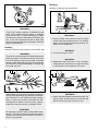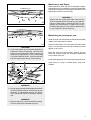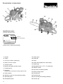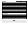
1
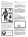
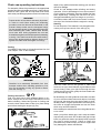
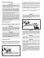
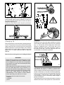
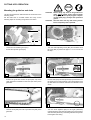
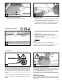
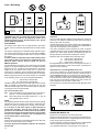
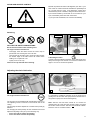
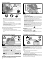
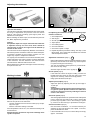
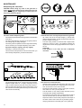
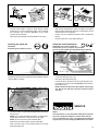
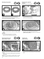
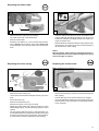
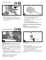
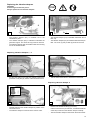
Owner’s and
Safety Manual
for Gasoline Chain Saws (pages 2 - 32)
Manuel d’emploi
et de sécurité
de tronçonneuses thermiques (pages 33 - 63)
DCS 9010
WARNING!
Read and understand this Owner’s and Safety Manual. Always follow safety precautions in the
Owner’s and Safety Manual. Improper use can cause serious injury!
The engine exhaust from this product contains chemicals known to the State of California to cause
cancer, birth defects or other reproductive harm. Preserve this Manual carefully!
ATTENTION!
Suivez toujours les conseils de sécurité du présent manuel d’emploi et de sécurité.
Une utilisation incorrecte de la tronçonneuse peut entraîner des blessures graves!
Conservez avec soin ce manuel!
Les gaz d’échappement émis par ce produit contiennent des produits chimiques connus par l’Etat de
Californie pour provoquer le cancer, des défauts de naissance ou autres dommages de reproduction.
Lisez et comprenez ce manuel.
1
WARNING !
Careless or improper use of this product can cause serious or even fatal injury.
Before operating a chain saw or other MAKITA products it is important that you read, fully understand and
carefully follow the instructions outlined in this manual. Kickback may cause severe or fatal injury and is one of
many potential dangers in operating a chain saw. Kickback and other safety related precautions are described
in detail within this manual. Additional manuals are available from MAKITA U.S.A., INC., 14930-C Northam
Street, La Mirada, CA 90638-5753, USA, Telephone: (714) 522 80 88 and MAKITA CANADA INC.,1950 Forbes
Street, Whitby, Ontario, L1N 7B7, Canada, Telephone: (905) 571 22 00.
This product complies with: American National Standard Institute B 175.1-1991 chain saw safety standard.
Canadian Standards Association Z62.1-95 chain saw safety standard.
Society of Automotive Engineers
SAEJ 335-Jun 95 „Multiposition small engine exhaust system fire ignition
suppression”
With the purchase of this chain saw you have chosen a German quality product. Important instructions for the
assembly and operation of this saw are given in this manual. For your own safety, we ask you to read the accident
prevention instructions very carefully before putting your chain saw into operation, as incorrect handling can,
despite all precautions, lead to accidents. With a little care and attention you will have good service and lasting
satisfaction from this first-rate product. The following industrial property rights apply: US 5411382,
EP 0440827, EP0560201, GBM 8909508, GBM 8913638, GBM 9203378.
MAKITA DCS 9010
Contents
Page
Page
Packing ................................................................................ 2
Delivery inventory ............................................................... 3
Symbols ............................................................................... 3
SAFETY PRECAUTIONS ............................................... 4-15
Denomination of components ......................................... 16
Technical data ................................................................... 17
PUTTING INTO OPERATION ...................................... 18-23
Mounting the guide bar and saw chain ............................... 18
Tightening the saw chain .................................................... 19
Chain brake ......................................................................... 19
Fuels / Refuelling ................................................................ 20
Adjusting the chain lubrication ............................................ 21
Starting and stopping the engine ........................................ 22
Checking the chain brake ................................................... 22
Checking the chain lubrication ............................................ 22
Adjusting the carburetor .................................................. 23
Working in winter .............................................................. 23
MAINTENANCE ............................................................ 24-30
Sharpening the saw chain ............................................. 24-25
Cleaning the guide bar ........................................................ 25
Cleaning the chain brake band ........................................... 25
Checking and replacing the sprocket .................................. 26
Replacing / cleaning the spark arrester screen ................... 26
Checking the muffler screws ............................................... 26
Replacing the starter cable ................................................. 27
Replacing the return spring ................................................. 27
Replacing the suction head ................................................. 27
Cleaning the air filter ........................................................... 28
Replacing the spark plug ..................................................... 28
Replacing the vibration damper .......................................... 29
Instructions for periodic maintenance ................................. 30
Service, spare parts and guarantee .......................... 30-31
Troubleshooting ................................................................ 31
Extract from spare parts list ............................................ 32
Adress list .......................................................................... 64
The MAKITA DCS 9010 will be delivered in a protective cardboard box to prevent transport damage. Cardboard
is a basic raw material and is consequently reuseable or suitable for recycling (waste paper recycling).
RE Y
2
Delivery inventory
1
2
3
1
2
3
4
5
6
7
8
Chain saw
Saw chain
5
Guide bar
Chain protection cover
Universal wrench
Wrench
Screw driver for carburetor adjustment
Owner’s and Safety Manual (not shown)
4
6
7
In case one of the parts listed should not be included in the
delivery inventory, please consult your sales agent.
Symbols
You will notice the following symbols on the chain saw and in the Owner’s and Safety Manual:
Read Owner’s and Safety
Manual and follow the warning
and safety precautions!
STOP
Stop engine!
Particular care and caution!
Wear protective gloves!
Forbidden!
Chain brake
Wear protective helmet, eye and
ear protection!
Caution, kickback!
No smoking!
Fuel and oil mixture
No open fire!
Carburetor adjustment
On/Off (I/O) switch
Chain oil fill/oil pump
Press starting valve
Working in winter
Engine - manual start
First aid
2
1
Choke lever
RE Y
Recycling
Further
symbols
see page 5.
3
Safety precautions for chain saw operators
Additional safety precautions
While operating the chain saw please observe the
following rules:
a)
Contact of the guide bar nose with any object
should be avoided.
b)
Tip contact may cause the guide bar to move
suddenly upward and backward, which may
cause serious or fatal injury.
c)
Always operate the chain saw with both hands.
The following additional safety precautions should be
observed by all users of chain saws:
1. Do not operate a chain saw when you are fatigued.
WARNING!
3. Use caution when handling fuel. Move the chain
saw at least 10 feet (3 m) from the fueling point
before starting the engine.
Read and follow all safety precautions in the
Instruction Manual. Failure to follow instructions
could result in serious injury. It is recommended to
lend the chain saw only to people who are
experienced in working with chain saws. Always
hand over the Owner’s and Safety Manual.
4. Do not allow other persons to be near the chain
saw when starting or cutting with the chain saw.
Keep bystanders and animals out of the work
area.
WARNING!
This chain saw is capable of severe kickback that
could result in serious injury to the operator. Do not
operate this chain saw unless you have
extraordinary cutting needs and experience in and
special training for dealing with kickback. Chain
saws with significantly reduced kickback potential
are available.
6. Keep all parts of your body away from the saw
chain when the engine is running.
WARNING!
Kickback may occur when the nose or tip of the
guide bar touches an object, or when the wood
closes in and pinches the saw chain in the cut. This
contact may abruptly stop the saw chain and in
some cases may cause a lightning fast reverse
reaction, kicking the guide bar up and back towards
the user, or push the guide bar back towards the
operator. Kickback may cause you to lose control
of the saw.
As a chain saw user, you can take several steps to
reduce the risk of a kickback and potential injury.
A. With a basic understanding of kickback, you
can reduce or eliminate the element of surprise.
It is a sudden surprise that contributes to
accidents.
B. Keep a good firm grip on the saw with both
hands, your right hand on the rear grip and
your left hand on the tubular handle, when the
engine is running. Use a firm grip with thumbs
and fingers encircling the chain saw handles.
A firm grip can neutralize kickback and help
you maintain control of the saw. Don’t let go!
C. Make sure that the area in which you are
cutting is free from obstructions. Do not let the
nose of the guide bar contact the log, branch,
or any other obstructions which could be hit
while you are operating the saw.
D. Do not overreach or cut above shoulder height.
E. Follow manufacturer’s sharpening and maintenance instructions for the saw chain.
F. Only use replacement bars and chains specified by the manufacturer or the equivalent.
4
2. Use safety footwear; snug-fitting clothing;
protective gloves; and eye, hearing, and head
protection devices.
5. Do not start cutting until you have a clear work
area, secure footing, and a planned retreat path
from the falling tree.
7. Before you start the engine, make sure that the
saw chain is not contacting anything.
8. Carry the chain saw with the engine stopped, the
guide bar and saw chain to the rear, and the
muffler away from your body.
9. Do not operate a chain saw that is damaged, is
improperly adjusted, or is not completely and
securely assembled. Be sure that the saw chain
stops moving when the throttle control trigger is
released.
10. Shut off the engine before setting it down.
11. Use extreme caution when cutting small size
brush and saplings because slender material may
catch the saw chain and be whipped toward y o u
or pull you off balance.
12. When cutting a limb that is under tension be alert
for springback so that you will not be struck when
the tension on the wood fibers is released.
13. Keep the handles dry, clean, and free of oil or fuel
mixture.
14. Operate the chain saw only in well-ventilated
areas.
15. Do not operate a chain saw in a tree unless you
have been specifically trained to do so.
16. All chain saw service, other than the items listed in
the Owner’s Manual maintenance instructions,
should be performed by MAKITA . (For example,
if improper tools are used to remove the flywheel
or if an improper tool is used to hold the flywheel
in order to remove the clutch structural damage to
the flywheel could occur and could subsequently
cause the flywheel to burst.)
17. When transporting your chain saw, use the chain
protection cover.
18. Low kickback bars and low kickback chains are
designed to reduce the risk of kickback injury. Ask
your MAKITA dealer about these devices.
General Safety Precautions
Contact of the guide bar tip with
any object should be avoided!
Tip contact may cause the guide
bar to move suddenly upward
and backward, which may cause
serious injury!
The use of any chain saw may be hazardous. At full
throttle chain speed can reach 45 mph (20 m/s). It is
important that you read; fully understand and observe
the following safety precautions and warnings. Read
the Owner’s Manual and the safety instructions
periodically.
Always use two hands when
operating the chain saw!
WARNING !
Reactive forces, including kickback, can be dangerous. Careless or improper use of any chain saw
may cause serious or fatal injury.
Have your MAKITA dealer show you how to operate
your chain saw. Observe all applicable local safety
regulations, standards and ordinances.
1
The operator
Physical Condition
You must be in good physical condition and mental
health and not under the influence of any substance
(drugs, alcohol), which might impair vision, dexterity
or judgment.
WARNING!
Minors should never be allowed to use a chain
saw.
Bystanders, especially children and animals should
not be allowed in the area where a chain saw is in
use (fig. 1).
Never let the saw run unattended.
Store it in a locked place away from children. Fill
the fuel tank to 7/8 th full (see storing the saw).
Do not lend your chain saw without this Owner’
Manual. Be sure that anyone using your saw understands the information given.
Proper use of a chain saw involves
1. the operator
2. the saw
3. the use of the saw.
Discription of symbols used on chain
saws:
Z 62.1-95
Class 1A
ANSI B175.1-1991
2
WARNING !
Prolonged use of chain saws exposing the operator
to vibrations may produce Whitefinger disease (Raynaud’s phenomenon). This phenomenon reduces
the hand’s ability to feel and regulate temperature,
produces numbness and burning sensations and
may cause nerve and circulation damage and
tissue necrosis.
All MAKITA saws are therefore provided with an
antivibration system which is essential for those
using chain saws on a regular or sustained basis.
Antivibration systems do not guarantee that you will
not sustain Whitefinger disesase, however, they
reduce this danger considerably. Nevertheless,
continual and regular users should observe their
hands and fingers and in case of any abnormal
symptoms, seek medical advice immediately.
Compliance with
CSA -Standards
Compliance with
ANSI -Standards
5
Proper clothing
The saw
Clothing must be sturdy and snug-fitting, but allow
complete freedom of movement. Avoid loose-fitting
jackets, scarfs, neckties, jewelry, flared or cuffed
pants, or anything that could become entangled with
the saw or brush. Wear overalls or jeans with a
reinforced cutting resistant insert (fig. 3).
Parts of the chain saw: illustrations and description of
parts see page 16.
Protect your hands with gloves when handling saw
and saw chain. Heavy-duty, nonslip gloves improve
your grip and protect your hands.
WARNING !
Never modify a chain saw in any way. Only
attachments supplied by MAKITA or expressly
approved by MAKITA for use with the specific saw
are authorized.
WARNING !
Bow guide bars substantially increase the potential
for kickback and severe or fatal injury due to the
greater kickback zone of the bow design. Bow
guide bars are not recommended for use on
MAKITA chain saws nor are they approved by the
ANSI B 175.1-1991 chain saw safety standard.
The use of the saw
Transporting the chain saw
WARNING!
Always stop the engine before putting a chain saw
down or carrying it. Carrying a chain saw with the
engine running is extremely dangerous. Accidental
acceleration of the engine can cause the chain to
rotate.
Avoid touching the hot muffler.
3
Good footing is most important in chain saw work.
Wear sturdy boots with nonslip soles. Steel-toed safety
boots are recommended.
Proper eye protection is a must. Non-fogging, vented
goggles and a face screen is recommended. Their
use reduces the risk of eye and facial injury.
Wear an approved safety hard hat to protect your
head. Chain saw noise may damage your hearing.
Always wear noise protection equipment (ear plugs
or ear muffs) to protect your hearing.
Continual and regular users should have their
hearing checked regularly.
Wear protective helmet,
eye and ear protection!
6
4
By hand: When carrying your saw by hand, the
engine must be stopped and the saw must be in
the proper position.
The chain protection cover should be over the
chain and the guide bar must point backwards.
When carrying your saw the bar should be behind
you (fig. 4).
By vehicle: When transporting in a vehicle, keep
chain and bar covered with the chain guard. Properly
secure your saw to prevent turnover, fuel spillage
and damage to the saw. Make sure the saw in not
exposed to heat or sparks.
Chain saw operating instructions
For assembly follow the procedure in the appropriate
section "Mounting Guide Bar and Chain" of this manual.
MAKITA chain, guide bar and sprocket must match
each other (see the appropriate section in this manual).
WARNING!
Proper tension of the chain is extremely important.
In order to avoid false setting the tensioning
procedure must be followed as described in this
manual. Always make sure the hexagonal nut(s)
for the sprocket guard is (are) tightened securely
after tensioning the chain. Check chain tension
once more after having tightened the nuts and
thereafter at regular intervals (always before starting
to work). If the chain becomes loose while cutting,
shut off the engine and then tighten. Never try to
tighten the chain while the engine is running!
Wipe off any spilled fuel before starting your saw and
check for leakage.
Check for fuel leakage while refueling and during
operation. If fuel or oil leakage is found, do not start or
run the engine until leak is fixed and spilled fuel has
been wiped away. Clothing with fuel on it has to be
changed immediately (this is a danger to your life!).
Avoid skin contact with fuel. Never loosen or remove
the cap of the fuel tank while the engine is running.
Starting
Do not drop start. This method is very dangerous because you may lose control of the saw (fig. 6).
Fueling
Your MAKITA saw uses on oil-gasoline mixture for fuel
(see chapter "Fuel" of this manual).
6
5
6a
WARNING!
Gasoline is an extremely flammable fuel. Use
extreme caution when handling gasoline or fuel
mix. Do not smoke or bring any sparks or flame
near the fuel (fig. 5).
Fueling instructions
Fuel your chain saw in well ventilated areas or outdoors. Always shut off the engine and allow it to cool
before refueling. Select bare ground for fueling and
move the chain saw at least 10 feet (3 m) from fueling
spot before starting the engine (fig. 5a).
10 feet
5a
Place the chain saw on firm ground or other solid
surface in an open area. Maintain a good balance and
secure footing. Place your right foot through the rear
handle opening and firmly grasp the front handle with
your left hand (fig. 6a).
Be absolutely sure that guide bar and chain are clear
of you or all other obstructions and objects, including
the ground, because when the engine starts in semithrottle position, engine speed will be fast enough for
the clutch to engage the sprocket and turn the chain
which may cause a kickback.
Never attempt to start the saw when the guide bar is in
a cut or kerf.
When you pull the starter grip, don’t wrap the starter
rope around your hands. Do not allow the grip to snap
back, but guide the starter rope slowly back to permit
the rope to rewind properly. Failure to follow this
procedure may result in injury to hand or fingers and
may damage the starter mechanism.
7
Important adjustments
WARNING!
At correct idle speed, chain should not turn. For
directions to adjust idle speed, see the appropriate
section of this Owner’s Manual.
Do not use a saw with incorrect idle speed adjustment. Adjust the idle speed yourself according to
the appropriate section of this Owner’s Manual.
Wrap your fingers tightly around the handles, keeping
the handles cradled between your thumb and
forefinger (fig. 7). With your hands in this position, you
can best oppose and absorb the push, pull and kickback forces of your saw without having it slip out of
your grip (see section of reactive forces). Make sure
your chain saw handle and grip are in good condition
and free of moisture, pitch, oil or grease.
Always start a cut with the chain running at full speed
and the spike bar in contact with the wood.
Have your MAKITA dealer check your saw and
make proper adjustments or repairs.
WARNING!
Check the saw chain tension frequently, especially
just after installing a new chain. New chains may
stretch more during their initial use. A properly adjusted saw chain can be pulled freely around the
guide bar by hand without sagging. Always stop
the engine and wear gloves when checking or
adjusting the chain tension.
Never use the saw with one hand. You cannot
control reactive forces (see pages 9 to 11) and
may lose control of the saw.
Working conditions
Operate your chain saw only outdoors. Operate the
saw under good visibility and daylight conditions only.
WARNING!
Take extreme care in wet and freezing weather
(rain, snow, ice). Put off the work when the weather
is windy, stormy or rainfall is heavy. Clear the area
where you are working.
WARNING!
Avoid stumbling on obstacles such as stumps,
roots or rocks and watch out for holes or ditches.
Be extremely cautious when working on slopes or
uneven ground. There is increased danger of slipping on freshly debarked logs.
Cutting instructions
8
WARNING!
Do not operate your chain saw in semi-throttle
position. Cutting in this position does not permit
the operator proper control of the saw or chain
speed.
WARNING!
Never come too close to a rotating chain with your
hands or body.
WARNING!
Always hold the saw firmly with both hands when the
engine is running. Place your left hand on the tubular
handle and your right hand on grip and throttle lever.
Left-handers should follow these instructions too.
Do not cut any material other than wood or
wooden objects.
Use your chain saw for cutting only. It is not
designed for prying or shoveling away limbs, roots
or other objects.
When sawing, make sure that the saw chain does
not touch any foreign materials such as rocks,
nails and the like (fig. 8). Such objects may be flung
off, damage the saw chain or cause the saw to
kickback.
7
8
9
In order to keep control of your saw, always maintain
a firm foothold. Never work on a ladder, in a tree or on
any other insecure support. Never use the saw above
shoulder height (fig. 9).
Position the chain saw in such a way that your body is
10
clear of the cutting attachment whenever the engine
is running (fig. 10).
Don’t put pressure on the saw when reaching the end
of a cut. The pressure may cause the bar and rotating
chain to pop out of the cut or kerf, go out of control and
strike the operator or some other object. If the rotating
chain strikes some other object a reactive force (see
pages 10 to 12 ) may cause the chain to strike the
operator.
11
Kickback:
Kickback occurs when the upper quadrant of the bar
nose contacts a solid object in the wood or is pinched
(fig. 11). The reaction of the cutting force of the chain
causes a rotational force of the chain saw in the
direction opposite to the chain movement, mainly in
the plane of the bar. This may fling the bar in an
uncontrolled arc towards the operator.
Reactive forces during the cut, including kickback
WARNING!
Reactive forces, that may occur during any cut are
kickback, pushback and pull-in. Reactive forces
can be dangerous! In any chain saw, the powerful
force used to cut wood can be reversed (and work
against the operator).
If the rotating chain is suddenly stopped by contact
with any solid object like a log or branch or is
pinched, the reactive forces instantly occur. These
reactive forces may result in loss of control which
may, in turn, cause serious or fatal injury. An
understanding of the causes of these reactive
forces may help you avoid loss of control.
The most common reactive forces are
- kickback,
- pushback,
- pull-in.
12
This reaction can occur in a fraction of a second and
under some circumstances, cause the guide bar and
chain to strike the operator with enough force to cause
severe or fatal injury. It may also occur during limbing.
It also occurs when the nose of the guide bar is pinched
unexpectedly, unintentionally contacts solid material
in the wood (fig.12) or is incorrectly used to begin a
plunge or boring cut.
The greater the force of the kickback reaction, the more
difficult it becomes for the operator to control the saw.
9
Many factors influence the occurence and force of
the kickback reaction. The type of bar and saw chain
you use is a factor in the force of the kickback reaction.
The speed of contact at which the cutter contacts
the object.
Kickback force increase with the rate of impact.
The contact angle between the nose of the bar
and the foreign object (fig. 11).
Kickback is most pronounced in the upper quadrant
of the bar nose.
MAKITA chain types are designed to reduce kickback
forces.
The depth gauges:
Improper lowering of the depth gauges also increases
the risk of a kickback.
Saw chain cutter sharpness:
WARNING!
A dull improperly sharpened chain may increase
the risk of kickback. Always cut with a properly
sharpened chain.
13
To avoid kickback
The best protection from personal-injury that may
result from kickback is to avoid kickback situations:
1. Hold the chain saw firmly with both hands and
maintain a secure grip.
2. Be aware of the location of the guide bar nose at
all times.
3. Never bring the nose of the guide bar in contact
with any object. Do not cut limbs with the nose of
the guide bar. Be especially careful with small,
tough limbs, small size brush and saplings which
may easily catch the chain.
Devices for reducing the risk of kickback injury
4. Don’t overreach.
MAKITA have developed a special chain brake to
reduce the risk of kickbacks.
5. Don’t cut above shoulder height.
This chain brake increases the safety factor on the
job, e.g. when the saw suddenly kicks upwards the
chain stops rotating within a fraction of a second. A
deflection guard on the disengaging lever of the chain
brake and a loop rear handle ensure that the operator’s hands are fully protected at all times.
6. Begin cutting and continue at full throttle.
Kickback tendency increases as the radius or size of
the guide bar nose increases. MAKITA have developed guide bars with small nose radius, to reduce the
kickback tendency.
9. Do not attempt plunge cuts (see page 13) if you
are not experienced with these cutting techniques.
7. Cut only one log at a time.
8. Use extreme caution when re-entering a previous
cut.
10. Be alert for shifting of the log or other forces that
may cause the cut to close and pinch the chain.
WARNING!
No chain brake prevents kickback.
These brakes are designed only to stop the chain,
if activated.
To ensure a proper operation of the chain brake, it
must be properly maintained. Furthermore, there
must be a sufficient distance between the operator
and the bar to ensure that the chain brake has
sufficient time to activate and stop the chain before
potential contact with the operator.
10
11. Maintain saw chain properly. Cut with a correctly
sharpened, properly tensioned chain at all times.
12. Stand to the side of the cutting path of the chain
saw.
Pushback:
To avoid pull-in
Pushback occurs when the chain on the top of the bar
is suddenly stopped when it is pinched, caught or
encounters a foreign object in the wood. The reaction
of the chain drives the saw straight back toward the
operator causing loss of saw control. Pushback frequently occurs when the top of the bar is used for
cutting (fig. 14).
1. Always start a cut with the chain rotating at full
speed and the spike bar in contact with the wood.
2. Pull-in may also be prevented by using plastic
wedges to open the kerf or cut.
Cutting techniques
Felling
Felling is cutting down a tree.
Before felling a tree, consider carefully all conditions
which may affect the direction of fall, including:
14
To avoid pushback
1. Be alert to forces or situations that may cause
material to pinch the top of the chain.
2. Do not cut more than one log at a time.
3. Do not twist the saw when withdrawing the bar
from a plunge cut or under buck cut (figures 25 to
27 and 33, pages 13 and 15), because the chain
can pinch.
Pull-in:
Pull-in occurs when the chain on the bottom of the bar
is suddenly stopped. The chain on the bottom of the
bar stops when it is pinched, caught or encounters a
foreign object in the wood (see fig. 15). The reaction of
the chain pulls the saw forward, causing the operator
to lose control.
The intended direction of the fall.
The neutral lean of the tree.
Any unusually heavy limb structure.
Surrounding trees and obstacles.
The wind direction and speed.
WARNING!
Always observe the general condition of the tree.
Look for decay and rot in the trunk. If it is rotted
inside, it could snap and fall toward the operator
while being cut.
Also look for broken or dead branches which could
vibrate loose and fall on the operator. When felling
on a slope, the operator should stand on the up-hill
side.
Pull-in frequently occurs when the spike bar of the
saw is not held securely against the tree or limb and
when the chain is not rotating at full speed before it
contacts the wood.
16
When felling in the vicinity of roads, railways and
power lines, etc., take extra precautions (see fig.
16). Inform the police, utility company or railway
authority before beginning to cut.
15
WARNING!
Use extreme caution when cutting small size brush
and saplings which may easily catch the chain and
pull you off balance.
11
45°
2 12
First cut
45°
Second cut
= cutting down area
20
17
When felling, maintain a distance of at least 2 1/2 tree
lengths from the nearest person (see fig. 17).
If the tree has large buttress roots, cut into the largest
buttresses vertically first (horizontally next) and remove (fig. 20).
Note:
The noise of your engine may drown any warning call.
Felling instructions:
Direction of fall
21
18
First clear the tree base and work area from interfering limbs and brush and clean its lower portion an
axe (see fig. 18).
Felling cut
1/10∅
Hinge
Felling notch
11/2" (4cm)
1/5∅
22
45°
19
Then, establish a path of escape and remove all
obstacles. This path should be opposite to the planned
direction of the fall of the tree and at a 45° angle (fig.
19). An alternate path must also be selected. Place all
tools and equipment a safe distance away from the
tree, but not on the escape path.
12
Felling notch
Hinge
23
Then, determine the placement of the felling notch
(fig. 21). The felling notch when properly placed determines the direction in which the tree will fall. It is
made perpendicular to the line of fall and should be as
close to the ground as possible. Cut the felling notch
to a depth of about one-fifth to one-fourth of the trunk
diameter (fig. 22). It should be in no case higher than
it is deep. Make the felling notch very carefully.
Begin the felling cut slighty higher than the felling
notch and on the opposite side of the tree (fig. 22).
Then cut horizontally through towards the felling notch.
Apply the chain saw with its spikes directly behind the
uncut portion of wood and cut toward the notch (fig.
23). Leave approximately 1/10 of the tree diameter
uncut! This is the hinge (fig. 23). Do not cut through the
hinge because you could lose control of the direction
of the fall. Drive wedges into the felling cut where
necessary to control the direction of the fall. Wedges
should be of wood, light alloy or plastic - never of steel,
which can cause kickback and damage to the chain.
Plunge-Cut Method
Timber having a diameter more than twice the length
of the guide bar reauires the use of the plunge-cut
method before making the felling cut.
First, cut a large, wide notch. Make a plunge cut in the
center of the notch.
The plunge cut is made with the guide bar nose. Begin
the plunge cut by applying the lower portion of the
guide bar nose to the tree at an angle (fig. 25). Cut until
depth of the kerf is about the same as the width of the
guide bar (fig. 26). Next, align the saw in the direction
Always keep to the side of the falling tree. When the
tree starts to fall, shut off the engine, withdraw the bar
and walk away on the pre-planned escape path.
Watch out for falling limbs.
WARNING!
Be extremely careful with partially fallen trees which
are poorly supported.
When the tree hangs or for some other reason does
not fall completely, set the saw aside and pull the
tree down with a cable winch, block and tackle or
tractor. If you try to cut it down with your saw, you
may be injured.
25
in which the recess is to be cut. With the saw at full
throttle, insert the guide bar in the trunk (fig. 27).
Enlarge the plunge cut as shown in illustration (fig. 28)
Sectioning Method
WARNING!
Felling a tree that has a diameter greater than the
length of the guide bar requires use of either the
sectioning or plunge-cut method. These methods
are extremely dangerous because they involve the
use of the nose of the guide bar and can result in
kickback. Only properly trained professionals
should attempt these techniques.
26
1
27
2
3
24
For the sectioning method (fig. 24) make the first cut
with the guide bar fanning in toward the hinge. Then,
using the bumper spike as a pivot, reposition the saw
for the next cut. Avoid repositioning the saw more than
necessary. When repositioning for the next cut, keep
the guide bar fully engaged in the kerf to keep the
felling cut straight. If the saw begins to pinch, insert a
wedge to open the cut. On the last cut, do not cut
the hinge.
28
13
Bucking
3
Bucking is cutting a log into sections.
2
1
29
WARNING!
There is an extreme danger of kickback at this
point. Extra caution must be taken to maintain
control of the saw. To make the felling cut, follow
the sectioning method described previously (fig.
29). If you are inexperienced with a chain saw
plunge-cutting should not be attempted. Seek the
help of a professional.
31
WARNING!
1. When bucking, do not stand on the log. Make
sure the log will not roll down-hill. If on a slope,
stand on the up-hill side of the log (see fig. 31).
Watch out for rolling logs.
Limbing
Limbing is removing the branches from a fallen tree.
WARNING!
2. Cut only one log at a time.
WARNING!
There is an extreme danger of kickback during the
limbing operation. Do not work with the nose of the
bar. Be extremely cautious and avoid contacting
the log or other limbs with the nose of the guide bar.
Do not stand on a log while limbing it - you may slip
or the log may roll.
WARNING!
3. Shattered wood should be cut very carefully.
Sharp slivers of wood may be caught and flung
in the direction of the operator of the saw.
32
30
Start limbing by leaving the lower limbs to support
the log off the ground (fig. 30). Always cut from the
top of the limb. Do not underbuck freely hanging
limbs. A pinch may result or the limb may fall,
causing loss of control. If a pinch occurs, stop the
engine and remove the saw, by lifting the limb.
WARNING!
Be extremely cautious when cutting limbs under
tension. The limbs could spring back toward the
operator and cause loss of control of the saw or
injury to the operator.
14
WARNING!
4. When cutting small logs, use a sawhorse (fig. 32).
Never permit another person to hold the log.
Never hold the log with your leg or foot.
Maintenance and Repair
Never operate a chain saw that is damaged, improperly adjusted or not completely or securely assembled.
Follow the maintenance and repair instructions in the
appropriate section of this manual.
1. Relieving cut
Pressure side
Tension side
2. Cross cut
WARNING !
33
2. Cross cut
Always stop the engine and make sure that the
chain is stopped before commencing any maintenance or repair work or cleaning the saw. Do not
attempt any maintenance or repair work not described in this manual. Have such work performed
by your MAKITA service shop only.
Tension side
Pressure side
1. Relieving cut
Maintaining and storing the saw
Keep the chain, bar and sprocket clean and lubricated;
replace worn sprockets or chains.
34
WARNING!
5. Logs under strain require special attention to
prevent the saw from pinching. The first cut is
made on the compression side to relieve the
stress on the log (see fig. 33, 34). The bucking
cut is then made as shown. If the saw pinches,
stop the engine and remove it from the log.
Keep the chain sharp. You can spot a dull chain when
easy-to-cut wood becomes hard to cut and burn marks
appear on the wood.
Keep the chain at proper tension. Tighten all nuts,
bolts and screws except the carburetor adjustment
screws after each use.
Keep spark plug and wire connection tight and clean.
Store saws in a high or locked place, away from
children.
35
WARNING!
6. Only properly trained professionals should work
in an area where the logs, limbs and roots are
tangled (i. e. a blowdown area, fig. 35). Working in blowdown areas is extremely hazardous.
WARNING!
7. Drag the logs into a clear area before cutting.
Pull out exposed and cleared logs first.
15
Denomination of components
4
3
5
2
6
7
1
16
8
17
13
12
11 10
9
14
15
18
19
20
21
25
Identification plate
(example model DCS 9010)
24
23
22
DCS 9010
9909 123456
Serial no.
Year of manufacture
Hamburg, Germany
024.100.600
Indicate when ordering spare parts!
1 Handle
13 Hand guard
2 Choke
14 Guide bar
3 Cover for air filter / spark plug
15 Chain
4 Switch for use in winter
16 Hand guard (release for chain brake)
5 Tubular handle
17 Starter grip
6 Muffler with spark arrester screen
18 Adjusting screws „H-T-L” for carburetor
7 Fastening nuts
19 ON/OFF switch
8 Spike bar
20 Stop knob for halfway throttle
(toothed stop for holding saw steady against wood)
9 Chain catcher
21 Safety locking button
22 Throttle lever
10 Adjusting screw for oil pump (bottom side)
23 Fuel tank cap
11 Sprocket guard
24 Fan housing with starting assembly
12 Identification plate
25 Oil tank cap
16
Technical data
Stroke volume
Bore
Stroke
Max. power at speed
Max. torque at speed
Limit speed
Idling speed
Coupling speed
Sound Pressure Level at the operator‘s ear
at full load according to ANSI B 175.1/ CSA Z62.1
Sound Pressure Level at the bystander‘s position
(50ft/15 m distance) according to ANSI B 175.1
Carburetor (diaphragm carburetor)
Ignition system
Spark plug
Electrode gap
or spark plug
Fuel consumption at max. load per ISO 8893
Specific consumption at max. load per ISO 8893
Fuel tank capacity
Chain oil tank capacity
Mixture ratio (fuel/two-stroke oil)
- when using MAKITA oil
- when using other oils
Chain brake
Sprocket pitch
Number of chain sprocket teeth
Chain type (see the Extract from the spare-parts list)
Pitch / Driving element strength
Guide bar, length of a cut
Guide-bar type (see the Extract from the spare-parts list)
Weight (fuel tank empty, without chain and guide bar)
DCS 9010
cu. in (cm3)
inch (mm)
inch (mm)
hp / rpm
ft lb / rpm
rpm
rpm
rpm
db(A)
db(A)
Type
Type
Type
inch (mm)
Type
kg/h
g/kWh
oz (l)
oz (l)
5.5 (90)
2 (52)
1.6 (42)
6.57 / 9,500
4.3 / 6,500
13,500
2,200
3,600
105
80
TILLOTSON HS-295A (LC)
electronic
NGK BPMR 7A
.020 - .030 (0.5 -0.8)
BOSCH WSR-6F
2.3
480
33,8 (1.0)
13,5 (0.4)
inch
Z
50:1
40:1
engages manually or in case of kickback
3/8
7
inch
inch
3/8 / .058
20 - 36
lbs oz
18 lbs 1 oz
WARNING:
This chain saw is capable of severe kickback that coult result in serious injury to the user. Do not operate this chain
saw unless you have extraordinary cutting needs and experience and specialized training for dealing with kickback.
Chain saws with significantly reduced kickback potential are available.
17
PUTTING INTO OPERATION
STOP
Mounting the guide bar and chain
Use the universal wrench delivered with the chain saw for the
following works.
Put the chain saw on a stable surface and carry out the
following steps for mounting the guide bar and chain:
CAUTION: Before doing any work on the guide bar or
chain, always switch off the engine and pull
the plug cap off the spark plug (see "Replacing the spark plug"). Always wear protective
gloves!
CAUTION: Start the chain saw only after having assembled it completely and inspected!
2
4
5
1
B
A
-
Loosen the two fastening nuts (A/1).
-
Pull off the sprocket guard (A/2).
-
Turn the chain adjusting screw (B/4) anti-clockwise until
the pivot (B/5) is positioned approx. 2 cm in front of the
left stop.
6
5
C
-
D
Position the guide bar. Ensure the pivot (B/5, C/5) of the
chain tightener is inserted into the bore (see circle) of the
guide bar.
-
7
Put the chain (D/6) onto the sprocket (D/7) and insert it into
the guide groove of the guide bar. The cutting edges of the
top side of the bar must be oriented in the direction of the
arrow.
6
8
E
-
18
Lead the chain (E/6) around the sprocket nose (E/8) of the
guide bar.
F
-
Turn the chain tightener (B/4) to the right (clockwise)
until the chain is in gear with the guide groove of the bottom
side of the bar (see circle). Press the guide bar with your left
hand against the casing.
4
G
-
2
H
1
Position the sprocket guard (G/2).
Manually tighten the two fastening nuts (G/1).
Checking the chain tension
Tightening the chain
-
Slightly lift the end of the guide bar and turn the chain
adjusting screw (H/4) to the right (clockwise) until the chain
rests against the bottom side of the guide bar.
-
Continue to lift the guide bar end and firmly tighten the two
fastening nuts (G/1) by means of the universal wrench.
-
The tension of the chain is correct if the chain rests against
the bottom side of the guide bar and can still be easily
turned by hand.
-
While doing so the chain brake must be released.
-
Check the chain tension in short intervalls because new
chains tend to elongate.
-
When checking the chain tension the engine must be
switched off.
STOP
NOTE:
I
It is recommended to use 2-3 chains alternatively.
In order to guarantee a uniform wear of the guide bar the bar
should be turned over whenever replacing the chain.
Chain brake
2
1
3
J
K
The DCS 9010 comes with an inertia chain brake as standard
equipment. If kickback occurs due to contact of the guide-bar
tip with wood (see SAFETY PRECAUTIONS, page 9), the
chain brake will stop the chain through inertia if the kickback is
sufficiently strong. The chain will stop within a fraction of a
second.
Actuating the chain brake (blocking)
If the kickback is strong enough the sudden acceleration of
the guide bar combined with the inertia of the hand guard
(K/3) will automatically actuate the chain brake.
When actuating the chain brake manually, press the hand
guard (K/3) with your left hand in the direction of the guide bar
end (arrow 1).
The chain brake is installed to block the saw chain before
starting it and to stop it immediately in case of an emergency.
Releasing the chain brake
Pull the hand guard (K/3) in the direction of the tubular handle
(arrow 2) until it will engage noticeably. Now the chain break
is released.
19
Fuels / Refuelling
50:1
Fuel
+
1.0 Us-gal.
2.5 Us-gal.
A
5.0 Us-gal.
(3.7 l)
(9.4 l)
(18.9 l)
40:1
OIL
OIL
50:1
2.5 floz. (75 cm3)
3
6.4 floz. (189 cm )
3.2 floz. (94 cm3)
8.0 floz. (236 cm3)
3
12.8 floz. (378 cm ) 16.0 floz. (473 cm3)
CAUTION: This saw is powered by mineral-oil products
(gasoline (petrol) and oil). Be especially careful when
handling gasoline (petrol). Avoid all flame or fire. Do not
smoke (explosion hazard).
Fuel mixture
The engine of the chain saw is a high-efficiency two-stroke
engine. It runs on a mixture of gasoline and two-stroke engine
oil.
The engine is designed for unleaded regular gasoline with a
min. octane value of 91 ROZ. In case no such fuel is available,
you can use fuel with a higher octane value. This will not affect
the engine.
In order to obtain an optimum engine output and to protect
your health and the environment use unleaded fuel only.
Gasoline which contens alcohol should not used in
MAKITA products.
For lubricating the engine use a two-stroke engine oil (quality
grade: TC-3), which is added to the fuel. The engine has been
designed for use of MAKITA high-performance two-stroke
engine oil and a mixture ratio of only 50:1 to protect the
environment. In addition, a long service life and reliable operation with a minimum emission of exhaust gases are ensured.
MAKITA high-performance two-stroke engine oil is available
in the following sizes to suit your individual requirements:
1 l
order number 980 008 607
100 ml order number 980 008 606
If MAKITA high-performance two-stroke engine oil is not available, we urgently recommended a mixture ratio of 40:1 with
other two-stroke engine oils, as otherwise optimum operation
of the engine cannot be guaranteed.
The correct mixture ratio:
50:1 when using MAKITA high-performance two-stroke engine oil, i. e. mix 50 parts gasoline with 1 part oil.
40:1 when using other two-stroke engine oils, i. e. mix 40
parts gasoline with 1 part oil.
NOTE:
For preparing the fuel-oil mixture first mix the entire oil quantity
with half of the fuel required, then add the remaining fuel.
Shake the mixture thoroughly before pouring it into the tank.
It is not wise to add more engine oil than specified to
ensure safe operation. This will only result in a higher
production of combustion residues which will pollute the
environment and clog the exhaust channel in the cylinder
as well as the muffler. In addition, fuel consumption will
rise and performance will decrease.
Storage:
Fuel cannot be stored for an unlimited period of time. Buy only
as much as will be consumed in 4 weeks.
Use only approved and marked containers for transport
and storage.
20
B
Chain oil
Use an oil with adhesive additive for lubricating the chain and
guide bar. The adhesive additive prevents the oil from being
flung off the chain too quickly.
We recommend the use of chain oil which is bio-degradable in
order to protect the environment. The use of bio-degradable oil
may even be required by local regulations.
The chain oil BIOTOP sold by MAKITA is made of special
vegetable oils and is 100% bio-degradable. BIOTOP has been
granted the "blue angel" (Blauer Umweltschutz-Engel) for
being particularly environment-friendly (RAL UZ 48).
BIOTOP chain oil is available in the following sizes:
1l
order number 980 008 610
5l
order number 980 008 611
20 l
order number 980 008 613
Bio-degradable oil is stable only for a limited period of time. It
should be used within 2 years from the date of manufacture
(printed on the container).
Important note on bio-degradable chain oils:
If you are not planning to use the saw again for an extended
period of time, empty the oil tank and put in a small amount of
regular engine oil (SAE 30), and then run the saw for a time.
This is necessary to flush out all remaining bio-degradable oil
from the oil tank, oil-feed system, chain and guide bar, as many
such oils tend to leave sticky residues over time, which can
cause damage to the oil pump or other parts.
The next time you use the saw, fill the tank with BIOTOP chain
oil again.
waste oil
C
NEVER USE WASTE OIL
Waste oil is very dangerous for the environment.
Waste oil contains high amounts of carcinogenic substances.
Residues in waste oil result in a high degree of wear and tear
at the oil pump and the sawing device.
In case of damage caused by using waste oil or unappropriate
chain oil the product guarantee will be null and void.
Your salesman will inform you about the use of chain oil.
AVOID SKIN AND EYE CONTACT
Mineral oil products as well as oils degrease your skin. If your
skin comes in contact with these substances repeatedly and
for a longer period of time, it will desiccate. Various skin
deseases may result. In addition, allergic reactions are known.
Eyes can be irritated by contact with oil. If oil comes into your
eyes, immediately wash them with clear water.
If your eyes are still irritated, see a doctor immediately!
D
Refuelling
chain oil
fuel and oil mixture
STOP
FOLLOW THE SAFETY PRECAUTIONS
Be careful and cautious when handling fuels.
The engine must be switched off.
-
Thoroughly clean the tanks around the screw caps to
prevent dirt from entering the fuel or oil tank.
-
Unscrew the cap and fill in fuel or chain oil until it reaches
the bottom edge of the filler socket. Be careful when
refilling. Do not spill fuel or oil.
-
Tightly screw on the cap.
Clean screw cap and tank after refuelling.
E
Lubricating the chain
In order to ensure sufficient lubrication of the chain there must
always be enough oil in the tank. Its contents is sufficient for
approx. 1/2 hour of continuous operation.
Adjusting the chain lubrication
2
3
F
1
G
The engine must be switched off.
STOP
The oil pump can be regulated with the adjusting screw (F/1).
The adjusting screw is mounted on the bottom side of the
casing.
The oil pump has been adjusted to a medium feed quantity by
MAKITA.
To guarantee a troublefree operation of the oil pump the oil
guide groove at the crank case (G/2) and the oil inlet bore in
the guide bar (G/3) must be cleaned regularly.
Note: After the saw has been turned off it is normal for
residual chain oil to drip from the oil feed system, the guide
bar and the chain for a time. This does not constitute a defect!
Place the saw on a suitable surface.
For changing the feed quantity use the universal wrench and
adjust the adjusting screw (F/1) in the following way:
-
turn to the right to reduce the quantity
turn to the left to increase the quantity.
21
Starting the engine
6
2
1
B
A
-
Move at least 3m away from the place where you fuelled the
saw.
-
Ensure to have a safe footing and put the chain saw on the
floor such that the sawing device is con in contact with any
object.
-
Actuating the chain brake (blocking).
-
Put the short-circuiting switch in position "I" (START) (B/1).
-
Hold the tubular handle tightly with one hand and press the
chain saw to the ground.
-
Put your tip-toe in the back hand guard.
-
Press switch (B/6) before starting the engine.
The valve will close automatically after ignition has taken
place.
Now release the chain brake.
Warm start:
- As described in the section above (cold start), but without
actuating the choke (B/2).
Switching off the engine
-
Checking the safety chain brake
4
Cold start:
- Pull the choke (B/2).
- Press the safety switch (B/3).
- Press the throttle lever (B/4) and lock it with the stop button (B/5).
- Slowly pull out the starter cable until you notice a resistance
(the piston is positioned before the top dead centre).
- Now pull out the starter cable with a fast and forceful movement until you hear a first ignition.
Attention: Do not pull out the starter cable more than approx.
50 cm and lead it back by hand.
- Press the choke (B/2) and again pull the starter cable. As soon
as the engine will run, touch the throttle lever (B/4) to disengage the stop button (B/5).
Attention: As soon as the engine is started it must run without
any load to prevent the chain brake from being damaged.
-
When working with a model equipped with a decompression valve observe the following:
3
5
STOP
Put the short-circuiting switch (B/1) in position "O" (STOP).
Checking the chain lubrication
6
D
C
Do not work with the chain saw without first checking the
chain brake!
- Start the engine as described (make sure you have a good
footing, and place the chain saw on the ground in such a
way that the guide bar is free of contact).
- Grasp the tubular handle firmly with one hand and hold the
grip with the other.
- With the engine running at moderate speed, press the hand
guard (C/6) in the direction of the arrow with the back of your
hand until the chain brake engages. The chain should stop
immediately.
- Immediately release the throttle and release the chain
brake.
IMPORTANT: If the chain does not stop immediately when
you test the chain brake, do NOT use the chain saw. Take
the chain saw to a MAKITA service center.
22
Never work with the chain saw when a sufficient chain lubrication is not guaranteed. Otherwise the service life of the sawing
device will be reduced.
Before starting work check the oil level in the tank and the oil
feeding.
Check the oil feed quantity as described below:
-
Start the chain saw.
- Hold the running chain saw approx. 6" (15 cm) above a trunk
or the ground (use an appropriate base).
If the lubrication is sufficient, you will see a light oil trace because
oil will be centrifuged from the sawing device.
Pay attention to the direction the wind is blowing and avoid
unnecessary exposure to the oil spray!
Adjusting the carburetor
E
F
Important information:
The carburetor of this tool is fitted with limiter caps which restrict
the range of adjustment and prevents over-rich mixture
settings. This ensures providing good engine power and
efficient fuel consumption.
For adjusting the carburetor correctly the following steps
must be carried out:
1. Check adjustment
Before installing the limiter caps, the manufacturer performs
the „Basic Adjustment” procedure.
STOP
2. Start engine
3. Set idle speed
Caution:
4. Adjust speed
An optimum output can only be achieved if the carburetor
is adjusted correctly. For this work, which should be
carried out by an expert, the engine must be warmed up
and the air filter clean.
5. Check idling speed
6. Check acceleration
7. Check max. speed or output
8. Repeat adjustment procedure starting with step 3, until
idling speed, max. speed and acceleration are reached
with the adjustment made.
The carburetor has been adjusted by MAKITA on the basis of
atmosheric pressure conditions at sea level. Other atmospheric pressure conditions or the running-in process of a new
engine may require to readjust the carburetor.
It is urgently recommended to use a revolution indicator (order
number 950 233 210) in order to achieve a correct adjustment
of the carburetor. Use the carburetor srew driver and the
universal wrench delivered with the chain saw.
Before adjusting the carburetor the engine must be warmed up
for a period of 3-5 min.
Adjustment instructions (step 1)
STOP
-
Before initial operation make sure that the adjusting screws
(H and L) have not been set in all the way. Limiter caps do
not protect the engine from leaning.
-
Turn the two adjusting screws (H and L) counter-clockwise as far as they will go.
-
Start the engine and let it warm up (step 2).
Set idle speed (step 3)
-
If the chain turns when the engine is idling, unscrew the
throttle-valve stop screw (T) until the chain stops. If the
engine runs unevenly, screw the screw (T) back in.
-
Idling speed should be 2,200 rpm.
Working in winter
Adjust speed (output) (step 4)
-
G
1
Adjust the speed by adjusting the main jet screw (H) to
13,500 rpm.
Caution:
The DCS 9010 is equipped with a speed limiting electronic ignition system. Speeds of more than 13,500 1/min
cannot be achieved, not even by reducing the amount
of fuel in the mixture.
Check idle speed (step 5)
-
In order to prevent carburetor icing in winter, warm air can be
led from the cylinder to the carburetor.
After having adjusted the max. speed ensure the idle speed
is set to 2,200 rpm. (the chain must not turn). Use the idle
jet screw (L) to regulate it. Turn in the screw (L) to speed
up, and turn out the screw (L) to speed down the engine.
-
Use the universal wrench to turn the button (G/1) completely to the right.
Check acceleration (step 6)
-
Now the carburetor heating is actuated.
-
Now check the acceleration, i. e. the time necessary for
speeding up from idle speed to max. speed. To do this,
press the throttle lever hard.
-
If the acceleration is too low, turn out the idle jet screw (L)
approx. 1/8 rotation.
If the temperature is above 0o C, the carburetor heating must
be switched off.
Not following this instruction may result in damage at the
cylinder and piston.
23
MAINTENANCE
Sharpening the saw chain
STOP
CAUTION: Before doing any work on the guide bar or
chain, always switch off the engine and pull the plug cap
off the spark plug (see "Replacing the spark plug"). Always wear protective gloves!
=
A
=
0,65 mm
(.025")
B
The chain needs sharpening when:
Characteristics of a correctly sharpened chain (type 099):
-
The sawdust produced when sawing humid wood looks like
wood flour.
-
-
The chain penetrates the wood only under great pressure.
All cutters must be of the same length (=). Cutters with
different lengths result in a rough running of the chain and
produce cracks in the chain.
-
The cutting edge is visibly damaged.
-
-
The sawing device is pulled to the left or right when sawing.
This is caused by an unequal sharpening of the chain.
The best cutting results are achieved with a depth limiter
distance of 0.65 mm (.025"). The distance between the
depth limiter and the cutting edge determines the depth of
the cut.
Important: Sharpen regularly, but only slightly.
CAUTION:
If the distance is too wide, the risk of kickbacks
increases.
Generally 2-3 touches are enough.
Have the chain resharpened in a service center when you
have already sharpened it yourself several times.
25°
C
25°
60°
90°
60°
D
-
-
24
The sharpening angle of 25o must be equal for all cutters.
Different angles result in a roughly, irregularly running
chain, increase wear and tear and cause chain ruptures.
The front rake of 60o depends on the cut depth of the round
file. If the file to be used is guided correctly, the correct front
rake results automatically.
E
Files and how to work with them
-
Sharpen using a special file holder with a saw chain round
file. Normal round files are not appropriate for this work.
See "Accessories" for the order number.
-
File the first cutter half with a 7/32" (5,5 mm) dia. round file,
then switch to a 3/16" (4,8 mm) dia. file.
-
The file should cut only when pushed forwards (arrow).
Lift the file when leading it backwards.
-
First sharpen the shortest cutter. The length of this cutter is
then the nominal value for all other cutters of the chain.
-
Replaced cutters must be exactly adopted to the shape of
the other cutters. This is also true for the depth gauges.
-
Always guide the file horizontally (90o to the guide bar).
1/5
25°
25°
F
G
-
The file holder makes it easier to guide the file, carries
markings for a correct sharpening angle of 25o and limits
the cut depth (4/5 of the file diameter). For the order
number see accessories.
-
When filing the markings must be parallel to the chain.
H
-
After having sharpened the chain, the height of the depth
limiter must be checked by means of a chain gauge. For the
order number see accessories.
-
Correct even the smallest projections with a special flat
file (G).
-
Round off the front of the depth limiter (H).
Cleaning the guide bar
Clean the chain brake band
CAUTION:
Protective gloves must be put on.
CAUTION: In any case actuate the
chain brake (blocking) and put on protective
gloves. Do not actuate the chain brake when cleaning.
STOP
4
6
5 3
2
J
I
The bearing surfaces of the guide bar must be regularly cleaned
and checked for damage.
8
1
-
Loosen the fastening nuts (J/1).
-
Pull off the sprocket guard (J/2).
Loosen the screw (J/3) and remove the guide plate (J/4).
Loosen the four screws (J/5) and carefully remove the protective plate (J/6).
NOTE: Ensure the pressure spring (K/8) cannot jump
out. Secure the pressure spring in position before
cleaning.
9
7
SERVICE
K
-
-
Clean the inside, in particular the brake band area (K/7),
with a brush.
NOTE: Do not clean the brake mechanism, in particular the
spring (K/8), because it could jump out of its guide.
NOTE: Do not remove the foam material (K/9).
Remount the protective plate and the guide plate.
After mounting carry out a functional check of the chain
brake (see page 22).
NOTE:
The chain brake is a very important safety device and like
any other component subject to normal wear and tear.
It is recommended to have it checked and maintained
regularly for your own safety by a MAKITA service center.
25
Checking the sprocket
Replacing the sprocket
CAUTION:
Protective gloves must be put on.
2
A
C
B
1
Check the sprocket before mounting a new chain (A).
-
Loosen the fastening nuts (C/1).
Worn out sprockets (more than 0,2 mm) (B) may damage the
new chain and must therefore be replaced.
-
Pull off the sprocket guard (C/2).
4
5
3
D
-
E
Use the universal wrench to remove the locking washer
(D/3).
-
Take off the sprocket (E/5) from the clutch drum.
-
Position the new, slightly oiled sprocket and remount all
parts in the reverse order.
CAUTION:
The locking washer might jump out on removing.
-
Remove the thrust washer (D/4) underneath it.
Checking the
muffler screws
Replacing/cleaning the
spark arrester screen
9
8
6
F
7
The spark arrester screen should be checked and cleaned
regulary.
- Remove the screw (F/6), deflector plate (F/7) and arrester
screen (F/8).
Caution: Do not use sharp or pointed objects for screen
cleaning. Damaged or misformed screen wires may result.
26
G
-
Regularly check the three fastening screws (G/9) for tightness.
Replacing the starter cable
1
H
I
-
Demount the fan housing (H/1) (4 screws).
-
The cable drum must not be demounted.
-
Remove the old cable.
-
Mount the new cable 0.16" x 40" (ø 4x1000 mm) and tie it
up in a simple knot in the drum, and in a knot with a loop
in the starter grip. The end of the cable must not project the
drum.
-
Wind the cable around the drum as far as possible. Then
pull the cable with the starter grip approx. 20" (50 cm) out
of the drum, hold the drum tightly and wind the cable once
again around the drum.
-
Release the drum and let the cable wind up by means of the
spring tension. The starter grip must now stand upright at
the outside of the starter casing.
NOTE:
When the starter cable has been completely pulled out, it
must be possible to turn the cable drum against the spring
tension through 1/4 rotation.
Replacing the suction head
Replacing the return spring
4
2
3
1
5
J
K
1
-
Demount the fan housing (J/1).
-
-
Loosen the screw with the star-shaped recess (J/2) on the
pivot.
Pull the suction head by means of a bent wire through the
tank opening.
-
The felt filter (K/1) of the suction head can be clogged.
-
Pull off the pivot (J/3).
-
-
Remove the cable drum (J/4).
-
Demount the spring cover (J/5) (3 screws).
It is recommended to replace the suction head once every
three months in order to guarantee an unimpeded fuel flow
to the carburetor.
-
Slightly knock the hollow side of the fan housing on wood
while holding it tightly. Thus the old spring will jump out and
release.
-
The new spring is delivered in a box, under full tension. For
mounting the whole box is pressed into the fan housing and
the wire ring is stripped off (a spring which has jumped out
is remounted by turning it clockwise into the housing).
27
Cleaning the air filter
4
3
1
2
A
-
-
B
Demount the filter cover (A/1) (2 screws).
-
Caution: Pull the choke (A/2) to shut the choke shutter and
to prevent dirt particles from entering the carburetor.
Position a screw driver between the two latches and separate the upper and lower part by turning it.
-
Clean the air filter with a soft brush.
-
If the filter is very dirty, clean it in lukewarm soapsuds with
standard detergent.
-
Let the air filter dry completely.
-
Assemble the upper and lower part and put them on the
intake stack. Firmly tighten the screws (A/4).
Loosen the two screws (A/4) and remove the air filter (A/3)
from the intake stack.
If the filter is very dirty, clean it frequently (several times a day),
because only a clean air filter guarantees full engine power.
CAUTION:
Replace damaged air filters immediately.
Torn off pieces of cloth may destruct the engine.
Replacing the spark plug
3
0,5 - 0,8 mm
C
D
.020" - .030"
CAUTION:
Do not touch the spark plug or plug cap if the engine is
running (high voltage).
Switch off the engine before starting any maintenance
work.
Electrode gap
A hot engine can cause burns. Wear protective gloves!
-
The spark plug must be replaced in case of a damage of the
insulating body, consumption of the electrodes or if the elctrodes are very dirty or oily.
Press the loosened spark plug with the firmly connected
ignition cable against the cylinder by means of insulated
pliers (not near the spark plug opening).
-
ON/OFF switch in START position "I".
-
-
Start the engine by forcefully pulling out the starter cable.
Loosen both screws of the filter cover (A/1) and remove
the filter cover (see fig. clean air filter).
-
Pull off the plug cap (C/3) from the spark plug. Only use the
universal wrench delivered with the chain saw for demounting.
-
Mount the new spark plug in the reverse order.
CAUTION: Use only the following spark plugs:
28
NGK BPMR 7A or BOSCH WSR 6F.
The electrode gap must be .020"-.030" (0,5 - 0,8 mm).
Checking the ignition spark
If the function is correct, an ignition spark must be visible near
the electrodes.
Replacing the vibration dampers
CAUTION:
Protective gloves must be put on.
Always replace all five vibration dampers.
STOP
4
5
2
a
1
E
F
3
b
a
-
The vibration damper (E/1) is installed next to the
identification plate.
-
The vibration damper (F/3) is installed underneath the oil
tank cap.
-
The vibration damper (E/2) is installed underneath the
guide bar support. The chain catch (a) must be removed.
-
The vibration damper (F/4) is installed underneath the prefilter. The cover (a) and pre-filter (b) must be removed.
-
The vibration damper (E/5) is installed under the mounting
arm of the tubular handle.
Replacing vibration dampers 1 - 4
4
G
-
Put the saw chain on its side and carefully remove the
protective cover (G/4) by means of the universal wrench.
H
-
Use the offset screw driver to loosen the screw inside.
Replacing vibration damper 5
a
J
I
-
Carefully demount the vibration damper by means of the
universal wrench.
The vibration damper is mounted in the reverse order.
-
Demount the tubular handle (a) (5 screws).
Use the socket wrench (accessories, not delivered with the
chain saw) to demount the vibration damper carefully.
The new vibration damper is mounted in the reverse order.
29
Instructions for daily and periodic maintenance
To ensure long life, prevent damage and ensure the full functioning of the safety features the following maintenance must be
performed regularly. Guarantee claims can be recognized only if this work is performed regularly and properly. Failure to perform
the prescribed maintenance work can lead to accidents!
Perform the following servicing work daily after use. Make a habit of it, it does not require much time and your saw will always function
properly.
Possibly hidden faults can be detected in this manner before causing expensive and annoying interruptions of your work. In case
you should detect a fault in the safety equipment when performing daily servicing, the saw must not be used before elimination of
the fault.
The user of the chain saw must not perform maintenance work which is not described in the Owner’s Manual. All such work must
be carried out by a MAKITA service center.
Page
General work
Chain saw
Sprocket
Chain brake
Before each start
Chain
Guide bar
Chain lubrication
Chain brake
ON/OFF switch,
Safety locking button
Throttle lever
Fuel/oil tank
plug
Clean the outside and check for damage.
In case of any damage have it immediately repaired by a
service center.
Replace in time.
Have it regularly checked by a service center.
Check for damage and sharpness.
Resharpen regularly, replace in time.
Check the chain tension.
Check for damage.
Functional check.
Functional check.
26
24-25
19
21-22
22
Functional check.
22
Check for tightness.
21
Clean.
Check for damage, clean oil intake bore.
Turn it over so that the bearing surfaces are equally worn.
Replace in time.
Clean, in particular the oil guide groove.
Check (chain must not run).
28
21
25
23
Clean to ensure a perfect cooling air supply.
For this the fan housing must be demounted.
27
Carburetor interior and
cylinder ribs
Chain brake
Spark plug
Muffler
Vibration damper
Chain guide
Clean, for this demount cover and protective cover.
Clean the brake band (sawdust, oil)
Check and replace if necessary.
Tighten fastening screws, clean spark arrester screen
Check.
Check.
25
28
26
29
Every 3 months
Suction head
Fuel/Oil tank
Replace.
Clean.
Annually
Chain saw
Check at an authorized service centre
Storage
Guide bar/chain
Demount, clean and oil slightly.
Clean the guide groove of the guide bar.
Empty and clean.
Clean.
Run empty.
Every day
Air filter
Guide bar
Guide bar support
Idling speed
Every week
Fan housing
Fuel/oil tank
Oil pump
Carburetor
27
25
Service, spare parts and guarantee
Maintenance and repair
The maintenance and repair work of modern engines as well as all safety related assemblies require qualified technical training and
the availability of a workshop equipped with special tools and testing devices.
We therefore recommend you to consult a MAKITA service center for the performance of all work not described in this Owner’s
Manual.
The MAKITA service centers are provided with all the necessary equipment and skilled and experienced personnel to work out
correct customer solutions and to advise you in all matters accordingly.
Please contact your nearest service center. Should you however not have an adress for a MAKITA service center then please contact
the MAKITA general trading company (see last page) who will gladly provide you with the adress of your nearest MAKITA
service center.
30
Spare parts
A reliable and continuous operation as well as the safety of your chain saw depend among others on the quality of the spare parts
used. Use only original MAKITA parts, marked
Only original spare parts and accessories guarantee the highest quality in material, accuracy to size and function and safety.
Original spare parts and accessories can be obtained from your local dealer. He will also have the spare part lists to determine the
required spare part numbers, and will be constantly informed about the latest improvements and also about spare part innovations.
Please, take in mind that in case foreign spare parts are used instead of original MAKITA spare parts this will automatically
invalidate the MAKITA product guarantee.
Guarantee
MAKITA guarantees the highest quality and will therefore reimburse all costs for mending through replacement of damaged
parts as a result of material or production faults, which occur within the guarantee time after purchase.
Please, note that in some countries particular guarantee conditions may exist. In case of any doubts, please, contact your salesman
who is responsible for the guarantee of a product.
We ask for your understanding that we cannot accept any responsibility for damage caused by:
• Disregard of the Owner’s Manual.
• Non-performance of the required maintenance and cleaning instructions.
• Wrong carburetor adjustment.
• Normal wear and tear.
• Obvious overload due to permanent excess of the upper limits of capacity.
• Use of guide bars and chains which have not been approved.
• Use of guide bar and chain lengths which have not been approved.
• Use of force, improper use, misuse or accidents.
• Overheating due to dirt on the cylinder ribs and the fan housing.
• Works on the chain saw by unskilled persons or performance of inappropriate repairs.
• Use of unsuitable spare parts or parts which are not original MAKITA parts, as far as they have caused the damage.
• Use of unsuitable or old oil.
• Not tightening external screw connections in time.
• Damage related to conditions arising from lease or rent contracts.
Cleaning, servicing and adjustment works are not covered by the guarantee. All repairs covered by the guarantee are to be
performed by a MAKITA service center.
Troubleshooting
Malfunction
System
Observation
Cause
Chain does not run
Chain brake
Engine runs
Chain brake actuated.
Engine does not start or
only with difficulties
Ignition system
Ignition spark
Malfunction in fuel supply system, compression system, mechanical malfunction.
STOP switch actuated, malfunction or short
circuit in cabling, plug cap, spark plug
or ignition module defective.
Choke in wrong position, carburetor defective,
suction head dirty, fuel line bent or
interrupted.
Cylinder base packing ring defective, radial
shaft packings defective, cylinder or piston
defective
Spark plug does not seal.
Spring in starter broken, broken parts
inside the engine.
No ignition spark
Fuel supply
Fuel tank is filled
Compression
system
Inside
rings
Mechanical
malfunction
Outside
Starter does not engage
Warm start difficulties
Carburetor
Fuel tank is filled
Ignition spark
Wrong carburetor adjustment.
Engine starts, but
dies immediately
Fuel supply
Fuel tank is filled
Wrong idling adjustment, suction head or
carburetor dirty.
Tank venting defective, fuel line interrupted,
cable defective, STOP switch defective,
starting valve dirty.
Insufficient output
Several systems
may be involved
simultanously
Engine is idling
Air filter dirty, wrong carburetor adjustment,
muffler clogged, exhaust channel in cylinder
clogged, spark arrester screen clogged.
No chain lubrication
Oil tank/pump
No oil on the chain
Oil tank empty.
Oil guide groove dirty.
31
Extract from the spare parts list
DCS 9010
Use original MAKITA spare parts only. For performance of repairs and
replacement of other parts your MAKITA service center should be consulted.
3
44
2
45
1
5
46
Pos.
7
1
6
8
2
3
9
11
12
10
5
13
17
18
43
37
19
20
I
0
21
41 42
25
26
30
22(4)
27
23(4)
24(4)
36
50
52
55
53
56
57
51
54
32
28
29
6
7
8
9
10
11
12
13
17
18
19
20
21
22
23
24
25
26
27
28
29
30
36
37
41
42
43
44
45
46
MAKITA No.
443 050 452
443 060 452
443 074 452
443 050 652
443 060 652
528 099 672
528 099 680
528 099 696
952 100 653
952 100 171
024 112 630
122 164 010
965 402 262
020 163 031
024 173 230
965 603 021
010 114 050
963 228 030
024 174 160
024 174 171
915 142 090
965 551 250
965 403 430
965 403 461
913 455 204
965 404 740
024 223 041
962 210 024
119 224 070
001 224 011
927 308 000
024 213 670
923 208 004
963 601 120
965 451 901
963 232 045
024 173 081
941 719 171
940 827 000
944 340 001
Qty. Denomination
1
1
1
1
1
1
1
1
1
1
1
1
1
1
1
1
1
1
1
1
1
1
1
4
4
4
1
1
1
1
1
1
2
1
1
1
1
1
1
1
Solid nose bar 50 cm (20")
Solid nose bar 60 cm (24")
Solid nose bar 74 cm (29")
Sprocket nose bar 50 cm (20")
Sprocket nose bar 60 cm (24")
Saw chain 3/8" for 50 cm (20")
Saw chain 3/8" for 60 cm (24")
Saw chain 3/8" for 74 cm (29")
Chain protection, 20-24"
Chain protection, 29"
Starter device cpl.
Starter cable
Starter grip
Return spring
Air filter (Robkoflok)
Spark plug
Oil tank cap cpl.
O-Ring
Spark arrester screen
Deflector plate
Self-tapping screw
Housing
Vibration damper
Vibration damper
✪ Socket-head-screw
Plug
Clutch drum
Needle cage
Sprocket 3/8", Z=7
Thrust washer
Locking washer
Sprocket guard cpl.
Hexagonal nut
Suction head
Fuel tank cap cpl.
O-Ring
Pre-filter
Universal wrench
Angled screw driver
Carburetor screw driver
Accessories (not delivered with the chain saw)
50 953 100 071 1 Chain gauge
51 953 004 010 1 File handle
52 953 003 040 1 Round file 7/32" dia. (5,5 mm)
52 953 003 070 1 Round file 3/16" dia. (4,8 mm)
53 953 003 060 1 Flat file
54 953 009 000 1 File holder
(with round file 7/32" (5,5 mm))
953 007 000 1 File block for guide bar
55 944 500 860 1 ✪ Screw driver
56 944 500 862 1 ✪ Screw driver 8" (200 mm)
57 944 500 861 1 ✪ Screw driver 4" (100 mm)
944 500 621 1 Socket wrench
(for vibration damper)
949 000 031 1 Combined can
(for 5l fuel, 2,5l chain oil)