1
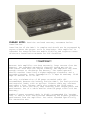
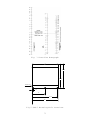
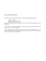
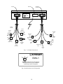
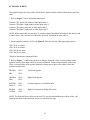
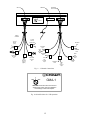
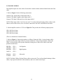
CMA-1
Installation Instructions
1
PLEASE NOTE:
installation.
Read the enclosed warranty statement before
Installation of the CMA-l is complex and should not be attempted by
anyone without the proper tools or knowledge. This amplifier is
intended for state-of-the-art mobile fidelity and requires stateof-the-art installation methods for full benefits.
**CAUTION**
Because this amplifier can draw extremely large current from the
battery, the standard automobile charging system may not be
sufficient. Even With the engine running, the amplifier may draw
enough current to discharge the battery. The owner/operator
should consider installing a higher-amperage alternator and a
secondary battery. Power consumption is 73 amps DC maximum, 10-40
amps DC nominal at 12-14 VDC.
Use only a minimum size of #8 gauge stranded cable (#6
recommended) between the battery and the CMA-l, for both positive
and negative leads, with no splices. Thinner cable may overheat
and cause a fire. Thinner cable also reduces the l2VDC power
available to drive the unit, thus reducing total output power and
performance. Use of a cable smaller than #8 gauge could void the
warranty.
Number 6 gauge stranded cable is highly recommended for lengths
over 12 feet or with installations demanding the highest possible
performance from the amplifier. Use cable intended specifically
for automotive use.
2
Fig. 1 Fuse-Size Nomograph
14 1/2"
13 5/8"
.275 DIA. TYP.
1/2"
8"
15 1/2"
16"
Fig 2 CMA-1 Mounting-Hole Locations
3
**Caution**
It is very important to install a 60-amp fuse in the +12VDC power
wire at the battery. This fuse prevents fires caused by wiring
shorts to the vehicle chassis due to improper installation or
unforeseen accidents.
As in any professional installation, fusing the speaker lines is
highly recommended to protect the speakers. Refer to Figure 1 to
determine proper speaker-fuse values.
If speaker cables must be spliced to shorten or lengthen them, the
splices must be mechanically and electrically sound. Simply
twisting wires together and wrapping with electrical tape is not
adequate. We strongly recommend insulated crimped terminals, wire
nuts wrapped with electrical tape, or solder connections with wire
nuts wrapped with electrical tape.
Avoid pinching or piercing the speaker cable during installation.
Route speaker cables separate from amplifier- input cables to
prevent oscillations. Observe proper polarity of plus and minus
wires when adding wire.
Due to extreme output power, the CMA-1 could, when abused, damage
certain models of loudspeakers. Use speakers that can handle the
amplifier power output. After installation, turn up the volume
slowly and avoid overdriving the speakers.
Accessories Supplied: The CMA-1 comes complete with:
60-amp fuse
Fuse Holder
Input cable harness
Remote on/off cable
Mounting: Mount the CMA-1 securely, say to the vehicle chassis or to a wooden panel. Allow
adequate airspace (at least 1”) and sufficient airflow around the heat fins for cooling. The CMA-1
may be mounted horizontally or vertically in the trunk or behind rear car seats. DO NOT place the
CMA-1 in the engine compartment or in an area exposed to a harsh environment. Do not mount near
the vehicle heater.
Dimensions of the CMA-1 are 16”L x 14-1/2”W x 1-5/8”H. Mounting-hole locations are shown in
Figure 2. The amplifier can be used as a hole template.
4
_
+
60-A Fuse
CAUTION:
THE USE OF WIRE SMALLER
THAN #8 GUAGE COULD
DEGRADE AMPLIFIER
PERFORMANCE
AND CREATE A FIRE HAZARD
_
+
CMA-1
Fig. 3 Power-Wiring Connections
3
4
}
5
CMA-1
Green Wire
CONNECT GREEN
REMOTE WIRE TO:
Fuse Box
Terminal
Controlled
By Key
or
Ignition
or
Tuner/Tape Deck
12V Terminal
Fig. 4 Remote On/Off Wire Connection
5
POWER WIRING: (refer to Figure 3)
1. Before beginning installation, disconnect the Positive (+) battery power cable. Do not reconnect the power cable until installation is complete.
2. Using only the minimum size #8 stranded cable (#6 recommended) with a terminal on the
battery end, connect the CMA-1 terminal marked “-“ to the negative (-) terminal of the
battery. Do not splice the cable. Connecting this cable anywhere other than the battery is
not acceptable (i.e., don’t connect to the vehicle fuse block because the CMA-1 current
draw could melt the vehicle’s wire harness!)
3. Using ONLY the minimum size #8 stranded cable (#6 recommended) with a terminal on the
end, connect the CMA-1 terminal marked “+” to the positive (+) battery cable terminal you
just removed. Do not splice the cable (except for the fuse holder). Connecting this cable
anywhere other than the battery is not acceptable.
If you’re using the same cable for both the positive and negative connections, clearly mark
the positive cable to prevent miswiring. Improper connection could damage the amplifier,
battery or electrical system.
4. Install the supplied 60-amp fuse in the Positive (+) cable near the battery. Failure to install
the fuse could result in vehicle fire due to accidental shorting of the power cables.
REMOTE ON/OFF WIRING (Refer to Figure 4)
1. Turn down your sound system volume to minimum.
2. The green “remote” wire on the CMA-1 is, in effect, the on/off switch of the amplifier.
Connect the green remote wire to the switched +12 VDC supply, either through the ignition
key, the tape deck/tuner, or a switched terminal at the fuse box. Some tuners have a switched
+12v terminal for this purpose.
Do not confuse the green remote wire with the green speaker wire (see Figure 4).
DO NOT connect the green wire to the main +12VDC power supply lead or other
continuously “hot” sources; this will cause the amplifier to be continuously on and will drain
the battery.
3. DO NOT turn on the power until the speaker cables are installed (described later)
6
MULTI-CHANNEL OPTIONS
The CMA-1 has a switch-selectable multi channel format offering the following choices:
3 Channel: 3x100 W
4 Channel: 2x100 W plus 2x50 W
5 Channel: 1x100 W plus 4x50 W
This unusual flexibility allows for 2-channel plus sub woofer, as well as other variations for custom
installations.
NOTE: The CMA-1 inputs are high-impedance line-level inputs. Speaker outputs from the car radio
should NOT be wired into this amplifier.
When connecting tuner/tape deck outputs to the CMA-1 inputs, use an appropriate connector, or
solder the connections and insulate them with electrical tape. All connections must be mechanically
and electrically secure to prevent problems.
7
INPUTS
SPEAKER
OUTPUTS
REMOTE
4
3
}
5
CMA-1
WHITE
CABLES
To CH5
Source
(Subwoofer)
To CH1
Source
(Left Front)
5
4
3
1
BLK
CH1-
2
To CH2
Source
(Right Front)
YEL/RED
CH5-
BLK/WHT
CH1+
1
WHT/RED
CH2+
To CH4
Source
(Right Rear)
5
2
3
To CH3
Source
(Left Rear)
RED/WHT
CH3+
Fig. 5 5-Channel Connections
}
4
3
4
WHT
CH2-
CMA-1
5
CAUTION: Read instruction manual before
operating this switch. Improper installation
could damage vehicle and amplifier.
Fig. 6 Switch Position for 5 CH Operation
8
RED
CH3-
BLU/RED
CH5+
GRN
CH4GRN/YEL
CH4+
5-CHANNEL WIRING
The amplifier inputs are white cables. Each cable is marked with a numbered band at the end of the
cable.
1. Refer to Figure 5 for the following connections:
Connect CH 1 signal (left-front) to white input cable 1.
Connect CH2 signal (right-front) to white input cable 2.
Connect CH3 signal (left-rear) to white input cable 3.
Connect CH4 signal (right-rear) to white input cable 4.
Connect CH5 signal (Subwoofer) to whit input cable 5.
2. Set the amplifier switch to 5 CH as in Figure 6. This provides the following output powers:
CH1: 50 W at 4 ohms
CH2: 50 W at 4 ohms
CH3: 50 W at 4 ohms
CH4: 50 W at 4 ohms
CH5: 100 W at 8 ohms
(These are minimum recommend loads.)
3. Refer to Figure 5. Connect the speakers as follows. Route the CMA-1 colored output cables
separate from its white input cables to prevent oscillations. Using crimp terminals, connect the
CMA-1 colored cables to the speaker terminals, taking care to observe the cables colors and
polarities noted below:
Blk/Wht:
Blk:
CH 1 +
CH 1 -
Left-Front Speaker
Wht/Red:
Wht:
CH 2 +
CH 2 –
Right-Front Speaker
Red/Wht:
Red:
CH 3 +
CH 3 -
Left-Rear Speaker
Grn/Yel:
Grn:
CH 4 +
CH 4 -
Right-Rear Speaker
Blu/Red:
Yel/Red:
CH 5 +
CH 5 -
Subwoofer
9
INPUTS
SPEAKER
OUTPUTS
REMOTE
4
3
}
5
CMA-1
WHITE
CABLES
To CH5
Source
(Right Rear)
To CH1
Source
(Left Front)
YEL/RED
CH4-
5
BLK/WHT
CH1+
1
4
To CH2
Source
(Right Front)
WHT/RED
CH2+
3
To CH3
Source
(Left Rear)
1
BLK
CH1-
2
5
Not
Connected
use wire
nut
BLU/RED
CH4+
2
3
WHT
CH2RED/WHT
CH3+
RED
N/C
Cut and
Tape
Fig. 7 4-Channel Connections
}
4
3
CMA-1
5
CAUTION: Read instruction manual before
operating this switch. Improper installation
could damage vehicle and amplifier.
Fig. 8 Switch Position for 4 CH Operation
10
4
GRN
N/C
Cut and
Tape
GRN/YEL
CH3-
4-CHANNEL WIRING
The amplifier inputs are white cables. Each cable is marked with a numbered band at the end of the
cable.
1. Refer to Figure 7 for the following connections:
Connect CH 1 signal (left-front) to white input cable 1.
Connect CH2 signal (right-front) to white input cable 2.
Connect CH3 signal (left-rear) to white input cable 3.
Connect CH4 signal (right-rear) to white input cable 5.
NOTE: White input cable 4 is not used. To avoid accidental shorting of this cable to the chassis, and
to reduce noise, use a wire nut to connect the “hot lead” and shield in white cable 4.
2. Set the amplifier switch to 4 CH as in Figure 8. This provides the following output powers:
CH1: 50 W at 4 ohms
CH2: 50 W at 4 ohms
CH3: 100 W at 8 ohms
CH4: 100 W at 8 ohms
(These are minimum recommend loads.)
3. Refer to Figure 7. Connect the speakers as follows. Route the CMA-1 colored output cables
separate from its white input cables to prevent oscillations. Using crimp terminals, connect the
CMA-1 colored cables to the speaker terminals, taking care to observe the cables colors and
polarities noted below:
Blk/Wht:
Blk:
CH 1 +
CH 1 -
Left-Front Speaker
Wht/Red:
Wht:
CH 2 +
CH 2 –
Right-Front Speaker
Red/Wht:
Grn/Yel:
CH 3 +
CH 3 +
Left-Rear Speaker or Left Subwoofer
Blu/Red:
Yel/Red:
CH 4 +
CH 4 -
Right–Rear Speaker or Right Subwoofer
NOTE: The Red and Green cables are not used. To avoid accidental shorting of these cables, clip
exposed ends back to the insulation, and cover with electrical tape.
11
INPUTS
SPEAKER
OUTPUTS
REMOTE
4
3
}
5
CMA-1
WHITE
CABLES
To CH3
Source
(Subwoofer)
To CH1
Source
(Left )
YEL/RED
CH3-
5
BLK/WHT
CH1+
1
2
4
Not
Connected
use wire
nut
3
To CH2
Source
(Right)
5
BLK
1
N/C
Cut and
Tape
WHT/RED
CH1-+
Not
Connected
use wire
nut
WHT
N/C
Cut and
Tape
BLU/RED
CH3+
2
3
RED/WHT
CH2+
RED
N/C
Cut and
Tape
Fig. 9 3-Channel Connections
}
4
3
CMA-1
5
CAUTION: Read instruction manual before
operating this switch. Improper installation
could damage vehicle and amplifier.
Fig. 10 Switch Position for 3 CH Operation
12
4
GRN
N/C
Cut and
Tape
GRN/YEL
CH2-
3-CHANNEL WIRING
The amplifier inputs are white cables. Each cable is marked with a numbered band at the end of the
cable.
1. Refer to Figure 9 for the following connections:
Connect CH 1 signal (left) to white input cable 1.
Connect CH2 signal (right) to white input cable 2.
Connect CH3 signal (Subwoofer) to white input cable 5.
NOTE: White input cables 2 and 4 are not used. To avoid accidental shorting of these cables to the
chassis, and to reduce noise, use a wire nut to connect the “hot lead” and shield in each cable.
2. Set the amplifier switch to 3 CH as in Figure 10. This provides the following output powers:
CH1: 100 W at 8 ohms
CH2: 100 W at 8 ohms
CH3: 100 W at 8 ohms
(These are minimum recommend loads.)
3. Refer to Figure 9. Connect the speakers as follows. Route the CMA-1 colored output cables
separate from its white input cables to prevent oscillations. Using crimp terminals, connect the
CMA-1 colored cables to the speaker terminals, taking care to observe the cables colors and
polarities noted below:
Blk/Wht:
Wht/Red:
Red/Wht:
Grn/Yel:
CH 1 +
CH 2 +
CH 2 +
CH 2 +
Left Speaker
Blu/Red:
Yel/Red:
CH 3+
CH 3 -
Subwoofer
Right Speaker
NOTE: The Back, White, Red and Green cables are not used. To avoid accidental shorting of these
cables, clip exposed ends back to the insulation, and cover with electrical tape.
13
OPERATION:
1. After all connections are made, double check all connections to make sure they are
mechanically and electrically sound. Verify correct polarity of all cables.
2. Check that there are no shorts to the vehicle chassis.
3. Check that the CMA-1 input and output cables are routed separate from each other.
4. Connect the positive battery-cable terminal to the battery. This terminal should already have
the CMA-1 positive cable attached to it.
5. The CMA-2 has no level controls to preset. All level adjustment is done at the front end of
the sound system.
6. With your sound system volume turned all the way DOWN, apply power to the CMA-1 by
turning on your ignition key or tape deck/tuner.
7. After the 5-second turn-on delay, slowly turn up the volume, and enjoy your music! Avoid
overdriving the speakers.
TROUBLESHOOTING:
NO SOUND FROM ALL SPEAKERS OR SOME SPEAKERS:
1. Recheck cable connections and routing according to this instruction sheet.
2. Check the fuse in-line with the +12VDC power cable. If the fuse is blown, find and repair the
cable short to the vehicle frame. Replace the fuse with the same value fuse.
DISTORDED (GRITTY) SOUND:
1.
2.
3.
4.
Turn down the volume of your sound system.
Turn down the bass of your sound system.
Turn down the low-frequency control(s) on your graphic equalizer.
Recheck cable connections at the speaker terminals for shorts. Check that the CMA-1 colored
output cables are routed separately from its white input cables.
STATIC (RADIO INTERFERENCE, IGNITION, NOISE):
1.
2.
3.
4.
Recheck all connections.
Use radio-suppressor spark-plug cables.
Use resistor-type spark plugs.
Check that all external equipment such as radios, tape decks, equalizers, and electronic
crossovers have one main ground point.
5. Try to pin point the source of the static, such as the radio, equalizer, crossover or power amp.
Make sure that these units are not defective.
6. Check for proper antenna grounding.
14
7. If the ignition system uses a distributor with points, check the capacitor on the distributor and
also the capacitor on the coil.
8. Try re-routing the input and output cables.
9. Check for a bad alternator.
10. Make sure all power-cable connections are tight and secure.
11. Re-route the power cables.
Service Policies:
Due to the sophisticated circuitry of the CMA-1, only qualified, fully trained technicians should be
allowed to service it.
Specifications:
Output Power: (20Hz-20kHz):
3 Channel Mode:
3x100W @ 8 ohms
.1% THD
4 Channel Mode:
2x50W @ 4 ohms
2x100W @ 8 ohms
.05% THD
.1% THD
5 Channel Mode:
4x50W @ 4 ohms
1x100W @ 8 ohms
.05% THD
.1% THD
Frequency Response
20Hz-20kHz at 1 watt:
THD at 50W
at 100W (Bridged)
S/N Ratio:
Damping Factor
50Hz-1kHz:
Input Sensitivity:
Input Impedance:
Supply Voltage:
Power Consumption:
Size:
Weight:
Rated
Typical
+/- 1dB
.05%
.1%
90dB
+/- .5dB
.04%
.08%
100dB
50
.775V
>10K ohm
12-14 VDC
73 amps DC max.
10-40 amps DC nominal
16”L x 14-1/2”W x 3-5/8”H
20 lbs.
100
# # #
15