1
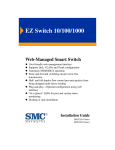
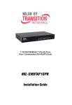
ES4624-SFP/ES4626-SFP L3 Gigabit Ethernet Switch i www.edge-core.com Preface ES4624-SFP/ES4626-SFP L3 Gigabit Ethernet Switch is a high performance routing switch released by Edge-Core that can be deployed as an aggregation device for campus networks, enterprise networks and IP metropolitan networks; as well as core layer switches for small and medium-sized networks. ES4624/26-SFP can seamlessly support various network interfaces from 10Mb, 100Mb, 1000Mb to 10Gb Ethernets. We are providing this manual for your better understanding, using and maintenance of the ES4624/26-SFP. We strongly recommend you to read through this manual carefully before installation and configuration to avoid possible damage to the switch and malfunction. ii Compliances and Safety Warnings FCC - Class A This equipment has been tested and found to comply with the limits for a Class A digital device, pursuant to part 15 of the FCC Rules. These limits are designed to provide reasonable protection against harmful interference when the equipment is operated in a commercial environment. This equipment generates, uses, and can radiate radio frequency energy and, if not installed and used in accordance with the instruction manual, may cause harmful interference to radio communications. Operation of this equipment in a residential area is likely to cause harmful interference in which case the user will be required to correct the interference at his own expense. You are cautioned that changes or modifications not expressly approved by the party responsible for compliance could void your authority to operate the equipment. You may use unshielded twisted-pair (UTP) for RJ-45 connections - Category 3 or better for 10 Mbps connections, Category 5 or better for 100 Mbps connections, Category 5, 5e, or 6 for 1000 Mbps connections. For fiber optic connections, you may use 50/125 or 62.5/ 125 micron multimode fiber or 9/125 micron single-mode fiber. Industry Canada - Class A This digital apparatus does not exceed the Class A limits for radio noise emissions from digital apparatus as set out in the interference-causing equipment standard entitled “Digital Apparatus,” ICES-003 of the Department of Communications. Cet appareil numérique respecte les limites de bruits radioélectriques applicables aux appareils numériques de Classe A prescrites dans la norme sur le matériel brouilleur: “Appareils Numériques,” NMB-003 édictée par le ministère des Communications. Japan VCCI Class A CE Mark Declaration of Conformance for EMI and Safety (EEC) This information technology equipment complies with the requirements of the Council Directive 89/336/EEC on the Approximation of the laws of the Member States relating to Electromagnetic Compatibility and 73/23/EEC for electrical equipment used within certain voltage limits and the Amendment Directive 93/68/EEC. For the evaluation of the compliance with these Directives, the following standards were applied: iii Caution: Do not plug a phone jack connector in the RJ-45 port. This may damage this device. Les raccordeurs ne sont pas utilisés pour le système téléphonique! Safety Compliance iv Please read the following safety information carefully before installing the switch: WARNING: Installation and removal of the unit must be carried out by qualified personnel only. • The unit must be connected to an earthed (grounded) outlet to comply with international safety standards. • Do not connect the unit to an A.C. outlet (power supply) without an earth (ground) connection. • The appliance coupler (the connector to the unit and not the wall plug) must have a configuration for mating with an EN 60320/IEC 320 appliance inlet. • The socket outlet must be near to the unit and easily accessible. You can only remove power from the unit by disconnecting the power cord from the outlet. • This unit operates under SELV (Safety Extra Low Voltage) conditions according to IEC 60950. The conditions are only maintained if the equipment to which it is connected also operates under SELV conditions. France and Peru only This unit cannot be powered from IT† supplies. If your supplies are of IT type, this unit must be powered by 230 V (2P+T) via an isolation transformer ratio 1:1, with the secondary connection point labelled Neutral, connected directly to earth (ground). † Impédance à la terre Power Cord Set U.S.A. and Canada The cord set must be UL-approved and CSA certified. The minimum specifications for the flexible cord are: - No. 18 AWG - not longer than 2 meters, or 16 AWG. - Type SV or SJ - 3-conductor The cord set must have a rated current capacity of at least 10 A The attachment plug must be an earth-grounding type with NEMA 5-15P (15 A, 125 V) or NEMA 6-15P (15 A, 250 V) configuration. Denmark The supply plug must comply with Section 107-2-D1, Standard DK2-1a or DK2-5a. Switzerland The supply plug must comply with SEV/ASE 1011. U.K. The supply plug must comply with BS1363 (3-pin 13 A) and be fitted with a 5 A fuse which complies with BS1362. The mains cord must be <HAR> or <BASEC> marked and be of type HO3VVF3GO.75 (minimum). Europe The supply plug must comply with CEE7/7 (“SCHUKO”). The mains cord must be <HAR> or <BASEC> marked and be of type HO3VVF3GO.75 (minimum). IEC-320 receptacle. v Veuillez lire à fond l'information de la sécurité suivante avant d'installer le Switch: AVERTISSEMENT: L’installation et la dépose de ce groupe doivent être confiés à un personnel qualifié. • Ne branchez pas votre appareil sur une prise secteur (alimentation électrique) lorsqu'il n'y a pas de connexion de mise à la terre (mise à la masse). • Vous devez raccorder ce groupe à une sortie mise à la terre (mise à la masse) afin de respecter les normes internationales de sécurité. • Le coupleur d’appareil (le connecteur du groupe et non pas la prise murale) doit respecter une configuration qui permet un branchement sur une entrée d’appareil EN 60320/IEC 320. • La prise secteur doit se trouver à proximité de l’appareil et son accès doit être facile. Vous ne pouvez mettre l’appareil hors circuit qu’en débranchant son cordon électrique au niveau de cette prise. • L’appareil fonctionne à une tension extrêmement basse de sécurité qui est conforme à la norme IEC 60950. Ces conditions ne sont maintenues que si l’équipement auquel il est raccordé fonctionne dans les mêmes conditions. France et Pérou uniquement: Ce groupe ne peut pas être alimenté par un dispositif à impédance à la terre. Si vos alimentations sont du type impédance à la terre, ce groupe doit être alimenté par une tension de 230 V (2 P+T) par le biais d’un transformateur d’isolement à rapport 1:1, avec un point secondaire de connexion portant l’appellation Neutre et avec raccordement direct à la terre (masse). Cordon électrique - Il doit être agréé dans le pays d’utilisation Etats-Unis Le cordon doit avoir reçu l’homologation des UL et un certificat de la CSA. et Canada: Les spe'cifications minimales pour un cable flexible sont AWG No. 18, ouAWG No. 16 pour un cable de longueur infe'rieure a` 2 me'tres. - type SV ou SJ - 3 conducteurs Le cordon doit être en mesure d’acheminer un courant nominal d’au moins 10 A. La prise femelle de branchement doit être du type à mise à la terre (mise à la masse) et respecter la configuration NEMA 5-15P (15 A, 125 V) ou NEMA 6-15P (15 A, 250 V). Danemark La prise mâle d’alimentation doit respecter la section 107-2 D1 de la norme DK2 1a : ou DK2 5a. Suisse: La prise mâle d’alimentation doit respecter la norme SEV/ASE 1011. Europe La prise secteur doit être conforme aux normes CEE 7/7 (“SCHUKO”) LE cordon secteur doit porter la mention <HAR> ou <BASEC> et doit être de type HO3VVF3GO.75 (minimum). Bitte unbedingt vor dem Einbauen des Switches die folgenden Sicherheitsanweisungen durchlesen: WARNUNG: Die Installation und der Ausbau des Geräts darf nur durch Fachpersonal erfolgen. • Das Gerät sollte nicht an eine ungeerdete Wechselstromsteckdose angeschlossen werden. vi • Das Gerät muß an eine geerdete Steckdose angeschlossen werden, welche die internationalen Sicherheitsnormen erfüllt. • Der Gerätestecker (der Anschluß an das Gerät, nicht der Wandsteckdosenstecker) muß einen gemäß EN 60320/IEC 320 konfigurierten Geräteeingang haben. • Die Netzsteckdose muß in der Nähe des Geräts und leicht zugänglich sein. Die Stromversorgung des Geräts kann nur durch Herausziehen des Gerätenetzkabels aus der Netzsteckdose unterbrochen werden. • Der Betrieb dieses Geräts erfolgt unter den SELV-Bedingungen (Sicherheitskleinstspannung) gemäß IEC 60950. Diese Bedingungen sind nur gegeben, wenn auch die an das Gerät angeschlossenen Geräte unter SELV-Bedingungen betrieben werden. Stromkabel. Dies muss von dem Land, in dem es benutzt wird geprüft werden: Schweiz Dieser Stromstecker muß die SEV/ASE 1011Bestimmungen einhalten. Europe Das Netzkabel muß vom Typ HO3VVF3GO.75 (Mindestanforderung) sein und die Aufschrift <HAR> oder <BASEC> tragen. Der Netzstecker muß die Norm CEE 7/7 erfüllen (”SCHUKO”). Warnings and Cautionary Messages Warning: This product does not contain any serviceable user parts. Warning: Installation and removal of the unit must be carried out by qualified personnel only. Warning: When connecting this device to a power outlet, connect the field ground lead on the tri-pole power plug to a valid earth ground line to prevent electrical hazards. Warning: This switch uses lasers to transmit signals over fiber optic cable. The lasers are compliant with the requirements of a Class 1 Laser Product and are inherently eye safe in normal operation. However, you should never look directly at a transmit port when it is powered on. Caution: Do not plug a phone jack connector in the RJ-45 port. This may damage this device. Les raccordeurs ne sont pas utilisé pour le système téléphonique! Caution: Use only twisted-pair cables with RJ-45 connectors that conform to FCC standards. Caution: Wear an anti-static wrist strap or take other suitable measures to prevent electrostatic discharge when handling this equipment. vii viii Contents PREFACE ................................................................................................ II CONTENTS............................................................................................ IX CHAPTER 1 INTRODUCTION......................................................... 1-1 1.1 PRODUCT BRIEF ............................................................................................... 1-1 1.1.1 Overview ..................................................................................................................... 1-1 1.1.2 Features and Benefits................................................................................................. 1-2 1.2 PHYSICAL SPECIFICATIONS .............................................................................. 1-3 1.3 DESCRIPTION OF HARDWARE .......................................................................... 1-3 1.3.1 Front Panel ................................................................................................................. 1-3 1.3.2 Back Panel .................................................................................................................. 1-4 1.3.3 DC Power Input.......................................................................................................... 1-4 1.3.4 Status LEDs ................................................................................................................ 1-5 1.3.5 Front Panel Port Description .................................................................................... 1-5 CHAPTER 2 HARDWARE INSTALLATION.................................. 2-1 2.1 INSTALLATION NOTICE .................................................................................... 2-1 2.1.1 Environmental Requirements ................................................................................... 2-1 2.1.2 Installation Notice ...................................................................................................... 2-4 2.1.3 Security Warnings...................................................................................................... 2-4 2.2 INSTALLATION PREPARATION .......................................................................... 2-5 2.2.1 Verify the Package Contents...................................................................................... 2-5 2.2.2 Required Tools and Utilities ...................................................................................... 2-5 2.3 INSTALLATION GUIDE ...................................................................................... 2-5 2.3.1 Installing the Switch................................................................................................... 2-5 2.3.2 Connecting Console.................................................................................................... 2-6 2.3.3 SFP Transceiver Installation ..................................................................................... 2-7 2.3.4 XFP Transceiver Installation..................................................................................... 2-7 2.3.5 Copper Cable/Fiber Cable Connection .................................................................... 2-8 2.3.6 Power Supply Connection ......................................................................................... 2-8 ix Chapter 1 Introduction 1.1 Product Brief ES4624/26-SFP series switch include two models: ES4624-SFP and ES4626-SFP. ES4624-SFP: Figure 1-1 ES4624-SFP Switch Figure 1-2 ES4626-SFP Switch ES4626-SFP: 1.1.1 Overview ES4624/26-SFP series switch are 10Gb Ethernet routing switch. ES4624-SFP has 24 fixed 1000Mb ports (16 1000Mb fiber SFP ports and 8 1000Mb COMBO ports). ES4626-SFP has 24 fixed 1000Mb ports (16 1000Mb fiber SFP ports and 8 1000Mb COMBO ports) and 2 fixed 10Gb XFP ports. ES4624/26-SFP series switch are based on 10Gb switching technology. The switches fully support IPv6, whereas their height is only 1U. As distribution layer switches which are 1-1 featured in high performance, small size and flexibility, ES4624/26-SFP series switch with advanced intelligent and secure features, can serve ideally as distribution layer switches for campus networks, enterprise networks and IP metropolitan networks; as well as core layer switches for small and medium-sized networks. 1.1.2 Features and Benefits Various Interfaces ES4624/26-SFP series switch provide 16 fixed 1000Mb fiber SFP ports, 8 1000Mb COMBO ports (1000Mb fiber SFP ports/1000Mb copper ports) and 2 fixed 10Gb XFP ports (ES4626-SFP). Secure Power Supply ES4624/26-SFP series switch provide AC/DC power redundancy. It can be deployed with 100-240V AC power input, -48V DC power input or 100-240V AC power/-48V DC power input simultaneously. Support 10Gb Ethernet 10Gb Ethernet which adopts full-duplex technology instead of low-speed, half-duplex CSMA/CD protocol, is a big leap in the evolution of Ethernet. 10Gb Ethernet can be deployed in star or ring topologies. With 10Gb Ethernet, ES4624/26-SFP series switch provide broad bandwidth and powerful processing capacity. It is suitable for metropolitan networks and wide area networks. Using ES4624/26-SFP series switch, users can simplify network structures and reduce cost of network construction. Networking Protocols ES4624/26-SFP series switch support 802.1d/w/s, 802.1Q, 802.1p, 802.3ad, 802.3x, GVRP, DHCP and SNTP etc. The switches also support comprehensively the multicast protocols such as IGMP, DVMRP and PIM. Moreover, ES4624/26-SFP series switch support RIPv1/2, OSPF and IPv6. All these protocols supported enable ES4624/26-SFP series switch to meet the requirements of complex network constructions. ACL ES4624/26-SFP series switch support comprehensively ACL policies. The traffic can be classified by source/destination IP addresses, source/destination MAC addresses, IP protocols, TCP/UDP, IP precedence, time ranges and ToS. And various policies can be conducted to forward the traffic. By implementing ACL policies, users can filter the virus packets such as “Worm.Blaster”, “Worm.Sasser” and “Red Code” etc. ES4624/26-SFP series switch also support IEEE802.1x port based access authentication, which can be deployed with RADIUS, to ensure the port level security and block illegal users. QoS ES4624/26-SFP series switch fully support DiffServ Module. Users can specify a queue bandwidth on each port. WRR/SP/SWRR scheduling is also supported. ES4624/26-SFP supports 1-2 the port security. Users can deploy trusted CoS, DSCP, IP precedence and port priority. User can also modify packets’ DSCP and COS values. The traffic can be classified by port, VLAN, DSCP, IP precedence and ACL table. User can also modify packets’ DSCP and IP precedence values. Users can specify different bandwidths for voice/data/video to customize different qualities of service. 1.2 Physical Specifications Management Port 1 Mini-USB serial console port AC/DC Power Input AC: 90 ~ 264VAC,47 ~ 63Hz DC: -40 ~ -60Vdc Power Consumption 80W Max Operating Temperature 0°C ~ 50°C Storage Temperature -40°C ~ 70°C Relative Humidity 5% ~ 95%, no condensate Dimension 436mm×44mm×420mm (W * H * D) Weight Approximate 4kg Mean Time Between Failure Min. 80, 000 Hours MTBF 1.3 Description of Hardware 1.3.1 Front Panel ES4624-SFP has 16 1000Mb SFP ports, 8 1000Mb Combo ports (8 RJ-45 and 8 SFP), 1 Console port and 66 LEDs. The front panel of ES4624-SFP is shown below: 1-3 Figure 1-3 Front Panel of ES4624-SFP ES4626-SFP has 16 1000Mb SFP ports, 8 1000Mb Combo ports (8 RJ-45 and 8 SFP), 2 10Gb XFP ports, 1 Console port and 70 LEDs. The front panel of ES4626-SFP is shown below: Figure 1-4 Front Panel of ES4626-SFP 1.3.2 Back Panel There are 1 100-240V AC power receptacle, 1 -48V DC power receptacle and 1 ground connection. Figure 1-5 Back Panel of ES4624/26-SFP 1.3.3 DC Power Input ES4624/26-SFP supports AC/DC power redundancy. -48 DC power’s pin-outs are distributed as below: Figure 1-6 ES4624/26-SFP DC Power Input Pin-outs Distribution DC power has 3 pin-outs: PIN1:V+ DC power positive electrode input PIN2:V- DC power cathode input PIN3:CGND Ground connection 1-4 1.3.4 Status LEDs ES4624/26-SFP includes a display panel and port indications that simplify installation and network troubleshooting. The LEDs, which are located on the front panel for easy viewing, are shown below and described in the following table. Table 1.1 ES4624/26-SFP LEDs LED Panel Symbol Power Indicator Status Description On (Green) Power is operating normally. Off Power is off. On (Green, blink at 1 Hz) System is operating normally. On (Green, blink at 8 Hz) System is loading. On (Red, blink at 8 Hz) System is malfunctioning. On (Green) RJ-45 port is connected. Off RJ-45 port is not connected. Blink (Green) Sending or receiving data On (Green) SFP transceiver is connected. Off SFP transceiver is not connected. Blink (Green) Sending or receiving data On (Green) XFP transceiver is connected. Off XFP transceiver is not connected. Blink (Green) Sending or receiving data PWR Operation indicator RUN RJ-45 Port Indicator Status Indicator On the left Transfer Indicator On the right SFP Port Indicator Status Indicator On the left Transfer Indicator On the right XFP Port Indicator Status Indicator Link Transfer Indicator Act 1.3.5 Front Panel Port Description ES4624/26-SFP provides 16 1000Mb SFP ports and 8 1000Mb Combo ports (8 RJ-45 and 8 SFP). ES4626-SFP also provides 2 10Gb XFP ports. ES4624-SFP and ES4626-SFP support the following SFP transceivers: z ET4201-SX Gigabit SFP MM 850 nm, 500m (SX) 1-5 z ET4201-LX Gigabit SFP SM 1310 nm, 10Km (LX) z ET4201-LHX Gigabit z ET4201-ZX Gigabit SFP SM 1550 nm, z ET4201-RJ45 Gigabit SFP to Copper cable RJ45 SFP SM 1310 nm, 40Km (LHX) 80Km (ZX) ES4626-SFP supports the following XFP transceivers: z ET5302-LR XFP 10G Transceiver 10KM z ET5302-ER XFP 10G Transceiver 40km z ET5302-SR XFP 10G Transceiver 300M 1-6 Chapter 2 Hardware Installation 2.1 Installation Notice To ensure the proper operation of ES4624/26-SFP and your physical security, please read carefully the following installation guide. 2.1.1 Environmental Requirements The switch must be installed in a clean area. Otherwise, the switch may be damaged by electrostatic adherence. Maintain the temperature within 0 to 50 °C and the humidity within 5% to 95%, non-condensing. The switch must be put in a dry and cool place. Leave sufficient spacing around the switch for good air circulation. The switch must work in the right range of power input (AC power: 90 ~ 264V (50Hz), DC power: -40 ~ -60V) The switch must be well grounded in order to avoid ESD damage and physical injury of people. The switch should avoid the sunlight perpendicular incidence. Keep the switch away from heat sources and strong electromagnetic interference sources. The switch must be mounted to a standard 19’’ rack or placed on a clean level desktop. 2.1.1.1 Dust and Particles Dust is harmful to the safe operation of ES4624/26-SFP. Dust can lead to electrostatic adherence, especially likely under low relative humidity, causing poor contact of metal connectors or contacts. Electrostatic adherence will result in not only reduced product lifespan, but also increased chance of communication failures. The recommended value for dust content and particle diameter in the site is shown below: Max Diameter (µm) Max Density (particles/m³) 0.5 1 3 5 1.4×10⁷ 7×10⁵ 2.4×10⁵ 1.3×10⁵ Table 2.1 Environmental Requirements: Dust In addition, salt, acid and sulfide in the air are also harmful to the switch. Such harmful gases will aggravate metal corrosion and the aging of some parts. The site should avoid harmful gases, 2-1 such as SO2, H2S, NO2, NH3 and Cl2, etc. The table below details the threshold value. Gas Average (mg/m³) Max (mg/m³) SO2 0.2 1.5 H2S 0.006 0.03 NO2 0.04 0.15 NH3 0.05 0.15 Cl2 0.01 0.3 Table 2.2 Environmental Requirements: Particles 2.1.1.2 Temperature and Humidity Although the switch is designed to use 4 fans, the site should still maintain a desirable temperature and humidity. High-humidity conditions can cause electrical resistance degradation or even electric leakage, degradation of mechanical properties and corrosion of internal components. Extreme low relative humidity may cause the insulation spacer to contract, making the fastening screw insecure. Furthermore, in dry environments, static electricity is liable to be produced and cause harm to internal circuits. Temperature extremes can cause reduced reliability and premature aging of insulation materials, thus reducing the switch’s working lifespan. In the hot summer, it is recommended to use air-conditioners to cool down the site. And the cold winter, it is recommenced to use heaters. The recommended temperature and humidity is shown below: Temperature: Relative humidity Long term condition Short term condition Long term condition Short term condition 15 ~ 30°C 0 ~ 50°C 40 ~ 65% 10 ~ 95% Table 2.3 Environmental Requirements: Temperature and Humidity Caution! A sample of ambient temperature and humidity should be taken at 1.5m above the floor and 0.4m in front of the switch rack, with no protective panel covering the front and rear of the rack Short term working conditions refer to a maximum of 48 hours of continued operation and an annual cumulative total of less than 15 days. Formidable operation conditions refers to the ambient temperature and relative humidity value that may occur during an air-conditioning system failure, and normal operation conditions should be recovered within 5 hours. 2-2 2.1.1.3 Power Supply Before powering on the power supply, please check the power input to ensure proper grounding of the power supply system. The input source for the switch should be reliable and secure; a voltage adaptor can be used if necessary. The building’s circuit protection system should include in the circuit a fuse or circuit-breaker of no greater than 240 V, 10 A. It is recommended to use a UPS for more reliable power supplying. . Caution! Improper power supply system grounding, extreme fluctuation of the input source, and transients (or spikes) can result in larger error rate, or even hardware damage! 2.1.1.4 Preventing Electrostatic Discharge Damage Static electric discharges can cause damage to internal circuits, even the entire switch. Follow these guidelines for avoiding ESD damage: Ensure proper earth grounding of the device; Perform regular cleaning to reduce dust; Maintain proper temperature and humidity; Always wear an ESD wrist strap and antistatic uniform when in contact with circuit boards. 2.1.1.5 Anti-interference All sources of interference, whether from the device/system itself or the outside environment, will affect operations in various ways, such as capacitive coupling, inductive coupling, electromagnetic radiation, common impedance (including the grounding system) and cables/lines (power cables, signal lines, and output lines). The following should be noted: Precautions should be taken to prevent power source interruptions; Provide the system with a dedicated grounding, rather than sharing the grounding with the electronic equipment or lightning protection devices. Keep away from high power radio transmitters, radar transmitters, and high frequency strong circuit devices. Provide electromagnetic shielding if necessary. 2.1.1.6 Rack Configuration The dimensions of the ES4624/26-SFP are designed to be mounted on a standard 19’’ rack, 2-3 the dimensions are 436mm x 44mm x 420mm (W x H x D). Please ensure good ventilation for the rack. Every device in the rack will generate heat during operation, therefore vent and fans must be provided for an enclosed rack, and devices should not be stacked closely. When mounting devices in an open rack, care should be taken to prevent the rack frame from obstructing the switch ventilation openings. Be sure to check the positioning of the switch after installation to avoid the aforementioned. Caution! If a standard 19’’ rack is not available, the ES4624/26-SFP can be placed on a clean level desktop, leave a clearance of 10mm around the switch for ventilation, and do not place anything on top of the switch. 2.1.2 Installation Notice Read through the installation instruction carefully before operating on the system. Make sure the installation materials and tools are prepared. And make sure the installation site is well prepared. During the installation, users must use the brackets and screws provided in the accessory kit. Users should use the proper tools to perform the installation. Users should always wear antistatic uniform and ESD wrist straps. Users should use standard cables and connecters. After the installation, users should clean the site. Before powering on the switch, users should ensure the switch is well grounded. Users should maintain the switch regularly to extend the lifespan of the switch. 2.1.3 Security Warnings When using SFP transceiver, do not stare directly at the fiber bore when the switch is in operation. Otherwise the laser may hurt your eyes. Do not attempt to conduct the operations which can damage the switch or which can cause physical injury. Do not install, move or disclose the switch and its modules when the switch is in operation. Do not open the switch shell. Do not drop metals into the switch. It can cause short-circuit. Do not touch the power plug and power socket. Do not place the tinder near the switch. Do not configure the switch alone in a dangerous situation, Use standard power sockets which have overload and leakage protection. Inspect and maintain the site and the switch regularly. Have the emergence power switch on the site. In case of emergence, switch off the power immediately. 2-4 2.2 Installation Preparation 2.2.1 Verify the Package Contents Please unpack the shipping package and verify carefully the contents inside. ES4624/26-SFP should include the followings: ITEM No. Part name Number 1 ES4624/26-SFP switch 1 2 AC power cable 1 3 Manual CD 1 4 Console cable 1 5 Chassis bracket 2 6 Bracket screw 4 7 Qualification certificate 1 8 Warranty card 1 Figure 2.4 ES4624/26-SFP Packet Contents Note: The above contents are subject to the received package contents. 2.2.2 Required Tools and Utilities The required tools and utilities are shown below: Cross screwdrivers Flat-blade screwdriver ESD wrist strap Antistatic uniform Caution! Users should prepare the required tools and utilities by themselves. 2.3 Installation Guide 2.3.1 Installing the Switch Please mount ES4624/26-SFP on the 19’’ rack as below: 1. Attach the 2 brackets on the ES4624/26-SFP with screws provided in the accessory kit. 2-5 2. Put the bracket-mounted switch smoothly into a standard 19’’ rack. Fasten the ES4624/26-SFP to the rack with the screws provided. Leave enough space around the switch for good air circulation. Figure 2-1 Rack-mounting ES4624/26-SFP Caution! The brackets are used to fix the switch on the rack. They can’t serve as a bearing. Please place a rack shelf under the switch. Do not place anything on top of the switch. Do not block the blowholes on the switch to ensure the proper operation of the switch. 2.3.2 Connecting Console ES4624/26-SFP provides a Mini-USB serial console port. 2-6 Figure 2-2 Connecting Console to ES4624/26-SFP The connection procedure is listed below: 1. Find the console cable provided in the accessory kit. Attach the Mini-USB end to console port of the switch. 2. Connect the other side of the console cable to a character terminal (PC). 3. Power on the switch and the character terminal. Configure the switch through the character terminal. 2.3.3 SFP Transceiver Installation ES4624/26-SFP provides multiple 1000Mb SFP transceiver slots. The procedure for installing the SFP transceiver is shown below: Step 1: Put on a ESD wrist strap (or antistatic gloves) Step 2: Insert the SFP transceiver to the guide rail inside the fiber interface line card. Do not put the SFP transceiver up-side-down. Step 3: Push the SFP transceiver along the guide rail gently until you feel the transceiver snap into place at the bottom of the line card. Note: the SFP transceiver is hot swappable. Caution! Do not stare directly at the 2 fiber bore in the SFP transceiver when the switch is in operation, otherwise the laser may hurt your eyes. 2.3.4 XFP Transceiver Installation ES4626-SFP has 2 10Gb fiber transceiver slots. The procedure for installing the XFP 10Gb fiber transceiver is shown below: Step 1: put on an ESD wrist strap (or antistatic gloves) Step 2: Insert the XFP transceiver to the guide rail inside the 10Gb line card. Do not to put the XFP transceiver up-side-down. Step 3: Push the XFP transceiver along the guide rail gently until it comes into contact with the front panel of the 10Gb line card. Note: the XFP 10Gb transceiver is hot swappable. Caution! Do not stare directly at the 2 fiber bore in the XFP transceiver when the switch is in operation, otherwise the laser may hurt your eyes. 2-7 2.3.5 Copper Cable/Fiber Cable Connection Copper cables should be connected as below: Step 1: Insert one end of the Ethernet cable to the RJ-45 Ethernet port in the switch copper cable line card; Step 2: Insert the other end of the Ethernet cable to the RJ-45 Ethernet port of some other device; Step 3: Check all status indicators for the corresponding ports; a lighted LED indicates that the link has been established, otherwise the link is not ready and the cable should be examined. Caution! Please verify the sign above the port to ensure using the right port. Connecting to wrong ports might damage the switch. Fiber cables should be connected as below: Step 1: remove the protective plug from the SFP/XFP fiber transceiver bore; Remove the protective cap from one end of the fiber cable. Keep the fiber end clean and neat. Step 2: Attach one end of the fiber cable to the SFP/XFP transceiver, and attach the other end to the transceiver of the corresponding devices. Note: The SFP/XFP transceiver’s TX port should be connected to the RX port of the corresponding device, and vice versa. Step 3: Check the fiber port status indicator, a lighted LED indicates that the link has been established; otherwise the link is not ready and should be examined. Caution! Please verify the sign above the port to ensure using the other ports. Connecting to wrong ports might damage the transceiver or the other ports. When connecting other devices through a fiber cable to the switch, the output power of the fiber cable must not exceed the maximum received power of the corresponding modules. Otherwise, it will damage the switch. Do not stare at the fiber bore when the switch is in operation. That may hurt your eyes. 2.3.6 Power Supply Connection ES4624/26-SFP uses 100-240V AC power supply by default. Please read the power input specification for the detailed information. -48V DC power supply and AC/DC redundancy power input are also supported. AC Power supply connection procedure is described as below: 2-8 Figure 2-3 Attaching power cable to ES4624/26-SFP 1. Insert one end of the power cable provided in the accessory kit into the power source socket (with overload and leakage protection), and the other end to the power socket in the back panel of the switch. 2. Check the power status indicator in the front panel of the switch. The corresponding power indicator should light. ES4624/26-SFP is self-adjustable for the input voltage. As soon as the input voltage is in the range printed on the switch surface, the switch can operate correctly. 3. When the switch is powered on, it executes self-test procedure and startups. Caution! The input voltage must be within the required range, otherwise the switch can be damaged or malfunction. Do not open the switch shell without permission. It can cause physical injury. 2-9