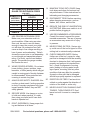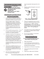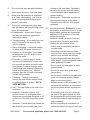
1
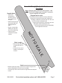
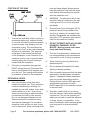
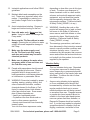
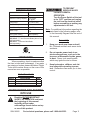
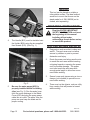
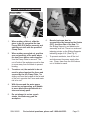
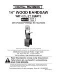
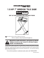
1.5 HP 7” BRIDGE TILE SAW
Model 98265
SET UP AND OPERATING INSTRUCTIONS
Note: Stand (SKU 98328) and Diamond Blade sold separately.
Visit our website at: http://www.harborfreight.com
Read this material before using this product.
Failure to do so can result in serious injury.
SAVE THIS MANUAL.
Copyright© 2008 by Harbor Freight Tools®. All rights reserved. No portion of this manual or any artwork
contained herein may be reproduced in any shape or form without the express written consent of Harbor
Freight Tools. Diagrams within this manual may not be drawn proportionally. Due to continuing improvements, actual product may differ slightly from the product described herein. Tools required for assembly
and service may not be included.
For technical questions or replacement parts, please call 1-800-444-3353.
Manual Revised 10f
CAUTION, without the
safety alert symbol, is
used to address practices not
related to personal injury.
SAVE THIS MANUAL
Keep this manual for the safety warnings
and precautions, assembly, operating, inspection, maintenance and cleaning procedures.
Write the product’s serial number in the back
of the manual near the assembly diagram (or
month and year of purchase if product has no
number). Keep this manual and the receipt in
a safe and dry place for future reference.
IMPORTANT SAFETY
INFORMATION
In this manual, on the labeling, and
all other information provided with
this product:
This is the safety alert symbol. It is used to alert you
to potential personal injury
hazards. Obey all safety messages that follow this symbol
to avoid possible injury or
death.
DANGER indicates a
hazardous situation
which, if not avoided, will result
in death or serious injury.
General Tool Safety Warnings
WARNING Read all safety warnings
and instructions. Failure to follow the
warnings and instructions may result
in electric shock, fire and/or serious
injury.
Save all warnings and instructions
for future reference.
1.
KEEP GUARDS IN PLACE and in working order.
2.
REMOVE ADJUSTING KEYS AND
WRENCHES. Form habit of checking to
see that keys and adjusting wrenches
are removed from tool before turning it
on.
3.
KEEP WORK AREA CLEAN. Cluttered
areas and benches invite accidents.
4.
DON’T USE IN DANGEROUS ENVIRONMENT. Don’t use power tools in
damp or wet locations, or expose them
to rain. Keep work area well lighted.
5.
KEEP CHILDREN AWAY. All visitors
should be kept safe distance from work
area.
6.
MAKE WORKSHOP KID PROOF with
padlocks, master switches, or by removing starter keys.
7.
DON’T FORCE TOOL. It will do the job
better and safer at the rate for which it
was designed.
8.
USE RIGHT TOOL. Don’t force tool or
attachment to do a job for which it was
not designed.
WARNING indicates a
hazardous situation
which, if not avoided, could
result in death or serious injury.
CAUTION, used with
the safety alert
symbol, indicates a hazardous
situation which, if not avoided,
could result in minor or moderate
injury.
NOTICE is used to
address practices not
related to personal injury.
Page 2
For technical questions, please call 1-800-444-3353.
SKU 98265
RECOMMENDED MINIMUM WIRE
GAUGE FOR EXTENSION CORDS
(120 VOLT)
NAMEPLATE
AMPERES
(at full load)
EXTENSION CORD
LENGTH
25’
50’ 100’ 150’
0–6
18
16
16
14
6.1 – 10
18
16
14
12
10.1 – 12
16
16
14
12
12.1 – 16
14
12
Do not use.
TABLE A
9.
USE PROPER EXTENSION CORD.
Make sure your extension cord is in
good condition. When using an extension cord, be sure to use one heavy
enough to carry the current your product will draw. An undersized cord will
cause a drop in line voltage resulting in
loss of power and overheating. Table A
shows the correct size to use depending
on cord length and nameplate ampere
rating. If in doubt, use the next heavier
gauge. The smaller the gauge number,
the heavier the cord.
10. WEAR PROPER APPAREL. Do not wear
loose clothing, gloves, neckties, rings,
bracelets, or other jewelry which may get
caught in moving parts. Nonslip footwear
is recommended. Wear protective hair
covering to contain long hair.
11. ALWAYS USE SAFETY GLASSES. Also
use face or dust mask if cutting operation
is dusty. Everyday eyeglasses only have
impact resistant lenses, they are NOT
safety glasses.
12. SECURE WORK. Use clamps or a vise
to hold work when practical. It’s safer
than using your hand and it frees both
hands to operate tool.
14. MAINTAIN TOOLS WITH CARE. Keep
tools sharp and clean for best and safest performance. Follow instructions for
lubricating and changing accessories.
15. DISCONNECT TOOLS before servicing;
when changing accessories, such as
blades, bits, cutters, and the like.
16. REDUCE THE RISK OF UNINTENTIONAL STARTING. Make sure switch is in off
position before plugging in.
17. USE RECOMMENDED ACCESSORIES.
Consult the owner’s manual for recommended accessories. The use of improper accessories may cause risk of injury
to persons.
18. NEVER STAND ON TOOL. Serious injury could occur if the tool is tipped or if the
cutting tool is unintentionally contacted.
19. CHECK DAMAGED PARTS. Before
further use of the tool, a guard or other
part that is damaged should be carefully
checked to determine that it will operate
properly and perform its intended function – check for alignment of moving
parts, binding of moving parts, breakage of parts, mounting, and any other
conditions that may affect its operation.
A guard or other part that is damaged
should be properly repaired or replaced.
20. DIRECTION OF FEED. Feed work into
a blade or cutter against the direction of
rotation of the blade or cutter only.
21. NEVER LEAVE TOOL RUNNING UNATTENDED. TURN POWER OFF. Don’t
leave tool until it comes to a complete
stop.
13. DON’T OVERREACH. Keep proper footing and balance at all times.
SKU 98265
For technical questions, please call 1-800-444-3353.
Page 3
3-pole receptacles that accept the tool’s
plug.
GROUNDING INSTRUCTIONS
TO PREVENT
ELECTRIC SHOCK
AND DEATH FROM INCORRECT
GROUNDING WIRE
CONNECTION
READ AND FOLLOW THESE
INSTRUCTIONS:
6.
Grounding
Pin
110-120 V~ Grounded Tools: Tools
with Three Prong Plugs
1.
In the event of a malfunction or breakdown, grounding provides a path of least
resistance for electric current to reduce
the risk of electric shock. This tool is
equipped with an electric cord having
an equipment-grounding conductor and
a grounding plug. The plug must be
plugged into a matching outlet that is
properly installed and grounded in accordance with all local codes and ordinances.
2.
Do not modify the plug provided – if it will
not fit the outlet, have the proper outlet
installed by a qualified electrician.
3.
Improper connection of the equipmentgrounding conductor can result in a risk
of electric shock. The conductor with
insulation having an outer surface that
is green with or without yellow stripes is
the equipment-grounding conductor. If
repair or replacement of the electric cord
or plug is necessary, do not connect the
equipment-grounding conductor to a live
terminal.
4.
5.
Check with a qualified electrician or service personnel if the grounding instructions are not completely understood, or
if in doubt as to whether the tool is properly grounded.
Use only 3-wire extension cords that
have 3-prong grounding plugs and
Page 4
Repair or replace damaged or worn cord
immediately.
125 V~ 3-Prong Plug and Outlet
(for up to 125 V~ and up to 15 A)
7.
This tool is intended for use on a circuit
that has an outlet that looks like the one
illustrated above in 125 V~ 3-Prong
Plug and Outlet. The tool has a grounding plug that looks like the plug illustrated
above in 125 V~ 3-Prong Plug and
Outlet.
8.
The outlet must be properly installed and
grounded in accordance with all codes
and ordinances.
9.
Do not use an adapter to connect this
tool to a different outlet.
Tile Saw Safety Warnings
For Your Own Safety Read Instruction
Manual Before Operating Saw
1.
Wear eye protection.
2.
Use saw-blade guard and spreader for
every operation for which it can be used,
including all through sawing.
3.
Keep hands out of the line of saw blade.
4.
Use an appropriate push-stick when
required.
5.
Know how to reduce risk of kickback.
For technical questions, please call 1-800-444-3353.
SKU 98265
6.
Do not perform any operation freehand.
7.
Never reach around or over saw blade.
8.
Make sure the workpiece is supported
at all times while sawing. Use a roller
stand (not provided) with larger workpieces if necessary.
9.
To properly understand all safety warnings, be familiar with the following safety
terms and equipment:
a.Featherboard – A block with “fingers“
that hold the workpiece against the
fence while sawing.
b.Through-sawing – A cut made from one
side of a board to the opposite side,
without stopping.
c.Ripcut or Ripping - A cut made parallel
to (along with) the grain of the wood.
d.Crosscut or Crosscutting - A cut made
perpendicular (at a 90° angle) to the
grain of the wood.
e.Push-stick – A narrow strip of wood
or other soft material with a notch cut
into one end and which is used to push
short pieces of material through saws.
It provides a safe distance between the
hands and the cutting tool. Must be
narrower than the cut width to prevent
contact with the blade.
f. Freehand – Feeding a workpiece
through the saw without using a fence
or guided support to guide it. NOT A
SAFE METHOD.
closing on the saw blade. Spreaders,
except riving knives, must be aligned
to the blade after blade adjustment to
prevent binding.
j. Riving Knife – A spreader mounted on
the same mechanism as the blade.
Generally more effective than simple
spreaders.
10. As noted previously, Kickback is a sudden reaction to a pinched, bound, or misaligned blade, causing an uncontrolled
workpiece to lift up and out of the saw
toward the operator.
Kickback is usually a result of tool misuse and can be limited or avoided by
following the precautions below:
• Fence must be completely parallel to
the saw blade.
• Workpiece must be free from flaws
(such as loose knots) and from foreign
objects (such as nails and screws).
• Support large workpieces along their
entire length. Large workpieces tend to
bend, grabbing the blade.
• Do not use a dull, damaged, or pitchcovered blade.
• Do not use fence as a guide when
crosscutting.
• Do not ripcut a twisted or warped workpiece, or workpiece without straight
edge to guide along fence.
g.Kerf – The gap made by the saw in the
workpiece.
• Maintain control of the workpiece. Do
not allow the workpiece to rest against
the moving blade without holding onto
it.
h.Kickback – A sudden reaction to a
pinched, bound, or misaligned blade,
causing an uncontrolled workpiece to lift
up and out of the saw toward the operator.
• If the blade binds or a cut is interrupted, turn off the power switch and hold
the workpiece still until the blade stops.
Correct the cause of blade binding before proceeding.
i. Spreader – A metal plate that follows the
saw blade to keep the kerf (gap) from
• Before continuing an unfinished cut,
center the blade in the pre-cut kerf and
SKU 98265
For technical questions, please call 1-800-444-3353.
Page 5
check that the saw teeth are not engaged into the workpiece before turning on the saw.
• Push the wood stock past the blade
prior to release.
11. Check guards for proper operation with
saw disconnected from power before
each use. Do not disable any guard. Do
not operate saw if any movable guard
does not move freely and close instantly.
Make sure any movable guard does not
touch the blade in all angles, depths of
cut, and positions.
12. Keep the guard in place while throughsawing. Verify that the spreader lines up
with the blade to prevent binding.
13. Construct an appropriate Push Stick out
of wood according to the guidelines on
the following page.
Page 6
For technical questions, please call 1-800-444-3353.
SKU 98265
Essential Straight Push-stick Features and
Functions
Note: Straight style (traditional) stick shown. A different stick design may be used if it properly
protects against all hazards.
Diagram not to scale.
Handle Notch
• Must be far
enough down
the stick to allow
a comfortable and
firm grip.
• Push sticks must be made from sturdy, defect-free,
plywood or normal wood to prevent unexpected
breakage. Material must be at least 1/4” thick, but
no thicker than the finished wood.
• Must be deep enough
to prevent hand from
slipping down the
stick.
• Inspect push stick before use and do not use a
damaged or deteriorated push stick.
• Push stick dimensions will vary depending
on the application and user.
• Do not cut more than
halfway into the stick
to prevent weakening.
Stick Length
”
t6
as
Le
E.
AL
At
• At least 6” from end of
handle to closest part
of notch.
SC
• Must be long enough
to keep hand clear of
blade.
O
TT
NO
• Corners may be
rounded to increase
comfort.
90°
Notch
• The lower lip of the notch must be no longer than the workpiece
is thick.
SKU 98265
30°-40°
Le
wo ss th
thi rkpi an
ck ece
ne
ss
• Must be right (90°) angle, cut at 30°-40° from the angle of the
stick to keep hands out of the line of the blade.
For technical questions, please call 1-800-444-3353.
Page 7
POSITION OF TILE SAW
1.
2.
To avoid the possibility of the tool plug or
receptacle getting wet, position tile saw
to one side of a wall mounted receptacle
to prevent water from dripping onto the
receptacle or plug. The user should arrange a “drip loop” in the cord connecting
the saw to a receptacle. The “drip loop”
is that part of the cord below the level
of the receptacle, or the connector if an
extension cord is used, to prevent water
traveling along the cord and coming in
contact with the receptacle.
If the plug or receptacle does get wet,
DON’T unplug the cord. Disconnect the
fuse or circuit breaker that supplies power to the tool. Then unplug and examine
for presence of water in the receptacle.
EXTENSION CORDS
3.
Use only extension cords that are intended for outdoor use. These extension
cords are identified by a marking “Acceptable for use with outdoor tools; store
indoors while not in use.” Use only extension cords having an electrical rating
not less than the rating of the product.
Do not use damaged extension cords.
Examine extension cord before using
and replace if damaged. Do not abuse
extension cords and do not yank on any
cord to disconnect. Keep cord away from
Page 8
heat and sharp edges. Always disconnect the extension cord from the receptacle before disconnecting the product
from the extension cord.
4.
WARNING – To reduce the risk of electrocution, keep all connections dry and
off the ground. Do not touch plug with
wet hands.
5.
Ground Fault Circuit Interrupter (GFCI)
protection should be provided on the
circuit(s) or outlet(s) to be used for the
tile saw. Receptacles are available having built-in GFCI protection and may be
used for this measure of safety.
6.
DO NOT OPERATE WITH ANY GUARD
DISABLED, DAMAGED, OR REMOVED. Moving guards must move
freely and close instantly.
7.
The use of accessories or attachments
not recommended by the manufacturer
may result in a risk of injury to persons.
8.
When servicing use only identical replacement parts.
9.
Do not depress the spindle lock when
starting or during operation.
10. Only use safety equipment that has been
approved by an appropriate standards
agency. Unapproved safety equipment
may not provide adequate protection.
Eye protection must be ANSI-approved
and breathing protection must be
NIOSH-approved for the specific hazards
in the work area.
11. Stay alert, watch what you are doing
and use common sense when operating
a power tool. Do not use a power tool
while you are tired or under the influence
of drugs, alcohol or medication. A moment of inattention while operating power
tools may result in serious personal
injury.
For technical questions, please call 1-800-444-3353.
SKU 98265
12. Industrial applications must follow OSHA
guidelines.
13. Maintain labels and nameplates on the
tool. These carry important safety information. If unreadable or missing, contact Harbor Freight Tools for a replacement.
depending on how often you do this type
of work. To reduce your exposure to
these chemicals: work in a well ventilated area, and work with approved safety
equipment, such as those dust masks
that are specially designed to filter out
microscopic particles. (California Health
& Safety Code § 25249.5, et seq.)
14. Avoid unintentional starting. Prepare to
begin work before turning on the tool.
15.
16.
17.
18.
19.
20.
21. WARNING: Handling the cord on this
product will expose you to lead, a chemical known to the State of California to
Use cold water only. Never use hot
cause cancer, and birth defects or other
water. Using hot water can damage the
reproductive harm. Wash hands after
Pump seals.
handling. (California Health & Safety
Never run the Tile Saw without a water
Code § 25249.5, et seq.)
supply. Running the unit without a water
22. The warnings, precautions, and instrucsupply will cause irreparable damage to
tions discussed in this instruction manual
the Pump.
cannot cover all possible conditions and
Make sure the water supply used
situations that may occur. It must be
for the Tile Saw is not dirty, sandy,
understood by the operator that common
and does not contain any corrosive
sense and caution are factors which canchemical products.
not be built into this product, but must be
supplied by the operator.
Make sure to change the water when
necessary while in use and rinse out
Vibration Safety
the Tub after every use.
This tool vibrates during use. Repeated
People with pacemakers should consult
or long-term exposure to vibration may
their physician(s) before use. Electrocause temporary or permanent physical
magnetic fields in close proximity to
injury, particularly to the hands, arms and
heart pacemaker could cause pacemakshoulders. To reduce the risk of vibraer interference or pacemaker failure.
tion-related injury:
WARNING: Some dust created by power
1. Anyone using vibrating tools regularly
sanding, sawing, grinding, drilling, and
or for an extended period should first
other construction activities, contains
be examined by a doctor and then have
chemicals known [to the State of Caliregular medical check-ups to ensure
fornia] to cause cancer, birth defects or
medical problems are not being caused
other reproductive harm. Some examor worsened from use. Pregnant women
ples of these chemicals are:
or people who have impaired blood cir• Lead from lead-based paints
culation to the hand, past hand injuries,
• Crystalline silica from bricks and cenervous system disorders, diabetes, or
ment or other masonry products
Raynaud’s Disease should not use this
• Arsenic and chromium from chemically
tool. If you feel any medical or physical
treated lumber
symptoms related to vibration (such as
Your risk from these exposures varies,
tingling, numbness, and white or blue
SKU 98265
For technical questions, please call 1-800-444-3353.
Page 9
fingers), seek medical advice as soon as
possible.
2.
Do not smoke during use. Nicotine reduces the blood supply to the hands and
fingers, increasing the risk of vibrationrelated injury.
3.
Wear suitable gloves to reduce the vibration effects on the user.
4.
Use tools with the lowest vibration when
there is a choice between different processes.
5.
Include vibration-free periods each day
of work.
6.
Grip tool as lightly as possible (while still
keeping safe control of it). Let the tool
do the work.
7.
To reduce vibration, maintain the tool as
explained in this manual. If any abnormal vibration occurs, stop use immediately.
SAVE THESE INSTRUCTIONS.
Page 10
For technical questions, please call 1-800-444-3353.
SKU 98265
SPECIFICATIONS
Maximum Blade Diameter
7"
Arbor Hole
5/8"
Maximum Cutting Capacity
1-1/8" @ 90°
3/4" @ 45°
Tilting Head
45° Left-Tilt only
Electrical Requirements
120 V~ / 60 Hz / 10 A
Blade Rated Speed
5000 RPM
Water Pump
Maximum Flow = 160
GPH
Stand (SKU 98328)
Sold separately
Note: Recommend Blades:
SKU 67047: 7” Turbo Diamond Blade (Wet or Dry)
(sold separately)
SKU 67111: 7” Diamond Wet Blade
(sold separately)
TO PREVENT
SERIOUS INJURY
FROM ACCIDENTAL
OPERATION:
Turn the Power Switch of the tool
to its “OFF” position and unplug
the tool from its electrical outlet
before assembling or making any
adjustments to the tool.
Note: For additional information regarding the
parts listed in the following pages, refer
to the Assembly Diagram near the end of
this manual.
Assembly
1.
Keep your work area clean and well
lit. Cluttered and dark work areas invite
accidents.
2.
Do not operate power tools in explosive atmospheres, such as in the
presence of flammable liquids, gases,
or dust. Power tools create sparks
which may ignite the dust or fumes.
UNPACKING
When unpacking, check to make sure that
the item is intact and undamaged. If any parts
3.
are missing or broken, please call Harbor Freight
Tools at the number shown on the cover of this
manual as soon as possible.
Keep bystanders, children, and visitors away while operating a power
tool. Distractions can cause you to lose
control.
List of contents
Part(s)
1
2
3
4
Description
Arbor Wrench
Clamp Assembly
Miter Gauge
Socket Wrench
Qty
1
1
1
1
INSTRUCTIONS FOR PUTTING
INTO USE
Read the ENTIRE IMPORTANT
SAFETY INFORMATION section at
the beginning of this manual
including all text under
subheadings therein before set up
or use of this product.
SKU 98265
For technical questions, please call 1-800-444-3353.
Page 11
Mounting
This tool can be placed on a table or
other stable surface. The ideal method
would be to mount the tile saw on the
stand made for it, SKU 98328 (not included, sold separately).
OPERATING INSTRUCTIONS
Read the ENTIRE IMPORTANT
SAFETY INFORMATION section at
the beginning of this manual
including all text under
subheadings therein before set up
or use of this product.
Fig. 1
4.
The Handle (B13) must be installed onto
the Holder (B09) using the two supplied
Hex Screws (B12). (See Fig. 1.)
Holding Clips
Fig. 2
5.
Be sure the water pump (A25) is
properly installed within its holding
clips (see Fig. 2). Run the water hose
from the pump discharge to the Blade
Cover (A30) and plug the pump power
cable into an outlet. The water from the
pump can now keep the blade wet for
proper cooling.
Work Piece and Work Area Set Up
1.
Designate a work area that is clean and
well-lit. The work area must not allow
access by children or pets to prevent
distraction and injury.
2.
Route the power cord along a safe route
to reach the work area without creating
a tripping hazard or exposing the power
cord to possible damage. The power
cord must reach the work area with
enough extra length to allow free movement while working.
3.
Secure loose work pieces using a vise or
clamps (not included) to prevent movement while working.
4.
There must not be objects, such as utility
lines, nearby that will present a hazard
while working.
REV 10b
Page 12
For technical questions, please call 1-800-444-3353.
SKU 98265
General Operating Instructions
Power Switch
Knob
Sliding Bar
Support
Bevel Scale
Reset Button
Fig. 4
Fig. 3
1.
When making a flat cut, slide the
piece to be cut up against the two
Fence (D09,D12) halves securely and
stabilize one side with the provided
Clamp Plate.
2.
When making an angled cut, position
one end securely at the point where
the two Fence halves come together.
Use the Clamp Plate to secure it. The
cut-off side of the workpiece must be free
to move away from the blade to prevent
binding.
3.
To make a cut, the material to be cut
must be placed against the fence and
secured by the the Clamp Plate. The
sliding unit must be located at the far end
of the unit, opposite the Fence and material to be cut.
4.
With the saw and the water pump
turned on and operating, pull Handle
to move blade through material at a
slow and steady pace.
5.
Do not attempt to cut on a push
stroke, the blade may grab the
workpiece.
SKU 98265
6.
Beveled cuts can also be
accomplished by loosening the Knobs
(D27) on either side of the saw. Tilt
the Sliding Supports, and blade/motor
assembly as a unit. There is a scale and
indexing pointer on the Sliding Supports
indicating angle of tilt. (See Fig. 4.)
7.
To prevent accidents, turn off the tool
and disconnect its power supply after
use. Clean, then store the tool indoors
out of children’s reach.
For technical questions, please call 1-800-444-3353.
Page 13
Maintenance, And Cleaning” section
of this manual. Use of unauthorized
parts or failure to follow maintenance
instructions may create a risk of electric
shock or injury.
MAINTENANCE AND
SERVICING
Procedures not specifically explained
in this manual must be performed
only by a qualified technician.
5.
TO PREVENT SERIOUS
INJURY FROM
ACCIDENTAL
OPERATION:
Turn the Power Switch of the tool to
its “OFF” position and unplug the
tool from its electrical outlet before
performing any inspection,
maintenance, or cleaning
procedures.
TO PREVENT SERIOUS INJURY
FROM TOOL FAILURE:
Do not use damaged equipment. If
abnormal noise or vibration occurs,
have the problem corrected before
further use.
WARNING! If the supply cord of
this power tool is damaged, it must be
replaced only by a qualified service
technician.
Changing the Blade
1.
Disconnect the power supply. Have the
Tile Saw in front of you so that you are
facing the saw blade and the clear plastic Cover (A27)
2.
The blade assembly must be at the open
end of the water tray to the right of where
the Worktables end (D06).
Cleaning, Maintenance, and
Lubrication
1.
BEFORE EACH USE, inspect the general condition of the tool. Check for
loose screws, misalignment or binding of
moving parts, cracked or broken parts,
damaged electrical wiring, loose or worn
out blade, and any other condition that
may affect its safe operation.
2.
AFTER USE, clean external surfaces
of the tool with clean cloth. Drain water
from the water tray and wash out any
residue from the sump pump.
3.
4.
Tool service must be performed only
by qualified repair personnel. Service
or maintenance performed by unqualified
personnel could result in a risk of injury.
When servicing a tool, use only
identical replacement parts. Follow
instructions in the “Inspection,
Fig. 5
3.
Remove the three Hex Screws (A28)
holding the clear Cover to the Blade
Cover. (See Fig. 5.)
4.
Put the flat wrench over the blade’s
larger Hex Bolt (A32) to keep the blade
from turning. Use a hex T-wrench (not
included) to remove the blade’s retaining
hex bolt by turning the bolt counterclockwise.
REV 10b
Page 14
For technical questions, please call 1-800-444-3353.
SKU 98265
5.
Remove the blade and replace with a
new one. Make sure the arrow on the
blade matches the direction of the arrow
embossed on the blade cover.
move the plug and drain the water and
silt accumulated by the cutting operation.
3.
Use more water to clean out the residual
silt from the water tray.
6.
With the flat wrench in place again,
reinstall the blade’s hex bolt turning
clockwise, and tighten securely.
4.
7.
Replace the clear Cover and secure with
the three Hex Screws removed earlier.
Replace the Drain Plug. Check condition
of the O-Ring (E02) and replace if torn or
cut.
5.
The cleaning process is faster and easier
if the unit is tipped on end and carefully
(do not wet the motor) hosed down.
6.
Wipe the entire unit down including the
sides and Sliding Bars (C16).
7.
Clean out the pump by removing the
Filter (A26), placing the pump into a container of clean water, and running it to
pump out any remaining silt. Back flush
the screen Filter (A26) and replace onto
the pump.
Cleaning the Saw
1.
2.
With the saw turned off and the cord
pulled out from the outlet, wipe down all
of the external parts of the unit with a
damp (not dripping wet) sponge.
Make sure that the Water Tray is also
cleaned and a container of some type is
located below the Drain Plug (E03). Re-
Troubleshooting
Problem
Possible Causes
1. No power at outlet.
Tool will not start
2. Cord not connected.
1. Arbor shaft binding
Blade spins slowly
2. Motor brushes worn
Excessive vibration 1. Bent or off-balance blade
2. Bent Arbor Shaft
Running hot;
1. Water flow problem.
excess smoke
2. Not enough water
3. Running with hot/warm water
Restricted Saw
1. Dry or damaged Holder.
Travel
2. Bent Sliding Bars.
Likely Solutions
1. Check power at outlet.
2. Check that cord is plugged in.
1. Check shaft for free spinning
2. Replace brushes
1. Replace blade with new one
2. Check shaft for run-out
1. Check connection
2. Add proper amount of water
3. Always run with cold water
1. Lubricate or service Holder components.
2. Replace Sliding Bars.
Follow all safety precautions whenever diagnosing or servicing the
tool. Disconnect power supply before service.
REV 10b
SKU 98265
For technical questions, please call 1-800-444-3353.
Page 15
PARTS LIST AND ASSEMBLY DIAGRAM A (MOTOR)
Part
A01
A02
A03
A04
A05
A06
A07
A08
A09
A10
A11
A12
A13
A14
A15
A16
A17
A18
Description
Screw (M5x12)
Hose Connect
Water Tubing
Screw (M5x10)
Inner Flange
Bearing (6202RT)
Washer (14)
Bearing (628-R)
Grounding Wire
Front Motor Cover
Outer Teeth Washer
Screw (M4x8)
Guard
Screw (STS.5x15)
Water Seal
Power Swtich
Seal
Cap
Qty
5
1
1
2
1
1
1
1
1
1
2
2
1
5
1
1
1
2
Part
A19
A20
A21
A22
A23
A24
A25
A26
A27
A28
A29
A30
A31
A32
A33
A34
A35
Description
Switch Body
Thermal Protector
Press Plate
Joint
Cord
Water Pump
Connector
Pump
Filter
Cover
Screw (M4x12)
Water Pad
Blade Cover
Rubber Gasket
Hex Bolt (M8x15)
Outer Flange
Blade
Bearing Cover
Qty
1
1
2
1
1
1
1
1
1
3
1
1
1
1
1
1
1
Part
A36
A37
A38
A39
A40
A41
A42
A43
A44
A45
A46
A47
A48
A49
A50
A51
A52
Description
Shaft
Key
Gear
Screw (ST4x30)
Screw (ST3.8x63)
Clip
Stator
Bearing (6001-RT)
Rotor
Bearing (608-RT)
Bearing Cover
Motor Housing
Carbon Brush
Cover
Carbon Brush
Brush Housing
Motor Cover
Screw (ST4x15)
Qty
1
1
1
4
1
1
1
1
1
1
1
1
2
2
2
1
4
PLEASE READ THE FOLLOWING CAREFULLY
THE MANUFACTURERAND/OR DISTRIBUTOR HAS PROVIDED THE PARTS LISTANDASSEMBLY DIAGRAM IN THIS MANUAL
AS A REFERENCE TOOL ONLY. NEITHER THE MANUFACTURER OR DISTRIBUTOR MAKES ANY REPRESENTATION OR
WARRANTY OF ANY KIND TO THE BUYER THAT HE OR SHE IS QUALIFIED TO MAKE ANY REPAIRS TO THE PRODUCT,
OR THAT HE OR SHE IS QUALIFIED TO REPLACE ANY PARTS OF THE PRODUCT. IN FACT, THE MANUFACTURER AND/
OR DISTRIBUTOR EXPRESSLY STATES THAT ALL REPAIRS AND PARTS REPLACEMENTS SHOULD BE UNDERTAKEN
BY CERTIFIED AND LICENSED TECHNICIANS, AND NOT BY THE BUYER. THE BUYER ASSUMES ALL RISK AND
LIABILITY ARISING OUT OF HIS OR HER REPAIRS TO THE ORIGINAL PRODUCT OR REPLACEMENT PARTS THERETO,
OR ARISING OUT OF HIS OR HER INSTALLATION OF REPLACEMENT PARTS THERETO.
Record Product’s Serial Number Here:
Note:If product has no serial number, record month and year of purchase instead.
Note:Some parts are listed and shown for illustration purposes only, and are not available individually as replacement parts.
REV 10b
Page 16
For technical questions, please call 1-800-444-3353.
SKU 98265
PARTS LIST AND ASSEMBLY DIAGRAM B (HANGER)
Part
B01
B02
B03
B04
B05
B06
B07
B08
B09
B10
B11
B12
B13
B14
Description
Screw (M4x6)
Screw (M4x20)
Hex Nut (M4)
Linear Bushing
Felt Bushing
Seal
Bearing
Hex Bolt (M6x20)
Holder
Knob
Flat Washer
Screw (M5x12)
Handle
End Cap
Qty.
3
1
1
2
4
4
4
4
1
1
2
2
1
2
REV 10b
SKU 98265
For technical questions, please call 1-800-444-3353.
Page 17
PARTS LIST AND ASSEMBLY DIAGRAM C (SUPPORT)
Part
C01
C02
C03
C04
C05
C06
C07
C08
C09
C10
C11
C12
C13
C14
C15
Description
Steel Support B
Connection Shaft
Set Screw (M4x15)
Flat Washer
Knob
Socket Wrench
Spring Washer
Flat Washer
Wrench Holder
Sliding Bar Support
Screw (M6x8)
Bevel Scale
Flat Washer
Spring Washer
Hex Nut
Qty.
1
2
7
2
2
1
7
9
1
1
4
1
2
2
2
Part
C16
C17
C18
C19
C20
C21
C22
C23
C24
C25
C26
C27
C28
C29
Description
Sliding Bar
Tubing Holder
Clip
Wrench
Wrench Holder
Pointer
Sliding Bar Support
Bevel Scale
Screw (M6x15)
Steel Support
Flat Washer
Spring Washer
Hex Bolt (M8x25)
Water Line Scale
Qty.
2
1
1
1
1
2
1
1
4
1
8
8
8
1
REV 10b
Page 18
For technical questions, please call 1-800-444-3353.
SKU 98265
PARTS LIST AND ASSEMBLY DIAGRAM D (WORK TABLE)
Part
D01
D02
D03
D04
D05
D06
D07
D08
D09
D10
D11
D12
D13
D14
D15
Description
Hex Nut (M6)
Spring Washer
Flat Washer
Stainless Steel Frame
Hex Bolt (M6x30)
Table End
Right Fence Cover 1
Scale
Right Fence
Right Fence Cover 2
Left Fence Cover 1
Left Fence
Scale
Left Fence Cover 2
Hex Bolt (M6x15)
Qty.
20
24
24
1
8
2
1
1
1
1
1
1
1
1
4
Part
D16
D17
D18
D19
D20
D21
D22
D23
D24
D25
D26
D27
D28
D29
D30
Description
Right Worktable
Left Worktable
Miter Gauge
Rivet
Knob
Guide
Knob
Clamp Plate
Clamp Plate Guide
Screw
Table End
Knob
Flat Washer
Table Support
Hex Bolt (M6x25)
Qty.
1
1
1
1
1
1
1
1
1
1
1
4
12
4
8
REV 10b
SKU 98265
For technical questions, please call 1-800-444-3353.
Page 19
PARTS LIST AND ASSEMBLY DIAGRAM E (WATER TRAY)
Part
EO1
EO2
EO3
EO4
EO5
EO6
EO7
EO8
Description
Water Tray
O-Ring
Drain Plug
Rubber Cap
Flat Washer
Set Screw
Rubber Feet
Carrying Handle Grip
Qty.
1
1
1
1
7
11
7
2
REV 10b
Page 20
For technical questions, please call 1-800-444-3353.
SKU 98265
LIMITED 90 DAY WARRANTY
Harbor Freight Tools Co. makes every effort to assure that its products meet high quality
and durability standards, and warrants to the original purchaser that this product is free from
defects in materials and workmanship for the period of 90 days from the date of purchase. This
warranty does not apply to damage due directly or indirectly, to misuse, abuse, negligence
or accidents, repairs or alterations outside our facilities, criminal activity, improper installation, normal wear and tear, or to lack of maintenance. We shall in no event be liable for death,
injuries to persons or property, or for incidental, contingent, special or consequential damages
arising from the use of our product. Some states do not allow the exclusion or limitation of incidental or consequential damages, so the above limitation of exclusion may not apply to you.
THIS WARRANTY IS EXPRESSLY IN LIEU OF ALL OTHER WARRANTIES, EXPRESS OR
IMPLIED, INCLUDING THE WARRANTIES OF MERCHANTABILITY AND FITNESS.
To take advantage of this warranty, the product or part must be returned to us with transportation charges prepaid. Proof of purchase date and an explanation of the complaint must
accompany the merchandise. If our inspection verifies the defect, we will either repair or replace the product at our election or we may elect to refund the purchase price if we cannot
readily and quickly provide you with a replacement. We will return repaired products at our expense, but if we determine there is no defect, or that the defect resulted from causes not within
the scope of our warranty, then you must bear the cost of returning the product.
This warranty gives you specific legal rights and you may also have other rights which
vary from state to state.
3491 Mission Oaks Blvd. • PO Box 6009 • Camarillo, CA 93011 • (800) 444-3353
SKU 98265
For technical questions, please call 1-800-444-3353.
Page 21