1
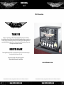
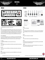
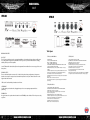
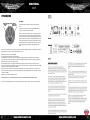
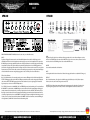
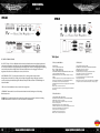
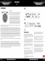
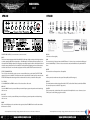
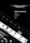
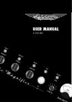
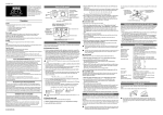
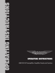
www.ashdownmusic.com
1
USER MANUAL
VALVE
CTM-15 Demo Video:
Thank you
Thank you for purchasing your Ashdown Engineering Amplifier and welcome to the family!
We really think you’ve made the right choice and know that this amplifier will give you years of great
tone and service. It is a machine though and needs to be looked after, please read through this user
manual which will help you get the most out of your new Amp and keep it running as long as some
of our happiest and very famous customers.
REGISTER ONLINE
Please register this product online so we can make sure we give you years of customer support
through our friendly in-house service centre.
Here is where you need to visit to register your product:
http://www.ashdownmusic.com/register
www.ashdownmusic.com
2
Ashdown Amplifiers reserve the right to change specifications without notice. E & O E. All contents © Ashdown 2012.
Ashdown Amplifiers reserve the right to change specifications without notice. E & O E. All contents © Ashdown 2012.
www.ashdownmusic.com
www.ashdownmusic.com
3
USER MANUAL
VALVE
CTM-300
CTM-100
VU
FACILITIES AND CONTROLS (note that these vary according to the model)
INPUTS
There are two instrument inputs marked LOW and HIGH. The LOW input is highly sensitivity and also high impedance
to suit the output from PASSIVE (Low Output) basses - The HIGH input is low sensitivity and lower impedance to suit
the output from ACTIVE (High Output) basses. Plugging an active (High Output) bass into the LOW input will overload
the input, creating a fatter, warmer and more distorted sound. Experiment by plugging your bass into either input to
achieve the desired sound. On models with a single input this will be suitable for both Passive and Active basses.
EFFECTS SEND AND RETURN
These 1/4” jack sockets should be used to connect to an external effects device or pedal board. The EFFECTS SEND
output should connect to the INPUT of the effects unit, and the output of the effects unit should be connected to the
EFFECTS RETURN input Note that the signal level is at instrument level so this loop is suitable for effects pedals.
EQ CONTROLS
Use the MIDDLE, BASS and TREBLE controls to effect the overall tone of the sound.
MID SHIFT
Causes the MIDDLE control to operate at different points in the frequency spectrum dependant on the button being
either in or out.
BASS SHIFT
Causes the Bass control to operate at different points in the frequency spectrum dependant on the button being
either in or out.
MELLOW
Softens the overall tone slightly
GAIN
This controls the level of the signal sent to the MASTER section. To achieve a cleaner sound, turn the GAIN control
down and the MASTER up. To achieve a richer, more distorted sound, turn the GAIN control up and the MASTER
down.
MASTER
This controls the overall output volume of the amplifier.
MUTE
In the in position, this switch mutes the out put of the amplifier (useful for tuning, etc.).
PRE/POST
This switch determines whether the signal from the DI OUTPUT (see Rear Panel Facilities) is taken before/PRE the
EQ section (down position) or after/POST (up position).
VU METER
The VU meter provides a visual indication of the output level of the amplifier. It also acts as a bias meter, ( not on
CTM15 ) please see the following page for more details.
BRIGHT
Adds an overall brightness to the sound when in the up position. (Note: The BRIGHT switch is not effective when the
GAIN control is set to full).
4
Ashdown Amplifiers reserve the right to change specifications without notice. E & O E. All contents © Ashdown 2012.
Ashdown Amplifiers reserve the right to change specifications without notice. E & O E. All contents © Ashdown 2012.
www.ashdownmusic.com
www.ashdownmusic.com
5
USER MANUAL
VALVE
CTM-30
CTM-15
Tech Spec:
REAR PANEL FACILITIES
DI OUTPUT
This 1/4” stereo jack socket is used to connect the amplifier to a low impedance, balanced input on a PA system
or recording mixer. The signal can be taken PRE or POST EQ (see above), ie with or without the tone shaping
added by the EQ section of the amplifier.
On the CTM30 the DI is derived directly from the output transformer and therefore is an exact copy of the sound
that you here.
SPEAKER OUTPUTS
There are dedicated Speakon connectors for 2, 4 and 8! load speaker cabinet configurations. It is important
that the correct output or outputs are used to match the impedance load of your cabinets. Please refer to the
diagrams later in this manual.
CTM 30,and 15 are fitted with jack outlets at 8 and 4 ohms.
OFF/PREHEAT
Use this switch to pre-heat the valves, bringing them up to the correct operating temperature before
performing.
STANDBY/FULL
No signal is sent to the speakers when this switch is in the STANDBY position. Switch to FULL when you are ready
to perform.
6
www.ashdownmusic.com
Ctm 300,100 AND DH200
CTM15, DH 15
Power outputs
CTM 300-- 300WATTS FROM 6 XKT88
DH200 --150 WATTS FROM 4 X 6550
CTM100-- 100WATTS FROM 2 X KT88
ALL AMPLIFIERS FEATURE USER ADJUSTABLE BIASING AND 2.4 8 OHM
OUTPUTS ON SPEAKON COMBI OUTLETS.
Pre amplifier ( all models ) 2 x ECC832 AND 2 X ECC82 + 1 X ECC99 (
CTM300)
CONTROLS Totally Passive tone shaping via Bass ,Middle Treble controls +
SHIFT controls for Bass, Middle controls, Bright and Mellow switches.
Gain and Master controls for clean and distorted tones
VU meter Dual Function for indication of output power and tube balance
and biasing
EFFECTS LOOP valve driven and recovered
DI out valve driven transformer coupled isolated ground with PRE/POST
EQ switching.
Output power 15 watts from 2 X EL84
AUTOMATIC BIAS FOR PLUG AND PLAY EASY VALVE REPLACEMENT.
4 AND 8 Ohms outputs on ¼” jack sockets
Pre amplifier ( all models ) 1 x ECC83
CONTROLS Totally Passive tone shaping via Bass ,Middle Treble
Gain and Master controls for clean and distorted tones
VU meter for indication of output power
Cool industrial wrinkle finish steel case with built in handle
Head supplied with GIG bag
DH15 combo also features a custom designed DUAL concentric “WHIZZER”
cone speaker rated at an incredible 250 watts and a cool flip top design.
CTM30, LB30 DH 30
Output power 30 watts from 4 X EL84
AUTOMATIC BIAS FOR PLUG AND PLAY EASY VALVE REPLACEMENT.
4 AND 8 Ohms outputs on ¼” jack sockets
DI out Transformer derived sampled from output to include tube
distortion ( isolated ground)
Pre amplifier ( all models ) 2 x ECC83 AND 1X ECC82
CONTROLS Totally Passive tone shaping via Bass ,Middle Treble controls +
SHIFT controls for Bass, Middle controls, Bright switch
Volume control for clean and distorted tones
VU meter for indication of output power
EFFECTS LOOP valve driven and recovered
www.ashdownmusic.com
7
USER MANUAL
VALVE
CTM-300/100
THE VU METER
WILL STILL WORK
AT REDUCED
POWER
IDEAL SETTING
KEEP OUT!
DO NOT SET ANY
TUBE THIS HIGH
The VU meter fitted to the CTM is a dual function meter detailed as
follows:
By using the push button selector switch marked “AUDIO / BIAS” the
functions are accessed in the following manner:
1/ “AUDIO” - In audio mode the meter is set to read the audio output of
each of the six power tubes and each can be measured by utilising the
rotary selector switch on the front panel. Whilst playing this is the normal
mode of operation of the meter and the reading obtained will be a direct
indication of the power being produced by each output tube, the meter
is calibrated so that when the needle reaches the start of the red section
the power tube being measured will be producing maximum clean
volume.
The switch can be rotated to select any of the power tubes and its relative output will be indicated on the meter, note that when
performing this test you will need to play at equal volume for each test.
2/ “BIAS” - In this mode the meter will glow RED.
To check the bias of the output tubes proceed as follows:
Run the amplifier for at least 10 mins to allow the output tubes to fully heat up with the amplifier set to mute. Standby on.
Select.. Tube 1 and with an insulated jewelers screwdriver gently adjust the trimmer situated on the rear panel. The reading to
aim for is the needle just at the start of the red ie 0db.
Note that although each tube can be adjusted individually it is possible to get tubes that cannot be adjusted to the correct
reading, these can still be used providing the reading is not in the red, a lower reading is acceptable and will note impact audibly
on the power output or sound quality of the amplifier.
Please also note that the trimmers are 25 turn types to make adjustment easy, This type of adjuster has no end stop so if you
reach a point where the adjuster will not give any more adjustment then the output tube will have to be replaced if the reading
is to high ie in the RED.
Repeat this for each of the six output tubes in turn.
RETURN THE METER TO “audio” MODE AFTER BIASING. DO NOT RUN THE AMPLIFIER IN BIAS MODE WHILST PLAYING.
Note there is a protection fuse fitted to each of the output tubes and if no reading is obtained on the meter this fuse will have
8
www.ashdownmusic.com
www.ashdownmusic.com
9
USER MANUAL
VALVE
NOTES:
10
www.ashdownmusic.com
www.ashdownmusic.com
11
USER MANUAL
VALVE
CTM-300
CTM-100
VU
EINRICHTUNGEN UND EINSTELLUNGEN (beachten Sie, dass diese je nach Modell variieren)
INPUTS
Es gibt zwei Eingänge für Instrumente die mit LOW-und HIGH gekennzeichnet sind. Der LOW-Eingang ist sehr
empfindlich und hat auch eine hohe Impedanz um den Ausgang von passiven (Low Output) Bässen zu entsprechen.
Der HIGH-Eingang ist weniger empfindlich und hat eine niedrigere Impedanz um an den Ausgang von aktiven (High
Output) Bässe zu entsprechen. Das Anschließen eines aktiven (High Output) Bass in den LOW-Eingang wird zum
überlasten des Eingangssignals führen und die Schaffung eines dickeren, wärmeren und verzerrten Tons ermöglichen.
Experimentieren Sie, indem Sie Ihren Bass an einem der beiden Eingänge einstöpseln, um den gewünschten Klang zu
erzielen. Bei Modellen mit einem einzigen Eingang eignet sich die sowohl für passive als auch aktive Bässe.
Effects Send und Return
Diese ¼ Inch Klinkenbuchse sollte verwendet werden, um ein externes Effektgerät oder Pedal Bord anschließen. Der
EFFECTS SEND Ausgang sollte mit dem INPUT des Effektgeräts verbunden werden und der Ausgang des Effektgeräts
sollte mit dem EFFECTS RETURN-Eingang verbunden werden. Beachten Sie, dass der Signalpegel dem Instrument
Pegel entspricht, so dass diese Schleife für Effektpedale ist.
EQ CONTROLS - Verwenden Sie die MIDDLE-, BASS- und TREBLE-Regler um den Gesamtklang des Tons zu beeinflussen.
Die MID SHIFT-Taste bewirkt, dass die MIDDLE-Regler an verschiedenen Stellen im Frequenzspektrum abhängig von
einander arbeiten. Dies kommt darauf an, ob der Knopf eingedrückt ist oder nicht. Der BASS SHIFT bewirkt, dass die
Bass-Regler an verschiedenen Stellen im Frequenzspektrum abhängig voneinander arbeiten. Dies kommt darauf an,
ob der Knopf eingedrückt ist oder nicht. Der BRIGHT-Schalter fügt eine allgemeine Helligkeit auf den Klang, wenn der
Schalter sich in der oberen Position befindet. (Hinweis: Der BRIGHT-Schalter ist nicht wirksam, wenn der GAIN-Regler
voll aufgedreht ist). Der MELLOW Schalter mildert den Gesamtklang leicht.
12
GAIN
Regelt den Pegel des Signals das an die Master-Sektion gesendet wird. Um einen klareren Klang zu erreichen,
drehen Sie den GAIN-Regler nach unten und den MASTER nach oben. Um einen reicheren, verzerrten Sound zu
erreichen, drehen Sie den GAIN-Regler nach oben und den MASTER unten.
MASTER
Steuert die Gesamtlautstärke des Verstärkers.
MUTE
In der eingedrückten Position schaltet dieser Schalter der Ausgang des Verstärkers aus (nützlich für Tuning, etc.).
PRE/POST
Dieser Schalter bestimmt, ob das Signal aus dem DI-Ausgang (siehe Rückseite) vor die EQ-Sektion (untere
Position) oder nach (obere Position) ihr gesendet werden soll.
VU METER - Das VU-Meter bietet eine visuelle Anzeige der Ausgangspegel des Verstärkers. Es wirkt auch als
Vorspannungsmessgerät (nicht auf CTM15). Sehen Sie auf der folgenden Seite für weitere Details nach.
Ashdown Amplifiers reserve the right to change specifications without notice. E & O E. All contents © Ashdown 2012.
Ashdown Amplifiers reserve the right to change specifications without notice. E & O E. All contents © Ashdown 2012.
www.ashdownmusic.com
www.ashdownmusic.com
13
USER MANUAL
VALVE
CTM-30
CTM-15
Tech Spec:
RÜCKSEITE MIT EINRICHTUNGEN
D.I. OUTPUT - Diese 1/4 “-Stereo-Klinkenbuchse dient dazu, den Verstärker mit einem niedrigen Impedanz und
symmetrischen Eingang an einem PA-System oder einem Aufnahme Mischpult anzuschließen. Das Signal kann
vor oder nach den EQ (siehe oben) geleitet werden. Zum Beispiel: mit oder ohne Ton hinzugefügter Formgebung
durch die EQ des Verstärkers erfolgt. Auf der CTM30 wird die D.I. direkt von dem Ausgangs-Transformator
abgeleitet und ist daher eine exakte Kopie der Sounds, den Sie hören.
LAUTSPRECHER OUTPUTS - Es sind Speakon Anschlüsse für 2, 4 und 8 geladene LautsprecherboxKonfigurationen vorhanden! Es ist wichtig, dass der richtige Ausgang/die richtigen Ausgänge verwendet
werden, um die Impedanz der Belastung Ihrer Kabinette anzupassen. Bitte beachten Sie die Abbildungen in
diesem Handbuch.
CTM 30 und 15 sind mit Buchsen Outlets in 8 und 4 Ohm ausgestattet.
OFF/PREHEAT - Verwenden Sie diesen Schalter zum Vorheizen der Ventile. Die bringt sie auf die richtige
Betriebstemperatur.
STANDBY/FULL - Es wird kein Signal an die Lautsprecher gesendet, wenn sich dieser Schalter in der Stellung
STANDBY befindet. Wechseln Sie zu FULL, wenn Sie bereit sind es durchzuführen.
14
www.ashdownmusic.com
Ctm 300,100 AND DH200
CTM15, DH 15
Power outputs
CTM 300-- 300WATTS FROM 6 XKT88
DH200 --150 WATTS FROM 4 X 6550
CTM100-- 100WATTS FROM 2 X KT88
ALL AMPLIFIERS FEATURE USER ADJUSTABLE BIASING AND 2.4 8 OHM
OUTPUTS ON SPEAKON COMBI OUTLETS.
Pre amplifier ( all models ) 2 x ECC832 AND 2 X ECC82 + 1 X ECC99 (
CTM300)
CONTROLS Totally Passive tone shaping via Bass ,Middle Treble controls +
SHIFT controls for Bass, Middle controls, Bright and Mellow switches.
Gain and Master controls for clean and distorted tones
VU meter Dual Function for indication of output power and tube balance
and biasing
EFFECTS LOOP valve driven and recovered
DI out valve driven transformer coupled isolated ground with PRE/POST
EQ switching.
Output power 15 watts from 2 X EL84
AUTOMATIC BIAS FOR PLUG AND PLAY EASY VALVE REPLACEMENT.
4 AND 8 Ohms outputs on ¼” jack sockets
Pre amplifier ( all models ) 1 x ECC83
CONTROLS Totally Passive tone shaping via Bass ,Middle Treble
Gain and Master controls for clean and distorted tones
VU meter for indication of output power
Cool industrial wrinkle finish steel case with built in handle
Head supplied with GIG bag
DH15 combo also features a custom designed DUAL concentric “WHIZZER”
cone speaker rated at an incredible 250 watts and a cool flip top design.
CTM30, LB30 DH 30
Output power 30 watts from 4 X EL84
AUTOMATIC BIAS FOR PLUG AND PLAY EASY VALVE REPLACEMENT.
4 AND 8 Ohms outputs on ¼” jack sockets
DI out Transformer derived sampled from output to include tube
distortion ( isolated ground)
Pre amplifier ( all models ) 2 x ECC83 AND 1X ECC82
CONTROLS Totally Passive tone shaping via Bass ,Middle Treble controls +
SHIFT controls for Bass, Middle controls, Bright switch
Volume control for clean and distorted tones
VU meter for indication of output power
EFFECTS LOOP valve driven and recovered
www.ashdownmusic.com
15
USER MANUAL
VALVE
CTM-300/100
THE VU METER
WILL STILL WORK
AT REDUCED
POWER
IDEAL SETTING
KEEP OUT!
DO NOT SET ANY
TUBE THIS HIGH
VU METER - Das VU-Meter bietet eine visuelle Anzeige der Ausgangspegel
des Verstärkers. Es wirkt auch als Vorspannungsmessgerät (nicht auf
CTM15). Sehen Sie auf der folgenden Seite für weitere Details nach.
1/”AUDIO” - Im Audio-Modus wird der Zähler auf den Audio-Ausgang
von jedem der sechs Endstufenröhren gelesen und jeder kann durch
die Nutzung der Drehschalter auf der Frontplatte gemessen werden.
Während der Wiedergabe wird die normale Betriebsart des Zählers
erhalten und das Lesen ist ein direktes Indiz für die Leistung die von
jedem Ausgangs Rohr hergestellt wird. Ist das Gerät so kalibriert, dass,
wenn die Nadel Beginn des roten Abschnitts erreicht, die Endstufenröhre
ein höchstmögliches sauberes Volumen erzeugt. Der Schalter kann
gedreht werden, um eine der beliebigen Endstufenröhren auszusuchen.
Seine relative Ausgabe wird auf dem Messgerät angezeigt werden. Beachten Sie, dass Sie bei der Durchführung dieses Tests für
jeden Test in gleicher Lautstärke spielen müssen.
2/”BIAS” - In diesem Modus leuchtet das Messgerät rot. Um die Vorspannung der Endröhren zu überprüfen müssen Sie wie
folgt vorgehen: Starten Sie den Verstärker für mindestens 10 Minuten, damit die Endröhren vorheizen, mit dem Verstärker auf
stumm geschaltet. Standby an. Wählen Sie Röhre 1 und justieren Sie mit einem isolierten Juwelierschraubenzieher vorsichtig den
Trimmer der sich auf der Rückseite befindet. Der Zielmesswert für die Nadel ist der Punkt, wo sie gerade am Beginn der roten
Anzeige ankommt, das heißt bei 0db. Beachten Sie, dass, obwohl jeder Röhre individuell eingestellt werden kann, es möglich
ist, dass die Röhre nicht auf korrekte Ablesung eingestellt werden kann. Diese können noch verwendet werden, vorausgesetzt
der Messwert ist nicht im roten Bereich. Ein geringer Messwert ist akzeptabel und Sie werden Auswirkungen hören; beachten
Sie die Leistung oder Klangqualität des Verstärkers. Bitte beachten Sie auch, dass die Trimmer 25 wiederum Typen sind, um
Anpassungen einfach zu gestalten. Diese Art der Einstellung hat keinen Endanschlag. Wenn Sie also einen Punkt erreichen, wo
der Regler nicht mehr Anpassung ermöglicht, dann muss die Endröhre, wenn der Messwert ist zu hoch, das heißt in die Anzeige
rot ist, ersetzt werden. Wiederholen dieses für jede der sechs Ausgangs Rohre in der Reihe.
Stellen Sie das Messgerät auf den “Audio”-Modus nach der Vorspannung. Benutzen Sie den Verstärker in BIAS MODE während des
Spielens.
Anmerkung: Es gibt eine Schutzsicherung, angepasst auf jede der Endröhren und wenn keine Ablesung auf dem Zähler
erscheint, wird diese Sicherung wohl versagt haben. Die Sicherungen befinden sich neben dem Ausgangs befindet. sie
schützen die korrekte Bewertung, die 315mA flink ist. im Falle einer durchgebrannten Sicherung müssen sie mit Sicherungen
mit dem korrekten Wert und Typ ersetzt werden. Die Sicherungen befinden sich neben dem Ausgang. Sie schützen die korrekte
Bewertung, die 315mA quick blow ist. Im Falle einer durchgebrannten Sicherung müssen sie mit Sicherungen mit dem korrekten
Wert und Typ ersetzen. Ein ständiges Blasen der Sicherung würde bedeuten, dass entweder eine falsch voreingenommenene
Ausgangs Röhre oder eine defekte Endröhre das Problem sind.failed.
16
www.ashdownmusic.com
www.ashdownmusic.com
17
USER MANUAL
VALVE
NOTES:
18
www.ashdownmusic.com
www.ashdownmusic.com
19
USER MANUAL
VALVE
CTM-300
CTM-100
VU
FACILITIES AND CONTROLS (note that these vary according to the model)
INPUTS
There are two instrument inputs marked LOW and HIGH. The LOW input is highly sensitivity and also high impedance
to suit the output from PASSIVE (Low Output) basses - The HIGH input is low sensitivity and lower impedance to suit
the output from ACTIVE (High Output) basses. Plugging an active (High Output) bass into the LOW input will overload
the input, creating a fatter, warmer and more distorted sound. Experiment by plugging your bass into either input to
achieve the desired sound. On models with a single input this will be suitable for both Passive and Active basses.
EFFECTS SEND AND RETURN
These 1/4” jack sockets should be used to connect to an external effects device or pedal board. The EFFECTS SEND
output should connect to the INPUT of the effects unit, and the output of the effects unit should be connected to the
EFFECTS RETURN input Note that the signal level is at instrument level so this loop is suitable for effects pedals.
EQ CONTROLS
Use the MIDDLE, BASS and TREBLE controls to effect the overall tone of the sound.
MID SHIFT
Causes the MIDDLE control to operate at different points in the frequency spectrum dependant on the button being
either in or out.
BASS SHIFT
Causes the Bass control to operate at different points in the frequency spectrum dependant on the button being
either in or out.
MELLOW
Softens the overall tone slightly
GAIN
This controls the level of the signal sent to the MASTER section. To achieve a cleaner sound, turn the GAIN control
down and the MASTER up. To achieve a richer, more distorted sound, turn the GAIN control up and the MASTER
down.
MASTER
This controls the overall output volume of the amplifier.
MUTE
In the in position, this switch mutes the out put of the amplifier (useful for tuning, etc.).
PRE/POST
This switch determines whether the signal from the DI OUTPUT (see Rear Panel Facilities) is taken before/PRE the
EQ section (down position) or after/POST (up position).
VU METER
The VU meter provides a visual indication of the output level of the amplifier. It also acts as a bias meter, ( not on
CTM15 ) please see the following page for more details.
BRIGHT
Adds an overall brightness to the sound when in the up position. (Note: The BRIGHT switch is not effective when the
GAIN control is set to full).
20
Ashdown Amplifiers reserve the right to change specifications without notice. E & O E. All contents © Ashdown 2012.
Ashdown Amplifiers reserve the right to change specifications without notice. E & O E. All contents © Ashdown 2012.
www.ashdownmusic.com
www.ashdownmusic.com
21
USER MANUAL
VALVE
CTM-30
CTM-15
Tech Spec:
REAR PANEL FACILITIES
DI OUTPUT
This 1/4” stereo jack socket is used to connect the amplifier to a low impedance, balanced input on a PA system
or recording mixer. The signal can be taken PRE or POST EQ (see above), ie with or without the tone shaping
added by the EQ section of the amplifier.
On the CTM30 the DI is derived directly from the output transformer and therefore is an exact copy of the sound
that you here.
SPEAKER OUTPUTS
There are dedicated Speakon connectors for 2, 4 and 8! load speaker cabinet configurations. It is important
that the correct output or outputs are used to match the impedance load of your cabinets. Please refer to the
diagrams later in this manual.
CTM 30,and 15 are fitted with jack outlets at 8 and 4 ohms.
OFF/PREHEAT
Use this switch to pre-heat the valves, bringing them up to the correct operating temperature before
performing.
STANDBY/FULL
No signal is sent to the speakers when this switch is in the STANDBY position. Switch to FULL when you are ready
to perform.
Ctm 300,100 AND DH200
Power outputs
CTM 300-- 300WATTS FROM 6 XKT88
DH200 --150 WATTS FROM 4 X 6550
CTM100-- 100WATTS FROM 2 X KT88
ALL AMPLIFIERS FEATURE USER ADJUSTABLE BIASING AND 2.4 8 OHM
OUTPUTS ON SPEAKON COMBI OUTLETS.
Pre amplifier ( all models ) 2 x ECC832 AND 2 X ECC82 + 1 X ECC99 (
CTM300)
CONTROLS Totally Passive tone shaping via Bass ,Middle Treble controls +
SHIFT controls for Bass, Middle controls, Bright and Mellow switches.
Gain and Master controls for clean and distorted tones
VU meter Dual Function for indication of output power and tube balance
and biasing
EFFECTS LOOP valve driven and recovered
DI out valve driven transformer coupled isolated ground with PRE/POST
EQ switching.
Output power 15 watts from 2 X EL84
AUTOMATIC BIAS FOR PLUG AND PLAY EASY VALVE REPLACEMENT.
4 AND 8 Ohms outputs on ¼” jack sockets
Pre amplifier ( all models ) 1 x ECC83
CONTROLS Totally Passive tone shaping via Bass ,Middle Treble
Gain and Master controls for clean and distorted tones
VU meter for indication of output power
Cool industrial wrinkle finish steel case with built in handle
Head supplied with GIG bag
DH15 combo also features a custom designed DUAL concentric “WHIZZER”
cone speaker rated at an incredible 250 watts and a cool flip top design.
CTM30, LB30 DH 30
Output power 30 watts from 4 X EL84
AUTOMATIC BIAS FOR PLUG AND PLAY EASY VALVE REPLACEMENT.
4 AND 8 Ohms outputs on ¼” jack sockets
DI out Transformer derived sampled from output to include tube
distortion ( isolated ground)
Pre amplifier ( all models ) 2 x ECC83 AND 1X ECC82
CONTROLS Totally Passive tone shaping via Bass ,Middle Treble controls +
SHIFT controls for Bass, Middle controls, Bright switch
Volume control for clean and distorted tones
VU meter for indication of output power
EFFECTS LOOP valve driven and recovered
CTM15, DH 15
22
www.ashdownmusic.com
www.ashdownmusic.com
23
USER MANUAL
VALVE
CTM-300/100
THE VU METER
WILL STILL WORK
AT REDUCED
POWER
IDEAL SETTING
KEEP OUT!
DO NOT SET ANY
TUBE THIS HIGH
The VU meter fitted to the CTM is a dual function meter detailed as
follows:
By using the push button selector switch marked “AUDIO / BIAS” the
functions are accessed in the following manner:
1/ “AUDIO” - In audio mode the meter is set to read the audio output of
each of the six power tubes and each can be measured by utilising the
rotary selector switch on the front panel. Whilst playing this is the normal
mode of operation of the meter and the reading obtained will be a direct
indication of the power being produced by each output tube, the meter
is calibrated so that when the needle reaches the start of the red section
the power tube being measured will be producing maximum clean
volume.
The switch can be rotated to select any of the power tubes and its relative output will be indicated on the meter, note that when
performing this test you will need to play at equal volume for each test.
2/ “BIAS” - In this mode the meter will glow RED.
To check the bias of the output tubes proceed as follows:
Run the amplifier for at least 10 mins to allow the output tubes to fully heat up with the amplifier set to mute. Standby on.
Select.. Tube 1 and with an insulated jewelers screwdriver gently adjust the trimmer situated on the rear panel. The reading to
aim for is the needle just at the start of the red ie 0db.
Note that although each tube can be adjusted individually it is possible to get tubes that cannot be adjusted to the correct
reading, these can still be used providing the reading is not in the red, a lower reading is acceptable and will note impact audibly
on the power output or sound quality of the amplifier.
Please also note that the trimmers are 25 turn types to make adjustment easy, This type of adjuster has no end stop so if you
reach a point where the adjuster will not give any more adjustment then the output tube will have to be replaced if the reading
is to high ie in the RED.
Repeat this for each of the six output tubes in turn.
RETURN THE METER TO “audio” MODE AFTER BIASING. DO NOT RUN THE AMPLIFIER IN BIAS MODE WHILST PLAYING.
Note there is a protection fuse fitted to each of the output tubes and if no reading is obtained on the meter this fuse will have
Face avant
Face arrièrE
Face avant
Inputs
Vous disposez d’une entrée et d’un interrupteur vous permettant de
choisir le type d’impédance de l’instrument utilisé. Passive et Active.
Le mode Passif (interrupteur relâché) offre une haute sensibilité et
une haute impédance pour s’adapter aux basses passives. Le mode
actif (interrupteur enfoncé) offre une sensibilité et une impédance
nettement plus basse afin de correspondre au signal provenant
d’une basse active.
INPUT CONTROL
Le réglage input control permet de définir le niveau du signal
d’entrée dans le préampli en coordination avec le vu- mètre; Il
doit être réglé de façon à ce que la valeur moyenne soit 0vu et
en obtenant des pics occasionnels en zone rouge. Notez que ces
paramètres pourront être réajustes après avoir modifié les valeurs
d’égalistation.
PUSH FLAT/SHAPE
En position relâché, ce bouton enclenche un circuit de préégalisation fixe qui donne au son une certaine clarté et un caractère
punchy. Appuyer sur ce bouton pour obtenir une égalisation plate.
Cette fonction peut également être contrôlée par une pédale, pour
que la pédale soit opérationnelle le bouton doit être en position off.
VALVE DRIVE
Cette fonction permet d’acheminer le signal soit vers une section
d’amplificateur à transistors (son clair), soit vers une section
d’amplification à lampes double triode afin d’y ajouter du
caractère; de la chaleur avec un réglages à 9h ; un léger grain
sur 12h ; et jusqu’à la saturation des lampes lorsque le réglage est
amené au maximum.
Un mélange des deux sections d’amplification peut être réalisé avec
ce réglage.
N.B : la quantité de saturation est également dépendante du
réglage du gain d’entrée.
24
www.ashdownmusic.com
VALVE DRIVE/IN OUT
Ce bouton active/désactive la fonction Valve Drive. Cette fonction
peut également être accessible à partir du pédalier FS4 en option
(pour que le pédalier fonctionne, cette fonction doit être désactivée).
EQ IN/OUT
Ce bouton active ou désactive la section Egalisation. Cette fonction
peut également être accessible à partir du pédalier FS4 en option
(pour que le pédalier fonctionne, cette fonction doit être désactivée).
EQUALISER
La section d’égalisation comprend les réglages « BASS/
MIDDLE/ TREBLE» (Graves/ Mediums/ Aigus) et les deux jeux de
potentiomètres linéaires placés entre ceux-ci.
Vous pouvez utiliser cet égaliseur de deux manières différentes :
1- Comme un simple réglage des tonalités graves, médiums
et aigües, que l’on trouve traditionnellement sur nombre
d’amplificateurs classiques. Vous laisserez alors les deux jeux de
potentiomètres linéaires placés entre ceux-ci en position centrale et
n’utiliserez que les boutons « BASS/ MIDDLE/ TREBLE» (Graves/
Mediums/ Aigus) pour régler la tonalité générale.
2 - Comme un égaliseur polyvalent, simple à comprendre et à
régler. En plus des réglages « BASS/ MIDDLE/ TREBLE», vous
utiliserez les deux jeux de potentiomètres linéaires placés entre
ceux-ci qui vous permettront de façonner le son à votre guise, en
travaillant sur le Bas et le Haut medium. Cette section se caractérise
donc par la simplicité d’un réglage de tonalité à trois boutons avec
la flexibilité d’un égaliseur graphique.
COMPRESSION
L’ajout d’une faible quantité de compression vous permet de donner
un son beaucoup plus profond et de jouer à un volume plus élevé
sans attaquer les cordes plus fort ce qui permet d’éviter les pics de
distorsion de l’étage de sortie de l’amplificateur.
Vous trouverez également que le son sera plus défini en mettant
en valeur la dynamique de votre jeu et en offrant également une
meilleur définition.
www.ashdownmusic.com
25
USER MANUAL
VALVE
Une valeur de compression élevée peut être utilisée comme un effet mais elle aura tendance à réduire la dynamique de votre jeu de manière
à ce que le volume des notes reste le même, que les cordes soient jouées plus ou moins durement.
La compression permet également d’ajouter du sustain aux notes jouées en maintenant leur volume les rendant ainsi plus longues.
Le potentiomètre ajuste le niveau de compression appliquée.
Pour que cela fonctionne correctement le niveau d’entre doit être correctement réglé comme décrit précédemment. Lorsque le niveau
d’entrée est correctement règle il n’y aura quasiment aucune différence de volume que la compression soit activée ou non. L’ampli compense
automatiquement la réduction du niveau en augmentant le gain global pour le restaurer à son niveau de pré compression. A cause de ceci
vous remarquerez peut être une augmentation du bruit de fond avec des valeurs élevées.
NOTES:
COMPRESSION IN / OUT - Ce bouton-poussoir permet d’activer/désactiver la compression. Cette fonction peut également être commandée à
partir du pédalier Ashdown FS-4. Pour que le pédalier fonctionne ce bouton doit être sur la position OUT.
SUB HARMONICS
Cette section est constituée d’un interrupteur IN / OUT et d’un contrôle de niveau. Lorsque l’interrupteur est en position IN, des Sub
Harmoniques à l’octave inférieure aux notes jouées sont produites. Le niveau de ces Sub Harmoniques par rapport au son de basse direct
peut être ajusté en utilisant le contrôle de niveau. Ceci est très efficace pour épaissir le son et vous constaterez à l’usage qu’il suffit d’un
dosage minime de cette octave inférieure pour vraiment remplir le son en lui donnant un caractère qu’il n’est pas possible d’obtenir par
d’autres moyens. Le niveau de Sub Harmonics est aussi dépendant de la valeur du potentiomètre BASS. Cette fonction s’active/désactive à
l’aide du bouton situé à gauche du potentiomètre de contrôle Sub Harmonics.
DIRECT INJECT
Une sortie D.I. symétrique est disponible sur la face avant avec une prise XLR en métal à verrouillage. Un bouton poussoir situé sur la face
avant vous permet de choisir si le signal sortant de cette prise XLR est Pré E.Q (bouton enclenché) ou s’il est post EQ, Post Sub et Post Effets
(bouton relaché).
Il est et calibré pour permettre de se connecter à l’entrée microphone d’une table de mixage, pour l’injection directe dans un système
de sonorisation ou pour enregistrer. Elle doit SEULEMENT être utilisée pour se connecter à une entrée microphone symétrique. Elle n’est
pas prévue pour tout autre type de connexion. Elle dispose d’une terre flottante calibrée pour la console de mixage à laquelle elle va être
connectée et ne nécessite pas de mise à la terre. Elle n’est pas non plus affectée par l’alimentation fantôme d’une entrée microphone.
Assurez-vous que votre fiche XLR n’a pas une connexion interne à la terre car cela relierait le système à la terre du châssis de l’amplificateur
et pourrait causer des problèmes de ronflements.
PUSH TO MUTE
En pressant sur ce bouton on mute (Mode muet) : la sortie du pré-ampli à l’ampli de puissance, la sortie DI et la sortie ligne tout en laissant
en fonction la sortie accordeur.
Une Led placée à cote du bouton poussoir s’allume lorsque l’amplificateur est mis en mode mute.
Cette fonction ne peut se faire qu’à partir du bouton poussoir mute situe sur le panneau avant. En pressant ce bouton poussoir tous les sons
de l’amplificateur sont coupes ce qui permet le réglage silencieux de votre basse via la prise accordeur. Relâchez ce bouton et vous voila à
nouveau en action.
TUNER OUT
Cette sortie présente un signal de niveau ligne qui peut être utilisée autant pour une connexion permanente à un accordeur que comme une
sortie ligne pour asservir d’autres amplificateurs de puissance. Elle fonctionne même si l’ampli est mis en mode mute.
LIGNE OUT
Ce connecteur de sortie délivre un signal de niveau ligne pour le raccordement à un amplificateur de puissance externe pilotant des hauts
parleurs additionnels.
NIVEAU DE SORTIE - La commande du niveau de sortie vous permet d’ajuster le niveau global de votre amplificateur. Ne le faites pas
fonctionner pendant de longues périodes de temps à un volume élevé sans protections auditives, ou à un niveau sonore qui provoque des
malaises.
PANNEAU ARRIÈRE
ENTREE LIGNE - Le panneau arrière dispose d’une entrée ligne permettant la connexion d’autres sources de signal dans le système. Ceci peut
être utilisé pour brancher un CD ou Lecteur MP3 dans l’amplificateur pour pratiquer, répéter ou pour connecter un deuxième préampli.
EFFECTS/SEND AND RETURN
Une boucle d’insertion d’effets est disponible et elle offre un niveau de 0dB . Au besoin, la sortie EFFECTS SEND peut aussi être utilisée
comme une sortie ligne. Le chemin du signal à travers le préampli est rompu seulement lorsqu’un jack est inséré dans la prise EFFECTS
RETURN. La prise EFFECTS SEND prélève le signal après l’E.Q, le préampli, la compression et le Processeur Sub Harmonics.
Connecteur 4-WAY FOOTSWITCH - Connecteur jack 6,35 mm pour pédalier Ashdown FS-4 uniquement. Pour que le pédalier fonctionne il
est impératif que tous les boutons correspondants aux fonctions contrôlées soient en position OUT.
Toujours raccorder le pédalier avant la mise sous tension de l’amplificateur car la pédale est alimentée par l’amplificateur et elle envoie une
série de données à l’amplificateur afin d’exploiter ces différentes fonctions.
Chacune des 4 fonctions disponibles pour la sélection est indiquée par une LED qui sera s’allume lorsque cette fonction est sélectionné à
partir de la pédale.
26
www.ashdownmusic.com
www.ashdownmusic.com
27
www.ashdownmusic.com
Ashdown Design & Marketing Ltd
Stevens Farm (The Stables), Mashbury Road, Chignal St James, Chelmsford, Essex CM1 4TX