1
FT5733/5433
(contains FT4727/4427 Information)
FIELD SERVICE
MANUAL
SECTION 1
SPECIFICATIONS
1. SPECIFICATIONS
Configuration:
Desktop
Copy Process:
Dry electrostatic transfer system
Originals:
Sheet/Book
Original Size:
Maximum
Copy Paper Size:
Maximum 11" x 17"
Minimum 51/2" x 81/2"
(Duplex Copying)
Multiple:
Single/Overlay:
11" x 17"
(lengthwise)
81/2" x 11" (sideways)
Maximum 11" x 17"
Minimum 81/2" x 11"
Copy Paper Weight:
• 250-sheet paper tray and 1000-sheet large
capacity tray:
14 _34lb
• By-pass feed table:
14 _43lb
• Duplex and overlay:
17 _28lb
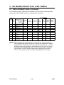
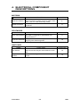
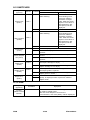
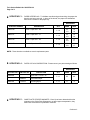
Reproduction Ratios:
4 Enlargement and 6 Reduction
FT5733/5433
Enlargement
200%
155%
129%
121%
Full Size
100%
Reduction
93%
85%
77%
74%
65%
50%
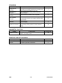
Receiving Tray
Capacity:
250 sheets (81/2" x 14" and smaller)
100 sheets (11" x 17")
Power Source:
115V, 60HZ, more than 12A
FT5733/5433
1-1
FSM
Rev. 10/92
Power Consumption:
Maximum: 1.5 KW
Warm-up: 0.77 KW
Stand-by: 0.14 KW
Copy Cycle (average): 1.2 KW
Noise Emission:
Stand-by: less than 40 dB
Copy Cycle (average):
less than 57 dB (copier only)
less than 59 dB (full system)
Maximum:
less than 62 dB (copier only)
less than 63 dB (full system)
Dimensions:
Width
Depth
Height
FT5733
34.3" (42.2")
23.6"
21.3" (22.6")
FT5433
34.3" (42.2")
23.6"
21.3" (22.6")
( ): When the by-pass feed table is opened, the copy tray is
extended, and the platen cover is installed.
Weight:
Copier only (Without the optional platen
cover=Approximately 2 kg)
FT5733: approximately 194.0 lb
FT5433: approximately 185.2 lb
Zoom:
From 50% to 200% in 1% steps
Copying Speed:
33 copies/minute (81/2" x 11" sideways)
18 copies/minute (11" x 17")
Warm-up Time:
Less than 2 minutes (20°C, 68°F)
FSM
1-2
FT5733/5433
Rev. 1/94
First Copy Time:
Black copy:
4.9 seconds (81/2" x 11" sideways)
FT5733/5433: (Large capacity tray feed)
Color copy:
7.0 seconds
FT5733/5433: (Large capacity tray feed)
Copy Number Input:
Ten keys, 1 to 999 (count up or count down)
Manual Image Density: 7 steps
Automatic Reset:
1 minute standard setting; can also be set to
3 minutes or no auto reset.
Copy Paper Capacity: • By-pass feed table; approx. 20 sheets
• Paper tray: approx. 250 sheets
• Large capacity tray; approx. 1000 sheets
Toner Replenishment: Black: cartridge exchange
(320 g/cartridge) yield 10,500 copies
Color: cartridge exchange
(60 g/cartridge) yield 1300 copies
Black: (1000 g/bag) yield 80,000 copies
Developer
Replenishment:
Color: (400 g/bag) yield 15,000 copies
Optional Equipment:
• Platen cover
•
•
•
•
•
•
•
•
•
•
•
•
FT5733/5433
DF56, Document feeder
PS250, Paper tray unit with three paper tray
CS2090, 20 bin mini sorter
ST22, 20 bin sorter stapler
TYPE G Sorter adapter (needed when
installing the mini, or the sorter stapler)
TYPE G Interface PCB (needed when
installing the sorter stapler or the menu
reader)
MR20, Menu reader
RE12, Editor (only for FT5733)
TYPE B, Editing interface adapter (needed
when installing the editor)
CU150, Color development unit
Key counter
DLT counter (service part)
1-3
FSM
SECTION 2
COMPONENT LAYOUT
AND DESCRIPTIONS
Rev. 11/92
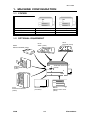
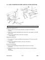
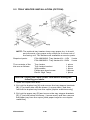
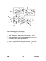
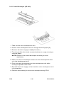
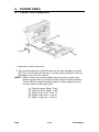
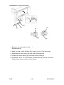
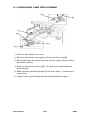
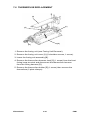
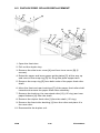
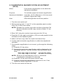
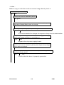
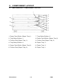
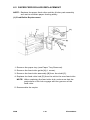
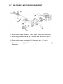
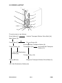
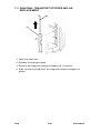
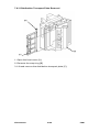
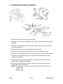
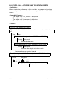
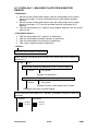
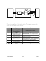
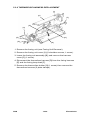
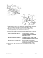
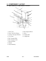
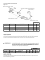
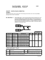
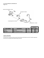
1. MACHINE CONFIGURATION
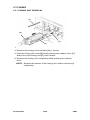
1.1 COPIER
UPPER TRAY
LOWER TRAY
LCT
FT5733(A074)
DUPLEX
250
1,000
FT5433(A073)
250
250
1,000
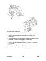
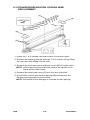
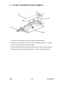
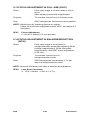
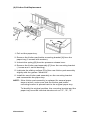
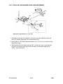
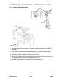
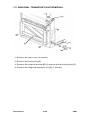
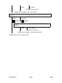
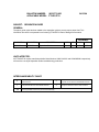
1.2 OPTIONAL EQUIPMENT
MR20
MENU READER (A952)
DF56
ARDF (A497)
SORTER ADAPTER
(A328)
CS2090
20 BIN SORTER
(A423)
ST22
SORTER STAPLER
(A366)
FSM
RE12
EDITOR (A916)
SYSTEM TABLE
(438-MIU)
2-1
PS250
PAPER TRAY UNIT
(A326)
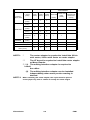
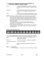
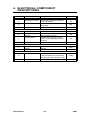
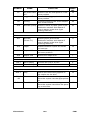
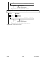
FT5733/5433
REQUIRED OPTIONAL
EQUIPMENT
COPIER
1 TRAY
(A325)
PAPER
TRAY UNIT
SORTER
EDITING
INTERFACE
TYPE 1 TYPE 2 TYPE3 ADAPTER
INTERFACE
PCB
(A069) (A074) (A073)
ADAPTER
(A344)
(A328)
(A345)
3 TRAY
(A326)
o
o
o
10 BIN
(A327)
o
o
o
20 BIN MINI
(A423)
o
o
o
*
20 BIN MIDI
(A411)
o
o
o
*
20 BIN
STAPLER
(A366)
o
o
o
*
ARDF
(A497)
o
o
o
EDITOR (A916)
x
o
x
MENU READER (A952)
o
o
o
COLOR DEVELOPMENT
UNIT (A337)
o
o
o
SORTER
DOCUMENT
FEEDER
**
* **
**
NOTE1: *
The sorter adapter is required to install the 20 bin
mini sorter, 20 bin midi sorter or sorter stapler.
**
The I/F board is required to install the sorter stapler
or Menu Reader.
** *(1) The editing interface adapter is required to
install
the editor.
(2) The editing interface adapter can be installed
independently when more precise erasing is
desired.
NOTE 2: When installing the sorter stapler, the copier must be placed
on the paper tray unit or a table of exactly the same height.
FT5733/5433
2-2
FSM
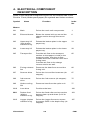
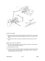
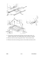
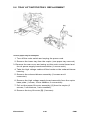
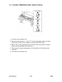
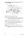
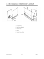
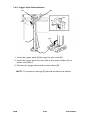
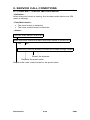
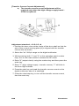
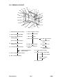
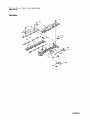
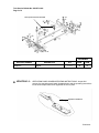
2. MECHANICAL COMPONENT LAYOUT
5
6
7 8 9 10
11
12
4
13
3
14
2
15
16
17
18
19
20
1
42
41
40
21
39
38
37
36
35
34
33
22
32
31
30
29
28
27
26
25
24
23
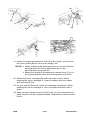
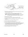
1. 3rd Mirror
2. 2nd Mirror
3. 1st Mirror
4. Exposure Lamp
5. Lens
6. Cleaning Brush
7. Quenching Lamp
8. Cleaning Blade
9. Change Corona Unit
10. OPC Drum
11. 6th Mirror
12. Erase Unit
13. 4th Mirror
14. 5th Mirror
15. Color Development Unit
16. Black Development Unit
17. Black Toner Supply Unit
18. Pre-Transfer Lamp
19. Feed Roller
20. Pick-up Roller
21. Separation Roller
22. Large Capacity Tray
23. Relay Rollers
24. Registration Rollers
25. Paper Tray Feed Roller
26. Friction Pad
27. Turn Gate
28. Duplex Friction Roller
29. Duplex Feed Roller
30. Transfer & Separation
Corona Unit
31. Jogger Fences
32. End Fence
33. Lower Paper Tray
34. Entrance Rollers
35. Duplex Tray
36. Pressure Roller
37. Pick-off Pawls
38. Hot Roller
39. Junction Gate
40. Hot Roller Strippers
41. Transport Fan
42. Fusing Exhaust Fan
FSM
2-3
FT5733/5433
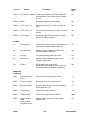
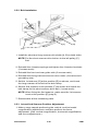
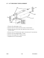
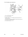
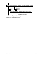
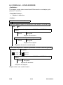
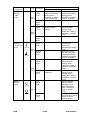
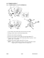
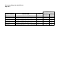
3. DRIVE LAYOUT
1
26
22
23
25
24
2
21
3
20
19
5
10
18
11
13
12
6
17
7
8
16
14
9
1
4
15
10
FT5733/5433
2-4
FSM
1: Main Motor Pulley
3: Fusing Drive Belt
2: Drum Drive Belt
26: Development Drive
Belt
4: Drive Distribution
Gear/Pulley
25: Drum Drive Pulley
24: Development Drive
CL Pulley
Drum
23: Drive Distribution Belt
Cleaning drive Gear
Cleaning Unit
12: Drive Distribution
Gear/Pulley
Development
9: Fusing Unit
Drive Gear
Fusing
20: Toner Supply Drive
Gear/Pulley
6: Copier Exit Roller
Gear
22: Toner Supply
CL Gear
7: Duplex Transport
Drive Belt
21: Development Unit
Shift Gears
8: Duplex Transport
Roller Pulley
10: Registration CL Gear
11: Upper Paper Feed
13: Feed Relay CL Gear
5: Sorter Adapter Gears
17: Relay Roller
19: Paper Feed
Drive
16: Paper Feed
Drive Belt
18: By-pass Feed
CL Gear
14: Lower paper
Feed CL Gear
FSM
15: Tray Unit drive
Gear
2-5
FT5733/5433
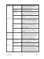
4. ELECTRICAL COMPONENT
DESCRIPTION
Refer to the electrical component layout on the reverse side of the
Point to Point (Water proof paper) for symbols and index numbers.
Symbol
Name
Function
Index
No.
Motors
M1
Main
Drives the main unit components.
1
M2
Exhaust blower
Blows the ozone built up around the
charge section through the ozone
filter.
6
M3
Upper tray lift
(non-duplex
machine only)
Raises the bottom plate in the upper
paper tray.
31
M4
Lower tray lift
Raises the bottom plate in the lower
paper tray.
28
M5
Transport fan
Provides air flow to the transport
section so that paper is held on the
transport guide. Also the air flow
isolates the toner collection tank from
fusing heat.
Provides air flow to the charge
corona section as well.
65
M6
Fusing exhaust
fan
Removes the heat from around the
fusing unit.
66
M7
Scanner drive
Drives the 1st and 2nd scanners (dc
stepper).
67
M8
3rd scanner
drive
Drives the 3rd scanner (dc stepper).
75
M9
Optics cooling
fan
Removes heat from the optics unit.
77
M10
Lens drive
Positions the lens.
100
M11
Duplex feed
(duplex
machine only)
Drives the feed roller and moves the
bottom plate up and down (24 V dc
stepper).
103
M12
Jogger (duplex
machine only)
Drives the jogger fences to square
the paper stack in the duplex tray (dc
stepper).
107
FT5733/5433
2-6
FSM
Symbol
M13
Name
LCT lift
Function
Index
No.
Lifts up and lowers the LCT bottom
plate.
79
PCB1
dc power supply Drives the exposure and fusing
lamps and rectifies 100 Vac or
220/230/240 Vac input and outputs
dc voltages.
44
PCB2
Main control
Controls all copier functions both
directly and through the other control
boards.
10
PCB3
Scanner motor
control
Controls the speed of the scanner
drive motor.
69
PCB4
Main motor
control
Controls the rotation of the main
motor.
71
PCB5
Operation panel
Controls the LED matrix, and
monitors the key matrix.
93
PCB6
ADS sensor
Senses the background density of
the original.
90
PCB7
High voltage
supply - CTBG
Supplies high voltage for the charge
corona, grid bias, transfer corona,
and development bias.
9
PCB8
High voltage
supply - D
Supplies high voltage for the
separation corona.
8
PCB9
PTL/QL
stabilizer
Provides high voltage for the
quenching and pre-transfer lamps.
73
PCB10 Duplex control
(duplex
machine only)
Controls the rotation of the duplex
feed motor.
106
PCB11 LCT interface
(LCT machine
only)
Interfaces the LCT control signal
between the main control board and
the LCT.
80
PCB12 Guidance
display control
(duplex
machine only)
Controls the guidance display board.
92
PCB13 Guidance
display (duplex
machine only)
Displays guidance for machine
operation.
94
Circuit Board
FSM
2-7
FT5733/5433
Symbol
Name
PCB14 Interface - type
G (option for
sorter stapler
and menu
reader)
Function
Index
No.
Interfaces the sorter stapler and
menu reader with the main control
board.
16
Switches
SW1
Upper paper
size - 1
(non-duplex
machine only)
Determines what size paper is in the
upper paper tray.
2
SW2
Upper paper
size - 2
(non-duplex
machine only)
Determines what size paper is in the
upper paper tray.
3
SW3
Upper paper
size - 3
(non-duplex
machine only)
Determines what size paper is in the
upper paper tray.
4
SW4
Upper paper
size - 4
(non-duplex
machine only)
Determines what size paper is in the
upper paper tray.
5
SW5
Lower paper
size - 1
Determines what size paper is in the
lower paper tray.
36
SW6
Lower paper
size - 2
Determines what size paper is in the
lower paper tray.
34
SW7
Lower paper
size - 3
Determines what size paper is in the
lower paper tray.
33
SW8
Lower paper
size - 4
Determines what size paper is in the
lower paper tray.
32
SW9
Color detection
Detects if color development unit is
set or not and which color toner
development unit is installed.
13
SW10 Exit cover
(Duplex
machine only)
Cuts the ac power line.
64
SW11 Platen cover
Informs the CPU when the platen
cover is closed.
88
FT5733/5433
2-8
FSM
Symbol
Name
Function
Index
No.
SW12 Front door safety Cuts the ac power line through RA1
and detects if the front door is open
or not.
91
SW13 Main
Supplies power to the copier.
95
SW14 LCT cover - 1
Detects if the LCT cover is open or
not.
83
SW15 LCT cover - 2
Cuts the dc power line of the LCT lift
motor.
84
SW16 LCT down
Sends a signal to the CPU to lower
the LCT bottom plate.
85
Lamps
L1
Quenching
Neutralizes any charge remaining on
the drum surface after cleaning.
47
L2
Pre-transfer
Reduces the charge on the drum
surface before transfer.
49
L3
Fusing
Provides heat to the hot roller.
60
L4
Exposure
Applies high intensity light to the
original exposure.
99
L5
Erase
Eliminates the charge for
unnecessary areas of the image on
the drum surface before exposure.
48
Magnetic
Clutches
MC1
Development
drive
Drives the development roller.
11
MC2
Toner supply
Drives the toner supply roller.
14
MC3
By-pass feed
Starts paper feed from the by-pass
feed table or LCT.
17
MC4
Feed relay
Drives the relay rollers.
19
MC5
Registration
Drives the registration rollers.
20
No.
MC6
Upper paper
feed
(non-duplex
machine only)
Starts paper feed from the upper
paper tray.
22
FSM
2-9
FT5733/5433
Symbol
MC7
Name
Lower paper
feed
Function
Index
No.
Starts paper feed from the lower
paper tray.
24
Solenoids
SOL1
Development
unit change
Changes the position of the black
development unit and color
development unit.
12
SOL2
Pick-up roller
Picks paper up from the by-pass
feed table or LCT.
18
SOL3
Duplex tray lock
(duplex
machine only)
Locks the duplex tray in the main
copier.
29
SOL4
Upper tray lock
(non-duplex
machine only)
Locks the upper paper tray in the
main copier.
39
SOL5
Lower tray lock
Locks the lower paper tray in the
main copier.
37
SOL6
Junction gate
(duplex
machine only)
Moves the junction gate to direct
copies to the duplex tray or to the
paper exit.
43
SOL7
Duplex turn
gate (duplex
machine only)
Moves the duplex turn gate to direct
copies to the duplex tray or to the
relay rollers.
105
Sensors
S1
By-pass feed
table
Detects if the by-pass feed table is
open or closed.
15
S2
Upper tray set
(non-duplex
machine only)
Detects if the upper paper tray is set
or not.
21
S3
Lower tray set
Detects if the lower paper tray is set
or not.
26
S4
By-pass feed
paper end
Informs the CPU that there is no
paper in the by-pass feed table.
53
S5
Upper tray
paper end
(non-duplex
machine only)
Informs the CPU when the upper
paper tray runs out of paper.
23
FT5733/5433
2-10
FSM
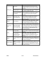
Symbol
Name
Function
Index
No.
S6
Lower tray
paper end
Informs the CPU when the lower
paper tray runs out of paper.
25
S7
Upper tray
upper limit
(non-duplex
machine only)
Detects the upper position of the
paper stack in the upper tray to stop
the upper lift motor.
30
S8
Lower tray
upper limit
Detects the upper position of the
paper stack in the lower tray to stop
the lower lift motor.
27
S9
Lower relay
Detects the lead edge of paper from
the lower paper tray to determine the
stop timing of the lower paper feed
clutch and detects misfeeds.
51
S10
Upper relay
Detects the lead edge of paper from
the upper paper tray to determine the
stop timing of the upper paper feed
clutch and detects misfeeds.
50
S11
Registration
Detects the lead edge of paper to
determine the stop timing of the feed
relay clutch and detects misfeeds.
52
S12
Image density
(ID)
Detects the density of the ID sensor
pattern on the drum to control the
toner density.
57
S13
V
Detects the VR and VL patterns.
58
S14
Fusing exit
Detects misfeeds.
62
S15
Junction gate
(duplex
machine only)
Detects misfeeds.
63
S16
Scanner H.P.
Informs the CPU when the 1st
scanner is at the home position.
68
S17
Lens H.P.
Informs the CPU when the lens is at
the full-size position.
72
S18
Platen position
Informs the CPU when the platen
cover is positioned. When the angle
between, the platen cover and the
exposure glass is about 30 degrees.
74
S19
3rd scanner H.P. Informs the CPU when the 3rd
scanner is in the full size position.
FSM
2-11
76
FT5733/5433
Symbol
Name
Function
Index
No.
S20
Original length
Detects the original length.
89
S21
Original width
Detects the original width.
96
S22
Duplex entrance Detects misfeed.
(duplex
machine only)
109
S23
Duplex turn
gate (duplex
machine only)
Detects the trail edge of paper to
determine the reverse timing of the
duplex motor and detects misfeed.
101
S24
Duplex paper
end (duplex
machine only)
Detects copy in the duplex tray.
102
S25
Jogger H.P.
(duplex
machine only)
Detects if the jogger fences are at
home position.
108
S26
LCT paper end
(LCT machine
only)
Informs the CPU when the LCT runs
out of paper.
82
S27
LCT lower limit
(LCT machine
only)
Sends signal to CPU to stop lowering
the LCT bottom plate.
81
S28
LCT upper limit
(LCT machine
only)
Sends signal to CPU to stop lifting up
the LCT bottom plate.
78
H1
Drum
Turns on when the main switch is off
to prevent moisture around the drum.
54
H2
Turns on when the main switch is off
Optics
anti-condensation to prevent moisture from forming on
the optics.
(option)
97
H3
Upper tray
(option)
Turns on when the main switch is off
to keep paper dry in the upper paper
tray.
55
H4
Lower tray
(option)
Turns on when the main switch is off
to keep paper dry in the lower paper
tray.
87
Heaters
FT5733/5433
2-12
FSM
Symbol
Name
Function
Index
No.
Thermistor
TH1
Drum
Monitors the temperature around the
drum.
56
TH2
Fusing
Monitors the temperature of the hot
roller.
59
TH3
Optics
Monitors the temperature of the
optics cavity.
98
TH4
Duplex motor
(duplex
machine only)
Monitors the temperature of the
duplex motor.
104
Provides back-up overheat
protection in the fusing unit.
61
Provides overheat protection in the
optics unit.
70
Removes electrical noise.
40
Thermofuse
TF1
Fusing
Thermoswitch
TS1
Optics
Noise filter
NF1
Fuse
FU1
Main (115 V
machine only)
Provides back-up high current
protection in the electrical
components.
42
FU2
Sorter line (115
V machine only)
Provides back-up high current
protection in the electrical
components of the sorter.
46
FU3
DF line (115 V
machine only)
Provides back-up high correct
protection in the electrical
components of the ARDF.
7
Provides back-up high current
protection in the electrical
components.
41
Circuit Breaker
CB1
FSM
(230 V machine
only)
2-13
FT5733/5433
Symbol
Name
Function
Index
No.
Relay
RA1
Main power
Controls main power.
45
Steps down the wall voltage to 100 V
ac.
38
Keeps track of the total number of
copies made.
86
Transformer
TR1
Main
Counter
CO1
Total
FT5733/5433
2-14
FSM
SECTION 3
INSTALLATION
1. INSTALLATION REQUIREMENT
1.1 ENVIRONMENT
1. Temperature Range: 10oC to 30oC (50oF to 86oF)
2. Humidity Range: 15% to 90% RH
3. Ambient Illumination: Less than 1,500 lux (do not expose to direct
sunlight)
4. Ventilation: Minimum space 20 m3. Room air should turn over at
least 30 m3/hr/person.
5. Ambient Dust: Less than 0.15 mg/m3 (4 x 10⁻⁶ oz/yd3)
6. If the machine location is air-conditioned or heated, place the
machine:
a)
where it will not be subjected to sudden
temperature changes.
b)
where it will not be directly exposed to cool
air from an air-conditioner in the summer.
c)
where it will not be directly exposed to
reflected heat from a space heater in winter.
7. Avoid placing the machine in an area filled with corrosive gas.
8. Avoid any places higher than 2,000 meters (6,500 feet) above
sea level.
9. Place the machine on a strong and level base.
10. Avoid any area where the machine may be frequently subjected
to strong vibration.
FSM
3-1
FT5733/5433
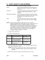
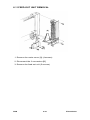
1.2 MACHINE LEVEL
1. Front to back level: within 5 mm (0.2")
2. Right to left level: within 5 mm (0.2")
Use a carpenter’s level to level the machine
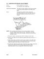
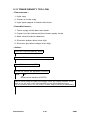
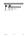
1.3 MINIMUM SPACE REQUIREMENTS
Copier only
Full system
a
e
h
f
d
c
b
g
a: more than 10 cm/3.9"
(When the micro sorter is
installed: 15 cm/5.9")
e: more than 10 cm/3.9" (When the
micro sorter is installed: 15
cm/5.9")
b: more than 40 cm/15.7"
f: more than 40 cm/15.7"
c: more than 80 cm/31.5"
g: more than 80 cm/31.5"
d: (When you use the copy
tray): more than 30
cm/11.8"
h: more than 20 cm/11.8" (When
the sorter stapler is installed: 10
cm/3.9")
NOTE: When the micro sorter is equipped, make sure there is at
least 15 cm (6.0") clearance on the back side, in order to
avoid damaging the sorter when it is opened.
FT5733/5433
3-2
FSM
1.4 POWER REQUIREMENTS
1. Input voltage level:
110V/60Hz
115V/60Hz
220V/230V/240V/50Hz
220V/60Hz
: More than 15A (for Taiwan)
: More than 15A (for N.A.)
: More than 8A (for EU.)
: More than 8A
2. Permissible voltage fluctuation: ±10%
3. Do not set anything on the power cord.
NOTE: a) Make sure the plug is firmly inserted in the outlet.
b) Avoid multi-wiring.
FSM
3-3
FT5733/5433
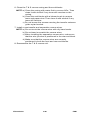
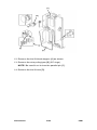
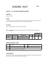
2. COPIER INSTALLATION
2.1 COPIER INSTALLATION
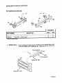
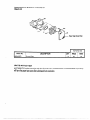
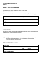
2.1.1 Accessory Check
1. Receiving Tray................................................................. 1
2. Outer Decal - Symbol Explanation .................................. 1
3. Sorter Key Top and Cover............................................... 1
4. Counter Set Key (--17 machine only) .............................. 1
5. Installation Procedure...................................................... 1
6. Operating Instructions (Except --27 machine) ................. 1
7. Now Equipment Condition Report
(--17, --19, --27, --29 machine only) .................................. 1
8. Envelope for NECR (--17 machine only) ......................... 1
9. User Survey Card (--17 machine only) ............................ 1
FT5733/5433
3-4
FSM
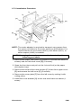
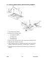
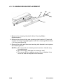
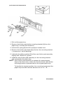
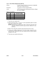
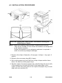
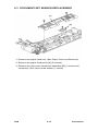
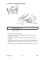
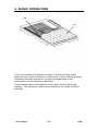
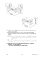
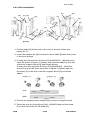
2.1.2 Installation Procedure
[A]
[A]
[B]
[G]
[H]
[F]
[E]
[C]
[A]
[D]
NOTE: Keep the shipping retainers after installing the machine.
They will be reused if in the future the machine is
transported to another location.
Proper reinstallation of the shipping retainers is required in
order to avoid any transport damage. It is important to
replace the scanner lock pins and the scanner lock plate
before transporting this copier. If it is not done, skewed
image may result.
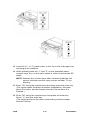
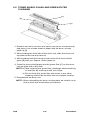
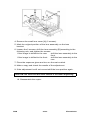
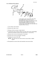
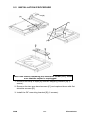
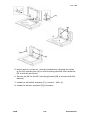
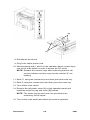
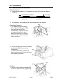
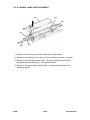
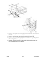
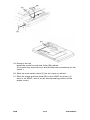
1. Remove the 7 strips of tape [A] as shown.
2. Open the front door and remove 4 strips of tape [B] as shown.
3. Pull out the paper tray [C], and remove a strip of tape [D] and the
foam block [E] (1 tray for the duplex machine and 2 trays for the
non-duplex machine).
4. Pull out the duplex tray [F] and remove the 2 strips of tape [G]
and 3 sheets of paper [H] (duplex machine only).
FSM
3-5
FT5733/5433
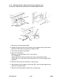
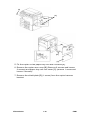
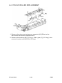
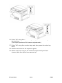
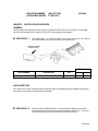
[A]
[D]
[B]
[C]
[E]
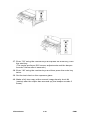
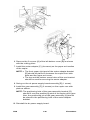
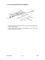
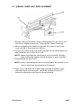
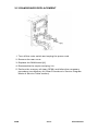
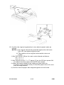
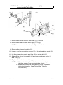
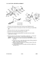
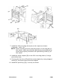
5. Remove the left scale [A] (2 shoulder screws).
6. Remove the scanner lock pin [B] simply by pulling it up from the
front and the rear side of the left scale bracket.
7. Reinstall the left scale.
8. Remove the left optics cover [C] (1 screw).
9. Remove the scanner lock plate [D] (1 screw) by pulling and lifting
it up and reinstall the left optics cover.
10. Remove the shipping retainer [E] holding the ozone filter. The
retainer is taped on the upper exit cover.
FT5733/5433
3-6
FSM
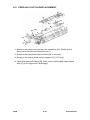
[B]
[C]
[A]
[C]
[D]
[E]
[F]
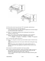
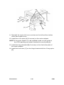
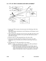
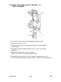
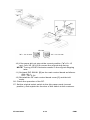
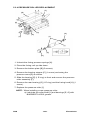
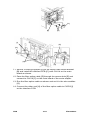
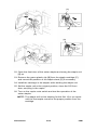
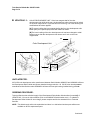
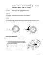
11. Push the development unit lock lever [A] to the right (to the lock
position).
12. Move the development release lever [B] to the right and pull out
the black development unit [C] half way. Holding the toner supply
unit [D] with your right hand and the bottom of the development
unit with your left hand, pull the unit all the way out . Place the unit
on a clean sheet of paper.
13. Separate the toner supply unit from the development unit (3
screws).
14. Pour one pack of black developer [E] into the development unit
while turning the development roller knob [F] counterclockwise.
This will distribute the developer inside the unit.
15. Remount the toner supply unit on the development unit.
FSM
3-7
FT5733/5433
Rev. 10/92
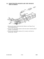
[B]
[C]
[A]
[D]
[E]
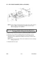
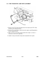
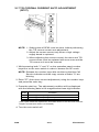
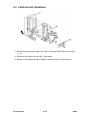
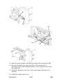
16. Lower the transfer & separation corona unit by pulling down the
release lever [A].
17. Turn the cleaning unit release lever [B] counterclockwise to the
upright position. (The cleaning unit is released from the drum.)
18. Remove the drum protective sheet [C] from the development unit
opening.
CAUTION: To avoid damaging the pick-off pawls, remove the
drum protective sheet by pulling the lower side as
shown in the figure.
19. Turn the cleaning unit release lever clockwise to the set position.
20. Remove the cleaning blade lock plate [D].
21. Reset the transfer & separation corona unit [E].
FT5733/5433
3-8
FSM
[E]
[B]
[C]
[A]
[C]
[D]
[F]
22. Install the black development unit [A] in the copier, and remove
the cover sheet [B] from the toner supply unit.
NOTE: • When installing the development unit, be sure that the
development unit rail is placed directly on the
development unit guide rail.
• Make sure that the development release lever [C] is in
its original position after the development unit is set.
23. Shake the toner cartridge [D] well from side to side. While
pushing the toner cartridge in, insert it halfway into the holder with
the seal [E] up.
24. As you peel off the seal, insert the cartridge completely. While
pushing the toner cartridge in, turn it counterclockwise until it
stops.
25. Slide out the charge corona unit [F] until it is fully extended and
push it back in to the original position. Repeat this action several
times.
FSM
3-9
FT5733/5433
[B]
[D]
[F]
[E]
[C]
[A]
26. Close the front door and set the copy tray [A].
NOTE: The following steps from 27 to 30 are required only to install
the optional platen cover [B].
27. Remove the rear cover (remove 2 screws and loosen 2 screws).
28. Install the 2 shoulder screws [C] on the top cover as shown.
29. Pass the harness [D] through the hole of the top cover and install
the optional platen cover (2 screws).
30. Couple the platen cover sensor connector [E] (3P white) with the
copier and reinstall the rear cover.
31. Stick the symbols explanation decal [F] on the top cover as
shown. (If the ARDF will be installed, stick the decal on the
corresponding position of the ARDF.)
32. If local voltage is 230 V or 240 V, perform the voltage change
procedure (following the installation procedure).
FT5733/5433
3-10
FSM
33. Load A3 (11" x 17") paper either in the 1st or the 2nd paper tray
and plug in the machine.
34. While pressing both the "1" and "3" on the operation panel
number keys, turn on the main switch in order to access the SP
mode.
NOTE: Release the number keys after confirming that the call
service indicator and the copy counter number "0" are
blinking.
35. Enter "65" using the number keys and then press the enter key.
(The copier starts the black developer initialization, this lasts
about 5 minutes, and the beeper sounds 5 times when it is
finished.)
36. Enter "66" using the number keys and press the enter key.
Press "1", then the enter key.
(The copier performs the drum initial setting and the beeper
sounds 5 times.)
FSM
3-11
FT5733/5433
37. Enter "54" using the number keys and press the enter key, then
the start key.
(The copier performs ID/V sensor adjustments and the beeper
sounds 2 times after 4 seconds.)
38. Enter "48" using the number keys and then press the enter key
twice.
39. Set the test chart on the exposure glass.
40. Make a full size copy at the manual image density level #4
(center) after the copier has warmed up (the beeper sounds 3
times).
FT5733/5433
3-12
FSM
41. Confirm that level 2 of the gray scale is just visible on the copy.
If the image density is not correct, go through the following steps.
(1) Press the enter key twice.
(2) Change the exposure lamp voltage data displayed in the
magnification ratio indicator. Use the number keys and follow
these rules:
If the image density is too dark:
increase the setting
If the image density is too light:
decrease the setting
NOTE: The data can be set between 50 and 75 in 0.5
steps.(The default setting is "63".)
(3) Press the enter key and then make a copy.
(4) Confirm if the image density is correct or not.
If not, repeat the above steps from (1) to (3).
NOTE: The initial exposure lamp voltage must be adjusted in this
step. If the adjustment is done after step 45 (the machine
performs the initial VL pattern detection), the reference
voltage for the exposure lamp voltage correction will be
wrong throughout the drum’s life.
FSM
3-13
FT5733/5433
42. Press the enter key and enter "56" using the number keys.
43. Press the enter key, then the start key.
(The copier performs the ADS sensor adjustment and the beeper
sounds 2 times after 4 seconds.)
44. Enter "12" using the number keys and press the enter key.
(duplex machine only)
45. Enter the number for the desired language on the guidance
display, and press the enter key. (duplex machine only).
1: English 2: French 3: German 4: Italian 5: Spanish
46. Turn the main switch off and on.
47. Enter "6" using the number keys and make copies in the full size
mode.
(The copier performs the VR sensor initial check during the copy
cycle.
When the copy cycle is finished, the copier performs the VL
sensor initial check by lighting the exposure lamp at the home
position.)
48. Check the machine operation and copy quality.
49. Tell the customers that this copier sometimes keeps turning on
the exposure lamp at the home position when copy jobs are
finished (the same phenomenon as in step 47).
This is normal for this copier, and this also helps maintain good
copy quality.
FT5733/5433
3-14
FSM
2.2 VOLTAGE CHANGE (220V to 230/240V)
[A]
[B]
[C]
NOTE: If the voltage of electrical power supply from wall outlets is
230V or 240V, the following procedure must be done
before plugging in the machine.
CAUTION: Make sure that the power cord of the machine is
unplugged before starting the following procedure.
1. Remove the rear cover (remove 2 screws and loosen 2 screws).
2. Swing out the dc power supply board assembly [A] (1screw).
3. Disconnect the 1P connector [B] of the ac main harness and
reconnect it to the appropriate voltage connector [C] of the main
transformer.
NOTE: Each 1P connector of the main transformer has its voltage
rating printed on it.
4. Reassemble the copier.
FSM
3-15
FT5733/5433
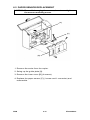
2.3 COLOR DEVELOPMENT UNIT INSTALLATION
(OPTION)
[A]
[B]
[D]
[E]
[C]
[F]
NOTE: This is a universal color development unit for red, blue, and
green developer and toner.
1. Install the appropriate color detection plate [A] on the rear bracket
of the color development unit. (The plate color corresponds to the
developer and toner color.)
2. Stick the appropriate color decal [B] on the development unit
handle.
3. Separate the toner supply unit [C] from the development unit ( 3
screws).
4. Pour one bag of color developer [D] into the development unit
while turning the development roller knob [E] counterclockwise.
This will distribute the developer evenly inside the unit.
5. Remount the toner supply unit on the development unit.
NOTE: When setting the toner supply unit, be sure that the 2
plates of the toner supply unit [F] fit in the positioning
grooves.
FT5733/5433
3-16
FSM
[A]
[B]
[C]
[D]
6. Shake the color toner cartridge [A].
7. Open the color toner supply unit cover [B] and set the color toner
cartridge on the color toner supply unit as shown.
8. Holding the center part of the cartridge, push down and pull out
the slide plate [C] until it stops.
9. Pull out the seal [D] until the red line is visible.
10. Gently tap the cartridge so that all the toner in the cartridge falls
inside the toner supply unit.
11. Return the slide plate to its original position and remove the
cartridge.
12. Close the color toner supply unit cover.
FSM
3-17
FT5733/5433
Rev. 11/92
13. Remove the copier rear cover (loosen 2 screws and remove 2 screws).
14. Swing the main control board assembly out (1 screw).
15. Install the color switch [A] on the color switch bracket [B] as illustrated.
16. Connect the color switch connector [C] to the DC harness (3P - brown).
17. Reassemble
FT5733/5433
3-18
FSM
Rev. 6/92
[C]
[A]
[B]
[D]
18. Open the copier front door.
19. While lifting the color development unit lock lever [A], pull out he
cover plate [B].
20. Holding the strap of the color development unit with your left
hand, hold the toner supply unit with your right hand, and insert
the development unit along the guide rails [C].
21. While lifting the color development unit lock lever, push the unit in
until it stops.
22. Stick the decal [D] on the copier front door as shown and close
the copier front door.
23. While pressing both "1" and "3" on the operation panel number
keys, turn on the main switch in order to access the SP mode.
NOTE: Release the number keys after confirming that the call
service indicator and the copy counter number "0" are
blinking.
24. Enter "10" using the number keys and then press the enter key.
(The copier starts the color developer initialization, this lasts about
1 minute, and the beeper sounds 5 times)
25. Turn the main switch off and on.
26. Check the color copy quality.
FSM
3-19
FT5733/5433
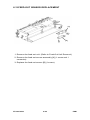
2.4 KEY COUNTER HOLDER INSTALLATION (OPTION)
[D]
[A]
[B]
[C]
[G]
[H]
[G]
[E]
[H]
[F]
CAUTION: Make sure that the main switch is turned off.
[Machines without LCT]
1. Remove the rear cover [A] (remove 2 screws and loosen 2
screws).
2. Open the by-pass feed table and remove the right upper cover [B]
(4 screws).
3. Remove the right lower cover [C] (2 screws).
-- Go to step 4.
[Machines with LCT]
1. Lift up the LCT top cover [D] and remove the LCT front cover [E]
(1 screw).
2. Remove the right front lower cover [F] (2 screws).
-- Go to step 4.
[Common procedure]
4. Remove the shorting connector [G] from the key counter
connector.
5. Remove the key counter cover [H] from the key counter holder
bracket
(2 screws).
FT5733/5433
3-20
FSM
[D]
[C]
[A]
[B]
[E]
6. Pass the 4P connector [A] of the key counter holder [B] through
the key counter holder access hole and couple it with the key
counter connector [C] of the copier.
7. Hold the fixing plate [D] on the inside of the key counter holder
bracket [E] and insert the key counter holder.
8. Align the holes in the fixing plate with the mounting holes of the
key counter holder and secure the key counter holder (2 screws).
NOTE: The fixing plate has three different hole sizes. Use the
holes that match those on the key counter holder that you
are installing.
9. Reinstall all the covers and check the key counter operation.
FSM
3-21
FT5733/5433
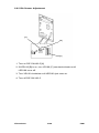
2.5 TRAY HEATER INSTALLATION (OPTION)
[B]
[C]
[E]
[A]
[F]
[D]
NOTE: The optional tray heaters keep copy paper dry. In humid
environments, copy paper may crease as it comes out of
the fusing unit. The heaters are available as service parts.
Required parts:
P/N A0699500: Tray Heater Kit --115V
P/N A0699501: Tray Heater Kit --230V
The contents of the
kits are as follows:
Tray heater
Tray heater bracket
Wire saddle
Philips pan head screw
Decal: High Temp.
2 sets
2 sets
1 piece
1 piece
1 piece
3 pieces
1 piece
CAUTION: Unplug the copier power cord before starting the
following procedure.
1. Open the copier front door.
2. Pull out the duplex tray [A] and remove the tray stopper brackets
[B], [C] on both side rails as shown (1 screw each), and then
remove the duplex tray from the copier [duplex machines only].
3. Pull out the paper tray [D] and remove the tray stopper brackets
[E], [F] on both sides as shown (1 screw each) and then remove
the paper tray from the copier [both paper trays for non-duplex
machines].
FT5733/5433
3-22
FSM
[A]
[E]
[B]
[G]
[F]
[D]
[C]
[H]
4. Remove the rear cover (remove 2 screws and loosen 2 screws).
5. Swing out the dc power supply board assembly [A] (1 screw).
6. Remove the main transformer assembly [B] (2 screws and 2
connectors).
7. Fix the tray heater [C] on the tray heater bracket [D] (2 screws),
and set the wire saddle [E] and the heater harness [F] on the
bracket as shown. Make 2 sets of this assembly.
[Upper tray heater]
8. Pass the heater harness through the upper heater access hole
[G] and install the tray heater assembly as shown (1 screw at the
front).
9. Connect the heater connector [H] with the copier as shown (2P
red).
FSM
3-23
FT5733/5433
[B]
[A]
[D]
[C]
[Lower tray heater]
10. Pass the heater harness [A] through the lower heater access hole
[B] and install the tray heater assembly as shown (1 screw at the
front).
11. Connect the heater connector [C] with the copier as shown (2P
red).
[Upper and Lower tray heaters]
12. Stick the warning high temp. decal [D] on the plate, to the right of
the tray heater bracket as shown.
13. Reassemble the copier.
14. Tell the customer that the copier main switch should be turned off
and the power cord should not be unplugged at night. Otherwise,
the tray heaters will not function.
FT5733/5433
3-24
FSM
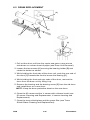
2.6 OPTICS ANTI-CONDENSATION HEATER
INSTALLATION (OPTION)
[E]
[D]
[B]
[C]
[A]
NOTE: The optional optics anti-condensation heater keeps water
from condensing on the copier’s mirrors. Such
condensation occurs under cold and high humidity
conditions, and causes the first few copies of the day to be
black or dark. The heater is available as a service part.
Required parts:
Optics
anti-condensation heater
Philips pan head screw
(M4 x 8)
(P/N AX400008 for 115V area,
P/N AX400009 for 220/230/240V
area)
(P/N 04340080W)
1 piece
2 pieces
CAUTION: Unplug the copier power cord before starting the
following procedure.
1. Open the front door and pull out the 1st and 2nd (or the paper
and duplex) trays.
2. Remove the left and front side screws [A] of the front upper cover
[B] and remove the left cover [C] (5 screws).
3. Remove the left scale [D] (2 shoulder screws) and the exposure
glass [E].
FSM
3-25
FT5733/5433
[A]
[D]
[C]
[E]
[B]
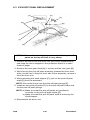
4. Move the 1st and 2nd scanners [A] to the left so that you can
access under the left scale bracket [B].
5. Install the optics anti-condensation heater [C] on the optics
bottom plate as shown with 2 screws.
6. Pass the heater connector [D] through the heater harness access
hole and connect it with the ac harness connector [E] (2P red) as
shown.
7. Reassemble the copier.
8. Tell the customer that the copier main switch should be turned off
and the power cord should not be unplugged at night. Otherwise.
the optics anti-condensation heater will not function.
FT5733/5433
3-26
FSM
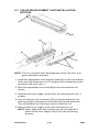
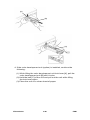
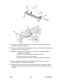
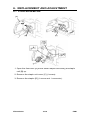
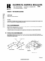
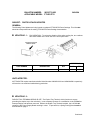
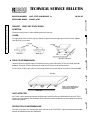
2.7 SORTER ADAPTER INSTALLATION (OPTION)
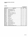
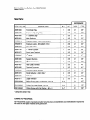
2.7.1 Accessory Check
1. Cover Bracket .................................................. 1
2. Gear Assembly ................................................. 1
3. Cover Plate....................................................... 1
4. Hinge Bracket .................................................. 1
5. Front Door ........................................................ 1
6. Hinge Pin .......................................................... 2
7. Philips Pan Head Screw M4 x 8 ....................... 10
8. Philips Pan Head Screw with Washer ............. 1
9. Installation Procedure....................................... 1
10. New Equipment Condition Report
(--17 machine only) ........................................... 1
FSM
3-27
FT5733/5433
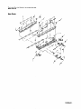
2.7.2 Installation Procedure
[A]
[G]
[D]
[C]
[F]
[C]
[B]
[E]
NOTE: The sorter adapter is required to transport copy papers from
the copier exit rollers to the sorter entrance guide plates. It is
required when the mini-sorter (A423), midi-sorter (A411), or
sorter stapler (A366) is installed.
CAUTION: unplug the copier power cord before starting the
following procedure.
1. Remove the copier rear cover [A] (remove 2 screws and loosen 2
screws) and the left small cover [B] (2 screws).
2. Open the front door and pull out the 1st and 2nd (or the paper
and duplex) trays.
3. Remove the left and front side screws [C] of the front upper cover
[D] and remove the left cover [E] (5 screws).
4. Remove the cover plate [F] from the left cover by cutting it with
cutting pliers.
5. Install the cover bracket [G] on the rear side frame as shown (1
screw).
FT5733/5433
3-28
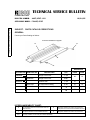
FSM
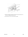
[A]
[D]
[B]
[C]
[H]
[F]
[E]
[G]
6. Remove the 2 corners [A] of the left bottom cover [B] as shown
with the cutting pliers.
7. Install the sorter adapter [C] (4 screws) on the paper exit section
of the copier.
NOTE: • The front upper right part of the sorter adapter bracket
[D] should be placed in-between the copier front side
plate and the upper exit cover.
• The top and the bottom screw holes of the rear bracket
should be used for securing the sorter adapter.
8. Swing out the dc power supply board assembly [E] (1 screw).
9. Install the gear assembly [F] (3 screws) on the copier rear side
plate as shown.
NOTE: The positioning hole of the gear assembly bracket [G]
should fit over the positioning stud of the copier drive gear.
Also, the positioning pin of the gear assembly [H] should
be placed in the positioning hole of the sorter adapter
bracket.
10. Reinstall the dc power supply board.
FSM
3-29
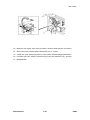
FT5733/5433
[D]
[A]
[C]
[B]
11. Reinstall the copier left cover and secure the left and front sides
of the front upper cover.
12. Install the cover plate [A] (2 screws) on the sorter adapter.
NOTE: If the sorter stapler is to be installed locate a mylar guide in
the ST22 packing and install it behind the cover plate [A].
13. Install the hinge bracket [B] (2 screws) on the front side plate of
the sorter adapter.
14. Install the front door [C] on the hinge bracket with the 2 hinge pins
[D].
FT5733/5433
3-30
FSM
SECTION 4
SERVICE TABLES
1. SERVICE REMARKS
1.1 HANDLING THE DRUM
The organic photoconductor drum is comparatively more sensitive to
light and ammonia gas than a selenium drum.
1. Never expose the drum to direct sunlight.
2. Never touch the drum surface with bare hands. When the drum
surface is touched with a finger or becomes dirty, wipe with a dry
cloth or clean with wet cotton. Wipe with a dry cloth after cleaning
with wet cotton.
3. Never use alcohol to clean the drum; alcohol dissolves the drum
surface.
4. Store the drum in a cool, dry place away from heat.
5. Take care not to scratch the drum as the drum layer is thin and is
easily damaged.
6. Never expose the drum to corrosive gases such as ammonia gas.
7. Always keep the drum in the protective sheet when keeping the
drum unit, or the drum itself, out of the copier. Doing so avoids
exposing the drum to bright light or direct sunlight. This will
protect the drum from light fatigue.
8. Before inserting or pulling out the drum unit, the following should
be performed to avoid damaging the drum:
a) Remove the black and color development units
b) Remove the cleaning unit
c) Remove the charge corona unit
d) Lower the T&S corona unit
9. Drum initial setting (SP66) must be performed when a new drum
is installed.
FSM
4-1
FT5733/5433
Rev. 10/92
1.2 DRUM UNIT
1. Make sure that the drum unit is set in position and secured with
the screw when the main switch is turned on. If the drum unit is
loose, poor contact of the drum connectors may cause electrical
noise, resulting in unexpected malfunction (RAM data change is
the worst case).
2. Clean the green color filter on the drum unit top plate with a dry
cloth and discharge static electricity by touching it with your
finger. Do not clean the filter with water or any other cleaning
solution as the filter has an antistatic coating.
1.3 CHARGE CORONA
1. Clean the corona wires by sliding the corona unit in and out. (The
cleaner pads come into contact with the corona wires when the
corona unit is slid all the way out.) The wires can be also cleaned
with water. Do not use sandpaper or a solvent.
2. Clean the charge corona casing with water first to remove NOx.
Then clean it with alcohol if any toner still remains on the casing.
3. Clean the end blocks with a blower brush first to remove toner
and paper dust. Then clean it with alcohol if any toner still
remains on it.
4. Do not touch the corona wires with oily bare hands. Oil stains
may cause white bands on copies.
5. Make sure that the corona wires are correctly positioned between
the cleaner pads and that there is no foreign material (iron filings,
etc.) on the casing.
6. When installing new corona wires, do not bend or scratch the
wire surface to avoid any uneven charge. Also be sure that the
corona wires are correctly positioned in the rear end block and
that the damper rings are correctly positioned in the front end
block. (See charge corona wire replacement.)
7. Clean the charge grid plate with a blower brush (not with a cloth).
8. Do not touch the charge grid plate with oily bare hands. Also, do
not bend the charge grid plate or make any dent on it. Doing so
may cause uneven charge.
9. The corona wire height should only be adjusted when the front
end block is replaced.
FT5733/5433
4-2
FSM
1.4 OPTICS
1. When installing the exposure glass, make sure that the red mark
on the edge of the glass faces up. This side has received a
special treatment to be smoother and generate less static
electricity. This is especially important when the ARDF is
installed.
2. When moving the 1st or 2nd scanners, always hold them at the
center. Move them slowly, carefully, and gently.
Abrupt movement may cause the belt to slip into the wrong
position on the scanner drive pulleys.
3. Do not bend or crease the exposure lamp flat cable. Be careful of
this especially when reinstalling the lens housing cover.
4. When reinstalling the lens housing cover, make sure that the light
shielding mylar on the original length sensor does not interfere
with the light path to the ADS sensor board.
5. Do not touch the following parts with bare hands:
a) Reflectors
b) Exposure lamp
c) Mirrors and lens
d) ID sensor and VL patterns
6. To clean the mirrors and lens, only use a clean soft cloth damped
with alcohol or water.
7. Do not adjust uneven exposure by changing the exposure lamp
position but by using the exposure adjusting plates. Adjusting the
lamp position is very difficult because the filament cannot be
seen clearly as the lamp is frosted.
8. Adjust the exposure lamp voltage (SP48) only when the drum
initial setting (SP66) is performed.
9. Do not remove the lens housing guide plate and the 3rd scanner
guide plate. They were positioned on the optics base plate with a
special jig at the factory.
FSM
4-3
FT5733/5433
1.5 ERASE LAMP
1. A narrower lead edge erase margin increases the possibility of
fusing jams. The margin should be at least 1.0 mm.
2. After cleaning the erase lamp unit, rub it lightly with your finger to
discharge any static electricity on the unit surface.
3. Make sure that the erase lamp setting (SP84) is correct.
Otherwise, ID sensor abnormal condition will occur.
1.6 DEVELOPMENT UNIT
1. Be careful not to nick or scratch the development roller sleeve.
2. Place the development unit on a sheet of paper after removing it
from the copier. This prevents any small metal objects (staples,
clips, E-rings, etc.) from being attracted to the development roller
and getting inside the unit.
3. Be careful not to bend the bias terminals.
4. Clean the drive gears after removing the used developer.
5. Never load different types of developer or toner (black and color)
into the development unit. Doing so will cause poor copy image
and toner scattering inside the copier.
6. Developer initialization is necessary when new developer is
loaded.
a) Black developer initialize (SP65)
b) Color developer initialize (SP10)
7. Adjust the black development bias voltage (SP37) together with
the exposure lamp voltage (SP48) if necessary. This should be
done only when the drum initial setting (SP66) is performed. The
results of adjusting the black bias voltage with the used drum will
be compensated by the exposure lamp voltage when the VL
pattern detections are performed. The color development bias
voltage (SP79) can be adjusted any time.
8. The doctor gaps must not be adjusted in the field as they are
strictly adjusted at the factory.
FT5733/5433
4-4
FSM
1.7 TRANSFER AND SEPARATION
1. Clean the T&S corona unit casing with water then with alcohol if
necessary.
2. Clean the separation corona wire only with dry cloth as it is
carbon coated.
3. Clean the end blocks with a blower brush and alcohol.
1.8 CLEANING UNIT
1. When servicing the cleaning unit, be careful not to damage the
edge of the cleaning blade.
2. Do not touch the cleaning brush with bare hands.
3. Before pulling out the cleaning unit, place a sheet of paper under
it to catch any toner falling from the unit.
4. Empty the used toner tank in the following cases:
a) At PM
b) When the used toner tank is filled more than half of its
capacity. (Of course it is better to do it at every visit.)
c) When an ID sensor abnormal condition happens. (Used toner
tank overflow cannot be detected.)
5. Perform the toner end counter clear (SP83) whenever the used
toner tank is emptied.
6. If the toner end counter (SP58) is cleared by accident (by SP83
or any other reason), empty the used toner tank.
1.9 PRE-TRANSFER AND QUENCHING LAMPS
1. When removing the PTL filter to clean it, take out the drum unit
first to prevent any damage on the drum.
2. When reinstalling the PTL filter, make sure that the filter is
correctly positioned.
3. After cleaning the quenching lamp filter, rub it lightly with your
finger to discharge any static electricity on the filter.
FSM
4-5
FT5733/5433
1.10PAPER FEED
1. Do not touch the pick-up, feed, separation rollers and the friction
pads with oily bare hands.
2. The side fences and the rear fence of the paper trays should be
positioned correctly to align with the actual paper size.
Otherwise, paper misfeeds may occur.
3. The friction pad should be replaced together with the friction pad
holder and pad entrance seal as an assembly.
4. The friction pad assembly and the paper feed roller should be
replaced as a set to maintain paper feed ability. (A worn out feed
roller will provide incorrect friction pad pressure.)
5. The friction pad holder mounting bracket must be reinstalled on
the original paper tray. Because the friction pad pressure is
adjusted for each paper feed station independently at the factory.
6. The paper tray with the friction pad mechanism must be
reinstalled at the original paper feeding station.
7. The friction pad pressure should not be adjusted in the field.
1.11FUSING UNIT
1. Be careful not to damage the edges of the hot roller strippers or
their tension springs.
2. Do not touch the fusing lamp with bare hands.
3. Make sure that the fusing lamp is positioned correctly and that it
does not touch the inner surface of the hot roller.
FT5733/5433
4-6
FSM
2. SERVICE PROGRAM MODE
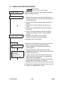
2.1 SERVICE PROGRAM MODE OPERATION
The service program (SP) mode is used to check electrical data,
change mode, and adjust settings.
2.1.1 Service Program Access Procedure
There are three ways to access the SP mode.
1: By key operation (for users and sales representatives).
2: By turning on the main switch while holding down number keys.
(for service representatives for normal SP modes).
3: By turning on the main switch while holding down mode keys (for
service representatives for memory all clear mode (SP99) and
normal SP modes).
Access Procedure 1: Key operation
Accessible SP mode numbers:
11, 14, 15, 16, 17, 18, 19, 20, 21, 26, 27, 34, 36, 38, 39, 46, 86, 91,
92, 93
(Refer to the SP mode table for details.)
1. Turn on the main switch.
2. Press the Clear Modes key.
3. Press the Clear/Stop key.
4. Press the Enter key.
NOTE: The Call Service indicator and the Copy Counter number
"0" start blinking to show that the SP mode has been
accessed.
5. Enter the desired SP mode number using the number keys and
press the Enter key.
FSM
4-7
FT5733/5433
NOTE:1. An SP mode number will blink in the copy counter. The
Copy Counter will stop blinking and stay on when the
Enter key is pressed.
2. When the SP mode number is blinking, it can be
changed by pressing the Clear/Stop key and entering a
new number. The SP mode number can also be
changed by using the Zoom keys ("+" & "--").
3. If the Enter key is pressed with an invalid SP mode
number, the Max indicator will blink and the Copy
Counter number will change to "0". In this case, Enter a
valid SP mode number and press the Enter.
6. To leave the SP mode, press the Clear Modes key.
Access Procedure 2: Main switch and number keys
Accessible SP mode numbers:
All SP mode numbers except SP99 (memory all clear).
1. Turn the main switch off.
2. While pressing both 1 and 3 on the operation panel number keys,
turn on the main switch.
NOTE: Release the number keys after confirming that the Call
Service indicator and the Copy Counter number "0" are
blinking.
3. Enter the desired SP mode number using the number keys and
press the Enter key.
NOTE:1. An SP mode number will blink in the Copy Counter.
The Copy Counter will stop blinking and stay on when
the Enter key is pressed.
2. When the SP mode number is blinking, it can be
changed by pressing the Clear/Stop key and entering
the new number. The SP mode number can also be
changed by using the zoom keys ("+" & "--").
3. If the Enter key is pressed with an invalid SP mode
number, the Max indicator will blink and the Copy
Counter number will change to "0". Enter a valid SP
mode number and press the Enter key.
4. To leave the SP mode, turn off the main switch.
FT5733/5433
4-8
FSM
Access Procedure 3: Main switch and mode keys
Accessible SP mode numbers:
All SP mode numbers including the SP99 (memory all clear)
1. Turn the main switch off.
2. While pressing both the Modes Clear and Clear/Stop keys on the
operation panel, turn on the main switch.
NOTE: Release the keys after confirming that the Call Service
indicator and the Copy Counter number "0" are blinking.
3. After that follow access procedure 2.
2.1.2 Change Adjustment Values or Modes
1. Follow steps1 to 5 of access procedure 1 or steps 1 to 3 of
access procedure 2.
2. The factory-set value/mode or the default setting will be
displayed in the three digit indicator.
3. Enter the desired value or mode using the number keys. (SP
mode numbers and information are given in the SP Mode table.)
4. To leave the SP mode, press the Clear Modes key (access
procedure 1) or turn off the main switch (access procedure 2).
2.1.3 Memory All Clear Procedure (SP99)
CAUTION: Memory all clear mode (SP99) clears all the
correction data for process control and software
counters, and returns all the modes to the default
settings. Normally, this mode should not be
performed.
This procedure is required only when the copier
malfunctions due to a damaged RAM or when
replacing the RAM board for any reason.
1. Access the SP mode through Access Procedure 3.
2. Enter "99" and press the Enter key.
3. Enter "1" and press the Enter key. (Beeper sounds 5 times when
memory has been cleared.)
FSM
4-9
FT5733/5433
4. Enter the factory-set values in the following SP modes:
40:
41:
42:
43:
44:
45:
47:
50:
62:
161:
162:
163:
164:
Jogger span (Duplex machine only)
Lead edge erase
Registration
Vertical magnification
Horizontal magnification
Duplex magnification (Duplex machine
only)
Focus adjustment
Lens error correction
Grid reference voltage
Grid volt/M-CH drum current check (P)
T-CH PWM/drum current check
D-CH (AC) PWM/drum current check
D-CH (DC) PWM/drum current check
NOTE: Open the front cover and remove the cover plate (1
screw) from the front upper cover. There is an SP data
table sheet inside the front upper cover which gives the
above factory-set values.
5. Turn off the main switch.
6. Clean the used toner tank because the toner end counter has
been cleared.
7. Replace the OPC drum with a new one.
NOTE: Since the drum counter for the process control has been
cleared, the old drum cannot be used. If the old drum is
used after all memory is cleared, a dirty background
and/or toner scattering will appear on copies sooner or
later because proper VG correction will not be applied to
the drum.
8. Clean the optics, sensors, and inside of the machine if necessary.
9. If the high voltage supply board - CTBG and/or -D has been
repalced, do the following:
1) Clean the corona unit casings and replace the
corona wires with new ones.
2) Enter to the SP mode by the access procedure 2.
3) Enter the grid voltage correction data in SP62
referring to the label on the high voltage supply
board - CTBG.
4) Perform the auto drum current adjustment by SP57.
10. Enter the SP mode using access procedure 2.
FT5733/5433
4-10
FSM
11. Enable optional equipment operation with SP71 (sorter), SP72
(paper tray unit), and SP84 (edit erase lamp unit) as necessary.
12. Perform the following SP modes:
SP66: Drum initialize
SP54: Auto Vsg/Vlg adjustment
SP48: Exposure lamp voltage adjustment
SP56: Auto ADS gain adjustment
13. Check copy quality and the paper path and do the necessary
adjustments.
FSM
4-11
FT5733/5433
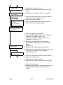
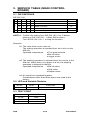
2.2 SERVICE PROGRAM MODE TABLE
NOTE:1. A "❐" after the mode name means that copies can be
made.
For these modes, the copier goes automatically into
copy mode when an SP mode number is selected by
pressing the "#" key, or when the data number for
adjustment is entered by pressing the "#" key after
selecting the SP mode number.
To make copies, enter desired copy quantity, select ID
level and paper tray, then press the Start key.
If you do not wish to make copies, press the "#" key
instead of the Start key.
2. A "•" before the mode number means that the mode
can be accessed by users and sales representatives.
3. In the Function column, comments (extra information)
are in italics.
4. In the Data column, the default value is printed in bold
letters.
Mode No.
2
Free Run Set
3
Free Run Reset
❐
4
Forced Start ❐
5
Lamp OFF ❐
6
No Misfeed
Detection ❐
7
Call Service
Indicator
8
Input Check ❐
9
Output Check
FT5733/5433
Function
Sets the copier in free run mode.
(The copier runs without paper feeding.
After SP2 is set, press the start key to
start free run operation.
Before pressing the start key you can
select any other SP mode in which
copying is possible [❐ mark].
["#"→SPNo.→"#"→Start key].)
Data
Resets the copier from free run mode.
Copies can be made before being
warmed up.
(Copy quality and paper transport are
not assured.)
Copies are made with exposure lamp
OFF.
(Black copies are made.)
Copies are made without ON check of
jam detection.
Indicates the cause of a blinking call
service indicator.
(Indicates 0, 1, 2, 3, 12, 13, 23, or 123
in the three digit indicator.)
0: Normal
1: PM
2: ID sensor
failure
3: Toner
overflow.
Displays the input data from sensors
and switches.
(For data, see page 4 - 28.)
Electrical components turn on.
(For data, see page 4 - 31.)
4-12
FSM
Mode No.
10
•11
12
Function
Agitates new color developer for about
1 minute.
Press the start key to begin operation.
Color Developer
(This must be done when new color
Initialize
developer is put in.
Beeper sounds 5 times when
initialization is completed.)
Turns on all the indicators on the
operation panel.
All Indicators ON
(To turn off the indicators, press the "#"
key.)
Language
Selects the language displayed in the
guidance display.
(SP12 applies to type 2 copiers only.
For other languages the optional ROM
is required.)
Selects single or double count for the
total counter and key counter in 11" x
17" copying.
(Double count is not applied for copies
from the by-pass feed table.
Double count is applied to the user
code counter [SP91] and the
mechanical counters.)
Selects accessible period for manual
stapling after completing a copy job in
sort mode.
(Only when the sorter stapler is
installed.)
Data
0: Japanese
1: English
2: French
3: German
4: Italian
5: Spanish
[Other
Languages]
0:
1:
2:
3:
4:
5:
13
DLT Double
Count
•14
Manual Staple
Reset
•15
Auto Reset
Selects auto reset time of 1 or 3
minutes, or cancels this mode.
•16
Count Up/Down
Selects count up or count down.
•17
Auto Cassette
Shift
Selects auto cassette shift mode.
(Copier automatically shifts to the LCT
or paper tray holding the same size
paper when paper runs out.)
0: Yes
1: No
•18
Beeper On
Turns beeper on or off.
0: On
1: Off
ID Mode
Specifies whether the copier defaults to
0: ADS
ADS or manual ID mode when the
1: Manual
main switch is turned on.
•19
FSM
4-13
0: Single
1: Double
0: 20 sec.
1: 1 min.
2: None
0: 1 min.
1: 3 min.
2: None
0: Up
1: Down
FT5733/5433
Rev. 6/93
Mode No.
•20
•21
22
23
24
25
•26
•27
28
29
30
31
32
Data
0: On
LCT Priority
1: Off
0: APS
APS Priority
1: Manual
(Copier)
2: No
0: 5 sec.
SADF Auto Reset Selects auto reset time for SADF mode.
1: 60 sec
Enables originals of various sizes to be
fed from the same width stack.
1: Yes
ADF Free Size
(When this mode is enabled, the job
0: No
interval for each original increases.)
Makes a white frame on the border line
Overlay Border
when using "Black in area" or "Color in 0: No
Erase
area" mode.
1: Yes
(Only when the editor is installed.)
Sets the staple limit of copies in each
0: Yes (30
bin in staple mode.
copies)
Staple Limit
(Only when the sorter stapler is
1: No (50
installed.)
copies)
Selects the priority of APS mode when
0: Yes
Auto APS Select
originals are set on the ADF.
1: No
(ADF)
(Only when the ADF is installed.)
Sets the priority of series copying in
0: No
Overlay Series
overlay mode.
1: Yes
Priority
(For type 2 copiers only)
Sort Mode is automatically selected
when more than 1 original is set on the
ADF and the entered copy quantity is
greater than 1 and less than 21 (11 for
0: Manual
Auto Sort Select the micro sorter).
1: Auto Sort
(Sorter and ADF must be installed on
(ADF)
the machine.
When in duplex 1 [1-sided original
mode] or overlay mode, more than 2
originals must be set.)
Selects fusing temperature control
0: Yes
mode.
(Zero
Zero Cross
(After selecting the control mode and
cross)
Control
turning the main switch off/on, the
1: No
fusing temperature control mode
(Phase)
changes.)
Selects black toner supply mode.
0: Detect
Black Toner
(See SP 31/SP32 for toner supply
Mode
Supply Mode
1: Fixed Mode
amount.)
0: 15%
Black Toner
1: 7%
Determines how much toner is
Supply Ratio
supplied in detect mode.
2: 30%
(Detect Mode)
3: 60%
0: 7.0%
Black Toner
1: 3.5%
Determines how much toner is
Supply Ratio
supplied in fixed mode.
2: 10.5%
(Fixed Mode)
3: 14.0%
FT5733/5433
Function
Sets the feed station priority to LCT or
the 1st tray.
Specifies whether the copier defaults to
APS or manual mode when the main
switch is turned on.
4-14
FSM
Mode No.
33
•34
35
•36
37
Function
Sets the bias voltage applied to the
development roller for the ID sensor
pattern.
Black (ID sensor)
(0: --200 V= Normal
Pattern Bias
1: --160 V= Lighter
2: --220 V= Darker
3: --240 V= Darkest)
Selects the image density level in ADS
mode.
(Data 1: Increases charge grid voltage
[--50 V]. Development bias voltage has
ADS Density
standard value.
Data 2: Increases development bias
voltage [--40 V]. Charge grid voltage
has standard value.)
Black ID sensor check is performed
every 5 copies or 10 copies.
Black ID
(If low image density occurs in the
Detection
toner near end condition, change the
data to "1".)
Selects the margin on the right side of
the reverse page in duplex 1 mode.
Image Shift
(For type 2 copier only. When duplex 1
(Duplex 1)
[1-sided original mode] is selected, this
margin is automatically added.)
Adjusts black bias voltage if the image
density at level 4 cannot be adjusted
by (SP48 exposure lamp voltage).
This must be done only after replacing
the OPC drum.
Black Bias
(0: Vo
= Normal
1: Vo +40 V = Darkest
2: Vo +20 V = Darker
3: Vo --20 V = Lighter
4: Vo --40 V = Lightest)
•38
Edge Erase
Selects the width of the edge erase
margin.
(Only when the editor is installed.)
•39
Center Erase
Selects the width of the center erase
margin.
(Only when the editor is installed.)
40
41
42
FSM
Adjusts the stop position of the jogger
fences.
Jogger Span
(For type 2 copier only. 0.5 mm per
step. [max, --4.0 mm to +3.5 mm].)
Adjusts lead edge erase margin.
Lead Edge Erase
(0.5 mm per step [max --4.0 mm to
❐
+3.5 mm].)
Adjusts lead edge registration.
Registration ❐
(0.5 mm per step [max --4.0 mm to
+3.5 mm].)
4-15
Data
0: N
1: L
2: H
3: HH
0: N (Normal)
1: H (Darker)
2: L (Lighter)
0: 10 copies
1: 5 copies
0: 5 mm
1: 0 mm
2: 10 mm
3: 15 mm
0: N
1: HH
2: H
3: L
4: LL
0: 10 mm
1: 5 mm
2: 15 mm
3: 20 mm
0: 20 mm
1: 10 mm
2: 15 mm
3: 25 mm
0~15
8 = default
0~15
8 = default
0~15
8 = default
FT5733/5433
Mode No.
43
Vertical
Magnification ❐
44
Horizontal
Magnification ❐
45
•46
47
48
Duplex
Magnification
Function
Adjusts magnification in the paper
travel direction.
(0.2 % per step. [max. --1.6% to
+1.4%].)
Adjusts magnification perpendicular to
the direction of paper travel.
(0.2 % per step. [max. --3.2% to
+3.0%].)
Adjusts vertical magnification of the
first image to equal the second image
when using overlay or duplex mode.
Selects the development bias voltage
of manual ID level 7.
Highlight Bias
(0: --240 V = Normal
(Manual ID Level
1: --200 V = Darker
7)
2: --280 V = Lighter
3: --320 V = Lightest)
Adjusts the 4th/5th mirror position to
correct the fine focus.
Focus
(0.6 mm per pulse. SP47 must be done
after vertical and horizontal
Adjustment ❐
magnification adjustments [SP43 and
44].)
Adjusts the exposure lamp voltage.
(50 to 75 V in 0.5 V steps.
Lamp Voltage ❐ The lamp voltage must be adjusted
only after performing SP 66 when
replacing the OPC drum.)
49
Fusing
Temperature
50
Lens Error
Correction ❐
51
Lamp Voltage
Check
FT5733/5433
Adjusts fusing temperature.
(175 to 190 °C in 1 °C steps.)
Data
0~15
8 = default
0~31
16 = default
0: +0.4%
1: No
correction
2: +0.2%
3: +0.6%
4: +0.8%
5: +1.0%
6: +1.2%
7: +1.4%
8: +1.6%
9: +1.8%
10: +2.0%
0: N
1: D
2: L
3: LL
0~80
40 = default
50~75V
63V = default
175~190 °C
185 ° =
default
Adjusts the lens position to correct
magnification in enlarge/reduction
0~15
mode.
8 = default
(0.1% per step [max. --0.8%, to +0.7%].)
Displays the exposure lamp voltage.
(The exposure lamp, main motor,optics
cooling fan fusing exhaust fan, and
exhaust blower turn on for 10 seconds
when the Enter key is pressed.
[V]
Press the "•" key to check the target
lamp voltage (including corrections).
Press the C/S key to turn this mode off.
Do not repeat more than 5 times to
avoid overheating the optics cavity.)
4-16
FSM
52
53
Mode No.
Fusing
Temperature
Check ❐
Drum
Temperature
Check ❐
54
Auto Vsg/Vlg
Adjustment ❐
55
Vsp/Vsg Data ❐
56
Auto ADS Gain
Adjustment
57
Auto Drum
Current
Adjustment
58
Toner End
Counter Check
FSM
Function
Data
Displays the fusing temperature.
[°C]
Displays the temperature around the
drum.
[°C]
Adjusts Vsg of ID sensor and Vlg of V
sensor automatically at once.
(Adjusted PWM values of ID sensor
and V sensor are displayed in the three
digit indicator.
Beeper sounds 2 times when the
adjustments [about 4 sec.] are
completed.)
Displays the Vsg and Vsp readings.
The Vsg reading is displayed while the
"0" key is held down.
(When making copies, the Vsp and
[V]
Vsg voltage readings are updated
every 10 or 5 copies [ID sensor check
timing].)
Adjusts ADS gain data automatically
when the start key is pressed.
(Close the platen cover to prevent
external light from reaching the ADS
sensor when performing this
adjustment.
The gain data is displayed in the three
digit counter.
Beeper sounds 2 times when the
adjustment [about 4 sec.] is completed.)
[Display only]
1: Measuring
Adjusts the transfer and separation
and adjusting
corona currents automatically.
the transfer
Press the start key to perform.
corona
(When the high voltage supply board
[CTBG] and/or [D] is replaced, perform current.
this mode after setting the data of
2: Measuring
SP62.
and adjusting
When separation corona current
adjustment fails, beeper sounds twice the
separation
and the copier tries the adjustment
corona
again.
current.
Beeper sounds twice when the
adjustment is completed.)
3: Completed
Displays the contents of the black toner
end counter.
(Toner end condition is not counted if
the toner end condition happens within
250 copies after the previous toner end
condition.)
4-17
FT5733/5433
Mode No.
59
Bias Voltage
Check ❐
62
Grid Reference
Voltage
65
Black Developer
Initialize
66
Drum Initialize
67
68
69
70
Drum Correction
Level (VR)
Function
Displays bias voltage. Press the Start
key to display the bias voltage. Press
the C/S key to stop.
Sets the grid voltage correction data to
correct the output from the high voltage
supply board.
(A label on the high voltage supply
board gives the correct value.
When the high voltage supply board
[CTBG] is replaced, set the data using
SP62 before performing SP57.)
Agitates new black developer for about
5 minutes.
Press the start key to begin operation.
(This mode must be done when new
black developer is put in.
Beeper sounds 5 times when the
initialization is completed.)
Used to set new drum condition.
(This must be done when a new drum
is installed. The OPC counter, VR
correction level, and Vref [initial
Vlp/Vlg] are cleared.
To set, press "1" then the "#" key.
Beeper sounds 5 times when the
initialization is done.)
Displays the present VR correction
level.
(VR level [%]=Vrp/Vrg x 100)
Displays the present Vdat. [Vlp/Vlg x
100=Vdat]
The VL level (%) is displayed while the
Lamp Correction
"•" key is held down.
Level (VL)
(VL level [%]=Vdat/Vref x
100=[(Vlp/Vlg)/
(Initial Vlp/Vlg)] x 100.)
Detects VR correction level regardless
of the drum counter.
Sensed Drum
Correction Level (The detection will be done in the first 5
(VR) (Forced VR copy cycles after exiting the SP mode.
Detection)
Beeper sounds 5 times when this
mode is accepted.)
Detects VL correction level regardless
of the drum counter.
(VL pattern detection is done 4 times.
Sensed Lamp
Correction level Beeper sounds for each detection and
(VL) (Forced VL Vdat is displayed in the three digit
Detection)
indicator each time.
The average of the 4 detections can be
monitored by SP68.)
FT5733/5433
4-18
Data
[V]
704
0: NO
1: YES
[Display only]
0: 100-84
1: 83-58
2: 57-41
3: 40-28
4: 27-0
[Display only]
VL level
0-100 : +1V
101-150 : 0V
151: --1V
FSM
Mode No.
Function
Enables sorter operation
(0: No sorter
1: N/A
2: Mini sorter (CS2090)
3. N/A
4: Sorter stapler (ST22)
5: Sorter adapter).
71
Sorter
72
Option Paper
Tray Unit
Enables paper tray unit operation.
73
LCT Paper Size
Selects paper size for the LCT.
(For type 2 and type 3 only)
74
Color ID
Detection
75
76
77
79
81
FSM
Color ID sensor check is performed
every 5 copies or 10 copies.
(Normally, "0" should be selected for
color toner.)
Selects the bias voltage applied to the
development roller for the color ID
Red/Blue/Green sensor pattern.
(0: Vo
= Normal
(ID sensor)
Pattern Bias
1: Vo +40V = Lighter
2: Vo --20V = Darker
3: Vo --40V = Darkest)
Sets the sort/stack quantity limit.
( 0: No= No sort/stack limit.
Sorter Max
1: Yes=Sort/stack amount is limited,
the amount depends on which sorter
is installed.)
Sets the copier to eject the final copy if
(ADF) Auto Feed an odd number of originals are set.
Out
(When "Yes", the final sheet is fed out;
When "No", the sheet stays in the
(Duplex mode)
duplex tray.)
Adjusts color bias voltage if color
image density is improper compared
with black image density.
(0: Vo
= Normal
Color Bias
1: Vo +40V = Darkest
2: Vo +20V = Darker
3: Vo --20V =Lighter
4: Vo --40V = Lightest)
Selects color toner supply ratio in
detect supply mode.
Red/Blue/Green
(Each color can have independent
Toner Supply
toner supply ratio.
Ratio
Selected toner supply ratio
(Detect mode)
corresponds to the color development
unit installed in the copier.)
4-19
Data
0: No
1: MC
2: MIN
3: MID
4: SS
5: ADP
0: No
1: Yes
0: A4
1: B5
2: LT
0: 5 copies
1: 10 copies
0: N
1: L
2: H
3: HH
0: No
1: Yes
0: Yes
1: No
0: N
1: HH
2: H
3: L
4: LL
0: 14 %
1: 7 %
2: 21 %
3: 28 %
FT5733/5433
Mode No.
83
Toner End
Counter Clear
84
Editing Eraser
85
TEL No.
•86
87
88
89
90
Under Color
Density
PM Interval
Function
Resets the used toner overflow
condition and clears the toner end
counter (SP58).
(To clear, press "1" then the "#" key.
SP83 must be used when the used
toner tank is cleaned.)
Enables edit erase lamp unit operation.
(The copier CPU automatically enables
edit erase lamp unit when the editor is
installed.)
Use to input the telephone number of
the service depot.
(Pressing "•" key shows "--" in the
guidance display.)
Adjusts color background density in
highlight color mode of editor.
(Only effective when the editor is
installed.
Each color can have an independent
under color density.
Adjusted under color density
corresponds to the color development
unit installed in the copier.)
Sets the interval of the PM counter.
Data
0: No
1: Yes
0: No
1: Yes
1: Darkest
-4: Normal
-7: Lightest
0: No PM
1: 60 K
2: 80 K
3: 100 K
4: 120 k
Displays contents of the PM counter.
(When entering this mode by pressing
the "#" key, the first three digits are
displayed in the three digit indicator.
PM Counter
Hold down the "•" key to display the
second three digits.
When the PM counter is exceeded,
the call service indicator blinks and the
key counter indicator lights.)
Resets the PM counter.
(Use this mode after performing PM.
PM Counter Clear
Beeper sounds 2 times when this
function is used.)
Enables user code mode (Key counter
shorting connector must be removed.)
(If this mode is set, a user must enter a
code to make copies.
Resets when auto clear mode
functions or when C/S and clear mode
0: No
User Code Mode keys are pressed together.
1: Yes
The user codes are the following 20
numbers:
1101, 1202, 1303, 1404, 1505, 1606,
1707, 1808, 1909, 2010, 2111, 2212,
2313, 2414, 2515, 2616, 2717, 2818,
2919, 3020).
FT5733/5433
4-20
FSM
Mode No.
•91
•92
•93
97
98
99
FSM
Function
Displays the contents of each user
code counter. use the "+" and "--" ("up"
and "down") keys to select user code.
(The last two digits of the user code
are displayed in the copy counter.)
User code
(User counters count from 0 to 999999.
Counter Check
Press "#" key to display the first three
digits in the three digit indicator.
Hold down "•" key to display the final
three digits.)
Resets counters of all the user codes
User Code
(SP91).
Counter Clear
(To reset, press "1" then the "#" key).
Limits the maximum copy quantity that
Copy Limit
can be entered.
Clears all the service call and jam
counters.
SC/Jam Counter
(To clear, press "1" then the "#" key.
Clear
Beeper sounds 3 times when this
function is used.)
Clears the following counters:
- Operation Time (motor count only)
(SP100)
- Copy/Original Counters (SP101)
- SC Counters (SP120)
- Jam Counters (SP130)
Counter Clear
- PM Counter (SP88)
- User Code Counters (SP91)
- User Program
(To clear, press "1" then the "#" key.
Beeper sounds 4 times when this
function is used.)
Clears all counters and returns all
modes to the default setting.
(To access this mode turn on the main
switch while pressing both the "Clear
Memory All Clear Modes" and "C/S" keys. Then enter
"99" and press the "#" key.
To clear, press "1" then the "#" key.
Beeper sounds 5 times when this
function is used.)
4-21
Data
0: No
1: Yes
1 -- 999
999 = default
0: No
1: Yes
0: No
1: Yes
0: No
1: Yes
FT5733/5433
Mode No.
100 Operation Time
101
Copy/Original
Counter
101-1 Total Counter
Total Color
101-2
Counter
101-3 Red Counter
101-4 Green Counter
101-5 Blue Counter
101-6 Duplex Counter
101-7 ADF Counter
101-8 Staple Counter
Paper Tray Unit
Counter
101-10 By-pass/LCT
Counter
101-9
101-11
Overlay Counter
101-12 11" x 17" (DLT)
Counter
101-13 81/2" x 14" (LG)
Counter
FT5733/5433
Function
Displays the total (accumulated) time
that the main motor has operated.
(Time in hours.
-Motor CountPress the "#" key to display the first
three digits in the three digit indicator.
Hold down the "•" key to display the
second three digits.
-Drum CountHold down the "0" key to display the
first three digts in the three digit
indicator. Hold down the "0" & "•" keys
to display the second three digits.
NOTE: Drum counter can be cleared
by using
SP66.)
Displays the total number of the
following copies or originals.
Use the "+ " & "--" ("up" & "down")
keys to select the desired number.
(Press the "#" key to enter this mode.
When the desired number displayed in
the copy counter is selected by using
the "+" & "--" keys, the first three digits
are displayed in the three digit indicator.
Hold down the "•" key to display the
second three digits.
Type 2 copier displays all 6 digits in
the guidance display.)
Displays the total number of copies
Displays the total number of color
copies.
Displays the total number of red copies.
Displays the total number of green
copies.
Displays the total number of blue
copies.
Displays the total number of duplex
copies made.
Displays the total number of copies
made using the ADF.
Displays the total number of sets of
stapled copies.
Displays the total number of sheets fed
from the paper tray unit.
Displays the total number of sheets fed
from the by-pass feed table or the LCT.
Displays the total number of overlay
copies made.
Displays the total number of 11"x 17"
copies.
Displays the total number of 81/2" x
14" copies.
4-22
Data
FSM
Rev. 1/94
Mode No.
101-14 81/2" x 11" (LT)
Counter
101-15
B5 Counter
Function
Displays the total number of 81/2" x 11"
copies.
Data
Displays the total number of B5 copies.
101-16 Original Total
Counter
101-17 Original Counter
(ADF)
101-18 Reduction
Counter
101-19 Enlargement
Counter
110
110-1
110-2
110-3
110-4
110-5
120
120-1
FSM
Displays the total number of originals
copied.
Displays the total number of originals
copied using the ADF.
Displays the total number of copies
made in reduction mode.
Displays the total number of copies
made in enlargement mode.
Displays the total number of copies
made by using the following supplies.
Use the "+" & "--" ("up" & "down") keys
to select the desired number.
(Press the "#" key to enter this mode.
When the desired number displayed in
Supply Counter the copy counter is selected by using
the "+" & "--" keys, the first three digits
are displayed in the three digit indicator.
Hold down the "•" key to display the
second three digits.
Type 2 copier displays all 6 digits in the
guidance display.)
Displays the total number of copies
Drum Counter
made using the present drum.
Displays the total number of copies
Black Developer
made using the present black
Counter
developer.
Red Developer
Displays the total number of copies
Counter
made using the present red developer.
Displays the total number of copies
Green Developer
made using the present green
Counter
developer.
Blue Developer
Same as above with "Blue".
Counter
Displays the total number of the
following service calls.
Use the "+" & "--" ("up" & "down") keys
to select the desired number.
(Press the "#" key to enter this mode.
When the desired number displayed in
the copy counter is selected by using
SC Counter
the "+" & "--" keys, the first three digts
are displayed in the three digt indicator.
Hold down the"•" key to display the
second three digts.
Type 2 copier displays all 6 digits in the
guidance display.)
Displays the total number of times the
SC Total Counter
service call indicator has turned on.
4-23
FT5733/5433
Rev. 1/94
Mode No.
SC Optics
120-2
Counter
SC Exposure
120-3
Counter
Function
Displays the total number of "Optics"
service calls.
Displays the total number of
"Exposure" service calls.
Displays the total number of
120-4 SC Drive Counter
"Functional Drive" service calls.
SC Fuser
Displays the total number of "Fusing"
120-5
Counter
service calls.
SC Communica- Displays the total number of "Interface
120-6
tion Counter
communication" service calls.
SC Duplex
Displays the total number of "Duplex"
120-7
Counter
service calls.
Displays the total number of "Paper
120-8 SC Feed Counter
Feed" service calls.
SC Sorter
Displays the total number of "Sorter"
120-9
Counter
service calls.
Displays the total number of paper
jams.
Use the "+" & "--" ("up & "down") keys
to select the desired number.
(Press the "#" key to enter this mode.
When the desired number displayed in
the copy counter is selected by using
130 Jam Counter
the "+" & "--" keys, the first three digts
are displayed in the three digt indicator.
Hold down the "•" key to display the
second three digts.
Type 2 copier displays all 6 digits in the
guidance display.)
Displays the total number of paper
Jam Total
jams excluding original jams in the
130-1
Counter
ADF (SP130-14).
Displays the total number of paper
Jam 1st Feed
jams from the upper paper tray (Type 1
130-2
Counter
& 3).
Jam 2nd Feed
Displays the total number of paper
130-3
Counter
jams from the lower paper tray.
Displays the total number of paper
Jam 3rd Feed
jams from the upper tray of the paper
130-4
Counter
tray unit.
Displays the total number of paper
Jam 4th Feed
jams from the middle tray of the paper
130-5
Counter
tray unit.
Displays the total number of paper
Jam 5th Feed
jams from the lower tray of the paper
130-6
Counter
tray unit.
Jam
Displays the total number of paper
jams from the by-pass feed table or the
By-pass/LCT
130-7
Feed Counter
LCT.
Jam Fuser
Displays the total number of paper
130-8
Counter
jams in the fusing unit area.
FT5733/5433
4-24
Data
FSM
Rev. 1/94
Mode No.
Jam Inverter
130-9
Counter
Function
Displays the total number of paper
jams in the duplex entrance area.
Displays the total number of paper
130-10 Jam Duplex
jams in the turn gate area during
Stack Counter
duplex stacking.
Displays the total number of paper
130-11 Jam Duplex
Feed Counter
jams from duplex tray.
Displays the total number of paper
130-12
Jam Exit Counter
jams in the copier exit area.
Displays the total number of paper
130-13 Jam Sorter
Counter
jams in the sorter.
Displays the total number of original
130-14
Jam ADF Counter
jams in the ADF.
Adjusts the registration paper buckle
amount for the paper fed from the
Paper Feed
by-pass feed table or the LCT.
Timing
(The data value is the approximate
150
(By-pass/LCT)
distance that the paper is fed after the
❐
lead edge is detected by the
registration sensor.)
Adjusts the registration paper buckle
amount for the paper fed from the
Paper Feed
upper paper tray (Type 3 only).
151 Timing (1st tray) (The data value is the approximate
❐
distance that the paper is fed after the
lead edge is detected by the
registration sensor.)
Adjusts the registration paper buckle
amount for the paper fed from the
Paper Feed
lower paper tray or the paper tray unit.
Timing
(The data value is the approximate
152
(2nd∼5th tray)
distance that the paper is fed after the
❐
lead edge is detected by the
registration sensor.)
Adjusts the registration paper buckle
amount for the paper fed from the
Paper Feed
duplex tray.
153 Timing (Duplex) (The data value is the approximate
❐
distance that the paper is fed after the
lead edge is detected by the
registration sensor.)
Single Duplex
154 Reverse Timing
❐
FSM
Data
0: 27 mm
-15: 42 mm
16: 43 mm
17: 44 mm
-24: 51 mm
0: 27 mm
-9: 36 mm
10: 37 mm
11: 38 mm
-24: 51 mm
0: 27 mm
-6: 33 mm
7: 34 mm
8: 35 mm
-24: 51 mm
0: 27 mm
-14: 41 mm
15: 42 mm
16: 43 mm
-24: 51 mm
0: --4 mm
-Adjusts the reverse timing of paper in
3: --1 mm
the duplex tray in single 2-sided
4:
copying.
(The smaller the data is, the earlier the 5: +1 mm
-reverse timing becomes.)
8: +4 mm
4-25
FT5733/5433
Rev. 10/92
Mode No.
Data
0: --6 mm
-Adjusts the trail edge erase start timing.
11: --0.5 mm
Trail Edge Erase (When the default value is selected,
12:
157
❐
the trail edge erase starts 2mm after
13: +0.5 mm
the trail edge of the image.)
-15: 1.5 mm
Displays the grid bias voltage and the
charge corona current for the image
area in the three digit indicator.
(When entering this mode by pressing
Grid Volt./M-CH the "#" key, grid bias voltage [V] is
- 745 V
displayed.
160 Drum Current
Hold down the start key to display the
Check
charge corona current [µA].
Grid bias voltage can be changed by
using "+" & "--" ["up" & "down"] keys in
5V steps.)
Displays the grid bias voltage and the
charge corona current for the ID sensor
pattern in the three digit indicator.
(When entering this mode by pressing
Grid Volt./M-CH the "#" key, grid bias voltage [V] is
- 500 V
displayed.
161 Drum Current
Hold down the start key to display the
Check (P)
charge corona current [µA].
Grid bias voltage can be changed by
using "+" & "--" ["up" & "down"] keys in
5V steps.)
Displays the transfer corona current in
the three digit indicator.
(When entering this mode by pressing
the "#" key, the adjusted PWM value
for the high voltage supply board [T] is
T-CH
displayed.
162 PWM/Drum
Hold down the start key to display the
Current Check
transfer corona current [µA].
The PWM value can be changed by
using the "+" & "--" ["up" & "down"] keys
in 1 step.)
Displays the separation ac corona
current in the three digit indicator.
(When entering this mode by pressing
the "#" key, the adjusted PWM value
for the high voltage supply board [D-ac]
is displayed.
Hold down the start key to display the
D-CH (AC)
separation
ac corona current [µA]. The
PWM/Drum
163
value displayed will change by a large
Current Check
amount after 1.4 seconds. The check
value is the value immediately before
the change.
The PWM value can be changed by
using the "+" & "--" ["up" & "down"]
keys.)
FT5733/5433
Function
4-26
FSM
Mode No.
164
165
166
167
FSM
Function
Displays the separation dc corona
current in the three digit indicator.
(When entering this mode by pressing
the "#" key, the adjusted PWM value
for the high voltage supply board [D-dc]
is displayed.
D-CH (DC)
Hold down the start key to the display
PWM/Drum
separation dc corona current [µA]. The
Current Check.
value displayed will change by a large
amount after 1.4 seconds. The check
value is the value immediately before
the change.
The PWM value can be changed by
using "+" & "--" ["up" & "down"] keys.)
Displays the ID sensor output in the
three digit indicator.
(When entering this mode by pressing
the "#" key, the adjusted PWM value
ID-sensor
for the ID sensor is displayed.
PWM/Output
Hold down the start key to display the
Check
ID sensor output voltage.
The PWM value can be changed by
using the "+" & "--" ["up" & "down"]
keys.)
Displays the V sensor output in the
three digit indicator.
(When entering this mode by pressing
the "#" key, the adjusted PWM value
V-Sensor
for the V sensor is displayed.
PWM/Output
Hold down the start key to display the
Check
V sensor output voltage.
The PWM value can be changed by
using the "+" & "--" ["up" & "down"]
keys.)
Displays the ADS sensor output in the
three digit counter.
(When entering this mode by pressing
the "#" key, the adjusted gain data for
the ADS sensor is displayed.
ADS Gain/Output Hold down the start key to display the
ADS sensor output voltage.
Check
Do not hold down the start key too long
[about 20 sec], otherwise SC12 comes
up.
Gain data can be changed by using the
"+" & "--" ["up" & "down"] keys.)
4-27
Data
FT5733/5433
Rev. 11/92
2.3 SP-8 SENSOR/SWITCH/SIGNAL DATA CHECK
- How to check sensor/switch/signal 1. While pressing both 1 and 3 on the operation panel number keys,
turn on the main switch in order to access the SP mode.
NOTE: Release the number keys after confirming that the call
service indicator and the copy counter number "0" are
blinking.
2. Enter 8 and then press the "#" key.
3. Enter the desired input number using the number keys and press
the "#" key.
NOTE: The input number entered is displayed in the three digit
indicator.
4. Enter the number of copies in the copy counter and press the
start key if you want to check the input data during the copy cycle.
NOTE: The on/off status can also be checked manually.
5. The data ("0" or "1") will be displayed in the three digit indicator.
6. To check input data for another sensor, switch, or signal, press
the "#" key twice and repeat from step 3.
Input No.
Sensor/Switch/Signal
1
2
4
5
Registration sensor (S11)
Fusing exit sensor(S14)
Upper relay sensor (S10)
Lower relay sensor (S9)
Tray relay sensor - 1
(Paper tray unit) (S9)
Tray relay sensor - 2
(Paper tray unit) (S10)
Tray relay sensor - 3
(Paper tray unit) (S11)
Upper tray set sensor (S2)
Lower tray set sensor (S3)
Tray set sensor - 1
(Paper tray unit) (S1)
Tray set sensor - 2
(Paper tray unit) (S2)
Tray set sensor - 3
(Paper tray unit) (S3)
Upper tray upper limit sensor (S7)
Lower tray upper limit sensor (S8)
6
7
8
10
11
12
13
14
16
17
FT5733/5433
4-28
Data
0
Paper not detected
Paper not detected
Paper not detected
Paper not detected
1
Paper detected
Paper detected
Paper detected
Paper detected
Paper not detected Paper detected
Paper not detected Paper detected
Paper not detected Paper detected
Tray not set
Tray not set
Tray set
Tray set
Tray not set
Tray set
Tray not set
Tray set
Tray not set
Tray set
Down
Down
Up
Up
FSM
Rev. 11/92
Input No.
0
1
41
42
43
44
45
Tray upper limit sensor - 1
(Paper tray unit) (S4)
Tray upper limit sensor - 2
(Paper tray unit) (S5)
Tray upper limit sensor - 3
(Paper tray unit) (S6)
Upper tray paper end sensor (S5)
Lower tray paper end sensor (S6)
Paper end sensor - 1
(Paper tray unit) (S7)
Paper end sensor -2
(Paper tray unit)
Paper end sensor - 3
(Paper tray unit) (S8)
LCT paper end sensor (S26)
LCT cover switch (S15)
LCT down switch (S16)
LCT lower limit sensor (S27)
LCT upper limit sensor (S28)
Sorter bin H.P. sensor
Sorter bin lift sensor
Sorter cover switch
Sorter entrance sensor
By-pass feed table sensor (S1)
By-pass feed paper end sensor
(S4)
Duplex unit set detection
Duplex paper end sensor (S24)
Duplex turn gate sensor (S23)
Duplex entrance sensor (S22)
Junction gate sensor (S15)
Off
Paper not detected
Paper not detected
Paper not detected
Paper not detected
47
Platen cover switch (SW11)
Platen cover open
48
Off
Off
On
Off
On
53
54
Scanner H.P. sensor (S16)
Color development unit switch - 1
(SW9)
Color development unit switch - 2
(SW9)
Tray unit door switch (SW13)
Exit cover switch (SW10)
On
Paper detected
Paper detected
Paper detected
Paper detected
Platen cover
closed
On
Door closed
Cover open
55
Paper tray unit detection
Tray unit detected
58
59
Key counter set signal
Total counter micro read switch
Duplex motor high temperature
signal
Exposure lamp on signal
Not set
Off
Door open
Cover closed
Tray unit not
detected
Set
On
Off
On
Off
On
18
19
20
22
23
24
25
26
28
29
30
31
32
34
35
36
37
39
40
50
51
61
64
FSM
Data
Sensor/Switch/Signal
4-29
Down
Up
Down
Up
Down
Up
Paper detected
Paper detected
Paper not detected
Paper not detected
Paper detected
Paper not detected
Paper detected
Paper not detected
Paper detected
Paper not detected
Paper detected
Paper not detected
Cover closed
Cover open
Off
On
Off
On
Off
On
Not at H.P.
At H.P.
Off
On
Cover open
Cover closed
Paper not detected
Paper detected
Table closed
Table open
Paper detected
Paper not detected
FT5733/5433
Rev. 6/93
Input No.
67
68
69
70
71
72
Data
Sensor/Switch/Signal
0
1
Upper tray paper size switches
(SW1 - SW4)
Lower tray paper size switches
(SW5 - SW8)
Tray paper size switches - 1
Refer to table 1
(Paper tray unit) (SW1 - SW4)
Tray paper size switches - 2
(Paper tray unit) (SW5 - SW8)
Tray paper size switches - 3
(Paper tray unit) (SW9 - SW12)
Original length&width sensors Refer to tables 2
(S20 & S21)
and 3
Table 1
Paper size
A3 / 11" X 17"
B4
F / 81/2" X 14"
A4 lengthwise
A4 sideways /
81/2" X 11" lengthwise
B5 lengthwise
B5 sideways /
81/2" X 11" sideways
Refer to table 1
Refer to tables 2
and 3
Table 2
Data
1
3
2
6
Sensor
Original width 1
Original width 2
Original length 1
Original length 2
Original length 3
(A3/A4 type machine only)
Original length 4
Original length 5
4
12
8
Data
1
2
4
8
10
20
40
Table 3
Original size
11" x 17"
81/2" x 11"
8 1/2" x 11" sideways
8 1/2" x 11" sideways
51/2" x 81/2"
81/2" x 51/2"
No original
81/2" x 14
Data
6F
E
7
3
0
2
0
2E
2
1
Original Width
Sensors
FT5733/5433
4-30
2
1
4
Original Length Sensors
FSM
5
2.4 SP-9 ELECTRICAL COMPONENT CHECK
- How to turn electrical component on/off 1. While pressing both 1 and 3 on the operation panel number keys,
turn on the main switch in order to access the SP mode.
NOTE: Release the number keys after confirming that the call
service indicator and the copy counter number "0" are
blinking.
2. Enter 9 using the number keys and then press the "#" key.
3. Enter the desired output number using the number keys.
NOTE: The output number entered will blink in the three digit
indicator.
4. Press the start key to turn on the electrical component.
NOTE: Pressing the start key while holding down the interrupt
key turns on the selected electrical component together
with the main motor.
5. Press the Clear/Stop key to turn off the electrical component.
6. To turn on another electrical component, repeat from step 3.
CAUTION: The motors keep turning in this output mode
regardless of upper or lower limit sensor signal.
Do not keep the electrical component on for a long
time to prevent any mechanical or electrical
damage.
Output No.
Electrical component
1
Main motor (M1)
2
High voltage supply - Charge corona (PCB7)
High voltage supply - Charge corona and grid bias without VR
3
correction (PCB7)
High voltage supply - Charge corona and grid bias for ID sensor
4
pattern (PCB7)
High voltage supply - Charge corona and grid bias for VR pattern
5
(PCB7)
High voltage supply - Charge corona and grid bias for VL pattern
6
(PCB7)
7
High voltage supply - Transfer corona (PCB7)
8
High voltage supply - Separation corona (PCB8)
9
High voltage supply - Development bias (PCB7)
10
ID sensor LED (S12)
11
V sensor LED (S13)
Scanner drive motor : Scanner moves forward and returns to the
12
H.P. (M7)
13
Black development unit (Note 1)
FSM
4-31
FT5733/5433
Output No.
14
15
16
17
19
20
21
22
23
24
25
27
28
29
30
31
32
33
34
35
36
37
38
39
40
41
42
43
44
45
46
47
48
49
50
51
52
53
54
56
57
58
59
60
FT5733/5433
Electrical component
Color development unit (Note 2)
Development drive clutch (MC1)
Toner supply clutch (MC2)
Pre-transfer lamp (L2)
Erase lamp unit - All blocks (L5)
Erase lamp unit - Designated blocks for ID sensor pattern (L5)
Erase lamp unit - Designated blocks for VL pattern (L5)
Sorter drive motor
Sorter bin drive motor : Up (CAUTION)
Sorter bin drive motor : Down (CAUTION)
Registration clutch (MC5)
By-pass feed clutch (MC3)
Feed relay clutch (MC4)
Tray unit drive clutch (Paper Tray Unit) (MC4)
Upper paper feed clutch (MC6)
Lower paper feed clutch (MC7)
Paper feed clutch - 1 (Paper tray unit) (MC1)
Paper feed clutch - 2 (Paper tray unit) (MC2)
Paper feed clutch - 3 (Paper tray unit) (MC3)
Upper tray lock solenoid (SOL4)
Lower tray lock solenoid (SOL5)
Tray lock solenoid - 1 (Paper tray unit) (SOL1)
Tray lock solenoid - 2 (Paper tray unit) (SOL2)
Tray lock solenoid - 3 (Paper tray unit) (SOL3)
Pick-up solenoid (SOL2)
Upper tray lift motor : Up (M3)
Lower tray lift motor : Up (M4)
Tray lift motor - 1 (Paper tray unit) : Up (M1)
Tray lift motor - 2 (Paper tray unit) : Up (M2)
Tray lift motor - 3 (Paper tray unit) : Up (M3)
Upper tray lift motor : Down (M3)
Lower tray lift motor : Down (M4)
Tray lift motor - 1 (Paper tray unit) : Down (M1)
Tray lift motor - 2 (Paper tray unit) : Down (M2)
Tray lift motor - 3 (Paper tray unit) : Down (M3)
Jogger motor : Set jogger fences at the H.P. (M12)
Duplex feed motor : Normal rotation (M11)
Duplex feed motor : Reverse rotation (M11)
Duplex turn gate solenoid (SOL7)
Junction gate solenoid (SOL6)
Exhaust blower motor (M2)
Fusing exhaust fan motor : High speed (M6)
LCT lift motor : Up (M13) (CAUTION)
LCT lift motor : Down (M13) (CAUTION)
4-32
FSM
NOTE 1:
When the start key is pressed, the main motor starts
turning and the development unit change solenoid is
energized. While the "•" key is held down, the
development drive and toner supply clutches turn on to
supply black toner.
NOTE 2:
When the start key is pressed, the main motor starts
turning and the development unit change solenoid is
de-energized to shift the development unit from black to
color. While the "•" key is held down, the development
drive and toner supply clutches turn on to supply color
toner.
After performing this output number, perform No.13
(Black development unit) to return the color development
unit to its original position.
FSM
4-33
FT5733/5433
3. SP MODE PRACTICAL USE TABLE
3.1 REPLACEMENT AND CLEANING
The following table shows the necessary SP modes and the priority
order when the listed items are replaced or cleaned:
NOTE:
SP
No. Mode
No.
Replaced or
Black
Exposure
Cleaned
Color
OPC Drum
ID/V
ADS
Develope
Lamp
Developer (replace) Sensors Sensor
Item
r
/Optics
Used
Toner
Tank
Description
1.
65
2.
10
3.
66
4.
54
5.
48
6.
51
7.
70
8.
56
9.
83
Black Developer
Initialize
Color Developer
Initialize
Drum Initialize
Auto Vsg/Vlg
Adjustment
Lamp Voltage
Lamp Voltage
Check
Forced VL
Detection
Auto ADS Gain
Adjustment
Toner End
Counter Clear
O
O
O
O
O
O
(O)
O
O
O
O
O
O
NOTE: After replacing the exposure lamp or cleaning the optics, check the
lamp voltage setting [X] by SP48. Then check the target lamp voltage
[Y] decided by the process control through SP51 (press the "." key for
reading). Perform the forced VL detection (SP70) [Y- X] times. Check
the target lamp voltage [Z] by SP51. Perform the forced VL detection
(SP70) again. Confirm that the target lamp voltage [Z] is the same
value. If not, repeat the SP70 until the value [Z] does not change.
FT5733/5433
4-34
FSM
3.2 MAJOR ADJUSTMENT
The following table shows SP modes for major adjustments in the
field:
TONER DENSITY (Detect Mode)
[Black]
Mode No.
SP31
SP33
SP35
Description
Black Toner Supply
Ratio
Black (ID Sensor)
Pattern Bias
Black ID Detection
Data
0:15% 1:7% 2:30%
3:60%
0:N 1:L 2:H 3:HH
0:10 copies 1:5 copies
[Color]
Mode No.
SP81
SP75
SP74
SP79
Description
Color Toner Supply
Ratio
Color (ID Sensor)
Pattern Bias
Color ID Detection
Color Bias
Data
0:14% 1:7% 2:21%
3:28%
0:N 1:L 2:H 3:HH
0:5 copies 1:10 copies
0:N 1:HH 2:H 3:L 4:LL
IMAGE DENSITY
Mode No.
Description
SP34
ADS Density
Lamp Voltage
(only when
changing the drum)
Highlight Bias
(ID Level 7)
Color Bias
SP48
SP46
SP79
Data
0:N 1:H 2:L
50 - 75V
0:N 1:D 2:L 3:LL
0:N 1:HH 2:H 3:L 4:LL
OTHER COPY IMAGE
Mode No.
SP41
SP42
SP43
SP44
SP45
SP47
FSM
Description
Lead Edge Erase
Registration
Vertical
Magnification
Horizontal
Magnification
Duplex
Magnification
Focus Adjustment
Data
0 - 15 (0.5mm/step)
0 - 15 (0.5mm/step)
0 - 15 (0.2%/step)
0 -31 (0.2%/step)
0:0.4% 1:0% 2:0.2%
3:0.6% 4:0.8% 5:1.0% ...
0 - 80
4-35
FT5733/5433
3.3 CHECKING
The following table shows SP modes for major items to be checked
in the field:
Mode No.
SP2
SP3
SP8-1 to -72
SP9-1 to -60
SP51
SP52
SP55
SP58
SP100
SP101-1
SP101-2
SP101-6
SP101-9
SP101-10
SP101-17
SP110-1
SP110-2
SP120-1 to -9
SP130-1 to -14
SP165
SP166
SP167
Description
Free Run Set
Free Run Reset
Sensor/Switch/Signal Data Check
Electrical Component Check
Lamp Voltage Check
Fusing Temperature Check
Vsg/Vsp Data
Toner End Counter Check
Operation Time (Motor/Drum Count)
Total Counter
Total Color Counter
Total Duplex Counter
Paper Tray Unit Counter
By-pass/LCT Counter
Original Counter (ADF)
Drum Counter
Black Developer Counter
SC Counter
Jam Counter
ID-Sensor PWM/Output Check
V-Sensor PWM/Output Check
ADS Gain/Output Check
3.4 OPTIONAL EQUIPMENT INSTALLATION
The following table shows SP modes for enabling the optional
equipment’s function:
Mode No.
Description
SP71
Sorter
SP72
Paper Tray Unit
Editing Eraser
SP84
FT5733/5433
Data
0:No 1:MC 2:MIN 3:MID
4:SS 5:ADP
0:No 1:Yes
0:No 1:Yes
4-36
FSM
4. TEST POINTS
4.1 MAIN CONTROL BOARD
Number
TP101
Label
(LAMP)
TP102
(DRAMTH)
TP103
(SCN-TNT)
TP104
TP105
TP106
TP107
TP108
TP109
TP110
TP111
(C GND)
(VCC)
(DRUM AC)
(DRUM DC)
(P-SEN)
(VL)
(ADS)
(I-DRUM)
TP112
(DCPOL)
TP113
(FUSER)
FSM
Function
Exposure lamp feedback voltage
Drum thermistor reference voltage
(25°C: 2V, 35°C: 1.6V, Open: 5V, Short: 0V)
Scanner free run with exposure lamp off by shorting
TP103 and TP104.
Ground
+5V
Feedback voltage for drum current ac component
Feedback voltage for drum current dc component
ID sensor output
V sensor output
ADS sensor output
Feedback voltage for drum current
Reference voltage for drum current dc component’s
polarity
Fusing thermistor reference voltage (Room temp:
4.8V, 185°C: 0.9V, Open: 5V, Short: 0V)
4-37
FT5733/5433
Rev. 5/94
5. PREVENTIVE MAINTENANCE SCHEDULE
5.1 PM TABLE
Lub=Lubrlcate Repl=Replace Cln=Clean Ck=Check
EM
80K
Cln
Cln
160K 240K NOTES
A. OPTICS
1. Mirrors, Lens, Reflectors ...
Cln
Cln Clean with Silicone cloth, cotton pad
with water, or Blower Brush. Note:
clean 6th mirror with Blower Brush.
2. Exposure Glass.................
3. Platen Cover Sheet...........
4. Scanner Guide Rail ............
5. Maginification Guide Rail ..
6. ADS, Original Size Sensors
7. Optics Fan Filter................
8. Optics Ozone Filter ...........
Cln
Cln
Cln
Cln
Repl
Cln
Cln
Cln
Cln
Repl
Cln
Repl
Cln
Cln
Cln
Cln
Repl
Cln
Repl
Cln
Cln
Cln
Cln
Repl
Repl
Repl
Repl Water. replace pick-up, feed, and
Alcohol, glass cleaner or water.
Alcohol or Water (replace if necessary),
Dry Cloth
Dry Cloth
Blower Brush
Replace if necessary
B. PAPER FEED
1. Paper Feed Rollers
(LCT/By-Pass feed)
Cln
2. Paper Feed Roller
(Paper Trays) ....................
Cln
3. Friction Pad Ass’y .............
Cln
Separation rollers as a set.
Repl
Repl
Repl Water, replace with friction pad ass’y as
a set.
4. Separation Roller Slip Clutch
(LCT, By-pass feed)..........
Repl/
Lub
Lub
Repl/ Repl/ Water/Albania 2 Lithium grease.
Lub
Lub (P/N Procure Locally) NOTE: 1
Lub
Lub Mobil Temp. 78 (P/N 54479078).
NOTE: 1
5. Paper Feed Guide Plates..
6. Registration Roller ............
7. Relay Rollers.....................
8. Paper trays/LCT Bottom
Plate Pads.........................
Cln
Cln
Cln
Cln
Cln
Cln
Cln
Repl
Cln
Cln
Cln
Repl
Cln
Cln
Cln
Repl
9. By-pass Feed Bottom Plate
Pad....................................
10. Registration Sensor ..........
Cln
Repl
Repl
Repl Water.
Cln
Cln
Cln Blower Brush.
6. Pre-Transfer Lamp Filter ...
Cln
Cln
Cln
Repl
Repl
Cln
Cln
Cln
Cln
Repl
Repl
Repl
Cln
Cln
Cln
Repl
Repl
Cln
Cln
Cln
Cln
7. Quenching Lamp Filter......
Cln
Cln
Cln
Cln Dry Cloth and lower Brush. Discharge
Alcohol.
Water.
Water.
Water.
C. AROUND THE DRUM
1. Bin Guide/Wheel ...............
2. Round Belt ........................
3. Gulde Plate ......................
4. End Blocks and Casings ...
5. Transfer Guide Plate .........
Cln
Drycloth or water.
Blower Brush.
Water or Alcohol
Dry cloth
Dry Cloth and lower Brush. Discharge
any static with a clean finger before
Installation.
any static with a clean finger before
Installation
8. Toner Shield Glass and Filter
Cln
Cln
Cln
Cln Dry Cloth and lower Brush. Discharge
any static with a clean finger before
Installation
9. ID Sensor ..........................
10. V Sensor ...........................
Cln
Cln
Cln
Cln
Cln
Cln
Cln Blower Brush.
Cln Blower Brush.
Continued . . .
FT5733/5433
4-38
FSM
Rev. 5/94
Lub=Lubrlcate Repl=Replace Cln=Clean Ck=Check
11. Erase Lamp Unit ...............
12. Pick-off Pawls ...................
EM
80K
Cln
Cln
160K 240K NOTES
Cln
Cln Dry cloth and Blower Brush. Discharge
any static with a clean finger before
installation.
Cln Replace if necessary.
Cln
Cln
Cln
Cln
Cln
Cln
Repl
Cln
Cln
Cln
Repl
Cln
D. CLEANING UNIT
1. Cleaning Blade..................
2. Cleaning Seal....................
3. Cleaning Brush .................
4. Used Toner Tank ...............
Cln
Cln
Cln Replace if necessary
Repl Alcohol or Water (replace if necessary),
Cln Empty used toner. Perform SP83 (Toner
End Counter Clear).
E. DEVELOPMENT UNIT
Repl
1. Developer
Repl
Repl Perform SP65 (Black Developer
Initialization).
2. Development Unit Gears...
3. Upper Seal ........................
4. Side Seals.........................
Cln
Cln
Cln
Cln
Cln
Repl
Repl
Lub
Repl
Lub
Repl
Cln
Cln
Ck
Ck
Repl/
Lub
Cln/ Grease G-40M(P/N A0089502).
Lub NOTE: 2
Cln
Cln
F. FUSING UNIT
1. Hot Roller ..........................
Cln
2. Pressure Roller .................
3. Stripper Pawls...................
4. Fusing Entrance and Exit
Guides...............................
5. Fusing Thermistor .............
Cln
6. Fusing Drive Gears ...........
Cln Replace if necessary. Grease Barrieta
L55/2. (P/N A0289300). note: 3
Cln Replace if necessary, Grease Barrieta
L55/2. NOTE: 3
Repl Replace.
Cln Suitable solvent.
Ck
Suitable solvent, clean if necessary.
Grease G501 (P/N 52039501) NOTE: 3
G. DUPLEX (FT5733 only)
1. Feed Roller ......................
2. Bottom Plate Pad ..............
3. Bottom Plate Spring Clutch
H. OTHERS
1. Ozone Filters (paper) ........
2. Ozone Filters (Ceramic)....
3. Drive Belt ..........................
4. Bushings ...........................
5. Exit Sensor........................
6. Development Unit Shift
Spring Clutch ....................
7. Development Drive Gear ..
Repl
Repl
Repl Replace as necessary (replace as a set
Repl
Lub
Repl
Lub
with feed roller).
Repl Replace if necessary
Lub Mobil Temp. 78 NOTE: 4
Repl
Repl
Repl
Ck
Ck
Lub
Cln
Cln
Replace at 400K
Replace if necessary
Spindle oil. NOTE: 5
Cln Blower Bursh.
Ck
Lub Mobil Temp. 78 NOTE: 2
Repl/ Grease G-40M. NOTE: 2
Lub
Continued . . .
FSM
4-39
FT5733/5433
Rev. 5/94
Lub=Lubrlcate Repl=Replace Cln=Clean Ck=Check
EM
80K
160K
240K NOTES
1. Paper Feed Roller _______
C
Repl
Repl
Repl
2. Frlctlon Pad Ass’y _______
C
Repl/
Lub
Repl
Repl/
Lub
Repl
Lub
Repl Water.
Repl
Cln
Repl
Repl
Repl
Cln
Repl
Repl
Repl
Cln
Repl
Repl
Cln
Cln
Cln BIower Brush.
Lub
Cln
Cln
Lub
Cln
Cln
Lub Grease G501 if necessary
Cln Alcohol.
Cln Dry Cloth.
l. PAPER TRAY UNIT (PS250)
3. Paper Tray Bottom Plate Pad
J. DOCUMENTFEEDER
(DF56)
1. Transport Belt __________
2. Pick-up Roller. __________
3. Feed Roller ___________
4. Frlatlon Belt. ___________
5. Reglstratlon, OrlglnaI Width,
& Feed-out Senaors _____
Cln
Cln
Cln
Cln
K. SORTER (CS2090)
1. Bin Guide/Wheel ________
2. Round Belt_____________
3. Gulde Plate ___________
Water, Replace wlth friction Pad Ass’y
as a set.
Repl/ Water/Albania2 Grease. NOTE: 1
Belt cleaner, replace If necessary.
Water, Replace lf necessary.
Water, Raplace If necessary.
Water, Replape lf neceasary.
L. SORTER STAPLER
(ST-22)
1. Transport, Distribution &
Exit Rollers ___________
2. Bins __________________
3. Bin, Jam Paper Sensors __
Cln
Water, Damp Cloth.
Cln
Cln
4. Bushings _____________
Lub
5. Gears ________________
Lub
6. Worm Gears ___________
Lub
Water, Damp Cloth.
Blower Brush.
Launa oil (P/N54439103) or equivalent.
If bushing generates noise.
Grease-501, If gears generate noise.
Grease MobiI Temp. 78, if worm gears
generate noise.
Clean every 320K with water, & damp
cloth.
7. DiagonaI Transport Rollers
8. DiagonaI Transport
Stopper.
9. Staple Unit Guide Rod, Pad
M. SORTER STAPLER (ST24)
1. Bins __________________
2. Rollers ________________
3. Bushings _____________
4. Gears ________________
5. Exit Rollers & Bushing____
FT5733/5433
Clean every 320K with Alcohol.
Lub
Launa oil or equivalent.
Cln
Cln
Lub
Lub
Lub
Cln
Cln
Lub
Lub
Lub
4-40
Cln
Cln
Lub
Lub
Lub
Water
Water
Launa oil or equivalent.
Grease - 501
Launa oil or equivalet.
FSM
The location of the parts which should be lubricated at PM, are
shown in the following figures:
Note 1:Paper feed Section
(1)Separation Roller Slip Clutch
Clean the slip clutch [A].
Then, lubricate the inner
surface of the spring [B] and
the three grease holes [C] of
the hub [D] with Mobil Temp.
78 every 80K.
[C]
[B]
[D]
[A]
(2)Friction Pad Assembly
Replace the friction pad
assembly [E] every 80k.
Then, lubricate the pad holder
with ALBANIA 2 grease as
shown.
[E]
FSM
4-41
FT5733/5433
Note 2: Development Section
(1)Development Unit Change
Clutch Clean the shift clutch
assembly [A].
Then, lubricate the clutch
spring [B] with Mobil Temp. 78
every 240K.
[C]
[B]
[A]
(2)Development Drive Gear
Replace the development
drive gear [E] every 240K.
Then, lubricate it with Silicone
Grease G-40M.
[E]
(3)Development Unit Gears
Clean the gears [F] located on
the rear side of development
unit.
Then, lubricate them with
Silicone Grease G-40M every
240K.
[F]
[Black]
[F]
[Color]
FT5733/5433
4-42
FSM
[D]
Rev. 3/93
Note 3:Fusing Section
(1)Hot and Pressure Rollors
Replace the hot [A] and
pressure [B] rollers every
160K if necessary.
Then, lubricate the roller shaft
[C], bushings [D] and bearings
[E] with BARRIERTA L55/2
grease.
[D]
[C]
[A]
[D]
[C]
[E]
[B]
[E]
(2)Fusing Drive Gears
Replace the fusing drive
gears [F] every 160K.
Then, lubricate the gears [F,
G] and their shafts [H] with
Grease G501.
[H]
[F]
[G]
FSM
4-43
FT5733/5433
Note 4:Duplex Section
(1)Clutch Spring
Clean the clutch assembly [A].
Then, lubricate the clutch
spring with Mobil Temp. 78
every 80K.
[B]
[A]
Note 5: Bushings
Lubricate the following
bushings with machine oil
every 160K.
(1)Paper Feed (LCT/By-pass
Feed)
(2)Relay Rollers and Tray Paper
Feed
FT5733/5433
4-44
FSM
(3)Registration Roller
[Rear]
[Front]
(4)Development Shift Section
(5)Exit Roller
FSM
4-45
FT5733/5433
(6)Duplex Tray
FT5733/5433
4-46
FSM
5.2 EXPLANATION OF REGULAR PM
Item
Mirrors, Lens,
Reflector, Exposure
Glass, Platen Cover
Optics Unit
Exposure Lamp
Ozone Filter
Paper Feed,
Registration
Paper Feed Roller,
Pick-up Roller,
Separation Roller
Friction Pad Ass’y
Bottom Plate Pad
Registration Roller
Transport
FSM
Transfer Guide Plate
Explanation
Stains on any part of the optics unit result in
black lines or areas of decreased
sharpness on the copy image. Periodic
cleaning is required. The exposure glass
and the platen cover must also be cleaned.
If stains on the platen cover cannot be
removed, it must be replaced.
Deterioration of the exposure lamp affects
the copy image. Check the lamp at regular
intervals and replace if discolored.
When an ozone filter deteriorates, ozone
produced in the copier well not be absorbed
causing headaches irritations, or other
discomforts. Replace at regular intervals.
This machine uses paper trays and LCT for
paper feeding. If paper dust adheres to the
paper feed roller, friction pad ass’y and
bottom plate pads are worn out, paper may
not feed correctly and/or skewing may
result. Cleaning or replacement is required
at regular intervals.
A dirty registration roller can cause paper to
register incorrectly, skew, or jam. Cleaning
is required at regular intervals.
If the transfer guide plate is dirty, the back
side of the copy may become dirty. Clean
the plate at regular intervals.
4-47
FT5733/5433
Item
Drum
Charge Wires
Charge Grid
End Blocks
QL
Around Drum
PTL
ID Sensor
V Sensor
Around Drum Erase Lamp
Cleaning Blade
Cleaning Brush
Cleaning Unit
Used Toner Tank
FT5733/5433
Explanation
The drum exceeding its lifetime may cause
black lines in half tone area, dirty
background, and overtoning. Replace the
drum at regular intervals.
Dirty charge wires may cause uneven
image density. They should be cleaned or
replaced at regular intervals.
Toner tends to accumulate on the corona
end blocks, and this can result in poor copy
quality or even a high voltage leak. Clean
end blocks at regular intervals.
If toner accumulates on the QL filter, a dirty
background or a repeating negative image
may result.
Clean the QL filter at regular intervals.
If paper dust or toner accumulates on the
PTL filter, its efficiency may be reduced.
This can cause toner to be reattracted to
the drum during transfer, reducing image
density. Clean the PTL filter at regular
intervals.
If paper dust or toner accumulates on the
ID sensor, the toner density cannot be
controlled correctly. This results in light
copy or overtoning. Clean this sensor at
regular intervals.
If paper dust or toner accumulates on the V
sensor, the image density cannot be
controlled correctly. This results in light or
dark copies. Clean this sensor at regular
intervals.
If toner accumulates on the erase lamp, a
dirty background may occur in the erased
area that becomes progressively worse in
long copy runs. Also this affects sensor
pattern detection, causing incorrect toner
density and exposure lamp control.
Clean this lamp at regular intervals.
A dirty or worn out cleaning blade will cause
black lines on copies and/or scratches on
the drum. The blade must be replaced or
cleaned at regular intervals.
A worn out cleaning brush will not clean the
drum surface effectively, resulting in a dirty
background and damage to the cleaning
blade. Replace at regular intervals.
The used toner tank becomes full before
the used toner overflow detection if the tank
is not emptied when resetting the toner end
counter (SP83). This may cause poor
cleaning, damage to the cleaning empty the
tank at regular intervals unit and the drum,
and/or toner scattering inside the machine.
4-48
FSM
Item
Thermistor
Fusing Unit
Stripper Pawls
Fusing Entrance and
Exit Guides
Duplex Unit
Feed Roller and
Bottom Plate Pad
Others
Ozone Filters
Paper Tray
Unit
Paper Feed Roller,
Friction Pad Ass’y
Bottom Plate Pads
Transport Belt
ARDF
Sorter
Pick-up Roller,
Separation Roller,
Separation Belt
Bin Drive Wheel, Bin
Guide
Diagonal Transport
Roller
Sorter Stapler
Diagonal Transport
Stopper
FSM
Explanation
If toner accumulates on the thermistor,
fusing temperature control may not be
accurate. Inspect the thermistor at regular
intervals.
Toner or dust adhering to the stripper pawls
can cause a paper jam. Clean or replace
the pawls at regular intervals.
Toner piling up on the guide plate will cause
a dirty background on the copy or paper
jam. Clean the guide plate at regular
intervals.
If paper dust adheres to the feed roller and
bottom plate pad, paper may not feed
correctly and/or skewing may result.
Cleaning or replacement is required at
regular intervals.
When an ozone filter deteriorates, ozone
produced in the copier will not be absorbed
causing headaches irritations, or other
discomforts. Replace at regular intervals.
This machine uses paper trays for paper
feeding. If paper powder or dust adheres to
the paper feed roller, friction pad ass’y and
bottom plate pads are worn out, paper may
not feed correctly and/or skewing may
result. Cleaning or replacement is required
at regular intervals.
A dirty transport belt can leave stains on
copies. Clean or replace the belt at regular
intervals.
When dirty, these rollers and this belt can
leave stains on the copy paper. Also,
original misfeeds or multifeeds may occur.
Clean or replace these parts at regular
intervals.
Dust adhering to the bin drive wheel or bin
guide may interfere with bin movement and
result in uneven bin positioning. Clean and
lubricate if necessary.
If paper dust adheres to the diagonal
transport rollers and stopper, paper may not
transport correctly and/or paper jam may
result. Cleaning or replacement is required
at regular intervals.
4-49
FT5733/5433
5.3 REGULAR PM PROCEDURE
Every 80k
Every 160k or 240k (400k)
1. Make a Copy
2. Optics (every 80 K)
3. Around Drum
(every 80 K)
Replace the charge
grid (every 160 K)
Replace the
development unit
drive gear
(every 240 K)
[Grease G-40M]
FT5733/5433
Make a copy of 0-S-A3 test chart at manual
image density level 4.
1. Clean the mirrors, lens and reflectors by
using a soft cloth, cotton pad with water, or
a blower brush.
2. Clean the exposure glass with alcohol or
water.
3. Clean the scanner guide rail with a dry
cloth.
4. Clean the magnification guide rail with a
dry cloth.
5. Clean the ADS sensor and the original
width and length sensors with a blower
brush.
6. Replace the platen cover sheet.
7. Clean the optics cooling fan filter.
8. Replace the ozone filter.
1. Remove the used drum and clean the ID
and V sensors with a blower brush.
2. Clean the pick-off pawls and the toner
shield glass.
3. Clean the green filter with a dry cloth.
Discharge any static electricity on the filter.
4. Install a new drum.
5. Clean the QL and PTL filters, and erase
lamp unit with a dry cloth, discharge any
static before installation.
6. Clean the end blocks, casing and transfer
guide plate with water or alcohol.
7. Replace the corona wires and wire cleaner.
8. Clean the charge grid with a blower brush.
9. Clean the registration rollers.
4-50
FSM
4. Cleaning Unit
(every 80 K)
5. Development Unit
(every 80 K)
Lubricate the
development unit
gears.
(every 240K)
[Grease G-40M]
1. Empty the used toner tank.
2. Clean the inside of the cleaning unit and
seals.
3. Replace the cleaning blade and brush.
1. Clean the development unit guide plate in
the copier with a damp cloth.
2. Remove the developer.
3. Clean the development unit and gears.
4. Pour a pack of new developer.
6. Paper Feed
(every 80K for each
Feed Station)
7. Fusing Unit
(every 80 K)
Fusing Unit
(every 160 K)
1. Clean the paper guide plate.
2. Lubricate the slip clutch for the separation
roller (LCT). [Mobil Temp. 78]
3. Replace the paper feed, pick-up, and
separation rollers (LCT).
4. Replace the feed rollers, friction pad
assemblies and paper tray bottom plate
pads.
[Albania 2]
5. Replace the duplex paper feed roller.
6. Replace the by-pass feed bottom plate pad.
7. Lubricate the duplex clutch spring.
[Mobil Temp. 78]
1. Clean the entrance and exit guide plates.
2. Inspect the thermistor.
3. Replace the stripper pawls.
4. Lubricate the drive gears. [Grease G501]
1. Clean the thermistor.
2. Replace the hot roller, pressure roller and
drive gears. [Barrierta L55/2] [Grease
G501]
FSM
4-51
FT5733/5433
8. Exit Unit
(every 80 K)
1. Clean the exit rollers.
2. Inspect the antistatic brush.
Replace the ozone
filter (ceramic) for
the fusing exhaust
fan (every 400 K)
9. Rear side
(every 80 K)
1. Replace the ozone filter (paper) for the
exhaust blower.
2. Lubricate the gears.
3. Inspect the timing belts.
Lubricate the
development shift
clutch
(every 240 K)
[Model Temp 78]
Replace the ozone
filter (ceramic) for
the exhaust blower
(every 400 K)
10. Exterior
(every 80 K)
1. Clean the covers.
11. Copy Quality
1. Perform the black developer initialization
(SP65).
2. Perform the color developer initialization
(SP10) if the color developer has been
replaced.
3. Perform the drum initial setting (SP66).
4. Perform the auto Vsg/Veg adjustment
(SP54).
5. Adjust the exposure lamp voltage (SP48).
6. Perform the auto ADS gain adjustment
(SP56).
7. Reset the toner end counter (SP83).
FT5733/5433
4-52
FSM
SECTION 5
REPLACEMENT
AND ADJUSTMENT
1. EXTERIOR AND INNER COVERS
1.1 EXTERIOR COVER REMOVAL
1.1.1 Front Door
[B]
[A]
[B]
[C]
1. Open the front door [A].
2. Pull out the 2 pins [B].
1.1.2 Front Upper Cover
1. Open the front door and remove.
2. Remove the front upper cover [C] (3 screws).
FSM
5-1
FT5733/5433
1.1.3 Rear Cover
[A]
[C]
[D]
[B]
[C]
[E]
1. Remove the rear cover [A] (remove 2 screws and loosen 2
screws).
1.1.4 Left Cover
1. Open the front door and pull out the upper and lower paper trays
(or the duplex tray) [B].
2. Remove the rear cover.
3. Remove the left and front side screws [C] of the front upper cover
(1 screw).
4. Remove the left cover [D] (5 screws).
NOTE: Remove the sorter, sorter stapler and sorter adapter if
they are installed.
1.1.5 Left Bottom Cover
1. Remove the left cover.
2. Remove the left bottom cover [E] (4 screws).
NOTE: Remove the sorter, (sorter stapler) and sorter adapter if
they are installed.
FT5733/5433
5-2
FSM
1.1.6 Right Upper Cover
[B]
[A]
[C]
1. Remove the rear cover.
2. Remove 4 screws of the right upper cover [A].
3. Open the LCT top cover [B].
4. Open the by-pass feed table [C] and remove the right upper
cover.
FSM
5-3
FT5733/5433
[A]
[C]
[B]
[G]
[F]
[D]
[E]
1.1.7 Right Lower Covers
1. Open the LCT top cover [C].
2. Remove the LCT front cover [D] (1 screw).
3. Remove the right lower front cover [E] (2 screws).
4. Close the LCT top cover.
5. Remove the LCT rear cover [F] (1 screw).
6. Remove the right lower rear cover [G] (2 screws).
FT5733/5433
5-4
FSM
1.1.8 Top Cover
[E]
[C]
[B]
[D]
[A]
NOTE: Remove the document feeder or platen cover if either is
installed.
1. Remove the left scale [A] (2 shoulder screws).
2. Remove the exposure glass [B].
3. Remove the right and left optics covers [C, D] ( 1 screw each).
4. Remove the top cover [E] (4 screws).
FSM
5-5
FT5733/5433
1.2 INNER COVER REMOVAL
[D]
[C]
[B]
[E]
[A]
[C]
1. Open the front door and remove.
2. Insert an Allen key [A] in the hole of the registration roller shaft
through a hole in the bracket.
3. While holding the Allen key, remove the fixing screw [B].
4. Remove the registration knob [C] and paper guide release lever
[D] (1 screw each).
5. Remove the inner cover [E] (2 screws).
FT5733/5433
5-6
FSM
2. OPTICS
2.1 EXPOSURE GLASS REMOVAL
[A]
[B]
[C]
1. Remove the left scale [A] (2 shoulder screws).
2. Grasp the left edge of the exposure glass [B] and lift up slightly.
Slide the other edge out from under the right glass holder [C].
Remove the exposure glass.
NOTE: When reinstalling the exposure glass, make sure of the
following:
a) That the red mark on the edge of the glass faces up.
This side is smoother and it generates less static
electricity when the DF is used.
FSM
5-7
FT5733/5433
Rev. 8/94
2.2 EXPOSURE LAMP REPLACEMENT
[C]
[B]
[A]
[B]
[D]
NOTE: Do not touch the reflector or the new exposure lamp with
your bare hands. Use a strip of paper as shown over
page. (Oil marks from fingers on the lamp or reflectors will
be affected by heat from the lamp and will cause
discoloration.)
1. Turn off the main switch.
2. Remove the exposure glass. (See Exposure Glass Removal.)
3. Move the first scanner [A] to the cutout position at the front and
rear frames [B]. (See illustration.)
4. Remove the reflector cover [C] (2 screws).
5. Remove the rear terminal bracket [D] (1 screw).
FT5733/5433
5-8
FSM
[A]
[B]
[C]
6. Remove the exposure lamp [A] from the front terminal by moving
the lamp toward the rear.
7. Install a new lamp. Use a strip of paper as shown to hold the
lamp. Reassemble the rear terminal bracket while confirming that
the lamp is properly set by both terminals and the clip [B] is set
properly.
NOTE: Make sure that the blister [C] on the lamp points towards
the reflector opening (left side of the copier) as shown.
8. Reassemble the copier.
9. Check the exposure lamp voltage setting [X] by SP48.
10. Check the target lamp voltage [Y] by SP51 (press "•" key for
reading).
11. Perform the forced VL detection (SP70) [Y-X] times.
12. Check the target lamp voltage by SP51.
13. Perform the forced VL detection (SP70) a few more times.
14. Check the target lamp voltage [Z] by SP51 again and confirm that
the voltage [Z] is the same as that in step 12. If not, repeat the
forced VL detection (SP70) until the voltage [Z] does not change.
15. Perform the auto ADS gain adjustment (SP56).
16. Adjust the ADS density (SP34) if necessary.
FSM
5-9
FT5733/5433
2.3 OPTICS THERMOSWITCH REPLACEMENT
[A]
[B]
[E]
[B]
[D]
[C]
NOTE: The thermoswitch can be reset manually to push the red
button [E] when the exposure lamp area cools.
1. Turn off the main switch.
2. Remove the exposure glass.
3. Slide the 1st scanner about 150 mm (6") to the right.
4. Remove the refector cover [A] (2 screws).
5. Remove the exposure lamp leads [B] from the terminals on both
sides of the thermoswitch [C].
6. Remove the thermoswitch bracket [D] (1 screw).
7. Remove the thermoswitch from the bracket (2 screws), and
replace it.
FT5733/5433
5-10
FSM
2.4 OPTICS FAN FILTER CLEANING AND
REPLACEMENT
[A]
[B]
1. Turn off the main switch.
2. Remove the right optics cover [A] (1 screw).
3. Clean or replace the optics fan filter [B].
FSM
5-11
FT5733/5433
2.5 SCANNER DRIVE BELT REPLACEMENT
2.5.1 Belt Removal
[B]
[A]
[C]
[D]
[E]
[G]
[H]
[F]
[I]
[J]
1. Remove the following parts:
Platen cover or ADF [A]
Left scale [B] (2 shoulder screws)
Exposure glass [C]
Top cover [D] (6 screws)
Rear cover [E] (loosen 2 screws and remove 2 screws)
Front upper cover [F] (3 screws)
Operation panel [G] (4 screws and 2 connectors)
Left scale bracket [H] (2 screws, 1 connector and 1 harness
clamp)
Lens cover [I] (2 screws and 1 connector)
Reflector over [I] (2 screws)
FT5733/5433
5-12
FSM
[D]
[D]
[C]
[C]
[F]
[B]
[A]
[E]
<Rear side of the scanner drive belts>
2. Remove the PTL/QL stabilizer [A] (1 screw, 6 connectors, 2 wire
saddles).
3. Swing out the main control board assembly [B] (1 screw).
4. Loosen the screws [C] for the tension brackets of the long and
short scanner drive belts (2 screws each).
5. Remove 2 tension springs [D].
6. Remove the scanner drive motor [E] (2 screws, 1 connector).
7. Remove the 3rd scanner home position sensor [F] (1 screw).
FSM
5-13
FT5733/5433
[A]
[B]
[A]
[B]
[C]
<Front side of the scanner drive belts>
8. Loosen the screws for the tension bracket [A].
9. Remove 2 tension springs [B].
10. Remove the 2nd scanner [C] (loosen 2 screws).
FT5733/5433
5-14
FSM
[B]
[A]
[A]
[E]
[D]
[A]
[C]
[C]
11. Unhook the long timing belt [A] from the belt clamp of the 1st
scanner and put the 1st scanner [B] on the machine as shown.
12. Remove the front and rear guide rails [C, D] (2 screws each).
13. Remove the short and long scanner drive belts as shown [A, E].
FSM
5-15
FT5733/5433
2.5.2 Belt Installation
[F]
[A]
[E]
[B]
[A]
[D]
[C]
1. Install the short and long scanner drive belts [A, B] or both sides.
NOTE: Put the short scanner drive belt on to the left pulley [C]
first.
2. Reinstall the 4 tension springs and tighten the 4 tension brackets
(2 screws each).
3. Reinstall the front and rear guide rails (2 screws each).
4. Reinstall the timing belt and scanner drive motor (2 screws and 1
grounding wire).
5. Set the 1st scanner [D] at the position [E] as shown, and insert
the long scanner drive belt to the belt clamp.
6. Set the 2nd scanner at the position [F] as shown and install the
belt clamp for the short scanner drive belt (1 screw each).
NOTE: When fixing the 2nd scanner, make sure the 1st scanner
is set at the position [E] (step 5).
7. Reassemble all the necessary parts.
2.5.3 1st and 2nd Scanner Position Adjustment
1. Make a copy sample performing the vertical, and horizontal
magnification adjustments, and then perform the focus
adjustment. (See vertical magnification, horizontal magnification,
and focus adjustments.)
FT5733/5433
5-16
FSM
2.6 3RD SCANNER DRIVE MOTOR REPLACEMENT
[A]
[C]
[B]
1. Turn off the main switch.
2. Remove the following parts:
•
The exposure glass
•
The top cover
•
The rear cover
•
The lens cover
3. Remove the 2 fixing screws of the rear scanner guide rail [A].
4. Slide the 3rd scanner to the left.
5. While holding up the rear scanner guide rail, remove the 3rd
scanner drive motor assembly (2 screws and 1 connector).
6. Separate the motor [B] from the bracket [C] (2 screws) and
replace.
FSM
5-17
FT5733/5433
2.7 LENS DRIVE WIRE REPLACEMENT
2.7.1 Wire Removal
[B]
[A]
[C]
1. Turn off the main switch.
2. Remove the following parts:
•
The exposure glass
•
The top cover
•
The rear cover
•
The lens cover
•
The left scale bracket
3. Slide the 1st scanner [A] half of the way to the right.
4. Remove the 2 fixing screws of the rear scanner guide rail [A].
5. Remove the lens drive wire [B] as shown.
FT5733/5433
5-18
FSM
2.7.2 Wire Installation
[E]
[B]
[C]
[A]
[D]
1. Remove the pulley [A] (1 E-ring).
2. Wind the lens drive wire [B] three and a half turns around the
pulley and then wrap the pulley with tape as shown.
3. Reinstall the pulley.
4. Position the wire in the cutout of the shutter plate [C] and pulley
[D].
5. Hook the spring [E] as shown.
FSM
5-19
FT5733/5433
2.8 LENS DRIVE MOTOR REPLACEMENT
[B]
[A]
1. Remove the lens drive wire (see Lens Drive Wire Replacement).
2. Remove the lens drive motor assembly (2 screws and 1
connector).
3. Separate the motor [A] from the bracket [B] (2 screws) and
replace.
FT5733/5433
5-20
FSM
Rev. 6/93
2.9 ORIGINAL SIZE SENSORS REPLACEMENT
[B]
[A]
[D]
[C]
Original size
A3
11" x 17"
B4
A4 Lensthwise
A4 sideways/81/2" x 11"
lengthwise
B5 length wise
B5 sideways/81/2" x 11"
sideways
1. Turn off the main switch.
Data
7F
6F
3F
E
7
6
3
2. Remove the exposure glass.
3. Replace the original width sensor [A] (1 screw and 1 connector).
4. Remove the lens cover [B] (2 screws and 1 connector).
5. Separate the original length sensor [C] from the lens cover (1
screw) and replace.
6. Remove the mylar [D] from the old original size sensor and
reinstall it on the new original size sensor as shown.
7. Reassemble all the parts.
8. Check the original size sensor’s function by SP#8 (input no.72).
FSM
5-21
FT5733/5433
3. DEVELOPMENT AND TONER SUPPLY
3.1 DEVELOPMENT UNIT REMOVAL
3.1.1 Black Development Unit
[B]
[A]
[C]
[D]
1. Open the front door.
2. Push the development unit lock lever [A] to the right (to the lock
position).
3. Move the development release lever [B] to the right and pull out
the black development unit [C] half way. Holding the toner supply
unit [D] with your right hand and the bottom of the development
unit with your left hand, pull the unit all the way out. Place the
unit on a clean sheet of paper.
NOTE: The color development unit or cover plate should be
installed before installation.
FT5733/5433
5-22
FSM
3.1.2 Color Development Unit
[A]
[B]
[A]
[C]
1. Open the front door.
2. While lifting the color development unit lock lever [A], pull out the
color development unit [B] until it stops.
3. Holding the strap [C] of the color development unit with the left
hand, pull out the color development unit while lifting the color
development unit lock lever.
FSM
5-23
FT5733/5433
3.2 DEVELOPER REPLACEMENT
3.2.1 Black Developer (SP#65)
[B]
[A]
[C]
1. Take out the development unit.
2. Set the development unit on a large sheet of paper [A].
3. Remove the toner supply unit [B] (3 screws).
4. Turn the paddle roller knob [C] counterclockwise to empty
developer onto the paper.
NOTE: Dispose of the used developer according to local
regulations.
5. Make sure that no developer remains on the development roller
or in the development unit.
6. Pour one pack of developer into the development unit while
turning the paddle roller knob.
7. Reinstall the toner supply unit and set the development unit in the
machine.
8. Perform initial setting for new black developer using SP65.
FT5733/5433
5-24
FSM
3.2.2 Color Developer (SP #10)
1. Take out the color development unit.
2. Put the color development unit on a large sheet of paper [A].
3. Remove the toner supply unit [B] (3 screws).
4. Turn the paddle roller knob counterclockwise to empty developer
onto the paper.
NOTE: Dispose of the used developer according to local
regulations.
5. Make sure that no developer remains on the development roller
or in the development unit.
6. Pour one pack of developer into the development unit while
turning the paddle roller knob.
7. Reinstall the toner supply unit and set the color development unit
in the machine.
8. Perform initial setting for new color developer using SP10.
FSM
5-25
FT5733/5433
3.3 DEVELOPMENT UNIT SHIFT CLUTCH LUBRICATION
[A]
[B]
[G]
[C]
[F]
[E]
[D]
[G]
1. Turn off the main switch.
2. Remove the rear and right upper cover.
3. Swing out the main control board assenbly [A] (1 screw).
4. Remove the development unit change solenoid bracket [B] (3
screws).
5. Remove the development pressure spring [C] and open the
development unit change levers [D].
6. Remove the development unit shift clutch assembly [E].
7. Lubricate the clutch spring [F] with Mobil Temp. 78 and
reassemble the shift clutch.
8. Reinstall the shift clutch assembly as shown.
9. Turn the cam plate [G] clockwise about 90°C.
The highest position of the cam plate should be at the top.
NOTE: The shift clutch must be reinstalled as an assembly.
FT5733/5433
5-26
FSM
Rev. 10/92
3.4 TONER SUPPLY CLUTCH REMOVAL
[A]
[E]
[C]
[B]
[D]
1.Turn off the main switch.
2. Remove the development unit shift clutch assembly.
3. Remove the 3 gears [A] (1 E-ring).
4. Remove the support bracket [B] (3 screws) and gear [C].
5. Remove the toner supply clutch assembly [D] (2 screws, 1 E-ring,
1 harness clamp, and 1 connector).
6. Remove the toner supply clutch [E] (1 E-ring).
FSM
5-27
FT5733/5433
3.5 COLOR DEVELOPMENT SWITCH REPLACEMENT
[A]
1. Turn off the main switch.
2. Remove the color development unit.
3. Remove the rear cover.
4. Swing out the main control board assenbly (1 screw).
5. Unhook the color development switch [A] and replace (1
connector).
FT5733/5433
5-28
FSM
4. CLEANING
4.1 CLEANING UNIT REMOVAL
[A]
[B]
[D]
[C]
[E]
1. Open the front door and lower the transfer & separation corona
unit [A] by pulling down the release lever [B].
2. Place a sheet of paper under the cleaning unit.
3. Turn the cleaning unit release lever [C] counterclockwise.
4. While holding up the cleaning blade release lever [D], pull out the
cleaning unit [E]. Place the unit on a clean sheet of paper.
FSM
5-29
FT5733/5433
4.2 CLEANING BLADE REPLACEMENT
[A]
[C]
[B]
1. Remove the cleaning unit [A] (see Cleaning Unit Removal.)
2. Remove the cleaning blade [B] (1 shoulder screw).
3. While holding up the cleaning blade release lever, install the new
cleaning blade between the blade bracket [C] and the blade
scraper.
NOTE: a) Do not touch the edge of a new cleaning blade, as it is
damaged easily.
b) After installing a new cleaning blade, make sure that
the blade swivels smoothly.
FT5733/5433
5-30
FSM
4.3 CLEANING BRUSH REPLACEMENT
[C]
[B]
[E]
[D]
[A]
1. Remove the cleaning blade [A]. (See Cleaning Blade
Replacement.)
2. Remove the screw of the rear cleaning side bracket [C] and pull
out the cleaning brush [B] together with the cleaning side bracket
(1 E-ring) and gear [D].
3. Remove the gear and the rear cleaning side bracket, and replace
the cleaning brush.
NOTE: a) Do not touch the cleaning brush surface. Handle only
the shaft-ends.
b) Do not bend or damage the entrance seal.
c) This screw [E] is a tapping screw. Do not tighten it too
much as this will strip the resin threads.
FSM
5-31
FT5733/5433
4.4 BLADE SCRAPER REPLACEMENT
[A]
[B]
1. Remove the cleaning blade and brush. (See Cleaning Blade and
Brush Replacement.)
2. While holding up the cleaning blade release lever [A], remove the
blade scraper [B] (2 screws).
FT5733/5433
5-32
FSM
4.5 USED TONER COLLECTION (SP83)
[A]
1. Turn off the main switch.
2. Remove the cleaning unit.
3. Set the cleaning unit on a large sheet of paper.
4. Remove the used toner tank cover [A] (2 screws).
5. Pour the used toner slowly onto the paper sheet so that the toner
does not scatter.
6. Place the paper sheet with the toner into a vinyl bag.
NOTE: Dispose according to local regulations.
7. Reinstall the used toner tank cover.
8. Reinstall the cleaning unit.
9. While pressing both "1" and "3" on the operation panel number
keys, turn on the main switch in order to access the SP mode.
NOTE: Release the number keys after confirming that the call
service indicator and the copy counter number "0" are
blinking.
10. Enter "83" using the number keys and press the enter key.
11. Enter "1" using the number keys and press the enter key.
12. Turn the main switch off.
FSM
5-33
FT5733/5433
4.6 ENTRANCE SEAL REPLACEMENT
[B]
[A]
[C]
[I]
[I]
3±1
1±1
4±1
[H]
[D]
4±1
[F]
[D]
[E]
[G]
1. Remove the cleaning unit and the following parts:
Cleaning Blade
Cleaning Brush
2. Remove the used toner. (See Used Toner Collection.)
3. Clean the cleaning unit with a vacuum cleaner.
4. Remove the entrance seal [A] together with the strip of 2 sided
tape securing it to the lower casing.
5. Clean the lower casing [B] with alcohol: make sure that no tape
remains on the casing surface.
6. Place a new strip of 2-sided tape [C] on the lower casing surface.
The upper edge [D] of the tape must be flush with the edge [E] of
the projection as shown in the illustration.
7. Place the new entrance seal on the 2-sided tape as shown in the
illustration.
NOTE: a)The lower edge [F] of the entrance seal must be aligned
with the edge [G] of the lower casing.
b) Make sure that there are no waves in the upper edge
[H] of the entrance seal.
8. Place the new seal [I] on the entrance seal.
FT5733/5433
5-34
FSM
5. PAPER FEED
5.1 PAPER TRAY REMOVAL
[B]
[C]
[A]
1. Open the copier front door.
2. Pull out the paper tray [A] and remove the tray stopper brackets
[B], [C] on both sides as shown (1 screw each) and then remove
the paper tray from the copier.
NOTE: When removing several paper trays at a time, make sure
that the paper tray is returned to the original feeding station.
To identify the original feeding station, each paper tray has
its own decal on the right side.
(A: Copier Upper Paper Tray)
(B: Copier Lower Paper Tray)
(C: Paper Tray Unit - Tray 1)
(D: Paper Tray Unit - Tray 2)
(E: Paper Tray Unit - Tray 3)
FSM
5-35
FT5733/5433
5.2 PAPER FEED ROLLER REPLACEMENT
5.2.1
Friction Pad Feed System (Paper Tray)
NOTE: Replace the paper feed roller and the friction pad assembly
as a set to maintain paper feeding ability.
(1) Feed Roller Replacement
[B]
[C]
[D]
[A]
1. Remove the paper tray (see Paper Tray Removal).
2. Remove the feed roller guide [A] (1 screw).
3. Remove the feed roller assembly [B] from the shaft [C].
4. Replace the feed roller hub [D] from the old to the new feed roller.
NOTE: When replacing the feed roller hub, make sure that the
projections of the hub engage with the grooves of the feed
roller.
5. Reassemble the copier.
FT5733/5433
5-36
FSM
(2) Friction Pad Replacement
[D]
[B]
[C]
[A]
1. Pull out the paper tray.
2. Remove the friction pad holder mounting bracket [A] from the
paper tray (2 screws with washers).
3. Unhook the spring [B] from the pressure release lever.
4. Remove the friction pad assembly [C] from the mounting bracket
(1 screw and 1 swivel bushing).
5. Lubricate the sliding surface [D] of the new friction pad assembly
slightly with "Albania 2" grease.
6. Install the new friction pad assembly on the mounting bracket
and reassemble the paper tray.
NOTE: If the friction pad assembly is replaced for several paper
trays at the same time, make sure that the friction pad holder
mounting bracket is placed back to the original paper tray.
To identify the original position, the mounting bracket and the
paper tray have the identical decals such as "A", "B", ....
FSM
5-37
FT5733/5433
5.2.2
FRR-Feed System (Manual Feed/Large Capacity Tray)
(1) Pick-up, Paper Feed, and Separation Rollers Replacement
[A]
[C]
[B]
[E]
[F]
[G]
[D]
1. Open the by-pass feed table.
2. Loosen the screw [A] and remove the by-pass feed guide plate
[B] while lifting the by-pass feed table a little.
3. Close the by-pass feed table.
4. Non-LCT machine:
Remove the right lower cover (4 screws).
LCT machine:
Lower the LCT bottom plate and remove the paper stack.
Open the LCT top cover and remove the LCT cover plate [C](2
screws).
5. Remove the pick-up roller [D] (1 snap ring).
6. While lifting up the paper end feeler [E], remove the paper feed
roller [F] (1 snap ring).
7. Remove the separation roller [G] (1 snap ring).
FT5733/5433
5-38
FSM
(2) Separation Clutch Lubrication
[B]
[A]
[C]
[F]
[E]
[D]
[G]
1. Remove the separation roller [A] (see Separation Roller
Replacement).
2. Slide the slip clutch [B] with the clutch cover [C] off the shaft.
3. Separate the slip clutch into the three components.
4. Clean the clutch spring [D] and the clutch hubs [E].
5. Put Mobil Temp. 78 in the three grease holes [F] of the drive hub
[G] and the inner surface of the spring.
FSM
5-39
FT5733/5433
5.3 BY-PASS FEED TABLE REMOVAL
[A]
[B]
[D]
[C]
[F]
[E]
1. Open the by-pass feed table.
2. Loosen the screw [A] and remove the by-pass feed guide plate
[B] while lifting the by-pass feed table a little.
3. Remove the right upper cover and the rear cover.
4. Remove the fixing screw [C] for the by-pass feed rear support pin
[D].
5. While sliding the by-pass feed rear support pin to the rear, slide
the by-pass feed table [E] off the by-pass feed front support pin
[F].
FT5733/5433
5-40
FSM
5.4 PAPER FEED CLUTCHES REPLACEMENT
[B]
[A]
[C]
[D]
[F]
[E]
< Common Procedure>
1. Turn off the main switch and unplug the power cord.
2. Remove the rear cover.
3. Swing out the main control board assembly (1 screw).
(1) By-pass Feed Clutch
1. Remove the by-pass feed clutch [A](1 E-ring, 1 connector, and 1
wire saddle).
NOTE: When reinstalling the clutch, make sure that the clutch
stopper groove engages with the stopper bracket [B].
(2) Relay Feed Clutch
1. Remove the relay feed clutch [C] (1 E-ring, 1 connector, and 1
wire saddle).
NOTE: When reinstalling the clutch, make sure that the clutch
stopper groove engages with the stopper bracket [D].
(3) Upper Paper Feed Clutch
1. Remove the stopper bracket [D] (1 screw).
2. Remove the upper paper feed clutch [E] (1 E-ring, 1 connector,
and 1 wire saddle).
NOTE: When reinstalling the clutch, make sure that the clutch
stopper pin [F] engages with the groove of the stopper
bracket.
FSM
5-41
FT5733/5433
[B]
[A]
[C]
[D]
(4) Lower Paper Feed Clutch
[B]
1. Take the high voltage cables off the hooks on the exhaust blower
housing.
2. Remove the exhaust blower assembly [A] (2 screws and 1
connector).
3. Move the high voltage supply board assembly [B] from the copier
base plate (1 screw, 2 wire saddles for bias cable).
4. Remove the stopper bracket [B] (1 screw).
5. Remove the lower paper feed clutch [C] (1 E-ring, 1 connector, 1
wire saddle).
NOTE: When reinstalling the clutch, make sure that the clutch
stopper pin [D] engages with the groove of the stopper
bracket.
FT5733/5433
5-42
FSM
5.5 REGISTRATION CLUTCH REPLACEMENT
[A]
[E]
[F]
[D]
[C]
[B]
1. Turn off the main switch and unplug the power cord.
2. Remove the rear cover.
3. Take the high voltage cables off the hooks on the exhaust blower
housing.
4. Remove the exhaust blower assembly [A] (2 screws and 1
connector).
5. Remove the exhaust blower bracket [B] (1 spring [C] and 1
screw).
6. Remove the stopper bracket [D] (1 screw).
7. Remove the registration clutch [E] (1 E-ring, 1 connector, 1 wire
saddle).
NOTE: When reinstalling the clutch, make sure that the clutch
stopper pin [F] engages with the groove of the stopper
bracket.
FSM
5-43
FT5733/5433
5.6 TRAY LIFT MOTOR/TRAY REPLACEMENT
[B]
[A]
<Lower paper tray for example>
1. Turn off the main switch and unplug the power cord.
2. Remove the lower tray from the copier. (see paper tray removal)
3. Remove the rear cover and swing out the main control board and
the dc power supply board assemblies (1 screw each).
4. Take the high voltage cables off the hooks on the exhaust blower
housing.
5. Remove the exhaust blower assembly (2 screws and 1
connector).
6. Remove the high voltage supply board assembly from the copier
base plate (1 screw, 3 wire saddles, 6 connectors).
7. Pull out the paper lift motor assembly [A] from the copier (2
screws, 3 connectors, 3 wire saddles).
8. Remove the tray lift motor [B] (2 screws).
FT5733/5433
5-44
FSM
5.7 LCT DRIVE BELT REPLACEMENT
[C]
[D]
[B]
[D]
[A]
[B]
1. Remove the right upper cover.
2. Remove the LCT front and rear covers (1 screw each).
3. Remove the right front lower and right rear lower covers (2
screws each).
4. Remove the LCT [A] from the copier (4 screws and 3 connectors).
5. Remove the belt stoppers [B] (1 screw).
6. Remove the pulley [C] (1 retaining ring).
7. Replace the LCT drive belt [D].
FSM
5-45
FT5733/5433
5.8 LCT LIFT MOTOR REPLACEMENT
[B]
[F]
[E]
[A]
[C]
[D]
1. Remove the LCT from the copier (refer to LCT Drive Belt
Replacement).
2. Remove the motor cover plate [A] (2 screws).
3. Remove the LCT lift motor assembly [B] (4 screws, 4 rubber
rings, 1 connector).
4. Remove the E-ring [C] from the worm gear shaft.
5. Slide the bushing [D] inwards and remove the worm gear
assembly [E].
6. Remove the LCT lift motor [F] (2 screws).
FT5733/5433
5-46
FSM
6. AROUND THE DRUM
6.1 DRUM UNIT REMOVAL
[A]
[B]
[C]
[D]
1. Open the front door and lower the transfer & separation corona
unit [A] by pulling down the release lever [B].
2. Push the development unit lock lever [C] to the right (to the lock
position).
3. Move the development release lever [D] to the right and pull the
black development unit half way out. Holding the toner supply
unit with your right hand and the bottom of the development unit
with your left hand, pull the unit all the way out. Place the unit on
a clean sheet of paper.
FSM
5-47
FT5733/5433
[A]
[B]
[C]
4. If the color development unit (option) is installed, continue the
following:
(1) While lifting the color development unit lock lever [A], pull the
color development unit [B] until it locks.
(2) Hold the belt [C] of the unit and pull out the unit while lifting
the lock lever again.
(3) Place the unit on a clean sheet of paper.
FT5733/5433
5-48
FSM
[B]
[A]
[C]
5. Turn the cleaning unit release lever [A] counterclockwise. While
holding up the cleaning blade release lever [B], remove the
cleaning unit. Place the unit on a clean sheet of paper.
6. Remove the charge corona unit [C] together with the wire cleaner
(1 screw).
FSM
5-49
FT5733/5433
[B]
[A]
7. Remove the fixing screw [A] securing the drum stay and pull out
the drum unit [B] gently along the rail.
8. Place the drum unit on a clean sheet of paper.
FT5733/5433
5-50
FSM
6.2 DRUM REPLACEMENT
[C]
[E]
[B]
[D]
[F]
[A]
[E]
[D]
1. Pull out the drum unit from the copier and place it with the left
side down on a clean sheet of paper (see Drum Unit Removal).
2. Loosen the two screws [A] securing the bearing holder [B] and
rotate the holder as shown.
3. While holding the front side of the drum unit, push the rear end of
the drum [C] towards the front to loosen the bearing [D].
4. While holding the front and rear ends of the drum, remove the
drum from the drum unit by lifting it up.
5. Remove the bearing and the bearing screw [E] from the old drum
and install them on a new drum.
NOTE: Keep the drum protective sheet on the new drum.
6. Clean the ID sensor and the V sensor with a blower brush (see
ID sensor Cleaning and Replacement, V sensor cleaning and
Replacement).
7. Clean the toner shield glass and the green filter (see Toner
Shield Glass Cleaning and Replacement).
FSM
5-51
FT5733/5433
Rev. 10/92
8. Install the new drum in the drum unit, then position and secure
the bearing holder.
NOTE: a) When setting the drum in the unit, be careful not to
strike it against the unit frame or the pick-off pawls [F].
b) Do not bend the bearing holder. Make sure that the
bearing holder is in contact with the bearing, as they
are both used to ground the drum. If they are not in
contact, solid black copies may appear.
9. Install the drum unit in the copier and remove the drum protective
sheet.
NOTE: Be sure that the drum unit is secured with the screw.
10. Install the other remaining units in the copier.
11. Clean the optics and plug in the copier.
12. While pressing both "1" and "3" of the number keys, turn on the
main switch to enter the SP mode.
NOTE: Release the number keys after confirming that the call
service indicator and the copy counter number "0" are
blinking.
13. Enter "66" using the number keys and press the enter key. Press
"1", then the enter key. (The copier performs the drum initial
setting and the beeper sounds 5 times.)
14. Enter "54" using the number keys and press the enter key, then
the start key. (The copier performs ID/V sensor adjustments and
the beeper sounds 2 times after 4 seconds.)
15. Enter "48" using the number keys and then press the enter key
twice.
16. Make copies from the test chart at the ID level #4 and adjust the
exposure lamp voltage if necessary (see Light Intensity
Adjustment).
17. Enter "56" using the number keys and press the start key. The
ADS gain data is displayed in the three digit counter. When the
beeper sounds two times (about 4 seconds) the adjustment is
complete.
18. Turn the main switch off and on.
FT5733/5433
5-52
FSM
6.3 PICK-OFF PAWL REPLACEMENT
[C]
[A]
[F]
[D]
[B]
[E]
[F]
[G]
CAUTION: Be careful not to injure your hands with the pick-off
pawls as the top of them is very sharp.
1. Remove the drum from the drum unit (see Drum Replacement)
and keep the drum wrapped in the protective sheet or a clean
sheet of paper.
2. Remove the cam gear shaft [A] (1 screw) and the cam gear [B].
3. While turning the pick-off pawl assembly towards the drum side,
slide it to the rear. Lifting the front side of the assembly, remove it
from the drum unit.
4. While releasing the shaft stopper [C], pull out the pick-off pawl
shaft [D] from the assembly.
NOTE: Be careful not to lose the pick-off pawl springs [E].
5. Install the new pick-off pawls [F] on the pick-off pawl holder and
set the pick-off pawl springs.
NOTE: a) Make sure that the pick-off pawls are positioned
correctly on the pick-off pawl holder [G].
b) Make sure that the pick-off pawl shaft is locked by the
shaft stopper.
6. Reassemble the drum unit.
FSM
5-53
FT5733/5433
6.4 ID SENSOR CLEANING AND REPLACEMENT
[B]
[A]
[C]
[D]
1. Remove the drum from the drum unit (see Drum Replacement)
and keep the drum wrapped in the protective sheet or a clean
sheet of paper.
[Cleaning]
2. Clean the ID sensor [A] with a blower brush from the drum side.
[Replacement]
2. Remove the ID/V sensor bracket [B] from the drum unit (2
screws).
3. Remove the ID sensor board [C] from the drum unit by simply
lifting it up.
4. Reassemble the drum unit and install all the removed units in the
copier.
NOTE: When reinstalling the ID/V sensor bracket, make sure that
the spurs [D] are correctly positioned as shown.
5. Perform the ID/V sensor adjustment (see ID Sensor and V
Sensor Adjustment SP54).
FT5733/5433
5-54
FSM
6.5 V SENSOR CLEANING AND REPLACEMENT
[B]
[C]
[D]
[H]
[A]
[E]
[F]
[G]
1. Remove the drum from the drum unit (see Drum Replacement)
and keep the drum wrapped in the protective sheet or a clean
sheet of paper.
[Cleaning]
2. Clean the V sensor [A] with a blower brush from the drum side.
[Replacement]
2. Remove the ID/V sensor bracket [B] from the drum unit (2
screws).
3. Remove the drum stay [C] (2 long screws) from the drum unit.
4. Remove the front drum cover [D] from the unit.
5. Remove the V sensor board [E] from the drum unit (1 connector).
6. Couple the V sensor connector with a new V sensor board and
install the board on the drum unit.
FSM
5-55
FT5733/5433
[B]
[A]
[C]
[A]
[B]
7. Run the V sensor harness [A] and the drum grounding wire [B] on
the drum unit frame as shown and install the front drum cover.
NOTE: Make sure that the harnesses are correctly positioned and
that no wire is nicked or pinched by the drum front cover.
8. Reassemble the drum unit and install all the removed units in the
copier.
NOTE: When reinstalling the ID/V sensor bracket, make sure that
the spurs [C] are correctly positioned as shown.
9. Perform the ID/V sensor adjustment (see ID Sensor and V
Sensor Adjustment SP54).
FT5733/5433
5-56
FSM
6.6 TONER SHIELD GLASS AND GREEN FILTER
CLEANING
[C]
[B]
[A]
1. Remove the drum unit from the copier (see Drum Unit Removal)
and place it on a clean sheet of paper with the drum unit top
plate up [A].
2. While holding the front side of the drum unit, slide the drum unit
top plate to the rear and remove.
3. While holding both the front and rear ends of the toner shield
glass [B] with your fingers, lift the glass up.
4. Clean the toner shield glass and the green filter [C] on the drum
unit top plate with a dry cloth.
NOTE: a) After cleaning the green filter, discharge static electricity
on the filter by touching it with your finger.
b) Do not clean the green filter with water or any other
cleaning solution as the filter has an antistatic coating.
5. Reassemble the drum unit.
NOTE: When reinstalling the drum unit top plate, be careful not to
nick or pinch the erase lamp unit harness.
FSM
5-57
FT5733/5433
6.7 ERASE LAMP UNIT REPLACEMENT
[B]
[C]
[A]
1. Remove the drum and the toner shield glass from the drum unit
(see Drum Replacement and Toner Shield Glass Cleaning).
2. While unhooking the positioning pawls [A], remove the erase
lamp unit [B] (1 connector) as shown.
3. Couple the erase lamp connector [C] with a new erase lamp unit
and install the unit in the drum unit.
NOTE: Make sure that the erase lamp unit is hooked correctly
with positioning pawls and the harness is set in position.
4. Reassemble the drum unit.
NOTE: When reinstalling the drum unit top plate, be careful not to
nick or pinch the erase lamp unit harness.
5. If you have replaced the erase lamp unit with a different type
(standard type and edit type), set SP84 (Editing Eraser) to
correct the setting for the type of lamp installed.
FT5733/5433
5-58
FSM
6.8 PTL FILTER CLEANING AND REPLACEMENT
[B]
[D]
[E]
[F]
[A]
[C]
1. Lower the T&S corona unit and remove the following units from
the copier:
Black (and color) development unit/Cleaning unit/Charge corona
unit / Drum unit
2. While holding the tab [A] of the PTL top mylar [B], bend the mylar
and unhook the front side of the mylar from the hook [C], then
from the rear side.
3. Remove the PTL filter assembly from the drum side.
4. Clean the PTL filter [D] with a blower brush and a dry cloth.
Discharge static electricity on the filter by touching it with your
finger.
5. Reinstall the PTL filter assembly in the copier.
NOTE: a) Make sure that the PTL lower mylar [E] is positioned
under the pre-transfer lamp [F].
b) Slide the top mylar towards the front and the rear to
make sure that the front and rear sides of the PTL top
mylar are positioned correctly in the hooks. If the mylar
edge of the tab side is wavy, the position is incorrect.
FSM
5-59
FT5733/5433
6.9 PRE-TRANSFER LAMP REPLACEMENT
[A]
1. Remove the PTL filter assembly from the copier (see PTL Filter
Cleaning And Replacement).
2. Remove the registration clutch from the copier (see Registration
Clutch Replacement).
3. Slide out the pre-transfer lamp [A] from the copier (1 screw, 1
connector, and 2 wire saddles).
4. Install a new pre-transfer lamp and reassemble the copier.
FT5733/5433
5-60
FSM
6.10 QUENCHING LAMP FILTER CLEANING
[A]
1. Open the front cover and pull out the quenching lamp filter [A].
2. Clean the filter with a dry cloth and discharge static electricity on
the filter by touching it with your finger.
3. Reinstall the filter in the copier.
NOTE: When inserting the quenching filter, be careful not to
break it.
FSM
5-61
FT5733/5433
6.11 QUENCHING LAMP REPLACEMENT
[D]
[E]
[F]
[B]
[C]
[A]
1. Remove the copier rear cover.
2. Remove the tension spring [A] of the drum drive belt [B].
3. Slip off the drum drive belt from the tension pulley [C] and lower
the tension pulley.
4. Remove the tension pulley [D] (1 E-ring) for the development
drive belt [E].
5. Slide out the quenching lamp [F] from the copier (1 screw and 1
connector).
6. Install a new quenching lamp and reassemble the copier.
FT5733/5433
5-62
FSM
6.12 CHARGE CORONA WIRE REPLACEMENT
[F]
[C]
[I]
[E]
[J]
[A]
[F]
[B]
[D]
[G]
[H]
1. Remove the screw securing the charge corona wire cleaner [A]
and pull out the charge corona unit with the wire cleaner.
2. Remove the wire cleaner from the charge corona unit.
3. Remove the front end block cover [B] (1 plastic screw) and the
rear end block cover [C] (2 hooks).
NOTE: When removing the rear end block cover, be careful not to
break off the side hooks.
4. Unhook the corona wire tension spring [D] and remove the
charge corona wire [E]. Remove both corona wires.
NOTE: a) Be careful not to damage the corona wire tension spring.
b) Be careful not to lose the tension springs and the
damper rings [F].
5. Clean the charge corona casing and the end blocks.
NOTE: a) Clean the casing with water first to remove NOx. Then
clean it with alcohol if any toner still remains on the
casing.
b) Clean the end blocks with a blower brush to remove
toner and paper dust. Then clean it with alcohol if any
toner still remains on it.
c) Do not touch the charge guide plate with bare hands,
bend or dent it.
FSM
5-63
FT5733/5433
6. Install new corona wires with the damper rings on the corona unit.
NOTE: a) Set the big eyelet [G] of the corona wire in the rear hook
[H], then set the front end with the tension spring. The
spring should be positioned at the bottom part of the
hooking pole [I].
b) Do not touch the corona wire with oily bare hands. Oil
stains may cause white bands on copies.
c) Do not bend or scratch the wire to avoid any uneven
charge.
d) Make sure that the damper rings are correctly
positioned in the front end block as shown.
e) Make sure that the corona wires are correctly
positioned in both the front and rear end blocks as
shown.
f) Do not change the corona wire height by turning the wire
height adjustment screw.
7. Install the front and rear end block covers and set the wire
cleaner.
NOTE: a) Do not secure the plastic screw [J] for the front end
block cover too tight. Otherwise, it may be damaged
when removing it.
b) Make sure that the corona wires are correctly
positioned between the cleaner pads.
FT5733/5433
5-64
FSM
6.13 CHARGE CORONA WIRE HEIGHT ADJUSTMENT
X
[A]
[A]
NOTE: a) The charge corona wire height adjustment should be
done only when the front end block is replaced.
b) Before replacing the front end block of the charge
corona unit, adjust the uneven exposure with the
exposure adjusting plates and make a copy sample
with the test chart for the reference.
1. Remove the wire cleaner and the front end block cover [A] (1
plastic screw) from the charge corona unit.
2. Adjust the gap "X" (between the wire height adjusting block and
the screw holder edge) to 8.0 mm by turning the wire height
adjusting screw [B] as shown in the illustration.
3. Reassemble the charge corona unit and set it in the copier.
4. Make copies with the test chart and compare the front and rear
gray scales with those of the reference copy made before
replacing the front end block. Adjust the corona wire height by
turning the wire height adjusting screw, if necessary.
Turning the screw clockwise decreases the image density at the
front side.
Turning the screw counterclockwise increases the image density
at the front side.
FSM
5-65
FT5733/5433
6.14 CHARGE GRID PLATE REPLACEMENT
[D]
[C]
[A]
[B]
1. Remove the wire cleaner from the charge corona unit.
2. Unhook the grid anchor plate [A] from the hook on the front end
block, and lift up the grid anchor plate as shown.
NOTE: When unhooking the anchor grid plate, be careful not to
break off the hook [B].
3. Remove the old grid plate [C] from the charge corona unit.
4. Set a new grid plate on the rear hooks [D] first, then on the front
hooks of the anchor plate by closing the anchor plate.
NOTE: a) Do not touch the charge grid plate with oily bare hands.
b) Do not bend the charge grid plate, or make any dent on
it, to avoid uneven charge.
FT5733/5433
5-66
FSM
6.15 TRANSFER/SEPARATION CORONA WIRE
REPLACEMENT
[A]
[B]
[C]
[B]
[D]
1. Lower the T & S corona unit and remove it from the copier.
2. Remove the paper guide [A] from the T & S corona unit by lifting
the rear part and sliding it to the rear.
3. Remove the front and rear end block covers [B] (2 hooks each).
NOTE: When removing the end block covers, be careful not to
break off the side hooks.
4. Remove the wire hook cover [C] from the rear end block.
5. Unhook the corona wire tension springs [D] and remove the
transfer and separation corona wires.
NOTE: Be careful not to damage or lose the tension springs.
FSM
5-67
FT5733/5433
6. Clean the T & S corona casing and the end blocks.
NOTE: a) Clean the casing with water first to remove NOx. Then
clean it with alcohol if any toner still remains on the
casing.
b) Clean the end blocks with a blower brush to remove
toner and paper dust. Then clean it with alcohol if any
toner still remains.
c) Do not loosen the screws securing the transfer entrance
guide mylar bracket.
7. Install a new transfer and separation corona wires.
NOTE: a) Do not touch the corona wires with oily bare hands.
b) Do not bend or scratch the corona wires.
c) When installing the separation corona wire, make sure
that the wire junction is positioned in the rear end block.
d) Make sure that the corona wires are correctly
positioned in both the front and rear end blocks.
8. Reassemble the T & S corona unit.
FT5733/5433
5-68
FSM
7. FUSING
7.1 FUSING UNIT REMOVAL
[D]
[B]
[C]
[A]
1. Open the front cover and lower the T & S corona unit.
2. Remove the cleaning unit (see Cleaning Unit Removal).
3. Hold the fusing unit cover [A] while pushing the release lever [B],
and pull out the fusing unit [C] until it stops.
4. Remove the fusing unit lock screw [D] (1 shoulder screw).
5. Remove the fusing unit completely while pushing the release
lever.
NOTE: Before completely removing the fusing unit, support the
bottom of the fusing unit.
FSM
5-69
FT5733/5433
7.2 FUSING LAMP REPLACEMENT
[A]
[E]
[D]
[C]
[B]
1. Remove the fusing unit (see Fusing Unit Removal).
2. Remove the fusing unit cover [A] (2 shoulder screws, 1 screw).
3. Remove the fusing lamp harness [B] from the front and rear
fusing lamp terminals [C] (1 screw each).
4. Remove the rear lamp holder [D] (1 screw) and replace the
fusing lamp [E].
FT5733/5433
5-70
FSM
Rev. 1/94
7.3 HOT ROLLER REPLACEMENT
[C]
[D]
[E]
[J]
[L]
[G]
[K]
[G]
[E]
[A]
[K]
[E] [F] [J]
[I]
[F]
[H]
[B]
[N]
[M]
[N]
1. Remove the fusing lamp (see Fusing Lamp Replacement).
2. Press both "B2" release levers [A] and lower the fusing exit
assembly [B].
3. Remove the front and rear pressure springs [C].
4. Remove the fusing thermistor [D] (1 screw).
5. Remove the front and rear C-rings [E], 4 gears [F, G, H, I], front
and rear collars [J], front and rear fusing bearings [K], and then
remove the hot roller [L].
NOTE: a) Lubricate the roller shaft [M] and bushing [N] with
BARRIERTA L55/2 grease
b) Peel off 3 cm (1 inch) from both ends of the protective
sheet, and install the hot roller.
c) Before setting the pressure springs, remove the rest of
the protective sheet.
d) Lubicate the fusing drive gears and their shafts with
grease G501.
FSM
5-71
FT5733/5433
7.4 PRESSURE ROLLER REPLACEMENT
[C]
[A]
[B]
[D]
[F]
[E]
[F]
1. Remove the hot roller (see Hot Roller Replacement).
2. Remove the upper fusing entrance guide [A] (2 screws).
3. Remove the lower fusing entrance guide [B] (1 screw) as shown.
4. Remove the front lamp holder (1 screw).
5. Lift the front end of the pressure roller [C] and slide, along with its
bearings, out the front side of the unit.
6. Remove the front and rear bearings and the fusing knob [D] (1
screw).
7. Replace the pressure roller.
NOTE: When installing a new pressure roller:
a) Lubricate the roller shaft [E] and bearings [F] with
BARRIERTA L55/2 grease.
b) Lubricate the fusing drive gears and their shafts with
grease G501
FT5733/5433
5-72
FSM
7.5 FUSING STRIPPER PAWL REPLACEMENT
[D]
[E]
[C]
[B]
[A]
1. Remove the fusing unit (see Fusing Unit Removal).
2. Lower the fusing exit assembly [A].
3. Remove the pawl pressure springs [B] and pawl release springs
[C].
4. Remove the 3 fusing pawl brackets [D] (5 screws).
5. Remove the fusing stripper pawls [E] and replace.
FSM
5-73
FT5733/5433
7.6 THERMOFUSE REPLACEMENT
[A]
[C]
[E]
[B]
[D]
1. Remove the fusing unit (see Fusing Unit Removal).
2. Remove the fusing unit cover [A] (2 shoulder screws, 1 screw).
3. Lower the fusing exit assembly [B].
4. Remove the thermofuse harness lead [C] (1 screw) from the front
fusing lamp terminal and disconnect the thermofuse harness
from the fusing harness [D].
5. Remove the thermofuse holder [E] (1 screw) then remove the
thermofuse (2 plate clamps).
FT5733/5433
5-74
FSM
7.7 FUSING THERMISTOR REPLACEMENT
[A]
[D]
[C]
[B]
1. Remove the fusing unit (see Fusing Unit Removal).
2. Remove the fusing unit cover [A] (2 shoulder screws, 1 screw).
3. Lower the fusing exit assembly [B].
4. Disconnect the thermistor harness [C] from the fusing harness.
5. Remove the fusing thermistor [D] (1 screw, 2 plate clamps).
FSM
5-75
FT5733/5433
7.8 FUSING TEMPERATURE CHECK (SP52)
1. Turn the main switch off.
2. While pressing both "1" and "3" on the operation panel number
keys, turn on the main switch to access the SP mode.
3. Enter "52" (fusing temperature check mode) using the number
keys and then press the enter key.
4. The current fusing temperature is indicated on the three digit
indicator.
5. Turn the main switch off.
FT5733/5433
5-76
FSM
7.9 FUSING TEMPERATURE ADJUSTMENT (SP49)
Standard Setting: 185°C
The fusing temperature can be adjusted between 175°C and 190°C
in 1°C steps according to the following procedure:
1. Turn the main switch off.
2. While pressing both "1" and "3" on the operation panel number
keys, turn on the main switch to access the SP mode.
3. Enter "49" (fusing temperature adjustment mode) using the
number keys and then press the enter key.
4. The current temperature setting blinks in the thre digit indicator.
Enter the new temperature setting with the number key, then
press the enter key.
5. Turn the main switch off.
FSM
5-77
FT5733/5433
8. DUPLEX
8.1 DUPLEX UNIT REMOVAL
[B]
[C]
[D]
[E]
[A]
1. Open the front door.
2. Pull out the duplex tray [A] and remove the tray stopper brackets
[B, C] from both side rails as shown (1 screw each), then remove
the duplex tray from the copier.
3. Remove the side inner cover [D] (3 screws).
4. Remove the front inner cover [E] (2 screws).
FT5733/5433
5-78
FSM
[C]
[I]
[A]
[B]
[E]
[H]
[D]
[D]
[F]
[G]
5. Unhook the lift spring [A] from the duplex lift lever [B] and the
cam clutch [C].
6. Remove 3 clamps [D] with a pair of pliers.
7. Disconnect CN602, and CN603 [E] from the duplex control board.
8. Disconnect the sensor connector [F] from the jogger home
position sensor.
9. Disconnect the connectors [G, H] from the duplex turn gate
solenoid and from the duplex entrance sensor.
10. Remove the duplex unit [I] (4 screws) from the tray.
NOTE: Hold both sides of the duplex unit frame when lifting the
duplex unit out of the tray.
FSM
5-79
FT5733/5433
[D]
[C]
[I]
[H]
[E]
[G]
[J]
[B]
[A]
[G]
[F]
-Installation1. When placing the duplex unit back into the tray, hold up the
bottom plate [A] so that the flipmylar brackets [B] fit under it as
shown.
2. Hook the lift spring [C] to the cam clutch [D] and the duplex lift
lever [E] as shown.
NOTE: When installing the duplex unit, make sure of the
following:
a) The positioning pin [F] fits through hole [G] in the side
plate.
b) The positioning rib [H] fits through the cutout [I] in the
side plate.
c) The sensor harness [J] is not caught under the unit
frame.
FT5733/5433
5-80
FSM
8.2 DUPLEX FEED ROLLER REPLACEMENT
[A]
[B]
[E]
[I]
[D]
[F]
[E]
[J]
[H]
[G]
[C]
1. Open the front door.
2. Pull out the duplex tray.
3. Remove the side inner cover [A] and front inner cover [B] (5
screws).
4. Raise the upper and lower paper guide plates [C] all the way up
and remove the snap ring [D] for the guide plate support arm.
5. Remove the snap ring [E] from both ends of the paper feed roller
shaft.
6. Move the front and rear bushings [F] of the paper feed roller shaft
inward and remove the paper feed roller assembly.
7. Remove the bushing, the rear stack roller [G] (1 E-ring) and rear
paper flattener [H] from the shaft.
8. Remove the duplex feed roller [I] from the shaft (1 E-ring).
9. Remove the feed roller bushing [J] from the roller and place it in
the new roller.
10. Reassemble the duplex unit.
FSM
5-81
FT5733/5433
8.3 DUPLEX FRICTION ROLLER REPLACEMENT
[A]
[D]
[C]
[B]
1. Remove the duplex unit [A] from the tray (see Duplex Unit
Removal).
2. Remove the friction roller assembly [B] (2 screws) from the
duplex unit.
3. Remove the friction rollers [C] (1 E-ring each) from the shaft [D].
4. Install new friction rollers on the shaft and reassemble the duplex
unit.
NOTE: This friction roller has a one-way clutch. Be sure to install
the roller so that it rotates in the direction of the arrow
(see illustration).
FT5733/5433
5-82
FSM
8.4 JOGGER HOME POSITION SENSOR AND JOGGER
MOTOR REPLACEMENT
[C]
[B]
[E]
[D]
[A]
1. Pull out the duplex tray and remove the side and front inner
covers.
2. Remove the clamp [A] and sensor bracket [B] (1 screw).
3. Remove the jogger home position sensor [C] from the bracket
and replace it (1 screw and 1 connector).
4. Remove the clamp [D] and replace the jogger motor [E] (2
screws and 1 connector).
FSM
5-83
FT5733/5433
8.5 DUPLEX MOTOR REPLACEMENT
[B]
[C]
[A]
1. Remove the duplex unit from the tray (see duplex unit removal).
2. Remove the duplex motor assembly [A] (2 screws).
3. Separate the duplex motor [B] from the bracket [C] and replace it
(2 screws).
NOTE: When installing a new duplex motor, make sure that the
duplex motor thermistor is secured on the motor bracket
by the screw for the motor.
FT5733/5433
5-84
FSM
9. COPY QUALITY ADJUSTMENT
9.1 LIGHT INTENSITY ADJUSTMENT (SP48)
When:
After performing SP66 (Drum initialize) and
before exiting the SP mode when replacing
the drum.
Purpose:
To properly adjust light intensity for the initial
VL pattern detection (storing Vref = initial
Vlp/Vlg)
Adjustment standard: Level 2 of the gray scale on the OS-A3 test
chart should be just visible on the copy when
the 4th manual image density level is
selected.
How:
SP48 changes the exposure lamp voltage
from ac drive circuit on the dc power supply
board.
NOTE: Light intensity adjustment should be done only after
performing SP66 when replacing the drum. If light intensity is
adjusted after the initial VL pattern detection, the light
intensity will be changed to the initial setting by subsequent
VL corrections. As an exception for this ±0.5 V change of
SP48 data is effective to the light intensity even after the
initial VL pattern detection. Because the VL correction
changes the lamp voltage ±1 V step.
1. Turn the main switch off.
2. Clean the following parts:
Item No.
(1)
(2)
(3)
Section
Optics (mirrors, lens,
reflectors, and exposure
glass)
Corona wires (charge,
transfer, and separation)
and corona unit casing
QL filter, PTL filter, toner
shield glass and filter, and
erase lamp unit
Method
Damp cotton, and
blower brush
Dry cloth or water
Dry cloth and
blower brush
3. While pressing both "1" and "3" on the operation panel number
keys, turn on the main switch.
NOTE: Release the number keys after confirming that the Call
Service indicator and the copy counter number "0" are
blinking.
4. Enter "48" using the number keys and press the "#" key.
FSM
5-85
FT5733/5433
5. Press the "#" key again and set the OS-A3 chart on the exposure
glass.
6. Make a full size copy at the manual image density level 4 (center)
after the copier has warmed up (when the beeper sounds 3
times).
NOTE: Make sure that the data in SP37 (black bias) is set to "0"
(standard value).
7. Confirm that level 2 of the gray scale is just visible on the copy.
8. If the image density is not correct, go through the following steps.
(1) Press the "#" key twice.
(2) Change the exposure lamp voltage data displayed in the
three digit indicator. Use the number keys and follow these
rules: If image density is too dark: increase the setting. If
image density is too light: decrease the setting
NOTE: The data can be set between 50 and 75 in 0.5 steps. The
default setting is "63".
(3) Press the "#" key twice and then make a copy at the manual
image density level 4.
(4) Confirm if the image density is correct or not. If not, repeat the
above steps from (1) to (3).
9. Turn the main switch off and on.
FT5733/5433
5-86
FSM
9.2 UNEVEN EXPOSURE ADJUSTMENT
When:
If the exposure is uneven.
Purpose:
To maintain even exposure.
Adjustment standard: The side-to-side variation of the gray scales
on the test chart should be less than one
level.
How:
Change the position of the exposure
adjusting plates to make the light intensity
from the exposure lamp even across its
length.
[B]
[A]
NOTE: Do not adjust the charge corona wire height to correct
uneven image density on the copy. Otherwise, the total
charge corona current will change, causing incorrect toner
density control.
1. Clean the optics components and the charge corona wire.
2. Place a test chart on the exposure glass and make an A3/11" x
17" copy.
3. If the side-to-side variations of the gray scales is not within the
adjustment standard, turn off the main switch and remove the
exposure glass (see Exposure Glass Removal).
4. Position the adjusting plates [A] so that the copy image meets the
adjustment standard. The leading edges [B] of the three
adjusting plates must be aligned to avoid white streaks.
FSM
5-87
FT5733/5433
9.3 IMAGE AREA BIAS VOLTAGE ADJUSTMENT
9.3.1 Black Bias Adjustment (SP37)
When:
If the image density at the manual density
level 4 cannot be adjusted by exposure lamp
voltage (SP48) after performing SP66 (drum
initialize) when replacing the drumis replaced.
Purpose:
To adjust the copy image density.
How:
SP37 changes the development bias voltage
for black image and VL pattern.
NOTE: Normally the black bias data should be set to "0" (standard).
Black bias adjustment should be done only when adjusting
light intensity (SP48) after performing the drum initialization
(SP66), if necessary.
If black bias is adjusted after the initial VL detection, the light
intensity will be corrected to make the VL pattern similar in
density to the initial setting, by subsequent VL corrections.
This means that the effect of changing black bias is gradually
eliminated.
SP37: Black Bias
Data
Density
0
1
2
3
4
Normal
Darkest
Darker
Lighter
Lightest
Development Bias
Correction Voltage
±0 V
+40V
+20V
-- 20V
-- 40V
1. Turn the main switch off.
2. While pressing both "1" and "3" on the operation panel number
keys, turn on the main switch.
NOTE: Release the number keys after confirming that the Call
Service indicator and the Copy Counter number "0" are
blinking.
3. Enter "37" using the number keys and press the "#" key.
4. Change the setting displayed in the three digit indicator by the
number keys. Determine the proper setting from the above table.
Press the "#" key.
FT5733/5433
5-88
FSM
9.3.2 Color Bias Adjustment (SP79)
When:
If color image density is improper compared
with black image density.
Purpose:
To improve color image density.
How:
SP79 changes the development bias voltage
for color images.
SP79: Color Bias
Data
Density
0
1
2
3
4
Normal
Darkest
Darker
Lighter
Lightest
Development Bias
Correction Voltage
±0 V
+40V
+20V
-- 20V
-- 40V
1. Turn the main switch off.
2. While pressing both "1" and "3" on the operation panel number
keys, turn on the main switch.
NOTE: Release the number keys after confirming that the Call
Service indicator and the copy counter number "0" are
blinking.
3. Enter "79" using the number keys and press the "#" key.
4. Change the setting displayed in the three digit indicator by the
number keys. Determine the new setting from the above table.
Press the "#" key.
5. Turn the main switch off and on.
FSM
5-89
FT5733/5433
Rev. 10/92
9.3.3 Highlight Bias (Manual ID Level 7) Adjustment (SP46)
When:
If a customer requests a lighter or darker
copy image density at manual image density
level 7.
Purpose:
To meet customer’s request about the image
density at manual ID level 7.
How:
SP46 changes the development bias voltage
for images at manual ID level 7.
SP46: Highlight Bias
Data
Density
0
1
2
3
Normal
Darker
Lighter
Lightest
Development Bias
Correction Voltage
-- 240V
-- 200V
-- 280V
-- 320V
1. Turn the main switch off.
2. While pressing both "1" and "3" on the operation panel number
keys, turn on the main switch.
NOTE: Release the number keys after confirming that the Call
Service indicator and the copy counter number "0" are
blinking.
3. Enter "46" using the number keys and press the "#" key.
4. Change the setting displayed in the three digit indicator by the
number keys. Determine the new setting from the above table.
Press the "#" key.
5. Turn the main switch off and on.
FT5733/5433
5-90
FSM
9.4 TONER DENSITY ADJUSTMENT
9.4.1 Black Toner Density Adjustment (SP33)
When:
If a customer wants to change the overall
image density of black copies.
Purpose:
To change toner concentration inside the
black development unit.
How:
SP33 changes the development bias for the
black ID sensor pattern.
SP33: Black Pattern Bias
Black Toner
Data
Density
0
1
2
3
Normal
Lighter
Darker
Darkest
Development Bias Voltage for ID
sensor Pattern
0~500
501~
--220V
--200V
--180V
--160V
--240V
--220V
--260V
--240V
1. Turn the main switch off.
2. While pressing both "1" and "3" on the operation panel number
keys, turn on the main switch.
NOTE: Release the number keys after confirming that the Call
Service indicator and the copy counter number "0" are
blinking.
3. Enter "33" using the number keys and press the "#" key.
4. Change the setting displayed in the three digit indicator by the
number keys. Determine the new setting from the above table.
Press the "#" key.
5. Turn the main switch off and on.
FSM
5-91
FT5733/5433
9.4.2 Color Toner Density Adjustment (SP75)
When:
If a customer wants to change the overall
image density of color copies.
Purpose:
To change toner concentration inside the
color development unit.
How:
SP75 changes the development bias for the
color ID sensor pattern.
SP75: Red/Blue/Green Pattern Bias
Data
Black Toner
Density
0
1
2
3
Normal
Lighter
Darker
Darkest
Development Bias Voltage for ID sensor Pattern
0~500
501~
Red/Blue
Green
Red/Blue
Green
--200V
--240V
--180V
--220V
--160V
--200V
--140V
--180V
--220V
--260V
--200V
--240V
--240V
--280V
--220V
--260V
1. Turn the main switch off.
2. While pressing both "1" and "3" on the operation panel number
keys, turn on the main switch.
NOTE: Release the number keys after confirming that the Call
Service indicator and the copy counter number "0" are
blinking.
3. Enter "75" using the number keys and press the "#" key.
4. Change the setting displayed in the three digit indicator by the
number keys. Determine the new setting from the above table.
Press the "#" key.
5. Turn the main switch off and on.
FT5733/5433
5-92
FSM
9.5 DETECT / FIXED TONER SUPPLY MODE
SELECTION (SP30)
When:
If the type of original is almost the same with
high image density and proportion, and
adjusting the toner supply ratio (SP31) and
toner density check interval (SP35) do not
give constant image density without toner
scattering problem.
Purpose:
To leave the detect mode and to supply a
constant amount of toner in every copy cycle.
How:
SP30 turns on the toner supply clutch every
black copy cycle.
NOTE: On this copier the ID sensor is used in the fixed supply mode
as well as in the detect mode. Therefore, the fixed supply
mode cannot be used when the ID sensor is in an abnormal
condition.
The fixed toner supply mode is applied only to the black
development unit, not to the color one.
SP30:
FSM
Black Toner Supply Mode
0: Detect mode
1: Fixed mode
5-93
FT5733/5433
9.6 TONER SUPPLY RATIO SELECTION
(SP31/SP32/SP81)
When:
If the standard setting for toner supply
amount is not appropriate for the type of
original in use.
Purpose:
To adjust the toner supply amount.
How:
Detect mode:
Fixed mode:
SP31 for black toner,
SP81 for color toner
SP32 for black toner
All three service programs change the toner
supply clutch ON period.
NOTE: Each color can have an independent toner supply ratio. The
selected toner supply ratio corresponds to the color
development unit installed in the copier.
SP31:
Black Toner Supply Ratio
(Detect Mode)
Data
0
1
2
3
Supply Ratio
15% 7.5% 30% 60%
Toner Supply
2
1
4
8
Ratio Parameter
SP81:
Red/Blue/Green Toner
Supply Ratio (Detect Mode)
Data
Supply Ratio
Toner Supply
Ratio Parameter
SP32:
0
14%
1
7%
2
1
2
3
21% 28%
3
4
Black Toner Supply Ratio
(Fixed Mode)
Data
Supply Ratio
Toner Supply
Ratio Parameter
FT5733/5433
0
1
7% 3.5%
2
1
2
3
10.5%14.0%
3
4
5-94
FSM
9.7 TONER DENSITY CHECK INTERVAL SELECTION
(SP35/SP74)
When:
If a customer complains of low image density
of copies during a toner near end condition.
Purpose:
To check toner density more often.
How:
SP35 for black toner and SP74 for color toner
change the interval of ID sensor pattern
detection.
NOTE: Normally, "0" (every 5 copies) should be selected for color
toner (SP74).
SP30:
Black ID Detection
0: Every 10 copies
1: Every 5 copies
SP74: Color ID Detection
0: Every 5 copies
1: Every 10 copies
9.8 ID SENSOR AND V SENSOR AUTOMATIC
ADJUSTMENT (SP54)
When:
Purpose:
1. After cleaning, removing, or replacing the
ID sensor board or V sensor board.
2. At replacement of the OPC drum or RAM
board on the main control board.
3. If a toner supply control problem occurs.
4. If memory all clear (SP99) has been
performed.
To make sure that ID sensor and V sensor
functions correctly.
Adjustment standard: ID sensor: Vsg = 4.0 ±0.2 V
V sensor: Vlg = 4.0 ±0.2 V
How:
SP54 adjusts PWM value in memory for ID
sensor and V sensor LED’s to get correct
sensor output.
NOTE: Beeper sounds 2 times when the adjustment (about 4
seconds) are completed.
The adjusted PWM value and sensor output can be
monitored by SP165 (ID-sensor PWM/Output Check) and
SP166 (V-sensor PWM/Output Check). Refer to the SP
mode table for details.
FSM
5-95
FT5733/5433
Rev. 10/92
9.9 ADS SENSOR AUTOMATIC ADJUSTMENT (SP56)
When:
1. If ADS output voltage is not within the
adjustment standard after cleaning the
optics.
2. At replacement of the following parts:
ADS board, Exposure lamp, RAM board
onthe main control board, and dc power
supplyboard and OPC drum.
3. If memory all clear (SP99) has been
performed.
Purpose:
To make sure that the ADS sensor functions
correctly.
Adjustment standard: ADS Voltage = 1.5 ±0.1 V
How:
SP56 adjusts ADS gain data in memory to
get the correct sensor output.
NOTE: Close the platen cover to prevent external light from reaching
the ADS sensor when performing this adjustment.
The beeper sounds 2 times when the adjustment (about 4
seconds) are completed.
The adjusted ADS gain data and the sensor output can be
monitored by SP167 (ADS gain/Output Check). Refer to the
SP mode table for details.
9.10 ADS DENSITY SELECTION (SP34)
When:
If image density of copies is too light or dirty
background appears on copies in ADS mode.
Purpose:
To maintain good copy quality in ADS mode.
How:
SP34 increases negative grid bias voltage for
darker setting and increases negative
development bias voltage for lighter setting.
SP34:
ADS Density
0: Normal
1: Darker
2: Lighter
FT5733/5433
5-96
FSM
9.11 VERTICAL MAGNIFICATION ADJUSTMENT (SP43)
When:
If vertical magnification is not within the
adjustment standard.
Purpose:
To maintain proper vertical magnification.
Adjustment standard: Less than ±1.0% difference between original
and copy.
How:
SP43 changes the scanner speed
compensation.
1. Turn the main switch off.
2. While pressing both "1" and "3" on the operation panel number
keys, turn on the main switch.
NOTE: Release the number keys after confirming that the Call
Service indicator and the copy counter number "0" are
blinking.
3. Enter "43" using the number keys and press the "#" key.
4. Press the "#" key again and place a 150 mm scale on the
exposure glass perpendicular to the left scale.
5. Make a full size copy after the copier has warmed up.
6. Confirm that vertical magnification is within the adjustment
standard.
7. If vertical magnification is not correct, go through the following
steps.
(1) Press the "#" key twice.
(2) Change the vertical magnification setting displayed in the
three digit indicator. Use the number keys and follow these
rules:
If the copy image is too short: increase the setting
If the copy image is too long:
decrease the setting
NOTE: SP43 can be set between 0 and 15. Vertical
magnification changes 0.2% per step.
(3) Press the "#" key twice and then make a copy.
(4) Confirm if vertical magnification is correct or not. If not, repeat
the above steps from (1) to (3).
8. Turn the main switch off and on.
FSM
5-97
FT5733/5433
9.12 HORIZONTAL MAGNIFICATION ADJUSTMENT
(SP44)
When:
If horizontal magnification is not within the
adjustment standard.
Purpose:
To maintain proper horizontal magnification.
Adjustment standard: Less than ±0.5% difference in full size mode
between original and copy.
How:
SP44 changes the lens home position.
1. Turn the main switch off.
2. While pressing both "1" and "3" on the operation panel number
keys, turn on the main switch.
NOTE: Release the number keys after confirming that the Call
Service indicator and the copy counter number "0" are
blinking.
3. Enter "44" using the number keys and press the "#" key.
4. Press the "#" key again and place a 150 mm scale parallel to the
left scale on the exposure glass.
5. Make a full size copy after the copier has warmed up.
6. Confirm that horizontal magnification is within the adjustment
standard.
7. If horizontal magnification is not correct, go through the following
steps:
(1) Press the "#" key twice.
(2) Change the horizontal magnification setting displayed in the
three digit indicator. Use the number keys and follow these
rules:
If the copy image is too short: increase the setting
If the copy image is too long:
decrease the setting
NOTE: SP44 can be set between 0 and 31. Horizontal
magnification changes 0.2% per step.
(3) Press the "#" key twice and then make a copy.
(4) Confirm if horizontal magnification is correct or not. If not,
repeat the above steps from (1) to (3).
8. Turn the main switch off and on.
FT5733/5433
5-98
FSM
9.13 FOCUS ADJUSTMENT IN FULL SIZE (SP47)
When:
If the copy image in full size mode is out of
focus.
After adjusting horizontal magnification.
Purpose:
To maintain correct focus in full size mode.
How:
SP47 changes the 3rd scanner home position.
NOTE: Adjust focus by checking pictures on copies.
Check the horizontal magnification after SP47, and adjust it if
necessary.
SP47:
Focus Adjustment
0 - 80 (40 = default), 0.6 mm per step
9.14 FOCUS ADJUSTMENT IN ENLARGE/REDUCTION
(SP50)
When:
If the copy image is out of focus in
enlarge/reduction mode after adjusting SP43
(vertical magnification), SP44 (horizontal
magnification), and SP47 (focus adjustment
in full size).
Purpose:
To maintain correct focus in
enlarge/reduction mode.
How:
SP50 changes the lens position 0.1% per
step in enlarge/reduction mode.
NOTE: Normally the factory-set value is best for this adjustment.
SP50:
FSM
Lens Error Correction
0 - 15 (8 = default, -- 0.8% to + 0.7%)
5-99
FT5733/5433
9.15 VERTICAL MAGNIFICATION ADJUSTMENT IN
DUPLEX/ OVERLAY MODE (SP45)
When:
If vertical magnification is different between
the first and second images in duplex/overlay
mode.
Purpose:
To equal vertical magnification between the
first and second images in duplex/overlay
mode.
How:
SP45 increases vertical magnification for the
first image to equal that for the second image.
NOTE: Normally in duplex/overlay mode, the first image is a little
shorter than the second image in the paper travel direction,
because paper length becomes a little shorter after fusing the
first image. The second image is transferred on the copy
paper before paper returns to normal length as it does under
normal condition.
This adjustment is not to make vertical magnification
accurate, but to make the first and the second images fit,
especially in overlay mode.
Since copies cannot be made in this SP mode, turn the main
switch off and on, and make a copy to check the results of
the adjustment.
SP45: Duplex Magnification
0
1
2
3
4
5
6
7
8
9
10
No
+0.2% +0.6% +0.8% +1.0% +1.2% +1.4% +1.6% +1.8% +2.0%
+0.4%
Correction
9.16 LEAD EDGE REGISTRATION ADJUSTMENT (SP42)
When:
If lead edge registration is not within the
adjustment standard.
Purpose:
To maintain a proper lead edge registration.
Adjustment standard: 0 ±2 mm (0 ±0.08")
How:
SP42:
SP42 changes the registration roller start
timing.
Registration
0 - 15 (8 = default, -- 4.0 mm to +3.5 mm), 0.5 mm per step
FT5733/5433
5-100
FSM
9.17 LEAD EDGE ERASE MARGIN ADJUSTMENT (SP41)
When:
If lead edge erase margin is not within the
adjustment standard.
Purpose:
To maintain a proper lead edge erase margin.
Adjustment Standard: 2.5 ±1.5 mm (0.1 ±0.06")
How:
SP41:
FSM
SP41 changes the erase lamp off timing.
Lead Edge Erase
0 - 15 (8 = default, -- 4.0 mm to +3.5 mm), 0.5 mm per step
5-101
FT5733/5433
9.18 SIDE-TO-SIDE REGISTRATION ADJUSTMENT
9.18.1Lens Position Adjustment
When:
If side-to-side registration is not within the
adjustment standard, and image shift
direction (to the front or to the rear) is the
same from every paper feeding stations.
Purpose:
To maintain proper side to side registration
from every feeding stations.
Adjustment standard: 0 ±2 mm (0 ±0.08")
How:
Change the lens position perpendicular to the
paper travel direction. This will shift the image
on the drum perpendicular to the paper travel
direction.
[C]
[A]
[B]
1. Turn off the main switch.
2. Remove the left scale [A] (2 stepped screws) and the exposure
glass [B].
3. Remove the lens cover [C] (2 screws and 1 connector)
NOTE: Be careful not to damage the exposure lamp harness.
FT5733/5433
5-102
FSM
[A]
[B]
4. Remove the small lens cover [A] (2 screws).
5. Mark the original position of the lens assembly on the lens
bracket.
6. Loosen the 2 screws, shift the lens assembly [B] according to the
following rule, and tighten the screws.
If the image is shifted to the rear:
shift the lens assembly to the
front.
If the image is shifted to the front:
shift the lens assembly to the
rear.
7. Place the exposure glass and turn on the main switch.
8. Make a copy and check the results of the adjustment.
9. If the adjustment is still not correct shift the lens position again.
CAUTION: Be sure that the main switch is off when adjusting.
10. Reassemble the copier.
FSM
5-103
FT5733/5433
9.18.2Tray Side Fence Adjustment
When:
If side-to-side registration on copies fed from
a paper tray is not within the adjustment
standard.
Purpose:
To maintain proper side to side registration
from a paper tray.
Adjustment standard: 0 ±2 mm (0 ±0.08")
How:
Change the side fence position perpendicular
to the paper travel direction. This will shift the
paper position in a paper tray perpendicular
to the paper travel direction.
[A]
[B]
1. Pull the paper tray out.
2. Move the side fences to B4/81/2" x 11" paper size position to
access the fixing screws through the holes of the bottom plate.
3. Loosen the 2 screws fixing the side fence positioning plate [A].
4. Move the rear side fence [B] to the desired position and tighten
the screws.
FT5733/5433
5-104
FSM
9.18.3 Duplex Tray Side Fence Adjustment
When:
If side-to-side registration of the second
image in multiple 2-sided copying mode is not
within the adjustment standard.
Purpose:
To maintain proper side to side registration of
the second image in 2-sided copying mode.
Adjustment standard: 0 ±2 mm (0 ± 0.08")
How:
Change the duplex side fence position
perpendicular to the paper travel direction.
This will shift the paper position in a duplex
tray perpendicular to the paper travel
direction.
[A]
NOTE: This adjustment is not effective for copies in single 2-sided
copying mode and overlay mode.
1. Pull the duplex tray out, and lift up the upper and lower paper
guide plates.
2. Loosen the 2 screws fixing the side fence positioning plate [A].
3. Move the side fence positioning plate to the desired position and
tighten the screws.
FSM
5-105
FT5733/5433
9.18.4 LCT Side to Side Registration Adjustment
When:
If side-to-side registration on copies fed from
the large capacity tray is not within the
adjustment standard
Purpose:
To maintain proper side to side registration
from the large capacity tray.
Adjustment standard: 0 ±2 mm (0 ±0.08")
How:
Change the LCT unit fixing position
perpendicular to the paper travel direction.
This will shift the paper position perpendicular
to the paper travel direction.
1. Remove the following covers:
LCT front cover, LCT rear cover, right front lower cover, and right
rear lower cover
2. Loosen the 4 screws fixing the LCT unit to the copier frame.
3. Move the whole LCT unit to the desired position and tighten the
screws.
4. Reinstall the covers.
FT5733/5433
5-106
FSM
9.19 3RD SCANNER HEIGHT ADJUSTMENT
When:
If skewed images appear after adjusting the
1st and 2nd scanner positions.
Purpose:
To maintain proper copy image.
How:
Turn the 3rd scanner height adjustment
screw. This changes the 3rd scanner’s height.
[A]
CAUTION: Never perform this adjustment unless you have
positively verified that the source of the skewing of
image is optical and not in the paper path.
1. Turn off the main switch and remove the exposure glass.
2. Adjust the 3rd scanner’s height by turning the adjusting screw [A].
FSM
5-107
FT5733/5433
9.20 OVERLAP/WHITE MARGIN SELECTION IN
OVERLAY MODE (SP24)
When:
If a customer wants a white frame on the
border line when using "Black-in area" and
"Color-in area" mode. (This is applied only
when the editor is installed.)
Purpose:
To satisfy the customer’s requirement.
How:
SP24 change the ON number of LED blocks
of the edit erase lamp unit and the ON timing
for the first and second image in "Black-in
area" and "Color-in area" mode.
NOTE: The normal setting is no white frame on the border line. Color
and black images may overlap by 5 mm at most because of
side to side image shift between the first and second images.
SP24:
Overlay Border Erase
0: NO (No border erase)
1: YES (Border erase)
FT5733/5433
5-108
FSM
10. OTHERS
10.1 OZONE FILTER REPLACEMENT
10.1.1Fusing Exhaust Fan Filter
[A]
[A]
1. Turn off the main switch.
2. Open the front door and remove the fusing unit.
3. While holding up the ozone filter [A] slightly slide it out as shown.
4. Replace the ozone filter.
NOTE: The PM interval of this ceramic ozone filter is 400K
copies.
FSM
5-109
FT5733/5433
Rev. 3/93
10.1.2 Exhaust Fan Filters
[B]
[A]
[E]
[C]
[D]
[ The paper type ozone filter has been
eliminated from production for all
FT5433/5733 copiers manufactured after
Serial Numbers A303210xxxx and
A3042100000 respectively since the
ceramic type ozone filter will maintain the
required ozone level.]
1. Turn off the main switch.
2. Remove the rear cover.
3. Swing out the dc power supply board.
4. Unhook the high voltage cables from the vacuum fan bracket [B]
and disconnect the vacuum fan harness [C] (1 connector).
5. Remove the vacuum fan bracket (2 screws).
6. Remove the vacuum fan [D] (2 screws).
7. Replace the ozone filter [E].
NOTE: The PM interval of this ceramic ozone filter is 400K
copies.
8. Reinstall the vacuum fan and install the new ozone filter.
FT5733/5433
5-110
FSM
10.1.3 Optics Cooling Fan Filter
[B]
[A]
1. Remove the optics left cover [A] (1 screw).
2. Replace the ozone filter [B].
NOTE: The PM interval of this paper ozone filter is 80 k copies.
FSM
5-111
FT5733/5433
10.2 MAIN CONTROL BOARD REPLACEMENT
[A]
1. Turn off the main switch and unplug the power cord.
2. Remove the rear cover.
3. Disconnect the harnesses (11 connectors) from the main control
board [A].
4. Replace the main control board (6 locking supports).
5. Remove the RAM board from the old main control board and
install it on the new board.
FT5733/5433
5-112
FSM
10.3 RAM BOARD REPLACEMENT
[A]
1. Turn off the main switch and unplug the power cord.
2. Remove the rear cover.
3. Replace the RAM board [A].
4. Reassemble the copier and plug it in.
5. Perform the memory all clear (SP99) and follow the necessary
procedure (see Memory All Clear Procedure in Service Program
Mode of Service Table section).
FSM
5-113
FT5733/5433
10.4 OPERATION PANEL REMOVAL
[A]
1. Turn off the main switch.
2. Remove the front door and the upper front cover.
3. Remove the operation panel [A] (4 screws, 2 connectors).
FT5733/5433
5-114
FSM
10.5 HIGH VOLTAGE SUPPLY BOARD - CTBG
REPLACEMENT
[A]
[B]
[D]
[C]
1. Turn off the main switch and unplug the power cord.
2. Remove the rear cover.
3. Swing out the main control board assembly (1 screw).
4. Disconnect the bias cable [A] (1 connector, 1 harness lamp).
5. Disconnect the 3 high-voltage cables [B] and a harness [C].
6. Replace the CTBG power pack [D] (3 locking supports).
7. Reassemble the machine.
8. Plug in the power cord.
9. While pressing both "1" and "3" on the operation panel number
keys, turn on the main switch in order to access the SP mode.
NOTE: Release the number keys after confirming that the Call
Service indicator and the copy counter number "0" are
blinking.
10. Enter "62" (grid voltage setting mode) using the number keys and
press the enter key.
11. Enter the new grid voltage correction data labeled on the board
using the number keys and press the enter key.
12. Adjust the transfer corona current.
(See T/S corona current auto adjustment.)
13. Enter the factory set data for the separation corona current by
SP163 and SP164 if the high voltage supply board -- D is the
original one.
FSM
5-115
FT5733/5433
10.6 HIGH VOLTAGE SUPPLY BOARD -- D
REPLACEMENT
[A]
[B]
[C]
1. Turn off the main switch and unplug the power cord.
2. Remove the rear cover.
3. Disconnect the high-voltage cable [A] and a harness [B] (2
connectors).
4. Replace the high voltage supply board -- D [C] (3 locking
supports).
5. Adjust the separation corona current.
(See T/S corona current auto adjustment.)
6. Enter the factory set data for the transfer corona current by
SP162 if the high voltage supply board - CTBG is the original one.
FT5733/5433
5-116
FSM
10.7 T/S CORONA CURRENT AUTO ADJUSTMENT
(SP57)
NOTE: 1. Setting data of SP62 must be done, before performing
the T/S corona current auto adjustment.
2. Adjust the corona current only when a high voltage
supply board is replaced.
3. When adjusting the corona current, the drum and T/S
corona wires must be replaced with new ones and the
T/S corona unit must be cleaned.
1. While pressing both "1" and "3" on the operation panel number
keys turn on the main switch in order to access the SP mode.
NOTE: Release the number keys after confirming that the Call
Service indicator and the copy counter number "0" are
blinking.
2. Enter "57" (Auto drum current adjustment) using the number keys
and press the enter key.
3. Press the start key. The adjustment condition will be displayed
with the following data in the magnification three digit indicator.
Data
Condition
1
Measuring and adjusting the transfer corona current
2
Measuring and adjusting the separation corona current
3
Finish the T/S corona current adjustment
(The copier starts the adjustment, this lasts about 10~20 seconds, and the
beeper sounds twice when it is finished.)
4. Turn the main switch off.
FSM
5-117
FT5733/5433
10.8 DC POWER SUPPLY BOARD REPLACEMENT
[A]
NOTE: 1. Check the fuses (F1, F2, F3, and F4) on the board
before determining that the dc power supply board is
defective.
2. When checking if the dc power supply board is
defective or not by installing the board on another
machine, wait for 10 minutes before turning on the
main switch. Because if the over voltage protection
circuit functions, the dc power supply board cuts its
output and it takes a maximum of 10 minutes to
recover by discharging the capacitors.
1. Turn off the main switch and unplug the power cord.
2. Remove the rear cover.
3. Remove the dc power supply board [A] (5 screws and 4
connectors).
FT5733/5433
5-118
FSM
10.9 1ST MIRROR REMOVAL
1. Turn off the main switch.
2. Remove the exposure glass. (See Exposure Glass Removal.)
3. Slide the first scanner 150mm to the right.
4. Remove the reflector cover [A] (2 screws).
5. Remove the sub-reflector cover [B] (2 screws).
6. With your thumb, press down on the 1st scanner as shown to
hold it in place. Then, while holding down the scanner, press up
on the front spring plate [C] with another finger and remove the
plate with a pair of pliers. Leave the rear spring plate [D] in
position in the rear side plate cutout.
FSM
5-119
FT5733/5433
- To install 1. Insert the 1st mirror into the front side plate cutout. Then insert
the rear side of the mirror into the rear spring plate.
NOTE: Make sure when installing the mirror that the reflecting
surface is on the upper side and the beveled edge [A] of
the mirror is on the lower side.
2. Insert the front spring plate between the mirror and the front side
plate cutout.
FT5733/5433
5-120
FSM
10.10 2ND AND 3RD MIRROR REMOVAL
[B]
[A]
1. Turn off the main switch.
2. Remove the exposure glass. (See Exposure Glass Removal)
3. Slide the 1st scanner half of the way to the right.
4. Press down on one side of the front spring plate [A] and pull it off
the end of the mirror.
5. Carefully shift the 2nd mirror [B] towards the front of the machine
to remove the rear spring plate [C].
6. Lift the mirror out of the machine rear side first.
FSM
5-121
FT5733/5433
[A]
[B]
[C]
[C]
[E]
- To install 1. Hold the rear spring plate [A] in position as shown.
2. Insert the 2nd mirror [B] into the front side plate cutout.
3. Position the rear end of the mirror under the rear spring plate in
the rear side plate cutout.
4. Fit the front spring plate [C] over the front end of the mirror. Make
sure that the slot on each arm of the spring plate fits over the
edge of the cutout as shown.
NOTE: a) Make sure when installing the mirrors that the
reflecting
surfaces [D] face the lens.
b) The front and rear spring plates are different. Make
sure that
each plate is placed in the correct position.
c) Position the spring plate [E] by moving it in the
direction of the arrow.
FT5733/5433
5-122
FSM
10.11 4TH AND 5TH MIRROR REPLACEMENT
[C]
[A]
[B]
[G]
[D]
[H]
[F]
[E]
1. Turn off the main switch.
2. Remove the exposure glass (see Exposure Glass Removal.)
3. Remove the lens cover [A] (2 screws and 1 connertor).
4. Slide the 3rd scanner [B] all the way to the left.
5. Remove the 3rd scanner drive Gear [C] (1E-ring).
6. Remove the 3rd scanner assembly.
7. Replace the 4th [D] and 5th[E] mirrors. (The procedure for
removing the mirrors from their brackets is the same as with the
2nd and 3rd mirrors).
NOTE: a) Make sure that the mirrors are installed in their original
positions. (The 4th mirror is larger than the 5th mirror.)
b) The front and rear spring plates are different. Be sure
to mount them in the correct positions.
c) Position the spring plates [F] as shown. Move them in
the
direction of the arrow.
d) When reinstalling the 3rd scanner, make sure that the
hooks
[G and H] are properly positioned as shown.
FSM
5-123
FT5733/5433
Rev. 8/94
10.12 6TH MIRROR CLEANING
1. Turn off the mainswitch.
2. Remove the following units.
•
The development units (black and color)
•
The main corona unit
•
The cleaning unit
•
The drum unit
3. Clean the 6th mirror [A] with a blower brush as shown.
FT5733/5433
5-124
FSM
SECTION 6
TROUBLESHOOTING
1. INTRODUCTION
This troubleshooting guide is compiled to help field engineers solve
some of the more common field problems. However, it does not
cover all the potential problems. We request your help in improving
our troubleshooting documentation. Whenever you encounter new
field problems, please submit detailed reports to the nearest service
support office. We will then issue additional troubleshooting information based on reports from you and other field service engineers
around the world.
1. The following is a comparison table showing the area you should
check first if you have image problems at periodic intervals.
Interval of Image Problem
251mm/9.89"
125.5mm/4.94"
Possible Cause
Drum
Hot roller or Pressure Roller
2. If the problem is related to electrical circuit boards, first
disconnect, then reconnect the connectors before replacing the
PCBs. (In case of the dc power supply board, refer to NOTE in
the replacement procedure.)
FSM
6-1
FT5733/5433
2. COPY QUALITY
2.1 BLANK COPY (WHITE COPY)
- Phenomenon White or almost white copy.
- Possible Causes 1. Charge is not applied.
• High voltage supply board - CTBG (charge or grid) failure
• Poor contact of high voltage lead wires
• Broken charge corona wire
• Leak in insulator or endblock
2. Copy image is not transferred to the paper.
• High voltage supply board - CTBG (transfer) failure
• Poor contact of high voltage lead wires
• Poor contact of transfer corona wire
• broken transfer corona wire
• Leak in insulator or endblocks
3. Development roller does not rotate.
• Broken drive gears
• Defective development unit drive clutch
4. Poor drum sensitivity.
• Drum exposed to fluorescent light or direct sunlight for long period of time.
• Drum exposed to ammonia gas or fumes for a long period of
time.
5. Drum does not rotate.
FT5733/5433
6-2
FSM
- Action Are the charge and T/S corona units correctly installed?
Yes
No
Install the charge and T/S corona units correctly.
Do the charge corona unit terminal and the springs of the T/S corona
unit properly contact the receptacle terminals?
Yes
No
Replace the defective parts.
Are the charge and transfer corona wires broken?
No
Yes
Replace the corona wires.
Does leakage occur in the T/S endblocks or receptacles?
No
Yes
Replace the defective parts.
Are the development drive gears worn or broken?
No
Yes
Replace the drive gears.
Does the development unit drive clutch turn on properly?
Yes
No
Does the voltage at CN110-B8 stay 24 volts on the main board after the
Start key is pressed?
24volts
0 volts
Replace the development unit drive clutch.
Replace the main control board.
FSM
6-3
FT5733/5433
Yes
Does the drum rotate properly?
Yes
No
Check drum drive mechanisms such as the drum drive belt and the
drum pulleys.
Check the following points:
• CN103-4 (Charge/grid trigger line)
(1) If the signal stays HIGH after the Start key is pressed, replace
the main control board.
(2) If the charge corona does not turn on even if the signal
changes to LOW, replace the high voltage supply board CTBG.
• CN103-2 (Transfer trigger line)
(1) If the signal stays HIGH after the Start key is pressed, replace
the main control board.
(2) If the transfer corona does not turn on even if the signal
changes to LOW, replace the high voltage supply board CTBG.
If there is no problem with the signal lines, replace the drum if the
sensitivity does not recover even when the drum is not exposed to
light.
FT5733/5433
6-4
FSM
2.2 DIRTY BACKGROUND
- Phenomenon 1. Dirty background at image density level 4 (manual setting).
2. ADS copies have a dirty background.
- Possible Causes 1. VL correction failure
• Very dirty optics (VL correction cannot compensate).
• Deteriorated exposure lamp (maximum output cannot give sufficient light intensity).
• Failure of the dc power supply board.
• Dirty erase lamp unit.
2. VR correction failure
• High voltage supply board - CTBG (development bias) failure.
• Poor contact of development bias.
• The development bias is grounded.
3. OPC drum is not grounded properly.
4. ADS mode
• Improper ADS Density setting (SP34).
• ADS Sensor board failure.
• High voltage supply board - CTBG failure.
• Incorrect adjustment of ADS sensor (SP56/SP167).
5. High toner density
• Improper setting of grid bias correction data (SP62).
• Improper grid bias setting (SP161).
• Improper ID sensor pattern bias (SP33/75).
• Dirty erase lamp unit.
FSM
6-5
FT5733/5433
- Action Make a copy in reduction mode at manual image density level 4.
Is the non-image area dirty?
Yes No
Perform the forced VL detection (SP70).
No good
Clean the optics and perform the forced VL detection (SP70) till the
target lamp voltage (SP51) does not change.
Is the target lamp voltage (SP51) in the range between 80 and 85 V?
No
Yes
It is recommended to change the exposure lamp due to deterioration.
If dirty background still appears, does dc power supply board apply
proper lamp voltage at CN401-1 and CN401-3?
Yes
No
Replace the dc power supply board.
Clean the ID and V sensors and adjust them by SP54.
Perform the forced VL detection (SP70) till the target lamp voltage
(SP51) does not change.
If dirty background still appears, is the development bias applied to the
development roller shaft?
No
Yes
Confirm that the drum is properly grounded.
FT5733/5433
6-6
FSM
Yes No
Check the continuity between the development roller shaft and the
development bias terminal
Good
No good
Repair the harness or terminals.
Is the signal at CN108-3 LOW after the start key is pressed?
Yes
No
Replace the main control board.
Replace the high voltage supply boar - CTBG.
Is the used toner tank full?
No
Yes
Empty the used toner tank, clean the cleaning unit, and reset the
toner end counter (SP83).
Is the cleaning blade or cleaning brush worn?
No
Yes
Replace the cleaning blade or the cleaning brush, or both.
Are the erase lamp, quenching lamp and/or toner shield glass dirty?
No
Yes
Clean the erase lamp, quenching lamp, the toner shield glass,
as required.
If toner scattering occurs, see the toner scattering section.
If dirty background occurs only in ADS mode, do the following:
• If the ADS voltage (SP167) is not within 1.5 ± 0.1 volts standard
voltage, readjust the ADS voltage (SP56).
• Change the setting of ADS density (SP34) from 0 (Normal) to 2
(Lighter).
FSM
6-7
FT5733/5433
2.3 UNEVEN IMAGE DENSITY
- Phenomenon Uneven image density appears on copies.
- Possible Cause 1. Dirty optics
2. Improper position of exposure adjustment plates
3. Dirty corona wires or grid plate
4. Uneven height of charge corona wire
5. Improper function of cross mixing in the development unit
- Action Does the uneven image area shift when a reduction copy is made?
No
Yes
Is the optics section dirty?
No
Yes
Clean the optics.
Adjust the exposure adjustment plates on the 1st scanner.
(See Uneven Exposure Adjustment.)
Is the erase lamp, quenching lamp, or toner shield glass dirty?
No
Yes
Clean the erase lamp, quenching lamp, or toner shield glass.
Clean or replace the corona wires, grid plate, and casings.
FT5733/5433
6-8
FSM
2.4 VERTICAL BLACK BANDS
- Phenomenon Vertical black bands appear on the copy.
- Possible Causes 1. Dirty optics
2. Dust between the cleaning blade and drum
3. Edge of the cleaning blade deformed
4. Deformed cleaning brush
5. Deformed inlet seal on the development unit
- Action Do the black bands shift when a reduction copy is made?
No
Yes
Check and clean the optics section (including the toner shield glass).
Press the blade release lever several times to clean the edge of the
cleaning blade. If black bands still appear, go to the next step.
Is the edge of the cleaning blade deformed?
No
Yes
Replace the cleaning blade.
Is the cleaning brush deformed?
No
Yes
Replace the cleaning brush.
If the inlet seal on the development unit is deformed, replace the inlet
seal plate and the seal as a set.
FSM
6-9
FT5733/5433
2.5 VERTICAL BLACK LINES
- Phenomenon Thin black lines appear on the copy.
- Possible Causes 1. Scratched cleaning blade
2. Dirty or scratched mirrors
3. Scratched or dirty drum
4. Scratched hot roller
- Action Do the black lines shift when a reduction copy is made?
No
Yes
Clean or replace the exposure glass or mirrors.
Is the toner shield glass or green filter scratched?
No
Yes
Replace the toner shield glass or green filter.
Is the edge of the cleaning blade scratched?
No
Yes
Replace the cleaning blade.
Is the hot roller scratched?
No
Yes
Check whether black lines appear on the copy by stopping the
copy paper in the transport section. If no black lines appear,
replace the hot roller.
Check whether the drum is scratched or toner is built-up on the drum.
• If toner is built-up on the drum, clean the drum with a dry clotch
or wet cotton.
• If the drum is scratched, replace the drum.
FT5733/5433
6-10
FSM
2.6 VERTICAL WHITE LINES OR BANDS ----1 (DULL OR
BLURRED)
- Phenomenon Dull or blurred white lines appear on the copy.
- Possible Causes 1. Dirty or deteriorated charge corona wires
2. Dirty or deformed grid plate
3. Damp or deformed inlet seal on the development unit
- Action Are the charge corona wires or grid plate dirty?
No
Yes
Clean the charge corona wires or grid plate.
Is the inlet seal damp or deformed.
No
Yes
Clean the inlet seal with a dry cloth. If the problem is not corrected,
replace the inlet seal plate and the seal as a set.
Is the grid plate deformed?
No
Yes
Replace the grid plate.
Replace the charge corona wire.
FSM
6-11
FT5733/5433
2.7 VERTICAL WHITE LINES OR BANDS ----2 (THIN,
DISTINCT)
- Phenomenon Vertical white lines appear on the copy.
- Possible Causes 1. Paper dust on the edge of the cleaning blade
2. Scratched drum
3. Scratched hot roller
- Action Press the cleaning blade release lever several times. Make a copy and if
white lines still appear, go to the next step.
Make a copy and stop the machine when the paper reaches the transport section. Do white lines appear on the copy?
No
Yes
Replace the drum if it is scratched.
Replace the hot roller if it is scratched.
NOTE: If the drum is scratched, find out what caused the scratches
on the drum and correct the problem.
• Paper Misfeed
• Incorrect positioning of the pick-off pawls
• Foreign substances on the cleaning brush or blade
• Carrier leakage
FT5733/5433
6-12
FSM
2.8 HORIZONTAL BLACK/WHITE LINES
- Phenomenon Black or white lines perpendicular to the paper feed
direction appear on the copy image.
- Possible Causes 1. Drum is scratched.
If black lines appear at 251 mm (9.89") intervals, the cause is a
scratched drum or toner build up.
2. Hot roller is scratched.
If black lines appear at 125.5 mm (4.94") intervals, the cause is a
scratched hot roller.
3. Toner adheres to the drum surface.
Due to insufficient cleaning, foreign matter may accumulate on
the blade, causing toner to stick to the drum surface when the
drum stops.
- Action Is the drum scratched?
No
Yes
Replace the drum.
Is the hot roller scratched?
No
Yes
Replace the hot roller.
If toner adheres to the drum surface, clean the drum with wet cotton.
Also clean or replace the cleaning blade and/or cleaning brush.
FSM
6-13
FT5733/5433
2.9 BLACK SPOTS ON THE COPY IMAGE
- Phenomenon The grid voltage is not applied correctly.
• Poor contact between the charge corona casing
and grid plate
• High voltage supply board - CTBG defective
• Main control board defective
- Action Is there good electrical contact between the charge corona casing and
the grid plate?
Yes
No
Repair the poor contact and replace any parts if needed.
Check the voltage at CN103-4 on the main control board.
0 volt
Not 0 volt
Replace the main control board.
Replace the high voltage supply board - CTBG.
FT5733/5433
6-14
FSM
2.10 SKEWED (OPTICAL) COPY IMAGE
- Phenomenon The copy image is skewed (parallelogram shape).
IMAGE
The sides of the copy image are straight, but the
leading and trailing edges are skewed.
(This differs from skewing originating in the paper
path type of skewing.)
- Possible Causes 1. 1st and 2nd scanners are positioned improperly.
2. 3rd scanner is not parallel with the 1st and 2nd scanners.
3. Mirrors are in the wrong position.
4. The stubs of the 3rd scanner is off the rails.
- Action Are the 1st and 2nd scanners properly positioned ?
Yes
No
Reposition the scanners correctly.
Is each mirror positioned correctly on its scanner?
Yes
No
Reposition the mirror correctly. If the spring plates are defective,
replace them.
Are the stubs of the 3rd scanner assembly off the rails?
No
Yes
Put the mirror assembly stubs back on the rails.
Readjust the height of the 3rd scanner by turning the adjusting screw.
FSM
6-15
FT5733/5433
2.11 TONER DENSITY TOO HIGH
- Phenomenon 1. Dirty background appears on the copy.
2. The image density of black solid areas is too high.
3. Toner has built up on the endblock cover of the T/S corona unit
and also on the PTL top mylar.
- Possible Causes 1. Toner supply clutch keeps on turning continuously.
2. Copier is in abnormal fixed toner supply mode.
3. Main Control board is defective.
4. ID sensor pattern bias is too low.
5. ID sensor grid bias voltage is too low.
- Action Check the Vsp/Vsg data by SP55.
Clean the ID 4 V sensors and around the drum including the development unit.
Adjust ID/V sensors by SP54.
Can the ID sensor be adjusted correctly?
Yes
No
Refer to the section of SC74.
Enter to SP55 (Vsp/Vsg data) and make sky shot copies until Vsp becomes around 0.4 V.
FT5733/5433
6-16
FSM
Make copies with a test chart and monitor the Vsp value and the toner
supply clutch function.
Is the toner supply clutch controlled properly?
Yes
No
Is the voltage at CN110-B9 alway LOW?
Yes
No
Replace the toner supply clutch.
Replace the main control board.
Is the grid reference voltage (SP62) correctly set?
Yes
No
Set the correct data in SP62, refering to the label on the high voltage
supply board - CTBG.
Is the grid voltage data (SP161) correctly set?
Yes
No
Set the factory set data in SP161 if the high voltage supply board
- CTBG is the original one. If not, set 500.
Is the copier in fixed supply mode?
No
Yes
Change data of SP30 to "0".
Change the setting of ID sensor pattern bias (SP33 for black and
SP75 for color) to the lighter one.
FSM
6-17
FT5733/5433
2.12 TONER DENSITY TOO LOW
- Phenomenon 1. Light copy
2. Carrier is on the copy.
3. Light spots appear in black solid areas.
- Possible Causes 1. Toner supply clutch does not rotate.
2. Copier is in the (abnormal) fixed toner supply mode.
3. Main control board is defective.
4. ID sensor pattern bias is too high.
5. ID sensor grid bias voltage is too high.
- Action Check the Vsp/Vsg data by SP55.
Clean the ID&V sensors and around the drum.
Adjust ID/V sensors by SP54.
Can the ID sensor be adjusted correctly?
Yes
No
Refer to the section of SC74.
Enter to SP9 (Output mode) and supply toner by output number 13 for
black or 14 for color until Vsp reaches around the threshold level
(0.4 V for black and 1.0 V for color). Check Vsp by SP55 as necessary.
FT5733/5433
6-18
FSM
Does the toner supply clutch rotate?
Yes
No
Is the voltage at CN110-B9 always HIGH?
Yes
No
Replace the toner supply clutch.
Replace the main control board.
Is the toner cartrige nearly emply?
No
Yes
Replenish new toner cartridge
Is the grid reference voltage (SP62) correctly set?
Yes
No
Set the correct data in SP62, refering to the label on the high voltage
supply board - CTBG.
Is the grid voltage data (SP161) correctly set?
No
Set the factory set data in SP161 if the high voltage supply board
- CTBG is the original one. If not, set 500.
Is the copier in fixed supply mode?
No
Yes
Change data of SP30 to "0".
Change the setting of ID sensor pattern bias (SP33 for black and
SP75 for color) to the darker one.
FSM
6-19
FT5733/5433
2.13 TONER SCATTERING
- Phenomenon Toner scatters from the development unit.
- Possible Causes 1. Toner density is too high.
2. Inlet seal on the development unit is out of position.
3. Developer has deteriorated.
- Action Is toner density too high?
No
Yes
See section "TONER DENSITY TOO HIGH".
Is the inlet seal deformed?
No
Yes
Replace the inlet seal plate.
Replace the developer.
FT5733/5433
6-20
FSM
2.14 UNFUSED COPY IMAGE
- Phenomenon Solid image rubs off easily.
- Possible Causes 1. Fusing pressure is too weak.
2. Fusing temperature is too low.
3. Thermistor is malfunctioning.
- Action Adjust the position of the pressure springs to increase the fusing pressure.
No good
Increase fusing temperature using SP49.
No good
Check the thermistor. If the thermistor is malfunctioning, replace it.
FSM
6-21
FT5733/5433
2.15 A HORIZONTAL THIN LINE APPEARING CLOSE TO
THE LEADING EDGE
- Phenomenon When an original has black solid areas at the trailing
edge, toner transferred from the trailing edge onto
the hot roller will appear on the next copy paper.
- Action Set SP157 (trail edge erase) to leave a blank margin on the trailing edge of copies.
(The blank margin can be adjusted from 0 to 4 mm in 0.5 mm steps
when the lead edge registration is adjusted to 0 mm.)
2.16 CREASING AFTER FUSING
- Phenomenon Under high humidity conditions, humidified copy paper creases as it
comes out of the fusing unit.
- Action Install an optional tray heater on each paper feeding station. Refer to
"Tray heater installation" in section 3.
(The tray heater is available as a service part.)
2.17 Z-FOLDED COPY OR LEAD EDGE
REGISTRATION VARIES
- Phenomenon Copies are folded like "Z" shape at the leading part.
The variation of lead edge registration is too big.
- Action Adjust the paper buckle amount between the registration rollers and
the upper relay rollers (or feed & separation rollers) by SP mode for
each paper feeding station.
SP150:By-pass feed/LCT
SP151:Upper paper tray
SP152:Lower paper tray and paper tray unit
FT5733/5433
6-22
FSM
3. SERVICE CALL CONDITIONS
3.1 CODE #11 - EXPOSURE LAMP ERROR 1
(STAND-BY)
- Definition The exposure lamp turns on or opens during stand-by condition.
- Possible Cause • Exposure lamp open
• Optics thermoswitch open
• Main power relay defective
• Defective dc power supply board (triac or lamp voltage
detection circuit)
NOTE: To reset this service call condition, enter to the SP mode,
then turn the main switch off and on.
3.2 CODE #12 - EXPOSURE LAMP ERROR 2 (COPYING)
- Definition The exposure lamp circuit stays open longer than 20 seconds during
a copy cycle.
The exposure lamp stays on longer than 20 seconds during a copy
cycle.
- Possible Cause • Exposure lamp open
• Optics thermoswitch open
• Main power relay defective
• Defective dc power supply board (triac or lamp voltage
detection circuit) defective
NOTE: To reset this service call condition, enter to the SP mode,
then turn the main switch off and on.
FSM
6-23
FT5733/5433
3.3 CODE #20 - SCANNER MOTOR ERROR
- Definition The difference of pulse numbers for the scanner drive motor between
the number of pulses in forward and reverse exceeds a certain
number. (When initializing and copying.)
- Possible Cause • Scanner movement too heavy
• Scanner drive motor defective
• Scanner drive motor control board defective
• Main control board defective
3.4 CODE #21 - SCANNER HOME POSITION ERROR 1
- Definition The scanner home position sensor remains deactivated
(photo-transistor. stays on) 4 seconds after the main switch is turned
on.
- Possible Cause • Scanner H.P. sensor defective
• Scanner movement too heavy
• Scanner drive motor defective
• Scanner motor control board defective
• Scanner drive belt out of position
3.5 CODE #22 - SCANNER HOME POSITION ERROR 2
- Definition The scanner home position sensor remains activated
(photo-transistor. stays off) 0.1 seconds after the main switch is
turned on.
- Possible Cause • Scanner H.P. sensor defective
• Scanner movement too heavy
• Scanner drive motor defective
• Scanner motor control board defective
• Scanner drive belt out of position
FT5733/5433
6-24
FSM
3.6 CODE #23 - LEAD EDGE SIGNAL ERROR
- Definitions The main CPU does not receive a scan lead edge signal from the I/O
CPU on the main control board from when the scanner starts going
forward till it starts returning.
- Possible Cause • Main control board defective]
• Electrical noise resulting in a communication error
between the CPU’s on the main control board.
3.7 CODE #24 - SCANNER HOME POSITION SIGNAL
ERROR
- Definition The main CPU does not receive a scanner H.P. signal from the I/O
CPU on the main control board 20 seconds after the magnification
ratio is changed or 20 seconds after the scanner starts from the H.P.
- Possible Cause • Main control board defective
• Electrical noise resulting in a communication error
between the CPU’s on the main control board.
3.8 CODE #28 - LENS HOME POSITION ERROR 1
-Definition The lens H.P. sensor remains activated (photo-transistor. stays off)
2.4 seconds after the reduction mode is selected or the main switch
is turned on.
- Possible Cause • Lens H.P. sensor defective
• Lens drive motor defective
• Lens movement too heavy
• Main control board defective
FSM
6-25
FT5733/5433
3.9 CODE #29 - LENS HOME POSITION ERROR 2
-Definition The lens H.P. sensor remains deactivated (photo-transistor stays on)
2.4 seconds after the reduction mode is selected or the main switch
is turned on.
- Possible Cause • Lens H.P. sensor defective
• Lens drive motor defective
• Lens movement too heavy
• Main control board defective
3.10 CODE #2A - 3RD SCANNER HOME POSITION
ERROR 1
- Definition The 3rd scanner H.P. sensor remains deactivated (photo-transistor
stays on) 2.4 seconds after the 3rd scanner moves to the left in
enlargement/reduction mode, or the main switch is turned on.
- Possible Cause • 3rd scanner H.P. sensor defective
• 3rd scanner drive motor defective
• 3rd scanner movement too heavy
• Main control board defective
3.11 CODE #2B - 3RD SCANNER HOME POSITION
ERROR 2
- Definition The 3rd scanner H.P. sensor remains activated (photo-transistor
stays off) 2.4 seconds after the 3rd scanner moves to the right in
enlargement/reduction mode or the main switch is turned on.
- Possible Cause • 3rd scanner H.P. sensor defective
• 3rd scanner drive motor defective
• 3rd scanner movement too heavy
• Main control board defective
FT5733/5433
6-26
FSM
3.12 CODE #41 TO #45 - PAPER TRAY LIFT MOTOR
ERROR
- Definition The tray lift motor stays on over 15 seconds for lifting or lowering.
#41: Copier upper tray lift motor (non-duplex machine only)---#42: Copier lower tray lift motor
#43: Tray lift motor 1 (paper tray unit)
#44: Tray lift motor 2 (paper tray unit)
#45: Tray lift motor 3 (paper tray unit)
- Possible Cause • Tray lift motor defective
• Tray upper limit sensor defective
• Paper end sensor defective
• Tray bottom plate movement too heavy
3.13 CODE #46 - LCT LIFT MOTOR ERROR
- Definition The LCT lift motor stays on over 30 seconds for lifting or lowering.
- Possible Cause • LCT cover-2 switch (SW15) is not activated or the switch
it self is defective.
• LCT lift motor defective
• LCT upper limit sensor defective
• LCT lower limit sensor defective
• LCT bottom plate movement too heavy
• LCT drive belt out of position
3.14 CODE #53 - FUSING THERMISTOR OPEN
- Definition The CPU detects the fusing thermistor open condition for over 10
seconds.
- Possible Cause • Fusing thermistor open
• Fusing unit not in position
• Main control board defective
NOTE: To reset this SC condition, enter to the SP mode then
turn the main switch off and on.
FSM
6-27
FT5733/5433
3.15 CODE #54 - FUSING WARM-UP ERROR
- Definition The fusing temperature does not reach 175°C 4 minutes after the
main switch is turned on.
- Possible Cause • Fusing lamp open
• Fusing thermofuse open
• Fusing thermistor not in position
• Main power relay (RA1) defective
• Defective dc power supply board (triac or fusing lamp
drive circuit)
• Main control board defective
NOTE: To reset this SC condition, enter to the SP mode then
turn the main switch off and on.
3.16 CODE #55 - FUSING OVERHEAT
- Definition The fusing temperature reaches over 220°C.
- Possible Cause • Fusing thermistor short
• Defective dc power supply board (triac of fusing lamp
drive circuit)
• Main control board defective
NOTE: To reset this SC condition, enter to the SP mode then
turn the main switch off and on.
FT5733/5433
6-28
FSM
3.17 CODE #61 - MAIN DRIVE MOTOR ERROR
- Definition The main motor does not start rotating within 2 seconds after the
CPU sends the main motor on signal.
The CPU detects this condition by the lock signal "L" from the main
motor control board. During a copy cycle, the paper jam signal is
detected prior to this lock signal.
- Possible Cause • Main motor defective
• Main motor control board defective
• Mechanical components driven by main motor too heavy
3.18 CODE #62 - TRANSPORT FAN MOTOR ERROR
- Definition The transport fan motor does not start rotating within 2 seconds after
the CPU sends the transport fan motor on signal.
The CPU detects this condition through the lock signal "L" of the fan
motor.
- Possible Cause • Transport fan motor poorly connected
• Transport fan motor defective
• Main control board defective
3.19 CODE #63 - EXHAUST BLOWER MOTOR ERROR
- Definition The exhaust blower motor does not start rotating within 2 seconds
after the CPU sends the exhaust blower motor on signal.
The CPU detects this condition through the lock signal "L" of the fan
motor.
- Possible Cause • Exhaust blower motor poorly connected
• Exhaust blower motor defective
• Main control board defective
FSM
6-29
FT5733/5433
3.20 CODE #64 - FUSING EXHAUST FAN MOTOR ERROR
- Definition The fusing exhaust fan motor does not start rotating within 2 seconds
after the CPU sends the fusing exhaust fan motor on signal.
The CPU detects this condition through the lock signal "L" of the fan
motor.
- Possible Cause • Fusing exhaust fan motor poorly connected
• Fusing exhaust fan motor defective
• Main control board defective
3.21 CODE #72 - TRANSFER CORONA CURRENT
ADJUSTMENT ERROR
- Definition When performing SP57 (auto drum current adjustment):
1. Transfer drum current is lower than the adjustment standard at
the maximum output from the high voltage power supply board
-T.
2. Transfer drum current is higher than the adjustment standard at
the minimum output from the high voltage power supply board T.
- Possible Cause • Transfer corona wire broken
• T/S corona unit not in position
• Drum unit poorly connected
• High voltage power supply board - CTBG defective
• Main control board defective
FT5733/5433
6-30
FSM
3.22 CODE #73 - SEPARATION CORONA CURRENT
ADJUSTMENT ERROR
- Definition When performing SP57 (auto drum current adjustment):
1. Separation drum current is lower than the adjustment standard
at the maximum output from the high voltage power supply
board - D.
2. Separation drum current is higher than the adjustment standard
at the minimum output from the high voltage power supply
board - D.
- Possible Cause • Separation corona wire broken
• T/S corona unit not in position
• Drum unit poorly connected
• High voltage power supply board - D defective
• Main control board defective
3.23 CODE #74 - ID SENSOR ADJUSTMENT ERROR
- Definition When performing SP54 (auto Vsg/Vlg adjustment):
1. ID sensor output (Vsg) is lower than the adjustment target (4.0
V) at the maximum output of the ID sensor’s LED.
2. ID sensor output (Vsg) is higher than the adjustment target (4.0
V) at the minimum output of the ID sensor’s LED.
- Possible Cause • ID sensor board defective
• ID sensor board poorly connected
• Main control board defective
FSM
6-31
FT5733/5433
3.24 CODE #75 - V SENSOR ADJUSTMENT ERROR
- Definition When performing SP54 (auto Vsg/Vlg adjustment):
1. V sensor output (Vlg) is lower than the adjustment target (4.0 V)
at the maximum output of the V sensor’s LED.
2. V sensor output (Vlg) is higher than the adjustment target (4.0
V) at the minimum output of the V sensor’s LED.
- Possible Cause • V sensor board defective
• V sensor board poorly connected
• Main control board defective
3.25 CODE #76 - ADS SENSOR ADJUSTMENT ERROR
- Definition When performing SP56 (auto ADS gain adjustment):
1. ADS sensor output is lower than the adjustment target (1.5 V) at
the maximum gain data of the ADS sensor.
2. ADS sensor output is higher than the adjustment target (1.5 V)
at the minimum gain data of the ADS sensor.
- Possible Cause • ADS sensor board defective
• ADS sensor board poorly connected
• Main control board defective
• Lens housing cover improperly installed
FT5733/5433
6-32
FSM
3.26 CODE #81 - JOGGER HOME POSITION ERROR 1
- Definition The jogger H.P. sensor remains deactivated (photo-transistor stays
on) 0.8 seconds after the jogger fence started the returning.
- Possible Cause • Jogger motor defective
• Jogger H.P. sensor defective
• Jogger fence movement too heavy
• Main control board defective
3.27 CODE #82 - JOGGER HOME POSITION ERROR 2
- Definition The jogger H.P. sensor remains activated (photo-transistor stays off)
0.16 seconds after the jogger fence started going forward.
- Possible Cause • Jogger motor defective
• Jogger H.P. sensor defective
• Jogger fence movement too heavy
• Main control board defective
3.28 CODE #91 - TOTAL COUNTER ERROR
- Definition During a copy cycle the CPU does not receive a total counter reed
switch on signal.
- Possible Cause • Total counter poorly connected
• Total counter defective
FSM
6-33
FT5733/5433
3.29 CODE #92 - TOTAL COUNTER SHORT
- Definition The CPU always receives a total counter reed switch on signal.
- Possible Cause • Total counter defective
3.30 CODE #93 - INTERFACE SIGNAL ERROR
- Definition Main CPU does not receive a response signal from the I/O CPU.
- Possible Cause • Main control board defective
• Electrical noise resulting in a communication error
between the CPU’s on the main control board
3.31 CODE #94 - EDITOR SIGNAL ERROR
- Definition An interface communication error occurs between the main CPU and
the editor board.
- Possible Cause • Editor board defective
• Main control board defective
3.32 CODE #95 - AREA CODE DETECTION ERROR
- Definition The CPU cannot recognize the area code from the diode matrix
signal from the operation panel.
- Possible Cause • Operation panel board defective
• Main control board defective
FT5733/5433
6-34
FSM
3.33 CODE #dE - VL INITIAL DETECTION ERROR
- Definition The CPU cannot detect the proper Vref setting at the initial VL
pattern detection after performing SP66 (drum initialization).
- Possible Cause • SP54 (auto Vsg/Vlg adjustment) not performed
• Toner density too high
• Toner density too low
• Development unit not set
• OPC drum not set
• OPC drum with a large heavy scratch at V sensor
detection area
• Cleaning unit not set
• Exposure Lamp voltage (SP48) is not adjusted properly
(too high or too low).
FSM
6-35
FT5733/5433
Rev. 11/92
3.34 BLINKING "CALL SERVICE" INDICATOR (WITHOUT
ANY SC CODE #)
- Definition The possible problems are listed below. Check the actual causes
through the data of SP7.
1: The PM counter (SP88) has reached the set PM interval (SP87).
2: The copier is operating under ID sensor abnormal condition.
Vsg abnormal: Vsg=0.00
Vsp abnormal: Vsp=5.00
3: The used toner tank is nearly full. (The copier will stop within
250 copies.)
NOTE: A combination of causes is possible. The three digit
indicator will show 1, 2, 3, 12, 13, 23, or 123.
- Possible Cause • The PM counter (SP88) has reached the set PM interval
(SP87).
• Main control board defective.
• Incorrect Vsg voltage.
• Dirty ID sensor.
• Low toner density.
• Incorrect setting for SP84 (Editing eraser).
• ID sensor defective.
• Main control board defective.
• Toner supply clutch defective.
• The used toner tank is nearly full.
• Toner end counter (SP58) was not reset by SP83 the last
time the used toner tank was emptied.
• The main control board is defective.
FT5733/5433
6-36
FSM
Rev. 6/28/96
- Action The condition occurred after adding toner.
Yes
No
Ensure the toner cartridge is not rotated too far counterclockwise, (Refer to
TSB-015).
Verify 5010 type toner is not installed. If 5010 toner was installed developer is
contaminated and must be replaced (See page 5-22 and 5-24 of the FSM).
The condition occurred after a PM.
Yes
Is the Charge Corona Wire position correct?.
Yes
No
Install the Charge Corona Wire as illustrated
Was the correct Ricoh Drum installed?
Yes
No
Corona End Block
Install Drum A0699510.
Was the correct Developer used?(Type 310)
Yes
Corona Wires
No
Install (Type 310)Developer. Refer to Page 5-22
and 5-24 of the FSM.
Was the Grid in good condition?
Yes
No
Replace the Grid.
FSM
6-36A
FT5733/5433
Rev. 6/28/96
Yes
Is there continuity (0 Ohms) between the Drum Bearing Screw and CN111-A25
on the Main PCB and Drum Unit Connector.
Yes
No
Check Drum Bearing and Drum Unit connector.
Were the SP modes performed in the correct order?
Yes
No
Replace the developer and perform the following: SP65, 66, 54, 48,
56, 83 without leaving the SP modes. Refer to Page 4-52 of the FSM.
Was the Exposure Lamp intensity adjusted properly?
Yes
No
Adjust the lamp so Level 2 of the OS-A3 test chart is visible at
manual ID level 4. Refer to Page 5-85 of the FSM.
Were the Ozone and Optics Filters cleaned or replaced?
No
Yes
Remove the Paper Filter (AA010052), it was omitted as per TSB-011.
Clean or replace the 2 Ceramic Filters (AA010062) and (AA010061)
Replace every 400K. Clean or replace Optics Filter (AA010063).
Is the data in the SP modes the same as on the Factory Data Sheet.
Yes
No
Perform the "Memory All Clear Procedure" on Pages 4-9 to 4-11
of the FSM.
END
FT5733/5433
6-36B
FSM
Rev. 10/92
4. ELECTRICAL COMPONENT DEFECTS
4.1 SENSORS
Component
(Symbol)
By-pass
feed table
(S1)
CN
≥0.9 Vcc
Condition
Open
104-B9
≤0.5 V
Shorted
Upper tray
Open
≥0.9 Vcc
set (non104-B18
duplex
machine
Shorted
only) (S2)
≤0.5 V
Lower tray ≥0.9 Vcc 104-B20
set (S3)
Open
By-pass
≥0.9 Vcc
105-B11
feed paper
end (S4)
≤0.5 V
Open
Shorted
"Paper end" indicator still lights even if
paper is set on the by-pass feed table.
Upper tray
Open
paper end ≥0.9 Vcc
(non-duplex
104-B5
machine
Shorted
only) (S5)
≤0.5 V
Lower tray ≥0.9 Vcc
104-B14
paper end
(S6)
≤0.5 V
Upper tray
upper limit ≥0.9 Vcc
(non-duplex
machine
only) (S7) ≤0.5 V
FSM
"Paper size" indicator does not light and
upper tray cannot be selected, even if the
paper tray is set.
After loading paper, "Paper end" indicator
lights when the lower tray is selected.
"Paper size" indicator does not light and
lower tray cannot be selected, even if the
paper tray is set.
"Paper end" indicator does not light even if
there is no paper on the by-pass feed table.
Shorted
≤0.5 V
Symptom
Main SW turns on
Ready condition
"By-pass feed"
By-pass feed mode
indicator lights even is selected and
if the by-pass feed
"paper end" indicator
table is closed.
lights.
By-pass feed mode cannot be selected
even if the by-pass feed table is opened.
After loading paper, "Paper end" indicator
lights when the upper tray is selected.
Open
Shorted
Open
104-B8
Shorted
When upper tray is selected "Paper end"
indicator still lights, even if paper is added.
when upper tray is selected"Paper end"
indicator does not light, even though paper
there is no in the upper tray.
when lower tray is selected, "Paper end"
indicator still lights even if paper is added.
When lower tray is selected, "Paper end"
indicator does not light, even though there is
no paper in the lower tray.
When the last paper has fed out from the
upper tray, "Paper end" indicator lights for
an instant.
The upper tray lift motor does not rotate.
After blinking the paper size indicator,
"SC#41" is displayed.
6-37
FT5733/5433
Rev. 11/92
Symptom
Main SW turns on
Ready condition
When the last paper was fed out from the
lower tray, "Paper end" indicator lights for
Open
Lower tray ≥0.9 Vcc
an instant.
104-B17
upper limit
The lower tray lift motor does not rotate.
(S8)
After blinking, the paper size indicator
Shorted
"SC#42" is displayed.
≤0.5 V
"Paper jam A"
indicator starts
Open
---blinking when copies
≥
0.9
Vcc
are made from the
Lower
104-B15
lower tray.
relay (S9)
"Paper jam A" indicator starts blinking even
Shorted if there is no paper.
≤0.4 V
Component
(Symbol)
Upper
relay (S10)
CN
≥0.9 Vcc
104-B7
≤0.4 V
Registration ≥0.9 Vcc
105-A6
(S11)
≤0.4 V
Condition
"Paper jam A"
indicator starts
blinking when copies
Open
---are made from the
trays or in duplex
mode.
"Paper jam A" indicator starts blinking even
Shorted
if there is no paper.
"Paper jam A"
indicator starts
Open
---blinking when copies
are made.
"Paper jam A" indicator starts blinking even
Shorted if there is no paper.
Open
Image
density
(ID) (S12)
110-B27
"SC#74" is displayed when SP#54 is
performed.
Shorted
Open
V Sensor
(S13)
111-A27
"SC#75" is displayed when SP#54 is
performed.
Shorted
Fusing exit
(S14)
≥2.4 Vcc
111-B8
≤0.5 V
Junction
≥2.5 Vcc
gate
(duplex
111-B9
machine
only) (S15)
≤0.5 V
FT5733/5433
"Paper jam B"
indicator starts
Open
---blinking when copies
are made.
"Paper jam B" indicator starts blinking even
Shorted if there is no paper.
Open
Shorted
----
"Paper jam C"
indicator starts
blinking when copies
are made in duplex
mode.
"Paper jam C" indicator starts blinking even
if there is no paper.
6-38
FSM
Rev. 10/92
Symptom
Main SW turns on
Ready condition
"SC#22" is displayed
Open "SC#22" is displayed when copies are
≥0.9 Vcc 109-A11
made.
Scanner
H.P. (S16)
"SC#21" is displayed
Shorted "SC#21" is displayed when copies are
≤0.5 V
made.
"SC#29" is displayed
when the
Open "SC#29" is displayed
magnification ratio is
≥0.9 Vcc
changed.
Lens H.P.
109-B10
(S17)
"SC#28" is displayed
when the
Shorted "SC#28" is displayed
magnification ratio is
≤0.5 V
changed.
Original size
indicator does not
change even if a
Open Original size " " is
≥0.9 Vcc
Platen
different size original
indicated.
111-B11
position
placed on the
(S18)
exposure glass.
When the platen cover is closed, the
Shorted
≤0.5 V
original size is indicated " " or A3/11" x 17".
"SC#2b" is displayed
when the
Open "SC2b" is displayed.
magnification ratio is
≥0.9 Vcc
3rd
changed.
109-A10
scanner
"SC#2A" is displayed
H.P. (S19)
when the
Shorted "SC2a" is displayed.
magnification ratio is
≤0.5 V
changed.
111-B21
Open
111-B22
Component
(Symbol)
CN
Condition
*
*
Original
length
(S20)
111-B23
111-B24 Shorted
The CPU cannot properly detect original
size.
APS and AMS do not function correctly.
111-B25
111-B19
Original
width (S21)
Open
111-B20
Shorted
Duplex
entrance
≥2.4 V
(duplex
machine
only) (S22) ≤0.8 V
FSM
The CPU cannot properly detect original
size.
APS and AMS do not function correctly.
Open
-------
Shorted
----
111-A5
6-39
"Paper jam E"
indicator starts
blinking when copies
are made in duplex
mode.
FT5733/5433
Rev. 10/92
Component
(Symbol)
Duplex
turn gate
≥2.4 V
(duplex
machine
only) (S23) ≤0.8 V
Duplex
paper end ≥2.4 V
(duplex
machine
only) (S24) ≤0.8 V
Jogger
H.P.
ô2.4 V
(duplex
machine
only) (S25) â0.8 V
LCT paper
end (LCT ≥0.9 Vcc
machine
only) (S26)
≤0.5 V
CN
Condition
Open
111-B5
Symptom
Main SW turns on
Ready condition
"Paper jam E"
indicator starts
---blinking.
Shorted "Paper jam E" indicator starts blinking.
Open
----
Shorted
----
Open
----
Shorted
----
111-B4
111-B6
Open
When multi duplex
copies are made,
paper jam should be
accessed in duplex
tray.
"SC#82" is displayed
when copies are
made in duplex
mode.
When LCT is selected "Paper end" indicator
does not light even though paper is empty
105-B12
Shorted Tray goes down even if paper is not empty.
LCT lower
Open
limit (LCT ≥0.9 Vcc 105-B17
machine
only) (S27)
Shorted
≤0.5 V
Tray does not go
Tray does not go
down even if tray
down even though
down switch is
paper is empty in the
pressed.
LCT.
"SC#46" is displayed after tray goes down.
Open After tray goes down, tray does not lift up.
LCT upper
≥
0.9
Vcc
limit (LCT
105-B18
machine
only) (S28)
Shorted "SC#46" is displayed after tray lifts up.
≤0.5 V
ô2.4 V
FT5733/5433
6-40
FSM
4.2 SWITCHES
Component
CN No.
Condition
Upper paper size
(SW1)
(SW2)
(SW3)
(SW4)
104-B1
104-B2
104-B3
104-B4
Open
Lower paper size
(SW5)
(SW6)
(SW7)
(SW8)
104-B 9
104-B10
104-B11
104-B12
Shorted
Open
Shorted
Open
Color detection
(SW9)
111-A6
111-B7
Shorted
Exit cover
(SW10)
Symptom
The CPU cannot detect proper
paper size, and misfeeds may
occur when copies are made.
The CPU cannot detect proper
paper size, and misfeeds may
occur when copies are made.
The CPU cannot detect proper
color development unit, and
cannot properly control the copy
process system for the
development unit. This may
cause an abnormal image.
Open
"C-2" is displayed even if the exit
cover is closed.
Shorted
"C-2" is not displayed even if exit
cover is opened.
111-B10
Open
Platen cover
(SW11)
The CPU cannot detect proper
original size correctly.
111-B12
Shorted
----
Open
Front door safety
(SW12)
"C-1" is displayed even if the
front door is closed.
"C-1" is not displayed even if the
front door is opened.
----
Shorted
----
Open
The copier does not turn on.
----
Shorted
The copier does not turn off.
Main SW
(SW13)
Open
LCT cover -1
(SW14)
FSM
105-B14
Shorted
6-41
When LCT is selected, "C-4" is
displayed even if LCT cover is
closed.
When LCT is selected, "C-4" is
not displayed even if LCT cover
is opened.
FT5733/5433
Rev. 1/94
Component
CN No.
Condition
Open
105-A5
The tray does not go down even
if the tray down switch is
pressed. After 30 seconds,
"SC#46" is displayed.
Shorted
The tray goes down continuously.
Open
• During the copier runs, the
"Paper end" indicator lights
and the tray goes down even if
paper there is still.
• After loading paper, the tray
does not go up and "SC#46" is
displayed.
LCT cover -2
(SW15)
105-B6
Shorted
Open
Tray down
(SW16)
Symptom
105-A8
Shorted
The tray goes up continuously.
The tray does not go down and
LED does not light even if the
tray down switch is pressed.
4.3 FUSES
Component
F1 (125V/10A)
(DC Power Supply
Board)
Condition
Open
F2 (125V/6.3A)
(DC Power Supply
Board)
Open
F3 (125V/6.3A)
(DC Power Supply
Board)
Open
F4 (125V/6.3A)
(DC Power Supply
Board)
F1 (125V/10A)
(Main Motor Control
Board)
F1 (125V/15A)
(Power Code Terminal)
FT5733/5433
Open
Open
Open
Symptom
The copier does not turn on when the main
switch is turned on.
"C-5" is displayed first then "SC#2A" or
"SC#23" is displayed depending on the 3rd
scanner position when the main switch is
turned on.
"Paper jam A" indicator starts blinking when
copies are made.
"SC#61" is displayed when copier starts idling
or during the copy cycle.
"SC#21" or "SC#22" is displayed depending
on the 1st scanner position.
"SC#61" is displayed when copier starts idling
or during the copy cycle. "Paper jam A"
indicator starts blinking when copies are made.
The copier does not turn on when the main
switch is turned on.
6-42
FSM
SECTION 7
PAPER TRAY
(PS250)
1. SPECIFICATION
Configuration:
1 tray type table or 3 tray type table
Copy Paper Size:
Maximum 11"X17"
Minimum 81/2"X11"
Copy Paper Weight:
14 - 34lb.
Copy Paper Capacity:
Approximately 250 sheets
Paper Feeding Speed: [Main frame: FT5733/5433 copier]
33 copies/minute (81/2"X11" sideways)
18 copies/minute (11"X17")
Power source:
Dc 24V, 5V from the main frame
Drive Source:
Driven by the main frame through gear
engagements
Power Consumption:
Maximum 20W
Average 15W
Dimensions:
26.8"(width) X 16.9"(depth) X 23.6"(height)
Weight:
Less than 99.2lb. (3 tray type)
FSM
7-1
FT5733/5433
2. COMPONENT LAYOUT
2.1 MECHANICAL COMPONENT LAYOUT
1
2
3
12
4
5
11
6
10
7
8
9
1. Paper Feed Roller (Paper Tray 1)
7. Tray Relay Rollers -3
2. Tray Relay Rollers -1
8. Paper Feed Roller (Paper Tray 3)
3. Friction Pad (Paper Tray 1)
9. Friction Pad (Paper Tray 3)
4. Tray Relay Rollers -2
10. Paper Tray -3
5. Paper Feed Roller (Paper Tray 2)
11. Paper Tray -2
6. Friction Pad (Paper Tray 2)
12. Paper Tray -1
FT5733/5433
7-2
FSM
2.2 DRIVE LAYOUT
2
1
3
4
7
5
6
1. Tray Unit
Driven Gear
4: Tray Unit Drive
CL Gear
2: Paper Feed
7: Tray Drive
Belt
5: Paper Feed
CL-2 Gear
FSM
3: Paper Feed
6: Paper Feed
7-3
FT5733/5433
2.3 ELECTRICAL COMPONENT DESCRIPTION
Refer to the electrical component layout on the reverse side of the
Point to Point (water proof paper) for symbols and index numbers.
Symbol
Name
Function
Index No.
Motors
M1
Tray lift - 1
Raises the bottom plate in paper
tray - 1.
8
M2
Tray lift - 2
Raises the bottom plate in paper
tray - 2.
30
M3
Tray lift - 3
Raises the bottom plate in paper
tray - 3.
28
Tray control
Controls the paper tray functions
according to the signal from the
copier main board.
17
SW1
Tray 1 : Paper
size - 1
Determines what size paper is in the
paper tray - 1.
1
SW2
Tray 1 : Paper
size - 2
Determines what size paper is in the
paper tray - 1.
3
SW3
Tray 1 : Paper
size - 3
Determines what size paper is in the
paper tray - 1.
6
SW4
Tray 1 : Paper
size - 4
Determines what size paper is in the
paper tray - 1.
9
SW5
Tray 2 : Paper
size - 1
Determines what size paper is in the
paper tray - 2.
38
SW6
Tray 2 : Paper
size - 2
Determines what size paper is in the
paper tray - 2.
4
SW7
Tray 2 : Paper
size - 3
Determines what size paper is in the
paper tray - 2.
7
SW8
Tray 2 : Paper
size - 4
Determines what size paper is in the
paper tray - 2.
11
SW9
Tray 3 : Paper
size - 1
Determines what size paper is in the
paper tray - 3.
2
Circuit board
PCB1
Switches
FT5733/5433
7-4
FSM
Symbol
Name
Function
Index No.
SW10
Tray 3 : Paper
size - 2
Determines what size paper is in
paper tray - 3.
5
SW11
Tray 3 : Paper
size - 3
Determines what size paper is in
paper tray - 3.
31
SW12
Tray 3 : Paper
size - 4
Determines what size paper is in
paper tray - 3.
27
SW13
Tray unit door -- 1
Detects if the tray unit door is open
or not.
32
SW14
Tray unit door -- 2
Cuts the dc 24 V line for the tray
unit drive clutch when the tray unit
door is open.
34
Magnetic clutches
MC1
Paper feed - 1
Starts paper feed from paper tray 1.
14
MC2
Paper feed - 2
Starts paper feed from paper tray 2.
16
MC3
Paper feed - 3
Starts paper feed from paper tray 3.
18
MC4
Tray unit drive
Drives the rollers in the paper tray.
13
Solenoids
SOL1
Tray lock - 1
Locks paper tray 1 in the paper tray
unit.
40
SOL2
Tray lock - 2
Locks paper tray 2 in the paper tray
unit.
39
SOL3
Tray lock - 3
Locks paper tray 3 in the paper tray
unit.
37
S1
Tray set - 1
Detects if paper tray 1 is set or not.
15
S2
Tray set - 2
Detects if paper tray 2 is set or not.
21
S3
Tray set - 3
Detects if paper tray 3 is set or not.
22
S4
Tray upper limit - 1 Detects the upper position of the
paper stack in paper tray 1 to stop
tray lift motor 1.
10
S5
Tray upper limit - 2 Detects the upper position of paper
stack in the paper tray 2 to stop tray
lift motor 2.
29
Sensors
FSM
7-5
FT5733/5433
Symbol
Name
Function
Index No.
S6
Tray upper limit - 3 Detects the upper position of the
paper stack in paper tray 3 to stop
tray lift motor 3.
26
S7
Paper end - 1
Informs the copier CPU when paper
tray 1 runs out of paper.
12
S8
Paper end - 2
Informs the copier CPU when paper
tray 2 runs out of paper.
19
S9
Paper end - 3
Informs the copier CPU when paper
tray 3 runs out of paper.
20
S10
Tray relay - 1
Detects the lead edge of paper from
paper tray 1 to determine the stop
timing of paper feed clutch 1 and
detects misfeeds.
25
S11
Tray relay - 2
Detects the lead edge of paper from
paper tray 2 to determine the stop
timing of paper feed clutch 2 and
detects misfeeds.
24
S12
Tray relay - 3
Detects the lead edge of paper from
the paper tray 3 to determine the
stop timing of paper feed clutch 1
and detects misfeeds.
23
H1
Tray - 1 (option)
Turns on when the main switch is
off to keep paper dry in paper tray 1.
36
H2
Tray - 2 (option)
Turns on when the main switch is
off to keep paper dry in paper tray 2.
35
H3
Tray - 3 (option)
Turns on when the main switch is
off to keep paper dry in paper tray 3.
33
Heaters
FT5733/5433
7-6
FSM
3. OVERVIEW
[A]
[A]
[A]
[B]
[E]
[D]
[C]
[E]
There are two types of paper tray unit: one tray and three tray types.
Each paper tray [A] is a drawer type and their function and
mechanism are exactly the same as those of the main frame.
All the electrical components of the paper tray are controlled by the
copier main control board through the tray control board.
All the tray rollers are driven by the main frame via the tray unit drive
and driven gears [B,C]. When the tray unit drive clutch [D] is
energized, the drive is transmitted to the paper tray unit and the relay
rollers start rotating. When the paper feed clutch [E] for the selected
paper tray is energized, paper is fed from the paper tray to the main
frame through the relay rollers.
FSM
7-7
FT5733/5433
4. INSTALLATION
4.1 ACCESSORY CHECK
Check the quantity and condition of the accessories in the box
according to the following list:
1. Harness Bracket ............................................................. 1
2. Harness Clamp ............................................................... 1
3. Philips Pan Head Screw --M4 x 8 ................................... 2
4. Screw --M4 x 8................................................................. 2
5. Shoulder Screw --M3 ....................................................... 1
6. Shoulder Screw --M4 ....................................................... 1
7. Rubber Ring .................................................................... 1
8. Tray Decals ..................................................................... 1
9. New Equipment Condition Report
(--17, --27 machines only) ................................................ 1
10. Envelope for N.E.C.R.
(--17 machine only) ......................................................... 1
11. Installation Procedure ..................................................... 1
FT5733/5433
7-8
FSM
4.2 INSTALLATION PROCEDURE
[C]
[A]
[B]
[A]
[E]
[A]
[F]
[D]
[F]
CAUTION: Unplug the copier power cord before starting the
following procedure.
NOTE: Keep the shipping retainers after installing the machine.
They will be roused if in the future the machine is transported
to an another location.
Proper reinstallation of the shipping retainers is required in
order to avoid any transport damage.
1. Remove the strips of tape [A]. (3 tray type: 4 strips, 1 tray type: 2
strips).
2. Remove the accessory bag [B] (1 tape).
3. Pull out the paper tray and remove a strip of tape and the foam
block. Do this for all the paper trays.
4. Set the copier [C] onto the paper tray unit [D]. Align the 2 pins [E]
of the paper tray unit with the holes in the base plate of the
copier. At this time each side of the copier and paper tray unit will
align with one another [F].
FSM
7-9
FT5733/5433
[A]
[A]
[B]
[D]
[C]
5. Fix the copier on the paper tray unit with 2 screws [A].
6. Remove the copier rear cover [B] (Remove 2 screws and loosen
2 screws) and paper tray unit rear cover [C] (remove 1 screw and
loosen 2 screws).
7. Remove the shield plate [D] (1 screw) from the copier harness
bracket.
FT5733/5433
7-10
FSM
[G]
[F]
[E]
[D]
[B]
[C]
[E]
[B]
[F]
[H]
[F]
[G]
[G]
[A]
8. Remove the screw [A] for the connecting gear bracket [B]. (Paper
Tray Unit)
9. Remove one screw [C] and loosen another screw [D] to let the
gear fixing bracket [E] rotate down. (Copier)
10. Engage the paper tray driven gear [F] with the paper tray drive
gear [G] by raising the connecting gear bracket.
11. Secure the gear fixing bracket with the screws [C] and [D] on the
shafts of the paper tray drive gear and the paper tray driven gear.
12. Fix the connecting gear bracket (1 shoulder screw --M3 [F] and 1
shoulder screw --M4 [G] with rubber ring [H]).
FSM
7-11
FT5733/5433
Rev. 8/94
[C]
[E]
[D]
[A]
[B]
[F]
[G]
13. Set the wire saddle [A] on the harness bracket [B] and position
the paper tray harness [C] and the tray heater harness [D] in the
wire saddle.
14. Install the harness bracket [B] as shown (2 screws).
NOTE: Make sure that the screws are firmly secured so that the
protective earth between the copier and the paper tray
unit is maintained.
15. Couple the connector [E] of the tray heater harness with the
copier and couple the connectors of the paper tray harness with
the following connectors of the copier main control board:
11p connector [F] ..................... CN112
8p connector [G] ..................... CN113
16. Follow the copier installation procedure.
FT5733/5433
7-12
FSM
[A]
17. Reinstall all the covers.
18. While pressing both "1" and "3" on the operation panel number
keys, turn on the main switch in order to access the SP mode.
NOTE: Release the number keys after confirming that the call
service indicator and the copy counter number "0" are
blinking.
19. Enter "72" using the number keys and then press the enter key.
20. Enter "1" using the number keys and then press the enter key.
21. Turn off the main switch.
22. Stick the tray decals [A] on the appropriate paper trays.
23. Turn on the main switch and check the machine operation and
copy quality.
FSM
7-13
FT5733/5433
TRAY HEATER INSTALLATION (OPTION)
[A]
[C]
[D]
[B]
NOTE: The optional tray heaters keep copy paper dry. In humid
environments, copy paper may crease as it comes out of
the fusing unit. The heaters are available as service parts.
Required parts:
Part Number
Description
A0699500
A0699501
Tray Heater Kit --115V
Tray Heater Kit --230V
The contests of the kits
are as follows:
Tray heater
Tray heater bracket
Wire saddle
Philips pan head screw
Decal: High Temp.
3-Tray
Type
3 sets
3 sets
1-Tray
Type
1 set
1 set
1 piece
1 piece
1 piece
3 pieces
1 piece
CAUTION: Unplug the copier power cord before starting the
following procedure.
1. Open the paper tray front door [A].
2. Pull out the paper tray [B] and remove the tray stopper brackets
[C], [D] on both sides as shown (1 screw each) and then remove
the paper tray from the paper tray unit (3 paper trays for 3 tray
type).
FT5733/5433
7-14
FSM
[G]
[H]
[F]
[E]
[D]
[C]
[F]
[A]
[B]
[I]
3. Remove the paper tray unit rear cover [A](remove 1 screw and
loosen 2 screws).
NOTE: Repeat steps 4 to 6 three times for the 3--tray type.
4. Fix the tray heater [B] on the tray heater bracket [C] (2 screws),
and set the wire saddle [D] and the heater harness [E] on the
bracket as shown.
5. Pass the heater harness through the heater access hole [F] and
the wire saddle [G] and install the tray heater assembly as shown
(1 screw at the front).
6. Connect the heater connector [H] with the paper tray unit as
shown (2P red).
7. Stick the warning: High temp. decal [I] on the plate, to the right of
the tray heater bracket as shown.
8. Reassemble the paper tray unit.
9. Tell the customer that the copier main switch should be turned off
and the power cord should not be unplugged at night. Otherwise,
the tray heaters will not function.
FSM
7-15
FT5733/5433
5. SERVICE TABLE
5.1 SERVICE REMARKS
1. Do not touch the pick-up, feed, separation rollers and the friction
pads with oily bare hands.
2. The side fences and the rear fence of the paper trays should be
positioned correctly to align with the actual paper size.
Otherwise, paper misfeeds may occur.
3. The friction pad should be replaced together with the friction pad
holder and pad entrance seal as an assembly.
4. The friction pad assembly and the paper feed roller should be
replaced as a set to maintain paper feed ability. (A worn out feed
roller will provide incorrect friction pad pressure.)
5. The friction pad holder mounting bracket must be reinstalled on
the original paper tray. Because the friction pad pressure is
adjusted for each paper feed station independently at the factory.
6. The paper tray with the friction pad mechanism must be
reinstalled at the original paper feeding station.
7. The friction pad pressure should not be adjusted in the field.
FT5733/5433
7-16
FSM
5.2 PM TABLE
PAPER TRAY UNIT (A325/A326)
EM
80K
160K 240K
NOTE
Water, Replace with
R
friction pad ass’y as a set.
Water/Albania 2 grease
R/L
Refer to NOTE 1
Paper Feed Roller
C
R
R
Friction Pad Ass’y
C
R/L
R/L
R
R
R
Water
I
I
I
Replace if necessary
Spindle oil
Refer to NOTE 2
Paper Tray Bottom
Plate Pad
Drive Belt
Bushings
L
[A]
NOTE 1:
Friction Pad Assembly
Replace the friction pad assembly [A] every 80k. Then,
lubricate the pad holder with ALBAMIA 2 grease as
shown.
NOTE 2:
Relay Rollers and Tray Paper Feed
FSM
7-17
FT5733/5433
6. REPLACEMENT AND ADJUSTMENT
6.1 PAPER TRAY REMOVAL
[A]
[C]
[B]
[D]
1. Open the paper tray unit door [A].
2. Pull out the paper tray [B] and remove the tray stopper brackets
[C, D] on both sides as shown (1 screw each) and then remove
the paper tray from the paper tray unit.
NOTE: When removing several paper trays at a time, make sure
that the paper tray is returned to the original feeding
station. To identify the original feeding station, each
paper tray has its own decal on the right side.
C: Paper Tray Unit - Tray 1
D: Paper Tray Unit - Tray 2
E: Paper Tray Unit - Tray 3
FT5733/5433
7-18
FSM
6.2 PAPER FEED ROLLER REPLACEMENT
NOTE: Replace the paper feed roller and the friction pad assembly
as a set to maintain paper feeding ability.
(1) Feed Roller Replacement
[C]
[D]
[B]
[A]
1. Remove the paper tray (see Paper Tray Removal).
2. Remove the feed roller guide [A] (1 screw).
3. Remove the feed roller assembly [B] from the shaft [C].
4. Replace the feed roller hub [D] from the old to the new feed roller.
NOTE: When replacing the feed roller hub, make sure that the
projections of the hub engage with the grooves of the
feed roller.
5. Reassemble the copier.
FSM
7-19
FT5733/5433
(2) Friction Pad Replacement
[B]
[C]
[A]
[D]
1. Pull out the paper tray.
2. Remove the friction pad holder mounting bracket [A] from the
paper tray (2 screws with washer).
3. Unhook the spring [B] from the pressure release lever.
4. Remove the friction pad assembly [C] from the mounting bracket
(1 screw and 1 swivel bushing).
5. Lubricate the sliding surface [D] of the new friction pad assembly
slightly with the grease "Albania 2".
6. Install the new friction pad assembly on the mounting bracket
and reassemble the paper tray.
NOTE: If the friction pad assembly is replaced for several paper
trays at a time, make sure that the friction pad holder
mounting bracket is placed back to the original paper tray.
To identify the original position, the mounting bracket and the
paper tray have the identical decals such as "C", "D", "E".
FT5733/5433
7-20
FSM
Rev. 6/92
6.3 TRAY UNIT DRIVE AND PAPER FEED CLUTCH
REPLACEMENT
[A]
[C]
[E]*
[B]
[G]*
[D]
[F]
1. Remove the copier and tray unit rear covers.
2. Remove the harness bracket [A] (2 screws).
NOTE: When reinstalling the bracket, make sure that the screws
are firmly secured so that the protective earth between
the copier and the paper tray unit is maintained.
3. Remove the bearing holder bracket [B] (1 screw).
4. Remove the tray unit drive clutch [C] (1 E-ring and 1 connector).
NOTE: When reinstalling the clutch, make sure that the clutch
stopper groove [D] engages with the stopper.
5. Remove the stopper bracket [E] (1 screw).
6. Remove the paper feed clutch [F] (1 connector and 1 wire
saddle).
NOTE: When reinstalling the clutch, make sure that the clutch
stopper pin [G] engages with the groove of the stopper
bracket.
FSM
7-21
FT5733/5433
6.4 TRAY LIFT MOTOR REPLACEMENT
[C]
[A]
[B]
[A]
1. Remove the tray rear cover (remove 1 screw and loosen 2
screws).
= 1 tray type =
2. Remove the tray lift motor [A] (2 screws and 1 connector).
= 3 tray type =
3. Remove the paper tray from the paper tray unit (see paper tray
removal).
4. Remove the tray set sensor bracket [B] (1 screw and 1
connector).
5. Pull out the paper lift motor assembly [C] from the paper tray unit
(2 screws, 2 connectors, and 1 wire clamp).
6. Remove the tray lift motor [A] (2 screws).
FT5733/5433
7-22
FSM
SECTION 8
DOCUMENT FEEDER
(DF56)
1. SPECIFICATIONS
Original Size:
Max. 11" x 17"
Min. 51/2" x 81/2"
Original Weight:
11~34lb
-SADF. ADF
14~28lb
-SADF. ADF. ARDF
Original Feed Mode:
Automatic feed ADF
Manual feed one by one SADF
Auto Reverse Feed ARDF
Original Table
Capacity:
Max 50 sheets 81/2" x 11
14lb
Original Separation:
Feed and Friction Belts
Original Transport:
One flat belt
Original Stop System:
Dc servo motor control system
Copying Speed:
Continuous copy
33 copies/minute (81/2" x 11" sideways)
Single copy
31 copies/minute (81/2" x 11" sideways)
Power Source:
24V from copier, 1.8A
Power Consumption:
45W
Dimensions
(W x D x H):
Weight:
(26.4" x 18.5" x 4.8")
FSM
Approximately 21lb
8-1
FT5733/5433
2. MECHANICAL COMPONENT LAYOUT
1 2
4
3
10
9
5
8
6
7
1. Pulse Generator Disk
6. Inverter Pawl
2. Friction Belt
7. Inverter Roller
3. Pick-up Lever
8. Transport Belt
4. Original Table
9. Pick-up Roller
5. Exit Roller
FT5733/5433
10. Feed Roller
8-2
FSM
3. ELECTRICAL COMPONENT LAY OUT
6
4
5
7
3
8
2
9
1
10
15
11
14
12
13
1. Original Set Sensor
9. DF Main Board
2. Registration Sensor
10. Inverter Solenoid
3. Pulse Generator Sensor
11. Feed-out Motor
4. Original Width Sensor
12. Feed-out Sensor
5. Pick-up Solenoid
13. Original Select Switch
6. Belt Drive Motor
14. Lift Switch
7. Indicator Panel
15. Feed-in Clutch
8. DF Position Sensor
FSM
8-3
FT5733/5433
4. ELECTRICAL COMPONENT
DESCRIPTIONS
MOTORS
NAME
FUNCTION
DC servomotor that drives to the transport
belt and feed-in system (pick-up roller, feed
roller, pull-out roller and relay roller).
DC servomotor that drives the feed-out unit
of the DF.
LOCATION
FUNCTION
Energizes to press the pick-up lever against
Pick-up Solenoid the stack of originals in preparation for
original feed-in.
Energizes to invert the original when
Inverter Solenoid
copying two sided originals.
LOCATION
Belt Drive Motor
Feed-out Motor
6
11
SOLENOIDS
NAME
5
10
SWITCHES
NAME
Lift Switch
Original Select
Switch
FT5733/5433
FUNCTION
Informs the CPU when the DF is lifted and
also serves as the jam reset switch for the
DF.
Selects thick original mode or thin original
mode.
8-4
LOCATION
14
13
FSM
SENSORS
NAME
Original Set
Sensor
Registration
Sensor
Original Width
Sensor
FUNCTION
Informs the main system’s CPU that
originals have been placed and causes the
Insert Original indicator to go out.
Sets original stop timing and measures
original length.
Determines the width of the originals.
Informs the CPU when DF is being closed
so that APS sensor can begin checking the
original size.
Pulse Generator Generates pulses used to measure the
Sensor
original length.
Checks for original misfeeds and sets
Feed-out Sensor original stop timing when in auto reverse
mode.
DF Position
Sensor
LOCATION
1
2
4
8
3
12
MAGNETIC CLUTCH
NAME
Feed-in Clutch
FUNCTION
Energizes to rotate the feed roller, pull-out
rollers, and relay roller
LOCATION
15
PRINTED CIRCUIT BOARDS
NAME
DF Main Board
Indicator Panel
Board
FSM
FUNCTION
Controls all DF functions.
LOCATION
9
Contains operator indicators.
7
8-5
FT5733/5433
5. INSTALLATION
5.1 ACCESSORY CHECK
Check the quantity and condition of the accessories in the box
according to the following list:
1. Installation Procedure....................................... 1
2. DF Test chart.................................................... 1
3. DF Mounting Bracket........................................ 2
4. Panhead Screw 4 x 14 . .................................. 1
5. Original Table .................................................. 1
6. Angle Stopper .................................................. 1
7. Spacer 0.5 mm ................................................ 1
8. Spacer 0.2 mm ................................................. 1
9. E-plate .............................................................. 1
10. Lift Switch Actuator........................................... 1
11. Cover Size Actuator.......................................... 1
12. Bushing............................................................. 1
13. Toothed Washer ............................................... 1
14. Ground Screw .................................................. 1
15. Stud Screw ....................................................... 2
16. Plastic Clamp.................................................... 1
17. Panhead Screw 4 x 6 ....................................... 5
18. Shoulder Screw 4 x 5 ....................................... 4
19. NECR ............................................................... 1
20. NECR-Envelope (U.S.A. only).......................... 1
FT5733/5433
8-6
FSM
5.2 INSTALLATION PROCEDURE
[B]
[A]
[D]
[C]
[E]
CAUTION: Before installing the document feeder (DF), make
sure that the copier is unplugged.
1. Remove the strip of tape [A] and the shipping retainer [B] (1
screw).
2. Remove the two pan head screws [C] and replace them with flat
shoulder screws [D].
3. Install the DF mounting bracket [E] (2 screws).
FSM
8-7
FT5733/5433
[A]
a
[B]
4. Adjust the height of the DF mounting bracket.
1) Set the E-plate [A] on the exposure glass as shown and
measure the clearance "a" between the DF mounting bracket
and the E-plate.
2) Remove the DF mounting bracket and insert the spacers [B]
(0.2 mm and. 0.5 mm) to adjust the clearance "a" to between
4.0 mm and 4.5 mm.
3) After securing the mounting bracket, reconfirm the clearance
"a".
FT5733/5433
8-8
FSM
Rev. 1/94
[A]
[B]
[D]
[C]
5. Mount the DF on the DF mounting bracket by aligning the holes
in the DF and the pins [A] on the mounting bracket, then slide the
DF to the left as shown.
6. Secure the DF to the DF mounting bracket [B] (4 screws with flat
washer).
7. Install the lift switch actuator [C] (1 screw -- M3 x 4).
8. Install the sensor actuator [D] (2 screws).
FSM
8-9
FT5733/5433
[A]
[D]
[G]
[F]
[C]
[C]
[E]
[B]
9. Remove the rear cover [A] (remove 2 screws and loosen 2
screws).
10. Swing out the main control board assembly [B] (1 screw).
11. Remove the cover plate [C] from the top cover [D] with cutting
pliers.
12. Run the DF harness [E] through the bushing [F] and bracket hole
[G], then secure the bushing.
FT5733/5433
8-10
FSM
[F]
[B]
[C]
[E]
[G]
[A]
[D]
[I]
[J]
[B]
[A]
[H]
13. Set the DF harness [A] as follows:
(1) Fiber optics cable [B] ---- CN106 (Main control board) [C]
(2) 4P connector (White) [D] ---- 4P connector (White/copier) [E]
14. Secure the DF harness with a plastic clamp [F] (1 screw) as
shown.
15. Secure the protective earth wire [G] (1 grounding screw and 1
toothed washer).
16. Close and secure the main control board assembly.
NOTE: Place the DF harness in front of the main control board
as shown.
17. Reinstall the rear cover [H].
18. Install the angle stopper [I] (2 screws), and the original table [J].
FSM
8-11
FT5733/5433
[A]
[C]
[B]
19. Remove the grip cover [A] (2 screws).
20. Adjust the height of the magnet catch on each side. Repeat the
following procedure for each magnet catch:
1) Loosen the screws securing the magnet catch [B] (2 screws).
2) Close the document feeder and tighten the magnet catch
screws when the rubber stopper [C] touches the exposure
glass.
21. Reinstall the grip cover.
FT5733/5433
8-12
FSM
[C]
[B]
[A]
VR102
22. Remove the DF main control board cover [A] (1 screw), and
confirm that the setting of DIP SW 101 [B] on the main control
board is as follows:
ON: 101-1
OFF: 101-2,3,4
23. Plug in the copier and turn on the main switch.
24. Confirm the original registration in one-sided original mode as
follows:
1) Make a copy of the test sheet in platen mode
(A4 / 81/2" x 11" sideways).
2) Confirm that the original select switch is set to the thin original
mode and make a copy in DF mode (A4 / 81/2" x 11" sideways).
3) Compare the registration of the copy in platen mode with that in
the DF mode, and confirm that the difference is within 2.5 mm.
4) If the difference is more than 2.5 mm, adjust VR102 [C] to
change the original-stop timing according to the above
illustration.
FSM
8-13
FT5733/5433
[A]
[C]
[B]
[D]
25. Confirm the original registration in two-sided original mode as
follows:
NOTE: a) An original should stop pressed against the left scale
[A] in DF two-sided original mode.
b) The position of the original select switch does not
matter.
1) Set DIP SW101 [B] on the main control board as follows:
ON: 101--2, 4
OFF:101--1, 3
2) Set a sheet of A3/11" x 17" paper [C] on the DF then press SW
101 [D] to feed the paper into the DF belt section.
3) When the paper stops on the exposure glass after the
inversion, open the DF slowly so that the paper does not move
from the stop position.
4) Confirm that the paper has stopped against the left scale.
FT5733/5433
8-14
FSM
[A]
[B]
5) If the paper has not stopped against the left scale [A], remove
the left scale (2 shoulder screws).
6) Set a sheet of A4 / 81/2" x 11" paper [B] sideways on the
exposure glass edge as shown.
NOTE: This sheet of paper prevents the original from jamming at
the edge of the exposure glass when it is fed in without
the left scale.
7) Set a sheet of A3 / 11" x 17" paper on the DF then press
SW101.
8) Just after the paper is fed in, gently pull off the sheet set in step
6).
9) When the paper (set in step 7) stops on the exposure glass
after the inversion, open the DF slowly so that the paper does
not move from the stop position.
FSM
8-15
FT5733/5433
"a"
[A]
[B]
[C]
VR 103
"a" ≤ 10∼15 mm
"a" ≥ 10∼15 mm
10) If the paper did not stop at the correct position ("a"=10∼15
mm), turn VR 103 [A] to correct the original stop timing.
NOTE: Turning VR103 clockwise results in the original stopping
later.
11) Set back DIP SW101 [B] on the main control board as follows:
ON: 101-1
OFF: 101-2,3,4
12) Reinstall the DF main control board cover [C] and the left
scale.
26. Check the operation of the DF.
27. Set the original select switch to the thin paper mode (normal
position), and explain the function of this switch to the customer.
FT5733/5433
8-16
FSM
6. REPLACEMENT AND ADJUSTMENT
6.1 TRANSPORT BELT REMOVAL
[C]
[A]
[B]
[F]
[E]
[D]
[H]
[G]
1. Shut down the power, then remove the DF stopper [A] (2 screws)
and stand the DF 90o on end.
2. Remove the inner cover [B] (2 screws), hinge [C] (1 stud screw
and 3 screws), and switch cover [D] (1 screw and 1 connector)
3. Open the paper feed unit [E]. Then remove the transport belt unit
[F] (5 screws).
4. Remove the 2 springs, then remove the transport belt. [G].
NOTE: The DF belt has to be installed in the notch [H] as shown.
FSM
8-17
FT5733/5433
6.2 FEED-IN UNIT REMOVAL
[B]
[A]
1. Remove the transfer belt unit. (See Transfer Belt Removal steps
1 - 3.)
2. Remove the motor cover [A] (3 screws).
3. Remove the paper feed unit [B] (6 screws and 8 connectors).
FT5733/5433
8-18
FSM
6.3 DOCUMENT SET SENSOR REPLACEMENT
[A]
[B]
1. Remove the paper feed unit. (See Paper Feed unit Removal).
2. Remove the paper feed guide [A] (2 screws).
3. Remove the document set sensor assembly [B] (1 screw and 1
connector), then remove the sensor (1 screw).
FSM
8-19
FT5733/5433
6.4 PICK UP ROLLER REPLACEMENT
[B]
[C]
[D]
[A]
1. Remove the document set sensor assembly [A] (Refer to the
Document Set Sensor Replacement).
2. Remove the bushing [B] (1 E-ring), and a gear [C] (1 E-ring), then
remove the pick-up roller [D] (1 E-ring).
FT5733/5433
8-20
FSM
6.5 FEED-IN CLUTCH REPLACEMENT
[A]
[E]
[D]
[B]
[C]
1. Remove the document set sensor assembly [A]. (Refer to the
Document Set Sensor Replacement.)
2. Remove the reinforcement bracket [B] (4 screws).
3. Remove the paper feed clutch stopper [C] (1 E-ring).
4. Open the harness clamp [D], then remove the paper feed clutch
axis [E] (2 E-rings and 2 bushings).
FSM
8-21
FT5733/5433
6.6 REGISTRATION SENSOR AND SIZE SENSOR
REPLACEMENT
[A]
[B]
[D]
[C]
1. Remove the paper feed clutch [A]. (Refer to the Paper Feed
Clutch Replacement).
2. Remove the registration sensor and size sensor assembly [B] (2
screws, 2 connectors).
3. Remove the registration sensor [C] (1 screw), and the size
sensor [D] (1 screw).
FT5733/5433
8-22
FSM
6.7 BELT DRIVE MOTOR REPLACEMENT
[A]
[B]
[D]
[C]
1. Remove the paper feed unit. (See Paper Feed Unit Removal.)
2. Remove the plastic clamp [A] (1 screw) and disconnect the 2P
and the 4P connector .
3. Remove the motor assembly [B] (3 screws and 1 E-ring).
4. Remove the gear [C] (2 Allen screws), then remove the motor [D]
(4 screws).
FSM
8-23
FT5733/5433
6.8 PICK-UP SOLENOID GAP ADJUSTMENT
[C]
[D]
[B]
[C]
[E]
[A]
[B]
Adjustment Standard: 0.1~0.6 mm
1. Measure the gap [A] between the pick-up roller [B] and pick-up
lever [C] while pushing the solenoid bar [D].
2. If the gap is not within specifications (0.1 to 0.6 mm), perform the
following step.
3. While pushing the solenoid bar [D], loosen the pick-up solenoid
bracket (2 screws) [E] and secure them so that the gap [A] is
within specifications.
FT5733/5433
8-24
FSM
6.9 ORIGINAL FEED ROLLER REPLACEMENT
[F]
[B]
[E]
[D]
[A]
[C]
[E]
[G]
[J]
[H]
[I]
1. Remove the paper feed unit. (See Paper Feed Unit Removal.)
2. Remove the pick-up lever [A] (2 screws and 1 bracket), plastic
clamp [B] (1 screw) and a E-ring [C]. Then remove the paper
feed motor assembly [D] (3 screws).
3. Remove 2 sets of E-rings and bearings [E]. Then remove the
roller shaft [F].
NOTE: Be careful not to loose pins [G].
4. Remove the feed rollers [H] (2 pull-out rollers [I], 1 side-roller [J],
and 4 E- rings).
FSM
8-25
FT5733/5433
6.10 FRICTION BELT REPLACEMENT
[A]
[C]
[C]
[B]
1. Remove the friction belt assembly [A] (1 screw).
2. Remove the friction belt [B] (2 springs and 1 pin [C]).
NOTE: Do not touch the friction belt surface.
FT5733/5433
8-26
FSM
6.11 FEED-OUT UNIT REMOVAL
[B]
[A]
1. Remove the motor cover [A] (4 screws).
2. Disconnect the 3 connectors [B].
3. Remove the feed-out unit (5 screws).
FSM
8-27
FT5733/5433
6.12 FEED-OUT SENSOR REPLACEMENT
[A]
[B]
1. Remove the feed-out unit. (Refer to Feed-Out Unit Removal.)
2. Remove the feed-out sensor assembly [A] (1 screw and 1
connector).
3. Replace the feed-out sensor [B] (1 screw).
FT5733/5433
8-28
FSM
6.13 INVERTER ROLLER REPLACEMENT
[D]
[C]
[B]
[B]
[A]
[E]
[H]
[G]
[F]
1. Remove the paper feed-out unit. (Refer to Feed-Out Unit
removal.)
2. Remove the inverter guide plate [A] (1 screw and 2 springs [B]).
3. Remove the inverter motor assembly [C] (3 screws and 1 E-ring)
and the timing belt [D].
NOTE: Be careful not to lose pin [E].
4. Remove the bushing [F] (1 E-ring), inverter roller sprocket [G] (1
E-ring), and bushing [H].
5. Replace the inverter roller and the inverter roller shaft.
FSM
8-29
FT5733/5433
6.14 INVERTER SOLENOID ADJUSTMENT
[A]
[B]
[B]
Adjustment Standard:1.5±0.5 mm
1. Remove the feed-out unit. (Refer to Feed-Out Unit Removal.)
2. Hold down the inverter solenoid bar [A] to measure the gap [B].
3. If the gap is not within specifications, take the following steps.
4. Loosen the solenoid bracket screw [B].
5. Adjust the gap by sliding the inverter solenoid assembly
FT5733/5433
8-30
FSM
6.15 MAIN PCB REPLACEMENT
[C]
[B]
[A]
1. Remove the main PCB cover [A] (1 screw, 1 connector).
2. Remove 3 screws to disconnect the optic fiber cable connector [B].
3. Disconnect the connectors [C], then remove the PCB as shown.
NOTE: When removing the PCB, be careful not to damage any
of the components that protrude from the board.
FSM
8-31
FT5733/5433
6.16 DF LEADING EDGE REGISTRATION ADJUSTMENT
6.16.1 One-sided Original Mode
[C]
[B]
[A]
VR102
1. Remove the DF main control board cover [A] (1 screw), and
confirm that the setting of DIP SW 101 [B] on the main control
board is as follows:
ON: 101-1
OFF: 101-2,3,4
2. Make a copy of the test sheet in platen mode
(A4 / 81/2" x 11" sideways).
3. Confirm that the original select switch is set to the thin original
mode and make a copy in DF mode (A4 / 81/2" x 11" sideways).
4. Compare the registration of the copy in platen mode with that in
the DF mode, and confirm that the difference is within 2.5 mm.
5. If the difference is more than 2.5 mm, adjust VR102 [C] to
change the original-stop timing according to the above illustration.
FT5733/5433
8-32
FSM
6.16.2 Two-sided Original Mode
[A]
[C]
[B]
[D]
NOTE: a) An original should stop pressed against the left scale
[A] in DF two-sided original mode.
b) The position of the original select switch does not
matter.
1. Set DIP SW101 [B] on the main control board as follows:
ON:
101--2, 4
OFF:
101--1, 3
2. Set a sheet of A3/11" x 17" paper [C] on the DF then press SW
101 [D] to feed the paper into the DF belt section.
3. When the paper stops on the exposure glass after the inversion,
open the DF slowly so that the paper does not move from the
stop position.
4. Confirm that the paper has stopped against the left scale.
FSM
8-33
FT5733/5433
[A]
[B]
5. If the paper has not stopped against the left scale [A], remove the
left scale (2 shoulder screws).
6. Set a sheet of A4 / 81/2" x 11" paper [B] sideways on the
exposure glass edge as shown.
NOTE: This sheet of paper prevents the original from jamming at
the edge of the exposure glass when it is fed in without
the left scale.
7. Set a sheet of A3 / 11" x 17" paper on the DF then press SW101.
8. Just after the paper is fed in, gently pull off the sheet set in step
6.
9. When the paper (set in step 7) stops on the exposure glass after
the inversion, open the DF slowly so that the paper does not
move from the stop position.
FT5733/5433
8-34
FSM
"a"
[A]
[B]
[C]
VR 103
"a" ≥ 10∼15 mm
"a" ≤ 10∼15 mm
10. If the paper did not stop at the correct position ("a"=10∼15 mm),
turn VR 103 [A] to correct the original stop timing.
NOTE: Turning VR103 clockwise results in the original stopping
later.
11. Set back DIP SW101 [B] on the main control board as follows:
ON: 101-1
OFF: 101-2,3,4
12. Reinstall the DF main control board cover [C] and the left scale.
FSM
8-35
FT5733/5433
6.17 PAPER FEED MOTOR SPEED CHECK AND
ADJUSTMENT
[B]
[D]
[C]
[A]
1. Remove the DF main PCB cover [A] (1 screw).
2. Set DIP SW101 [B] NO. 1, 2, and 4 to ON. Leave DIP SW 3 in
the OFF position. Then turn the main switch on.
3. If either the original set indicator [C] or the original feeding
indicator [D] is on, adjust the speed by turning VR-101. If the
original set indicator is on, turn VR-101 in the L direction. If the
original feeding indicator is on, turn VR-101 in the H direction.
Adjust until both indicators stay off for at least 5 seconds.
FT5733/5433
8-36
FSM
SECTION 9
SORTER
(CS2090)
1. SPECIFICATIONS
Paper Size for Bins:
Maximum 11" x 17"
Minimum 51/2" x 81/2"
Paper Weight:
14 to 24 lb
Number of Bins:
20 bins + proof tray
Bin Capacity:
Sort Mode:
30 sheets/ 81/2" x 11"
15 sheets/ 81/2" x 14"
10 sheets/11" x 17"
Stack Mode
30 sheets/ 81/2" x 11"
10 sheets/ 81/2" x 14"
10 sheets/ 11" x 17"
Proof Tray Capacity:
100 sheets (all sizes)
Power Source:
100 V, 50/60 Hz, 0.6 A (from copier)
Power Consumption:
60 W
Dimensions:
(W x D x H)
Weight:
13.6" x 18.7" x 13.3"
FSM
28.3 lb
9-1
FT5733/5433
2. MECHANICAL COMPONENT LAYOUT
3
1
4
2
5
1. Exit Rollers
2. Bin Drive Wheel
3. Proof Tray
4. Bins
5. Roller Drive Belt
FT5733/5433
9-2
FSM
3. ELECTRICAL COMPONENT LAYOUT
1
7
2
6
5
4
3
1. Paper Sensor (S1)
2. Wheel Drive Motor (M1)
3. Roller Drive Motor (M2)
4. Bin Home Position Sensor (S2)
5. Wheel Sensor (S3)
6. Sorter Board (PCB1)
7. Cover Safety Switch (SW1)
FSM
9-3
FT5733/5433
4. ELECTRICAL COMPONENT
DESCRIPTIONS
Index No.
Motors
2
3
Sensors
1
4
Name
Function
Wheel Drive Motor Drives the wheel that changes
the bin positions
Roller Drive Motor Drives all rollers in the sorter
paper path
Paper Sensor
Bin Home Position
Sensor
Wheel Sensor
5
Misfeed detection for the sorter
Detects when all bins are in the
down position (home)
Detects each 1/2 turn of the
wheel (1 bin changed for each
1/2 turn)
Symbol
M1
M2
+
S1
S2
S3
Switch
7
Cover Safety
Switch
Printed Circuit Board
Sorter Board
6
FT5733/5433
Detects when sorter cover is
opened
SW1
Controls all sorter functions.
Communicates with I/O control
PCB through the interface PCB
PCB1
9-4
FSM
5. INSTALLATION
5.1 ACCESSORY CHECK
Check the quantity and condition of the accessories in the box
according to the following list:
1. Installation Procedure..............................................................1
2. New Equipment Condition Report
(--17, --27 machines only) ........................................................1
3. Envelope for NECR
(--17 machine only) ..................................................................1
4. Thumb Screw .........................................................................1
5. Grounding Screw.....................................................................1
6. Star Washer.............................................................................1
7. Multilingual Decal
(--25, --26, --27 machines only) ................................................1
FSM
9-5
FT5733/5433
5.2 INSTALLATION PROCEDURE
[A]
[A]
[E]
[A]
[D]
[B]
[F]
[C]
[G]
CAUTION: Unplug the copier power cord before starting the
following procedure.
NOTE: • The sorter adapter (A328) should be installed before the
sorter is installed.
1. Remove the strips of tape [A].
2. Remove the front sorter cover [B] (2 screws) and rear sorter
cover [C] (4 screws).
3. Remove the cover plates [D] with cutting pliers and the plastic
cap [E].
4. Mount the sorter on the copier. Insert the two mounting studs into
the docking holes, and pass the harness [F] through the access
hole.
5. Attach the sorter unit to the copier with the two thumb screws [G].
FT5733/5433
9-6
FSM
[A]
[B]
6. Secure the sorter protective earth wire [A] (1 screw and toothed
washer).
7. Connect the three connectors [B] as follows:
2P red to 2P red free
4P white to 4P white free
11P white to 11P white free
FSM
9-7
FT5733/5433
[B]
[A]
8. Reinstall all the covers.
9. Plug in the copier power cord.
10. While pressing both 1 and 3 on the operation panel number keys,
turn on the main switch in order to access the SP mode.
NOTE: Release the number keys after confirming that the call
service indicator and the copy counter number "0" are
blinking.
11. Enter 71 using the number keys and then press the enter key.
12. Enter 2 using the number keys and then press the enter key.
13. Turn off the main switch.
14. Remove the left plastic cover [A] on the operation panel and
install the sorter key top and cover [B] instead.
NOTE: The sorter key top and cover are provided as an
accessory for the copier.
15. Turn on the main switch and check the sorter’s operation.
FT5733/5433
9-8
FSM
6. REPLACEMENT AND ADJUSTMENT
6.1 EXIT ROLLER AND O-RING REPLACEMENT
[A]
[B]
[E]
[B]
[C]
[D]
1. Remove the sorter from the copier.
2. Remove the front and rear covers (2 screws each).
3. Remove the ground wire [A] of the upper guide plate [B] (1
screw).
4. Swing the guide plate up, then remove it by carefully pulling it up.
5. Remove the inner cover [C] (4 screws).
6. Unhook the front [D] and rear [E] pressure springs.
FSM
9-9
FT5733/5433
CAUTION: Do not damage the paper sensor [K] when
removing the exit roller.
[C]
[A]
[K]
[J]
[B]
[D]
[H]
[G]
[I]
[E]
[F]
7. Remove the wheel sensor assembly [A] (1 screw).
8. Remove the rear transfer wheel [B] (1 E-ring).
NOTE: Be sure not to lose the pin [C] for the wheel.
9. Remove the pin and bushing [D].
10. Loosen the four mounting screws [E] of the wheel drive motor [F].
11. Lift the wheel drive motor and slip off the timing belt [G].
12. Slide off the wheel drive shaft [H] and remove the exit roller [I]
and O-ring [J].
13. Replace the exit roller and O-ring, then reassemble.
NOTE: a) When reinstalling the wheel sensor assembly, be sure
that the sensor does not touch the wheel.
b) When remounting the wheel drive motor, adjust the
timing belt tension. (See Timing Belt Tension
Adjustment.)
FT5733/5433
9-10
FSM
6.2 PAPER SENSOR REPLACEMENT
CAUTION: To avoid damaging the sensor, do not over-tighten
the sensor mounting screw.
[A]
[C]
[B]
1. Remove the sorter from the copier.
2. Swing up the guide plate [A].
3. Remove the inner cover [B] (4 screws).
4. Replace the paper sensor [C] (1 screw and 1 connector) and
reassemble.
FSM
9-11
FT5733/5433
6.3 TIMING BELT TENSION ADJUSTMENT
200g (0.44 lb)
[D]
[C]
2 mm +3
−0 mm
0.080 +0.12
−0
[B]
[A]
ADJUSTMENT STANDARD:
+0.12
2 mm +3
inches
−0 mm; 0.080 −0
(deflection at 200 g (0.44 lb) pressure)
1. Remove the front cover.
2. Loosen the four mounting screws [A] of the wheel drive motor [B].
3. Press the timing belt [C] with a tension gauge [D] as shown in the
figure and adjust the tension by repositioning the wheel drive
motor.
FT5733/5433
9-12
FSM
SECTION 10
SORTER STAPLER
(ST22)
1. SPECIFICATIONS
Configuration:
Console
Number of Bins:
20 + Proof Tray
Paper for Proof Tray:
Size:
Paper for Bins:
Sort/Stack mode
Size:
Maximum: 11" x 17"
Minimum: 51/2" x 81/2" lengthwise
Weight: 14~24 lb
Maximum: 11" x 17"
Minimum: 51/2" x 81/2"
Weight: 14~41lb
Staple mode
Size:
Maximum:
Minimum:
Weight: 17~20 lb
Paper Capacity:
Proof tray: 150 sheets 20 lb
Bins:
1 sided copies
Sort mode
50 Sheets
Stack mode
40 Sheets
Staple Capacity:
11" x 17"
81/2" x 11"
2 sided copies
50 Sheets
35 Sheets
From 2 to 30 sheets 20lb
Staple Position:
a = 5 ± 2 mm (0.2" ±0.08")
b = 5 ± 2 mm (0.2" ±0.08")
a
b
FSM
10-1
FT5733/5433
Staple Time:
Within 2 seconds/staple
Staple Replenishment:
Cartridge exchange (5,000 pieces/cartridge)
Power Source:
AC 100 V (from copier)
Power Consumption:
Average:
less than 80 W
Maximum:
in sort/stack mode:
less than 90 W
in staple mode:
less than 170 W
Dimensions:
(W x D x H)
24.1" x 26.6" x40.8"
Weight:
Approximately 177lbs
FT5733/5433
10-2
FSM
2. COMPONENT LAYOUT
2.1 MECHANICAL COMPONENT LAYOUT
12
13
14
1
2
3
4
5
6
11
10
9
8
7
1. Proof Tray
8. 2nd Horizontal Transport Roller
2. Vertical Transport Rollers
9. Distribution Rollers
3. Upper Entrance Guide
10. Bin Gates
4. Lower Entrance Guide
11. Bins
5. Turn Gate
12. Grip Assembly
6. Diagonal Transport Rollers
13. Jogger Plate
7. 1st Horizontal Transport Roller
14. Stapler
FSM
10-3
FT5733/5433
2.2 DRIVE LAYOUT
1
14
2
13
3
4
12
5
11
6
10
8
9
7
The drive train is as follows:
Proof Motor [1]
Vertical Transport Rollers Drive Belt [14]
Main Motor [6]
Timing Belt [7]
Timing Pulley [8]
2nd Horizontal Transport Roller [9]
Timing Pulley [5]
Timing Belt [10]
1st Horizontal Transport
Roller [11]
11th∼20th Distribution
Rollers [4]
Timing Pulley [12]
Timing Belt [3]
Diagonal Transport Rollers Drive Belt [13]
1st∼10th Distribution Rollers [2]
FT5733/5433
10-4
FSM
2.3 ELECTRICAL COMPONENT DESCRIPTION
Please refer to the Electrical Component Layout on the Reverse side
of the Point to Point (Water Proof Paper) for symbol and index
number.
SYMBOL
NAME
FUNCTION
INDEX
NO.
Motors
M1
Proof
Drives the vertical transport rollers.
1
M2
Staple Unit
Drive
Drives the staple unit up and down
to the appropriate bin.
5
M3
Stapler
Feeds the staples and drives the
stapler hammer.
9
M4
Grip
Drives the grippers forward and
backward into the bin to grip the
copies and bring them to the stapling
position.
11
M5
Bin Side Plate Drives the bin side plate.
Drive
16
M6
Jogger
Drives the jogger plate to jog the
copies against the bin side plate.
20
M7
Main
Drives the distribution, horizontal
transport, and diagonal transport
rollers.
21
S1
Exit
Detects paper jams at the sorter exit
(Proof Tray).
2
S2
Staple Unit
H.P.
Detects if the staple unit is in the
home position.
6
S3
Grip H.P.
Detects if the grippers are in the
home position.
10
S4
Staple Unit
Position
Detects the position of the staple unit.
12
S5
Bin Transport
Detects paper jams between the
entrance guide and the horizontal
transport rollers in the sort/stack or
staple mode.
15
S6
Bin Side Plate Detects if the bin side plate is in the
Release
released position.
Sensors
FSM
10-5
18
FT5733/5433
SYMBOL
NAME
FUNCTION
INDEX
NO.
S7
Bin Side Plate Detects if the bin side plate is in the
H.P.
home position.
19
S8
Jogger H.P.
Detects if the jogger plate is in the
home position.
22
S9
Timing
Provides pulses to the sorter stapler
main control board.
24
S10
Bin/Jam (LED) Detects if there is paper jams at the
distribution section and detects if
there is paper in the bins (light
emitting element).
30
S11
Bin/Jam
(Photo Tr.)
Detects paper jams at the
distribution section and detects if
there is paper in the bins (light
receiving element)
17
S12
Paper
Detects whether copies are under
the hammer.
14
S13
Staple H.P.
Detects if the staple hammer is in
the home position.
8
S14
Staple End
Detects the staple end.
7
SW1
Door Safety
Controls the 100 V ac line.
4
SW2
Door Safety
Controls the 24 V dc line.
3
SOL 1
Grip
Opens and closes the grippers to
grip copies on the bins.
13
SOL 2
∼20
Bin
Opens and closes the bin gate to
direct the copies into the appropriate
bin.
28
SOL 21
Turn Gate
Opens and closes the turn gate to
direct the copies into either the proof
tray or the bins.
29
Sensors
Switches
Solenoids
FT5733/5433
10-6
FSM
SYMBOL
NAME
FUNCTION
INDEX
NO.
Circuit Board
PCB 1
Main Control
Controls all sorter stapler functions.
26
PCB 2
Bin Solenoid
Interfaces between the bin gate
solenoids (sol 2~10) and the main
control board.
27
PCB 3
Bin Solenoid
Interfaces between the bin gate
solenoids (sol 11~20) and the main
control board.
25
Main Motor
Motor start capacitor.
23
Capacitor
C
FSM
10-7
FT5733/5433
3. ACCESSORY CHECK
Check the quantity and condition of the accessories in the box
according to the following list:
1. Front Connecting Bracket ............................................... 1
2. Rear Connecting Bracket ............................................... 1
3. Locking Bracket .............................................................. 2
4. Fixing Bracket ................................................................. 1
5. Sorter Stapler Key Sheet ................................................ 1
6. Staple Position Decal ..................................................... 1
7. Staple Cartridge .............................................................. 1
8. Stepped Screw ............................................................... 2
9. Decal Switch.................................................................... 1
10. Philips Pan Head Screw -4 x 10...................................... 2
11. Grounding Screw with Toothed Washer.......................... 1
12. Philips Pan Head Screw-M4 x 6 .................................... 6
13. Caster Stopper ............................................................... 2
14. New Equipment Condition Report
(--17, --27 machines only) ................................................ 1
15. Envelope for N.E.C.R.
(--17 machine only) ......................................................... 1
16. Installation Procedure ..................................................... 1
FT5733/5433
10-8
FSM
Rev. 10/92
4. INSTALLATION PROCEDURE
[D]
[B]
[C]
[A]
[E]
[B]
[F]
[G]
NOTE: The sorter adapter (A328) should be installed before the
sorter stapler is.
The copier must be placed on the paper tray unit, or the
system table so that the copier and sorter stapler paper
paths meet.
An interface PCB (A344) is also necessary.
CAUTION: Unplug the copier power cord before starting the
following procedure.
1. Remove the strip of tape [A] on the front door.
2. Open the front door, then remove 5 strips of tape [B] and a
styrofoam block [C]. Raise the staple unit by slowly rotating the
staple unit positioning knob [D] counterclockwise, to provide
clearance to remove the sponge cushion [E] from underneath the
stapler.
NOTE: When the ST22 is installed, locate the mylar Guide [F]
packaged in the ST22 and install it behind the cover plate
[G]. The cover plate [G] is packaged with the sorter
adapter.
FSM
10-9
FT5733/5433
[E]
[F]
[B]
[A]
[C]
[D]
[G]
3. Remove the copier rear cover (remove 2 screws and loosen 2
screws).
4. Set the 2 locking supports [A] on the copier main board bracket
[B] and install the interface PCB [C] onto CN114 on the main
board as shown.
5. Remove the plastic cap [D] and two lower screws from the copier
left cover as shown.
6. Install the front and rear connecting brackets [E], [F] on the
copier as shown (1 long and 2 short screws each).
7. Remove the sorter stapler rear cover (remove 3 screws, loosen 1
screw).
8. For now, install the fixing bracket [G] on the sorter stapler at the
lowest position (2 screws). (See step 12)
FT5733/5433
10-10
FSM
[B]
[A]
[D]
[C]
[E]
9. Pass the harnesses [A] through the access hole and connect the
sorter stapler with the copier. Make sure that the stud on the front
connecting bracket [B] is positioned in the sorter stapler
positioning hole.
NOTE: Be careful not to damage the harnesses when connecting
the sorter stapler with the copier.
10. Secure the protective earth wire [C] under the power cord
terminal (1 grounding screw with toothed washer), and couple the
3 connectors as follows:
Sorter Stapler Connector
Copier Connector
2p (Red)
2p (Red)
4p (White)
4p (White)
2p (Fiber Optic Cable)
CN703 on the interface
PCB
NOTE: Run the fiber optics cable [D] as shown and set it in the
wire saddles [E].
FSM
10-11
FT5733/5433
[A]
[B]
[A]
[D]
[E]
[C]
11. Install the locking brackets [A] at the front and the rear to secure
the sorter stapler to the copier (1 stepped screw each).
12. Loosen the 2 screws, lift the fixing bracket [B] up against the
paper tray unit base plate and retighten the screws.
13. Remove the left plastic cover [C] on the operation panel and
install the sorter key top and cover [D] instead.
(The sorter key top and cover are provided as an accessory for
the copier.)
14. Stick the main switch decal [E] on the copier as shown.
FT5733/5433
10-12
FSM
[B]
[A]
[C]
15. Stick the staple position decal [A] on the ARDF as shown. (If
there is no ARDF, stick it on the corresponding position of the
platen cover.)
16. Remove the green plastic clip [B] from the staple cartridge, and
install the cartridge in the stapler.
17. Reinstall the covers and plug in the copier.
18. Press the sorter stapler against the copier and fix its position by
placing caster stoppers [C] as shown.
19. Turn on the main switch of the copier and test the operation of
the sorter stapler.
NOTE * The copier recognizes automatically that the sorter
stapler is installed, so it is unnecessary to set SP#71.
* The stapler will not be stapling for the first 10 or so
copies until the first staple comes to the proper position
from the cartridge.
FSM
10-13
FT5733/5433
5. SERVICE TABLES (MAIN CONTROL
BOARD)
5.1 DIP SWITCHES
DIP SW 100
1
*
1
0
0 : OFF
2
3
4
5
6
0
0
0
0
0
1
0
0
1
0
1
0
1
0
1
0
0
0
1
1
0
0
1
0
0
0
0
1
1
1
0
0
0
0
0
0
0
0
0
0
0
0
0
0
1
1 : ON
Function
Proof Motor Speed Adjustment 1
(350 mm/s)
Proof Motor Speed Adjustment 2
(300 mm/s)
Sorter Free Run
Staple Free Run
Sorter & Staple Free Run
Lowers Staple Unit (To 6th Bin)
Lowers Staple Unit (To 20th Bin)
Opens Bin Side Plate
Bin/Jam Sensor Adjustment
Remarks
#1
#1
#2
#3
#4
NOTE: *1 Confirm the setting from DIP SW100-2 to -6 before
turning on DIP SW100-1 (Start SW function).
Turn off DIP SW100-1 to stop the function.
Remarks
#1: The proof motor and turn gate solenoid turn on.
Adjustment 1: For model A053
Adjustment 2: For model A069/A073/A074
#2: The main motor turns on. The bin solenoids turn on in order and
the jogger motor drives the jogger plate (B5 lengthwise size) as
each bin solenoid turns on.
#3: The staple unit (grip assembly and stapler) movement is
repeated from the 1st to 20th bins. When there is no paper in a
bin, stapling operation is skipped for that bin.
#4: #2 and #3 are repeated together.
Combinations other than those above are used only at the factory.
FT5733/5433
10-14
FSM
5.2 LED AND VARIABLE RESISTORS
LED NO.
100
101
102
VR NO.
FUNCTION
Adjusts jam sensor sensitivity.
100
Adjusts bin sensor sensitivity.
101
Adjusts proof motor speed.
102
5.3 TEST POINTS
NUMBER
TP 100
TP 101
TP 102
FSM
FUNCTION
GND
+5V
+ 24 V
10-15
FT5733/5433
6. PREVENTIVE MAINTENANCE SCHEDULE
6.1 PM TABLE
C: Clean
L: Lubricate
EM
Transport, Distribution, and Exit
Rollers
Bins
Bin/Jam, Paper Sensors
NOTE
C
Damp cloth
C
C
Damp cloth
Blower brush
Launa oil or equivalent;
if bushings generate
noise.
Grease-501;
if gears generate noise.
Heat Resisting Grease
MT-78;
if worm gears generate
noise.
Damp cloth
Alcohol
Launa oil
Bushings
L
Gears
L
Worm gears
L
Diagonal Transport Rollers
Diagonal Transport Stopper
Staple Unit Guide Rod, Pad
320K
C
C
L
6.2 REGULAR PM EXPLANATION
The diagonal transport rollers and/or the diagonal transport stopper
become dirty because of paper dust and toner adhering to them. This
causes copies to transport incorrectly, skew, and jam. Cleaning them
is required at regular intervals.
If the diagonal transport stopper mylar is deformed or damaged,
copies transport incorrectly, skew, and jam. In this case, replace the
mylar.
FT5733/5433
10-16
FSM
7. REPLACEMENT AND ADJUSTMENT
7.1 STAPLER REMOVAL AND REINSTALLATION
[B]
[C]
[A]
1. Open the front cover.
2. Push up the stapler release lever [A] and remove the stapler [B].
3. Reinstall the stapler.
NOTE: 1. The connector shutter release plate [C] should be
inserted as shown.
2. Make sure that the stapler release lever is lowered to
the original position after the stapler is correctly set.
FSM
10-17
FT5733/5433
7.2 GRIP ASSEMBLY REMOVAL AND GRIP SOLENOID
ADJUSTMENT
7.2.1 Grip Assembly Removal
[E]
[B]
[F]
[D]
[A]
[G]
[H]
[C]
[I]
[J]
1. Open the front cover [A].
2. Remove the proof tray [B] (5 screws) and front cover [C] (4
screws).
3. Move the grip assembly [D] between the 1st bin and 7th bin by
turning the knob [E].
4. Remove the stapler [F] by pressing up the stapler release lever
[G].
5. Remove the frame connector cover [H] (2 screws).
6. Disconnect the 3 connectors [I] and remove the staple harness
[J] (2 screws) from the frame connector cover.
FT5733/5433
10-18
FSM
[D]
[C]
[A]
[E]
[B]
7. Remove the harness cover [A] (2 screws).
8. While holding the grip assembly [B], remove the timing belt clamp
[C] (2 screws). Gently lower the grip assembly to the bottom.
9. Remove the fixing plate [D] (1 screw).
10. While holding the grip assembly, pull out the staple unit guide rod
[E] from the grip assembly.
FSM
10-19
FT5733/5433
7.2.2 Grip Solenoid Adjustment
[B]
[A]
(C)
Adjustment standard: 2.5 ± 0.5 mm
1. Remove the grip assembly (see the grip assembly removal).
2. Adjust the gripper solenoid stroke (2 screws).
When the solenoid plunger [A] is pressed so that the gripper
arms [B] touch each other, the gap (C) should be 2.5 ± 0.5 mm.
FT5733/5433
10-20
FSM
7.3 DIAGONAL TRANSPORT STOPPER MYLAR
REPLACEMENT
[B]
[A]
1. Open the front door.
2. Release the transport plate.
3. Remove the diagonal transport stopper [A] (3 screws).
4. Slide out the mylar [B] from the diagonal transport stopper as
shown.
FSM
10-21
FT5733/5433
7.4 JOGGER PLATE REMOVAL AND REINSTALLATION
7.4.1 Jogger Plate Removal
[G]
[F]
[C]
[A]
[D]
[B]
1. Remove the proof tray [A] (5 screws) and the bottom cover [B] (2
screws).
2. Push the upper part of the jogger plate [C] to the left and hold it.
3. After that, pull the jogger plate up and hold it.
4. Swing the jogger plate out of the bottom holder [D], and gently let
the jogger plate fall out of the upper holder [F].
5. Pull the jogger plate out through the stay hole [G].
FT5733/5433
10-22
FSM
7.4.2 Jogger Plate Reinstallation
[C]
[B]
[C]
[E]
[E]
[A]
[D]
1. Insert the jogger plate [A] through the stay hole [B].
2. Insert the jogger plate into the hole of the upper holder [C] as
shown and hold it.
3. Position the jogger plate at the lower holder [D].
NOTE: The pressure springs [E] should be placed as shown.
FSM
10-23
FT5733/5433
7.5 BIN REMOVAL
Good
[A]
No good
[C]
[B]
1. Remove the front and rear covers (4 screws each).
2. Remove the jogger plate (see jogger plate removal).
3. Turn on the main switch.
4. Turn on DIP SW100-3, -4 and -1 [A]. Make sure you turn on the
switches in that order.
5. When the bin side plate [B] is released, turn off the main switch.
6. Pull out the sorting bins [C].
NOTE: 1. The 10th and 20th bins do not have an antistatic brush.
2. When reinstalling the bins be sure that the bins are
positioned correctly as shown.
3. After reinstalling the bins, turn off DIP SW100-1, -3 and
-4.
FT5733/5433
10-24
FSM
7.6 TRANSPORT PLATE REMOVAL
[C]
[D]
[A]
[E]
[B]
[F]
7.6.1 Vertical Transport Plate Removal
1. Remove the rear cover (4 screws).
2. Remove the turn gate lever [A] (1 screw).
3. Open the front door [B].
4. Remove the snap ring [C], then lift and remove the vertical the
transport plate [D].
7.6.2 Diagonal Transport Plate Removal
1. Open the front cover [B].
2. Remove the snap ring [E], then lift and remove the diagonal
transport plate [F].
FSM
10-25
FT5733/5433
7.6.3 Distribution Transport Plate Removal
[B]
[A]
[C]
1. Open the front cover [A].
2. Remove the snap ring [B].
3. Lift and remove the distribution transport plate [C].
FT5733/5433
10-26
FSM
7.7 VERTICAL TRANSPORT UNIT REMOVAL
[A]
[D]
[B]
[C]
1. Remove the proof tray (5 screws) and the rear cover (4 screws).
2. Disconnect the proof motor/exit sensor connector [A] and the turn
gate solenoid connector [B].
3. Loosen the timing belt [C].
4. Remove the vertical transport unit [D] (6 screws, and 1 screw for
the harness clamp).
FSM
10-27
FT5733/5433
7.8 DIAGONAL TRANSPORT UNIT REMOVAL
[A]
[C]
[D]
[B]
1. Remove the rear cover (4 screws).
2. Remove the timing belt [A].
3. Remove the support bracket [B] (2 screws) and the timing belt [C].
4. Remove the diagonal transport unit [D] (7 screws).
FT5733/5433
10-28
FSM
7.9 BELT TENSION ADJUSTMENT
[A]
[B]
[D]
[C]
[E]
[F]
[G]
a
a
a: Bending (mm)
[H]
[B]
1. Remove the respective covers for the following belt tension
adjustment:
Timing Belt [A] .................... Proof Tray
Timing Belt [B] .................... Proof Tray
Bottom Cover
Timing Belt [D] .................... Rear Cover
Timing Belt [G] .................... Rear Cover
Timing Belt [C] .................... Rear Cover
Timing Belt [C] .................... Rear Cover
Timing Belt [E] .................... Rear Cover
Timing Belt [H] .................... Rear Cover
Timing Belt [G] .................... Rear Cover
2. Adjust the timing belt tension as follows:
FSM
Timing Belt
A
B
C
D
E
F
G
Bending
4 mm
5 mm
5 mm
8 mm
8 mm
6 mm
5 mm
Pressure
200±50 g
50±20 g
140±40 g
100±50 g
100±50 g
100±50 g
200±50 g
H
6 mm
100±50 g
10-29
FT5733/5433
7.10MAIN CONTROL BOARD REPLACEMENT AND
ADJUSTMENT
7.10.1 Main Control Board Replacement
[D]
[B]
[B]
[B]
[C]
[A]
1. Remove the rear cover [A] (4 screws).
2. Disconnect the main control board connectors [B] and fiber cable
[C].
NOTE: When disconnecting the fiber cable, do not pull it by the
cable, but by the connector.
3. Replace the main control board [D] and connect the connectors.
4. Turn on the main switch.
5. Adjust the proof motor speed and bin/jam sensors (see next two
pages).
6. Turn off the main switch.
FT5733/5433
10-30
FSM
7.10.2 Proof Motor Speed Adjustment
[C]
[B]
[A]
1. Turn on DIP SW100-2, 5 [A].
2. Turn on DIP SW100-1.
3. If LED102 [B] is on, turn VR102 [C] counterclockwise until
LED102 turns off.
4. Turn VR102 clockwise until LED102 starts blinking and go on
turning until it is continuously on.
5. Turn off DIP SW100-1, -2, -5.
FSM
10-31
FT5733/5433
7.10.3 Bin/Jam Sensor Adjustment
[A]
[B]
[C]
[D]
[E]
1. Turn on DIP SW 100-6 [A].
2. If LED100 [B] and LED101 [C] are on, turn VR100 [D] and VR101
[E] clockwise until LED100 and LED101 turn off.
3. Turn VR100 and VR101 counterclockwise until LED100 and
LED101 start blinking and go on turning until they are
continuously on.
4. Turn off DIP SW 100-6.
FT5733/5433
10-32
FSM
7.11MAIN MOTOR REPLACEMENT
[B]
[D]
[E]
[F]
[C]
[A]
[L]
[K]
[G]
[O]
[M]
[N]
[J]
[I]
[H]
1. Remove the rear cover [A] (4 screws).
2. Remove the timing pulleys [B, C] (1 Allen screw each) and timing
belt [D].
3. Remove the support bracket [E] (4 screws, and 2 screws for the
harness clamps).
4. Remove the timing sensor bracket [F] (1screw).
5. Loosen the timing belt and remove the timing belts [G, H].
6. Remove the disk [I] and the timing pulley [J] (1 Allen screw each).
7. Remove the capacitor [K] (1 screw) and disconnect the main
motor harness [L].
8. Remove the grounding wire [M] (1 screw) and the main motor
assembly (4 stepped screws).
9. Remove the timing pulley [N] (1 Allen screw) and replace the
main motor [O] (3 screws).
NOTE: The timing pulley is used for both the 50 Hz and 60 Hz
machines.
50 Hz: 18T
60 Hz: 14T
FSM
10-33
FT5733/5433
8. SERVICE CALL CONDITIONS
8.1 CODE # H1 -- PROOF MOTOR ERROR
- Definition When the proof motor is turning, the encoder pulse takes over 250
msec to change.
- Possible Causes • The proof motor is defective
• The main control board is defective
- Action Turn the main switch off and on.
Does the proof motor turn when the main switch is turned on?
Yes
No
Check the continuity between CN140 and CN400 through CN405.
Good
No good
Repair the harness.
Replace the proof motor.
Replace the main control board or the proof motor.
FT5733/5433
10-34
FSM
8.2 CODE # H2 -- TIMING SENSOR OUTPUT ERROR
- Definition When the main motor is turning, the timing sensor output takes over
100 msec to change.
- Possible Causes • The timing sensor is defective
• The main motor is defective
• The main control board is defective
- Action Turn the main switch off and on.
Does the main motor turn when the main switch is turned on?
Yes
No
Check the voltage between CN300-1 and CN300-2.
100 V
0 V
Check the copier
Check the continuity between CN310-1 and CN310-2.
Good
No good
Replace the door safety switch (AC).
Check the continuity between CN330-1 and CN330-2.
Good
No good
Replace the main motor.
Check the continuity between CN300 and CN120 through
CN310 and CN330.
Good
No good
Repair the harness.
Replace the main control board.
FSM
10-35
FT5733/5433
Check the timing sensor. (between CN180-7 and the ground)
Good
No good
≤ 1.0 V
≥ 4.0 V
> 1.0 V
< 4.0 V
Check the continuity between CN180 and CN450.
Good
No Good
Repair the harness.
Replace the timing sensor.
Replace the main control board.
FT5733/5433
10-36
FSM
8.3 CODE # H3 -- JOGGER H.P. SENSOR OUTPUT
ERROR
- Definition • When the jogger plate moves forward, the home position sensor
takes over 150 msec to turn off.
• When the jogger plate moves backward, the home position
sensor
takes over 1 sec to turn on.
- Possible Causes •
•
•
•
The jogger H.P. sensor is defective
The jogger motor is defective
The main control board is defective
The timing belt is not fixed
- Action Turn the main switch off and on.
Does the jogger plate move when the main switch turned on?
Yes
No
Does the jogger motor turn?
Yes
No
Check the continuity between CN170 and CN470.
Good
No good
Repair the harness.
Check the continuity of the jogger motor.
Good
No good
Replace the jogger motor.
Replace the main control board.
Attach the holder to the belt.
FSM
10-37
FT5733/5433
Check the jogger H.P. sensor. (between CN190-1 and the ground)
Good
No good
≥ 4.0 V
≤ 1.0 V
< 4.0 V
> 1.0 V
Check the continuity between CN190 and CN475.
Good
No good
Repair the harness.
Replace the jogger H.P. sensor.
Replace the main control board.
FT5733/5433
10-38
FSM
8.4 CODE # H4 -- STAPLE UNIT POSITION ERROR
- Definition When the staple unit lowers to the next bin, the staple unit position
sensor stays on for more than 1 sec or stays off for more than 500
msec.
- Possible Causes •
•
•
•
The staple unit H.P. sensor is defective
The staple unit position sensor is defective
The staple unit drive motor is defective
The main control board is defective
- Action Turn the main switch off and on.
Does the staple unit drive motor turn when the main switch is turned
on?
Yes
No
Check the continuity between CN150 and CN485.
Good
No good
Repair the harness.
Check the continuity of the staple unit drive motor.
Good
No good
Replace the staple unit drive motor.
Replace the main control board.
Check the staple unit H.P. Sensor. (between CN185-9 and the
ground)
Good
No good
≥ 4.0 V
≤ 1.0 V
< 4.0 V
> 1.0 V
Check the continuity between CN185 and CN480.
Good
FSM
No good
10-39
FT5733/5433
Good
No good
Repair the harness.
Replace the staple unit H.P. sensor.
Check the staple unit position sensor. (between CN185-10 and the
ground)
Good
No good
≥ 4.0 V
≤ 1.0 V
< 4.0 V
> 1.0 V
Check the continuity between CN185 and CN570 through
CN560.
Good
No good
Repair the harness.
Replace the staple unit position sensor.
Replace the main control board.
FT5733/5433
10-40
FSM
8.5 CODE # H5 -- GRIP MOTOR ERROR
- Definition When the grip motor moves forward or backward, the grip H.P.
sensor output takes over 250 msec to change.
- Possible Causes •
•
•
•
The grip H.P. sensor is defective
The grip motor is defective
The timing belt is not fixed
The main control board is defective
- Action Turn the main switch off and on.
Does the grip motor turn when the main switch is turned on?
Yes
No
Check the continuity between CN160 and CN510 through
CN550.
Good
No good
Repair the harness.
Check the continuity of the grip motor.
Good
No good
Replace the grip motor.
Replace the main control board.
Is the grip H.P. sensor actuator attached to the timing belt?
Yes
No
Attach the actuator to the timing belt.
Check the grip H.P. sensor. (between CN185-8 and the ground)
Good
≤ 1.0 V
≥ 4.0 V
FSM
No good
> 1.0 V
< 4.0 V
10-41
FT5733/5433
Check the continuity between CN185 and CN580 through
CN560.
Good
No good
Repair the harness.
Replace the grip H.P. sensor.
Replace the main control board.
FT5733/5433
10-42
FSM
8.6 CODE # H6 -- STAPLE ERROR
- Definition The stapler motor takes more than 800 msec for one staple cycle
(from H.P. to H.P.).
- Possible Causes • Stapler is defective
- Action Turn the main switch off and on.
Does the stapler motor turn when the main switch is turned on?
Yes
No
Check the continuity between CN195 and CN500 through
CN540.
Good
No good
Repair the harness.
Check the continuity of the stapler motor.
Good
No good
Replace the stapler.
Replace the main control board.
Check the staple H.P. Sensor. (between CN185-6 and the ground)
Good
No good
≤ 1.0 V
≥ 3.5 V
> 1.0 V
< 3.5 V
Check the continuity between CN195 and CN500 through
CN540.
Good
No good
Repair the harness.
Replace the stapler.
Replace the main control board.
FSM
10-43
FT5733/5433
8.7 CODE # H7-- BIN SIDE PLATE DRIVE MOTOR
ERROR
- Definition • When the bin side plate opens, the bin side plate drive motor
takes more than 1 sec to activate the bin side plate release
sensor.
• When the bin side plate closes, the bin side plate drive motor
takes more than 1.27 sec to activate the bin side plate H.P.
sensor.
• The bin side plate H.P. sensor and release sensor turn on at the
same time.
- Possible Causes •
•
•
•
The bin side plate H.P. sensor is defective
The bin side plate release sensor is defective
The bin side plate drive motor is defective
The main control board is defective
- Action Turn the main switch off and on.
Does the bin side plate drive motor turn when the main switch is
turned on?
Yes
No
Check the continuity between CN170 and CN455.
Good
No good
Repair the harness.
Check the continuity of the bin side plate drive motor.
Good
No good
Replace the bin side plate drive motor.
Replace the main control board.
Check the bin side plate H.P. sensor. (between CN190-3 and the
ground)
Good
≥ 4.0 V
≤ 1.0 V
FT5733/5433
No good
< 4.0 V
> 1.0 V
10-44
FSM
Check the continuity between CN190 and CN460.
Good
No good
Repair the harness.
Replace the bin side plate H.P. sensor.
Check the bin side plate release sensor. (between CN190-2 and the
ground)
Good
No good
≥ 4.0 V
≤ 1.0 V
< 4.0 V
> 1.0 V
Check the continuity between CN190 and CN465.
Good
No good
Repair the harness.
Replace the bin side plate release sensor.
Replace the main control board.
FSM
10-45
FT5733/5433
9. ELECTRICAL COMPONENT DETECTS
9.1 SENSORS
Component
(Symbol)
Exit
Sensor
(S1)
CN Condition
open
(stays
High)
≥ 4.0 V
140-2 shorted
(stays
Low)
≤1.0 V
Staple Unit
H.P.
Sensor
≥ 4.0 V
(S2)
open
(stays
High)
shorted
(stays
Low)
≤1.0 V
185-9
Grip H.P.
Sensor
(S3)
open
(stays
High)
≤1.0 V
≥ 4.0 V
185-8
shorted
(stays
Low)
FT5733/5433
Symptom
Main SW turns on
Ready condition
"Sorter misfeed"
---indicator starts
blinking, when
copies are made in
"Sorter misfeed"
normal mode.
indicator starts
blinking.
Staple unit goes
down and does not
return to home
position.
"Sorter misfeed"
indicator starts
blinking After the
front door is
opened/closed, the
indicator will turn off.
However, "SC code
(H4)" will be
displayed when
staple mode is
selected.
"Sorter misfeed"
indicator starts
blinking After the
front door is
opened/closed, the
indicator will turn off.
However, "SC code
(H5)" will be
displayed when
staple mode is
selected.
"Sorter misfeed"
indicator starts
blinking After the
front door is
opened/closed, the
indicator will turn off.
10-46
After stapling is
done, the staple unit
does not return to
home position.
"Sorter misfeed"
indicator starts
blinking, or "SC
code (H4)" is
displayed when
copies are made in
staple mode.
"Sorter misfeed"
indicator starts
blinking, or "SC
code (H5)" is
displayed when
copies are made in
staple mode.
FSM
Component
(Symbol)
CN Condition
open
(stays
High)
Staple Unit
Position
Sensor
≥ 4.0 V
(S4)
≤ 1.0 V
Bin
Transport
Sensor
(S5)
shorted
185-10 (stays
Low)
open
(stays
High)
≥ 4.0 V
180-5
≤ 1.0 V
Bin Side
Plate
Release
Sensor
(S6)
≥ 4.0 V
shorted
(stays
Low)
open
(stays
High)
≤ 1.0 V 190-2
shorted
(stays
Low)
FSM
Symptom
Main SW turns on
Ready condition
"Sorter misfeed"
indicator starts
blinking or "SC code
(H4)" is displayed
---when copies are
made in staple
mode.
"Sorter misfeed"
indicator starts
blinking. After the
"Sorter misfeed"
front door is
indicator starts
opened/closed, the
blinking when
indicator will turn off
copies are made in
However, "SC code
staple mode.
(H4)" will be
displayed when
staple mode is
selected.
"Sorter misfeed"
indicator starts
blinking when
-copies are made in
sort/stack or staple
mode.
"Sorter misfeed"
"Sorter misfeed"
indicator starts
indicator starts
blinking
blinking when
copies are made in
sort/stack or staple
mode.
The bin side plate
does not release.
The stapler
operation is
-performed without
any indication on
the display.
"Sorter misfeed"
indicator starts
-blinking when
copies are made in
staple mode.
10-47
FT5733/5433
Component
(Symbol)
Bin Side
Plate H.P.
Sensor
(S7)
CN Condition
open
(stays
High)
≥ 4.0 V
≤ 1.0 V
190-3
shorted
(stays
Low)
Jogger
H.P.
Sensor
(S8)
≥ 4.0 V
≤ 1.0 V
Timing
Sensor
(S9)
FT5733/5433
open
(stays
High)
shorted
(stays
190-1 Low)
open
(stays
≥ 4.0 V
High)
180-7 shorted
(stays
≤ 1.0 V
Low)
Symptom
Main SW turns on
Ready condition
"Sorter misfeed"
"Sorter misfeed"
indicator starts
indicator starts
blinking.
blinking when
copies are made in
staple mode. After
the front door is
opened/closed, the
indicator will turn
off. However, "SC
code (H7)" will be
displayed when
staple mode is
selected.
The bin side plate
"Please wait"
drive motor turns
indicator lights and
continuously turning
the bin side plate
when the start key
drive motor turns
is pressed.
continuously.
"Sorter misfeed"
"Sorter misfeed"
indicator starts
indicator starts
blinking.
blinking when
copies are made in
sort/stack or staple
mode.
"Sorter misfeed"
"Sorter misfeed"
indicator starts
indicator starts
blinking.
blinking. After the
front door is
opened/closed, the
indicator will turn off.
However, "SC code
(H3)" is displayed
when sort/stack or
staple mode is
selected.
"Sorter misfeed"
"Sorter misfeed"
indicator starts
indicator starts
blinking or "SC code
blinking.
(H2)" is displayed
when copies are
made in sort/stack
or staple mode.
10-48
FSM
Component
(Symbol)
CN Condition
open
(stays
Low)
Bin/Jam
Sensor
- LED
(S10)
Bin
140-3
shorted
(stays
HIgh)
open
(stays
Low)
--
Symptom
Main SW turns on
Ready condition
"Sorter misfeed"
"Sorter misfeed"
location LED starts location LED starts
blinking when
blinking when
sort/stack or staple sort/stack or staple
mode is selected.
mode is selected.
-"Sorter misfeed"
indicator starts
blinking.
Jam
140-4
shorted
(stays
High)
open
(stays
High)
Bin/Jam
Sensor
- Photo Tr.
≥ 4.0 V
(S11)
≤ 1.0 V
--
--
Bin
180-4 shorted
(stays
Low)
--
open
(stays
High)
Jam
180-6 shorted
(stays
Low)
Paper
Sensor
(S12)
--
"Sorter misfeed is
displayed.
open
(stays
High)
≤ 1.0 V
--
180-5
≥ 4.0 V
FSM
shorted
(stays
Low)
10-49
-"Sorter misfeed"
indicator starts
blinking when
copies are made in
sort/stack or staple
mode.
-No staple operation
even though
copying is
completed in staple
mode.
"Remove copies
from the copy tray"
is displayed when
sort/stack or staple
mode is selected.
"Sorter misfeed"
indicator starts
blinking when
copies are made in
sort/stack or staple
mode.
"Sorter misfeed"
indicator starts
blinking when
copies are made in
sort/stack or staple
mode.
"Sorter misfeed"
indicator starts
blinking and no
staple operation
when copies are
made in staple
mode.
No staple operation
even though a set of
copies is at the
staple position.
FT5733/5433
Component
(Symbol)
Staple
H.P.
Sensor
(S13)
CN Condition
≤ 1.0 V
open
(stays
High)
≥ 3.5 V 185-6
Staple End
Sensor
(S14)
≥3.0 V
Symptom
Main SW turns on
Ready condition
"Sorter misfeed"
"Sorter misfeed"
indicator starts
indicator starts
blinking or "SC code
blinking. After the
(H6)" is displayed
front door is
opened/closed, the when copies are
indicator will turn off. made in staple
However, "SC code mode.
(H6)" will be
displayed when
staple mode is
selected.
shorted
(stays
Low)
open
(stays
High)
--
185-7 shorted
<1.0 V
(stays
Low)
FT5733/5433
--
10-50
"Add staple"
indicator lights even
though the staple
cartridge is not
empty when staple
mode is selected.
"Add staple"
indicator does not
light even though
the staple cartridge
is empty when
staple mode is
selected.
FSM
9.2 SWITCHES
Component and
Condition
Door
Door
Safety
Safety
SW (AC) SW (DC)
(SW2)
(SW1)
Main SW
OFF→ON
Ready
Condition
FSM
open
open
open
shorted
shorted
open
shorted
shorted
open
open
open
shorted
shorted
open
shorted
shorted
Symptom
"C-5" is displayed even though sorter front
door is closed.
"Sorter misfeed" indicator starts blinking
although there is no paper in sorter stapler.
"C-5" is displayed even though sorter front
door is closed.
"C-5" is not displayed even though sorter
front door is opened.
"C-5" is displayed even though sorter front
door is closed.
"Sorter misfeed" indicator starts blinking or
"SC code (H2)" is displayed when copies
are made in sort/stack or staple mode.
"C-5" is displayed even though sorter front
door is closed.
"C-5" is not displayed even though sorter
front door is opened.
10-51
FT5733/5433
10. OTHERS
10.1 IMPROPER STAPLING
- Phenomenon • Incomplete stapling: The staples are not flush with the paper
surface.
2 to 30 sheets of paper
1 mm gap
Incomplete stapling
(Loose)
Flat Stapling
(Normal)
• No stapling: No staples are dispensed from the stapler.
[B]
- Possible Causes 1. If a staple [A] jams inside
the staple bending gate [B],
the gate cannot close
completely. Staples are not
crimped completely, and
there is about a 1 mm gap
between the staple and the
paper surface.
[A]
2. A bent staple prevents the staple
push plate [C] from moving
downward.
[C]
Another possibility is that the
staple sheet has not yet reached
the stapling position.
[D]
[E]
- Action 1. Remove the jammed staple [D]
from the staple bending gate [E].
FT5733/5433
10-52
FSM
2. (1) Remove the staple cartridge,
[A]
then check for any staples
jammed in the stapling
mechanism [A]. To remove
jammed staples, spread apart the
side plates [B] and slide up the
front pressure guide plate [C].
[B]
[C]
NOTE: When installing the staple
cartridge, make sure that all
the staple sheets [D] are in the
initial position.
[D]
Correct
Incorrect
(2) Install the staple cartridge, then
make copies in staple mode until
the staple sheet reaches the
stapling position.
FSM
10-53
FT5733/5433
SECTION 11
EDITOR
(RE12)
1. SPECIFICATIONS
Maximum Original Size:
LDG
Error Tolerance:
±2.5 mm
Functions:
Delete Area Mode
Save Area Mode
Erase Center Mode
Erase Edge Mode
Black in Area Mode
Color in Area Mode
Highlight Color Mode
Centering Mode Size
Size Magnification Mode
Overlay Mode.
Dimensions:
(W x D x H)
Weight:
20.8" x 18.5" x 2.2"
Power Source:
5 V 0.25 A (from copier)
Host Copier:
FT5733
FSM
Approximately 5.8 lb
(including stylus and cable)
11-1
FT5733/5433
2. ELECTRICAL COMPONENT LAYOUT
1. Main PCB
2. Stylus
3. Positioning Sheet
FT5733/5433
11-2
FSM
3. ELECTRICAL COMPONENT DESCRIPTION
PCBs
Main
Controls the Editor and drives the positioning sheet
OTHERS
Positioning Sheet
Stylus
Detects the stylus position
Initializes detection of the position
FSM
11-3
FT5733/5433
4. BASIC OPERATION
[B]
[A]
Y
X
There are resistors [A] (carbon sheets) in the positioning sheet
aligned in the X and Y directions. When part of the positioning sheet
is pressed with the stylus pen, voltage corresponding to the
combination of the resistors is detected.
The detected data is transmitted to the copier as the coordinate
position. This detection method also applies to the mode selection
pads [B].
FT5733/5433
11-4
FSM
5. DETECTING METHOD
Carbon Sheet
Insulator Dot
T1
Example:
XH
YH
Coodinate Point
YL
A/D
Switch
T2
XL
The positioning sheets consists of two carbon sheets for X and Y
direction, and insulator dots located in-between the two carbon
sheets.
When the positoning sheet is pressed with the stylus pen, the switch
in the stylus pen turns on and starts the detection of the coordinate
point. Also, the upper carbon sheet contacts the lower carbon sheet
at the coordinate point. Therefore, the voltage corresponding to the
coordinate point is sent to the A/D converter.
Coordinate Point in X Direction:
The voltage of the coordinate point in the X direction is sent to the
A/D converter through the Y line as the switching transistor T1 is
turned ON and the voltage is applied to the X line. At this time, the
switching transistor T2 should be OFF.
Coordinate Point in Y Direction:
By changing the ON/OFF position of the switching transistors T1 and
T2, the voltage of the coordinate point in the Y direction is sent to the
A/D converter through the X line.
FSM
11-5
FT5733/5433
8 bit
Positioning Sheet
Editor Main Board
Copier
Serial Input
Reset
A/D
Converter
CPU
Serial Output
Request
Error
The copier supplies +5 volts to the editor. The signals between the
editor and the copier are as follows:
CN No.
1
2
3
4
5
Signal
GND
Serial Input: TXD
(Copier to Editor)
GND
Serial Output: RXD
(Editor to Copier)
Request
(Editor to Copier)
6
7
8
9/10
FT5733/5433
Error
(Editor to Copier)
Reset
(Copier to Editor)
Editor Connection
+5 V
Name Function
---Status signal of copier
---Coordinate data and mode selection
data from editor.
Request to receive data (Serial Input
Signal) from copier.
Request to receive data (Serial Input
Signal) again from copier when Serial
Input Signal is in error condition.
Resets the editor
Connects to GND on Editor board
----
11-6
FSM
6. ERROR DETECTION
6.1 INITIAL ERROR
Short circuit and disconnection of the resistors in the positioning
sheet is checked when the power is turned ON. If an error is found
and coordinate data input is made with the stylus pen, the buzzer
sounds for five seconds and the coordinate position at that time is
not transmitted to the copier.
6.2 PARITY ERROR (Communication Error)
When data transmitted from the editor or copier has on error, the
service call "SC94" is lit on the copier control panel.
FSM
11-7
FT5733/5433
7. INSTALLATION
7.1 ACCESSORY CHECK
Check the quantity and condition of the accessories in the box
accordiing to the following list:
1. Installation Procedure
(115 V - English only/220 V - Five Languages) .......1
2. New Equipment Condition Report ............................1
3. Envelope for NECR (115 V only) .............................1
4. Grounding Screw......................................................1
5. Protective Plate ........................................................2
6. Front Stopper............................................................2
7. Rear Stopper ............................................................2
8. Sponge Plate ............................................................1
9. Harness Clamp.........................................................1
10. Tie Wrap ..................................................................2
11. Pan Head Screw - M4 x 8 ........................................1
12. Pan Head Screw - M4 x 6 ........................................4
13. Truss Screw - M4 x 8................................................2
14. Operating Instructions ..............................................1
15. Multilingual Decals (220/240 V only) ........................1
FT5733/5433
11-8
FSM
7.2 INSTALLATION PROCEDURE
[B]
[A]
[D]
[E]
[C]
[F]
[G]
[F]
[G]
CAUTION: Before installing the editor, make sure that the
copier is unplugged.
NOTE: The editing interface adapter (A345) is required to install this
editor on the copier.
1. Remove the strips of shipping tape.
2. Remove the rear cover [A] (remove 2 screws and loosen 2
screws).
3. Remove the platen cover [B] (2 screws, 1 connector).
4. Close the hinge [C] of the platen cover and remove the original
holder [D] from the platen cover.
5. Stick the sponge plate [E] and the protective plates [F] as shown.
6. Install the rear stoppers [G] to the right and left sides of the
platen cover as shown (2 screws each: M4 x 6).
FSM
11-9
FT5733/5433
[B]
[A]
[C]
7. Place the editor [A] on the platen cover from the operation side
as shown and secure the right and left ends of the editor with the
front stoppers [B] (1 screw each: M4 x 6).
8. Open the hinge [C] and reinstall the platen cover (with editor) on
the copier.
FT5733/5433
11-10
FSM
[G]
[A]
[E]
[F]
[B]
[H]
[D]
[C]
220/230/240V Version
9. Remove the cover plate [A] using cutting pliers.
10. Swing out the main control board assembly [B] (1 screw).
11. Connect the editor harness connector [C] (10P white) with the
copier as shown.
12. Secure the grounding and protective earth wires [D] together (1
grounding screw) as shown.
13. Secure the editor harness with the harness clamp [E] (1 screw:
M4 x 8), and the tie wrap [F].
Put the tie wrap [G] on the editor harness as close to the cut out
as possible.
NOTE: For 220/230/240 V version:
Place the editor harness as shown because it has a core
[H].
14. Reinstall the main control board.
FSM
11-11
FT5733/5433
[A]
[B]
[C]
[D]
15. Reinstall the copier rear cover.
NOTE: for the machine code A074-26 skip to step 31.
16. Open the front door and lower the transfer & separation corona
unit [A] by pulling down the release lever [B].
17. Push the development unit lock lever [C] to the right (to the lock
position).
18. Move the development release lever [D] to the right and pull the
black development unit half way out. Holding the toner supply
unit with your right hand and the bottom of the development unit
with your left hand, pull the unit all the way out. Place the unit on
a clean sheet of paper.
FT5733/5433
11-12
FSM
[B]
[A]
[C]
19. Turn the cleaning unit release lever [A] counterclockwise. While
holding up the cleaning blade release lever [B], remove the
cleaning unit. Place the unit on a clean sheet of paper.
20. Remove the charge corona unit [C] together with the wire cleaner
(1 screw).
FSM
11-13
FT5733/5433
[B]
[A]
[D]
[C]
21. Remove the fixing screw [A] securing the drum stay and pull out
the drum unit [B] gently along the rail.
22. Place the drum unit on a clean sheet of paper.
23. Slide the drum unit top plate [C] to the rear and remove it. Then
remove the toner shield glass [D].
FT5733/5433
11-14
FSM
[C]
[B]
[D]
[A]
[F]
[G]
[E]
24. Loosen the two screws [A] securing the bearing holder [B] and
rotate the holder as shown.
25. Remove the drum [C] by holding the drum unit rail [D] and pulling
out and up on the drum knob.
NOTE: a) When removing the drum, take care not to strike it
against any objects.
b) Be careful not to bend the bearing holder.
c) Do not touch the drum surface.
d) Wrap the drum in clean sheets of paper to protect it.
26. While unhooking the positioning pawls [E], remove the erase
lamp unit [F] (1 connector) as shown.
27. Install the edit erase lamp unit (editing interface adapter: A345)
instead of the original erase lamp unit and set the harness [G] in
position.
FSM
11-15
FT5733/5433
[A]
[C]
[B]
28. Set the drum in the unit and put the bearing holder back in place.
Tighten the screws, then unwrap the drum.
NOTE: a) When setting the drum in the unit, be careful not to
strike it against the rail.
b) Do not bend the bearing holder. Make sure the bearing
holder is in contact with the bearing [A], as they are
both used to ground the unit. If they are not in contact,
solid black copies may occur.
c) Do not touch the drum surface.
29. Reassemble the machine.
30. Remove the center cover plate [B] on the operation panel and
install the edit cover [C] instead. (The edit cover is provided
together with the editing interface adapter.)
31. Plug in the power cord and turn the main switch on.
32. Check the editor operation.
FT5733/5433
11-16
FSM
8. REPLACEMENT AND ADJUSTMENT
8.1 MAIN PCB REPLACEMENT
[A]
[B]
[E]
[D]
[C]
CAUTION: Do not touch the DIP switch on the main PCB as it
is factory preset.
1. Disconnect the editor connectors.
2. Remove the editor from the platen cover [A] (6 screws).
3. Remove the upper cover [B] (35 screws).
NOTE: Carefully remove the upper cover as it is held down with
double sided tape.
4. Remove the connectors [C].
5. Remove the connector [D] and replace the main PCB [E] (9
screws).
FSM
11-17
FT5733/5433
SECTION 12
MENU READER
(MR20)
1. SPECIFICATIONS
- Item -
- Specification -
Job Sheet
1. Material:
Paper
2. Size:
2.6" x 5.9"
3. Weight:
22 lbs to 43 lbs
4. Markers:
Black pencil, HB or higher (HB, B, 2B, etc.)
Marker (Black)
Ball-point pen (Black)
Job Sheet Feed
Method:
Reading Time:
Fed in and out automatically
Power Source:
+24 volts and +5 volts (from copier)
Dimensions:
(W x D x H)
4.4" x 6.5" x 1.8"
Weight:
170 lbs
FSM
Approximately 2.5 seconds
12-1
FT5733/5433
2. DATA FORMAT
Menu Reader → Copier
b7
b6
b5
b4
B C D
B C D
B C D
Size 4 Size 3 Size 2 Size 1
Enlarge Enlarge Enlarge
100%
3
2
1
Reduce Reduce Reduce Reduce
4
3
2
1
0
2:1
2:2
1:2
0
0
Stack
Sort
0
0
0
Staple
Reserve
0
0
0
-1
Reserve Reserve Reserve
0
2-2
2-2
2-1
Reserve
0
0
0
-3
Reserve
0
0
0
-4
----------------------------------------
b3
0
0
0
0
b2
0
0
0
0
b1 b0
0 0
0 1
1 0
1 1
DATA CONTENTS
Copy Quantity x 1
Copy Quantity x 10
Copy Quantity x 100
Paper Size
0
1
0 0
Reproduction Ratio-1
0
1
0
1
Reproduction Ratio-2
0
0
1
1
1
0
1
1
0
0
1
0
Duplex
Sorter
Staple
1
0
0
1
Reserve-1
1
0
1
0
Reserve-2
1
0
1
1
Reserve-3
1
1
0
0
Reserve-4
1
1
1
1
1
1
0
1
1
1
0
1
Control Data
Copier → Menu Reader
b7
----------.
.
.
-----1
b6
----------.
.
.
-----1
b5
----------.
.
.
-----1
b4
----------.
.
.
-----1
b3
0
0
.
.
.
1
1
b2 b1 b0
0
0 0
0
0 1
.
.
.
.
.
.
.
.
.
1
1 0
1
1 1
DATA CONTENTS
Insert Sheet OK/NG
.
.
.
Send OK
The contents of the reserve bytes are different in each market.
FT5733/5433
12-2
FSM
3. INSTALLATION
3.1 ACCESSORY CHECK
Check the quantity and condition of the accessories in the box
according to the following list:
1. Cord Stopper .................................................... 1
2. Ferrite Core ...................................................... 1
3. Coil.................................................................... 1
4. Grounding Screw.............................................. 1
5. Decal Sheet ...................................................... 1
6. Tie Wrap .......................................................... 1
7. Installation Procedure....................................... 1
8. New Equipment Condition Report
(--17, --27 only)
9. Envelope for NECR (--17 only) ......................... 1
FSM
12-3
FT5733/5433
3.2 INSTALLATION PROCEDURE
[A]
[C]
[B]
[E]
[D]
CAUTION: Before installing the menu reader, make sure that
the copier is unplugged.
1. Peel the backing off the strips of double-sided adhesive tape [A]
and stick the menu reader on the ARDF [B] or platen cover [C] as
shown.
2. Remove the copier rear cover [D] (remove 2 screws and loosen 2
screws).
3. Remove the cover plate [E] from the top cover using cutting pliers.
FT5733/5433
12-4
FSM
[E]
[A]
[D]
[B]
[C]
4. Swing out the main control board assembly (1 screw).
5. Run the menu reader harness [A] through the bracket hole [B],
then set the cord stopper [C] on the bracket with pliers.
6. Wrap the grounding wire [D] twice around the coil [E] and secure
the wire to the bracket.
FSM
12-5
FT5733/5433
[G]
[C]
[B]
[E]
[F]
[D] [A]
7. Reinstall the main control board assembly.
8. Install the 2 locking supports [A] on the copier main board
bracket [B] and install the interface board (A344) [C] on to the
CN114 of the main board as shown.
9. Connect the menu reader harness [D] on to the CN702 (10P
green) of the interface board and secure the grounding wire [E].
10. Install the ferrite core [F] on the menu reader harness as shown.
11. Fold the harness as shown (three-fold) and secure the tie wrap
[G].
12. Reassemble all the covers.
13. Plug in the copier and turn on the main switch.
14. Check the operation of the menu reader.
FT5733/5433
12-6
FSM
4. REPLACEMENT AND ADJUSTMENT
4.1 LOWER TRANSPORT ROLLER UNIT
REPLACEMENT
[A]
[B]
1. Turn off the main switch.
2. Remove the menu reader from the copier (3 strips of velcro tape).
3. Remove the upper cover [A] (4 screws) and the reader unit [B] (2
screws, 10P connector).
FSM
12-7
FT5733/5433
SECTION 13
FT4727/4427
1. SPECIFICATIONS
Configuration:
Desktop
Copy Process:
Dry electrostatic transfer system
Originals:
Sheet/Book
Original Size:
Maximum 11" x 17"
Copy Paper Size:
Maximum 11" x 17"
Minimum 11" x 81/2" - Paper tray
51/2" x 81/2"(lengthwise)
-By-pass feed table only
(LCT 11" x 81/2" sideways only)
(Duplex Copying)
Multiple:
Single:
Copy Paper Weight:
Reproduction Ratios:
81/2" x 11" (sideways)
Maximum 11" x 17"
Minimum 8" x 11"
• 250-sheet paper tray and 1000-sheet large
capacity tray:
14 -- 34lb
• By-pass feed table:
14 -- 42lb
• Duplex:
17 -- 28lb
4 Enlargement and 6 Reduction
LT/LDG Version
Enlargement
200%
155%
129%
121%
Full Size
100%
Reduction
93%
85%
77%
74%
65%
50%
Receiving Tray
Capacity:
FSM
250 sheets (81/2" x 14" and smaller)
100 sheets (11" x 17")
13-1
FT5733/5433
Power Source:
115V, 60HZ, more than 12A (for N.A)
Power Consumption:
Maximum: 1.5 KW
Warm-up: 0.77 KW
Stand-by: 0.14 KW
Copy Cycle (average): 1.2 KW
Noise Emission:
Stand-by: less than 40 dB
Copy Cycle (average):
less than 56 dB (copier only)
less than 59 dB (full system)
Maximum:
less than 62 dB (copier only)
less than 65 dB (full system)
Dimensions:
Width
Depth
Height
FT4727
34.3" (42.2")
23.6"
21.3" (22.6")
FT4427
34.3" (42.2")
23.6"
21.3" (22.6")
( ): When the by-pass feed table is opened, the copy tray is extended, and the
platen cover is installed.
Weight:
Copier only (Without the optional platen
cover=Approximately (4.4 lb)
FT4727: approximately 191.4 lb
FT4427: approximately 182.6 lb
Zoom:
From 50% to 200% in 1% steps
Copying Speed:
27 copies/minute (81/2" x 11" sideways)
16 copies/minute (81/2" x 14")
15 copies/minute (11" X 17")
Copying Speed
with ARDF:
(Single copy (1 to 1),
full size)
Warm-up Time:
27 copies/minute (81/2" x 11" sideways)
16 copies/minute (81/2" x 14" )
15 copies/minute (81/2" x 17")
FT5733/5433
Less than 110 seconds (20°C, 68°F)
13-2
FSM
First Copy Time:
5.4 seconds 81/2" x 11" sideways
FT 4727, Type 3: (Upper tray feed)
5.8 seconds
FT4427, Type 2: (Large capacity tray feed)
Copy Number Input:
Ten keys, 1 to 999 (count up or count down)
Manual Image Density
Selection:
7 steps
Automatic Reset:
1 minute standard setting; can also be set
to 3 minutes or no auto reset.
Copy Paper Capacity: • By-pass feed table; approximately 20
sheets
• Paper tray: approximately 250 sheets
• Large capacity tray; approximately 1000
sheets
Toner Replenishment:
Black: cartridge exchange
(320 g/cartridge) yield: 10,500 copies.
Developer
Replenishment
• Black: (1000g/bag) yield: 80,000 copies.
Optional Equipment:
• Platen cover
• DF56, Document feeder
• PS250, Paper tray unit with three paper
trays
• CS2090, 20 bin mini sorter
• ST24, 20 bin sorter stapler
• TYPE G, Sorter adapter (needed when
installing the mini sorter, or the sorter
stapler)
• TYPE G, Interface PCB (needed when
installing the sorter stapler or the menu
reader)
• Key counter
• MR20, Menu reader (except for Europe)
FSM
13-3
FT5733/5433
Rev. 8/94
2. MACHINE CONFIGURATION
2.1 COPIER
FT4727
TYPE 2 (A088)
FT4427
TYPE 3 (A087)
UPPER TRAY
DUPLEX
250
LOWER TRAY
250
250
1,000
1,000
LCT
2.2 OPTIONAL EQUIPMENT
MR20
MENU READER (A952)
DF 56
ARDF (A497)
CS2090
20 BIN SORTER
(A423)
SORTER ADAPTER
(A328)
ST24
SORTER STAPLER
(A374)
FT5733/5433
FT5733/5433
COPIER CABINET
438-MIU
13-4
PS250
PAPER TRAY UNIT
(A326)
FSM
COPIER
PAPER
TRAY UNIT
DOCUMENT
FEEDER
FT4727
TYPE 2
(A088)
FT4427
TYPE3
(A087)
3 TRAY
(A326)
o
o
20 BIN MINI
(A423)
o
o
*
20 BIN
STAPLER
(A374)
o
o
*
ARDF
(A497)
o
o
o
o
MENU READER (A952)
o - compatable
NOTE1:
*
**
FSM
REQUIRED
OPTIONAL
EQUIPMENT
SORTER
ADAPTER
(A328)
INTERFACE
PCB
(A344)
**
**
x - not compatable
The sorter adapter is required to install the 20 bin
sorter, or sorter stapler.
The I/F board is required to install the sorter
stapler or Menu Reader.
13-5
FT5733/5433
3. COPIER INSTALLATION
3.1 ACCESSORY CHECK
1. Receiving Tray................................................................. 1
2. Outer Decal - Symbol Explanation .................................. 1
3. Sorter Key Top and Cover............................................... 1
4. Counter Set Key ............................................................. 1
5. Installation Procedure...................................................... 1
6. Operating Instructions .................................................... 1
7. New Equipment Condition Report ................................... 1
8. Envelope for NECR ......................................................... 1
9. User Survey Card .......................................................... 1
FT5733/5433
13-6
FSM
3.2 INSTALLATION PROCEDURE
[A]
[A]
[A]
[B]
[D]
[C]
[E]
[A]
NOTE: Keep the shipping retainers after installing the machine.
They will be reused in the future if the machine is
transported to another location. Proper reinstallation of
the shipping retainers is required in order to avoid any
transport damage.
1. Remove the 12 strips of tape [A] as shown.
2. Open the front door and remove 4 strips of tape [B] as shown.
3. Pull out the duplex tray [C] and remove the 2 strips of tape [D]
and 3 sheets of paper [E] (duplex machine only).
FSM
13-7
FT5733/5433
[A]
[D]
[B]
[C]
[E]
4. Remove the left scale [A] (2 shoulder screws).
5. Remove the scanner lock pins [B] from the front and the rear
sides of the left scale bracket.
6. Reinstall the left scale.
7. Remove the left optics cover [C] (1 screw).
8. Remove the scanner lock plate [D] (1 screw) and reinstall the left
optics cover.
9. Remove the shipping retainer [E] holding the ozone filter. The
retainer is taped on the upper exit cover.
FT5733/5433
13-8
FSM
[C]
[B]
[A]
[C]
[D]
[E]
[F]
10. Push the development unit lock lever [A] to the right (to the lock
position).
11. Move the development release lever [B] to the right and pull out
the black development unit [C] half way. Holding the toner supply
unit [D] with your right hand and the bottom of the development
unit with your left hand, pull the unit all the way out . Place the
unit on a clean sheet of paper.
12. Separate the toner supply unit from the development unit (3
screws).
13. Pour one pack of black developer [E] into the development unit
while turning the development roller knob [F] counterclockwise.
This will distribute the developer inside the unit.
14. Remount the toner supply unit on the development unit.
FSM
13-9
FT5733/5433
[B]
[C]
[A]
[D]
[E]
15. Lower the transfer & separation corona unit by pulling down the
release lever [A].
16. Turn the cleaning unit release lever [B] counterclockwise to the
upright position. (The cleaning unit is released from the drum.)
17. Remove the drum protective sheet [C] from the development unit
opening.
CAUTION: To avoid damaging the pick-off pawls, remove the
drum’s protective sheet by pulling the lower side as
shown in the figure.
18. Turn the cleaning unit release lever clockwise to the set position.
19. Remove the cleaning blade lock plate [D].
20. Reset the transfer & separation corona unit [E].
FT5733/5433
13-10
FSM
[E]
[B]
[C]
[C]
[D]
[A]
[F]
21. Install the black development unit [A] in the copier, and remove
the cover sheet [B] from the toner supply unit.
NOTE: • When installing the development unit, be sure that the
development unit rail is placed directly on the
development unit guide rail.
• Make sure that the development release lever [C] is in
its original position after the development unit is set.
22. Shake the toner cartridge [D] well from side to side. While
pushing the toner cartridge in, insert it halfway into the holder
with the seal [E] up.
23. As you peel off the seal, insert the cartridge completely. While
pushing the toner cartridge in, turn it counterclockwise until it
stops.
24. Slide out the charge corona unit [F] until it is fully extended and
push it back in to the original position. Repeat this action several
times.
FSM
13-11
FT5733/5433
[B]
[D]
[F]
[E]
[C]
[A]
25. Close the front door and set the copy tray [A].
NOTE: The following steps from 26 to 29 are required only to install
the optional platen cover [B].
26. Remove the rear cover (remove 2 screws and loosen 2 screws).
27. Install the 2 shoulder screws [C] on the top cover as shown.
28. Pass the harness [D] through the hole of the top cover and install
the optional platen cover (2 screws).
29. Couple the platen cover sensor connector [E] (3P white) with the
copier and reinstall the rear cover.
30. Stick the symbols explanation decal [F] on the top cover as
shown.
31. If the ARDF will be installed, stick the decal on the corresponding
position of the ARDF.
FT5733/5433
13-12
FSM
32. Load 11" x 17" paper either in the 1st or the 2nd paper tray and
plug in the machine.
33. While pressing both the "1" and "3" on the operation panel
number keys, turn on the main switch in order to access the SP
mode.
NOTE: Release the number keys after confirming that the auto
image density indicator and the copy counter number "0"
are blinking.
34. Enter "65" using the number keys and then press the enter key.
(The copier starts the black developer initialization, and this lasts
about 5 minutes.)
35. Enter "66" using the number keys and press the enter key.
Press "1", then the enter key.
(The copier performs the drum initial setting.)
FSM
13-13
FT5733/5433
36. Enter "54" using the number keys and press the enter key, then
the start key.
(The copier performs ID/V sensor adjustments.)
37. Enter "48" using the number keys and then press the enter key
twice.
38. Set the test chart on the exposure glass.
39. Make a full size copy at the manual image density level #4
(center) after the copier has warmed up.
FT5733/5433
13-14
FSM
40. Confirm that level 2 of the gray scale is just visible on the copy.
If the image density is not correct, go through the following steps.
(1) Press the enter key twice.
(2) Change the exposure lamp voltage data displayed in the
magnification ratio indicator. Use the number keys and follow
these rules:
If the image density is too dark:
increase the setting
If the image density is too light:
decrease the setting
NOTE:The data can be set between 50 and 75 in 0.5 steps.
(3) Press the enter key and then make a copy.
(4) Confirm if the image density is correct or not.
If not, repeat the above steps from (1) to (3).
NOTE: The initial exposure lamp voltage must be adjusted in this
step. If the adjustment is done after step 43 (the machine
performs the initial VL pattern detection), the reference
voltage for the exposure lamp voltage correction will be
wrong throughout the drum’s life.
FSM
13-15
FT5733/5433
41. Press the enter key and enter "56" using the number keys.
42. Press the enter key, then the start key.
(The copier performs the ADS sensor adjustment.)
43. Turn the main switch off and on.
44. Enter "6" using the number keys and make copies in the full size
mode. (The copier performs the VR sensor initial check during
the copy cycle. When the copy cycle is finished, the copier
performs the VL sensor initial check by lighting the exposure
lamp at the home position.)
45. Check the machine operation and copy quality.
46. Tell the customers that this copier sometimes keeps turning on
the exposure lamp at the home position when copy jobs are
finished (the same phenomenon as in step 44).
This is normal for this copier, and this also helps maintain good
copy quality.
FT5733/5433
13-16
FSM
4. SERVICE TABLES
4.1 MEMORY ALL CLEAR PROCEDURE (SP99)
CAUTION: Memory all clear mode (SP99) clears all the
correction data for process control and software
counters, and returns all the modes to the default
settings. Normally, this mode should not be
performed.
This procedure is required only when the copier
malfunctions due to a damaged RAM or when
replacing the RAM board for any reason.
1. Access the SP mode through Access Procedure 3. (While
pressing both the Clear Modes and Clear/Stop keys on the
operation panel, turn on the main switch.)
2. Enter "99" and press the Enter key.
3. Enter "1" and press the Enter key.
4. Enter the factory-set values in the following SP modes:
40: Jogger span (Duplex machine only)
41: Lead edge erase
42: Registration
43: Vertical magnification
44: Horizontal magnification
Duplex magnification (Duplex machine
45:
only)
47: Focus adjustment
50: Lens error correction
62: Grid reference voltage
161: Grid volt/M-CH(P)
162: T-CH PWM
163: D-CH (AC) PWM
164: D-CH (DC) PWM
NOTE: There is an SP data table sheet underneath the front
upper cover which gives the above factory-set values.
5. Turn off the main switch.
6. Clean the used toner tank because the toner end counter has
been cleared.
FSM
13-17
FT5733/5433
7. Replace the OPC drum with a new one.
NOTE: Since the drum counter for the process control has been
cleared, the old drum cannot be used. If the old drum is
used after all memory is cleared, a dirty background
and/or toner scattering will appear on copies sooner or
later because proper VG correction will not be applied to
the drum.
8. Clean the optics, sensors, and inside of the machine if necessary.
9. If the high voltage supply board - CTBG and/or - D is not the
original one, do the following:
1) Clean the corona unit casings and replace the corona wires
with new ones.
2) Enter to the SP mode by the access procedure 2.
3) Enter the grid voltage correction data in SP62 referring to the
label on the high voltage supply board - CTBG.
4) Adjust the transfer corona current if the high voltage supply
board - CTBG is not the original one.
5) Adjust the separation corona current if the high voltage
supply board - D is not the original one.
10. Enter the SP mode using access procedure 2. (While pressing
both "1" and "3" on the operation panel number keys, turn on the
main switch)
11. Enable optional equipment operation by SP71 (sorter) and SP72
(paper tray unit) as necessary.
12. Perform the following SP modes:
SP66: Drum initialize
SP54: Auto Vsg/Vlg adjustment
SP48: Exposure lamp voltage adjustment
SP56: Auto ADS gain adjustment
13. Check copy quality and the paper path and do the necessary
adjustments.
FT5733/5433
13-18
FSM
Rev. 6/93
4.2 SERVICE PROGRAM MODE TABLE
NOTE: 1. A "❐" after the mode name means that copies can be
made. For these modes, the copier goes
automatically into copy mode when an SP mode
number is selected by pressing the "#" key, or when
the data number for adjustment is entered by pressing
the "#" key after selecting the SP mode number.
To make copies, enter desired copy quantity, select
ID level and paper tray, then press the Start key.
If you do not wish to make copies, press the "#" key
instead of the Start key.
2. A "•" before the mode number means that the mode
can be accessed by users and sales representatives.
3. In the Function column, comments (extra information)
are in italics.
4. In the Data column, the default value is printed in bold
letters.
Mode No.
Function
2
Free Run Set
Sets the copier in free run mode.
(The copier runs without paper feeding.
After SP2 is set, press the start key to
start free run operation.
Before pressing the start key you can
select any other SP mode in which
copying is possible [❐ mark].
["#"→SPNo.→"#"→Start key].)
3
Free Run
Reset ❐
Resets the copier from free run mode.
4
Forced Start ❐
5
Lamp OFF ❐
6
No Misfeed
Detection ❐
7
Call Service
Indicator
8
Input Check ❐
9
Output Check
FSM
Copies can be made before being the
copier is warmed up.
(Copy quality and paper transport are
not assured.)
Copies are made with exposure lamp
OFF.
(Black copies are made.)
Copies are made without ON check of
jam detection.
Indicates the cause of a blinking
indicator.
(Indicates 0, 1, 2, 3, 12, 13, 23, or 123
in the three digit indicator.
PM: The three digit indicator blinks.
ID sensor failure: ADS or manual ID
indicator blinks.
Used toner overflow: E70 blinks in the
three digit indicator.)
Displays the input data from sensors
and switches.
(For data, see page 13 - 33.)
Electrical components turn on.
(For data, see page 13 - 36.)
13-19
Data
0: Normal
1: PM
2: ID sensor
failure
3: Used toner
overflow
FT5733/5433
Mode No.
•11
13
•14
Function
Turns on all the indicators on the
operation panel.
(To turn off the indicators, press the "#"
key.)
Selects single or double count for the
total counter and key counter in A3/11"
x 17" copying.
A3/DLT Double (Double count is not applied for copies
Count
from the by-pass feed table.
Double count is applied to the user code
counter [SP91] and the mechanical
counters.)
Selects accessible period for manual
stapling after completing a copy job in
Manual Staple
sort mode.
Reset
(Only when the sorter stapler is
installed.)
Data
All Indicators
ON
Selects auto reset time of 1 or 3
minutes, or cancels this mode.
•15
Auto Reset
•16
Count Up/Down Selects count up or count down.
•17
Auto Cassette
Shift
•19
ID Mode
•20
LCT Priority
•21
APS Priority
(Copier)
22
SADF Auto
Reset
23
ADF Free Size
24
Side Edge
Erase
FT5733/5433
Selects auto cassette shift mode.
(Copier automatically shifts to the LCT
or paper tray holding the same size
paper when paper runs out.)
Specifies whether the copier defaults to
ADS or manual ID mode when the main
switch is turned on.
Sets the feed station priority to LCT or
the 1st tray.
Specifies whether the copier defaults to
APS or manual mode when the main
switch is turned on.
0: Single
1: Double
0: 20 sec.
1: 1 min.
2: None
0: 1 min.
1: 3 min.
2: None
0: Up
1: Down
0: Yes
1: No
0: ADS
1: Manual
0: On
1: Off
0: APS
1: Manual
2: No
0: 5 sec.
Selects auto reset time for SADF mode.
1: 60 sec
Enables originals of various sizes to be
fed from the same width stack.
0: No
(When this mode is enabled, the job
1: Yes
interval for each original increases.)
Selects the width of the side erase
margin in Erase Edge mode (Program
key + 7 + #) or Erase Center And Edge
mode (Program key + 8 + #).
(0:10 mm (A3, A4, B4, B5 lengthwise)
15 mm (11"X17", 11"X8 1/2" sideways)
0: Normal
13 mm (8 1/2"X14", 8 1/2"X11"
1: Narrow
lengthwise)
11 mm (F)
1:5 mm (A3, A4, B4, B5 lengthwise)
9 mm (11"X17", 11"X8 1/2" sideways)
8 mm (8 1/2"X14", 8 1/2"X11"
lengthwise)
7 mm (F))
13-20
FSM
Mode No.
25
Staple Limit
•26
Auto APS
Select (ADF)
28
Auto Sort
Select (ADF)
Function
Sets the staple limit of copies in each
bin, in staple mode.
(Only when the sorter stapler is
installed.)
Yes: 20 sheets, No: 25 sheets for A4,
B5, and 81/2" x 11"
Yes: 10 sheets, No: 15 sheets for B4,
A3, 81/2" x 14", and 11" x 17"
Selects the priority of APS mode when
originals are set on the ADF.
(Only when the ADF is installed.)
Sort Mode is automatically selected
when more than 1 original is set on the
ADF and the entered copy quantity is
greater than 1 and less than 21 (11 for
the micro sorter).
(Sorter and ADF must be installed on
the machine.
When in duplex 1 [1-sided original
mode], more than 2 originals must be
set.)
Selects fusing temperature control
mode.
(After selecting the control mode and
turning the main switch off/on, the
fusing temperature control mode
changes.)
Selects black toner supply mode.
(See SP 31/SP32 for toner supply
amount.)
29
Zero Cross
Control
30
Black Toner
Supply Mode
31
Black Toner
Supply Ratio
(Detect Mode)
Determines how much toner is supplied
in detect mode.
32
Black Toner
Supply Ratio
(Fixed Mode)
Determines how much toner is supplied
in fixed mode.
33
•34
FSM
Sets the bias voltage applied to the
development roller for the ID sensor
Black (ID
pattern.
sensor) Pattern (0: --200 V= Normal
Bias
1: --160 V= Lighter
2: --220 V= Darker
3: --240 V= Darkest)
Selects the image density level in ADS
mode.
(Data 1: Increases charge grid voltage
[--50 V]. Development bias voltage has
ADS Density
standard value.
Data 2: Increases development bias
voltage [--40 V]. Charge grid voltage has
standard value.)
13-21
Data
0: Yes
1: No
0: Yes
1: No
0: Manual
1: Auto Sort
0: Yes
(Zero
cross)
1: No
(Phase)
0: Detect
Mode
1: Fixed Mode
0: 15%
1: 7%
2: 30%
3: 60%
0: 7.0%
1: 3.5%
2: 10.5%
3: 14.0%
0: N
1: L
2: H
3: HH
0: N (Normal)
1: H (Darker)
2: L (Lighter)
FT5733/5433
Mode No.
35
•36
37
•38
•39
40
41
42
43
44
Function
Black ID sensor check is performed
every 5 copies or 10 copies.
Black ID
(If low image density occurs in the toner
Detection
near end condition, change the data to
"1".)
Selects the margin on the right side of
the reverse page in duplex 1 mode.
Image Shift
(For type 2 copier only. When duplex 1
(Duplex 1)
[1-sided original mode] is selected, this
margin is automatically added.)
Adjusts black bias voltage if the image
density at level 4 cannot be adjusted by
(SP48 exposure lamp voltage).
This must be done only other replacing
the OPC drum.
Black Bias
(0: Vo
= Normal
1: Vo +40 V = Darkest
2: Vo +20 V = Darker
3: Vo --20 V = Lighter
4: Vo --40 V = Lightest)
Selects the width of the lead and trail
edge erase margins in Erase Edge
Lead and Trail
mode (Program key + 7 + #) or Erase
Edge Erase
Center And Edge mode (Program key +
8 + #).
Selects the width of the center erase
margin in Erase Center mode (Program
Center Erase
key + 6 + #) or Erase Center And Edge
mode (Program key + 8 + #).
Adjusts the stop position of the jogger
fences.
Jogger Span
(For type 2 copier only. 0.5 mm per
step. [max, --4.0 mm to +3.5 mm].)
Adjusts lead edge erase margin.
Lead Edge
(0.5 mm per step [max --4.0 mm to +3.5
Erase ❐
mm].)
Adjusts lead edge registration.
Registration ❐ (0.5 mm per step [max --4.0 mm to +3.5
mm].)
Adjusts magnification in the paper travel
Vertical
direction.
Magnification ❐
(0.2 % per step. [max. --1.6% to +1.4%].)
Adjusts magnification perpendicular to
Horizontal
the direction of paper travel.
Magnification ❐ (0.2 % per temp. [max. --3.2% to
+3.0%].)
FT5733/5433
13-22
Data
0: 10 copies
1: 5 copies
0: 5 mm
1: 0 mm
2: 10 mm
3: 15 mm
0: N
1: HH
2: H
3: L
4: LL
0: 10 mm
1: 5 mm
2: 15 mm
3: 20 mm
0: 20 mm
1: 10 mm
2: 15 mm
3: 25 mm
0~15
8 = default
0~15
8 = default
0~15
8 = default
0~15
8 = default
0~31
16 = default
FSM
Mode No.
45
Duplex
Magnification
•46
Highlight Bias
(Manual ID
Level 7)
47
Focus
Adjustment ❐
48
Lamp Voltage
❐
49
Fusing
Temperature
50
Lens Error
Correction ❐
51
Lamp Voltage
Check
52
53
FSM
Fusing
Temperature
Check ❐
Drum
Temperature
Check ❐
Function
Data
Adjusts vertical magnification of the first
image to equal the second image in the
duplex mode.
0: +0.4%
1: No
correction
2: +0.2%
3: +0.6%
4: +0.8%
5: +1.0%
6: +1.2%
7: +1.4%
8: +1.6%
9: +1.8%
10: +2.0%
Selects the development bias voltage of
manual ID level 7.
(0: --240 V = Normal
1: --200 V = Darker
2: --280 V = Lighter
3: --320 V = Lightest)
Adjusts the 4th/5th mirror position to
correct the fine focus.
(0.6 mm per pulse. SP47 must be done
after vertical and horizontal
magnification adjustments [SP43 and
44].)
Adjusts the exposure lamp voltage.
(50 to 75 V in 0.5 V steps.
The lamp voltage must be adjusted only
after performing SP 66 when replacing
the OPC drum.)
Adjusts fusing temperature.
(175 to 190 °C in 1 °C steps.)
0: N
1: D
2: L
3: LL
0~80
40 = default
50~75V
63V (115V)
= default
175~190 °C
185 ° =
default
Adjusts the lens position to correct
0 15
magnification in enlarge/reduction mode. ~
8 = default
(0.1% per step [max. --0.8%, to +0.7%].)
Displays the exposure lamp voltage.
(The exposure lamp, main motor, fusing
exhaust fan, and exhaust blower turn on
for 10 seconds when the Enter key is
pressed.
Press the "•" key to check the target
lamp voltage (including corrections).
[V]
This value always includes -0.5V
correction because of the light intensity
control program (regarding the first copy
cycle).
Press the C/S key to turn this mode off.
Do not repeat more than 5 times to
avoid overheating the optics cavity.)
Displays the fusing temperature.
[°C]
Displays the temperature around the
drum.
[°C]
13-23
FT5733/5433
Mode No.
54
Auto Vsg/Vlg
Adjustment ❐
55
Vsp/Vsg Data ❐
56
Auto ADS Gain
Adjustment
58
Toner End
Counter Check
59
Bias Voltage
Check ❐
62
Grid Reference
Voltage
65
Black
Developer
Initialize
FT5733/5433
Function
Data
Adjusts the ID sensor Vsg and the V
sensor Vlg automatically when the start
key is pressed.
(Adjusted ID sensor and V sensor PWM
values are displayed in the three digit
indicator.
The adjusted output voltage can be
monitored by SP165 (ID sensor) and
SP166 (V sensor).)
Displays the Vsg and Vsp readings.
The Vsg reading is displayed while the
"0" key is held down.
[V]
(When making copies, the Vsp and Vsg
voltage readings are updated every 10
or 5 copies [ID sensor check timing].)
Adjusts the ADS gain data automatically
when the start key is pressed.
(Close the platen cover to prevent
external light from reaching the ADS
sensor when performing this adjustment.
The gain data is displayed in the three
digit indicator.
The adjusted ADS sensor output
voltage can be monitored by SP167.)
Displays the contents of the black toner
end counter.
(Toner end condition is not counted if
the toner end condition happens within
250 copies after the previous toner end
condition.)
Displays bias voltage. Press the Start
key to display the bias voltage. Press
[V]
the C/S key to stop.
Sets the grid voltage correction data to
correct the output from the high voltage
supply board [G].
(A label on the high voltage supply
704
board gives the correct value.
When the high voltage supply board
[CTBG] is replaced, set the data using
SP62.)
Agitates new black developer for about
5 minutes.
Press the start key to begin operation.
(This mode must be performed when
new developer is put in.
The three digit indicator shows the
remaining time of the operation in
seconds.)
13-24
FSM
Mode No.
66
67
68
69
70
71
72
73
76
FSM
Function
Data
Used to set new drum condition.
(This must be done when a new drum is
installed. The OPC counter, VR
correction level, and Vref [initial Vlp/Vlg]
0: NO
Drum Initialize are cleared.
1: YES
To set, press "1" then the "#" key.
The three digit indicator counts down
from 100 to 0 as the initialization is
done.)
[Display only]
0: 100-84
Drum
Displays the present VR correction level. 1: 83-58
Correction
2: 57-41
(VR level [%]=Vrp/Vrg x 100)
Level (VR)
3: 40-28
4: 27-0
Displays the present Vdat.
[Display only]
(Vdat = Vlp/Vlg x 100)
VL level
Lamp
The VL level (%) is displayed while the
0-100 : +1V
Correction
"•" key is held down.
101-150: 0V
Level (VL)
(VL level [%] = Vdat/Vref x 100
151: --1V
= [(Vlp/Vlg)/(Initial Vlp/Vlg)] x 100)
Detects VR correction level regardless
of the drum counter.
Sense Drum
Press the start key to set operation.
Correction
(The detection will be done in the first 5
Level
copy cycles after exiting the SP mode.
(VR) (Forced
The three digit indicator counts down
VR Detection)
from 100 to 0 when this mode is
accepted.)
Detects VL correction level regardless of
the drum counter.
Sense Lamp
Press the start key to begin operation.
Correction
(VL pattern detection is done 4 times.
level (VL)
Vdat is displayed in the three digit
(Forced VL
indicator for each detection.
Detection)
The average of the 4 detections can be
monitored by SP68.)
0: No sorter
1: Micro sorter
2: Mini sorter
Enables sorter operation.
3: Midi sorter
Sorter
4: Sorter
stapler
5: Sorter
adapter
0: No
Option Paper
Enables paper tray unit operation.
1: Yes
Tray Unit
0: A4
Selects paper size for the LCT.
1: B5
LCT Paper Size
(For type 2 and type 3 only)
2: LT
Sets the sort/stack quantity limit.
( 0: No= No sort/stack limit.
0: No
1: Yes=Sort/stack amount is limited,
Sorter Max
1: Yes
the amount depends on which sorter
is installed.)
13-25
FT5733/5433
Mode No.
77
(ADF) Auto
Feed Out
(Duplex mode)
83
Toner End
Counter Clear
87
PM Interval
88
PM Counter
89
PM Counter
Clear
90
User Code
Mode
FT5733/5433
Function
Sets the copier to eject the final copy if
an odd number of originals is set.
(When "Yes", the final sheet is fed out;
When "No", the sheet stays in the
duplex tray.)
Resets the used toner overflow
condition (E70) and clears the toner end
counter (SP58).
(To clear, press "1" then the "#" key.
The three digit indicator counts down
from 100 to 0 when this function is
used.
SP83 must be used when the used
toner tank is cleaned.)
Sets the interval of the PM counter.
Displays contents of the PM counter.
(When entering this mode by pressing
the "#" key, the first three digits are
displayed in the three digit indicator.
Hold down the "•" key to display the
second three digits.
When the PM counter is exceeded, the
three digit indicator [reproduction ratio]
blinks.)
Resets the PM counter.
(Use this mode after performing PM.
The three digit indicator counts down
from 100 to 0 when this function is
used.)
Enables user code mode (The key
counter shorting connector must be
removed.)
(If this mode is set, users must enter a
code to make copies.
Resets when auto clear mode functions
or when C/S and clear modes keys are
pressed together.
The user codes are the following 20
numbers:
1101, 1202, 1303, 1404, 1505, 1606,
1707, 1808, 1909, 2010, 2111, 2212,
2313, 2414, 2515, 2616, 2717, 2818,
2919, 3020).
13-26
Data
0: Yes
1: No
0: No
1: Yes
0: No PM
1: 60 K
2: 80 K
3: 100 K
4: 120 k
0: No
1: Yes
FSM
Mode No.
•91
•92
•93
97
98
99
FSM
Function
Displays the contents of each user code
counter. use the "+" and "--" ("up" and
"down") keys to select user code. (The
last two digits of the user code are
displayed in the copy counter.)
User code
Counter Check (User counters count from 0 to 999999.
Press "#" key to display the first three
digits in the three digit indicator.
Hold down the "•" key to display the
second three digits.)
Resets counters of all the user codes
(SP91).
User Code
(To reset, press "1" then the "#" key.
Counter Clear The three digit indicator counts down
from 100 to 0 when this function is
used.)
Limits the maximum copy quantity that
Copy Limit
can be entered.
Clears all the service call and jam
counters.
SC/Jam
(To clear, press "1" then the "#" key.
Counter Clear The three digit indicator counts down
from 100 to 0 when this function is
used.)
Clears the following counters:
- Operation Time (motor count only)
(SP100)
- Copy/Original Counters (SP101)
- SC Counters (SP120)
- Jam Counters (SP130)
Counter Clear - PM Counter (SP88)
- User Code Counters (SP91)
- User Program
(To clear, press "1" then the "#" key.
The three digit indicator counts down
from 100 to 0 when this function is
used.)
Clears all counters and returns all
modes to the default setting.
(To access this mode turn on the main
switch while pressing both the "Clear
Modes" and "C/S" keys. Then enter "99"
Memory All
and press the "#" key.
Clear
To clear, press "1" then the "#" key.
The three digit indicator counts down
from 100 to 0 when this function is
used.)
13-27
Data
0: No
1: Yes
1 -- 999
999 = default
0: No
1: Yes
0: No
1: Yes
0: No
1: Yes
FT5733/5433
Mode No.
Function
Data
Displays the total (accumulated) time
that the main motor has operated.
(Time in hours.
-Motor CountPress the "#" key to display the first
three digits in the three digit indicator.
Hold down the "•" key to display the
100 Operation Time second three digits.
-Drum CountHold down the "0" key to display the
first three digits in the three digit
indicator. Hold down the "0" & "•" keys
to display the second three digits.
NOTE:Drum counter can be cleared by
using
SP66.)
Displays the total number of the
following copies or originals.
Use the "+" & "--" ("up" & "down") keys
to select the desired number.
(Press the "#" key to enter this mode.
Copy/Original
101
When the desired number, displayed in
Counter
the copy counter, is selected by using
the "+" & "--" keys, the first three digits
are displayed in the three digit indicator.
Hold down the "•" key to display the
second three digits.)
101-1 Total Counter
Displays the total number of copies
Displays the total number of duplex
101-6 Duplex Counter
copies made.
Displays the total number of copies
101-7 ADF Counter
made using the ADF.
Displays the total number of sets of
101-8 Staple Counter
stapled copies.
Paper Tray
Displays the total number of sheets fed
101-9
Unit Counter
from the paper tray unit.
101-10 By-pass/LCT
Displays the total number of sheets fed
Counter
from the by-pass feed table or the LCT.
101-12 A3/11" x 17"
Displays the total number of A3 or 11"x
(DLT) Counter 17" copies.
101-13 B4/81/2" x 14"
Displays the total number of B4 or 81/2"
(LG) Counter
x 14" copies.
101-14 A4/81/2" x 11"
Displays the total number of A4 or 81/2"
(LT) Counter
x 11" copies.
101-15
B5 Counter
Displays the total number of B5 copies.
101-16 Original Total
Counter
101-17 Original
Counter (ADF)
101-18 Reduction
Counter
101-19 Enlargement
Counter
FT5733/5433
Displays the total number of originals
copied.
Displays the total number of originals
copied using the ADF.
Displays the total number of copies
made in reduction mode.
Displays the total number of copies
made in enlargement mode.
13-28
FSM
Mode No.
110
110-1
110-2
120
120-1
120-2
120-3
120-4
120-5
120-6
120-7
120-8
120-9
FSM
Function
Data
Displays the total number of copies
made by using the following supplies.
Use the "+" & "--" ("up" & "down") keys
to select the desired number.
(Press the "#" key to enter this mode.
Supply Counter When the desired number displayed in
the copy counter is selected by using
the "+" & "--" keys, the first three digits
are displayed in the three digit indicator.
Hold down the "•" key to display the
second three digits.)
Displays the total number of copies
Drum Counter
made using the present drum.
Black
Displays the total number of copies
Developer
made using the present black developer.
Counter
Displays the total number of the
following service calls.
Use the "+" & "--" ("up" & "down") keys
to select the desired number.
(Press the "#" key to enter this mode.
When the desired number displayed in
SC Counter
the copy counter is selected by using
the "+" & "--" keys, the first three digits
are displayed in the three digit indicator.
Hold down the"•" key to display the
second three digits.)
SC Total
Displays the total number of times the
Counter
service call indicator has turned on.
SC Optics
Displays the total number of "Optics"
Counter
service calls.
SC Exposure
Displays the total number of "Exposure"
Counter
service calls.
SC Drive
Displays the total number of "Functional
Counter
Drive" service calls.
SC Fuser
Displays the total number of "Fusing"
Counter
service calls.
SC
Displays the total number of "Interface
Communication
communication" service calls.
Counter
SC Duplex
Displays the total number of "Duplex"
Counter
service calls.
SC Feed
Displays the total number of "Paper
Counter
Feed" service calls.
SC Sorter
Displays the total number of "Sorter"
Counter
service calls.
13-29
FT5733/5433
Mode No.
130
130-1
Jam Counter
Jam Total
Counter
Jam 1st Feed
Counter
Jam 2nd Feed
130-3
Counter
130-2
130-4
Jam 3rd Feed
Counter
130-5
Jam 4th Feed
Counter
Jam 5th Feed
Counter
Jam
130-7 By-pass/LCT
Feed Counter
Jam Fuser
130-8
Counter
Jam Inverter
130-9
Counter
130-6
130-10 Jam Duplex
Stack Counter
130-11 Jam Duplex
Feed Counter
130-12 Jam Exit
Counter
130-13 Jam Sorter
Counter
130-14 Jam ADF
Counter
150
Paper Feed
Timing
(By-pass/LCT)
❐
FT5733/5433
Function
Data
Displays the total number of paper jams.
Use the "+" & "--" ("up & "down") keys to
select the desired number.
(Press the "#" key to enter this mode.
When the desired number displayed in
the copy counter is selected by using
the "+" & "--" keys, the first three digits
are displayed in the three digit indicator.
Hold down the "•" key to display the
second three digits.)
Displays the total number of paper jams
excluding original jams in the ADF
(SP130-14).
Displays the total number of paper jams
from the upper paper tray (Type 1 & 3).
Displays the total number of paper jams
from the lower paper tray.
Displays the total number of paper jams
from the upper tray of the paper tray
unit.
Displays the total number of paper jams
from the middle tray of the paper tray
unit.
Displays the total number of paper jams
from the lower tray of the paper tray unit.
Displays the total number of paper jams
from the by-pass feed table or the LCT.
Displays the total number of paper jams
in the fusing unit area.
Displays the total number of paper jams
in the duplex entrance area.
Displays the total number of paper jams
in the turn gate area during duplex
stacking.
Displays the total number of paper jams
from duplex tray.
Displays the total number of paper jams
in the copier exit area.
Displays the total number of paper jams
in the sorter.
Displays the total number of original
jams in the ADF.
Adjusts the registration paper buckle
amount for the paper fed from the
by-pass feed table or the LCT.
(The data value is the approximate
distance that the paper is fed after the
lead edge is detected by the registration
sensor.)
13-30
0: 27 mm
-19: 46 mm
20: 47 mm
21: 48 mm
-24: 51 mm
FSM
Mode No.
151
Paper Feed
Timing (1st
tray)
❐
152
Paper Feed
Timing
(2nd∼5th tray)
❐
153
Paper Feed
Timing
(Duplex) ❐
Function
Data
Adjusts the registration paper buckle
amount for the paper fed from the upper
paper tray (Type 3 only).
(The data value is the approximate
distance that the paper is fed after the
lead edge is detected by the registration
sensor.)
Adjusts the registration paper buckle
amount for the paper fed from the lower
paper tray or the paper tray unit.
(The data value is the approximate
distance that the paper is fed after the
lead edge is detected by the registration
sensor.)
Adjusts the registration paper buckle
amount for the paper fed from the
duplex tray.
(The data value is the approximate
distance that the paper is fed after the
lead edge is detected by the registration
sensor.)
0: 27 mm
-9: 36 mm
10: 37 mm
11: 38 mm
-24: 51 mm
0: 27 mm
-6: 33 mm
7: 34 mm
8: 35 mm
-24: 51 mm
0: 27 mm
-14: 41 mm
15: 42 mm
16: 43 mm
-24: 51 mm
0: --4 mm
-3: --1 mm
4:
5: +1 mm
-8: +4 mm
0: --6 mm
-11: --0.5 mm
12:
13: +0.5 mm
-15: 1.5 mm
154
Single Duplex
Reverse
Timing ❐
Adjusts the switch-back timing of paper
in the duplex tray in single 2-sided
copying.
(The smaller the data is, the earlier the
switch-back timing becomes.)
157
Trail Edge
Erase ❐
Adjusts the trail edge erase start timing.
(When the default value is selected, the
trail edge erase starts 2mm after the
trail edge of the image.)
160
Grid Voltage
(Image)
161
Grid Voltage
(ID sensor
pattern)
162
T-CH PWM
163
D-CH (AC)
PWM
FSM
Displays the grid bias voltage for the
image area in the three digit indicator.
(Grid bias voltage can be changed by
using "+" & "--" ["up" & "down"] keys in
5V steps.)
Displays the grid bias voltage for the ID
sensor pattern in the three digit indicator.
(Grid bias voltage can be changed by
using "+" & "--" ["up" & "down"] keys in
5V steps.)
Displays the PWM value for the high
voltage supply board [T] (transfer
corona) in the three digit indicator.
(The PWM value can be changed by
using the "+" & "--" ["up" & "down"] keys
in 1 step.)
Displays the PWM value for the high
voltage supply board [D-ac] (separation
ac corona) in the three digit indicator.
(The PWM value can be changed by
using the "+" & "--" ["up" & "down"] keys.)
13-31
-715 V
-480 V
FT5733/5433
Mode No.
164
D-CH (DC)
PWM
165
ID-sensor
PWM/Output
Check
166
V-Sensor
PWM/Output
Check
167
ADS
Gain/Output
Check
FT5733/5433
Function
Data
Displays the high voltage supply board
[D- dc] (separation dc corona) in the
three digit indicator.
(The PWM value can be changed by
using "+" & "--" ["up" & "down"] keys.)
Displays the ID sensor output in the
three digit indicator.
(When entering this mode by pressing
the "#" key, the adjusted PWM value for
the ID sensor is displayed.
Hold down the start key to display the
ID sensor output voltage.
The PWM value can be changed by
using the "+" & "--" ["up" & "down"] keys.)
Displays the V sensor output in the
three digit indicator.
(When entering this mode by pressing
the "#" key, the adjusted PWM value for
the V sensor is displayed.
Hold down the start key to display the V
sensor output voltage.
The PWM value can be changed by
using the "+" & "--" ["up" & "down"] keys.)
Displays the ADS sensor output in the
three digit counter.
(When entering this mode by pressing
the "#" key, the adjusted gain data for
the ADS sensor is displayed.
Hold down the start key to display the
ADS sensor output voltage.
Do not hold down the start key too long
[about 20 sec], otherwise E12 comes up.
Gain data can be changed by using the
"+" & "--" ["up" & "down"] keys.)
13-32
FSM
4.3 SP-8 SENSOR/SWITCH/SIGNAL DATA CHECK
- How to check sensor/switch/signal 1. While pressing both 1 and 3 on the operation panel number keys,
turn on the main switch in order to access the SP mode.
NOTE: Release the number keys after confirming that the ADS
indicator and the copy counter number "0" are blinking.
2. Enter 8 and then press the "#" key.
3. Enter the desired input number using the number keys and press
the "#" key.
NOTE: The input number entered is displayed in the three digit
indicator.
4. Enter the number of copies in the copy counter and press the
start key if you want to check the input data during the copy cycle.
NOTE: The on/off status can also be checked manually.
5. The data ("0" or "1") will be displayed in the three digit indicator.
6. To check input data for another sensor, switch, or signal, press
the "#" key twice and repeat from step 3.
Input
No.
Data
Sensor/Switch/Signal
0
1
1
Registration sensor (S11)
Paper not detected Paper detected
2
Fusing exit sensor(S14)
Paper not detected Paper detected
4
Upper relay sensor (S10)
Paper not detected Paper detected
5
Lower relay sensor (S9)
Tray relay sensor - 1
(Paper tray unit) (S9)
Tray relay sensor - 2
(Paper tray unit) (S10)
Tray relay sensor - 3
(Paper tray unit) (S11)
Upper tray set sensor (S2)
Paper not detected Paper detected
Tray set
Tray not set
Lower tray set sensor (S3)
Tray set sensor - 1
(Paper tray unit) (S1)
Tray set sensor - 2
(Paper tray unit) (S2)
Tray set sensor - 3
(Paper tray unit) (S3)
Upper tray upper limit sensor
(S7)
Lower tray upper limit sensor
(S8)
Tray set
Tray not set
Tray set
Tray not set
Tray set
Tray not set
Tray set
Tray not set
Down
Up
Down
Up
6
7
8
10
11
12
13
14
16
17
FSM
Paper not detected Paper detected
Paper not detected Paper detected
Paper not detected Paper detected
13-33
FT5733/5433
Input
No.
18
19
20
Data
Sensor/Switch/Signal
Tray upper limit sensor - 1
(Paper tray unit) (S4)
Tray upper limit sensor - 2
(Paper tray unit) (S5)
Tray upper limit sensor - 3
(Paper tray unit) (S6)
Upper tray paper end sensor
(S5)
Lower tray paper end sensor
(S6)
Paper end sensor - 1
(Paper tray unit) (S7)
Paper end sensor -2
(Paper tray unit)
Paper end sensor - 3
(Paper tray unit) (S8)
0
1
Down
Up
Down
Up
Down
Up
28
LCT paper end sensor (S26)
Paper detected
29
LCT cover switch (S15)
Cover closed
Paper not
detected
Paper not
detected
Paper not
detected
Paper not
detected
Paper not
detected
Paper not
detected
Cover open
30
LCT down switch (S16)
Off
On
31
LCT lower limit sensor (S27)
Off
On
32
LCT upper limit sensor (S28)
Off
On
34
Sorter bin H.P. sensor
Not at H.P.
At H.P.
35
Sorter bin lift sensor
Off
On
36
Sorter cover switch
Cover open
Cover closed
37
Sorter entrance sensor
Paper not detected Paper detected
39
41
By-pass feed table sensor (S1) Table closed
By-pass feed paper end sensor
Paper detected
(S4)
Duplex unit set detection
Off
42
Duplex paper end sensor (S24) Paper not detected Paper detected
43
Duplex turn gate sensor (S23)
Paper not detected Paper detected
44
Duplex entrance sensor (S22)
Paper not detected Paper detected
45
Junction gate sensor (S15)
47
Platen cover switch (SW11)
48
Scanner H.P. sensor (S16)
Paper not detected Paper detected
Platen cover
Platen cover open
closed
Off
On
53
Tray unit door switch (SW13)
Door closed
54
Exit cover switch (SW10)
Cover open
55
Paper tray unit detection
58
Key counter set signal
59
Total counter micro read switch Off
Duplex Jogger motor high
Off
temperature signal
Exposure lamp on signal
Off
22
23
24
25
26
40
61
64
FT5733/5433
Paper detected
Paper detected
Paper detected
Paper detected
Paper detected
Table open
Paper not
detected
On
Door open
Cover closed
Tray unit not
Tray unit detected
detected
Not set
Set
13-34
On
On
On
FSM
Input
No.
Data
Sensor/Switch/Signal
0
1
Upper tray paper size switches
(SW1 - SW4)
Lower tray paper size switches
(SW5 - SW8)
Tray paper size switches - 1
Refer to table 1
(Paper tray unit) (SW1 - SW4)
Tray paper size switches - 2
(Paper tray unit) (SW5 - SW8)
Tray paper size switches - 3
(Paper tray unit) (SW9 - SW12)
Original length&width sensors Refer to tables 2
(S20 & S21)
and 3
67
68
69
70
71
72
Table 1
Refer to table 1
Refer to tables 2
and 3
Table 2
Paper size
Data
Sensor
Data
A3 / 11" X 17"
1
Original width 1
1
B4
3
Original width 2
2
F / 81/2" X 14"
2
Original length 1
4
A4 lengthwise
6
Original length 2
8
A4 sideways /
81/2" X 11" lengthwise
4
Original length 3
(A3/A4 type machine only)
10
B5 lengthwise
12
Original length 4
20
B5 sideways /
81/2" X 11" sideways
8
Original length 5
40
Table 3
Original size
Data
A3
7F
11" X 17"
6F
B4
3F
A4 Lengthwise
E
A4 sideways / 8 1/2" X 11"
lengthwise
7
B5 lengthwise
6
2
B5 sideways / 8 1/2" X 11"
sideways
3
1
A5 lengthwise
0
A5 sideways
2
No original
0
Original Width
Sensors
1
2
4
Original Length Sensors
FSM
13-35
FT5733/5433
5
4.4 SP-9 ELECTRICAL COMPONENT CHECK
- How to turn electrical component on/off 1. While pressing both 1 and 3 on the operation panel number keys,
turn on the main switch in order to access the SP mode.
NOTE: Release the number keys after confirming that the ADS
indicator and the copy counter number "0" are blinking.
2. Enter 9 using the number keys and then press the "#" key.
3. Enter the desired output number using the number keys.
NOTE: The output number entered will blink in the three digit
indicator. The two LEDs at each end of the manual ID
level indicator will light.
4. Press the start key to turn on the electrical component.
NOTE: When the selected electrical component is active, all the
manual ID level LEDs will light.
Pressing the start key while holding down the interrupt
key turns on the selected electrical component together
with the main motor.
5. Press the Clear/Stop key to turn off the electrical component.
6. To turn on another electrical component, repeat from step 3.
CAUTION:The motors keep turning in this output mode
regardless of upper or lower limit sensor signal. Do
not keep the electrical component on for a long time
to prevent any mechanical or electrical damage.
Output No.
Electrical component
1
Main motor (M1)
2
7
High voltage supply - Charge corona (PCB7)
High voltage supply - Charge corona and grid bias without VR
correction (PCB7)
High voltage supply - Charge corona and grid bias for ID sensor
pattern (PCB7)
High voltage supply - Charge corona and grid bias for VR
pattern (PCB7)
High voltage supply - Charge corona and grid bias for VL pattern
(PCB7)
High voltage supply - Transfer corona (PCB7)
8
High voltage supply - Separation corona (PCB8)
9
High voltage supply - Development bias (PCB7)
10
ID sensor LED (S12)
11
V sensor LED (S13)
Scanner drive motor : Scanner moves forward and returns to
the H.P. (M7)
Black development unit (NOTE)
3
4
5
6
12
13
FT5733/5433
13-36
FSM
Output No.
Electrical component
15
Development drive clutch (MC1)
16
Toner supply clutch (MC2)
17
Pre-transfer lamp (L2)
19
Erase lamp unit - All blocks (L5)
20
Erase lamp unit - Designated blocks for ID sensor pattern (L5)
21
Erase lamp unit - Designated blocks for VL pattern (L5)
22
Sorter drive motor
23
Sorter bin drive motor : Up (CAUTION)
24
Sorter bin drive motor : Down (CAUTION)
25
Registration clutch (MC5)
27
By-pass feed clutch (MC3)
28
Feed relay clutch (MC4)
29
Tray unit drive clutch (Paper Tray Unit) (MC4)
30
Upper paper feed clutch (MC6)
31
Lower paper feed clutch (MC7)
32
Paper feed clutch - 1 (Paper tray unit) (MC1)
33
Paper feed clutch - 2 (Paper tray unit) (MC2)
34
Paper feed clutch - 3 (Paper tray unit) (MC3)
35
Duplex tray lock solenoid (SOL3)
37
Tray lock solenoid - 1 (Paper tray unit) (SOL1)
38
Tray lock solenoid - 2 (Paper tray unit) (SOL2)
39
Tray lock solenoid - 3 (Paper tray unit) (SOL3)
40
Pick-up solenoid (SOL2)
41
Upper tray lift motor : Up (M3)
42
Lower tray lift motor : Up (M4)
43
Tray lift motor - 1 (Paper tray unit) : Up (M1)
44
Tray lift motor - 2 (Paper tray unit) : Up (M2)
45
Tray lift motor - 3 (Paper tray unit) : Up (M3)
46
Upper tray lift motor : Down (M3)
47
Lower tray lift motor : Down (M4)
48
Tray lift motor - 1 (Paper tray unit) : Down (M1)
49
Tray lift motor - 2 (Paper tray unit) : Down (M2)
50
Tray lift motor - 3 (Paper tray unit) : Down (M3)
51
Jogger motor : Set jogger fences at the H.P. (M12)
52
Duplex feed motor : Normal rotation (M11)
53
Duplex feed motor : Reverse rotation (M11)
54
Duplex turn gate solenoid (SOL7)
56
Junction gate solenoid (SOL6)
57
Exhaust blower motor (M2)
58
Fusing exhaust fan motor : High speed (M6)
59
LCT lift motor : Up (M13) (CAUTION)
60
LCT lift motor : Down (M13) (CAUTION)
NOTE : When the start key is pressed, the main motor starts turning. While the
"•" key is held down, the development drive and toner supply clutches
turn on to supply black toner.
FSM
13-37
FT5733/5433
4.5 PREVENTIVE MAINTENANCE SCHEDULE
4.5.1 PM TABLE (NOTE)
Note3: Fusing Section
[C]
(1)Hot and Pressure Rollers
Replace the hot [A] and
pressure [B] rollers every 160K
if necessary.
Then, lubricate the roller shaft
[C] and bearings [D] with
BARRIERTA L55/2 grease.
[D]
[A]
[D]
[C]
[D]
[B]
[D]
[G]
[E]
(2)Fusing Drive Gears
Replace the fusing drive gears
[E] every 160K.
Then, lubricate the gears [E, F]
and their shafts [G] with Grease
G501.
[E]
[E]
FT5733/5433
13-38
[F]
FSM
5. REPLACEMENT AND ADJUSTMENT
5.1 OPTICS
5.1.1 EXPOSURE LAMP REPLACEMENT
[C]
[B]
[A]
[B]
[D]
NOTE: Do not touch the reflector or the new exposure lamp with
your bare hands. Use a strip of paper as shown. (Oil
marks from your fingers on the lamp or reflectors will be
affected by heat from the lamp and will cause
discoloration.)
1. Turn off the main switch.
2. Remove the exposure glass. (See Exposure Glass Removal.)
3. Move the first scanner [A] to the cutout position at the front and
rear frames [B]. (See illustration.)
4. Remove the adjusting plates [C] (loosen 5 screws).
5. Remove the rear terminal bracket [D] (1 screw).
FSM
13-39
FT5733/5433
[A]
[B]
[C]
6. Remove the exposure lamp [A] from the front terminal by moving
the lamp towards the rear.
7. Install a new lamp. Use a strip of paper to hold the lamp as
shown. Reassemble the rear terminal bracket [B].
NOTE: Make sure that the blister [C] on the lamp points towards
the reflector opening (left side of the copier) as shown.
8. Reassemble the copier.
9. Check the exposure lamp voltage setting [X] by SP48.
10. Check the target lamp voltage [Y] by SP51 (press the "•" key for
reading).
11. Perform forced VL detection (SP70) [Y-X] times.
12. Check the target lamp voltage by SP51.
13. Perform forced VL detection (SP70) a few more times.
14. Check the target lamp voltage [Z] by SP51 again and confirm that
the voltage [Z] is the same as that in step 12. If not, repeat the
forced VL detection (SP70) until the voltage [Z] stabilizes.
15. Perform the auto ADS gain adjustment (SP56).
16. Adjust ADS density (SP34) if necessary.
FT5733/5433
13-40
FSM
5.1.2 OPTICS THERMOSWITCH REPLACEMENT
[A]
[C]
[B]
[A]
NOTE: The thermoswitch can be reset manually by pushing the red
button [C] when the exposure lamp area cools.
1. Turn off the main switch.
2. Remove the exposure glass.
3. Remove the exposure lamp leads [A] from the terminals on both
sides of the thermoswitch [B].
4. Remove the thermoswitch from the bracket (2 screws), and
replace it.
FSM
13-41
FT5733/5433
5.1.3 SCANNER DRIVE BELT REPLACEMENT
5.1.3.1 Belt Removal
[B]
[A]
[C]
[D]
[E]
[H]
[I]
[G]
[J]
[F]
1. Remove the following parts:
Platen cover or ADF [A]
Left scale [B] (2 shoulder screws)
Exposure glass [C]
Top cover [D] (6 screws)
Rear cover [E] (loosen 2 screws and remove 2 screws)
Right upper cover [F] (4 screws)
Front upper cover [G] (3 screws)
Operation panel [H] (4 screws and 2 connectors)
Left scale bracket [I] (2 screws, 1 connector and 1 harness clamp)
Lens cover [J] (2 screws and 1 connector)
* The rest of procudure is the same as for FT5733/5433.
FT5733/5433
13-42
FSM
5.2 TONER SUPPLY
5.2.1 TONER SUPPLY CLUTCH REMOVAL
[A]
[C]
[B]
[E]
[D]
[F]
1. Turn off the main switch and remove the rear cover.
2. Swing out the main control board assembly.
3. Remove the tension spring [A].
4. Remove the support bracket [B] (3 screws) and gear [C].
5. Remove the toner supply clutch assembly [D] (2 screws, 1 wire
saddle, and 1 connector).
6. Remove the toner supply clutch [E] (1 E-ring).
NOTE: When reinstalling the clutch, make sure that the clutch
stopper groove engages with the stopper [F].
FSM
13-43
FT5733/5433
5.3 FUSING
5.3.1 FUSING UNIT REMOVAL
[A]
[B]
[C]
[D]
1. Open the front door.
2. Remove the fusing unit lock plate [A] (1 screw).
3. Hold the fusing unit cover [B] while pushing the release lever [C],
and pull out the fusing unit [D] until it stops.
4. Remove the fusing unit completely while pushing the release
lever.
NOTE: Support the bottom of the fusing unit, before removing it
completely.
FT5733/5433
13-44
FSM
5.3.2 FUSING LAMP REPLACEMENT
[A]
[C]
[B]
[C]
[B]
[D]
[E]
1. Remove the fusing unit (see Fusing Unit Removal).
2. Remove the fusing unit cover [A] (2 shoulder screws, 1 screw).
3. Remove the harness cover [B] (1 screw) and disconnect the
fusing lamp harness [C] (1 connector each).
4. Remove the front lamp holder [D] (1 screw) and replace the
fusing lamp [E].
FSM
13-45
FT5733/5433
5.3.3 HOT ROLLER REPLACEMENT
[C]
[G]
[M]
[L]
[A]
[L]
[B]
[G] [H]
[G]
[I]
[D]
[F]
[A]
[N]
[K]
[H]
[J]
[E]
1. Remove the fusing lamp (see Fusing Lamp Replacement).
2. Press both release levers [A] and lower the fusing exit assembly
[B].
3. Remove the front and rear pressure springs [C].
4. Remove the fusing thermistor [D] (1 screw).
5. Remove the harness bracket [E] (2 screws) and rear heater
holder [F] (1 screw).
6. Remove the front and rear C-rings [G], 4 gears [H, I, J, K], front
fusing bearings [L], and then remove the hot roller [M].
NOTE: a) Lubricate the roller shaft [N] with BARRIERTA L55/2
grease.
b) Peel off 3 cm (1 inch) from both ends of the protective
sheet, and install the hot roller.
c) Before setting the pressure springs, remove the rest
of the protective sheet.
d) Lubicate the fusing drive gears and their shafts with
grease G501.
FT5733/5433
13-46
FSM
5.3.4 PRESSURE ROLLER REPLACEMENT
[F]
[B]
[E]
[A]
[G]
[D]
[C]
[J]
[I]
[E]
[H]
1. Unhook the fusing pressure springs [A].
2. Place the fusing unit up side down.
3. Remove the bottom plate [B] (5 screws).
4. Remove the bearing stopper [C] (1 screw) and swing the
pressure arms [D] as shown.
5. Slide the bearing [E] (1 E-ring) to front and remove the pressure
roller assembly [F].
6. Remove the rear bearing [G] (1 E-ring) and the fusing knob [H] (1
screw).
7. Replace the pressure roller [I].
NOTE: When installing a new pressure roller:
a) Lubricate the roller shaft [J] and bearings [E, G] with
BARRIERTA L55/2 grease.
FSM
13-47
FT5733/5433
5.3.5 FUSING STRIPPER PAWL REPLACEMENT
[C]
[B]
[B]
[A]
[E]
[D]
[C]
1. Remove the fusing unit (see Fusing Unit Removal).
2. Lower the fusing exit assembly [A].
3. Remove the pawl pressure springs [B] and pawl release springs
[C].
4. Remove the fusing pawl bracket [D] (2 screws).
5. Remove the fusing stripper pawls [E] and replace.
FT5733/5433
13-48
FSM
5.3.6 THERMOFUSE HARNESS REPLACEMENT
[A]
[F]
[D]
[C]
[E]
[G]
[D]
[B]
1. Remove the fusing unit (see Fusing Unit Removal).
2. Remove the fusing unit cover [A] (2 shoulder screws, 1 screw).
3. Lower the fusing exit assembly [B], and remove the harness
cover [C] (1 screw).
4. Disconnect the thermofuse harness [D] from the fusing harness
[E] and the fusing lamp lead [F].
5. Remove the thermofuse holder [G] (1 screw) then remove the
thermofuse harness (2 plate clamps).
FSM
13-49
FT5733/5433
5.3.7 FUSING THERMISTOR REPLACEMENT
[F]
[A]
[C]
[B]
[D]
[E]
1. Remove the fusing unit (see Fusing Unit Removal).
2. Remove the fusing unit cover [A] (2 shoulder screws, 1 screw).
3. Lower the fusing exit assembly [B], and remove the harness
cover [C] (1 screw).
4. Disconnect the thermistor harness [D] from the fusing harness [E].
5. Remove the fusing thermistor [F] (1 screw, 2 plate clamps).
FT5733/5433
13-50
FSM
5.4 COPY QUALITY ADJUSTMENT
5.4.1 UNEVEN EXPOSURE ADJUSTMENT
When:
If the exposure is uneven.
Purpose:
To maintain even exposure.
Adjustment standard:
The side-to-side variation of the gray scales
on the test chart should be less than one
level.
How:
Change the position of the exposure
adjusting plates to make the light intensity
from the exposure lamp even across its
length.
[B]
[A]
NOTE:
•
Do not adjust the charge corona wire height to correct
uneven image density on the copy. Otherwise, the total
charge corona current will change, causing incorrect toner
density control.
•
Adjust the side-to-side light intensity based on the
intensity at the rear side to maintain proper VL correction.
• If it is necessary to adjust light intensity at the rear, do it
before VL initial detection (before exiting SP mode and
after performing SP66).
1. Clean the optics components and the charge corona wire.
2. Place a test chart on the exposure glass and make an 11" x 17"
copy.
3. If the side-to-side variations of the gray scales are not within the
adjustment standard, turn off the main switch and remove the
exposure glass (see Exposure Glass Removal).
4. Position the adjusting plates [A] so that the copy image meets the adjustment
standard. The leading edges [B] of the four adjusting plates must be aligned to avoid
white streaks.
FSM
13-51
FT5733/5433
5.5 OTHERS
5.5.1 EXHAUST BLOWER FILTER (OZONE FILTER)
REPLACEMENT
[A]
[D]
[C]
[B]
1. Turn off the main switch.
2. Remove the rear cover.
3. Swing out the dc power supply board.
4. Unhook the high voltage cables from the vacuum fan bracket [A]
and disconnect the vacuum fan harness [B] (1 connector).
5. Remove the vacuum fan bracket (2 screws).
6. Remove the vacuum fan [C] (2 screws).
7. Replace the ozone filter [D].
NOTE: The PM interval of this ceramic ozone filter is 400K
copies.
FT5733/5433
13-52
FSM
5.5.2 OPERATION PANEL REMOVAL
[A]
1. Remove the rear cover, right upper cover and front upper cover.
2. Remove the operation panel [A] (4 screws and 2 connectors).
FSM
13-53
FT5733/5433
5.5.3 HIGH VOLTAGE SUPPLY BOARD - CTBG REPLACEMENT
[A]
[B]
[C]
[D]
1. Turn off the main switch and unplug the power cord.
2. Remove the rear cover.
3. Swing out the main control board assembly (1 screw).
4. Disconnect the bias cable [A] (1 connector, 2 harness clamps).
5. Disconnect the 3 high-voltage cables [B] and the harness [C].
6. Replace the high voltage supply board - CTBG power pack [D] (3
locking supports).
7. Reassemble the machine.
8. Plug in the power cord.
9. While pressing both "1" and "3" on the operation panel number
keys, turn on the main switch in order to access the SP mode.
NOTE: Release the number keys after confirming that the ADS
indicator and the copy counter number "0" are blinking.
10. Enter "62" (grid voltage setting mode) using the number keys and
press the enter key.
11. Enter the new grid voltage correction data labeled on the board
using the number keys and press the enter key.
12. Adjust the transfer corona current.
(See Transfer and Separation Corona Current Adjustment.)
FT5733/5433
13-54
FSM
5.5.4 HIGH VOLTAGE SUPPLY BOARD -- D REPLACEMENT
[A]
[B]
[C]
1. Turn off the main switch and unplug the power cord.
2. Remove the rear cover.
3. Disconnect the high-voltage cable [A] and the harness [B] (2
connectors).
4. Replace the high voltage supply board -- D [C] (3 locking
supports).
5. Adjust the separation corona current.
(See Transfer and Separation Corona Current Adjustment.)
FSM
13-55
FT5733/5433
5.5.5 TRANSFER AND SEPARATION CORONA CURRENT
ADJUSTMENT
NOTE: A) The transfer corona current adjustment will be
required only
when the high voltage supply board CTBG is replaced.
B) The separation corona current adjustment will be
required
only when the high voltage supply board
- D is replaced.
The corona current varies with environmental conditions such
as humidity and atmospheric pressure. The corona current is
adjusted at the factory and is suitable under a wide range of
environmental conditions.
CAUTION: Make sure that SP9 (output mode) is not active
before you change the range on the digital
multimeter. If SP9 is active, the multimeter may be
damaged.
Be careful as high voltage is applied to the corona
wires.
[Special Tools]
The following special tools are required for the transfer and separation corona
current adjustment.
•
P/N A0069105 Drum shoe shaft
•
P/N 54429106 Drum shoe
•
P/N 54479104 Shoe adapter
•
P/N 54209507 Digital multimeter
[Preparation]
1. Turn off the main switch and remove the following parts:
Development unit
Cleaning unit
Charge corona unit
Drum unit
T&S corona unit
2. Clean the T&S corona unit with water or alcohol and replace the
transfer and separation corona wires with new ones.
3. Remove the drum from the drum unit (see Drum Replacement).
Cover the drum with a shielding sleeve.
FT5733/5433
13-56
FSM
[C]
[D]
[E]
[B]
[A]
[F]
[G]
4. Remove the bearing screw [A] and the bearing [B] from the drum,
then install them on the drum shaft [C].
5. Install the drum shoe [D] and the shoe adapter at [E] the middle
of the drum shaft.
6. Install the drum shaft on the drum unit [F] as shown and secure
the bearing holder [G] (2 screws).
NOTE: Be careful not to injure your hand on the edge of the
pick-off pawls.
FSM
13-57
FT5733/5433
[B]
[A]
[F]
[C]
[D]
[G]
[E]
7. Install the drum unit in the copier while connecting the rear end of
the drum shaft [A] with the drum drive shaft [B] as shown.
8. Secure the drum unit with a screw and run the drum shoe
harness [C] through the development unit cavity.
9. Connect the digital multimeter and shoe adapter leads as follows:
Positive multimeter lead [D] :
Current terminal "A" of the
multimeter and the positive lead
of the drum shoe
Negative multimeter lead [E]:
Common terminal "COM" of the
multimeter and the bearing holder [F]
Negative drum shoe lead [G]:
Bearing holder (ensuring the
contact with the negative multimeter
lead and the bearing holder)
10. Reinstall the T&S corona unit and actuate the front door safety
switch.
FT5733/5433
13-58
FSM
[Transfer Corona Current Adjustment]
A) The transfer corona current adjustment will be
required only when the high voltage supply board CTBG is replaced.
[A]
Adjustment standard: --19.5±0.5 µA
1. Position the drum shoe at the center of the drum shaft so that the
axis of the current sensing plate [A] is aligned with the transfer
corona wire as shown.
2. Select the "dc" 200µA range on the digital multimeter.
3. While pressing both "1" and "3" on the operation panel number
keys, turn on the main switch to access the SP mode.
4. Enter "9" (output check) using the number key and then press the
enter key.
5. Enter "7" (high voltage supply - transfer corona); "7" will blink in
the three digit indicator.
6. Press the start key and read the transfer corona current on the
digital multimeter when it is stabilized.
7. Press the clear/stop key, to turn off the transfer corona current,
then the enter key.
FSM
13-59
FT5733/5433
8. If the transfer corona current is out of the adjustment standard,
do the following steps.
9. Enter "162" (T-CH PWM) by using the number keys, then press
the enter key.
10. Change the PWM value displayed in the three digit indicator by
using the number keys as follows:
To increase the corona current (absolute value): increase the
PWM value.
To decrease the corona current (absolute value): decrease the
PWM value.
NOTE: You may use the following rule as reference:
Changing the PWM value by 16 will change the transfer
corona current by about 1µA.
11. Press the enter key.
12. Repeat steps 4 to 11 until the proper transfer corona current is
obtained.
13. Turn off the main switch.
FT5733/5433
13-60
FSM
[Separation Corona Current Adjustment]
B) The separation corona current adjustment will be
required only when the high voltage supply board - D
is replaced.
[A]
[B]
Adjustment standard:
ac 46.0±1.2 µA
dc +6.3±0.8 µA
1. Position the drum shoe at the center (between the pick-off pawls)
of the drum shaft so that the upper edge [A] of the current
sensing plate is aligned with the pick-off pawl bracket [B] as
shown.
2. Select the "ac" 200µA range on the digital multimeter.
3. While pressing both "1" and "3" on the operation panel number
keys, turn on the main switch to access the SP mode.
4. Enter "9" (output check) using the number key, and then press
the enter key.
5. Enter "8" (high voltage supply - separation corona); "8" will blink
in the three digit indicator.
6. Press the start key and read the separation ac corona current on
the digital multimeter when it is stabilized.
7. Press the clear/stop key to turn off the separation corona current,
then the enter key.
8. If the separation ac corona current is out of the adjustment
standard, do the following steps.
9. Enter "163" (D-CH(AC) PWM) by using the number keys, then
press the enter key.
10. Change the PWM value displayed in the three digit indicator by
using the number keys as follows:
To increase the corona current (absolute value): increase the
PWM value.
FSM
13-61
FT5733/5433
To decrease the corona current (absolute value): decrease the
PWM value.
NOTE: You may use the following rule as reference:
Changing the PWM value by 6 will change the separation
ac corona current by about 1µA.
11. Press the enter key.
12. Repeat steps 4 to 11 until the proper separation ac corona
current is obtained.
13. Select the "dc" 200µA range on the digital multimeter.
14. Enter "9" (output check) using the number key and then press the
enter key.
15. Enter "8" (high voltage supply - separation corona); "8" will blink
in the three digit indicator.
16. Press the start key and read the separation dc corona current on
the digital multimeter when it is stabilized.
17. Press the clear/stop key to turn off the separation corona current,
then the enter key.
18. If the separation dc corona current is out of the adjustment
standard, do the following steps.
19. Enter "164" (D-CH(DC) PWM) by using the number keys then
press the enter key.
20. Change the PWM value displayed in the three digit indicator by
using the number keys as follows:
To increase the corona current (absolute value): increase the
PWM value.
To decrease the corona current (absolute value): decrease the
PWM value.
NOTE: You may use the following rule as reference:
Changing the PWM value by 100 will change the
separation dc corona current by about 1µA.
FT5733/5433
13-62
FSM
21. Press the enter key.
22. Repeat steps 14 to 21 until the proper separation dc corona
current is obtained.
23. Check the separation ac corona current again, by repeating steps
2 to 7, to make sure that it is still within the adjustment standard.
24. Turn off the main switch.
FSM
13-63
FT5733/5433
SECTION 14
SORTER STAPLER
(ST24)
Rev. 6/93
1. SPECIFICATIONS
Paper Size for Bins:
Sort or stack mode:
Maximum: 11" x 17"
Minimum: 81/2" x 11"
Staple mode:
Maximum: 11" x 17"
Minimum: 81/2" x 11"
Paper Weight for Bins:
Sort or stack mode:
14 - 25 lb
Staple mode:
14 - 21 lb
Number of Bins:
20 bins + proof tray
Bin Capacity:
Sort mode: 30 sheets 81/2" x 11"
15 sheets 11" x 17"
Stack mode: 15 sheets
Proof tray - 100 sheets
14 -- 22 lb
- 50 sheets
23 -- 34 lb
- 30 sheets
35 -- 42 lb
Stapler Capacity:
From 2 to 20 sheets ( 20 lb) (2 to 10
sheets when using 11"x17" or 81/2"x14")
(Horizontal)
Stapling Position:
(Diagonal)
a
a
b
b
a=b
= 6 ± 2 mm
= 0.24" ± 0.08"
FSM
14-1
a = 10 ± 2 mm
= 0.39" ± 0.08"
b = 16 ± 2 mm
= 0.63" ± 0.08"
FT5733/5433
Staple Replenishment:
Cartridge exchange
(3,000 pieces/cartridge)
Power Source:
DC 24V, 5V (from the copier)
Power Consumption:
50 W
Dimensions:
(W x D x H)
412 x 600 x 690 mm
16.2" x 23.6" x 27.1"
Weight:
About 55.1 lb
(Main Frame : 48.5 lb
Mounting Frame: 6.6)
FT5733/5433
14-2
FSM
2. COMPONENT LAYOUT
2.1 MECHANICAL COMPONENT LAYOUT
1
13
2
12
3
11
4
5
6
10
7
8
9
1. Proof Tray
10. Bin Support Block
2. Proof Tray Exit Rollers
11. Bins
3. Vertical Transport Rollers
12. Support Bin
4. Turn Gate
13. Jogger Bar
5. Bin Transport Belt
6. Bin Transport roller
7. Bin Exit Roller
8. Stapler
9. Grip Assembly
FSM
14-3
FT5733/5433
2.2 DRIVE LAYOUT
23
22
1
21
20
2 3
4
19
5
18
6
17
7
16
8
9
15
10
14
13
4. Roller Drive Motor Pulley
3. Rear Roller Drive Belt
2. Proof Tray Exit Roller
Pulley (Rear)
11
12
11. Bin Lift Motor Pulley
8. Bin Lift Drive Belt
7. Bin Lift Gears
6. Bin Lift Gear/Pulley
(Proof Tray Exit Roller)
21. Bin Drive Shaft
20. Front Bin Lift
Pully
19. Proof Tray Exit Roller
Pulley (Front)
12. Rear Bin Lift Wire
18. Front Roller Drive Belt
13. Rear Bin Support
Block
17. Vertical Transport
Drive Pulley
16. Front Bin Lift
Wire
22. Front Bin
Support Block
10. Jogger Motor Pulley
13. Lower Jogger Drive Belt
15. Bin Transport Drive Gear
5. Jogger Drive Shaft
14. Bin Transport Belts
1. Upper Jogger
Drive Belt
23. Jogger Bar
FT5733/5433
14-4
FSM
2.3 ELECTRICAL COMPONENT DESCRIPTION
Refer to the electrical component layout on the reverse side of the
Point to Point (Water proof paper) for symbols and index numbers.
Symbol
Name
Function
Index No.
Motors
M1
Bin Lift
M2
Jogger
M3
Grip
M4
Stapler
M5
Roller Drive
Circuit Board
PCB1 Main Control
Solenoid
SOL 1 Turn Gate
Lifts and lowers the bins via a belt, gears,
and wires.
Drives the jogger bar to jog the copies
against the front side plate.
Drives the grip assembly forward and
backward into the bin to grip the copies and
bring them to the stapling position.
Feeds the staples and drives the stapler
hammer.
Drives the proof tray exit and vertical
transport rollers, and bin transport belts.
23
20
13
12
1
Controls all sorter stapler functions.
18
Opens and closes the turn gate to direct the
copies into either the proof tray or the bins.
6
Sensors
S1
Bin Lift Timing -1
S2
Bin Lift Timing -2
S3
Jogger H.P.
S4
Paper
S5
Bin (LED)
S6
Bin (Photo
transistor)
Monitors the rotation of the bin lift motor by
detecting the timing disk.
Controls the stop timing of the bin lift motor
so that the bin lift timing sensor -1 can detect
the timing disk properly.
Detects if the jogger bar is in the home
position.
Detects if copies are under the hammer.
Detects if there is paper in the bins (light
emitting element).
Detects if there is paper in the bins (light
receiving element).
Detects if the grip assembly is in the home
position.
Detects if all the bins are in the down (home)
S8 Bin H.P.
position.
Detects paper jams at the bin exit area.
S9 Bin Exit
Detects paper jams at the proof tray exit
S10 Proof Tray Exit
area.
Monitors the roller drive motor speed by
S11 Roller Drive Timing detecting the timing disk.
Switches
Stops the bin lift motor when this switch
SW1 Upper Lift Limit
detects the upper limit position of the bins.
Stops the bin lift motor when this switch
Wire
Tension
detects the lower limit position of the bins
SW2
through the bin lift wire tension.
Cuts the dc 24 V line when the front door is
SW3 Front Door
open.
Cuts the dc 24 V line when the sorter stapler
SW4 Sorter Stapler Set
unit is open.
S7
FSM
Grip H.P.
14-5
24 or 25
24 or 25
19
8
3
17
16
15
5
4
2
22
21
14
7
FT5733/5433
Symbol
Name
SW5
SW6
Staple End
Staple Guide
SW7
Staple H.P.
FT5733/5433
Function
Detects the staple end condition.
Detects if the staple guide plate is closed.
Detects if the staple hammer is in the home
position.
14-6
Index No.
10
9
11
FSM
3. ACCESSORY CHECK
Check the quantity and condition of the accessories in the box as
listed below:
1. Harness Cover..........................................................1
2. Proof Tray .................................................................1
3. Staple Cartridge .......................................................1
4. Decal Switch .............................................................1
5. Fiber Optics Cable ...................................................1
6. Staple Position Decal................................................1
7. Stepped Screw ........................................................1
8. Philips Truss Head Screw -M4 x 6 ...........................3
9. Philips Pan Head Screw -M4 x 12 ............................4
10. Grounding Screw with Toothed Washer --M4 x 8.....1
11. New Equipment Condition Report
(--17 machine only) .................................................1
12. Envelope for N.E.C.R.
(--17 machine only) .................................................1
13. Installation Procedure ..............................................1
FSM
14-7
FT5733/5433
4. INSTALLATION PROCEDURE
[A]
[B]
[C]
[A]
NOTE: The sorter adapter (A328) should be installed before
installing the sorter stapler.
The interface PCB (A344) is necessary for sorter stapler
installation.
CAUTION: Unplug the copier power cord before starting the
following procedure.
1. Remove the strips of tape [A] and open the front door [B].
2. Remove the strips of tape [C] from the staple unit and close the
front door.
FT5733/5433
14-8
FSM
[A]
[D]
[B]
[C]
[E]
[E]
[F]
3. Remove the copier rear cover [A] (remove 2 screws and loosen 2
screws).
4. Remove the 4 screws securing the copier left cover [B].
5. Remove the cover plates [C,D] from the left cover by cutting them
with cutting pliers.
6. Release the lock lever [E] of the sorter stapler and unhook the
S/S mounting frame [F] as shown.
FSM
14-9
FT5733/5433
[B]
[C]
[D]
[A]
[E]
[F]
[G]
7. Install the S/S mounting frame [A] on the copier as shown
(4 screws -- M4 x 12).
NOTE: When hooking the S/S mounting frame on the left side of
the copier, make sure that the positioning hooks [B] of the
frame are properly inserted in the positioning holes [C] of
the copier.
8. Install the sorter stapler [D] on the S/S mounting frame (2 hinge
pins at the rear).
9. Connect the link lever [E] with the sorter stapler by using stepped
screw [F], and then close the sorter stapler.
10. Install the proof tray [G] (1 screw) as shown.
FT5733/5433
14-10
FSM
[C]
[B]
[A]
[I]
[E]
[H]
[G]
[D]
[F]
11. Set the 2 locking supports [A] on the copier main board bracket
[B] and install the interface PCB [C] onto CN114 on the main
board as shown.
12. Pass the fiber optics cable [D] through the access hole [E] and
connect to CN110 [F] on the main board of the sorter stapler.
13. Run the fiber optics cable as shown and set it in the wire saddles
[G].
14. Connect the other end [H] of the fiber optics cable to CN703 [I]
on the interface PCB.
FSM
14-11
FT5733/5433
[B]
[A]
[D]
[E]
[C]
[F]
15. Pass the sorter stapler harness [A] through the access hole [B].
16. Secure the protective earth wire [C] on the bracket [D] (1
grounding screw with toothed washer), and couple the connector
(4P white) [E].
17. Install the harness cover [F] on the sorter stapler as shown (2
screws).
18. Install the copier rear cover.
FT5733/5433
14-12
FSM
[B]
[A]
[C]
[D]
19. Remove the left plastic cover [A] on the operation panel and
install the sorter key top and cover [B] instead.
(The sorter key top and cover are provided as accessories for the
copier.)
20. Stick the main switch decal [C] on the copier as shown.
21. Stick the staple position decal [D] on the ARDF as shown. (If
there is no ARDF, stick it on the corresponding position of the
platen cover.)
FSM
14-13
FT5733/5433
[C]
[B]
[A]
[D]
[C]
22. Open the front door of the sorter stapler and swing the staple unit
[A] up.
23. Remove the green plastic clip [B] from the staple cartridge [C]
and correct the position of the staple sheet [D] if necessary.
24. Install the cartridge in the stapler while holding the staple unit.
25. Set the staple unit at the original position, close the S/S front
door, and plug in the copier.
26. Turn on the copier main switch and test the operation of the
sorter stapler.
NOTE: The stapler will not be stapling for the first 10 or so copies
until the first staple comes to the proper position from the
cartridge.
FT5733/5433
14-14
FSM
5. SERVICE TABLE (MAIN CONTROL
BOARD)
5.1 DIP SWITCHES
DIP SW 100
1
2
3
4
5
0
0
0
0
0
Standard
1
0
0
0
Sorter Free Run
#1
0
1
0
0
Staple Free Run
#2
1
1
0
0
Sorter&Staple Free Run
#3
0
0
0
1
Bin Sensor Adjustment
*1
0
FUNCTION
Remarks
NOTE:*1 Confirm the setting from DIP SW 100 -2 to -5 before
turning on DIP SW 100 - 1 (Start SW function).
Turn off DIP SW 100 - 1 to stop the function.
Remarks
#1 The roller drive motor turns on.
The sorting operation is repeated from the 1st bin to the
20th bin.
Operated components:
• Turn gate solenoid
• Bin lift motor
• Jogger motor
#2 The stapling operation is repeated from the 1st bin to the
20th bin. When there is no paper in a bin, the stapling
operation is skipped for that bin.
Operated components:
• Bin lift motor
• Grip motor
• Stapler motor
#3 #1 and #2 are repeated together.
Combinations other than those above are used at the
factory.
5.2 LED and Variable Resistor
LED No.
VR No.
FUNCTION
100
100
Adjusts bin sensor sensitivity.
5.3 TEST POINT
FSM
Number
FUNCTION
TP100
GND
TP101
+24V
TP102
+5V
14-15
FT5733/5433
6. REPLACEMENT AND ADJUSTMENT
6.1 STAPLER REMOVAL
[A]
[C]
[B]
[D]
1. Open the front door [A] of the sorter stapler and swing the staple
unit [B] up.
2. Remove the staple unit cover [C] (1 screw).
3. Remove the stapler [D] (1 screw and 1 connector).
FT5733/5433
14-16
FSM
6.2 GRIP ASSEMBLY REMOVAL
[A]
[C]
[B]
[D]
1. Remove the proof tray [A] (1 screw).
2. Swing out the sorter stapler and disconnect the link lever [B] (1
stepped screw).
3. Remove the front cover [C] (remove 2 screws and loosen 2
screws).
4. Remove the grip assembly [D] (2 screws and 1 connector).
FSM
14-17
FT5733/5433
6.3 BIN REPLACEMENT
[A]
[B]
[C]
1. Remove the sorter stapler from the copier.
2. Remove the proof tray [A] (1 screw).
3. Remove the jogger bar [B] as shown.
4. Remove the upper securing screw of the bin link [C] (1 screw
each).
FT5733/5433
14-18
FSM
[C]
[D]
[A]
[B]
5. Remove the support bin [A] and bins [B].
(1) Hold the bin [A or B] with both hands.
(2) Push the bin forward until the wheels [C] reach the bend.
(3) Push the left side of the bin forward and pull that side up.
(4) As you pull the left side up, the right wheel will leave its track.
(5) When the left wheel reaches the slot [D], pull the bin out.
FSM
14-19
FT5733/5433
[C]
[E]
[D]
[A]
[B]
6. Install the support bin [A] and bins [B].
(1) Hold the bin top side up with both hands.
(2) Tilt the bin so the left side is higher then the right side.
(3) Pass the left wheel [C] through the slot [D], at the same time,
pass the right wheel [E] just below the stapler opening.
(4) Set the left wheel into the left track, then push the right wheel
into the right track.
FT5733/5433
14-20
FSM
6.4 BIN LIFT WIRE REPLACEMENT
6.4.1 Wire Removal
[A]
[C]
[B]
[D]
[E]
1. Remove the sorter stapler from the copier.
2. Remove the following parts:
FSM
•
Proof Tray [A] (1 screw).
•
Front Cover [B] (loosen 2 screws and remove 2 screw)
•
Rear Cover [C] (4 screws)
•
Support Bin [D] (see Bin Replacement)
•
Bins [E] (see Bin Replacement)
14-21
FT5733/5433
[D]
[E]
[B]
[F]
[A]
[C]
<Front side>
3. Swing the bin shaft cover [A] as shown (2 screws and 1
connector)
4. Remove the 3 fixing screws of the stapler unit [B].
5. Remove the bin support block stopper [C] as shown.
6. Remove the wire pulley [D] (1 E-ring).
NOTE: Be careful not to lose the parallel pin [E].
7. Remove the bin lift wire [F].
FT5733/5433
14-22
FSM
[B]
[A]
[E]
[D]
[C]
<Rear side>
8. Remove the main control board [A] (1 screw, 13 connectors and
6 locking supports).
9. Remove the bin lift shaft cover [B] (2 screws).
10. Remove the timing sensor bracket [C] (1 screw).
11. Remove the bin drive bracket [D] (1 grounding screw, 1
connector and 2 wire saddles).
12. Remove the bushing [E].
FSM
14-23
FT5733/5433
[C]
[B]
[A]
[D]
12. Remove the bin lift block stopper [A] as shown.
13. Remove the wire pulley/gear [B] (2 E-rings).
NOTE: Be careful not to lose the parallel pin [C].
14. Remove the bin lift wire [D].
FT5733/5433
14-24
FSM
Rev. 3/15/94
6.4.2 Wire Installation
[E]
[B]
[A] [E]
[D]
[K]
[D]
[A]
[O]
[Q]
[L]
[C]
[I]
[F]
[F]
[G]
[G]
[Rear]
[P]
[P]
[Q]
[J]
[H]
[H]
[M]
[N]
[Front]
1. Put the bead [A] at the end of the wire in the slot of the wire
pulley [B, C],
2. Insert the parallel pin [D] into the bin drive shaft [E] and then push
in the wire pulleys.
3. If using the old style bin lift wire (P/N AA050076) - Wind the wire
once as shown in figure 1 (below) and put the bead[F] in the slot
of the bin support block [G] ash shown above.
If using the new style bin lift wore (P/N AA050084) - Wind the
wire one and a half turns as shown in figure 2 (below) and put
the bead [F] in the slot of the bin support block [G] as shown
above.
[Figure 2.]
[Figure 1.]
OLD
NEW
4. Put the bin support block stopper [H] on the bin support block.
5. Place the wire on the pulleys [I/J/K, L/M/N/O] and put the bead
[P] in the slot of the bin lift shaft [Q].
FSM
14-25
FT5733/5433
6.5 VERTICAL TRANSPORT UNIT REMOVAL
[C]
[B]
[D]
[A]
[F]
[E]
[G]
1. Remove the sorter stapler from the copier.
2. Remove the proof tray, the front cover, the rear cover, and the
upper cover.
3. Remove the upper hinge [A] (2 screws) and the sorter stapler set
switch bracket [B] (1 screw).
4. Remove the grounding screw [C] and disconnect the main
harness [D] (5 connectors and 3 harness clamps).
5. Remove the timing belt [E] from the pulley [F].
6. Remove the vertical transport unit [G] (8 screws).
FT5733/5433
14-26
FSM
6.6 MAIN CONTROL BOARD REPLACEMENT AND
ADJUSTMENT
6.6.1 1. Main Control Board Replacement
[A]
1. Remove the proof tray and the rear cover.
2. Disconnect the main control board connectors and fiber cable.
3. Replace the main control board [A] and connect the connectors.
4. Turn on the copier main switch.
5. Adjust the bin sensor (see next page).
6. Turn off the main switch.
FSM
14-27
FT5733/5433
6.6.2 Bin Sensor Adjustment
[C]
[B]
[A]
1. Turn on DIP SW100-5 [A]
2. If LED100 [B] is on, turn VR100 [C] counterclockwise until
LED100 turns off.
3. Turn VR100 clockwise until LED100 just turns on.
4. Turn off DIP SW100-5.
FT5733/5433
14-28
FSM
6.7 BELT TENSION ADJUSTMENT
[A]
[B]
a: Bending (mm/inches)
1. Remove the respective covers for the following belt tension
adjustment:
Timing Belt [A]
(Roller Drive Motor) ..................................... Proof Tray
Rear Cover
Timing Belt [B]
(Grip Motor) ................................................ Proof Tray
Front Cover
2. Adjust the timing belt tension as follows:
FSM
Timing Belt
Bending
Pressure
A
4 mm (0.16")
250±50 g
B
45 mm (1.77")
250±50 g
14-29
FT5733/5433
7. SERVICE CALL CONDITIONS
7.1 CODE #EH1 - TIMING SENSOR (ROLLER DRIVE)
OUTPUT ERROR
-DefinitionWhen the roller drive motor is turning, the timing sensor takes over
500 msec to change.
-Possible Causes• The timing sensor is defective.
• The roller drive motor is defective.
• The main control board is defective.
7.2 CODE #EH2 - TIMING SENSOR (BIN LIFT) OUTPUT
ERROR
-DefinitionWhen the bin lift motor is turning, the timing sensor takes over 250
msec to change.
-Possible Causes• The timing sensor is defective.
• The bin lift motor is defective.
• The main control board is defective.
7.3 CODE #EH3 - JOGGER H.P. SENSOR OUTPUT
ERROR
- Definition• When the jogger bar moves forward, the home position
sensor takes over 100 msec to be deactivated.
• When the jogger bar moves backward, the home position
sensor takes over 800 msec to be activated.
-Possible Causes• The jogger H.P. sensor is defective.
• The jogger motor is defective.
• The main control board is defective.
FT5733/5433
14-30
FSM
7.4 CODE #EH5 - GRIP H.P. SENSOR OUTPUT ERROR
- Definition• When the grip motor rotates, the grip H.P. sensor takes
over 200 msec to be deactivated.
• When the grip motor rotates in reverse, the grip H.P.
sensor takes over 2500 msec to be deactivated.
- Possible Causes• The grip H.P. sensor is defective.
• The grip motor is defective.
• The main control board is defective.
7.5 CODE #EH6 - STAPLER ERROR
- Definition• The stapler motor takes more than 800 msec for one
staple operation (from H.P. to H.P.).
- Possible Causes• The stapler is defective.
• The main control board is defective.
FSM
14-31
FT5733/5433
8. ELECTRICAL COMPONENT DEFECTS
8.1 SENSORS
Component
(Symbol)
Bin Lift
Timing -1
(S1)
CN
Symptom
Condition
Main SW turns on
open
(stays
High)
≥ 4.0 V
"Sorter Jam"
indicator starts
blinking.
shorted
170-8 (stays
Low)
≤1.0 V
Bin Lift
Timing -2
(S2)
Ready condition
"Sorter Jam" indicator
starts blinking when
copies are made in
sort/stack or staple
mode.
After the sorter
stapler or front door is
opened/closed, "SC
code (EH2)" will be
displayed.
open
(stays
High)
≥ 4.0 V
170-5 shorted
(stays
Low)
--
--
≤1.0 V
Jogger
H.P. (S3)
≤4.0 V
≥ 1.0 V
Paper (S4)
≥ 4.0 V
≤ 1.0 V
FT5733/5433
open
(stays
High)
"Sorter Jam"
indicator starts
blinking.
shorted
(stays
Low)
The jogger motor keeps rotating until "Sorter
Jam" indicator starts blinking.
170-2
open
(stays
High)
140-5 shorted
(stays
Low)
--
"Sorter Jam"
indicator starts
blinking.
14-32
"Sorter Jam" indicator
starts blinking when
copies are made in
sort/stack or staple
mode.
After the sorter
stapler or front door is
opened/closed, "SC
code (EH3)" will be
displayed.
No staple operation
even though a set of
copies is at the staple
position.
"Sorter Jam" indicator
starts blinking when
copies are made in
sort/stack or staple
mode.
FSM
Component
(Symbol)
CN
Symptom
Condition
Main SW turns on
Bin-LED
(S5)
140-4
open
(stays
Low)
"Sorter Jam" indicator starts blinking when
sort/stack or staple mode is selected.
shorted
(stays
High)
Bin-Photo.
Tr (S6)
--
open
(stays
High)
≥ 4.0 V
--
155-3
≤ 1.0 V
Grip H.P.
(S7)
≥ 4.0 V
Bin H.P.
(S8)
≥ 4.0 V
≤ 1.0 V
FSM
No staple operation
even though copying
has been completed
in staple mode.
"Sorter misfeed" location LED starts blinking
when sort/stack or staple mode is selected.
open
(stays
High)
"Sorter Jam"
indicator starts
blinking.
"Sorter Jam" indicator
starts blinking when
copies are made in
sort/stack or staple
mode.
After the sorter
stapler or front door is
opened/closed, "SC
code (EH5)" will be
displayed.
shorted
(stays
Low)
The grip motor keeps
rotating until "Sorter
Jam" indicator starts
blinking.
"Sorter Jam" indicator
starts blinking when
copies are made in
sort/stack or staple
mode.
After the sorter
stapler or front door is
opened/closed, "SC
code (EH5)" will be
displayed.
--
--
open
(stays
High)
130-11
--
shorted
(stays
Low)
115-2
≤ 1.0 V
Ready condition
shorted
(stays
Low)
"Sorter Jam"
indicator starts
blinking.
14-33
--
FT5733/5433
Component
(Symbol)
Bin Exit
(S9)
CN
Main SW turns on
open
(stays
High)
≥ 4.0 V
150-4
≤ 1.0 V
Proof Tray
Exit (S10)
≥ 4.0 V
≤ 1.0 V
≥ 4.0 V
150-11
≤ 1.0 V
FT5733/5433
shorted
(stays
Low)
-"Sorter Jam"
indicator starts
blinking.
open
(stays
High)
150-7
Roller
Drive
Timing
(S11)
Symptom
Condition
--
shorted
(stays
Low)
"Sorter Jam"
indicator starts
blinking.
open
(stays
High)
"Sorter Jam"
indicator starts
blinking.
shorted
(stays
Low)
14-34
Ready condition
"Sorter Jam" indicator
starts blinking when
copies are made in
sort/stack or staple
mode.
"Sorter Jam" indicator
starts blinking when
copies are made in
normal mode.
"Sorter Jam" indicator
starts blinking or " SC
code (EH1) " is
displayed when
copies are made.
FSM
8.2 SWITCHES
Component
(Symbol)
CN No. Condition
Open
Upper Limit
(SW1)
Symptom
Main SW turns on
"Sorter Jam" indicator
starts blinking.
165-1
Shorted
Open
Wire Tension
(SW2)
Sorter Stapler
Set (SW4)
Staple End
(SW5)
Staple Guide
(SW6)
Staple H.P.
(SW7)
100-3
130-9
130-8
130-6
--
"Sorter Jam" indicator
starts blinking.
165-4
100-3
"Sorter Jam" indicator
starts blinking when
copies are made in
sort/stack or staple
mode. After the sorter
stapler or front door is
opened/closed, "SC
code (EH2)" will be
displayed.
--
Shorted
Front Door
(SW3)
Ready condition
"Sorter Jam" indicator
starts blinking when
copies are made in
sort/stack or staple
mode. After the sorter
stapler or front door is
opened/closed, "SC
code (EH2)" will be
displayed.
--
--
Open
"C-5" is displayed even if the front door closed.
Shorted
"C-5" is not displayed even if the front door
opened.
Open
"C-5" is displayed even if the sorter stapler is
closed.
Shorted
"C-5" is not displayed even if the sorter stapler is
opened.
Open
"Add staple" indicator does not light even though
the staple cartridge is empty.
Shorted
"Add staple" indicator lights even though the
staple cartridge is not empty.
Open
"Add staple" indicator does not light even though
the staple guide is opened.
Shorted
"Add staple" indicator lights even though the
staple guide is closed.
Open
"Sorter Jam" indicator starts blinking or "SC code
(EH6)" is displayed when copies are made in
staple mode.
Shorted
8.3 FUSE
Component
(Symbol)
FU100
(Main Control
Board)
FSM
Condition
Open
Symptom
"Sorter Jam" indicator starts blinking when copies
are made in staple mode.
After the sorter stapler or front door is
opened/closed, "SC code (EH6)" will be displayed.
14-35
FT5733/5433
TECHNICAL SERVICE BULLETINS
“ TECHNICALSERVICE BULLETIN
1{
SUBJECT
BULLETIN NUMBER:
APPLICABLE MODEL:
5433/5733”001
FT5433/5733 COPIERS
7/8/92
FIELD SERVICE MANUAL = INSERT
GENERAL:
The Field Service Manual page(s) listed below must be replaced with the page(s) supplied. Each bulletin
package contains 5 sets of replacement page(s). Additional sets can be ordered through NSPC, reference
part number P5433001.
PAGES:
The revised areas have been highlighted by an arrow (=).
●3-18
Updated Information
●3-18A
Updated Information
●
7-21
Updated Information
●
10-9
Updated Information
CUSTOMER
SER VICE GROUP
u
o TECHNICALSERVICEBULLETIN
SUBJECll
BULLETIN NUMBER:
APPLICABLE
MODEL:
5433/5733-002
FT5433/5733 COPIERS
7/8/92
DIRTY PRESSURE ROLLER
SYMPTOM:
Toner and paper dust may accumulate on the pressure roller. [f the accumulation is large enough, a partially
unfused image may appear on the reverse side of the copy.
Toner particles and paper dust accumulate on the antistatic brush which slightly contacts the pressure roller.
The vibration of the fusing unit when the main motor rotates causes the toner and dust to fall from the brush
onto the roller.
FIELD COUNTERMEASURE:
Remove the pressure roller antistatic brush as follows:
1. Open the front door and pull the fusing unit all
the way out.
2. Open the fusing exit unit.
3. Remove the antistatic brush [A] (2 screws).
4. Clean the surface of the pressure roller with
silicon oil.
NOTE:
The antistatic brush is installed to prevent very thin translucent paper from wrapping around the
pressure roller due to static electricity Removal of this antistatic brush will not inhibit operation
when using normal bond pape[
5. Reassemble.
PRODUCTION
COUNTERMEASURE:
The antistatic brush for the pressure roller has been removed during production.
UNITS AFFECTED:
All FT5433/5733 copiers manufactured after Seriai Numbers A073204XX)(X and A074204XXXX respectively
will have the antistatic brush removed during production.
CUSTOMER
SE)? VICE GROUP
o TECHNICALSERVICEBULLETIN
K
SUBJECT
BULLETIN NUMBER:
APPLICABLE MODEL:
5433/5733-003
FT5433/5733 COPIERS
ADD TONER INDICATION
SYMPTOM:
The “Add Toner” indication is displayed and SP#55 displays 2V for Vsp.
CAUSE:
The development
unit is not seated properly against the drum.
SOLUTION:
Clean and lubricate the development
unit shift spring clutch with Mobil Temp 78.
Ensure proper operation of the development shift mechanism.
Cam
Gear -541
/
CUSTOMER
I
SER VICE GROUP
7/28/92
0 TECHNICALSERVICEBULLETIN
BULLETIN NUMBER:
APPLICABLE MODEL:
u
SUBJEC’T
7/28/92
5433/5733-004
FT5433/5733 COPIERS
MAIN BOARD
The chart below illustrates the comparability of main boards to be installed in the FT5433 and FT5733
copiers. This is necessary to accommodate the duplex capability of the FT5733 copier.
I
I
MAIN BOARD PART NUMBER
I
FT5433
I
FT5733
A0695191
YES
NO
A0705191
NO
YES
I
A0705141
CUSTOMER
,
YES
SER VICE GROUP
I
YES
I
I
u
o TECHNICALSERVICE BULLETIN
SUBJECT
BULLETIN NUMBER:
5433/5733-005
APPLICABLE
FT5433/5733
MODEL:
8/18/92
COPIERS
CODE 53 DISPLAYED
SYMPTOM:
The lock arm does not fit into place correctly or Code 53 is displayed on the operation panel.
CAUSE:
The fusing unit rail and fusing slide rail cut-outs may not match if the fusing slide rail moves back as the
fusing unit is being pushed into its locked position causing the lock arm not to fit properly. The docking pin
frame may also be deformed.
FIELD COUNTERMEASURE:
1.
Replace the fusing slide rail with a modified one (NO change in P/N A06941 13).
OR
File approximately
5mm from the cut-out area to increase its length.
Fusing Slide Rail
-1
1+
5mm
2. Reform the frame of the docking pins to to its original position.
3.
Reform the fuser frame; if necessary, to ensure proper insertion of the docking pins.
Continued...
CUSTOMER
SER V/CE GROUP
Technical Service Bulletin No. 5433/5733-005
Page 2 of 2
PRODUCTION
COUNTERMEASURE:
1. The tip of the docking pins will be rounded to ensure proper seating of the fusing unit.
2. The right fusing rail (P/N A06941 15) and the fusing unit rail (P/N A06941 29) will be modified to reduce
excessive play (up/down) of the fusing unit.
3. A stopper will be added to the fuser slide rail (NO change in P/N A06941 13) and the cut-out area
increased by 5mm.
UNITS AFFECTED:
All FT5433/5733 copiers manufactured after Serial Numbers A073208XXXX
will have the modified fusing slide rail installed during production.
and A074208XXXX
respectively
All FT5433/5733 copiers manufactured after Serial Numbers A073207XX)()( and A074207XXXX respectively
will have the modified docking pins, right fusing rail and fusing unit rail installed during production.
o TECHNICALSERVICEBULLETIN
K
SUBJECT
BULLETIN NUMBER:
APPLICABLE
MODEL:
9/7/92
5433/5733-006
FT5433/5733 COPIERS
LCT MISFEEDS
GENERAL:
The paper feed, pick-up and separation rollers have been changed to prevent possible misfeeds at the large
capacity tray. Retain this information with all FT5433/5733 Parts Catalog documentation until a new
micropublications package with this revision is distributed.
[
s
<
OLD PART NO. NEW PART NO.
QTY
DESCRIPTION
AF031006
AFO31O19
Paper Feed Roller
1-1
54472723
AF030019
Pick-Up Roller
1-1
54472693
AF032019
Separation Roller
1-1
INTERCHANGEABILITY
INT
3/s
REFERENCE
PAGE
ITEM
35
7
35
8
35
35
CHARll
o
OLD and NEW parts can be used in both OLD and
NEW machines.
2
NEW parts CAN NOT be used in OLD machines.
OLD parts can be used in OLD and NEW machines.
1
NEW parts can be used in OLD and NEW machines.
OLD parts CAN NOT be used in NEW machines.
3
OLD parts CAN NOT be used in NEW machines.
parts CAN NOT be used in OLD machines.
3/s
Must be installed as a set on units manufactured prior to W
t)reviouslv modified. use the new Dart numbers individually.
SIN cut-in. On units manufactured after the S/N cut-in or
UNITS AFFECTED:
All FT5433/5733
copiers experiencing
misfeeds will utilize these parts as service parts.
CUSTOMER
SER VICE GROUP
NEW
I
*
u
o TECHNICALSERVICEBULLETIN
BULLETIN NUMBER:
5433/5733”007
APPLICABLE
FT5433/5733
MODEL:
10/5/92
I{ll@@M@
SUBJECT
PARTS CATALOG UPDATES
GENERAL:
Retain this information with all FT5433/5733 Parts Catalog documentation until a new micropublications
package with this revision is distributed.
●
UPDATE NO. 1-
ALVANIA z GREASE - Alvania 2 grease is now available as a service pad per
field request.
I
PART NUMBER
A0699502
●
DESCRIPTION
Alvania 2 Grease
UPDATE NO. 2-
REFERENCE
QTY
PAGE
ITEM
1
121
7*
RIGHT STAY -To increase the strength of the right stay, a front, rear and upper
support plate has been added.
&LJ$%’03k
(JpJ \
— ‘20w/
los~
REFERENCE
PART NUMBER
DESCRIPTION
ITEM
PAGE
I QTY
A3354346
I Front Support piate
I
1
I
41
I
20*
A3354347
Rear Support Plate
I
1
I
41
I
21 *
A3354348
I Upper Support Plate
I 1 I
41
I
22*
8
41
03130060W
Philips Pan Head Screw - M3 x 6
103
DENOTES NEW ITEM
UNITS AFFECTED:
AllFT5433/5733 copiers manufactured after serial numbers A3032040000 and A3042040000 respectively
will have the support plates added to the right stay during production.
Continued...
CUSTOMER
SER VICE GROUP
Technical Service Bulletin No. 5433/5733-007
Page 2 of 5
UPDATE NO. 3-
●
BOITOM PLATE TAPE - Tape was added to the bottom plate to protect the
stopper chain.
.
I
PART NUMBER
A3353412
A3353413
DESCRIPTION
Right Tape - Bottom Plate
ILeft Ta~e - Bottom
Plate
,
REFERENCE
QTY
PAGE
ITEM
1
43
22*
I
ll\43\23*I
UNITS AFFECTED:
All FT5433/5733 copiers manufactured after serial numbers A30320400C)O”and A3042040000
have the left and right tape added to the bottom plate during production.
fX?Sp(?CtiVdy
will
●
UPDATE NO. 4-
PARTS CATALOG CORRECTIONS - Please correct your parts catalogs as
follows.
I
INCORRECT
PART NO.
CORRECT
PART NO.
DESCRIPTION
REFERENCE
PAGE
ITEM
A0736542
A0746542
Key Top Cover Sorter - A4 (A074) (RICOH)
17A
45
A0731551
A0741551
Key Top Cover Sorter - LT (A074) (RICOH)
17A
45
A0736540
A0746540
Key Top Cover Non Option - A4 (A074) (RICOH)
17A
47
A0731499
A0741499
Key Top Cover Non Option - LT (A074) (RICOH)
17A
47
A0734912
A0744912
Decal - Duplex Misfeed Removal
97
9
Continued...
Technical Service Bulletin No. 5433/5733-007
Page 3 of 5
PART NO.
INCORRECT
DESCRIPTION
CORRECT
ITEM
DESCRIPTION
A069 1479
Insulating Maylar
Insulating Mylar
9
A069 1478
Insulating Maylar
Insulating Mylar
13
A073 6517
Special Featuers Cover - A4 (A069/A073)
Special Features Cover - A4 (RICOH)
17
A073 1471
Special Featuers Cover - LT (A073)
Special Features Cover - LT (RICOH)
17
A345 5320
Special Featuers Cover - AF (A074)
Editor Indicator Cover - A4 (RICOH)
17
A345 5310
Special Featuers Cover- LT (A074)
Editor Indicator Cover - LT (RICOH)
17
A073 6519
LCD Gaidance - A4 (A073/A069)
LCD Guidance
A074 6519
LCD Gaidance - A4 (A074)
LCD Guidance - A4 (A074)(RICOH)
44
A073 1485
LCD Gaidance - LT (A073)
LCD Guidance - LT (A073)(RICOH)
44
A074 1485
LCD Gaidance - LT (A074)
LCD Guidance - LT (A074)(RlC0H)
44
-
A4 (A073/A069)(RlCOH)
4’4
Part Deletions:
I
PART NUMBER
REFERENCE
DESCRIPTION
PAGE
ITEM
AAOO2189
Decal - Paper size - LT
119
28
AAOO2148
Decal - Paner size - A4
119
28
Additions:
I
I
I
1
I
I
I
I
~=
I
I
I
I
I
I
I
I
I
I
I
I
I
1
1
-..—
PART NUMBER
——— .—— ——— —-”
I
REFERENCE
DESCRIPTION
A335 1253
LCT Top Cover (RICOH)
A335 1257
LCT Top Cover (OEM))
39
1*
A335 1269
Decal Guard Tape
39
23*
39
24*
1+3351271
Decal - Paper Set
DENOTES NEW ITEM
=
Continued...
Technical Service Bulletin No. 5433/5733-007
Page 4 of 5
Part Additions (Continued):
e22
/
71
I
REFERENCE
I
4
DESCRIPTION
PART NUMBER
A0691932
PAGE
ITEM
29
21 *
29
22*
Rear Seal - Right Rail Holder
Rear Seal - Left Rail Holder
A0691943
* DENOTES NEW ITEM
●
UPDATE NO. 5-
An anti-condensation heater has been installe~ to prevent partially b#mk or light
copies. This heater is install~d between the 1s paper tray and the 2 PaPer traY
(FT5433) or between the Is paper tray and the duplex unit (FT5733).
Tray Heater Bracket
\
Decal - High Temperature
“
,..
lb
\
u’
/
Clamp
~’3
“-
\
:/’
■
Anti-Condensation
M4x6
Tapping
Continued...
Technical Service Bulletin No. 5433/5733-007
Page 5 of 5
[
PART NUMBER
Anti-Condensation Heater - 115V 18W
A0692812
Tray Heater Bracket
11050199
Moo 0015
2434 O060W
QTY
PAGE
ITEM
1
77
16*
I 1 I
77
17*
I
77
104*
77
18*
77
105*
77
101
DESCRIPTION
AX400021
IClamp
Decal - High Temperature
I
1
1
I
ITapping Screw - M4 x 6
3434 O080W
ITapping Screw - M4 x 8
DENOTES NEW ITEM
REFERENCE
X+l
I
X+l
UNITS AFFECTED:
All FT5433/5733 copiers manufactured after Serial Numbers A3032020000 and A3042020000 respective y will
have the anti-condensation heater installed during production.
●
UPDATE NO. 6- The mixing auger is now available as a setvice part and the material of the bushing
has been changed to minimize friction.
REFERENCE
OLD PART NO.
AD03 7034
-
QTY
PAGE
ITEM
1
53
16*
Bushing -6 x 13
5-o
53
7
Bushing - 6mm
5
53
7
NEW PART NO.
52053103
DESCRIPTION
Mixing Auger
DENOTES NEW ITEM
NOTE: Replace the mixjng auger and the new sty/e bushjng as a set initially
UNITS AFFECTED:
All FT5433/5733 copiers will utilize these parts as service parts only.
o TECHNICALSERVICEBULLETIN
K
SUBJECT
BULLETIN NUMBER:
APPLICABLE
MODEL:
11/20/92
5433/5733-008
FT5433/5733 COPIERS
PARTS CATALOG UPDATE
GENERAL:
Retain this information with all FT5LWY5ZH
package with this revision is distributed.
●
UPDATE NO. 1-
parts catalog Ciocumerlation until
a new micropublications
PRESSURE SPRING - The pressure spring has been modified to improve LCT
paper feed.
Q
REFERENCE
OLD PART NO. NEW PART NO.
AA063164
AA063246
DESCRIPTION
Pressure Spring
QTY
INT
PAGE
ITEM
1-1
1
35
27
UNITS AFFECTED:
All FT5433/5733 copiers
manufactured
after
serial
Numbers
A3032050000
will have the modified pressure spring installed during production.
●
UPDATE NO. 2-
and A3042060000 respectively
MYLAR SEAL - BASE - The size of the seal has been increased to improve light
shielding.
New
Old
100
Mylar Seal - Base
1?
.Hole #1
Mylar Seal - Large
INTERCHANGEABILITY
CHART
o
OLD and NEW parts can be used in both OLD and
NEW machines.
2
NEW parts CAN NOT be used in OLD machines.
OLD parts can be used in OLD and NEW machines.
1
NEW parts can be used in OLD and NEW machines.
OLD parts CAN NOT be used in NEW machines.
3
OLD parts CAN NOT be used in NEW machines.
parts CAN NOT be used in OLD machines.
3/s
Must be installed as a set on units manufactured priortotheWI
previously modified, use the new Dart numbers individually.
cut-in.On
units manufactured
NEW
after the S/N cut-in or
Continued...
CUSTOMER
SER VICE GROUP
Technical Service Bulletin No. 5433/5733-008
Page 2 of 11
I
OLD PART NO. I NEW PART NO. I
52052853
DESCRIPTION
IMylar Seal - Base
I
54421855
Mylar Seal - Large
I
QTY I INT
I 7-6
1
REFERENCE
I PAGE
29
I
I
I
ITEM
I
2
23*
29
1
* DENOTES NEW ITEM
UNITS AFFECTED:
All FT5433/5733 copiers manufactured after Serial Numbers A3032060000 and A3042060000 respectively
will have the large mylar seal installed during production.
●
UPDATE NO. 3-
PAPER ENTRANCE FEELER - A rib has been added to increase the strength of
the feeler.
“New
4
I
OLD PART NO. NEW PART NO.
AA111013
AA111019
REFERENCE
DESCRIPTION
QTY
INT
PAGE
ITEM
Pa~er Entrance Feeler
1-1
1
97
23
UNITS AFFECTED:
All FT5433 copiers will utilize the modified paper entrance feeler as a service part.
All FT5733 copiers manufactured after serial Number A3042060068° will have the modified paper entrance
feeler installed during production.
Continued...
Technical Service Bulletin No. 5433/5733-008
Page 3 of 11
●
UPDATE NO. 4-
ELECTRODE PLATE -An electrode plate has been added to ensure conductance
between the spring plate (ground terminal) and the grid plate.
New
Old
REFERENCE
I
NEW PART NO.
A0692075
DESCRIPTION
Electrode Plate
QTY
PAGE
ITEM
1
51
25*
* DENOTES NEW ITEM
UNITS AFFECTED:
All FT5433/5733 copiers manufactured after Serial Numbers A30320800(X) and A3042080000 respectively
will have the electrode plate installed during production.
●
UPDATE NO. 5-
LIFT MOTOR BRACKET - The lift motor bracket, stopper lever and tray I‘elease
positioning plate have been modified to facilitate assembly in the factory.
Tapping Screw - M4x8
~/
,
Positioning
Retaining Ring
Plate - Tray Release
‘2a
‘
\
Stotmer
. . Lever
Bracket
Continued...
Technical Service Bulletin No. 5433/5733-008
Page 4 of 11
L
OLD PART NO. NEW PART NO.
DESCRIPTION
QTY
INT
REFERENCE
PAGE
ITEM
Each Station
/10092644
I
IStopper Lever
D4340080W
I
ITapping Screw - M4x8
07200060E
I
I Retaining
A06927601
I
I positioning
/!0692755+
I
IA0692841
q
I
2-o
I
I
37
~ 14
1
x-3
I
I
37
I
104
I
x-3
I
I
37
I
102
I
2-o
I
I
3713
I Lift Motor Bracket
I
2-o
I
I
3715
I Lift Motor Bracket
12
Ring - M6
plate - Tray Release
1013715
UNITS AFFECTED:
All FT5433/5733 copiers manufactured after Serial Numbers A3032070000 and A3042070000 respectively
will have the new style parts installed during production.
●
UPDATE NO. 6-
REGISTRATION LOWER RELEASE LEVER - This lever has been removed to
simplify misfeed removal.
/
/
/
/
/
/
/
/
Is+
17
\.
..
Lower Release Lever - Registration
21
105
I
I
PART NO.
DESCRIPTION
REFERENCE
I
QTY
PAGE
ITEM
AGO51O8O
Lower Release Lever - Registration
1-0
47
17
03130040W
Philim Pan Head Screw - M3x4
1-0
47
107
Continued...
Technical Service Bulletin No. 5433/5733-008
Page 5 of 11
UNITS AFFECTED:
All FT5433/5733 copiers manufactured after Serial Numbers A3032050000 and A3042050000 respectively
will have the registration lower release lever removed during production.
●
UPDATE NO. 7-
TRAY GUIDE BRACKET - The bushing holder and tray guide plate have been
merged to one part to facilitate assembly.
101
&
~0
10I
10
0
8
S
Q
./
I
18
-a
/
B
Old
New
[
OLD PART NO. INEW PART NO. I
DESCRIPTION
I
QTY I INT
REFERENCE
I PAGE
I
ITEM
A0692766—
Tray Guide Plate
1-0
75
10
A0692748 –
Bushing Holder
1-0
75
7
75
18*
~
04340060W
A0692846
I
Tray Guide Bracket
ITapping Screw - M4x6
1
1
I
x-1
I
I
75
I
100
* DENOTES NEW ITEM
UNITS AFFECTED:
All FT5433/5733 copiers manufactured after Serial Numbers A3032070000 and A3042070000 respectively
will have the tray guide bracket installed during production.
Continued...
Technical Servicce Bulletin No. 5433/5733-008
Page 6 of 11
●
UPDATE NO. 8-
BUSHING - Four bushings have been modified to reduce main motor mechanical
load.
REFERENCE
OLD PART NO. NEW PART NO.
DESCRIPTION
Bushing - 8mm
50530223
AA082021
Bushing - 8x12x1Omm
QTY
INT
6-2
4
1
PAGE
ITEM
45
11
45
40*
* DENOTES NEW ITEM
UNITS AFFECTED:
All FT5433/5733 copiers manufactured after Serial Numbers A3032060000 and A3042060000 respectively
will have the four modified bushings installed during production.
Continued...
. .
Technical Service Bulletin No. 5433/5733-008
Page 7 of 11
●
UPDATE NO. 9-
RECEPTACLE COVER - The cover has been adhered to the T/S corona
receptacle to prevent grease from migrating to the receptacle.
Receptacle
Cover
I
REFERENCE
9
NEW PART NO.
A0692012
DESCRIPTION
Receptacle Cover
QTY
PAGE
ITEM
1
65
30’
* DENOTES NEW ITEM
UNITS AFFECTED:
All FT5433/5733 copiers manufactured after Serial Numbers A3032050000 and A3042050000 respectively
will have the receptacle cover adhered to the T/s corona receptacle during production.
●
UPDATE NO. 10- I’tSCANNER UNIT - The 1‘t scanner unit has been modified to standardize parts
with other models.
Continued...
Technical Service Bulletin No. 5433/5733-008
Page 8 of 11
Old Parts:
,102
\/’05
“i2-
24/”%
,04/
Continued...
. .
Tmhnical Service Bulletin No. 5433/5733-008
Page 9 of 11
I
OLD PART NO.
I
DESCRIPTION
A0691869
Adjusting Plate Screw - M3 x 4
A0691868
Exposure Adjusting Plate - Side
A0691855
Exposure Adjusting Plate - Center
A0691856
I Reflector
I
I QTY
I
1
I
REFERENCE
I
PAGE I ITEM
4-o
21
9
2-o
21
10
1-0
21
11
I 1-0
I
21
I
12
AX520014
Exposure Lamp - 85V/280W - 155V
1-0
21
13
AX530012
Exposure Lamp - 180V/31 OW - 230V
1-0
21
13
52151702
I Clip - Exposure Lamp
I 1-0
I
21
I
14
A0691857
I Reflector Cover
I 1-0
I
21
I
15
A0691861
1
AC030059
Main Reflector
1
1‘t Mirror
I
1-0
1
I
54091705
IClamp - Reflector
I
2-o
I
1-0
A0691850
1‘t Scanner
A0691858
Exposure Lamp Holder
A0481709
Thermostat Holder
A0695351
Extension Lamp Harness
03140050W
Philips Pan Head Screw - M4 x 5
03130040W
Philips Pan Head Screw - M3 x 4
03530080W
Tapping Screw - M3 x 4
0951301 Ow
I Phili~s Screw with Flat Washer - M3 x 10
1-0
21
16
21
I
I
I
21
I
20
I
21
I
21
17
a-+-l-+
%-H-i-=
H-H-%I x-2
I
21
I
105
Continued...
Technical Service Bulletin No. 5433/5733-008
Page 10 of 11
New Parts:
/
\
i4
A’;.
/
“08
‘
A
/
/
/
36
/
/
107
Continued...
Technical Service Bulletin No. 5433/5733-008
Page 11 of 11
New Parts:
I
NEW PART NO.
DESCRIPTION
REFERENCE
QTY
INT
PAGE
ITEM
A0851663
Front Side Plate
1
3/s
21
29*
A0851670
Exposure Adjusting Plate
4
3/s
21
30’
A0851 665
1‘t Scanner Stay
A0851861
I Main Reflector
I
1
I
3/s
I
21
I
31*
I
1
I
3/s
I
21
I
32*
AX530016
Exposure Lamp - 180V/31 OW (230V)
1
3/s
21
33*
AX520015
Exposure Lamp - 85V/280W (115V)
1
3/s
21
33*
A0851664
Rear Side Plate
1
3/s
21
34*
A0851705
1st Mirror Cushion
1
3/s
21
35*
A0851672
Front Lamp Terminal
1
3/s
21
36*
AC030087
1‘t Mirror
1
3/s
21
37*
A0851669
Support Bushing
1
3/s
21
38*
A0851661
1‘t Scanner Frame
1
3/s
21
39*
A0851667
Rear Lamp Terminal
1
3/s
21
40’
A0851668
Terminal Supporter
2
3/s
21
41’
A0855360
Extension Lamp Harness
1
3/s
21
42*
A0851673
Small Reflector - 230V ONLY
2
3/s
21
43*
A0851666
Reflector
1
3/s
21
44*
A0851671
Large Reflector
2
3/s
21
45*
09503008W
Philips Screw with Lock Washer - M3 x 8
x+4
21
107’
03130060W
Philips Pan Head Screw - M3 x 6
x+4
21
108’
09513006W
Philips Screw with Flat Washer - M3 x 6
x+7
21
109’
* DENOTES NEW ITEM
UNITS AFFECTED:
All FT5433/5733 copiers manufactured after Serial Numbers A3032080000 and A3042080000 respectively
will have the new parts installed during production.
“ TECHNICALSERVICEBULLETIN
K
BULLETIN NUMBER:
APPLICABLE
MODEL:
12/3/92
5433/5733”009
FT5433/5733 COPIERS
Ito@@N@
SUBJECT
DEVELOPMENT
MIXING AUGER SHAFT
SYMPTOM:
Uneven side-to-side toner density appears on copies and a grinding noise emitted from the black
unit. Continuous use in this condition will result in very light copies.
development
CAUSE:
The mixing auger shaft breaks at the weld causingthe auger notto rotate.
This may result in loss of gear
mesh with the paddle roller gears causing the paddle roller not to rotate and the loss of toner supply to the
magnetic roller.
FIELD COUNTERMEASURE:
Install the modified mixing auger (P/N AD037034) and bushing (p/N 52053103) and replace the 19Z gear
(P/N ABO13694) if worn.
NOTE: The Technical service Hotline has a iimitecf supply of augers with the pin plug available for
emergency cases.
REPLACEMENT
PROCEDURE:
///
1. Remove the development unit from the copier.
2. Remove/discard the developer from the development unit
as metal filings may contaminate the developer.
[B]
[A]
3. Remove the gear [A] from the mixing
auger shaft (1 E-ring).
[A]
[D]
\
4. Remove the paddle roller gear [B]
(1 E-ring).
5. Pull out the mixing auger [C] from the
rear side of the development unit
together with the bushing [D]
(1 E-ring at the front).
Continued...
CUSTOMER
,
SER VICE GROUP
Technical Service Bulletin No. 5433/5733-009
Page 2 of 2
6. Install the new mixing auger and bushing.
NOW:
Ensure not to damage the inside seal when inserting the bushing on the shafi.
7. Install the paddle roller gear and the mixing auger gear (replace the gear if necessary).
8. Clean the development unit gears and lubricate them with Silicone Grease G-40M.
9. Install new developer into the development unit.
10. Install the development unit in the copier and access the Sp mode by turning on the main switch while
pressing both”1” and “3”.
11. Refer to the Field Service Manual for the developer replacement procedure (Page 5-24).
12. Exit the SP mode by turning the main switch “OFF” and “oN”, then verify copy quality.
PRODUCTION COUNTERMEASURE:
1. The method of welding the mixing auger has been changed from solder to TIG which increases the
strength approximately 2.5 times. The material of the new bushing will resist developer penetration
between the shaft and bushing.
2. The auger will have a pin plug to further increase the strength of the weld.
Pin
/
I
/J
Weld
UNITS AFFECTED:
1. All FT5433/5733 copiers manufactured after serial Numbers A3032070000 and A3042070000
respectively will have the modified mixing auger and bushing installed during production.
2. All FT5433/5733 copiers manufactured after Serial Numbers A30321 20000 and A30421 20000 will have
the auger with pin plug installed during production.
o TECHNICALSERVICEBULLETIN
K
BULLETIN NUMBER:
APPLICABLE
12/3/92
5433/5733-010
FT5433/5733 COPIERS
MODEL:
KKEMlll”
SUBJECT
REGISTRATION/VERTICAL
TRANSPORT
GENERAL:
The upper transport drive gear and three idle gears have been removed to reduce the mechanical load
during manual rotation of the registration knob. Retain this information with all 5433/5733 Parts Catalog
documentation
until a new micropublications
package with this revision is distributed.
Upper Registration
Roller Drive Gear
(removed)
idle Gear
Idle Gear
(removed)
Idle Gear
(removed)
Lower Registration
Roller Drive Gear
Upper Vertical Transport
Roller Drive Gear
(removed)
1
OLD PART NO.
I
ABOI3488
I Gear - 20Z
I
1-0
I
AB013491
I Gear - 20Z
I
1-0
ABOI3489
I Gear - 14z
[ 1-0
I
I
AB013490
I Gear - 20Z
I 1-0
I
DESCRIPTION
I
REFERENCE
I
ITEM
45
I
37
47
I
22
47
I
23
47
I
24
QTY 1 PAGE
07200060E
Retaining Ring - M6
x-3
45
107
07200030E
Retaining Ring - M3
x-1
47
106
UNITS AFFECTED:
All H5433/5733 copiers manufactured after Serial Numbers A3032060228 and A3042070000 respectively
will have the four gears removed during production.
CUSTOMER
SERVICE GROUP
TECHNICALSERVICEBULLETIN
BULLETIN NUMBER:
APPLICABLE
SUBJECT
MODEL:
2/25/93
5433/5733=011
FT5433/5733 COPIERS
PARTS CATALOG UPDATE
GENERAL:
Retain this information with all 5433/57’33 pads catalog
package with this revision is distributed.
●
UPDATE
NO.
1-
documentation
ADS SENSOR BOARD - The ADS sensor board and optics harness have been
modified as follows to facilitate assembly.
●
The ADS sensor board harness has been eliminated
●
The optics harness has been extended to accept the N3s
serial number cut-in
NOTE:
until a new micropublications
The new style ADS sensor board can only be installed
sensor
board in machines produced after the
on an old
machine by the use of the ADS
adapter harness.
OLD
ADS Sensor Board
NEW
ADS Adapter Harness
/
Optics Harness
(old type)
INTERCHANGEABILITY
CHART
o
OLD and NEW parts can be used in both OLD and
NEW machines.
2
NEW parts CAN NOT be used in OLD machines.
OLD parts can be used in OLD and NEW machines.
1
NEW parts can be used in OLD and NEW machines.
OLD parts CAN NOT be used in NEW machines.
3
OLD parts CAN NOT be used in NEW machines.
NEW parts CAN NOT be used in OLD machines.
3/s
Must be installed as a set on units manufactured prior to the s/N
previously modified, use the new part numbers individually.
Cut-in.on units manufactured
after the S/N cut-in or
Continued...
CUSTOMER
SER VICE GROUP
Technical Service Bulletin No. 5433/5733-01 1
Page 2 of 3
A
OLD PART NO. NEW PART NO.
A0695231
* DENOTES
DESCRIPTION
A0695261
ADS Sensor Board
A0699017
ADS Adapter Harness
QTY
‘:
ITEM
PAGE
INT
3’s
REFERENCE
w
NEW ITEM
UNITS AFFECTED:
All FT5433/5733 copiers manufactured after Serial Numbers A3032060000
will have the new type ADS sensor board installed during production.
●
UPDATE NO. 2-
and A3042060000
respectively
TIMING PULLEYS - The weldina rxocess has been changed from heat to
ultrasonic to improve reliabi lity. - ‘
REFERENCE
OLD PART NO.
NEW PART NO.
AB030271
AB033056
Tming
AB030272
AB033057
Timing Pulley -482
DESCRIPTION
Pulley - 24Z
QTY
INT
PAGE
ITEM
1-1
1
27
3
1-1
1
27
5
UNITS AFFECTED:
All FT5433/5733
copiers manufactured
after Serial Numbers A30321 OXXXX and A30421 00000 respectively
will have the new style pulleys installed during production.
●
UPDATE NO. 3-
OZONE FILTER - The paper type ozone filter has been eliminated since the
permanent ceramic filter maintains the required ozone emission level.
Continued...
Technical Service Bulletin No. 5433/5733-01 1
Page 3 of 3
Paper Type Ozone Filter
I
PART NO.
AAO1 0052
DESCRIPTION
Ozone Filter
REFERENCE
QTY
PAGE
ITEM
1-0
83
18
UNITS AFFECTED:
All H5433/5733
copiers manufactured after Serial Numbers A30321 OXXXX and A30421 00000 respectively
will have the paper type ozone filter eliminated from production.
It
“ TECHNICALSERVICEBULLETIN
BULLETIN NUMBER:
APPLICABLE
SUBJECT
5433/5733-01
FT5433/5733
MODEL:
3/1 1/93
2
COPIERS
MAIN CONTROL BOARD
GENERAL:
The main ROM has been upgraded from 1M to 2M-byte to enabie ST24 operation. Retain this information
with al I FT543315733 Pads catalog documentation until a new micropublications package with this revision
is distributed.
I
OLD PART NO. I NEW PART NO. I
A0705141
A0705145
A0695114 ~
L+Ao705114
INTERCHANGEABILITY
I (2TY
DESCRIPTION
Main Control Board
101
IC - HN27C101G
1-0
\ IC - 27C020
-20
t
-150
1
I
INT
I
1
I
1
I
REFERENCE
PAGE
I
ITEM
891103
10/”
89fl 03
5/2
89/103
I
5/2
CHART
o
OLD and NEW parts can be used in both OLD and
NEW machines.
2
NEW parts CAN NOT be used in OLD machines.
OLD parts can be used in OLD and NEW machines.
1
NEW parts can be used in OLD and NEW machines.
OLD parts CAN NOT be used in NEW machines.
3
OLD parts CAN NOT be used in NEW machines.
NEW parts CAN NOT be used in OLD machines.
3/s
Must be installed as a set on units manufactured prior to the s/N
previously modified, use the new part numbers individually.
cut-in. on Urlitsmanufactured
after the S/N cut-in or
UNITS AFFECTED:
All m5433/5733
copiers manufactured after Serial NumbersA303211
will have the updated ROM instaIled during production.
CUSTOMER
.
SER VICE GROUP
XXXX and A30421 10000 respectively
o TECHNICALSERVICEBULLETIN
K
SUBJECT
BULLETIN NUMBER:
5433/5733-013
APPLICABLE
FT5433/5733
MODEL:
4/1 5/93
COPIERS
FSM = INSERT
GENERAL:
The Field Service Manual page(s) listed below must be replaced with the page(s) supplied.
package contains 5 sets of replacement page(s).
PAGES:
The revised areas have been highlighted
by an arrow. =
●
4-43
Updated Information
●
5-110
Updated Information
CUSTOMER
SER VICE GROUP
Each bulletin
“ TECHNICALSERVICEBULLETIN
BULLETIN NUMBER:
K
APPLICABLE
MODEL:
5433/5733-01 4 REISSUE*
FT5733
8/9/93
Iumml”
SUBJECT
TRAY HEATER LOCATION
SYMPTOM:
Duplex tray can not be pulled out.
CAUSE:
Deformation of the bottom part of the duplex tray caused by heat from the tray heater when the copier is not
used for a long period of time (approximately one week).
FIELD COUNTERMEASURE:
Disconnect the upper tray heater in areas with IOW humidity. (Refer to section 2.5 “Tray Heater Installation”
Page 3-21 of the FT5433/5733 Service Manual).
Change the location of the tray heater from the upper tray to the lower tray in areas with high humidity.
*
PRODUCTION
COUNTERMEASURE:
The upper tray heater and its bracket have been removed. The new heater (called the PTC Heater) has
been installed on the 6th mirror bracket. Also, a mylar seal has been added on the optics base plate to cover
the hole for the heater harness.
PTC Heater
6th Mirror Bracket
Pan Head Screw
6th Mirror Bracket
Mylar Seal
Optics Base Plate
Continued...
CUSTOMER
SER VICE GROUP
Tech Service Bulletin No. 5433/5733-014 REISSUE
Page 2 of 2
REFERENCE
OLD PART NO. I NEW PART NO. I
(2TY
DESCRIPTION
AX400021
Anti-condensation Heater 115V18W
1+()
AX400022
Anti-condensation
240V 18W
1+()
Heater -
A0692812
ITray Heater Bracket
11050199
IClamp
AAOOO015
Decal - High Temperature
04340060W
Tapping Screw - M4 x 6
04340080W
1+0
n --+n-2
ITEM
PAGE
77
I
16
+--l--+
+-l-=
77
I
105
I
ITapping Screw - M4 x 8
I
n + n-l
77
101
I AX400040
I PTC Heater - 100/115V 10W
I
0+1
23
28
I AX400041
I PTC Heater - 230V 10W
I
()+1
+ 23
28
I AA1 52312
lSeal -5x25x0.2
23
29
O+n
23
109’
O+n
i= 23
031 40080W
I 11050199
Philips Pan Head Screw M4x8
I Clamp
11O*
* DENOTES NEW ITEM
UNITS AFFECTED
All FT5433/5733 copiers manufactured after Serial Number A303305)(XXX and A304301 0001 respectively
will have the new style heater and related hardware installed during production.
BULLETIN NUMBER:
5433/5733-015 REISSUE ★
APPLICABLE MODEL: FT5433/5733 COPIERS
SUBJECT:
03/14/94
REPEATED ADD TONER INDICATION
SYMPTOM:
The "Add Toner" indication lights even after installing a new toner cartridge.
CAUSE:
The toner supply opening of the toner cartridge does not match the toner supply roller opening causi
ng no
toner to be supplied. This occurs when a toner cartridge is forced to turn or when it is turned by eing
b
pressed to the right side, the upper and lower casings will warp creating a gap at the front left de.
si
No Gap
(OK)
Gap
(NG)
FIELD COUNTERMEASURE:
1. Remove the toner cartridge from the toner supply unit.
Super Glue
2. Clean the upper and lower casings at the front left side
with a dry cloth, then adhere the upper and lower casings
with super glue as illustrated.
Tape
3. Since it may take twenty to thirty minutes for the super
glue to dry, stick a strip of tape on the toner supply unit
casing as illustrated.
4. Reinstall the toner cartridge and verify operation.
Continued...
Tech Service Bulletin No. 5433/5733-015 REISSUE
Page 2 of 2
★ PRODUCTION COUNTERMEASURE:
A seal has been added to reinforce the toner hopper as shown below.
Hopper Shield Seal
REFERENCE
PART NUMBER
AA150348
* DENOTES NEW ITEM
DESCRIPTION
Hopper Shield Seal
QTY
PAGE
ITEM
0➞1
55
31 *
UNITS AFFECTED:
All FT5433/5733 copiers manufactured after Serial Number A3033060001 and A3043020001 respectively
will have the Hopper Shield Seal installed during production.
It
o TECHNICALSERVICEBULLETIN
BULLETIN NUMBER:
5433/5733-016
APPLICABLE
FT5433/5733
MODEL:
5/4/93
COPIERS
Imxlml”
SUBJECT
BASE PLATE FEET
SYMPTOM:
Noise generated
between the tray unit drive and driven gears [A and B].
CAUSE:
When the copier is installed on the paper tray unit, the rubber feet [C] are compressed
causing a tight mesh between the tray unit drive gear and driven gear (A and B).
by the copiers weight,
SOLUTION:
The material of the copier base plate feet (P/N AHOI 0007) has been changed from soft to hard rubber.
NOTE:
Machine slippage may occur if the copier is placed directly on a table other than its unique table or
paper tray If this occurs, adhere double sided tape to each foot.
c
UNITS AFFECTED:
All FT5433/5733 copiers manufactured after Serial Numbers A303206XXXX
will have the hard rubber feet installed during production.
CUSTOMER
SERVICE GROUP
and A304206XXXX
respectively
o TECHNICALSERVICEBULLETIN
K
BULLETIN NUMBER:
APPLICABLE
07/02/93
5433/5733-017
FT543315733
MODEL:
SUBJEC12 PARTS CATALOG UPDATE
GENERAL:
Retain this information with all FT5433/5733
package with this revision is distributed.
●
UPDATE No. 1-
Parts Catalog documentation
until a new micropublications
CI+AINl+OOK-TOensurethe LCT stopper chain is positioned properly, the shape
of the chain hook has been changed from a triangle to an oval.
r
9mm
10 mm
_
NEW
OLD
REFERENCE
OLD PART NO.
NEW PART NO.
A3351341
A3401488
DESCRIPTION
Chain Hook
QTY
INT
PAGE
ITEM
2
1
41
11
UNITS AFFECTED:
All FT 5433/5733 copiers manufactured
after serial numbers
A3032080001
will have the oval shape chain hook installed during production.
INTERCHANGEABILITY
and
A3042080001
respectively
CHART
o
OLD and NEW parts can be used in both OLD and
NEW machines.
2
NEW parts CAN NOT be used in OLD machines.
OLD parts can be used in OLD and NEW machines.
1
NEW parts can be used in OLD and NEW machines.
OLD parts CAN NOT be used in NEW machines.
3
OLD parts CAN NOT be used in NEW machines.
NEW parts CAN NOT be used in OLD machines.
3/s
Must be installed as a set on units manufactured prior to the S/N cut-in.
previously modified, use the new part numbers individually.
On units manufactured
after the S/N cut-in or
Continued...
CUSTOMER
SERVICE GROUP
Technical Service
Page 2 of 3
●
Bulletin
UPDATE NO. 2
No. 5433/5733-017
BELT TIGHTENER - To standardize these parts with that of the FT4727, the
following belt tighteners have been made available as assemblies.
07200~OE
A0691120
1
OLD
@
]0
(@
R%&
o
&
—
—AB030276
AB030276
G
W&
.
e>.
—A0691122
%
%
t
AB030276
—
o
c
07200060E
@/
c
07200060E
06075013
“z)
I
AO&996
o
6
I
NEW
o
@
e
@
c
@
AO6911O6
A0692969
AO6911O7
I
OLD PART NO.
NEW PART NO.
DESCRIPTION
QTY
I
INT
REFERENCE
I
PAGE
I
ITEM
I
11
A0691 120 1
Belt Tightener - Main Drive
2
I
I
83
AB030276
llghtener
Pulley
2
I
I
83
07200060E
Retaining
Ring - M6
1
I
I
1
I
I
a
A0691 122
L.
A0691 106
Belt Tightener - Main Drive
Belt Tghtener
1
7
A0691 107
- Paper Feed
Tightener
Pulley
Retaining
Ring - M6
Belt Tightener
- Paper Feed
o
83
I
I
102
63
I
11
9
1
83
65
13
9
1
63
65
9
10
1
83
65
102
104
63
85
13
9
1
0
Continued...
Technical Service Bulletin No. 5433/5733-01 7
Page 3 of 3
I
OLD PART NO. I NEW PART NO. I
A0692996
7
07200060E
+
08075013
- T@tener
1 I
~
I
~
I QTY
Timing Belt Tightener
I
AB0302ZG
DESCRIPTION
A0692989
Pulley
I Retaining Ring - M6
I
I Flat Washer - M8.4
I
I Timina Belt Tiahtener
lllO\
I
INT
I
REFERENCE
PAGE
I
ITEM
1
85
25
1
85
10
1
1
,
t
I
I
85
r
85
I
104
111
85125
UNITS AFFECTED:
All FT5433/5733 copiers manufactured after Serial Numbers A303305XXXX
will have the assembly type belt tighteners installed during production.
and A3042090001
respectively
u
o TECHNICALSERVICEBULLETIN
BULLETIN NUMBER:
APPLICABLE
SUBJECT
MODEL:
5433/5733-01
FT5433/5733
7/21 /93
8
PARTS CATALOG UPDATES
GENERAL:
Retain this information with all FT5433/5733
package with this revision is distributed.
UPDATE NO. 1-
.
Parts Catalog
docu ]entation until a new micropublications
GEAR 18Z -To improve durability, the ball bearing press-fit into the gear has
been slightly modified.
l’====
OLD PART NO. I NEW PART NO. I
AB013561
I ABOI 3860
I
I
DESCRIPTION
I Gear - 18Z
QTY
I
INT
I
PAGE
I
ITEM
1-1
I
1
I
85
I
4
UNITSAFFECTED:
All FT5433/5733 copiers manufactured after Serial Numbers A303305XXXX
will have the new style gear installed during production.
●
UPDATE NO. 2-
and A3043020001
ENTRAhJcEsEAl_-AS per field request, the development
been made available as a service part.
unit entrance seal has
I
IPART NUMBER I
DESCRIPTION
respectively
REFERENCE
QTY
I
PAGE
I
ITEM
I A0693070
I Entrance Seal
1
I
53
I
17’
103130050G
I Phillips pan Head Screw - M3 X 5
1
I
53
I
105’
* DENOTES
NEW ITEM
INTERCHANGEABILITY
CHART
o
OLD and NEW parts can be used in both OLD and
NEW machines.
2
NEW parts CAN NOT be used in OLD machines.
OLD parts can be used in OLD and NEW machines.
1
NEW parts can be used in OLD and NEW machines.
OLD parts CAN NOT be used in NEW machines.
3
OLD parts CAN NOT be used in NEW machines.
NEW parts CAN NOT be used in OLD machines.
3/s
Must be installed as a set on units manufactured prior to the S/N cut-in.
previously modified, use the new part numbers individually.
CUSTOMER
SER VICE GROUP
On units manufactured
after the S/N cut-in or
BULLETIN NUMBER:
5433/5733-019
APPLICABLE MODEL: FT5433/5733
9/15/93
SUBJECT: SC63 - EXHAUST BLOWER MOTOR ERROR
SYMPTOM:
SC63 is illuminated.
CAUSE:
If the exhaust blower motor is de-energized and then re-energized prior to coming to a complete stop
, it can
take over 2 seconds to re-start the motor. If this occurs, SC63 will be displayed.
SOLUTION:
The inner magnet alignment of the motor has been modified.
NOTE: The description of the motor has been changed from the "Transfer Fan Motor" to the "Exhaust
Blower Motor".
REFERENCE
OLD PART NO. NEW PART NO.
AX640027
DESCRIPTION
Transfer Fan Motor - DC4.8W
AX640046
QTY
INT
PAGE
ITEM
1
1
83
22
Exhaust Blower Motor - DC4.1W
INTERCHANGEABILITY CHART:
0
OLD and NEW parts can be used in both OLD and
NEW machines.
2
NEW parts CAN NOT be used in OLD machines.
OLD parts can be used in OLD and NEW machines.
1
NEW parts can be used in OLD and NEW machines.
OLD parts CAN NOT be used in NEW machines.
3
OLD parts CAN NOT be used in NEW machines.
NEW parts CAN NOT be used in OLD machines.
3/S
Must be installed as a set on units manufactured prior to the S/N cut-in. On units manufactured aft er the S/N cut-in or
previously modified, use the new part numbers individually.
UNITS AFFECTED:
All FT5433/5733 copiers manufactured after Serial Numbers A3033060001 and A3043040587 respectively
will have the new style blower motor installed during production.
BULLETIN NUMBER:
5433/5733-020
APPLICABLE MODEL: FT5433/5733
10/29/93
SUBJECT: PARTS CATALOG UPDATE
GENERAL:
Retain this information with all FT5433/5733 Parts Catalog documentation until a new micropublicatio
ns
package with these revisions is distributed.
•
UPDATE NO. 1 - COLOR DEVELOPMENT UNIT CASING SEALS - The front side color
development casing seal has been changed and seal [22] has been registered as
a service part. The rear side casing seal remains the same as before.
Rear Casing Seal
Lower Casing
[22]
21
Front Casing Seal
REFERENCE
PART NUMBER
DESCRIPTION
QUANTITY
PAGE
ITEM
AA151188
Rear Casing Seal
2➝1
57
10
AA151187
Front Casing Seal
1
57
21 *
1
57
22 *
AA151139
Seal - 2 x 15 x 344mm
* DENOTES NEW ITEM
INTERCHANGEABILITY CHART:
0
OLD and NEW parts can be used in both OLD and
NEW machines.
2
NEW parts CAN NOT be used in OLD machines.
OLD parts can be used in OLD and NEW machines.
1
NEW parts can be used in OLD and NEW machines.
OLD parts CAN NOT be used in NEW machines.
3
OLD parts CAN NOT be used in NEW machines.
NEW parts CAN NOT be used in OLD machines.
3/S
Must be installed as a set on units manufactured prior to the S/N cut-in. On units manufactured aft er the S/N cut-in or
previously modified, use the new part numbers individually.
Continued...
Tech Services Bulletin No. 5433/5733-020
Page 2 of 4
•
UPDATE NO. 2 - TRAY LOCK SOLENOID ASSEMBLY - Considering that customers seldom or
never pull out the paper tray being used during copy jobs, the tray lock solenoid
assembly has been eliminated. The duplex tray lock solenoid assembly though,
remains as it was.
The Tray Lock Solenoid Assembly has been eliminated
REFERENCE
OLD PART NO.
DESCRIPTION
QTY
FT5433
FT5733
PAGE
ITEM
A0692837
Tray Lock Lever
2➝0
1➝0
93
13
AA143062
Shoulder Screw - M4
2➝0
2➝1
93
14
A0692774
Bracket - Tray Lock Solenoid
2➝0
1➝0
93
15
A0692773
Tray Lock Solenoid
2➝0
2➝1
93
16
AA161016
Cushion - Fork Gate
2➝0
2➝1
93
17
A0692834
Slide Sheet
2➝0
2➝1
93
18
AA060436
Tray Lock Spring
2➝0
2➝1
93
19
04340080W
Tapping Screw - M4 x 8
n ➝ n-2
n ➝ n-1
93
102
03130040W
Philips Pan Head Screw-M3 x 4
n ➝ n-4
n ➝ n-2
93
109
07200040E
Retaining Ring - M4
n ➝ n-2
n ➝ n-1
93
110
UNITS AFFECTED:
All FT5433/5733 copiers manufactured after Serial Number A3032080001 and A3042080001 respectively
will have the Tray Lock Solenoid Assembly removed during production.
Continued...
Tech Service Bulletin No. 5433/5733-020
Page 3 of 4
•
UPDATE NO. 3 - COLOR DEVELOPMENT UNIT - If the inner magnet shaft of the color
development roller shifts to the rear, the development roller sleeve may be locked
on the inner magnet shaft. To prevent this from occurring, one of the following two
modifications have been applied:
[A] To ensure holding the inner magnet shaft at the front, the development roller
holder (#23) and a spacer (#24) have been added as shown.
[B] The inner bushing of the color development unit has been changed to a ball
bearing type so that the development roller sleeve won’t lock on the inner
magnet shaft.
#24
Color Development Unit
#23
UNITS AFFECTED:
All CU150 color development units manufactured between Serial Number 20800376 and 30600026 will have
the Development Roller Holder and Spacer installed during production. All CU150 color development
units
manufactured after Serial number 306000026 will have the new style bearing installed during producti
on.
ORDERING PROCEDURE:
Technical Services has a limited supply of the Development Roller Holder Kits described in sectionA][ of
UPDATE NO. 3 for use in older machines (Prior to the 20800376 Serial Number cut-in). To obtain the
Development Roller Holder Kit at no charge, please complete and fax the attached form to Technical
Services.
NOTE: This limited supply will not be replenished and there is no indication that these parts will become
available as service replacement parts.
Continued...
Tech Service Bulletin No. 5433/5733-020
Page 4 of 4
CU150 COLOR DEVELOPMENT UNIT
SUBJECT: DEVELOPMENT ROLLER HOLDER KIT
Fax this entire page in "DETAIL" mode ATTN: Technical Services - Copiers
FAX Number: (201) 882-3960
Each serial number given will represent a request for one Roller Holder Kit.
Serial Number (s)
1
2
3
4
5
All serial number information will be verified before shipment is made.
RETURN SHIPPING LABEL - PLEASE TYPE OR PRINT CLEARLY.
FROM: Ricoh Technical Services, 155 Passaic Avenue, Fairfield, NJ 07004
NAME:
ADDRESS:
CITY:
STATE:
ATTENTION:
PHONE # :
DEALER ACCOUNT NUMBER:
ZIP CODE:
BULLETIN NUMBER:
5433/5733-021
APPLICABLE MODEL: FT5433/5733
04/04/94
SUBJECT: PARTS CATALOG UPDATES
•
UPDATE NO. 1 - TIMING BELT/HEATER HOLDERS - Due to part standardization, the following
parts have been changed:
REFERENCE
OLD PART NO. NEW PART NO.
AA043116
DESCRIPTION
Timing Belt - 9 x 420
QTY
INT
PAGE
ITEM
1➞1
0
83
7
H0063350
Main Drive Belt - S3M
A0694105
A0694175
Front Heater Holder
1➞1
0
67
2
A0694117
A0694176
Rear Heater Holder
1➞1
0
67
37
•
UPDATE NO. 2 - MAIN DRIVE SECTION - To improve reliability, a collar has been added to fix the
main drive pulley.
P/N 05740050E
P/N 52052866
REFERENCE
PART NUMBER
52052866
05740050E
* DENOTES NEW ITEM
DESCRIPTION
QTY
PAGE
ITEM
Magnetic Clutch Collar
0➞1
83
29 *
Hexagon Headless Set Screw - M4 x 5
0➞1
83
111 *
UNITS AFFECTED:
All FT5433/5733 copiers manufactured after Serial Number A303211XXXX and A3042110001 respectively
will have the new Magnetic Clutch Collar installed during production.
Continued...
Tech Service Bulletin No. 5433/5733-021
Page 2 of 4
•
UPDATE NO. 3 - PAPER SIZE DECALS - To facilitate manufacturing and servicing, the paper size
decals have been removed. In place of the decals, the paper size indications
have been inscribed on the paper tray.
REFERENCE
OLD PART NUMBER
DESCRIPTION
QTY
PAGE
ITEM
AA002138
Decal - Paper size - A4
1➞0
33
119
10
18
AA002137
Decal - Paper size - LT
1➞0
33
119
10
18
AA002136
Decal - Paper size - A4
1➞0
33
119
11
17
AA002135
Decal - Paper size - LT
1➞0
33
119
11
17
NOTE: These decals are available as service replacement parts.
•
UPDATE NO. 4 - PARTS CATALOG CORRECTION - Please correct your parts catalog as follows:
REFERENCE
OLD PART NO. NEW PART NO.
A3344666
A0691479
•
DESCRIPTION
Mylar Seal - 0.2 x 9 x 16
A3344678
Rack Shield Mylar
A0731479
Insulating Mylar
QTY
PAGE
ITEM
1➞1
95
44
1➞1
17
9
UPDATE NO. 5 - GUIDE PLATE STOPPER MAGNETS - Since it has been determined that the
magnets on the Guide Plate Stoppers do not affect paper transportation, they
have been eliminated from production machines.
Continued...
Tech Service Bulletin No. 5433/5733-021
Page 3 of 4
These parts have been eliminated
REFERENCE
OLD PART NUMBER
A0493371
•
DESCRIPTION
Magnet
QTY
PAGE
ITEM
2➞0
99
23
UPDATE NO. 6 - OPERATION PANEL BOARD/OPERATING INSTRUCTIONS - As per field
request, the operation panel board illustrated below and the operating instructions
for the sorter stapler have been registered as service parts.
Operation Panel Board
Continued...
Tech Service Bulletin No. 5433/5733-021
Page 4 of 4
REFERENCE
PART NUMBER
DESCRIPTION
QTY
PAGE
ITEM
A0735154
Operation Panel Board - LT (FT5433)
0➝1
17
49 *
A0735164
Operation Panel Board - A4 (FT5433)
0➝1
17
49 *
A0745154
Operation Panel Board - LT (FT5733)
0➝1
17
49 *
A0745164
Operation Panel Board - A4 (FT5733)
0➝1
17
49 *
0➝1
119
35 *
A0738607
Operating Instructions - ST24 Sorter Stapler
* DENOTES NEW ITEM
BULLETIN NUMBER:
5433/5733-022
APPLICABLE MODEL: FT5433/5733
04/04/94
SUBJECT: PARTS CATALOG UPDATES
GENERAL:
The following Parts Updates are being issued to update all FT5433/5733 Parts Catalogs. This informat
ion
should be incorporated into all existing FT5433/5733 Parts Catalog documentation.
•
UPDATE NO. 1 - FAN VIBRATION - To reduce the vibration of the optics cooling fan, two cushions
have been added on the inner side of the front optics frame.
2 cushions have been
added as shown
REFERENCE
PART NUMBER
A3522608
* DENOTES NEW ITEM
DESCRIPTION
Cushion
QTY
PAGE
ITEM
0➞2
79
18*
UNITS AFFECTED:
All FT5433/5733 copiers manufactured after Serial Number A303306XXXX and A3043040001 respectively
will have the new cushions installed during production.
•
UPDATE NO. 2 -
DUPLEX TRAY TERMINAL/SPRING PLATE - The Duplex Tray Terminal, which functions to ensure
grounding the duplex tray to the main body, is not necessary because of a modification to the PCB’s
before
mass-production and has been removed. Without the Duplex Tray Terminal installed, the Left Rail co
uld
contact the DC Power Supply Board resulting in noise. To prevent this, a Spring Plate [A] has been
added
as illustrated on page 2.
Continued...
Tech Service Bulletin No. 5433/5733-022
Page 2 of 2
Duplex Connector Bracket - item #4
Spring Plate - item #22 (replaces the Duplex Tray
Terminal - item #5)
Philips Flange Screw - item #110
DC Main Harness - item #18
REFERENCE
OLD PART NO.
NEW PART NO.
DESCRIPTION
A0704855
Duplex Tray Terminal
03130060W
Philips Pan Head Screw M3 x 6
A0704857
09603006W
* DENOTES NEW ITEM
Spring Plate
Philips Flange Screw - M3 x 6
QTY
PAGE
ITEM
1➞0
91
5
n➞n-1
91
109
0➞1
91
23*
n➞n+1
91
115*
UNITS AFFECTED:
All FT5433/5733 copiers manufactured after Serial Number A3033110001 and A3043110001 respectively
will have the new Spring Plate installed in place of the Duplex Tray Terminal during production.
•
UPDATE NO. 3 - LCD CONTROL BOARD - As per field request, the guidance display on the LCD
control board has been changed. When selecting the staple function in ADF Free
Size mode, the message "Can only staple samewidth-sized copies" has been
replaced with "Can only staple samesize copies".
REFERENCE
OLD PART NO. NEW PART NO.
A0705160
A0705158
DESCRIPTION
LCD Control Board
QTY
INT
PAGE
ITEM
1➞1
1
17
16
UNITS AFFECTED:
All FT5733 copiers manufactured after Serial Number A3043070001 will have the new style LCD Control
Board installed during production.
BULLETIN NUMBER:
5433/5733-023
APPLICABLE MODEL: FT5433/5733
04/15/94
SUBJECT: SEPARATION GUIDE
GENERAL:
The paper guide mylar has been added to the separation guide to ensure proper paper feed. This
information should be incorporated into all existing FT5433/5733 Parts Catalog documentation.
REFERENCE
OLD PART NO. NEW PART NO.
A0692566
A0692563
DESCRIPTION
Separation Guide
QTY
INT
PAGE
ITEM
1➞1
1
35
30
UNITS AFFECTED:
All FT5433/5733 copiers manufactured after Serial Number A303211XXXX and A3042090001 respectively
will have the new style Separation Guide installed during production.
INTERCHANGEABILITY CHART:
0
OLD and NEW parts can be used in both OLD and
NEW machines.
2
NEW parts CAN NOT be used in OLD machines.
OLD parts can be used in OLD and NEW machines.
1
NEW parts can be used in OLD and NEW machines.
OLD parts CAN NOT be used in NEW machines.
3
OLD parts CAN NOT be used in NEW machines.
NEW parts CAN NOT be used in OLD machines.
3/S
Must be installed as a set on units manufactured prior to the S/N cut-in. On units manufactured aft er the S/N cut-in or
previously modified, use the new part numbers individually.
BULLETIN NUMBER:
5433/5733-024
APPLICABLE MODEL: FT5433/5733
12/13/94
SUBJECT: PARTS CATALOG CORRECTION
GENERAL:
Please add the following to your Parts Catalog:
Color Development Left Cover
REFERENCE
PART NUMBER
A0693274
* DENOTES NEW ITEM
DESCRIPTION
Color Development Left Cover
QTY
0
1
PAGE
ITEM
57
25 *
TECHNICAL SERVICE BULLETIN
CUSTOMER SERVICE GROUP
BULLETIN NUMBER:
5433/5733 - 025
08/16/95
APPLICABLE MODEL: FT5433/5733
Note: This copy intended as master of original
for reproduction of additional bulletins.
SUBJECT: PARTS CATALOG CORRECTIONS
GENERAL:
Correct your Parts Catalog as follows:
Correct the illustration on page 62
14
12
13
14
REFERENCE
OLD PART NO. NEW PART NO.
AD004068
DESCRIPTION
QTY
PAGE
ITEM
51
12
Charge Corona Unit
1
0
Charge Corona Unit
0
1
T/S Lower Guide
1
0
63
7
AD023104
T/S Corona Unit Casing
0
1
63
12
A0692170
Guide Plate
0
1
63
13
09523006W
Screw M3 x 6
0
2
63
14
A0692015
A0692170
INTERCHANGEABILITY CHART:
0
1
3/S
OLD and NEW parts can be used in both OLD and
NEW parts CAN NOT be used in OLD machines.
2
NEW machines.
OLD parts can be used in OLD and NEW machines.
NEW parts can be used in OLD and NEW machines.
OLD parts CAN NOT be used in NEW machines.
3
OLD parts CAN NOT be used in NEW machines.
NEW parts CAN NOT be used in OLD machines.
Must be installed as a set on units manufactured prior to the S/N cut-in. On units manufactured after the S/N cut-in or
previously modified, use the new part numbers individually.
TECHNICAL SERVICE BULLETIN
CUSTOMER SERVICE GROUP
BULLETIN NUMBER:
5433/5733 - 026
08/16/95
APPLICABLE MODEL: FT5433/5733
Note: This copy intended as master of original
for reproduction of additional bulletins.
SUBJECT:
GEAR WEAR
SYMPTOM:
Fuser Entrance Misfeeds and/or noise.
CAUSE:
The inner bearing of the gear located on the Fusing Drive Bracket deteriorates.
SOLUTION:
Install the new style Gear - 18Z (AB013860).
SERVICE TIP:
As a preventative measure, it is recommended to inspect this gear on all units manufactured prior to the
Serial Numbers listed below (especially those that have large meter readings) and replace as necessary. It is
possible that a worn gear could damage the shaft on which it rides. This shaft is press-fit into the frame of
the copier and is not available as a service part.
REFERENCE
OLD PART NO. NEW PART NO.
AB013561
AB013860
DESCRIPTION
Gear - 18Z
QTY
1
1
INT
PAGE
ITEM
1
85
4
UNITS AFFECTED:
All FT5433/5733 copiers manufactured after Serial Number A303305XXXX and A3043020001 respectively
will have the new style gear installed during production.
NOTE: This part modification was originally published in Technical Service Bulletin No. 5433/5733-018,
dated 7/21/93.
INTERCHANGEABILITY CHART:
0
1
3/S
OLD and NEW parts can be used in both OLD and
NEW parts CAN NOT be used in OLD machines.
2
NEW machines.
OLD parts can be used in OLD and NEW machines.
NEW parts can be used in OLD and NEW machines.
OLD parts CAN NOT be used in NEW machines.
3
OLD parts CAN NOT be used in NEW machines.
NEW parts CAN NOT be used in OLD machines.
Must be installed as a set on units manufactured prior to the S/N cut-in. On units manufactured after the S/N cut-in or
previously modified, use the new part numbers individually.
TECHNICAL SERVICE BULLETIN
CUSTOMER SERVICE GROUP
BULLETIN NUMBER:
4427/4727/5433/5733 - 027
02/21/96
APPLICABLE MODEL: FT4727/5733
COPY QUALITY
GENERAL:
To facilitate assembly at the factory, the location of the connector for the LED Sensor type S (show
n below)
has been changed from the Duplex Sub Harness to the Duplex Main Harness. This information should be
incorporated into all existing FT4427/4727/5433/5733 Parts Catalog documentation.
Old Style Duplex
Sub Harness
New Style Duplex
Sub Harness
MECHANICAL
ELECTRICAL
Note: This copy intended as master of original
for reproduction of additional bulletins.
SUBJECT: DUPLEX HARNESS
Old Style Duplex
Main Harness
LED Sensor Type S
LED Sensor Type S
PAPER PATH
New Style Duplex
Main Harness
REFERENCE
NEW PART
NO.
DESCRIPTION
QTY
INT
PAGE
ITEM
FT4727 FT5733
A3345331
A3345341
Sub Harness - Duplex
1→1
3/S
93
99
32
A3345330
A3345340
Main Harness - Duplex
1→1
3/S
89
95
2
All FT4727/5733 copiers manufactured after Serial Number A3174120078 and A3044120001 respectively
will have the new style Duplex Harnesses installed during production.
PARTS
UNITS AFFECTED:
FSM
OLD PART
NO.
INTERCHANGEABILITY CHART:
1
3/S
OLD and NEW parts can be used in both OLD and
NEW parts CAN NOT be used in OLD machines.
2
NEW machines.
OLD parts can be used in OLD and NEW machines.
NEW parts can be used in OLD and NEW machines.
OLD parts CAN NOT be used in NEW machines.
3
OLD parts CAN NOT be used in NEW machines.
NEW parts CAN NOT be used in OLD machines.
Must be installed as a set on units manufactured prior to the S/N cut-in. On units manufactured aft er the S/N cut-in or
previously modified, use the new part numbers individually.
OTHER
0
TECHNICAL SERVICE BULLETIN
CUSTOMER SERVICE GROUP
03/29/96
5433/5733 - 027 REISSUE ★
BULLETIN NUMBER:
★ APPLICABLE MODEL: FT5733
COPY QUALITY
GENERAL:
To facilitate assembly at the factory, the location of the connector for the LED Sensor type S (show
n below)
has been changed from the Duplex Sub Harness to the Duplex Main Harness. This information should be
incorporated into all existing FT5433/5733 Parts Catalog documentation.
Old Style Duplex
Sub Harness
New Style Duplex
Sub Harness
MECHANICAL
ELECTRICAL
Note: This copy intended as master of original
for reproduction of additional bulletins.
SUBJECT: DUPLEX HARNESS
Old Style Duplex
Main Harness
LED Sensor Type S
LED Sensor Type S
PAPER PATH
New Style Duplex
Main Harness
REFERENCE
NEW PART NO.
A3345331
A3345341
A3345330
A3345340
DESCRIPTION
QTY
INT
PAGE ITEM
Sub Harness - Duplex
1→1
3/S
99
32
Main Harness - Duplex
1→1
3/S
95
2
FSM
OLD PART NO.
UNITS AFFECTED:
PARTS
All FT5733 copiers manufactured after Serial Number A3044120001 will have the new style Duplex
Harnesses installed during production.
INTERCHANGEABILITY CHART:
0
3/S
OTHER
1
OLD and NEW parts can be used in both OLD and
NEW parts CAN NOT be used in OLD machines.
2
NEW machines.
OLD parts can be used in OLD and NEW machines.
NEW parts can be used in OLD and NEW machines.
OLD parts CAN NOT be used in NEW machines.
3
OLD parts CAN NOT be used in NEW machines.
NEW parts CAN NOT be used in OLD machines.
Must be installed as a set on units manufactured prior to the S/N cut-in. On units manufactured aft er the S/N cut-in or
previously modified, use the new part numbers individually.
TECHNICAL SERVICE BULLETIN
CUSTOMER SERVICE GROUP
BULLETIN NUMBER:
5433/5733 - 028
06/28/96
APPLICABLE MODEL: FT5433/5733
COPY QUALITY
GENERAL:
The Field Service Manual page(s) listed below must be replaced with the page(s) supplied. Each bull
etin
package contains 2 sets of replacement pages.
MECHANICAL
PAGES:
The revised areas have been highlighted by an arrow ⇒
• 6-36a, 6-36b
Additional Information
Overtoning / "Add Toner" / Light Copies
ELECTRICAL
Note: This copy intended as master of original
for reproduction of additional bulletins.
SUBJECT: FIELD SERVICE MANUAL - INSERT
PAPER PATH
FSM
PARTS
OTHER
TECHNICAL SERVICE BULLETIN
CUSTOMER SERVICE GROUP
BULLETIN NUMBER:
5433/5733 - 029
07/25/96
APPLICABLE MODEL: FT5433/5733
COPY QUALITY
GENERAL:
The following correction is being issued for all FT5433/5733 Parts Catalogs:
REFERENCE
CORRECT
PART NO.
16020707
16027070
DESCRIPTION
EMI Filter - NFM52R10P206
QTY
PAGE
ITEM
n
103
157
ELECTRICAL
INCORRECT
PART NO.
MECHANICAL
Note: This copy intended as master of original
for reproduction of additional bulletins.
SUBJECT: PARTS CATALOG CORRECTION
PAPER PATH
FSM
PARTS
OTHER
o TECHNICALSERVICEBULLETIN
BULLETIN NUMBER:
APPLICABLE MODEL:
K
SUBJECT
2/25/93
4427/4727-001
FT4427/4727 COPIERS
TIMING PULLEYS -242 AND 482
GENERAL:
The welding process has been changed from heat to ultrasonic to improve reliability. Retain this information
with all 4427/4727 Parts catalog documentation until a new micropublications
package with this revision is
distributed.
I
OLD PART NO. I NEW PART NO. I
AB030271
AB030272
I AB033056
1
I AB033057
INTERCHANGEABILITY
DESCRIPTION
I QTY
1 INT
1
1-1
I Timing pulley - 24Z
,
I Timina Pullev -482
I
1-1
I
1
REFERENCE
PAGE
I
25
I
I
25
I
I
I
ITEM
3
5
CHART
o
OLD and NEW parts can be used in both OLD and
NEW machines.
2
NEW parts CAN NOT be used in OLD machines.
OLD parts can be used in OLD and NEW machines.
1
NEW parts can be used in OLD and NEW machines.
OLD parts CAN NOT be used in NEW machines.
3
OLD parts CAN NOT be used in NEW machines.
NEW parts CAN NOT be used in OLD machines.
3/s
Must be installed as a set on units manufactured priorto thes/n
previously modified. use the new Dart numbers individually
Cut-h. On unitsmanufactured
after the S/N cut-in or
UNITS AFFECTED:
All FT4427/4727 copiers manufactured after Serial Numbers A31 62100000
will have the new style timing pulleys installed during production.
CUSTOMER
SER VICE GROUP
and A31 72100000
respectively
BULLETIN NUMBER:
4427/4727-002 REISSUE ★
APPLICABLE MODEL: FT4427/4727 COPIERS
SUBJECT:
03/14/94
REPEATED ADD TONER INDICATION
SYMPTOM:
The "Add Toner" indication lights even after installing a new toner cartridge.
CAUSE:
The toner supply opening of the toner cartridge does not match the toner supply roller opening causi
ng no
toner to be supplied. This occurs when a toner cartridge is forced to turn or when it is turned by eing
b
pressed to the right side, the upper and lower casings will warp creating a gap at the front left de.
si
No Gap
(OK)
Gap
(NG)
FIELD COUNTERMEASURE:
1. Remove the toner cartridge from the toner supply unit.
Super Glue
2. Clean the upper and lower casings at the front left side
with a dry cloth, then adhere the upper and lower casings
with super glue as illustrated.
Tape
3. Since it may take twenty to thirty minutes for the super
glue to dry, stick a strip of tape on the toner supply unit
casing as illustrated.
4. Reinstall the toner cartridge and verify operation.
Continued...
Tech Service Bulletin No. 4427/4727-002 REISSUE
Page 2 of 2
★ PRODUCTION COUNTERMEASURE:
A seal has been added to reinforce the toner hopper as shown below.
Hopper Shield Seal
REFERENCE
PART NUMBER
AA150348
* DENOTES NEW ITEM
DESCRIPTION
Hopper Shield Seal
QTY
PAGE
ITEM
0➞1
53
31 *
UNITS AFFECTED:
All FT4427/4727 copiers manufactured after Serial Number A3163020001 and A3173020001 respectively
will have the Hopper Shield Seal installed during production.
It
mTECHNICALSERVICEBULLETIN
SUBJECT
BULLETIN NUMBER:
4427/4727-003
APPLICABLE
FT4727 COPIERS
MODEL:
4/15/93
TRAY HEATER LOCATION
SYMPTOM:
Duplex tray can not be pulled out.
CAUSE:
Deformation of part of the duplex tray bottom caused by heat from the tray heater when the copier is not
used for a long period of time (approximately one week).
FIELD COUNTERMEASURE:
Disconnect the upper tray heater in areas with IOWto medium humidity. (Refer to section 2.5 “Tray Heater
Installation” Page 3-21 of the FT5433/5733 Service Manual)
Change the location of the tray heater from the upper tray to the lower tray in areas with high humidity.
PRODUCTION
COUNTERMEASURE:
A new heater will be installed on the &
production.
mirror bracket and the upper tray heater will be eliminated
CUSTOMER
SERVICE GROUP
during
u
o TECHNICALSERV9CEBULLETIN
SUBJECT
BULLETIN NUMBER:
APPLICABLE MODEL:
4427/4727-004
5/4/93
FT442714727 COPIERS
BASE PLATE FEET
SYMPTOM:
The copier may slip or move easily when placed directly on a table other than its unique cabinet (438MIU) or
paper tray (PS250).
CAUSE:
The hard rubber material of the base plate feet.
SOLUTION:
Adhere double sided tape to each foot.
NOTE: The hard rubber material is essential to supporf the machines weight. Therefore, do not attempt to
install feet made of a soft rubber material.
Base PIate Feet
UNITS AFFECTED:
All FT4427/4727
copiers exibiting the above symptom.
CUSTOMER
SER VICE GROUP
TECHNICALSERVICEBULLETIN
BULLETIN NUMBER:
APPLICABLE
MODEL:
7/21 /93
4427/4727-005
FT4427/4727
l{oGoM@
SUBJECT
PARTS CATALOG UPDATES
GENERAL:
Retain this information with all FT4427/4727
package with this revision is distributed.
●
UPDATE NO. 1-
Parts Catalog documentation
GEAR 182 -TO improve
been slightly modified.
durability,
the
ball
until a new micropublications
bearing
—press-fit into the gear has
1
OLD PART NO. NEW PART NO.
AB013561
ABOI 3860
DESCRIPTION
Gear - 18Z
REFERENCE
QTY
INT
PAGE
ITEM
1-1
1
79
4
UNITS AFFECTED:
All FT4427/4727 copiers manufactured afier Serial Numbers A31 63020001” and A31 73020001
will have the new style gear installed during production.
●
UPDATE NO. 2-
ENTRANCESEAL-AS per field request,the development
been made available as a service part.
unit entrance seal has
1
IPART NUMBER I
IA0693070
Entrance Seal
103130050G
* DENOTES
DESCRIPTION
I Phillips Pan Head Screw - M3 X 5
REFERENCE
I
QTY
I
PAGE
I
ITEM
I
1
I
51
I
17’
I
1
I
51
I
105’
NEW ITEM
INTERCHANGEABILITY
I
respectively
CHART
o
OLD and NEW parts can be used in both OLD and
NEW machines.
2
NEWparts CAN NOT be used in OLD machines.
OLD parts can be used in OLD and NEW machines.
1
NEW parts can be used in OLD and NEW machines.
OLD parts CANNOT be used in NEW machines.
3
OLD parts CAN NOT be used in NEW machines.
NEW parts CAN NOT be used in OLD machines.
3/s
Must be installed as a set on units manufactured prior to the S/N cut-in. On units manufactured
previously modified, use the new Dart numbers individually.
CUSTOMER
1
SER VICE GROUP
after the S/N cut-in or
BULLETIN NUMBER:
4427/4727-006
APPLICABLE MODEL: FT4427/4727
8/9/93
SUBJECT: PARTS CATALOG CORRECTION
GENERAL:
Retain this information with all FT4427/4727 Parts Catalog documentation until a new micropublicatio
ns
package with this revision is distributed.
•
UPDATE NO. 1 - OPERATION PANEL - If the main power switch is turned on while the LCT or one
or more of the paper trays is in a paper end condition, IC119 on the copier main
board may be damaged resulting in an SC41 condition. This occurs because a
high amount of current is drawn when the tray lift motor is energized at the same
time the operation panel LEDs are initialized. To prevent damage to IC119, two
capacitors have been soldered in parallel between CN501-1 (Vcc2) and CN501-4
(CGND 2) on the operation panel.
CN501-2
Vcc 2
CN501-1
Vcc 2
0.1 µF
50V
100 µF
50V
CN501-4
CGND 2
CN501-5
CGND 2
+
REFERENCE
OLD PART NO. NEW PART NO.
DESCRIPTION
A0871478
A0871479
4427 Operation Panel Board-LT
A0871518
A0871519
4427 Operation Panel Board-A4
A0881498
A0881499
4727 Operation Panel Board-LT
A0881518
A0881519
4727 Operation Panel Board-A4
A0875550
A0875551
4427 Operation Panel Ass’y-LT
A0875650
A0875651
4427 Operation Panel Ass’y-A4
A0885550
A0885551
4727 Operation Panel Ass’y -LT
A0885650
A0885651
4727 Operation Panel Ass’y-A4
QTY
INT
PAGE
ITEM
1-1
1
15
34
1-1
1
15
*
INTERCHANGEABILITY CHART:
0
OLD and NEW parts can be used in both OLD and
NEW machines.
2
NEW parts CAN NOT be used in OLD machines.
OLD parts can be used in OLD and NEW machines.
1
NEW parts can be used in OLD and NEW machines.
OLD parts CAN NOT be used in NEW machines.
3
OLD parts CAN NOT be used in NEW machines.
NEW parts CAN NOT be used in OLD machines.
3/S
Must be installed as a set on units manufactured prior to the S/N cut-in. On units manufactured aft er the S/N cut-in or
previously modified, use the new part numbers individually.
Continued...
Tech Services Bulletin No. 4427/4727-006
Page 2 of 2
UNITS AFFECTED:
All FT4427/4727 copiers with Serial Numbers A3163020011 and A3173020021 will have the new style
operation panels installed during production.
•
UPDATE No. 2 -
PTC HEATER - A new anti-condensation heater (called the PTC Heater) has
been installed on the 6th mirror bracket. The FT4427/4727 was originally
supposed to have the same anti-condensation heater that was first used in the
FT5433/5733 copiers (located in the upper paper tray) but that heater was never
cut into production for the FT4427/4727 copiers. However, a hole was provided in
the optics base plate to accommodate the wiring harness for the upper tray
heater. A mylar seal has been made available to cover the hole in the optics base
plate.
PTC Heater
Pan Head Screw
Clamp
6th Mirror Bracket
6th Mirror Bracket
Mylar Seal
REFERENCE
PART NUMBER
DESCRIPTION
QTY
PAGE
ITEM
AX400040
PTC Heater - 100/115V 10W
0➝1
21
27
AX400041
PTC Heater - 230V 10W
0➝1
21
27
AA152312
Seal - 5 x 25 x 0.2
0➝1
21
28
03140080W
Philips Pan Head Screw M4 x 8
0➝n
21
109
11050199
Clamp
0➝n
21
110
UNITS AFFECTED:
All FT4427/4727 copiers manufactured after Serial Number A3163010001 and A3173010001 respectively
will have the PTC Heater installed during production.
BULLETIN NUMBER:
4427/4727-007
APPLICABLE MODEL: FT4427/4727
9/15/93
SUBJECT: SC63 - EXHAUST BLOWER MOTOR ERROR
SYMPTOM:
SC63 is illuminated.
CAUSE:
If the exhaust blower motor is de-energized and then re-energized prior to coming to a complete stop
, it can
take over 2 seconds to re-start the motor. If this occurs, SC63 will be displayed.
SOLUTION:
The inner magnet alignment of the motor has been modified.
NOTE: The description of the motor has been changed from the "Transfer Fan Motor" to the "Exhaust
Blower Motor".
REFERENCE
OLD PART NO. NEW PART NO.
AX640027
DESCRIPTION
Transfer Fan Motor - DC4.8W
AX640046
QTY
INT
PAGE
ITEM
1
1
77
22
Exhaust Blower Motor - DC4.1W
INTERCHANGEABILITY CHART:
0
OLD and NEW parts can be used in both OLD and
NEW machines.
2
NEW parts CAN NOT be used in OLD machines.
OLD parts can be used in OLD and NEW machines.
1
NEW parts can be used in OLD and NEW machines.
OLD parts CAN NOT be used in NEW machines.
3
OLD parts CAN NOT be used in NEW machines.
NEW parts CAN NOT be used in OLD machines.
3/S
Must be installed as a set on units manufactured prior to the S/N cut-in. On units manufactured aft er the S/N cut-in or
previously modified, use the new part numbers individually.
UNITS AFFECTED:
All FT4427/4727 copiers manufactured after Serial Numbers A3163040001 and A3173040001 respectively
will have the new style blower motor installed during production.
BULLETIN NUMBER:
4427/4727-008
APPLICABLE MODEL: FT4427/4727
03/14/94
SUBJECT: PARTS CATALOG UPDATES
•
UPDATE NO. 1 - PAPER SIZE DECALS - To facilitate manufacturing and servicing, the paper size
decals have been removed. Instead of these decals, the paper size indications
have been inscribed on the paper tray (P/N AF010029).
REFERENCE
OLD PART NUMBER
DESCRIPTION
QTY
PAGE
ITEM
AA002138
Decal - Paper size - A4
1➞0
31
109
10
18
AA002137
Decal - Paper size - LT
1➞0
31
109
10
18
AA002136
Decal - Paper size - A4
1➞0
31
109
11
17
AA002135
Decal - Paper size - LT
1➞0
31
109
11
17
NOTE: These decals are available as service replacement parts.
•
UPDATE NO. 2 - PARTS CATALOG CORRECTION - Please correct your parts catalog as follows:
REFERENCE
OLD PART NO. NEW PART NO.
A3344666
DESCRIPTION
Mylar Seal - 0.2 x 9 x 16
A3344678
PAGE
ITEM
1➞1
89
44
1➞0
89
45
2➞2
61
23
Rack Shield Mylar
A3344663
Mylar Seal - 0.1 x 8.3 x 12
54472769
Stepped Screw
52031686
QTY
Screw - Slide Rail
Continued...
Tech Service Bulletin No. 4427/4727-008
Page 2 of 2
•
UPDATE NO. 3 - GUIDE PLATE STOPPER MAGNETS - Since it has been determined that the
magnets on the Guide Plate Stoppers do not affect paper transportation, they
have been eliminated from production machines.
These parts have been eliminated
REFERENCE
OLD PART NUMBER
A0493371
DESCRIPTION
Magnet
QTY
PAGE
ITEM
2➞0
93
23
BULLETIN NUMBER:
4427/4727-009
APPLICABLE MODEL: FT4427/4727
04/04/94
SUBJECT: PARTS CATALOG UPDATES
GENERAL:
The following Parts Updates are being issued to update all FT4427/4727 Parts Catalogs. This informat
ion
should be incorporated into all existing FT4427/4727 Parts Catalog documentation.
•
UPDATE NO. 1 - FAN VIBRATION - To reduce the vibration of the optics cooling fan, two cushions
have been added on the inner side of the front optics frame.
2 cushions have been
added as shown
REFERENCE
PART NUMBER
A3522608
* DENOTES NEW ITEM
DESCRIPTION
Cushion
QTY
PAGE
ITEM
0➞2
73
19*
UNITS AFFECTED:
All FT4427/4727 copiers manufactured after Serial Number A3163040001 and A3173040001 respectively
will have the new cushions installed during production.
•
UPDATE NO. 2 - DUPLEX TRAY SPRING PLATE - It was found that the Duplex Unit Left Rail
sometimes contacts the DC Power Supply Board and makes noise. To prevent
this, a Spring Plate [A] has been added as illustrated on page 2.
Continued...
Tech Service Bulletin No. 4427/4727-009
Page 2 of 2
Duplex Connector Bracket - item #4
Spring Plate - item #22
Philips Flange Screw - item #110
DC Main Harness - item #18
REFERENCE
PART NUMBER
A0704857
09603006W
* DENOTES NEW ITEM
DESCRIPTION
Spring Plate
Philips Flange Screw - M3 x 6
QTY
PAGE
ITEM
0➞1
85
22*
n➞n+1
85
110*
UNITS AFFECTED:
All FT4427/4727 copiers manufactured after Serial Number A3163110001 and A3173110001 respectively
will have the new Spring Plate installed during production.
BULLETIN NUMBER:
4427/4727-010
APPLICABLE MODEL: FT4427/4727
03/13/95
SUBJECT: PRINT KEY STUCK DOWN
SYMPTOM:
Continuous copies are run without holding down the print key.
CAUSE:
The right pawls of the Print Key slip out and are caught because the right span of the Print Key Topholes
(see figure [A] ) is too wide.
Key Top
(side view)
Key Top
B
figure [A]
Span B is a little wide
TEMPORARY COUNTERMEASURE:
A new style Print Key Top (with added mylar) has
been made available.
UNITS AFFECTED:
All FT4427 copiers produced between Serial
Number A316312XXXX and A316409XXXX and all
FT4727 copiers produced between Serial Number
A317312XXXX and A317409XXXX are susceptible
to the above mentioned symptom.
Mylar
Mylar (thickness: 0.2mm)
ORDERING PROCEDURE:
Technical Services has a limited supply of the new style Print Key Top (with added mylar) for machines
exhibiting this symptom. To obtain the Print Key Top at no charge, please complete and fax the attac
hed
form to Technical Services.
NOTE: DO NOT order this item unless you are experiencing this symptom and have a machine that falls
within the specified Serial Number range. It has been estimated that only 0.2% of these
FT4427/4727 copiers may exhibit this symptom.
PERMANENT COUNTERMEASURE:
The span of the Print Key Top holes has been reduced
UNITS AFFECTED:
All FT4427/4727 copiers manufactured after Serial Number A316409XXXX and A317409XXXX will have the
modified Print Key Top holes installed during production.
Continued...
Tech Services Bulletin No. 4427/4727-010
Page 2 of 2
SUBJECT: PRINT KEY STUCK DOWN
Fax this entire page in "DETAIL" mode ATTN: Technical Services - Copier
Fax Number: 201-882-3960
Each serial number given will represent a request for one new style Print Key Top (with added mylar)
.
Serial Number (s)
1
2
3
4
5
All serial number information will be verified before shipment is made.
UNITS AFFECTED:
All FT4427/4727 copiers manufactured after Serial Number A316409XXXX and A317409XXXX will have the
modified Print Key Top holes installed during production.
NOTE: DO NOT order this item unless you are experiencing this symptom and have a machine that falls
within the specified Serial Number range. It has been estimated that only 0.2% of these
FT4427/4727 copiers may exhibit this symptom.
PLEASE TYPE OR PRINT CLEARLY.
DEALER NAME:
ADDRESS:
CITY:
STATE:
ATTENTION:
PHONE # :
DEALER ACCOUNT NUMBER:
ZIP CODE:
TECHNICAL SERVICE BULLETIN
CUSTOMER SERVICE GROUP
BULLETIN NUMBER:
10/26/95
4427/4727-010 REISSUE ★
APPLICABLE MODEL: FT4427/4727
COPY QUALITY
SYMPTOM:
Continuous copies are run without holding down the print key.
CAUSE:
The right pawls of the Print Key slip out and are caught because the right span of the Print Key Topholes
(see figure [A] ) is too wide.
Key Top
B
figure [A]
ELECTRICAL
(side view)
Key Top
MECHANICAL
Note: This copy intended as master of original
for reproduction of additional bulletins.
SUBJECT: PRINT KEY STUCK DOWN
Span B is a little wide
★ FIELD COUNTERMEASURE:
Cut two strips of Teflon tape (3mm X 55mm) and place them on each side of the Print Key as shown bel
ow.
PAPER PATH
Technical Service’s original supply of modified Print Keys (see TSB 4427/4727-010, 03/13/95) has bee
n
depleted. Therefore, it will be necessary to modify the Print Keys in the field as follows:
Print Key
FSM
Place a 3mm X 55mm strip of
Teflon Tape on both edges of
the Print Key as shown
UNITS AFFECTED:
PARTS
Teflon Tape
All FT4427 copiers produced between Serial Number A316312XXXX and A316409XXXX and all FT4727
copiers produced between Serial Number A317312XXXX and A317409XXXX are susceptible to the above
mentioned symptom.
The span of the Print Key Top holes has been reduced on all FT4427/4727 copiers manufactured after erial
S
Number A316409XXXX and A317409XXXX.
OTHER
PRODUCTION COUNTERMEASURE:
TECHNICAL SERVICE BULLETIN
CUSTOMER SERVICE GROUP
BULLETIN NUMBER:
4427/4727 - 011
08/16/95
APPLICABLE MODEL: FT4427/4727
Note: This copy intended as master of original
for reproduction of additional bulletins.
SUBJECT: PARTS CATALOG CORRECTIONS
GENERAL:
Correct your Parts Catalog as follows:
Correct the illustration on page 56
14
12
13
14
REFERENCE
OLD PART NO. NEW PART NO.
AD004068
DESCRIPTION
QTY
PAGE
ITEM
49
12
Charge Corona Unit
1
0
Charge Corona Unit
0
1
Entrance Seal
1
0
57
7
AD023104
T/S Corona Unit Casing
0
1
57
12
A0692170
Guide Plate
0
1
57
13
09523006W
Screw M3 x 6
0
2
57
14
A0692015
A0693070
INTERCHANGEABILITY CHART:
0
1
3/S
OLD and NEW parts can be used in both OLD and
NEW parts CAN NOT be used in OLD machines.
2
NEW machines.
OLD parts can be used in OLD and NEW machines.
NEW parts can be used in OLD and NEW machines.
OLD parts CAN NOT be used in NEW machines.
3
OLD parts CAN NOT be used in NEW machines.
NEW parts CAN NOT be used in OLD machines.
Must be installed as a set on units manufactured prior to the S/N cut-in. On units manufactured after the S/N cut-in or
previously modified, use the new part numbers individually.
TECHNICAL SERVICE BULLETIN
CUSTOMER SERVICE GROUP
BULLETIN NUMBER:
4427/4727 - 012
03/29/96
APPLICABLE MODEL: FT4727
COPY QUALITY
GENERAL:
To facilitate assembly at the factory, the location of the connector for the LED Sensor type S (show
n below)
has been changed from the Duplex Sub Harness to the Duplex Main Harness. This information should be
incorporated into all existing FT4427/4727 Parts Catalog documentation.
Old Style Duplex
Sub Harness
New Style Duplex
Sub Harness
MECHANICAL
ELECTRICAL
Note: This copy intended as master of original
for reproduction of additional bulletins.
SUBJECT: DUPLEX HARNESS
Old Style Duplex
Main Harness
LED Sensor Type S
LED Sensor Type S
PAPER PATH
New Style Duplex
Main Harness
REFERENCE
NEW PART NO.
A3345331
A3345341
A3345330
A3345340
DESCRIPTION
QTY
INT
PAGE
ITEM
Sub Harness - Duplex
1→1
3/S
93
32
Main Harness - Duplex
1→1
3/S
89
2
FSM
OLD PART NO.
UNITS AFFECTED:
PARTS
All FT4727 copiers manufactured after Serial Number A3174120078 will have the new style Duplex
Harnesses installed during production.
INTERCHANGEABILITY CHART:
0
3/S
OTHER
1
OLD and NEW parts can be used in both OLD and
NEW parts CAN NOT be used in OLD machines.
2
OLD parts can be used in OLD and NEW machines.
NEW machines.
NEW parts can be used in OLD and NEW machines.
OLD parts CAN NOT be used in NEW machines.
3
OLD parts CAN NOT be used in NEW machines.
NEW parts CAN NOT be used in OLD machines.
Must be installed as a set on units manufactured prior to the S/N cut-in. On units manufactured aft er the S/N cut-in or
previously modified, use the new part numbers individually.