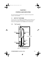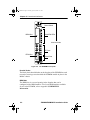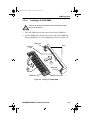
1
ICH1Book Page 1 Thursday, April 18, 1996 7:21 AM ESXMIM/ESXMIM-F2 ETHERNET SWITCH MODULE INSTALLATION GUIDE ICH1Book Page 2 Thursday, April 18, 1996 7:21 AM NOTICE Cabletron Systems reserves the right to make changes in specifications and other information contained in this document without prior notice. The reader should in all cases consult Cabletron Systems to determine whether any such changes have been made. The hardware, firmware, or software described in this manual is subject to change without notice. IN NO EVENT SHALL CABLETRON SYSTEMS BE LIABLE FOR ANY INCIDENTAL, INDIRECT, SPECIAL, OR CONSEQUENTIAL DAMAGES WHATSOEVER (INCLUDING BUT NOT LIMITED TO LOST PROFITS) ARISING OUT OF OR RELATED TO THIS MANUAL OR THE INFORMATION CONTAINED IN IT, EVEN IF CABLETRON SYSTEMS HAS BEEN ADVISED OF, KNOWN, OR SHOULD HAVE KNOWN, THE POSSIBILITY OF SUCH DAMAGES. Copyright 2000 by Cabletron Systems, Inc., P.O. Box 5005, Rochester, NH 03866-5005 All Rights Reserved Printed in the United States of America Order Number: 9031098-03 February 2000 ESXMIM, ESXMIM-F2, SPECTRUM, LANVIEW, SPECTRUM Element Manager, MicroMMAC, MMAC, Flexible Network Bus,and BRIM are registered trademarks and Element Manager, EPIM, APIM, and FPIM are trademarks of Cabletron Systems, Inc. All other product names mentioned in this manual may be trademarks or registered trademarks of their respective companies. FCC NOTICE This device complies with Part 15 of the FCC rules. Operation is subject to the following two conditions: (1) this device may not cause harmful interference, and (2) this device must accept any interference received, including interference that may cause undesired operation. NOTE: This equipment has been tested and found to comply with the limits for a Class A digital device, pursuant to Part 15 of the FCC rules. These limits are designed to provide reasonable protection against harmful interference when the equipment is operated in a commercial environment. This equipment uses, generates, and can radiate radio frequency energy and if not installed in accordance with the operator’s manual, may cause harmful interference to radio communications. Operation of this equipment in a residential area is likely to cause interference in which case the user will be required to correct the interference at his own expense. WARNING: Changes or modifications made to this device which are not expressly approved by the party responsible for compliance could void the user’s authority to operate the equipment. Printed on Recycled Paper ESXMIM/ESXMIM-F2 Installation Guide i ICH1Book Page ii Thursday, April 18, 1996 7:21 AM Notice DOC NOTICE This digital apparatus does not exceed the Class A limits for radio noise emissions from digital apparatus set out in the Radio Interference Regulations of the Canadian Department of Communications. Le présent appareil numérique n’émet pas de bruits radioélectriques dépassant les limites applicables aux appareils numériques de la class A prescrites dans le Règlement sur le brouillage radioélectrique édicté par le ministère des Communications du Canada. VCCI NOTICE This equipment is in the 1st Class Category (information equipment to be used in commercial and/or industrial areas) and conforms to the standards set by the Voluntary Control Council for Interference by Information Technology Equipment (VCCI) aimed at preventing radio interference in commercial and/or industrial areas. Consequently, when used in a residential area or in an adjacent area thereto, radio interference may be caused to radios and TV receivers, etc. Read the instructions for correct handling. CABLETRON SYSTEMS, INC. PROGRAM LICENSE AGREEMENT IMPORTANT: Before utilizing this product, carefully read this License Agreement. This document is an agreement between you, the end user, and Cabletron Systems, Inc. (“Cabletron”) that sets forth your rights and obligations with respect to the Cabletron software program (the “Program”) contained in this package. The Program may be contained in firmware, chips or other media. BY UTILIZING THE ENCLOSED PRODUCT, YOU ARE AGREEING TO BECOME BOUND BY THE TERMS OF THIS AGREEMENT, WHICH INCLUDES THE LICENSE AND THE LIMITATION OF WARRANTY AND DISCLAIMER OF LIABILITY. IF YOU DO NOT AGREE TO THE TERMS OF THIS AGREEMENT, PROMPTLY RETURN THE UNUSED PRODUCT TO THE PLACE OF PURCHASE FOR A FULL REFUND. ii ESXMIM/ESXMIM-F2 Installation Guide ICH1Book Page iii Thursday, April 18, 1996 7:21 AM Notice CABLETRON SOFTWARE PROGRAM LICENSE 1. LICENSE. You have the right to use only the one (1) copy of the Program provided in this package subject to the terms and conditions of this License Agreement. You may not copy, reproduce or transmit any part of the Program except as permitted by the Copyright Act of the United States or as authorized in writing by Cabletron. 2. OTHER RESTRICTIONS. You may not reverse engineer, decompile, or disassemble the Program. 3. APPLICABLE LAW. This License Agreement shall be interpreted and governed under the laws and in the state and federal courts of New Hampshire. You accept the personal jurisdiction and venue of the New Hampshire courts. EXCLUSION OF WARRANTY AND DISCLAIMER OF LIABILITY 1. EXCLUSION OF WARRANTY. Except as may be specifically provided by Cabletron in writing, Cabletron makes no warranty, expressed or implied, concerning the Program (including its documentation and media). CABLETRON DISCLAIMS ALL WARRANTIES, OTHER THAN THOSE SUPPLIED TO YOU BY CABLETRON IN WRITING, EITHER EXPRESSED OR IMPLIED, INCLUDING BUT NOT LIMITED TO IMPLIED WARRANTIES OF MERCHANTABILITY AND FITNESS FOR A PARTICULAR PURPOSE, WITH RESPECT TO THE PROGRAM, THE ACCOMPANYING WRITTEN MATERIALS, AND ANY ACCOMPANYING HARDWARE. 2. NO LIABILITY FOR CONSEQUENTIAL DAMAGES. IN NO EVENT SHALL CABLETRON OR ITS SUPPLIERS BE LIABLE FOR ANY DAMAGES WHATSOEVER (INCLUDING, WITHOUT LIMITATION, DAMAGES FOR LOSS OF BUSINESS, PROFITS, BUSINESS INTERRUPTION, LOSS OF BUSINESS INFORMATION, SPECIAL, INCIDENTAL, CONSEQUENTIAL, OR RELIANCE DAMAGES, OR OTHER LOSS) ARISING OUT OF THE USE OR INABILITY TO USE THIS CABLETRON PRODUCT, EVEN IF CABLETRON HAS BEEN ADVISED OF THE POSSIBILITY OF SUCH DAMAGES. BECAUSE SOME STATES DO NOT ALLOW THE EXCLUSION OR LIMITATION OF LIABILITY FOR CONSEQUENTIAL OR INCIDENTAL DAMAGES, OR ON THE DURATION OR LIMITATION OF IMPLIED WARRANTIES, IN SOME INSTANCES THE ABOVE LIMITATIONS AND EXCLUSIONS MAY NOT APPLY TO YOU. UNITED STATES GOVERNMENT RESTRICTED RIGHTS The enclosed product (a) was developed solely at private expense; (b) contains “restricted computer software” submitted with restricted rights in accordance with Section 52227-19 (a) through (d) of the Commercial Computer Software - Restricted Rights Clause and its successors, and (c) in all respects is proprietary data belonging to Cabletron and/or its suppliers. For Department of Defense units, the product is licensed with “Restricted Rights” as defined in the DoD Supplement to the Federal Acquisition Regulations, Section 52.227-7013 (c) (1) (ii) and its successors, and use, duplication, disclosure by the Government is subject to restrictions as set forth in subparagraph (c) (1) (ii) of the Rights in Technical Data and Computer Software clause at 252.227-7013. Cabletron Systems, Inc., 35 Industrial Way, Rochester, New Hampshire 03867-0505. ESXMIM/ESXMIM-F2 Installation Guide iii Notice DECLARATION OF CONFORMITY Application of Council Directive(s): Manufacturer’s Name: Manufacturer’s Address: European Representative Name: European Representative Address: Conformance to Directive(s)/Product Standards: Equipment Type/Environment: 89/336/EEC 73/23/EEC Cabletron Systems, Inc. 35 Industrial Way PO Box 5005 Rochester, NH 03867 Mr. J. Solari Cabletron Systems Limited Nexus House, Newbury Business Park London Road, Newbury Berkshire RG14 2PZ, England EC Directive 89/336/EEC EC Directive 73/23/EEC EN 55022 EN 50082-1 EN 60950 Networking Equipment, for use in a Commercial or Light Industrial Environment. We the undersigned, hereby declare that the equipment packaged with this notice conforms to the above directives. Manufacturer Legal Representative in Europe Mr. Richard Michaud ___________________________________ Mr. J. Solari ___________________________________ Full Name Full Name Manager of Engineering Services ___________________________________ Title Managing Director - E.M.E.A. ___________________________________ Rochester, NH, USA ___________________________________ Location Newbury, Berkshire, England ___________________________________ iv Title Location ESXMIM/ESXMIM-F2 Installation Guide ICH1Book Page v Thursday, April 18, 1996 7:21 AM CONTENTS CHAPTER 1 INTRODUCTION 1.1 How to Use This Manual ............................................................. 1-1 1.2 ESXMIM Overview ...................................................................... 1-2 1.3 Document Conventions ............................................................... 1-3 1.3.1 Warnings and Notifications ............................................. 1-3 1.3.2 Document Format ........................................................... 1-3 1.4 Related Documents ..................................................................... 1-4 1.5 Getting Help................................................................................. 1-4 CHAPTER 2 CONTROLS AND INDICATORS 2.1 Parts of the ESXMIM ................................................................... 2-1 2.1.1 The Faceplate ................................................................. 2-1 2.1.2 Internal Components ...................................................... 2-4 2.1.3 LANVIEW LEDs .............................................................. 2-6 CHAPTER 3 INSTALLATION 3.1 Unpacking the ESXMIM .............................................................. 3-1 3.2 Setting Mode Switches ................................................................ 3-3 3.3 Pre-Installation Test..................................................................... 3-6 3.4 Installation ................................................................................... 3-8 3.5 Connecting to the Network ........................................................ 3-11 3.5.1 Connecting a 10BASE-T Segment to the ESXMIM ...... 3-12 3.5.2 Connecting a 10BASE-F Segment to the ESXMIM-F2. 3-14 3.5.3 Connecting a 10BASE-T Segment to an EPIM-T ......... 3-16 3.5.4 Connecting a 10BASE-F Segment to an EPIM-F2 or EPIM-F3........................................................................3-19 3.5.5 Connecting a 10BASE-F Segment to an EPIM-F1 ....... 3-21 3.5.6 Connecting an AUI Segment to an EPIM-X or EPIM-A 3-23 3.5.7 Connecting a 10BASE2 Segment to an EPIM-C .......... 3-24 3.6 Backplane Test.......................................................................... 3-26 CHAPTER 4 TROUBLESHOOTING 4.1 Using LANView LEDs.................................................................. 4-1 4.2 Troubleshooting Checklist ........................................................... 4-3 4.3 Using The Reset Switch .............................................................. 4-5 ESXMIM/ESXMIM-F2 Installation Guide v ICH1Book Page vi Thursday, April 18, 1996 7:21 AM Contents APPENDIX A SPECIFICATIONS A.1 Physical Properties ..................................................................... A-1 A.2 Operating Properties ................................................................... A-1 A.3 Environmental Requirements...................................................... A-2 A.4 Certification ................................................................................. A-2 A.5 COM Port Pinout ......................................................................... A-2 APPENDIX B BRIM/EPIM INFORMATION B.1 ESXMIM-Capable BRIMs ........................................................... B-1 B.2 ESXMIM-Capable EPIMs............................................................ B-3 APPENDIX C UPGRADING THE ESXMIM C.1 Locating BRIM Connectors ......................................................... C-1 C.2 Adding EPIMs ............................................................................. C-2 C.3 SIMM Upgrades .......................................................................... C-3 C.3.1 Locating SIMMs .............................................................. C-3 C.3.2 Installing SIMMs ............................................................. C-4 C.3.2.1 Installing a FLASH SIMM............................... C-5 C.3.2.2 Installing an SDRAM or LDRAM SIMM.......... C-6 APPENDIX D ETHERNET CABLING REQUIREMENTS D.1 Network Requirements ............................................................... D-1 D.1.1 10BASE-T Twisted Pair Network.................................... D-1 D.1.2 Multimode Fiber Optic Network ...................................... D-3 D.1.3 Single Mode Fiber Optic Network ................................... D-4 D.1.4 10BASE2 Coaxial Cable Network................................... D-5 D.1.5 Transceiver Requirements.............................................. D-5 INDEX vi ESXMIM/ESXMIM-F2 Installation Guide ICH1Book Page 1 Thursday, April 18, 1996 7:21 AM CHAPTER 1 INTRODUCTION Welcome to the Cabletron Systems ESXMIM/ESXMIM-F2 Ethernet Switch Module Installation Guide. This manual provides installation instructions and reference information for the ESXMIM and ESXMIM-F2 Ethernet Switching Media Interface Modules. NOTE 1.1 This manual covers both the ESXMIM and the ESXMIM-F2. The name ESXMIM will be used to refer to both of the modules unless it is necessary to describe features that are unique to a specific module. HOW TO USE THIS MANUAL To gain a full understanding of this device and its capabilities, and to help eliminate any potential problems during or after installation, please be sure to read and understand all of the instructions/information in this document and in the release notes supplied with your ESXMIM. You should have a general working knowledge of Ethernet or IEEE 802.3 type data networks prior to installing the ESXMIM. The following summarizes the organization of this manual. Chapter 1, Introduction, discusses the use and conventions of the ESXMIM/ESXMIM-F2 Ethernet Switch Module Installation Guide, details the procedures to follow for obtaining assistance from Cabletron Systems, and provides a list of related documentation. Chapter 2, Controls and Indicators, identifies and describes the components and monitoring indicators that make up the ESXMIM. This chapter contains information that is essential to the understanding of the procedures in the rest of this manual. Chapter 3, Installation, details the procedures to follow when unpacking, testing, and installing the ESXMIM. The chapter contains information and step-by-step instructions for connecting network cabling to the ESXMIM and closes with a procedure which may be used to test the operation of the ESXMIM in the network. ESXMIM/ESXMIM-F2 Installation Guide 1-1 ICH1Book Page 2 Thursday, April 18, 1996 7:21 AM Chapter 1: Introduction Chapter 4, Troubleshooting, describes how to use LANVIEW LEDs on the ESXMIM. The chapter defines the different LED conditions and provides a table of simple troubleshooting instructions for module-related difficulties. Appendix A, Specifications, provides the physical specifications and operating requirements of the ESXMIM. This appendix also contains serial port pinout tables for constructing Local Management cables. Appendix B, BRIM/EPIM Information, describes two series of modules called BRIMs and EPIMs, which may be added to the ESXMIM to provide additional capabilities or connectivity options. Appendix C, Upgrading the ESXMIM, details the procedures that must be followed when expanding the capabilities of the ESXMIM. This appendix contains information on memory upgrades and the addition of EPIM modules to the ESXMIM. Appendix D, Ethernet Cabling Requirements, describes the test characteristics that Ethernet cables must adhere to in order to be standards-compliant. Any Ethernet link or cable that is to be connected to the ESXMIM should be verified to be within the specifications and limitations provided in this appendix. 1.2 ESXMIM OVERVIEW The ESXMIM and ESXMIM-F2 are multi-interface Ethernet switching modules designed to provide maximum throughput while supplying comprehensive network management functionality. The ESXMIM and ESXMIM-F2 must be configured in a Cabletron Systems Multi Media Access Center (MMAC) hub. 1-2 ESXMIM/ESXMIM-F2 Installation Guide ICH1Book Page 3 Thursday, April 18, 1996 7:21 AM Document Conventions 1.3 DOCUMENT CONVENTIONS The following are conventions used within this document. 1.3.1 NOTE Warnings and Notifications Note symbol. Calls the reader’s attention to any item of information that may be of special importance. Tip symbol. Conveys helpful hints concerning procedures or actions. TIP ! Caution symbol. Contains information essential to avoid damage to the equipment. CAUT ION Warning symbol. Warns against an action that could result in equipment damage, personal injury or death. 1.3.2 Document Format Figures throughout the document are identified by chapter and illustration number. Many figures contain small numbers at the lower right-hand corner of the illustration. These are Cabletron Systems document control numbers and are not essential to understanding of the document. References to chapters or sections within this document will be printed in boldface type. References to other publications or documents will be printed in italic type. ESXMIM/ESXMIM-F2 Installation Guide 1-3 ICH1Book Page 4 Thursday, April 18, 1996 7:21 AM Chapter 1: Introduction 1.4 RELATED DOCUMENTS Use the following manuals to supplement the procedures and other technical data provided in this manual. This manual references procedures in these manuals, where appropriate, but does not repeat them. Cabletron Systems MMAC Overview and Setup Guide Cabletron Systems Bridge/Router Interface Module Guide(s) Cabletron Systems ESXMIM/ESXMIM-F2 Local Management Guide Cabletron Systems SPECTRUM Element Manager User’s Guide 1.5 GETTING HELP If you need additional support related to the ESXMIM, or if you have any questions, comments, or suggestions concerning this manual, contact Cabletron Systems Technical Support: By phone By CompuServe By Internet mail By FTP Login Password 1-4 (603) 332-9400 Monday – Friday; 8 A.M. – 8 P.M. Eastern Time GO CTRON from any ! prompt [email protected] ctron.com (134.141.197.25) anonymous your email address ESXMIM/ESXMIM-F2 Installation Guide ICH1Book Page 5 Thursday, April 18, 1996 7:21 AM Getting Help Before calling Cabletron Systems Technical Support, have the following information ready: • A description of the failure • A description of any action(s) already taken to resolve the problem (e.g., changing mode switches, rebooting the unit, etc.) • A description of your network environment (layout, cable type, etc.) • Network load and frame size at the time of trouble (if known) • The serial and revision numbers of all Cabletron Systems products in the ESXMIM network • The device history (i.e., have you returned the device before, is this a recurring problem, etc.) • Any previous Return Material Authorization (RMA) numbers ESXMIM/ESXMIM-F2 Installation Guide 1-5 ICH1Book Page 6 Thursday, April 18, 1996 7:21 AM Chapter 1: Introduction 1-6 ESXMIM/ESXMIM-F2 Installation Guide ICH1Book Page 1 Thursday, April 18, 1996 7:21 AM CHAPTER 2 CONTROLS AND INDICATORS This chapter identifies and describes the components and operational indicators of the ESXMIM. 2.1 PARTS OF THE ESXMIM In some instances, the ESXMIM and ESXMIM-F2 provide different front panel connectivity options, LED indicators, or other labeling. In these instances, the configuration of the ESXMIM will be discussed first. 2.1.1 The Faceplate Reset Switch BRIM Slot LANVIEW LEDs Knurled Knobs RJ45 Ports EPIM Slot Serial Ports 01 Figure 2-1 The ESXMIM Faceplate ESXMIM/ESXMIM-F2 Installation Guide 2-1 ICH1Book Page 2 Thursday, April 18, 1996 7:21 AM Chapter 2: Controls and Indicators Reset Switch BRIM Slot LANVIEW LEDs Knurled Knobs ST Ports EPIM Slot Serial Ports 02 Figure 2-2 The ESXMIM-F2 Faceplate Knurled Knobs The black plastic knurled knobs on the faceplate of the ESXMIM are used to turn the securing screws that hold the ESXMIM module in place in the MMAC chassis. BRIM Slot The BRIM slot is a covered opening in the faceplate that can be configured with a BRIM module. For a list of BRIM modules available for use in the ESXMIM, refer to Appendix B, BRIM/EPIM Information. 2-2 ESXMIM/ESXMIM-F2 Installation Guide ICH1Book Page 3 Thursday, April 18, 1996 7:21 AM Parts of the ESXMIM EPIM Slot The EPIM slot is a covered opening in the ESXMIM faceplate that can be configured with an optional EPIM module. For a list of EPIM modules which may be used in the ESXMIM, refer to Appendix B, BRIM/EPIM Information. Reset Button The recessed reset button re-initializes the ESXMIM processor. The activation of this switch will not initialize Non-Volatile Random Access Memory (NVRAM) where the ESXMIM stores configuration and management parameters. The Reset button may be pressed with the point of a pencil or pen. Once pushed in, the ESXMIM will re-initialize itself. LANVIEW LEDs The ESXMIM incorporates the LANVIEW status monitoring and diagnostic system. LANVIEW LEDs can help diagnose many problems, such as a fault in network cabling. LANVIEW LEDs are identified in Section 2.1.3, LANVIEW LEDs. RJ45 Ports The ESXMIM module provides five front panel RJ45 ports for connection to 10BASE-T links. The RJ45 ports of the ESXMIM use the 10BASE-T standard pinouts and signaling. ST Ports The ESXMIM-F2 provides five pairs of front panel ST ports for connection to five 10BASE-F links. The ST ports of the ESXMIM-F2 are 10BASE-F and FOIRL compliant. Serial Ports The ESXMIM faceplate provides two serial communications ports for the connection of out-of-band management devices. ESXMIM/ESXMIM-F2 Installation Guide 2-3 ICH1Book Page 4 Thursday, April 18, 1996 7:21 AM Chapter 2: Controls and Indicators 2.1.2 Internal Components The components listed in the following entries are all hidden inside the MMAC chassis when the ESXMIM has been installed. These components may be located by removing the ESXMIM from the chassis and holding the module in the orientation shown in Figure 2-3 and Figure 2-4. Power and Management Backplane Connection SDRAM SIMM Slot Dip Switch Bank 03 LDRAM SIMM Slot FLASH Memory SIMM Slot Figure 2-3 ESXMIM Internal Components Power and Management Backplane Connection The ESXMIM connects to the power and management backplane bus of the MMAC chassis through this multipin connector. 2-4 ESXMIM/ESXMIM-F2 Installation Guide ICH1Book Page 5 Thursday, April 18, 1996 7:21 AM Parts of the ESXMIM SDRAM SIMM Slot The ESXMIM motherboard provides the option of upgrading memory capacity by using Single In-line Memory Modules (SIMMs). The ESXMIM comes with 4 Megabytes (MB) of Shared Dynamic Random Access Memory (SDRAM). SDRAM holds packets coming onto the module temporarily while forwarding, filtering, and error checking decisions are made. LDRAM SIMM Slot The ESXMIM comes with 4 MB of Local Dynamic Random Access Memory (LDRAM). LDRAM is the “Main” memory from which the switching functionality of the ESXMIM operates. FLASH Memory SIMM Slot The ESXMIM incorporates 2 MB of FLASH Electrically Erasable Programmable Read Only Memory (FLASH EEPROM). FLASH memory holds the operating instruction code of the ESXMIM. When the module is activated, the instruction code (firmware) held in FLASH memory is forwarded to Main memory, decompressed, and used to startup the ESXMIM. The use of FLASH memory, in conjunction with the runtime download capabilities of the ESXMIM, allows for the downloading of firmware to the module without requiring that the module be shut down. The firmware download may be performed at any time during the operation of the module, and the new firmware image will be utilized at the next reset of the module. Dip Switch Bank The ESXMIM provides a bank of eight dual-position, or “dip” switches. Several of these switches are used for testing purposes during the manufacturing process. The dip switches can also be used to clear the NVRAM of the ESXMIM which contains configuration and local management settings, or to force the ESXMIM to request a new firmware image from a properly configured BOOTP server. ESXMIM/ESXMIM-F2 Installation Guide 2-5 ICH1Book Page 6 Thursday, April 18, 1996 7:21 AM Chapter 2: Controls and Indicators Onboard Safety Fuse EPIM Connector Pins 04 Flexible Network Bus Connection Figure 2-4 ESXMIM Internal Components EPIM Connector The EPIM connector is a set of built-in pins that connect the ESXMIM to an optional EPIM module. The proper insertion of the EPIM will automatically connect these pins to the connector located on the EPIM. Onboard Safety Fuse The onboard safety fuse protects the ESXMIM from potentially damaging power spikes or surges. Under normal operation, the safety fuse will not require customer concern. Flexible Network Bus Connection This multipin connector allows the ESXMIM to connect to Ethernet Channel A of the MMAC Flexible Network Bus backplane. 2.1.3 LANVIEW LEDs The LANVIEW LEDs on the ESXMIM faceplate provide diagnostic and status monitoring information. The LEDs are identified by labels which border the LED in question. 2-6 ESXMIM/ESXMIM-F2 Installation Guide ICH1Book Page 7 Thursday, April 18, 1996 7:21 AM Parts of the ESXMIM ESXMIM Figure 2-5 ESXMIM-F2 ESXMIM LANVIEW LEDs The use of these LEDs for troubleshooting is covered in Chapter 4, Troubleshooting. The following LEDs are on the faceplate of the ESXMIM: CPU The CPU LED indicates the operating status of the ESXMIM, and is primarily concerned with the operation of the onboard twin i960 RISC processors. RJ45 The RJ45 LED of the ESXMIM indicates that interface number one of the ESXMIM module has been assigned to the front panel RJ45 port #1. FIBER The FIBER LED of the ESXMIM-F2 indicates that interface number one of the ESXMIM-F2 module has been assigned to the front panel ST port pair #1. ESXMIM/ESXMIM-F2 Installation Guide 2-7 ICH1Book Page 8 Thursday, April 18, 1996 7:21 AM Chapter 2: Controls and Indicators CH A The CH A LED indicates the ESXMIM bridge interface number one has been assigned to the backplane Ethernet Channel A connection. XMIT The XMIT LED indicates the transmit status of the port or interface it is associated with. RCV The RCV LED indicates the reception of Ethernet packets by the port or interface the LED is associated with. 2-8 ESXMIM/ESXMIM-F2 Installation Guide ICH1Book Page 1 Thursday, April 18, 1996 7:21 AM CHAPTER 3 INSTALLATION This chapter contains instructions for the following procedures: • • • • • Preparing the ESXMIM for installation Testing the ESXMIM prior to network connection Installing the ESXMIM into a Multi Media Access Center (MMAC) Connecting the ESXMIM to a network Testing the installed ESXMIM 3.1 UNPACKING THE ESXMIM Unpack the ESXMIM as follows: ! Observe all antistatic precautions when handling sensitive electronic equipment. CAUT ION 1. Remove the shipping material covering the ESXMIM. 2. Verify the contents of the packing carton. The carton, as shipped, should contain the following items: Item Quantity ESXMIM 1 Disk Containing Firmware Images 2 Grounding Strap 1 RJ45 Adapter Kit 1 Release Notes 1 ESXMIM Manuals 2 ESXMIM/ESXMIM-F2 Installation Guide 3-1 ICH1Book Page 2 Thursday, April 18, 1996 7:21 AM Chapter 3: Installation 3. Carefully remove the module from the shipping box. Leave the module in its non-conductive bag until you are ready to install it. 4. Visually inspect the non-conductive bag. If there are any signs of damage, contact Cabletron Systems Technical Support immediately. 5. Place the static grounding strap properly on your wrist before opening the non-conductive bag. 6. Open the non-conductive bag by tearing the black and yellow tape seal. ! Do not cut the bag open, as damage to the ESXMIM may result. CAUT ION 7. Perform a second visual inspection of the module. 3-2 ESXMIM/ESXMIM-F2 Installation Guide ICH1Book Page 3 Thursday, April 18, 1996 7:21 AM Setting Mode Switches 3.2 SETTING MODE SWITCHES A bank of dip switches, located at the bottom of the ESXMIM (Figure 3-1), provide several configuration options. All switches ship in the OFF position. i960 Never adjust switch settings while the ESXMIM is on. Not only is this dangerous, but the change in state (i.e., position) activates the switch function only after reinstalling or cycling power to the board. i960 05 Figure 3-1 O n ON O f f 1 ALCO GDSO8S 2 3 4 5 6 7 8 ESXMIM Dip Switches ESXMIM/ESXMIM-F2 Installation Guide 3-3 ICH1Book Page 4 Thursday, April 18, 1996 7:21 AM Chapter 3: Installation Switch definitions are as follows: • Switch 1: Cabletron Systems use only. • Switch 2: Cabletron Systems use only. • Switch 3: Not Used. • Switch 4: Not Used. • Switch 5: Cabletron Systems use only. • Switch 6: Forced Download. Changing the state of this switch (i.e., moving the switch from one position to another) clears download information from Non-Volatile Random Access Memory (NVRAM) and forces a BOOTP download After changing the position of switch 6 and restarting the ESXMIM, the ESXMIM requests a new image download until it either receives a new image or the reset button on the front panel is pressed. When the reset button is pressed, the ESXMIM continues trying to contact a BOOTP server, but will timeout in approximately one minute. If the ESXMIM times out, the image is loaded from its FLASH memory. NOTE Do NOT change the state of Switch 6 unless you have a station acting as a BOOTP server for the ESXMIM. This BOOTP station must reference a station that is acting as a TFTP server and that contains the ESXMIM image file. The ESXMIM will request the location of the image file from the BOOTP server and use the Trivial File Transfer Protocol (TFTP) to download that file from the TFTP server. If one of these requirements is not met, the ESXMIM Forced Download operation will not be completed correctly. 3-4 ESXMIM/ESXMIM-F2 Installation Guide ICH1Book Page 5 Thursday, April 18, 1996 7:21 AM Setting Mode Switches • Switch 7: NVRAM Reset. The ESXMIM uses NVRAM to store user-entered parameters such as IP addresses, device name, etc. Changing the state of this switch (i.e., moving the switch from one position to another and leaving it there) resets these parameters to the factory defaults. Once the ESXMIM resets, you can either use the defaults or re-enter your own parameters. The ESXMIM stores these parameters in NVRAM when the device powers down. These parameters remain in NVRAM until the switch changes state again. NOTE • Do not change the state of Switch 7 unless you intend to reset the ESXMIM user parameters to the factory default settings. Switch 8: Password Defaults. Changing the state of this switch (i.e., moving the switch from one position to another and leaving it there) clears user-entered passwords stored in NVRAM, and restores default passwords. Once reset you can use the defaults or re-enter your passwords. NOTE Do not change the state of Switch 8 unless you want to reset the ESXMIM user-configured passwords to their factory default settings. ESXMIM/ESXMIM-F2 Installation Guide 3-5 ICH1Book Page 6 Thursday, April 18, 1996 7:21 AM Chapter 3: Installation 3.3 PRE-INSTALLATION TEST Before installing the ESXMIM in a live network, you may want to test the module in a controlled situation to ensure that it is switching packets. You can perform this test with two workstations (see Figure 3-2), using an MMAC with an ESXMIM installed and set up as follows: 1. Install the ESXMIM into an MMAC that is not attached to a network. MMAC3/FNB with ESXMIM ESXMIM Move between Ports MMAC-3FNB Client Workstation 06 File Server Workstation Figure 3-2 Pre-Installation Test Configuration 2. Connect the first workstation to any ESXMIM port (except for port 1). NOTE Port 1 requires a Local Management change to access the ESXMIM front panel (Default = Channel A connection). Refer to the Configuration Screen section of the ESXMIM/ESXMIM-F2 Local Management Guide. 3. Connect the second workstation to any other ESXMIM port (except for port 1). 3-6 ESXMIM/ESXMIM-F2 Installation Guide ICH1Book Page 7 Thursday, April 18, 1996 7:21 AM NOTE Port 6, the EPIM, may require a transceiver or adapter for proper connection. Port 7, the BRIM, requires additional network equipment for proper testing. 4. Designate the first workstation as a file server and the second one as the client (refer to individual workstation manuals for instructions on assigning server/client relationships). 5. Send packets between the two workstations to verify the proper operation of the ESXMIM. If a failure occurs, contact Cabletron Systems Technical Support. ESXMIM/ESXMIM-F2 Installation Guide 3-7 ICH1Book Page 8 Thursday, April 18, 1996 7:21 AM Chapter 3: Installation 3.4 INSTALLATION Installing the ESXMIM into any MMAC hub is an easy operation and requires no special tools. However, when you install your device, keep the following in mind: Any installation operations should be performed only by qualified personnel. ! You may install the ESXMIM in any slot except for slot 1 (farthest slot to the right) of the MMAC chassis. CAUT ION ! Observe all antistatic precautions when handling sensitive electronic equipment. CAUT ION Install the ESXMIM into the MMAC-FNB (backplane) as follows: NOTE We recommend powering down your MMAC when inserting or removing modules, even though Cabletron Systems modules have “hot swap” capabilities. 1. Remove the safety bars that protect the chassis and remove any module to be replaced or blank MMAC slot covers, in accordance with the installation and removal procedures for these items. 2. Holding the ESXMIM by the front panel, or by the edges of the board, align the bottom and top edges of the board with the guides. Make sure that both the bottom and top edges of the card rest in these guides. 3. Slide the ESXMIM (Figure 3-3) into the desired slot of the MMAC card cage. 4. Firmly press the module connections into the backplane. Do not try to force the module into place or use the knurled knobs to draw the module into the backplane. 3-8 ESXMIM/ESXMIM-F2 Installation Guide ICH1Book Page 9 Thursday, April 18, 1996 7:21 AM Installation ! Forcing a misaligned module into place can damage the ESXMIM or the MMAC backplane. CAUT ION Knurled Knob MMAC-M8FNB SN RESET CPU PRT1 RJ45 CH A XMT 1 RCV XMT 2 RCV XMT 3 RCV XMT 4 RCV XMT 5 RCV XMT 6 RCV 1 2 3 4 5 C O M 1 C O M 2 ETHERNET 07 Module Guide Channels Figure 3-3 Installing the ESXMIM 5. Secure the module to the MMAC chassis by tightening the knurled knobs. If you do not tighten the knurled knobs, vibration can cause the module to lose contact with the backplane and disrupt your network. 6. Reinstall the MMAC chassis safety bars. 7. Power-up the MMAC (if it is not already ON). ESXMIM/ESXMIM-F2 Installation Guide 3-9 ICH1Book Page 10 Thursday, April 18, 1996 7:21 AM Chapter 3: Installation 8. Observe the status of the LANVIEW LEDs (Figure 3-4) on the ESXMIM. When the CPU LED is amber, the module is in boot state. During this approximately one minute period the ESXMIM cycles through a series of internal diagnostics. 08 Figure 3-4 ESXMIM LANVIEW LEDs 9. After the system boot procedure, the CPU LED should be flashing green, indicating proper ESXMIM operation. NOTE The ESXMIM defaults to Channel A operation on initial power-up. If there is no Ethernet repeater in the modular hub, the ESXMIM must be configured to utilize the front panel interface 1 port through LM. Proceed to Section 3.5, Connecting to the Network, to connect the appropriate network segments to the ESXMIM and individual EPIMs (for connections to individual BRIMs see the appropriate BRIM Guides). 3-10 ESXMIM/ESXMIM-F2 Installation Guide ICH1Book Page 11 Thursday, April 18, 1996 7:21 AM Connecting to the Network 3.5 CONNECTING TO THE NETWORK This section gives procedures for connecting the ESXMIM and various EPIMs to the network. Refer to the list below and follow the procedures in the subsection for appropriate module type: • Connecting a 10BASE-T Segment to the ESXMIM: Section 3.5.1 • Connecting a 10BASE-F Segment to the ESXMIM-F2: Section 3.5.2 • Connecting a 10BASE-T Segment to an EPIM-T: Section 3.5.3 • Connecting a 10BASE-F Segment to an EPIM-F2 or EPIM-F3: Section 3.5.4 • Connecting a 10BASE-F Segment to an EPIM-F1: Section 3.5.5 • Connecting an AUI Segment to an EPIM-X or EPIM-A: Section 3.5.6 • Connecting a 10BASE2 Segment to an EPIM-C: Section 3.5.7 ESXMIM/ESXMIM-F2 Installation Guide 3-11 ICH1Book Page 12 Thursday, April 18, 1996 7:21 AM Chapter 3: Installation 3.5.1 Connecting a 10BASE-T Segment to the ESXMIM Before connecting a segment to the ESXMIM, check each end of the segment to verify wire crossover. NOTE To establish a link, you must have an odd number of crossovers (preferably one) between 10BASE-T devices of the same type (i.e., from repeater to repeater or switch to switch). To connect a Twisted Pair Segment to the ESXMIM perform the following steps: 1. Align the RJ45 connector with the socket of the RJ45 port. The connector will only insert and lock if the raised locking clip of the RJ45 connector is inserted into the correct location. Figure 3-5 shows the RJ45 ports on the ESXMIM to which 10BASE-T cables may be connected. 09 Figure 3-5 3-12 ESXMIM Twisted Pair Connection ESXMIM/ESXMIM-F2 Installation Guide ICH1Book Page 13 Thursday, April 18, 1996 7:21 AM Connecting to the Network 2. Press the RJ45 connector into the port until the click of the locking clip is felt. The pressure required to perform this should be minimal. If you encounter resistance or excessive friction, remove the connector and check the port for obstruction. Also, verify that the connector and the port are of the same type. Once the locking clip snaps into place, the RJ45 connector will remain in the port. 3. Check for a valid link by examining the RCV LEDs. A solid green LED indicates that a valid link has been achieved. If the LED remains dark, perform each of the following steps until it is lit: a. Check that the 10BASE-T device at the other end of the twisted pair segment is ON. b. Verify that the RJ45 connectors on the 10BASE-T segment have the proper pinouts (Figure 3-8). c. Check the cable for continuity. d. Check that the twisted pair connection meets dB loss and cable specifications outlined in Appendix D, Ethernet Cabling Requirements. If a link still has not been established, contact Cabletron Systems Technical Support. ESXMIM/ESXMIM-F2 Installation Guide 3-13 ICH1Book Page 14 Thursday, April 18, 1996 7:21 AM Chapter 3: Installation 3.5.2 Connecting a 10BASE-F Segment to the ESXMIM-F2 Each fiber optic link consists of two strands of fiber optic cabling: the transmit (TX) and the receive (RX). The transmit strand from a module port connects to the receive port of a fiber optic Ethernet device at the other end of the segment. The receive strand of the applicable port on the module connects to the transmit port of the fiber optic Ethernet device. Cabletron Systems recommends labeling fiber optic cables to indicate receive and transmit ends. Many cables are prelabeled, providing matching labels or tapes at both ends of each strand of cable. 1. Remove the protective plastic covers from the fiber optic ports on the applicable port on the module, and from the ends of the connectors on each fiber strand. ! CAUT ION Do not touch the ends of the fiber optic strands, and do not let the ends come in contact with dust, dirt, or other contaminants. Contamination of cable ends causes problems in data transmissions. If necessary, clean contaminated cable ends using isopropyl alcohol and a soft, clean, lint-free cloth. 2. Attach one fiber to the applicable receive port on the module. Insert the ST connector into the port with the alignment slot on the connector inserted over the locking key on the port. Turn the connector clockwise to lock it down. 3-14 ESXMIM/ESXMIM-F2 Installation Guide ICH1Book Page 15 Thursday, April 18, 1996 7:21 AM Connecting to the Network 10 Figure 3-6 ST Connector Insertion 3. Attach the second fiber of the pair to the associated transmit port on the module. Use the same procedure for insertion of the ST connector. 4. At the other end of the fiber optic cable, attach the fiber pair to the transmit and receive ports of the device. Check that the LNK LED for the applicable ESXMIM-F2 port is on. If the LED is not ON, that port does not have a valid link. Perform each of the following steps until you reach a resolution of the problem and achieve a link. • Check that the device at the other end of the link is ON. • Verify proper cross-over of the fiber strands. Try swapping the transmit and receive connections at only one end of the link. ESXMIM/ESXMIM-F2 Installation Guide 3-15 ICH1Book Page 16 Thursday, April 18, 1996 7:21 AM Chapter 3: Installation • Verify that the fiber connection meets the dB loss specifications outlined in Appendix D, Ethernet Cabling Requirements. If you are still unable to establish a link, attempt to make the connection between the devices with another fiber optic cable. If this is unsuccessful, contact Cabletron Systems Technical Support. 3.5.3 NOTE Connecting a 10BASE-T Segment to an EPIM-T For proper operation, the EPIM-T module to be configured for use in the ESXMIM module must be of EPIM board revision 04 or greater. Board revision numbers are found following the part number printed on the Printed Circuit Board of the EPIM. Before connecting a segment to the EPIM-T, check each end of the segment to determine wire crossover. If the wires do not cross over, use the switch on the EPIM-T to internally cross over the RJ45 port. Refer to Figure 3-7 to properly set the EPIM-T crossover switch. NOTE 3-16 To establish a link, you must have an odd number of crossovers (preferably one) between 10BASE-T devices of the same type (i.e., from repeater to repeater or transceiver to transceiver). ESXMIM/ESXMIM-F2 Installation Guide ICH1Book Page 17 Thursday, April 18, 1996 7:21 AM Connecting to the Network Position X (crossed over) 1. RX+ 2. RX3. TX+ 4. NC 5. NC 6. TX7. NC 8. NC 11 Position = (not crossed over) 1. TX+ 2. TX3. RX+ 4. NC Figure 3-7 5. NC 6. RX7. NC 8. NC EPIM-T Crossover Switch 1. Align the RJ45 connector with the socket of the RJ45 port. The connector will only insert and lock if the raised locking clip of the RJ45 connector is inserted into the correct location. 2. Press the RJ45 connector into the port until the click of the locking clip is felt. The pressure required to perform this should be minimal. If you encounter resistance or excessive friction, remove the connector and check the port for obstruction. Also, verify that the connector and the port are of the same type. Once the locking clip snaps into place, the RJ45 connector will remain in the port. ESXMIM/ESXMIM-F2 Installation Guide 3-17 ICH1Book Page 18 Thursday, April 18, 1996 7:21 AM Chapter 3: Installation 3. Check that the LNK indicator LED is ON. If the indicator is not ON, the port does not have a valid link. Perform each of the following steps until you reach a resolution of the problem and achieve a link. a. Check that the 10BASE-T device at the other end of the twisted pair segment is ON. b. Verify that the RJ45 connectors on the twisted pair segment have the proper pinouts. ESXMIM RJ45 Port 10BASE-T Device Port Straight-Through 1 Tx+ 2 Tx- Rx+ 1 Rx- 2 3 Rx- Tx- 3 Tx+ 6 6 Rx+ RX+/RX- and TX+/TX- must share a common color pair Figure 3-8 12 Cable Pinouts - RJ45 Port c. Check the cable for continuity. d. Check that the twisted pair connection meets dB loss and cable specifications outlined in Appendix D, Ethernet Cabling Requirements. 4. If you still cannot establish a link, contact Cabletron Systems Technical Support. To remove the RJ45 connector from the port once it is locked in, grasp the cable where it enters the network device. Using your finger or a non-conductive probe (the cap of a ballpoint pen is a useful tool for recessed ports) pinch the exposed arm of the locking clip towards the main body of the housing. When the arm contacts the housing, the locking clip has been disengaged. Without releasing the arm, gently pull the RJ45 connector directly out of the port. 3-18 ESXMIM/ESXMIM-F2 Installation Guide ICH1Book Page 19 Thursday, April 18, 1996 7:21 AM Connecting to the Network If the connector will not come out, there may be damage to the locking clip. Examine the arm of the locking clip. While pressing the arm back toward the shell of the connector, verify that the clip, located within the port, is being moved. If the clip is broken, you may need to use a non-conductive probe to disengage the locking clip. Do not place foreign objects into device ports while they are connected to a power source. 3.5.4 NOTE Connecting a 10BASE-F Segment to an EPIM-F2 or EPIM-F3 For proper operation, the EPIM-F2 module to be configured for use in the ESXMIM module must be of EPIM board revision 05 or greater. EPIM-F3 modules used in the ESXMIM must be of EPIM board revision 02 or greater. Board revision numbers are found following the part number printed on the Printed Circuit Board of the EPIM. Each fiber optic link consists of two strands of fiber optic cabling: the transmit (TX) and the receive (RX). The transmit strand from a module port connects to the receive port of a fiber optic Ethernet device at the other end of the segment. The receive strand of the applicable port on the module connects to the transmit port of the fiber optic Ethernet device. Cabletron Systems recommends labeling fiber optic cables to indicate receive and transmit ends. Many cables are prelabeled, providing matching labels or tapes at both ends of each strand of cable. 1. Remove the protective plastic covers from the fiber optic ports on the applicable port on the module, and from the ends of the connectors on each fiber strand. ! CAUT ION Do not touch the ends of the fiber optic strands, and do not let the ends come in contact with dust, dirt, or other contaminants. Contamination of cable ends causes problems in data transmissions. If necessary, clean contaminated cable ends using alcohol and a soft, clean, lint-free cloth. ESXMIM/ESXMIM-F2 Installation Guide 3-19 ICH1Book Page 20 Thursday, April 18, 1996 7:21 AM Chapter 3: Installation 2. Attach one fiber to the applicable receive port on the module. Insert the ST connector into the port with the alignment slot on the connector inserted over the locking key on the port. Turn the connector clockwise to lock it down. 13 Figure 3-9 ST Connector Insertion 3. Attach the other fiber of the pair to the applicable transmit port on the module. Use the same procedure for insertion of the ST connector. 4. At the other end of the fiber optic cable, attach the fiber pair to the transmit and receive ports of the device. If link indicators are present for the fiber optic connection, check that they are ON. If an indicator is present but not ON, that port does not have a valid link. Perform each of the following steps until you reach a resolution of the problem and achieve a link. • Check that the device at the other end of the link is ON. • Verify proper cross-over of the fiber strands. Try swapping the transmit and receive connections at only one end of the link. • Verify that the fiber connection meets the dB loss specifications outlined in Appendix D, Ethernet Cabling Requirements. If you are still unable to establish a link, attempt to make the connection between the devices with another fiber optic cable. If this is unsuccessful, contact Cabletron Systems Technical Support. 3-20 ESXMIM/ESXMIM-F2 Installation Guide ICH1Book Page 21 Thursday, April 18, 1996 7:21 AM Connecting to the Network 3.5.5 NOTE ! CAUT ION Connecting a 10BASE-F Segment to an EPIM-F1 For proper operation, the EPIM-F1 module to be configured for use in the ESXMIM module must be of EPIM board revision 05 or greater. Board revision numbers are found following the part number printed on the Printed Circuit Board of the EPIM. When connecting a fiber optic link segment with SMA 906 connectors to an EPIM-F1 with SMA ports, make sure each connector uses half alignment, NOT full alignment, sleeves. A full alignment sleeve damages the receive port. SMA 905 connectors do not need alignment sleeves. Each fiber optic link consists of two strands of fiber optic cabling: the transmit (TX) and the receive (RX). The transmit strand from a module port connects to the receive port of a fiber optic Ethernet device at the other end of the segment. The receive strand of the applicable port on the module connects to the transmit port of the fiber optic Ethernet device. Cabletron Systems recommends labeling fiber optic cables to indicate receive and transmit ends. Many cables are prelabeled, providing matching labels or tapes at both ends of each strand of cable. 1. Remove the protective plastic covers from the fiber optic ports on the applicable port on the module, and from the ends of the connectors on each fiber strand. ! CAUT ION Do not touch the ends of the fiber optic strands, and do not let the ends come in contact with dust, dirt, or other contaminants. Contamination of cable ends causes problems in data transmissions. If necessary, clean contaminated cable ends using alcohol and a soft, clean, lint-free cloth. 2. Attach one fiber to the receive port (RX) on the EPIM-F1. Insert the SMA connector into the port. Turn the connector clockwise until the connector will no longer turn easily. Do not overtighten the connector. ESXMIM/ESXMIM-F2 Installation Guide 3-21 ICH1Book Page 22 Thursday, April 18, 1996 7:21 AM Chapter 3: Installation 14 Figure 3-10 SMA Connector Insertion 3. Attach the other fiber of the pair to the applicable transmit port on the module. 4. At the other end of the fiber optic cable, attach the fiber pair to the transmit and receive ports of the device. If link indicators are present for the fiber optic connection, check that they are ON. If an indicator is present but not ON, that port does not have a valid link. Perform each of the following steps until you reach a resolution of the problem and achieve a link. • Check that the device at the other end of the link is ON. • Verify proper cross-over of the fiber strands. Try swapping the transmit and receive connections at only one end of the link. • Verify that the fiber connection meets the dB loss specifications outlined in Appendix D, Ethernet Cabling Requirements. If you are still unable to establish a link, attempt to make the connection between the devices with another fiber optic cable. If this is unsuccessful, contact Cabletron Systems Technical Support. 3-22 ESXMIM/ESXMIM-F2 Installation Guide ICH1Book Page 23 Thursday, April 18, 1996 7:21 AM Connecting to the Network 3.5.6 NOTE Connecting an AUI Segment to an EPIM-X or EPIM-A Ensure that the external transceiver to which the EPIM-A connects does not have the signal quality error (SQE or “heartbeat”) test function enabled. The EPIM does not operate if the transceiver has the SQE test function enabled. Refer to the applicable transceiver manual for additional information. Attach an external transceiver to the network segment intended for AUI port connection. For additional information, refer to the applicable transceiver manual. Attach an AUI cable, no longer than 50 meters in length, to the external transceiver. 1. Align the DB15 connector of the AUI cable with the AUI port of the EPIM as shown in Figure 3-11. The port will only connect if it is properly aligned. 2. Firmly press the AUI connector over the AUI port. If there is a slide latch present for the AUI connector, slide it over the locking posts on the DB15 port. 15 Figure 3-11 AUI Connector Insertion ESXMIM/ESXMIM-F2 Installation Guide 3-23 ICH1Book Page 24 Thursday, April 18, 1996 7:21 AM Chapter 3: Installation 3. If the transceiver PWR LED is OFF with the AUI cable connected: a. check the AUI connections for proper pinouts, b. check the cable for continuity, c. reconnect the AUI cable to the ESXMIM and the device. If the transceiver PWR LED remains OFF, contact Cabletron Systems. 3.5.7 NOTE Connecting a 10BASE2 Segment to an EPIM-C For proper operation, the EPIM-C module to be configured for use in the ESXMIM module must be of EPIM board revision 05 or greater. Board revision numbers are found following the part number printed on the Printed Circuit Board of the EPIM. To connect a thin coaxial cable segment to an EPIM-C perform the following steps: Before attaching a male BNC connector to a female BNC barrel connector or terminator, look into the end of the connector to verify that the gold contact pin is present and centered. Any bent or broken pins may not connect properly and should be replaced. 1. Set the Internal Termination (TERM) switch, located to the right of the port and labeled TERM, to a. ON position ( ) to internally terminate the thin coaxial cable segment at the port. Thin coaxial cable segments may be directly connected to the port. b. OFF position ( ) to not internally terminate the thin coaxial cable segment at the port. Segments may only be connected through T-connectors which are connected to properly terminated segments on both ends. NOTE 3-24 Failure to terminate each T-connector segment may result in improper segment operation. Place a terminator on any open female connection on the T-connector. ESXMIM/ESXMIM-F2 Installation Guide ICH1Book Page 25 Thursday, April 18, 1996 7:21 AM Connecting to the Network c. Attach a terminated thin coaxial cable segment or a terminator to the other female connector on the T-connector. 2. Align the guide channels of the BNC (male) metal housing with the locking keys of the BNC barrel (female) connector on the EPIM. Slide the metal housing of the male connector straight over the metal housing of the female connector. 3. Once the housing stops moving in, turn the metal housing clockwise while continuing to apply light forward pressure. 16 Figure 3-12 BNC Connector Insertion 4. The locking keys of the female connector will pull the connector in until they reach the circular locking holes at the end of the guide channels. The keys will click the connector into place and hold it there. To remove the BNC connector, perform the steps above in reverse order, turning the metal housing counter-clockwise and pulling the connector straight off of the female BNC connector. ESXMIM/ESXMIM-F2 Installation Guide 3-25 ICH1Book Page 26 Thursday, April 18, 1996 7:21 AM Chapter 3: Installation 3.6 BACKPLANE TEST If you plan to utilize the ESXMIM Channel A connection (default), you may want to verify that packets can pass over the network backplane through the ESXMIM. Again, you can use two workstations set up as file server and client. See Figure 3-13. 1. After the ESXMIM is installed in the MMAC, connect the client workstation to any ESXMIM port (except for port 1). 2. Connect the server workstation to another Ethernet MIM that is accessible from Channel A (i.e., a RIC MIM, if controlled by an EMME or EMM-E6, a MIM that resides on Channel A in a hub controlled by an IRM, or any Ethernet MIM in a hub controlled by an EMME or EMM-E6, including the management modules). 3. Send packets between the two workstations to verify the proper operation of the ESXMIM. A “ping” test will send packets from one station to another. If a failure occurs, contact Cabletron Systems Technical Support. ESXMIM TPRMIM-33 CXRMIM CXRMIM TPMIM-24 EMM-E6 TPMIM-24 XMT RCV 2 XMT RCV 3 XMT RCV 4 XMT RCV 5 XMT RCV 6 BRIM-FD2 EPIM-A PWR LNK 1 TWR WRP E SYNC 2 PWR BRIM-W2 1 EPIM-A TWR WRP XMT RCV LNK RJ45 CH A XMT RCV XMT RCV BRIM-FD2 SN 3 6 5 T1/FT1 C O M 1 TST RED SYN CTS TST LNK YEL STB DSR LNK EPIM-A PWR 4 C O M 2 F Client Workstation 17 File Server Workstation Figure 3-13 3-26 Backplane Test Configuration ESXMIM/ESXMIM-F2 Installation Guide ICH1Book Page 1 Thursday, April 18, 1996 7:21 AM CHAPTER 4 TROUBLESHOOTING This chapter provides diagnostic and troubleshooting information. 4.1 USING LANVIEW LEDS The ESXMIM uses the Cabletron Systems built-in visual diagnostic and status monitoring system called LANVIEW. With LANVIEW, you can quickly scan the ESXMIM LEDs to observe network status or diagnose network problems. Table 4-1 LED LANVIEW LED Messages Color Description Green (Flashing) Normal operation Amber Startup operations PRT 1: RJ45, FIBER, or CH A Green If the LED is not lit, the ESXMIM may not be receiving power. See the Troubleshooting Checklist. CPU error condition Press the reset switch on the ESXMIM front panel to re-initialize the board. This may clear the error. If the board does not re-initialize, it has probably failed. Call Cabletron Systems Technical Support. Indicates connection status of interface 1 Port 1 defaults to Channel A. If this LED remains off after setting Port 1 to access the faceplate RJ45 or fiber port, contact Cabletron Systems Technical Support. CPU Red Error Condition/ Recommended Action ESXMIM/ESXMIM-F2 Installation Guide 4-1 Chapter 4: Troubleshooting Table 4-1 LED LANVIEW LED Messages (Continued) Color Description Green Valid link Amber Receiving traffic RCV Green 4-2 If a segment RCV LED does not light, check the segment cable and the status of any connecting devices. Ensure that all connected ports are enabled. Ensure that the network is actually producing Ethernet traffic. Transmitting packet If none of the transmit LEDs are flashing, the ESXMIM is not transmitting frames on any of the segments. Ensure that the network is actually producing Ethernet traffic. Contact Cabletron Systems Technical Support for assistance Port in standby Flashing Amber indicates the port has been placed in standby mode by the operation of the Spanning Tree Algorithm. XMT Amber Error Condition/ Recommended Action ESXMIM/ESXMIM-F2 Installation Guide ICH1Book Page 3 Thursday, April 18, 1996 7:21 AM Troubleshooting Checklist 4.2 TROUBLESHOOTING CHECKLIST If your ESXMIM is not operating properly, the following checklist describes some of the problems that may occur with the ESXMIM installed in an MMAC, possible causes for the problem, and suggestions for resolving the problem. Condition Possible Cause Recommended Action Check the proper installation of the MMAC power supply module and its access to a live outlet. Check power cables for viability. Loss of power to the MMAC All LEDs are off. No Local Management Password Screen. Check that the MMAC has adequate power. Some configurations, especially those including FDDI modules, require that more than one power supply be installed in the MMAC. Check to see that all power supply LEDs are green. ESXMIM not properly installed Re-install ESXMIM in hub according to instructions in Chapter 3. MMAC power bus failure Install ESXMIM in a different MMAC slot. ESXMIM connector pin damage Examine ESXMIM backplane connectors for evidence of bent or broken pins. Incorrect terminal setup Review terminal or emulation settings for accordance with requirements. Improper console cable pinout Refer to Appendix A for proper console port pinouts. ESXMIM/ESXMIM-F2 Installation Guide 4-3 ICH1Book Page 4 Thursday, April 18, 1996 7:21 AM Chapter 4: Troubleshooting Condition Cannot contact the ESXMIM from in-band management User Parameters (IP address, Device and Module Name, etc.) are lost when device is powered down 4-4 Possible Cause Recommended Action Improperly configured Community Names table Refer to ESXMIM/ESXMIM-F2 Local Management Guide for Community Names table setup. ESXMIM does not have an IP address Refer to ESXMIM/ESXMIM-F2 Local Management Guide for IP address Setup Screen information. No link to device Check link to device for validity and proper functioning of all intermediary devices. Switch 7 has been toggled and user-entered parameters have been reset to factory default Reset one or more parameters and cycle power to module. If parameter altered has remained in memory, re-configure remaining parameters. Do not change the position of switch 7 to attempt to rectify this situation. See Chapter 3, Installation, for details. NVRAM may be defective If NVRAM is defective, call Cabletron Systems Technical Support. ESXMIM/ESXMIM-F2 Installation Guide ICH1Book Page 5 Thursday, April 18, 1996 7:21 AM Using The Reset Switch 4.3 USING THE RESET SWITCH The ESXMIM incorporates a recessed reset switch, located above the LEDs (See Chapter 2, Controls and Indicators, for location). This reset switch initializes the ESXMIM processor. This switch does not initialize Non-Volatile Random Access Memory (NVRAM), the non-volatile random access memory where the ESXMIM stores network management parameters. To use the reset switch, use a pen or pencil to press the switch in. When this is done, the ESXMIM initializes itself. NOTE The reset sequence for the ESXMIM may last approximately one minute. The final time may change depending upon the configuration of the chassis in which the ESXMIM is located. Only after the reset sequence is completed will bridging or switching resume. ESXMIM/ESXMIM-F2 Installation Guide 4-5 ICH1Book Page 6 Thursday, April 18, 1996 7:21 AM Chapter 4: Troubleshooting 4-6 ESXMIM/ESXMIM-F2 Installation Guide ICH1Book Page 1 Thursday, April 18, 1996 7:21 AM APPENDIX A SPECIFICATIONS This appendix lists some of the important specifications and specified requirements for the ESXMIM. Cabletron Systems reserves the right to change these specifications at any time and without notice. A.1 PHYSICAL PROPERTIES Dimensions: 29.21 cm H x 5.08 cm W x 34.07 cm D (11.5 in H x 2 in W x 13.4 in D) Weight (unit) 1.25 kg (2.75 lbs) Weight (as shipped) 1.74 kg (3.83 lbs) A.2 OPERATING PROPERTIES Internal Processor(s) 2 Intel 80960 Ethernet Controller 6 DP83932 Controllers Shared Memory 4 MB (Expandable to 12 MB) Read Only Memory (NVRAM) 256 K FLASH Memory 2 MB (Expandable to 8 MB) CPU Memory (Local Memory) 4 MB (Expandable to 12 MB) Filtering Table 8,191 entries max. Ageing Time 5 minutes (default) ESXMIM/ESXMIM-F2 Installation Guide A-1 ICH1Book Page 2 Thursday, April 18, 1996 7:21 AM Appendix A: Specifications A.3 ENVIRONMENTAL REQUIREMENTS Operating Temperature 5°C to 40°C (41°F to 104°F) Storage Temperature -30°C to 90°C (-22°F to 194°F) Operating Humidity 5% to 95% (non-condensing) Waste Heat Production under normal conditions: ESXMIM approx. 245 BTU/hr ESXMIM-F2 approx. 270 BTU/hr A.4 CERTIFICATION Safety UL 1950, CSA C22.2 No. 950, EN 60950, and IEC 950 Emission FCC Part 15 Class A, VCCI Class i, and EN 55022 Class A Immunity EN 50082-1 A.5 COM PORT PINOUT Type: Standard RJ45 port Pin Function Connection Attitude 1 Transmit Data (XMT) From COM 2 port 2 Data Carrier Detect (DCD) From COM 2 port 3 Data Set Ready (DSR) To COM 2 port 4 Receive Data (RCV) To COM 2 port 5 Signal Ground (GND) NA 6 Data Terminal Ready (DTR) From COM 2 port 7 Request to Send (RTS) To COM 2 port 8 Clear to Send (CTS) NA A-2 ESXMIM/ESXMIM-F2 Installation Guide ICH1Book Page 1 Thursday, April 18, 1996 7:21 AM APPENDIX B BRIM/EPIM INFORMATION This appendix lists the BRIM modules and EPIM modules which may be used within the Cabletron Systems ESXMIM. B.1 ESXMIM-CAPABLE BRIMS The ESXMIM supports the incorporation of the following BRIMs: BRIM-A100: ATM BRIM. The BRIM-A100 supports a 100 Mbps ATM connection through the use of a single Fixed Shroud Duplex (FSD) port. BRIM-A6: ATM BRIM. The BRIM-A6 supports the use of ATM Port Interface Modules (APIMs). The following APIM types will operate in an ESXMIM-based BRIM-A6: • • • • • APIM-11: 100 Mbps TAXI interface with one multimode fiber optic SC port APIM-21: 155 Mbps OC-3 interface with one multimode fiber optic SC port APIM-29: 155 Mbps OC-3 interface with one single mode fiber optic SC port APIM-22: 155 Mbps STS3 interface with one Category 5 UTP RJ45 port APIM-67: 45 Mbps DS3 interface with 75Ω BNC connectors BRIM-A6 DP: ATM BRIM. The BRIM-A6 DP supports the use of the same APIMs as the BRIM-A6 (above). BRIM-E6: 10 Mbps Ethernet BRIM. The BRIM-E6 supports the use of EPIMs. The EPIM types that are currently available are listed in Section B.2, ESXMIM-Capable EPIMs. BRIM-E100: 100 Mbps Fast Ethernet BRIM. The BRIM-E100 supports the use of Fast Ethernet Interface Modules. The following Fast Ethernet Interface Modules will operate in an ESXMIM-based BRIM-E100: • • FE-100TX: Category 5 UTP interface with one RJ45 port FE-100FX: Multimode fiber optic interface with one duplex SC port ESXMIM/ESXMIM-F2 Installation Guide B-1 ICH1Book Page 2 Thursday, April 18, 1996 7:21 AM Appendix B: BRIM/EPIM Information BRIM-F0: 100 Mbps FDDI Dual Attached Station (DAS) BRIM. The BRIM-F0 provides two Multimode Fiber Optic - Physical Medium Dependent (MMF-PMD) compliant Media Interface Connector ports. BRIM-F5: 100 Mbps FDDI Dual Attached Station (DAS) BRIM. The BRIM-F0 provides two Single Mode Fiber Optic - Physical Medium Dependent (SMF-PMD) compliant Media Interface Connector ports. BRIM-F6: 100 Mbps FDDI Dual Attach Station (DAS) BRIM. The BRIM-F6 supports the use of FDDI Port Interface Modules (FPIMs). The following FPIM types are currently available: • • • • • • FPIM-00: MMF-PMD FDDI Port Interface Module with one multimode fiber optic Media Interface Connector port FPIM-01: MMF-PMD FDDI Port Interface Module with one multimode fiber optic SC port FPIM-02: TP-PMD FDDI Port Interface Module with one UTP RJ45 port FPIM-04: TP-PMD FDDI Port Interface Module with one STP RJ45 port FPIM-05: SMF-PMD FDDI Port Interface Module with one single mode fiber optic Media Interface Connector port FPIM-07: SMF-PMD FDDI Port Interface Module with one single mode fiber optic SC port CRBRIM-W/E: Cisco Router Ethernet to Wide Area BRIM. The CRBRIM-W/E provides one internally-connected Ethernet interface and two external Wide Area Network interfaces. The CRBRIM-W/E is available with three levels of functionality: • CRBRIM-W/E-IP: Routes TCP/IP traffic only • CRBRIM-W/E-DESKTOP: Routes IP, IPX, DECNet, and AppleTalk protocols • CRBRIM-W/E-ENT: Routes all standard Cisco protocols B-2 ESXMIM/ESXMIM-F2 Installation Guide ICH1Book Page 3 Thursday, April 18, 1996 7:21 AM ESXMIM-Capable EPIMs B.2 ESXMIM-CAPABLE EPIMS The following list details the currently available EPIMs: • • • • • • • EPIM-T: 10BASE-T interface with RJ45 port EPIM-F1: FOIRL multimode interface with SMA connectors EPIM-F2: 10BASE-F multimode interface with ST connectors EPIM-F3: 10BASE-F single mode interface with ST connectors EPIM-C: 10BASE2 interface with BNC connector EPIM-A: AUI interface, male AUI port EPIM-X: AUI interface, female transceiver port ESXMIM/ESXMIM-F2 Installation Guide B-3 ICH1Book Page 4 Thursday, April 18, 1996 7:21 AM Appendix B: BRIM/EPIM Information B-4 ESXMIM/ESXMIM-F2 Installation Guide ICH1Book Page 1 Thursday, April 18, 1996 7:21 AM APPENDIX C UPGRADING THE ESXMIM This appendix describes how to incorporate additional or expanded capabilities into the ESXMIM. This appendix describes the procedures for the addition of a BRIM or EPIM module and the addition of Single In-line Memory Modules (SIMMs). C.1 LOCATING BRIM CONNECTORS This section points out Bridge Router Interface Module (BRIM) connector locations on your ESXMIM board. Refer to your BRIM Guide for specific installation procedures and additional information. The following diagram (Figure C-1) shows BRIM connector locations for the ESXMIM: i960 BRIM Ribbon Cable connector BRIM slot shield (removable) i960 Interface 7 BRIM Connector (under shield) 18 Figure C-1 BRIM Connector Locations ESXMIM/ESXMIM-F2 Installation Guide C-1 ICH1Book Page 2 Thursday, April 18, 1996 7:21 AM Appendix C: Upgrading the ESXMIM C.2 ADDING EPIMS This section contains procedures for adding or replacing an Ethernet Port Interface Module (EPIM) to upgrade or change the capabilities of your ESXMIM. After installing your new EPIM, refer to Chapter 3, Installation, for network connection instructions. ! Observe all antistatic precautions when handling sensitive electronic equipment. CAUT ION To install an EPIM, perform the following steps: ! When removing an existing EPIM, make sure to pull the module straight out to avoid damage to the connector. CAUT ION 1. Remove the coverplate or the existing EPIM (whichever applies). 2. Slide your new EPIM into place, making sure the connectors on the rear of the module and inside the ESXMIM attach properly. Refer to Figure C-2. 3. Install the mounting screw. C-2 ESXMIM/ESXMIM-F2 Installation Guide ICH1Book Page 3 Thursday, April 18, 1996 7:21 AM SIMM Upgrades ESXMIM Mounting Screw EPIM 19 Figure C-2 C.3 Installing an EPIM SIMM UPGRADES The ESXMIM allows memory upgrades for Shared DRAM, Local DRAM, and FLASH EEPROM. This section explains how to locate and add/replace a Single In-line Memory Module (SIMM) for any of these memory types. For information on the available SIMM upgrades and information on ordering them, contact your Cabletron Systems Sales Representative. C.3.1 Locating SIMMs Each memory type has a specific SIMM slot location on the ESXMIM motherboard. When installing SIMM boards, make sure that you place them in their proper slots. Figure C-3 illustrates the ESXMIM SIMM slot locations and the direction (indicated by the white arrows) in which to install the SIMMs. ESXMIM/ESXMIM-F2 Installation Guide C-3 ICH1Book Page 4 Thursday, April 18, 1996 7:21 AM Appendix C: Upgrading the ESXMIM Local Dynamic Random Access Memory (LDRAM) SIMM slot i960 FLASH Memory SIMM slot (Shipped Populated) i960 Shared Dynamic Random Access Memory (SDRAM) SIMM slot Figure C-3 C.3.2 20 SIMM Slot Locations Installing SIMMs The ESXMIM has two SIMM slot types. FLASH SIMMs use an angle-down slot (where the SIMM rotates down to a horizontal locked position). SDRAM and LDRAM SIMMs use an angle-up slot (where the SIMM rotates up to a vertical locked position). Installing a SIMM in either slot is a simple two-step process. After finding the proper SIMM slot location (Figure C-3), refer to the proper illustration and procedures for each SIMM slot type. C-4 ESXMIM/ESXMIM-F2 Installation Guide ICH1Book Page 5 Thursday, April 18, 1996 7:21 AM SIMM Upgrades C.3.2.1 Installing a FLASH SIMM Observe all antistatic precautions when handling sensitive electronic equipment. ! CAUT ION 1. Insert the SIMM between the connector teeth in the SIMM slot. 2. Pivot the SIMM down until it locks into the clips in the SIMM slot, and the SIMM holes fit over the SIMM slot posts. (See Figure C-4.) SIMM Slot Clips Connector Teeth 1 SIMM Slot Post 2 SIMM SIMM Hole Figure C-4 Alignment Notch 21 Installing a FLASH SIMM ESXMIM/ESXMIM-F2 Installation Guide C-5 ICH1Book Page 6 Thursday, April 18, 1996 7:21 AM Appendix C: Upgrading the ESXMIM C.3.2.2 ! Installing an SDRAM or LDRAM SIMM Observe all antistatic precautions when handling sensitive electronic equipment. CAUT ION 1. Insert the SIMM, between the connector teeth in the SIMM slot. 2. Pivot the SIMM back until it locks into the clips in the SIMM slot, and the SIMM holes fit over the SIMM slot posts. (See Figure C-5.) 2 SIMM Hole SIMM Connector Teeth Alignment Notch SIMM Slot 1 SIMM Slot Post Connector Clip Figure C-5 C-6 22 Installing an SDRAM or LDRAM SIMM ESXMIM/ESXMIM-F2 Installation Guide ICH1Book Page 1 Thursday, April 18, 1996 7:21 AM APPENDIX D ETHERNET CABLING REQUIREMENTS This chapter contains general networking guidelines. Before attempting to install the ESXMIM or any additional EPIMs or BRIMs, review the requirements and specifications outlined in this chapter. NOTE D.1 Your network installation must meet the conditions, guidelines, specifications, and requirements included in this chapter to ensure satisfactory performance of this equipment. Failure to follow these guidelines may result in poor network performance. NETWORK REQUIREMENTS Take care in planning and preparing the cabling and connections for your network. The quality of the connections, the length of cables, and other conditions of the installation play critical roles in determining the reliability of your network. Refer to the sections which follow that apply to your specific network configuration. D.1.1 10BASE-T Twisted Pair Network When connecting a 10BASE-T segment to any of the 10BASE-T hub interfaces (ESXMIM Interfaces 1 - 5 or a Twisted Pair Ethernet Port Interface Module [EPIM-T]), ensure the network meets the following requirements: • Length: The IEEE 802.3 10BASE-T standard requires that 10BASE-T devices transmit over a 100 meter (328 foot) link using 22-24 AWG unshielded twisted pair wire. However, cable quality largely determines maximum link length. If you use high quality, low attenuation cable, you can achieve link lengths of up to 200 meters. Cable delay limits the maximum link length to 200 meters. ESXMIM/ESXMIM-F2 Installation Guide D-1 ICH1Book Page 2 Thursday, April 18, 1996 7:21 AM Appendix D: Ethernet Cabling Requirements NOTE Losses introduced by connections at punch-down blocks and other equipment reduce total segment length. For each connector or patch panel in the link, subtract 12 meters from the total length of your cable. • Insertion Loss: Between frequencies of 5.0 and 10.0 MHz, the maximum insertion loss must not exceed 11.5 dB. This includes the attenuation of the cables, connectors, patch panels, and reflection losses due to impedance mismatches in the link segment. • Impedance: Cabletron Systems 10BASE-T products work on twisted pair cable with 75 to 165 ohms impedance. Unshielded twisted pair cables typically have an impedance of between 85 and 110 ohms. You can also use Shielded Twisted Pair cables, such as IBM Type 1 cable, but keep in mind that this cable has an impedance of 150 ohms. The high impedance of the IBM Type 1 cable increases signal reflection. However, due to cable shielding and the subsequent lack of crosstalk between shielded pairs, signal reflection has little effect on the quality of the received signal. • Jitter: Intersymbol interference and reflections can cause jitter in the bit cell timing, resulting in data errors. 10BASE-T links must not generate more than 5.0 ns of jitter. Make sure your cable meets 10BASE-T link impedance requirements to rule out jitter as a concern. • Delay: The maximum propagation delay of a 10BASE-T link segment must not exceed 1000 ns. This 1000 ns maximum delay limits the maximum link segment length to no greater than 200 meters. • Crosstalk: Signal coupling between different cable pairs within a multi-pair cable bundle causes crosstalk. 10BASE-T transceiver design alleviates concerns about crosstalk, provided the cable meets all other requirements. • Noise: Crosstalk, or externally induced impulses, can cause noise. Impulse noise may cause data errors if the impulses occur at very specific times during data transmission. Generally, noise is not a concern. If you suspect noise-related data errors, you may need to reroute the cable or eliminate the source of the impulse noise. D-2 ESXMIM/ESXMIM-F2 Installation Guide ICH1Book Page 3 Thursday, April 18, 1996 7:21 AM Network Requirements • Temperature: Multi-pair PVC 24 AWG telephone cables typically have an attenuation of approximately 8-10 dB/100 m at 20° C (68° F). The attenuation of PVC insulated cable varies significantly with temperature. At temperatures greater than 40° C (104° F), we strongly recommend using plenum-rated cable to ensure attenuation remains within specification. D.1.2 Multimode Fiber Optic Network When connecting a multimode fiber optic link segment to the ESXMIM-F2 or a hub (using an EPIM-F1/F2), ensure the network meets the following requirements: • Cable Type: Use the following multimode fiber optic media: - • Attenuation: You must test the fiber optic cable with a fiber optic attenuation test set adjusted for an 850 nm wavelength. This test verifies that the signal loss in a cable falls within the following acceptable levels: - • 50/125 µm fiber optic cabling 62.5/125 µm fiber optic cabling 100/140 µm fiber optic cabling 13.0 dB or less for a 50/125 µm fiber cable segment 16.0 dB or less for a 62.5/125 µm fiber cable segment 19.0 dB or less for a 100/140 µm fiber cable segment Budget and Propagation Delay: When you determine the maximum fiber optic cable length to incorporate fiber runs into your network, you must calculate and consider the fiber optic budget (a total loss of 10.0 dB or less is permissible between stations) and total network propagation delay. To determine the fiber optic budget, combine the optical loss due to the fiber optic cable, in-line splices, and fiber optic connectors. Typical loss for a splice and connector (together) equals 1 dB or less. ESXMIM/ESXMIM-F2 Installation Guide D-3 ICH1Book Page 4 Thursday, April 18, 1996 7:21 AM Appendix D: Ethernet Cabling Requirements Network propagation delay is the amount of time it takes a packet to travel from the sending device to the receiving device. Total propagation delay allowed for the entire network must not exceed 25.6 µs in one direction (51.2 µs round trip). If the total propagation delay between any two nodes on the network exceeds 25.6 µs, you must use bridges or switches. • Length: The maximum possible multimode fiber optic cable length is 2 km (1.24 miles). However, IEEE 802.3 FOIRL specifications specify a maximum of 1 km (0.62 miles). D.1.3 Single Mode Fiber Optic Network When connecting a single mode fiber optic link segment to a hub (using an EPIM-F3), ensure the network meets the following requirements: • Cable Type: Fiber optic link segments should consist of 8/125 or 12/125 µm single mode fiber optic cabling. You can also use 62.5/125 µm multimode cable with the EPIM-F3; however, multimode cable allows for greater optical loss, and limits the possible distance to 2 km. • Attenuation: You must test the fiber optic cable with a fiber optic attenuation test set adjusted for a 1300 nm wavelength. This test verifies that the signal loss in a cable falls within the acceptable level of 10.0 dB or less for any given single mode fiber optic link. • Budget and Propagation Delay: When you determine a maximum fiber optic cable length, you must calculate and consider the fiber optic budget (a total loss of 10.0 dB or less between stations) and total network propagation delay. To determine the fiber optic budget, combine the optical loss due to the fiber optic cable, in-line splices, and fiber optic connectors. Typical loss for a splice and connector (together) equals 1 dB or less. Network propagation delay is the amount of time it takes a packet to travel from the sending device to the receiving device. Total propagation delay for the entire network must not exceed 25.6 µs in one direction (51.2 µs round trip). If the total propagation delay exceeds 25.6 µs, you must use bridges or switches to re-time the signal. D-4 ESXMIM/ESXMIM-F2 Installation Guide ICH1Book Page 5 Thursday, April 18, 1996 7:21 AM Network Requirements • Length: If you meet all system budgets, the maximum single mode fiber optic cable length can reach 5 km (3.1 miles) with bridges or switches at each segment end. FOIRL specifications specify a maximum of 1 km (0.62 miles). D.1.4 10BASE2 Coaxial Cable Network When connecting a thin coaxial cable segment to your hub (using an EPIM-C), ensure your network meets the following requirements: • Cable Type: Use only 50 ohm RG-58A/U type coaxial cable for thin coaxial cable segments. • Length: The thin coaxial cable segment must not exceed 185 meters. • Terminators: Terminate each end of a thin coaxial cable segment. • Connectors: You can use up to 29 T-connectors throughout the length of the cable segment for host connections. Ensure that all connections are spaced 0.5 meters or more from one another or from terminators. If you use an excessive number of barrel connectors within the cable segment (e.g., finished wall plates with BNC feed-throughs), you may need to reduce the number of host connections. For special network design information, contact Cabletron Systems Technical Support. • Grounding: For safety, ground only one end of a thin coaxial cable segment. Do NOT connect EPIM BNC ports to earth ground. ! Connecting a thin coaxial cable segment to earth ground at more than one point could produce dangerous ground currents. CAUT ION D.1.5 Transceiver Requirements When you connect an external network segment to an EPIM-A in your hub through a transceiver, that transceiver must meet IEEE 802.3 standards or Ethernet version 1.0 or 2.0 requirements. The transceiver must also have SQE disabled. ESXMIM/ESXMIM-F2 Installation Guide D-5 ICH1Book Page 6 Thursday, April 18, 1996 7:21 AM Appendix D: Ethernet Cabling Requirements D-6 ESXMIM/ESXMIM-F2 Installation Guide ICH1Book Page 1 Thursday, April 18, 1996 7:21 AM INDEX Numerics B 10BASE2 connection 3-24 grounding D-5 link length D-5 specifications D-5 10BASE-F attenuation multimode D-3 single mode D-4 connecting 3-14, 3-19, 3-21 link length multimode D-4 single mode D-5 specifications D-3 10BASE-T connecting 3-12, 3-16 impedance D-2 insertion loss D-2 link length D-1 specifications D-1 BNC connector usage 3-24 BRIM slot locating connectors C-1 location 2-2 BTU production A-2 A Alignment sleeves 3-21 APIMs B-1 ATM B-1 Attenuation 10BASE-F multimode D-3 single mode D-4 10BASE-T D-3 AUI connection 3-23 C Cable requirements D-1 Caution definition 1-3 Coaxial cable - see 10BASE2 COM port - see Serial port Crosstalk D-2 D Dimensions A-1 Dip switches - see Mode switches Document control numbers 1-3 Document conventions 1-3 E Environmental specifications EPIM slot adding EPIMs C-2 connector 2-6 location 2-3 EPIMs available B-3 ESXMIM/ESXMIM-F2 Installation Guide A-2 Index-1 ICH1Book Page 2 Thursday, April 18, 1996 7:21 AM Index F L Faceplate components 2-1 Fast Ethernet interfaces B-1 FDDI B-2 Fiber optics - see 10BASE-F FLASH memory SIMM slot location 2-5 Forced download 3-4 FPIMs B-2 Fuse 2-6 LANVIEW LEDs identification 2-6 location 2-3 using 4-1 LDRAM installation C-6 SIMM slot location 2-5 Link length 10BASE2 D-5 10BASE-F multimode D-4 single mode D-5 10BASE-T D-1 G Getting help 1-4 Grounding 10BASE2 D-5 M H Heartbeat - see SQE Heat production A-2 Help 1-4 How to use 1-1 Humidity requirements A-2 I Impedance 10BASE-T D-2 Insertion loss 10BASE-T D-2 Installation 3-1, 3-8 to 3-10 Internal components 2-4 Memory EEPROM 2-5 Local Dynamic 2-5 Shared Dynamic 2-5 upgrading C-3 Mode switches location 2-5 setting 3-3 to 3-5 N Note definition 1-3 NVRAM reset 3-5 O Organization of manual Overview 1-2 1-1 K Knurled knobs 2-2 P Password defaults 3-5 Pinouts RJ45 3-18 Problems troubleshooting 4-3 Propagation delay D-2, D-3 R Reference formats Index-2 1-3 ESXMIM/ESXMIM-F2 Installation Guide ICH1Book Page 3 Thursday, April 18, 1996 7:21 AM Index Using the manual Related documents 1-4 Reset switch 4-5 location 2-3 using 4-5 RJ45 pinouts 3-18 1-1 W Warning definition 1-3 Weight A-1 Welcome 1-1 Wide Area Networks B-2 S Safety requirements A-2 SDRAM installation C-6 SIMM slot 2-6 SIMM slot location 2-5 Serial port location 2-3 pinout A-2 Shipping carton contents 3-1 SIMMs installing C-4 FLASH C-5 LDRAM C-6 SDRAM C-6 location C-3 SMA connectors usage 3-21 Specifications A-1 SQE test 3-23 T T-connector usage 3-24 T-connectors D-5 Technical support 1-4 Temperature requirements Test pre-install 3-6 Testing post-installation 3-26 Tip definition 1-3 Troubleshooting 4-1 checklist 4-3 A-2 U Unpacking 3-1 ESXMIM/ESXMIM-F2 Installation Guide Index-3 ICH1Book Page 4 Thursday, April 18, 1996 7:21 AM Index Index-4 ESXMIM/ESXMIM-F2 Installation Guide ESXMIM/ESXMIM-F2 Quick Reference Card Boot-Up Sequence When initially powered on or reset, the ESXMIM will cycle through a series of diagnostics and startup procedures. During this time, the LEDs will move through the following conditions: Amber: Steady: Green: Flashing: Step 1 LANVIEW LEDs Step 2 LED Description Green: Operating properly. CPU Amber: Starting up. ICH1Book Page 1 Thursday, April 18, 1996 7:21 AM Red: CPU error condition. Step 3 Step 4 PRT1:RJ45 Green: Interface 1 assigned to faceplate RJ45 port 1. PRT1:FIBER Green: Interface 1 assigned to faceplate ST port pair 1. PRT1:CH A Green: Interface 1 connected to MMAC backplane. RCV Green: Valid link from station to ESXMIM interface. Amber: Segment receiving. Copyright 1996 by Cabletron Systems, Inc. PO Box 5005, Rochester, NH 03866-5005 All Rights Reserved. Printed in U.S.A. 9031868 April 1996 Green: Segment transmitting. XMIT Red: Port in standby due to Spanning Tree operation. Switch Settings Installation Never adjust switch settings while the ESXMIM is on. Not only is this dangerous, but the change in state (i.e., position) activates the switch function only after reinstalling or cycling power to the board. Any installation operations must be performed only by qualified personnel. NOTE ON ALCO GDSO8S O n O f f 1 We recommend powering down your MMAC when inserting or removing modules, even though Cabletron Systems modules have “hot swap” capabilities. 2 Switch 3 4 5 6 7 8 Function 1 Cabletron Systems Use Only. 2 Cabletron Systems Use Only. 3 Not Used. 4 Not Used. 5 Cabletron Systems Use Only. 1 Power down the MMAC. 2 Remove any safety bars that protect the chassis and remove the module to be replaced or blank MMAC slot covers, in accordance with the installation and removal procedures for these items. 3 Slide the ESXMIM into any MMAC Media Interface Module slot except slot 1 (the halfwidth management module slot) as shown below. Knurled Knob MMAC-M8FNB SN RESET CPU PRT1 RJ45 CH A XMT RCV 1 XMT RCV 2 XMT RCV 3 XMT RCV 6 Forced Download. When toggled, forces image files to be loaded from BOOTP server by clearing information from NVRAM. 4 XMT RCV XMT 5 6 RCV 1 2 3 4 ICH1Book Page 2 Thursday, April 18, 1996 7:21 AM 5 7 NVRAM Reset. When toggled, deletes user parameters stored in NVRAM and returns these parameters to factory default settings. 8 Password Default. When toggled, deletes user defined passwords stored in NVRAM and returns these passwords to factory default settings (public or [RETURN]). C O M 1 C O M 2 ETHERNET 07 Module Guide Channels 4 Secure the module by tightening the knurled knobs at the top and bottom of the module. 5 Replace the safety bars on the MMAC chassis. 6 Power on the MMAC chassis. Refer to the boot-up sequence information on the back of this card.