1
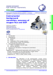
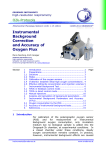
Agilent G1978B
Multimode Source for
6100 Series Single Quad
LC/MS
Set-Up Guide
Agilent Technologies
Notices
© Agilent Technologies, Inc. 2008
Warranty
No part of this manual may be reproduced in
any form or by any means (including electronic storage and retrieval or translation
into a foreign language) without prior agreement and written consent from Agilent
Technologies, Inc. as governed by United
States and international copyright laws.
The material contained in this document is provided “as is,” and is subject to being changed, without notice,
in future editions. Further, to the maximum extent permitted by applicable
law, Agilent disclaims all warranties,
either express or implied, with regard
to this manual and any information
contained herein, including but not
limited to the implied warranties of
merchantability and fitness for a particular purpose. Agilent shall not be
liable for errors or for incidental or
consequential damages in connection with the furnishing, use, or performance of this document or of any
information contained herein. Should
Agilent and the user have a separate
written agreement with warranty
terms covering the material in this
document that conflict with these
terms, the warranty terms in the separate agreement shall control.
Manual Part Number
G1978-90070
Edition
First Edition, December 2008
Printed in USA
Agilent Technologies, Inc.
5301 Stevens Creek Blvd.
Santa Clara, CA 95051 USA
Windows® and MS Windows® are U.S.
registered trademarks of Microsoft Corporation.
Windows NT® is a U.S. registered trademark of Microsoft Corporation.
Technology Licenses
The hardware and/or software described in
this document are furnished under a license
and may be used or copied only in accordance with the terms of such license.
Restricted Rights Legend
U.S. Government Restricted Rights. Software and technical data rights granted to
the federal government include only those
rights customarily provided to end user customers. Agilent provides this customary
commercial license in Software and technical data pursuant to FAR 12.211 (Technical
Data) and 12.212 (Computer Software) and,
for the Department of Defense, DFARS
252.227-7015 (Technical Data - Commercial
Items) and DFARS 227.7202-3 (Rights in
Commercial Computer Software or Computer Software Documentation).
2
Safety Notices
CAUTION
A CAUTION notice denotes a hazard. It calls attention to an operating procedure, practice, or the like
that, if not correctly performed or
adhered to, could result in damage
to the product or loss of important
data. Do not proceed beyond a
CAUTION notice until the indicated
conditions are fully understood and
met.
WA R N I N G
A WARNING notice denotes a
hazard. It calls attention to an
operating procedure, practice, or
the like that, if not correctly performed or adhered to, could result
in personal injury or death. Do not
proceed beyond a WARNING
notice until the indicated conditions are fully understood and
met.
Multimode Source for 6100 Series Single Quad LC/MS Set-Up Guide
In This Guide
This guide explains how to install, maintain and troubleshoot your
nanoelectospray ion source.
1
Installation
This chapter tells you how to install the multimode ion source.
2
Verification
This chapter tells you how to install the multimode ion source.
3
Methods
This chapter describes basic operation and maintenance for the multimode
ion source.
Multimode Source for 6100 Series Single Quad LC/MS Set-Up Guide
3
4
Multimode Source for 6100 Series Single Quad LC/MS Set-Up Guide
Content
1
Installation
7
Installation 8
Step 1. Prepare to install 8
Step 2. Install the HV control PCA and cables
9
Changing Sources 13
To remove the multimode source 13
To convert from multimode to ESI, APCI or APPI 14
To convert from ESI, APCI or APPI to the multimode source
2
Verification
15
21
To verify sensitivity for 6120 Quad - G1978B Multimode, Positive SIM
Modes 22
To verify sensitivity for 6130 and 6140 Quads - G1978B Multimode, Positive SIM
Modes 24
To verify sensitivity for 6130 and 6140 Quads - G1978B Multimode, Positive
Scan Modes 27
To verify sensitivity for the G1978B Multimode using Multiple FIA method in
Mixed Mode operation 30
To do an autotune 32
Example of multimode verification report 33
3
Methods
35
To setup a method to use the multimode source 36
To create a method for positive/negative mixed mode operation
To create a method for alternating ESI and APCI operation 39
Multimode Source for 6100 Series Single Quad LC/MS Set-Up Guide
37
5
Contents
6
Multimode Source for 6100 Series Single Quad LC/MS Set-Up Guide
Agilent G1978B Multimode Source for 6100 Series Single Quad LC/MS
Set-Up Guide
1
Installation
Installation 8
Step 1. Prepare to install 8
Step 2. Install the HV control PCA and cables 9
Changing Sources 13
To remove the multimode source 13
To convert from multimode to ESI, APCI or APPI 14
To convert from ESI, APCI or APPI to the multimode source 15
This chapter contains instructions to install the multimode source on a 6100
Series Single Quad LC/MS system, and also to remove and replace the source.
Agilent Technologies
7
1
Installation
Installation
Installation
This section explains how to install the G1978B multimode source on a 6100
Series Single Quad LC/MS instrument. The G1978A multimode source is not
supported on these instruments.
The 6100 Series Single Quad LC/MS with multimode source is supported on
ChemStation B.03.01 or higher, or the ChemStation B.01.03 with a patch.
Step 1. Prepare to install
The Multimode Enablement Kit, G1978-60451, is shipped with the multimode
source. This kit needs to be installed before the multimode source is used.
Note that the multimode source and its accessories are to be installed by an
Agilent Customer Engineer.
1 Check that the Multimode Enablement Kit contains the following parts:
• Multimode Bd HV cable, p/n G1960-60858
• Multimode HV PCA, p/n G1960-61015
• Multimode Bd Power/Data Cable, p/n G1960-60873
Figure 1
From left to right: G1960-60858, G1960-61015 and G1960-60873
2 Install the APCI Enablement Kit, G1947-60451, which is shipped with the
multimode source.
The APCI Enablement kit contains the following parts:
• Fast APCI HV Supply, p/n G1946-80058
8
Multimode Source for 6100 Series Single Quad LC/MS Set-Up Guide
Installation
Step 2. Install the HV control PCA and cables
1
• Valve BD-APCI supply, p/nG1960-60802
• Valve BD-APCI Needle Interlock, p/n G1960-60856
Figure 2
From left to right: G1946-80058, G1960-60802 and G1960-60856
Step 2. Install the HV control PCA and cables
1 Turn off the system power and remove the system power cord.
Keep the power cord intact if the vacuum control switch box is used. The
switch box is intended to keep the vacuum on while a CE works on the
electronics. The switch box is for CE use only.
2 Remove the CDS cover, top, side, front, and the Aux Module cover.
3 Disconnect the ribbon cable that connects the valve PCA to the
Vcap/Vchamber power supply. Then disconnect the Vcap and Vchamber
cable from the power supply.
Figure 3
Disconnecting the Vcap/Vchamber power supply from the valve PCA (left) and the Vcap/Vchamber.
4 Place the multimode HV power supply PCA in the slot between the valve
PCA and the Vcap/Vchamber. Secure the board by pressing it down into its
slot and then attach it with two screws.
5 Connect the short gray cable from valve PCA to the multimode HV power
supply.
Multimode Source for 6100 Series Single Quad LC/MS Set-Up Guide
9
1
Installation
Step 2. Install the HV control PCA and cables
Figure 4
Connecting the valve PCA to the multimode HV power supply.
6 Install the APCI HV power supply. The APCI HV power supply is located at
the end of the AUX Module.
7 Connect ribbon cable between valve PCA and Vcap/Vchamber power
supply.
Figure 5
Connecting the valve PCA to the Vcap/Vchamber power supply.
8 Connect the Vcap and Vchamber cables to the Vcap/Vchamber power
supply.
10
Multimode Source for 6100 Series Single Quad LC/MS Set-Up Guide
Installation
Step 2. Install the HV control PCA and cables
Figure 6
1
Connecting the Vcap and Vchamber cables to the power supply.
9 Connect the long ribbon cable, p/n G1960-60802, from the APCI HV power
supply to the valve PCA.
Figure 7
Connecting the APCI HV power supply to the valve PCA.
10 Insert one end of the APCI Needle Interlock cable, G1960-60856, through
the slot at the front of the system and then plug it to the APCI HV
connector. Attach the other end to the chassis with the o-ring and the nut.
Figure 8
Connecting the APCI HV to the chassis.
11 Insert the cable, G1960-60858, to the top slot and attach it to the chassis.
Plug the other two ends into the multimode HV PCA.
Multimode Source for 6100 Series Single Quad LC/MS Set-Up Guide
11
1
Installation
Step 2. Install the HV control PCA and cables
Figure 9
Connecting the HV PCA to the chassis.
12 Close the AUX Module cover and reconnect all cables.
13 Install the multimode source to the system and connect all connectors.
Figure 10
Installing the multimode source (left) and connecting all connectors.
14 Put back the side, top, front and CDS cover.
15 Plug the system power cord back on and turn the front switch on.
The pump down process will start.
16 Start the ChemStation program.
17 Click Method and Run Control View > MSD > Spray Chamber and verify
that the source is an MM Source.
18 Go to MSD Tune window and start the Auto tune with a multimode source.
19 Verify that the multimode source is working correctly.
12
Multimode Source for 6100 Series Single Quad LC/MS Set-Up Guide
Installation
Changing Sources
1
Changing Sources
To remove the multimode source
Do the following steps to remove the multimode source.
1 Set the source temperatures for vaporizer heater and drying gas heater to
minimum values to cool the source.
Use the Tune > Instrument > Edit Spray Chamber menu item to display
the Edit Spray Chamber dialog box. Set the drying gas flow, nebulizer gas
flow, drying gas temperature and the vaporizer temperature to minimum
values.
WA R N I N G
Do not touch the multimode source or the capillary cap. They may be very hot. Let
the parts cool before you handle them.
WA R N I N G
Never touch the source surfaces, especially when you analyze toxic substances or
when you use toxic solvents. The source has several sharp pieces which can pierce
your skin including the APCI corona needle, vaporizer sensor and counter current
electrode.
WA R N I N G
Do not insert fingers or tools through the openings on the multimode chamber. When
in use, the capillary and capillary cap are at high voltages up to 4 kV.
2 Wait approximately 20 minutes or until the source is cool.
3 Open the CDS door at the front of the MS to access the cables.
4 Disconnect the ESI high voltage charging electrode cable.
5 Disconnect the APCI Needle Interlock and multimode HV cable.
6 Unscrew the nebulizer gas line from the nebulizer.
7 Unscrew the LC sample tubing from the nebulizer.
8 Open the latch on the source and open the source.
9 Remove the multimode source from the spray chamber mount.
Multimode Source for 6100 Series Single Quad LC/MS Set-Up Guide
13
1
Installation
To convert from multimode to ESI, APCI or APPI
10 Place the source shipping cover on the source.
To convert from multimode to ESI, APCI or APPI
WA R N I N G
Never touch the source surfaces, especially when you analyze toxic substances or
when you use toxic solvents. The source has several sharp pieces which can pierce
your skin including the APCI corona needle, vaporizer sensor and counter current
electrode.
1 If the source to be installed is an APPI source, disconnect the multimode
high voltage PCA RS-232 serial cable from the serial port B connector of
Smart Card.
2 Unscrew and remove the multimode spray shield with the field shaping
electrodes.
3 Install the new source and the standard spray shield, making sure that the
hole in the spray shield is in the 12 o'clock position.
4 For APCI and APPI ion source, connect the vaporizer heater cable and the
APCI high voltage cable. For the APPI source, connect the RS-232 cable to
the serial port B connector of Smart Card.
5 For all sources, reconnect the nebulizer gas line tubing and the LC/MS
sample tubing.
14
Multimode Source for 6100 Series Single Quad LC/MS Set-Up Guide
Installation
To convert from ESI, APCI or APPI to the multimode source
1
To convert from ESI, APCI or APPI to the multimode source
CAUTION
If you are installing this source on this instrument for the first time, follow the steps in
“Installation” on page 7.
1 Switch to the MSD Tune view.
2 Select Instrument/Set Spray Chamber and set all gas flows and
temperatures to 0.
• Drying Gas (L/min)
• Nebulizer Pressure (psig)
• Drying Gas Temperature (°C)
• Vaporizer Temperature (APCI source only)
• Lamp Off (APPI source only)
3 Wait for the source to cool (until temperatures are at least below 100°C).
4 Disconnect the nebulizer gas tubing from the currently installed ion source.
5 Disconnect the LC/MS sample inlet tubing.
6 If the APCI or APPI source is installed, remove the APCI vaporizer heater
cable and APCI high voltage cable.
7 If the APPI source is installed, remove the serial port B RS-232 cable.
8 Remove the currently installed ion source.
9 Unscrew and remove the spray shield. See Figure 11.
WA R N I N G
Do not touch the multimode source or the capillary cap. They may be very hot. Let the
parts cool before you handle them.
WA R N I N G
Do not insert fingers or tools through the openings on the multimode chamber. When
in use, the capillary and capillary cap are at high voltages up to 4 kV.
Multimode Source for 6100 Series Single Quad LC/MS Set-Up Guide
15
1
Installation
To convert from ESI, APCI or APPI to the multimode source
Standard spray shield
Capillary cap
Figure 11
Standard spray shield and capillary cap for ESI or APCI
10 Remove the capillary cap. If needed, moisten a clean cloth with isopropyl
alcohol and wipe the capillary cap. See Figure 12.
Capillary cap
Figure 12
Spray shield removed.
11 Place the capillary cap back on the capillary.
12 Install the new spray shield with field shaping electrodes. See Figure 13.
16
Multimode Source for 6100 Series Single Quad LC/MS Set-Up Guide
Installation
To convert from ESI, APCI or APPI to the multimode source
Figure 13
1
Multimode spray shield
13 Screw the multimode spray shield into the holder for the spray shield. See
Figure 14.
Field shaping electrode
9 o'clock position
Field shaping electrode
6 o'clock position
Figure 14
NOTE
Multimode spray shield installed
The field shaping electrodes should be in the nine o’clock and the six o’clock position.
Loosen the end plate screws on each side to adjust the field shaping electrodes position.
14 Remove the shipping cover from the multimode source spray chamber.
Multimode Source for 6100 Series Single Quad LC/MS Set-Up Guide
17
1
Installation
To convert from ESI, APCI or APPI to the multimode source
Figure 15
Multimode Spray Chamber
15 Install the spray chamber on the spray chamber mount.
I-Button
Figure 16
Multimode source with I-Button
16 Install the nebulizer on the multimode source spray chamber.
18
Multimode Source for 6100 Series Single Quad LC/MS Set-Up Guide
Installation
To convert from ESI, APCI or APPI to the multimode source
Figure 17
1
No nebulizer on top of the multimode source
17 Connect the 1/8-inch nebulizer gas tubing from the LC/MS mainframe to
the nebulizer gas fitting. See Figure 18.
Sample Tubing
Nebulizer zero dead
volume
Nebulizer gas fitting
Figure 18
Nebulizer with gas tubing connected
Multimode Source for 6100 Series Single Quad LC/MS Set-Up Guide
19
1
Installation
To convert from ESI, APCI or APPI to the multimode source
18 Connect the LC/MS sample tubing to the LC/MS diverter valve inlet filter.
See Figure 19 on page 20.
WA R N I N G
The LC/MS Liquid Chromatograph diverter valve is an integral part of the G1978B
safety system. The LC mobile phase flow must always be connected to the diverter
valve inlet filter. Never bypass the diverter valve and connect directly to the
nebulizer. If the diverter valve is used in a manner not specified by Agilent
Technologies, the protections provided by the diverter valve may be impaired.
LC/MS sample tubing
Figure 19
LC/MS sample tubing connected to LC/MS inlet filter
19 If you are installing the multimode source for the first time, follow the steps
in “Step 2. Install the HV control PCA and cables” on page 9.
20
Multimode Source for 6100 Series Single Quad LC/MS Set-Up Guide
Agilent G1978B Multimode Source for 6100 Series Single Quad LC/MS
Set-Up Guide
2
Verification
To verify sensitivity for 6120 Quad - G1978B Multimode, Positive SIM
Modes 22
To verify sensitivity for 6130 and 6140 Quads - G1978B Multimode, Positive
SIM Modes 24
To verify sensitivity for 6130 and 6140 Quads - G1978B Multimode, Positive
Scan Modes 27
To verify sensitivity for the G1978B Multimode using Multiple FIA method
in Mixed Mode operation 30
To do an autotune 32
Example of multimode verification report 33
This chapter contains instructions to verify your G1978B multimode a 6100
Series Single Quad LC/MS instrument.
Agilent Technologies
21
2
Verification
To verify sensitivity for 6120 Quad - G1978B Multimode, Positive SIM Modes
To verify sensitivity for 6120 Quad - G1978B Multimode, Positive
SIM Modes
NOTE
The G6110A instrument does not support the multimode source without the Selection
valve. Use the option kit G2735H to enable the G6110A to work with the multimode source.
Preparation
1 Transfer 1 mL of 5 ng/µL reserpine (Agilent G2423A) to a 50 mL volumetric
flask. Use a clean graduated pipette.
2 Dilute to the 50 mL mark with 75:25 methanol/water with 0.1% formic or
acetic acid.
3 Transfer 1 mL of the first dilution to a second 50 mL volumetric flask. Use a
clean graduated pipette.
4 Dilute to the 50 mL mark with 75:25 methanol/water with 0.1% formic or
acetic acid.
This provides the final 2 pg/µL reserpine concentration required for
performance verification.
5 Transfer approximately 1 mL of the second dilution to a vial for use in the
LC autosampler.
Table 1
22
6110 and 6120 Quad Performance Verification Summary Table
G1978B
ES Positive SIM Mode
G1978B
APCI Positive SIM Mode
Sample
Reserpine, 5 ng/µL
Reserpine, 5 ng/µL
Concentration after dilution
2 pg/µL
2 pg/µL
Injection volume
5 µL
5 µL
Total sample amount injected
10 pg
10 pg
Sample order number
G2423A
G2423A
Solvent
75:25
methanol/water
with 0.1% formic or acetic acid
75:25
methanol/water
with 0.1% formic or acetic acid
Multimode Source for 6100 Series Single Quad LC/MS Set-Up Guide
Verification
To verify sensitivity for 6120 Quad - G1978B Multimode, Positive SIM Modes
Table 1
2
6110 and 6120 Quad Performance Verification Summary Table
Method name
Performance Specification
G1978B
ES Positive SIM Mode
G1978B
APCI Positive SIM Mode
6110SIMES_MM.M
(6110 Quad)
6110SIMCI_MM.M
(6110 Quad)
6120SIMES_MM.M
(6120 Quad)
6120SIMCI_MM.M
(6120 Quad)
20: 1 pk-pk
100: 1 rms
10: 1 pk-pk
50: 1 rms
Sensitivity Verification for Multimode in ESI Positive SIM Mode
1 Start up the ChemStation software.
2 Change the view to MSD Tune, and start an Autotune.
After the autotune completes, you may need to wait up to 30 minutes to
allow for the calibrant solution to be pumped out of the Quad instrument.
This minimizes any background signal resulting from the calibrant.
3 Change the view to Method and Run Control, and load the method
6120SIMES_MM.M (6120 model).
4 Edit the method to ensure that 75:25 methanol/water with 0.1% formic or
acetic acid is selected as the LC solvent.
5 Place the vials into the LC autosampler.
• Position #1: empty, uncapped vial
• Position #2: vial of the solvent used for dilution (solvent blank)
• Position #3: vial with the reserpine sample (2 pg/µL)
6 Run the method.
The method does an FIA run with one injection of the empty vial, five
injections of the solvent blank, and five injections of the reserpine sample.
You may need to further optimize the nebulizer pressure by running FIA
experiments to achieve maximum instrument sensitivity.
7 Review the results.
Multimode Source for 6100 Series Single Quad LC/MS Set-Up Guide
23
2
Verification
To verify sensitivity for 6130 and 6140 Quads - G1978B Multimode, Positive SIM Modes
When the method is finished, a report prints showing the signal-to-noise ratio
for the five blank and five sample peaks, and a blank-subtracted average of the
sample peaks. The blank-subtracted average signal-to-noise value must be
greater than or equal to 20:1 peak-to-peak (100:1 RMS).
To verify sensitivity for 6130 and 6140 Quads - G1978B Multimode,
Positive SIM Modes
Preparation
1 Transfer 1 mL of 5 ng/µL reserpine (Agilent G2423A) to a 50 mL volumetric
flask. Use a clean graduated pipette.
2 Dilute to the 50 mL mark with 75:25 methanol/water with 5 mM ammonium
formate.
3 Transfer 1mL of the first dilution to a 100 mL volumetric flask. Use a clean
graduated pipette.
4 Dilute to the 100 mL mark with 75:25 methanol/water with 5 mM
ammonium formate.
This provides the final 1 pg/µL reserpine concentration required for performance verification.
5 Transfer approximately 1 mL of the second dilution to an autosampler vial.
Table 2
24
6130 and 6140 Quad Performance Verification Summary, SIM Mode
G1978B
ES Positive SIM Mode
G1978B
APCI Positive SIM Mode
Sample
Reserpine, 5 ng/µL
Reserpine, 5 ng/µL
Concentration after dilution
1 pg/µL
1 pg/µL
Injection volume
1 µL
1 µL
Total sample amount injected
1 pg
1 pg
Sample order number
G2423A
G2423A
Multimode Source for 6100 Series Single Quad LC/MS Set-Up Guide
Verification
To verify sensitivity for 6130 and 6140 Quads - G1978B Multimode, Positive SIM Modes
Table 2
2
6130 and 6140 Quad Performance Verification Summary, SIM Mode
G1978B
ES Positive SIM Mode
G1978B
APCI Positive SIM Mode
Solvent
75:25
methanol/water
with 5mM
ammonium formate
75:25
methanol/water
with 5mM
ammonium formate
Method name
6130SIMES_MM.M
(6130 model)
6130SIMCI_MM.M
(6140 model)
6140SIMES_MM.M
(6140 model)
6140SIMCI_MM.M
(6140 model)
20: 1 pk-pk
100: 1 rms
10: 1 pk-pk
50: 1 rms
Performance Specification
Sensitivity Verification for Multimode in ESI, Positive SIM Mode
1 Start up the ChemStation software.
2 Change the view to MSD Tune, and start an Autotune.
After the autotune completes, you may need to wait up to 30 minutes to
allow for the calibrant solution to be pumped out of the Quad instrument.
This minimizes any background signal resulting from the calibrant.
3 Change the view to Method and Run Control, and load the method
6130SIMES_MM.M (6130 model) or 6140SIMES_MM.M (6140 model).
4 Edit the method to ensure that 75:25 methanol/water with 5mM ammonium
formate is selected as the LC solvent.
5 Place the vials into the LC autosampler.
• Position #1: empty, uncapped vial
• Position #2: vial of the solvent used for dilution (solvent blank)
• Position #3: vial with the reserpine sample (1 pg/µL)
6 Run the method.
The method does an FIA run with one injection of the empty vial, five
injections of the solvent blank, and five injections of the reserpine sample.
You may need to further optimize the nebulizer pressure by running FIA
Multimode Source for 6100 Series Single Quad LC/MS Set-Up Guide
25
2
Verification
To verify sensitivity for 6130 and 6140 Quads - G1978B Multimode, Positive SIM Modes
experiments to achieve maximum instrument sensitivity
7 Review the results.
When the method is finished, a report prints showing the signal-to-noise ratio
for the five blank and five sample peaks, and a blank-subtracted average of the
sample peaks. The blank-subtracted average signal-to-noise value must be
greater than or equal to 20:1 peak-to-peak (100:1 RMS).
Sensitivity Verification for Multimode in APCI, Positive SIM Mode
1 Start the ChemStation software.
2 Change the view to MSD Tune, and start an Autotune.
After the autotune completes, you may need to wait up to 30 minutes before
you continue, to allow for the calibrant solution to be pumped out of the
Quad instrument. This minimizes any background signal resulting from the
calibrant.
3 Change the view to Method and Run Control, and load the method
6130SIMCI_MM.M (6130 model) or 6140SIMCI_MM.M (6140 model)
4 Edit the method to ensure that 75:25 methanol/water with 5mM ammonium
formate is selected as the LC solvent.
5 Place the vials into the LC autosampler.
• Position #1: empty, uncapped vial
• Position #2: vial of the solvent used for dilution (solvent blank)
• Position #3: vial with the reserpine sample (1 pg/µL)
6 Run the method.
You may need to further optimize the nebulizer pressure by running FIA
experiments to achieve maximum instrument sensitivity
The method does an FIA run with one injection of the empty vial, five
injections of the solvent blank, and five injections of the reserpine sample.
7 Review the results.
When the method is finished, a report prints showing the signal-to-noise ratio
for the five blank and five sample peaks, and a blank-subtracted average of the
sample peaks. The blank-subtracted average signal-to-noise value must be
greater than or equal to 10:1 peak-to-peak (50:1 RMS).
26
Multimode Source for 6100 Series Single Quad LC/MS Set-Up Guide
Verification
To verify sensitivity for 6130 and 6140 Quads - G1978B Multimode, Positive Scan Modes
2
To verify sensitivity for 6130 and 6140 Quads - G1978B Multimode,
Positive Scan Modes
Preparation
1 Transfer 1 mL of 5 ng/µL reserpine (Agilent G2423A) to a 50 mL volumetric
flask. Use a clean graduated pipette.
2 Dilute to the 50 mL mark with 75:25 methanol/water with 5 mM ammonium
formate.
3 Transfer 5 mL of the first dilution to a 50 mL volumetric flask. Use a clean
graduated pipette.
4 Dilute to the 50 mL mark with 75:25 methanol/water with 5 mM ammonium
formate.
This provides the final 10 pg/µL reserpine concentration required for
performance verification.
5 Transfer approximately 1 mL of the second dilution to an autosampler vial.
Table 3
6130 and 6140 Quad Performance Verification Summary, Scan Mode
G1978B
ES Positive Scan Mode
G1978B
APCI Positive Scan Mode
Sample
Reserpine, 5 ng/µL
Reserpine, 5 ng/µL
Concentration after dilution
10 pg/µL
10 pg/µL
Injection volume
5 µL
5 µL
Total sample amount injected
50 pg
50 pg
Sample order number
G2423A
G2423A
Solvent
75:25
methanol/water
with 5mM
ammonium formate
75:25
methanol/water
with 5mM
ammonium formate
Multimode Source for 6100 Series Single Quad LC/MS Set-Up Guide
27
2
Verification
To verify sensitivity for 6130 and 6140 Quads - G1978B Multimode, Positive Scan Modes
Table 3
6130 and 6140 Quad Performance Verification Summary, Scan Mode
Method name
Performance Specification
G1978B
ES Positive Scan Mode
G1978B
APCI Positive Scan Mode
6130SCNES_MM.M
(6130 Quad)
6130SCNCI_MM.M
(6130 Quad)
6140SCNES_MM.M
(6140 Quad)
6140SCNCI_MM.M
(6140 Quad)
20: 1 pk-pk
100: 1 rms
10: 1 pk-pk
50: 1 rms
Sensitivity Verification for Multimode in ESI, Positive Scan Mode
1 Start the ChemStation software.
2 Change the view to MSD Tune, and start an Autotune.
After the autotune completes, you may need to wait up to 30 minutes to
allow for the calibrant solution to be pumped out of the Quad instrument.
This minimizes any background signal resulting from the calibrant.
3 Change the view to Method and Run Control, and load the method
6130SCNES_MM.M (for 6130) or 6140SCNES_MM.M (for 6140).
4 Edit the method to ensure that 75:25 methanol/water with 5mM ammonium
formate is selected as the LC solvent.
5 Place the vials into the LC autosampler.
• Position #1: empty, uncapped vial
• Position #2: vial of the solvent used for dilution (solvent blank)
• Position #3: vial with the reserpine sample (10 pg/µL)
6 Run the method.
You may need to further optimize the nebulizer pressure by running FIA
experiments to achieve maximum instrument sensitivity.
The method does an FIA run with one injection of the empty vial, five
injections of the solvent blank, and five injections of the reserpine sample.
7 Review the results.
28
Multimode Source for 6100 Series Single Quad LC/MS Set-Up Guide
Verification
To verify sensitivity for 6130 and 6140 Quads - G1978B Multimode, Positive Scan Modes
2
When the method is finished, a report prints showing the signal-to-noise
ratio for the five blank and five sample peaks, and a blank-subtracted
average of the sample peaks. The blank-subtracted average signal-to-noise
value must be greater than or equal to 20:1 peak-to-peak (100:1 RMS).
Sensitivity Verification for Multimode in APCI, Positive Scan Mode
1 Start the ChemStation software.
2 Change the view to MSD Tune, and start an Autotune.
After the autotune completes, you may need to wait up to 30 minutes to
allow for the calibrant solution to be pumped out of the Quad instrument.
This minimizes any background signal resulting from the calibrant.
3 Change the view to Method and Run Control, and load the method
6130SCNCI_MM.M (6130 model) or 6140SCNCI_MM.M (6140 model).
4 Edit the method to ensure that 75:25 methanol/water with 5mM ammonium
formate is selected as the LC solvent.
5 Place the vials into the LC autosampler.
• Position #1: empty, uncapped vial
• Position #2: vial of the solvent used for dilution (solvent blank)
• Position #3: vial with the reserpine sample (10 pg/µL)
6 Run the method.
The method does an FIA run with one injection of the empty vial, five
injections of the solvent blank, and five injections of the reserpine sample.
You may need to further optimize the nebulizer pressure by running FIA
experiments to achieve maximum instrument sensitivity
7 Review the results.
When the method is finished, a report prints showing the signal-to-noise ratio
for the five blank and five sample peaks, and a blank-subtracted average of the
sample peaks. The blank-subtracted average signal-to-noise value must be
greater than or equal to 10:1 peak-to-peak (50:1 RMS).
Multimode Source for 6100 Series Single Quad LC/MS Set-Up Guide
29
2
Verification
To verify sensitivity for the G1978B Multimode using Multiple FIA method in Mixed Mode operation
To verify sensitivity for the G1978B Multimode using Multiple FIA
method in Mixed Mode operation
Preparation
1 Do an autotune if necessary.
After the autotune has completed, you may need to wait up to 30 minutes
before continuing to allow the calibrant solution to be pumped out of the
Quad instrument. This minimizes any background signal from the calibrant.
You may need to further optimize the nebulizer pressure to achieve
maximum instrument sensitivity.
2 Load the method MMCheckSL_ES.M and:
a Edit the method to ensure that 65:35 methanol/water with .2% acetic acid
is selected as the LC solvent.
b Save the method.
3 Repeat for MMCheckSL_CI.M and MMCheckSL_MX.M.
4 Place the vial into the LC autosampler.
• Position 21: vial with the ESI + APCI LC Demo Sample (p/n
G1978-85000)
Create and run a Multiple FIA Method Sequence
1 Select RunControl > Run Multiple FIA Methods.
2 In the Run Multiple FIA Methods dialog box, click Group > Add Group.
3 Type in a unique directory name for the data files to be stored.
4 In the Run Multiple FIA Methods dialog box, click Methods > Add Method,
select MMCheckSL_ES.M and click OK.
5 Repeat to add MMCheckSL_CI.M.
6 Repeat to add MMCheckSL_MX.M.
7 Click Data File for the MMCheckSL_ES.M data file, then:
a Change the Subdirectory value to a unique subdirectory name in which
to store the data files.
b Change Data File to Multi_ES.
c Change Operator to the user’s name or identification code.
30
Multimode Source for 6100 Series Single Quad LC/MS Set-Up Guide
Verification
To verify sensitivity for the G1978B Multimode using Multiple FIA method in Mixed Mode operation
2
d Click OK.
8 Repeat for the MMCheckSL_CI.M data file. Use the same subdirectory and
change Data File to Multi_CI.
9 Repeat for the MMCheckSL_MX.M data file. Use the same subdirectory and
change Data File to Multi_MX as the data file name.
10 Click Run to start the sequence.
11 Review the results.
When the last method has finished, the report “Multimode Verification Report”
prints.
Multimode Source for 6100 Series Single Quad LC/MS Set-Up Guide
31
2
Verification
To do an autotune
To do an autotune
Tuning the multimode source is done in MM-APCI mode only. Autotune is
done from the same menu as with all sources.
• From the MSD Tune view, select Instrument > Autotune menu item.
The tune report will have a header with either the title MM-APCI Positive
Mode - Standard Scan or MM-APCI Negative Mode - Standard Scan. You can
run the check tune after an autotune to validate that the instrument passes
check tune criteria. Do the autotune after the system has had at least 8 hours
to equilibrate vacuum and temperatures.
Figure 20
32
Autotune report
Multimode Source for 6100 Series Single Quad LC/MS Set-Up Guide
Verification
Example of multimode verification report
2
Example of multimode verification report
Multimode Source for 6100 Series Single Quad LC/MS Set-Up Guide
33
2
34
Verification
Example of multimode verification report
Multimode Source for 6100 Series Single Quad LC/MS Set-Up Guide
Agilent G1978B Multimode Source for 6100 Series Single Quad LC/MS
Set-Up Guide
3
Methods
To setup a method to use the multimode source 36
To create a method for positive/negative mixed mode operation 37
To create a method for alternating ESI and APCI operation 39
This chapter describes the tasks that you need to set up methods for the
multimode source. See “Guidelines” in the Agilent G1978A/B Multimode
Source Maintenance Guide for suggested source conditions for the multimode
source for the different ionization modes.
Agilent Technologies
35
3
Methods
To setup a method to use the multimode source
To setup a method to use the multimode source
To have your method use a multimode source, follow these steps:
1 Open the MSD Spray Chamber dialog box by clicking Instrument > MSD
Spray Chamber in the Method and Run Control view.
2 Set Method Spray Chamber to MM-ES+APCI.
3 Verify that Installed Spray Chamber is set to MM-ES+APCI.
4 Make any other changes that are necessary for your method.
5 Click the OK button.
6 Open The Set up MSD Signals dialog box by clicking Instrument > More >
Set up MSD Signals in the Method and Run Control view.
7 Choose the desired ionization mode from the Ionization list. This list is
only visible if the Method Spray Chamber was set to MM-ES+APCI. You
may set the ionization mode to one of the following:
• MM-ES
• MM-APCI
• MM-ES+APCI
8 Make any other changes that are necessary for your method.
9 Click the OK button.
WA R N I N G
36
The 6100 Series Single Quad LC/MS Liquid Chromatograph diverter valve is an
integral part of the G1978B safety system. The LC mobile phase flow must always be
connected to the diverter valve inlet filter. Never bypass the diverter valve and
connect directly to the nebulizer. If the diverter valve is used in a manner not
specified by Agilent Technologies, the protections provided by the diverter valve may
be impaired and the system may catch fire.
Multimode Source for 6100 Series Single Quad LC/MS Set-Up Guide
Methods
To create a method for positive/negative mixed mode operation
3
To create a method for positive/negative mixed mode operation
1 Open the MSD Spray Chamber dialog box by clicking the Instrument > Set
Up MSD Signals in the Method and Run Control view.
2 Select MM-ES_APCI from the Method Spray Chamber drop-down list.
3 Check that Installed Spray Chamber is also set to MM-ES+APCI.
4 Make any other changes that are necessary for your method.
5 Click the OK button.
6 Open the Set up MSD Signals dialog box by clicking the Instrument > MSD
Spray chamber in the Method and Run Control view.
7 Modify the settings so that Signal 1 has Positive polarity and Signal 2 has
Negative polarity as shown in Figure 21.
8 Make any other changes that are necessary for your method.
9 Click the OK button.
Fast positive/negative polarity switching is a very useful technique but it
requires time for the ion chemistry to be established and the optics path to
refill with ions. The gas density plays a role in the speed of refilling the ion
path. The gas density is affected by source temperature. For a method running
positive/negative switching, use a lower vaporizer temperature (150 to 200°C)
and a lower Vcap (approximately 1000 V). These will greatly affect the quality
of the results in positive/negative switching experiments.
Multimode Source for 6100 Series Single Quad LC/MS Set-Up Guide
37
3
Methods
To create a method for positive/negative mixed mode operation
Polarity options for
Signal 1 and Signal 2
Figure 21
38
Positive/Negative polarity switching using Set Up MSD Signals dialog box
Multimode Source for 6100 Series Single Quad LC/MS Set-Up Guide
Methods
To create a method for alternating ESI and APCI operation
3
To create a method for alternating ESI and APCI operation
1 Open The MSD Spray Chamber dialog box by clicking Instrument > MSD
Spray Chamber in the Method and Run Control view.
2 Set Method Spray Chamber to MM-ES+APCI.
Figure 22
Method Spray Chamber set to MM-ES+APCI.
3 Check that Installed Spray Chamber is also set to MM-ES+APCI.
4 Make any other changes that are necessary for your method.
5 Click the OK button.
6 Open the Set up MSD Signals dialog box by clicking Instrument > Set Up
MSD Signals in the Method and Run Control view.
7 Modify the settings so that Signal 1 has Ionization value of MM-ES and
Signal 2 has Ionization value of MM-APCI as shown in Figure 23.
8 Make any other changes that are necessary for your method.
Multimode Source for 6100 Series Single Quad LC/MS Set-Up Guide
39
3
Methods
To create a method for alternating ESI and APCI operation
9 Click the OK button.
NOTE
In general, use the mixed mode operation (MM-ES+APCI setting with Signal 1) instead of
alternating MM-ES (Signal 1) and MM-APCI (Signal 2) mode switching. Two times as many
scans are obtained during elution of a chromatographic peak, and no delay is needed
between scans, resulting in better data. It is rarely necessary to know whether a compound
responds purely in ESI or APCI modes on a chromatographic time scale.
Ionization mode for
Signal 1 and Signal 2
Figure 23
40
MM-ES and MM-APCI switching using Set Up MSD Signals dialog box
Multimode Source for 6100 Series Single Quad LC/MS Set-Up Guide
Index
Index
A
autotune, 32
C
converting from ESI, APCI or APPI, 15
converting to ESI or APCI, 14
D
diverter valve inlet filter, 20
E
ESI
convert from, 15
convert to, 14
I
installation, 7, 21
L
LC/MSD sample tubing, 20
M
method
alternating ESI and APCI, 39
basic setup, 36
positive/negative mixed mode, 37
multimode
nebulizer, 19
source image, 35
P
parts
multimode spray shield, 17
S
spray shield for multimode source, 17
Multimode Source for 6100 Series Single Quad LC/MS Set-Up Guide
41
Index
42
Multimode Source for 6100 Series Single Quad LC/MS Set-Up Guide
www.agilent.com
In This Book
This book contains
installation, operation,
maintenance and
troubleshooting instruction
for the Multimode Source
for 6100 Series Single Quad
LC/MS.
© Agilent Technologies, Inc. 2008
Printed in USA
First Edition, December 2008
*G1978-90070*
G1978-90070
Agilent Technologies