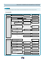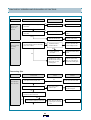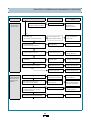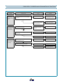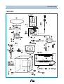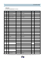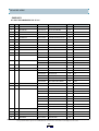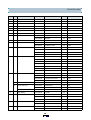
1
S/M No. : WM500SE000
Service Manual
Washing Machine
Model: DWM-500M
DWM-501M
✔ Caution
: In this Manual, some parts can be changed for improving, their
performance without notice in the parts list. So, if you need the
latest parts information,please refer to PPL(Parts Price List) in
Service Information Center (http://svc.dwe.co.kr).
DAEWOO ELECTRONICS CO., LTD.
http : //svc.dwe.co.kr
Aug. 1999
SPECIFICATIONS ............................................................................................................................... 2
CAUTIONS ON THE OPERATION...................................................................................................... 3
WIRING AND CIRCUIT DIAGRAM ..................................................................................................... 5
PRINCIPLES OF OPERATION AND EXPLANATION OF FUNCTIONS............................................ 8
HOW TO DISASSEMBLE.................................................................................................................... 16
EXPLODED VIEWS AND RECOMMENDABLE PARTS .................................................................... 19
SPECIFICATIONS
NO
1
POWER SOURCE
2
P O W E R C O N S U M PT IO N
3
SPECIFICATIONS
ITEM
M A C HIN E W E IG HT
4
D IM EN S IO N
5
C A PA C IT Y
50H Z
60H Z
Available in all local AC voltage
N O N PU M P
330W
PUMP
410W
N O N PU M P
NE T : 17.0kg,
PA C K E D U P : 18.5kg
PUMP
NE T : 18.0kg,
PA C K E D U P : 19.5kg
680 x 406 x 857 (W xD xH , m m )
WASH
3.0 kg
S P IN
2.7 kg
6
W AT ER LE VE L
7
O P E RATIN G W AT E R P R E S SU R E
8
R O TAT IN G S P E ED
HIG H : 37
,
LO W : 27
0.3 ~ 3.0kgf/cm 2 ( 3.0 ~ 30.0 N /cm 2)
WASH
330 rpm
340 rpm
S P IN
1,450 rpm
1,700 rpm
9
W AS H IN G T Y P E
P ulsator (Im peller) Type
10
S P IN NIN G TY P E
Centrifugally S eparated Type
11
W AS H T IM E
M ax. 15m in., M anual O peration
12
S P IN T IM E
M ax. 15m in., M anual O peration
13
P U LSATO R
14
W AT ER S U PP LY
6 W IN G S (
200 m m )
M A N UA L
Explanation table for suffixes of model names
PO WER SOURCE
SUFFIX
NON PUMP
PUMP
A C 110V, 60H z
T
TP
A C 220V, 60H z
L
LP
A C 110/220V, 50Hz
D
DP
A C 127/220V, 60H z
S
-
A C 220V, 50H z
N
NP
A C 230~240V, 50H z
M
MP
A C100V, 50/60H z
J
-
EXAM PLE
M odel nam e
D W -X X X XN P
P ow er soure
PUMP
CAUTIONS ON THE OPERATION
1. Installation
- Install the washer in the place easy of access to water, electrical pow er and drainage.
- Install the washer on a firm and flat floor.
- Be sure that the washing m achine m ust be grounded with the external grounding wire(option) or w ith the power cord
and electric outlet of the house.
- Avoid installing the m achine w here it can be exposed to rain or direct ray of the sun, that m ay cause trouble or
discoloration. In case the m achine has to be installed in such a place, provide a shield to protect m achine from rain
or direct rays of the sun.
- In sum m er or other periods when there is a great difference between the water tem perature and the air tem perature,
drops of water may condense on the outside of the tub, and the floor might become wet from dripping; be careful of this.
- Please disconnect the power cord plug after washing.
2. Grounding
- Connect the grounding w ire(option) to a water faucet if the pipe is m ade of m etal.
- M ake sure that the power cord is unplugged during ground work.
- Be sure to wind grounding wire on a m etal pipe like Fig1.
(Do not connect the grounding wire end to a gas tube.)
- For m axim um security, attach the grounding wire to a copper plate or grounding rod and bury it at least 20cm in the
ground like Fig2.
Fig. 1
Fig.2
CAUTIONS ON THE OPERATION
3. Caution on Use
- Do not use water which contains rust.
- Never put your hands into the tub during wash and rinse process.
- This unit is m ade of poly-propylene, use water below 50 .
- The opening m ust not be obstructed by carpeting when the washing m achine is installed on a carpeted floor.
- Put the wet clothes into the spindryer drum , being sure that they m ust be well balanced.
- Place the safety cover horizontally on the top.
- Ensure that the spindryer drum com pletely stops before reaching in to rem ove the laundry.
Detergent Amount
Putting in the clothes
If you use too m uch
detergent. There will be an
excessive amount of suds
and rinsing m ay be
insufficient: limit the
am ount of detergent you use.
Distribute the clothes in
the tub being sure that
nothing is protruding
out of the top.
Pocket Check
Acting Time Of Pulsator
Check the pockets of the
laundry and remove
contents that shouldn’t
be washed before putting
the laundry into the tub.
W ash
Action
M ove
Stop
Normal
Reverse
6.8”
4.5”
WIRING AND CIRCUIT DIAGRAM
1. SINGLE VOLTAGE NON PUMP MODEL
2. DUAL VOLTAGE NON PUMP MODEL
5
WIRING AND CIRCUIT DIAGRAM
3. SINGLE VOLTAGE PUMP MODEL
4. DUAL VOLTAGE PUMP MODEL
6
WIRING A ND C IRC UIT DIA G RA M
5. SINGLE VOLTAGE PUMP MODEL WITH TERMINAL BLOCK
6. SINGLE VOLTAGE NON PUMP MODEL(ONLY FOR JAPAN)
7
PRINCIPLES OF OPERATION AND EX PLANATION OF FUNCTIONS
TIMER WASH
- Function
The m ain switch(T1) rem ains ON during the washing tim e set by turning the tim er knob.
At the sam e tim e, the internal switch(T2, T3) provides Power to wash m otor alternately at assigned intervals.
Circuit Diagram
BLACK
T1
T2
M AIN
AC(V)
VIOLET
BLUE
M
309 (MAX S ET)
900'' 12 0 ( 300 SET )
T1
Main
T2
W ASH
M OTO R
PRINCIPLES OF OPERATION AND EXPLANATION OF FUNCTIONS
TIMER SPIN(OPTION)
- Function
The Spin Tim er is the switch providing power to the spin m otor(Drain Pum p m otor) during the set spin dry tim e,
and is a spring-type tim e sw itch com es on upon turning and those contact point com es off after the set tim e.
Structure and Principle of Activation
1. The m ain shaft turns due to the unwinding force when the spin tim er is turned and the spring wound, with that force
being delivered through each gear and the spring slow ly unwinding at a speedfinally controlled by the angle
assem bly.
2. The contact point turns ON and the assem bly angle is set in m otion, which is in the CAM groove in the OFF state,
com es off the groove when the M AIN SHAFT is turned to wind the spring. The contact point turns OFF, return to
CAM groove when the spring unwind com pletely.
SAFETY D EVICE FOR MO TORS(OPTION)
In case excessive strain is placed on the m otor
due to excessive electricity, over heating, or
overloading so that the tem perature of m otor
(Violet)
the therm al protector
reaches to about 130
attached to the m otor shuts off the m otor
autom atically. In the case the m otor does not
operate, until the tem perature of m otor drops to
about 85
(W hite)
. It takes about an hour.
(Blue)
SAFETY DEVIC E FOR SPIN D RYER
The spin dryer is an apparatus w hich elim inates the water from the laundry through centrifugal separation
generated by rapid revolution(approxim ately 1700rpm for frequency of 60H z).
Accordingly, there are a door sw itch to cut off the power going into the spin m otor when door spin o is opened and
a brake system to stop the rotating spin dryer.
PRINCIPLES OF OPERATION AND EXPLANATION OF FUNCTIONS
- Door Sw itch
W hen the door spin o is opened during spin drying the lever of the door switch which sites atop the door spin o
falls off the contact, and cuts off the power going into the spin m otor.
- Brake System
W hen the door spin is opened, the link brake and brake wire is loosened.
A nd then the brake band touches the drum coupling assem bly and stops the spin dryer as it is pulled by the
spring in the brake fix plate assem bly.
D O O R SP IN O
PA NE L B
PANEL B
DO OR S W ITCH
LINK BR AK E
SPIN DR Y ER
DOOR SPIN O
BR A KE W IR E
(IN NE R W IR E )
B ASE
DOO R SW ITCH
LEV ER
SPRING
DRUM
C O U PLIN G
W IR E G UID E
BR AKE W IRE
(O U TER W IRE )
BR AK E BA ND
BR AK E FIX
PLATE
LEVE R B R AKE
- Brake Band Gap C ontrol
The band brake w orks best when the gap between it and the drum coupling is about 2m m when the door spin is
closed. The spin dryer stops slowly if the gap is too large.
- SPIN B ELLOW S ASS'Y
The wrinkled rubber device below the spindryer
is called spin bellows assem bly.
It has a waterseal and an oilless m etal inside to
prevent leakage and so that spin dryer m ay work
sm oothly.
DRAIN PUMP OPERATION (Pump Model Only)
- Always running during Tim er is ON .
PRINCIPLES OF OPERATION AND EXPLANATION OF FUNCTIONS
NOTE
P ull out the pow er plug prior repair and m ake sure that the W ashing M achine has been properly grounded.
- Concerning Wash
Problem
Cause
Check Point
NO
Is the Power properly connected?
Pulsator does
not rotate.
Solution
Reconnect the Power Cord.
YES
YES
Is there a whirring sound from the
W ash Motor when turned on?
Is this Wash Selector
properly positioned?
NO
Set the W ash Selector
to W ASH RINSE
YES
Is the Condenser properly
connected?
NO
M otor does not start due
to opening the Condenser
circuit.
Reconnect the Condenser.
NO
Is the Motor hot?
(In case there is Therm al Protector)
YES
Power has been cut off
by the Thermal Protector
Power restored when
Motor cools
NO
NO
Is the W iring good?
(Refer to the W iring Diagram )
Improper wiring.
Reconnect the wiring.
Defective W ash Timer.
Replace W ash Timer.
Defective W ash M otor.
Replace W ash M otor.
YES
Is the contact of W ash Timer good?
NO
YES
NO
Is the wash load appropriate?
Pulsator does not
rotate sm oothly.
Reload with proper wash
load.
YES
Are the Pulsator and M otor Pulley
securely assembled?
NO
Defect of m echanical
assem bly.
Tighten the screws fixed
on the Pulley.
W orn out V-Belt.
Replace V-Belt
YES
Revolution obstructed by
im purities.
Rem ove im purities after
disassem bling pulsator.
YES
W orn out the Serration
within the pulsator.
Replace pulsator.
Defective Case Shaft As.
Replace Case Shaft As..
YES
YES
Does the V-Belt slip?
NO
Are there impurities between the
Pulsator and Tub.
NO
Does the pulsator shaft rotate propely
when the pulsator has been
disassem bled?
NO
PRINCIPLES OF OPERATION AND EXPLANATION OF FUNCTIONS
Problem
Check Point
Cause
NO
Is the wiring of Condenser properly
connected?
Pulsator rotate
only in one
direction.
Solution
Improper wiring.
Reconnect.
Improper wiring.
Reconnect the Wash
Timer
Defective Wash timer.
Replace Wash Timer.
Impurtities between
Pulsator and Tub.
Remove im purities after
disassembling Pulsator.
YES
Is the wiring of wash timer properly
connected?
NO
YES
Are there strange noise from Tub when
the Pulsator rotates?
There is excessive
noise during
washing.
YES
NO
Pulsator im properly
assem bled.
NO
Tighten the Pulsator fixing
screw.
Som ething is in contact
with the Pulsator Pulley or
M otor Pulley or other
rotationg parts.
Adjust the parts so that
there are no im purities in
contact with rotating parts.
Cause
Solution
Concerning Spin
Problem
Check Point
NO
Is the Spin Selector properly set?
The Spin Dryer
does not rotate.
Set the Spin Selector to SPIN
YES
YES
Is the Door Spin *O open?
The contact of Door
Switch is open.
Keep the Door Spin *O
closed during spin.
Motor does not start due
to opening the Condenser
circuit.
Reconnect.
NO
Is there a whirring sound form the
Spin Motor when turned ON?
YES
NO
NO
Is the Condenser properly connected?
YES
PRINCIPLES OF OPERATION AND EXPLANATION OF FUNCTIONS
Problem
Cause
Check P oint
S olution
YES
The Brake Band is touching
the Drum coupling Assembly.
The Spin Dryer
does not rotate.
Brake wire is too long
Assemble after loosening
Link Brake and
adjusting downward.
Power has been cut off
by the Thermal Protector
Power restored when
Motor cools
Im proper wiring.
Reconnect the wiring.
NO
Is the Motor hot?
(In case there is Therm al Protector)
YES
NO
NO
Is the W iring good?
(Refer to the W iring Diagram)
YES
Is the Door Switch Lever properly
placed on the Door Spin *O?
NO
Defective connection
Replace Door Switch or
reshape the Lever.
YES
Is the Door Switch terminal properly
connected?
NO
Improper wiring
Reconnect the terminal.
YES
NO
Is the contact of Spin Tim er good?
Defective Spin Tim er
Replace the Spin Timer.
Defective Spin Motor
Replace the Spin M otor.
YES
NO
There are strange
noise and severe
vibration during
spinning.
Is the wash load well balanced?
YES
Are clothes or the Safely Cover
stuck out of the Spin Basket?
YES
Spin Dryer does not
balanced due to wash load.
Reload the clothes so they
are well balanced.
Tub is in contact with the
object stuck out.
Reload the clothes and
press down the Safety
Cover into Spin Basket.
NO
YES
Is the assembly between the Drum
Coupling Assembly and Spin M otor
or Spin Dryer loose?
NO
Improper structural assembly
Tighten the Bolt in Drum
Coupling Assembly
NO
Spin Dryer unbalance
Is The Spin Dryer itself well Balanced?
YES
Re-assem ble Spin Dryer.
PRINCIPLES OF OPERATION AND EXPLANATION OF FUNCTIONS
Check Point
Problem
Cause
YES
The Waterseal or the Oilless metal in the
Bellows Assembly worn out.
There are strange
noise and severe
vibration during
spinning.
There is leakage
during spin drying.
NO
Is the Bellows Assem bly properly
assem bled?
Waterproofing not working
due to defective assembly.
Solution
Replace Bellows Assembly
Re-assemble Bellows
Assembly.
YES
The waterseal or the oilless
metal in the Bellows
Assembly is worn out.
Spin Dryer does
not stop with the
Door Spin *O
open.
NO
Does the Brake Band touches the Drum
coupling when the Door Spin *O open.
YES
NO
Is the electric connection of the Door
Switch good?
YES
Replace Bellows Assembly.
Brake wire is too short
Assemble after loosening
Link Brake and adjusting
upward.
Brake Band is worn out.
Replace Brake Band or
Brake Fix Assembly.
Defecive Door Switch
Replace Door Switch
The contact of the Door
switch does not open due
to deformity of the Lever
of Door Switch.
Replace Door Switch or
reshape the Lever of
Door Switch.
Concerning Drainage
Problem
Drainage is not
satisfactory.
Cause
Solution
The Drain Hose is too High.
Hang the Drain Hose lower
YES
Im purities are obstructing
drainage.
Disassemble Pulsator and
take out impurities in Drain
strainer
YES
Im purities are obstructing
drainage.
Rem ove impurities or
replace Case Valve or
inlet joint.
Im purities are blocking the
Drain Hose.
Rem ove impurities
Check Point
Is the height of the drainage area where
the Drain Hose hangs over 1m?
(pump m odel)
YES
NO
Are there impurities in the Drain Strainer?
NO
Are there im purities in the case valve or
Inlet Joint.
NO
PRINCIPLES OF OPERATION AND EXPLANATION OF FUNCTIONS
Problem
Check Point
Cause
YES
Water Keeps
draining during
wash
Is the Drain Selector is at the DRAIN
position?
NO
Draining does not
function during
drain selecting
Is the link valve broken?
Misoperation
There are impurities
between the Case Valve
and Valve Bellows.
YES
Solution
Turn Drain Selector to
WASH/RINSE positon
Remove impurities. Or
replace Case Valve.
Drain valve connot be
opened.
Change the link valve.
Defective wiring
Reconnect wiring
Defective Pump m otor
Replace Pump Motor
Defective wiring
Reconnect wiring
Defective Spin Timer
Change the Spin Timer.
Defective Pump Motor
Change Pump Motor.
NO
NO
Is the pump Motor wiring properly
connected?
YES
Draining does not
function during
Spin drying
Are the wiring of the Spin Tim er and
the Pump Motor good?
NO
YES
NO
Is the Spin Timer's contact good?
YES
HOW TO DISASSEMBLE
1. REPLACING WASH TIMER AND SELECTOR SWITCH.
1. Rem ove 2 screw on the back cover B
2. S eparate connector to harness assem bly.
3. Separate link valve from the valve rod.
4. R em ove plate from tub.
5. Rem ove 2 screws on panel.
6. S eparate the panel assem bly.
7. Rem ove the door switch.
8. R em ove the knob.
HOW TO DISASSEMBLE
9. Rem ove 4 screws on bracket panel.
10. Rem ove wash tim er and selector sw itch.
2. Replacing wash and spin motor
1. Separate m ain harness assem bly.
2. Rem ove nut and bolt on spin basket shaft
and rem ove spin basket.
3. Rem ove a belt connecting m otor
pulley and pulsator pulley.
4. Separate link brake from the brake
wire assem bly.
HOW TO DISASSEMBLE
5. Rem ove 3 screw fixing the
drain pum p. (pum p m odel)
6. Rem ove cap screw(2EA) and 5 screws
on flange of the tub. And lift up the tub assem bly.
7. Rem ove 3 screws and spin m otor.
8. Rem ove 3 screws and spin m otor.
EXPLODED VIEWS
1. PANEL ASS’Y
EXPLODED VIEWS
2. TUB ASS’Y
EXPLODED VIEWS
3. BASE ASS’Y
EXPLODED VIEWS
4. PART LIST
- PANEL ASS’Y
R PART R ECOMM ENDED FOR STOC K
NO
R
PA RT NAM E
PART CO DE
SPECIFICATION
Q’TY
REMARK S
1
KNOB
3613403100
HIP S (HI-450)
3.00
2
PA N E L
3614230500
PP (J-945)
1.00
500M
3614231000
PP (J-945)
1.00
501M
3
S C RE W TA PP IN G
7122401411
T2S T RS 4X 14 M F Z N
4.00
4
B R AC K E T PAN E L
3610604800
HIP S (HI-425TV )
1.00
500M , H B
3610604810
HIP S (HF H -400)
1.00
500M , V O , S /T IM E R
3610604820
HIP S (HF H -400)
1.00
500M , V O
3610605200
HIP S (HI-425TV )
1.00
501M , H B
3610605210
HIP S (HF H -400)
1.00
501M , V O , S /T IM E R
3610605220
HIP S (HF H -400)
1.00
5010, VO
S C RE W TA PP IN G
7122401411
T2S T RS 4X 14 M F Z N
4.00
T IM E R W A S H
3619910700
S-K 30AP, S A N
1.00
P U M P, SA N
3619910710
S-K 30BP, P C
1.00
P U M P, PC
3619910720
S-K 30AS , S A N
1.00
JA PA N (S/T, U L94H B )
3619910730
S-K 30BS , P C
1.00
JA PA N (S/T, U L94V -O )
3619910740
S-K 30A, S A N
1.00
N O N -P U M P, S AN
3619910750
S-K 30B, P C
1.00
N O N -P U M P, P C
5
6
R
7
LE VE R C O N T R O L
3613701400
PO M
2.00
8
S W IT C H SE LE C TO R
3619044600
SZ M -V15-2FA-93
2.00
S W IT C H DR A IN
3619043700
VP 531A-2H ,250VA C ,15A
1.00
P U M P, S/T IM E R
H A RN E S S D R A IN
3612759900
500M ’S D R A IN H A RN E S S
1.00
P U M P, S/T IM E R
T IM E R S PIN
3619910800
S-3000A,S A N
1.00
JA PA N (U L94HB )
3619910810
S-3000B,P C
1.00
JA PA N (U L94V -O )
C O VE R S /W A S
4507K 44031
15A ,220VAC 1006F D
1.00
13
H A RN E S S S P IN
3612759800
500M ’S D O O R H A R NE S S
1.00
14
LIN K VA LV E
3613800900
PP B A ND
1.00
9
R
10
11
12
R
R
N O N -P U M P
✔ Caution: In this Service Manual, some parts can be changed for improving, their performance without notice in the parts list. So, if you need the
latest parts information, please refer to PPL(Parts Price List) in Service information Center(http://svc.dwe.co.kr)
EXPLODED VIEWS
- TUB ASS’Y
R PART R ECOMM ENDED FOR STOC K
NO
R
PART NA ME
PART CODE
SPECIFICATIO N
Q’TY
1
S P EC IA L SC R E W
3616002900
S U S 304
1.00
2
P U LS AT O R A S
3619705100
P P (J-640A)
1.00
3
F ILT E R O V E R F LO W
3611904300
P P (J-640A)
1.00
4
C O VE R S AF E T Y
3611417000
LLDP E (JL210)+HD P E (JK 910)
1.00
5
B A SK E T SP IN A S
3619103200
A S , 500M ’S
1.00
6
R ING B A SK E T
3614602000
P P (J-640A)
1.00
7
S C RE W TA PP IN G
7122401208
T 2S T R S 4X 12 S US
4.00
8
B A SK E T
3619102300
P P (J-640A)
1.00
B E LLO W S A S
3616401500
A S , 4.0kg
1.00
10
LIN K B R A KE
3613801300
P P BA N D (L453)
1.00
11
S P RIN G CO V E R
3615110400
HSW3
1.00
12
D O O R S P IN O
3611416900
P P (J945)
1.00
13
P LAT E T
3614518300
P P (J740)
1.00
14
C O VE R INN E R
3611416700
P P (J801)
1.00
15
S C RE W TA PP IN G
7122401611
T 2S T R S 4X 16 M F Z N
5.00
16
C A P S C R EW
3610909600
NBR
2.00
17
B A SE W ATE R
3610388100
P P (J740)
1.00
18
C O VE R W A S H
3611416800
P P (J945)
1.00
19
TUB
3618816000
P P (J740)
1.00
20
P R O T E C TO R F.B .
3618303500
NBR
1.00
21
C A SE S H AFT A S
3611118500
A S , 4.0kg
1.00
22
G A SK E T
3612301400
N B R(K 35L)
1.00
23
S P EC IA L NU T
3616007500
LU PO L G P-2300
1.00
24
P U LLE Y P ULS ATO R
3618430300
F R PP (G LAS S 30% )
1.00
25
S P EC IA L BO LT
3616008300
S M 18C +S ILO C K (M 5)
1.00
26
NUT HEX
7391500011
6N -1-5 M FZ N
1.00
27
D R AIN A SS ’Y
3611120500
D R AIN A S(P U M P)
3611120400
D R AIN A S(P U M P)
9
R
1.00
REMARK S
P U M P, JAPAN
PUMP
N O N -PU M P
28
C A P VA LV E
3610909400
PP
1.00
29
S P RIN G VA LV E
4505C 06020
S U S 304 W R 1.0D
1.00
30
VA LV E RO D
3615406700
PP
1.00
B E LLO W S
4509A 06042
NBR
1.00
C A SE VA LV E
3611119300
P P (640A )
1.00
N O N -PU M P
3611119400
P P (640A )
1.00
PUMP
JA PA N
31
32
R
33
H O SE O V ER F LO W
3613220800
LD PE , 4010
1.00
34
IN LET JO INT
3617503900
P P (640A )
1.00
✔ Caution: In this Service Manual, some parts can be changed for improving, their performance without notice in the parts list. So, if you need the
latest parts information, please refer to PPL(Parts Price List) in Service information Center(http://svc.dwe.co.kr)
EXPLODED VIEWS
- BASE ASS’Y
R PA RT REC OMM ENDED FOR STOCK
NO
PART NAME
R
SPECIFICATION
PART CODE
REMARKS
Q’TY
1
COUPLING DRUM AS
3619400900
ASSY, 4.0kg
1.00
2
BOLT HEX(P)
7342602011
6B-2-6X20 POINTING
2.00
3
NUT HEX
7393600011
6N-3-6 MFZN
2.00
4
COUPLING DRUM
3619400300
AS, 4010
1.00
5
BUSHING AS
3610701900
BUSHING+PLATE(SUS0.5T)
1.00
6
SCREW MACHINE
7001401065
PAN 4X10 BSNI
3.00
7
SPRING BRAKE
3615109000
SWC D1.0 ZN8-C
1.00
8
BRAKE FIX PLT AS
3614517400
GA
1.00
9
PLATE BRAKE AS
3614517400
ASSY, 4.0kg
1.00
10
BRAKE BAND
3619201400
NYLON
1.00
11
ASSY BRAKE WIRE
3610004300
500M’S, L210
1.00
BELT V
3616590400
M31, 60Hz
1.00
T,TP,L,J,S
450M 700020
M32, 50Hz
1.00
N,M,NP,MP,D,DP
3618430900
PRESS, D58, 60Hz
1.00
T,TP,L,J,S
3618431000
PRESS, D54, 50Hz
1.00
N,M,NP,MP,D,DP
12
R
13
PULLEY MOTOR AS
14
SPECIAL SCREW
3616009300
SET SCREW+SILOCK(8X12)
1.00
15
SPECIAL BOLT
3616003100
M5*35 WASHER
3.00
MOTOR WASH
3618952800
100V 50/60Hz,TP, 25T
1.00
J
3618953000
110V,50Hz,25T
1.00
T,TP
3618953200
220-240V,50/60Hz,TP,25T
1.00
N,NP,M,MP
3618953300
220-240V,50/60Hz,25T
1.00
N,NP,M,MP,L
3618953800
110-120/220-240V,50/60Hz
1.00
D,DP,S
16
R
17
CUSHION MOTOR
450M 712020
NR
3.00
18
CUSHION SPOT
450M 712010
PP
1.00
MOTOR SPIN
3618952900
110V,50/60HZ,TP,15.5T
1.00
J
3618953100
110V,60Hz,15.5T
1.00
T,TP
3618953400
220V,50/60Hz,TP,15.5T
1.00
N,NP
3618953500
220V,50/60Hz,15.5T
1.00
N,NP,L
3618953600
240V,50Hz,TP,15.5T
1.00
M,MP
3618953700
240V,50Hz,15.5T
1.00
M,MP
3618953900
110/220V,50Hz,15.5T
1.00
D,DP
3618954000
127/220V,60Hz,15.5T
1.00
S
19
R
20
AS CUSHION SPIN
3611537200
DWM-3000’S
3.00
21
SCREW TAPPING
7122502011
T2S TRS 5X20 MFZN
3.00
22
STOPPER
3615201600
PP(J640A)
6.00
23
ABSORBER
3610106400
SBS(STE1084)
3.00
✔ Caution: In this Service Manual, some parts can be changed for improving, their performance without notice in the parts list. So, if you need the
latest parts information, please refer to PPL(Parts Price List) in Service information Center(http://svc.dwe.co.kr)
EXPLODED VIEWS
NO
R
PART NAME
SPECIFICATION
PART CODE
REMARKS
Q’TY
24
SPRING CUSHION
3615110300
SWC D2.5, L75
3.00
25
HARNESS POWER
3612701900
TERMINAL BLOCK
1.00
OPTION
26
SCREW TAPPING
7121302011
PAN T2S 3X20 MFZN
2.00
OPTION
27
TERMINAL BLOCK
3618701900
271-312
1.00
OPTION
28
BRACKET TERMINAL
4505D 37002
PP
1.00
OPTION
29
COVER B
3611416800
PP(J640A)
1.00
30
SCREW TAPPING
7122401411
T2S TRS 4X14 MFZN
2.00
31
HOSE PUMP
3613225200
LDPE,OSUNG
1.00
PUMP
3613225300
LDPE,DMI
1.00
PUMP
32
SCREW TAPPING
7122502011
T2S TRS 5X20 MFZN
3.00
PUMP
33
BRACKET PUMP
3610604600
PP(J640A),DMI
1.00
PUMP
3610603700
PP(J640A),OSUNG
1.00
PUMP
3618952500
110V,60Hz,TP,30T
1.00
TP
3618952600
220V,50Hz,TP,30T
1.00
NP
3618952700
110-120/220-240V,50/60Hz,TP
1.00
DP
3618955700
240V,50Hz,TP,30T
1.00
MP
3612757220
SINGLE,N-PUMP,MAIN
1.00
N,M,T,L
3612757230
JAPAN, FILTER, MAIN
1.00
J
3612759400
SINGLE PUMP, MAIN
1.00
NP,MP,TP
3612759200
DUAL NON-PUMP, MAIN
1.00
D,S
3612759300
DUAL PUMP, MAIN
1.00
DP
3612757200
4010SINGL,N-PUMP,MAIN
1.00
N,M,T,L,J, S/TIMER
3612757300
4010SINGL,PUMP,MAIN
1.00
NP,MP,TP, S/TIMER
3618954100
26.0/12.4uF,200VAC,EPOXY
1.00
J
3618954200
26.0/9.0uF,200VAC,EPOXY
1.00
T,TP
3618954300
6.5/2.6uF,400VAC,EPOXY
1.00
N,NP,L
3618954400
4.0/2.2uF,400VAC,EPOXY
1.00
M,MP
34
R
35
36
DRAIN PUMP
HARNESS ASSY
R
UNIT CAPACITOR
R
CAPACITOR WASH
3618954500
13X2uF,200VAC
1.00
D,DP,S
R
CAPACITOR SPIN
450E 411050
12.4uF,200VAC
1.00
D,DP
450E 411090
7.6uF,250VAC
1.00
S
HARNESS CONDENSER
3612759700
300’S DUAL
1.00
D,DP,S
37
BASE UNDER
3610388010
PP(J-945)
1.00
38
DRAIN HOSE O AS
3613224200
HOSE(755MM),HANGER
1.00
NON-PUMP
3613224300
HOSE(820MM),HANGER
1.00
JAPAN
3613218800
LD-PE/EVA L=1600 PUMP
1.00
PUMP
1.00
PUMP
1.00
NON-PUMP
1.00
PUMP
1.00
NON-PUMP
39
CLAMP HOSE O
4508A 06120
40
HOSE DRAIN O
SW2.6D ZN8-C(R15.5)
3613223600
LDPE,755MM
EXPLODED VIEWS
NO
41
42
PART NAME
PART CODE
HOLDER HOSE(GUIDE D/H)
3612502300
PP(JI-360)
1.00
PUMP
3613012100
PP
1.00
NON-PUMP
3611330800
N LFC-3R 3X0.75 2.3M GY
1.00
STOPPER,CONNECTOR
3611330900
F H05W 3X0.75 2.3M WH
1.00
3611331000
RW-300/500 3X0.75 2.3M
1.00
3611331100
- VCTF 3X0.75 2.3M
1.00
3611331200
R VCTF 2X1.25 2.3M GY
1.00
3611331300
U VDTF 3X0.75 2.3M GY
1.00
3611331400
- H05W-F 3X0.75 2.3M GY
1.00
3611331500
P VCTF 3X0.75 2.3M WH
1.00
3611331600
- H05W-F 3X0.75 2.3M BK
1.00
3611331700
A-VCTFK 2X0.75 2.3M GY
1.00
3611331800
F H05W 3X0.75 2.3M BK
1.00
3611331900
C SJT 3X18AWG 2.3M GY
1.00
3611332000
- HO5W-F 3X0.75 2.3M BK
1.00
3611332100
VCTFK 2X0.75 2.3 GY
1.00
R
CORD POWER
SPECIFICATION
43
HARNESS OUTER
3612756100
L2850,GN,TWIST
1.00
44
LEG
3617702700
PP(J640A)
4.00
REMARKS
Q’TY
JAPAN, OPTION
POWER CORD
NO
PAR T CODE
1
3611330900
2
3611330800
TYPE OF P LU G
SPEC.
CO UNTRY
REMARK
F H 05VV 3X 0.75 2.3M W H
CH ILE
C HILE 3PIN
N LF C -3R 3X 0.75 2.3M G Y
A R G E N T INA
P.N .G
A U ST R A LIA
N E W Z E A LAN D
KP -551
3611330820
N LF C -3R 3X 0.75 2.3M G Y
TE R M IN A L B LO C K
3611331000
RW -300/500 3X 0.75 2.3M
CH IN A
4
3611331100
5
3611331300
6
3611331200
7
3611332100
VC T F K 2X 0.75 2.3M G Y
S A U DI A R AB IA
LE BA N O N
R-2P IN
8
3611331500
P V C T F 3X 0.75 2.3M W H
OM AN
K U W A IT
B S-1363(/A )
L
E
~
10A
250V
N
3
IN D IA
S RILA N K A
3P IN R O UN D
KO R E A
U.A .E
S A U DI A R AB IA
CP -2P IN
E
L 5A 250V N
- V C T F 3X 0.75 2.3M
K
MAKER
7A 250V
U V C T F 3X 0.75 2.3M G Y
JA PA N
-M A RK
L
E
13
AMP
N
12A 125V
R V C T FK 2X 1.25 2.3M G Y
POWER CORD
PAR T CODE
9
361131400
TYPE OF P LU G
SPEC.
H05V V -F 3X 0.75 2.3M G Y
L
E
W X 745N 7B 2-
CHING CHENG
EL-208
N
10 AMP
250V
NO
CO UNTRY
REMARK
M AU R IT US
S O U TH A F RIC A
BP -3P IN
H05V -F 3X 0.75 3M G Y
TE R M IN A L B LO C K
10
3611331600
-H 05V V-F 3X 0.75 2.3M B K
S IN G A P O RE
M A LAY SIA
VDE
11
3611331700
A-V C T FK 2X 0.75 2.3M G Y
TA IW A N
F-2P IN
12
3611331800
F H 05VV 3X 0.75 2.3M B K
RU S S IA
T UN IS IA
R O M A N IA
C ZE C H O
H U N G A RY
P O LA N D
UP -2P IN
PA N A M A
D O M IN ICA
C O S TA RIC A
USA
C AN A D A
EP -3P IN
ISR A E L
VDE
3611331820
F H 05VV 3X 0.75 2.3M B K
TE R M IN A L B LO C K
13
3611331900
C S JT 3X 18AW G 2.3M G Y
3611331920
C S JT 3X 18AW G 2.3M G Y
TE R M IN A L B LO C K
14
3611332000
Z H 05W -F 3X 0.75 2.3M B K
DAEWOO ELECTRONICS CO., LTD
686, AHYEON-DONG MAPO-GU
SEOUL, KOREA
C.P.O. BOX 8003 SEOUL, KOREA
TELEX : DWELEC K28177-8
CABLE : “DAEWOOELEC”
E-mail : [email protected]
FAX : 032) 510-7630
TEL : 032) 510-7618
PRINTED DATE : AUG. 1999