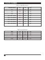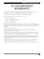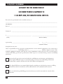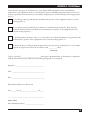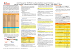
1
JANUARY 1998
MT100A-35-R2
MT100A-449-R2
MT100A-530-R2
T1 CSU/DSU (V35)
T1 CSU/DSU (449)
T1 CSU/DSU (530)
CUSTOMER
SUPPORT
INFORMATION
Order toll-free in the U.S.: Call 877-877-BBOX (outside U.S. call 724-746-5500)
FREE technical support 24 hours a day, 7 days a week: Call 724-746-5500 or fax 724-746-0746
Mailing address: Black Box Corporation, 1000 Park Drive, Lawrence, PA 15055-1018
Web site: www.blackbox.com • E-mail: [email protected]
T1 CSU/DSU
T1 CSU/DSU
Installation and Operation Manual
—————
FEDERAL COMMUNICATIONS COMMISSION
RADIO FREQUENCY INTERFERENCE STATEMENT
This equipment generates, uses and can radiate radio frequency energy and if not
installed and used properly, that is in strict accordance with the manufacturer’s
instructions, may cause interference to radio communication. It has been tested and
found to comply with the limits for a Class A computing device in accordance with the
specifications in Subpart J of Part 15 of FCC rules, which are designed to provide
reasonable protection against such interference when operated in a commercial
environment. Operation of this equipment in a residential area is likely to cause
interference, in which case the user at his own expense will be required to take
whatever measures may be required to correct the interference.
Registration Numbers
FCC Registration Number (unit): ................................GBRUSA-18888-DE-N
UL listing (power supply): ............................................UL3458
DS&G Registration Number .........................................US Safety: E3067
Canadian Use Registration Number : ..........................1596 4190 ACS03–7784
CSA Registration Number (unit): ................................CSA LR3067
CSA Registration Number (power supply): .................CSA LR60602
1
T1 CSU/DSU
TABLE OF CONTENTS
1.0
Specifications ............................................................................................................. 4
2.0
Introduction ............................................................................................................... 6
2.1 General Information .................................................................................................. 6
2.2 Purpose of this Manual ............................................................................................... 6
2.3 Bantam Jacks ............................................................................................................... 6
2.4 Loopback Switches ....................................................................................................... 6
2.4.1 Remote CSU/Aggregate Loopback ................................................................ 7
2.4.2 Remote Channel Loopback ............................................................................. 7
2.4.3 Local Channel Loopback Diagnostic .............................................................. 7
2.4.4 Local Aggregate Loopback .............................................................................. 7
2.5 Network LEDs ............................................................................................................. 7
2.6 Channel LEDs ............................................................................................................. 8
2.7 Rear Panel Controls and Interface Connectors ........................................................ 8
2.8 Channel Interface Connections ................................................................................. 8
2.8.1 Power Connection ............................................................................................ 8
2.8.2 Network Connections ....................................................................................... 8
3.0
Installation .................................................................................................................
3.1 Introduction ..............................................................................................................
3.2 Site Preparation ........................................................................................................
3.3 Installation Procedure ..............................................................................................
3.4 Equipment Cabling ...................................................................................................
3.4.1 Network Cabling .............................................................................................
3.4.2 DTE Channel Cabling ....................................................................................
3.4.3 Power Cabling and Initial Power Up .............................................................
4.0
Operation 11
4.1 Introduction .............................................................................................................. 11
4.1.1 Modify Configuration ..................................................................................... 11
Configuration Worksheet ................................................................................. 12—16
4.1.2 Configuration Tables .............................................................................. 17—19
10
10
10
10
10
10
10
10
Appendix A: FCC Documentation Requirements ..................................................................20
Appendix B: TELCO Affidavit..............................................................................................21
2
T1 CSU/DSU
FIGURES AND TABLES
LIST OF FIGURES
Figure 2-1.
Figure 2-2.
Figure 2-3.
Figure 2-4.
Figure 2-5.
Figure 2-6.
Figure 2-7.
Remote CSU/Aggregate Loopback .............................................................. 7
Remote Channel Loopback ........................................................................... 7
Local Channel Loopback .............................................................................. 7
Local Aggregate Loopback ............................................................................ 7
Rear Panel Connections ................................................................................ 9
Power Connector Pin Out ............................................................................. 9
Network Connector: DB15-to-RJ48 pigtail cable .......................................... 9
LIST OF TABLES
Table 2-1.
Table 4-1.
Table 4-2.
Table 4-3.
Table 4-4.
Table 4-5.
Table 4-6.
V.35 Pin Out ................................................................................................... 8
Configuration Switch 1 Settings .................................................................. 17
Data Rate Selection and DS0 Allocation .................................................... 17
Aggregate Timing Selection ........................................................................ 18
Configuration Switch 3 Settings .................................................................. 18
Output Pulse Selection ................................................................................ 19
Density Selection .......................................................................................... 19
3
T1 CSU/DSU
1.0 SPECIFICATIONS
Configuration
- DIP-switch selectable, readily accessible from the rear panel
Aggregate
- Recommended Cable Requirement: Twisted Shielded-Pair
- Line Rate: 1.544 Mbps +/– 50 bps
- Line Format: AMI or B8ZS
- Framing Format: D4 or ESF(Fe)
- Pulse Characteristics: AT&T 62411 Compliance
- Output Amplitude: 2.4 to 3.3 V peak to base
- Receiver sensitivity: 0 to –26 dB
- Line Buildout (CSU): 0dB, –7.5 dB, –15 dB
- Line Distance (DSX-1 Mode): 0 to 655 Feet
- Line Distance (CSU Mode): 0 to 6000 Feet with 24 AWG
- Interface: RJ45
- Density Monitoring: 1 of 16, 1 of 48, 1 of 64 or None
Internal CSU
- Meets FCC Part 68 requirements
- Meets AT&T Pub 62411
- Local and Remote Loopback Diagnostics
- Type 1 Keep-Alive Signal
Clocking Modes
- Internally Provided
- External From Network (loop)
- External From Channel
4
CHAPTER 1: Specifications
DTE Channels
MT100A–35-R2: CCITT V.35 interface; 34-pin M block (female) connector
MT100A–449-R2: EIA RS-449 interface; DB37(female) connector
MT100A–530-R2: EIA RS-530 interface; DB25 (female) connector
- Density: Alternate DS0 (Fractional T1), Bit 7 stuffing, or None
- Selectable DTE Channel Rates N X 56 kb/s (56, 112, 168, 224, 336, 448, 672, or 1,344)
- Selectable DTE Channel Rates N x 64 kb/s (64, 128, 192, 256, 384, 512, 768, or 1,536.
Compatibility
- AT&T Pub 62411
- AT&T Pub 54019A
- Carrier T1 Service Offerings
- Carrier Fractional T1 Service Offerings
Approvals
- FCC Parts 15 and 68
- UL
- CSA
Diagnostics
- Local Aggregate Loopback
- Remote CSU Loopback
- Local and Remote Channel Loopbacks
- Tx/Rx Monitor Jacks and Network In and Network Out Jacks
- Test LED lit when active
Front Panel Network Indicators
- Loss Of Signal (LOS)
- Bipolar Violations (BPV)
- Synchronization
- Red Alarm
- Yellow Alarm
- Test
5
T1 CSU/DSU
Front Panel DTE Channel Indicators
- Transmit Data (TD)
- Receive Data (RD)
- Request To Send (RTS)
- Receive Line Signal Detect (RLSD)
Standalone Unit
- Size: 1.5"H x 7.25"W x 10.5"D
(3.8 x 18.4 x 26.7 cm)
- Weight: 2 lb. (0.9 kg)
- Power: External Wall Mount Power Supply
Environmental
- Temperature: 32° to 122°F (0° to 50°C)
- Storage Temperature: –4° to 176°F (–20° to 80° C)
- Relative Humidity: 0 to 95% noncondensing
- Maximum Altitude: 15,000 ft. (4572m)
Mean Time Between Failure (Estimated)
– 40,000 hours
6
CHAPTER 2: Introduction
2.0 INTRODUCTION
2.1 General Information
The T1 CSU/DSU product line is a high speed T1 format processor with one of three interfaces for
the DTE channel: CCITT V.35; RS-449; RS-530. It is capable of processing data at speeds from 56kb/s
to 1.536Mb/s, depending upon the format and density requirements of the application. It provides
all the framing and density requirements for data transmission across predefined network facilities,
such as ACCUNET.
The T1 CSU/DSU, because of its unique design, is able to accept timing information from any clock.
Timing information may be derived from the receive data, an external DTE, or from the internal crystal
oscillator. The T1 CSU/DSU has a series of selectable diagnostics that allow the user to quickly and
accurately troubleshoot the T1 CSU/DSU and the associated network.
The T1 CSU/DSU has a built in CSU which complies with AT&T Publication 62411. This allows the
user to attach the T1 CSU/DSU directly to the T1 Circuit. This CSU can be enabled or disabled with
a simple switch setting so that the unit can act as a DSU or as a DSU/CSU. It can also be used as a high
speed line driver to extend high speed data circuits up to 6,000 feet over shielded twisted-pair cable.
2.2 Purpose
The purpose of this document is to present to the reader the information necessary to completely
understand the operation, installation, and diagnostic procedures associated with the T1 CSU/DSU.
Chapter 1 provides the technical specifications for the T1 CSU/DSU. This chapter presents a brief
description of the unit, and its features and applications. Chapter 3 gives you the installation and initial
power-up procedures. Chapter 4 explains the interactive programming procedures associated with the
T1 CSU/DSU, and Chapter 5 gives a detailed explanation of the T1 CSU/DSU diagnostic procedures.
The T1 CSU/DSU contains all the controls and indicators necessary to configure, monitor, diagnose,
and operate the system. The front panel contains four bantam jack receptacles for network data
monitoring and test signal injection, loopback selection switches for aggregate and channel loopbacks,
and a series of LEDs that reflect the status of both the network and the DTE channel.
2.3 Bantam Jacks
The Bantam Jacks, located on the T1 CSU/DSU front panel, provide easy access to both monitor
the T1 service without interrupting the transmission of information or to inject a test signal to
exercise the T1 circuit.
To monitor the T1 service, connect a test set to the T1 CSU/DSU via the Transmit Monitor (NET TX
MON) Bantam Jack and the Receive Monitor (NET RX MON) Bantam Jack. This allows the user to
monitor the T1 service without interrupting the information flow.
To inject and receive a test signal across the T1 transmission facility, connect the test set into the IN
(NET TX IN) and OUT (NET RX OUT) Bantam Jacks. Then, place the T1 CSU/DSU in Remote
Channel Loopback. In this configuration the operator can inject a known signal and receive it back
via the network for testing purposes. This is an interruptive test. Data integrity can not be guaranteed
during this test.
7
T1 CSU/DSU
2.4 Loopback Switches
There are two Loopbacks switches on the front panel of the of the T1 CSU/DSU. Both switches allow the
user to test individual sections of data transmission path. This ability to test these individual paths allows
the user to isolate, diagnose, and then perform corrective action to resolve data transmission problems
in the network.
2.4.1 REMOTE CSU/AGGREGATE LOOPBACK
The REMOTE CSU/AGGREGATE LOOPBACK (see Figure 2-1) test lets you verify the logic from the
local interface through the remote aggregate and back to the local channel interface. To select this test,
position the AGGREGATE LOOPBACK switch in the REMOTE position. When complete, return this
switch to the center position.
TX
CHANNEL
Test
Equip.
TX
RX
RX
TX
CHANNEL
RX
TX
RX
Figure 2-1. Remote CSU/Aggregate Loopback.
2.4.2 REMOTE CHANNEL LOOPBACK
To verify the remote unit’s channel logic from the local unit (Figure 2-2), select the remote position of
the AGGREGATE LOOPBACK switch. When complete, reposition this switch to the center position.
TX
CHANNEL
Test
Equip.
TX
RX
RX
TX
CHANNEL
RX
TX
RX
Figure 2-2. Remote Channel Loopback.
2.4.3 LOCAL CHANNEL LOOPBACK DIAGNOSTIC
Local Channel Loopback Diagnostic (Figure 2-3) enables you to verify the channel interface. To run this
test, position the CHANNEL LOOPBACK SWITCH in the LOCAL position. When complete, reposition
the switch to the center position.
TX
Test
Equip.
CHANNEL
TX
RX
RX
TX
CHANNEL
RX
Figure 2-3. Local Channel Loopback.
8
RX
TX
CHAPTER 2: Introduction
2.4.4 LOCAL AGGREGATE LOOPBACK
The LOCAL AGGREGATE LOOPBACK diagnostic (Figure 2-4) enables the user to verify the T1
CSU/DSU logic from the channel interface, through the aggregate, and return to the channel interface.
To select this test, position the AGGREGATE LOOPBACK switch in the LOCAL position. When
complete, reposition the switch to the center position.
TX
Test
Equip.
CHANNEL
TX
RX
RX
TX
CHANNEL
RX
TX
RX
Figure 2-4. Local Aggregate Loopback.
2.5 NETWORK LEDs
Six LEDs indicate network function of the unit: Loss Of Signal (LOS), Bipolar Violations (BPV),
RED and YELLOW alarms, SYNC, and TEST.
LOS LED — when illuminated, indicates the lack of sufficient signal pulses(marks) at the network receiver. The LED
is illuminated when more than 175 consecutive zeros are received and is extinguished when the next mark is detected.
Bipolar Violations LED — when illuminated, indicates that a pulse was received that is of the same polarity as
the preceding pulse(excluding B8ZS codewords), thus violating the Alternative Mark Inversion Rule.
RED ALARM LED — illuminated when the receiver has lost frame synchronization for 2 to 2.5 seconds.
The LED is extinguished when FRAME SYNC has been acquired for at least eight consecutive seconds.
YELLOW ALARM LED — illuminated while a YELLOW ALARM indication is being received from the remote unit.
The remote unit will transmit a YELLOW ALARM indication while in the RED ALARM state. While operating in D4 framing,
the YELLOW ALARM condition is transmitted by forcing bit 2 of every DS0 to a zero state. In ESF framing mode, the YELLOW
ALARM condition is a pattern embedded in the framing overhead.
SYNC LED — lit when the local unit is in SYNC with the remote unit. It is extinguished when
synchronization is lost. Frame sync criteria is the receipt of 10 consecutive F bits. Sync loss criteria
is receipt of 2 of 4 consecutive frame word errors.
TEST LED — lit whenever the unit is in a selected diagnostic mode or test ,or while the unit is sending
diagnostic patterns.
2.6 CHANNEL LEDs
The four LEDs below the CHANNEL heading represent the status of the channel side of the unit.
The Channel TD (green) LED is illuminated when the channel is transmitting a space. The Channel RD
(green) LED is illuminated when the channel is receiving a space. The Request to Send (RTS) LED is
illuminated when the Request to Send function is active. The Channel RLSD (green) LED is illuminated
when the channel’s Receive Line Signal Detect function is active.
2.7 REAR PANEL CONTROLS AND INTERFACE CONNECTORS
The rear panel (Fig. 2-5) provides access to the physical interfaces necessary to connect the unit to a
network. Depending on the model, there is one of the following female connectors on the rear panel
for the DTE interface: 34-pin M block (V.35); DB37 (RS-449); or DB25 (RS-530). There is also a five-pin
DIN power connector for applying logic power (–5 and +/–12 VDC) to the unit. There are two DIP
switches—Switch 1 and Switch 3—along with the LBO switch (Switch 2).
9
T1 CSU/DSU
NOTE
When operating as a channel service unit (CSU), the setting of the Line Build Out function is
dictated by the carrier and must be set as the carrier specifies. Otherwise, the LBO Switch must
be set to zero (0) dB position.
2.8 CHANNEL INTERFACE CONNECTIONS
T1 CSU/DSU is configured for DTE connection with one of these three interfaces: V.35; RS-449; or RS530 (female connectors). Below are the pin-outs (male connectors) for these interfaces.
V.35 Pin Out (34-pin male connector)
PIN
FUNCTION
A . . . . . . . . . . . . . . . . . . . . . . .GROUND
D . . . . . . . . . . . . . . . . . . . . . . . . .CTS
E . . . . . . . . . . . . . . . . . . . . . . . . .DSR
F . . . . . . . . . . . . . . . . . . . . . . . . .DCD
P . . . . . . . . . . . . . . . . . . . . . . . . .SD(A)
R . . . . . . . . . . . . . . . . . . . . . . . .RD(A)
S . . . . . . . . . . . . . . . . . . . . . . . . .SD(B)
PIN
FUNCTION
T . . . . . . . . . . . . . . . . . . . . . . .RD(B)
U . . . . . . . . . . . . . . . . . . . . . . . .TT(A)
V . . . . . . . . . . . . . . . . . . . . . . .RT(A)
W . . . . . . . . . . . . . . . . . . . . . . .TT(B)
X . . . . . . . . . . . . . . . . . . . . . . .RT(B)
Y . . . . . . . . . . . . . . . . . . . . . . . .ST(A)
AA . . . . . . . . . . . . . . . . . . . . . . .ST(B)
RS-449 Pin Out (DB37 male connector)
1 ..........................................Shield
2 ..............................Signal Rate Indicator
3 ..............................................—
4 ....................................Send Data (A)
5 ..................................Send Timing (A)
6 ..................................Receive Data (A)
7................................Request ToSend (A)
8 ................................Receive Timing (A)
9..................................Clear To Send (A)
10 ..................................Local Loopback
11....................................Data Mode(A)
12 ..............................Terminal Ready (A)
13 ..............................Receiver Ready (A)
14 ................................Remote Loopback
15 ....................................Incoming Call
16 ................................Select Frequency
17 ..............................Terminal Timing (A)
18 ......................................Test Mode
19....................................Signal Ground
20
21
22
23
24
25
26
27
28
29
30
31
32
33
34
35
36
37
. . . . . . . . . . . . . . . .Receive Common
. . . . . . . . . . . . . . . . . . . . . . .—
. . . . . . . . . . . . . . . . . .Send Data (B)
. . . . . . . . . . . . . . . . .Send Timing (B)
. . . . . . . . . . . . . . . . .Receive Data (B)
. . . . . . . . . . . . . . .Request to Send (B)
. . . . . . . . . . . . . . . .Receive Timing (B)
. . . . . . . . . . . . . . . . .Clear to Send (B)
. . . . . . . . . . . . . . . .Terminal in Service
. . . . . . . . . . . . . . . . . . .Data Mode
. . . . . . . . . . . . . . . .Terminal Ready (B)
. . . . . . . . . . . . . . . .Receiver Ready (B)
. . . . . . . . . . . . . . . . . .Select Standby
. . . . . . . . . . . . . . . . . .Signal Quality
. . . . . . . . . . . . . . . . . . .New Signal
. . . . . . . . . . . . . . . .Terminal Timing (B)
. . . . . . . . . . . . . . . . .Standby/Indicator
. . . . . . . . . . . . . . . . . .Send Common
RS-530 Pin Out (DB25 male connector)
1 . . . . . . . . . . . . . . . . . . . . . . . .Shield (A)
2 . . . . . . . . . . . . . . . . . . .Transmitted Data (A)
3 . . . . . . . . . . . . . . . . . . . .Received Data (A)
4 . . . . . . . . . . . . . . . . . . . .Request to Send (A)
5 . . . . . . . . . . . . . . . . . . . . .Clear to Send (A)
6 . . . . . . . . . . . . . . . . . . . . . .DCE Ready (A)
7 . . . . . . . . . . . . . . . . . . . . . .Signal Ground
8 . . . . . . . . . . . . . .Received Line Signal Detector (A)
9 . . . . . . . . . . .Receiver Signal Element Timing–DCE (B)
10 . . . . . . . . . . . . . .Received Line Signal Detector (B)
11 . . . . . . . . . .Transmitter Signal Element Timing–DTE (B)
12 . . . . . . . . .Transmitter Signal Element Timing–DCE (B)
13 . . . . . . . . . . . . . . . . . . . .Clear to Send (B)
14 ......................................Transmitted Data (B)
15 ..........................Transmitter Signal Element DCE (A)
16 ........................................Received Data (B)
17 ......................Receiver Signal Element Timing DCE (A)
18 ..........................................Local Loopback
19 ..........................................Request to Send
20 ..........................................DTE Ready (A)
21 ........................................Remote Loopback
22 ..........................................DCE Ready (B)
22 ..........................................DCE Ready (B)
23 ..........................................DTE Ready (B)
24 ....................Transmitter Signal Element Timing DTE (A)
25 ..............................................Test Mode
2.8.1 POWER CONNECTION
The power connector (female) is on the rear panel. The male connector of the DC power supply plugs
into this female connector. Fig. 2-6 shows the pinout of the 5-pin DIN connecter.
2.8.2 NETWORK CONNECTION
The Network connector is an RJ48C modular connector with an RJ48C-to-DB15 pigtail cable (not
supplied). Refer to Figure 2-7.
10
CHAPTER 2: Introduction
POWER
V.35, RS-449, or RS-530 channel
NETWORK
SW 1
LBO
0 –7.5 –15
SW 3
SW 2
SEE BASE FOR SWITCH SETTING INFORMATION
Figure 2-5. Rear Panel Connections.
VM Series Regaulated Table Top Power Supply
Pin 1 = Common
Pin 2 = N/C
Pin 3 = +5V
Pin 4 = –12V
Pin 5 = +12V
3
1
5
4
2
Figure 2-6. Power Connector Pin Out.
DB15
RJ48C
Signal
1
5
TX TIP
3
2
RX TIP
9
4
TX RING
11
1
RX RING
2 and 7
7 and 8
GND
8
15
1
9
DB15 Male
Connector
87654321
8-Pin
RJ48C Connector
Figure 2-7. Network Connector: DB15-to-RJ48 pigtail cable.
11
T1 CSU/DSU
3.0 INSTALLATION
3.1 INTRODUCTION
This chapter has the information necessary to plan, perform and verify the mechanical and electrical
installation of the T1 CSU/DSU. Before installing the T1 CSU/DSU, read and completely understand
the information presented here.
3.2 SITE PREPARATION
The T1 CSU/DSU should be installed within 7 feet of a grounded AC outlet furnishing 115/230VAC.
The location should be clean, well lighted, and conform to the standards for computer equipment
installations. Allow a 36 inch clearance for both the front and back of the unit for access during
operation and maintenance. When connecting the interface cables, allow 4 feet of slack in the cables
so that you can move the unit to perform service without disconnecting the cables.
3.3 INSTALLATION PROCEDURE
Before installing the T1 CSU/DSU system, carefully read and understand the total installation
procedure.
3.3.1 UNPACKING
Although we take great care to insure that the T1 CSU/DSU is properly packaged so that it will not
be damaged during transit, it is the customer’s responsibility to verify that the unit arrives undamaged.
Before unpacking the T1 CSU/DSU, read the following:
1. Carefully remove all packing material from the T1 CSU/DSU.
2. Inspect the equipment for damage that may have occurred during shipment. If any damage is noted,
contact the shipping agent and the manufacturer.
NOTE
The T1 CSU/DSU shipping carton is designed to ensure that the device arrives at the
customer’s location undamaged. If it ever becomes necessary to move the T1 CSU/DSU
to another location, it is advisable to save the shipping carton for such use.
3.4 EQUIPMENT CABLING
3.4.1 NETWORK CABLING
The Network connector is an RJ48C modular type connector with an optional RJ48C-to-DB15 pigtail
cable (not supplied). Depending upon the configuration of the network, either connect the network
line cable directly into the unit or first connect the RJ48C-to-DB15 pigtail cable into the unit and then
connect the network line cable to the DB15 end of the pigtail cable.
3.4.2 DTE CHANNEL CABLING
The T1 CSU/DSU is configured at the factory to be connected via an industry standard channel
interface using either a V.35, RS-449, or RS-530 cable. When the DTE interface cable is in position and
seated, secure it with the two jack screws. For information about DTE interface pinouts, see Section 2.8,
Channel Interface Connections on page 8.
12
CHAPTER 3: Installation
3.4.3 POWER CABLING AND INITIAL POWER UP
NOTE
Before connecting the power cable to the T1 CSU/DSU, ensure that the unit is properly
configured and all interface cables are connected and seated.
Power to the T1 CSU/DSU is supplied by a separate DC Power Supply. Insert the power supply male DIN
connector into the female DIN connector at the rear of the unit. Insert the power cable male connector
into a grounded AC power receptacle. At this time power is applied to the T1 CSU/DSU.
13
T1 CSU/DSU
4.0 OPERATION
4.1 INTRODUCTION
The T1 CSU/DSU is controlled by a series of simple switch settings that the operator can select by
accessing Switches one, two, and three at the rear of the unit.
4.1.1 MODIFY CONFIGURATION
To configure a new T1 CSU/DSU Series unit or modify the configuration of an existing T1 CSU/DSU
Series unit, first determine the correct information by reviewing following worksheet. This worksheet
should be copied and annotated so that when completed it can be saved for future reference.
Before completing the worksheet, the user should have a complete understanding of the application
being served by the T1 CSU/DSU format processor.
14
CHAPTER 4: Operation
Configuration Worksheet
CUSTOMER NAME:
_______________________________________________________
DATE:
_______________________________________________________
CUSTOMER LOCATION:
_______________________________________________________
CONFIGURATION:
_______________________________________________________
SWITCH ONE SETTINGS
1. DATA RATE SELECTION (SEE TABLE 3-2) ...................................S1-1
S1-2
S1-3
2. DTE Channel Multiples .....................................................................N X 56 kb/s: S1-4: ON
N X 64 kb/s: S1-4: OFF
Selectable N X 56 Rates:
8, 16, 24, 32, 40, 48, 56, 64, 112, 168, 192, 224, 280, 320, 336, 448, 560, 672,
840, 960, 1120, and 1344kbps.
NOTE
For specific speed selection information refer to Table 4-2
Selectable N X 64 Rates:
8,16, 24, 32, 40, 48, 64,128,192, 256, 320, 384, 512, 640, 768, 960,1280,
and 1536kb/s.
NOTE
For specific speed selection information refer to Table 3-2.
15
T1 CSU/DSU
3. CHANNEL SEND TIMING:
A.
LOOP 1 (Terminal Timing) ........................................S1-5: ON
B.
LOOP 2 (Send Timing) ...............................................S1-5: OFF
4. CHANNEL TIMING:
A.
NORMAL .......................................................................S1-6: ON
B.
INVERTED ....................................................................S1-6: OFF
5. CHANNEL DATA:
A.
NORMAL ......................................................................S1-7: 0N
B.
INVERTED ....................................................................S1-7: OFF
6. REQUEST TO SEND CONTROL
A.
ALWAYS ON ..................................................................S1-8: ON
B.
CONTROLLED .............................................................S1-8: OFF
7. AGGREGATE TIMING SELECTION:
A. INTERNAL (MASTER) CRYSTAL TIMING........................S1-9:
ON
S1-1 0: ON
B. LOOP (SLAVE) TIMING......................................................S1-9:
OFF
S1-1 0: ON
C. EXTERNAL CHANNEL TIMING (NOTE 1 ).....................S1-9:
ON
S1-1 0: OFF
D. INTERNAL (MASTER) CRYSTAL TIMING .......................S1-9:
OFF
S1-10: OFF
NOTE
If the EXTERNAL CHANNEL TIMING
selection is made, then the associated
CHANNEL SEND TIMING must be set to Loop
1 Timing. When operating in this mode, the
DCE provides the network timing.
16
CHAPTER 4: Operation
SWITCH TWO SETTINGS
1. LBO SETTlNG (Active only in the CSU mode of operation. When operating in the DSX-1 mode, the
LBO switch must be in the zero [0] dB position.). Position the LBO switch as directed by the carrier:
A.
–1 5dB
B.
–7.5dB
C.
0dB
SWITCH THREE SETTINGS
1. NETWORK FRAMING:
A. D4: .......................................................................................S3-1: ON
B. ESF(Fe): ................................................................................S3-1: OFF
2. NETWORK LINE CODE:
A. AMI: .......................................................................................S3-2: ON
B. B8ZS: ......................................................................................S3-2: OFF
3. NETWORK INTERFACE:
A. CSU: .......................................................................................S3-3: ON
S3-4: OFF
S3-5: ON
NOTE
If the CSU Mode of operation is
selected, then the LBO switch must
be set as defined by the carrier. Refer
to Switch 2 setting information
presented below. If the CSU Mode is
selected, then all the DSX-1
selections are invalid. If the unit is
not to be operated as a CSU but in
the DSX-1 mode, then the TRANSMIT
OUTPUT PULSE must be defined.
17
T1 CSU/DSU
In making the following 5 selections, the operator defines the mode of operation as DSX1 and also
specifies the proper transmit output pulse.
4. TRANSMIT OUTPUT PULSE: (DSX-1 Mode Only. If any of the output pulse selections are made,
then the CSU selection is invalid. If a DSX-1 Mode is selected, verify that the LBO Switch is in the
O position.) The TRANSMIT OUTPUT PULSE selection is determined by the distance between
the unit and the external CSU.
A. 000 – 133 FT ..........................................................................S3-3: OFF
S3-4: OFF
S3-5: ON
B. 133 – 266 FT ..........................................................................S3-3: ON
S3-4: ON
S3-5: OFF
C. 266 – 399 FT ..........................................................................S3-3: OFF
S3-4: ON
S3-5: OFF
D. 399 – 533 FT..........................................................................S3-3: ON
S3-4: OFF
S3-5: OFF
E. 533 – 655 FT ..........................................................................S3-3: OFF
S3-4: OFF
S3-5: OFF
5. DENSITY MONITOR:
A.
1 IN 16 ...........................................................................S3-6: OFF
S3-7: ON
S3-8: ON
B.
1 IN 32 ..........................................................................S3-6: OFF
S3-7: OFF
S3-8: ON
C.
1 IN 48 ..........................................................................S3-6: OFF
S3-7: ON
S3-8: OFF
18
CHAPTER 4: Operation
D.
1 IN 64 ...........................................................................S3-6: OFF
S3-7: OFF
S3-8: OFF
E.
NONE ...........................................................................S3-6: ON
S3-7: N/A
S3-8: N/A
6. ZERO BYTE SUPPRESSION
A.
INHIBIT: .......................................................................S3-9: ON
B.
ACTIVE: ........................................................................S3-9: OFF
7. DS0 MAPPING
A. CONTIGUOUS: ...................................................................S3-10: ON
B. ALTERNATE: ........................................................................S3-10: OFF
NOTE
Refer to Table 4-2 for the information pertaining to the
DSOs used with either contiguous or alternate DS0 mapping.
When the configuration worksheet is complete and verified, you can
configure the unit by simply setting the switches on the rear panel as defined
on the worksheet.
19
T1 CSU/DSUT1 CSU/DSUNAME
4.1.2 CONFIGURATIONS TABLES
When the user becomes proficient with the configuration procedures of the T1 CSU/DSU Series unit, it
may easier and simpler to use the configuration tables presented below and also available on the bottom
of the device to quickly configure the T1 CSU/DSU Series unit.
Table 4-1. Configuration Switch 1 Settings.
POSTION
DESCRIPTION
ON
OFF
1
DATA RATE SELECTION
SEE TABLE 4-2
2
DATA RATE SELECTION
SEE TABLE 4-2
3
DATA RATE SELECTION
SEE TABLE 4-2
4
RATE MULTIPLE
N x 56K
N x 64K
5
CHANNEL SEND TIMING
LOOP 1
LOOP 2
6
CHANNEL TIMING
NORMAL
INVERT
7
CHANNEL DATA
NORMAL
INVERT
8
RTS
ON
CONTROLLED
9
AGGREGATE TIMING SELECTION
SEE TABLE 4-3
10
AGGREGATE TIMING SELECTION
SEE TABLE 4-3
Table 4-2. Data Rate Selection and DS0 Allocation.
S14 ON
20
DATA RATE(Kbps)
S14 OFF
S1-1
S1-2
S1-3
DSO’S USED
S3-10
S3-10
ON
OFF
56
64
ON
ON
ON
1
1-2
112
128
OFF
ON
ON
1-2
14
168
192
ON
OFF
ON
1-3
1-6
224
256
OFF
OFF
ON
14
1-8
336
384
ON
ON
OFF
1-6
1-12
448
512
OFF
ON
OFF
1-8
1-16
672
768
ON
OFF
OFF
1-12
1-24
1344
1536
OFF
OFF
OFF
1-24
N/A
CHAPTER 4: Operation
Table 4-3. Aggregate Timing Selection.
TRANSMIT TIMING REFERENCE
S1–9
S1–10
INTERNAL (MASTER) CRYSTAL TIMING
ON
ON
LOOP (SLAVE) TIMING
OFF
ON
EXTERNAL CHANNEL TIMING
ON
OFF
INTERNAL (MASTER) CRYSTEL TIMlNG
OFF
OFF
Table 4-4. Configuration Switch 3 Settings.
POSITION
DESCRIPTION
ON
OFF
1
FRAMING FORMAT
D4
ESF (Fe)
2
ENCODING FORMAT
AMI
B8ZS
3
OUTPUT PULSE
SEE TABLE 4-5
4
OUTPUT PULSE
SEE TABLE 4-5
5
OUTPUT PULSE
SEE TABLE 4-5
6
DENSlTY SELECTION
SEE TABLE 4-6
7
DENSlTY SELECTION
SEE TABLE 4-6
8
DENSlTY SELECTION
SEE TABLE 4-6
9
ZERO BYTE SUPPRESSION
INHIBIT
ACTIVE
10
DS0 MAPPING
CONTIGUOUS
ALTERNATIVE
21
T1 CSU/DSUT1 CSU/DSUNAME
Table 4-5. Output Pulse Selection.
LINE LENGTH SELECTED
S3-3
S3-4
S3-5
N/A
ON
ON
ON
N/A
OFF
ON
ON
CSU
ON
OFF
ON
DSX–1 000 – 133 FEET
OFF
OFF
ON
DSX–1 133 – 266 FEET
ON
ON
OFF
DSX–1 266 – 399 FEET
OFF
ON
OFF
DSX–1 399 – 533 FEET
ON
OFF
OFF
DSX–1 533 – 655 FEET
OFF
OFF
OFF
Table 4-6. Density Selection.
22
RATIO
S3-6
S3-7
S3-8
1 IN 16
OFF
ON
ON
1 IN 32
OFF
OFF
ON
1 IN 48
OFF
ON
OFF
1 IN 64
OFF
OFF
OFF
NONE
ON
N/A
N/AQ
APPENDIX A: FCC Documentation Requirements
FCC DOCUMENTATION
REQUIREMENTS
The following information is required by FCC Part 68 Rules which inform the user of his rights
and obligations in connecting this equipment to he network and in ordering service.
This equipment complies with Part 68 of FCC Rules. Please note the following:
1. When you order service, the telephone company needs to know:
a. The Facility Interface Code:
04DU-B
(1.544 MB D4 framing format)
04DU9-C (1.544 MB ESF format)
b. The Service Order Code: 6.0F
A signal power affidavit will be required to guarantee encoded analog content and billing protection
unless this unit is used in combination with an XD type device or no encoded analog signals and billing
information are transmitted. A sample of the affidavit is attached. For most uses, the second box is
appropriate.
c. The USOC Jack Required: RJ48C
In addition, if requested, please inform the telephone company of the make, model and FCC
Registration Number, which are on the label.
2. Your telephone company may make changes in its facilities, equipment, operations or procedures
that could affect the proper functioning of your equipment. If they do, you will be notified in advance
to give you an opportunity to maintain uninterrupted telephone service.
3. If your telephone equipment causes harm to the telephone network, the telephone company may
discontinue your service temporarily. If possible, they will notify you in advance, but if advance notice
is not practical, you will be notified as soon as possible. You will be informed of your right to file a
complaint with the FCC.
4. If you experience trouble with the telephone equipment, please contact us for information on
obtaining service or repairs. Repairs should be performed by us or our authorized agent.
5. You are required to notify the telephone company when this unit is disconnected from the network.
23
T1 CSU/DSUT1 CSU/DSUNAME
AFFIDAVIT FOR THE CONNECTION OF
CUSTOMER PREMISES EQUIPMENT TO
1.544 MBPS AND/OR SUBRATE DIGITAL SERVICES.
For work to be performed in the certified territory of
___________________________________________________________________________________________
(TELCO Name)
State of: ___________________________________________________________________________________
County of: ________________________________________________________________________________
I ___________________________________________, ____________________________________________
(name)
(Business Address)
representing ______________________________________________(
)______—__________________
(Telephone Number)
being duly sworn, state:
I have responsibility for the operation and maintenance of the terminal equipment to be connected to
____________________ 1.544 Mbps and/or _____________________ Subrate digital services. The
terminal equipment complies with Part 68 of the Commission’s rules except for the encoded analog
content and billing protection specifications. With respect to encoded analog content and billing
protection:
I attest that all operations associated with the establishment, maintenance and adjustment
of the digital CPE with respect to encoded analog content ant encoded billing information
continuously complies with Part 68 of the FCC’s Rules and Regulations.
The digital CPE does not transmit digital signals containing encoded analog content or billing
information which is intended to be decoded within the telecommunications network.
The encoded analog and billing protection is factory set and is not under the control of the
customer.
24
APPENDIX B: TELCO Affidavit
I attest that the operator(s)/maintainer(s) of the digital CPE responsible for the establishment,
maintenance and adjustment of the encoded analog content and billing information has (have) been
trained to perform these functions by successfully completing one of the following (Check appropriate
one(s))
a. A training course provided by the manufacturer/grantee of the equipment used to encode
analog signals; or
b. A training course provided by the customer or authorized representative, using training
materials and instructions provided by the manufacturer/grantee of the equipment used to
encode analog signals; or
c. An independent training course (e.g., trade school or technical institution) recognized by the
manufacturer/grantee of the equipment used to encode analog signals; or
d. In lieu of the preceding training requirements, the operator(s)/maintainer(s) is (are) under
control of a supervisor trained in accordance with __________ above.
(circle one)
I agree to provide_________________________with proper documentation to demonstrate compliance
with the information as provided in the preceding paragraph, if so requested.
Signature ____________________________________
Title ________________________________________
Date ________________________________________
Subscribed and Sworn to before me
this _______day of_____________________,19_____
_____________________________________________
Notary Public
My commission expires: _______________________
25
© Copyright 1998. Black Box Corporation. All rights reserved.
1000 Park Drive
•
Lawrence, PA 15055-1018
•
724-746-5500
•
Fax 724-746-0746