1
XL-VCQ102SB
4-band VDSL CPE/Slave bridge
User’s Guide
VDSL Point to Point Solution
The VDSL (Very High Data Rate DSL) networking solution delivers cost-effective, high-performance broadband access to multiunit
buildings (hotels, apartment, and multi-tenant unit office buildings) and enterprise campus environments such as manufacturing,
educational campuses, and medical facilities. VDSL technology dramatically extends Ethernet over existing Category 1/2/3 wiring at
speeds 10Mbps (full duplex) and distances up to 1200 meters. The VDSL technology delivers broadband service on the same lines as
Plain Old Telephone Service (POTS), digital telephone, and ISDN system. In addition, VDSL supports modes compatible with
asymmetric digital subscriber line (ADSL), allowing service providers to provision VDSL to buildings where broadband services already
exist.
The VDSL solution includes VDSL IP DSLAM (VDSL switches), and VDSL Modem for Customer Premise Equipment (CPE) device.
The VDSL solution delivers everything needed to quickly deploy an Ethernet-based network with the performance required to deliver
high-speed Internet access at much greater distances and drive services like IP telephony and audio/video streaming. With this
technology, a broad range of customers can benefit from lower operating costs and rapid deployment. The VDSL solution provides
multicast, Layer 2 quality of service (QOS), Link Aggregation (LACP) dynamic trunking group, security, GVRP, IGMP for VOD (Video on
demand) and SNMP RMON management and Web-based Switch network management.
The VDSL IP DSLAM is a bridge between external Internet backbone through a router for IP sharing and the building 110D telephone
rack or telephone box. It utilizes the available telephone wire to enable high-speed Internet access to building residents.
The IP DSLAM uses the phone line networking technology endorsed by the VDSL, and the IP DSLAM utilizes the already existing
telephone wire to deliver 10 Mbps Internet access on each RJ-11 port.
This gives users a low-cost, end-to-end solution and eliminates the need to train installation teams on multiple systems.
1
Foreword
The VDSL Modem is an Ethernet to VDSL adapter that enables high speed internet access to building residents, campuses students and
hotel guests by connecting Ehternet equipped computers, set-top box or any internet access device to the existing telephone wires.
The VDSL Modem uses the phoneline networking technology endorsed by the VDSL, an association of industry-leading companies for
in – networking focus on the existing telephone wire.
The Modem utilize the already existing telephone wire to deliver 10Mbps internet access with no interference on the existing telephone
service. It allows user to make calls while access the internet on the same wire simultaneously. It even allows staying connected 24
hours on internet connections, thus, eliminating dial up prior to internet access.
The Modem is simple to install and use. One RJ-45 Ethernet connects to a Router, Ethernet Switch or to LAN card. The RJ11 ports
available to connect to any existing modular phone jack.
There are two RJ-11 jack on the Modem to provide a phone extensions.
No software installation makes the Modem highly compatible with different operating system ( Windows, Linux, Apple….etc).
2
Contents
1.Unpacking Information
Check List --------------------------------------------------------4
2.Installation
Hardware Installation------------------------------------------5
Pre-Installation Requirements ------------------------------5
General Rules---------------------------------------------------6
Connecting the Modem ---------------------------------------6
Connecting the RJ-11/RJ-45 Ports ------------------------7
3.Hardware Description
Front Indicators -------------------------------------------------9
Rear Connectors -----------------------------------------------11
Power On---------------------------------------------------------11
4.Applications
Application for Home networking ---------------------------12
Appendix A Cable Requirement ----------------------------13
Appendix B Product Specifications -----------------------15
Appendix C Trouble Shooting-------------------------------17
Appendix D Link Recover Procedures--------------------22
Appendix E Accessories-Bracket---------------------------23
Appendix F Compliant and Safety Information-------- 24
FCC/CE Warning--------------------------------------------------26
Warranty------------------------------------------------------------ 27
3
1.Unpacking Information
Check List
Carefully unpack the package and check its contents against the checklist.
Package Contents
•
•
•
•
•
•
Ethernet to VDSL Modem
Four plastic feet
User Manual
AC to DC Power Adapter
RJ-45 cable
RJ-11 cable
Please inform your dealer immediately for any missing, or damaged parts.
If possible, retain the carton, including the original packing materials,
Use them to repack the unit in case there is a need to return for repair.
4
2.Installing the Modem
Hardware Installation
This chapter describes how to install the Modem and establishes network connections. You may install the Modem on any level surface (e.q, a
table or shelf). However, please take note of the following minimum site requirements before you begin. Stick the 4 plastic feet at the bottom.
Pre-installation Requirements
Before you start actual hardware installation, make sure you can provide the right operating environment, including power
requirements, sufficient physical space, and proximity to other network devices that are to be connected.
Verify the following installation requirement:
• Power requirements: DC5V/1A or above.
• The Modem should be located in a cool dry place, with at least 10cm/4in of space at the front and back for ventilation.
• Place the Modem out of direct sunlight, and away from heat sources or areas with a high amount of electromagnetic
interference.
• Check if network cables and connectors needed for installation are available.
5
General Rules
Before making any connections to the Modem, note the following rules:
• Ethernet Port (RJ-45)
All network connections to the Modem Ethernet port must be made using Category 5 UTP for 100Mbps; Category 3,4 UTP for
10Mbps
No more than 100 meters of cabling may be use between the MUX or HUB and an end node.
• VDSL Port (RJ-11)
All Home network connections to the RJ-11Port made using 24~26 Gauge phone wiring.
• We do not recommend using 28 Gauge or above phone line.
Connecting the Modem
The Modem has one Ethernet port which support connection to Ethernet operation. The devices attached to these ports must support
auto-negotiation or 10Base-T or 100Base-TX unless they will always operate at half duplex.
Use any of the Ethernet ports to connect to devices such as HUB, IP DSLAM, bridge or router. You can also connect to another
compatible Modem to an RJ-45 port on the other device.
The RJ11 Line port are use to connect to the wall RJ-11 modular socket which is connect to VDSL Switch or VDSL Modem CO side
The RJ11 Phone port of the Modem can connected to a telephone and a computer sharing one telephone wire for making calls and
accessing the internet at the same time.
6
Connecting the RJ-11/RJ-45 Ports
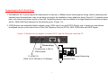
1.The Modem’s RJ-11 ports support the transmission of data up to 10Mbps across existing phone wiring, without interfering with
standard voice transmissions, easy-to-use does not require the installation of any additional wiring. Every RJ-11 modular phone
jack in the home can become a port on the LAN. Networking devices can be installed on a single telephone wire that can span
within 1.9KM (6000 feet) between the two farthest points. (Figure 1.0).
2. VDSL Modem has embedded Splitter between every VDSL side (Line) and POTS (Phone) side. It permit you can delivers
broadband service on the same lines as Plain Old Telephone Service (POTS), PBX, ISDN traffic and VDSL Signal.
Figure 1.0 Modem use as adapter to connect RJ-11 and the LAN card inside the PC
Phone wiring
To telephone or FAX or
ISDN modem
To VDSL CO
(VDSL CO IP DSLAM or CO Modem)
7
10/100 Fast Ethernet Networking
Interface Card
3.The RJ-11 port support 10 Mbps connections. When inserting a RJ-11 plug, be sure the tab on the plug clicks into position to
ensure that it is properly seated.
4.Do not plug a RJ-11 phone jack connector into the Ethernet port (RJ-45 port). This may damage the Modem Instead; use only
twisted-pair cables with RJ-45 connectors that conform to FCC standard.
Notes:
1.Be sure each twisted-pair cable (RJ-45) does not exceeds 100 meters (333 feet).
2.RJ-11 port use 24 ~ 26 gauge phone wiring, we do not recommend 28 gauge or above.
3.We advise using Category 3,4,5 cable for Cable Modem or Router connections to avoid any confusion or inconvenience in the
future when you upgrade attached to high band width devices.
8
3.Hardware Description
This section describes the important parts of the Modem. It features the front indicators and rear connectors.
Front Indicators
The following figure shows the front panel.
Figure Chapter 2.2 Front Indicators
Three LED indicators.
At a quick glance of the front panel, it will be easy to tell if the Modem has power, if it has signal from its Ethernet RJ-45 port and if
there is phone line signal RJ-11port
9
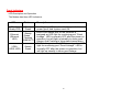
Front Indicators
LED Description and Operation
The Modem has three LED indicators.
LEDs
Status
Ready
(Ready LED)
Steady
Green
Ethernet
(Ethernet
LED)
Steady
Green
Flashing
(LINK/ACT)
VDSL
(VDSL LED)
Steady
Green
Descriptions
It will light up (ON) to show that the product is
power good, and system reset OK.
Each RJ45 station port on the Ethernet is
assigned an LED light for monitoring port “Good
Linkage”. LED is normally OFF after the power on
operation, but will light up steadily to show good
linkage. And Flashing to show data transmission.
RJ11 station port on the VDSL is assigned an LED
light for monitoring port “Good Linkage”. LED is
normally OFF after the power on operation, but
will light up steadily to show good linkage.
10
Rear Panel
The following figure shows the rear connectors
Figure Chapter 2.3 Rear Connectors
Modem Rear Side Connectors
Connectors
Line
Phone
LWD
Ethernet
Description
For connecting to the RJ-11 wall jack Using a RJ-11 cable
For connecting to the telephone or Fax or ISDN modem
For recovering LINK status between CPE & CO
For connecting to a Ethernet equipped device
Power On
1. Check the Modem is properly connected
2. Verify the power LED is steadily on
11
Type
RJ-11
RJ-11
N/A
RJ-45
4.Applications
APPLICATION FOR HOME NETWORKING
The 10Mbps Modem is used to connect any device equipped with a standard 10/100Mbps Ethernet port to a VDSL LAN.
The Modem have been designed to operate on the telephone wire installed in homes throughout the world. They utilize the same
modular patch cords and connectors commonly used for telephones.
To install the Modem or to access the Internet, you simply plug into your existing telephone jacks just like you would a telephone
modem or a fax machine. There is no need for special splitters, terminators or filters. In fact, there is no need to add or modify the
home telephone wiring at all.
The Modem uses a frequency division multiplexing approach that enables standard telephone wiring to simultaneously carry POTS
voice, ISDN and VDSL signals without any of the services impacting each other.
12
Appendix A: Cable Requirement
A CAT 3,4 or 5 UTP (unshielded twisted pair) cable is typically used to connect the Ethernet device to the Modem.
A 10Base-T cable often consists of four pairs of wires, two of which are used for transmission. The connector at the end of the 10Base-T
cable is referred to as an RJ-45 connector and it consists of eight pins.
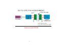
The Ethernet standard uses pins 1,2,3 and 6 for data transmission purposes.
Table RJ-45 Ethernet Connector Pin out Assignments
MNEMONIC
FUNCTION
PIN
TX+
Ethernet differential Transmit signal(+)
1
2
TXEthernet differential Transmit signal(-)
3
RX+
Ethernet differential receive signal(+)
4
NC
Unused
5
NC
Unused
6
RXEthernet differential receive signal(-)
7
NC
Unused
8
NC
Unused
13
Standard telephone wire of any gauge or type-flat, twisted or quad is used to connect the Modem to the telephone network. A telephone
cable typically consists of three pairs of wires, one of which is used for transmission. The connector at the end of the telephone cable is
called an RJ-11 connector and it consists of six pins. POTS (plain old telephone services) use pins 3 and 4 for voice transmission. A
telephone cable is shown below.
Figure
Telephone cable
A
B
The A and B connectors on the rear of the Modem are RJ-11 connectors. These connectors are wired identically. The RJ-11 connectors
have six positions, two of which are wiring, The Modem uses the center two pins. The pin out assignment for these connectors is
presented below.
Table
Pin#
1
2
3
4
5
6
RJ-11 Pin
MNEMONIC
NC
NC
TIP
RING
NC
NC
out Assignments
FUNCTION
Unused
Unused
POTS
POTS
Unused
Unused_
14
Appendix B: Product Specification
Product NameVDSL To Ethernet Modem (VDSL Modem)
ApplicationHome networking solution
Product Specification
Compliant with IEEE 802.3 & 802.3u Ethernet Standards
Compliant with ETSI, ITU, ANSI VDSL standards.
Provides 1 x 10/100M auto-sensing RJ-45 Ethernet ports.
Provides 1 x VDSL RJ-11 port.
Provides 1 x POTS / ISDN RJ-11 splitter on board.
Spectral compatibility with xDSL, ISDN (2B1Q/4B3T).
Robust operation on severely distorted line.
Symmetric and asymmetric data transmission on the same line.
Supports flow control IEEE802.3x for Full Duplex & Back Pressure for Half Duplex.
Long driver capable up to 1.9Km(4/1Mbps)1.5Km(5Mbps) /1.2Km(10M)/1Km(15M).
Surge protection.
Provides Ready LED.
Provides LED indication Link/Active Status for Ethernet port and Link for VDSL port.
External switching power adapter Input: AC 100-240 volts/50-60Hz;
Output: DC 5V/1A or above.
Dimensions: 95 x 110 x 24 mm.
Operating Temperature : 0°C~50°C(32F ~ 122F).
Humidity: 10%~90% non-condensing.
EMI by FCC/CE
Safety by EN60950
15
Power Consumption: 2.5W
Chipset : Infineon 10Base-S
16
Appendix C: Troubleshooting
Diagnosing the Modem’s Indicators
The Modem can be easily monitored through its comprehensive panel indicators. These indicators assist the network manager in
identifying problems the hub may encounter. This section describes common problems you may encounter and possible solutions
1. Symptom: Ready indicator does not light up (green) after power on.
Cause: Symptom External power supply
Solution: Check the power plug by plugging in another that is functioning properly. Check the power cord with another device. If
these measures fail to resolve the problem, have the unit power supply replaced by a qualified distributor.
2 .Symptom: Link indicator does not light up (green) after making a connection.
Cause: Network interface (e.g, a network adapter card on the attached device), network cable, or switch port is defective.
Solution:
2.1 Power off them Power on the VDSL Modem.
2.2 Verify that the switch and attached device are powered on.
2.3 Be sure the cable is plugged into both the switch and corresponding device.
2.4 Verify that the proper cable type is used and its length does not exceed specified limits.
2.5 Check the Modem on the attached device and cable connections for possible defects.
2.6 Replace the defective Modem or cable if necessary.
17
2.7 Verify the VDSL switch and VDSL Modem during the same speed mode. You can select VDSL Speed mode by 10 Mbps.
2.8 speed mode can link and work. VDSL default translation mode is 10 Mbps.
3. Symptom: VDSL Link can not be established.
Cause: Rusted phone wire, not standard 24 gauge phone wire, not twisted-pair phone wire, Wrong speed mode.
Solution: Check if speed of CO and CPE is in the same speed mode else please increase interleaver depth value to 8 or above.
4.Symptom: We tested with a regular S0 bus from an NTBA - data works, but ISDN telephone does not.
Solution:You have to connect as following chart if you want to connect CO and CPE Modem with NTBA.
18
Disable and enable CPE LWD
19
System Diagnostics
Power and Cooling Problems
If the POWER indicator does not turn on when the power cord is plugged in, you may have a problem with the power outlet, power
cord, or internal power supply as explained in the previous section. However, if the unit power is off after running for a while, check
for loose power connections, power losses or surges at the power outlet, and verify that the fan on back of the unit is unobstructed
and running prior to shutdown. If you still cannot isolate the problem, then the internal power supply may be defective. In this case,
contact your dealer.
Installation
Verify that all system components have been properly installed. If one or more components appear to be malfunctioning (e.g., the
power cord or network cabling), test them in an alternate environment where you are sure that all the other components are
functioning properly.
Transmission Mode
The default method of selecting the transmission mode for RJ-45 ports is 10/100 Mbps ETHERNET, for RJ-11 port are 10Mbps
VDSL. Therefore, if the Link signal is disrupted (e.g., by unplugging the network cable and plugging it back in again, or by resetting
the power), the port will try to reestablish communications with the attached device via auto-negotiation. If auto-negotiation fails, then
communications are set to half duplex by default. Based on this type of industry-standard connection policy, if you are using a
full-duplex device that does not support auto-negotiation, communications can be easily lost (i.e., reset to the wrong mode)
whenever the attached device is reset or experiences a power fluctuation. The best way to resolve this problem is to upgrade these
devices to a version that support Ethernet and VDSL.
20
Physical Configuration
If problems occur after altering the network configuration, restore the original connections, and try to track the problem down by
implementing the new changes, one step at a time. Ensure that cable distances and other physical aspects of the installation do not
exceed recommendations.
System Integrity
As a last resort verify the switch integrity with a power-on reset. Turn the power to the switch off and then on several times. If the
problem still persists and you have completed all the preceding diagnoses, then contact your dealer.
21
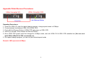
Appendix DLink Recover Procedures
Operating Procedures:
1. Power on VDSL CO, start the speed change program, change speed mode to 4/1Mbps.
2. Connect phone line between VDSL CO & VDSL CPE.
3. Push still Link Recover Button of VDSL CPE and power on VDSL CPE.
4. Wait for 5 seconds, then release Link Recover Button.
5. Now, VDSL CPE speed mode has changed to 4/1Mbps mode, wait until VDSL CO & VDSL CPE establish link {You can see that
both VDSL LEDs(CO & CPE) are steadily on}.
6. Run speed change program, you can set your desired speed mode.
Remark: LWD represents 4/1Mbps.
22
Appendix EAccessories-Bracket
Two Brackets
The brackets are specially designed to fix the VDSL Modem on the table to avoid someone to freely take it away, like in hotel rooms,
internet café or other public areas where providing the internet service. It is suggested to use with the wooden table. This is an optional
accessory, please contact with your local dealer for further service.
Note: Do not install plastic feet at the bottom of the VDSL CPE Modem when using brackets.
23
Appendix FCompliance and Safety Information
FCC Radio Frequency Interference Statement
This equipment has been tested and found to comply with the limits for a computing device, pursuant to Part 15 of FCC rules. These
limits are designed to provide reasonable protection against harmful interference when the equipment is operated in a commercial
environment. This equipment generates, uses and can radiate radio frequency energy and, if not installed and used in accordance with
the instructions, may cause harmful interference to radio communications. However, there is no guarantee that interference will not occur
in a particular installation. If this equipment does cause harmful interference to radio or television reception, which can be determined by
turning the equipment off and on, the user is encouraged to try to correct the interference by one or more of the following measures
1. Reorient or relocate the receiving antenna.
2. Increase the separation between the equipment and receiver.
3. The equipment and the receiver should be connected to outlets on separate circuits.
4. Consult the dealer or an experienced radio/television technician for help.
Changes or modifications not expressly approved by the party responsible for compliance could void the user’s authority to operate the
equipment.
If this telephone equipment causes harm to the telephone network, the telephone company will notify you in advance that temporary
discontinuance of service may be required. But if advance notice isn’t practical, the telephone company will notify the customer as soon
as possible. Also, you will be advised of your right to file a complaint with the FCC if you believe it is necessary. The telephone company
may make changes in its facilities, equipment, operations or procedures that could affect the proper functioning of your equipment. If
they do, you will be notified in advance in order for you to make necessary modifications to maintain uninterrupted service. This
equipment may not be used on coin service provided by the telephone company. Connection to party lines is subject to state tariffs
24
Important Safety Instructions
CautionThe direct plug-in wall transformer serves as the main disconnect for the product. The socket outlet shall be installed near the
product and be readily accessible.
CautionUse only the power supply included with this product. In the event the power supply is lost or damagedIn the United States,
use only with CSA certified or UL listed Class 2 power supply, rated 5Vdc 1A or above.
IN Europe, use only with CE certified power supply, rated 5Vdc 1A or above.
Do not use this equipment near water, for example in a wet basement.
Avoid using a telephone during an electrical storm. There may be a remote risk of electrical shock from lightning.
Do not use the telephone to report a gas leak in the vicinity of the leak.
If trouble is experienced with this unit, please contact customer service at the address and phone listed below. Do not disassemble this
equipment. It does not contain any user serviceable components.
25
FCC Warning
This equipment has been tested and found to comply with the limits for a Class A digital device, pursuant to Part 15 of the FCC Rules.
These limits are designed to provide reasonable protection against harmful interference when the equipment is operated in a commercial
environment. This equipment generates, uses, and can radiate radio frequency energy and, if not installed and used in accordance with
the instruction manual, may cause harmful interference to radio communications. Operation of this equipment in a residential area is
likely to cause harmful interference in which case the user will be required to correct the interference at his own expense.
CE Mark Warning
This is a CE class A product. In a domestic environment, this product may cause radio interference in which case the user may be
required to take adequate measures.
26
Warranty
The original owner that the product delivered in this package will be free from defects in material and workmanship for one year parts
after purchase. For the warranty to apply, you must register your purchase by returning the registration card indicating the date of
purchase.
There will be a minimal charge to replace consumable components, such as fuses, power transformers, and mechanical cooling devices.
The warranty will not apply to any products which have been subjected to any misuse, neglect or accidental damage, or which contain
defects which are in any way attributable to improper installation or to alteration or repairs made or performed by any person not under
control of the original owner.
The above warranty is in lieu of any other warranty, whether express, implied, or statutory, including but not limited to any warranty of
merchantability, fitness for a particular purpose, or any warranty arising out of any proposal, specification, or sample. Shall not be liable
for incidental or consequential damages. We neither assumes nor authorizes any person to assume for it any other liability.
Note: Please do not tear off or remove the warranty sticker as shown, otherwise the warranty will be voi d.
27